Embed Size (px)
Citation preview
Making video presentations from the Evans and Sutherland PS390
D. E. Jackson, A. M. Waite and P. M. Williams
Department of Pharmaceutical Sciences, University of Nottingham, Nottingham, UK
The presentation of S-dimensional and dynamic molecular information is often impaired by the use of conventional static display media. This paper explains a simple procedure for the direct capture onto video of graphical output from the Evans and Sutherland PS390 display. A technique for the integration of molecular images with supplementary tex- tual and graphical information provided by commercial video titling software is also explained. We have found such pre- sentation techniques to be of particular value in both the presentation of research results and in the preparation of material for use in a teaching environment.
tional television format. The standard PS390 display mon- itor is driven at 54 kHz line and 60 Hz frame noninterlaced. In order to comply with the PAL (SECAM) standard em- ployed by European television systems, these parameters must be altered to 15.625 kHz line and 25 Hz frame inter- laced. This format is one of three software-selectable output options available to the user.’ However, in order to com- pensate for the resulting reduction in resolution, overscan and aspect-ratio, the picture viewport must also be altered. Both output format and viewport are most conveniently changed by the use of a single command file on the host computer. Similarly the system can be reset to the original formats using a second instruction file (see Appendix 1).
Keywords: Evans and Sutherland (E&S), video presenta- tion, molecular modeling
INTRODUCTION
The developments in both computational chemistry and computer graphics over the past several years have given rise to a much greater understanding of the spatial and dynamic properties of molecules which govern their intra- and intermolecular behavior. As a consequence, there is an increasing need in both research and teaching environments for a clear medium in which to convey this information. Conventional static display tools such as 35mm transpar- encies and overhead projection media are insufficient to accurately convey dynamic and 3-dimensional information. Herein we describe a relatively inexpensive method for the production of video presentation material that is ideally suited to these needs.
The output from the PS390 control box to the display consists of an RGB signal (i.e., three separate video sig- nals-red, green and blue) with composite synch carried on the green video signal. The RGB format is inappropriate for use with domestic video recorders which, in general, require a composite video input. Composite information comprises color, intensity and synchronization all within one signal, and the merging of three separate RGB signals to give a composite video signal is achieved by the use of an encoder. The choice of encoder can significantly affect the quality of the final video and for the purposes described here the Electrocraft PE-763 video encoder has proven to be most suitable. However, in order to allow the output signal to be switched easily from the PS390 display to the television screen, and vice versa, a modification to the en- coder as described below is desirable.
MODIFICATIONS TO THE VIDEO ENCODER PE-763
THE EVANS AND SUTHERLAND DISPLAY SYSTEM
The PS390 is the first E&S Picture System to employ raster technology for its interactive graphical display and, as such, is the first of their machines to be compatible with conven-
Address reprint requests to Dr. Jackson at the Department of Pharmaceu- tical Sciences, University of Nottingham, Nottingham NG7 2RD, UK. Received 24 August 1989; accepted 19 September 1989
A simple T-junction on the RGB inputs from the PS390 controller to the display allows the PAL encoder to be con- nected into the system as originally suggested by E&S. However, this method has been found to result in a reduction in picture clarity on the PS390 monitor which becomes quite apparent and undesirable when the encoder is switched on. Also, when the commands altering the picture viewport are issued to view the picture on the TV screen via the encoder, an unintelligible picture is displayed concurrently on the
0 1990 Butterworth Publishers J. Mol. Graphics, 1990, Vol. 8, March 31
PS390 monitor. A slight modification to the encoder, as described in Appendix 2, to include a switch for the output signal to direct it to either the PS390 or to the television screen, overcomes this difficulty. This configuration then allows the encoder to be powered up continuously, irre- spective of the signal destination, with the newly-fitted switch being used, in conjunction with the host resident instruction file, to route the signal to one monitor or the other.
VIDEO TITLING
In order to enhance the graphical information captured from the molecular modeling system it is often useful to add supplementary textual and graphical images. Software pack- ages specifically designed for this task and which are readily available for the Commodore Amiga personal computer al- low the user to choose not only a variety of legend types but also offer a selection of wiping and fading styles between title frames. This latter facility in particular is extremely useful for generating continuity in the presentation. Pro- grams which we have found to be particularly useful include the Aegis Video Titler,2 Electronic Arts DeluxePaint II3 and Byte by Byte Sculpt-Animate 3D.4
The video presentation may be further enhanced by the integration of these supplementary textual and graphical images with the molecular images generated by the PS390. In order to achieve the overlaying of the Amiga display on to the signal from the PS390, a Genlock is used.
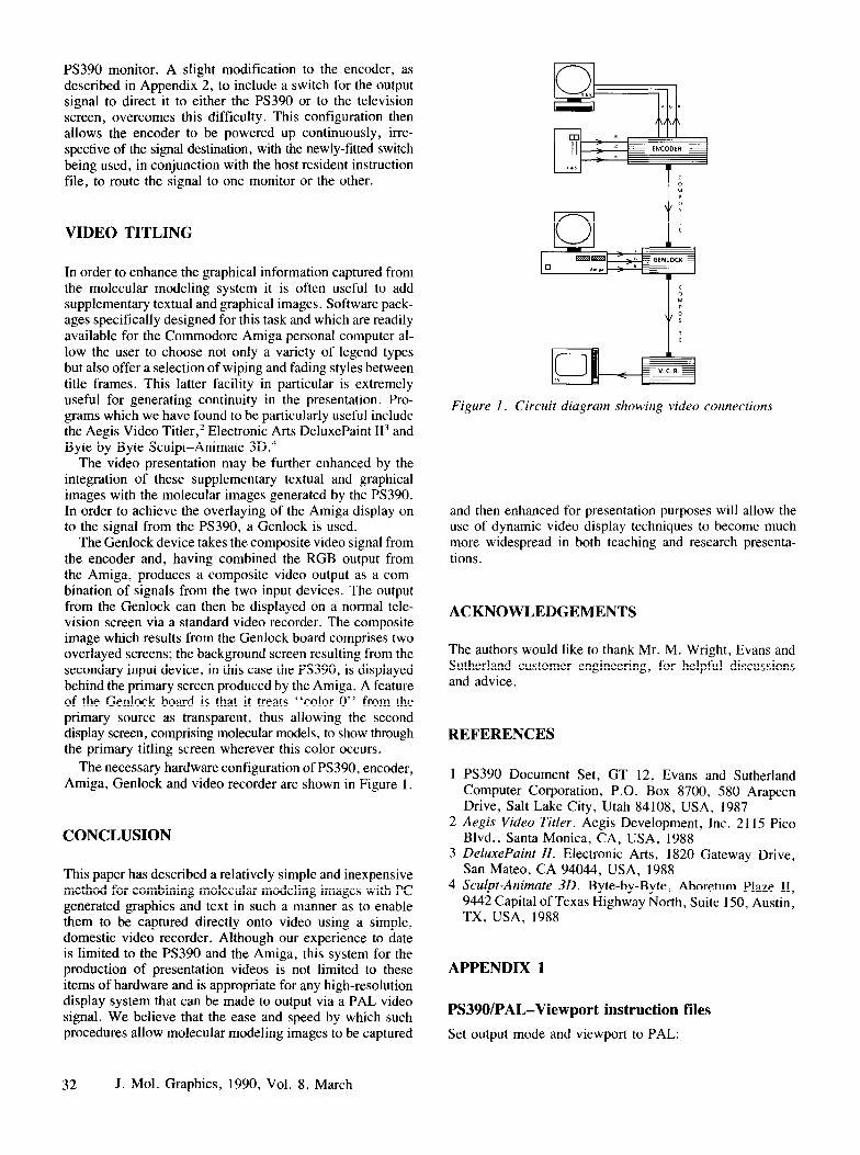
The Genlock device takes the composite video signal from the encoder and, having combined the RGB output from the Amiga, produces a composite video output as a com- bination of signals from the two input devices. The output from the Genlock can then be displayed on a normal tele- vision screen via a standard video recorder. The composite image which results from the Genlock board comprises two overlayed screens; the background screen resulting from the secondary input device, in this case the PS390, is displayed behind the primary screen produced by the Amiga. A feature of the Genlock board is that it treats “color 0” from the primary source as transparent, thus allowing the second display screen, comprising molecular models, to show through the primary titling screen wherever this color occurs.
The necessary hardware configuration of PS390, encoder, Amiga, Genlock and video recorder are shown in Figure 1.
CONCLUSION
This paper has described a relatively simple and inexpensive method for combining molecular modeling images with PC generated graphics and text in such a manner as to enable them to be captured directly onto video using a simple, domestic video recorder. Although our experience to date is limited to the PS390 and the Amiga, this system for the production of presentation videos is not limited to these items of hardware and is appropriate for any high-resolution display system that can be made to output via a PAL video signal. We believe that the ease and speed by which such procedures allow molecular modeling images to be captured
32 J. Mol. Graphics, 1990, Vol. 8, March
Figure I. Circuit diagram showing video connections
and then enhanced for presentation purposes will allow the use of dynamic video display techniques to become much more widespread in both teaching and research presenta- tions .
ACKNOWLEDGEMENTS
The authors would like to thank Mr. M. Wright, Evans and Sutherland customer engineering, for helpful discussions and advice.
REFERENCES
PS390 Document Set, GT 12, Evans and Sutherland Computer Corporation, P.O. Box 8700, 580 Arapeen Drive, Salt Lake City, Utah 84108, USA, 1987 Aegis Video Titler. Aegis Development, Inc. 2 115 Pica Blvd., Santa Monica, CA, USA, 1988 DeluxePaint II. Electronic Arts, 1820 Gateway Drive, San Mateo, CA 94044, USA, 1988 Sculpt-Animate 30. Byte-by-Byte, Aboretum Plaze II, 9442 Capital of Texas Highway North, Suite 150, Austin, TX, USA, 1988
APPENDIX 1
PS390/PAL-Viewport instruction files
Set output mode and viewport to PAL:
configure a; voff$: = view hor = -.75:.25 vert = -0.06:.93 inten = 0:.7 then xxxl$;
xKxl$: = select filter 2 then hvpl$; finish configuration; send v3d(50, 225, 700) to (3)shadingenvironment; send v3d(50, 225, 700) to (4)m2cpktripcolor; send fix(3) to (5)ps390env; send true to (l)ps390env;
Return output mode and viewport to default settings:
configure a; vpfl$: = view hor = -.825:.825 vert = -0.65:1 inten finish configuration; send fix(O) to (5)ps390env; send true to (l)ps390env;
APPENDIX 2
Modifications to the Electrocraft PE-763 encoder:
Requirements:
3x
6x IX
IX
4m IX
BNC 75R bulkhead sockets. BNC 750 plugs. 6v, 4-pole changeover relay. SPST switch, simple on/off. 75fi video cable. circuit “breadboard’ ’ .
nylon spacers, nuts & bolts to fit and mount.
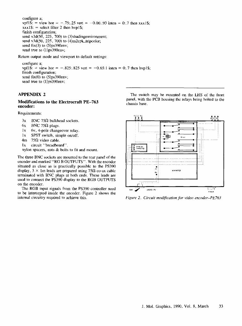
The three BNC sockets are mounted to the rear panel of the encoder and marked “RG B OUTPUTS”. With the encoder situated as close as is practically possible to the PS390 display, 3 X lm leads are prepared using 75R co-ax cable terminated with BNC plugs at both ends. These leads are used to connect the PS390 display to the RGB OUTPUTS on the encoder.
The RGB input signals from the PS390 controller need to be intercepted inside the encoder. Figure 2 shows the internal circuitry required to achieve this.
= 0:.7 then hvpl$;
The switch may be mounted on the LHS of the front panel, with the PCB housing the relays being bolted to the chassis base.
: : : : : : : : : : : : .j. . . .
: : a.. ~ . ..,.: j
:
Figure 2. Circuit modification for video encoder-PE763
J. Mol. Graphics, 1990, Vol. 8, March 33