Embed Size (px)
Citation preview
High PerformanceSwitching and RoutingTelecom Center Workshop: Sept 4, 1997.
Making Parallel Packet Switches Practical
Sundar Iyer, Nick McKeown(sundaes,nickm)@stanford.eduDepartments of Electrical Engineering & Computer Science, Stanford Universityhttp://klamath.stanford.edu/pps
Stanford University 2
Motivation
To design and analyze:
– an architecture of a very high capacity packet switch
– in which the memories run slower than the line rate”
[Ref: S. Iyer, A. Awadallah, N. McKeown, “Analysis ofPacket Switch with Memories Running Slower than the LineRate, Proc. Infocom, Tel Aviv, Mar 2000.]

Stanford University 3
What limits capacity of packet switches today?
• Memory bandwidth for packet buffers– Shared memory: B = 2NR– Input queued: B = 2R
• Switch Arbitration– At the line rate R
• Packet Processing– At the line rate R
Stanford University 4
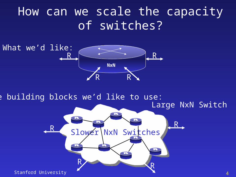
How can we scale the capacity of switches?
What we’d like:R
R R
RNxN
The building blocks we’d like to use:
R
RR
R Slower NxN Switches
Large NxN Switch
Stanford University 5
Why this might be a good idea
• Larger Capacity
• Slower than the line rate
– Buffering– Arbitration– Packet Processing
• Redundancy
Stanford University 6
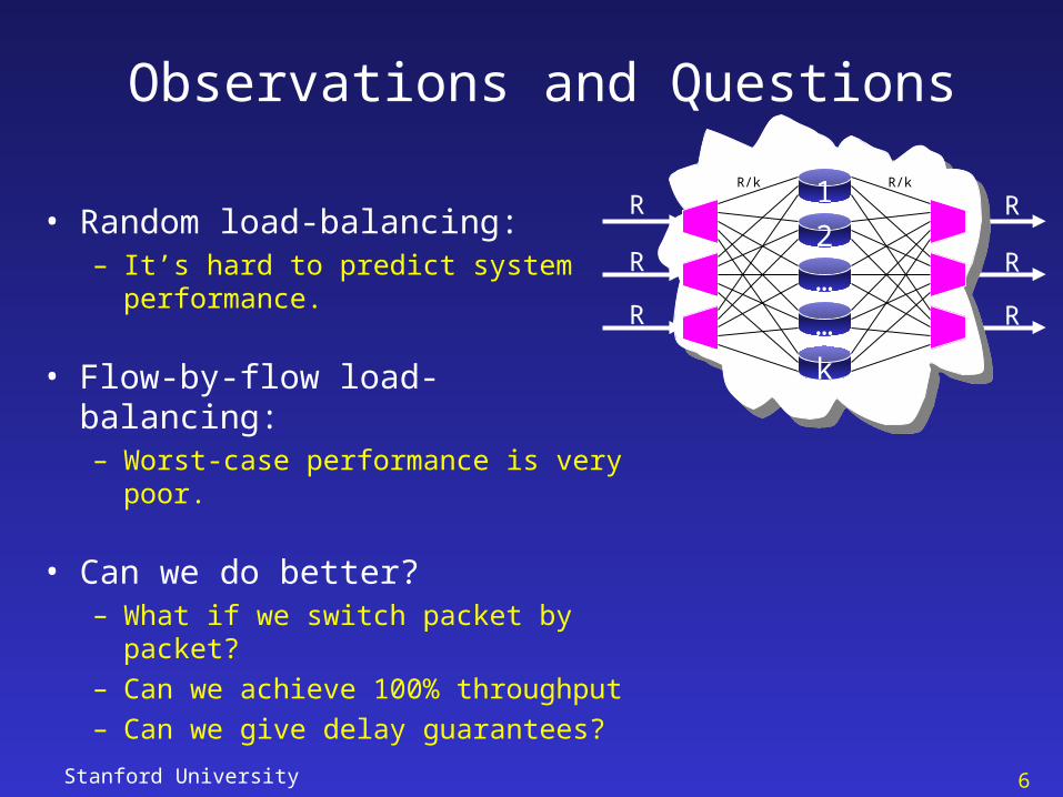
Observations and Questions
• Random load-balancing: – It’s hard to predict system
performance.
• Flow-by-flow load-balancing: – Worst-case performance is very
poor.
• Can we do better?– What if we switch packet by
packet?– Can we achieve 100% throughput– Can we give delay guarantees?
1
2
…
…
k
R
R
R
R/k R/k
R
R
R
Stanford University 7
Architecture of a PPS
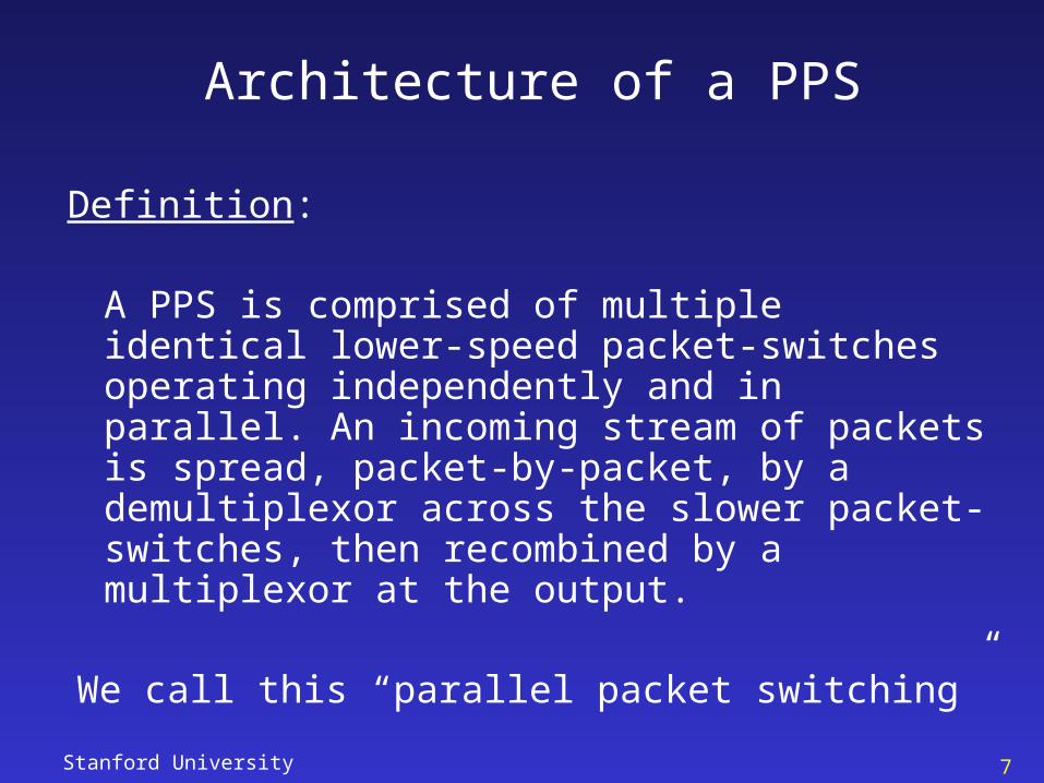
Definition:
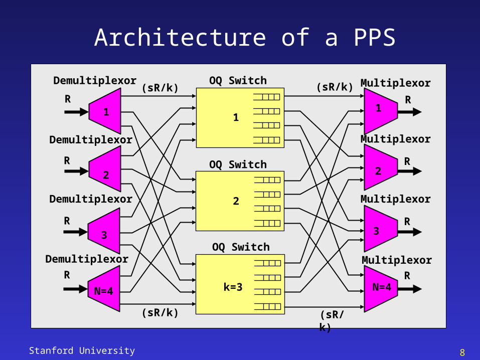
A PPS is comprised of multiple identical lower-speed packet-switches operating independently and in parallel. An incoming stream of packets is spread, packet-by-packet, by a demultiplexor across the slower packet-switches, then recombined by a multiplexor at the output.
We call this “parallel packet switching”
Stanford University 8
Architecture of a PPS
OQ Switch
OQ Switch
OQ Switch
1
2
3
N=4
R
R
R
R
1
2
3
N=4
R
R
R
R
MultiplexorDemultiplexor
Demultiplexor
Demultiplexor
Demultiplexor
Multiplexor
Multiplexor
Multiplexor
(sR/k) (sR/k)
k=3
1
2
(sR/k) (sR/k)
Stanford University 9
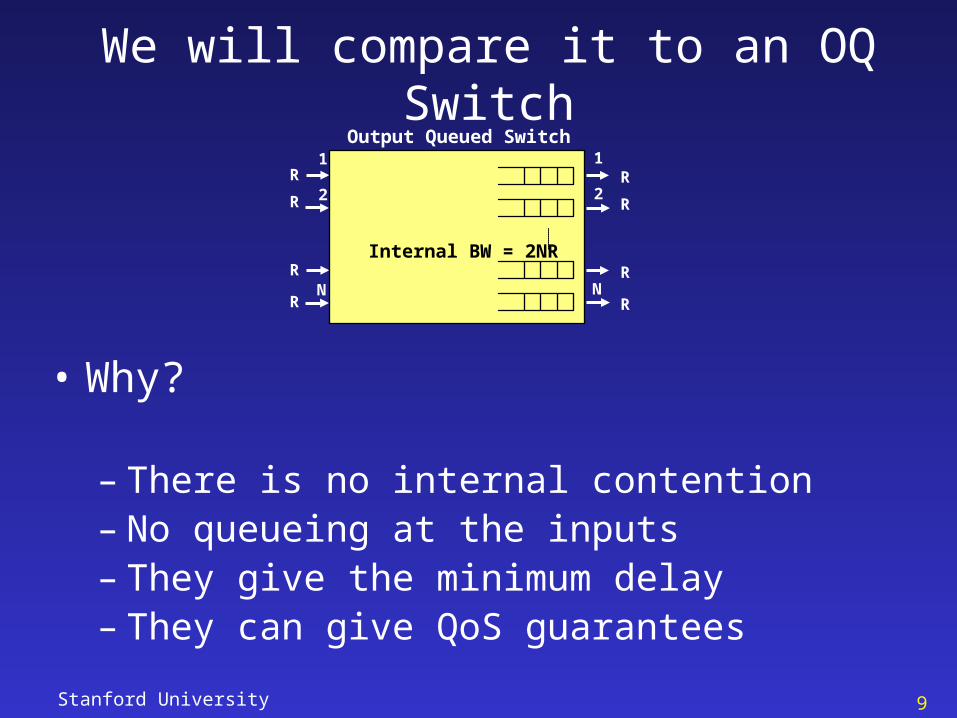
We will compare it to an OQ Switch
1
2
N
1
2
N
Output Queued Switch
R
R
R
R
R
R
R
R
Internal BW = 2NR
• Why?
– There is no internal contention – No queueing at the inputs– They give the minimum delay– They can give QoS guarantees
Stanford University 10
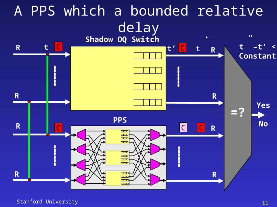
Definition
• Relative Queueing Delay
– This is defined as the increased queueing delay faced by a cell in the PPS relative to the delay it receives in a shadow output queued switch
– It includes the time difference attributed only due to queueing
– A switch is said to emulate an OQ switch if the relative queueing delay is zero
Stanford University 11
A PPS which a bounded relative delayShadow OQ Switch
R
R
R
R
R
R
R
R
PPS
Yes
No=?
C
C
t
C
Ct’
C C
t”Ct’ t” –t’ <Constant
Stanford University 12
Problem Statement Redefined
Motivation:
“To design and analyze an architecture of a very high capacity packet switch in which the memories run slower than the line rate, which preserves the good properties of an OQ switch”
This talk:
Expanding the capacity of a FIFO packet switch, with a bounded relative queueing delay, using the PPS architecture.
Stanford University 13
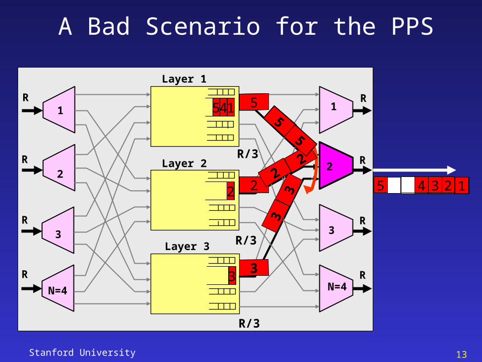
Layer 1
Layer 2
Layer 3
1
2
3
N=4
R
R
R
R
1
2
3
N=4
R
R
R
R
2
2
415
3
1
2
1
3
2
1
4
2
3
1
4
2 13
4
1234
5
123
5
1234 1234
5
12345
R/3
R/3
R/3
A Bad Scenario for the PPS
Stanford University 14
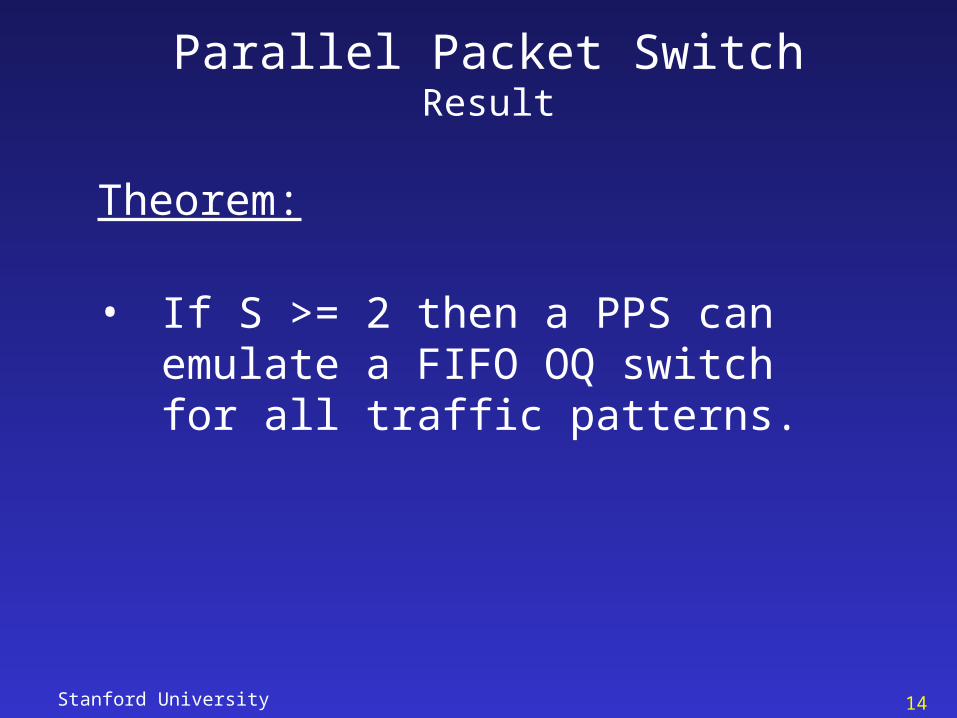
Parallel Packet SwitchResult
Theorem:
• If S >= 2 then a PPS can emulate a FIFO OQ switch for all traffic patterns.
Stanford University 15
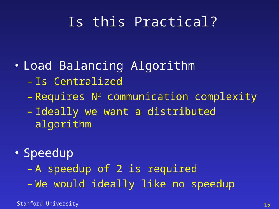
Is this Practical?
• Load Balancing Algorithm – Is Centralized– Requires N2 communication complexity– Ideally we want a distributed algorithm
• Speedup– A speedup of 2 is required– We would ideally like no speedup
Stanford University 16
Layer 1
Layer 2
Layer 3
1
2
3
N=4
R
R
R
R
1
2
3
N=4
R
R
R
R
2R/3
R/3
R/3
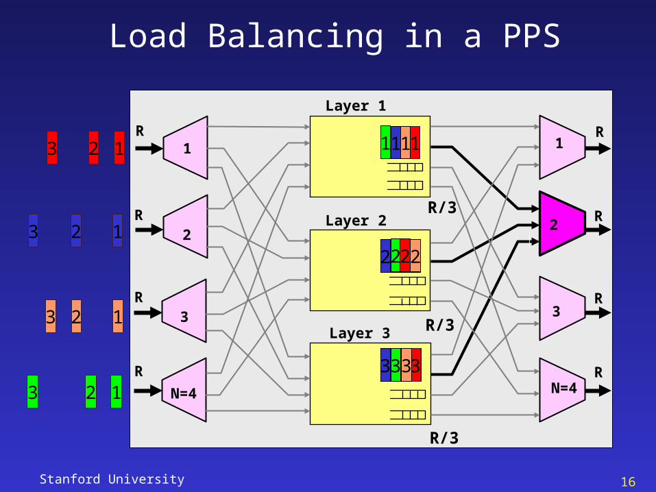
Load Balancing in a PPS
1
3
11 1
2
3
2
3
2 2
3
123
123
123
123
Stanford University 17
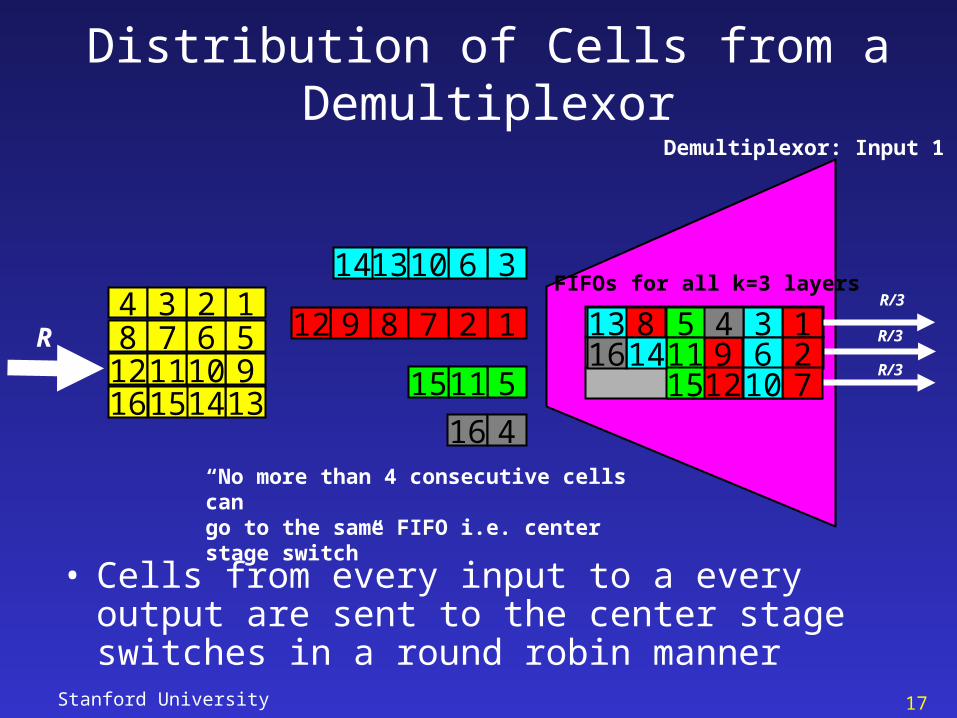
Distribution of Cells from a Demultiplexor
R124 3568 791012 11
131416 1551115
16 4
128912 7 R/3
R/3
R/3
Demultiplexor: Input 1
FIFOs for all k=3 layers
912
127
8 51115
36
1014
13
3613 1014
416
• Cells from every input to a every output are sent to the center stage switches in a round robin manner
“No more than 4 consecutive cells can go to the same FIFO i.e. center stage switch”
Stanford University 18
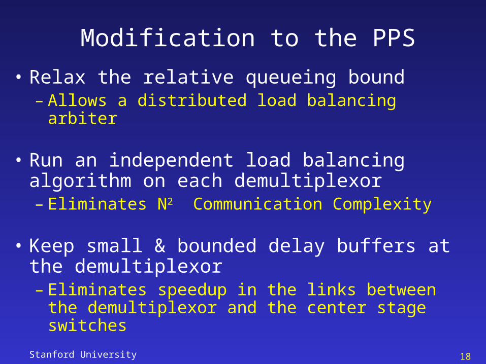
Modification to the PPS
• Relax the relative queueing bound– Allows a distributed load balancing arbiter
• Run an independent load balancing algorithm on each demultiplexor– Eliminates N2 Communication Complexity
• Keep small & bounded delay buffers at the demultiplexor– Eliminates speedup in the links between the
demultiplexor and the center stage switches
Stanford University 19
Layer 1
Layer 2
Layer 3
1
2
3
N=4
R
R
R
R
1
2
3
N=4
R
R
R
R
2
1
2
3 3
2
1R/3
R/3
R/3
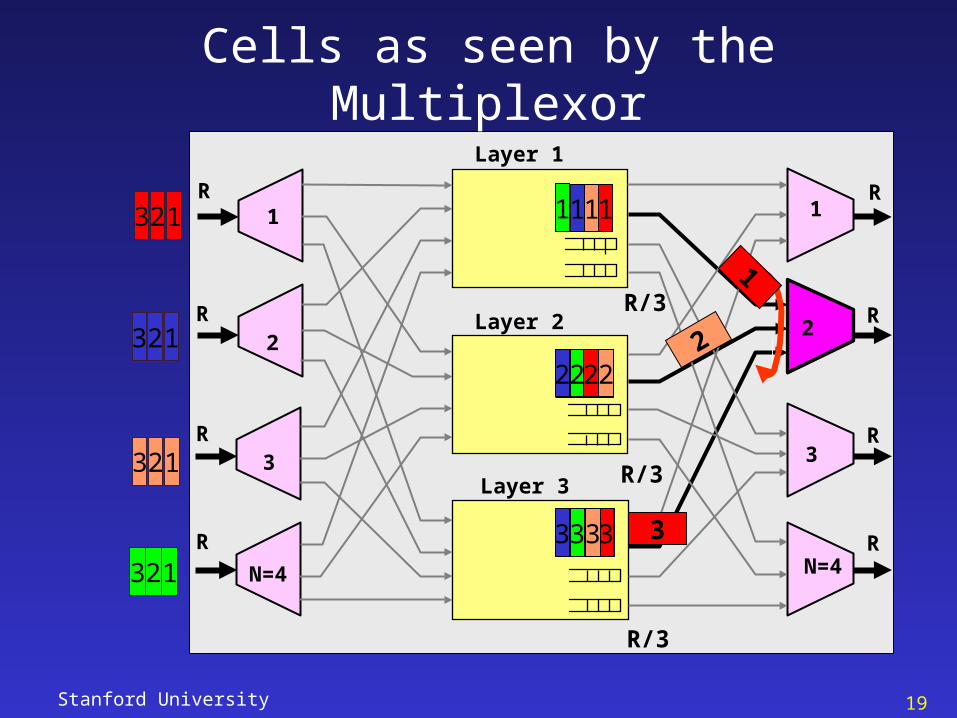
Cells as seen by the Multiplexor
1
3
2
1
3
2
1
2
3
123
123
123
123
Stanford University 20
Solution
• Read – cells from the corresponding queues (which may
be out of order) based on the arrival time from all center stage switches to maintain throughput
• Introduce – a small and bounded re-sequencing buffer at the
multiplexor to re-order cells and send them in sequence
• Tolerate – a bounded delay relative to the shadow FIFO OQ
switch
Stanford University 21
Properties of the PPS Demultiplexor
• Demultiplexors
– Cells arrive at combined rate R over all k FIFOs
– Each cell has a property: output
– Cells to same output are inserted into the k FIFOs in RR.
– Cells are written into each FIFO buffer at leaky bucket rate of less than R/Ck + N
– Cells are read from each FIFOs at constant service rate R/k
– Max delay faced by a cell is N internal time slots
Stanford University 22
Relative Queueing Delay faced by a Cell
• Demultiplexors– A maximum relative queueing delay of N
internal time slots is encountered by a cell
• Multiplexors– A maximum relative queueing delay of N
internal time slots is encountered by a cell
• Total Relative Queueing Delay– 2N time slots
Stanford University 23
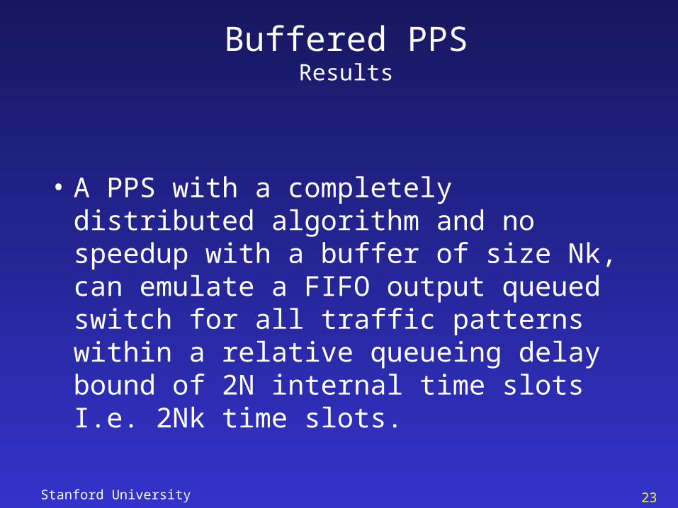
Buffered PPSResults
• A PPS with a completely distributed algorithm and no speedup with a buffer of size Nk, can emulate a FIFO output queued switch for all traffic patterns within a relative queueing delay bound of 2N internal time slots I.e. 2Nk time slots.
Stanford University 24
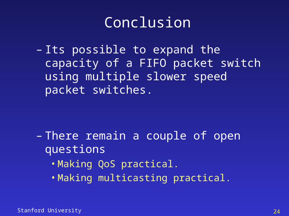
Conclusion
– Its possible to expand the capacity of a FIFO packet switch using multiple slower speed packet switches.
– There remain a couple of open questions• Making QoS practical.• Making multicasting practical.


![Ethane: Taking Control of the Enterprise - McKeown Groupklamath.stanford.edu/~nickm/papers/ethane-sigcomm07.pdf · security [24]. A Yankee Group report found that 62% of network Permission](https://img.pdfslide.us/doc/110x75/60c390eac4adf833487debec/ethane-taking-control-of-the-enterprise-mckeown-nickmpapersethane-sigcomm07pdf.jpg)