Embed Size (px)
Citation preview
Making a Custom Insert Cable
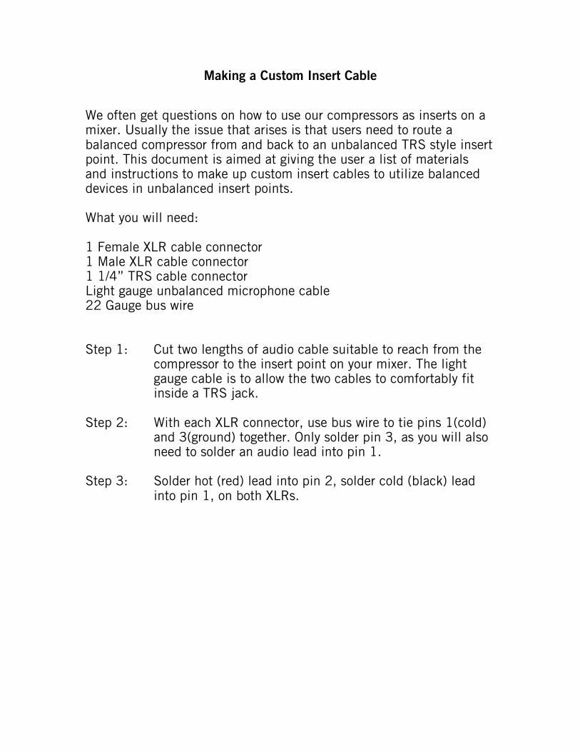
We often get questions on how to use our compressors as inserts on amixer. Usually the issue that arises is that users need to route abalanced compressor from and back to an unbalanced TRS style insertpoint. This document is aimed at giving the user a list of materialsand instructions to make up custom insert cables to utilize balanceddevices in unbalanced insert points.
What you will need:
1 Female XLR cable connector1 Male XLR cable connector1 1/4” TRS cable connectorLight gauge unbalanced microphone cable22 Gauge bus wire
Step 1: Cut two lengths of audio cable suitable to reach from thecompressor to the insert point on your mixer. The lightgauge cable is to allow the two cables to comfortably fitinside a TRS jack.
Step 2: With each XLR connector, use bus wire to tie pins 1(cold)and 3(ground) together. Only solder pin 3, as you will alsoneed to solder an audio lead into pin 1.
Step 3: Solder hot (red) lead into pin 2, solder cold (black) leadinto pin 1, on both XLRs.
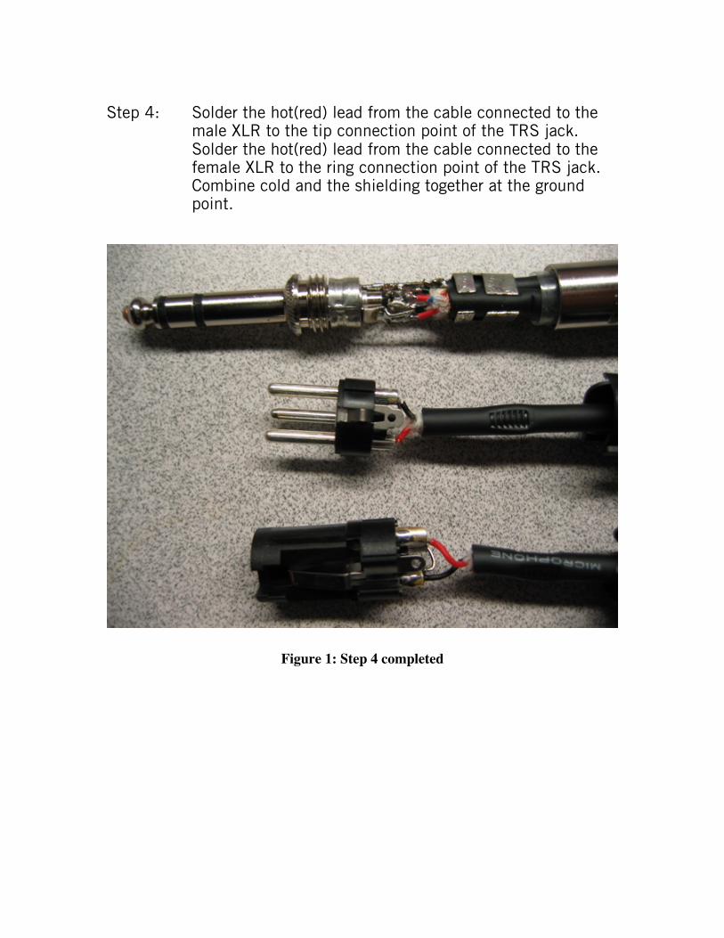
Step 4: Solder the hot(red) lead from the cable connected to themale XLR to the tip connection point of the TRS jack.Solder the hot(red) lead from the cable connected to thefemale XLR to the ring connection point of the TRS jack.Combine cold and the shielding together at the groundpoint.
Figure 1: Step 4 completed
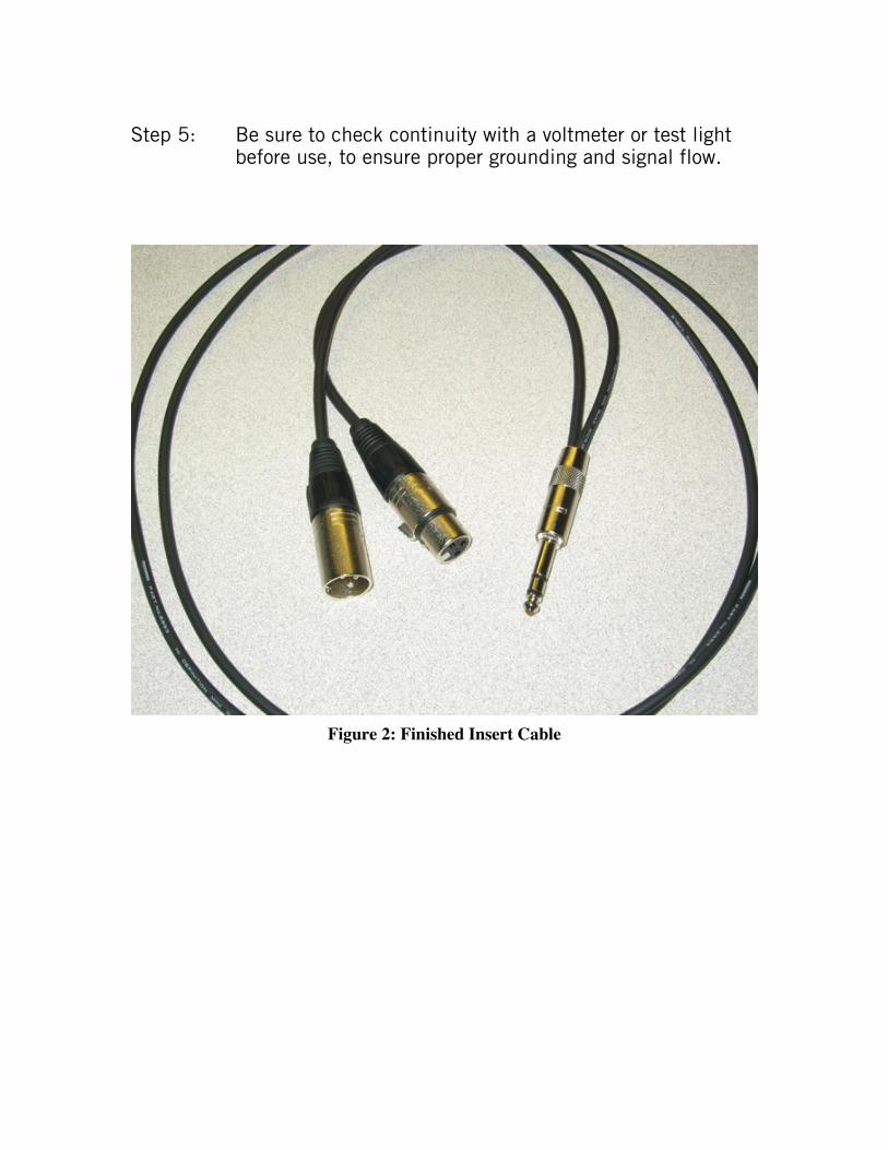
Step 5: Be sure to check continuity with a voltmeter or test lightbefore use, to ensure proper grounding and signal flow.
Figure 2: Finished Insert Cable


![Insert Date [Date menu under insert] Kirsch Custom Ambiance Shades](https://img.pdfslide.us/doc/110x75/5697bf9c1a28abf838c9378d/insert-date-date-menu-under-insert-kirsch-custom-ambiance-shades.jpg)

![[INSERT SPEAKER’S NAME] [INSERT TITLE] [INSERT DATE]](https://img.pdfslide.us/doc/110x75/56812c68550346895d90fff9/insert-speakers-name-insert-title-insert-date-5685c9ae3d2da.jpg)
![Facilitator: [Insert name] Date: [Insert] Venue: [Insert] Wellcome !](https://img.pdfslide.us/doc/110x75/56649dd05503460f94ac59be/facilitator-insert-name-date-insert-venue-insert-wellcome-.jpg)