Embed Size (px)
Citation preview
UVic Mechanical Engineering 2017-01-03 (Rev. 1) MakerCase SVG to DXF Conversion Guide
1
Makercase SVG to DXF Conversion This procedure describes how to create a DXF version of the box plans generated on the MakerCase
website and make modifications to it in SolidWorks.
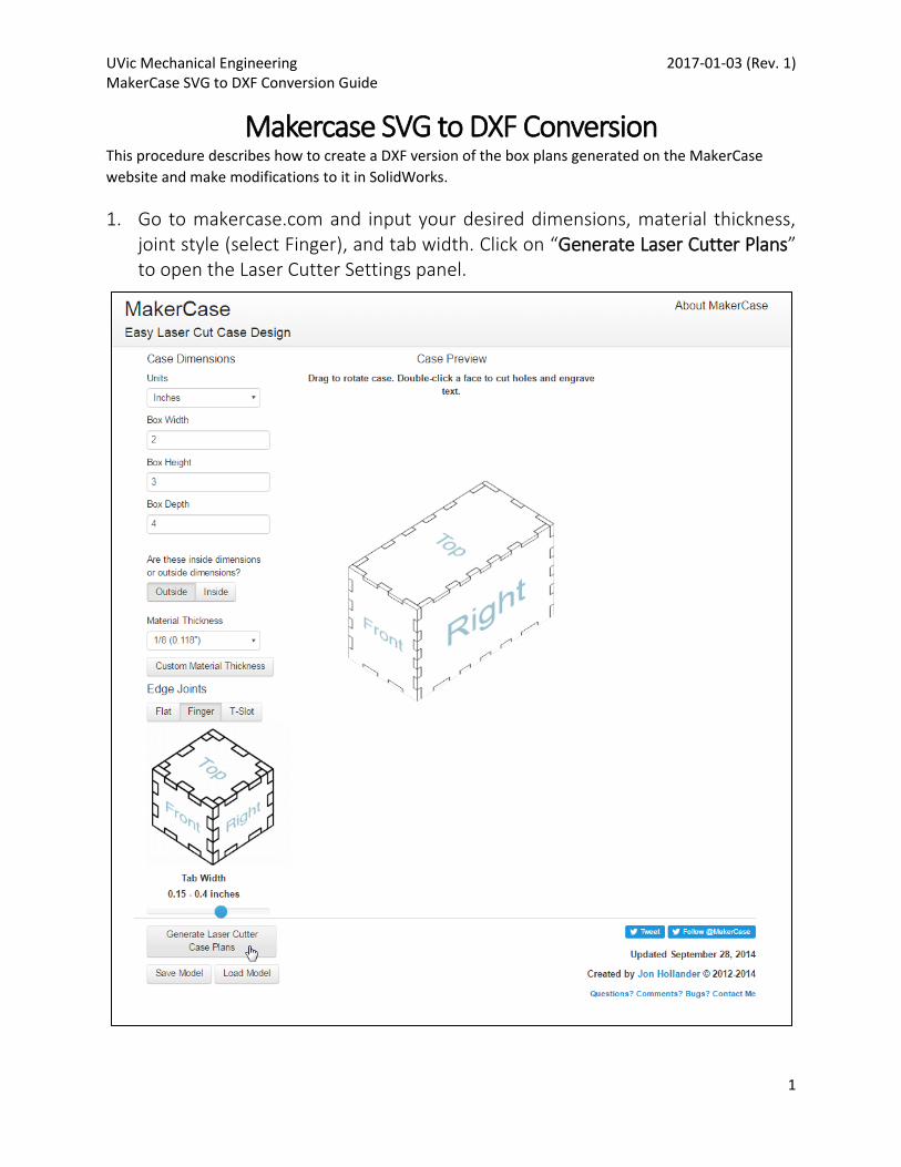
1. Go to makercase.com and input your desired dimensions, material thickness, joint style (select Finger), and tab width. Click on “Generate Laser Cutter Plans” to open the Laser Cutter Settings panel.
UVic Mechanical Engineering 2017-01-03 (Rev. 1) MakerCase SVG to DXF Conversion Guide
2
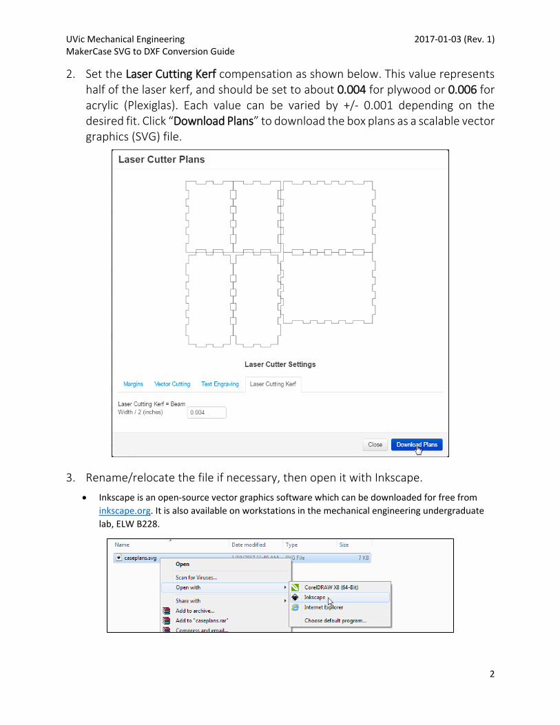
2. Set the Laser Cutting Kerf compensation as shown below. This value represents half of the laser kerf, and should be set to about 0.004 for plywood or 0.006 for acrylic (Plexiglas). Each value can be varied by +/- 0.001 depending on the desired fit. Click “Download Plans” to download the box plans as a scalable vector graphics (SVG) file.
3. Rename/relocate the file if necessary, then open it with Inkscape.
Inkscape is an open-source vector graphics software which can be downloaded for free from
inkscape.org. It is also available on workstations in the mechanical engineering undergraduate
lab, ELW B228.
UVic Mechanical Engineering 2017-01-03 (Rev. 1) MakerCase SVG to DXF Conversion Guide
3
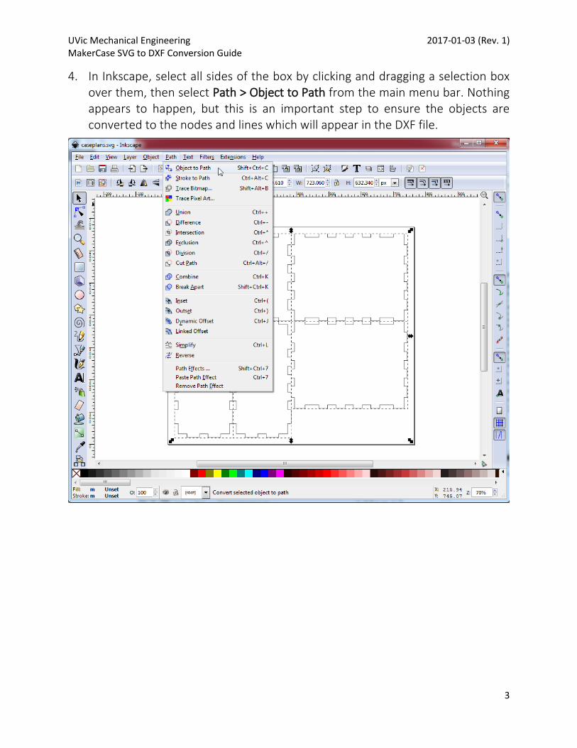
4. In Inkscape, select all sides of the box by clicking and dragging a selection box over them, then select Path > Object to Path from the main menu bar. Nothing appears to happen, but this is an important step to ensure the objects are converted to the nodes and lines which will appear in the DXF file.
UVic Mechanical Engineering 2017-01-03 (Rev. 1) MakerCase SVG to DXF Conversion Guide
4
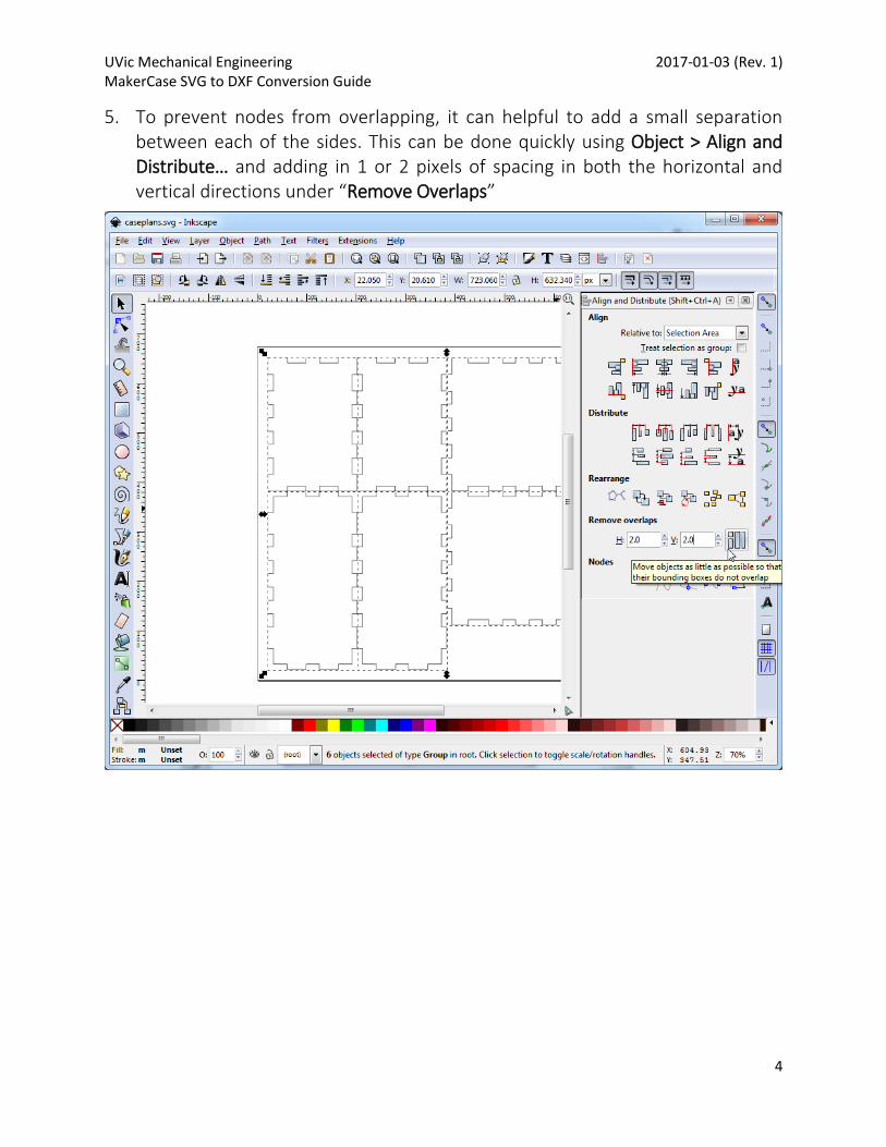
5. To prevent nodes from overlapping, it can helpful to add a small separation between each of the sides. This can be done quickly using Object > Align and Distribute… and adding in 1 or 2 pixels of spacing in both the horizontal and vertical directions under “Remove Overlaps”
UVic Mechanical Engineering 2017-01-03 (Rev. 1) MakerCase SVG to DXF Conversion Guide
5
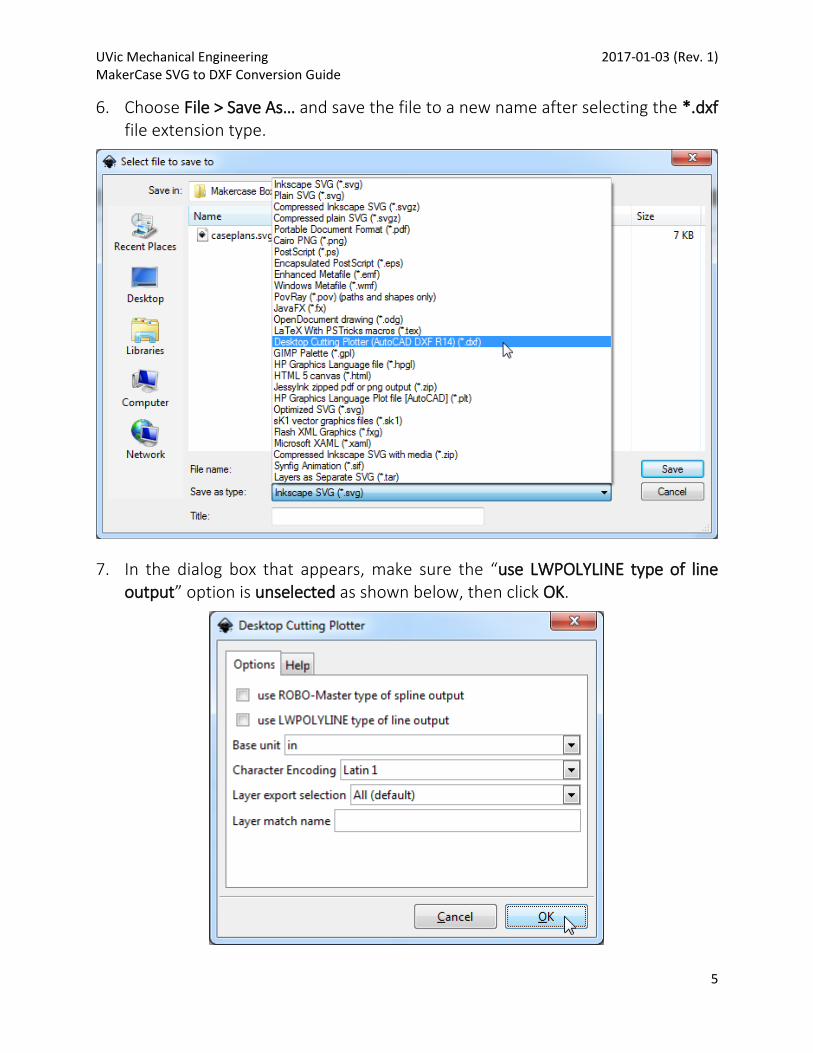
6. Choose File > Save As… and save the file to a new name after selecting the *.dxf file extension type.
7. In the dialog box that appears, make sure the “use LWPOLYLINE type of line output” option is unselected as shown below, then click OK.
UVic Mechanical Engineering 2017-01-03 (Rev. 1) MakerCase SVG to DXF Conversion Guide
6
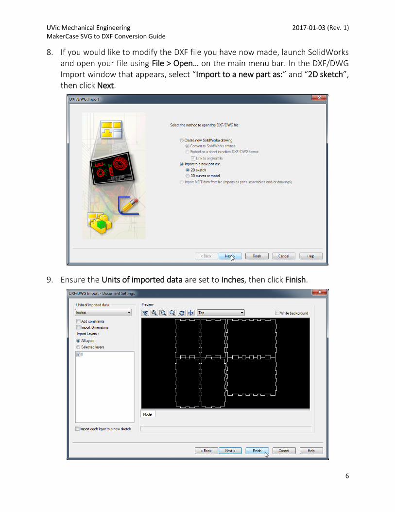
8. If you would like to modify the DXF file you have now made, launch SolidWorks and open your file using File > Open… on the main menu bar. In the DXF/DWG Import window that appears, select “Import to a new part as:” and “2D sketch”, then click Next.
9. Ensure the Units of imported data are set to Inches, then click Finish.
UVic Mechanical Engineering 2017-01-03 (Rev. 1) MakerCase SVG to DXF Conversion Guide
7
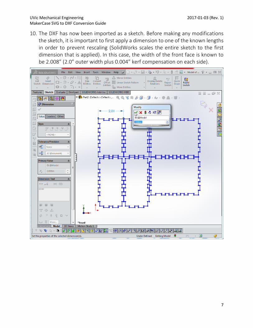
10. The DXF has now been imported as a sketch. Before making any modifications the sketch, it is important to first apply a dimension to one of the known lengths in order to prevent rescaling (SolidWorks scales the entire sketch to the first dimension that is applied). In this case, the width of the front face is known to be 2.008” (2.0” outer width plus 0.004” kerf compensation on each side).
UVic Mechanical Engineering 2017-01-03 (Rev. 1) MakerCase SVG to DXF Conversion Guide
8
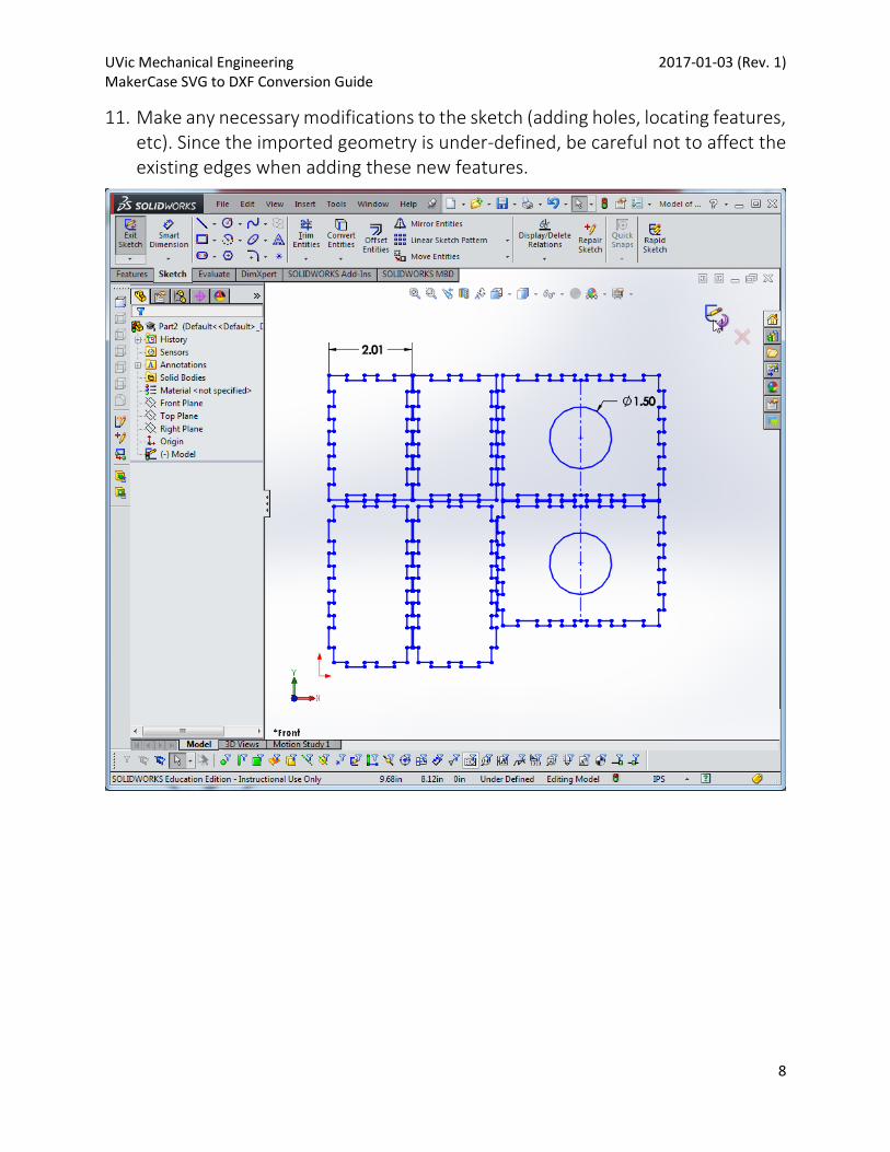
11. Make any necessary modifications to the sketch (adding holes, locating features, etc). Since the imported geometry is under-defined, be careful not to affect the existing edges when adding these new features.
UVic Mechanical Engineering 2017-01-03 (Rev. 1) MakerCase SVG to DXF Conversion Guide
9
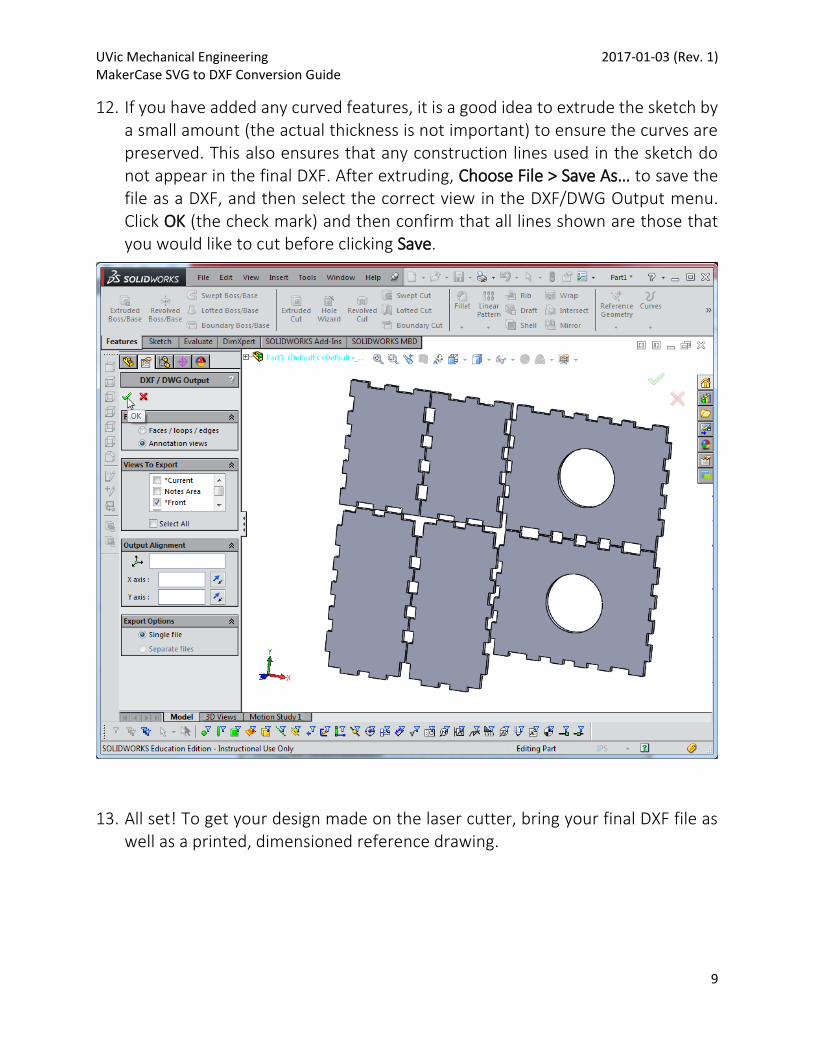
12. If you have added any curved features, it is a good idea to extrude the sketch by a small amount (the actual thickness is not important) to ensure the curves are preserved. This also ensures that any construction lines used in the sketch do not appear in the final DXF. After extruding, Choose File > Save As… to save the file as a DXF, and then select the correct view in the DXF/DWG Output menu. Click OK (the check mark) and then confirm that all lines shown are those that you would like to cut before clicking Save.
13. All set! To get your design made on the laser cutter, bring your final DXF file as well as a printed, dimensioned reference drawing.
![[MS-SVG]: Internet Explorer Scalable Vector Graphics (SVG ...interoperability.blob.core.windows.net/web/MS-SVG/[MS-SVG].pdf · Internet Explorer Scalable Vector Graphics (SVG) Standards](https://img.pdfslide.us/doc/110x75/5a6fc5167f8b9ac0538b6194/ms-svg-internet-explorer-scalable-vector-graphics-svg-interoperabilityblobcorewindowsnetwebms-svgms-svgpdfpdf.jpg)


![[MS-SVG]: Internet Explorer Scalable Vector Graphics (SVG ...MS-SVG].pdfGraphics (SVG) 1.1 Specification (Second Edition) [W3C-SVG1.1/2], W3C Recommendation published August 16, 2011](https://img.pdfslide.us/doc/110x75/5ee21471ad6a402d666cb6ad/ms-svg-internet-explorer-scalable-vector-graphics-svg-ms-svgpdf-graphics.jpg)
![interoperability.blob.core.windows.netinteroperability.blob.core.windows.net/web/MS-SVG/[MS … · Web view[MS-SVG]: Internet Explorer Scalable Vector Graphics (SVG) Standards Support](https://img.pdfslide.us/doc/110x75/5a6fc5167f8b9ac0538b61d3/interoperabilityblobcorewindowsnetinteroperabilityblobcorewindowsnetwebms-svgms.jpg)