Embed Size (px)
Citation preview
Make Your Own Fritzing Parts alearn.sparkfun.com tutorial
Available online at: http://sfe.io/t144
Contents
What is Fritzing?Download and InstallBreadboard ViewCreate a New PartCustom Breadboard SVGBreadboard View - Parts EditorSchematic ViewPCB ViewIcon ViewMetadataConnectors ViewExporting New PartResources and Going Further
What is Fritzing?
Fritzing is a great open source tool for anyone to teach, share, and prototype their electronicprojects! It allows you to design a schematic, and thus a part, which can then be added to veryprofessional-looking wiring diagrams. You can even design your own PCBs and have themfabricated from the files you design. Here at SparkFun, we use Fritzing in the classrooms, our hook-up guides, and any other place we need to show how to hook-up our boards to other hardware.
Page 1 of 28
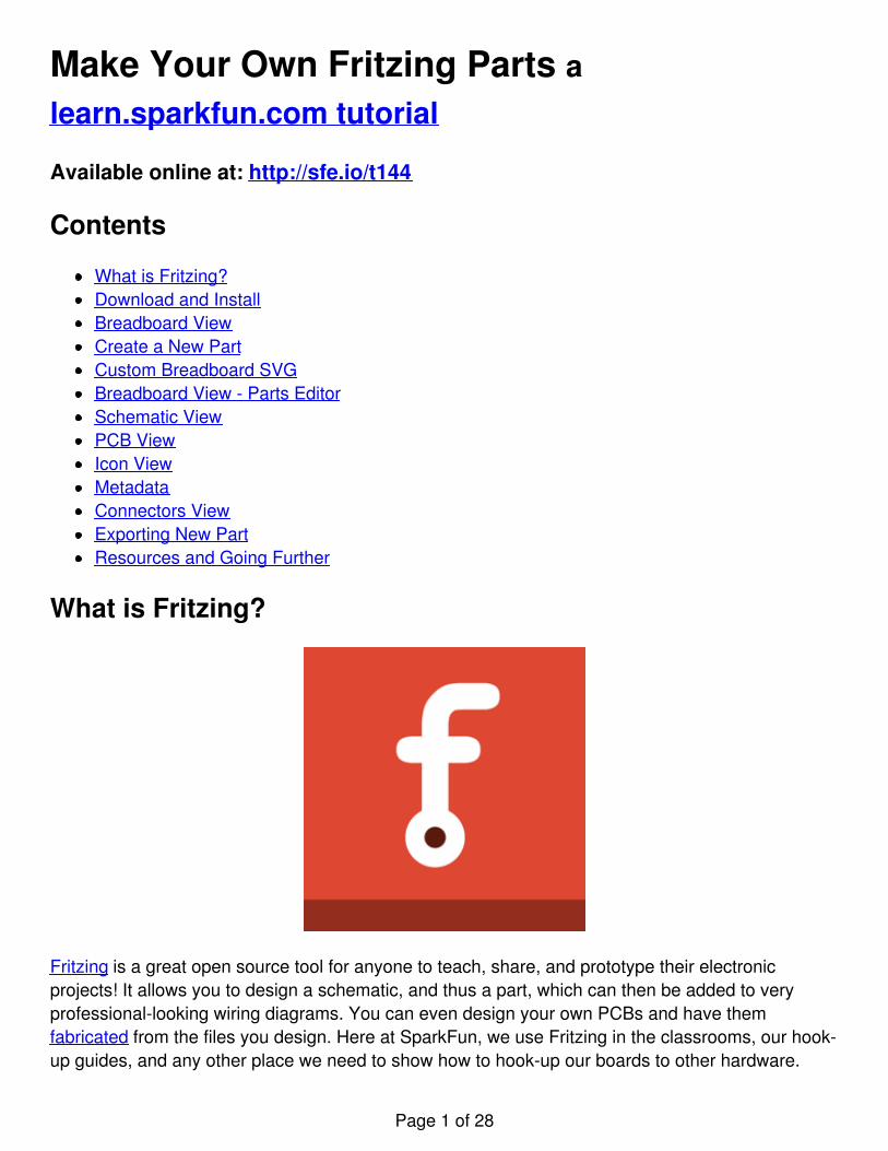
Fritzing example of the INA169 connected to an Arduino
The awesome thing about Fritzing is that you can make your own Fritzing parts for your project andshare with the community! This tutorial is going to go over how to make a custom Fritzing part inthe Fritzing (New) Parts Editor, starting from the beginning.
Do You Need to Make a Custom Fritzing Part?
Fritzing comes with tons of electronic parts already installed with the software. SparkFun also has aFritzing Github repo for housing parts we’ve created not already in Fritzing. Before creating yourown part, double check to see if it exists in those two locations or if another Fritzing user alreadymade the part you need on the Fritzing forum. It will save you a lot of time if the part is alreadymade! However, if you’re certain that the part you need doesn’t live in Fritzing land already, read on!
Suggested Reading
Page 2 of 28
This tutorial assumes that you are already familiar with Adobe Illustrator, Inscape, or both. Usingthese programs is beyond the scope of this tutorial. If you need more info on how to use eithwer ofthese programs, their respective websites should have lots of tutorials and guides on how to getstarted with vector graphics. If that fails, there’s always Google.
Here are other related tutorials you may want to check out before reading this one:
PCB BasicsIntegrated Circuits (ICs)Connector BasicsUsing GitHubHow to Use a BreadboardHow to Read a Schematic
Download and Install
You will need to download and install the following software in order to follow along and make yourown custom Fritzing part.
Please Note: If you only need to make a basic IC, Fritzing (New) Parts Editor allows you to makecustom ICs easily, and you won’t need to download a vector graphic editor. You can still followalong, since this tutorial will be building off a custom IC in the Fritzing (New) Parts Editor.
Fritzing
Go to the download page on the Fritzing site to download the latest Fritzing version for your OS.Find where you want to put the Fritzing application on your hard drive, and unzip the Fritzing folderin that location.
Vector Graphics Editor
There is a lot of different types of vector graphics editors out there. The vector graphics editors weuse here at SparkFun are Adobe Illustrator and Inkscape. Choose the one you are the most familiarand comfortable with. If you don’t have a vector graphics editor, Inkscape is a great open sourcechoice, and it is free.
Inkscape
Page 3 of 28
Go to the Inkscape download page and download the appropriate Official Release Package for yourcomputer.
Windows Users: Double click on the executable. Follow along the Inkscape Setup Wizard.
Mac OS X Users: Follow along the newest instructions on the Inkscape site.
Adobe Illustrator
Adobe Illustrator is not free, but if you already have the Adobe Creative Cloud you can download it.You can also purchase an Illustrator monthly membership.
Please Note: We have no affiliation with Adobe and are only promoting Illustrator because it is agreat piece of software that works well for what we need in this tutorial.
Other Downloads
Fritzing Fonts and Templates
Fritzing uses the OCR-A font for ICs. For all the other parts you can use OCR-A and Droid Sansfonts. Fritzing has fonts and templates available for download on their site. You will need todownload Fritzing's Graphic Standards to follow this tutorial. Go to their template download page,and download the Fritzing's Graphic Standards folder. After you download their zip file, you willneed to make sure to unzip the folder, and place anywhere on your computer. You will want to
Page 4 of 28
install the fonts on your computer.
SparkFun Fritzing Example Templates
This tutorial will reference the SparkFun Fritzing Example Templates a lot. If you are making aFritzing part for a SparkFun board or want a starting point, download this set of example templatesfrom the SparkFun Fritzing Parts Github repo. The SparkFun Fritzing templates will have thistutorial's example, SparkFun T5403 Barometer Breakout SVG, files to compare and work with.
Breadboard View
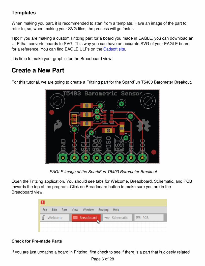
When the Fritzing starts up, you should be in the Welcome view. You will want to go to Breadboardview.
There is two main steps you will need to do in Breadboard view. First, create your breadboard SVG,and upload it. Fritzing prefers using SVG format, so your images look great when you are zoomedin and out! Second, you’ll need to change the connector pins.
Please note: If you are only making a basic IC you can skip to Editing Breadboard View section ofthis tutorial.
Fritzing Graphic Standards
On the Fritzing website, there are a lot of graphic standards to follow. It is a great idea to follow thegraphic standards that way your parts match other Fritzing parts.
Page 5 of 28
Templates
When making you part, it is recommended to start from a template. Have an image of the part torefer to, so, when making your SVG files, the process will go faster.
Tip: If you are making a custom Fritzing part for a board you made in EAGLE, you can download anULP that converts boards to SVG. This way you can have an accurate SVG of your EAGLE boardfor a reference. You can find EAGLE ULPs on the Cadsoft site.
It is time to make your graphic for the Breadboard view!
Create a New Part
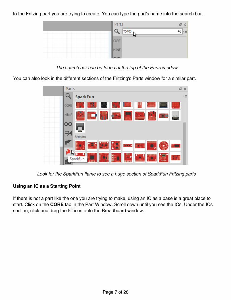
For this tutorial, we are going to create a Fritzing part for the SparkFun T5403 Barometer Breakout.
EAGLE image of the SparkFun T5403 Barometer Breakout
Open the Fritzing application. You should see tabs for Welcome, Breadboard, Schematic, and PCBtowards the top of the program. Click on Breadboard button to make sure you are in theBreadboard view.
Check for Pre-made Parts
If you are just updating a board in Fritzing, first check to see if there is a part that is closely related
Page 6 of 28
to the Fritzing part you are trying to create. You can type the part's name into the search bar.
The search bar can be found at the top of the Parts window
You can also look in the different sections of the Fritzing's Parts window for a similar part.
Look for the SparkFun flame to see a huge section of SparkFun Fritzing parts
Using an IC as a Starting Point
If there is not a part like the one you are trying to make, using an IC as a base is a great place tostart. Click on the CORE tab in the Part Window. Scroll down until you see the ICs. Under the ICssection, click and drag the IC icon onto the Breadboard window.
Page 7 of 28
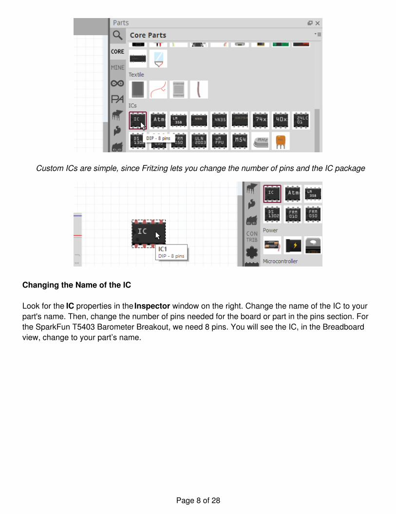
Custom ICs are simple, since Fritzing lets you change the number of pins and the IC package
Changing the Name of the IC
Look for the IC properties in the Inspector window on the right. Change the name of the IC to yourpart's name. Then, change the number of pins needed for the board or part in the pins section. Forthe SparkFun T5403 Barometer Breakout, we need 8 pins. You will see the IC, in the Breadboardview, change to your part’s name.
Page 8 of 28
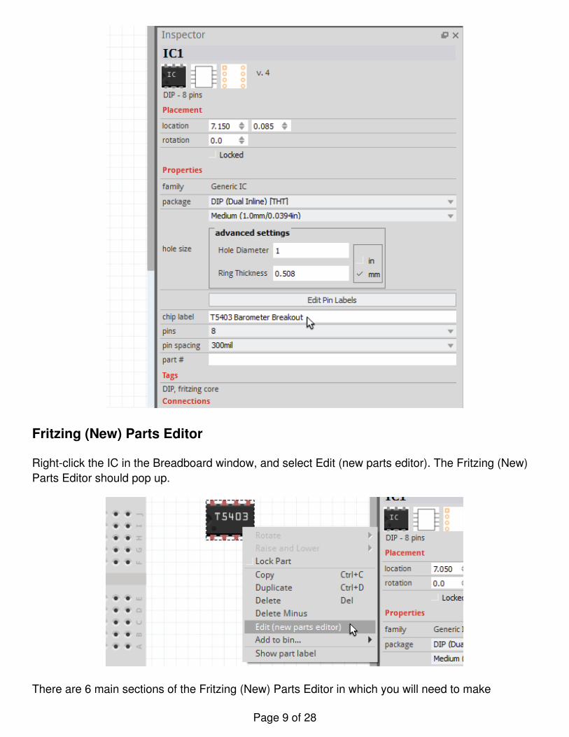
Fritzing (New) Parts Editor
Right-click the IC in the Breadboard window, and select Edit (new parts editor). The Fritzing (New)Parts Editor should pop up.
There are 6 main sections of the Fritzing (New) Parts Editor in which you will need to make
Page 9 of 28
changes. Those are:
BreadboardSchematicPCBIconMetadataConnectors
There really isn't an order you need to follow. After making a couple different custom parts you willprobably end up starting in one view before the others. In this tutorial, we’re just going to go downthe list.
Author note: I found, for boards with a large number of pins, that starting off in the Connectors viewsaves a little bit more time, since you can go down the list to name the connector pins faster.
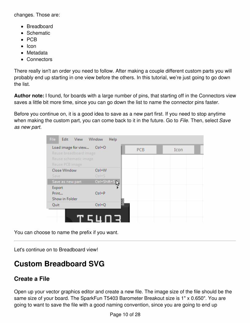
Before you continue on, it is a good idea to save as a new part first. If you need to stop anytimewhen making the custom part, you can come back to it in the future. Go to File. Then, select Saveas new part.
You can choose to name the prefix if you want.
Let's continue on to Breadboard view!
Custom Breadboard SVG
Create a File
Open up your vector graphics editor and create a new file. The image size of the file should be thesame size of your board. The SparkFun T5403 Barometer Breakout size is 1" x 0.650". You aregoing to want to save the file with a good naming convention, since you are going to end up
Page 10 of 28
needing 3 different svg files when creating your Fritzing part.
Illustrator Users: You can save by going to File->Save As, saving as a SVG, and hitting Save.
For this example the Breadboard SVG is named:SFE_T5403_Barometer_Breakout_breadboard.svg
Use Templates as References
To compare the different layers and groups, you can open up the FritzingBreadboardViewGraphic_Template.svg file found in the Fritzing Fonts and Template folder youdownloaded earlier. You can also open the example SparkFun T5403 Barometer Breakoutbreadboard SVG template file from the SparkFun Fritzing Parts Github repo.
You can see with the example templates how you can kept the layers organized. For the SparkFunT5403 Barometer Breakout, there is a “breadboard” group. Inside that breadboard group it will havethe group of parts, copper layers, silkscreen group, and the board path.
Tips for Making Your Custom Breadboard Graphic
You are now able to create your custom part’s breadboard graphic. Here are some helpful tips!
Follow the Fritzing Graphic Standards
Here are some main color standards for Breadboard images:
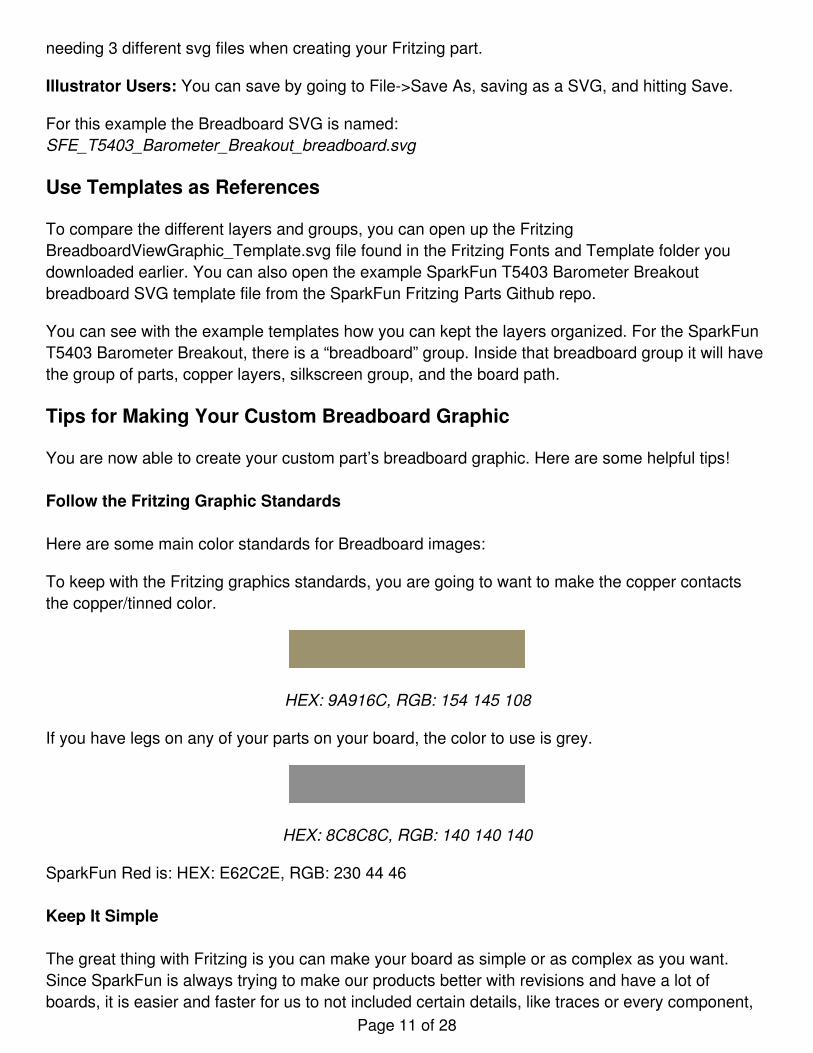
To keep with the Fritzing graphics standards, you are going to want to make the copper contactsthe copper/tinned color.
HEX: 9A916C, RGB: 154 145 108
If you have legs on any of your parts on your board, the color to use is grey.
HEX: 8C8C8C, RGB: 140 140 140
SparkFun Red is: HEX: E62C2E, RGB: 230 44 46
Keep It Simple
The great thing with Fritzing is you can make your board as simple or as complex as you want.Since SparkFun is always trying to make our products better with revisions and have a lot ofboards, it is easier and faster for us to not included certain details, like traces or every component,
Page 11 of 28
on our boards. That way if there is a new change with the board, like a resistor value change, wedon't have to go in and change that resistor in the Fritzing part. Focusing more on the importantcomponents, like ICs, might be a better way to spend your tine. It will still look nice, but less work!
Use Components That Already Exist
If you need an SMD LED on your board that is already in Fritzing, go ahead and use it! This willsave you time and keep the all the Fritzing parts having the same look and feel. If you create acustom board with components that others can use, you can share them on the Fritzing site, soothers can use too! Make sure to organize the component graphics nicely in the vector graphicseditor you are using, so the parts are easy to find when using on future boards.
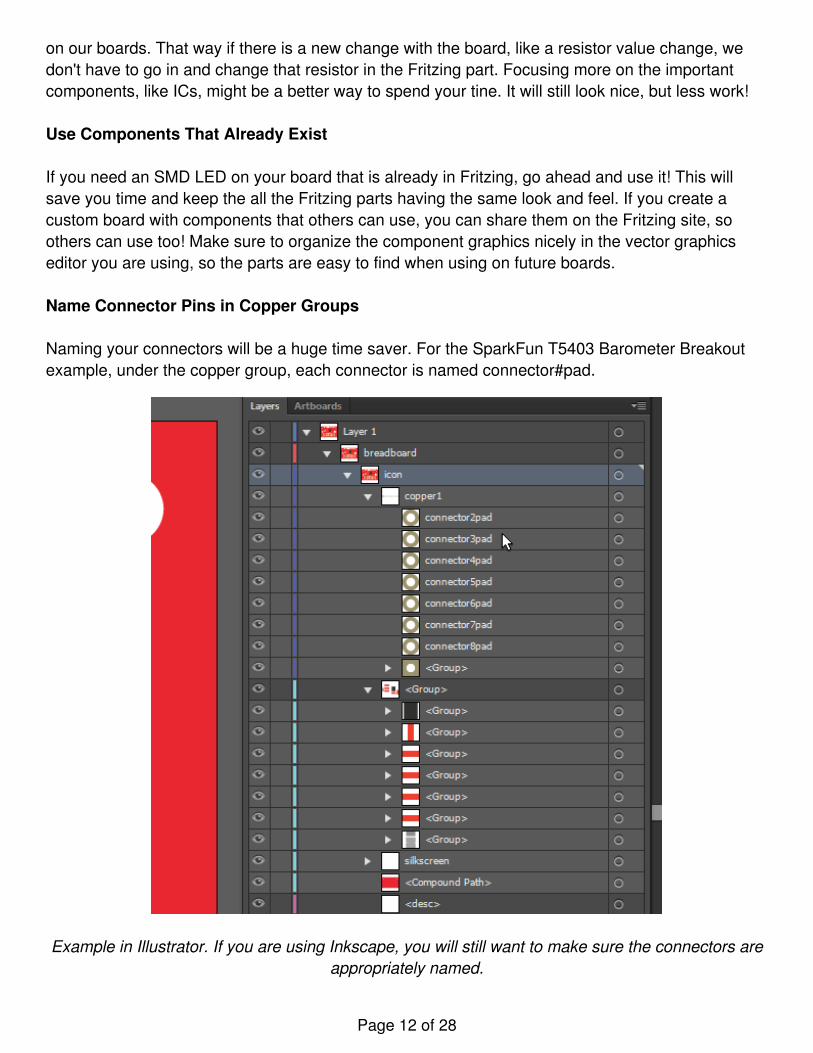
Name Connector Pins in Copper Groups
Naming your connectors will be a huge time saver. For the SparkFun T5403 Barometer Breakoutexample, under the copper group, each connector is named connector#pad.
Example in Illustrator. If you are using Inkscape, you will still want to make sure the connectors areappropriately named.
Page 12 of 28
Use the ORC-A or Droid Sans Fonts.
Stick with the Fritzing fonts to kept all Fritzing parts looking alike. It is suggested that the standardfont size is 5pt. However, there will be times you won't have space for smaller boards. You won'twant to go lower then 3pt, because it starts to become harder to see without zooming in. On theFritzing site they mention using black as the font color. Whatever your silkscreen color is tends tolook better. For this example we are using white, since that is the breakout board's silkscreen colorand it is easier to read against a red background.
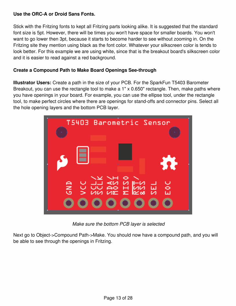
Create a Compound Path to Make Board Openings See-through
Illustrator Users: Create a path in the size of your PCB. For the SparkFun T5403 BarometerBreakout, you can use the rectangle tool to make a 1" x 0.650" rectangle. Then, make paths whereyou have openings in your board. For example, you can use the ellipse tool, under the rectangletool, to make perfect circles where there are openings for stand-offs and connector pins. Select allthe hole opening layers and the bottom PCB layer.
Make sure the bottom PCB layer is selected
Next go to Object->Compound Path->Make. You should now have a compound path, and you willbe able to see through the openings in Fritzing.
Page 13 of 28
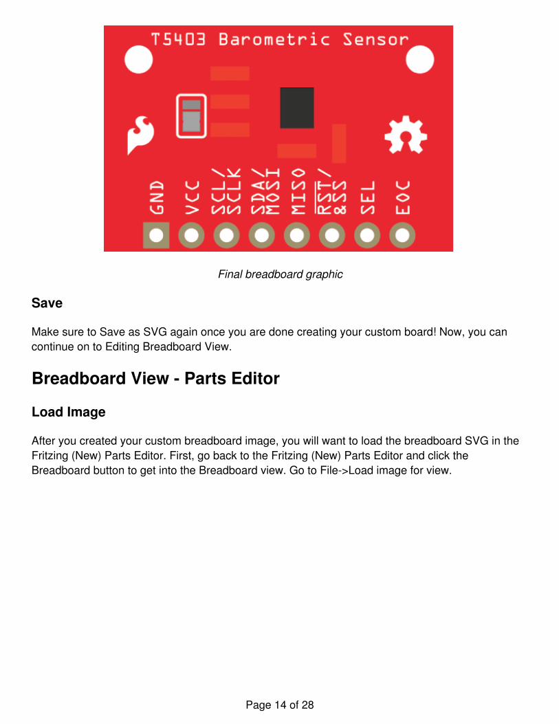
Final breadboard graphic
Save
Make sure to Save as SVG again once you are done creating your custom board! Now, you cancontinue on to Editing Breadboard View.
Breadboard View - Parts Editor
Load Image
After you created your custom breadboard image, you will want to load the breadboard SVG in theFritzing (New) Parts Editor. First, go back to the Fritzing (New) Parts Editor and click theBreadboard button to get into the Breadboard view. Go to File->Load image for view.
Page 14 of 28
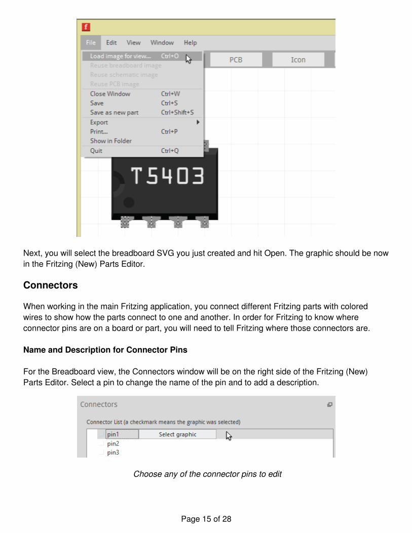
Next, you will select the breadboard SVG you just created and hit Open. The graphic should be nowin the Fritzing (New) Parts Editor.
Connectors
When working in the main Fritzing application, you connect different Fritzing parts with coloredwires to show how the parts connect to one and another. In order for Fritzing to know whereconnector pins are on a board or part, you will need to tell Fritzing where those connectors are.
Name and Description for Connector Pins
For the Breadboard view, the Connectors window will be on the right side of the Fritzing (New)Parts Editor. Select a pin to change the name of the pin and to add a description.
Choose any of the connector pins to edit
Page 15 of 28
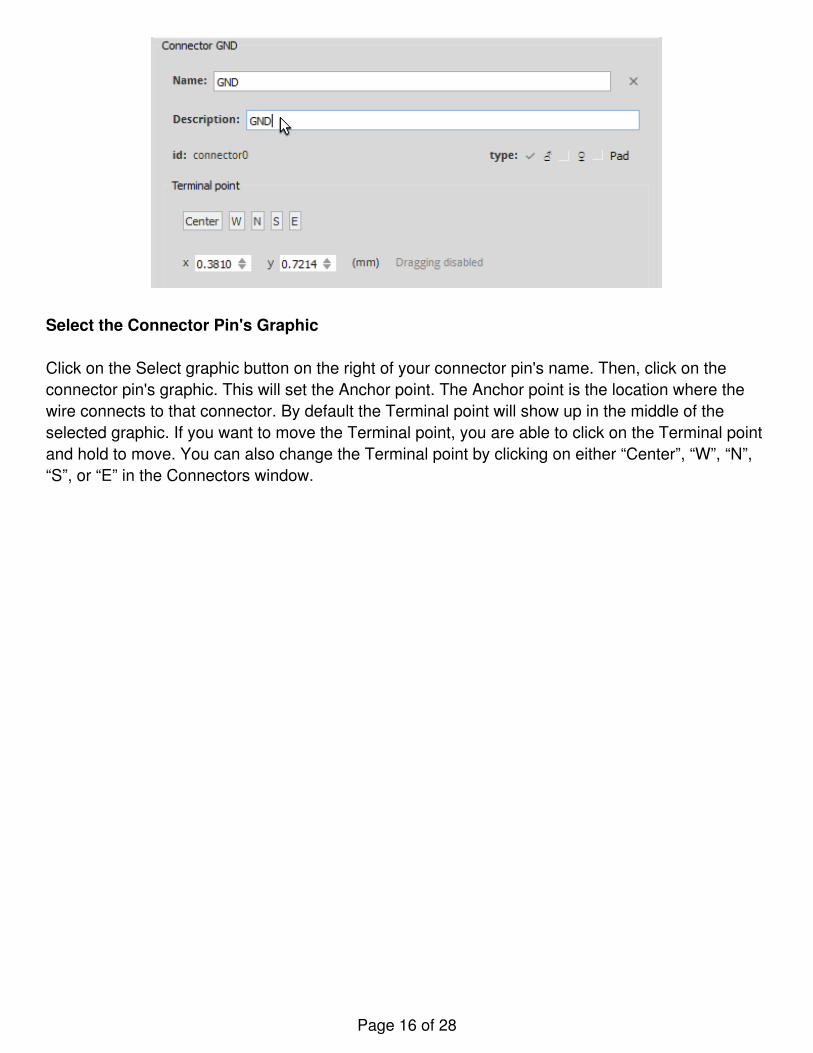
Select the Connector Pin's Graphic
Click on the Select graphic button on the right of your connector pin's name. Then, click on theconnector pin's graphic. This will set the Anchor point. The Anchor point is the location where thewire connects to that connector. By default the Terminal point will show up in the middle of theselected graphic. If you want to move the Terminal point, you are able to click on the Terminal pointand hold to move. You can also change the Terminal point by clicking on either “Center”, “W”, “N”,“S”, or “E” in the Connectors window.
Page 16 of 28
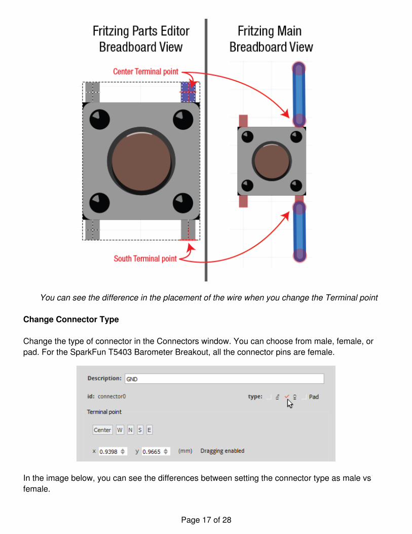
You can see the difference in the placement of the wire when you change the Terminal point
Change Connector Type
Change the type of connector in the Connectors window. You can choose from male, female, orpad. For the SparkFun T5403 Barometer Breakout, all the connector pins are female.
In the image below, you can see the differences between setting the connector type as male vsfemale.
Page 17 of 28
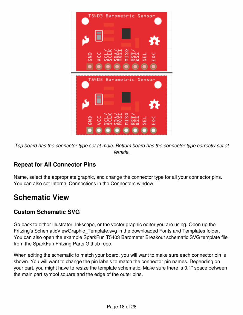
Top board has the connector type set at male. Bottom board has the connector type correctly set atfemale.
Repeat for All Connector Pins
Name, select the appropriate graphic, and change the connector type for all your connector pins.You can also set Internal Connections in the Connectors window.
Schematic View
Custom Schematic SVG
Go back to either Illustrator, Inkscape, or the vector graphic editor you are using. Open up theFritzing's SchematicViewGraphic_Template.svg in the downloaded Fonts and Templates folder.You can also open the example SparkFun T5403 Barometer Breakout schematic SVG template filefrom the SparkFun Fritzing Parts Github repo.
When editing the schematic to match your board, you will want to make sure each connector pin isshown. You will want to change the pin labels to match the connector pin names. Depending onyour part, you might have to resize the template schematic. Make sure there is 0.1” space betweenthe main part symbol square and the edge of the outer pins.
Page 18 of 28
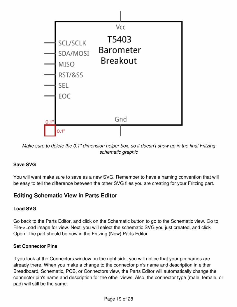
Make sure to delete the 0.1" dimension helper box, so it doesn’t show up in the final Fritzingschematic graphic
Save SVG
You will want make sure to save as a new SVG. Remember to have a naming convention that willbe easy to tell the difference between the other SVG files you are creating for your Fritzing part.
Editing Schematic View in Parts Editor
Load SVG
Go back to the Parts Editor, and click on the Schematic button to go to the Schematic view. Go toFile->Load image for view. Next, you will select the schematic SVG you just created, and clickOpen. The part should be now in the Fritzing (New) Parts Editor.
Set Connector Pins
If you look at the Connectors window on the right side, you will notice that your pin names arealready there. When you make a change to the connector pin's name and description in eitherBreadboard, Schematic, PCB, or Connectors view, the Parts Editor will automatically change theconnector pin's name and description for the other views. Also, the connector type (male, female, orpad) will still be the same.
Page 19 of 28
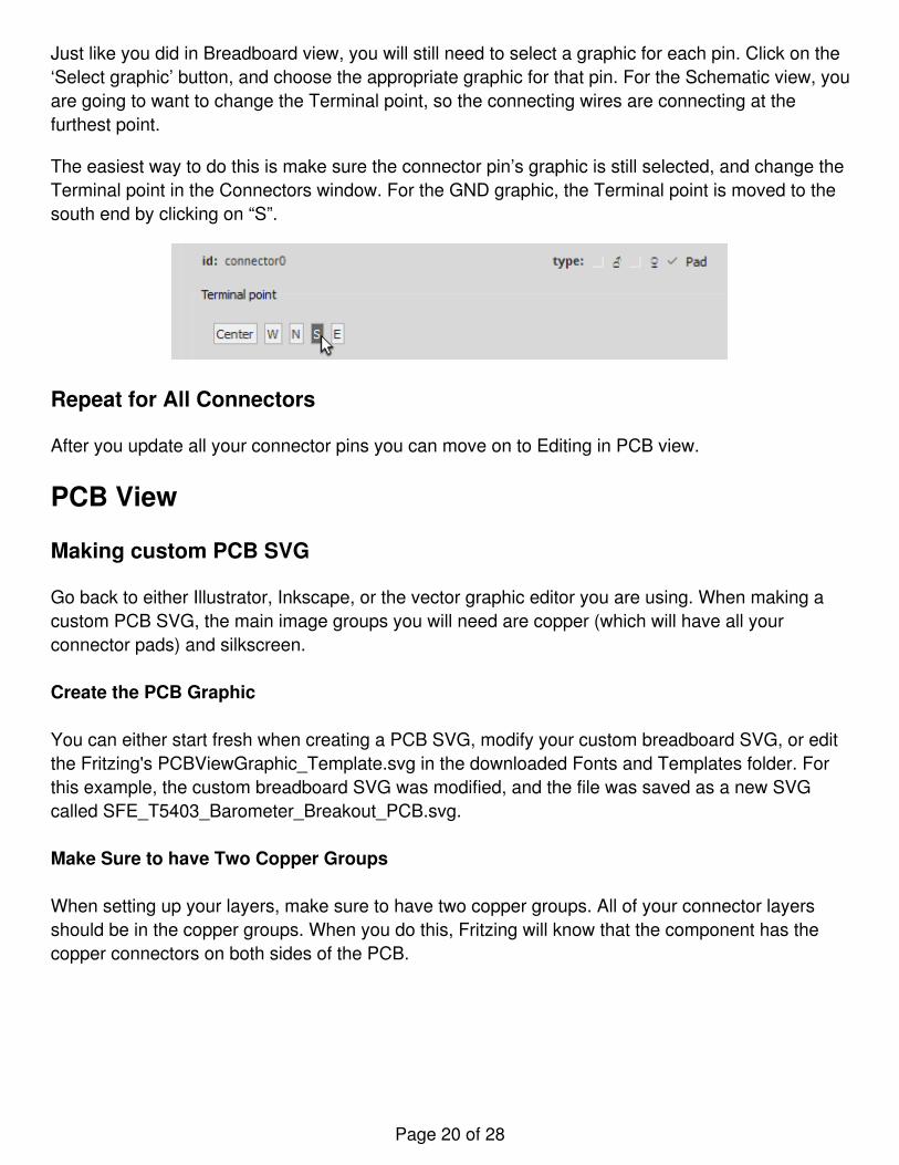
Just like you did in Breadboard view, you will still need to select a graphic for each pin. Click on the‘Select graphic’ button, and choose the appropriate graphic for that pin. For the Schematic view, youare going to want to change the Terminal point, so the connecting wires are connecting at thefurthest point.
The easiest way to do this is make sure the connector pin’s graphic is still selected, and change theTerminal point in the Connectors window. For the GND graphic, the Terminal point is moved to thesouth end by clicking on “S”.
Repeat for All Connectors
After you update all your connector pins you can move on to Editing in PCB view.
PCB View
Making custom PCB SVG
Go back to either Illustrator, Inkscape, or the vector graphic editor you are using. When making acustom PCB SVG, the main image groups you will need are copper (which will have all yourconnector pads) and silkscreen.
Create the PCB Graphic
You can either start fresh when creating a PCB SVG, modify your custom breadboard SVG, or editthe Fritzing's PCBViewGraphic_Template.svg in the downloaded Fonts and Templates folder. Forthis example, the custom breadboard SVG was modified, and the file was saved as a new SVGcalled SFE_T5403_Barometer_Breakout_PCB.svg.
Make Sure to have Two Copper Groups
When setting up your layers, make sure to have two copper groups. All of your connector layersshould be in the copper groups. When you do this, Fritzing will know that the component has thecopper connectors on both sides of the PCB.
Page 20 of 28
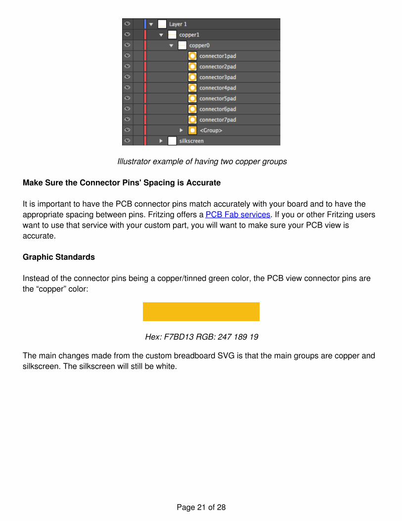
Illustrator example of having two copper groups
Make Sure the Connector Pins' Spacing is Accurate
It is important to have the PCB connector pins match accurately with your board and to have theappropriate spacing between pins. Fritzing offers a PCB Fab services. If you or other Fritzing userswant to use that service with your custom part, you will want to make sure your PCB view isaccurate.
Graphic Standards
Instead of the connector pins being a copper/tinned green color, the PCB view connector pins arethe “copper” color:
Hex: F7BD13 RGB: 247 189 19
The main changes made from the custom breadboard SVG is that the main groups are copper andsilkscreen. The silkscreen will still be white.
Page 21 of 28
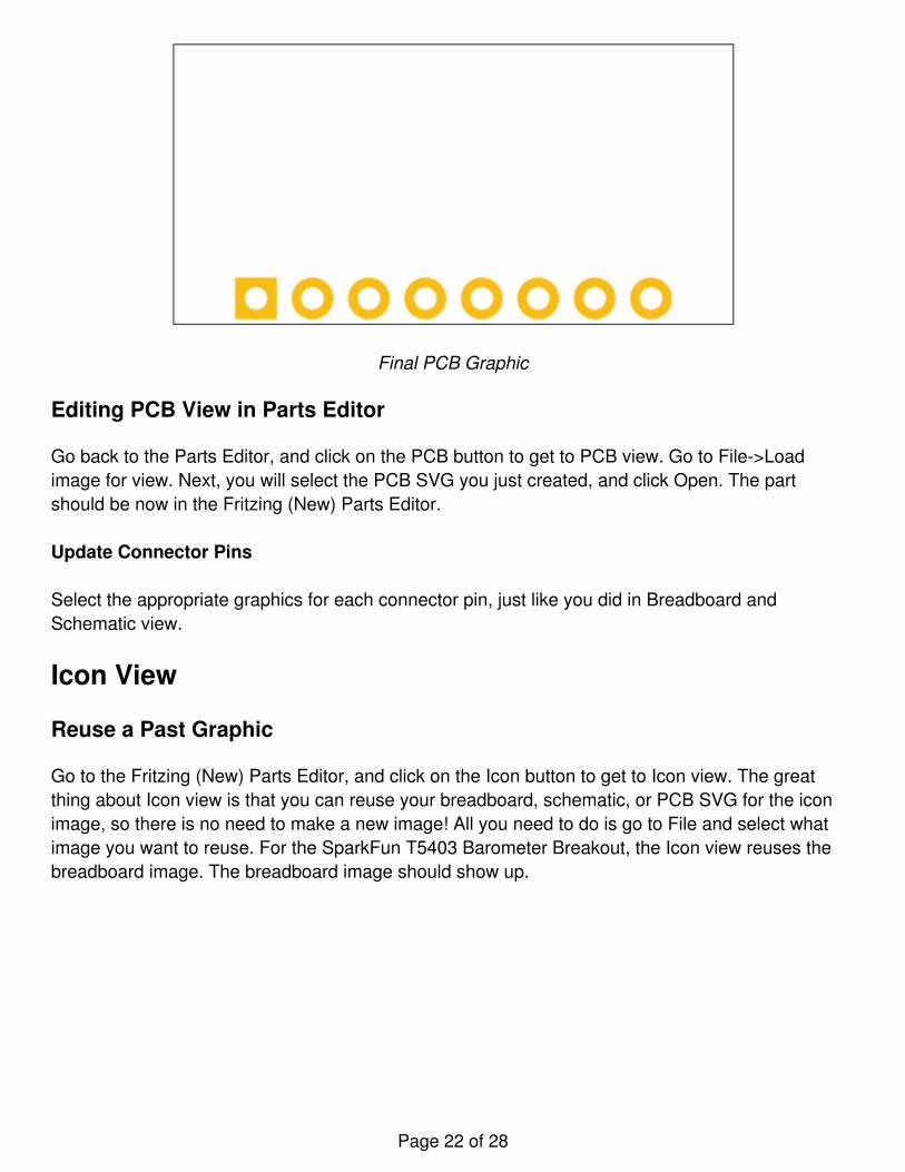
Final PCB Graphic
Editing PCB View in Parts Editor
Go back to the Parts Editor, and click on the PCB button to get to PCB view. Go to File->Loadimage for view. Next, you will select the PCB SVG you just created, and click Open. The partshould be now in the Fritzing (New) Parts Editor.
Update Connector Pins
Select the appropriate graphics for each connector pin, just like you did in Breadboard andSchematic view.
Icon View
Reuse a Past Graphic
Go to the Fritzing (New) Parts Editor, and click on the Icon button to get to Icon view. The greatthing about Icon view is that you can reuse your breadboard, schematic, or PCB SVG for the iconimage, so there is no need to make a new image! All you need to do is go to File and select whatimage you want to reuse. For the SparkFun T5403 Barometer Breakout, the Icon view reuses thebreadboard image. The breadboard image should show up.
Page 22 of 28
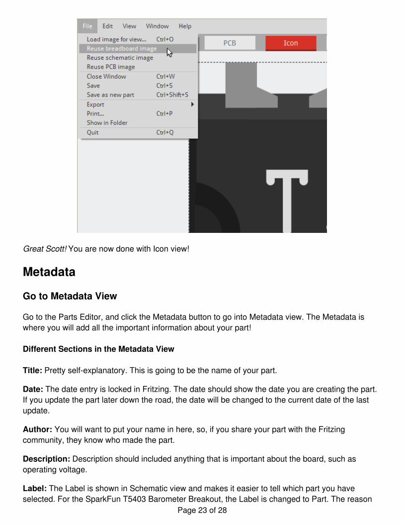
Great Scott! You are now done with Icon view!
Metadata
Go to Metadata View
Go to the Parts Editor, and click the Metadata button to go into Metadata view. The Metadata iswhere you will add all the important information about your part!
Different Sections in the Metadata View
Title: Pretty self-explanatory. This is going to be the name of your part.
Date: The date entry is locked in Fritzing. The date should show the date you are creating the part.If you update the part later down the road, the date will be changed to the current date of the lastupdate.
Author: You will want to put your name in here, so, if you share your part with the Fritzingcommunity, they know who made the part.
Description: Description should included anything that is important about the board, such asoperating voltage.
Label: The Label is shown in Schematic view and makes it easier to tell which part you haveselected. For the SparkFun T5403 Barometer Breakout, the Label is changed to Part. The reason
Page 23 of 28
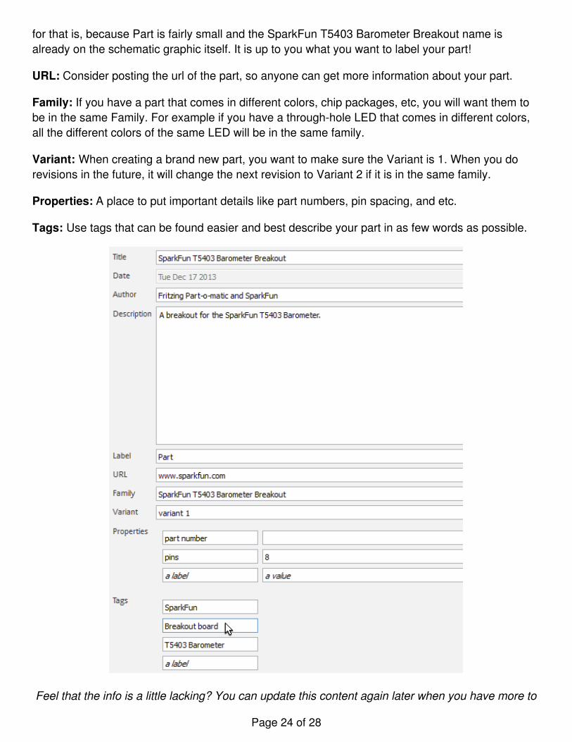
for that is, because Part is fairly small and the SparkFun T5403 Barometer Breakout name isalready on the schematic graphic itself. It is up to you what you want to label your part!
URL: Consider posting the url of the part, so anyone can get more information about your part.
Family: If you have a part that comes in different colors, chip packages, etc, you will want them tobe in the same Family. For example if you have a through-hole LED that comes in different colors,all the different colors of the same LED will be in the same family.
Variant: When creating a brand new part, you want to make sure the Variant is 1. When you dorevisions in the future, it will change the next revision to Variant 2 if it is in the same family.
Properties: A place to put important details like part numbers, pin spacing, and etc.
Tags: Use tags that can be found easier and best describe your part in as few words as possible.
Feel that the info is a little lacking? You can update this content again later when you have more to
Page 24 of 28
write.
Connectors View
Go to Connectors view
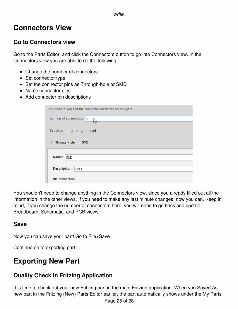
Go to the Parts Editor, and click the Connectors button to go into Connectors view. In theConnectors view you are able to do the following:
Change the number of connectorsSet connector typeSet the connector pins as Through-hole or SMDName connector pinsAdd connector pin descriptions
You shouldn't need to change anything in the Connectors view, since you already filled out all theinformation in the other views. If you need to make any last minute changes, now you can. Keep inmind, if you change the number of connectors here, you will need to go back and updateBreadboard, Schematic, and PCB views.
Save
Now you can save your part! Go to File>Save
Continue on to exporting part!
Exporting New Part
Quality Check in Fritzing Application
It is time to check out your new Fritzing part in the main Fritzing application. When you Saved Asnew part in the Fritzing (New) Parts Editor earlier, the part automatically shows under the My Parts
Page 25 of 28
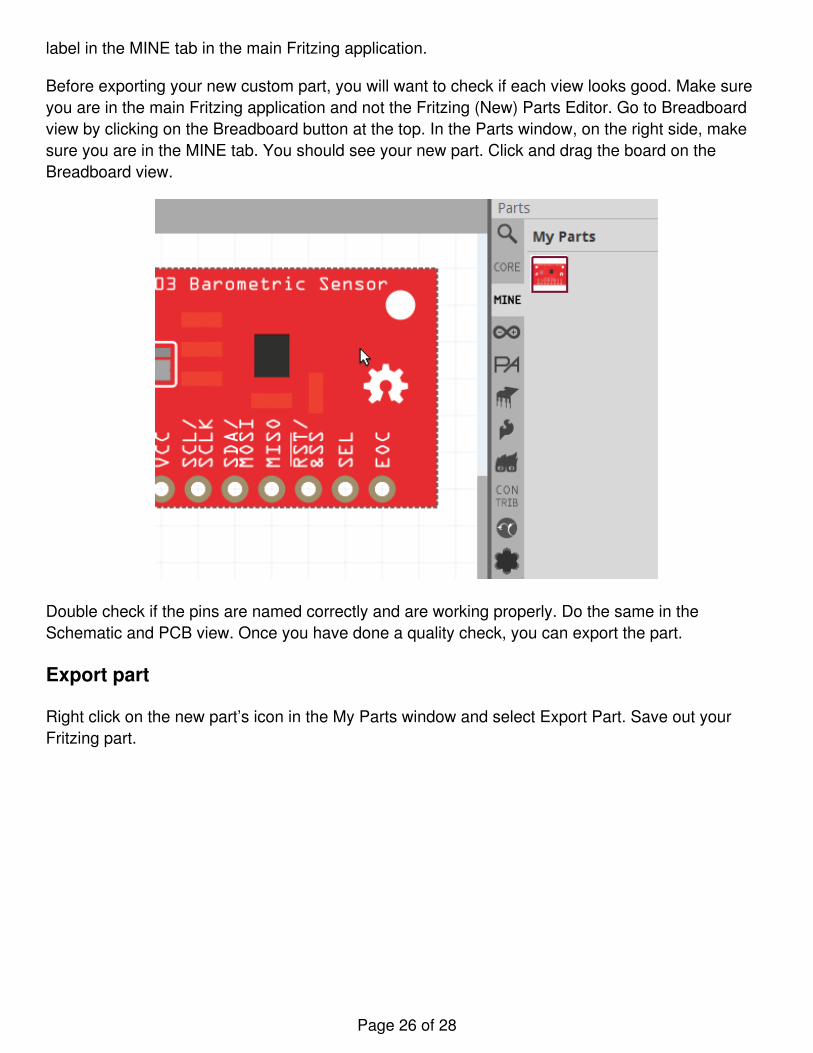
label in the MINE tab in the main Fritzing application.
Before exporting your new custom part, you will want to check if each view looks good. Make sureyou are in the main Fritzing application and not the Fritzing (New) Parts Editor. Go to Breadboardview by clicking on the Breadboard button at the top. In the Parts window, on the right side, makesure you are in the MINE tab. You should see your new part. Click and drag the board on theBreadboard view.
Double check if the pins are named correctly and are working properly. Do the same in theSchematic and PCB view. Once you have done a quality check, you can export the part.
Export part
Right click on the new part’s icon in the My Parts window and select Export Part. Save out yourFritzing part.
Page 26 of 28
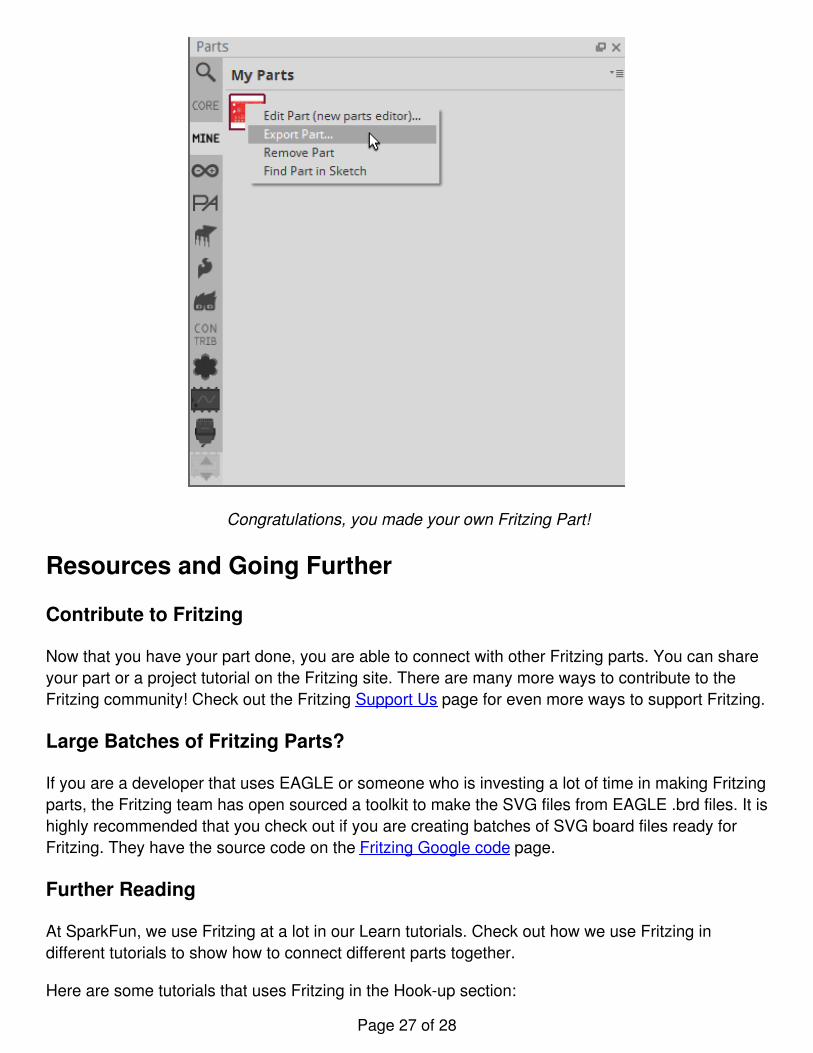
Congratulations, you made your own Fritzing Part!
Resources and Going Further
Contribute to Fritzing
Now that you have your part done, you are able to connect with other Fritzing parts. You can shareyour part or a project tutorial on the Fritzing site. There are many more ways to contribute to theFritzing community! Check out the Fritzing Support Us page for even more ways to support Fritzing.
Large Batches of Fritzing Parts?
If you are a developer that uses EAGLE or someone who is investing a lot of time in making Fritzingparts, the Fritzing team has open sourced a toolkit to make the SVG files from EAGLE .brd files. It ishighly recommended that you check out if you are creating batches of SVG board files ready forFritzing. They have the source code on the Fritzing Google code page.
Further Reading
At SparkFun, we use Fritzing at a lot in our Learn tutorials. Check out how we use Fritzing indifferent tutorials to show how to connect different parts together.
Here are some tutorials that uses Fritzing in the Hook-up section:
Page 27 of 28
INA169 Breakout Board Hookup GuideTilt-a-Whirl Hookup Guide
If you want to learn more about designing your own PCBs with other software, visit these tutorials:
Install and Setup EAGLEUsing EAGLE: SchematicUsing EAGLE: Board Layout
For vector images of parts, try the Electronic Graphics Resources so that you do not have to makea part from scratch.
Electronic Graphics Resources
February 6, 2014
Illustrator file with a variety of electronics images and icons. Made by Adam Meyer of bildr.org.Favorited Favorite 3
learn.sparkfun.com | CC BY-SA 3.0 | SparkFun Electronics | Niwot, Colorado
Page 28 of 28