Embed Size (px)
Citation preview

HOSOKAWA MICRON POWDER SYSTEMS
10 Chatham Road, Summit, NJ 07901 Tel. (908) 273-6360 Fax (908) 273-7432
Mikro Air Jet Sieve®
MAJSx
Operations and Maintenance
Manual
Process Technologies for Tomorrow
Be sure to read this manual before using this product.
2
OPERATING & MAINTENANCE MANUAL
Mikro Air Jet Sieve®
MIKRO AIR JET SIEVE® - Model MAJSx
Document Number: (691463.160831)
Revision Date Description
Issue August 31, 2016 Issue
3
OPERATING & MAINTENANCE MANUAL
Mikro Air Jet Sieve®
(1) Reproduction of this manual in part or in whole is strictly prohibited without prior permission
from Hosokawa Micron Powder Systems.
(2) The contents of this manual are subject to change without notice.
(3) The contents of this manual have been carefully prepared. If you have any questions, find
errors or omissions, please contact Hosokawa Micron Powder Systems.
(4) Hosokawa Micron Powder Systems does not permit the improper use or handling of this
product by a third party only Hosokawa Micron Powder Systems service personnel are
authorized to repair or modify this product. Note that Hosokawa Micron Powder Systems
assumes no responsibility for damage or injury attributable to repairs, changes, etc.
performed by a third party.
(5) Hosokawa Micron Powder Systems assumes no responsibility for damages or injury resulting
from the attaching, using options or consumables other than Hosokawa Micron Powder
Systems genuine qualified parts.
(6) The software of this product is owned by Hosokawa Micron Powder Systems and copyright
protected. Copying the software and/or instruction manual in part or whole without permission
from Hosokawa Micron Powder Systems is prohibited.
(7) The MAJSx was design for use with the Hosokawa Micron Test Sieve Screens, while certain
manufactures screens can and do fit the instrument, Hosokawa Micron Powder Systems
cannot guarantee operational results and is not responsible should any damage occur.
(8) The warranty period of this machine is one (1) year from the date of shipment. Any
Dismantling, Tampering “Opening” or “Removal” of Fixed Components will
VOID the Warranty, unless specified herein.
This Instruction Manual describes the proper, safe, operation of the Hosokawa Micron Product. It
is important that this Instruction Manual be read and fully understood before equipment
installation, operation, maintenance and/or inspection of this instrument. Especially, complete
understanding of the warning labels, as contained in this manual for safe operation of this
instrument.
Prediction of all possible operation hazards as defined in the manual is impossible however; the
dangers can be minimized by following the instructions described in this manual. Operate this
device with great care and make every endeavor to avoid any accident or damage to the device.
Notice
Important
4
OPERATING & MAINTENANCE MANUAL
Mikro Air Jet Sieve®
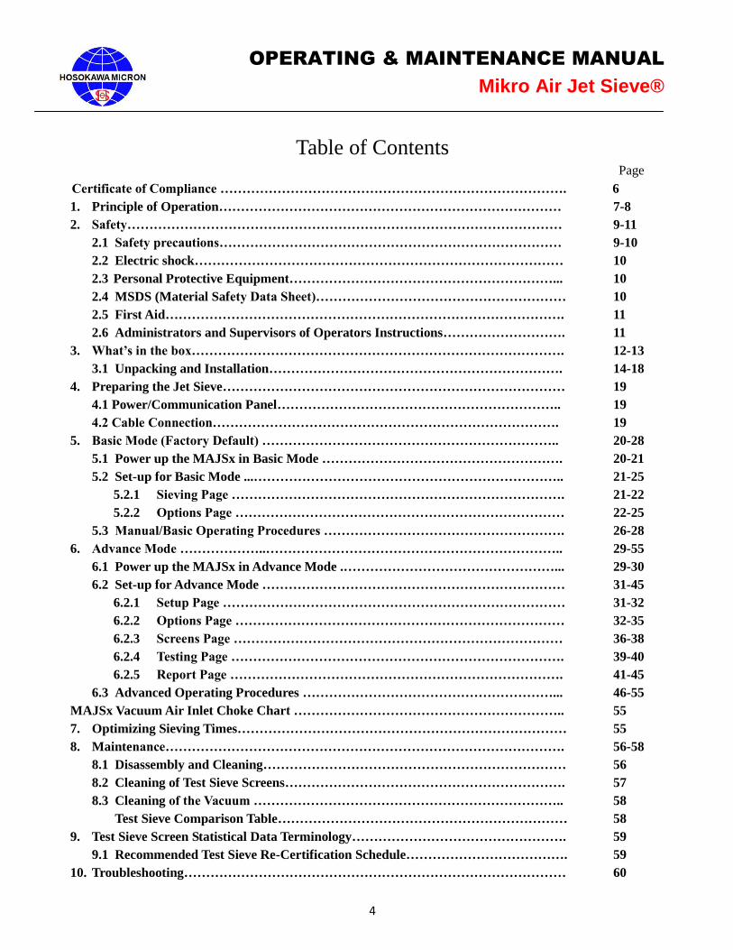
Table of Contents Page
Certificate of Compliance ……………………………………………………………………. 6
1. Principle of Operation…………………………………………………………………… 7-8
2. Safety……………………………………………………………………………………… 9-11
2.1 Safety precautions…………………………………………………………………… 9-10
2.2 Electric shock………………………………………………………………………… 10
2.3 Personal Protective Equipment……………………………………………………... 10
2.4 MSDS (Material Safety Data Sheet)………………………………………………… 10
2.5 First Aid………………………………………………………………………………. 11
2.6 Administrators and Supervisors of Operators Instructions………………………. 11
3. What’s in the box…………………………………………………………………………. 12-13
3.1 Unpacking and Installation…………………………………………………………. 14-18
4. Preparing the Jet Sieve…………………………………………………………………… 19
4.1 Power/Communication Panel……………………………………………………….. 19
4.2 Cable Connection……………………………………………………………………. 19
5. Basic Mode (Factory Default) ………………………………………………………….. 20-28
5.1 Power up the MAJSx in Basic Mode ………………………………………………. 20-21
5.2 Set-up for Basic Mode ...…………………………………………………………….. 21-25
5.2.1 Sieving Page …………………………………………………………………. 21-22
5.2.2 Options Page ………………………………………………………………… 22-25
5.3 Manual/Basic Operating Procedures ………………………………………………. 26-28
6. Advance Mode ………………..………………………………………………………….. 29-55
6.1 Power up the MAJSx in Advance Mode .…………………………………………... 29-30
6.2 Set-up for Advance Mode …………………………………………………………… 31-45
6.2.1 Setup Page …………………………………………………………………… 31-32
6.2.2 Options Page ………………………………………………………………… 32-35
6.2.3 Screens Page ………………………………………………………………… 36-38
6.2.4 Testing Page …………………………………………………………………. 39-40
6.2.5 Report Page …………………………………………………………………. 41-45
6.3 Advanced Operating Procedures …………………………………………………... 46-55
MAJSx Vacuum Air Inlet Choke Chart …………………………………………………….. 55
7. Optimizing Sieving Times………………………………………………………………… 55
8. Maintenance………………………………………………………………………………. 56-58
8.1 Disassembly and Cleaning…………………………………………………………… 56
8.2 Cleaning of Test Sieve Screens………………………………………………………. 57
8.3 Cleaning of the Vacuum …………………………………………………………….. 58
Test Sieve Comparison Table………………………………………………………… 58
9. Test Sieve Screen Statistical Data Terminology…………………………………………. 59
9.1 Recommended Test Sieve Re-Certification Schedule………………………………. 59
10. Troubleshooting…………………………………………………………………………… 60
5
OPERATING & MAINTENANCE MANUAL
Mikro Air Jet Sieve®
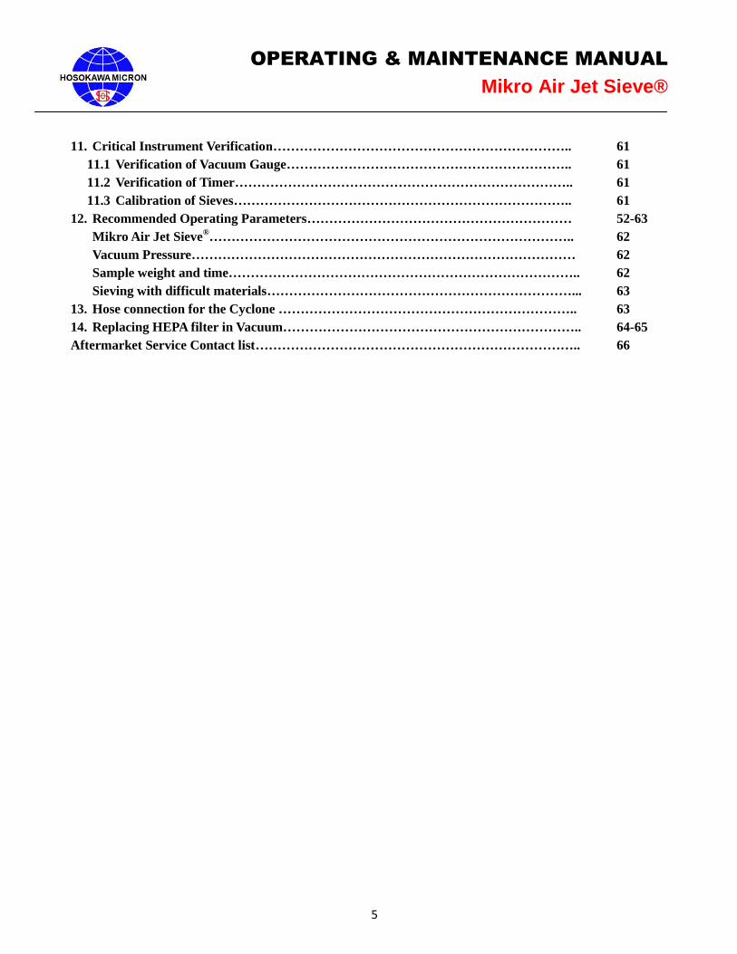
11. Critical Instrument Verification………………………………………………………….. 61
11.1 Verification of Vacuum Gauge……………………………………………………….. 61
11.2 Verification of Timer………………………………………………………………….. 61
11.3 Calibration of Sieves………………………………………………………………….. 61
12. Recommended Operating Parameters…………………………………………………… 52-63
Mikro Air Jet Sieve®……………………………………………………………………….. 62
Vacuum Pressure…………………………………………………………………………… 62
Sample weight and time…………………………………………………………………….. 62
Sieving with difficult materials……………………………………………………………... 63
13. Hose connection for the Cyclone ………………………………………………………….. 63
14. Replacing HEPA filter in Vacuum………………………………………………………….. 64-65
Aftermarket Service Contact list……………………………………………………………….. 66
6
OPERATING & MAINTENANCE MANUAL
Mikro Air Jet Sieve®
CERTIFICATE OF COMPLIANCE
Item: Mikro Air Jet Sieve® Model MAJSx
Electrical Requirements: IEC 61326-1 Edition 2.0 2012-07
Safety Requirements: IEC 61010-1:2001 Edition 2.0
General Requirement: 21CFR210 – Current Good Manufacturing
Processing, Packing or Holding of Drugs
21CFR211 – Current Good Manufacturing Practice for
Finished Pharmaceuticals
NIST National Institute of Standards and Technology
Manufacturer of Record: Hosokawa Micron Powder Systems
10 Chatham Road
Summit, NJ 07901
Contact Information: Hosokawa Micron Powder Systems
10 Chatham Road
Summit, NJ 07901
908-273-6360
Manufacture Date: 09/01/2014
Place of Manufacture: Summit, NJ
Date of Testing: Electrical – 09/08/2014
Safety - 03/19/2015
Place of Testing: Boxborough, MA and Fairfield, NJ
Testing Laboratory: Intertek Testing Services
70 Codman Hill Rd.
Boxborough, MA 01719
Intertek
41 Plymouth St.
Fairfield, NJ 07004

7
OPERATING & MAINTENANCE MANUAL
Mikro Air Jet Sieve®
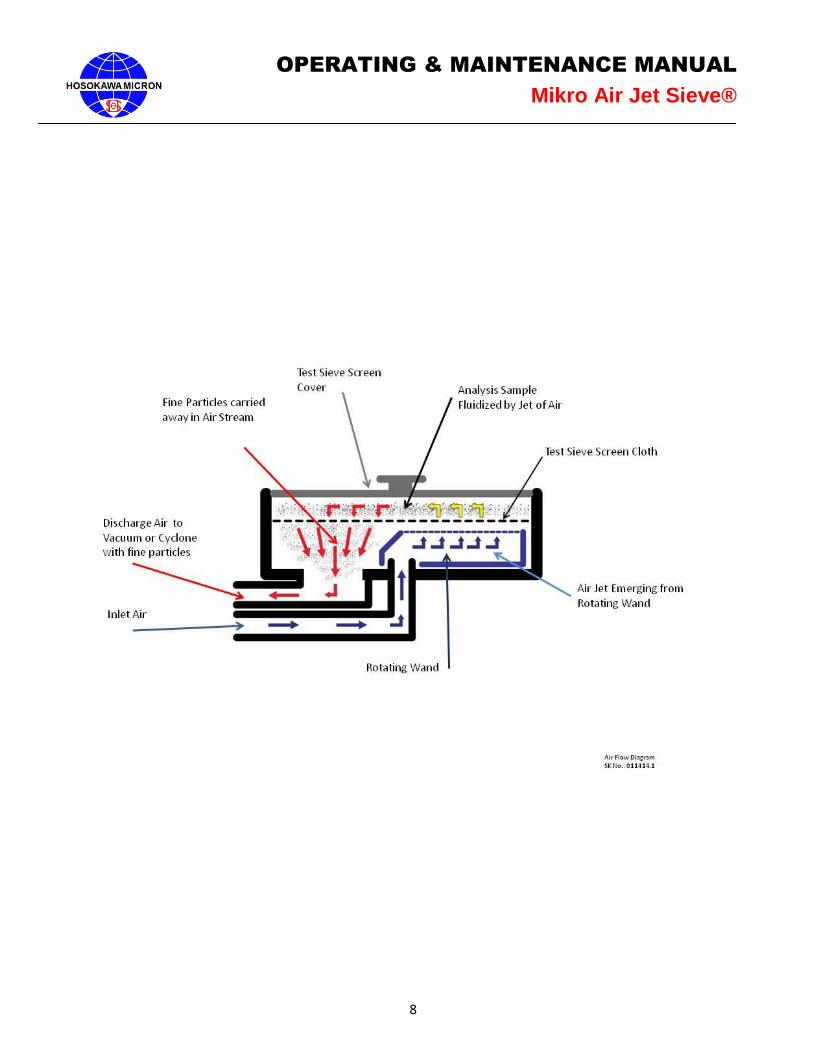
1. Principles of Operation
The Mikro Air Jet Sieve®
- Model x (MAJSx) is a highly accurate and reliable particle size analyzer designed to
determine the particle size distribution of dry powders ranging from 20 to 4,750 micron. Air produced by the
vacuum, jets out of the slotted nozzle that rotates beneath a Test Sieve Screen. The air distributes fine powder in
the area between the Test Sieve Screen cover and the Test Sieve Screen wire cloth, while under negative
pressure. Those particles small enough to pass through the openings of the Test Sieve Screen cloth are carried
in the air stream to either an optionally purchased cyclone or the supplied vacuum for collection. A step-by-
step description of this sieving action of the Mikro Air Jet Sieve® is shown on Air Flow Diagram Sketch No.:
011414.1, on the following page:
Air enters through the Air Inlet opening located on the back of the MAJSx.
Air continues through the duct to the hollow rotation wand.
Air exits the special shaped slot in the top of the rotating wand with sufficient velocity to pass through the
Test Sieve Screen.
The wand is propelled by the electric motor, thereby sweeping the complete diameter of the sieving area.
The jet of air distributes, de-blinds, (dislodges) and possibly de-agglomerates the powder analysis sample
residing on the top surface of the Test Sieve Screen.
Those particles fine enough to pass through the Test Sieve Screen are carried away in the air stream.
Air and fine particles enter the primary discharge duct and exit the MAJSx.
The vacuum pressure is set by the operator on the “Testing” screen (while in the advance mode) or
“Sieving” screen (while in the basic mode) and is automatically adjusted internally by a rotating valve
located between the “Air Inlet” and “Vacuum” air ducts.
In the event the additional vacuum pressure reduction is required, an optionally purchased “Air Slide
Diverter” is available to replace the standard discharge air fitting located on the back of the MAJSx.
The recommended vacuum range, displayed on the “Testing” screen (while in the advance mode) or
“Sieving” screen (while in the basic mode) of the MAJSx during operation, should read between 8 and 16
inches water column. Refer to page 61 for vacuum gauge verification procedures.
Utilizing the standard MAJSx arrangement, the fine dust particles and air exit the main unit and travel
through the vacuum hose to the vacuum collection canister.
If an optional cyclone is attached the dust-laden air is redirected to the cyclone and based upon the
efficiency of the cyclone the coarse particles are collected in the cyclone container and the ultra-fines are
carried in the air stream to the vacuum collection canister.
NOTE:
The MAJSx was design for use with the Hosokawa Micron Test Sieve Screens, while certain
manufactures screens can and do fit the instrument, Hosokawa Micron Powder Systems
cannot guarantee operational results and is not responsible should any damage occur.
When using the Hosokawa Micron Powder Systems 200mm Test Sieve Screens, the Blue Test
Sieve Gasket is NOT required and should be removed from the Test Sieve Screen. The black
O-ring is recommended for proper vacuum seal.
8
OPERATING & MAINTENANCE MANUAL
Mikro Air Jet Sieve®
9
OPERATING & MAINTENANCE MANUAL
Mikro Air Jet Sieve®
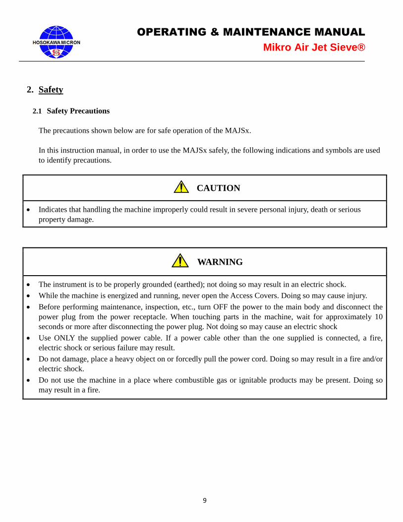
2. Safety
2.1 Safety Precautions
The precautions shown below are for safe operation of the MAJSx.
In this instruction manual, in order to use the MAJSx safely, the following indications and symbols are used
to identify precautions.
CAUTION
Indicates that handling the machine improperly could result in severe personal injury, death or serious
property damage.
WARNING
The instrument is to be properly grounded (earthed); not doing so may result in an electric shock.
While the machine is energized and running, never open the Access Covers. Doing so may cause injury.
Before performing maintenance, inspection, etc., turn OFF the power to the main body and disconnect the
power plug from the power receptacle. When touching parts in the machine, wait for approximately 10
seconds or more after disconnecting the power plug. Not doing so may cause an electric shock
Use ONLY the supplied power cable. If a power cable other than the one supplied is connected, a fire,
electric shock or serious failure may result.
Do not damage, place a heavy object on or forcedly pull the power cord. Doing so may result in a fire and/or
electric shock.
Do not use the machine in a place where combustible gas or ignitable products may be present. Doing so
may result in a fire.
10
OPERATING & MAINTENANCE MANUAL
Mikro Air Jet Sieve®
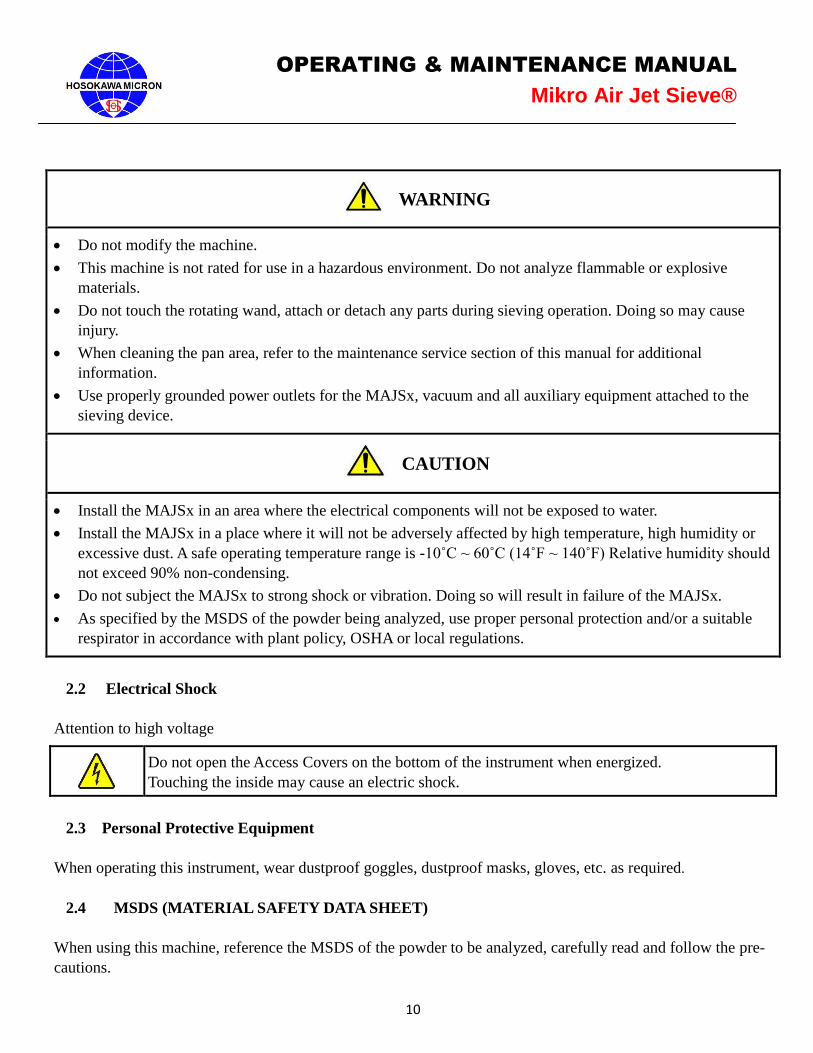
WARNING
Do not modify the machine.
This machine is not rated for use in a hazardous environment. Do not analyze flammable or explosive
materials.
Do not touch the rotating wand, attach or detach any parts during sieving operation. Doing so may cause
injury.
When cleaning the pan area, refer to the maintenance service section of this manual for additional
information.
Use properly grounded power outlets for the MAJSx, vacuum and all auxiliary equipment attached to the
sieving device.
CAUTION
Install the MAJSx in an area where the electrical components will not be exposed to water.
Install the MAJSx in a place where it will not be adversely affected by high temperature, high humidity or
excessive dust. A safe operating temperature range is -10˚C ~ 60˚C (14˚F ~ 140˚F) Relative humidity should
not exceed 90% non-condensing.
Do not subject the MAJSx to strong shock or vibration. Doing so will result in failure of the MAJSx.
As specified by the MSDS of the powder being analyzed, use proper personal protection and/or a suitable
respirator in accordance with plant policy, OSHA or local regulations.
2.2 Electrical Shock
Attention to high voltage
Do not open the Access Covers on the bottom of the instrument when energized.
Touching the inside may cause an electric shock.
2.3 Personal Protective Equipment
When operating this instrument, wear dustproof goggles, dustproof masks, gloves, etc. as required.
2.4 MSDS (MATERIAL SAFETY DATA SHEET)
When using this machine, reference the MSDS of the powder to be analyzed, carefully read and follow the pre-
cautions.
11
OPERATING & MAINTENANCE MANUAL
Mikro Air Jet Sieve®
2.5 First Aid
In the event the powder analyzed comes in contact with the operators’ eyes, skin or is inhaled, administer First
Aid in accordance with the powder MSDS obtained and reviewed prior to starting the analysis.
2.6 Administrators and Supervisors of Operators’ Instructions
Before installing, operating or maintaining this equipment all individuals involved in the installation, operation
and maintenance must carefully read and understand the contents of this manual and follow the Safety
Recommendations.
Notice
To protect the instrument from the effects of static electricity confirm the following:
Make sure that the main Access Cover is attached with all four mounting threaded rubber
pads and that all of the pads are securely tightened and are in good condition.
Use properly grounded power outlets for the MAJSx, vacuum and all auxiliary equipment
attached to the sieving device.
12
OPERATING & MAINTENANCE MANUAL
Mikro Air Jet Sieve®
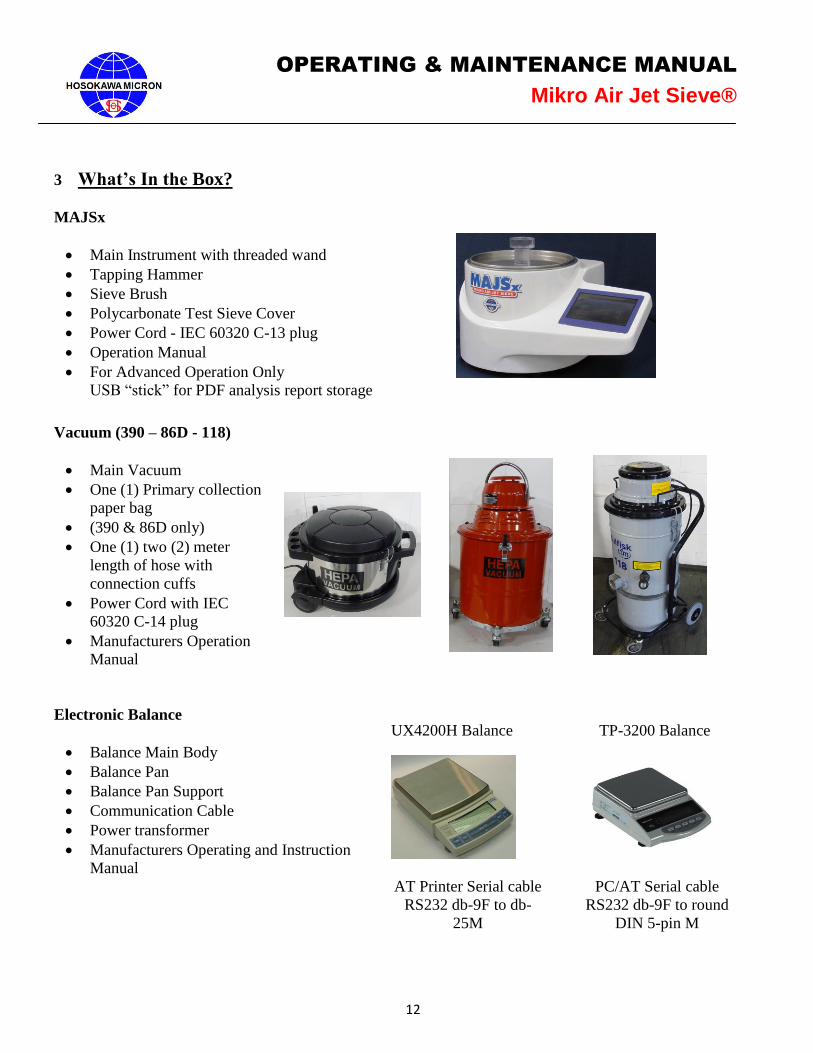
3 What’s In the Box?
MAJSx
Main Instrument with threaded wand
Tapping Hammer
Sieve Brush
Polycarbonate Test Sieve Cover
Power Cord - IEC 60320 C-13 plug
Operation Manual
For Advanced Operation Only
USB “stick” for PDF analysis report storage
Vacuum (390 – 86D - 118)
Main Vacuum
One (1) Primary collection
paper bag
(390 & 86D only)
One (1) two (2) meter
length of hose with
connection cuffs
Power Cord with IEC
60320 C-14 plug
Manufacturers Operation
Manual
Electronic Balance
Balance Main Body
Balance Pan
Balance Pan Support
Communication Cable
Power transformer
Manufacturers Operating and Instruction
Manual
UX4200H Balance TP-3200 Balance
AT Printer Serial cable
RS232 db-9F to db-
25M
PC/AT Serial cable
RS232 db-9F to round
DIN 5-pin M
13
OPERATING & MAINTENANCE MANUAL
Mikro Air Jet Sieve®
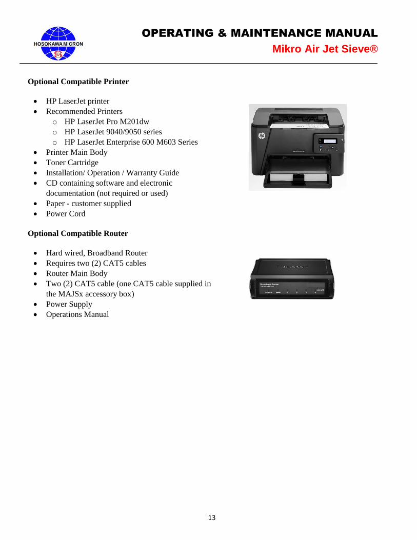
Optional Compatible Printer
HP LaserJet printer
Recommended Printers
o HP LaserJet Pro M201dw
o HP LaserJet 9040/9050 series
o HP LaserJet Enterprise 600 M603 Series
Printer Main Body
Toner Cartridge
Installation/ Operation / Warranty Guide
CD containing software and electronic
documentation (not required or used)
Paper - customer supplied
Power Cord
Optional Compatible Router
Hard wired, Broadband Router
Requires two (2) CAT5 cables
Router Main Body
Two (2) CAT5 cable (one CAT5 cable supplied in
the MAJSx accessory box)
Power Supply
Operations Manual
14
OPERATING & MAINTENANCE MANUAL
Mikro Air Jet Sieve®
3.1 Unpacking and Installation
1. Unpack and remove the MAJSx from the shipping box. Confirm receipt of all the required components
as detailed in the “What’s in the Box” section.
2. Place the accessories (sieve cover, tapping hammer, sieve brush, power cord and, depending upon the
mode, the USB “stick” and CAT5 cable) aside for the moment.
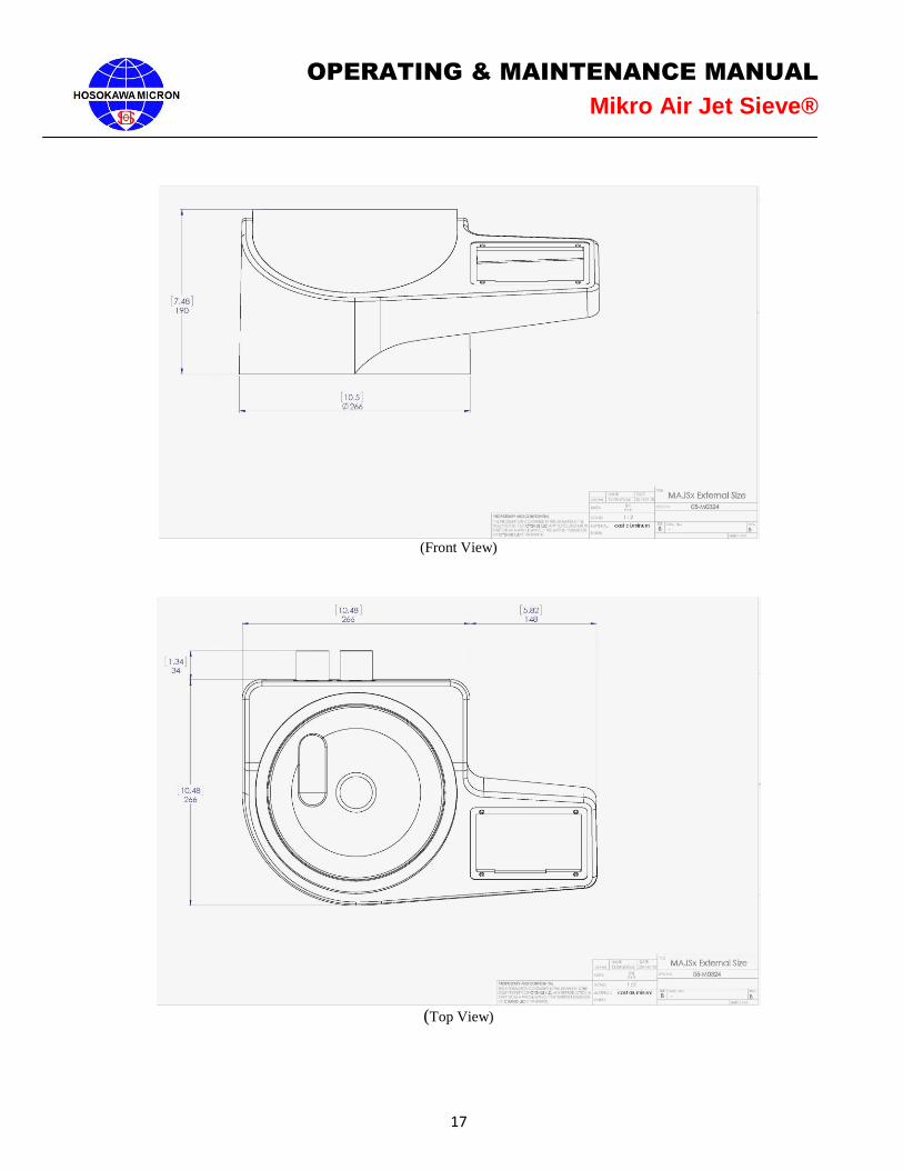
3. Locate the MAJSx on a firm horizontal laboratory bench/table capable of sustaining vibration and
positioned for easy operator access. NOTE: The back of the MAJSx is to be positioned no less than
a minimum of six (6) inches from a wall or a solid obstruction to enable the operator easy access to
the Power switch and the Circuit protector. Refer to General Arrangement Drawing below for
dimensions. The MAJSx weighs approximately 26 Lbs. (11.8 kg). All necessary cautions are to be used
when lifting the instrument.
4. Prior to attaching the power cord to the MAJSx, confirm that a 3-prong 90 to 240 volt, 50/60 hertz
grounded house outlet is within three (3) feet (36" (1 meter)) of the MAJSx. The electrical power outlet
should be “Grounded” (“Earthed”) protected, and rated for a minimum of 15/10 amps at 110/220 volt,
60/50 Hertz.
5. Confirm that the power switch is in the “OFF” position. Insert the power cord into the receptacle
located on the back (labeled “A/C IN”) of the MAJSx. Insert the opposite end of the power cord into the
house power receptacle.
6. MAJSx ADVANCED OPERATION: Insert the USB “stick” into one of the USB ports located on
the back (labeled “USB”) of the MAJSx. The USB “stick” MUST always be in place prior to
powering “ON” the MAJSx. The USB “stick” is required for analysis printing.
7. Open/Unpack the vacuum and confirm receipt of all the required components (Vacuum Main Body, One
(1) Primary collection paper bag, One (1) two (2) meter length of hose with connection cuffs, Power
Cord with IEC 60320 C-14 female plug, and Operation Manual). Additionally, confirm that the filters
are properly installed as detailed in the manufacturer’s instruction manual. Prior to closing the vacuum,
familiarization with the inside of the vacuum, especially the filter mounting, is recommended. Where
ever possible, locate the vacuum, depending upon the vacuum physical size, beneath or alongside of the
lab bench/table. If mounted beneath the lab bench/table to eliminate the hose from being draped over
the top of the bench, drill a 2.5" diameter hole in the bench countertop. This will provide ample
clearance to pass the vacuum hose and power cord through the countertop making for a much cleaner
installation.
8. After locating the vacuum under the bench/table or in another convenient place, plug the vacuum power
cord with the IEC 60320 C-14 connector into the female IEC 60320 C-13 receptacle, (rated for
15A@110 volt / 10A@230 volt) located on the back of the MAJSx. In order to achieve reproducible
analysis results using the MAJSx, the vacuum MUST always be plugged into the MAJSx power outlet
IEC 60320 C-13 receptacle, (rated for 15A@110 volt / 10A@230 volt) located on the back of the
MAJSx. The vacuum’s power switch MUST always be in the “ON” position.
9. Using the supplied vacuum hose, connect the vacuum hose to the outlet hose nipple located on the back
of the MAJSx, labeled “Vacuum Inlet”.
15
OPERATING & MAINTENANCE MANUAL
Mikro Air Jet Sieve®
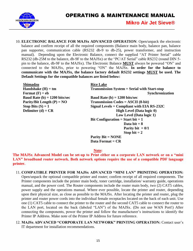
Note:
The MAJSx Advanced Model can be set-up to Print either on a corporate LAN network or on a “mini
LAN” broadband router network. Both network options require the use of a compatible PDF language
printer.
11. COMPATIBLE PRINTER FOR MAJSx ADVANCED “MINI LAN” PRINITING OPERATION:
Open/unpack the optional compatible printer and router; confirm receipt of all required components. The
Printer components include the printer main body, toner cartridge, installation/ warranty guide, operations
manual, and the power cord. The Router components include the router main body, two (2) CAT5 cables,
power supply and the operations manual. Where ever possible, locate the printer and router, depending
upon their physical size, as close as possible to the MAJSx. After locating the printer and router, plug the
printer and router power cords into the individual female receptacles located on the back of each unit. Use
one (1) CAT5 cable to connect the printer to the router and the second CAT5 cable to connect the router to
the LAN port, located on the back (labeled “LAN”) of the MAJSx. (Do not use WAN Port!) After
connecting the components, power the printer and follow the manufacturer’s instructions to identify the
Printer IP Address. Make note of the Printer IP Address for future reference.
12. MAJSx ADVANCED “CORPORATE LAN NETWORK” PRINTING OPERATION: Contact user’s
IT department for installation recommendations.
10. ELECTRONIC BALANCE FOR MAJSx ADVANCED OPERATION: Open/unpack the electronic
balance and confirm receipt of all the required components (Balance main body, balance pan, balance
pan supporter, communication cable (RS232 db-9 to db-25), power transformer, and instruction
manual). Depending upon the Electronic Balance, connect the supplied “AT Printer Serial” cable
RS232 (db-25M to the balance, db-9F to the MAJSx) or the “PC/AT Serial” cable RS232 (round DIN 5-
pin to the balance, db-9F to the MAJSx). The Electronic Balance MUST always be powered “ON” and
connected to the MAJSx, prior to powering “ON” the MAJSx. In order for the balance to
communicate with the MAJSx, the balance factory default RS232 settings MUST be used. The
Default Settings for the compatible balances are listed below:
Shimadzu
Handshake (H) = tm
Format (F) = eb
Baud Rate (b) = 1200 bits/sec
Parity/Bit Length (P) = NO
Stop Bits (S) = 1
Delimiter (d) = CR
Rice Lake
Transmission System = Serial with Start-stop
Synchronization
Baud Rate (b) = 1200 bits/sec
Transmission Codes = ASCII (8-bit)
Signal Levels = Compliant with EIA RS-232C
High Level (Data logic 0)
Low Level (Data logic 1)
Bit Configuration = Start bit = 1
Data bit = 8
Parity bit = 0/1
Stop bit = 2
Parity Bit = NONE
Data Format = CR

16
OPERATING & MAINTENANCE MANUAL
Mikro Air Jet Sieve®
NOTES:
Store the installation, operation and warranty manuals/guides in a safe location for future reference.
In order to achieve reproducible analysis results using the MAJSx, the vacuum MUST always be plugged
into the MAJSx receptacle (outlet) (located on the back of the MAJSx).
The vacuum’s power switch MUST always be in the “ON” position.
The vacuum power outlet located on the back of the MAJSx is rated for a maximum of 15 amps at 230V,
50/60Hz, single phase.
When operating the MAJSx in Basic Mode, the instrument is NOT capable of communicating with a
balance and/or a printer.
When operating the MAJSx in the Advance mode, the Electronic Balance MUST always be powered
“ON” and connected to the MAJSx, prior to powering “ON” the MAJSx.
When operating the MAJSx in the Advance mode, the USB “stick” MUST always be in place prior to
powering “ON” the MAJSx. The USB “stick” is required to access the printing capabilities.
Connect the electrical power cord of the MAJSx and, if operating in the Advance mode, the optional
balance, printer and broadband router to the wall outlet, proper voltage 90 - 240V, 50/60Hz, single phase.
17
OPERATING & MAINTENANCE MANUAL
Mikro Air Jet Sieve®
(Front View)
(Top View)
18
OPERATING & MAINTENANCE MANUAL
Mikro Air Jet Sieve®

19
OPERATING & MAINTENANCE MANUAL
Mikro Air Jet Sieve®
4. Preparing the Air Jet Sieve
4.1 Power/ Communication Panel – Figure 1
1. Power “On/Off” switch
2. Main power “A/C IN” supply 90-240 volt, single phase, 50/60 hertz, current draw without the vacuum
attached is 0.5 amperes at 110 volt.
3. Vacuum Power “VACUUM” supply port, the vacuum MUST always be connected to the
communication “VACUUM” port of the MAJSx.
4. Vacuum receptacle fuse “VACUUM FUSE”
5. MAJSx Advanced Operation Only
a. Three (3) USB ports permitting the connection of USB devices.
b. One (1) RS232 db9M “SCALE” port for the connection of the system
c. Local Area Network “LAN” port (CAT5)for printing and software updates
4.2 Cable Connection
1. Plug the power cord in to the “A/C IN” receptacle located on the back of the MAJSx
2. Connect the Vacuum power cable to the “VACUUM” Receptacle
3. MAJSx Advanced Operation Only a. Connect the Balance communication Cable to the RS232 “SCALE” port
b. Connect the Network cable to the “LAN" port
c. Insert the USB “stick” into one of the USB ports
Figure 1
20
OPERATING & MAINTENANCE MANUAL
Mikro Air Jet Sieve®
5. Basic Mode (Factory Default) - unless ordered as “Advanced Mode”. If ordered as an “Advanced
Mode”, proceed to page 29.
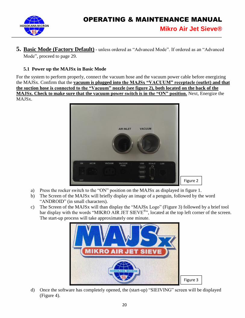
5.1 Power up the MAJSx in Basic Mode
For the system to perform properly, connect the vacuum hose and the vacuum power cable before energizing
the MAJSx. Confirm that the vacuum is plugged into the MAJSx “VACUUM” receptacle (outlet) and that
the suction hose is connected to the “Vacuum” nozzle (see figure 2), both located on the back of the
MAJSx. Check to make sure that the vacuum power switch is in the “ON” position. Next, Energize the
MAJSx.
a) Press the rocker switch to the “ON” position on the MAJSx as displayed in figure 1.
b) The Screen of the MAJSx will briefly display an image of a penguin, followed by the word
“ANDROID” (in small characters).
c) The Screen of the MAJSx will than display the “MAJSx Logo” (Figure 3) followed by a brief tool
bar display with the words “MIKRO AIR JET SIEVE®”, located at the top left corner of the screen.
The start-up process will take approximately one minute.
d) Once the software has completely opened, the (start-up) “SIEIVING” screen will be displayed
(Figure 4).
Figure 3
Figure 2
21
OPERATING & MAINTENANCE MANUAL
Mikro Air Jet Sieve®
5.2 Set-Up for Basic Mode
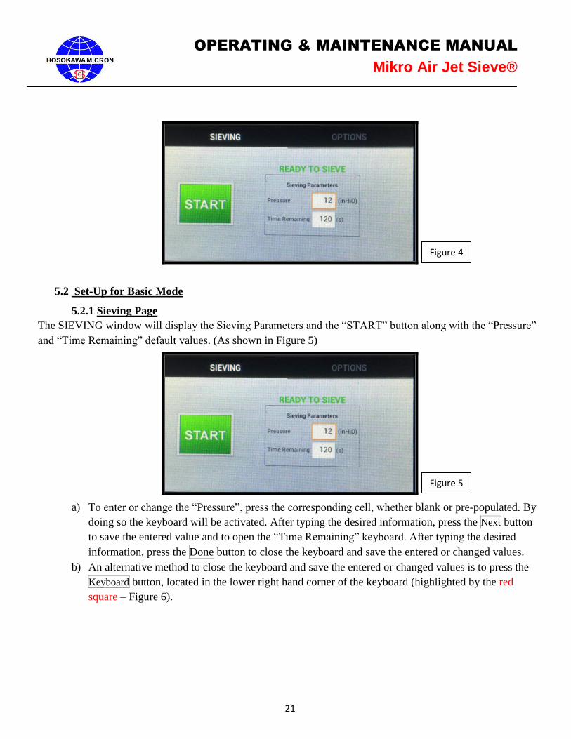
5.2.1 Sieving Page
The SIEVING window will display the Sieving Parameters and the “START” button along with the “Pressure”
and “Time Remaining” default values. (As shown in Figure 5)
a) To enter or change the “Pressure”, press the corresponding cell, whether blank or pre-populated. By
doing so the keyboard will be activated. After typing the desired information, press the Next button
to save the entered value and to open the “Time Remaining” keyboard. After typing the desired
information, press the Done button to close the keyboard and save the entered or changed values.
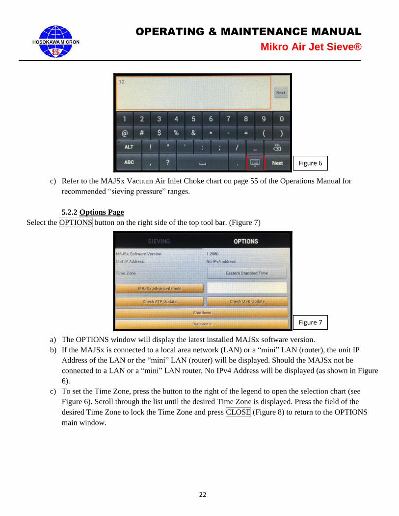
b) An alternative method to close the keyboard and save the entered or changed values is to press the
Keyboard button, located in the lower right hand corner of the keyboard (highlighted by the red
square – Figure 6).
Figure 4
Figure 5
22
OPERATING & MAINTENANCE MANUAL
Mikro Air Jet Sieve®
c) Refer to the MAJSx Vacuum Air Inlet Choke chart on page 55 of the Operations Manual for
recommended “sieving pressure” ranges.
5.2.2 Options Page
Select the OPTIONS button on the right side of the top tool bar. (Figure 7)
a) The OPTIONS window will display the latest installed MAJSx software version.
b) If the MAJSx is connected to a local area network (LAN) or a “mini” LAN (router), the unit IP
Address of the LAN or the “mini” LAN (router) will be displayed. Should the MAJSx not be
connected to a LAN or a “mini” LAN router, No IPv4 Address will be displayed (as shown in Figure
6).
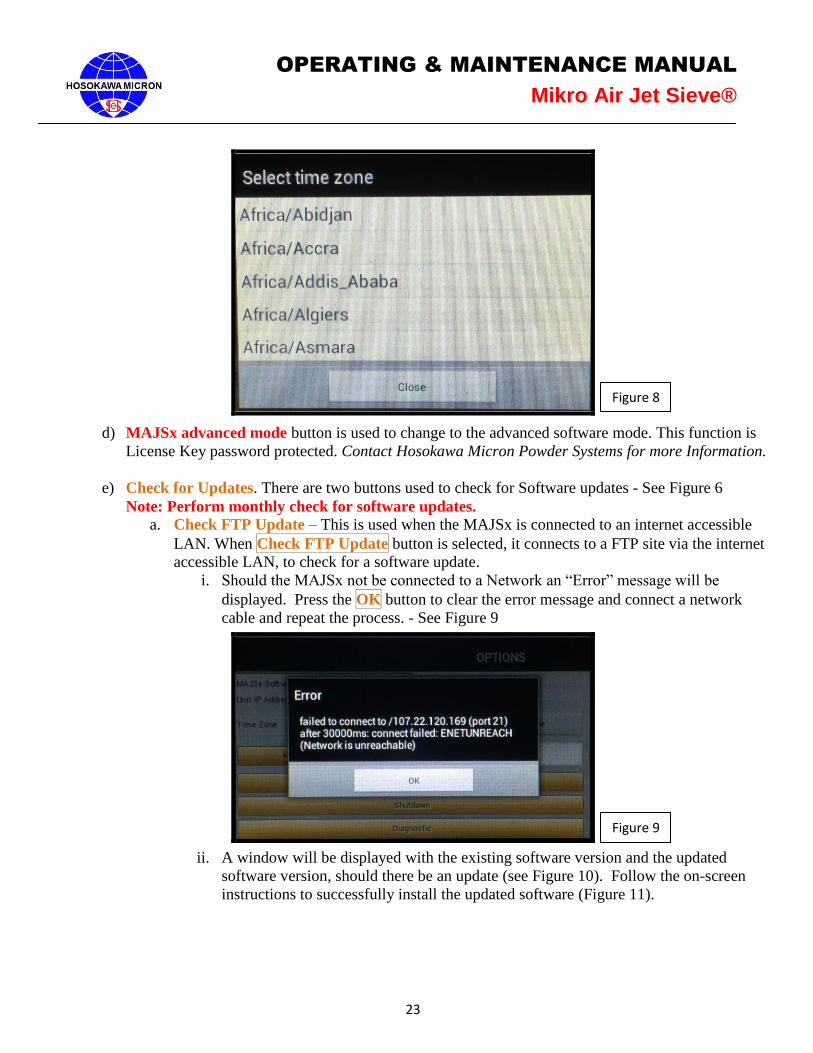
c) To set the Time Zone, press the button to the right of the legend to open the selection chart (see
Figure 6). Scroll through the list until the desired Time Zone is displayed. Press the field of the
desired Time Zone to lock the Time Zone and press CLOSE (Figure 8) to return to the OPTIONS
main window.
Figure 6
Figure 7
23
OPERATING & MAINTENANCE MANUAL
Mikro Air Jet Sieve®
d) MAJSx advanced mode button is used to change to the advanced software mode. This function is
License Key password protected. Contact Hosokawa Micron Powder Systems for more Information.
e) Check for Updates. There are two buttons used to check for Software updates - See Figure 6
Note: Perform monthly check for software updates.
a. Check FTP Update – This is used when the MAJSx is connected to an internet accessible
LAN. When Check FTP Update button is selected, it connects to a FTP site via the internet
accessible LAN, to check for a software update.
i. Should the MAJSx not be connected to a Network an “Error” message will be
displayed. Press the OK button to clear the error message and connect a network
cable and repeat the process. - See Figure 9
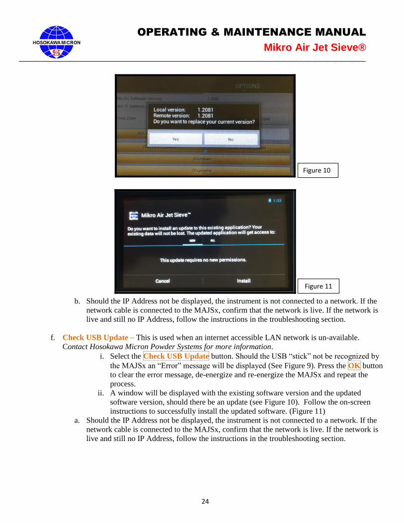
ii. A window will be displayed with the existing software version and the updated
software version, should there be an update (see Figure 10). Follow the on-screen
instructions to successfully install the updated software (Figure 11).
Figure 8
Figure 9
24
OPERATING & MAINTENANCE MANUAL
Mikro Air Jet Sieve®
b. Should the IP Address not be displayed, the instrument is not connected to a network. If the
network cable is connected to the MAJSx, confirm that the network is live. If the network is
live and still no IP Address, follow the instructions in the troubleshooting section.
f. Check USB Update – This is used when an internet accessible LAN network is un-available.
Contact Hosokawa Micron Powder Systems for more information.
i. Select the Check USB Update button. Should the USB “stick” not be recognized by
the MAJSx an “Error” message will be displayed (See Figure 9). Press the OK button
to clear the error message, de-energize and re-energize the MAJSx and repeat the
process.
ii. A window will be displayed with the existing software version and the updated
software version, should there be an update (see Figure 10). Follow the on-screen
instructions to successfully install the updated software. (Figure 11)
a. Should the IP Address not be displayed, the instrument is not connected to a network. If the
network cable is connected to the MAJSx, confirm that the network is live. If the network is
live and still no IP Address, follow the instructions in the troubleshooting section.
Figure 10
Figure 11
25
OPERATING & MAINTENANCE MANUAL
Mikro Air Jet Sieve®
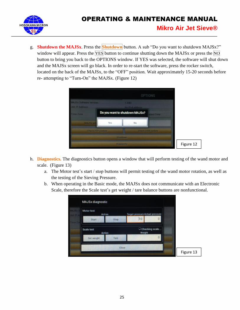
g. Shutdown the MAJSx. Press the Shutdown button. A sub “Do you want to shutdown MAJSx?”
window will appear. Press the YES button to continue shutting down the MAJSx or press the NO
button to bring you back to the OPTIONS window. If YES was selected, the software will shut down
and the MAJSx screen will go black. In order to re-start the software, press the rocker switch,
located on the back of the MAJSx, to the “OFF” position. Wait approximately 15-20 seconds before
re- attempting to “Turn-On” the MAJSx. (Figure 12)
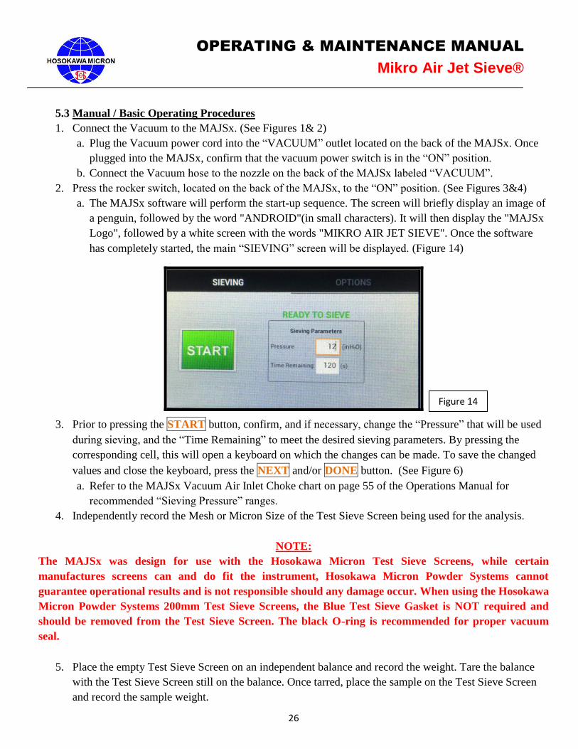
h. Diagnostics. The diagnostics button opens a window that will perform testing of the wand motor and
scale. (Figure 13)
a. The Motor test’s start / stop buttons will permit testing of the wand motor rotation, as well as
the testing of the Sieving Pressure.
b. When operating in the Basic mode, the MAJSx does not communicate with an Electronic
Scale, therefore the Scale test’s get weight / tare balance buttons are nonfunctional.
Figure 12
Figure 13
26
OPERATING & MAINTENANCE MANUAL
Mikro Air Jet Sieve®
5.3 Manual / Basic Operating Procedures
1. Connect the Vacuum to the MAJSx. (See Figures 1& 2)
a. Plug the Vacuum power cord into the “VACUUM” outlet located on the back of the MAJSx. Once
plugged into the MAJSx, confirm that the vacuum power switch is in the “ON” position.
b. Connect the Vacuum hose to the nozzle on the back of the MAJSx labeled “VACUUM”.
2. Press the rocker switch, located on the back of the MAJSx, to the “ON” position. (See Figures 3&4)
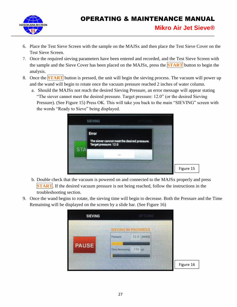
a. The MAJSx software will perform the start-up sequence. The screen will briefly display an image of
a penguin, followed by the word "ANDROID"(in small characters). It will then display the "MAJSx
Logo", followed by a white screen with the words "MIKRO AIR JET SIEVE". Once the software
has completely started, the main “SIEVING” screen will be displayed. (Figure 14)
3. Prior to pressing the START button, confirm, and if necessary, change the “Pressure” that will be used
during sieving, and the “Time Remaining” to meet the desired sieving parameters. By pressing the
corresponding cell, this will open a keyboard on which the changes can be made. To save the changed
values and close the keyboard, press the NEXT and/or DONE button. (See Figure 6)
a. Refer to the MAJSx Vacuum Air Inlet Choke chart on page 55 of the Operations Manual for
recommended “Sieving Pressure” ranges.
4. Independently record the Mesh or Micron Size of the Test Sieve Screen being used for the analysis.
NOTE:
The MAJSx was design for use with the Hosokawa Micron Test Sieve Screens, while certain
manufactures screens can and do fit the instrument, Hosokawa Micron Powder Systems cannot
guarantee operational results and is not responsible should any damage occur. When using the Hosokawa
Micron Powder Systems 200mm Test Sieve Screens, the Blue Test Sieve Gasket is NOT required and
should be removed from the Test Sieve Screen. The black O-ring is recommended for proper vacuum
seal.
5. Place the empty Test Sieve Screen on an independent balance and record the weight. Tare the balance
with the Test Sieve Screen still on the balance. Once tarred, place the sample on the Test Sieve Screen
and record the sample weight.
Figure 14
27
OPERATING & MAINTENANCE MANUAL
Mikro Air Jet Sieve®
6. Place the Test Sieve Screen with the sample on the MAJSx and then place the Test Sieve Cover on the
Test Sieve Screen.
7. Once the required sieving parameters have been entered and recorded, and the Test Sieve Screen with
the sample and the Sieve Cover has been placed on the MAJSx, press the START button to begin the
analysis.
8. Once the START button is pressed, the unit will begin the sieving process. The vacuum will power up
and the wand will begin to rotate once the vacuum pressure reached 2 inches of water column.
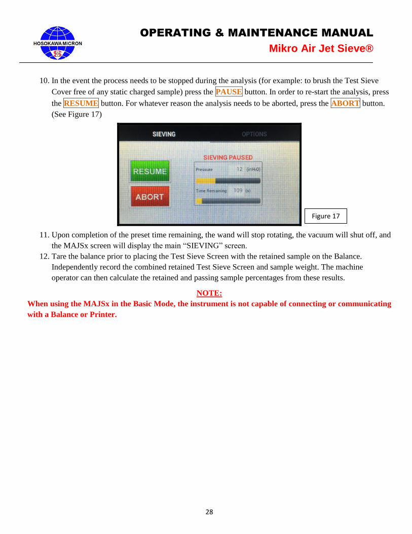
a. Should the MAJSx not reach the desired Sieving Pressure, an error message will appear stating
“The siever cannot meet the desired pressure. Target pressure: 12.0” (or the desired Sieving
Pressure). (See Figure 15) Press OK. This will take you back to the main “SIEVING” screen with
the words “Ready to Sieve” being displayed.
b. Double check that the vacuum is powered on and connected to the MAJSx properly and press
START. If the desired vacuum pressure is not being reached, follow the instructions in the
troubleshooting section.
9. Once the wand begins to rotate, the sieving time will begin to decrease. Both the Pressure and the Time
Remaining will be displayed on the screen by a slide bar. (See Figure 16)
Figure 15
Figure 16
28
OPERATING & MAINTENANCE MANUAL
Mikro Air Jet Sieve®
10. In the event the process needs to be stopped during the analysis (for example: to brush the Test Sieve
Cover free of any static charged sample) press the PAUSE button. In order to re-start the analysis, press
the RESUME button. For whatever reason the analysis needs to be aborted, press the ABORT button.
(See Figure 17)
11. Upon completion of the preset time remaining, the wand will stop rotating, the vacuum will shut off, and
the MAJSx screen will display the main “SIEVING” screen.
12. Tare the balance prior to placing the Test Sieve Screen with the retained sample on the Balance.
Independently record the combined retained Test Sieve Screen and sample weight. The machine
operator can then calculate the retained and passing sample percentages from these results.
NOTE:
When using the MAJSx in the Basic Mode, the instrument is not capable of connecting or communicating
with a Balance or Printer.
Figure 17

29
OPERATING & MAINTENANCE MANUAL
Mikro Air Jet Sieve®
6. Advanced Mode
6.1 Power Up the MAJSx in Advanced Mode
For the system to perform properly, the components are to be energized in the following order: First, Confirm
that the vacuum is plugged into the MAJSx “VACUUM” receptacle (outlet) and that the suction hose is
connected to the “Vacuum “nozzle, both located on the back of the MAJSx. (See Figures 1&2) Check to
make sure that the vacuum power switch is in the “ON” position.
Second, power up the Balance. This will prevent any communication conflict between the Balance and the
MAJSx.
Insert the USB “stick” into one of the USB ports located on the back (labeled “USB”) of the MAJSx. (See
Figure 1) The USB “stick” must always be in place prior to powering “ON” the MAJSx. The USB “stick” is
required for analysis printing. (Maximum 4GB capacity each GB can save 52,400 analysis reports)
Confirm that the Printer and either a corporate LAN network or a “mini LAN” broadband router
network is powered on and connected to the MAJSx, prior to energizing the MAJSx.
If a Keyboard and mouse are used, plug into the USB ports located on the back (labeled “USB”) of the
MAJSx.
a. To energize (wake-up) the balance press the Power Button.
b. Press the rocker switch to the “ON” position on the MAJSx as shown above.
c. The Screen of the MAJSx will briefly display an image of a penguin, followed by the word
“ANDROID” (in small characters).
d. The Screen of the MAJSx will than display the “MAJSx Logo” (see Figure 3) followed by a brief
tool bar display with the words “MIKRO AIR JET SIEVE®”, located at the top left corner of the
screen. The start-up process will take approximately one minute.
e. Once the Software has completely started the following screens will be displayed (Figure 18 & 19).
In order to advance press the OK button.
Figure 18
30
OPERATING & MAINTENANCE MANUAL
Mikro Air Jet Sieve®
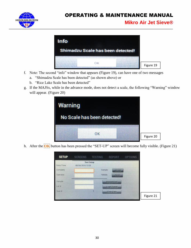
f. Note: The second “info” window that appears (Figure 19), can have one of two messages
a. “Shimadzu Scale has been detected” (as shown above) or
b. “Rice Lake Scale has been detected”
g. If the MAJSx, while in the advance mode, does not detect a scale, the following “Warning” window
will appear. (Figure 20)
h. After the OK button has been pressed the “SET-UP” screen will become fully visible. (Figure 21)
Figure 19
Figure 20
Figure 21

31
OPERATING & MAINTENANCE MANUAL
Mikro Air Jet Sieve®
6.2 Set-Up for Advance Mode
6.2.1 Setup Page – See Figure 21
Should this be the first time the instrument is being used, the input cells will be blank. If the instrument has
been used prior, the cells will be populated with data from the last analysis session. To continue, the Repeat
Test, Load Preset or the Clear Data button MUST be pressed.
a) By pressing Repeat Test the operator can use or change the operator input fields, the Test Sieve
Screen selection and/or the Sieving Time and Sieving Pressure that was used on the prior test.
b) By pressing Load Preset the operator will be able to select a prior analysis from those stored within
the “on-board” computer. Once the preset test is selected, the operator must select Repeat Test to
perform the analysis using the preselected operator input fields, Test Sieve Screen(s), Sieving Time
and desired sieving Pressure for each Test Sieve Screen.
c) By pressing Clear Data all operator input fields will be erased and the test number will index to the
next number. In order to perform an analysis the “Company”, “Operator”, “Sample” and “Lot
Number” fields must be filled prior to attempting to perform the next analysis; otherwise you
will receive an error message. NOTE: NO BLANK SPACES OR PUNCTUATION MARKS
may be used when completing the operator input fields. Should the any of the operator fields
consist of blank spaces; the MAJSx will NOT print the analysis report, however, underscores
(“_”) will be accepted should it be necessary to separate words.
d) The Test Number, Date and Time fields are populated by the computer automatically and can NOT
be changed by the operator.
e) In order to enter or change data in a specific operator field, press the corresponding cell, whether
blank or pre-populated. By doing so the keyboard will be activated. After typing the desired
information, press the Done button to save the entered values. Use the same procedure for the
remaining operator input fields.
a. An alternative method to close the keyboard and save the entered or changed values is to
press the Keyboard button, located in the lower right hand corner of the keyboard (highlighted
by the red square – Figure 22).
32
OPERATING & MAINTENANCE MANUAL
Mikro Air Jet Sieve®
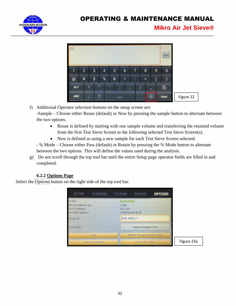
f) Additional Operator selection buttons on the setup screen are:
-Sample – Choose either Reuse (default) or New by pressing the sample button to alternate between
the two options.
Reuse is defined by starting with one sample volume and transferring the retained volume
from the first Test Sieve Screen to the following selected Test Sieve Screen(s).
New is defined as using a new sample for each Test Sieve Screen selected.
- % Mode – Choose either Pass (default) or Retain by pressing the % Mode button to alternate
between the two options. This will define the values used during the analysis.
g) Do not scroll through the top tool bar until the entire Setup page operator fields are filled in and
completed.
6.2.2 Options Page
Select the Options button on the right side of the top tool bar.
Figure 22
Figure 23a
33
OPERATING & MAINTENANCE MANUAL
Mikro Air Jet Sieve®
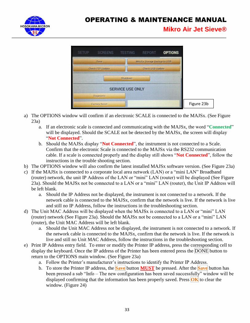
a) The OPTIONS window will confirm if an electronic SCALE is connected to the MAJSx. (See Figure
23a)
a. If an electronic scale is connected and communicating with the MAJSx, the word “Connected”
will be displayed. Should the SCALE not be detected by the MAJSx, the screen will display
“Not Connected”.
b. Should the MAJSx display “Not Connected”, the instrument is not connected to a Scale.
Confirm that the electronic Scale is connected to the MAJSx via the RS232 communication
cable. If a scale is connected properly and the display still shows “Not Connected”, follow the
instructions in the trouble shooting section.
b) The OPTIONS window will also confirm the latest installed MAJSx software version. (See Figure 23a)
c) If the MAJSx is connected to a corporate local area network (LAN) or a “mini LAN” Broadband
(router) network, the unit IP Address of the LAN or “mini” LAN (router) will be displayed (See Figure
23a). Should the MAJSx not be connected to a LAN or a “mini” LAN (router), the Unit IP Address will
be left blank.
a. Should the IP Address not be displayed, the instrument is not connected to a network. If the
network cable is connected to the MAJSx, confirm that the network is live. If the network is live
and still no IP Address, follow the instructions in the troubleshooting section.
d) The Unit MAC Address will be displayed when the MAJSx is connected to a LAN or “mini” LAN
(router) network (See Figure 23a). Should the MAJSx not be connected to a LAN or a “mini” LAN
(router), the Unit MAC Address will be left blank.
a. Should the Unit MAC Address not be displayed, the instrument is not connected to a network. If
the network cable is connected to the MAJSx, confirm that the network is live. If the network is
live and still no Unit MAC Address, follow the instructions in the troubleshooting section.
e) Print IP Address entry field. To enter or modify the Printer IP address, press the corresponding cell to
display the keyboard. Once the IP address of the Printer has been entered press the DONE button to
return to the OPTIONS main window. (See Figure 23a)
a. Follow the Printer’s manufacturer’s instructions to identify the Printer IP Address.
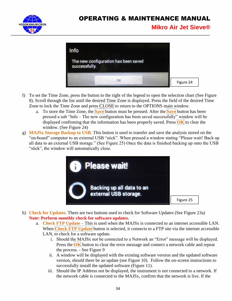
b. To store the Printer IP address, the Save button MUST be pressed. After the Save button has
been pressed a sub “Info – The new configuration has been saved successfully” window will be
displayed confirming that the information has been properly saved. Press OK to clear the
window. (Figure 24)
Figure 23b
34
OPERATING & MAINTENANCE MANUAL
Mikro Air Jet Sieve®
f) To set the Time Zone, press the button to the right of the legend to open the selection chart (See Figure
8). Scroll through the list until the desired Time Zone is displayed. Press the field of the desired Time
Zone to lock the Time Zone and press CLOSE to return to the OPTIONS main window.
a. To store the Time Zone, the Save button must be pressed. After the Save button has been
pressed a sub “Info – The new configuration has been saved successfully” window will be
displayed confirming that the information has been properly saved. Press OK to clear the
window. (See Figure 24)
g) MAJSx Storage Backup to USB. This button is used to transfer and save the analysis stored on the
“on-board” computer to an external USB “stick”. When pressed a window stating “Please wait! Back up
all data to an external USB storage.” (See Figure 25) Once the data is finished backing up onto the USB
“stick”, the window will automatically close.
h) Check for Updates. There are two buttons used to check for Software Updates (See Figure 23a)
Note: Perform monthly check for software updates.
a. Check FTP Update – This is used when the MAJSx is connected to an internet accessible LAN.
When Check FTP Update button is selected, it connects to a FTP site via the internet accessible
LAN, to check for a software update.
i. Should the MAJSx not be connected to a Network an “Error” message will be displayed.
Press the OK button to clear the error message and connect a network cable and repeat
the process. - See Figure 9
ii. A window will be displayed with the existing software version and the updated software
version, should there be an update (see Figure 10). Follow the on-screen instructions to
successfully install the updated software (Figure 11).
iii. Should the IP Address not be displayed, the instrument is not connected to a network. If
the network cable is connected to the MAJSx, confirm that the network is live. If the
Figure 24
Figure 25
35
OPERATING & MAINTENANCE MANUAL
Mikro Air Jet Sieve®
network is live and still no IP Address, follow the instructions in the troubleshooting
section.
b. Check USB Update – This is used when an internet accessible LAN network is un-available.
Contact Hosokawa Micron Powder Systems for more information.
i. Select the Check USB Update button. Should the USB “stick” not be recognized by the
MAJSx an “Error” message will be displayed (See Figure 9). Press the OK button to
clear the error message, de-energize, confirm that the USB stick is properly seated and
then re-energize the MAJSx and repeat the process.
ii. A window will be displayed with the existing software version and the updated software
version, should there be an update (see Figure 10). Follow the on-screen instructions to
successfully install the updated software. (Figure 11)
i) Shutdown the MAJSx. Press the Shutdown button. A sub “Do you want to shutdown MAJSx?”
window will appear. Press the YES button to continue shutting down the MAJSx or press the NO button
to bring you back to the OPTIONS window. If YES was selected, the software will shut down and the
MAJSx screen will go black. In order to re-start the software, press the rocker switch, located on the
back of the MAJSx, to the “OFF” position. Wait approximately 15-20 seconds before re- attempting to
“Turn-On” the MAJSx. (Figure 12)
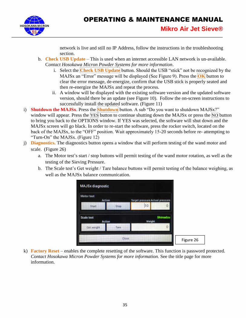
j) Diagnostics. The diagnostics button opens a window that will perform testing of the wand motor and
scale. (Figure 26)
a. The Motor test’s start / stop buttons will permit testing of the wand motor rotation, as well as the
testing of the Sieving Pressure.
b. The Scale test’s Get weight / Tare balance buttons will permit testing of the balance weighing, as
well as the MAJSx balance communication.
k) Factory Reset – enables the complete resetting of the software. This function is password protected.
Contact Hosokawa Micron Powder Systems for more information. See the title page for more
information.
Figure 26
36
OPERATING & MAINTENANCE MANUAL
Mikro Air Jet Sieve®
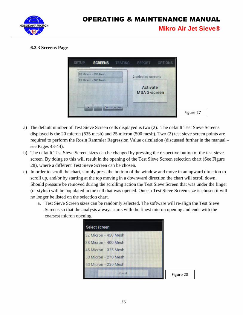
6.2.3 Screens Page
a) The default number of Test Sieve Screen cells displayed is two (2). The default Test Sieve Screens
displayed is the 20 micron (635 mesh) and 25 micron (500 mesh). Two (2) test sieve screen points are
required to perform the Rosin Rammler Regression Value calculation (discussed further in the manual –
see Pages 43-44).
b) The default Test Sieve Screen sizes can be changed by pressing the respective button of the test sieve
screen. By doing so this will result in the opening of the Test Sieve Screen selection chart (See Figure
28), where a different Test Sieve Screen can be chosen.
c) In order to scroll the chart, simply press the bottom of the window and move in an upward direction to
scroll up, and/or by starting at the top moving in a downward direction the chart will scroll down.
Should pressure be removed during the scrolling action the Test Sieve Screen that was under the finger
(or stylus) will be populated in the cell that was opened. Once a Test Sieve Screen size is chosen it will
no longer be listed on the selection chart.
a. Test Sieve Screen sizes can be randomly selected. The software will re-align the Test Sieve
Screens so that the analysis always starts with the finest micron opening and ends with the
coarsest micron opening.
Figure 27
Figure 28
37
OPERATING & MAINTENANCE MANUAL
Mikro Air Jet Sieve®
d) To add/remove a Test Sieve Screen from the analysis menu, press the “-” button to remove the bottom
Test Sieve Screen shown on the list and/or “+” to add another Test Sieve Screen to the analysis menu.
This action will open the Test Sieve Screen selection chart, as shown in Figure 28.
a. To Change a Test Sieve Screen, highlight the Test Sieve Screen to be changed. This will open
the Test Sieve Screen selection chart. From here, select the desired Test Sieve Screen.
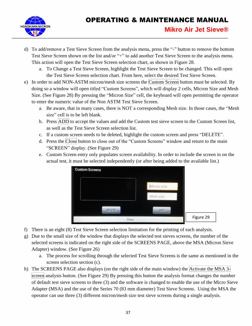
e) In order to add NON-ASTM micron/mesh size screens the Custom Screen button must be selected. By
doing so a window will open titled “Custom Screens”, which will display 2 cells, Micron Size and Mesh
Size. (See Figure 28) By pressing the “Micron Size” cell, the keyboard will open permitting the operator
to enter the numeric value of the Non ASTM Test Sieve Screen.
a. Be aware, that in many cases, there is NOT a corresponding Mesh size. In those cases, the “Mesh
size” cell is to be left blank.
b. Press ADD to accept the values and add the Custom test sieve screen to the Custom Screen list,
as well as the Test Sieve Screen selection list.
c. If a custom screen needs to be deleted, highlight the custom screen and press “DELETE”.
d. Press the Close button to close out of the “Custom Screens” window and return to the main
“SCREEN” display. (See Figure 29)
e. Custom Screen entry only populates screen availability. In order to include the screen in on the
actual test, it must be selected independently (or after being added to the available list.)
f) There is an eight (8) Test Sieve Screen selection limitation for the printing of each analysis.
g) Due to the small size of the window that displays the selected test sieves screens, the number of the
selected screens is indicated on the right side of the SCREENS PAGE, above the MSA (Micron Sieve
Adapter) window. (See Figure 26)
a. The process for scrolling through the selected Test Sieve Screens is the same as mentioned in the
screen selection section (c).
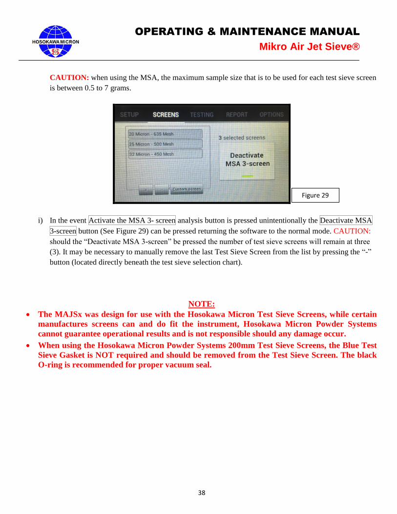
h) The SCREENS PAGE also displays (on the right side of the main window) the Activate the MSA 3-
screen analysis button. (See Figure 29) By pressing this button the analysis format changes the number
of default test sieve screens to three (3) and the software is changed to enable the use of the Micro Sieve
Adapter (MSA) and the use of the Series 70 (83 mm diameter) Test Sieve Screens. Using the MSA the
operator can use three (3) different micron/mesh size test sieve screens during a single analysis.
Figure 29
38
OPERATING & MAINTENANCE MANUAL
Mikro Air Jet Sieve®
CAUTION: when using the MSA, the maximum sample size that is to be used for each test sieve screen
is between 0.5 to 7 grams.
i) In the event Activate the MSA 3- screen analysis button is pressed unintentionally the Deactivate MSA
3-screen button (See Figure 29) can be pressed returning the software to the normal mode. CAUTION:
should the “Deactivate MSA 3-screen” be pressed the number of test sieve screens will remain at three
(3). It may be necessary to manually remove the last Test Sieve Screen from the list by pressing the “-”
button (located directly beneath the test sieve selection chart).
NOTE:
The MAJSx was design for use with the Hosokawa Micron Test Sieve Screens, while certain
manufactures screens can and do fit the instrument, Hosokawa Micron Powder Systems
cannot guarantee operational results and is not responsible should any damage occur.
When using the Hosokawa Micron Powder Systems 200mm Test Sieve Screens, the Blue Test
Sieve Gasket is NOT required and should be removed from the Test Sieve Screen. The black
O-ring is recommended for proper vacuum seal.
Figure 29
39
OPERATING & MAINTENANCE MANUAL
Mikro Air Jet Sieve®
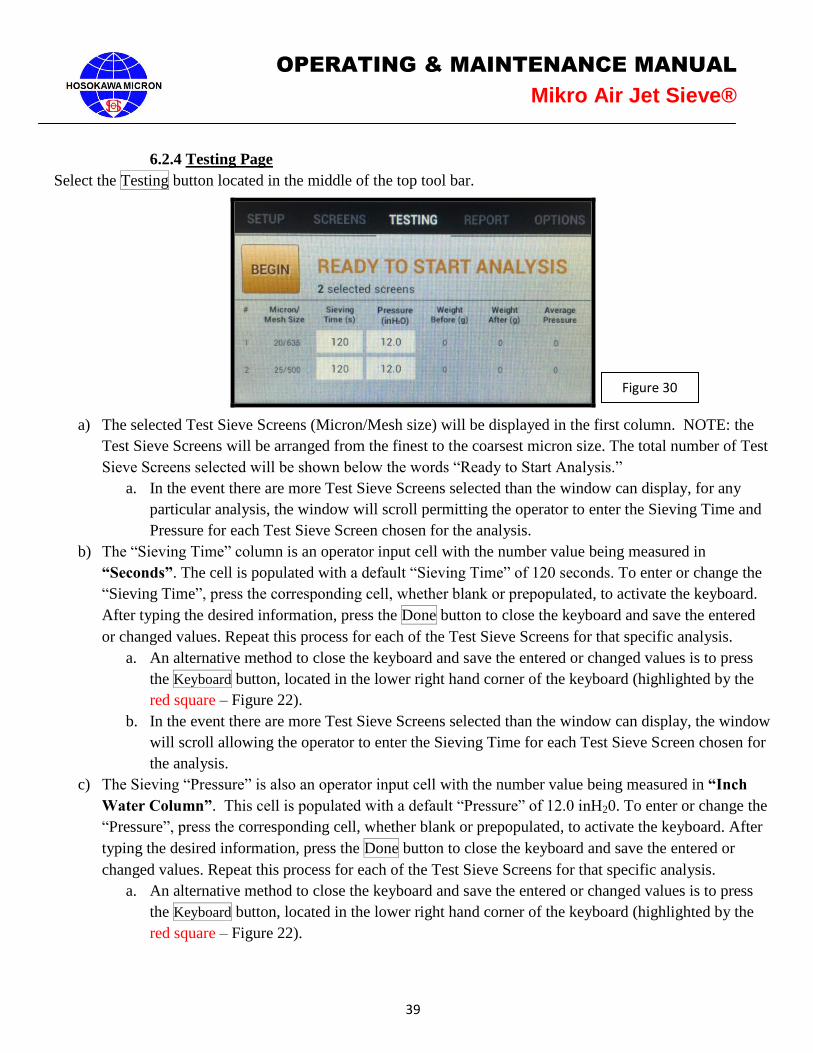
6.2.4 Testing Page
Select the Testing button located in the middle of the top tool bar.
a) The selected Test Sieve Screens (Micron/Mesh size) will be displayed in the first column. NOTE: the
Test Sieve Screens will be arranged from the finest to the coarsest micron size. The total number of Test
Sieve Screens selected will be shown below the words “Ready to Start Analysis.”
a. In the event there are more Test Sieve Screens selected than the window can display, for any
particular analysis, the window will scroll permitting the operator to enter the Sieving Time and
Pressure for each Test Sieve Screen chosen for the analysis.
b) The “Sieving Time” column is an operator input cell with the number value being measured in
“Seconds”. The cell is populated with a default “Sieving Time” of 120 seconds. To enter or change the
“Sieving Time”, press the corresponding cell, whether blank or prepopulated, to activate the keyboard.
After typing the desired information, press the Done button to close the keyboard and save the entered
or changed values. Repeat this process for each of the Test Sieve Screens for that specific analysis.
a. An alternative method to close the keyboard and save the entered or changed values is to press
the Keyboard button, located in the lower right hand corner of the keyboard (highlighted by the
red square – Figure 22).
b. In the event there are more Test Sieve Screens selected than the window can display, the window
will scroll allowing the operator to enter the Sieving Time for each Test Sieve Screen chosen for
the analysis.
c) The Sieving “Pressure” is also an operator input cell with the number value being measured in “Inch
Water Column”. This cell is populated with a default “Pressure” of 12.0 inH20. To enter or change the
“Pressure”, press the corresponding cell, whether blank or prepopulated, to activate the keyboard. After
typing the desired information, press the Done button to close the keyboard and save the entered or
changed values. Repeat this process for each of the Test Sieve Screens for that specific analysis.
a. An alternative method to close the keyboard and save the entered or changed values is to press
the Keyboard button, located in the lower right hand corner of the keyboard (highlighted by the
red square – Figure 22).
Figure 30
40
OPERATING & MAINTENANCE MANUAL
Mikro Air Jet Sieve®
b. In the event there are more Test Sieve Screens selected than the window can display, the window
will scroll allowing the operator to enter the Pressure for each Test Sieve Screen chosen for the
analysis.
c. The operator may vary the Sieving “Pressure” from Test Sieve Screen to Test Sieve Screen
depending upon the material and/or sieve opening. For example a friable material may require a
lower sieving “pressure”, while agglomerative material may require a higher pressure.
d. Refer to the MAJSx Vacuum Air Inlet Choke chart on page 55 of the Operations Manual for
recommended “Sieving Pressure” ranges.
d) Once the values for the Sieving Time and the Vacuum Pressure have been entered press the Begin
button to start the process and follow the on-screen instructions.
NOTE:
The MAJSx was design for use with the Hosokawa Micron Test Sieve Screens, while certain
manufactures screens can and do fit the instrument, Hosokawa Micron Powder Systems
cannot guarantee operational results and is not responsible should any damage occur.
When using the Hosokawa Micron Powder Systems 200mm Test Sieve Screens, the Blue Test
Sieve Gasket is NOT required and should be removed from the Test Sieve Screen. The black
O-ring is recommended for proper vacuum seal.
41
OPERATING & MAINTENANCE MANUAL
Mikro Air Jet Sieve®
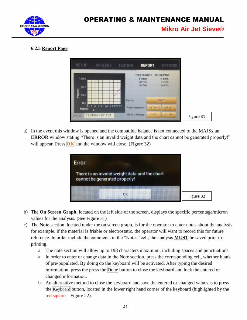
6.2.5 Report Page
a) In the event this window is opened and the compatible balance is not connected to the MAJSx an
ERROR window stating “There is an invalid weight data and the chart cannot be generated properly!”
will appear. Press OK and the window will close. (Figure 32)
b) The On Screen Graph, located on the left side of the screen, displays the specific percentage/micron
values for the analysis. (See Figure 31)
c) The Note section, located under the on screen graph, is for the operator to enter notes about the analysis,
for example, if the material is friable or electrostatic, the operator will want to record this for future
reference. In order include the comments in the “Notes” cell; the analysis MUST be saved prior to
printing.
a. The note section will allow up to 198 characters maximum, including spaces and punctuations.
a. In order to enter or change data in the Note section, press the corresponding cell, whether blank
of pre-populated. By doing do the keyboard will be activated. After typing the desired
information, press the press the Done button to close the keyboard and lock the entered or
changed information.
b. An alternative method to close the keyboard and save the entered or changed values is to press
the Keyboard button, located in the lower right hand corner of the keyboard (highlighted by the
red square – Figure 22).
Figure 31
Figure 32
42
OPERATING & MAINTENANCE MANUAL
Mikro Air Jet Sieve®
d) The TEST RESULTS displays the “Sample” (reuse or new) used and the “% Mode” (pass or retained)
calculated during the analysis. (See section 6.2, Setup page, page 32, section (g) for further definition of
the “Sample” and the “% Mode”) The test results also display the respective Test Sieve Screen(s) and
the % Cum. (cumulative) values for the analysis. Note: This is a small window and scrolling may be
required to view the entire list of Test Sieve Screens.
e) The Graph Type Print Selection has two options.
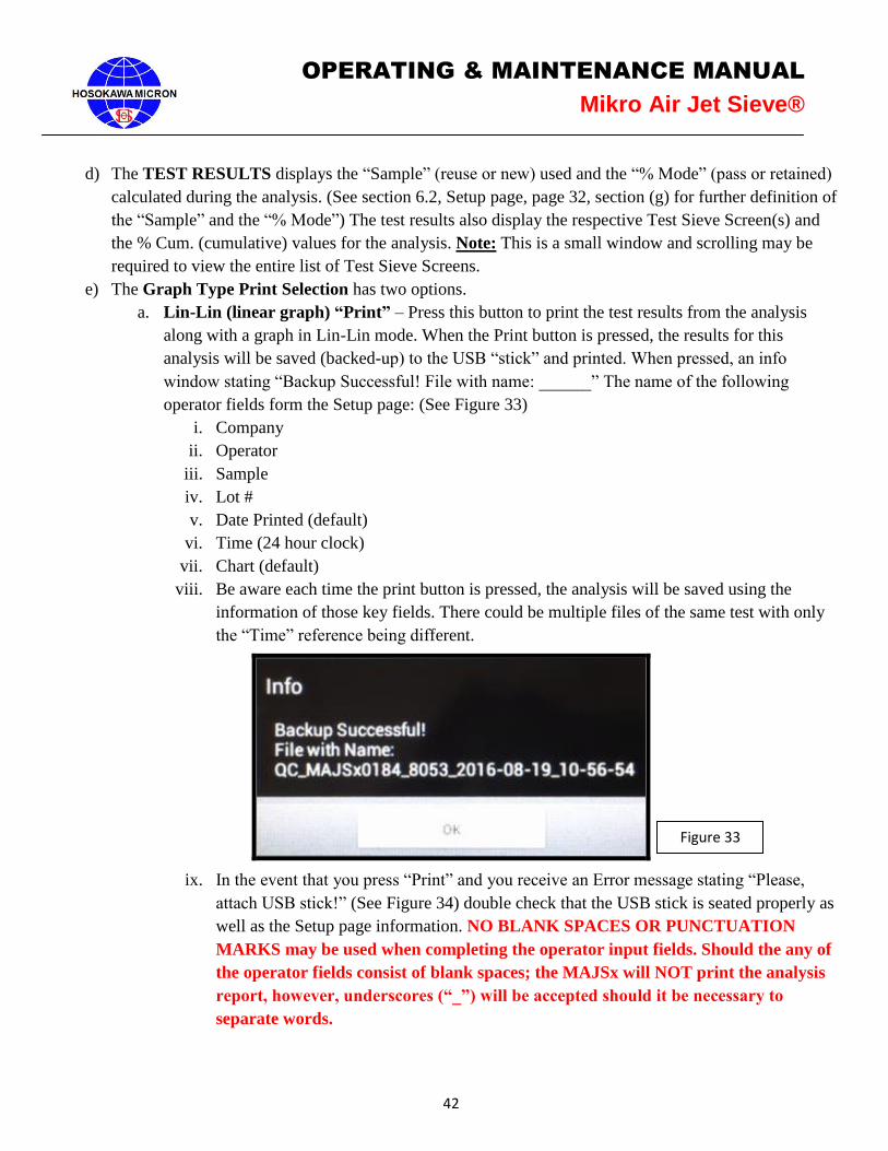
a. Lin-Lin (linear graph) “Print” – Press this button to print the test results from the analysis
along with a graph in Lin-Lin mode. When the Print button is pressed, the results for this
analysis will be saved (backed-up) to the USB “stick” and printed. When pressed, an info
window stating “Backup Successful! File with name: ______” The name of the following
operator fields form the Setup page: (See Figure 33)
i. Company
ii. Operator
iii. Sample
iv. Lot #
v. Date Printed (default)
vi. Time (24 hour clock)
vii. Chart (default)
viii. Be aware each time the print button is pressed, the analysis will be saved using the
information of those key fields. There could be multiple files of the same test with only
the “Time” reference being different.
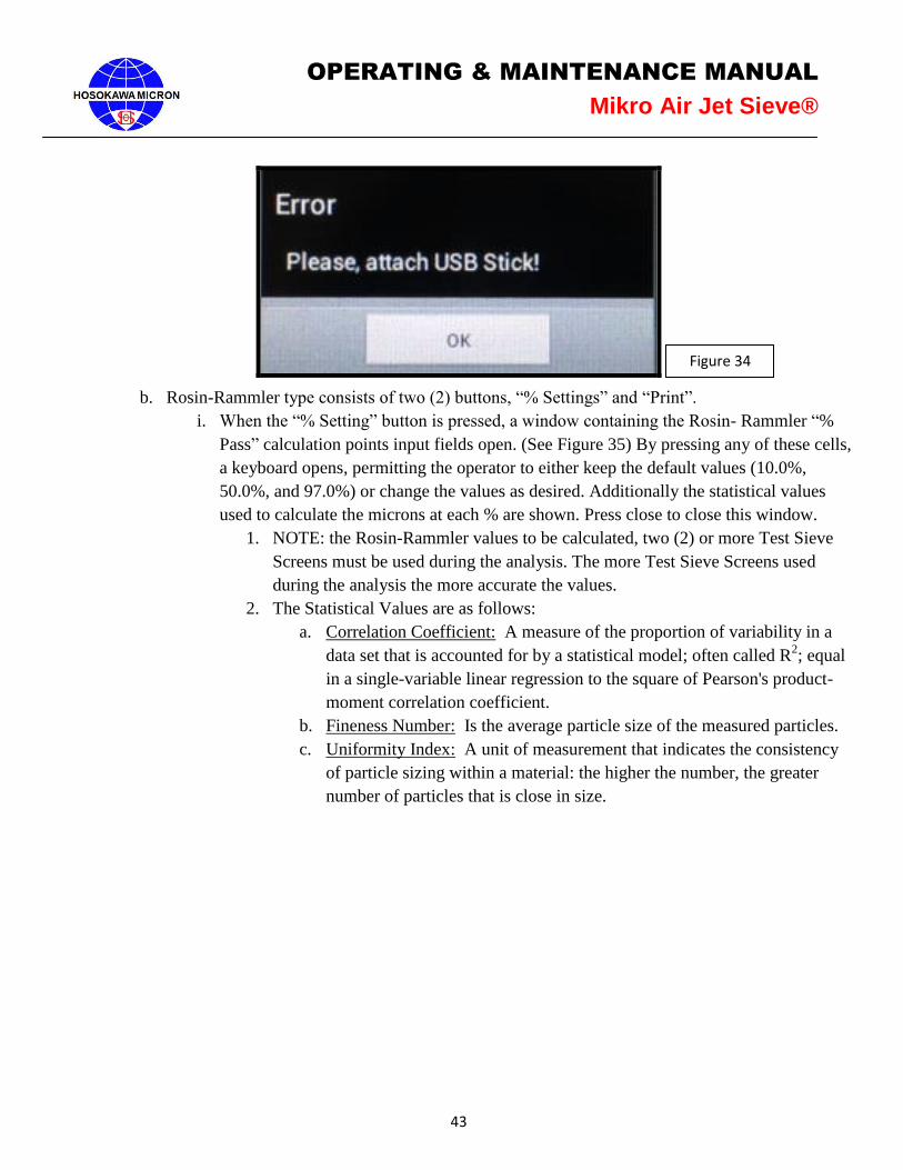
ix. In the event that you press “Print” and you receive an Error message stating “Please,
attach USB stick!” (See Figure 34) double check that the USB stick is seated properly as
well as the Setup page information. NO BLANK SPACES OR PUNCTUATION
MARKS may be used when completing the operator input fields. Should the any of
the operator fields consist of blank spaces; the MAJSx will NOT print the analysis
report, however, underscores (“_”) will be accepted should it be necessary to
separate words.
Figure 33
43
OPERATING & MAINTENANCE MANUAL
Mikro Air Jet Sieve®
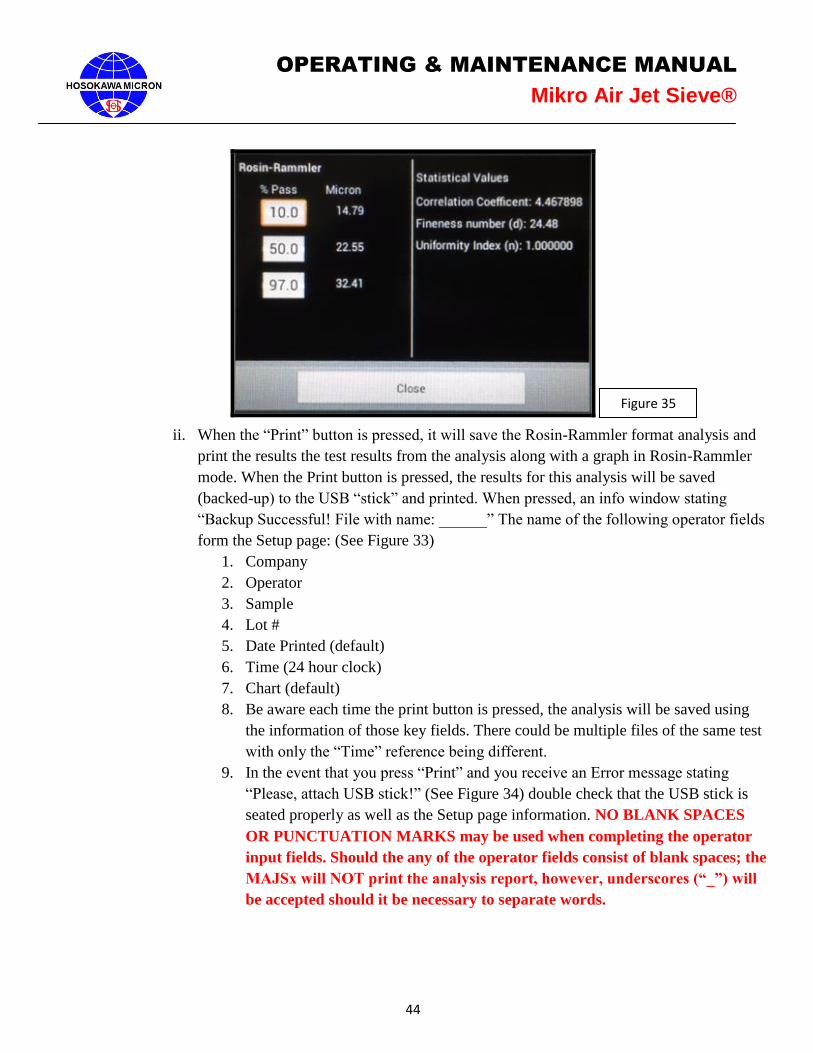
b. Rosin-Rammler type consists of two (2) buttons, “% Settings” and “Print”.
i. When the “% Setting” button is pressed, a window containing the Rosin- Rammler “%
Pass” calculation points input fields open. (See Figure 35) By pressing any of these cells,
a keyboard opens, permitting the operator to either keep the default values (10.0%,
50.0%, and 97.0%) or change the values as desired. Additionally the statistical values
used to calculate the microns at each % are shown. Press close to close this window.
1. NOTE: the Rosin-Rammler values to be calculated, two (2) or more Test Sieve
Screens must be used during the analysis. The more Test Sieve Screens used
during the analysis the more accurate the values.
2. The Statistical Values are as follows:
a. Correlation Coefficient: A measure of the proportion of variability in a
data set that is accounted for by a statistical model; often called R2; equal
in a single-variable linear regression to the square of Pearson's product-
moment correlation coefficient.
b. Fineness Number: Is the average particle size of the measured particles.
c. Uniformity Index: A unit of measurement that indicates the consistency
of particle sizing within a material: the higher the number, the greater
number of particles that is close in size.
Figure 34
44
OPERATING & MAINTENANCE MANUAL
Mikro Air Jet Sieve®
ii. When the “Print” button is pressed, it will save the Rosin-Rammler format analysis and
print the results the test results from the analysis along with a graph in Rosin-Rammler
mode. When the Print button is pressed, the results for this analysis will be saved
(backed-up) to the USB “stick” and printed. When pressed, an info window stating
“Backup Successful! File with name: ______” The name of the following operator fields
form the Setup page: (See Figure 33)
1. Company
2. Operator
3. Sample
4. Lot #
5. Date Printed (default)
6. Time (24 hour clock)
7. Chart (default)
8. Be aware each time the print button is pressed, the analysis will be saved using
the information of those key fields. There could be multiple files of the same test
with only the “Time” reference being different.
9. In the event that you press “Print” and you receive an Error message stating
“Please, attach USB stick!” (See Figure 34) double check that the USB stick is
seated properly as well as the Setup page information. NO BLANK SPACES
OR PUNCTUATION MARKS may be used when completing the operator
input fields. Should the any of the operator fields consist of blank spaces; the
MAJSx will NOT print the analysis report, however, underscores (“_”) will
be accepted should it be necessary to separate words.
Figure 35
45
OPERATING & MAINTENANCE MANUAL
Mikro Air Jet Sieve®
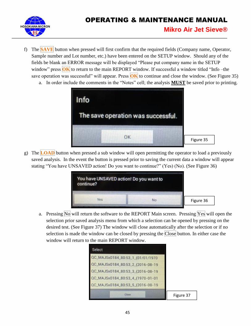
f) The SAVE button when pressed will first confirm that the required fields (Company name, Operator,
Sample number and Lot number, etc.) have been entered on the SETUP window. Should any of the
fields be blank an ERROR message will be displayed “Please put company name in the SETUP
window” press OK to return to the main REPORT window. If successful a window titled “Info –the
save operation was successful” will appear. Press OK to continue and close the window. (See Figure 35)
a. In order include the comments in the “Notes” cell; the analysis MUST be saved prior to printing.
g) The LOAD button when pressed a sub window will open permitting the operator to load a previously
saved analysis. In the event the button is pressed prior to saving the current data a window will appear
stating “You have UNSAVED action! Do you want to continue?” (Yes) (No). (See Figure 36)
a. Pressing No will return the software to the REPORT Main screen. Pressing Yes will open the
selection prior saved analysis menu from which a selection can be opened by pressing on the
desired test. (See Figure 37) The window will close automatically after the selection or if no
selection is made the window can be closed by pressing the Close button. In either case the
window will return to the main REPORT window.
Figure 35
Figure 36
Figure 37
46
OPERATING & MAINTENANCE MANUAL
Mikro Air Jet Sieve®
6.3 Advanced Operating Procedures
1. Confirm the MAJSx and accessories have been up-packed, set-up and installed properly. Once
installation has been confirmed, energize all accessories. (See sections 3.1, 4.1 and 4.2).
a. Confirm that the MAJSx OPTIONS page is displaying the Unit IP Address, Unit MAC Address
and that the Printer’s IP Address has been entered and saved in the corresponding cell. (See
section 6.2 OPTIONS PAGE)
2. Once the above is confirmed, power on the MAJSx.
a. Press the rocker switch, located on the back of the MAJSx, to the “ON” position. (See Figure 1).
Allow the software to start-up and stabilize until the info windows stating “Last Test session has
been restored” and “Shimadzu Scale (or Rice Lake Scale) has been detected” is displayed.
i. If the MAJSx does not detect a scale, a “Warning” window stating “No Scale has been
detected!” will be displayed. (Please see section 6.2.2)
b. Press the OK button to close the “Info Windows” and display the “SETUP” page.
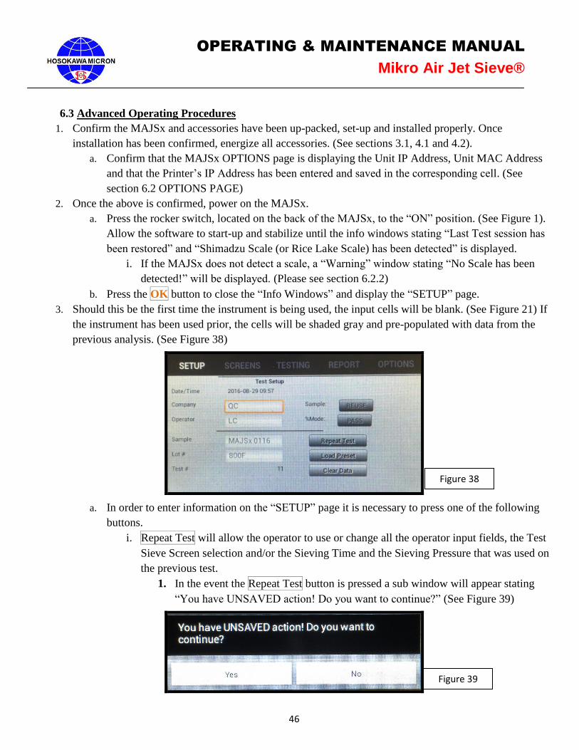
3. Should this be the first time the instrument is being used, the input cells will be blank. (See Figure 21) If
the instrument has been used prior, the cells will be shaded gray and pre-populated with data from the
previous analysis. (See Figure 38)
a. In order to enter information on the “SETUP” page it is necessary to press one of the following
buttons.
i. Repeat Test will allow the operator to use or change all the operator input fields, the Test
Sieve Screen selection and/or the Sieving Time and the Sieving Pressure that was used on
the previous test.
1. In the event the Repeat Test button is pressed a sub window will appear stating
“You have UNSAVED action! Do you want to continue?” (See Figure 39)
Figure 38
Figure 39
47
OPERATING & MAINTENANCE MANUAL
Mikro Air Jet Sieve®
a. If Yes is pressed, the software will clear the gray shading from the
operator fields, displaying the previous analysis information while
indexing to the next test number in the sequence.
b. If NO is pressed, the sub window will close displaying the “SETUP”
screen with the gray shading through the operator input fields.
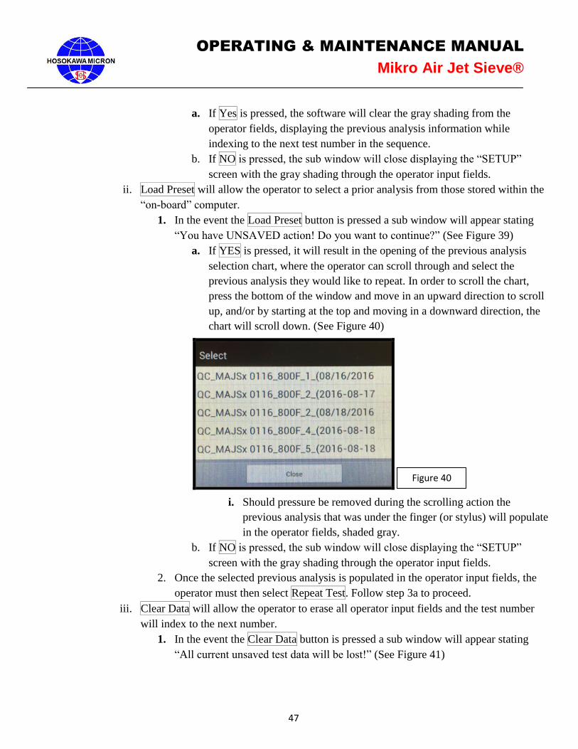
ii. Load Preset will allow the operator to select a prior analysis from those stored within the
“on-board” computer.
1. In the event the Load Preset button is pressed a sub window will appear stating
“You have UNSAVED action! Do you want to continue?” (See Figure 39)
a. If YES is pressed, it will result in the opening of the previous analysis
selection chart, where the operator can scroll through and select the
previous analysis they would like to repeat. In order to scroll the chart,
press the bottom of the window and move in an upward direction to scroll
up, and/or by starting at the top and moving in a downward direction, the
chart will scroll down. (See Figure 40)
i. Should pressure be removed during the scrolling action the
previous analysis that was under the finger (or stylus) will populate
in the operator fields, shaded gray.
b. If NO is pressed, the sub window will close displaying the “SETUP”
screen with the gray shading through the operator input fields.
2. Once the selected previous analysis is populated in the operator input fields, the
operator must then select Repeat Test. Follow step 3a to proceed.
iii. Clear Data will allow the operator to erase all operator input fields and the test number
will index to the next number.
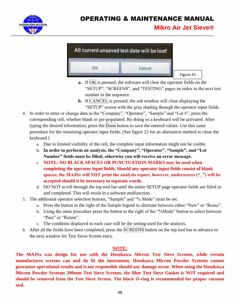
1. In the event the Clear Data button is pressed a sub window will appear stating
“All current unsaved test data will be lost!” (See Figure 41)
Figure 40
48
OPERATING & MAINTENANCE MANUAL
Mikro Air Jet Sieve®
a. If OK is pressed, the software will clear the operator fields on the
“SETUP”, “SCREENS”, and “TESTING” pages an index to the next test
number in the sequence.
b. If CANCEL is pressed, the sub window will close displaying the
“SETUP” screen with the gray shading through the operator input fields.
4. In order to enter or change data in the “Company”, “Operator”, “Sample” and “Lot #”, press the
corresponding cell, whether blank or pre-populated. By doing so a keyboard will be activated. After
typing the desired information, press the Done button to save the entered values. Use this same
procedure for the remaining operator input fields. (See figure 22 for an alternative method to close the
keyboard.)
a. Due to limited visibility of the cell, the complete input information might not be visible.
b. In order to perform an analysis, the “Company”, “Operator”, “Sample”, and “Lot
Number” fields must be filled; otherwise you will receive an error message.
c. NOTE: NO BLACK SPACES OR PUNCTUATION MARKS may be used when
completing the operator input fields. Should any operator input fields consist of blank
spaces; the MAJSx will NOT print the analysis report, however, underscores (“_”) will be
accepted should it be necessary to separate words.
d. DO NOT scroll through the top tool bar until the entire SETUP page operator fields are filled in
and completed. This will result in a software malfunction.
5. The additional operator selection buttons, “Sample” and “% Mode” must be set.
a. Press the button to the right of the Sample legend to alternate between either “New” or “Reuse”.
b. Using the same procedure press the button to the right of the “%Mode” button to select between
“Pass” or “Retain”.
c. The condition displayed in each case will be the setting used for the analysis.
6. After all the fields have been completed, press the SCREENS button on the top tool bar to advance to
the next window for Test Sieve Screen entry.
NOTE:
The MAJSx was design for use with the Hosokawa Micron Test Sieve Screens, while certain
manufactures screens can and do fit the instrument, Hosokawa Micron Powder Systems cannot
guarantee operational results and is not responsible should any damage occur. When using the Hosokawa
Micron Powder Systems 200mm Test Sieve Screens, the Blue Test Sieve Gasket is NOT required and
should be removed from the Test Sieve Screen. The black O-ring is recommended for proper vacuum
seal.
Figure 41

49
OPERATING & MAINTENANCE MANUAL
Mikro Air Jet Sieve®
7. As mentioned earlier in the manual, the default number of Test Sieve Screens is two (2). The default
sizes are 20 micron (635 mesh) and 25 micron (500 mesh). (See Figure 27)
a. Two (2) test sieve screen points are required to perform the Rosin Rammler Regression Value
calculation (See pages 43-44).
8. The default Test Sieve Screen sizes can be changed by pressing the respective button of the test sieve
screen. By doing so this will result in the opening of the Test Sieve Screen selection chart (See Figure
28), where a different Test Sieve Screen can be chosen.
9. In order to scroll the chart, simply press the bottom of the window and move in an upward direction to
scroll up, and/or by starting at the top moving in a downward direction the chart will scroll down.
Should pressure be removed during the scrolling action the Test Sieve Screen that was under the finger
(or stylus) will be populated in the cell that was opened. To select a Test Sieve Screen, simply press the
corresponding cell. The corresponding cell will turn orange, and replace the last test sieve screen in the
list.
a. Once a Test Sieve Screen size is chosen it will no longer be listed on the selection chart.
i. Test Sieve Screen sizes can be randomly selected. The software will re-align the Test
Sieve Screens so that the analysis always starts with the finest micron opening and ends
with the coarsest micron opening.
10. To add/remove a Test Sieve Screen from the analysis menu, press the “-” button to remove the bottom
Test Sieve Screen shown on the list and/or “+” to add another Test Sieve Screen to the analysis menu.
This action will open the Test Sieve Screen selection chart, as shown in Figure 28.
a. To Change a Test Sieve Screen, highlight the Test Sieve Screen to be changed. This will open
the Test Sieve Screen selection chart. From here, select the desired Test Sieve Screen.
b. In order to add NON-ASTM micron/mesh size screens the Custom Screen button must be
selected. Follow the Custom Screen
11. There is an eight (8) Test Sieve Screen selection limitation for the printing of each analysis.
12. Due to the small size of the window that displays the selected test sieves screens, the number of the
selected screens is indicated on the right side of the SCREENS PAGE, above the MSA (Micron Sieve
Adapter) window. (See Figure 27)
13. Upon completion of the Test Sieve Screen selection press the TESTING button located on the top tool
bar.
14. Prior to pressing the BEGIN button, confirm and, if necessary, change the “Sieving Time” and the
“Pressure” for each Test Sieve Screen selected. These cells will be populated with a default “Sieving
Time” of 120 seconds and a default “Pressure” of 12.0 inch H20. (See Figure 30) To change the default
setting, press the corresponding cell to activate the keyboard. This will open the keyboard permitting the
numeric changes to take place. Remember to press “Done” to save each changed value.
a. Refer to the MAJSx Vacuum Air Inlet Choke chart on page 55 of the Operations Manual for
recommended “Sieving Pressure” ranges.
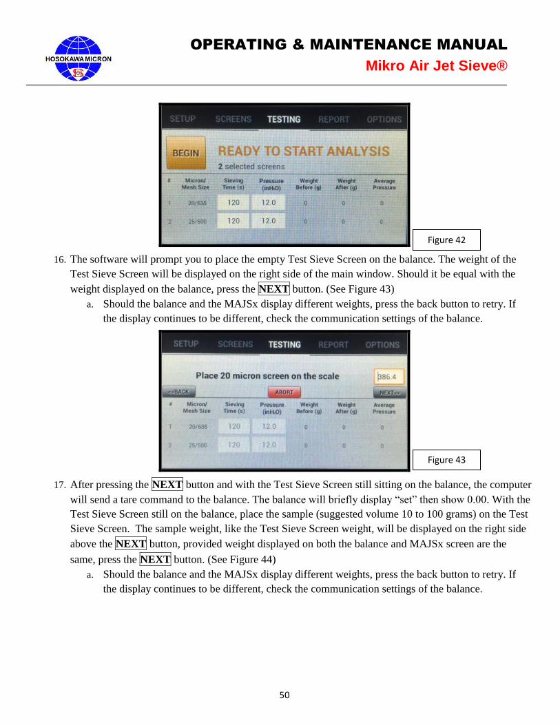
15. Once the required values have been entered press the BEGIN button to start the analysis. (See Figure
42) Follow the on screen instruction to proceed through the analysis process.
50
OPERATING & MAINTENANCE MANUAL
Mikro Air Jet Sieve®
16. The software will prompt you to place the empty Test Sieve Screen on the balance. The weight of the
Test Sieve Screen will be displayed on the right side of the main window. Should it be equal with the
weight displayed on the balance, press the NEXT button. (See Figure 43)
a. Should the balance and the MAJSx display different weights, press the back button to retry. If
the display continues to be different, check the communication settings of the balance.
17. After pressing the NEXT button and with the Test Sieve Screen still sitting on the balance, the computer
will send a tare command to the balance. The balance will briefly display “set” then show 0.00. With the
Test Sieve Screen still on the balance, place the sample (suggested volume 10 to 100 grams) on the Test
Sieve Screen. The sample weight, like the Test Sieve Screen weight, will be displayed on the right side
above the NEXT button, provided weight displayed on both the balance and MAJSx screen are the
same, press the NEXT button. (See Figure 44)
a. Should the balance and the MAJSx display different weights, press the back button to retry. If
the display continues to be different, check the communication settings of the balance.
Figure 42
Figure 43
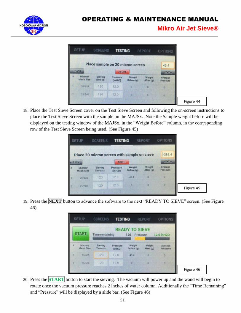
51
OPERATING & MAINTENANCE MANUAL
Mikro Air Jet Sieve®
18. Place the Test Sieve Screen cover on the Test Sieve Screen and following the on-screen instructions to
place the Test Sieve Screen with the sample on the MAJSx. Note the Sample weight before will be
displayed on the testing window of the MAJSx, in the “Weight Before” column, in the corresponding
row of the Test Sieve Screen being used. (See Figure 45)
19. Press the NEXT button to advance the software to the next “READY TO SIEVE” screen. (See Figure
46)
20. Press the START button to start the sieving. The vacuum will power up and the wand will begin to
rotate once the vacuum pressure reaches 2 inches of water column. Additionally the “Time Remaining”
and “Pressure” will be displayed by a slide bar. (See Figure 46)
Figure 44
Figure 45
Figure 46
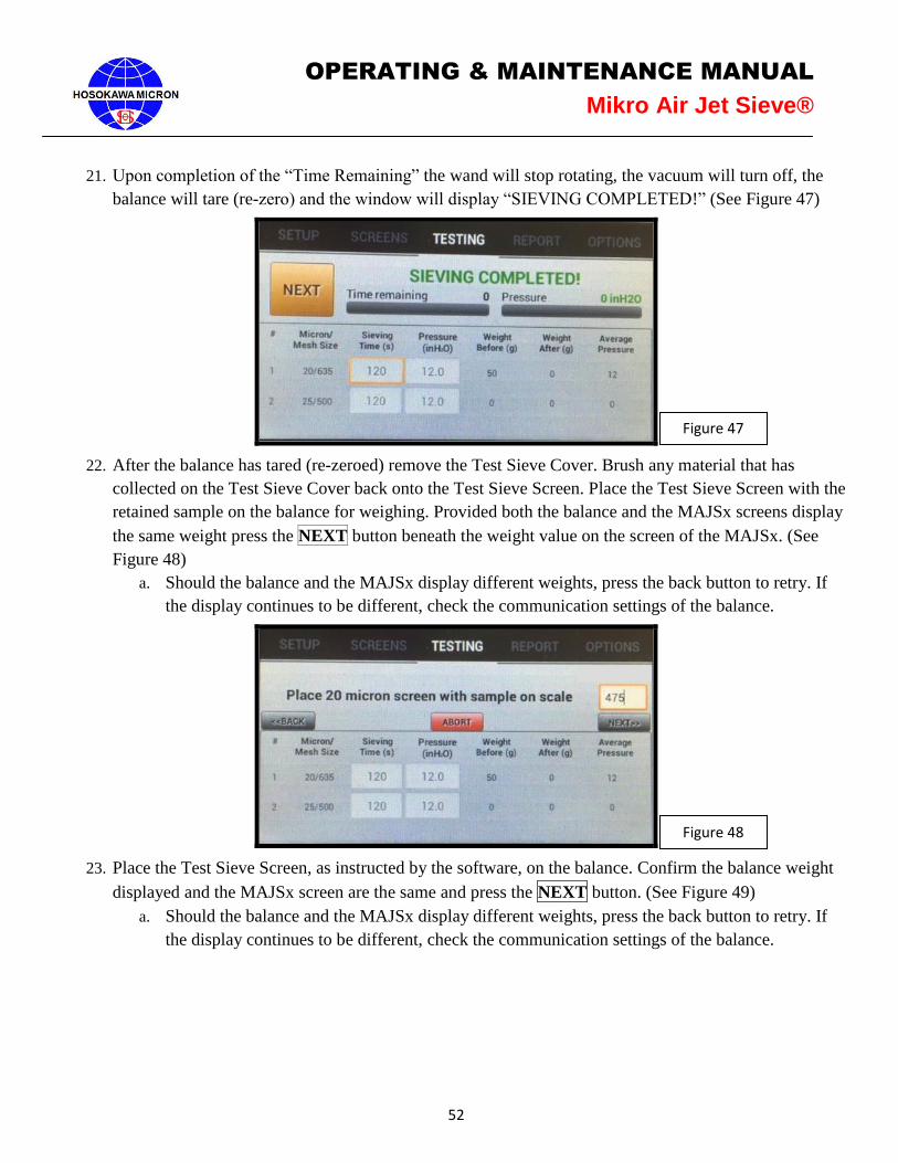
52
OPERATING & MAINTENANCE MANUAL
Mikro Air Jet Sieve®
21. Upon completion of the “Time Remaining” the wand will stop rotating, the vacuum will turn off, the
balance will tare (re-zero) and the window will display “SIEVING COMPLETED!” (See Figure 47)
22. After the balance has tared (re-zeroed) remove the Test Sieve Cover. Brush any material that has
collected on the Test Sieve Cover back onto the Test Sieve Screen. Place the Test Sieve Screen with the
retained sample on the balance for weighing. Provided both the balance and the MAJSx screens display
the same weight press the NEXT button beneath the weight value on the screen of the MAJSx. (See
Figure 48)
a. Should the balance and the MAJSx display different weights, press the back button to retry. If
the display continues to be different, check the communication settings of the balance.
23. Place the Test Sieve Screen, as instructed by the software, on the balance. Confirm the balance weight
displayed and the MAJSx screen are the same and press the NEXT button. (See Figure 49)
a. Should the balance and the MAJSx display different weights, press the back button to retry. If
the display continues to be different, check the communication settings of the balance.
Figure 47
Figure 48
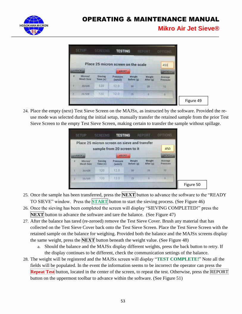
53
OPERATING & MAINTENANCE MANUAL
Mikro Air Jet Sieve®
24. Place the empty (next) Test Sieve Screen on the MAJSx, as instructed by the software. Provided the re-
use mode was selected during the initial setup, manually transfer the retained sample from the prior Test
Sieve Screen to the empty Test Sieve Screen, making certain to transfer the sample without spillage.
25. Once the sample has been transferred, press the NEXT button to advance the software to the “READY
TO SIEVE” window. Press the START button to start the sieving process. (See Figure 46)
26. Once the sieving has been completed the screen will display “SIEVING COMPLETED!” press the
NEXT button to advance the software and tare the balance. (See Figure 47)
27. After the balance has tared (re-zeroed) remove the Test Sieve Cover. Brush any material that has
collected on the Test Sieve Cover back onto the Test Sieve Screen. Place the Test Sieve Screen with the
retained sample on the balance for weighing. Provided both the balance and the MAJSx screens display
the same weight, press the NEXT button beneath the weight value. (See Figure 48)
a. Should the balance and the MAJSx display different weights, press the back button to retry. If
the display continues to be different, check the communication settings of the balance.
28. The weight will be registered and the MAJSx screen will display “TEST COMPLETE!” Note all the
fields will be populated. In the event the information seems to be incorrect the operator can press the
Repeat Test button, located in the center of the screen, to repeat the test. Otherwise, press the REPORT
button on the uppermost toolbar to advance within the software. (See Figure 51)
Figure 49
Figure 50
450
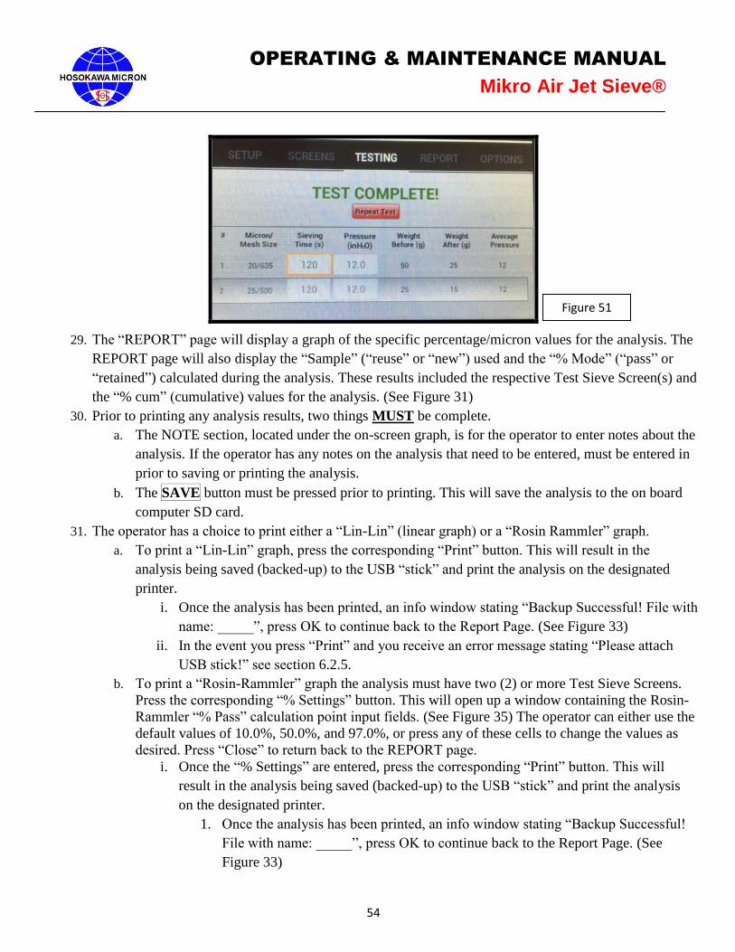
54
OPERATING & MAINTENANCE MANUAL
Mikro Air Jet Sieve®
29. The “REPORT” page will display a graph of the specific percentage/micron values for the analysis. The
REPORT page will also display the “Sample” (“reuse” or “new”) used and the “% Mode” (“pass” or
“retained”) calculated during the analysis. These results included the respective Test Sieve Screen(s) and
the “% cum” (cumulative) values for the analysis. (See Figure 31)
30. Prior to printing any analysis results, two things MUST be complete.
a. The NOTE section, located under the on-screen graph, is for the operator to enter notes about the
analysis. If the operator has any notes on the analysis that need to be entered, must be entered in
prior to saving or printing the analysis.
b. The SAVE button must be pressed prior to printing. This will save the analysis to the on board
computer SD card.
31. The operator has a choice to print either a “Lin-Lin” (linear graph) or a “Rosin Rammler” graph.
a. To print a “Lin-Lin” graph, press the corresponding “Print” button. This will result in the
analysis being saved (backed-up) to the USB “stick” and print the analysis on the designated
printer.
i. Once the analysis has been printed, an info window stating “Backup Successful! File with
name: _____”, press OK to continue back to the Report Page. (See Figure 33)
ii. In the event you press “Print” and you receive an error message stating “Please attach
USB stick!” see section 6.2.5.
b. To print a “Rosin-Rammler” graph the analysis must have two (2) or more Test Sieve Screens.
Press the corresponding “% Settings” button. This will open up a window containing the Rosin-
Rammler “% Pass” calculation point input fields. (See Figure 35) The operator can either use the
default values of 10.0%, 50.0%, and 97.0%, or press any of these cells to change the values as
desired. Press “Close” to return back to the REPORT page.
i. Once the “% Settings” are entered, press the corresponding “Print” button. This will
result in the analysis being saved (backed-up) to the USB “stick” and print the analysis
on the designated printer.
1. Once the analysis has been printed, an info window stating “Backup Successful!
File with name: _____”, press OK to continue back to the Report Page. (See
Figure 33)
Figure 51
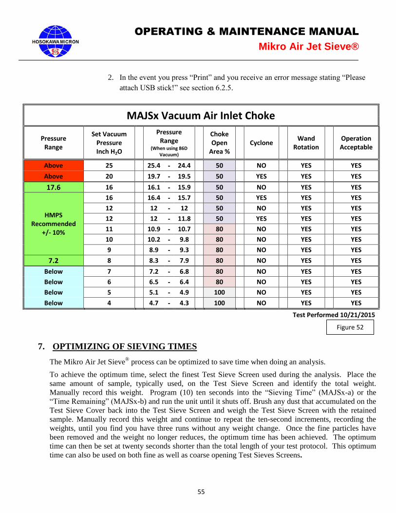
55
OPERATING & MAINTENANCE MANUAL
Mikro Air Jet Sieve®
2. In the event you press “Print” and you receive an error message stating “Please
attach USB stick!” see section 6.2.5.
MAJSx Vacuum Air Inlet Choke
Pressure Range
Set Vacuum Pressure Inch H2O
Pressure Range
(When using 86D Vacuum)
Choke Open
Area % Cyclone
Wand Rotation
Operation Acceptable
Above 25 25.4 - 24.4 50 NO YES YES
Above 20 19.7 - 19.5 50 YES YES YES
17.6 16 16.1 - 15.9 50 NO YES YES
HMPS Recommended
+/- 10%
16 16.4 - 15.7 50 YES YES YES
12 12 - 12 50 NO YES YES
12 12 - 11.8 50 YES YES YES
11 10.9 - 10.7 80 NO YES YES
10 10.2 - 9.8 80 NO YES YES
9 8.9 - 9.3 80 NO YES YES
7.2 8 8.3 - 7.9 80 NO YES YES
Below 7 7.2 - 6.8 80 NO YES YES
Below 6 6.5 - 6.4 80 NO YES YES
Below 5 5.1 - 4.9 100 NO YES YES
Below 4 4.7 - 4.3 100 NO YES YES
Test Performed 10/21/2015
7. OPTIMIZING OF SIEVING TIMES
The Mikro Air Jet Sieve®
process can be optimized to save time when doing an analysis.
To achieve the optimum time, select the finest Test Sieve Screen used during the analysis. Place the
same amount of sample, typically used, on the Test Sieve Screen and identify the total weight.
Manually record this weight. Program (10) ten seconds into the “Sieving Time” (MAJSx-a) or the
“Time Remaining” (MAJSx-b) and run the unit until it shuts off. Brush any dust that accumulated on the
Test Sieve Cover back into the Test Sieve Screen and weigh the Test Sieve Screen with the retained
sample. Manually record this weight and continue to repeat the ten-second increments, recording the
weights, until you find you have three runs without any weight change. Once the fine particles have
been removed and the weight no longer reduces, the optimum time has been achieved. The optimum
time can then be set at twenty seconds shorter than the total length of your test protocol. This optimum
time can also be used on both fine as well as coarse opening Test Sieves Screens.
Figure 52

56
OPERATING & MAINTENANCE MANUAL
Mikro Air Jet Sieve®
8. MAINTENANCE
8.1 Disassembly and Cleaning
a) The information contained here-in is intended to be a guide ONLY. Frequency and extent of cleaning
depends on the user’s corporate policy, regularity of use, material and environment.
b) Remove as much dry powder using a vacuum prior to starting the cleaning process.
c) Switch the MAJSx to the “Off” position, then un-plug the Jet Sieve from the power source and remove
the power cable on the body.
d) Using a sponge, cloth, etc., lightly wash the pan area of the MAJSx. Care should be used NOT to
oversaturate the area so that liquid collects in the pan or discharge duct. An excessive amount of liquid
will damage internal electrical and mechanical components. If a scourer or hard bristle brush, etc. is
used, this may effect or damage the MAJSx pan or discharge area. As a result CAUTION must be used.
e) Recommended Air Jet Sieve Housing cleansing can be performed by either dry vacuum and or with a
damp towel using a mild non-corrosive / non-abrasive solution. In the event the damp process is used,
CAUTION should be taken in selecting the solution so there is no reaction with any remaining powder
residue.
f) The exterior of the MAJSx is to be wiped down using either the dry or damp cloth method. Under NO
circumstance is the unit to be submerged or saturated with liquid.
g) In the event the damp cloth process is used, the Air Jet Sieve should be permitted to dry thoroughly prior
to resuming use of the instrument.
h) Under NO circumstances is the MAJSx to be subjected to steam sterilization.
i) If authorized, remove the (4) mounting feet and the bottom plate. Replace and/or inspect and clean, if
required, the vacuum pressure protective filter.
Hosokawa Micron Powder Systems accepts no responsibility for damage to the instrument
resulting from the cleaning process and/or misuse of cleaning solutions.
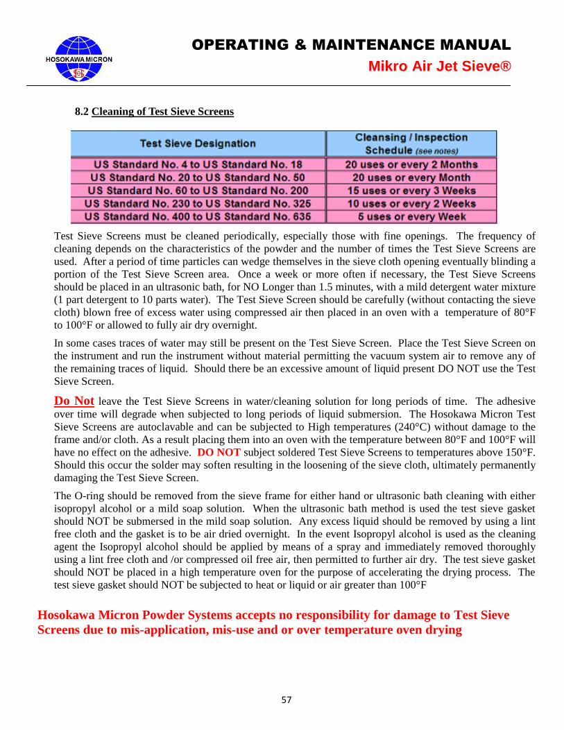
57
OPERATING & MAINTENANCE MANUAL
Mikro Air Jet Sieve®
8.2 Cleaning of Test Sieve Screens
Test Sieve Screens must be cleaned periodically, especially those with fine openings. The frequency of
cleaning depends on the characteristics of the powder and the number of times the Test Sieve Screens are
used. After a period of time particles can wedge themselves in the sieve cloth opening eventually blinding a
portion of the Test Sieve Screen area. Once a week or more often if necessary, the Test Sieve Screens
should be placed in an ultrasonic bath, for NO Longer than 1.5 minutes, with a mild detergent water mixture
(1 part detergent to 10 parts water). The Test Sieve Screen should be carefully (without contacting the sieve
cloth) blown free of excess water using compressed air then placed in an oven with a temperature of 80°F
to 100°F or allowed to fully air dry overnight.
In some cases traces of water may still be present on the Test Sieve Screen. Place the Test Sieve Screen on
the instrument and run the instrument without material permitting the vacuum system air to remove any of
the remaining traces of liquid. Should there be an excessive amount of liquid present DO NOT use the Test
Sieve Screen.
Do Not leave the Test Sieve Screens in water/cleaning solution for long periods of time. The adhesive
over time will degrade when subjected to long periods of liquid submersion. The Hosokawa Micron Test
Sieve Screens are autoclavable and can be subjected to High temperatures (240°C) without damage to the
frame and/or cloth. As a result placing them into an oven with the temperature between 80°F and 100°F will
have no effect on the adhesive. DO NOT subject soldered Test Sieve Screens to temperatures above 150°F.
Should this occur the solder may soften resulting in the loosening of the sieve cloth, ultimately permanently
damaging the Test Sieve Screen.
The O-ring should be removed from the sieve frame for either hand or ultrasonic bath cleaning with either
isopropyl alcohol or a mild soap solution. When the ultrasonic bath method is used the test sieve gasket
should NOT be submersed in the mild soap solution. Any excess liquid should be removed by using a lint
free cloth and the gasket is to be air dried overnight. In the event Isopropyl alcohol is used as the cleaning
agent the Isopropyl alcohol should be applied by means of a spray and immediately removed thoroughly
using a lint free cloth and /or compressed oil free air, then permitted to further air dry. The test sieve gasket
should NOT be placed in a high temperature oven for the purpose of accelerating the drying process. The
test sieve gasket should NOT be subjected to heat or liquid or air greater than 100°F
Hosokawa Micron Powder Systems accepts no responsibility for damage to Test Sieve
Screens due to mis-application, mis-use and or over temperature oven drying
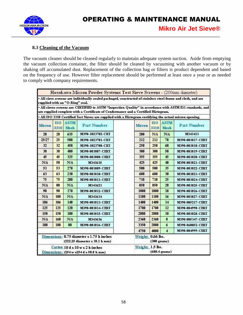
58
OPERATING & MAINTENANCE MANUAL
Mikro Air Jet Sieve®
8.3 Cleaning of the Vacuum
The vacuum cleaner should be cleaned regularly to maintain adequate system suction. Aside from emptying
the vacuum collection container, the filter should be cleaned by vacuuming with another vacuum or by
shaking off accumulated dust. Replacement of the collection bag or filters is product dependent and based
on the frequency of use. However filter replacement should be performed at least once a year or as needed
to comply with company requirements.
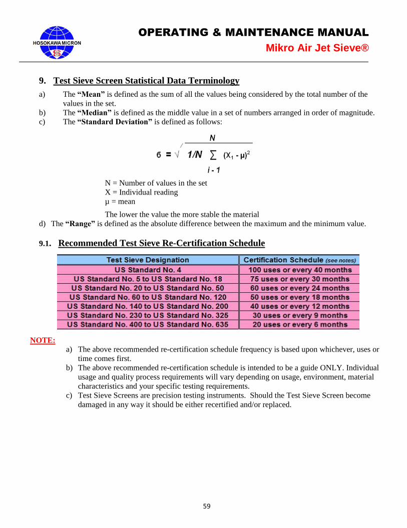
59
OPERATING & MAINTENANCE MANUAL
Mikro Air Jet Sieve®
9. Test Sieve Screen Statistical Data Terminology
a) The “Mean” is defined as the sum of all the values being considered by the total number of the
values in the set.
b) The “Median” is defined as the middle value in a set of numbers arranged in order of magnitude.
c) The “Standard Deviation” is defined as follows:
N = Number of values in the set
X = Individual reading
µ = mean
The lower the value the more stable the material
d) The “Range” is defined as the absolute difference between the maximum and the minimum value.
9.1. Recommended Test Sieve Re-Certification Schedule
NOTE:
a) The above recommended re-certification schedule frequency is based upon whichever, uses or
time comes first.
b) The above recommended re-certification schedule is intended to be a guide ONLY. Individual
usage and quality process requirements will vary depending on usage, environment, material
characteristics and your specific testing requirements.
c) Test Sieve Screens are precision testing instruments. Should the Test Sieve Screen become
damaged in any way it should be either recertified and/or replaced.

60
OPERATING & MAINTENANCE MANUAL
Mikro Air Jet Sieve®
10. TROUBLESHOOTING
Problem Potential Solution
Cannot reach or maintain the desired
Vacuum Pressure. The vacuum cleaner needs to be cleaned. Replace ALL
vacuum filters.
The air adjust gate internally between the inlet
and outlet duct needs to be cleaned.
The vacuum hose connection or vacuum hose is not
installed correctly. Check and tighten.
Confirm that the proper choke percentage disc is in
place on the Air Inlet.
The Vacuum Pressure exceeds the
recommended operation range “8 to 16”
inches water column.
Install an additional air by-pass slide gate on the inlet
air duct located on the back of the MAJSx housing.
It is taking longer to sieve samples. Inspect the sieve cloth by holding up to a light and look
for blinding of the openings. Test Sieve Screen has to be
cleaned in the ultrasonic cleaner.
The sample material is very electro- static. It
clings to the Polycarbonate Sieve Cover. Spray an anti-static agent on the Test Sieve Cover and
dry with a paper towel.
Unit will not operate. Make sure power supply cord is connected to power
receptacle.
Check for open-circuit breaker.
The software is not communicating with the
between the MAJSx and the balance. Confirm the installation of the proper RS232 cable.
Confirm the balance default communication settings.
The IP Address is not display on the Options
Screen. The instrument is not connected to the network.
Confirm the network cable is properly connected to the
MAJSx.
Confirmed that the network cable is live.
Power down the MAJSx, wait approximately 15-20
seconds before attempting to re-energize the MAJSx.
Confirm the network signal strength by connecting a
network power switch.
Cannot print Confirm the USB “stick” is in place (max 4 gb).
Confirm the Printer IP Address was properly saved.
Android desk top displayed
(Blank screen with button on the right side) Power off and wait approximately 15-20 seconds before
attempting to re-energize the MAJSx
61
OPERATING & MAINTENANCE MANUAL
Mikro Air Jet Sieve®
11. CRITICAL INSTRUMENT VERIFICATION
11.1 Verification of Vacuum Gauge
Place a modified Test Sieve Cover on the unit. Connect a Certified External Pressure Gauge to the
modified Test Sieve Screen Cover and place the cover on the MAJSx housing. Select the "OPTIONS"
page on the right side of the top tool bar. Scroll down and select the "DIAGNOSTICS" cell. Under
Motor Test, enter in a desired target pressure. Once the Target Pressure is registered, press the Motor
Test START button. Record and compare the "Actual Pressure" on the MAJSx display as well as the
reading on the External Pressure Gauge. It should be ± (2) two inches of water column.
11.2 Verification of Timer
Use a NIST certified Stop Watch to verify the times. Place a Test Sieve Screen Cover on the housing of
the MAJSx. Set the "Sieving Time" (MAJSx-a) or “Time Remaining” (MAJSx-b) on the MAJSx display
at 60 seconds and press START. Once the desired Vacuum Pressure is achieved, the MAJSx air wand
will begin to rotate. Simultaneously press Start on the Stop Watch as the air wand begins to rotate.
Allow the "Time Remaining" to count down to zero. Simultaneously press stop on the Stop Watch once
the MAJSx reaches zero. The stop watch should read 1:00 minute (60 seconds) ± 1.0% or 0.6 seconds.
Note: If any of the values are out of range the unit MUST be returned for factory calibration.
It is recommended that the verification of the vacuum gauge and timer take place at a minimum
of every twelve (12) months.
11.3 Calibration of Test Sieve Screens
All Test Sieve Screens come with a (histogram) certificate of accurate calibration. This certificate
should be kept on file for reference. It is recommended that a second set of certified Test Sieve Screens
are purchased and used solely for the purpose of confirming the accuracy of the Test Sieve Screens.
Refer to page 59 for the recommended recertification schedule.
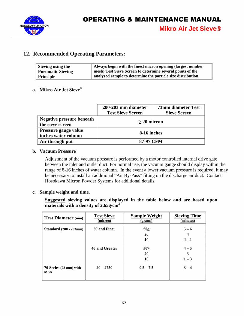
62
OPERATING & MAINTENANCE MANUAL
Mikro Air Jet Sieve®
12. Recommended Operating Parameters:
Sieving using the
Pneumatic Sieving
Principle
Always begin with the finest micron opening (largest number
mesh) Test Sieve Screen to determine several points of the
analyzed sample to determine the particle size distribution
a. Mikro Air Jet Sieve®
200-203 mm diameter
Test Sieve Screen
73mm diameter Test
Sieve Screen
Negative pressure beneath
the sieve screen ≥ 20 micron
Pressure gauge value
inches water column 8-16 inches
Air through put 87-97 CFM
b. Vacuum Pressure
Adjustment of the vacuum pressure is performed by a motor controlled internal drive gate
between the inlet and outlet duct. For normal use, the vacuum gauge should display within the
range of 8-16 inches of water column. In the event a lower vacuum pressure is required, it may
be necessary to install an additional “Air By-Pass” fitting on the discharge air duct. Contact
Hosokawa Micron Powder Systems for additional details.
c. Sample weight and time.
Suggested sieving values are displayed in the table below and are based upon
materials with a density of 2.65g/cm3
Test Diameter (mm) Test Sieve (micron)
Sample Weight (grams)
Sieving Time (minutes)
Standard (200 - 203mm) 39 and Finer 50≥ 5 – 6
20 4
10 1 - 4
40 and Greater 50≥ 4 – 5
20 3
10 1 – 3
70 Series (73 mm) with
MSA 20 – 4750 0.5 – 7.5 3 – 4

63
OPERATING & MAINTENANCE MANUAL
Mikro Air Jet Sieve®
d. Sieving with difficult material
Sample Characteristic Counter Action
Hygroscopic Use conditioned air
Dry the sample before and after analysis
Shorten sieving time
Electrostatic In some cases it is preferred to mix an anti-static agent with the sample.
Hosokawa Micron Powder Systems suggests adding approximately 2%
(sample weight) of “High Purity Silicon Dioxide”, which will adhere to
the surface of the larger particles and act as a barrier thus reducing
particle to particle cohesion which ultimately affects the static charge on
the sample. In addition the use of a light coating of anti-static spray on
the Test Sieve Cover and the Test Sieve frame will reduce the
electrostatic effect on these parts. Caution should be taken to not get the
antistatic spray on the screen cloth.
Sticky Even with MAJSx, difficulties sometime occur when sieving extremely
fine or fatty materials. The addition of “Highly Dispersed Silica” has
shown to reduce and/or eliminate these difficulties.
13. Instructions for the Hose connection of a Cyclone to the MAJSx
In order to attach a cyclone to the MAJSx please adhere to the following steps:
1. Remove the vacuum hose from the back “VACUUM” nozzle of the MAJSx.
2. Attached one end of the supplied Cyclone hose to the “VACUUM” nozzle of the
MAJSx.
3. Attach the opposite end of the Cyclone hose to the inlet of the Cyclone, typically the
side inlet of the Cyclone.
4. Attach the end of the vacuum hose to the discharge port of the Cyclone, typically the
top of the Cyclone.
5. Depending upon the type of Cyclone used it may be necessary to use a hose
transition. If this is the case place the transition into each of the cyclone openings
and connect the respective hose to the transitions.
6. Attach the product collection jar and confirm that there are no air leaks. Leaks will
affect the efficiency of the Cyclone.
7. Follow the instruction included with the Cyclone for proper mounting and placement
of the Cyclone.
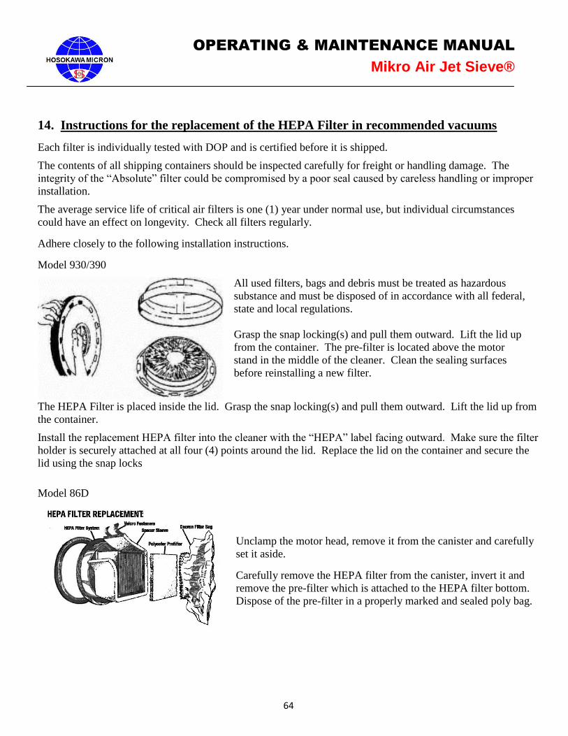
64
OPERATING & MAINTENANCE MANUAL
Mikro Air Jet Sieve®
14. Instructions for the replacement of the HEPA Filter in recommended vacuums
Each filter is individually tested with DOP and is certified before it is shipped.
The contents of all shipping containers should be inspected carefully for freight or handling damage. The
integrity of the “Absolute” filter could be compromised by a poor seal caused by careless handling or improper
installation.
The average service life of critical air filters is one (1) year under normal use, but individual circumstances
could have an effect on longevity. Check all filters regularly.
Adhere closely to the following installation instructions.
Model 930/390
All used filters, bags and debris must be treated as hazardous
substance and must be disposed of in accordance with all federal,
state and local regulations.
Grasp the snap locking(s) and pull them outward. Lift the lid up
from the container. The pre-filter is located above the motor
stand in the middle of the cleaner. Clean the sealing surfaces
before reinstalling a new filter.
The HEPA Filter is placed inside the lid. Grasp the snap locking(s) and pull them outward. Lift the lid up from
the container.
Install the replacement HEPA filter into the cleaner with the “HEPA” label facing outward. Make sure the filter
holder is securely attached at all four (4) points around the lid. Replace the lid on the container and secure the
lid using the snap locks
Model 86D
Unclamp the motor head, remove it from the canister and carefully
set it aside.
Carefully remove the HEPA filter from the canister, invert it and
remove the pre-filter which is attached to the HEPA filter bottom.
Dispose of the pre-filter in a properly marked and sealed poly bag.
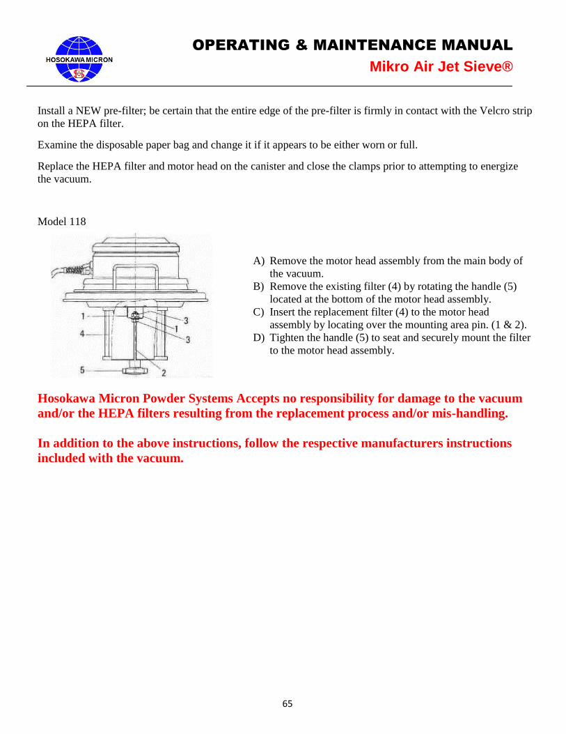
65
OPERATING & MAINTENANCE MANUAL
Mikro Air Jet Sieve®
Install a NEW pre-filter; be certain that the entire edge of the pre-filter is firmly in contact with the Velcro strip
on the HEPA filter.
Examine the disposable paper bag and change it if it appears to be either worn or full.
Replace the HEPA filter and motor head on the canister and close the clamps prior to attempting to energize
the vacuum.
Model 118
A) Remove the motor head assembly from the main body of
the vacuum.
B) Remove the existing filter (4) by rotating the handle (5)
located at the bottom of the motor head assembly.
C) Insert the replacement filter (4) to the motor head
assembly by locating over the mounting area pin. (1 & 2).
D) Tighten the handle (5) to seat and securely mount the filter
to the motor head assembly.
Hosokawa Micron Powder Systems Accepts no responsibility for damage to the vacuum
and/or the HEPA filters resulting from the replacement process and/or mis-handling.
In addition to the above instructions, follow the respective manufacturers instructions
included with the vacuum.

66
OPERATING & MAINTENANCE MANUAL
Mikro Air Jet Sieve®
Aftermarket Spare Parts Contact
Steve Brush Fred Scott John Stonaker Dan Vara
908-277-9340 908-277-9313 908-277-9204 908-277-9200
[email protected] [email protected] [email protected] [email protected]
Alaska Alabama Illinois Arizona
Arkansas Connecticut Indiana California
Colorado Delaware Iowa Nevada
Hawaii Florida Kentucky New Mexico
Idaho Georgia Michigan Oregon
Kansas Maine Minnesota Washington
Louisiana Maryland Missouri Missouri Massachusetts Ohio Mexico
Montana Mississippi Wisconsin Central America
North Dakota North Carolina
Puerto Rico
Nebraska New Hampshire
South America
Oklahoma New Jersey
Canada
South Dakota New York Texas Pennsylvania Utah Rhode Island Wyoming South Carolina
Tennessee
Vermont
Virginia
West Virginia
Air Jet Sieve Repairs Contact
Ginny Koleda
908-277-9249 [email protected]
Leia Campbell
908-277-9331 [email protected]
Tim Calvo
908-277-9215 [email protected]