Embed Size (px)
Citation preview
Installation &Operation Instructions
312 TEESET™
Maintenance Training Manual
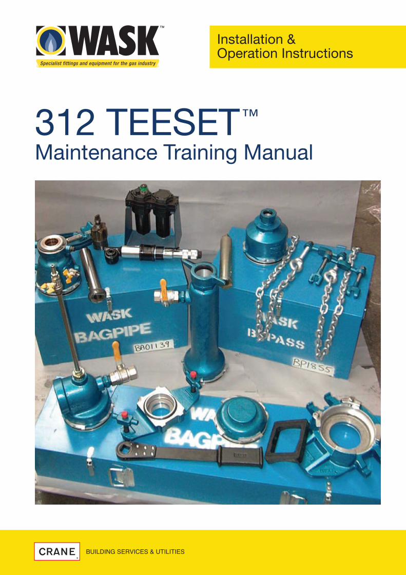
CONTENTS
02 WASK 312 TEESET™ MAINTENANCE TRAINING MANUAL
1.0 Background3. Parts Identification4. Servicing Statement4. Service Facility
2.0 Maintenance Procedure – Stage One5. Inspection5. Stripping Down7. Cleaning
3.0 Maintenance Procedure – Stage Two10. Blue seal replacement11. Pivot Stud and Valve plate replacement13. Vent/lock Plunger replacement14. Resealing the base
4.0 Maintenance procedure other parts17. Drilling Head (all types)18. Fitting Head19. Bagging Head20. Bypass Head21. Blanking Cap22. Inspection Head23. PE Undercarriage23. Control Handle24. Bag Tube25. PE Plug Spindle25. Drilling and Fitting Spindle26. Double Chains26. 2 Part Tee Stopper Tool27. Non serviceable items
5.0 Waste disposal policy29. Appendix A - Recommended Tools list30. Appendix B - Recommended Spares list31. Appendix C - Pressure Test procedure36. Appendix D - Retro Fit Interlocking Pressure Probe
WASK 312 Teeset™ Maintenance Training Manual
www.wask-uk.com Issue 2 16/03/11
3
1. BACKGROUND 1.1 WASK 312 drilling equipment has been in operation for over 30 years. 1.2 Fundamentally, the design has not changed over that period. 1.3 Regular maintenance of the equipment is essential for safe and
efficient usage of the equipment.
NOTE! The duration between service intervals is wholly dependant upon usage and local procedures. WASK do however recommend a maximum of 12 months between services and preferably 6 months, if used regularly.
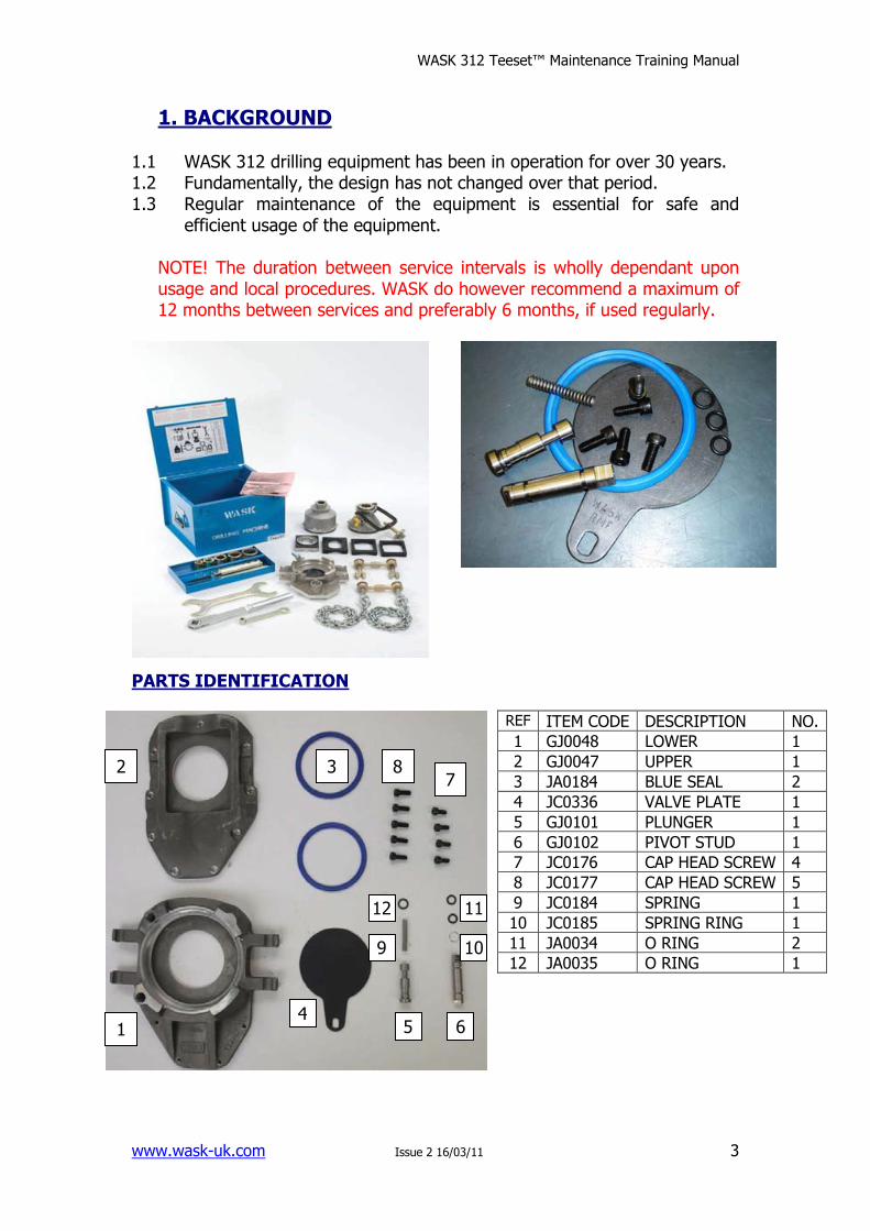
PARTS IDENTIFICATION
REF ITEM CODE DESCRIPTION NO.
1 GJ0048 LOWER 1
2 GJ0047 UPPER 1
3 JA0184 BLUE SEAL 2
4 JC0336 VALVE PLATE 1
5 GJ0101 PLUNGER 1
6 GJ0102 PIVOT STUD 1
7 JC0176 CAP HEAD SCREW 4
8 JC0177 CAP HEAD SCREW 5
9 JC0184 SPRING 1
10 JC0185 SPRING RING 1
11 JA0034 O RING 2
12 JA0035 O RING 1
2 3
1
8 7
11 12
10
6 5
9
4
WASK 312 Teeset™ Maintenance Training Manual
www.wask-uk.com Issue 2 16/03/11
4
SERVICING STATEMENT 1.4 To ensure that the Teeset™ base works safely and efficiently, servicing
is required 1.5 Servicing shall only be carried out by competent operatives 1.6 Servicing shall only be carried out in approved centres
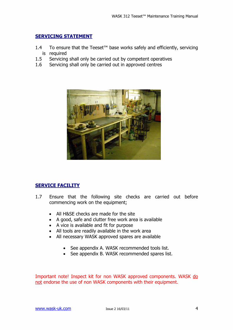
SERVICE FACILITY 1.7 Ensure that the following site checks are carried out before
commencing work on the equipment;
• All H&SE checks are made for the site • A good, safe and clutter free work area is available • A vice is available and fit for purpose • All tools are readily available in the work area • All necessary WASK approved spares are available
• See appendix A. WASK recommended tools list. • See appendix B. WASK recommended spares list.
Important note! Inspect kit for non WASK approved components. WASK do not endorse the use of non WASK components with their equipment.
WASK 312 Teeset™ Maintenance Training Manual
www.wask-uk.com Issue 2 16/03/11
5
2. MAINTENANCE – STAGE ONE
Inspection
2.1 Clean thoroughly the external surfaces of the base and remove any debris internally where possible i.e. vent/lock hole. Check the base externally for damage i.e. cracks, impact marks, missing features or parts.
2.2 Note- if ‘hot washing’ the equipment, only utilise an industrial hot wash machine- do not shot blast as this could damage the cast body. Do not hot wash control handle assembly’s.
2.3 If there are any cracks or missing features (broken castings) the base CANNOT be repaired.
2.4 If visually in good order the base should be pressure tested at 3 bar. This test is carried out to establish if the sealing recess is in good order. Follow test procedure 15-17 in appendix C.
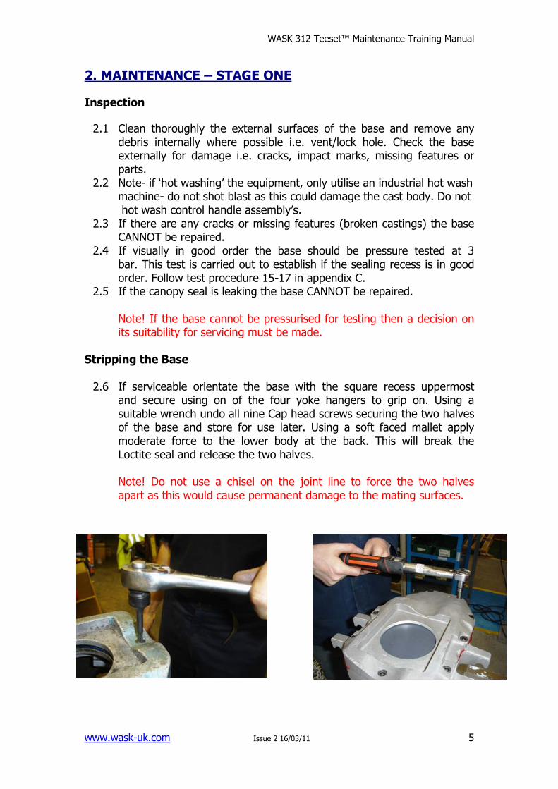
2.5 If the canopy seal is leaking the base CANNOT be repaired. Note! If the base cannot be pressurised for testing then a decision on its suitability for servicing must be made. Stripping the Base 2.6 If serviceable orientate the base with the square recess uppermost
and secure using on of the four yoke hangers to grip on. Using a suitable wrench undo all nine Cap head screws securing the two halves of the base and store for use later. Using a soft faced mallet apply moderate force to the lower body at the back. This will break the Loctite seal and release the two halves.
Note! Do not use a chisel on the joint line to force the two halves apart as this would cause permanent damage to the mating surfaces.
WASK 312 Teeset™ Maintenance Training Manual
www.wask-uk.com Issue 2 16/03/11
6
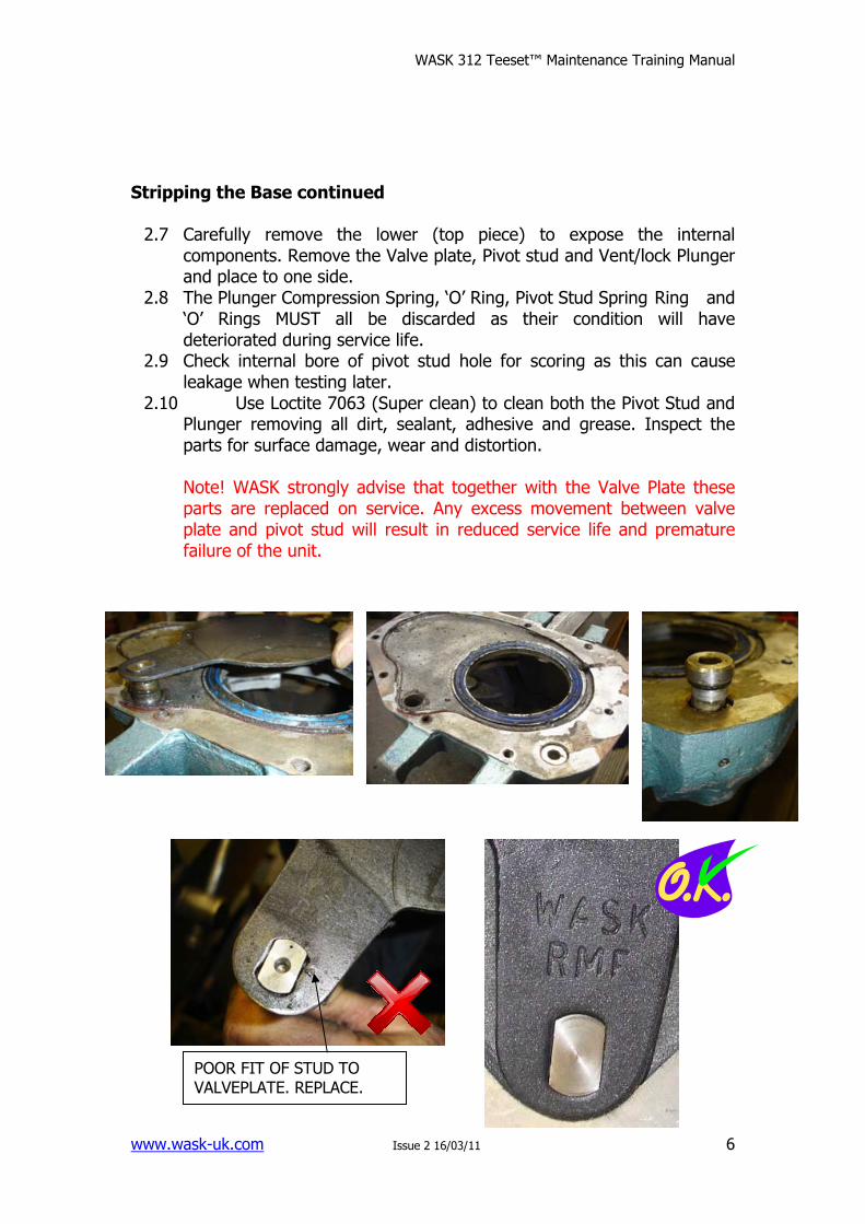
Stripping the Base continued 2.7 Carefully remove the lower (top piece) to expose the internal
components. Remove the Valve plate, Pivot stud and Vent/lock Plunger and place to one side.
2.8 The Plunger Compression Spring, ‘O’ Ring, Pivot Stud Spring Ring and ‘O’ Rings MUST all be discarded as their condition will have deteriorated during service life.
2.9 Check internal bore of pivot stud hole for scoring as this can cause leakage when testing later.
2.10 Use Loctite 7063 (Super clean) to clean both the Pivot Stud and Plunger removing all dirt, sealant, adhesive and grease. Inspect the parts for surface damage, wear and distortion.
Note! WASK strongly advise that together with the Valve Plate these parts are replaced on service. Any excess movement between valve plate and pivot stud will result in reduced service life and premature failure of the unit.
POOR FIT OF STUD TO VALVEPLATE. REPLACE. WORN VALVE
WASK 312 Teeset™ Maintenance Training Manual
www.wask-uk.com Issue 2 16/03/11
7
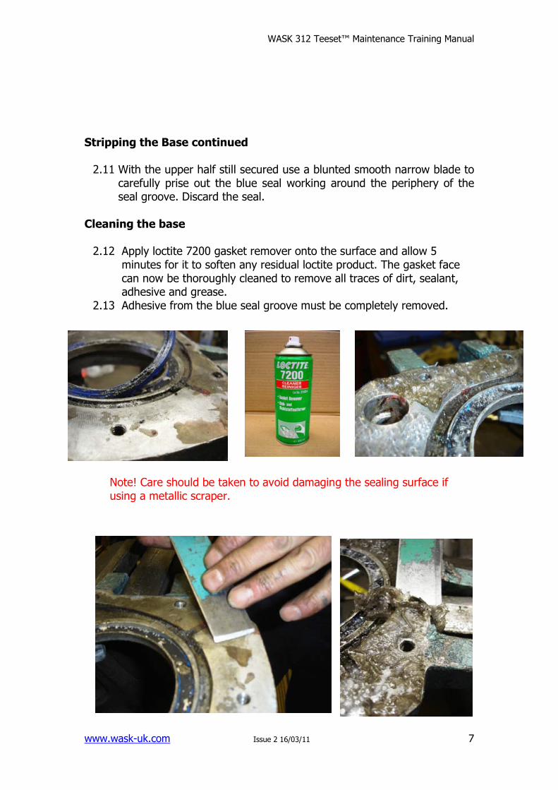
Stripping the Base continued 2.11 With the upper half still secured use a blunted smooth narrow blade to
carefully prise out the blue seal working around the periphery of the seal groove. Discard the seal.
Cleaning the base 2.12 Apply loctite 7200 gasket remover onto the surface and allow 5
minutes for it to soften any residual loctite product. The gasket face can now be thoroughly cleaned to remove all traces of dirt, sealant, adhesive and grease.
2.13 Adhesive from the blue seal groove must be completely removed.
Note! Care should be taken to avoid damaging the sealing surface if using a metallic scraper.
WASK 312 Teeset™ Maintenance Training Manual
www.wask-uk.com Issue 2 16/03/11
8
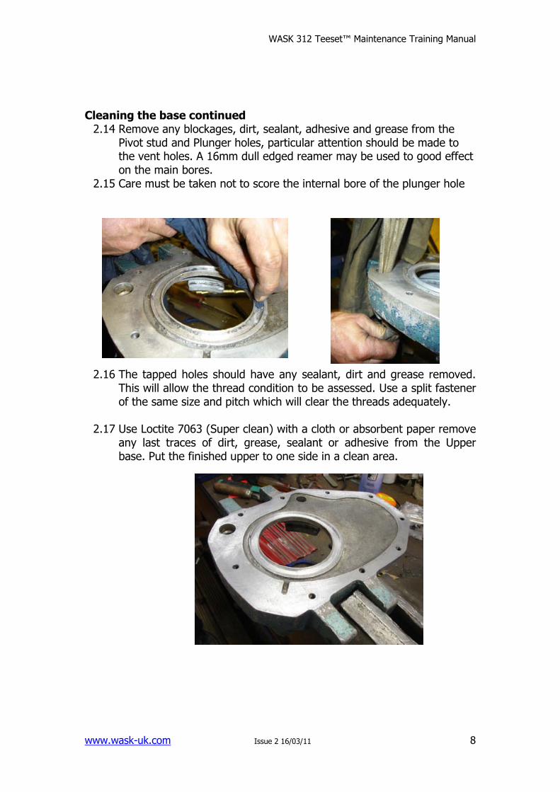
Cleaning the base continued 2.14 Remove any blockages, dirt, sealant, adhesive and grease from the
Pivot stud and Plunger holes, particular attention should be made to the vent holes. A 16mm dull edged reamer may be used to good effect on the main bores.
2.15 Care must be taken not to score the internal bore of the plunger hole 2.16 The tapped holes should have any sealant, dirt and grease removed.
This will allow the thread condition to be assessed. Use a split fastener of the same size and pitch which will clear the threads adequately.
2.17 Use Loctite 7063 (Super clean) with a cloth or absorbent paper remove
any last traces of dirt, grease, sealant or adhesive from the Upper base. Put the finished upper to one side in a clean area.
WASK 312 Teeset™ Maintenance Training Manual
www.wask-uk.com Issue 2 16/03/11
9
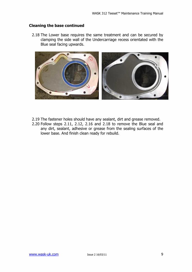
Cleaning the base continued 2.18 The Lower base requires the same treatment and can be secured by
clamping the side wall of the Undercarriage recess orientated with the Blue seal facing upwards.
2.19 The fastener holes should have any sealant, dirt and grease removed. 2.20 Follow steps 2.11, 2.12, 2.16 and 2.18 to remove the Blue seal and
any dirt, sealant, adhesive or grease from the sealing surfaces of the lower base. And finish clean ready for rebuild.
WASK 312 Teeset™ Maintenance Training Manual
www.wask-uk.com Issue 2 16/03/11
10
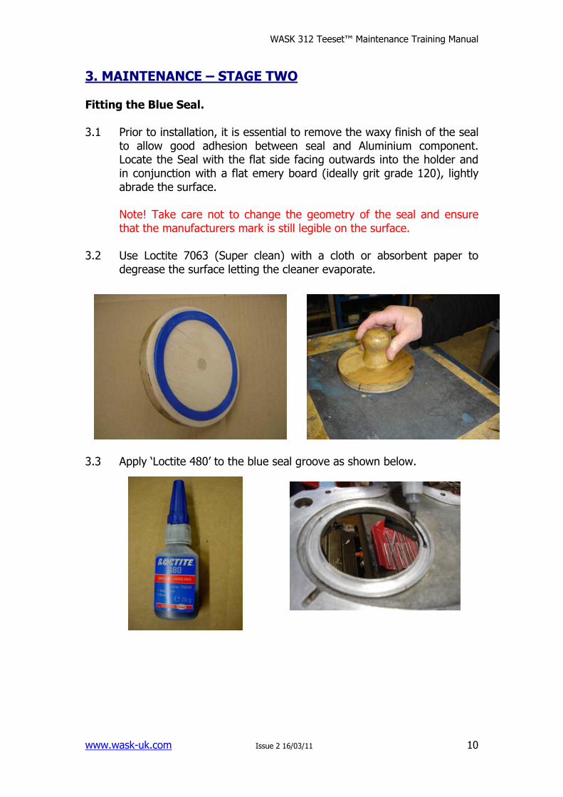
3. MAINTENANCE – STAGE TWO Fitting the Blue Seal. 3.1 Prior to installation, it is essential to remove the waxy finish of the seal
to allow good adhesion between seal and Aluminium component. Locate the Seal with the flat side facing outwards into the holder and in conjunction with a flat emery board (ideally grit grade 120), lightly abrade the surface.
Note! Take care not to change the geometry of the seal and ensure that the manufacturers mark is still legible on the surface.
3.2 Use Loctite 7063 (Super clean) with a cloth or absorbent paper to
degrease the surface letting the cleaner evaporate.
3.3 Apply ‘Loctite 480’ to the blue seal groove as shown below.
WASK 312 Teeset™ Maintenance Training Manual
www.wask-uk.com Issue 2 16/03/11
11
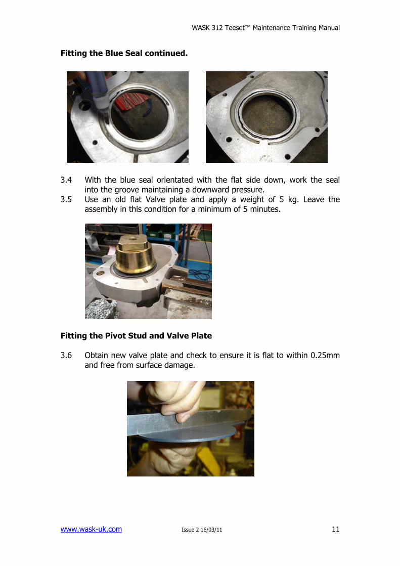
Fitting the Blue Seal continued. 3.4 With the blue seal orientated with the flat side down, work the seal
into the groove maintaining a downward pressure. 3.5 Use an old flat Valve plate and apply a weight of 5 kg. Leave the
assembly in this condition for a minimum of 5 minutes.
Fitting the Pivot Stud and Valve Plate 3.6 Obtain new valve plate and check to ensure it is flat to within 0.25mm
and free from surface damage.
WASK 312 Teeset™ Maintenance Training Manual
www.wask-uk.com Issue 2 16/03/11
12
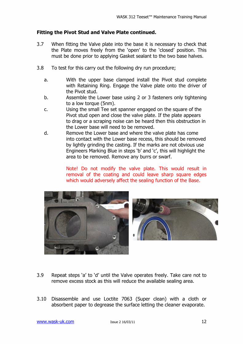
Fitting the Pivot Stud and Valve Plate continued. 3.7 When fitting the Valve plate into the base it is necessary to check that
the Plate moves freely from the ‘open’ to the ‘closed’ position. This must be done prior to applying Gasket sealant to the two base halves.
3.8 To test for this carry out the following dry run procedure;
a. With the upper base clamped install the Pivot stud complete
with Retaining Ring. Engage the Valve plate onto the driver of the Pivot stud.
b. Assemble the Lower base using 2 or 3 fasteners only tightening to a low torque (5nm).
c. Using the small Tee set spanner engaged on the square of the Pivot stud open and close the valve plate. If the plate appears to drag or a scraping noise can be heard then this obstruction in the Lower base will need to be removed.
d. Remove the Lower base and where the valve plate has come into contact with the Lower base recess, this should be removed by lightly grinding the casting. If the marks are not obvious use Engineers Marking Blue in steps ‘b’ and ‘c’, this will highlight the area to be removed. Remove any burrs or swarf.
Note! Do not modify the valve plate. This would result in removal of the coating and could leave sharp square edges which would adversely affect the sealing function of the Base.
3.9 Repeat steps ‘a’ to ‘d’ until the Valve operates freely. Take care not to
remove excess stock as this will reduce the available sealing area. 3.10 Disassemble and use Loctite 7063 (Super clean) with a cloth or
absorbent paper to degrease the surface letting the cleaner evaporate.
WASK 312 Teeset™ Maintenance Training Manual
www.wask-uk.com Issue 2 16/03/11
13
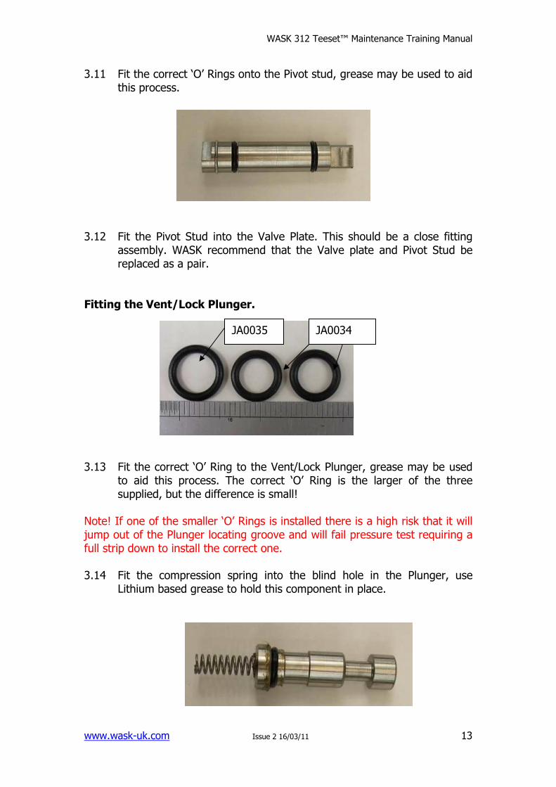
3.11 Fit the correct ‘O’ Rings onto the Pivot stud, grease may be used to aid this process.
3.12 Fit the Pivot Stud into the Valve Plate. This should be a close fitting
assembly. WASK recommend that the Valve plate and Pivot Stud be replaced as a pair.
Fitting the Vent/Lock Plunger. 3.13 Fit the correct ‘O’ Ring to the Vent/Lock Plunger, grease may be used
to aid this process. The correct ‘O’ Ring is the larger of the three supplied, but the difference is small!
Note! If one of the smaller ‘O’ Rings is installed there is a high risk that it will jump out of the Plunger locating groove and will fail pressure test requiring a full strip down to install the correct one. 3.14 Fit the compression spring into the blind hole in the Plunger, use
Lithium based grease to hold this component in place.
JA0034 JA0035
WASK 312 Teeset™ Maintenance Training Manual
www.wask-uk.com Issue 2 16/03/11
14
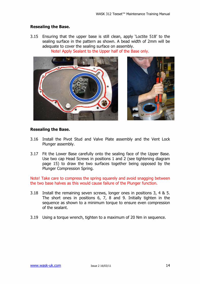
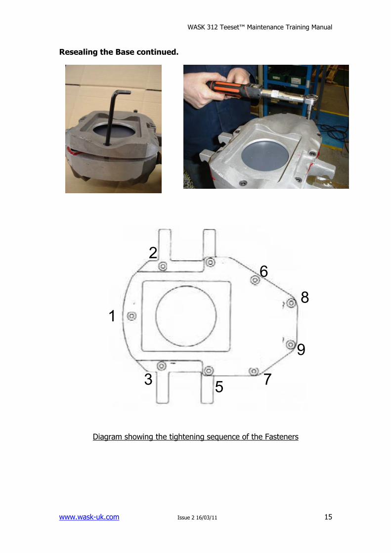
Resealing the Base. 3.15 Ensuring that the upper base is still clean, apply ‘Loctite 518’ to the
sealing surface in the pattern as shown. A bead width of 2mm will be adequate to cover the sealing surface on assembly.
Note! Apply Sealant to the Upper half of the Base only.
Resealing the Base. 3.16 Install the Pivot Stud and Valve Plate assembly and the Vent Lock
Plunger assembly. 3.17 Fit the Lower Base carefully onto the sealing face of the Upper Base.
Use two cap Head Screws in positions 1 and 2 (see tightening diagram page 15) to draw the two surfaces together being opposed by the Plunger Compression Spring.
Note! Take care to compress the spring squarely and avoid snagging between the two base halves as this would cause failure of the Plunger function. 3.18 Install the remaining seven screws, longer ones in positions 3, 4 & 5.
The short ones in positions 6, 7, 8 and 9. Initially tighten in the sequence as shown to a minimum torque to ensure even compression of the sealant.
3.19 Using a torque wrench, tighten to a maximum of 20 Nm in sequence.
WASK 312 Teeset™ Maintenance Training Manual
www.wask-uk.com Issue 2 16/03/11
15
4
1
2
6
7
9
3 5
8
Resealing the Base continued.
Diagram showing the tightening sequence of the Fasteners
WASK 312 Teeset™ Maintenance Training Manual
www.wask-uk.com Issue 2 16/03/11
16
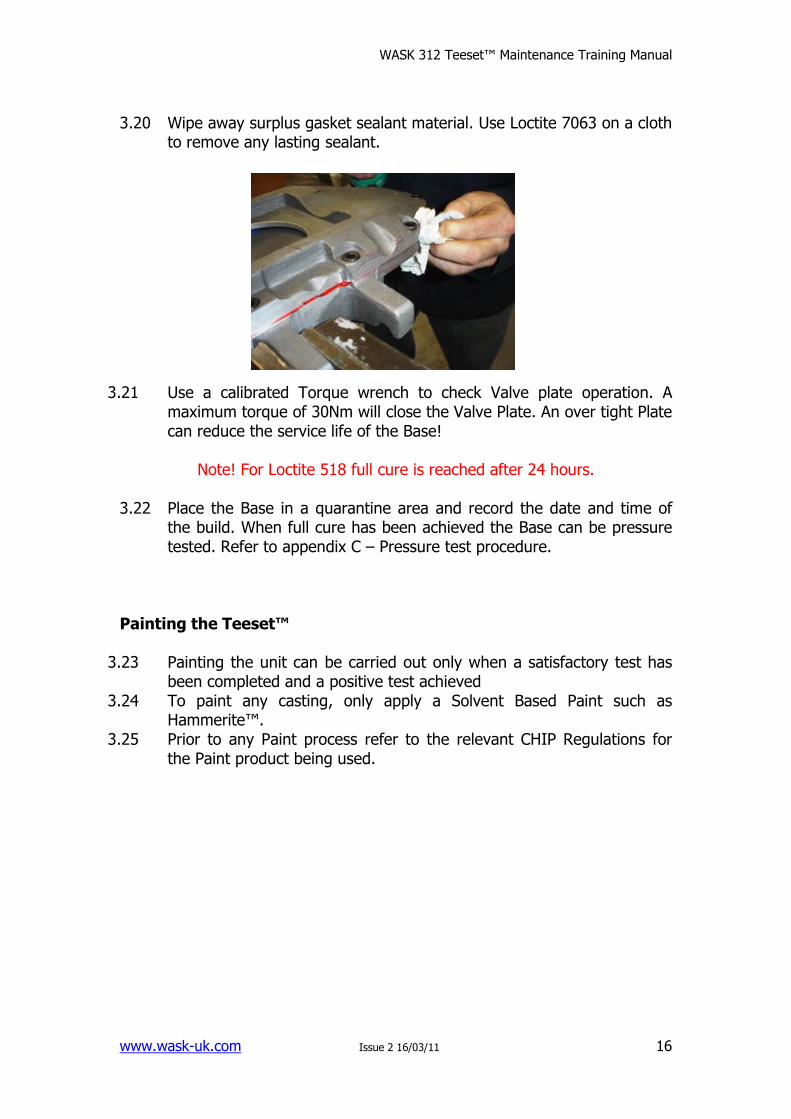
3.20 Wipe away surplus gasket sealant material. Use Loctite 7063 on a cloth to remove any lasting sealant.
3.21 Use a calibrated Torque wrench to check Valve plate operation. A
maximum torque of 30Nm will close the Valve Plate. An over tight Plate can reduce the service life of the Base!
Note! For Loctite 518 full cure is reached after 24 hours.
3.22 Place the Base in a quarantine area and record the date and time of
the build. When full cure has been achieved the Base can be pressure tested. Refer to appendix C – Pressure test procedure.
Painting the Teeset™
3.23 Painting the unit can be carried out only when a satisfactory test has been completed and a positive test achieved
3.24 To paint any casting, only apply a Solvent Based Paint such as Hammerite™.
3.25 Prior to any Paint process refer to the relevant CHIP Regulations for the Paint product being used.
WASK 312 Teeset™ Maintenance Training Manual
www.wask-uk.com Issue 2 16/03/11
17
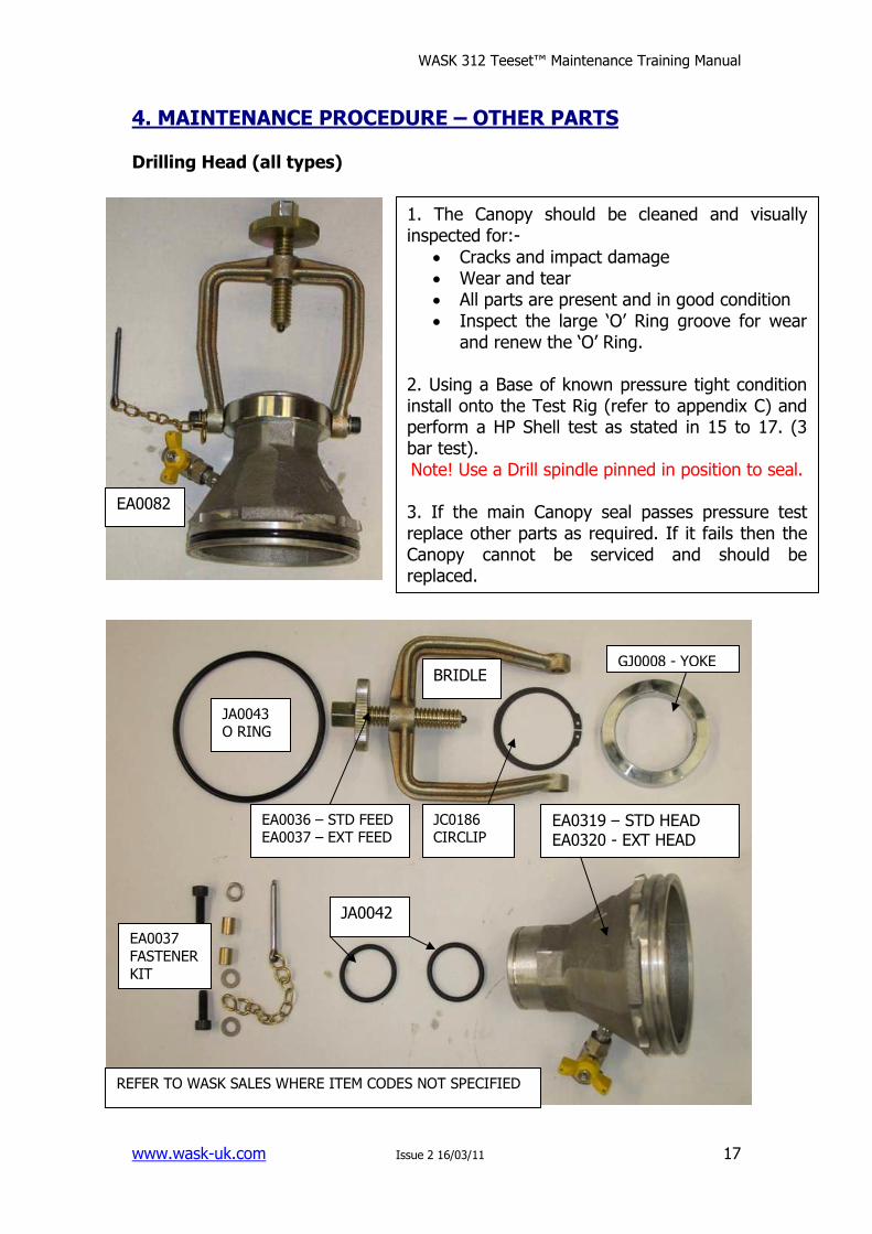
4. MAINTENANCE PROCEDURE – OTHER PARTS Drilling Head (all types)
1. The Canopy should be cleaned and visually inspected for:-
• Cracks and impact damage • Wear and tear • All parts are present and in good condition • Inspect the large ‘O’ Ring groove for wear
and renew the ‘O’ Ring. 2. Using a Base of known pressure tight condition install onto the Test Rig (refer to appendix C) and perform a HP Shell test as stated in 15 to 17. (3 bar test). Note! Use a Drill spindle pinned in position to seal. 3. If the main Canopy seal passes pressure test replace other parts as required. If it fails then the Canopy cannot be serviced and should be replaced.
JA0043 O RING
EA0037
FASTENER
KIT
JA0042
EA0319 – STD HEAD EA0320 - EXT HEAD
GJ0008 - YOKE BRIDLE
EA0036 – STD FEED EA0037 – EXT FEED
JC0186 CIRCLIP
REFER TO WASK SALES WHERE ITEM CODES NOT SPECIFIED
EA0082
WASK 312 Teeset™ Maintenance Training Manual
www.wask-uk.com Issue 2 16/03/11
18
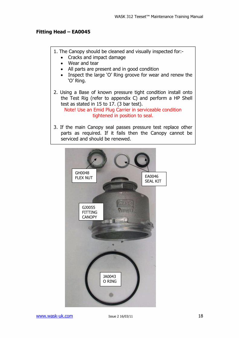
Fitting Head – EA0045
1. The Canopy should be cleaned and visually inspected for:-
• Cracks and impact damage • Wear and tear • All parts are present and in good condition
• Inspect the large ‘O’ Ring groove for wear and renew the ‘O’ Ring.
2. Using a Base of known pressure tight condition install onto
the Test Rig (refer to appendix C) and perform a HP Shell test as stated in 15 to 17. (3 bar test). Note! Use an Emid Plug Carrier in serviceable condition
tightened in position to seal. 3. If the main Canopy seal passes pressure test replace other
parts as required. If it fails then the Canopy cannot be serviced and should be renewed.
JA0043 O RING
GJ0055
FITTING CANOPY
EA0046 SEAL KIT
GH0048
FLEX NUT
WASK 312 Teeset™ Maintenance Training Manual
www.wask-uk.com Issue 2 16/03/11
19
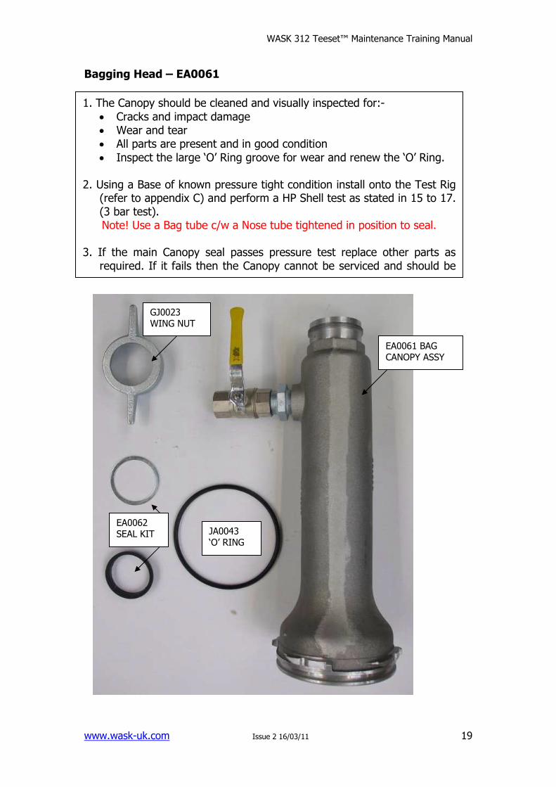
Bagging Head – EA0061
1. The Canopy should be cleaned and visually inspected for:-
• Cracks and impact damage • Wear and tear • All parts are present and in good condition
• Inspect the large ‘O’ Ring groove for wear and renew the ‘O’ Ring. 2. Using a Base of known pressure tight condition install onto the Test Rig
(refer to appendix C) and perform a HP Shell test as stated in 15 to 17. (3 bar test). Note! Use a Bag tube c/w a Nose tube tightened in position to seal.
3. If the main Canopy seal passes pressure test replace other parts as
required. If it fails then the Canopy cannot be serviced and should be renewed.
GJ0023 WING NUT
JA0043 ‘O’ RING
EA0061 BAG CANOPY ASSY
EA0062 SEAL KIT
WASK 312 Teeset™ Maintenance Training Manual
www.wask-uk.com Issue 2 16/03/11
20
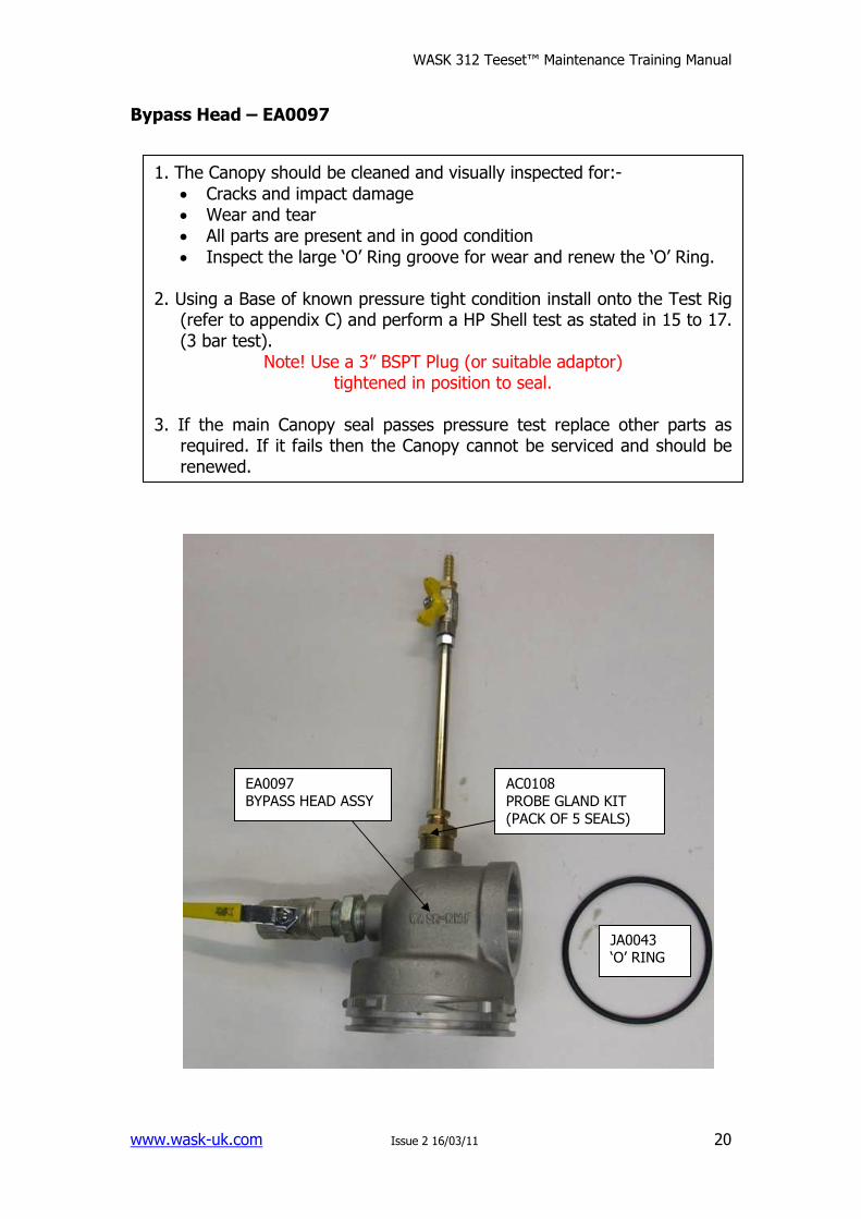
Bypass Head – EA0097
1. The Canopy should be cleaned and visually inspected for:-
• Cracks and impact damage • Wear and tear • All parts are present and in good condition
• Inspect the large ‘O’ Ring groove for wear and renew the ‘O’ Ring. 2. Using a Base of known pressure tight condition install onto the Test Rig
(refer to appendix C) and perform a HP Shell test as stated in 15 to 17. (3 bar test).
Note! Use a 3” BSPT Plug (or suitable adaptor) tightened in position to seal.
3. If the main Canopy seal passes pressure test replace other parts as
required. If it fails then the Canopy cannot be serviced and should be renewed.
JA0043 ‘O’ RING
AC0108
PROBE GLAND KIT
(PACK OF 5 SEALS)
EA0097 BYPASS HEAD ASSY
WASK 312 Teeset™ Maintenance Training Manual
www.wask-uk.com Issue 2 16/03/11
21
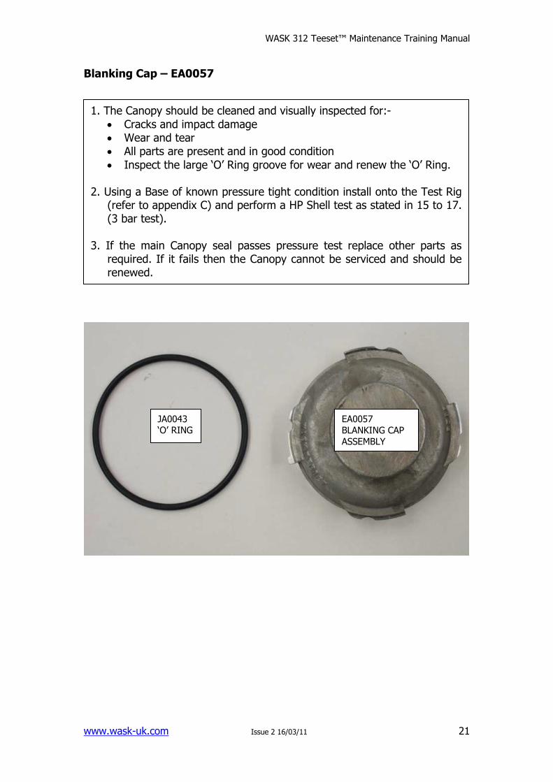
Blanking Cap – EA0057
1. The Canopy should be cleaned and visually inspected for:-
• Cracks and impact damage • Wear and tear • All parts are present and in good condition
• Inspect the large ‘O’ Ring groove for wear and renew the ‘O’ Ring. 2. Using a Base of known pressure tight condition install onto the Test Rig
(refer to appendix C) and perform a HP Shell test as stated in 15 to 17. (3 bar test).
3. If the main Canopy seal passes pressure test replace other parts as
required. If it fails then the Canopy cannot be serviced and should be renewed.
JA0043 ‘O’ RING
EA0057
BLANKING CAP
ASSEMBLY
WASK 312 Teeset™ Maintenance Training Manual
www.wask-uk.com Issue 2 16/03/11
22
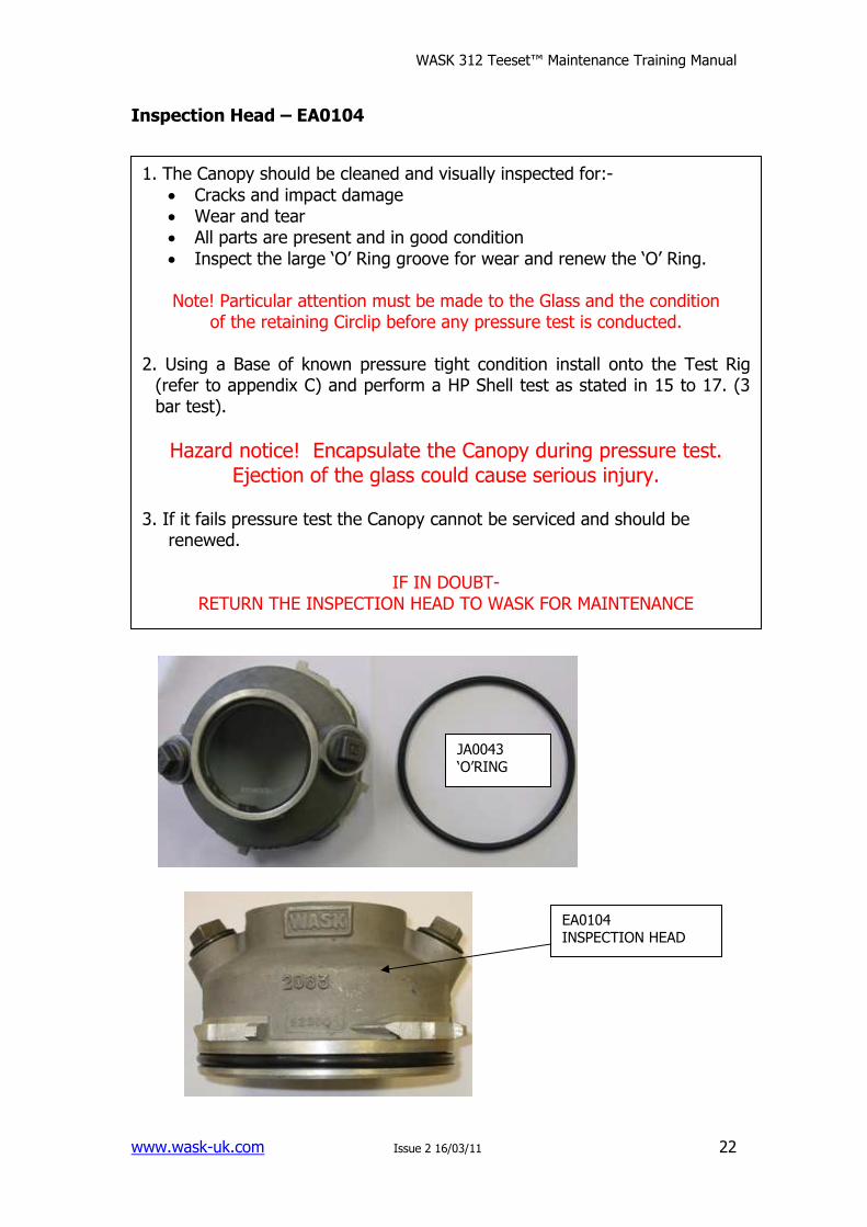
Inspection Head – EA0104
1. The Canopy should be cleaned and visually inspected for:-
• Cracks and impact damage • Wear and tear • All parts are present and in good condition
• Inspect the large ‘O’ Ring groove for wear and renew the ‘O’ Ring.
Note! Particular attention must be made to the Glass and the condition of the retaining Circlip before any pressure test is conducted.
2. Using a Base of known pressure tight condition install onto the Test Rig (refer to appendix C) and perform a HP Shell test as stated in 15 to 17. (3 bar test).
Hazard notice! Encapsulate the Canopy during pressure test. Ejection of the glass could cause serious injury.
3. If it fails pressure test the Canopy cannot be serviced and should be
renewed.
IF IN DOUBT- RETURN THE INSPECTION HEAD TO WASK FOR MAINTENANCE
EA0104 INSPECTION HEAD
JA0043 ‘O’RING
WASK 312 Teeset™ Maintenance Training Manual
www.wask-uk.com Issue 2 16/03/11
23
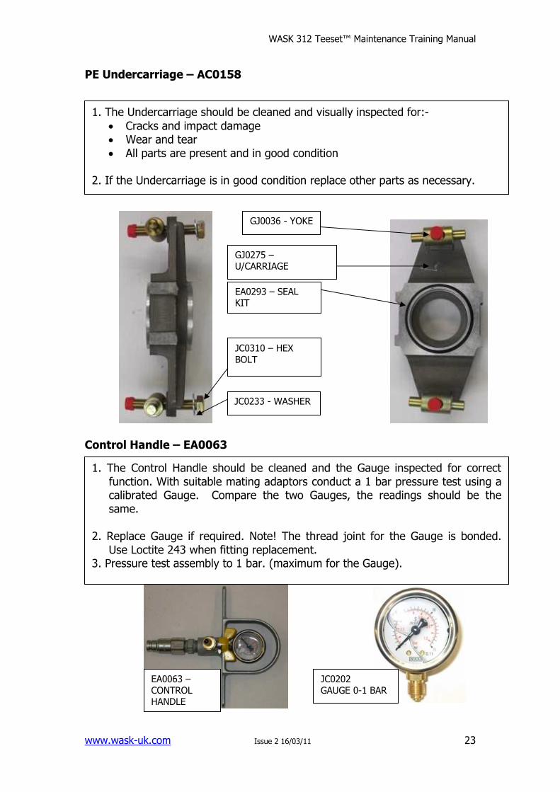
PE Undercarriage – AC0158
Control Handle – EA0063
EA0063 –
CONTROL HANDLE
JC0202
GAUGE 0-1 BAR
1. The Undercarriage should be cleaned and visually inspected for:-
• Cracks and impact damage • Wear and tear • All parts are present and in good condition
2. If the Undercarriage is in good condition replace other parts as necessary.
GJ0036 - YOKE
GJ0275 – U/CARRIAGE
EA0293 – SEAL KIT
JC0310 – HEX
BOLT
JC0233 - WASHER
1. The Control Handle should be cleaned and the Gauge inspected for correct function. With suitable mating adaptors conduct a 1 bar pressure test using a calibrated Gauge. Compare the two Gauges, the readings should be the same.
2. Replace Gauge if required. Note! The thread joint for the Gauge is bonded.
Use Loctite 243 when fitting replacement. 3. Pressure test assembly to 1 bar. (maximum for the Gauge).
WASK 312 Teeset™ Maintenance Training Manual
www.wask-uk.com Issue 2 16/03/11
24
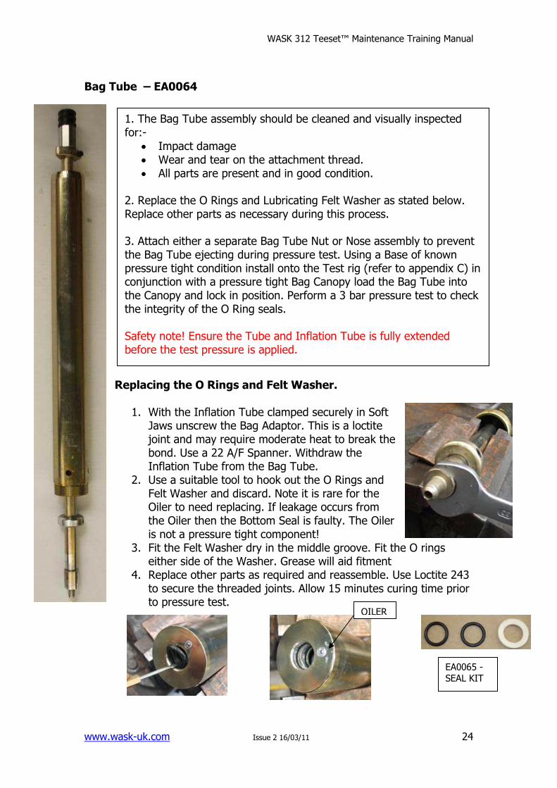
Bag Tube – EA0064 Replacing the O Rings and Felt Washer.
1. With the Inflation Tube clamped securely in Soft Jaws unscrew the Bag Adaptor. This is a loctite joint and may require moderate heat to break the bond. Use a 22 A/F Spanner. Withdraw the Inflation Tube from the Bag Tube.
2. Use a suitable tool to hook out the O Rings and Felt Washer and discard. Note it is rare for the Oiler to need replacing. If leakage occurs from the Oiler then the Bottom Seal is faulty. The Oiler is not a pressure tight component!
3. Fit the Felt Washer dry in the middle groove. Fit the O rings either side of the Washer. Grease will aid fitment
4. Replace other parts as required and reassemble. Use Loctite 243 to secure the threaded joints. Allow 15 minutes curing time prior to pressure test.
1. The Bag Tube assembly should be cleaned and visually inspected for:-
• Impact damage • Wear and tear on the attachment thread. • All parts are present and in good condition.
2. Replace the O Rings and Lubricating Felt Washer as stated below. Replace other parts as necessary during this process. 3. Attach either a separate Bag Tube Nut or Nose assembly to prevent the Bag Tube ejecting during pressure test. Using a Base of known pressure tight condition install onto the Test rig (refer to appendix C) in conjunction with a pressure tight Bag Canopy load the Bag Tube into the Canopy and lock in position. Perform a 3 bar pressure test to check the integrity of the O Ring seals. Safety note! Ensure the Tube and Inflation Tube is fully extended before the test pressure is applied.
EA0065 - SEAL KIT
OILER
WASK 312 Teeset™ Maintenance Training Manual
www.wask-uk.com Issue 2 16/03/11
25
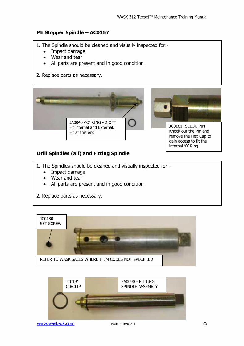
PE Stopper Spindle – AC0157
Drill Spindles (all) and Fitting Spindle
1. The Spindle should be cleaned and visually inspected for:-
• Impact damage • Wear and tear • All parts are present and in good condition
2. Replace parts as necessary.
JA0040 -‘O’ RING - 2 OFF
Fit internal and External.
Fit at this end
JC0161 -SELOK PIN
Knock out the Pin and
remove the Hex Cap to gain access to fit the internal ‘O’ Ring
1. The Spindles should be cleaned and visually inspected for:-
• Impact damage • Wear and tear • All parts are present and in good condition
2. Replace parts as necessary.
JC0180 SET SCREW
REFER TO WASK SALES WHERE ITEM CODES NOT SPECIFIED
EA0090 - FITTING SPINDLE ASSEMBLY
JC0191 CIRCLIP
WASK 312 Teeset™ Maintenance Training Manual
www.wask-uk.com Issue 2 16/03/11
26
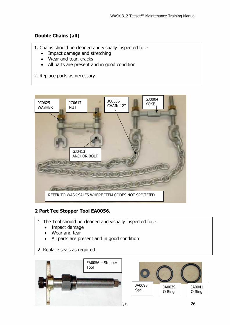
Double Chains (all)
2 Part Tee Stopper Tool EA0056.
1. Chains should be cleaned and visually inspected for:- • Impact damage and stretching
• Wear and tear, cracks • All parts are present and in good condition
2. Replace parts as necessary.
REFER TO WASK SALES WHERE ITEM CODES NOT SPECIFIED
JC0536 CHAIN 12”
JC0617 NUT
JC0625 WASHER
GJ0004 YOKE
GJ0413 ANCHOR BOLT
1. The Tool should be cleaned and visually inspected for:-
• Impact damage • Wear and tear
• All parts are present and in good condition 2. Replace seals as required.
EA0056 – Stopper Tool
JA0041 O Ring
JA0039 O Ring
JA0095 Seal
WASK 312 Teeset™ Maintenance Training Manual
www.wask-uk.com Issue 2 16/03/11
27
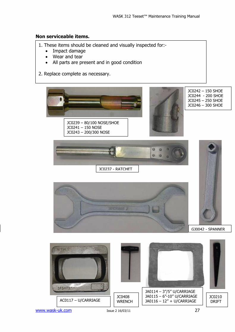
Non serviceable items.
1. These items should be cleaned and visually inspected for:- • Impact damage
• Wear and tear • All parts are present and in good condition
2. Replace complete as necessary.
JC0239 – 80/100 NOSE/SHOE JC0241 – 150 NOSE
JC0243 – 200/300 NOSE
JC0242 – 150 SHOE
JC0244 - 200 SHOE
JC0245 – 250 SHOE JC0246 – 300 SHOE
JC0237 - RATCHET
GJ0042 - SPANNER
JC0210 DRIFT
JC0408 WRENCH
JA0114 – 3”/5” U/CARRIAGE
JA0115 – 6”-10” U/CARRIAGE
JA0116 – 12” + U/CARRIAGE AC0117 – U/CARRIAGE
WASK 312 Teeset™ Maintenance Training Manual
www.wask-uk.com Issue 2 16/03/11
28
5. WASTE DISPOSAL
5.1 In all occasions, follow local waste disposal procedures.
5.2 All metallic parts to the equipment can be recycled.
5.3 All rubber based components should be disposed of and classed as general waste
WASK 312 Teeset™ Maintenance Training Manual
www.wask-uk.com Issue 2 16/03/11
29
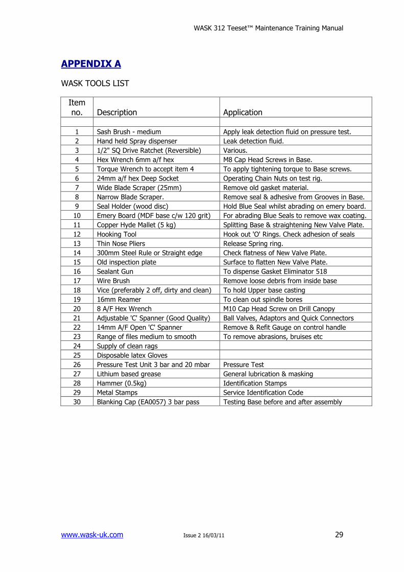
APPENDIX A
WASK TOOLS LIST
Item no. Description Application
1 Sash Brush - medium Apply leak detection fluid on pressure test.
2 Hand held Spray dispenser Leak detection fluid.
3 1/2" SQ Drive Ratchet (Reversible) Various.
4 Hex Wrench 6mm a/f hex M8 Cap Head Screws in Base.
5 Torque Wrench to accept item 4 To apply tightening torque to Base screws.
6 24mm a/f hex Deep Socket Operating Chain Nuts on test rig.
7 Wide Blade Scraper (25mm) Remove old gasket material.
8 Narrow Blade Scraper. Remove seal & adhesive from Grooves in Base.
9 Seal Holder (wood disc) Hold Blue Seal whilst abrading on emery board.
10 Emery Board (MDF base c/w 120 grit) For abrading Blue Seals to remove wax coating.
11 Copper Hyde Mallet (5 kg) Splitting Base & straightening New Valve Plate.
12 Hooking Tool Hook out 'O' Rings. Check adhesion of seals
13 Thin Nose Pliers Release Spring ring.
14 300mm Steel Rule or Straight edge Check flatness of New Valve Plate.
15 Old inspection plate Surface to flatten New Valve Plate.
16 Sealant Gun To dispense Gasket Eliminator 518
17 Wire Brush Remove loose debris from inside base
18 Vice (preferably 2 off, dirty and clean) To hold Upper base casting
19 16mm Reamer To clean out spindle bores
20 8 A/F Hex Wrench M10 Cap Head Screw on Drill Canopy
21 Adjustable 'C' Spanner (Good Quality) Ball Valves, Adaptors and Quick Connectors
22 14mm A/F Open 'C' Spanner Remove & Refit Gauge on control handle
23 Range of files medium to smooth To remove abrasions, bruises etc
24 Supply of clean rags
25 Disposable latex Gloves
26 Pressure Test Unit 3 bar and 20 mbar Pressure Test
27 Lithium based grease General lubrication & masking
28 Hammer (0.5kg) Identification Stamps
29 Metal Stamps Service Identification Code
30 Blanking Cap (EA0057) 3 bar pass Testing Base before and after assembly
WASK 312 Teeset™ Maintenance Training Manual
www.wask-uk.com Issue 2 16/03/11
30
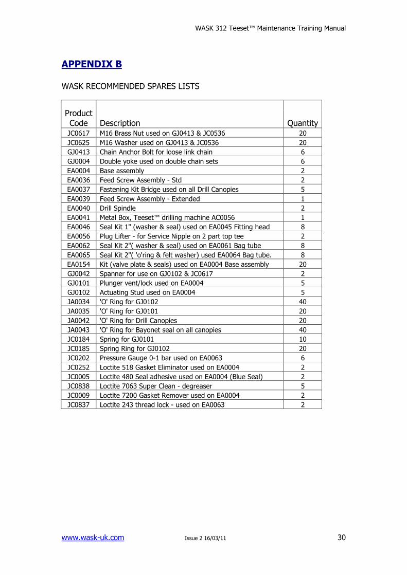
APPENDIX B
WASK RECOMMENDED SPARES LISTS
Product Code Description Quantity JC0617 M16 Brass Nut used on GJ0413 & JC0536 20
JC0625 M16 Washer used on GJ0413 & JC0536 20
GJ0413 Chain Anchor Bolt for loose link chain 6
GJ0004 Double yoke used on double chain sets 6
EA0004 Base assembly 2
EA0036 Feed Screw Assembly - Std 2
EA0037 Fastening Kit Bridge used on all Drill Canopies 5
EA0039 Feed Screw Assembly - Extended 1
EA0040 Drill Spindle 2
EA0041 Metal Box, Teeset™ drilling machine AC0056 1
EA0046 Seal Kit 1" (washer & seal) used on EA0045 Fitting head 8
EA0056 Plug Lifter - for Service Nipple on 2 part top tee 2
EA0062 Seal Kit 2"( washer & seal) used on EA0061 Bag tube 8
EA0065 Seal Kit 2"( 'o'ring & felt washer) used EA0064 Bag tube. 8
EA0154 Kit (valve plate & seals) used on EA0004 Base assembly 20
GJ0042 Spanner for use on GJ0102 & JC0617 2
GJ0101 Plunger vent/lock used on EA0004 5
GJ0102 Actuating Stud used on EA0004 5
JA0034 'O' Ring for GJ0102 40
JA0035 'O' Ring for GJ0101 20
JA0042 'O' Ring for Drill Canopies 20
JA0043 'O' Ring for Bayonet seal on all canopies 40
JC0184 Spring for GJ0101 10
JC0185 Spring Ring for GJ0102 20
JC0202 Pressure Gauge 0-1 bar used on EA0063 6
JC0252 Loctite 518 Gasket Eliminator used on EA0004 2
JC0005 Loctite 480 Seal adhesive used on EA0004 (Blue Seal) 2
JC0838 Loctite 7063 Super Clean - degreaser 5
JC0009 Loctite 7200 Gasket Remover used on EA0004 2
JC0837 Loctite 243 thread lock - used on EA0063 2
WASK 312 Teeset™ Maintenance Training Manual
www.wask-uk.com Issue 2 16/03/11
31
APPENDIX C
Pressure test procedure for the Tee set Base.
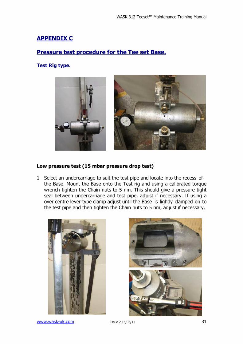
Test Rig type. Low pressure test (15 mbar pressure drop test) 1 Select an undercarriage to suit the test pipe and locate into the recess of
the Base. Mount the Base onto the Test rig and using a calibrated torque wrench tighten the Chain nuts to 5 nm. This should give a pressure tight seal between undercarriage and test pipe, adjust if necessary. If using a over centre lever type clamp adjust until the Base is lightly clamped on to the test pipe and then tighten the Chain nuts to 5 nm, adjust if necessary.
WASK 312 Teeset™ Maintenance Training Manual
www.wask-uk.com Issue 2 16/03/11
32
Low pressure test procedure continued. 2 Ensure that the HP input is isolated and that the LP side is open. Sweep
the valve plate to complete one cycle from open to the closed position. The valve plate must be dry and free of any lubricant other than that provided by the valve plate coating.
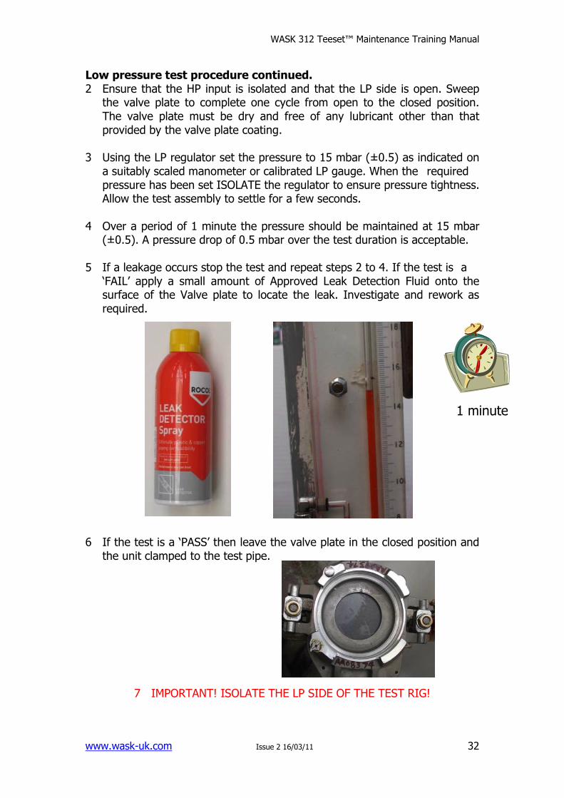
3 Using the LP regulator set the pressure to 15 mbar (±0.5) as indicated on
a suitably scaled manometer or calibrated LP gauge. When the required pressure has been set ISOLATE the regulator to ensure pressure tightness. Allow the test assembly to settle for a few seconds.
4 Over a period of 1 minute the pressure should be maintained at 15 mbar
(±0.5). A pressure drop of 0.5 mbar over the test duration is acceptable. 5 If a leakage occurs stop the test and repeat steps 2 to 4. If the test is a
‘FAIL’ apply a small amount of Approved Leak Detection Fluid onto the surface of the Valve plate to locate the leak. Investigate and rework as required.
6 If the test is a ‘PASS’ then leave the valve plate in the closed position and
the unit clamped to the test pipe.
7 IMPORTANT! ISOLATE THE LP SIDE OF THE TEST RIG!
1 minute
WASK 312 Teeset™ Maintenance Training Manual
www.wask-uk.com Issue 2 16/03/11
33
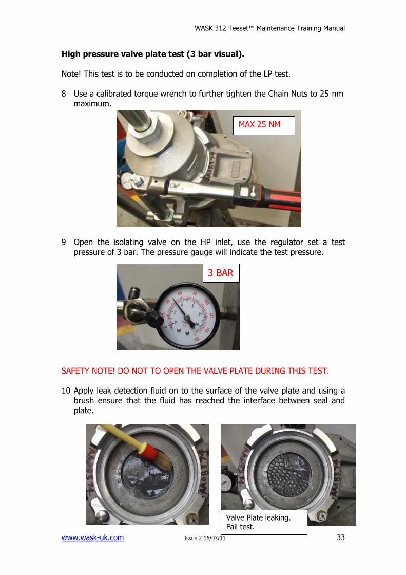
High pressure valve plate test (3 bar visual). Note! This test is to be conducted on completion of the LP test. 8 Use a calibrated torque wrench to further tighten the Chain Nuts to 25 nm
maximum. 9 Open the isolating valve on the HP inlet, use the regulator set a test
pressure of 3 bar. The pressure gauge will indicate the test pressure. SAFETY NOTE! DO NOT TO OPEN THE VALVE PLATE DURING THIS TEST. 10 Apply leak detection fluid on to the surface of the valve plate and using a
brush ensure that the fluid has reached the interface between seal and plate.
MAX 25 NM
3 BAR
Valve Plate leaking. Fail test.
WASK 312 Teeset™ Maintenance Training Manual
www.wask-uk.com Issue 2 16/03/11
34
High pressure valve plate test (3 bar visual). 11 Check for air bubbles around the perimeter of the valve plate seal. 12 If there is leakage then depressurize the test assembly by using a
separate dump valve if fitted or via the venting regulator. The pressure gauge should indicate zero pressure.
13 Cycle the valve plate from the closed position to open and back to closed
and repeat steps 1 to 3. If the test result is ‘FAIL’ depressurize, investigate and rework as required.
14 If the test is a ‘PASS’ then depressurize and leave the valve plate in the
open position.
SAFETY NOTE! BEFORE ATTEMPTING TO OPEN THE VALVE PLATE ENSURE THAT THE TEST ASSEMBLY HAS DEPRESSURISED.
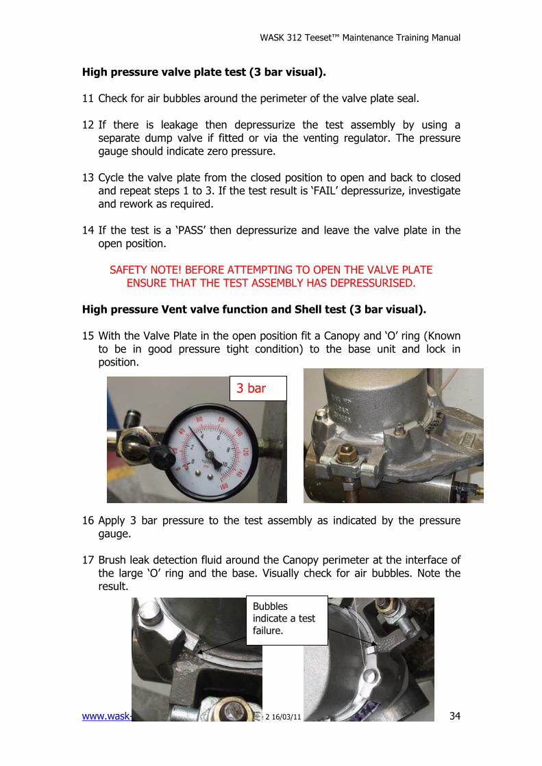
High pressure Vent valve function and Shell test (3 bar visual). 15 With the Valve Plate in the open position fit a Canopy and ‘O’ ring (Known
to be in good pressure tight condition) to the base unit and lock in position.
16 Apply 3 bar pressure to the test assembly as indicated by the pressure
gauge. 17 Brush leak detection fluid around the Canopy perimeter at the interface of
the large ‘O’ ring and the base. Visually check for air bubbles. Note the result.
3 bar
Bubbles indicate a test
failure.
WASK 312 Teeset™ Maintenance Training Manual
www.wask-uk.com Issue 2 16/03/11
35
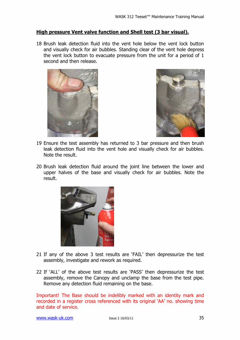
High pressure Vent valve function and Shell test (3 bar visual). 18 Brush leak detection fluid into the vent hole below the vent lock button
and visually check for air bubbles. Standing clear of the vent hole depress the vent lock button to evacuate pressure from the unit for a period of 1 second and then release.
19 Ensure the test assembly has returned to 3 bar pressure and then brush
leak detection fluid into the vent hole and visually check for air bubbles. Note the result.
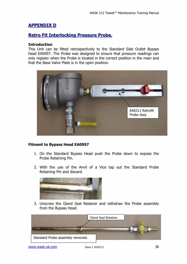
20 Brush leak detection fluid around the joint line between the lower and
upper halves of the base and visually check for air bubbles. Note the result.
21 If any of the above 3 test results are ‘FAIL’ then depressurize the test
assembly, investigate and rework as required. 22 If ‘ALL’ of the above test results are ‘PASS’ then depressurize the test
assembly, remove the Canopy and unclamp the base from the test pipe. Remove any detection fluid remaining on the base.
Important! The Base should be indelibly marked with an identity mark and recorded in a register cross referenced with its original ‘AA’ no. showing time and date of service.
WASK 312 Teeset™ Maintenance Training Manual
www.wask-uk.com Issue 2 16/03/11
36
APPENDIX D
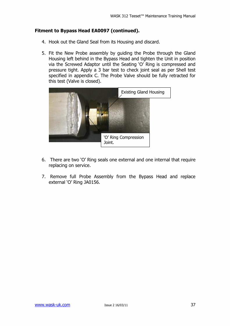
Retro Fit Interlocking Pressure Probe. Introduction This Unit can be fitted retrospectively to the Standard Side Outlet Bypass head EA0097. The Probe was designed to ensure that pressure readings can only register when the Probe is located in the correct position in the main and that the Base Valve Plate is in the open position. Fitment to Bypass Head EA0097
1. On the Standard Bypass Head push the Probe down to expose the Probe Retaining Pin.
2. With the use of the Anvil of a Vice tap out the Standard Probe
Retaining Pin and discard.
3. Unscrew the Gland Seal Retainer and withdraw the Probe assembly from the Bypass Head.
Gland Seal Retainer.
Standard Probe assembly removed.
EA0311 Retrofit Probe Assy
WASK 312 Teeset™ Maintenance Training Manual
www.wask-uk.com Issue 2 16/03/11
37
Fitment to Bypass Head EA0097 (continued).
4. Hook out the Gland Seal from its Housing and discard.
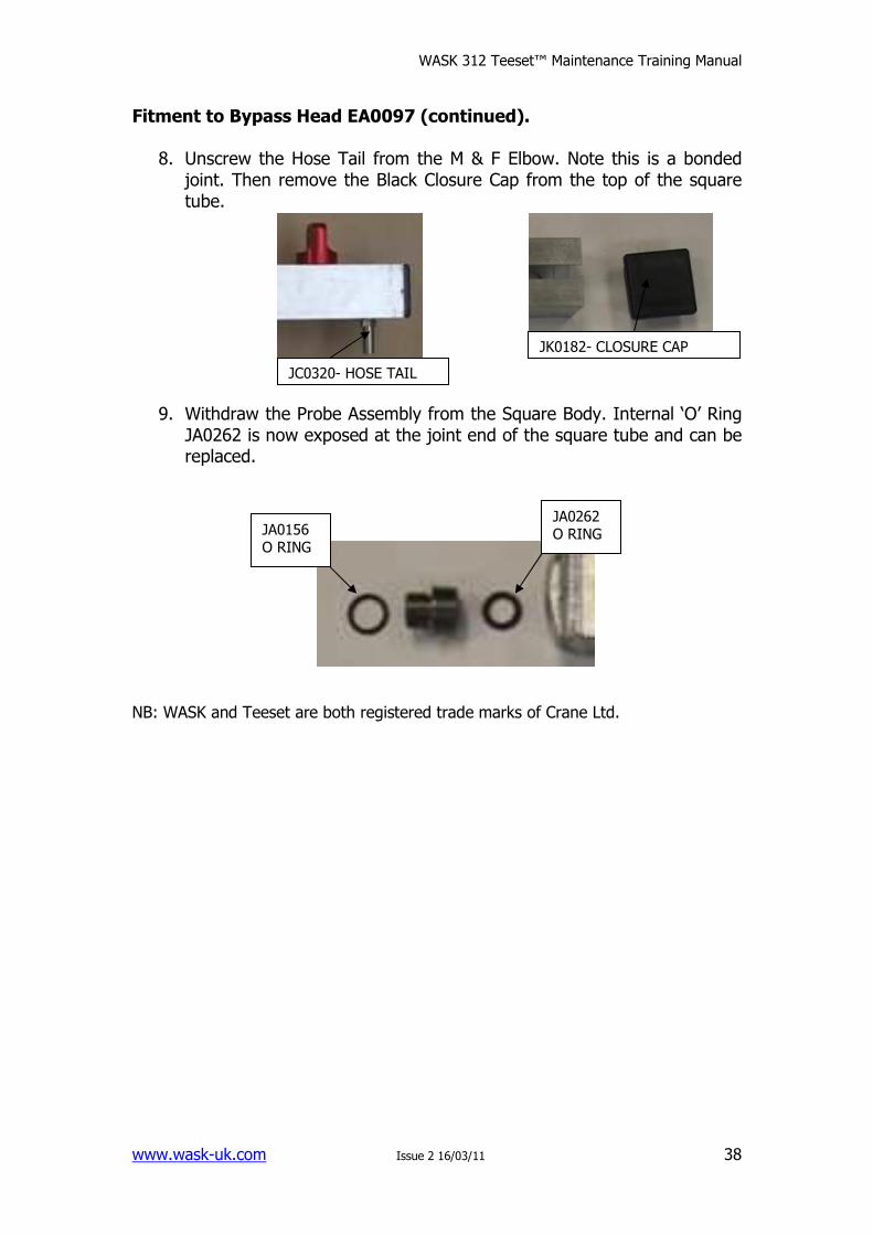
5. Fit the New Probe assembly by guiding the Probe through the Gland Housing left behind in the Bypass Head and tighten the Unit in position via the Screwed Adaptor until the Seating ‘O’ Ring is compressed and pressure tight. Apply a 3 bar test to check joint seal as per Shell test specified in appendix C. The Probe Valve should be fully retracted for this test (Valve is closed).
6. There are two ‘O’ Ring seals one external and one internal that require replacing on service.
7. Remove full Probe Assembly from the Bypass Head and replace
external ‘O’ Ring JA0156.
Existing Gland Housing
‘O’ Ring Compression Joint.
WASK 312 Teeset™ Maintenance Training Manual
www.wask-uk.com Issue 2 16/03/11
38
Fitment to Bypass Head EA0097 (continued).
8. Unscrew the Hose Tail from the M & F Elbow. Note this is a bonded joint. Then remove the Black Closure Cap from the top of the square tube.
9. Withdraw the Probe Assembly from the Square Body. Internal ‘O’ Ring JA0262 is now exposed at the joint end of the square tube and can be replaced.
NB: WASK and Teeset are both registered trade marks of Crane Ltd.
JA0156 O RING
JA0262 O RING
JK0182- CLOSURE CAP
JC0320- HOSE TAIL

DELTA ROAD,ST HELENS, WA9 2ED
TELEPHONE: +44 (0)1744 458649FAX: +44 (0)1744 453675EMAIL: [email protected]
www.wask-uk.com
• Designed & manufactured under quality managementsystems in accordance with BS EN ISO 9001:2008
Every effort has been made to ensure that the information contained in thispublication is accurate at the time of publishing. Crane Ltd assumes no responsibilityor liability for typographical errors or omissions or for any misinterpretation of theinformation within the publication & reserves the right to change without notice.
FM311ISO 9001
www.cranebsu.com
W_3
12_0
411
IOM
_JR
0079
Visitwww.flowoffluids.comto book your copy of theNew Technical Paper 410.