Embed Size (px)
Citation preview

Eaton Aerospace Group Fluid & Electrical Distribution Division Carter
®
Ground Fueling Equipment
SM60427
May 2013
Supersedes release February 2013
Applicable additional manuals:
SM40679 SM60129-1 SM60672-1 SM61154 SM427MIS SM64001 SM64015
Maintenance & Repair Manual
Underwing Refueling Nozzle
Model 60427

TABLE OF CONTENTS
Page
1.0 Introduction ............................................................................................... 3
2.0 Equipment Description ............................................................................. 3
3.0 Table of Options & Ordering Information ................................................. 3
4.0 Safety Instructions .................................................................................... 5
5.0 Special Tools ............................................................................................ 8
6.0 Disassembly ............................................................................................. 8
7.0 Inspection ................................................................................................. 9
8.0 Reassembly .............................................................................................. 9
9.0 Test .......................................................................................................... 11
10.0 Illustrated Parts Catalog .......................................................................... 11
Figure 1 ............................................................................................................ 15
Figure 2 ............................................................................................................ 16
Figure 3 ............................................................................................................ 17
Figure 4 ............................................................................................................ 18
Figure 6 ............................................................................................................ 19
11.0 Failure Modes And Effects Analysis – Nozzle ......................................... 20
12.0 Failure Modes And Effects Analysis – Hose End Control Valve.............. 24

SM60427 May 2013
3
Maintenance, Overhaul & Test Instructions
Carter® Model 60427
Underwing Refueling Nozzle
1.0 INTRODUCTION
This manual furnishes detailed instructions covering the maintenance and overhaul of Eaton’s Carter ground fueling equipment product line Model 60427 Underwing Refueling Nozzle and its various options. For the maintenance of options to the basic 60427 nozzle, refer to Options Table, Section 3.0. This table will reference the service manual that should be used in the maintenance of each option.
In this latest issue, the new part numbering system required to identify the nozzle is also fully explained. (See Section 3.0).
Model 60427 nozzle is designed to mate all international standard aircraft adapters made in accordance with MS24484, MS29514 or equivalent.
2.0 EQUIPMENT DESCRIPTION
Model 60427 nozzle is a 2-1/2 inch underwing refueling nozzle. It is designed for use with all grades of commercial and military jet fuels. Its operating pressure range is 0 - 200 psi with a rated flow of 600 gpm. The nozzle will have a pressure drop of approximately 3 psi at rated flow when fully opened. The operating temperature range is -35° F to 150° F (-37° C to 66° C). The basic nozzle would be procured as
model number 60427, which would include the standard handle grips and nose seal. Other options that are available to build a nozzle to specific specifications are listed in the table shown in Section 3.0. The exploded view, figure 2, includes options D, E & T. Other available options are either shown in the other exploded views or in the separate manuals referenced as accessory to this manual.
3.0 TABLE OF OPTIONS & ORDERING INFORMATION
The basic Model 60427 is available with a variety of options to customize it to meet specific requirements as listed in the table below. The various options, when compatible,
may be combined and listed following the model number 60427 to achieve a complete unit. The model number of a complete nozzle consists of four basic parts as illustrated below.
PART 1 – Model Number
60427
PART 4 – Letter describing the inlet thread size & type
PART 3 – Number describing the male adapter required to mate the desired inlet
configuration
PART 2 – Options B-Z describing various changes to the basic configuration
SM60427 May 2013
4
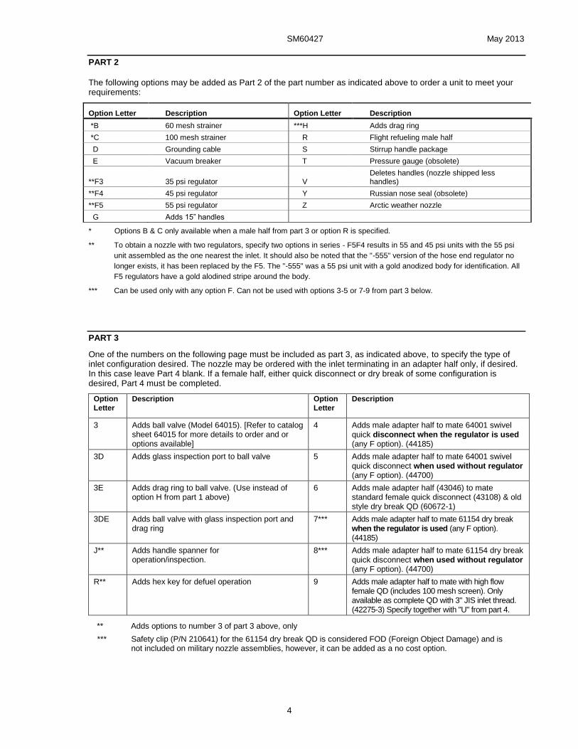
PART 2
The following options may be added as Part 2 of the part number as indicated above to order a unit to meet your requirements:
Option Letter Description Option Letter Description
*B 60 mesh strainer ***H Adds drag ring
*C 100 mesh strainer R Flight refueling male half
D Grounding cable S Stirrup handle package
E Vacuum breaker T Pressure gauge (obsolete)
**F3 35 psi regulator V Deletes handles (nozzle shipped less handles)
**F4 45 psi regulator Y Russian nose seal (obsolete)
**F5 55 psi regulator Z Arctic weather nozzle
G Adds 15” handles
* Options B & C only available when a male half from part 3 or option R is specified.
** To obtain a nozzle with two regulators, specify two options in series - F5F4 results in 55 and 45 psi units with the 55 psi
unit assembled as the one nearest the inlet. It should also be noted that the "-555" version of the hose end regulator no
longer exists, it has been replaced by the F5. The "-555" was a 55 psi unit with a gold anodized body for identification. All
F5 regulators have a gold alodined stripe around the body.
*** Can be used only with any option F. Can not be used with options 3-5 or 7-9 from part 3 below.
PART 3
One of the numbers on the following page must be included as part 3, as indicated above, to specify the type of inlet configuration desired. The nozzle may be ordered with the inlet terminating in an adapter half only, if desired. In this case leave Part 4 blank. If a female half, either quick disconnect or dry break of some configuration is desired, Part 4 must be completed.
Option
Letter
Description Option
Letter
Description
3 Adds ball valve (Model 64015). [Refer to catalog sheet 64015 for more details to order and or options available]
4 Adds male adapter half to mate 64001 swivel quick disconnect when the regulator is used (any F option). (44185)
3D Adds glass inspection port to ball valve 5 Adds male adapter half to mate 64001 swivel quick disconnect when used without regulator (any F option). (44700)
3E Adds drag ring to ball valve. (Use instead of option H from part 1 above)
6 Adds male adapter half (43046) to mate standard female quick disconnect (43108) & old style dry break QD (60672-1)
3DE Adds ball valve with glass inspection port and drag ring
7*** Adds male adapter half to mate 61154 dry break when the regulator is used (any F option). (44185)
J** Adds handle spanner for operation/inspection.
8*** Adds male adapter half to mate 61154 dry break quick disconnect when used without regulator (any F option). (44700)
R** Adds hex key for defuel operation 9 Adds male adapter half to mate with high flow female QD (includes 100 mesh screen). Only available as complete QD with 3" JIS inlet thread. (42275-3) Specify together with "U" from part 4.
** Adds options to number 3 of part 3 above, only
*** Safety clip (P/N 210641) for the 61154 dry break QD is considered FOD (Foreign Object Damage) and is not included on military nozzle assemblies, however, it can be added as a no cost option.

SM60427 May 2013
5
PART 4
One of the following letters must be included as Part 4 as indicated above to specify the inlet thread and size:
Option
Letter Description
Option
Letter Description
H Inlet thread - 2½" NPT N Inlet thread - 2" BSPP
K Inlet thread - 2½" BSPP P Inlet thread - 2" NPT
L Inlet thread - 3" NPT U Inlet thread - 3" JIS (only available with option 9
from part 3 only)
*M Inlet thread - 3" BSPP Z Inlet thread - 3" JIS (only available with option 6
from part 3 only)
* Not available with ball valve, option 3 from part 3 above.
Examples: 60427BDF36H - Nozzle with 60 mesh screen, grounding cable, 35 psi regulator and 2 1/2 NPT 40679-1 QD.
60427CF5F57K - Nozzle with 100 mesh screen, two 55 psi regulators and 2 1/2 BSPP 61154JK dry break QD.
60427C8K - Nozzle with 100 mesh screen and 2 1/2 BSPP 61154DK dry break. The following table should be used to determine the service manual to be used in the maintenance, repair or replacement of parts designated by option letters to the basic 60427 nozzle.
Option
Letter Part Number Service Manual
Option
Letter Part Number Service Manual
B 41767-60 SM40679 4 44185 SM64001
C 41767-100 SM40679 4H, K-P 64001H, K-P SM64001
D 41768 SM60427 5 44700 SM64001
E 41599 SM60427 5H, K-P 64001H, K-P SM64001
F* 60129-1* SM60129-1 6 43046 SM40679
G 43003-2 SM60427 6H, K-P & Z 40679- SM40679
R 41600 SM427MISC 7 44185 SM61154
S 43003-3 SM60427 7H, K-P 61154H, K-P SM61154
T** 41770 SM60427 8 44700 SM61154
Y** 29649 & 29650 SM60427 8H, K-P 61154H, K-P SM61154
Z 47101 SM60427 9U 42275-3 SM42275
3H, K, L, N, P 64015 SM64015
* Three different regulators are available. Refer to the following pages regarding part numbering for more details.
** Option T pressure gauge and option Y, Russian nose seal, available only as long as inventory of the parts is available. Nozzles with the old style dry break Model 60672-1 were sold under options TT through YY to the basic nozzle. Model 60672-1 is out of production and has been superseded by Model 61154 dry break quick disconnect. The male and female halves of the 61154 are not interchangeable with either the 60672-1 series male and female halves. The entire dry break disconnect must be replaced. The male half adapter, 43046, is still available as a spare part. However, if the female half is required as a replacement for a 60672-1, a complete 61154 (appropriate options specified) will have to be ordered.
4.0 SAFETY INSTRUCTIONS
There are several safety interlock features designed into the Model 60427 nozzle that must be functioning to prevent an accident that would result in a spill of flammable liquids with the
consequential risk of fire, personal injury or death, and property damage. Refer to Table 1.0, Section 10.0, to identify individual parts during the following discussion.
4.1 COLLAR ASSY LOCK AND INDEX PINS
Examination of the connection end of a disengaged nozzle not connected to an adapter discloses the three Collar Lock Pins (15) and three Index Pins (17) installed between the
Collar (9) and the Nose Seal (12) or (12A). The three spring loaded Collar Lock Pins (15) engage three cutouts (arched shaped windows) in the flange of the Collar (9) when the Collar is in the fully disengaged position. These Collar

SM60427 May 2013
6
Lock Pins (15) prevent accidental rotation of the Collar of the disengaged nozzle. One of the three cutouts in Collar (9) is normally elongated more than the other two.
With the Collar (9) locked in the disengaged position, the flat portion of a ramp integral to the Collar (9) is positioned over a flat on the Crank Handle (21) or (21A) in a manner that prevents opening the Poppet (11 or 11A).
When connecting to an aircraft, the three Index Pins (17) mate with three slots in a serviceable MS24484 Adapter Flange to index the nozzle to the flange so the Collar (9) mates with the flange lugs during engagement and prevents disengagement of the Collar (9) from the flange without releasing the three spring loaded Collar Lock Pins (15) to the Collar (9) lock positions.
4.2 CRANK HANDLE/COLLAR INTERLOCK AND OVER CENTER LINKAGE
Examination of the center portion of the Crank Handle (21) or (21A) on a disengaged nozzle discloses the fact that a flat edge of the Crank Handle (21) or (21A) is beneath the flat portion of a ramp that is integral to the Collar (9). With the Collar (9) locked by the Collar Lock Pins (15), the Collar (9) ramp prevents rotation of the Crank Handle (21) or (21A) to the poppet open position.
When the Collar (9) is fully engaged to a serviceable MS24484 Adapter the Collar ramp clears the Crank Handle (21) or (21A) and permits rotation to the open position.
With the Crank Handle (21) or (21A) fully open, the round portion of the Crank Handle (21) or (21A) prevents rotation of the Collar (9) in the disengage direction until the Crank Handle (21) or (21A) has been fully closed.
These interlocks are designed to prevent accidental opening of the poppet while disengaged, or accidentally disengaging a nozzle with the poppet open.
The poppet operating internal linkage design is such that the linkage is "over center" at each extreme of travel for Crank Handle (21) or (21A) to fully open against internal mechanical stop or to fully closed against internal mechanical stop.
Thus, internal pressure against a closed poppet, when the linkage is against the closed mechanical stop, provides a force only in the closed direction.
In a similar manner, with the Crank Handle (21) or (21A) in the fully open/mechanical stop position, the 50 lb. force applied by the MS24484 Adapter Poppet Spring provides a force to maintain the open direction.
4.3 SAFETY INSPECTIONS
The frequencies recommended for the following inspections are our recommendations based on nozzles that have been in daily service for at least a year. The frequency that is required will depend upon the degree of maintenance extended to the equipment and to the age of the equipment. It is not possible for Eaton to recommend other than the safest possible frequencies.
4.3.1 NOZZLE INSPECTIONS - AT EACH REFUELING OPERATION
The following inspections of the nozzle are recommended at each refueling operation:
A. Inspect the connection end and verify that the Index Pins (17) are intact, in place, and not excessively worn or damaged. Verify that all three Collar Lock Pins (15) are intact,
undamaged and are extended to engage all
three cutouts in the Collar (9) and physically
prevent Collar (9) rotation.
This inspection can be accomplished without interruption of the normal operating procedure and without adding appreciably to the operation time by training the operator to automatically observe the connection end of the nozzle upon disconnection from the aircraft. If the Collar Lock Pins (15) are not extended and engaged in all three cutouts in the Collar (9), the operator should squeeze the Crank Handle (21) or (21A) and Handle (6), (6A) or (6B) together while observing the connecting end of the nozzle. This should cause the Collar Lock Pins (15) to "spring" into the cutouts in the Collar (9). If not, then the nozzle should be taken out of service. If the Collar Lock Pins (15) do not spring into their correct position, it could mean that the aircraft adapter is defective and should be inspected (see paragraph 4.3.3) and reported as possibly being defective.
B. Upon engagement to an aircraft and opening the nozzle, but before operating the deadman control, it is recommended that the operator attempt to remove the nozzle from the aircraft. This should not be possible. If it can be removed, either the nozzle was never fully engaged onto the aircraft or needs repair, or the aircraft adapter, is in need of repair.
4.3.2 NOZZLES INSPECTIONS - MONTHLY BASIS
The following inspections of the nozzle are recommended to be conducted on a monthly basis as a minimum:
A. Inspect the connection end and verify that the three Index Pins (17) are intact and in place. Verify that the three Collar Lock Pins (15) are intact and in place and extended and engaging all three cutouts in the Collar (9) and physically preventing Collar (9) rotation. Check the Bearing Plate (14) containing the pins for possible cracks.

SM60427 May 2013
7
B. Hold the nozzle with the outlet or connecting end facing such that it can be observed. Apply pressure on the Collar (9) in the direction to connect the nozzle to an aircraft, counter-clockwise, to take up the slack and inspect the relative location of the three Lock Pins (15) with respect to the cutouts in the Collar (9). The two Lock Pins (15) that are engaged in the normally narrower cutouts should be resting against the edge of their respective cutouts. If there is a space between the third Lock Pin (15) and the edge of the normally larger cutout, the collar is still in functional condition. If all three Lock Pins (15) are resting against the edge of their respective cutouts (there is no space), the Collar (9) may no longer be in a functional condition and should be replaced if it fails the next step of the inspection.
C. With the nozzle being held in the position described above, attempt to open the nozzle with the Crank Handle (21) or (21A). The nozzle should be prevented from opening by the interference between the Collar (9) and the Crank Handle (21) or (21A). If the nozzle can be opened, it should be removed from service and repaired.
D. Inspect the Crank Handle (21) or (21A) and the adjacent ramp surface of the Collar (9) and verify that neither part is damaged or has missing pieces that permit the Crank Handle (21) or (21A) to be rotated to the open position with the nozzle disengaged or that will allow the Collar (9) to rotate to the disengaged position when the Crank Handle (21) or (21A) is open. Broken or missing parts can result in dangerous fuel spills while refueling aircraft.
E. Verify that the Crank Handle (21) or (21A) is in the fully closed position (against internal mechanical stop). This is necessary to assure that the linkage is over center so internal pressure can not force the poppet open during the Collar (9) engagement.
4.3.3 AIRCRAFT ADAPTER INSPECTIONS
The following inspections of the aircraft adapter are recommended to be carried out at each refueling operation to assure that one is connecting to a safe adapter:
A. Visually check for bent, broken, missing or excessively worn lugs or slots. Worn slots are easily detected. A normal slot will have a slight machine broken edge (chamfer of .030 inch (0.762 mm)). If the edge is worn such that the corner is badly distorted and enlarged it should be inspected more closely and accurately. Adapter Wear Gauge, 61657-2, should be utilized to check the width and thickness of the lugs if they appear to be worn. Wear of the thickness dimension of the lug will promote premature nose seal leakage. Wear of the width
of the lug combines with slot wear in defeating the nozzle interlock.
B. Visually check the three slots for excessive wear. Excessive wear can permit disengagement of a nozzle without release of the three Collar Lock Pins (15) and may permit accidental poppet opening on the disconnected nozzle. The use of Wear Gauge 61657-2 will provide a "no-go" check for the slots.
C. If any of the above conditions are observed, and or the gauge proves the adapter to be defective, the refueling operation should be continued only with extreme caution. The nozzle, upon disconnection, should be checked in accordance with paragraph 4.3.1.A.
4.3.4 POPPET-SHAFT RETENTION INSPECTION
This inspection procedure must be
conducted following the removal and
reinstallation of the Poppet (11 or 11A) from
the Shaft (38).
Using Eaton’s Carter brand part number S204451 three lug adapter flange (or any standard flange that is a separate loose part and not a part of some other adapter housing) open the nozzle being careful to drain all trapped fluid into a suitable container. Even if the ball valve or a dry-break disconnect is utilized, there will be a small quantity of trapped fuel in the nozzle.
Check to see if there is a Cotter Pin (10) installed through the slotted poppet and the hole in the shaft. The pin must be installed in the hole that is completely within the slotted area of the poppet and the hole that allows for proper poppet nose seal adjustment
Older nozzles will have a Cotter Pin (10) that has an overall length of approximately 1.05 inches (26.7 mm). The pin on the newer nozzles will be approximately 1.35 inches (34.3 mm) long. If the new longer Cotter Pin (10), part number GF24665-302, is available it is recommended that the existing pin be removed and the new Cotter Pin (10) installed in accordance with Figure 6. If the new pin is not available, it is recommended that the Cotter Pin (10) be checked to assure that the longer leg is bent into a partially circular loop such that the loop is as close to the shaft as possible. The shorter leg should be bent to an angle as close to 90° as possible.
Grasp the Poppet (11 or 11A) with one hand and holding the nozzle with the other attempt to un-screw the (11 or 11A) from the Shaft (38). The poppet will move a slight amount taking up the slack between the slot in the (11 or 11A), the hole in the Shaft (38) and the Cotter Pin (10).
If all is correct close the nozzle and remove the adapter flange. Put the nozzle back in service.
SM60427 May 2013
8
5.0 SPECIAL TOOLS
The following special tools are recommended for proper repair and or overhaul of the nozzle:
6958CG or 6958CH adapter or equivalent.
61657-2 adapter wear gauge
64000 poppet adjustment gauge
The above items are available from your Eaton Carter brand distributor.
6.0 DISASSEMBLY
6.1 Remove nozzle from end of hose at quick disconnect. Refer to the appropriate service manual depending upon type of swivel disconnect utilized.
SM40679 Standard 60427 nozzle disconnect
SM42275 High flow disconnect (JIS thread only)
SM427MISC Miscellaneous male half adapters not associated with a complete disconnect
SM60129-1 Hose end control valve (HECV)
SM60672-1 Old style dry break disconnect
SM61154 New style dry break disconnect
SM64015 Ball valve
If Drag Ring, option H, is present it is sandwiched between the male and female halves of the disconnect. Set aside for later inspection.
6.2 Remove the cover assembly (1) from nozzle. Before proceeding further it is recommended that the inspections detailed in paragraph 4.3.2 be conducted to get an overall picture of the condition of the nozzle. Take special note of the wear check of the Collar (9) detailed in 4.3.2.B. If all three cutouts of the Collar (9) are touching the Lock Pins (15), the Collar (9) should be replaced during overhaul.
If the Handles (6), (6A) or (6B) are to be replaced, remove hardware items (2, 4 & 5). If they do not need replacing, remove only the that Handle (6), (6A) or (6B) that is farthest away from the Crank Handle (21) to allow the indexing lug on the Body (39) to pass through the slot in the Collar (9). On later models, the regular stick type Handles (6 or 6A) are an assembly with replaceable Grips (6C) held in place with Screw (6E) and Washer (6D). Remove Grip (6C) from Handle (6F or G) only if it is necessary to replace it.
6.3 Using a sharp knife, cut the Bumper (7) to remove it from the Collar (9).
6.4 Push at one end of the collar Bearing (8) to cause the other end to protrude from groove. Using pliers, pull the collar bearing out of groove. On parts where the Bearing (8) is difficult to remove it is suggested that the outlet end of the nozzle be soaked in light motor oil over night to assist in removing it.
NOTE: Do not engage nozzle onto an adapter. This will create a load on Bearing (8).
6.5 Remove nozzle Collar (9) from Body (39) by aligning the groove in the Collar (9) with square boss on the side of the Body (39).
6.6 Turn Crank Handle (21) or (21A) to open Poppet (11 or 11A).
6.7 Remove Cotter Pin (10) and unscrew the Poppet (11 or 11A) from the Shaft Assembly (38). Older nozzles will have a Poppet (11) that is green in color (Teflon coated) while the "Y" option Poppet (11A) is black. Newer nozzles will have a golden colored (anodized aluminum) Poppet (11) as standard. The nozzles with this poppet also have a Shaft (38) which has two holes drilled in the threaded end. The golden colored Poppet (11) can only be utilized if there are two holes present. Rework instructions to add the second hole to allow the use of the lower cost Poppet (11) are included as Figure 5. On the golden colored Poppet (11), do not try to remove the permanently assembled shroud on the curved side of the unit.
6.8 The Nose Seal (12 or 12A) may be removed. Remove Snap Ring (13) from Seal (12) or (12A). Lift off Plate (14).
6.9 The three Lock Pins (15), three lock pin Springs (16), three Index Pins (17) and O-ring (18) may now be removed.
6.10 After removal of the Screw (19) and the Lockwasher (20), the Crank Handle (21) and Washer (28) may be removed. Newer models utilize a single piece Crank Handle (21A) it may be disassembled from the nozzle by removing Pin (21B).
6.11 Remove the Lockwire (29) from the Bushing (30). Note method of lockwiring so that it may be duplicated on reassembly.
6.12 Using needle-nose pliers, remove the Cotter Pin (36).
6.13 Remove the Bushing (30), o-ring Spacer (31), O-ring (32), two Washers (34), two Wave Washers (33), and Gasket (35).
6.14 The Crank (37) and Shaft Assembly (38) may now be removed from flange end of Body (39). It is not recommended that the Shaft Assembly (38) be disassembled further. If replacement is required, replace as an assembly.

SM60427 May 2013
9
6.15 The plugs (40) or Vacuum Breaker (46) do not have to be removed unless replacement is
necessary.
7.0 INSPECTION
7.1 It is recommended that all O-rings (18) and (32), Gasket (35) and Nose Seal (12) or (12A) be replaced upon every overhaul.
7.2 Inspect all metal parts for dings, gouges, abrasions, etc. Use 320 grit paper to smooth and remove sharp edges. Replace any part with damage exceeding 15% of local wall thickness. Use alodine 1200 to touch up bared aluminum. Precisely measure the following items. Replace any part that exceeds the identified maximum or minimum wear limits:
The hole in Shaft Assembly (38) shall not exceed 0.317 inches (8.052 mm) in diameter.
Check the looseness in the riveted attachment of the Shaft Assembly (38). Maximum looseness of this joint shall not exceed 0.013 inches (.330 mm). Check looseness by holding threaded end in a vise, push link end toward threaded end to its stop and lightly scribe a line on the link along the clevis end of the rod. Pull the link directly away from the rod and scribe another line. Measure the distance between the scribed lines with a vernier caliper to determine the looseness.
Measure the diameter of the boss on the Crank (37) that mates with Shaft Assembly (38). It shall not exceed 0.313.
Measure the small hole through the boss of the Crank (37) through which Cotter (36) is inserted. If the hole is 0.115 or larger, it is recommended that Cotter (36) part number be revised to the oversized one, 82267-2 be used to prolong the life of the Crank (37).
Check Bearing (8) to be sure it is not worn below 0.245 inches (6.223 mm) diameter over more than 50% of its length. The ends may be chamfered to remove any tool marks caused by the removal operation. The chamfering should not extend for a length of more than 0.250 inches (6.350 mm).
Check Pin (17) for damage or cracks. Roll on a flat surface to check for straightness. Replace any suspect pin.
Measure diameter of the two groups of three larger holes in Plate (14). If larger holes are elongated or exceed 0.253 inches (6.426 mm) diameter or the smaller ones are elongated or exceed 0.222 inches (5.639 mm) the Plate (14) should be replaced.
Measure the main diameter of the Crank (37). It shall not be less than .493 inches (12.560 mm).
Measure the through bore of the Bushing (30). It shall not exceed 0.499 inches (12.675 mm).
Attach the Crank Handle (21) or (21A) to the square boss on the Crank (37) using the appropriate hardware. If the Crank Handle (21 or 21A) is not held tightly to the Crank (37) the handle should be replaced.
If Drag Ring (53), option H, is present inspect to determine if the part is still capable of protecting the HECV body. If the outside diameter of the Drag Ring (53) is less than 4.60 inch (117 mm) replace it.
8.0 REASSEMBLY
Reassemble in reverse order of disassembly, noting the following:
8.1 Make certain all components are clean and free from oil, grease, or any other corrosion resistant compound on all interior or exterior surfaces. Wash all parts with cleaning solvent, Federal Specification P-D-680 or equivalent, and dry thoroughly with a clean, lint-free cloth or compressed air.
WARNING:
Use cleaning solvent in a well-ventilated
area. Avoid breathing of fumes and
excessive solvent contact with skin. Keep
away from open flame.
NOTE: A light coat of petroleum jelly can be applied to all o-rings, springs, and screws for ease of installation.
8.2 The Crank (37) and Shaft Assembly (38) may now be inserted in the nozzle body (39) with the shaft portion of the Crank (37) extending from the boss on the side of the nozzle Body (39). The Cotter Pin (36) may be installed with the use of needle nose pliers taking care to bend both ends over to secure it.
8.3 Install the Gasket (35) onto the Bushing (30).
8.4 Install and tighten the Bushing (30) to 120-150 in.-lb. (138-173 kg-cm) to be held in place with Lockwire (29). Insert the two Wave Washers (33) and two Washers (34) alternately (refer to Figure 1), the O-ring (32), the o-ring Spacer (31), and the Washer (28).
8.5 Install the three lock pin Springs (16), three Lock Pins (15), three Index Pins (17) and O-ring (18).
8.6 Install the Plate (14) onto the Seal (12 or 12A). Install Snap Ring (13). The installation of the

SM60427 May 2013
10
Ring (13) is optional. Nozzles coming from the factory will continue to contain this part. If the Snap Ring (13) is not used, it is possible to replace the Nose Seal (12) or (12A) without removing the Collar (9). One will have to be able to open the nozzle without it being installed to an adapter. A standard three lug adapter flange with the three lugs removed will serve nicely for this application. It should be noted that when the nozzle is opened in this manner, the Nose Seal (12) or (12A) may follow the Poppet (11 or 11A) out of the nozzle. If this is not acceptable, either use the Ring (13) or simply apply pressure by hand to the Nose Seal (12) or (12A) as the nozzle is opened to keep it in place.
8.7 Install the Seal (12) or (12A), Plate (14) and Ring (13), if used, into the nozzle Body (39), being careful not to displace O-ring (18). Install this assembly of parts so the three Index Pins (17) and three Lock Pins (15) pass through the six holes in the Plate (14).
8.8 Install the Collar (9) on the Body (39) matching the groove in the Collar (9) with the square boss on the body. Secure by inserting Bearing (8) into the Collar (9) bearing groove. The Crank Handle (21) or (21C) may now be installed and held in place with the use of the Lockwasher (20) and the Screw (19) or Pin (21B).
8.9 Use the Crank Handle (21) or (21A) and turn the Crank (37) position to install the Poppet (11 or 11A).
Before inserting the Cotter Pin (10), adjust the Poppet (11 or 11A) to .020 - .040 inch (.508 - 1.016 mm) above the top of the face of the collar. If the golden colored Poppet (11) is utilized the Shaft (38) must have two holes present in the threaded portion. If there is only one hole the green Poppet (11) must be used or the Shaft (38) must be reworked in accordance with Figure 5.
With the Crank (37) rotated to the full closed position, the top of the Poppet (11) or (11A) should be approximately in the middle of the concave surface area of the nose seal.
Use of the Poppet Adjustment Gauge, 64000, will facilitate the achievement of the correct adjustment.
8.10 Install the Cotter Pin (10) in the Shaft Assembly (38) as shown in Figure 6. Be sure that both
legs of the Cotter (10) are bent. Turn Crank Handle (21) or (21A) to closed position. Make sure the Cotter Pin (10) ends are securely bent over to retain in place.
8.11 Install Bumper (7). It is best to warm the Bumper (7) in water at 160°-180°F to soften before pressing onto Collar (9).
8.12 Install Handle (6), (6A) or (6B) being sure to first insert it through the loop which is a part of the Cover (1) to retain it. Use the appropriate hardware items (2, 4 & 5) to secure the Handle (6), (6A) or (6B) in place. If, on later models, the Grip (6C) is to be replaced attach it to Handle (6F or 6G) with Screw (6E) and Washer (6D). Cover (1) can now be placed over outlet of unit.
8.13 Accessories, such as quick disconnects, dry break quick disconnects and hose end regulators can be installed with the hardware and o-ring provided with each.
8.14 Option D grounding cable can be installed by inserting the end of the Cable Assembly (45A) into the hole in the boss on the Body (39) as shown in figure 2. Ball (45B) is first dropped into the threaded hole and then Bolt (45C) is fastened against the Ball (45B) and Cable (45A) to retain it in place.
8.15 Option E, Vacuum Breaker (46) is installed in lieu of one of the Plugs (40). Do not use more than 1½ wraps of Teflon tape when installing it. Tighten only to seal, the hexagon head should not touch the Body (39) since this is an American NPT type tapered thread.
8.16 Option T Gauge (47) is shown in Figure 2. This option includes, in addition to the actual gauge, a guard to protect the gauge and two screws for mounting the guard. Screws (47A) are longer than the normal screws furnished with the disconnects and regulators to account for the extra thickness of the Guard (47B). The Gauge is mounted in the NPT port provided in the Body (39). Again use no more than 1½ wraps of Teflon tape for seal.
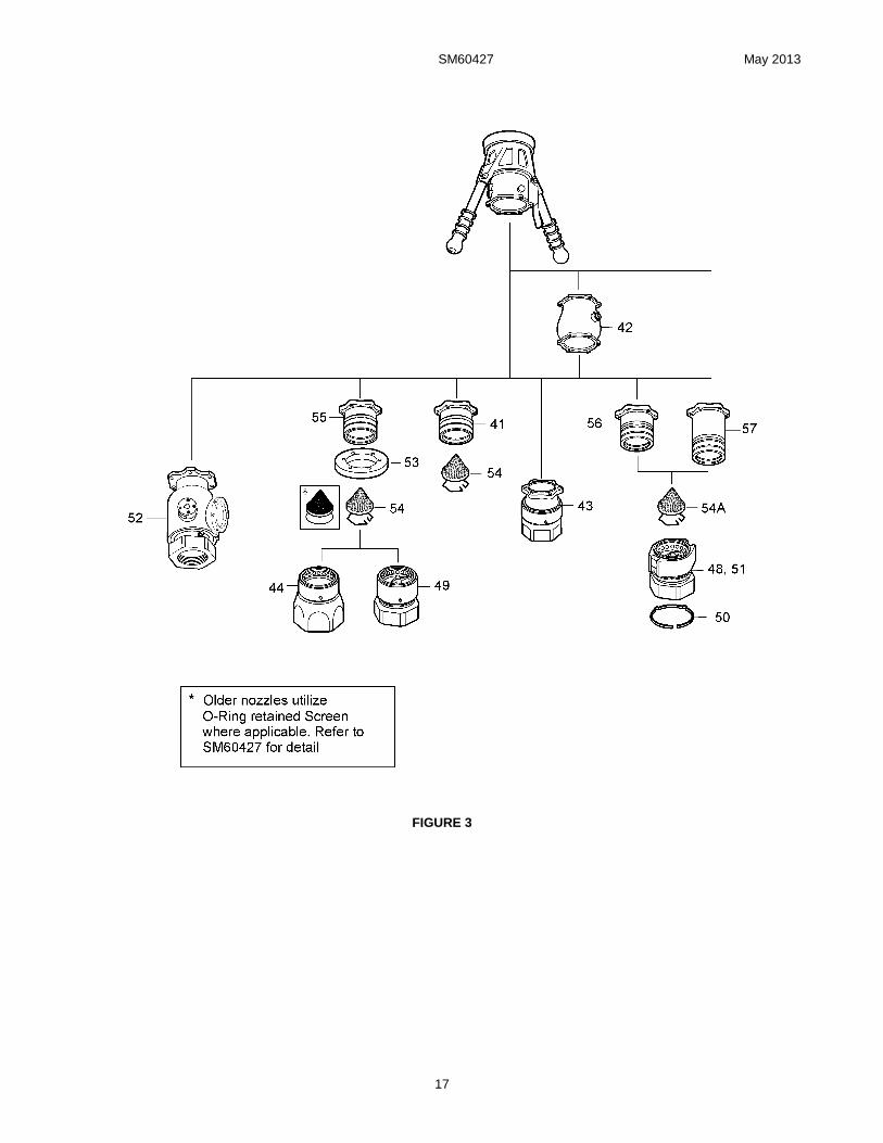
8.17 Safety Clip (50), as shown in Figure 3 is available only with options 4, 5, 7 & 8 (Part 3). The Clip (50) is installed in the groove adjacent to the red sleeve on the dry break disconnect to prevent the inadvertent movement of the sleeve until the Clip (50) is moved to the groove closest to the hose end of the unit.

SM60427 May 2013
11
9.0 TEST
The nozzle should be tested as a complete unit, including the appropriate quick disconnect, dry break and/or regulator.
9.1 Test conditions
Test media shall be Stoddard Solvent (Federal Specification P-D-680), JP-4 per MIL-J-5624D at 75° + 15°F, Jet A or equivalent.
9.3 Functional Test
9.3.1 The nozzle shall be inserted and locked into a test adapter and the nozzle valve actuated by use of the Crank Handle (21) or (21A) from the
fully closed to fully open position a minimum of five times. There shall be no evidence of binding or excessive force required for valve actuation.
9.4 Leakage Test
9.4.1 With the nozzle outlet in the normal open position, and the test adapter outlet closed, pressurize the inlet to five (5) psig and hold for one minute minimum. There shall be no evidence of external leakage from the nozzle.
9.4.2 Repeat the leakage test at 60 psig and 120 psig.
9.4.3 Close and disengage the nozzle and repeat 9.4.1 and 9.4.2.
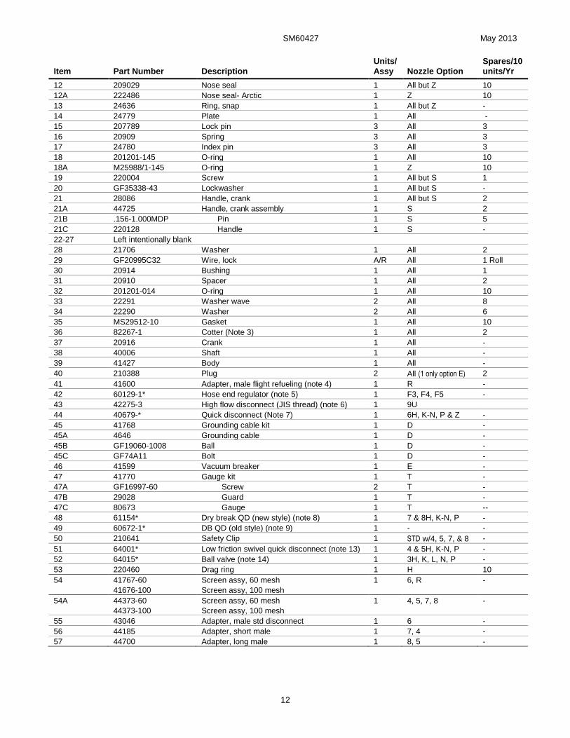
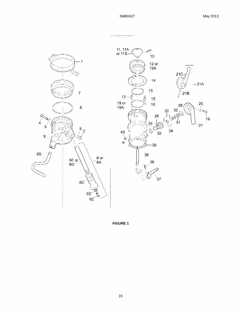
10.0 ILLUSTRATED PARTS CATALOG
Table 1.0 tabulates the parts and sub-assemblies comprising the 60427 nozzle. The item numbers of the table are keyed to the
exploded views of the regulator diagrammed in Figures 1, 2, and 3.
TABLE 1.0
Item Part Number Description
Units/
Assy Nozzle Option
Spares/10
units/Yr
1 207799 Cover assembly 1 All 10
No number 43003-1 Handle assy set, 10" (Note 10) 1 All but G, S & V 2
2 MS21042-4 Nut, self-locking 2 All -
3 Left intentionally blank
4 GF4-13A Bolt, hex head 2 All -
5 GF960-416 Washer 4 All
6 203241-1 Handle, 10" 2 All but G, S & V
6C 207808 Grip 1 All but S & V 5
6D GF960-516 Washer 1 All but S & V -
6E GF16997-78L Cap screw 1 All but S & V -
6F 220000 Handle 1 All but G, S & V -
No number 43003-2 Handle assy set, 15" (Note 10) 1 G 2
2 MS21042-4 Nut, self-locking 2 All -
3 Left intentionally blank
4 GF4-13A Bolt, hex head 2 All -
5 GF960-416 Washer 4 All -
6A 203241-2 Handle, 15" 2 G -
6C 207808 Grip 2 All but S & V 5
6D GF960-516 Washer 2 All but S & V -
6E GF16997-78L Cap screw 2 All but S & V -
6G 220001 Handle 2 G
No number 43003-3 Handle assy set, stirrup (note 10) 1 S 2
2 MS21042-4 Nut, self-locking 2 All -
3 Left intentionally blank
4 GF4-13A Bolt, hex head 2 All -
5 GF960-416 Washer 4 All -
6B 200479 Handle, stirrup 2 S -
7 23622 Bumper 1 All 10
8 23620 Bearing 1 All 3
9 28085 Collar 1 All 2
10 GF24665-302 Cotter Pin 1 All 10
11 26866 Poppet-std. (green-obsolete) 1 All but Y & Z 1
11 210593 Poppet-std. (gold - current Note 11) 1 All but Y 1
11A 29649 Poppet - Russian (black) 1 Y 1
SM60427 May 2013
12
Item Part Number Description
Units/
Assy Nozzle Option
Spares/10
units/Yr
12 209029 Nose seal 1 All but Z 10
12A 222486 Nose seal- Arctic 1 Z 10
13 24636 Ring, snap 1 All but Z -
14 24779 Plate 1 All -
15 207789 Lock pin 3 All 3
16 20909 Spring 3 All 3
17 24780 Index pin 3 All 3
18 201201-145 O-ring 1 All 10
18A M25988/1-145 O-ring 1 Z 10
19 220004 Screw 1 All but S 1
20 GF35338-43 Lockwasher 1 All but S -
21 28086 Handle, crank 1 All but S 2
21A 44725 Handle, crank assembly 1 S 2
21B .156-1.000MDP Pin 1 S 5
21C 220128 Handle 1 S -
22-27 Left intentionally blank
28 21706 Washer 1 All 2
29 GF20995C32 Wire, lock A/R All 1 Roll
30 20914 Bushing 1 All 1
31 20910 Spacer 1 All 2
32 201201-014 O-ring 1 All 10
33 22291 Washer wave 2 All 8
34 22290 Washer 2 All 6
35 MS29512-10 Gasket 1 All 10
36 82267-1 Cotter (Note 3) 1 All 2
37 20916 Crank 1 All -
38 40006 Shaft 1 All -
39 41427 Body 1 All -
40 210388 Plug 2 All (1 only option E) 2
41 41600 Adapter, male flight refueling (note 4) 1 R -
42 60129-1* Hose end regulator (note 5) 1 F3, F4, F5 -
43 42275-3 High flow disconnect (JIS thread) (note 6) 1 9U
44 40679-* Quick disconnect (Note 7) 1 6H, K-N, P & Z -
45 41768 Grounding cable kit 1 D -
45A 4646 Grounding cable 1 D -
45B GF19060-1008 Ball 1 D -
45C GF74A11 Bolt 1 D -
46 41599 Vacuum breaker 1 E -
47 41770 Gauge kit 1 T -
47A GF16997-60 Screw 2 T -
47B 29028 Guard 1 T -
47C 80673 Gauge 1 T --
48 61154* Dry break QD (new style) (note 8) 1 7 & 8H, K-N, P -
49 60672-1* DB QD (old style) (note 9) 1 - -
50 210641 Safety Clip 1 STD w/4, 5, 7, & 8 -
51 64001* Low friction swivel quick disconnect (note 13) 1 4 & 5H, K-N, P -
52 64015* Ball valve (note 14) 1 3H, K, L, N, P -
53 220460 Drag ring 1 H 10
54 41767-60
41676-100
Screen assy, 60 mesh
Screen assy, 100 mesh
1 6, R -
54A 44373-60
44373-100
Screen assy, 60 mesh
Screen assy, 100 mesh
1 4, 5, 7, 8 -
55 43046 Adapter, male std disconnect 1 6 -
56 44185 Adapter, short male 1 7, 4 -
57 44700 Adapter, long male 1 8, 5 -

SM60427 May 2013
13
Kits
KD60427–1 Parts necessary for a seal change for the 604276H, 6K-6P & 6Z options (old part number
60427J). Consists of items 10, 12, 18, 28, 32, 33, 35 & 36 above plus 201201-231 &
201201-151 O-rings. Replaces old kit 80676.
KD60427–2 Parts to make the seal change as in KD60427-1 above plus parts to replace the seals in a
hose end regulator (options F3, F4 or F5). Contains KD60427-1 plus KD60129-1.
KD60427–3 Parts to include seal changes to the basic nozzle (KD60427-1) plus the o-ring to repair the
old style dry break disconnect 60672-1. Contains KD60427-1 plus 201201-233.
KD60427–4 KD60427-2 plus KD60427-3 to repair a 60427 nozzle with hose end regulator plus 60672-
1 dry break disconnect.
KD60427–5 Parts to repair the 60427 nozzle (KD60427-1) plus parts to repair the 61154 new style dry
break disconnect. Contains KD60427-1 plus KD61154-1.
KD60427–6 Parts to repair the 60427 nozzle plus parts to repair the hose end regulator and 61154 dry
break disconnect. Contains KD60427-1, KD60129-1 and KD61154-1.
KD60427–7 Parts to provide replacements to allow use of common current production poppet with
60427 nozzle. Contains items 10, 11 (210593) & 38.
KD60427–8 Parts to perform a major overhaul for the 604276H, 6K-6P & 6Z - consists of items 1, 6C,
7, 8, 9, 10, 12, 18, 28, 32, 33, 35 & 36 above plus 201201-231, & 201201-151 O-rings.
KD60427–9 Parts necessary for a seal change for the 604276H, 6K-6P options (old part number
60427J). Identical to the –3 kit except the O-ring material is fluorosilicone. Consists of
items 10, 12, 18 (M25988/1-145), 28, 32 (M25988/1-014), 33, 35 (M25988/1-910) & 36
above plus M25988/1-231, M25988/1-151, M25988/1-233 & M25988/1-039 O-rings.
Notes: 1. All part numbers beginning with "GF" are interchangeable with those beginning with either "AN" or "MS". If
the "GF" is followed by three numbers it is interchangeable with an "AN" part, otherwise it is interchangeable
with an "MS" part of the same number.
2. The recommended spare parts shown above are the number required to support 10 Units for one year or
each overhaul whichever is sooner. These quantities do not include replacement spares for intermediate
replacement of parts required by abuse or misuse of the equipment. The recommended quantities are based
on the ratio of spare parts sold for each unit during a one year period of time. The actual quantity required will
vary from location to location.
3. 82267-2 replaces 82267-1 for oversize hole applications.
4. Refer to SM427MISC for parts listing.
5. Refer to SM60129-1 for parts listing. * indicates that there is additional information required to complete the
part number since there is more than one regulator available.
6. Refer to SM42275 for parts listing.
7. Refer to SM40679 for parts listing. * means that there is additional information required to complete the part
number.
8. Refer to SM61154 for parts listing. * means that there is additional information required to complete the part
number.
9. Refer to SM60672-1 for parts listing. * means that there is additional information required to complete the part
number. This item has been superseded by 61154 and is no longer available as an option to the 60427
nozzle.
10. Handle Assy 43003-1, -2 and -3 include all of the parts shown indented under their respective listings.
Example: 43003-1 includes 2 each of items 2-6 (item 6 includes 6C, 6D, 6E & 6F).
11. 210593 Poppet (11) can be used only with Shaft (38) which has two holes present in the threaded end of the
part. Rework instructions are shown in Figure 5).
12. Option Y, nose seal and poppet to fit older Russian aircraft, can utilize either the obsolete 29650 or the
current production 209029 interchangeably.
13. Refer to SM64001 for parts listing. * means that there is additional information required to compete the part
number.
14. Refer to SM64015 for parts listing. * means that there is additional information required to compete the part
number.

SM60427 May 2013
14
TABLE 2.0
Torque Specifications 60427
Fig. Item Part Number Description Torque in.-lb.
1 30 20914 Bushing 120-150 in.-lb. (138 - 173 kg-cm)
SM60427 May 2013
15
FIGURE 1

SM60427 May 2013
16
FIGURE 2
SM60427 May 2013
17
FIGURE 3

SM60427 May 2013
18
FIGURE 4
SHAFT REWORK INSTRUCTIONS

SM60427 May 2013
19
FIGURE 6
POPPET – SHAFT RETENTION

SM60427 May 2013
20
11.0 FAILURE MODES AND EFFECTS ANALYSIS - Nozzle
11.1 Notes that apply to this analysis:
A. Hazard category, hazard probability, and real hazard index (RHI) are defined herein.
B. “Visual inspection” means examining the nozzle for obvious cracks, damage, and broken lugs, prior to initial pressurization.
C. “Pressure test prior to use” means pressurizing the nozzle and attached hose to operating fuel pressure, then removing pressure, prior to aircraft arrival.
D. “Shut off fuel at source” will be the first action for any leak. To further improve operating safety, this procedure should be used for all refueling operations. In addition, fuel flow should be turned on at the source, not at the nozzle.
E. Item numbers referred to in this section are those used in Figure 5.
11.2 RISK ASSESSMENT - A risk assessment procedure based upon the hazard probability, as well as hazard severity may be required to establish priorities for corrective action and resolution of identified hazards. One example is the real hazard index; a numeric rank ordering of a mathematical combination arrived at by assigning numerical values to the severity category and probability level.
A. Hazard Probability - The probability that a hazard will occur during the planned life expectancy of the system can be described in potential occurrences per unit of time, event, population, item or activity. Assigning a quantitative hazard is generally not possible early in the design process. A qualitative hazard probability may be derived from research, and evaluation of historical safety data from similar systems.
Level Descriptive word Specific Individual Item Fleet or Inventory
A (6) Frequent Likely to occur frequently Continuously experienced
B (5) Reasonably probable Will occur several times in life of an item Will occur frequently
C (4) Occasional Likely to occur sometimes in the life of an item Will occur several times
D (3) Remote So unlikely, it can be assumed that this hazard will not be experienced
Unlikely to occur but possible
E (2) Extremely Improbable Probability of occurrence cannot be distinguished from zero
So unlikely it can be assumed that this hazard will not be experienced
F (1) Impossible Physically impossible to occur Physically impossible
B. Hazard Severity - Hazard severity categories are defined to provide a qualitative measure of the worst potential consequences resulting from personnel error, environmental conditions, design inadequacies, procedural deficiencies, or system, subsystem or component failure/ malfunction.
Severity Category Descriptive word Results
I (4) Catastrophic May cause death or system loss
II (3) Critical May cause severe injury, or system damage
III (2) Marginal May cause minor injury, minor occupational illness, or minor system damage
IV (1) Negligible Will not result in injury, occupational illness, or system damage
C. Real Hazard Index (RHI) Matrix - (RHI = Hazard Severity X Probability Level)
HAZARD SEVERITY
I (4) II (3) III (2) IV (1) A (6) 24 18 12 6 B (5) 20 15 10 5 PROBABILITY C (4) 16 12 8 4 LEVEL D (3) 12 9 6 3 E (2) 8 6 4 2 F (1) 4 3 2 1
General guidelines for required action. RHI
1-8 No action required.
9-12 Special precautions required, investigate redesign.
13-24 Hazardous, redesign necessary or procedural control if redesign is impractical.
SM60427 May 2013
21
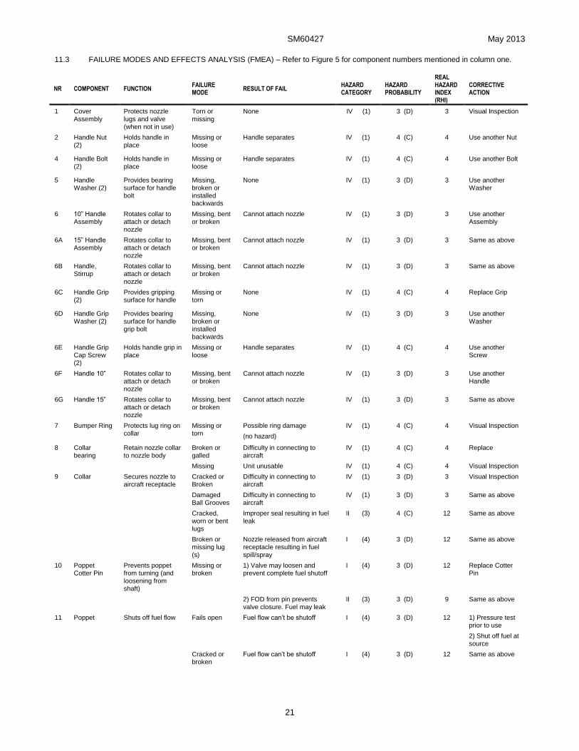
11.3 FAILURE MODES AND EFFECTS ANALYSIS (FMEA) – Refer to Figure 5 for component numbers mentioned in column one.
NR COMPONENT FUNCTION FAILURE MODE
RESULT OF FAIL HAZARD CATEGORY
HAZARD PROBABILITY
REAL HAZARD INDEX (RHI)
CORRECTIVE ACTION
1 Cover Assembly
Protects nozzle lugs and valve (when not in use)
Torn or missing
None IV (1) (1) 3 (D) 3 Visual Inspection
2 Handle Nut (2)
Holds handle in place
Missing or loose
Handle separates IV (1) 4 (C) 4 Use another Nut
4 Handle Bolt (2)
Holds handle in place
Missing or loose
Handle separates IV (1) 4 (C) 4 Use another Bolt
5 Handle Washer (2)
Provides bearing surface for handle bolt
Missing, broken or installed backwards
None IV (1) 3 (D) 3 Use another Washer
6 10” Handle Assembly
Rotates collar to attach or detach nozzle
Missing, bent or broken
Cannot attach nozzle IV (1) 3 (D) 3 Use another Assembly
6A 15” Handle Assembly
Rotates collar to attach or detach
nozzle
Missing, bent or broken
Cannot attach nozzle IV (1) 3 (D) 3 Same as above
6B Handle, Stirrup
Rotates collar to attach or detach nozzle
Missing, bent or broken
Cannot attach nozzle IV (1) 3 (D) 3 Same as above
6C Handle Grip (2)
Provides gripping surface for handle
Missing or torn
None IV (1) 4 (C) 4 Replace Grip
6D Handle Grip Washer (2)
Provides bearing surface for handle grip bolt
Missing, broken or installed backwards
None IV (1) 3 (D) 3 Use another Washer
6E Handle Grip Cap Screw (2)
Holds handle grip in place
Missing or loose
Handle separates IV (1) 4 (C) 4 Use another Screw
6F Handle 10” Rotates collar to attach or detach nozzle
Missing, bent or broken
Cannot attach nozzle IV (1) 3 (D) 3 Use another Handle
6G Handle 15” Rotates collar to attach or detach nozzle
Missing, bent or broken
Cannot attach nozzle IV (1) 3 (D) 3 Same as above
7 Bumper Ring Protects lug ring on collar
Missing or torn
Possible ring damage
(no hazard)
IV (1) 4 (C) 4 Visual Inspection
8 Collar bearing
Retain nozzle collar to nozzle body
Broken or galled
Difficulty in connecting to aircraft
IV (1) 4 (C) 4 Replace
Missing Unit unusable IV (1) 4 (C) 4 Visual Inspection
9 Collar Secures nozzle to aircraft receptacle
Cracked or Broken
Difficulty in connecting to aircraft
IV (1) 3 (D) 3 Visual Inspection
Damaged Ball Grooves
Difficulty in connecting to aircraft
IV (1) 3 (D) 3 Same as above
Cracked, worn or bent lugs
Improper seal resulting in fuel leak
II (3) 4 (C) 12 Same as above
Broken or missing lug (s)
Nozzle released from aircraft receptacle resulting in fuel spill/spray
I (4) 3 (D) 12 Same as above
10 Poppet Cotter Pin
Prevents poppet from turning (and loosening from shaft)
Missing or broken
1) Valve may loosen and prevent complete fuel shutoff
I (4) 3 (D) 12 Replace Cotter Pin
2) FOD from pin prevents valve closure. Fuel may leak
II (3) 3 (D) 9 Same as above
11 Poppet Shuts off fuel flow Fails open Fuel flow can’t be shutoff I (4) 3 (D) 12 1) Pressure test prior to use
2) Shut off fuel at source
Cracked or broken
Fuel flow can’t be shutoff I (4) 3 (D) 12 Same as above

SM60427 May 2013
22
NR COMPONENT FUNCTION FAILURE MODE
RESULT OF FAIL HAZARD CATEGORY
HAZARD PROBABILITY
REAL HAZARD INDEX (RHI)
CORRECTIVE ACTION
Fails closed Cannot refuel IV (1) 3 (D) 3 Same as above
12 Nose Seal Seals poppet valve in body
Torn or broken
Fuel Spray I (4) 3 (D) 12 Replace Nose Seal
13 Snap Ring Holds Plate onto Nose Seal
Missing or broken
Nose seal does not stay completely in place; minor fuel leak
II (3) 2 (E) 6 Replace Snap Ring
Poppet valve may be blocked from closing
II (3) 2 (E) 6 Shutoff fuel at source. Aircraft poppet valve will prevent backflow
14 Nose Seal Plate
Attaches Nose Seal to Nozzle Body
Cracked or loose
Fuel spray I (4) 3 (D) 12 Pressure test prior to use
15 Lock Pin (3) Prevents rotation of nozzle collar
Missing 1 or 2 None IV (1) 3 (E) 3 Replace Lock Pin(s)
Stuck retracted (1 or 2)
None IV (1) 3 (E) 3 Same as above
Missing all 3 Loss of nozzle collar interlock. Can flow fuel without nozzle attached to aircraft
I (4) 3 (D) 12 Procedural error also needed for fuel spill. Valve link has overcenter feature to prevent fuel pressure from opening valve
Stuck retracted (All 3)
Same I (4) 3 (D) 12 Same as above
Stuck extended
Cannot attach nozzle to aircraft
IV (1) 3 (E) 3 Replace Lock Pin
Installed backwards or upside down
Cannot assemble nozzle IV (1) 3 (E) 3 Install Correctly
16 Lock Pin Spring (3)
Keeps Lock Pin extended
Missing or broken (1 or 2)
None IV (1) 3 (E) 3 Replace Lock Spring(s)
Missing or broken (All 3)
Loss of collar interlock (depending on orientation of aircraft receptacle)
Can flow fuel without nozzle attached to aircraft
I (4) 3 (D) 12 Same as above
17 Index Pin (3) Provides proper alignment between nozzle and aircraft receptacle
Missing 1 or 2 None IV (1) 3 (E) 3 Replace Index Pin
Missing all 3 Difficulty attaching nozzle to aircraft
IV (1) 3 (E) 3
Same as above
18 Body O-Ring Provides seal
between body and valve seat assembly
Missing Fuel Spray I (4) 3 (D) 12 Pressure test prior
to use
Torn or broken
Fuel leak II (3) 3 (D) 9 Same as above
18A
Body O-Ring Provides seal between body and valve seat assembly
Missing Fuel Spray I (4) 3 (D) 12 Pressure test prior to use
Torn or broken
Fuel leak II (3) 3 (D) 9 Same as above
19 Handle Screw
Holds Crank Handle in place
Missing or loose
Handle separates IV (1) 4 (C) 4 Use another handle

SM60427 May 2013
23
NR COMPONENT FUNCTION FAILURE MODE
RESULT OF FAIL HAZARD CATEGORY
HAZARD PROBABILITY
REAL HAZARD INDEX (RHI)
CORRECTIVE ACTION
20 Handle Lock Washer
Provides bearing surface for Crank Handle Screw
Missing or broken
None IV (1) 3 (D) 3 Replace Lock Washer
21 Crank Handle
1) Applies force to open poppet valve
Bent shaft Difficulty in use (binding) IV (1) 3 (D) 3 Replace Crank Handle
2) Prevents collar from rotating
Broken shaft 1) Poppet valve opens; cannot stop fuel flow
I (4) 3 (D) 12 1) Pressure test prior to use
2) Shut off fuel at source
2) Crank handle may come off and release fuel
I (4) 3 (D) 12 Same as above
Broken locking lug
Possible to rotate collar while refueling; nozzle separates; massive fuel spill
I (4) 3 (D) 12 Prior to refuel, verify integrity by attempting to rotate collar with handle “open” and nozzle attached to aircraft
28 Washer Provides bearing surface for Crank Handle
Missing or broken
Premature wear between operating handle and bushing spacer
IV (1) 3 (D) 3 Replace Washer
29 Lock Wire Locks bushing to housing
Missing or broken
Precaution to prevent premature unthreading of the bushing
IV (1) 3 (D) 3 Replace Wire Lock
30 Busing Provides clearance between nozzle body and Crank Handle
Missing or broken
Worn or gulled
Non-functional
Fuel leaking
IV (1) 3 (D) 3 Replace Bushing
31 Spacer Retains o-ring Missing or broken
Fuel leaking IV (1) 3 (D) 3 Replace Spacer
32 O-Ring Provides seal between crank shaft and Body
Missing Fuel Spray I (4) 3 (D) 12 Pressure test prior to use
33 Wave Washer
Provides crankshaft tension
Missing or broken
Additional play between nozzle body and operating handle
IV (1) 3 (D) 3 Replace Wave Washer
34 Washer Provides bearing
surface Wave Washers
Missing or
broken
None IV (1) 3 (D) 3 Replace Washer
35 Gasket Provides seal between Body and Bushing
Missing Fuel Spray I (4) 3 (D) 12 Pressure test prior to use
36 Crank Cotter Pin
Prevents Crank from separating from Crank Shaft
Missing or broken
1) Crank may loosen and prevent complete fuel shutoff
I (4) 3 (D) 12 Replace Cotter Pin
37 Crank Connects poppet to Crank handle assembly (In-Line with valve link)
Broken Poppet valve opens; cannot stop fuel flow
I (4) 3 (D) 12 1) Pressure test prior to use
2) Shut off fuel at source
Bent Difficult to open or close valve III (2) 3 (D) 6 Same as above
38 Crank Shaft Connects Poppet Valve to crank assembly (in line with shaft).
Broken Poppet valve fails open; cannot stop fuel flow
I (4) 3 (D) 12 Same as above
Bent Difficult to open or close valve III (2) 3 (D) 6 Same as above
Installed backwards
Cannot open valve fully IV (1) 3 (D) 3
39 Body Holds all components together
Cracked 1) Fuel leak
2) Difficulty in attaching to aircraft
I (4)
IV (1)
3 (D)
3 (D)
12
3
1) Pressure test prior to use
2) Visual Inspection
40 Access Port Plug (2)
Provides access for applying pressure gauge or other accessories
Missing Massive fuel spill I (4) 3 (D) 12 Same as above
SM60427 May 2013
24
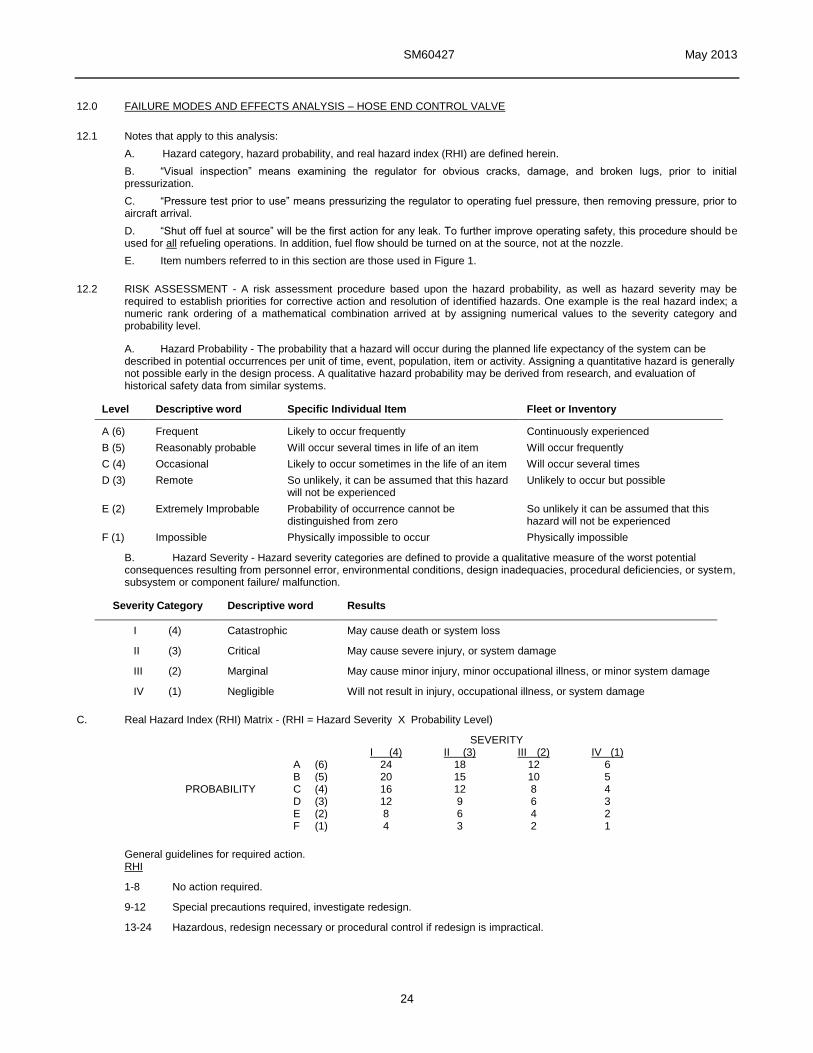
12.0 FAILURE MODES AND EFFECTS ANALYSIS – HOSE END CONTROL VALVE
12.1 Notes that apply to this analysis:
A. Hazard category, hazard probability, and real hazard index (RHI) are defined herein.
B. “Visual inspection” means examining the regulator for obvious cracks, damage, and broken lugs, prior to initial pressurization.
C. “Pressure test prior to use” means pressurizing the regulator to operating fuel pressure, then removing pressure, prior to aircraft arrival.
D. “Shut off fuel at source” will be the first action for any leak. To further improve operating safety, this procedure should be used for all refueling operations. In addition, fuel flow should be turned on at the source, not at the nozzle.
E. Item numbers referred to in this section are those used in Figure 1.
12.2 RISK ASSESSMENT - A risk assessment procedure based upon the hazard probability, as well as hazard severity may be required to establish priorities for corrective action and resolution of identified hazards. One example is the real hazard index; a numeric rank ordering of a mathematical combination arrived at by assigning numerical values to the severity category and probability level.
A. Hazard Probability - The probability that a hazard will occur during the planned life expectancy of the system can be described in potential occurrences per unit of time, event, population, item or activity. Assigning a quantitative hazard is generally not possible early in the design process. A qualitative hazard probability may be derived from research, and evaluation of historical safety data from similar systems.
Level Descriptive word Specific Individual Item Fleet or Inventory
A (6) Frequent Likely to occur frequently Continuously experienced
B (5) Reasonably probable Will occur several times in life of an item Will occur frequently
C (4) Occasional Likely to occur sometimes in the life of an item Will occur several times
D (3) Remote So unlikely, it can be assumed that this hazard will not be experienced
Unlikely to occur but possible
E (2) Extremely Improbable Probability of occurrence cannot be distinguished from zero
So unlikely it can be assumed that this hazard will not be experienced
F (1) Impossible Physically impossible to occur Physically impossible
B. Hazard Severity - Hazard severity categories are defined to provide a qualitative measure of the worst potential consequences resulting from personnel error, environmental conditions, design inadequacies, procedural deficiencies, or system, subsystem or component failure/ malfunction.
Severity Category Descriptive word Results
I (4) Catastrophic May cause death or system loss
II (3) Critical May cause severe injury, or system damage
III (2) Marginal May cause minor injury, minor occupational illness, or minor system damage
IV (1) Negligible Will not result in injury, occupational illness, or system damage
C. Real Hazard Index (RHI) Matrix - (RHI = Hazard Severity X Probability Level)
SEVERITY I (4) II (3) III (2) IV (1)
PROBABILITY
A (6) 24 18 12 6 B (5) 20 15 10 5 C (4) 16 12 8 4 D (3) 12 9 6 3 E (2) 8 6 4 2 F (1) 4 3 2 1
General guidelines for required action. RHI
1-8 No action required.
9-12 Special precautions required, investigate redesign.
13-24 Hazardous, redesign necessary or procedural control if redesign is impractical.
SM60427 May 2013
25
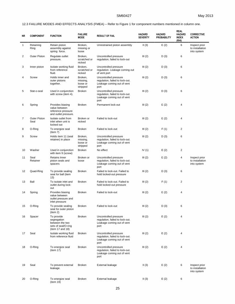
12.3 FAILURE MODES AND EFFECTS ANALYSIS (FMEA) – Refer to Figure 1 for component numbers mentioned in column one.
NR COMPONENT FUNCTION FAILURE MODE
RESULT OF FAIL HAZARD SEVERITY
HAZARD PROBABILITY
REAL HAZARD INDEX (RHI)
CORRECTIVE ACTION
1 Retaining Ring
Retain piston assembly against spring force.
Broken, missing or loose
Unrestrained piston assembly II (3) E (2) 6 Inspect prior to installation into system
2 Outer Piston Regulate outlet pressure.
Broken, scratched or nicked
Uncontrolled pressure regulation, failed to lock-out
III (2) D (3) 6
3 Inner piston Isolate working fluid from reference fluid.
Broken, scratched or nicked
Uncontrolled pressure regulation. Leakage coming out of vent port
III (2) D (3) 6
4 Screw Holds inner and outer pistons together.
Broken, missing, loose or stripped
Uncontrolled pressure regulation, failed to lock-out. Leakage coming out of vent port
III (2) D (3) 6
5 Stat-o-seal Used in conjunction with screw (item 4).
Broken Uncontrolled pressure regulation, failed to lock-out. Leakage coming out of vent port
III (2) D (3) 6
6 Spring Provides biasing value between reference pressure and outlet pressure.
Broken Permanent lock-out III (2) E (2) 4
7 Outer Piston Seal
Isolate outlet from inlet when unit is locked out
Broken or nicked
Failed to lock-out III (2) E (2) 4
8 O-Ring To energize seal (item 7)
Broken Failed to lock-out III (2) F (1) 2
9 Screw Holds item 11 (seal retainer) in place
Broken, missing, loose or stripped
Uncontrolled pressure regulation, failed to lock-out. Leakage coming out of vent port
III (2) D (3) 6
10 Washer Used in conjunction with item 9 (screw)
Broken No effect IV (1) E (2) 2
11 Seal Retainer
Retains Inner piston seals and spacers
Broken or loose
Uncontrolled pressure regulation, failed to lock-out. Leakage coming out of vent port
III (2) E (2) 4 Inspect prior to installation into system
12 Quad-Ring To provide sealing seat for ball (item 13)
Broken Failed to lock-out. Failed to hold locked-out pressure
III (2) D (3) 6
13 Ball To isolate inlet and outlet during lock-out
Broken Failed to lock-out. Failed to hold locked-out pressure
III (2) F (1) 2
14 Spring Provides biasing value between outlet pressure and inlet pressure
Broken Failed to lock-out III (2) E (2) 4
15 O-Ring To provide sealing seat for outer piston (item 2)
Broken Failed to lock-out III (2) D (3) 6
16 Spacer To provide segregation between the two sets of seal/O-ring (item 17 and 18)
Broken Uncontrolled pressure regulation, failed to lock-out. Leakage coming out of vent port
III (2) E (2) 4
17 Seal Isolate working fluid from reference fluid
Broken Uncontrolled pressure regulation, failed to lock-out.
Leakage coming out of vent port
III (2) E (2) 4
18 O-Ring To energize seal (item 17)
Broken Uncontrolled pressure regulation, failed to lock-out. Leakage coming out of vent port
III (2) E (2) 4
19 Seal To prevent external leakage.
Broken External leakage II (3) E (2) 6 Inspect prior to installation into system
20 O-Ring To energize seal (item 19)
Broken External leakage II (3) E (2) 6

SM60427 May 2013
26
NR COMPONENT FUNCTION FAILURE MODE
RESULT OF FAIL HAZARD SEVERITY
HAZARD PROBABILITY
REAL HAZARD INDEX (RHI)
CORRECTIVE ACTION
21 Breather Assembly
To prevent atmospheric contaminants from entering inner piston cavity
Missing or loose
Contamination of inner piston cavity
IV (1) E (2) 2 Inspect prior to use
25 Screw Assembly
To provide containment for balls (item 27) and to prevent external leakage
Broken or loose
External leakage II (3) E (2) 6 Inspect prior to use
26 O-Ring To prevent external leakage.
Broken External leakage II (3) E (2) 6
27 Ball Bearing To secure mechanical connection to mating part
Broken Damage ball race IV (1) F (1) 1
28 O-Ring To prevent external leakage.
Broken External leakage II (3) E (2) 6 Inspect prior to installation into system
29 Housing Assembly
House all components
Cracked External leakage. Total failure I (4) E (2) 8 Inspect prior to use
29B
Outer Wear Ring
Provide harden bearing surface to protect aluminum housing
Broken Exposing aluminum housing ball bearing race to wear.
III (2) E (2) 4
29C
Inner Wear Ring
31A
Continuity clip
To provide electrical continuity (bonding) to mating component
Broken No ESD protection II (3) E (2) 6

Aerospace Group Fluid & Electrical Distribution Division 9650 Jeronimo Road Irvine, CA 92618 Ph (949) 452-9500 Fax (949) 452-9992