Embed Size (px)
Citation preview
SE95004 Rev. 9August 2012
Cleveland™
Maintenance Procedures& Parts Lists Electric Table Top Kettles
For units built after April 2010
1333 East 179th St., Cleveland, Ohio, U.S.A. 44110Ph: 216.481.4900 Fx: 216.481.3782www.clevelandrange.com
For your future reference.
Model # ______________________________________
Serial # _______________________________________
This manual is to be used in conjunction with the“Operators Manual”. See “Operators Manual” forsafety warnings, correct operation, installationand preventative maintenance.
KET-3-TKET-6-TKET-12-TKET-20-TTKET-3-TTKET-6-TTKET-12-T
Model # & Serial #.
Read the manual thoroughly.Improper installation, operation ormaintenance can cause propertydamage, injury or death.
0
!
0
!
STATEMENT OF RESPONSIBILITIES /DÉCLARATION DES RESPONSABILITÉS / DECLARACIÓN DE RESPONSABILIDADES
This document is for use by experiencedand trained Qualified Cleveland Range,LLC Authorized Service Representativeswho are familiar with both the safetyprocedures, and equipment theyservice. Cleveland Range, LLC assumesno liability for any death, injury,equipment damage, or property damageresulting from use of, improper use of,or failure to use the informationcontained in this document. ClevelandRange, LLC has made every effort toprovide accurate information in thisdocument, but cannot guarantee thatthis document does not containunintentional errors and omissions.
The information in this document maybe subject to technical and technologicalchanges, revisions, or updates.Cleveland Range, LLC assumes noliability or responsibility regarding errata,changes, revisions, or updates.
Qualified Cleveland Range, LLCAuthorized Service Representatives areobligated to follow industry standardsafety procedures, including, but notlimited to, OSHA regulations, anddisconnect / lock out / tag outprocedures for all utilities includingsteam, and disconnect / lock out / tagout procedures for gas, electric, andsteam powered equipment and / orappliances.
All utilities (gas, electric, water andsteam) should be turned OFF to theequipment and locked out of operationaccording to OSHA approved practicesduring any servicing of Cleveland Rangeequipment
Qualified Cleveland Range, LLCAuthorized Service Representatives areobligated to maintain up-to-dateknowledge, skills, materials andequipment.
Ce document est destiné à l’usage desReprésentants de Service qualifiés etautorisés de Cleveland Range, LLC quipossèdent l’expérience et la formation ainsique la bonne connaissance des mesuresde sécurité et du matériel qu’ilsentretiennent.
Cleveland Range, LLC décline touteresponsabilité pour tout cas de décès,blessure, dommage matériel ou dommageaux biens résultant de l'utilisation, de lamauvaise utilisation ou du manquementd’utilisation des renseignements contenusdans ce document.
Cleveland Range, LLC s’est efforcé àfournir des renseignements précis dans cedocument mais ne peut garantir que cedocument soit exempt d’erreurs etd’omissions non intentionnelles.
Les renseignements contenus dans cedocument peuvent être assujettis à deschangements techniques et technologiques,des révisions ou des mises à jour.
Cleveland Range, LLC décline touteobligation ou responsabilité concernant leserrata, modifications, révisions ou mises àjour.
Les Représentants de Service qualifiés etautorisés de Cleveland Range, LLC sonttenus de se conformer aux mesures desécurité normalisées de l’industrie, ycompris, mais sans s'y limiter, lesréglementations de l'OSHA, les procéduresde débranchement / verrouillage /étiquetage relatives à tous les servicespublics, dont l’approvisionnement envapeur, et les procédures dedébranchement / verrouillage / étiquetagerelatives aux équipements et/ou appareilsfonctionnant au gaz, à l’électricité et à lavapeur.
Au cours de tout entretien d’un appareilCleveland Range, tous les services publics(gaz, électricité, eau et vapeur) doivent êtreFERMÉS au niveau de l’appareil et ledispositif de fonctionnement doit êtreverrouillé suivant les pratiques approuvéesde l’OSHA.
Les Représentants de Service qualifiés etautorisés de Cleveland Range, LLC sonttenus d’actualiser en permanence leursconnaissances, compétences, matériel etéquipement.
Este documento está destinado para el usode los Representantes de Serviciocalificados y autorizados de ClevelandRange, LLC quienes cuentan con laexperiencia y la capacitación así como elbuen conocimiento de las medidas deseguridad y de los equipos que mantienen.
Cleveland Range, LLC, declina todaresponsabilidad en caso de cualquierfallecimiento, lesiones, daños al equipo odaños a la propiedad resultantes de lautilización, del uso indebido o de la falta deutilización de la información provista en estedocumento.
Cleveland Range, LLC se ha esforzado ensuministrar información precisa en estedocumento, pero no puede garantizar queeste documento esté exento de errores y deomisiones no intencionales.
La información contenida en estedocumento podría estar sujeta a cambiostécnicos o tecnológicos, revisiones oactualizaciones. Cleveland Range, LLCdeclina toda obligación o responsabilidadcon respecto a erratas, modificaciones,revisiones o actualizaciones.
Los Representantes de Servicio calificados yautorizados de Cleveland Range, LLC tienenla obligación de seguir los procedimientosestándar de seguridad de la industria; loscuales incluyen pero no se limitan a losreglamentos de la OSHA (La Administraciónde la Seguridad y Salud Ocupacionales), losprocedimientos de desconexión, cierre yetiquetado relativos a todos los serviciospúblicos incluyendo el suministro de vapor ylos procedimientos de desconexión, cierre yetiquetado para los equipos y/o aparatosque funcionan a base de gas, electricidad ovapor.
Cuando se esté dando servicio omantenimiento a un aparato de ClevelandRange, todos los servicios públicos (gas,electricidad, agua y vapor) deben estarAPAGADOS para el equipo en cuestión y sedebe seguir el procedimiento de cierre deoperaciones de acuerdo con las prácticasaprobadas por la OSHA.
Los Representantes de Servicio calificados yautorizados de Cleveland Range, LLC tienenla obligación de actualizar constantementesus conocimientos, destrezas, materiales yequipamiento.
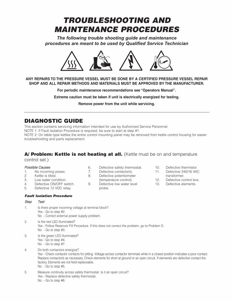
PPoossssiibbllee CCaauusseess1. No incoming power.2. Kettle is tilted.3. Low water condition.4. Defective ON/OFF switch.5. Defective 12 VDC relay.
6. Defective safety thermostat.7. Defective contactor/s.8. Defective potentiometer
(temperature control).9. Defective low water level
probe.
10. Defective thermistor.11. Defective 240/16 VAC
transformer.12. Defective control box.13. Defective elements.
DIAGNOSTIC GUIDEThis section contains servicing information intended for use by Authorized Service Personnel.NOTE 1: If Fault Isolation Procedure is required, be sure to start at step #1.NOTE 2: On table type kettles the entire control mounting panel may be removed from kettle control housing for easiertroubleshooting and parts replacement.
Fault Isolation Procedure
SStteepp TTeesstt
1. Is there proper incoming voltage at terminal block?Yes - Go to step #2.No - Correct external power supply problem.
2. Is the red LED illuminated?Yes - Follow Reservoir Fill Procedure. If this does not correct the problem, go to Problem D.No - Go to step #3.
3. Is the green LED illuminated?Yes - Go to step #4.No - Go to step #7.
4. Do both contactors energize?Yes - Check contactor contacts for pitting. Voltage across contactor terminals while in a closed position indicates a poor contact.Replace contactor/s as necessary. Check elements for short at ground or an open circuit. If element/s are defective contact thefactory. Elements are not field replaceable.No - Go to step #5.
5. Measure continuity across safety thermostat. Is it an open circuit?Yes - Replace defective safety thermostat.No - Go to step #6.
TROUBLESHOOTING AND MAINTENANCE PROCEDURESThe following trouble shooting guide and maintenance
procedures are meant to be used by Qualified Service Technician
ANY REPAIRS TO THE PRESSURE VESSEL MUST BE DONE BY A CERTIFIED PRESSURE VESSEL REPAIRSHOP AND ALL REPAIR METHODS AND MATERIALS MUST BE APPROVED BY THE MANUFACTURER.
For periodic maintenance recommendations see “Operators Manual”.
Extreme caution must be taken if unit is electrically energized for testing.
Remove power from the unit while servicing.
A/ Problem: Kettle is not heating at all. (Kettle must be on and temperaturecontrol set.)
0
0
0
0
0
!
0
!
6. Is there 120 VAC present across the coils of the contactors?Yes - Replace defective contactor/s.No - Go to step #7.
7. Remove wire from low water level probe and ground it to the body of the kettle. Do the contactors now energize?Yes - Clean or replace defective low water level probe. Replace defective red LED.No - Go to step #8.
8. Is there 16 VAC present at output of 16 VAC transformer?Yes - Go to step #9.No - Replace defective 240/16 VAC transformer.
9. Measure continuity of ON/OFF switch/ temperature control. Is it operating properly?Yes - Go to step #10.No - Replace defective ON/OFF switch/temperature control.
10. Unplug control box and measure the resistance across potentiometer. Is it approximately 0 ohms at maximum setting and50,000 ohms at minimum?Yes - Go to step #11.No - Replace defective potentiometer (ON/OFF switch/temperature control)
11. Remove edge connector from control box. While kettle is cold or thermistor is removed and allowed to cool, measure theresistance between edge connector’s pins #2 and #7. Is it approximately 100,00 ohms?Yes - Spray contact cleaner on control box terminals and edge connector. Try box again, if the problem still exists, replacedefective control box.No - Replace defective thermistor.
PPoossssiibbllee CCaauusseess1. Air in jacket requires venting.2. Defective safety thermostat.3. Defective potentiometer (temperature control).4. Defective thermistor.
5. Defective contactor/s.6. Defective control box.7. Defective elements/s.
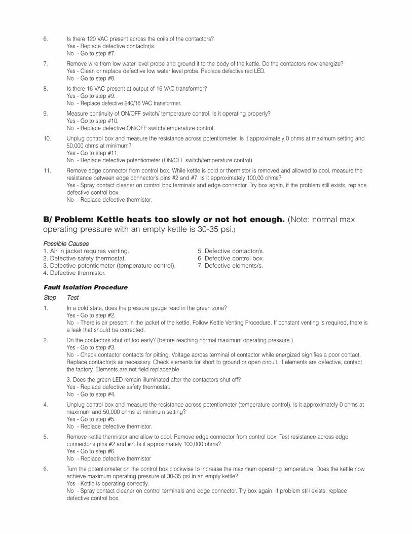
B/ Problem: Kettle heats too slowly or not hot enough. (Note: normal max.operating pressure with an empty kettle is 30-35 psi.)
Fault Isolation Procedure
SStteepp TTeesstt
1. In a cold state, does the pressure gauge read in the green zone?Yes - Go to step #2.No - There is air present in the jacket of the kettle. Follow Kettle Venting Procedure. If constant venting is required, there isa leak that should be corrected.
2. Do the contactors shut off too early? (before reaching normal maximum operating pressure.)Yes - Go to step #3.No - Check contactor contacts for pitting. Voltage across terminal of contactor while energized signifies a poor contact.Replace contactor/s as necessary. Check elements for short to ground or open circuit. If elements are defective, contactthe factory. Elements are not field replaceable.
3. Does the green LED remain illuminated after the contactors shut off?Yes - Replace defective safety thermostat.No - Go to step #4.
4. Unplug control box and measure the resistance across potentiometer (temperature control). Is it approximately 0 ohms atmaximum and 50,000 ohms at minimum setting?Yes - Go to step #5.No - Replace defective thermistor.
5. Remove kettle thermistor and allow to cool. Remove edge connector from control box. Test resistance across edgeconnector's pins #2 and #7. Is it approximately 100,000 ohms?Yes - Go to step #6.No - Replace defective thermistor
6. Turn the potentiometer on the control box clockwise to increase the maximum operating temperature. Does the kettle nowachieve maximum operating pressure of 30-35 psi in an empty kettle?Yes - Kettle is operating correctly.No - Spray contact cleaner on control terminals and edge connector. Try box again. If problem still exists, replacedefective control box.
PPoossssiibbllee CCaauusseess1. Defective thermistor2. Defective potentiometer (temperature control).
3. Defective 12 VDC relay.4. Defective control box.
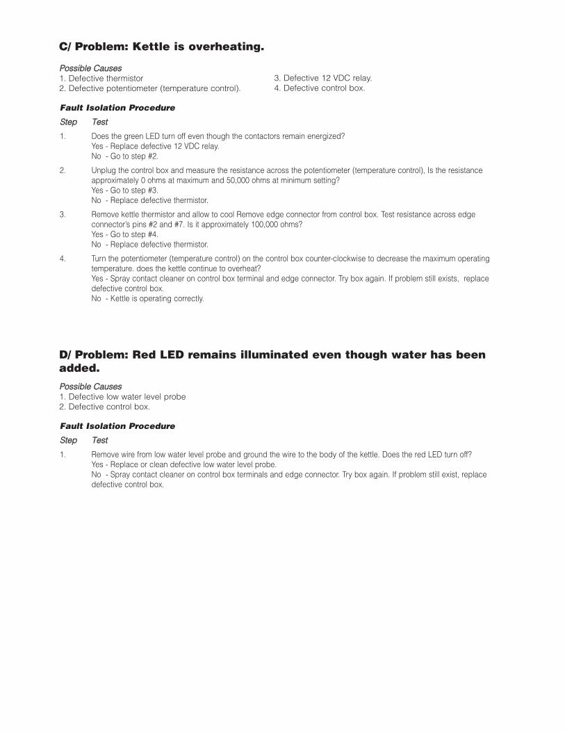
C/ Problem: Kettle is overheating.
Fault Isolation Procedure
SStteepp TTeesstt
1. Does the green LED turn off even though the contactors remain energized?Yes - Replace defective 12 VDC relay.No - Go to step #2.
2. Unplug the control box and measure the resistance across the potentiometer (temperature control), Is the resistanceapproximately 0 ohms at maximum and 50,000 ohms at minimum setting?Yes - Go to step #3.No - Replace defective thermistor.
3. Remove kettle thermistor and allow to cool Remove edge connector from control box. Test resistance across edgeconnector’s pins #2 and #7. Is it approximately 100,000 ohms?Yes - Go to step #4.No - Replace defective thermistor.
4. Turn the potentiometer (temperature control) on the control box counter-clockwise to decrease the maximum operatingtemperature. does the kettle continue to overheat?Yes - Spray contact cleaner on control box terminal and edge connector. Try box again. If problem still exists, replacedefective control box.No - Kettle is operating correctly.
PPoossssiibbllee CCaauusseess1. Defective low water level probe2. Defective control box.
D/ Problem: Red LED remains illuminated even though water has beenadded.
Fault Isolation Procedure
SStteepp TTeesstt
1. Remove wire from low water level probe and ground the wire to the body of the kettle. Does the red LED turn off?Yes - Replace or clean defective low water level probe.No - Spray contact cleaner on control box terminals and edge connector. Try box again. If problem still exist, replacedefective control box.
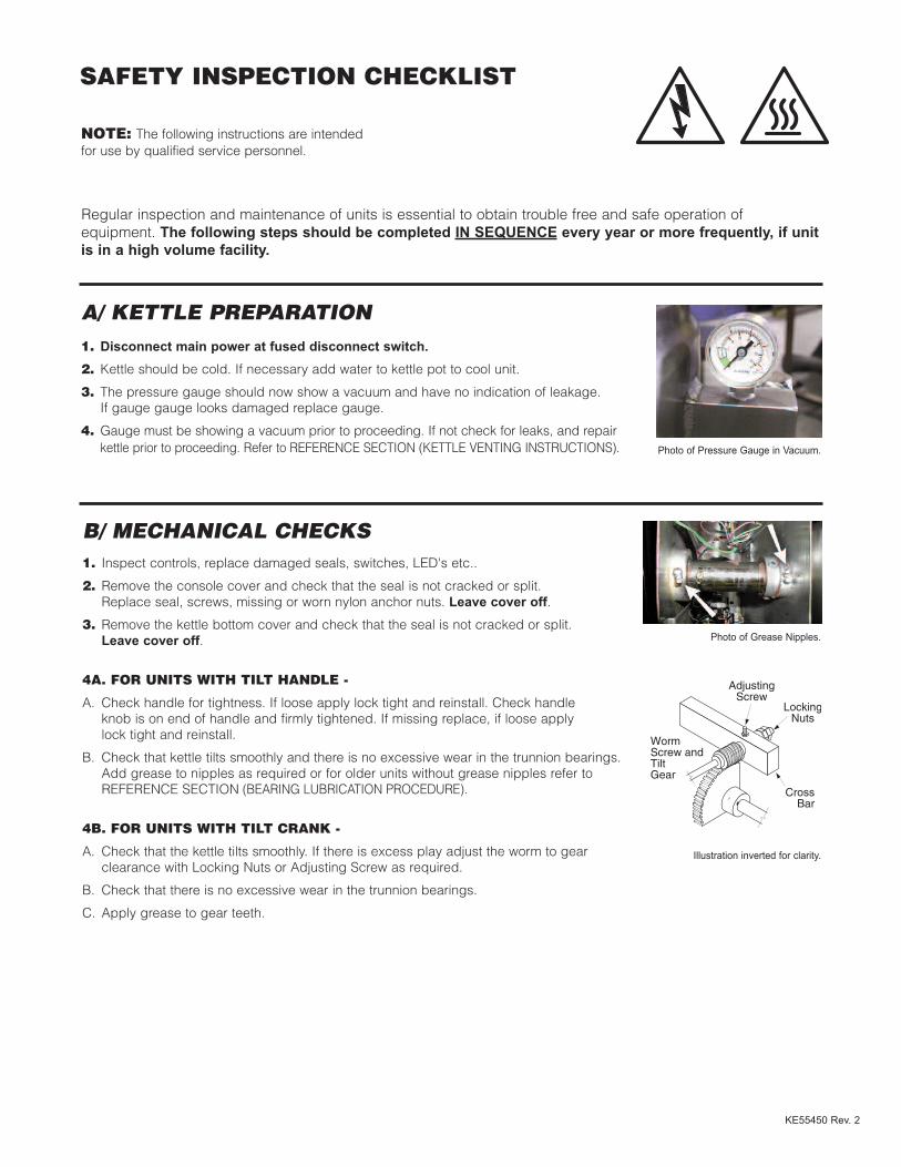
B/ MECHANICAL CHECKS1. Inspect controls, replace damaged seals, switches, LED's etc..
2. Remove the console cover and check that the seal is not cracked or split. Replace seal, screws, missing or worn nylon anchor nuts. Leave cover off.
3. Remove the kettle bottom cover and check that the seal is not cracked or split. Leave cover off.
4A. FOR UNITS WITH TILT HANDLE -
A. Check handle for tightness. If loose apply lock tight and reinstall. Check handle knob is on end of handle and firmly tightened. If missing replace, if loose apply lock tight and reinstall.
B. Check that kettle tilts smoothly and there is no excessive wear in the trunnion bearings. Add grease to nipples as required or for older units without grease nipples refer to REFERENCE SECTION (BEARING LUBRICATION PROCEDURE).
4B. FOR UNITS WITH TILT CRANK -
A. Check that the kettle tilts smoothly. If there is excess play adjust the worm to gear clearance with Locking Nuts or Adjusting Screw as required.
B. Check that there is no excessive wear in the trunnion bearings.
C. Apply grease to gear teeth.
SAFETY INSPECTION CHECKLIST
NOTE: The following instructions are intended for use by qualified service personnel.
KE55450 Rev. 2
Regular inspection and maintenance of units is essential to obtain trouble free and safe operation ofequipment. The following steps should be completed IN SEQUENCE every year or more frequently, if unitis in a high volume facility.
A/ KETTLE PREPARATION1. Disconnect main power at fused disconnect switch.2. Kettle should be cold. If necessary add water to kettle pot to cool unit.
3. The pressure gauge should now show a vacuum and have no indication of leakage. If gauge gauge looks damaged replace gauge.
4. Gauge must be showing a vacuum prior to proceeding. If not check for leaks, and repair kettle prior to proceeding. Refer to REFERENCE SECTION (KETTLE VENTING INSTRUCTIONS).
AdjustingScrew
WormScrew andTiltGear
CrossBar
LockingNuts
Illustration inverted for clarity.
Photo of Grease Nipples.
Photo of Pressure Gauge in Vacuum.
0
!
0
!
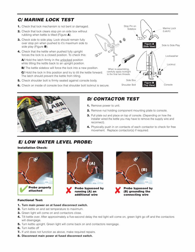
E/ LOW WATER LEVEL PROBE:
Probe bypassed byrunning (A) anadditional wire
Probe properlyattached� � Probe bypassed by
(B) grounding theconnecting wire
�
(A)
(B)
D/ CONTACTOR TEST1. Remove power to unit.
2. Remove nut holding component mounting plate to console.
3. Pull plate out and place on top of console. (Depending on how theinstaller wired the kettle you may have to remove the supply wire andreconnect).
4. Physically push in on contacts of each contactor to check for freemovement. Replace contactor(s) if required.
C/ MARINE LOCK TEST1. Check that lock mechanism is not bent or damaged.
2. Check that lock clears stop pin on side box withoutrubbing when kettle is tilted (Figure A).
3. Check side to side play. Lock should remain fullyover stop pin when pushed to it's maximum side toside play (Figure B).
4. Check that the kettle when pushed fully upright forces the lock to a closed position. To check this:
A/ Hold the latch firmly in the unlocked positionwhile tilting the kettle back to an upright position.
B/ The kettle sidebox will force the lock into a new position.
C/ Hold the lock in this position and try to tilt the kettle forward. The latch should prevent the kettle from tilting.
5. Check shoulder bolt is firmly seated against console body.
6. Check on inside of console box that shoulder bolt locknut is secure.
Side Box
Lockwasher
Locknut
Shoulder Bolt ConsoleFigure B(Top View)
Side to Side Play
Stop Pin onSidebox Marine Lock
(Latch)
Figure A(Side View)
Functional Test:
1. Turn main power on at fused disconnect switch.2. Turn kettle on and set temperature to maximum.3. Green light will come on and contactors close.4. Tilt kettle over. After approximately a five-second delay the red light will come on, green light go off and the contactorswill disengage.
5. Turn kettle upright. Green light will come back on and contactors reengage.6. Turn kettle off7. If unit does not function as above, make required repairs.8. Disconnect main power at fused disconnect switch.
Installation Check:
When re-assembling,carefully apply locktightto the final two threads.
8Plug
8Tube diameter reduced
8Plumbed to drain or water line
1
2
3
44
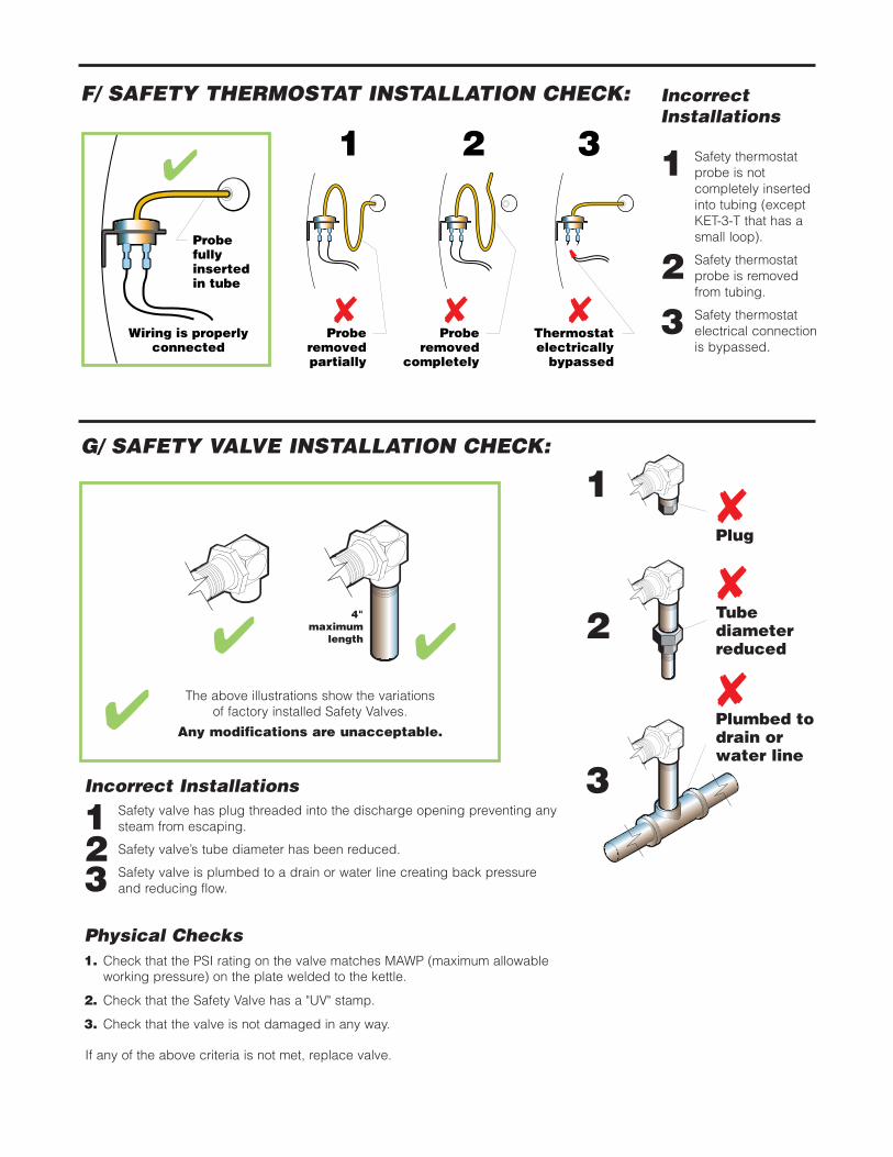
Incorrect Installations
1 Safety valve has plug threaded into the discharge opening preventing anysteam from escaping.
2 Safety valve’s tube diameter has been reduced.
3 Safety valve is plumbed to a drain or water line creating back pressureand reducing flow.
Physical Checks1. Check that the PSI rating on the valve matches MAWP (maximum allowableworking pressure) on the plate welded to the kettle.
2. Check that the Safety Valve has a "UV" stamp.
3. Check that the valve is not damaged in any way.
If any of the above criteria is not met, replace valve.
G/ SAFETY VALVE INSTALLATION CHECK:
The above illustrations show the variations of factory installed Safety Valves.
Any modifications are unacceptable.�
F/ SAFETY THERMOSTAT INSTALLATION CHECK:
8 Probe
removed partially
8 Probe
removed completely
8 Thermostat electrically
bypassed
4
Probe fully inserted in tube
Wiring is properly connected
1 2 3
IncorrectInstallations
1 Safety thermostatprobe is notcompletely insertedinto tubing (exceptKET-3-T that has asmall loop).
2 Safety thermostatprobe is removedfrom tubing.
3 Safety thermostatelectrical connectionis bypassed.
4"maximum
length
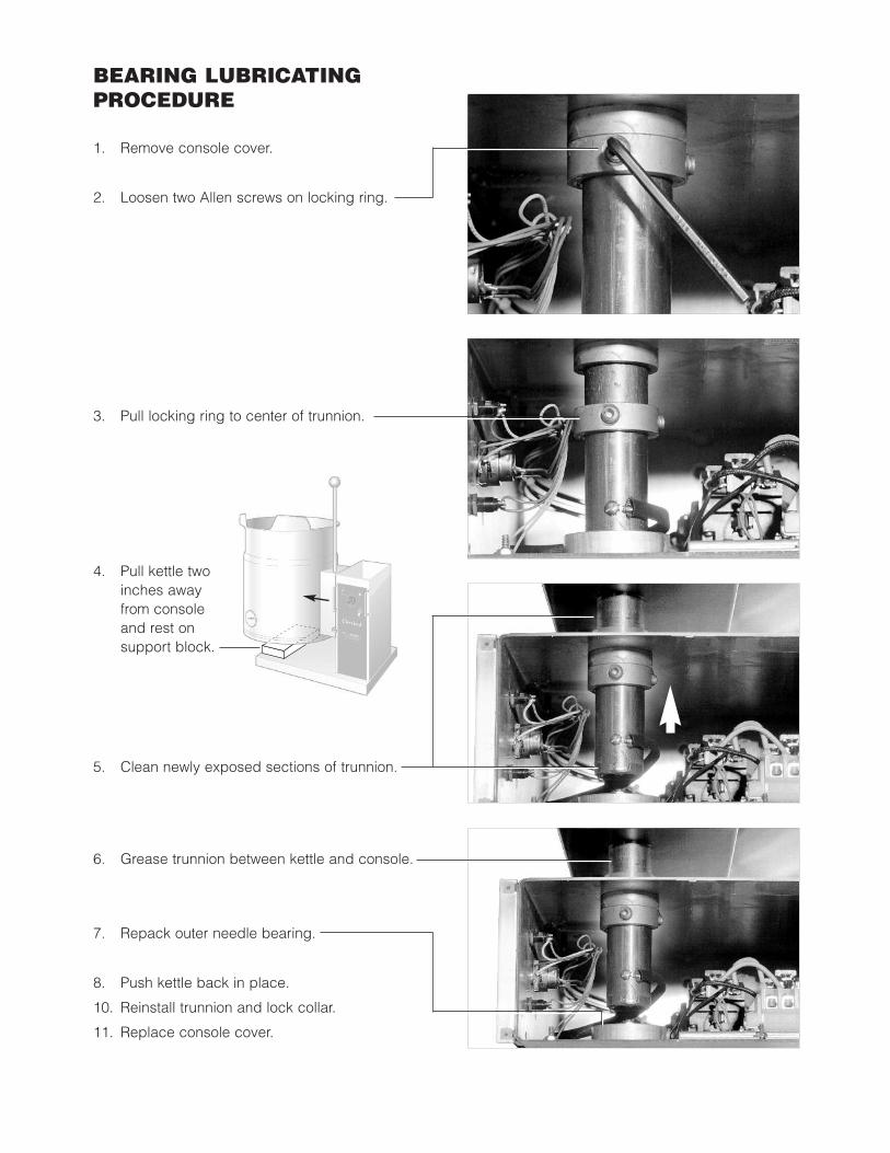
BEARING LUBRICATINGPROCEDURE
1. Remove console cover.
2. Loosen two Allen screws on locking ring.
3. Pull locking ring to center of trunnion.
5. Clean newly exposed sections of trunnion.
6. Grease trunnion between kettle and console.
7. Repack outer needle bearing.
8. Push kettle back in place.
10. Reinstall trunnion and lock collar.
11. Replace console cover.
4. Pull kettle twoinches awayfrom consoleand rest onsupport block.
CALIBRATING PROCEDURE
1. Kettle must be empty when this procedure is executed.
2. Insure the unit has a vacuum before you begincalibrating procedures. If unit requires venting refer toKETTLE VENTING INSTRUCTIONS.
3. Set On-Off Switch/Temperature Control to "10" (Max.).
4. Allow the unit to cycle twice.
5. Check temperature of the inner kettle surface with adigital surface thermometer.
6. Temperature should be between 260° F and 265° F.
7. Using a screw driver adjust temperature by turning thepotentiometer on the black box. Turn very little. Turnclockwise to INCREASES and counter-clockwise toDECREASE temperature.
8. Allow the unit to cycle twice.
9. Check temperature of the inner kettle surface with adigital surface thermometer.
10. Repeat steps 5. through 9. until unit is calibrated.).
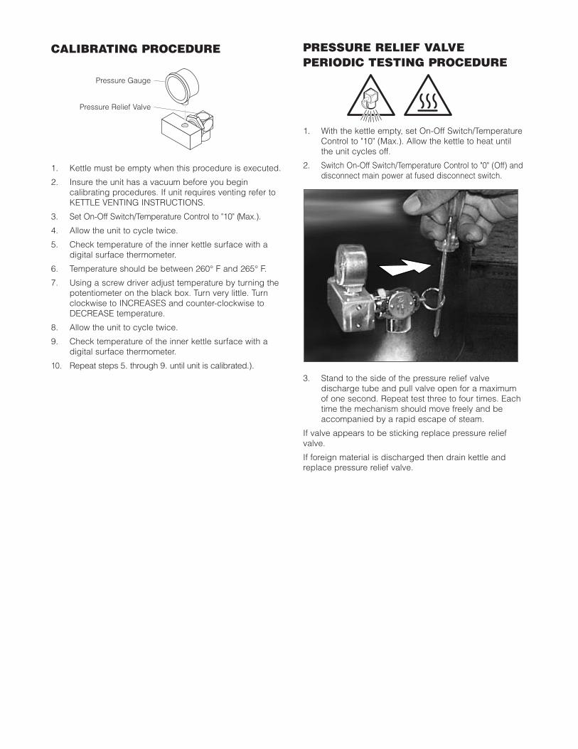
PRESSURE RELIEF VALVEPERIODIC TESTING PROCEDURE
1. With the kettle empty, set On-Off Switch/TemperatureControl to "10" (Max.). Allow the kettle to heat untilthe unit cycles off.
2. Switch On-Off Switch/Temperature Control to "0" (Off) anddisconnect main power at fused disconnect switch.
3. Stand to the side of the pressure relief valvedischarge tube and pull valve open for a maximumof one second. Repeat test three to four times. Eachtime the mechanism should move freely and beaccompanied by a rapid escape of steam.
If valve appears to be sticking replace pressure reliefvalve.
If foreign material is discharged then drain kettle andreplace pressure relief valve.
PressureGauge
PressureReliefValve
Pressure Gauge
Pressure Relief Valve
0
0
0
0
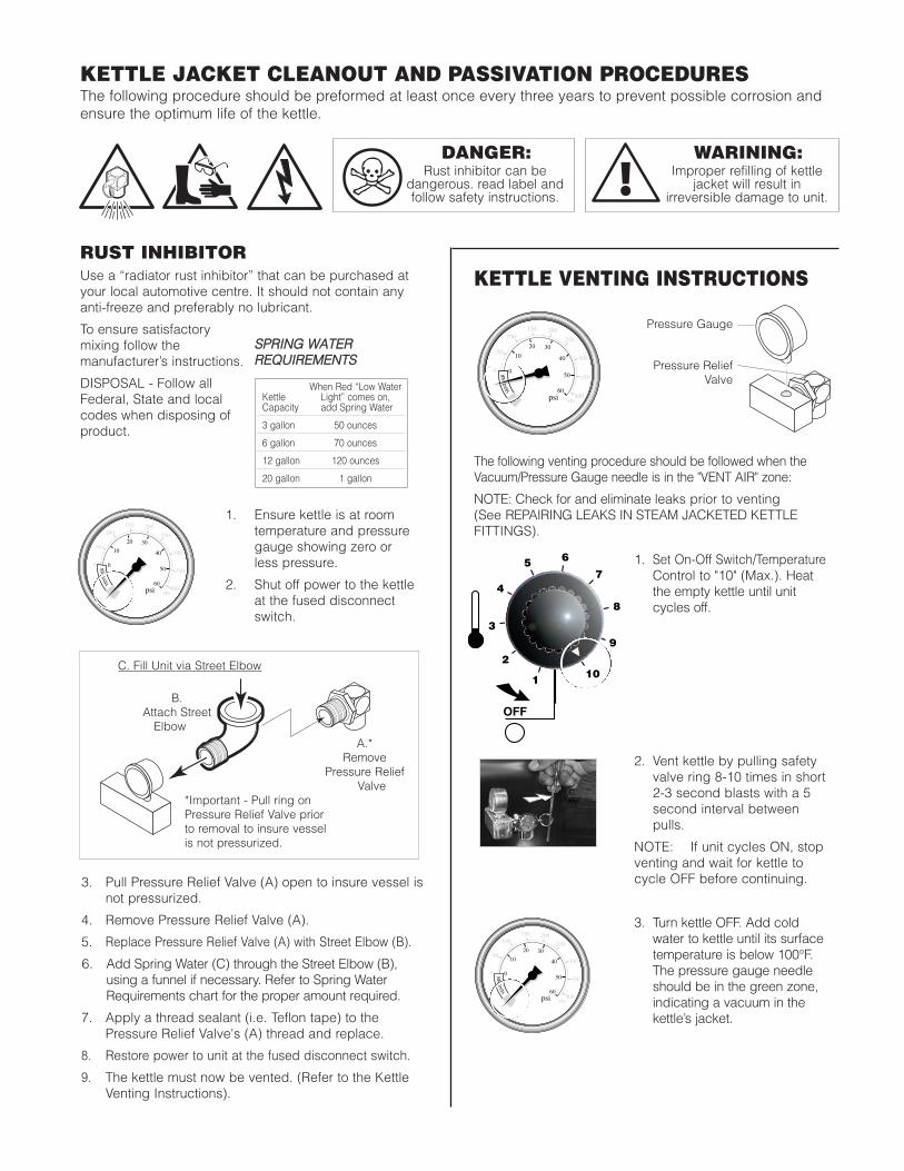
3. Pull Pressure Relief Valve (A) open to insure vessel isnot pressurized.
4. Remove Pressure Relief Valve (A).
5. Replace Pressure Relief Valve (A) with Street Elbow (B).
6. Add Spring Water (C) through the Street Elbow (B),using a funnel if necessary. Refer to Spring WaterRequirements chart for the proper amount required.
7. Apply a thread sealant (i.e. Teflon tape) to thePressure Relief Valve's (A) thread and replace.
8. Restore power to unit at the fused disconnect switch.
9. The kettle must now be vented. (Refer to the KettleVenting Instructions).
KETTLE VENTING INSTRUCTIONS
1. Ensure kettle is at roomtemperature and pressuregauge showing zero orless pressure.
2. Shut off power to the kettleat the fused disconnectswitch.
1. Set On-Off Switch/TemperatureControl to "10" (Max.). Heatthe empty kettle until unitcycles off.
2. Vent kettle by pulling safetyvalve ring 8-10 times in short2-3 second blasts with a 5second interval betweenpulls.
NOTE: If unit cycles ON, stopventing and wait for kettle tocycle OFF before continuing.
3. Turn kettle OFF. Add coldwater to kettle until its surfacetemperature is below 100°F.The pressure gauge needleshould be in the green zone,indicating a vacuum in thekettle’s jacket.
2
3
5 6
7
8
9
1
4
10
OFF
50
0
100150 200
250
300
350
400
40
50
60
0
10
20 30
psi kPa
VEN
TAI
R
50
0
100150 200
250
300
350
400
40
50
60
0
10
20 30
psi kPa
VEN
TAI
R
50
0
100150 200
250
300
350
400
40
50
60
0
10
20 30
psi kPa
VEN
TAI
R50
0
100150 200
250
300
350
400
40
50
60
0
10
20 30
psi kPa
VEN
TAI
R
50
0
100150 200
250
300
350
400
40
50
60
0
10
20 30
psi kPa
VEN
TAI
R
50
0
100150 200
250
300
350
400
40
50
60
0
10
20 30
psi kPa
VEN
TAI
R
50
0
100150 200
250
300
350
400
40
50
60
0
10
20 30
psi kPa
VEN
TAI
R
50
0
100150 200
250
300
350
400
40
50
60
0
10
20 30
psi kPa
VEN
TAI
R
50
0
100150 200
250
300
350
400
40
50
60
0
10
20 30
psi kPa
VEN
TAI
R
The following venting procedure should be followed when theVacuum/Pressure Gauge needle is in the "VENT AIR" zone:
NOTE: Check for and eliminate leaks prior to venting(See REPAIRING LEAKS IN STEAM JACKETED KETTLEFITTINGS).
A.* RemovePressure
ReliefValve
B. Attach Street
Elbow
C. Fill unit via Street Elbow
*Important- Pull ring on Pressure Relief Valve prior to removal to insure vessel is not pressurized.
PressureGauge
PressureReliefValve
Pressure Gauge
Pressure ReliefValve
C. Fill Unit via Street Elbow
B. Attach StreetElbow
A.*Remove
Pressure ReliefValve
*Important - Pull ring onPressure Relief Valve priorto removal to insure vesselis not pressurized.
KETTLE JACKET CLEANOUT AND PASSIVATION PROCEDURESThe following procedure should be preformed at least once every three years to prevent possible corrosion andensure the optimum life of the kettle.
DANGER:Rust inhibitor can be
dangerous. read label andfollow safety instructions.
0
!
RUST INHIBITORUse a “radiator rust inhibitor” that can be purchased atyour local automotive centre. It should not contain anyanti-freeze and preferably no lubricant.
To ensure satisfactorymixing follow themanufacturer’s instructions.
DISPOSAL - Follow allFederal, State and localcodes when disposing ofproduct.
WARINING:Improper refilling of kettle
jacket will result in irreversible damage to unit.
0
!
SSPPRRIINNGG WWAATTEERR RREEQQUUIIRREEMMEENNTTSS
When Red “Low WaterKettle Light” comes on, Capacity add Spring Water
3 gallon 50 ounces
6 gallon 70 ounces
12 gallon 120 ounces
20 gallon 1 gallon
0
0
0
0
0
0
VACUUM LEAKSIf unit will not hold a vacuum the most likely cause is aleak at one of the fittings.Often, the easiest way to eliminate a leak is reseal thesuspect areas.
1. Water Level Probe
Remove, clean threads, apply teflon thread sealantand reinstall.
2 Pressure Relief Valve
A/ Inspect for signs of leaks. Replace if required.
B/ Remove, clean threads, apply teflon threadsealant and reinstall.
3. Pressure Gauge
A/ Inspect face of gauge. If it contains moisture onthe inside of face replace.
B/ Remove, clean threads, apply teflon threadsealant and reinstall.
I leak persists replace all three components at sametime.
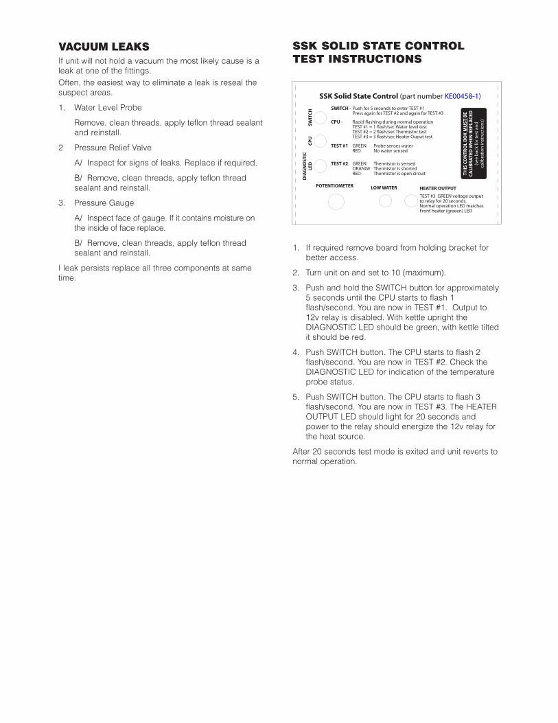
1. If required remove board from holding bracket forbetter access.
2. Turn unit on and set to 10 (maximum).
3. Push and hold the SWITCH button for approximately5 seconds until the CPU starts to flash 1flash/second. You are now in TEST #1. Output to12v relay is disabled. With kettle upright theDIAGNOSTIC LED should be green, with kettle tiltedit should be red.
4. Push SWITCH button. The CPU starts to flash 2flash/second. You are now in TEST #2. Check theDIAGNOSTIC LED for indication of the temperatureprobe status.
5. Push SWITCH button. The CPU starts to flash 3flash/second. You are now in TEST #3. The HEATEROUTPUT LED should light for 20 seconds andpower to the relay should energize the 12v relay forthe heat source.
After 20 seconds test mode is exited and unit reverts tonormal operation.
THIS
CO
NTR
OL
BOX
MU
ST B
ECA
LIBR
ATED
WH
EN R
EPLA
CED
(see
bac
k fo
r tes
t and
calib
ratio
n in
stru
ctio
ns)
SSK Solid State Control (part number KE00458-1)
DIA
GN
OST
ICLE
D
SWIT
CH
CPU
SWITCH - Push for 5 seconds to enter TEST #1 Press again for TEST #2 and again for TEST #3
CPU - Rapid !ashing during normal operation TEST #1 = 1 !ash/sec Water level test TEST #2 = 2 !ash/sec Thermistor test TEST #3 = 3 !ash/sec Heater Ouput test TEST #1 GREEN Probe senses water RED No water sensed
TEST #2 GREEN Thermistor is sensed ORANGE Thermistor is shorted RED Thermistor is open circuit
POTENTIOMETER LOW WATER HEATER OUTPUT
TEST #3 GREEN voltage output to relay for 20 seconds.Normal operation LED matches Front heater (greeen) LED
SSK SOLID STATE CONTROLTEST INSTRUCTIONS
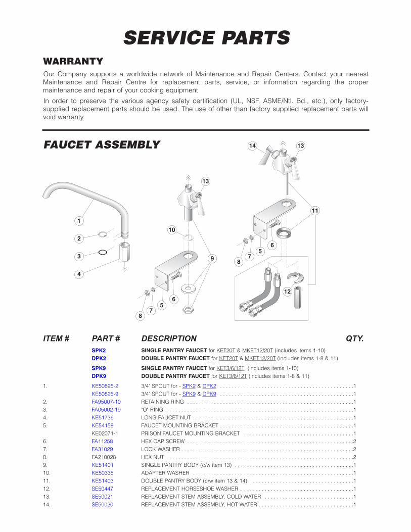
SERVICE PARTSWARRANTYOur Company supports a worldwide network of Maintenance and Repair Centers. Contact your nearestMaintenance and Repair Centre for replacement parts, service, or information regarding the propermaintenance and repair of your cooking equipment
In order to preserve the various agency safety certification (UL, NSF, ASME/Ntl. Bd., etc.), only factory-supplied replacement parts should be used. The use of other than factory supplied replacement parts willvoid warranty.
ITEM # PART # DESCRIPTION QTY.SPK2 SINGLE PANTRY FAUCET for KET20T & MKET12/20T (includes items 1-10)DPK2 DOUBLE PANTRY FAUCET for KET20T & MKET12/20T (includes items 1-8 & 11)
SPK9 SINGLE PANTRY FAUCET for KET3/6/12T (includes items 1-10)DPK9 DOUBLE PANTRY FAUCET for KET3/6/12T (includes items 1-8 & 11)
1. KE50825-2 3/4" SPOUT for - SPK2 & DPK2 . . . . . . . . . . . . . . . . . . . . . . . . . . . . . . . . . . . . . . . . . . . . .1 KE50825-9 3/4" SPOUT for - SPK9 & DPK9 . . . . . . . . . . . . . . . . . . . . . . . . . . . . . . . . . . . . . . . . . . . . .1
2. FA95007-10 RETAINING RING . . . . . . . . . . . . . . . . . . . . . . . . . . . . . . . . . . . . . . . . . . . . . . . . . . . . . . . .1 3. FA05002-19 "O" RING . . . . . . . . . . . . . . . . . . . . . . . . . . . . . . . . . . . . . . . . . . . . . . . . . . . . . . . . . . . . . . .1 4. KE51736 LONG FAUCET NUT . . . . . . . . . . . . . . . . . . . . . . . . . . . . . . . . . . . . . . . . . . . . . . . . . . . . . .1 5. KE54159 FAUCET MOUNTING BRACKET . . . . . . . . . . . . . . . . . . . . . . . . . . . . . . . . . . . . . . . . . . . . .1
KE02071-1 PRISON FAUCET MOUNTING BRACKET . . . . . . . . . . . . . . . . . . . . . . . . . . . . . . . . . . . . .1 6. FA11258 HEX CAP SCREW . . . . . . . . . . . . . . . . . . . . . . . . . . . . . . . . . . . . . . . . . . . . . . . . . . . . . . . .2 7. FA31029 LOCK WASHER . . . . . . . . . . . . . . . . . . . . . . . . . . . . . . . . . . . . . . . . . . . . . . . . . . . . . . . . . .2 8. FA210028 HEX NUT . . . . . . . . . . . . . . . . . . . . . . . . . . . . . . . . . . . . . . . . . . . . . . . . . . . . . . . . . . . . . . .29. KE51401 SINGLE PANTRY BODY (c/w item 13) . . . . . . . . . . . . . . . . . . . . . . . . . . . . . . . . . . . . . . . .1 10. KE50335 ADAPTER WASHER . . . . . . . . . . . . . . . . . . . . . . . . . . . . . . . . . . . . . . . . . . . . . . . . . . . . . .1 11. KE51403 DOUBLE PANTRY BODY (c/w item 13 & 14) . . . . . . . . . . . . . . . . . . . . . . . . . . . . . . . . . .1 12. SE50447 REPLACEMENT HORSESHOE WASHER . . . . . . . . . . . . . . . . . . . . . . . . . . . . . . . . . . . . . .113. SE50021 REPLACEMENT STEM ASSEMBLY, COLD WATER . . . . . . . . . . . . . . . . . . . . . . . . . . . . . .1 14. SE50020 REPLACEMENT STEM ASSEMBLY, HOT WATER . . . . . . . . . . . . . . . . . . . . . . . . . . . . . . . .1
FAUCET ASSEMBLY
1
9
11
10
13
1314
12
65
78
65
78
2
3
4
1
9
11
13
1314
12
78
2
3
4
1 9
11
13 13 15
16
17
18
19
14 14 13
12
2
3
4
SPOUT(for Standard & Remote Faucets)
STANDARD FAUCET(Single & Double Pantry for SD or STD Stands)
REMOTE FAUCET(Double Pantry for SD Stands)
20
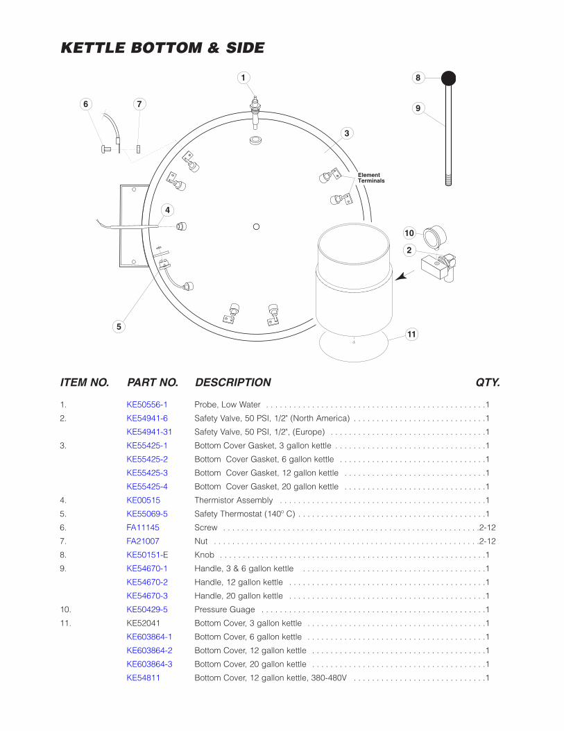
KETTLE BOTTOM & SIDE
ITEM NO. PART NO. DESCRIPTION QTY.
1. KE50556-1 Probe, Low Water . . . . . . . . . . . . . . . . . . . . . . . . . . . . . . . . . . . . . . . . . . . . . . . .1
2. KE54941-6 Safety Valve, 50 PSI, 1/2" (North America) . . . . . . . . . . . . . . . . . . . . . . . . . . . . .1
KE54941-31 Safety Valve, 50 PSI, 1/2", (Europe) . . . . . . . . . . . . . . . . . . . . . . . . . . . . . . . . . .1
3. KE55425-1 Bottom Cover Gasket, 3 gallon kettle . . . . . . . . . . . . . . . . . . . . . . . . . . . . . . . . .1
KE55425-2 Bottom Cover Gasket, 6 gallon kettle . . . . . . . . . . . . . . . . . . . . . . . . . . . . . . . .1
KE55425-3 Bottom Cover Gasket, 12 gallon kettle . . . . . . . . . . . . . . . . . . . . . . . . . . . . . . .1
KE55425-4 Bottom Cover Gasket, 20 gallon kettle . . . . . . . . . . . . . . . . . . . . . . . . . . . . . . .1
4. KE00515 Thermistor Assembly . . . . . . . . . . . . . . . . . . . . . . . . . . . . . . . . . . . . . . . . . . . . .1
5. KE55069-5 Safety Thermostat (140º C) . . . . . . . . . . . . . . . . . . . . . . . . . . . . . . . . . . . . . . . . .1
6. FA11145 Screw . . . . . . . . . . . . . . . . . . . . . . . . . . . . . . . . . . . . . . . . . . . . . . . . . . . . . . . .2-12
7. FA21007 Nut . . . . . . . . . . . . . . . . . . . . . . . . . . . . . . . . . . . . . . . . . . . . . . . . . . . . . . . . . .2-12
8. KE50151-E Knob . . . . . . . . . . . . . . . . . . . . . . . . . . . . . . . . . . . . . . . . . . . . . . . . . . . . . . . . . .1
9. KE54670-1 Handle, 3 & 6 gallon kettle . . . . . . . . . . . . . . . . . . . . . . . . . . . . . . . . . . . . . . . .1
KE54670-2 Handle, 12 gallon kettle . . . . . . . . . . . . . . . . . . . . . . . . . . . . . . . . . . . . . . . . . . .1
KE54670-3 Handle, 20 gallon kettle . . . . . . . . . . . . . . . . . . . . . . . . . . . . . . . . . . . . . . . . . . .1
10. KE50429-5 Pressure Guage . . . . . . . . . . . . . . . . . . . . . . . . . . . . . . . . . . . . . . . . . . . . . . . . .1
11. KE52041 Bottom Cover, 3 gallon kettle . . . . . . . . . . . . . . . . . . . . . . . . . . . . . . . . . . . . . . .1
KE603864-1 Bottom Cover, 6 gallon kettle . . . . . . . . . . . . . . . . . . . . . . . . . . . . . . . . . . . . . . .1
KE603864-2 Bottom Cover, 12 gallon kettle . . . . . . . . . . . . . . . . . . . . . . . . . . . . . . . . . . . . . .1
KE603864-3 Bottom Cover, 20 gallon kettle . . . . . . . . . . . . . . . . . . . . . . . . . . . . . . . . . . . . . .1
KE54811 Bottom Cover, 12 gallon kettle, 380-480V . . . . . . . . . . . . . . . . . . . . . . . . . . . . .1
6 7
1 8
9
4
ElementTerminals
3
115
2
10
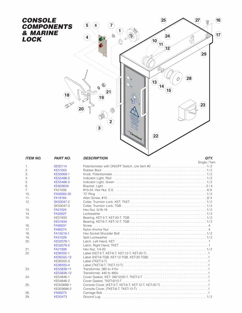
ITEM NO. PART NO. DESCRIPTION QTY.Single / Twin
1. SE00114 Potentiometer with ON/OFF Switch, c/w Item #2 . . . . . . . . . . . . . . . . . . . . . . . . . . . . . . . 1 / 22. KE51005 Rubber Boot . . . . . . . . . . . . . . . . . . . . . . . . . . . . . . . . . . . . . . . . . . . . . . . . . . . . . . . . . . . 1 / 23. KE50569-1 Knob, Potentiometer . . . . . . . . . . . . . . . . . . . . . . . . . . . . . . . . . . . . . . . . . . . . . . . . . . . . . 1 / 24. KE55486-2 Indicator Light, Red . . . . . . . . . . . . . . . . . . . . . . . . . . . . . . . . . . . . . . . . . . . . . . . . . . . . 1 / 25. KE55486-3 Indicator Light, Green . . . . . . . . . . . . . . . . . . . . . . . . . . . . . . . . . . . . . . . . . . . . . . . . . . . 1 / 26. KE603634 Bracket, Light . . . . . . . . . . . . . . . . . . . . . . . . . . . . . . . . . . . . . . . . . . . . . . . . . . . . . . . . . . 2 / 47. FA21006 #10-24, Hex Nut, S.S. . . . . . . . . . . . . . . . . . . . . . . . . . . . . . . . . . . . . . . . . . . . . . . . . . . . . 4/ 810. FA05002-20 "O" Ring . . . . . . . . . . . . . . . . . . . . . . . . . . . . . . . . . . . . . . . . . . . . . . . . . . . . . . . . . . . . . . 1 / 211. FA19184 Allen Screw, #10 . . . . . . . . . . . . . . . . . . . . . . . . . . . . . . . . . . . . . . . . . . . . . . . . . . . . . . . . 2/ 412. SK50047-2 Collar, Trunnion Lock, KET, TKET . . . . . . . . . . . . . . . . . . . . . . . . . . . . . . . . . . . . . . . . . . . 1 / 2
SK50047-3 Collar, Trunnion Lock, TGB . . . . . . . . . . . . . . . . . . . . . . . . . . . . . . . . . . . . . . . . . . . . . . . . 1 / 213. FA21024 Hex Nut, 5/16-18 . . . . . . . . . . . . . . . . . . . . . . . . . . . . . . . . . . . . . . . . . . . . . . . . . . . . . . . 1 / 214. FA32027 Lockwasher . . . . . . . . . . . . . . . . . . . . . . . . . . . . . . . . . . . . . . . . . . . . . . . . . . . . . . . . . . . 1 / 215. KE01833 Bearing, KET-3-T, KET-20-T, TGB . . . . . . . . . . . . . . . . . . . . . . . . . . . . . . . . . . . . . . . . . . . 1 / 2
KE01834 Bearing, KET-6-T, KET-12-T, TGB . . . . . . . . . . . . . . . . . . . . . . . . . . . . . . . . . . . . . . . . . . . 1 / 216. FA95031 Screw . . . . . . . . . . . . . . . . . . . . . . . . . . . . . . . . . . . . . . . . . . . . . . . . . . . . . . . . . . . . . . . . . 417. FA95074 Nylon Anchor Nut . . . . . . . . . . . . . . . . . . . . . . . . . . . . . . . . . . . . . . . . . . . . . . . . . . . . . . . . 418. FA15019-1 Hex Socket Shoulder Bolt . . . . . . . . . . . . . . . . . . . . . . . . . . . . . . . . . . . . . . . . . . . . . . . . 1 / 219. FA31029 Split Lockwasher . . . . . . . . . . . . . . . . . . . . . . . . . . . . . . . . . . . . . . . . . . . . . . . . . . . . . . . 1 / 220. KE02078-1 Latch, Left Hand, KET . . . . . . . . . . . . . . . . . . . . . . . . . . . . . . . . . . . . . . . . . . . . . . . . . . . . 1
KE02078-2 Latch, Right Hand, TKET . . . . . . . . . . . . . . . . . . . . . . . . . . . . . . . . . . . . . . . . . . . . . . . . . . 121. FA21008 Hex Nut, 1/4-20 . . . . . . . . . . . . . . . . . . . . . . . . . . . . . . . . . . . . . . . . . . . . . . . . . . . . . . . . 1 / 222. KE95555-1 Label (KET-3-T, KET-6-T, KET-12-T, KET-20-T) . . . . . . . . . . . . . . . . . . . . . . . . . . . . . . . . . . .1
KE95555-12 Label (KET-6-TGB, KET-12-TGB, KET-20-TGB) . . . . . . . . . . . . . . . . . . . . . . . . . . . . . . . . .1KE95555-3 Label (TKET-3-T) . . . . . . . . . . . . . . . . . . . . . . . . . . . . . . . . . . . . . . . . . . . . . . . . . . . . . .1KE95555-4 Label (TKET-6-T, TKET-12-T) . . . . . . . . . . . . . . . . . . . . . . . . . . . . . . . . . . . . . . . . . . . . . . . .1
23. KE53838-11 Transformer, 380 to 415v . . . . . . . . . . . . . . . . . . . . . . . . . . . . . . . . . . . . . . . . . . . . . . . . . .1KE53838-12 Transformer, 440 to 480v . . . . . . . . . . . . . . . . . . . . . . . . . . . . . . . . . . . . . . . . . . . . . . . . . .1
24. KE54846-1 Cover Gasket, KET- 3/6/12/20-T, TKET-3-T . . . . . . . . . . . . . . . . . . . . . . . . . . . . . . . . . . . . .1KE54846-2 Cover Gasket, TKET-6/12-T . . . . . . . . . . . . . . . . . . . . . . . . . . . . . . . . . . . . . . . . . . . . . . . . .1
25. KE003688-1 Console Cover, (KET-3-T, KET-6-T, KET-12-T, KET-20-T) . . . . . . . . . . . . . . . . . . . . . . . . . . .1KE003688-2 Console Cover, (TKET-6-T, TKET-12-T) . . . . . . . . . . . . . . . . . . . . . . . . . . . . . . . . . . . . . . . .1
28. FA95073 Carriage Bolt . . . . . . . . . . . . . . . . . . . . . . . . . . . . . . . . . . . . . . . . . . . . . . . . . . . . . . . . . . . .129. KE50473 Ground Lug . . . . . . . . . . . . . . . . . . . . . . . . . . . . . . . . . . . . . . . . . . . . . . . . . . . . . . . . . . . 1 / 2
CONSOLE COMPONENTS& MARINE LOCK
1211
10
1314
15
28
29
23
27 16
17
18 19
20
21
24
25
KE95555-1D
PUSH UPRIGHT TO LOCK
POUSSER EN POSITION
VERTICALE POUR VERROUILLERZUM SPERREN GERADE
NACH OBEN DRÜCKEN
EMPUJAR DERECHO HACIA
ARRIBA PARA BLOQUEAR
PREMERE IN ALTO PER
LA CHIUSURA
109
8
7
65
4
3
2
1OFF
23
22
5 6 7
41
TRUNNIONSHOWN
FOR CLARITY
F
6 &
12
GA
LLO
N20
GA
LLO
N
47
6
8
9
10
1133
34
5
6
9
8
14 3015
29
13
12
35A
2
APPLY RTV
SEALANT
3219B
19A
31
35B
321
28
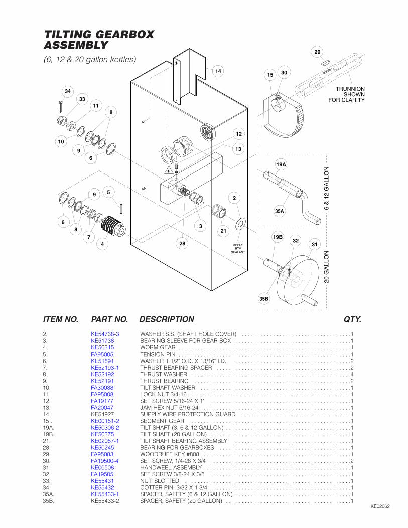
TILTING GEARBOX ASSEMBLY(6, 12 & 20 gallon kettles)
ITEM NO. PART NO. DESCRIPTION QTY.
2. KE54738-3 WASHER S.S. (SHAFT HOLE COVER) . . . . . . . . . . . . . . . . . . . . . . . . . . . . . . . . . . .13. KE51738 BEARING SLEEVE FOR GEAR BOX . . . . . . . . . . . . . . . . . . . . . . . . . . . . . . . . . . . . .14. KE50315 WORM GEAR . . . . . . . . . . . . . . . . . . . . . . . . . . . . . . . . . . . . . . . . . . . . . . . . . . . . . . .15. FA95005 TENSION PIN . . . . . . . . . . . . . . . . . . . . . . . . . . . . . . . . . . . . . . . . . . . . . . . . . . . . . . .16. KE51891 WASHER 1 1/2" O.D. X 13/16" I.D. . . . . . . . . . . . . . . . . . . . . . . . . . . . . . . . . . . . . . .27. KE52193-1 THRUST BEARING SPACER . . . . . . . . . . . . . . . . . . . . . . . . . . . . . . . . . . . . . . . . . . .28. KE52192 THRUST WASHER . . . . . . . . . . . . . . . . . . . . . . . . . . . . . . . . . . . . . . . . . . . . . . . . . . .49. KE52191 THRUST BEARING . . . . . . . . . . . . . . . . . . . . . . . . . . . . . . . . . . . . . . . . . . . . . . . . . .210. FA30088 TILT SHAFT WASHER . . . . . . . . . . . . . . . . . . . . . . . . . . . . . . . . . . . . . . . . . . . . . . . .111. FA95008 LOCK NUT 3/4-16 . . . . . . . . . . . . . . . . . . . . . . . . . . . . . . . . . . . . . . . . . . . . . . . . . . . .112. FA19177 SET SCREW 5/16-24 X 1" . . . . . . . . . . . . . . . . . . . . . . . . . . . . . . . . . . . . . . . . . . . . .113. FA20047 JAM HEX NUT 5/16-24 . . . . . . . . . . . . . . . . . . . . . . . . . . . . . . . . . . . . . . . . . . . . . . .114. KE54927 SUPPLY WIRE PROTECTION GUARD . . . . . . . . . . . . . . . . . . . . . . . . . . . . . . . . . . .115 . KE00151-2 SEGMENT GEAR . . . . . . . . . . . . . . . . . . . . . . . . . . . . . . . . . . . . . . . . . . . . . . . . . . . .119A. KE50306-2 TILT SHAFT (3, 6 & 12 GALLON) . . . . . . . . . . . . . . . . . . . . . . . . . . . . . . . . . . . . . . . .119B. KE50375 TILT SHAFT (20 GALLON) . . . . . . . . . . . . . . . . . . . . . . . . . . . . . . . . . . . . . . . . . . . . .121. KE02057-1 TILT SHAFT BEARING ASSEMBLY . . . . . . . . . . . . . . . . . . . . . . . . . . . . . . . . . . . . . .128. KE50245 BEARING FOR GEARBOXES . . . . . . . . . . . . . . . . . . . . . . . . . . . . . . . . . . . . . . . . . .129. FA95083 WOODRUFF KEY #808 . . . . . . . . . . . . . . . . . . . . . . . . . . . . . . . . . . . . . . . . . . . . . . .130. FA19500-4 SET SCREW, 1/4-28 X 3/4 . . . . . . . . . . . . . . . . . . . . . . . . . . . . . . . . . . . . . . . . . . . . .231. KE00508 HANDWEEL ASSEMBLY . . . . . . . . . . . . . . . . . . . . . . . . . . . . . . . . . . . . . . . . . . . . . .132 FA19505 SET SCREW 3/8-24 X 3/8 . . . . . . . . . . . . . . . . . . . . . . . . . . . . . . . . . . . . . . . . . . . . .133. KE55431 NUT, SLOTTED . . . . . . . . . . . . . . . . . . . . . . . . . . . . . . . . . . . . . . . . . . . . . . . . . . . . .134. KE55432 COTTER PIN, 3/32 X 1 3/4 . . . . . . . . . . . . . . . . . . . . . . . . . . . . . . . . . . . . . . . . . . . .135A. KE55433-1 SPACER, SAFETY (6 & 12 GALLON) . . . . . . . . . . . . . . . . . . . . . . . . . . . . . . . . . . . . .135B. KE55433-2 SPACER, SAFETY (20 GALLON) . . . . . . . . . . . . . . . . . . . . . . . . . . . . . . . . . . . . . . . .1
KE02062
380-400V (HIGH VOLTAGE)
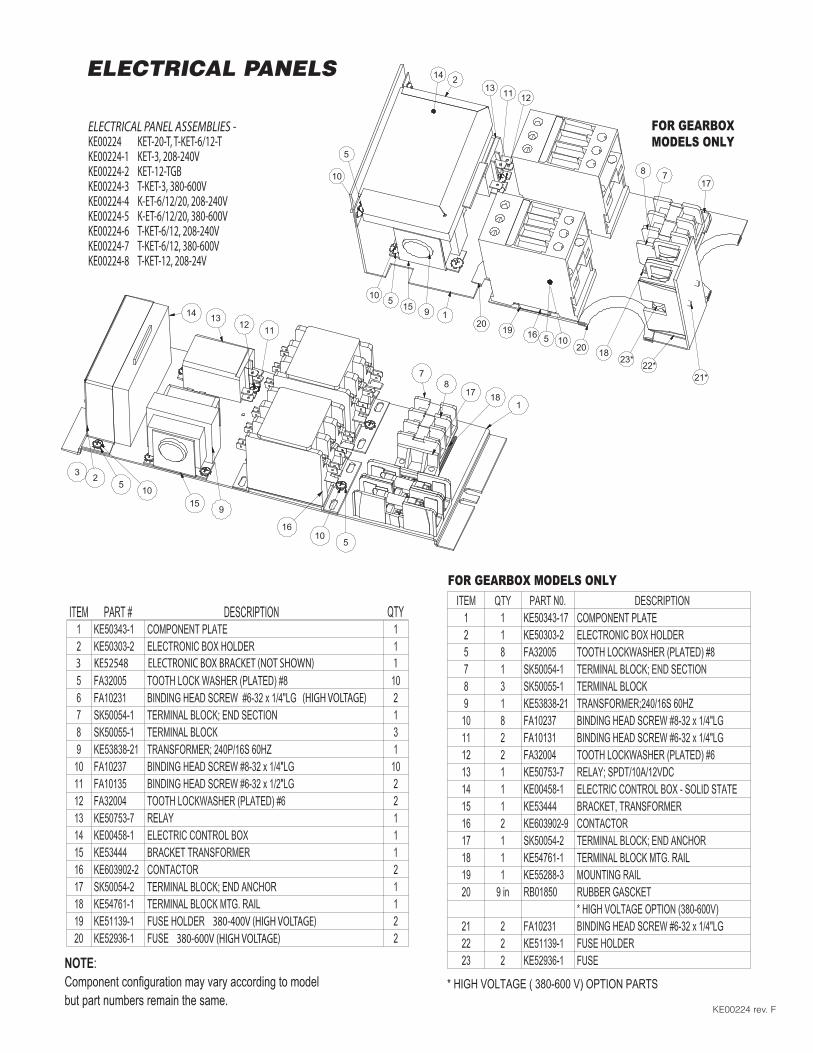
3 KE52548 ELECTRONIC BOX BRACKET (NOT SHOWN) 1
380-600V (HIGH VOLTAGE)
KE00225-2 G
(HIGH VOLTAGE)
ELECTRICAL PANEL ASSEMBLIES -KE00224 KET-20-T, T-KET-6/12-T KE00224-1 KET-3, 208-240V KE00224-2 KET-12-TGBKE00224-3 T-KET-3, 380-600VKE00224-4 K-ET-6/12/20, 208-240V KE00224-5 K-ET-6/12/20, 380-600VKE00224-6 T-KET-6/12, 208-240V KE00224-7 T-KET-6/12, 380-600VKE00224-8 T-KET-12, 208-24V
14 1312 11
78
17 181
235
1015
9
1610
5
23*22*
214
5
10
13 11 12
10 5 15 9 1
19 1620
17
18
78
105
* HIGH VOLTAGE ( 380-600 V) OPTION PARTS
FOR GEARBOX MODELS ONLY
FOR GEARBOXMODELS ONLY
20
21*
NOTE:Component configuration may vary according to model but part numbers remain the same.
ELECTRICAL PANELS
KE00224 rev. F
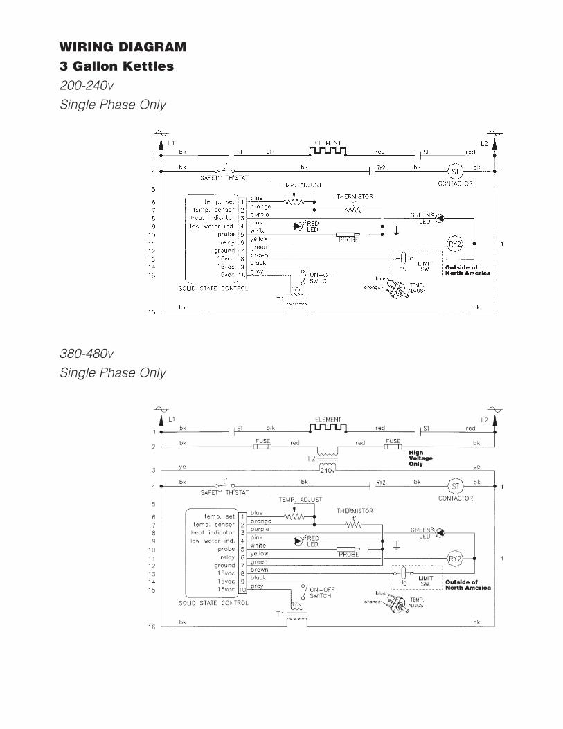
WIRING DIAGRAM3 Gallon Kettles200-240vSingle Phase Only
380-480vSingle Phase Only
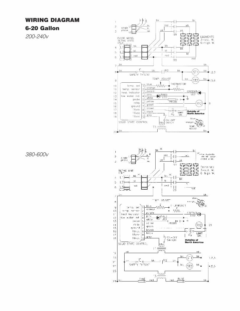
WIRING DIAGRAM6-20 Gallon200-240v
380-600v