Embed Size (px)
Citation preview
ORDERJO 6130.3
MAINTENANCE OF FLIGHT DATA INPUT/OUTPUT(FDIO) EQUIPMENT
June 1, 2006
U.S. DEPARTMENT OF TRANSPORTATIONFEDERAL AVIATION ADMINISTRATION
Distribution: 62BA, 62BB, 62BD, 62BE, 62BF Initiated By: En Route/Oceanic Services
RECORD OF CHANGES DIRECTIVE NO. JO 6130.3
CHANGETO
SUPPLEMENTSOPTIONAL
CHANGETO
SUPPLEMENTSOPTIONALTO
BASICOPTIONAL TO
BASICOPTIONAL
FAA FORM 1320--5 (6--80) USE PREVIOUS EDITION
JO 6130.306/01/06
Page iii
TABLE OF CONTENTS
Paragraph Page
Chapter 1. GENERAL INFORMATION AND REQUIREMENTS
100. Objective 1. . . . . . . . . . . . . . . . . . . . . . . . . . . . . . . . . . . . . . . . . . . . . . . . . . . . . . .101. Coordination 1. . . . . . . . . . . . . . . . . . . . . . . . . . . . . . . . . . . . . . . . . . . . . . . . . . . .102. Periodic Maintenance 1. . . . . . . . . . . . . . . . . . . . . . . . . . . . . . . . . . . . . . . . . . . .103. Interruptions Reporting 1. . . . . . . . . . . . . . . . . . . . . . . . . . . . . . . . . . . . . . . . . . .104. Standardization 1. . . . . . . . . . . . . . . . . . . . . . . . . . . . . . . . . . . . . . . . . . . . . . . . . .105. References 1. . . . . . . . . . . . . . . . . . . . . . . . . . . . . . . . . . . . . . . . . . . . . . . . . . . . .
106.--199. Reserved 1. . . . . . . . . . . . . . . . . . . . . . . . . . . . . . . . . . . . . . . . . . . . . . . . . . . . . . .
Chapter 2. TECHNICAL CHARACTERISTICS
200. General 3. . . . . . . . . . . . . . . . . . . . . . . . . . . . . . . . . . . . . . . . . . . . . . . . . . . . . . . .201. CCU 3. . . . . . . . . . . . . . . . . . . . . . . . . . . . . . . . . . . . . . . . . . . . . . . . . . . . . . . . . . .202. RCUs 4. . . . . . . . . . . . . . . . . . . . . . . . . . . . . . . . . . . . . . . . . . . . . . . . . . . . . . . . . .203. PC--RCU 5. . . . . . . . . . . . . . . . . . . . . . . . . . . . . . . . . . . . . . . . . . . . . . . . . . . . . . .204. RFSP 5. . . . . . . . . . . . . . . . . . . . . . . . . . . . . . . . . . . . . . . . . . . . . . . . . . . . . . . . . .205. RANK 5. . . . . . . . . . . . . . . . . . . . . . . . . . . . . . . . . . . . . . . . . . . . . . . . . . . . . . . . . .206. CRT 5. . . . . . . . . . . . . . . . . . . . . . . . . . . . . . . . . . . . . . . . . . . . . . . . . . . . . . . . . . . .207. FDIO Peripheral Emulation 6. . . . . . . . . . . . . . . . . . . . . . . . . . . . . . . . . . . . . . . .208. FDIO External Connections 6. . . . . . . . . . . . . . . . . . . . . . . . . . . . . . . . . . . . . . .
209.--299. Reserved 6. . . . . . . . . . . . . . . . . . . . . . . . . . . . . . . . . . . . . . . . . . . . . . . . . . . . . . .
Chapter 3. STANDARDS AND TOLERANCES
300. General 11. . . . . . . . . . . . . . . . . . . . . . . . . . . . . . . . . . . . . . . . . . . . . . . . . . . . . . . .301. FDIO Equipment 12. . . . . . . . . . . . . . . . . . . . . . . . . . . . . . . . . . . . . . . . . . . . . . . . .302. CCU 13. . . . . . . . . . . . . . . . . . . . . . . . . . . . . . . . . . . . . . . . . . . . . . . . . . . . . . . . . . .303. RCU 13. . . . . . . . . . . . . . . . . . . . . . . . . . . . . . . . . . . . . . . . . . . . . . . . . . . . . . . . . . .304. PC--RCU 14. . . . . . . . . . . . . . . . . . . . . . . . . . . . . . . . . . . . . . . . . . . . . . . . . . . . . . .
305.--399. Reserved 14. . . . . . . . . . . . . . . . . . . . . . . . . . . . . . . . . . . . . . . . . . . . . . . . . . . . . . .
Chapter 4. PERIODIC MAINTENANCE
400. General. 15. . . . . . . . . . . . . . . . . . . . . . . . . . . . . . . . . . . . . . . . . . . . . . . . . . . . . . . .
Section 1. PERFORMANCE CHECKS
401. FDIO 16. . . . . . . . . . . . . . . . . . . . . . . . . . . . . . . . . . . . . . . . . . . . . . . . . . . . . . . . . . .402. PC--RCU 17. . . . . . . . . . . . . . . . . . . . . . . . . . . . . . . . . . . . . . . . . . . . . . . . . . . . . . .
403.--449. Reserved 17. . . . . . . . . . . . . . . . . . . . . . . . . . . . . . . . . . . . . . . . . . . . . . . . . . . . . . .
JO 6130.3 06/01/06
Page iv
TABLE OF CONTENTS (Continued)
Paragraph Page
Section 2. OTHER MAINTENANCE CHECKS
450. FDIO Equipment 18. . . . . . . . . . . . . . . . . . . . . . . . . . . . . . . . . . . . . . . . . . . . . . . . .451.--499. Reserved 19. . . . . . . . . . . . . . . . . . . . . . . . . . . . . . . . . . . . . . . . . . . . . . . . . . . . . . .
Chapter 5. MAINTENANCE PROCEDURES
500. General 21. . . . . . . . . . . . . . . . . . . . . . . . . . . . . . . . . . . . . . . . . . . . . . . . . . . . . . . .
Section 1. PERFORMANCE CHECK PROCEDURES
501. General Performance Check Procedures 22. . . . . . . . . . . . . . . . . . . . . . . . . . .502. TD Procedure 22. . . . . . . . . . . . . . . . . . . . . . . . . . . . . . . . . . . . . . . . . . . . . . . . . . .
503.--539. Reserved 22. . . . . . . . . . . . . . . . . . . . . . . . . . . . . . . . . . . . . . . . . . . . . . . . . . . . . . .
Section 2. OTHER MAINTENANCE TASKS
540. General Maintenance Tasks 23. . . . . . . . . . . . . . . . . . . . . . . . . . . . . . . . . . . . . . .541.--569. Reserved 23. . . . . . . . . . . . . . . . . . . . . . . . . . . . . . . . . . . . . . . . . . . . . . . . . . . . . . .
Section 3. SPECIAL MAINTENANCE PROCEDURES
570.--599. Reserved 23. . . . . . . . . . . . . . . . . . . . . . . . . . . . . . . . . . . . . . . . . . . . . . . . . . . . . . .
Appendix 1. CERTIFICATION REQUIREMENTS
Appendix 2. GLOSSARY OF TERMS AND ABBREVIATIONS
Appendix 3. ABBREVIATIONS
JO 6130.306/01/06
Page v
LIST OF ILLUSTRATIONS
Figure Page
2--1. ARTCC FDIO System Functional Block Diagram 7. . . . . . . . . . . . . . . . . . .2--2. OFDPS (HCF) FDIO System Functional Block Diagram 8. . . . . . . . . . . . .2--3. Alaska FDIO System Functional Block Diagram 9. . . . . . . . . . . . . . . . . . . .2--4. Terminal/Offshore FDIO System Functional Block Diagram 10. . . . . . . . . .
Page v (and vi)
JO 6130.306/01/06
Page 1
CHAPTER 1. GENERAL INFORMATION AND REQUIREMENTS
100. OBJECTIVE.
This handbook provides the necessary guidance,to be used in conjunction with information availablein instruction books and other handbooks, for theproper maintenance of Flight Data Input/Output(FDIO) equipment.
101. COORDINATION.
a. Anymaintenance activity on the FDIO remoteequipment shall be closely coordinated at all timeswith Air Traffic (AT) operations, the servicing AirRoute Traffic Control Center (ARTCC) National AirSpace (NAS) Operations Manager (NOM), and anyrequired military operations personnel to precludeunanticipated interruption of service.
b. Technicians assigned to the facility whereFDIO equipment has been installed shall be responsi-ble for maintaining the equipment in an operationalcondition within the tolerance specified in chapter3 of this handbook.
c. Cognizant AT operations personnel shall beadvised immediately of equipment failure, restorationto service, and whenever the established tolerancesare exceeded or are expected to be exceeded. This isespecially important where standby or spare equip-ment is not immediately available. In any case inwhich equipment operation may be adversely af-fected, sufficient advance notice shall be given to AToperations personnel, since Air Traffic Control (ATC)procedures are based on the assumption that allequipment is available.
d. It isalso expectedthatATpersonnelwill recog-nize theneed for releasing equipment at thescheduledtime for routine maintenance tasks and will offercooperation in the furtherance ofpractices thatassurecontinuous and reliable operation.
102. PERIODIC MAINTENANCE.
Maintenance personnel shall follow the tasks andschedules provided in chapter 4, which include theminimumessential preventivemaintenanceactivitiesand the frequency withwhich they shall be performedso as to meet the minimum performance standardsfor the FDIO equipment.
103. INTERRUPTIONS REPORTING.
Interruptions to FDIO equipment shall be re-ported in accordance with the latest edition of Order6040.15, National Airspace Performance ReportingSystem (NAPRS).
104. STANDARDIZATION.
Agency policy provides that all FDIO equipmentused for a specific purpose be standardized both elec-trically andmechanically. The inclusion of any equip-ment item in this handbook is not justification forfield procurement of such items without prior coor-dination with, and approval by, the Systems Mainte-nance Service.
105. REFERENCES.
a. The nature of this document requires refer-ence to numerous publications. To avoid frequent re-vision for the purpose of changing references to thelatest issue, personnel shall consider all referencesto refer to the most recent edition.
b. A list of relatedpublicationsuseful to technicalpersonnel may be found in appendix 1 of Order6000.15.
c. A listingofdocumentsuseful toNASpersonnelmay be found in the catalog of documentation main-tained by the National Airspace System Documenta-tion Facility.
106.---199. RESERVED.
Page 1 (and 2)Chap 1Par 100
JO 6130.306/01/06
Page 3
CHAPTER 2. TECHNICAL CHARACTERISTICS
200. GENERAL.
a. The FDIO equipment is used in the followingenvironments: En Route Centers, Terminal, Oceanic,Offshore, and Center Radar ARTS Presentation(CERAP).
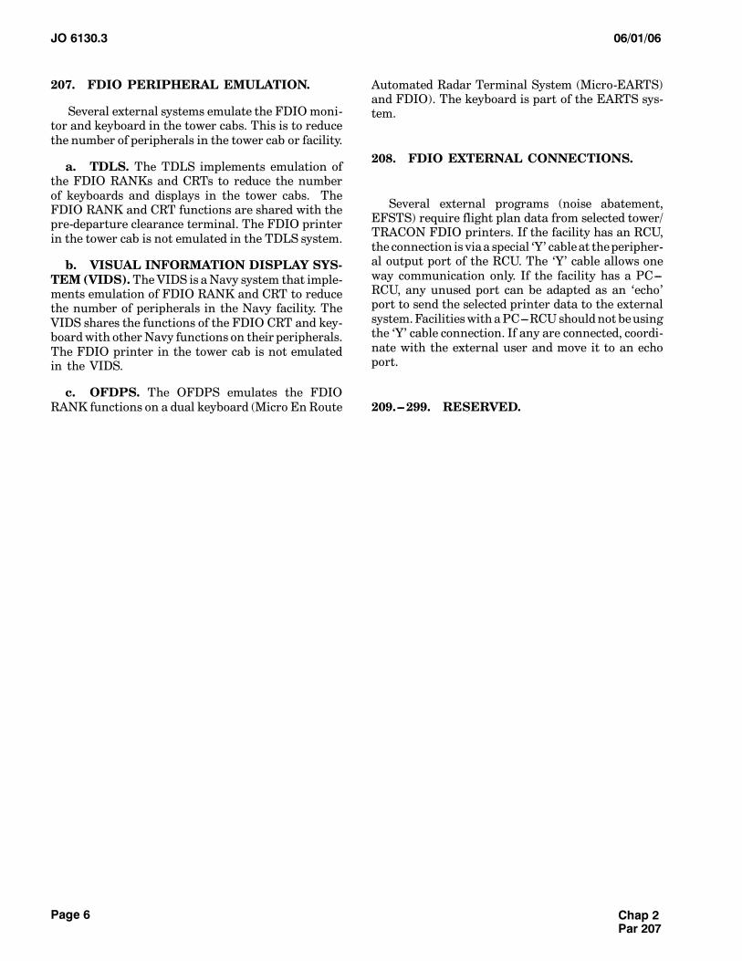
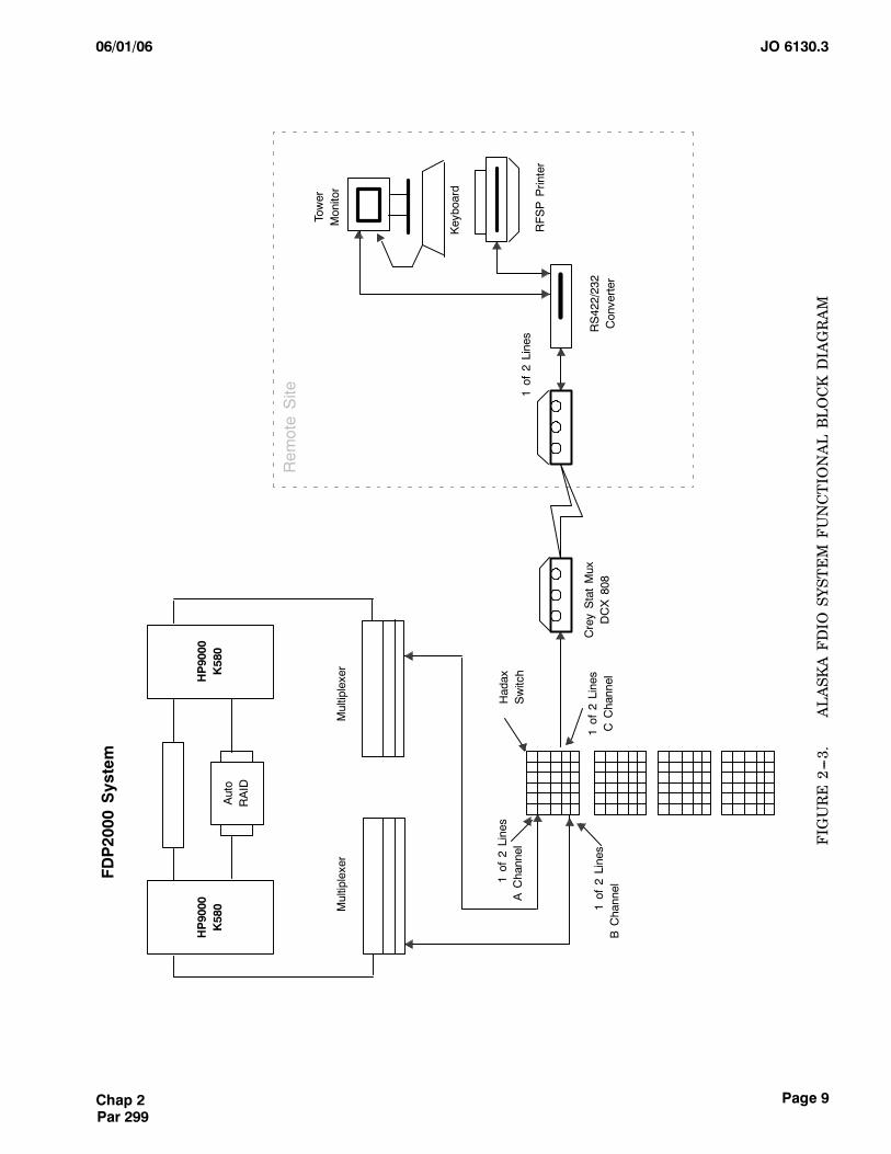
(1) In the En Route environment the FDIOCentral Control Unit (CCU) interfaceswith theFDIORemote Control Unit (RCU) or the Personal Comput-er-Remote Control Unit (PC---RCU) at the tower,Tower Radar Approach Control (TRACON), and theSan Juan CERAP facilities. In the Alaska center, noCCU is used. The center’s fight data processor com-municates directly with the associated tower periph-erals.
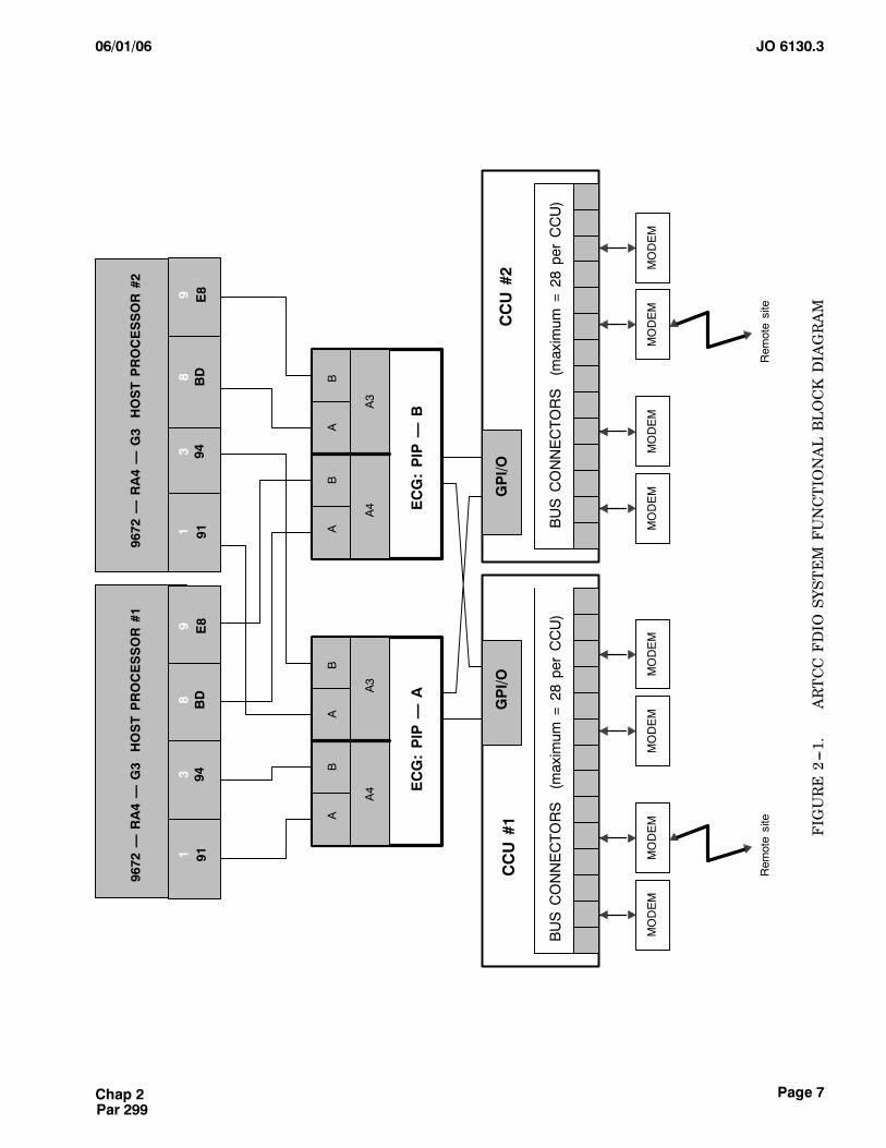
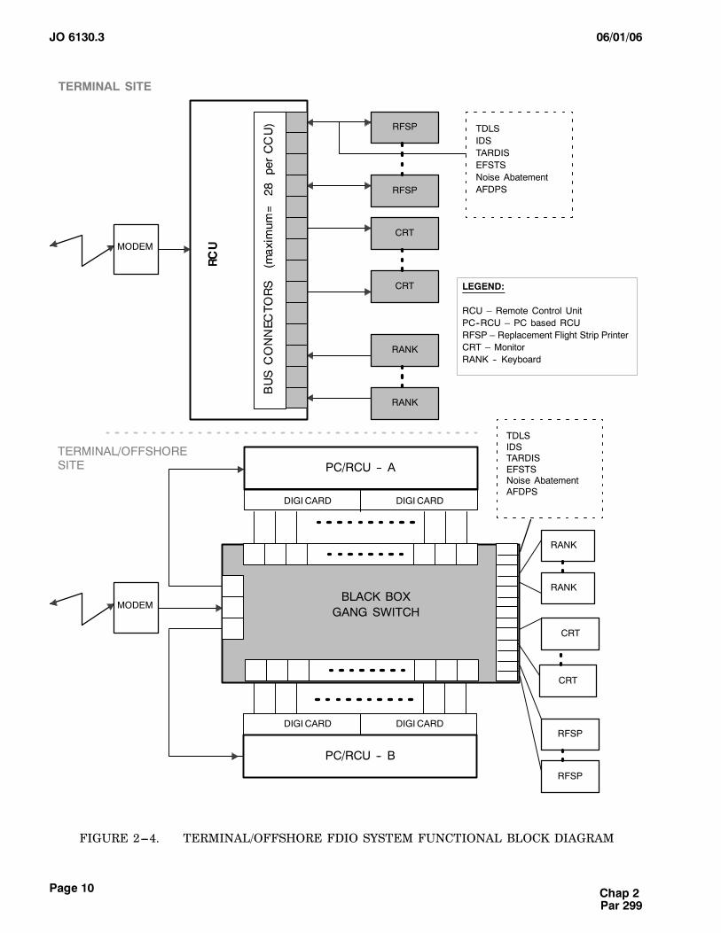
(2) In the Terminal environment (tower,TRACON, and military) facilities the FDIO RCU orPC---RCU interfaceswith the centersCCUor off shoreHonolulu Control Facility (HCF) series-1 equipment.It also drives local FDIO printers, monitors, key-boards, and external interfaces. In the Alaska envi-ronment, the tower’s PC---RCU communicates withthe center’s Flight Data Processor (FDP).
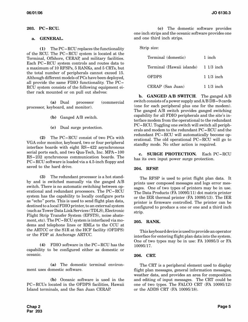
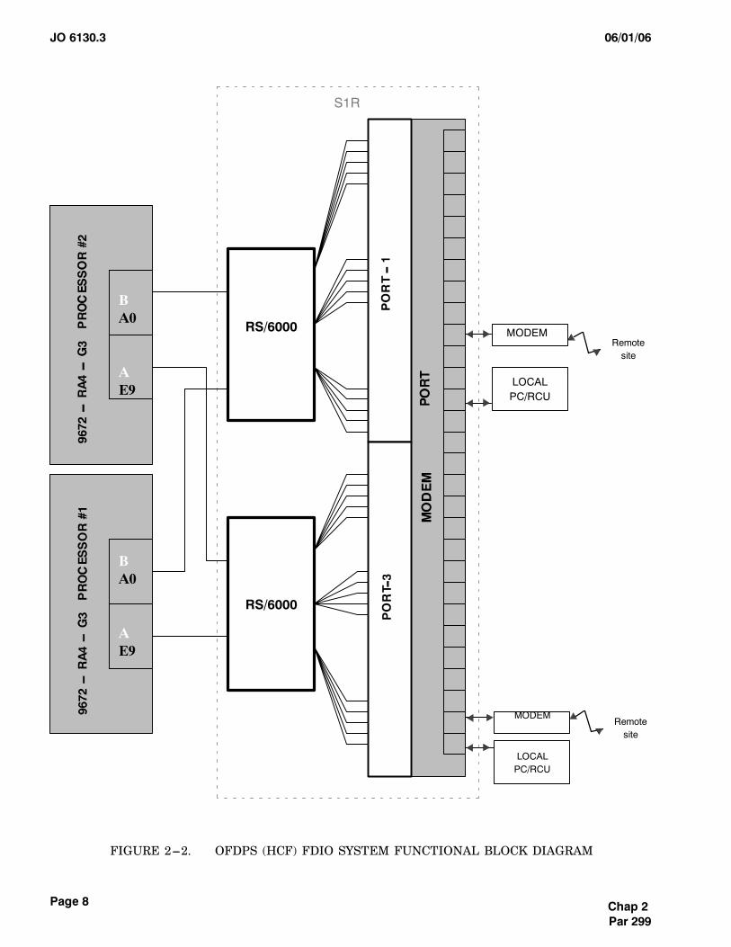
(3) In the Offshore environment (OffshoreFlightData Processing System (OFDPS)) theOFDPSSeries-1 Replacement (S1R) interfaces with the localPC---RCUs and terminal PC---RCUs. FDIO printersare used, but the keyboards for FDIO are a functionof the OFDPS system. The FDIO system supplies aninterface box between thePC---RCU and the local Vid-eo Graphic Array (VGA) monitors.
(4) In the San Juan CERAP environment,the local PC---RCUs are driven via the Miami centerFDIO CCU (local HOST patch in Miami allows CEN-RAP to accept strips as En Route and accepts control-ler messages to Miami as En Route). The PC---RCUsdrive local FDIO printers using En-Route formattedstrips, monitors, and keyboards.
b. The following FDIO equipment is used in thedifferent environments:
(1) En Route Centers:
CCU
Peripherals: none
(2) Terminal (FAA and military):
RCU
PC---RCU
Peripherals: keyboard, monitor, printer
(3) Offshore (HCF):
PC---RCU
Peripherals: printer
Interface box (between VGA monitorand PC---RCU)
(4) CERAP (San Juan):
PC---RCU
Peripherals: keyboard, monitor, printer
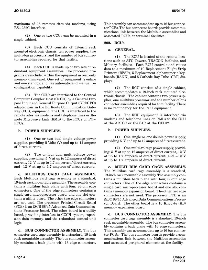
c. The FDIO system receives flight plan data,weather information, and general information fromthe central computer system at the ARTCC and theOFDPS located in Hawaii and the FDP located inAlaska. The FDIO system also distributes flight plandata to the center and offshore systems, where it issent on to the central computer for processing. Thecentral computer then sends the information to ATCusers as required. Refer to figures 2---1 through 2---4,(FDIO system functional block diagrams) for the cen-ter, terminal, oceanic, offshore, and CERAP overview.
201. CCU.
a. GENERAL.
(1) The CCUs are located at the ARTCC.Each CCU controls and routes data to and from a
Chap 2Par 200
JO 6130.3 06/01/06
Page 4
maximum of 28 remotes sites via modems, usingRS---232C interface.
(2) One or two CCUs can be mounted in asingle cabinet.
(3) Each CCU consists of 19-inch rackmounted electronic chassis: ten power supplies, twomulti-bus processors, and the number of bus connec-tor assemblies required for that facility.
(4) Each CCU is made up of two sets of re-dundant equipment assemblies. The processor pro-grams are includedwithin the equipment in read onlymemory (firmware). One set of equipment is onlineand one standby, and has automatic and manual re-configuration capability.
(5) The CCUs are interfaced to the CentralComputer Complex Host (CCCH) by a General Pur-pose Input and General Purpose Output (GPI/GPO)adapter pair in the En Route Communication Gate-way (ECG) equipment. The CCU is interfaced to theremote sites via modems and telephone lines or Re-mote Microwave Link (RML) to the RCUs or PC---RCUs.
b. POWER SUPPLIES.
(1) One or two dual single voltage powersupplies, providing 5 Volts (V) and up to 12 ampereof direct current.
(2) Two or four dual multi-voltage powersupplies, providing: 5 V at up to 12 amperes of directcurrent, 12 V at up to 1.7 amperes of direct current,and –12 V at up to 1.7 amperes of direct current.
c. MULTIBUS CARD CAGE ASSEMBLY.Each Multibus card cage assembly is a standard,19-inch rack mountable assembly. The assembly con-tains a multibus back plane with four, 86-pin edgeconnectors. One of the edge connectors contains asingle card microprocessor board, and one slot con-tains a utility board. The other two edge connectorsare not used. The processor Printed Circuit Board(PCB) is an iSCB 88/45 Advanced Data Communica-tions Processor board. The other board is a utilityboard, providing interface to CCCH system, expan-sion data memory, and the redundant control unitlogic.
d. BUS CONNECTOR ASSEMBLY. The busconnector card cage assembly is a standard, 19-inchrack mountable assembly. The bus connector assem-bly contains a back plane with 16 edge connectors.
This assembly can accommodate up to 16 bus connec-torPCBs.Thebusconnector boardsprovide a commu-nications link between the Multibus assemblies andassociated RCUs at terminal facilities.
202. RCUs.
a. GENERAL.
(1) The RCU is located at the remote loca-tions such as ATC Towers, TRACON facilities, andMilitary facilities. Each RCU controls and routesdata to a maximum of 10 Replacement Flight StripPrinters (RFSP), 5 Replacement alphanumeric key-boards (RANK), and 5 Cathode Ray Tube (CRT) dis-plays.
(2) The RCU consists of a single cabinet,which accommodates a 19-inch rack mounted elec-tronic chassis. The cabinet contains two power sup-plies, one multibus processor and the number of busconnector assemblies required for that facility. Thereis no redundancy for the RCU equipment.
(3) The RCU equipment is interfaced viamodems and telephone lines or RMLs to the CCUat the ARTCC or the S1R at the OFDPS.
b. POWER SUPPLIES.
(1) One single or one double power supply,providing 5 V and up to 12 amperes of direct current.
(2) One multi-voltage power supply, provid-ing: 5 V at up to 12 amperes of direct current, 12 Vat up to 1.7 amperes of direct current, and ---12 Vat up to 1.7 amperes of direct current.
c. MULTI BUS CARD CAGE ASSEMBLY.The Multibus card cage assembly is a standard,19-inch rack mountable assembly. The assembly con-tains a multibus back plane with four, 86-pin edgeconnectors. One of the edge connectors contains asingle card microprocessor board and one slot con-tains a memory expansion board. The other two edgeconnectors are not used. The processor PCB is aniSBC 88/45 Advanced Data Communications Proces-sor Board. The other board is a 16 Kilobyte (KB)memory expansion board.
d. BUS CONNECTOR ASSEMBLY. The busconnector card cage assembly is a standard, 19-inchrack mountable assembly. The bus connector assem-bly contains a back plane with 16 edge connectors.This assembly can accommodate up to 16 bus connec-tor PCBs. The bus connector boards provide a com-munications link between the Multibus assembliesand associated peripheral elements at the facility.
Chap 2Par 201
JO 6130.306/01/06
Page 5
203. PC---RCU.
a. GENERAL.
(1) ThePC---RCU replaces the functionalityof the RCU. The PC---RCU system is located at theTerminal, Offshore, CERAP, and military facilities.Each PC---RCU system controls and routes data toa maximum of 10 RFSPs, 5 RANKs, and 5 CRTs, butthe total number of peripherals cannot exceed 15.Although differentmodels of PCs have been deployed,all provide the same FDIO functionality. The PC---RCU system consists of the following equipment ei-ther rack mounted or on pull out shelves:
(a) Dual processor (commercialprocessor, keyboard, and monitor).
(b) Ganged A/B switch.
(c) Dual surge protection.
(2) The PC---RCU consist of two PCs withVGA color monitor, keyboard, two or four peripheralinterface boards with eight RS---422 asynchronousserial ports each, and two Qua-Tech, Inc. MPA---100RS---232 synchronous communication boards. ThePC---RCU software is loaded via a 4.5-inch floppy andsaved to the hard drive.
(3) The redundant processor is a hot stand-by and is switched manually via the ganged A/Bswitch. There is no automatic switching between op-erational and redundant processors. The PC---RCUsystem has the capability to locally configure portsas “echo” ports. This is used to send flight plan data,destined to a local FDIOprinter, to an external system(suchasTowerDataLinkServices (TDLS),ElectronicFlight Strip Transfer System (EFSTS), noise abate-ment, etc). ThePC---RCU system is interfaced viamo-dems and telephone lines or RMLs to the CCU atthe ARTCC or the S1R at the HCF facility (OFDPS)or the FDP at Anchorage ARTCC.
(4) FDIO software in the PC---RCU has thecapability to be configured either as domestic oroceanic.
(a) The domestic terminal environ-ment uses domestic software.
(b) Oceanic software is used in thePC---RCUs located in the OFDPS facilities, HawaiiIsland terminals, and the San Juan CERAP.
(c) The domestic software providesone inch strips and the oceanic software provides oneand one third inch strips.
Strip size:
Terminal (domestic) 1 inch
Terminal (Hawaii islands) 1 1/3 inch
OFDPS 1 1/3 inch
CERAP (San Juan) 1 1/3 inch
b. GANGED A/B SWITCH. The ganged A/Bswitch consists of a power supply andA/BDB---9 cards(one for each peripheral plus one for the modem).The ganged A/B switch provides ganged switchingcapability for all FDIO peripherals and the site’s in-terfacemodem from the operational to the redundantPC---RCU. Toggling one switch will switch all periph-erals and modem to the redundant PC---RCU and theredundant PC---RCU will automatically become op-erational. The old operational PC---RCU will go tostandby mode. No other action is required.
c. SURGE PROTECTION. Each PC---RCUhas its own input power surge protection.
204. RFSP.
The RFSP is used to print flight plan data. Itprints user composed messages and logs error mes-sages. One of two types of printers may be in use.The Data Products (FA 10095/11) dot matrix printeror the IER thermal printer (FA 10095/13). The IERprinter is firmware controlled. The printer can beconfigured to produce a one or one and a third inchstrip.
205. RANK.
Thiskeyboarddevice isused toprovide anoperatorinterface for entering flight plan data into the system.One of two types may be in use: FA 10095/3 or FA10095/17.
206. CRT.
The CRT is a peripheral element used to displayflight plan messages, general information messages,weather data, and provides an area for compositionand editing of input messages. The CRT could beone of two types. The FALCO CRT (FA 10095/12)or the ADDS CRT (FA 10095/18).
Chap 2Par 203
JO 6130.3 06/01/06
Page 6
207. FDIO PERIPHERAL EMULATION.
Several external systems emulate the FDIOmoni-tor and keyboard in the tower cabs. This is to reducethe number of peripherals in the tower cab or facility.
a. TDLS. The TDLS implements emulation ofthe FDIO RANKs and CRTs to reduce the numberof keyboards and displays in the tower cabs. TheFDIO RANK and CRT functions are shared with thepre-departure clearance terminal. The FDIO printerin the tower cab is not emulated in the TDLS system.
b. VISUAL INFORMATION DISPLAY SYS-TEM (VIDS).TheVIDS is aNavy system that imple-ments emulation of FDIO RANK and CRT to reducethe number of peripherals in the Navy facility. TheVIDS shares the functions of the FDIO CRT and key-boardwith other Navy functions on their peripherals.The FDIO printer in the tower cab is not emulatedin the VIDS.
c. OFDPS. The OFDPS emulates the FDIORANK functions on a dual keyboard (Micro En Route
Automated Radar Terminal System (Micro-EARTS)and FDIO). The keyboard is part of the EARTS sys-tem.
208. FDIO EXTERNAL CONNECTIONS.
Several external programs (noise abatement,EFSTS) require flight plan data from selected tower/TRACON FDIO printers. If the facility has an RCU,the connection is viaa special ‘Y’ cableat theperipher-al output port of the RCU. The ‘Y’ cable allows oneway communication only. If the facility has a PC---RCU, any unused port can be adapted as an ‘echo’port to send the selected printer data to the externalsystem.Facilitieswith aPC---RCUshouldnot beusingthe ‘Y’ cable connection. If any are connected, coordi-nate with the external user and move it to an echoport.
209.---299. RESERVED.
Chap 2Par 207
JO 6130.306/01/06
Page 7Chap 2Par 299
9672
—RA4—
G3
HOSTPROCESSOR#1
9 E8
ECG:PIP
—A
A4
BUSCONNECTORS
(maximum
=28
perCCU)
GPI/O
CCU#1
BUSCONNECTORS
(maximum
=28
perCCU)
CCU#2
GPI/O
ECG:PIP
—B
A3
A4
A3
AB
AB
AB
AB
9672
—RA4—
G3
HOSTPROCESSOR#2
3 948 BD
1 919 E8
3 948 BD
1 91
MODEM
Rem
otesite
MODEM
MODEM
MODEM
MODEM
MODEM
MODEM
MODEM
Rem
otesite
FIGURE2---1.
ARTCCFDIO
SYSTEMFUNCTIONALBLOCKDIAGRAM
JO 6130.3 06/01/06
Page 8 Chap 2Par 299
S1R
Remotesite
BA0
AE9
BA0
AE9
RS/6000
LOCALPC/RCU
LOCALPC/RCU
MODEM
MODEM
RS/6000
Remotesite
FIGURE 2---2. OFDPS (HCF) FDIO SYSTEM FUNCTIONAL BLOCK DIAGRAM
JO 6130.306/01/06
Page 9Chap 2Par 299
FDP2000
System
HP9000
K580
HP9000
K580
Auto
RAID
Rem
oteSite
Tower
Monitor
Multiplexer
Multiplexer
Keyboard
1of
2Lines
AChannel
1of
2Lines
BChannel
CreyStatMux
DCX808
1of
2Lines
CChannel
Hadax
Switch
RS422/232
Converter
1of
2Lines
RFSPPrinter
FIGURE2---3.
ALASKAFDIO
SYSTEMFUNCTIONALBLOCKDIAGRAM
JO 6130.3 06/01/06
Page 10 Chap 2Par 299
TERMINAL SITE
RFSP
RFSP
CRT
CRT
RANK
RANK
TDLSIDSTARDISEFSTSNoise AbatementAFDPS
MODEM
LEGEND:
RCU – Remote Control UnitPC--RCU – PC based RCURFSP – Replacement Flight Strip PrinterCRT – MonitorRANK -- Keyboard
TERMINAL/OFFSHORESITE
MODEM
PC/RCU -- B
DIGICARD
BLACK BOXGANG SWITCH
DIGICARD
PC/RCU -- A
DIGICARD DIGICARD
TDLSIDSTARDISEFSTSNoise AbatementAFDPS
RANK
RANK
RFSP
RFSP
CRT
CRT
FIGURE 2---4. TERMINAL/OFFSHORE FDIO SYSTEM FUNCTIONAL BLOCK DIAGRAM
JO 6130.306/01/06
Page 11
CHAPTER 3. STANDARDS AND TOLERANCES
300. GENERAL.
a. This chapter prescribes the standards and tol-erances for FDIO equipment, as definedanddescribedin Order 6000.15. All key performance parametersand/or key inspection elements are clearly identifiedby an arrow placed to the left of the applicable item.
b. Definitions of standard, initial tolerance, andoperating tolerances for the purpose of this handbookare as follows:
(1) Standard.Theoptimumvalue assignedto an essential parameter of the equipment.
(2) Initial Tolerance.Themaximumdevi-ation, fromthe standardvalue of theparameter,whichis permissible at the time of initial tune-up or amajorreadjustment.
(3) Operating Tolerance. The maximumdeviation, from the standard value of the parameter,beyond which remedial action by maintenance per-sonnel is mandatory.
Chap 3Par 300
JO 6130.3 06/01/06
Page 12
STANDARDS AND TOLERANCES
ParameterReference
StandardTolerance/Limit
ParameterReferenceParagraph Standard
Initial Operating
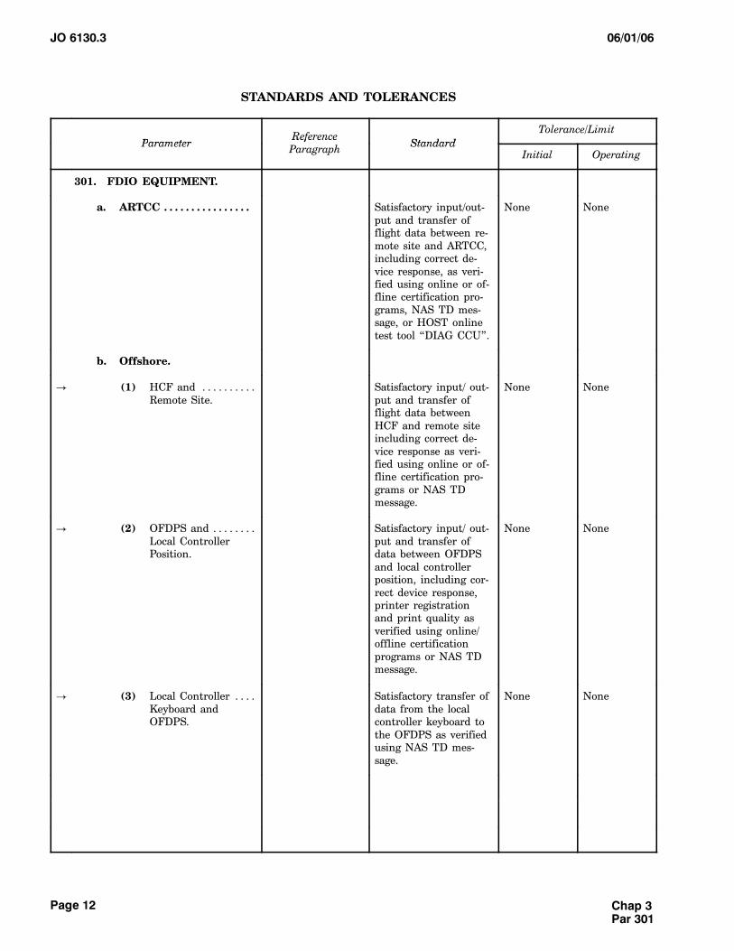
301. FDIO EQUIPMENT.
a. ARTCC . . . . . . . . . . . . . . . . Satisfactory input/out-put and transfer offlight data between re-mote site and ARTCC,including correct de-vice response, as veri-fied using online or of-fline certification pro-grams, NAS TD mes-sage, or HOST onlinetest tool “DIAG CCU”.
None None
b. Offshore.
! (1) HCF and . . . . . . . . . .Remote Site.
Satisfactory input/ out-put and transfer offlight data betweenHCF and remote siteincluding correct de-vice response as veri-fied using online or of-fline certification pro-grams or NAS TDmessage.
None None
! (2) OFDPS and . . . . . . . .Local ControllerPosition.
Satisfactory input/ out-put and transfer ofdata between OFDPSand local controllerposition, including cor-rect device response,printer registrationand print quality asverified using online/offline certificationprograms or NAS TDmessage.
None None
! (3) Local Controller . . . .Keyboard andOFDPS.
Satisfactory transfer ofdata from the localcontroller keyboard tothe OFDPS as verifiedusing NAS TD mes-sage.
None None
Chap 3Par 301
JO 6130.306/01/06
Page 13
STANDARDS AND TOLERANCES (Continued)
Tolerance/LimitStandard
ReferenceParagraphParameter
OperatingInitialStandard
ReferenceParagraphParameter
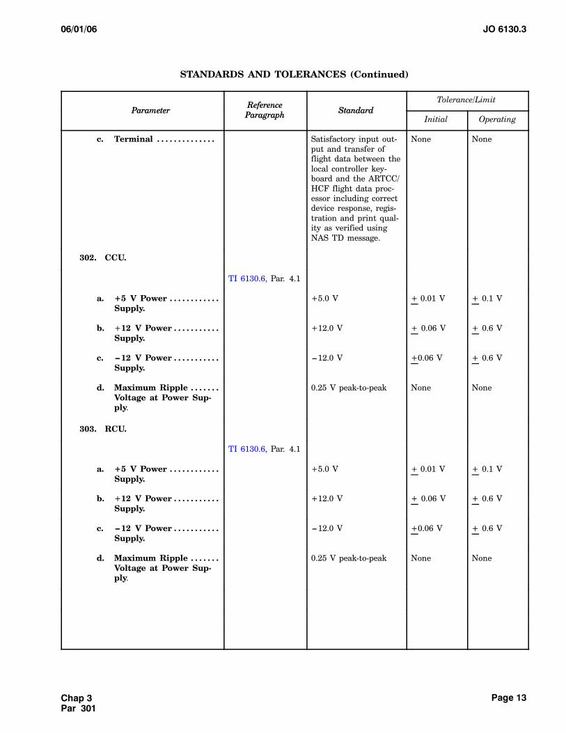
c. Terminal . . . . . . . . . . . . . . Satisfactory input out-put and transfer offlight data between thelocal controller key-board and the ARTCC/HCF flight data proc-essor including correctdevice response, regis-tration and print qual-ity as verified usingNAS TD message.
None None
302. CCU.
TI 6130.6, Par. 4.1
a. +5 V Power . . . . . . . . . . . .Supply.
+5.0 V + 0.01 V + 0.1 V
b. +12 V Power . . . . . . . . . . .Supply.
+12.0 V + 0.06 V + 0.6 V
c. ---12 V Power . . . . . . . . . . .Supply.
---12.0 V +0.06 V + 0.6 V
d. Maximum Ripple . . . . . . .Voltage at Power Sup-ply.
0.25 V peak-to-peak None None
303. RCU.
TI 6130.6, Par. 4.1
a. +5 V Power . . . . . . . . . . . .Supply.
+5.0 V + 0.01 V + 0.1 V
b. +12 V Power . . . . . . . . . . .Supply.
+12.0 V + 0.06 V + 0.6 V
c. ---12 V Power . . . . . . . . . . .Supply.
---12.0 V +0.06 V + 0.6 V
d. Maximum Ripple . . . . . . .Voltage at Power Sup-ply.
0.25 V peak-to-peak None None
Chap 3Par 301
JO 6130.3 06/01/06
Page 14
STANDARDS AND TOLERANCES (Continued)
Tolerance/LimitStandard
ReferenceParagraphParameter
OperatingInitialStandard
ReferenceParagraphParameter
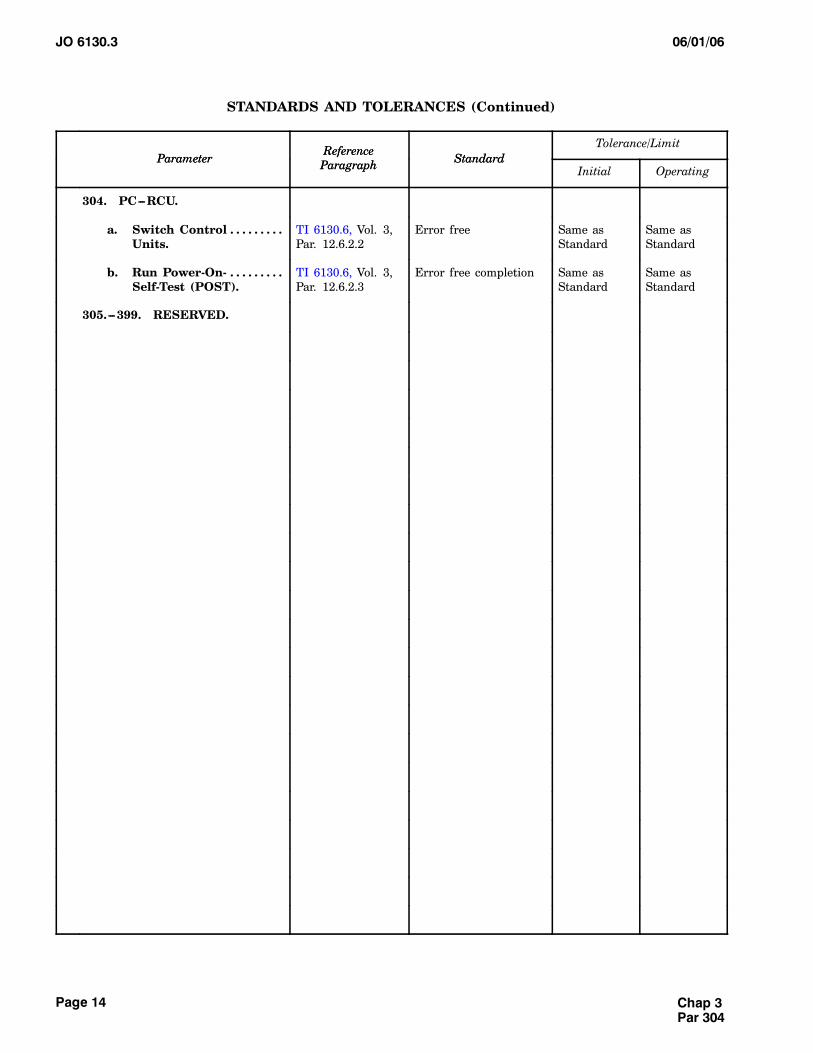
304. PC---RCU.
a. Switch Control . . . . . . . . .Units.
TI 6130.6, Vol. 3,Par. 12.6.2.2
Error free Same asStandard
Same asStandard
b. Run Power-On- . . . . . . . . .Self-Test (POST).
TI 6130.6, Vol. 3,Par. 12.6.2.3
Error free completion Same asStandard
Same asStandard
305.---399. RESERVED.
Chap 3Par 304
JO 6130.306/01/06
Page 15
CHAPTER 4. PERIODIC MAINTENANCE
400. GENERAL.
a. This chapter establishes all the maintenanceactivities required for the FDIO equipment on a peri-odic, recurring basis, and the schedules for their ac-complishment. The chapter is divided into twosections. The first section identifies the performancechecks (i.e., tests, measurements, and observations)of normal operation controls and functions, whicharenecessary to determinewhether operation iswith-in established tolerances/limits. The second sectionidentifies other tasks that are necessary to preventdeterioration and ensure reliable operation. Refer toOrder 6000.15 for additional general guidance.
b. All reference paragraphs pertaining to stan-
dards and tolerance/limits are found in chapter 3 ofthis order, unless otherwise stated.
c. The performance checks and maintenancetasks are not to be taken as the minimum work re-quired for proper maintenance, rather as the maxi-mum interval permitted between task. This chapterwill reference specific paragraphs for the mainte-nance activities listed in the individual equipmentinstruction books and their frequency of accomplish-ment.
d. Additional maintenance activities, not listedin the instruction books, will refer the user to chapter5 of this handbook for the appropriate maintenanceprocedures.
Chap 4Par 400
JO 6130.3 06/01/06
Page 16
Section 1. PERFORMANCE CHECKS
Reference Paragraph
Performance Checks Standards &Tolerances
MaintenanceProcedures
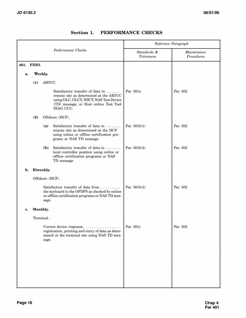
401. FDIO.
a. Weekly.
(1) ARTCC.
Satisfactory transfer of data to . . . . . . . .remote site as determined at the ARTCCusingOLC,OLCT, NSCT,NAS TestDevice(TD) message, or Host online Test ToolDIAG CCU.
Par. 301a Par. 502
(2) Offshore (HCF).
(a) Satisfactory transfer of data to . . . . . . . .remote site as determined at the HCFusing online or offline certification pro-grams or NAS TD message.
Par. 301b(1) Par. 502
(b) Satisfactory transfer of data to . . . . . . . .local controller position using online oroffline certification programs or NASTD message.
Par. 301b(2) Par. 502
b. Biweekly.
Offshore (HCF).
Satisfactory transfer of data from . . . . . . . . . . .the keyboard to the OFDPS as checked by onlineor offline certification programs or NAS TDmes-sage.
Par. 301b(3) Par. 502
c. Monthly.
Terminal.
Correct device response, . . . . . . . . . . . . . . . . . . .registration, printing and entry of data as deter-mined at the terminal site using NAS TD mes-sage.
Par. 301c Par. 502
Chap 4Par 401
JO 6130.306/01/06
Page 17
Section 1. PERFORMANCE CHECKS (Continued)
Performance Checks
Reference Paragraph
Performance Checks MaintenanceProcedures
Standards &Tolerances
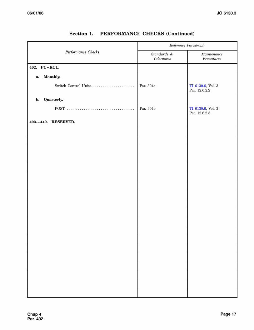
402. PC---RCU.
a. Monthly.
Switch Control Units. . . . . . . . . . . . . . . . . . . . . . . Par. 304a TI 6130.6, Vol. 3Par. 12.6.2.2
b. Quarterly.
POST. . . . . . . . . . . . . . . . . . . . . . . . . . . . . . . . . . . . . Par. 304b TI 6130.6, Vol. 3Par. 12.6.2.3
403.---449. RESERVED.
Chap 4Par 402
JO 6130.3 06/01/06
Page 18
Section 2. OTHER MAINTENANCE CHECKS
Reference Paragraph
MaintenanceChecks Standards &Tolerances
MaintenanceProcedures
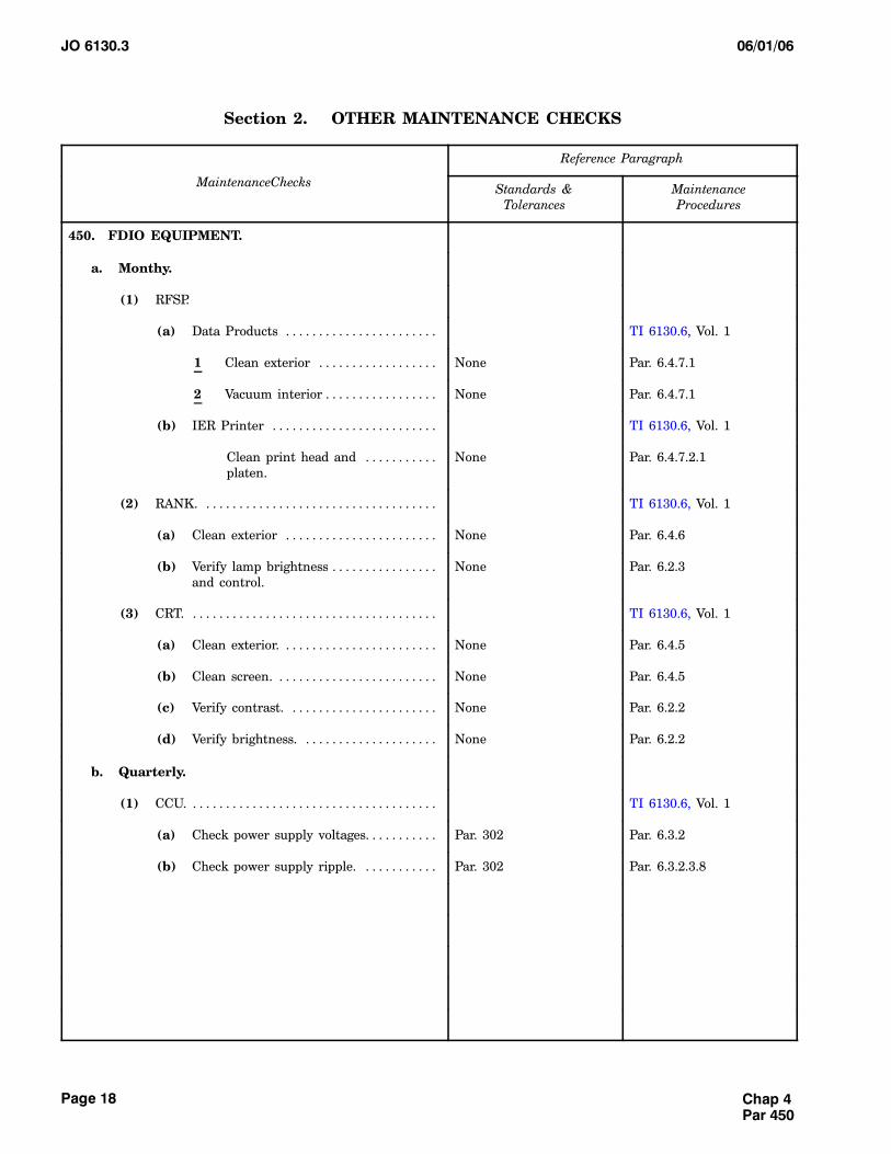
450. FDIO EQUIPMENT.
a. Monthy.
(1) RFSP.
(a) Data Products . . . . . . . . . . . . . . . . . . . . . . . TI 6130.6, Vol. 1
1 Clean exterior . . . . . . . . . . . . . . . . . . None Par. 6.4.7.1
2 Vacuum interior . . . . . . . . . . . . . . . . . None Par. 6.4.7.1
(b) IER Printer . . . . . . . . . . . . . . . . . . . . . . . . . TI 6130.6, Vol. 1
Clean print head and . . . . . . . . . . .platen.
None Par. 6.4.7.2.1
(2) RANK. . . . . . . . . . . . . . . . . . . . . . . . . . . . . . . . . . . . TI 6130.6, Vol. 1
(a) Clean exterior . . . . . . . . . . . . . . . . . . . . . . . None Par. 6.4.6
(b) Verify lamp brightness . . . . . . . . . . . . . . . .and control.
None Par. 6.2.3
(3) CRT. . . . . . . . . . . . . . . . . . . . . . . . . . . . . . . . . . . . . . TI 6130.6, Vol. 1
(a) Clean exterior. . . . . . . . . . . . . . . . . . . . . . . . None Par. 6.4.5
(b) Clean screen. . . . . . . . . . . . . . . . . . . . . . . . . None Par. 6.4.5
(c) Verify contrast. . . . . . . . . . . . . . . . . . . . . . . None Par. 6.2.2
(d) Verify brightness. . . . . . . . . . . . . . . . . . . . . None Par. 6.2.2
b. Quarterly.
(1) CCU. . . . . . . . . . . . . . . . . . . . . . . . . . . . . . . . . . . . . . TI 6130.6, Vol. 1
(a) Check power supply voltages. . . . . . . . . . . Par. 302 Par. 6.3.2
(b) Check power supply ripple. . . . . . . . . . . . Par. 302 Par. 6.3.2.3.8
Chap 4Par 450
JO 6130.306/01/06
Page 19
Section 2. OTHER MAINTENANCE CHECKS (Continued)
MaintenanceChecks
Reference Paragraph
MaintenanceChecks MaintenanceProcedures
Standards &Tolerances
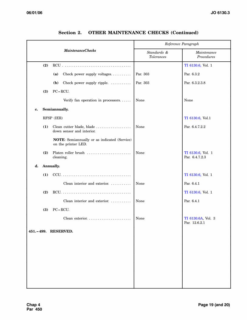
(2) RCU . . . . . . . . . . . . . . . . . . . . . . . . . . . . . . . . . . . . . TI 6130.6, Vol. 1
(a) Check power supply voltages. . . . . . . . . . . Par. 303 Par. 6.3.2
(b) Check power supply ripple. . . . . . . . . . . . Par. 303 Par. 6.3.2.3.8
(3) PC---RCU.
Verify fan operation in processors. . . . . . None None
c. Semiannually.
RFSP (IER) TI 6130.6, Vol.1
(1) Clean cutter blade, blade . . . . . . . . . . . . . . . . . . .down sensor and interior.
None Par. 6.4.7.2.2
NOTE: Semiannually or as indicated (Service)on the printer LED.
(2) Platen roller brush . . . . . . . . . . . . . . . . . . . . . . . .cleaning.
None TI 6130.6, Vol. 1Par. 6.4.7.2.3
d. Annually.
(1) CCU. . . . . . . . . . . . . . . . . . . . . . . . . . . . . . . . . . . . . . TI 6130.6, Vol. 1
Clean interior and exterior. . . . . . . . . . . . None Par. 6.4.1
(2) RCU. . . . . . . . . . . . . . . . . . . . . . . . . . . . . . . . . . . . . . TI 6130.6, Vol. 1
Clean interior and exterior. . . . . . . . . . . . None Par. 6.4.1
(3) PC---RCU.
Clean exterior. . . . . . . . . . . . . . . . . . . . . . . . None TI 6130.6A, Vol. 3Par. 12.6.2.1
451.---499. RESERVED.
Page 19 (and 20)Chap 4Par 450
JO 6130.306/01/06
Page 21
CHAPTER 5. MAINTENANCE PROCEDURES
500. GENERAL.
This chapter establishes theprocedures for accom-plishing the various essential maintenance activitieswhich are required for the FDIO equipment, on eithera periodic or incidental basis. The chapter is dividedinto three sections. The first section describes the
procedures to be used in making the performancechecks listed in chapter 4, section 1. The second sec-tion describes theprocedures for doing the tasks listedin chapter 4, section 2. The third section describesprocedures for doing special tasks, usually nonsched-uled and not listed in chapter 4. Refer to Order6000.15 for additional general guidance.
Chap 5Par 500
JO 6130.3 06/01/06
Page 22
Section 1. PERFORMANCE CHECK PROCEDURES
501. GENERAL PERFORMANCE CHECKPROCEDURES.
All performance checking procedures, and otherguidance essential to maintaining continuous errorfree operation of the FDIO equipment is found inTI 6130.6.
502. TD PROCEDURE.
a. Enter the appropriate TD command for theposition being tested.
(1) Following is the format for the TD mes-sage at a domestic facility.
TD aaaL or TD aaaLbbb
(a) Where aaa is the identifier for thetower or approach control facility.
(b) Where L is replaced withT for tow-er printer, with D for approach control departureprinter, with A for approach control arrival printer,and with O for approach control over flight printer.
(c) Where bbb is required only if aprinter name is adapted for an approach control de-parture or arrival printer.
(Refer toNAS---MD---311, paragraph8.5for complete format).
(2) Following is the format for the TD mes-sage at an offshore facility:
TD P or TD
(a) Where P will cause the Test Devicemessage to print on the printer associated with thekeyboard.
(b) If TD is not followed by the P, theTest Device message will be displayed on the CRTassociated with the keyboard.
(Refer to NAS---MD---5311, paragraph 6.2 forcomplete format.)
(3) Following is the format for the TD mes-sage at a facility in Alaska:
TD sss
(a) Where sss is the sector number ofthe printer where the message will be printed.
(b) If the sector number is omitted,andthe entering source is not a supervisory position, theTD message will be printed on the printer associatedwith the keyboard from which the TD was entered.
(c) If theTDis enteredat a supervisorystation and the sector number is omitted, theTDmes-sage will be printed on all printers.
b. Ascertain correct device response, registra-tion, printing, and entry of data, taking correctivemaintenance actions as necessary.
c. Restore position and coordinate return withair traffic users.
503.---539. RESERVED.
Chap 5Par 501
JO 6130.306/01/06
Page 23
Section 2. OTHER MAINTENANCE TASKS
540. GENERAL MAINTENANCE TASKS.
All other maintenance task procedures for theFDIO equipment is found inTI 6130.6.Housekeepingtasks such as equipment cleaning and the changing
of filters, lubrication of motors, and the like, are cov-ered in Order 6000.15.
541.---569. RESERVED.
Section 3. SPECIAL MAINTENANCE PROCEDURES
570.---599. RESERVED.
Chap 5Par 540
Chap 5Par 570
Page 23 (and 24)
JO 6130.306/01/06Appendix 1
Page 1
APPENDIX 1. CERTIFICATION REQUIREMENTS
Refer to Order 6000.15, Appendix 3, for the listof constituent NAS, and for general guidance on thecertification of services and systems.
NOTE: No certification is required for the FDIO
hardware system. Service certification, if required,is the responsibility of the ARTCCs and Offshore(HCF) facilities. Personnel at these facilities shouldrefer to the latest version of Orders 6100.1 and6110.8 for requirements.
Page 1 (and 2)
JO 6130.306/01/06Appendix 2
Page 1
APPENDIX 2. GLOSSARY OF TERMS AND ABBREVIATIONS
Alphanumeric A combination of alphabetic andnumeric characters.
Central The physical components of the 3083Computer IBM computer and its associated
peripheral equipment.
Equipment, The auxiliary machines which mayPeripheral be placed under the control of a
control unit. Examples of this arekeyboards, monitors, printers.
Interface The common boundary of two bodiesor spaces. The functionalintersystem relationship whichinfluence system accomplishments.
Keyboard A computer entry device used toentermessages into the computer forprocessing.
Message A group of words transported as aunit.
Modem Modulating and demodulating(communication equipment).
National The common system of facilities,Airspace equipment regulations, procedures,System and personnel required for the safe
and efficient movement of civil and
military aircraft in airspace withinthe jurisdiction of the United States.
Offline In computer language, pertaining toauxiliary equipment or output devicenot under control of the centralprocessing unit.
Online In computer language, pertaining tooperation of devices under directcontrol of the computer.
Operational Equipment that is in actual use forEquipment air traffic control.
Output The equipment used to transferEquipment information out of a computer.
Software In computer terminology, all theprogramming systems required foreffective data processing operations.
Subsystem An essential, functional part of asystem which supports a dataprocessing operation.
System The engineering model computerSupport installation and overhead facility
located at the FAA Technical Center.
Page 1 (and 2)
JO 6130.306/01/06Appendix 3
Page 1
APPENDIX 3. ABBREVIATIONS
ARTCC Air Route Traffic Control Center
ARTS Approach Radar Terminal System
AT Air Traffic
ATC Air Traffic Control
CCCH Central Computer Complex Host
CCD Configuration Control Decision
CCU Central Control Unit
CERAP Center Radar ARTS Presentation
CM Configuration Management
CRT Cathode Ray Tube
EARTS EnhancedApproachRadarTerminalSystem
ECG En Route Communication Gateway
EFSTS Electronic Flight Strip TransferSystem
FAA Federal Aviation Administration
FDIO Flight Data Input/Output
FDP Flight Data Processor
GPI General Purpose Input
GPO General Purpose Output
HCF Honolulu Control Facility
ID Identification
IER Name of Printer Manufacture
KB Kilobyte
KYBD Keyboard
LED Light Emitting Diode
MEARTS Micro En Route Automated RadarTerminal System
NAPRS National Airspace PerformanceReporting System
NAS National Airspace System
NCP NAS Changer Proposal
NOM NAS Operations Manager
NSCT NAS Certification Tape
OFDPS Offshore Flight Data ProcessingSystem
OLC Online Certification
Par. Paragraph
PC Personal Computer
PCB Printed Circuit Board
PC---RCU Personal Computer-Remote ControlUnit
PIP Primary Interface Processor
POST Power-On-Reset Test
RANK Replacement Alphanumerickeyboard
RCU Remote Control Unit
RFSP Replacement Flight Strip Printer
RML Remote Microwave Link
S1R Series/1 Replacement
TRACON Tower Radar Approach Control
TD Test Device
TDLS Tower Data Link Services
TOS Technical Operations Services
V Volts
06/01/06JO 6130.3Appendix 3
Page 2
VGA Video Graphic Array
VIDS Visual Information Display System
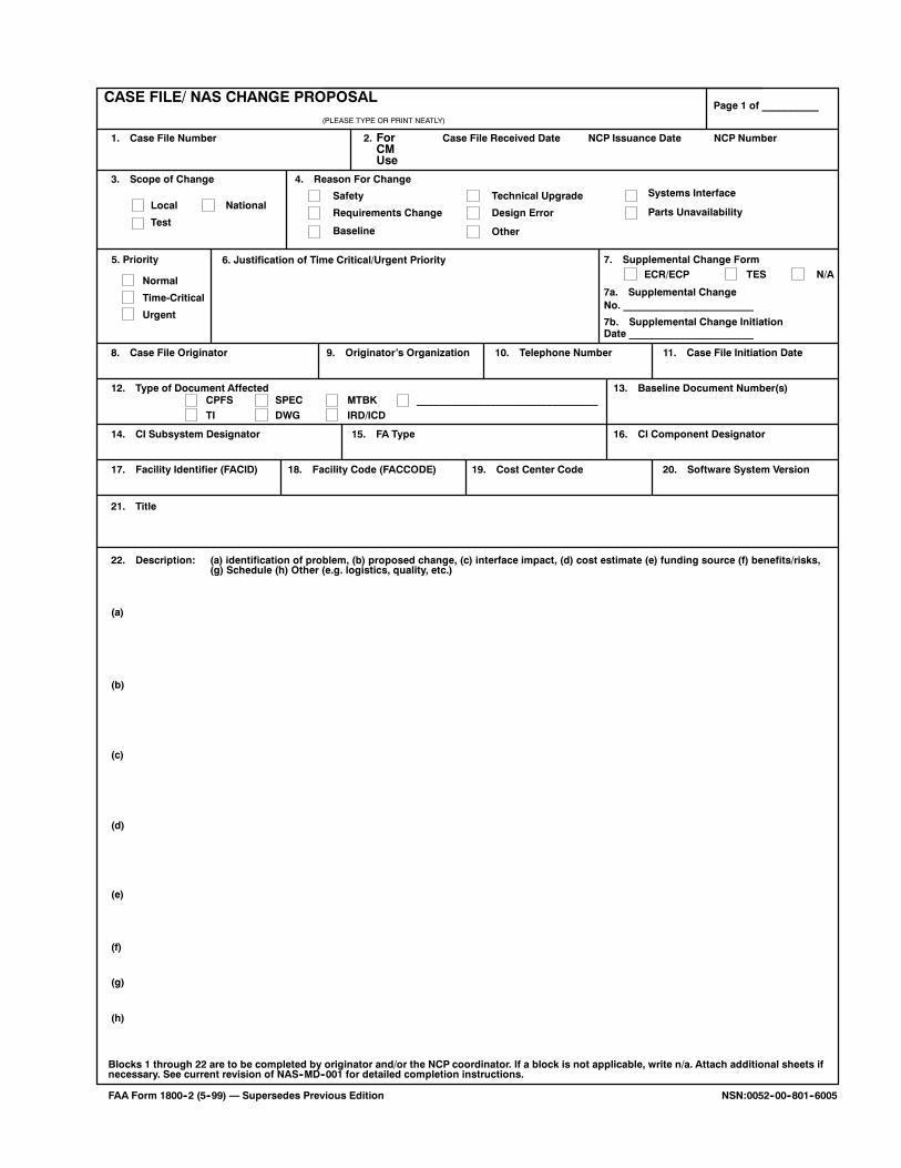
CASE FILE/ NAS CHANGE PROPOSAL
ForCMUse
Case File Received Date NCP Issuance Date NCP Number
Page 1 of __________
1. Case File Number 2.
3. Scope of Change 4. Reason For Change
5. Priority 7. Supplemental Change Form
7a. Supplemental Change
7b. Supplemental Change Initiation
8. Case File Originator 9. Originator’s Organization 10. Telephone Number 11. Case File Initiation Date
12. Type of Document Affected 13. Baseline Document Number(s)
14. CI Subsystem Designator 15. FA Type 16. CI Component Designator
17. Facility Identifier (FACID) 18. Facility Code (FACCODE) 19. Cost Center Code 20. Software System Version
21. Title
22. Description: (a) identification of problem, (b) proposed change, (c) interface impact, (d) cost estimate (e) funding source (f) benefits/risks,(g) Schedule (h) Other (e.g. logistics, quality, etc.)
(PLEASE TYPE OR PRINT NEATLY)
Local
Test
NationalSafety
Requirements Change
Technical Upgrade
Design Error
Normal
Time-Critical
Urgent
ECR/ECP TES N/A
CPFSTI
SPECDWG
MTBKIRD/ICD
Blocks 1 through 22 are to be completed by originator and/or the NCP coordinator. If a block is not applicable, write n/a. Attach additional sheets ifnecessary. See current revision of NAS--MD--001 for detailed completion instructions.
FAA Form 1800--2 (5--99) — Supersedes Previous Edition
Baseline Other
Parts Unavailability
Systems Interface
6. Justification of Time Critical/Urgent Priority
No. _______________________
Date ______________________
(a)
(b)
(c)
(d)
(e)
(f)
(g)
(h)
NSN:0052--00--801--6005
________________________________
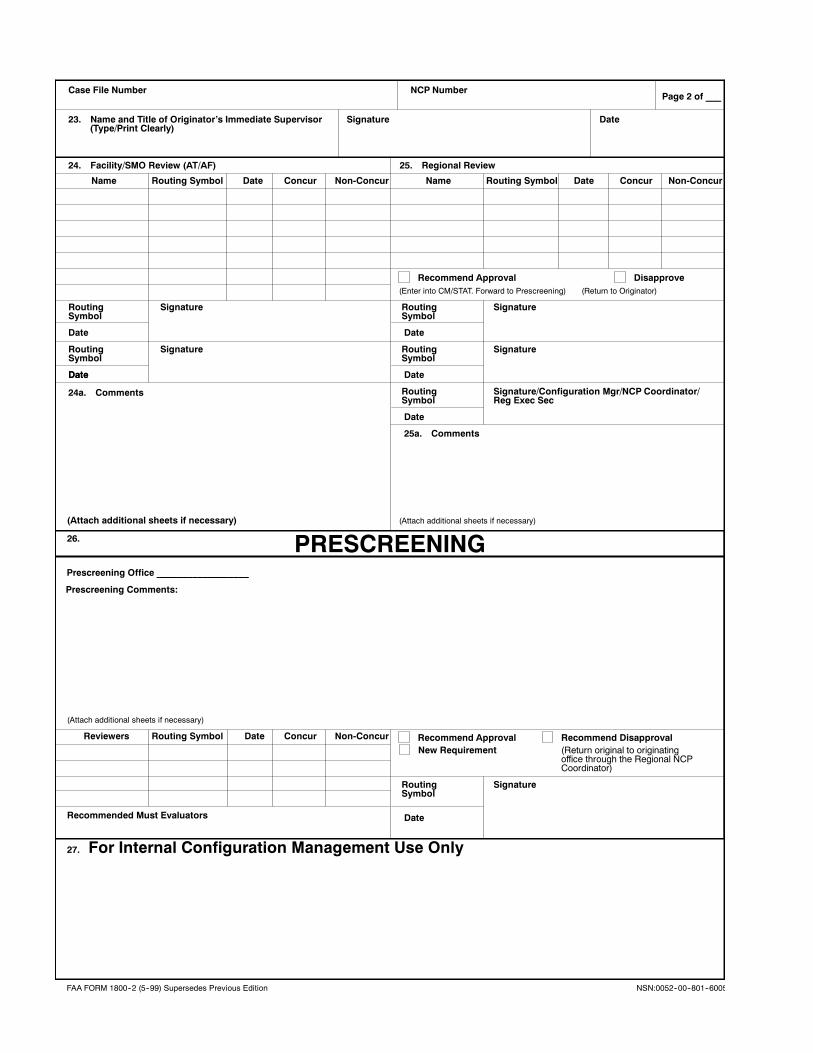
Case File Number NCP NumberPage 2 of ___
23. Name and Title of Originator’s Immediate Supervisor
24. Facility/SMO Review (AT/AF) 25. Regional Review
Name
Routing Signature
Date
Recommend Approval
Signature Date
Routing Symbol Date Concur Non-Concur Name Routing Symbol Date Concur Non-Concur
SymbolRouting SignatureSymbol
(Type/Print Clearly)
Date
Routing Signature
Date
SymbolRouting SignatureSymbol
DateDate
24a. Comments Routing Signature/Configuration Mgr/NCP Coordinator/Symbol
Date
Reg Exec Sec
25a. Comments
26.
(Attach additional sheets if necessary)
Reviewers Routing Symbol Date Concur Non-Concur Recommend Disapproval(Return original to originatingoffice through the Regional NCPCoordinator)
Routing SignatureSymbol
DateRecommended Must Evaluators
(Attach additional sheets if necessary) (Attach additional sheets if necessary)
27.
Recommend Approval Disapprove(Return to Originator)(Enter into CM/STAT. Forward to Prescreening)
PRESCREENINGPrescreening Office __________________
Prescreening Comments:
New Requirement
For Internal Configuration Management Use Only
FAA FORM 1800--2 (5--99) Supersedes Previous Edition NSN:0052--00--801--6005