Embed Size (px)
Citation preview

SUBCOURSE EDITIONTR0675 6
MAINTENANCE OFDIESEL-ELECTRIC LOCOMOTIVES
AND ROLLING STOCK
Fort Eustis, Virginia June 1976
Supersedes Trans 675, Maintenance of DieselElectric Locomotives andRolling Stock, Version 1, February 1969.

TRANS SUBCOURSE 675
MAINTENANCE OF DIESELELECTRIC LOCOMOTIVESAND ROLLING STOCK
INTRODUCTION
Maintenance of railway equipment is performed to keep equipment in asafe and serviceable condition. The effectiveness of that maintenancedirectly affects the efficiency of railway operations, particularly in atheater of operations. Military railway men and all transportation officersshould know how, when, and why to inspect and maintain railway equipment.
This subcourse introduces you to the Army's dieselelectriclocomotives and rolling stock, regulations that govern railway equipment andmaintenance, forms used to guide inspectors and maintenance men inperforming their duties, and preventive maintenance indicators for railwayequipment.
This is a twolesson subcourse, including two lesson exercises, lessonsolutions, and an examination. Before beginning this subcourse, ensure thatyour social security number (SSN) or student number and the subcourse numberare printed correctly on the response sheet. If either is incorrect, returnthe sheet to AIPD, calling attention to the error. AIPD will in turn sendyou a corrected sheet. You must also include your SSN or student number onall correspondence.
This subcourse consists of two lessons and an examination:
Credit Hours
Lesson 1 Army Rail Equipment; The 1DieselElectric Locomotive
2 Rolling Stock 1
Examination 1Total 3
You must complete the lesson exercises under the concept of selfpacedinstruction. You must grade the exercises yourself, using the lessonsolutions. Because of this, we have only forwarded one examination responsesheet with this subcourse. You must use this sheet to submit your answersto the examination questions. After successfully completing theexamination, you are entitled to three credit hours for the entiresubcourse.
To complete this subcourse, you must
o Study the text material assigned for each lesson.
1

o Answer each question in all the lesson exercises by marking orcircling your answer in the lesson book.
o Check your answers against the solutions provided in thesubcourse. Look up the text reference given on the solutionsheet if you answered any question incorrectly. Study thereference and evaluate all possible exercise solutions; makesure you understand why the correct answer is the best choice.
o After completing the lesson exercises to your satisfaction,complete the examination as directed and mail your responsesheet to AIPD for grading.
After you finish this subcourse, keep the reference text, lesson book,solution sheets, and the examination. Only return the examination responsesheet to AIPD.
Text and materials furnished: Trans Subcourse TR0675, Maintenance ofDieselElectric Locomotives and Rolling Stock, June 1976, and one responsesheet for answering the examination questions.
LESSON 1........................Army Rail Equipment; The DieselElectricLocomotive.
CREDIT HOURS....................1.
TEXT ASSIGNMENT.................Reference Text 675, paras.1.12.30.
MATERIALS REQUIRED..............None.
LESSON OBJECTIVE................To enable you to describe Army railwayequipment and maintenance requirements fordieselelectric locomotives.
SUGGESTIONS.....................None.
EXERCISES
Weight Cluster TrueFalse
(Each of the following groups of questions is relatedto the statement that precedes them. Write by eachquestion T or F.)
FIRST GROUP
Which of the following components are found on eachArmy dieselelectric locomotive.
2

Weight
3 1. Main generator.
3 2. Auxiliary generator.
3 3. Steam generator.
3 4. Fuelflow sight glasses.
3 5. Air compressor.
SECOND GROUP
It is characteristic of each dieselelectriclocomotive the Army owns and operates that it:
4 6. Has an irregular torque that provides excellent highspeed pulling power.
4 7. Is classified according to its wheel arrangements.
4 8. Is equipped with three generators, the main, theauxiliary, and the electric.
4 9. Generates power through the use of an internalcombustion engine.
4 10. Turns electrical energy into mechanical energy tooperate its traction motors.
Matching
Preventive maintenance procedures to be carried out onvarious systems on a dieselelectric locomotive arelisted in column I. In column II, the systems arelisted. From column II, select the correct systemthat matches the preventive maintenance procedurelisted in column I. Indicate your choice by writingthe proper letter by each question. Each item incolumn II may be used once, more than once, or not atall.
3
Weight Column I Column II
3 11. Check to see if its A. Air pressure.temperature is at theproper level before B. Fuel.engine operation.
C. Water.3 12. Check its one pressure
gage to detect abnormal D. Lubrication.readings.
3 13. Test its gages with adeadweight tester.
3 14. Make sure its cutoffvalve has been reset.
Preventive maintenance procedures to be carried out onvarious assemblies on a dieselelectric locomotive arelisted in column I. In column II, the assemblies arelisted. From column I, select the correct assemblythat matches the preventive maintenance procedurelisted in column I. Indicate your choice by writingthe proper letter by each question. Each item incolumn II may be used once, more than once, or not atall.
Column I Column II
3 15. Check the distance be A. Overspeed triptween it and its brush mechanism.holders.
B. Ground relay.3 16. Examine the straight
ness of its contact pins. C. Commutator.
3 17. Inspect this speed D. End receptacle.retarding, fuel cutoffsafety device beforeoperating the engine.
3 18. Reset this mechanism ifit has been tripped andpower to traction motorshas been cut off.
(Continued)
4

Weight Column I (cont) Column II (cont)
3 19. Check to see if its platesare free of burned spots.
Certain forms required when inspecting and maintaininglocomotives are given in column II. In column I arelisted uses for the forms. Match the form to use bywriting the proper letter by each question. Each itemin column II may be used once, more than once, or notat all.
Column I Column II
3 20. Requires that a test run A. DA Form 24081.and visual checks bemade. B. DA Form 24085.
3 21. Used for both daily and C. DD Form 862.monthly logs.
D. DA Form 2407.
3 22. Used to request DS andGS maintenance.
5

LESSON ASSIGNMENT SHEET
TRANS SUBCOURSE 675.............Maintenance of DieselElectric Locomotivesand Rolling Stock.
LESSON 2........................Rolling Stock.
CREDIT HOURS....................1.
TEXT ASSIGNMENT.................Reference Text 675, pars. 3.13.23.
MATERIALS REQUIRED..............None.
LESSON OBJECTIVE................To enable you to describe the maintenancerequirements for Army railway rollingstock.
SUGGESTIONS.....................None.
EXERCISES
Weight TrueFalse
(Write T for true or F for false.)
3 1. In both warm and cold weather, water in a journalbox can cause improper lubrication of the journal.
3 2. Railway cars with hookandlink couplers must becoupled manually but can be uncoupled automatically.
Cluster TrueFalse
(The following group of questions is related to thestatement preceding the group. Write by each questionT or F.)
GROUP
Of the railway cars owned by the Army, it is truethat:
4 3. Superstructures are generally designed forspecific uses.
4 4. Underframes contain pockets for holding the draftgear.
4 5. Major components of all cars are basically thesame.
6

Weight
4 6. The wheel and axle assembly used on somepassenger and highspeed freight cars is the threeaxle, sixwheel combination.
4 7. The brake cylinders of a depressedcenter car aremounted on the underframe.
Matching
Serious wheel defects can cause undue wear on railsand equipment or cars to derail. In column II arelisted the major defects found on wheels of rollingstock; in column I are given characteristics of thedefects. Match a defect in column II with acharacteristic in column I by writing the properletter by each question. Each item in column II maybe used once, more than once, or not at all.
Column I Column II
4 8. Can cause the flange to A. Out of round.break off.
B. Slid flat.4 9. Revealed when bottom
nipple of gage is clear C. Cracked plate.of tread.
D. Wornhollow tread.4 10. Revealed when its depth
exceeds 3/64th of an E. Lengthwise crack ininch. tread.
4 11. Caused by skidding oflocked wheels.
4 12. Becomes bowlike inshape as it grows.
In the following two groups of questions match a partor an assembly from column II to its function ordescription in column I by writing the proper letterby each question. Each item in column II may be usedonce, more than once, or not at all.
7

Weight GROUP ONE
Column I Column II
3 13. Wheeled assembly A. Body bolster.supporting underframeand superstructure. B. Side sill.
3 14. Tranverse member of C. Center sill.car underframe locatedover center of truck. D. Journal.
3 15. Backbone of underframe. E. Truck.
3 16. End of axle.
GROUP TWO
Column I Column II
3 17. Brass part trans A. Wedge.ferring heat to journalbox top. B. Brakeshoe.
3 18. Cross member in center C. Side frame.of truck carrying centerplate. D. Truck bolster.
3 19. Its coil springs distribute E. Journal frictionthe car's weight onto the bearing.axle journals.
3 20. Device that providesbraking action.
Five forms used in the inspection and maintenance ofrolling stock are listed in column II. Uses of themare listed in column I. Match the forms in column IIto the uses in column I by writing the proper letterby each question. Each item in column II may be usedonce, more than once, or not at all.
Column I Column II
3 21. Used to show a car that A. DA Form 55164.needs to be weighed. B. DD Form 1335.(Continued) (Continued)
8

Weight Column I (cont) Column II (cont)
3 22. Used by the chief car C. DA Form 55161.inspector.
D. DA Form 55162.3 23. Fastened to a car in
duplicate. E. DA Form 55163.
3 24. Attached to a car withfaulty brakes.
3 25. Used to report maintenance inspections.
3 26. Cannot be removed untilrepairs are finished.
Analytical
(Using the following key, state your reaction to eachof the next four questions by writing the properletter in the lesson book.)
A. The underscored statement is true, and the reason forit or result of it is true.
B. The underscored statement is true, but the reason orresult is false.
C. The underscored statement is false.
3 27. A U.S. rail car's draft gear lessens the impact on theunderframe caused by coupling shock but is notdesigned to absorb shock or stress from other sources.
3 28. When an inspector at a receiving yard finds a journalbox on a car needs to be repacked, he sends the car tothe car repair track because such a repair cannot bemade at the receiving yard.
3 29. Journal roller bearings seldom cause hotbox problemsbecause of their efficient lubrication system.
3 30. Handholds on a car are seldom inspected because theircondition would rarely affect a workman's welfare.
9

U.S. ARMY TRANSPORTATION SCHOOLFort Eustis, Virginia
June 1976
Supersedes Trans 675, Maintenance ofDieselElectric Locomotives and RollingStock, February 1969.

CONTENTS
Paragraph Page
INTRODUCTION....................................... 1
CHAPTER 1. ARMY RAIL EQUIPMENT.................... 1.1 3
2. THE DIESELELECTRICLOCOMOTIVE............................. 2.1 11
Section I. Major Components................ 2.2 11
II. Preventive Maintenance.......... 2.9 18
III. Inspection and MaintenanceForms........................... 2.19 27
CHAPTER 3. ROLLING STOCK.......................... 3.1 38
Section I. Common Components............... 3.2 38
II. Preventive Maintenance.......... 3.8 47
III. Inspection and MaintenanceForms........................... 3.14 56
APPENDIX I. REFERENCES............................. 64
II. GLOSSARY............................... 65
INDEX.............................................. 71


INTRODUCTION
Have you ever stood quietly in darkness and listened to the distantcall of a locomotive whistle and wondered where the train was going?Momentarily, you may have even speculated on why the train was going to thatsomeplace where trains go. The where, the why, and a little imaginationwould make a grand railroad story. But that would be only a story. Anotherrailroad story is based upon facts only, and it is that storyof how trainsgo and what keeps them goingthat this text tells.
At the heart of the story is the one word around which all railroadingrevolves. That word is "maintenance." What is maintenance? When somethingbroken or damaged is repaired, that is maintenance. But there is anotherand more important side to maintenancepreventive maintenance. This is theinspection, detection, and correction of minor defects before they can causeserious damage or breakage. For example, if you do not inspect yourautomobile engine for proper lubrication, its working parts wear out longbefore they should, and you have a major repair or maintenance problem. If,on the other hand, you check the lube oil level in your engine regularly,changing or adding oil as needed, the engine lasts much longer. That ispreventive maintenance.
Why should you know about railway equipment maintenance? You may beassigned to the transportation railway service and be responsible for Armyrailway equipment. If so, you must know the proper inspection andmaintenance procedures, for you will want to be confident that every pieceof equipment entrusted to you is working perfectly and ready to do its job.
1

What are you expected to learn about the inspection and maintenance ofrail equipment from the three chapters in this text? First, in chapter 1,you are given a general description of the three major parts of a train andthe rules and regulations that govern the inspection and maintenance of Armyrail equipment. Then, in chapter 2, you are introduced to the dieselelectric locomotive in terms of its major components, the forms used in itsinspection and maintenance, and the preventive maintenance checks thatshould be performed before it is operated. Finally, chapter 3 containssimilar discussions on railway rolling stock and discusses preventivemaintenance checks for the truck assemblies, journal box assemblies, wheels,and safety appliances common to all rail equipment.

Chapter 1
ARMY RAIL EQUIPMENT
1.1. GENERAL
To understand how to maintain equipment, you must have a generalknowledge of it and of the regulations governing its maintenance.Therefore, this chapter introduces some typical rail equipment the Army ownsand the regulations that deal with its inspection and maintenance. Only theequipment which makes up the three basic parts of a train is covered in thischapter: the locomotive that moves the train, the rolling stock or carscontaining the things it moves, and the caboose at the rear of the train.
1.2. TYPICAL U.S. ARMY RAILWAY EQUIPMENT
Vast tonnages of supplies must be moved to support military forces ina theater of operations. For that reason, the transportation railwayservice (TRS) has more to do with freight train operations than withpassenger movements. Although large numbers of troops are moved by rail,normally this is not the first order of business. The TRS does, however,operate ambulance trains for casualties and work trains to clear and repairrail lines, but they are relatively few compared to the large number offreight trains that it operates in a theater.
The following subparagraphs discuss three kinds of rail equipment thatmay be found in Army trains. Let's begin at the front of the train and workrearward.
a. Locomotive. The Army uses two basic dieselelectric locomotives: an0660, 120ton, 1,600horsepower engine and an 0440, 60ton, 400horsepower engine. These engines may be employed in either road or yardservice and may be used singly or in multiple units. Note that the termslocomotive and engine are used interchangeably in this text. Figures 1.1and 1.2 illustrate both locomotives.
3

Figure 1.1. The 0660 DieselElectric Locomotive.
Figure 1.2. The 0440 DieselElectric Locomotive.
Locomotives are classified under the Whyte Classification Systemaccording to their wheel arrangement. The Whyte System is based upon agroup of three or more digits. The first digit indicates the number ofleading wheels a locomotive may have; the second, the number of drivingwheels; and the third, the number of trailing wheels. The absence ofleading or trailing wheels is shown by a zero.
All the wheels on the Army dieselelectric locomotives are drivingwheels. The 0660 has two 6wheel trucks (the "6's"), each of which hasthree axles with two wheels each, but no leading or trailing wheels (the"0's"). The 0440 has two 4wheel trucks (the "4's"), each containing twoaxles with two wheels each, but no leading or trailing wheels (the "0's").See the inserted sketch.
b. Rolling stock. Following the locomotive in a train is the rollingstockthe railway cars. As discussed later, all have
4

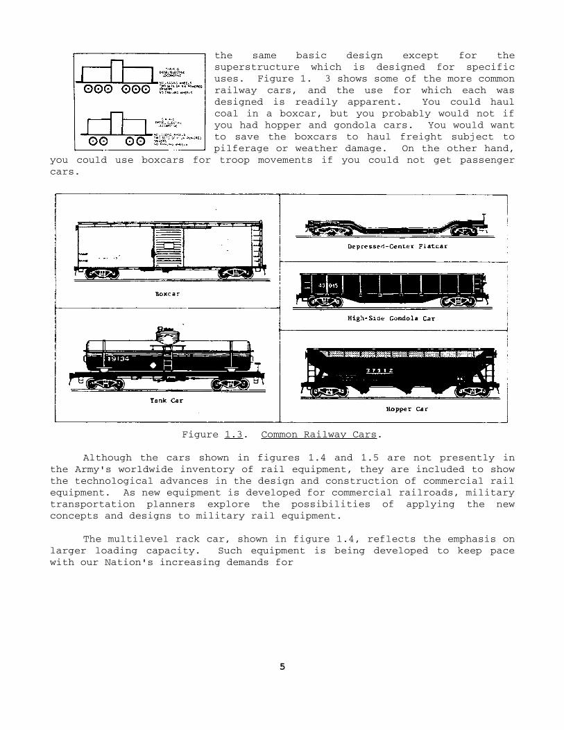
the same basic design except for thesuperstructure which is designed for specificuses. Figure 1. 3 shows some of the more commonrailway cars, and the use for which each wasdesigned is readily apparent. You could haulcoal in a boxcar, but you probably would not ifyou had hopper and gondola cars. You would wantto save the boxcars to haul freight subject topilferage or weather damage. On the other hand,
you could use boxcars for troop movements if you could not get passengercars.
Figure 1.3. Common Railway Cars.
Although the cars shown in figures 1.4 and 1.5 are not presently inthe Army's worldwide inventory of rail equipment, they are included to showthe technological advances in the design and construction of commercial railequipment. As new equipment is developed for commercial railroads, militarytransportation planners explore the possibilities of applying the newconcepts and designs to military rail equipment.
The multilevel rack car, shown in figure 1.4, reflects the emphasis onlarger loading capacity. Such equipment is being developed to keep pacewith our Nation's increasing demands for
5

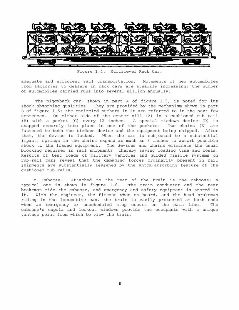
Figure 1.4. Multilevel Rack Car.
adequate and efficient rail transportation. Movements of new automobilesfrom factories to dealers in rack cars are steadily increasing; the numberof automobiles carried runs into several million annually.
The piggyback car, shown in part A of figure 1.5, is noted for itsshockabsorbing qualities. They are provided by the mechanism shown in partB of figure 1.5; the encircled numbers in it are referred to in the next fewsentences. On either side of the center sill (A) is a cushioned rub rail(B) with a pocket (C) every 12 inches. A special tiedown device (D) issnapped securely into place in one of the pockets. Two chains (E) arefastened to both the tiedown device and the equipment being shipped. Afterthat, the device is locked. When the car is subjected to a substantialimpact, springs in the chains expand as much as 8 inches to absorb possibleshock to the loaded equipment. The devices and chains eliminate the usualblocking required in rail shipments, thereby saving loading time and costs.Results of test loads of military vehicles and guided missile systems onrubrail cars reveal that the damaging forces ordinarily present in railshipments are substantially lessened by the shockabsorbing feature of thecushioned rub rails.
c. Caboose. Attached to the rear of the train is the caboose; atypical one is shown in figure 1.6. The train conductor and the rearbrakeman ride the caboose, and emergency and safety equipment is stored init. With the engineer, the fireman when on board, and the head brakemanriding in the locomotive cab, the train is easily protected at both endswhen an emergency or unscheduled stop occurs on the main line. Thecaboose's cupola and lookout windows provide the occupants with a uniquevantage point from which to view the train.
6

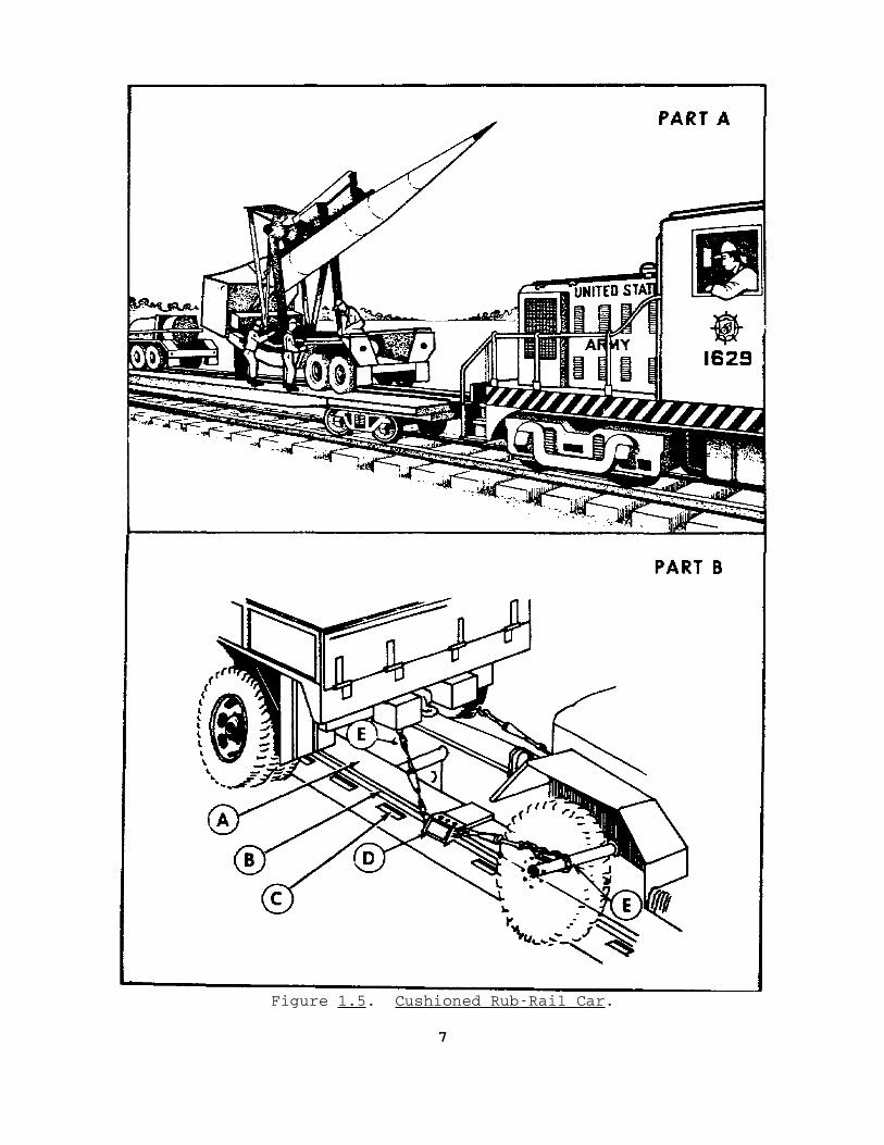
Figure 1.5. Cushioned RubRail Car.
7
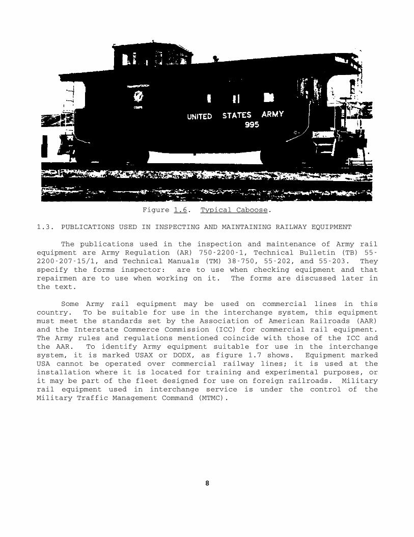
Figure 1.6. Typical Caboose.
1.3. PUBLICATIONS USED IN INSPECTING AND MAINTAINING RAILWAY EQUIPMENT
The publications used in the inspection and maintenance of Army railequipment are Army Regulation (AR) 75022001, Technical Bulletin (TB) 55220020715/1, and Technical Manuals (TM) 38750, 55202, and 55203. Theyspecify the forms inspector: are to use when checking equipment and thatrepairmen are to use when working on it. The forms are discussed later inthe text.
Some Army rail equipment may be used on commercial lines in thiscountry. To be suitable for use in the interchange system, this equipmentmust meet the standards set by the Association of American Railroads (AAR)and the Interstate Commerce Commission (ICC) for commercial rail equipment.The Army rules and regulations mentioned coincide with those of the ICC andthe AAR. To identify Army equipment suitable for use in the interchangesystem, it is marked USAX or DODX, as figure 1.7 shows. Equipment markedUSA cannot be operated over commercial railway lines; it is used at theinstallation where it is located for training and experimental purposes, orit may be part of the fleet designed for use on foreign railroads. Militaryrail equipment used in interchange service is under the control of theMilitary Traffic Management Command (MTMC).
8

Figure 1.7. Rail Cars With USAX and DODX Markings.
9

1.4. SUMMARY
The transportation railway service moves many tons of supplies andequipment to support a military mission in a theater of operations;therefore, most of the trains it operates are freight trains. The two basicArmy dieselelectric locomotives are the 0660, 120ton, 1,600horsepowerengine and the lighter 0440, 60ton, 400horsepower engine. Locomotivesare classified according to their wheel arrangement under the WhyteClassification System.
Each kind of Army railway car has basically the same design except forits superstructure which is designed for specific purposes. For example, aboxcar is suitable for carrying freight subject to pilferage or weatherdamage. If the need arises, however, a boxcar can be used to transportother types of freight or troops. The caboose at the rear of the train isused mainly to carry the train conductor and rear brakeman. Emergency andsafety equipment are also stored in it for use when accidents or breakdownsoccur on the road. Army rail equipment is inspected and maintainedaccording to regulations drawn up to correspond with rules prescribed by theICC and the AAR for commercial rail equipment. Army publications specifythe forms to be used in the inspection and maintenance of equipment.
Now that you have had a brief description of the three basic parts ofa trainthe locomotive, the rail cars, and the cabooseand a shortdiscussion on the publications governing the inspection and maintenance ofArmy rail equipment, the next chapter gives a detailed discussion of thedieselelectric locomotive.
10
Chapter 2 THE
DIESELELECTRIC
LOCOMOTIVE
2.1. INTRODUCTION
A dieselelectric locomotive is primarily a powerplant mounted onwheels with controls, whereby the power can be used to propel railwayequipment. Electrical equipment is used to transmit power from largeinternal combustion engines to the driving wheels. The powerplant consistsof one or two multicylinder engines which deliver from 150 to 1,600horsepower or more at a top speed of from 800 to 1,700 revolutions perminute (rpm). The engine is directly connected to a generator whichfurnishes the electrical power to the traction motors which drive thelocomotive through spur gears on the driving axles.
In the lines you have just read are mentioned a number of the majorcomponents of the dieselelectric locomotive, the subject of section I ofthis chapter. Discussed in section II is an important part of the overallmaintenance program for all types of rail equipmentpreventive maintenance.A sound preventive maintenance program greatly increases equipmentavailability and efficiency. Proper inspection and maintenance of Armydieselelectric locomotives help to keep them rolling. However, bothrequire completing various forms and records, the subject of section III.
Section I. Major Components
2.2. GENERAL
A modern dieselelectric locomotive is an assembly of many components;however, this section explains only its major oneswhat they are and howthey function. In the paragraphs to follow are discussed the engine itself,the three kinds of generators, the air compressor, the fuel and water tanks,and the trucks. As you study, refer often to figure 2.1 which illustrateshow the equipment on a dieselelectric locomotive is arranged. Also, referto the glossary in appendix H for explanations of technical terms that maybe unfamiliar to you.
11

Figure 2.1. Arrangement of Equipment of DieselElectric Locomotive.
12

2.3. DIESEL ENGINE
A diesel engine is an internal combustion, oilburning engine usingcompression ignition. Such an engine gets its power from the burning of acharge of fuel within a confined space called a cylinder. Ignition occurswhen the fuel is ignited solely by the heat of compression, caused byinjecting the fuel into the highly compressed, and thereby highly heated,air in the cylinder. A typical diesel engine designed for use in a dieselelectric locomotive is shown in figure 2.2. What are the advantages andfunction of this engine?
Figure 2.2. Diesel Engine.
a. Advantages. The principal economic advantage a diesel engine hasover other internal combustion engines is fuel economy. This results fromthe high compression ratio and the proportionately
13
higher expansion and thermal efficiency of the diesel. Its constant torquethroughout the speed range provides good pulling power at low speeds. Also,it performs well and is reliable in all kinds of weather. In addition, adiesel engine is much safer because its fuel is not as volatile as gasoline.And, too, the exhaust gases are not as dangerous as those of automobileengines because they are directed upward and dissipated into the atmosphere.
b. Function. The diesel engine changes heat energy into mechanicalenergy for turning a generator, to produce the electrical energy needed tooperate the traction motors supplying motive power. Some of the mechanicalenergy is also used to operate such auxiliary equipment of the locomotive asthe air compressor that supplies the air pressure for the airbrake system ofthe entire train.
2.4. GENERATORS
All dieselelectric locomotives have at least two generators, its mainand auxiliary ones, and sometimes a third, a steam generator. Theirfunctions are described in the subparagraphs following.
a. The main generator, such as the one shown in figure 2.3, convertsthe power output of the diesel engine into electrical power for operatingthe traction motors, discussed later in this subparagraph. Note the maingenerator's location on the locomotive, just forward of the engineman'scontrols, in figure 2.1 at the part numbered 12 and its blower, at the partnumbered 10.
The main generator is directly connected to the diesel engine whichturns the armature within the main field. With the generator directlyconnected to the diesel engine, the armature's speed varies with enginespeed between approximately 350 and 1,800 rpm for small engines and 300 to1,000 rpm for large engines. Even though the speed of rotation varies, themain fields are designed to produce up to 1,200 volts of direct current witha constant kilowatt output. The armature is built and balanced to withstandhighspeed rotation and all the vibrations incurred in operating with adiesel engine.
The traction motors receive electrical energy from the generator andconvert it to mechanical energy at the wheels of the locomotive. The motorsare geared to the locomotive axles, and, by driving the axles and turningthe wheels, they supply the locomotive's tractive effort. The motors aremounted on the axles in the trucks of the locomotive.
14
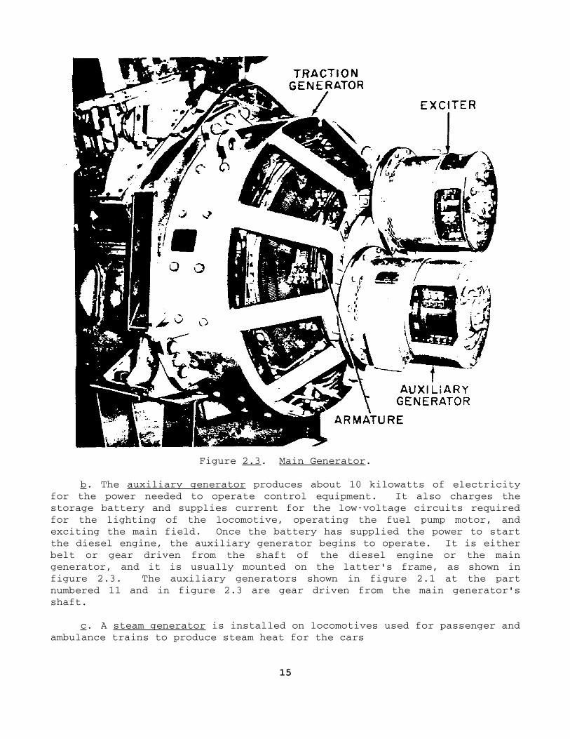
Figure 2.3. Main Generator.
b. The auxiliary generator produces about 10 kilowatts of electricityfor the power needed to operate control equipment. It also charges thestorage battery and supplies current for the lowvoltage circuits requiredfor the lighting of the locomotive, operating the fuel pump motor, andexciting the main field. Once the battery has supplied the power to startthe diesel engine, the auxiliary generator begins to operate. It is eitherbelt or gear driven from the shaft of the diesel engine or the maingenerator, and it is usually mounted on the latter's frame, as shown infigure 2.3. The auxiliary generators shown in figure 2.1 at the partnumbered 11 and in figure 2.3 are gear driven from the main generator'sshaft.
c. A steam generator is installed on locomotives used for passenger andambulance trains to produce steam heat for the cars
15


in cold weather. It is an independent, oilfired heating unit that operatesautomatically once it has been started, In figure 2.1, the steam generatoris the part numbered 2.
2.5. AIR COMPRESSOR
An air compressor, such as the one shown in figure 2.4, compresses theair used to operate much of the equipment on a dieselelectric locomotive.Such equipment includes airbrake systems, reversers, electropneumaticcontactors, sanders, and window wipers. The compressor may be engine driveneither directly by belts from the main generator's shaft or through aflexible coupling to it. The air compressor has a twocompression cycle.Two
Figure 2.4. Air Compressor.
16
lowpressure cylinders compress air which then passes through a coolingsystem to a highpressure cylinder that compresses it still further beforefeeding the air to the main reservoir. This reservoir is kept at a pressureof 125 to 140 pounds.
2.6. TANKS
Both fuel and water tanks are carried on a dieselelectric locomotive.The fuel tank, usually suspended beneath the underframe between trucks,contains fuel oil for operating the diesel engine. Note the parts numbered35 and 36 on figure 2.1. A waterexpansion tank containing water forcooling the engine is located at the highest point in the enginecoolingwater system, the part numbered 19 on figure 2.1. This system is designedto carry away and disperse the excess heat generated in the engine.
2.7. TRUCKS
The main function of the trucks is to provide a connection between theaxles and wheels and the locomotive itself. The trucks must carry theweight of the locomotive superstructure and distribute it through the wheelsto the rails. They also absorb lateral thrusts and ride over uneven railswithout excessively tilting and swaying the locomotive. The trucks alsoprovide mountings for the brake rigging and traction motors.
Army dieselelectric locomotives have either two 6wheel swivel 3motor trucks or two 4wheel swivel 2motor trucks. Figure 2.5 shows a 4wheel swivel 2motor truck used on the 0440 dieselelectric locomotive.The main difference between the 4wheel and the 6wheel truck is that theweight of the locomotive is distributed over a wider surface by a 6wheelone; therefore, it has a greater working surface on the rails, giving thelocomotive more tractive effort or pulling power.
2.8. SUMMARY
A dieselelectric locomotive is made up of many complex parts. Isinternal combustion diesel engine burns diesel fuel oil ignited by the heatof compressed air within a cylinder, a process known as compressionignition. The main generator is connected to the engine, and its mechanicalenergy output turns the generator to produce the electric current needed topower the traction motors that turn the locomotive's wheels.
17
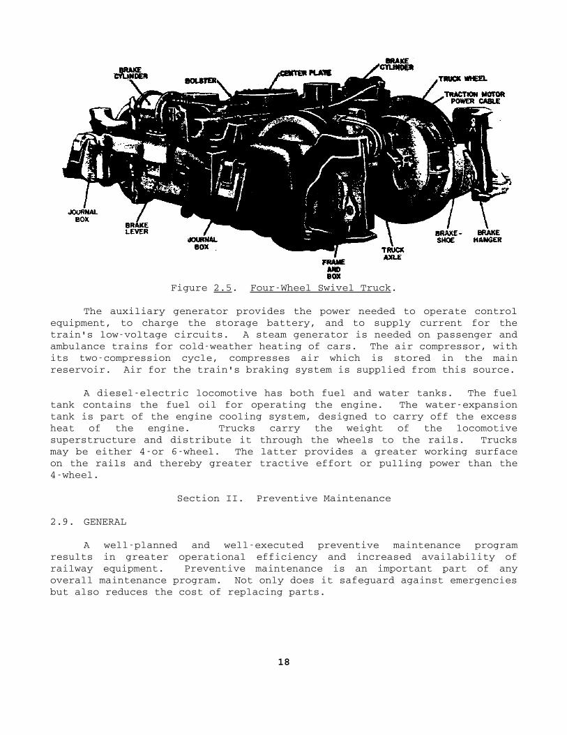
Figure 2.5. FourWheel Swivel Truck.
The auxiliary generator provides the power needed to operate controlequipment, to charge the storage battery, and to supply current for thetrain's lowvoltage circuits. A steam generator is needed on passenger andambulance trains for coldweather heating of cars. The air compressor, withits twocompression cycle, compresses air which is stored in the mainreservoir. Air for the train's braking system is supplied from this source.
A dieselelectric locomotive has both fuel and water tanks. The fueltank contains the fuel oil for operating the engine. The waterexpansiontank is part of the engine cooling system, designed to carry off the excessheat of the engine. Trucks carry the weight of the locomotivesuperstructure and distribute it through the wheels to the rails. Trucksmay be either 4or 6wheel. The latter provides a greater working surfaceon the rails and thereby greater tractive effort or pulling power than the4wheel.
Section II. Preventive Maintenance
2.9. GENERAL
A wellplanned and wellexecuted preventive maintenance programresults in greater operational efficiency and increased availability ofrailway equipment. Preventive maintenance is an important part of anyoverall maintenance program. Not only does it safeguard against emergenciesbut also reduces the cost of replacing parts.
18

Although the weight of dieselelectric locomotives ranges upward from25 tons and their horsepower from 150, the same general preventivemaintenance procedures apply to all of them. Some of the importantpreventive maintenance checks on dieselelectric locomotives are discussedin this section; however, they are not allinclusive. No satisfactorysubstitute has ever been found for commonsense; no conscientious equipmentoperator or inspector limits his inspection to any set checklist. He isconstantly alert for any defects in his equipment and for any sign thatleads him to believe it may be developing defects. For example, if alocomotive engineer observes a defective electric wire, he would not attemptto operate his locomotive until the defect has been checked thoroughly andany necessary repairs made. The checkpoints given here are only a guide togood preventive maintenance. The five paragraphs to follow discuss the oil,water, fuel, air pressure, and commutator checkpoints to be inspected. Thenthe next three paragraphs, in turn, discuss the engine overspeed trip, theground relay, and the end receptacles.
2. 10. OIL CHECKPOINTS
The oil level in the diesel engine and the pressure of that oil mustbe checked as well as the oil level in the engine governor and in the aircompressor. Details are given in the subparagraphs following.
Figure 2.6. Engine LubricationDipstick.
a. Oil level in the diesel engine. Check the oil level in thediesel engine by using the bayonetshaped dipsticks located on eitherside of the engine. The locationand markings on one of thedipsticks are shown in figure 2.6.When the engine has been stoppedfor 30 minutes or more, most of theoil will have drained to the bottomof the engine; at that time, theoil level shown on the dipstickshould be above the full mark.With the engine idling, the oil ishot and circulating through theengine, and a reading taken at thattime should show the oil level onthe dipstick between low and full.
19


b. Lubricating oil pressure gage. The diesel engine lubricatingsystem's oil pressure gage is located in the locomotive cab. Observe thegage frequently while the locomotive is being operated; investigate anydeviation from normal readings. Improper oil pressure causes excessiveengine wear and possible engine breakdown.
c. Lubricating oil supply in engine governor. The engine is equippedwith a governor to regulate its speed according to various throttlesettings. This is done by altering the amount of fuel introduced into thecylinder. The governor has its own oil lubricating system. Figure 2.7shows the oil level sight gage on one type of engine governor. This gagehas two marks; the oil level should be between them for safe operation.
Figure 2.7. Engine Governor Oil Level Sight Gage.
20


d. Lubricating oil supply inair compressor. As discussed inparagraph 2.5, the air compressoris needed to operate a great dealof the equipment on the locomotive;it has its own oil pumps andpressure lubricating system. Whenthe engine is stopped, the oillevel in the compressor crankcaseis checked with a bayonetshapeddipstick, located as shown infigure 2.8. The level should bebetween the low and high marks.
Figure 2.8. Location of AirCompressor LubricationDipstick.
2.11. WATER CHECKPOINTS
The Army's dieselelectric locomotives have watercooled engines. Incarrying out preventive maintenance procedures, both the level andtemperature of the water must be checked. Subparagraphs a and b give thedetails.
Figure 2.9. Water reservoirand Marked Gage.
a. Level. The water used tocool the diesel engine is stored ina reservoir equipped with a gage.Figure 2.9 shows the markings on atypical one. The water levelshould be between low and full atone of the readings, depending uponwhether the engine is running orstopped. The engine should not beoperated if no water appears in thegage.
b. Temperature. The enginewater temperature gage, located inthe locomotive cab, shows thetemperature of the water in the
engine cooling system. Recommended operating temperatures on differentlocomotive models vary. On one, the range is from 160° to 170° F.; onanother, from 175° to 180° F. After the engine of the latter model isstarted, it is idled until the temperature is normal120° F. or morebefore pulling any cars.
21


2.12. FUEL CHECKPOINTS
Each locomotive has at least two fuel checkpoints to be inspectedbefore operating the engine. They are the fuelflow glasses and the fuelcutoff valve, discussed in the subparagraphs to follow.
a. Flow. Located on theduplex filter assembly are twofuelflow sight glasses. The fuelflow in the right glass, the onenearest the engine, should be clearand free of bubbles for properengine operation. Figure 2.10shows the duplex filter assemblyand the two fuelflow glasses.
b. Cutoff valve. In anemergency or by accident, the fuelcutoff valve can be tripped by apull cord to stop the supply offuel to the engine. Whenever thevalve is tripped, it must be reset;it must be open for the engine tooperate. Look at figure 2.11. Theyoke normally holds the valve open,but when the lever is raised, theyoke also comes up, depresses thevalve stem, and stops the fuelflow. To reset the valve, thelever is depressed, making the yokeslide into place and raise thevalve stem. Fuel is once moreflowing into the engine.
Figure 2.10. Duplex Fuel FilterAssembly.
Figure 2.11. Fuel Cutoff Valve.
22


2.13. AIR PRESSURE CHECKPOINTS
Control or instrument panels containing the many different gages andswitches may be located at different places in the locomotive cab. Theirarrangement may vary with each dieselelectric locomotive, but they arealways in a conspicuous place. The instrument panel normally contains twoair gages, one to show the air pressure in the main reservoir and the otherto show the air pressure in the brake pipe and cylinder. The gages aretested once every 3 months and whenever any irregularity is noted. Anaccurate test gage or deadweight tester is used in making the test; any airgage found incorrect is repaired before being used again.
2.14. COMMUTATOR CHECKPOINTS
The main generator is turned by a direct drive connection with thediesel engine. The electric current that the generator produces is passedfrom the commutator through brushes and into the locomotive electrical powersystem. Figure 2.12 shows the alternator slip rings for a.c. power to roofcooling fans and traction motor blowers, with brushes and brush holders inplace. Proper generator or alternator operation and electrical outputdepend upon the commutator or slip rings being clean and free of defects,the brush holders being correctly positioned, and the brushes being free ofexcessive wear. The commutator or slip rings are inspected for cleanliness;no oil, carbon deposits, or dirt should accumulate on either; and thesegments of the rings should not be nicked or cracked or show burned orblackened spots. If the plates are defective, repairs should be made beforethe locomotive is operated. The brush holders should be securely in placeand positioned 1/8 inch above the commutator or slip rings. The brushescontained by the brush holders should ride evenly on the commutator or sliprings; if they show excessive wear, they should be replaced. If dirt orcarbon is permitted to accumulate on the brush holders, a short circuit mayoccur. If the brushes are worn excessively or are defective, an opencircuit may occur. The same preventive maintenance inspection should bemade of the auxiliary generator; one is shown in figure 2.13. In thisillustration, the inspection plate has been removed to reveal a brush holderand brush.
2.15. ENGINE OVERSPEED TRIP MECHANISM
When the diesel engine's speed becomes excessive, an overspeed tripmechanism located in the cab stops the engine by preventing further fuelinjection into the cylinders. The resetting procedure varies with differentlocomotives. Some trip mechanisms are reset
23

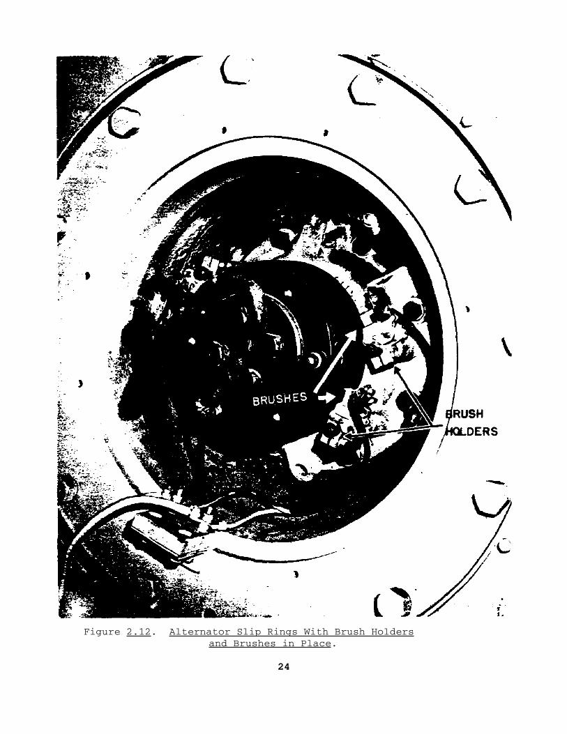
Figure 2.12. Alternator Slip Rings With Brush Holdersand Brushes in Place.
24

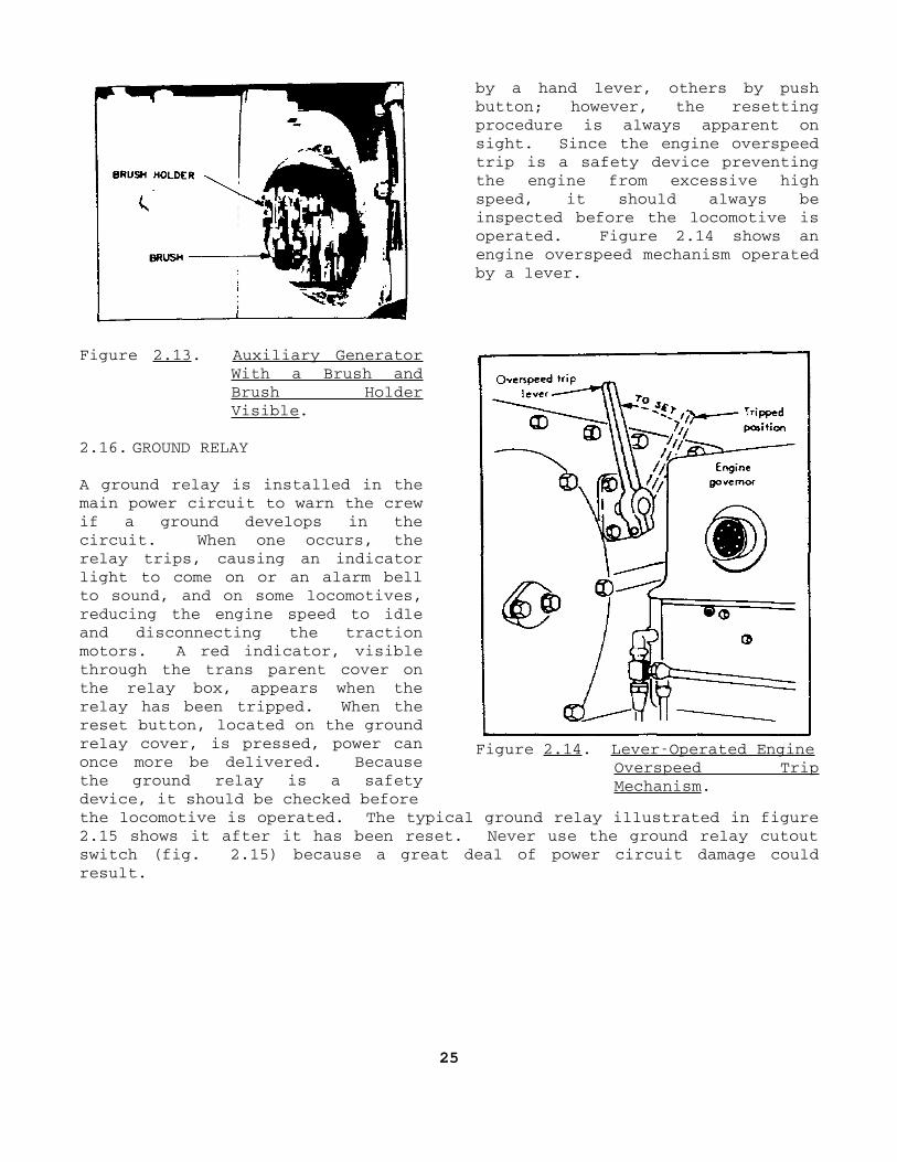
by a hand lever, others by pushbutton; however, the resettingprocedure is always apparent onsight. Since the engine overspeedtrip is a safety device preventingthe engine from excessive highspeed, it should always beinspected before the locomotive isoperated. Figure 2.14 shows anengine overspeed mechanism operatedby a lever.
Figure 2.13. Auxiliary GeneratorWith a Brush andBrush HolderVisible.
2.16. GROUND RELAY
A ground relay is installed in themain power circuit to warn the crewif a ground develops in thecircuit. When one occurs, therelay trips, causing an indicatorlight to come on or an alarm bellto sound, and on some locomotives,reducing the engine speed to idleand disconnecting the tractionmotors. A red indicator, visiblethrough the trans parent cover onthe relay box, appears when therelay has been tripped. When thereset button, located on the groundrelay cover, is pressed, power canonce more be delivered. Becausethe ground relay is a safetydevice, it should be checked before
Figure 2.14. LeverOperated EngineOverspeed TripMechanism.
the locomotive is operated. The typical ground relay illustrated in figure2.15 shows it after it has been reset. Never use the ground relay cutoutswitch (fig. 2.15) because a great deal of power circuit damage couldresult.
25

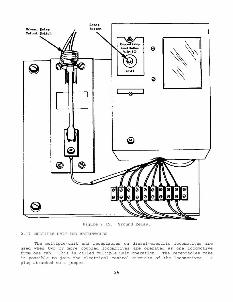
Figure 2.15. Ground Relay.
2.17. MULTIPLEUNIT END RECEPTACLES
The multipleunit end receptacles on dieselelectric locomotives areused when two or more coupled locomotives are operated as one locomotivefrom one cab. This is called multipleunit operation. The receptacles makeit possible to join the electrical control circuits of the locomotives. Aplug attached to a jumper
26

Figure 2.16. MultipleUnit EndReceptacle.
containing the control wires isinserted in the end receptacle tomake the connection. Each endreceptacle should be inspected forcracks in the insulation, bent orbroken contact pins, and brokencover springs. Figure 2.16pictures a typical multipleunitend receptacle; note the 27 contactpins.
2.18. SUMMARY
An effective preventivemaintenance program is necessary toguard against breakdown ofequipment and reduce the expenseinvolved in replacing parts.Although checklists and guidelinesmay be provided for makingpreventive maintenance inspections,a good inspector does not limithimself to a set list but observeshis equipment keenly for any sign
of developing defects. A locomotive operator, for example, observes theinstrument panel in the cab containing the various gages and controls. Theyinclude air pressure gages, oil pressure gages in the engine lubricatingsystem, and water temperature gages. Excessive deviations from normalreadings on the gages may point out deficiencies that could develop intoserious defects.
Section III. Inspection and Maintenance Forms
2.19. GENERAL
Publications governing the inspection and maintenance of Army dieselelectric locomotives require the use of various forms and records. Thissection contains only a general discussion of them. For details onpreparation and distribution, the units responsible for inspecting andmaintaining the equipment must have the appropriate publications on hand andfollow the instructions therein. Technical Manual 38750, The ArmyMaintenance Management System (TAMMS), and Technical Manual 55202,Operation and Maintenance of DieselElectric Locomotives, are the twoneeded.
27

2.20. MAINTENANCE REQUEST
The Maintenance Request, DA Form 2407, shown in figure 2.17, isdesigned to provide maintenance information to all management levels. Onrailway equipment, it is used to submit equipment improvementrecommendations (EIR), report modification work orders (MWO) accomplished,and record maintenance requested and accomplished. The 2407, a multiplecopy form, has copies designated as follows: receipt, national maintenancepoint (NMP), control, organization, and file. All but the receipt copy havethree sections each: maintenance request, work accomplished and equipmentimprovement recommendations. The receipt copy has sections I and III onlywith instructions for using the form at the various maintenance levelsinstead of section II. On the back of the file copy are some of the codesused in preparing the form; the complete list of codes and an explanation ofsome of them are given in appendix A of TM 38750.
Figure 2.17 is an illustration of the DA Form 2407 with only section Icompleted. The requesting organization fills out this section and sends theform, along with the equipment, to the support activity. After the repairsare finished, the support activity completes section I and returns theequipment to the requesting agency.
2.21. EQUIPMENT DAILY OR MONTHLY LOG
As implied by the title, DA Form 24081, Equipment Daily or MonthlyLog, serves two purposes. It provides both a daily and a monthly record ofinformation relating to the operation of equipment. All Army dieselelectric locomotives have two 24081 forms in their log booksone for adaily log, as shown in figure 2.18, and one for a monthly log, as shown infigure 2.19. Each is discussed in the following subparagraphs.
a. The daily log shows a daytoday record for a month of the hours thelocomotive was operated, the fuel and lubricants added during operation, andthe number of days the locomotive was deadlined. At the end of each day'soperation, the engineman inspects the locomotive and then makes the entriesin columns a through g on form 24081. At the end of each month,information in columns b, c, d, and h of the daily log is compiled andentered on the 24081 monthly log. The daily log is retained for 90 daysand then destroyed.
b. The monthly log is a compilation of information taken from the dailylog. The entries on the monthly log give the total hours
28
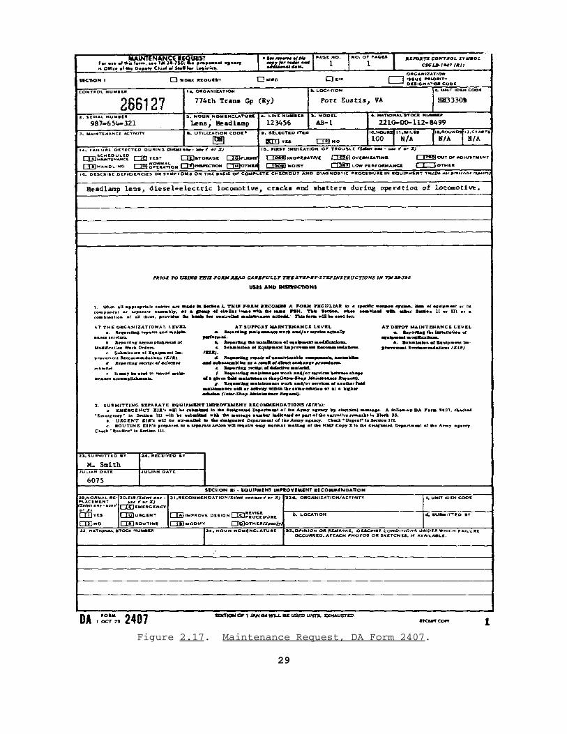
Figure 2.17. Maintenance Request, DA Form 2407.
29

Figure 2.18. Equipment Daily Log, DA Form 24081.
Figure 2.19. Equipment Monthly Log, DA Form 24081.
the locomotive was operated during the month, total fuel and lubricantsadded, and total number of days the locomotive was nonoperational. The24081 monthly log is a permanent record; it is not destroyed.
30

2.22. EQUIPMENT MODIFICATION RECORD
The DA Form 24085, Equipment Modification Record, is used to recordthe requirements for and the application of all authorized modifications ofequipment. As shown in figure 2.20, the form is divided into two majorsections: modifications required (block 4), and modifications completed(block 5). Information on required modifications is transcribed from a DAModification Work Order (MWO) or other modification directive to the block 4section of the form by the equipment owner. Information relating tocompletion of the modification is entered in block 5 by the activity makingthe modification.
Figure 2.20. Equipment Modification Record, DA Form 24085.
2.23. AIR BRAKE INSPECTION REPORT FOR LOCOMOTIVES AND LOCOMOTIVE CRANES
The Air Brake Inspection Report for Locomotives and Locomotive Cranes,DA Form 4171R, is designed to determine the condition of the air brakeequipment and insures compliance with regulations of the Federal RailroadAdministration, Department of Transportation. The form, shown in figure2.21, is used to record the inspection, cleaning, servicing, and repair ofair brake components at least every 6 months or as indicated on the form.It is prepared in duplicate, and the individual performing the service ormaintenance records the appropriate dates of inspection and repair.
31

The repair and testing are performed at DS/GS level. The officer in chargecountersigns the form. The original copy of the form is placed under atransparent cover in the locomotive cab; the other copy is retained by theusing unit. The completed forms are retained until the next scheduled airbrake inspection and testing and then destroyed.
Figure 2.21. Air Brake Inspection Report for Locomotives and LocomotiveCranes, DA Form 4171R.
2.24. DAILY INSPECTION WORKSHEET FOR DIESELELECTRIC LOCOMOTIVES
In addition to the forms just discussed, DD Form 862, Daily InspectionWorksheet for DieselElectric Locomotives, is used in performing the dailyinspection and maintenance of the locomotive. Figure 2.22 shows the front ofthe 862, and figure 2.23 the back.
In making the daily inspection, a visual check and an operational testrun of the locomotive are performed each day it is in service. The DD Form862 is filled out by both the locomotive engineer and the maintainer orinspector. It is divided into sections A, B, C, and D. Section A, or theoperator's report, is filled out by the locomotive engineer. He operatesthe locomotive and notes
32


Figure 2.22. Daily Inspection Worksheet for DieselElectricLocomotives, DD Form 862, (Front).
33

Figure 2.23. Daily Inspection Worksheet for DieselElectricLocomotives, (Back).
34

any faults. At the bottom of section A are nine items that he checks, ifapplicable to his locomotive, before he goes off duty. He turns in the 862to the railway equipment company (B company). An inspector makes the checksin section B, as shown in figure 2.22, and a mechanic corrects the faultsnoted and places his initials in the column headed Corrected. The mechanicuses section C to list faults he was unable to correct, if necessary. Aninspector then examines the work of the mechanic to insure that it has beendone correctly and signs the form in the proper space in section D. Theforeman, or commander of the railway equipment company, also signs the formin the space provided in section D. The 862's are then filed and kept untilthe monthly inspection is made, at which time all the daily forms aredestroyed.
2.25. INSPECTION AND REPAIR REPORT OF LOCOMOTIVES AND LOCOMOTIVE CRANES
The Inspection and Repair Report of Locomotives and Locomotive Cranes,DD Form 1336, is used for monthly and annual inspections. Figure 2.24 showsit completed for a monthly inspection. Figure 2.25 shows it completed foran annual inspection. This report establishes the condition of locomotivesand locomotive cranes
Figure 2.24. Inspection and Repair Report of Locomotives andLocomotive Cranes (Monthly), DD Form 1336.
35

Figure 2.25. Inspection and Repair Report of Locomotives andLocomotive Cranes (Annual), DD Form 1336.
36

to determine compliance or noncompliance with Federal Railway Administration(FRA), Department of Transportation (DOT), regulations. It also shows themaintenance and repairs needed to comply with FRA, DOT regulations. Thisdualpurpose form (30day and annual) is used to record and report theconditions and maintenance requirements resulting from the daily inspections(par. 2.24). Also, the annual report is to be completed after each depotoverhaul. Items on the 30day report are to be recorded by qualifiedorganizational level personnel. The annual report is to be prepared intriplicate by qualified DS, GS, or depot level personnel. The inspectorsigns the form. The officer in charge countersigns it. "Condition" is tobe shown as "good", "fair", or "bad". When 'bad" is used, it indicates thatthe part or parts are not in a safe or suitable condition or are inviolation of regulations.
2.26. SUMMARY
The inspection and maintenance of Army equipment locomotives requirethat certain forms and records must be completed. Among other things, theyare used to record both scheduled and performed preventive maintenance, loadtests, equipment faults, and criteria tests and checks; to request direct orgeneral support maintenance; to record the accomplishment of a maintenancework order; to submit an equipment improvement recommendation; and tocollect maintenance data.
The forms used for inspection and maintenance of dieselelectriclocomotives include the Maintenance Request, DA Form 2407; Equipment Dailyor Monthly Log, DA Form 24081; Equipment Modification Record, DA Form 24085; Daily Inspection Worksheet for Diesel Electric Locomotives, DD Form 862;and Air Brake Inspection Report for Locomotives and Locomotive Cranes, DAForm 4171R.
The maintenance request is used to request maintenance andmodifications to locomotives and to record them when accomplished. The DAForms 24081 and 24085, a part of the locomotives historical records,record daily and monthly usage and maintenance of a locomotive and itsrequirements for and application of all authorized modifications. The DDForm 862 is used in the daily inspection and maintenance of the locomotiveand the DA Form 4171R for recording the condition of the locomotive's airbrake equipment and the maintenance performed to bring it up to FederalRailway Administration standards.
37
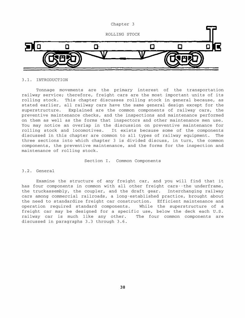
Chapter 3
ROLLING STOCK
3.1. INTRODUCTION
Tonnage movements are the primary interest of the transportationrailway service; therefore, freight cars are the most important units of itsrolling stock. This chapter discusses rolling stock in general because, asstated earlier, all railway cars have the same general design except for thesuperstructure. Explained are the common components of railway cars, thepreventive maintenance checks, and the inspections and maintenance performedon them as well as the forms that inspectors and other maintenance men use.You may notice an overlap in the discussion on preventive maintenance forrolling stock and locomotives. It exists because some of the componentsdiscussed in this chapter are common to all types of railway equipment. Thethree sections into which chapter 3 is divided discuss, in turn, the commoncomponents, the preventive maintenance, and the forms for the inspection andmaintenance of rolling stock.
Section I. Common Components
3.2. General
Examine the structure of any freight car, and you will find that ithas four components in common with all other freight carsthe underframe,the truckassembly, the coupler, and the draft gear. Interchanging railwaycars among commercial railroads, a longestablished practice, brought aboutthe need to standardize freight car construction. Efficient maintenance andoperation required standard components. While the superstructure of afreight car may be designed for a specific use, below the deck each U.S.railway car is much like any other. The four common components arediscussed in paragraphs 3.3 through 3.6.
38

3.3. UNDERFRAME
The rail car underframe is the framework that receives the shock andpulling stresses to which the car is subjected when it is being moved overthe railroad. It supports the deck and superstructure of the car andcarries the weight of the load in the car. Figure 3.1 shows the underframeconstruction of a typical freight car, viewed from the bottom, to show thebody bolster center plates. What are the most important parts of theunderframe? They are the center sill, body bolsters, draft gear pockets,side sills, end sills, and floor stringers; they are discussed in thesubparagraphs following.
Figure 3.1. Underframe.
a. The center sill is a longitudinal structural member that forms thebackbone of the underframe. It supports the other members of the underframeand transmits the pushandpull stress
39

throughout the length of the car. It contains the couplers and draft gearsin pockets at either end.
b. The body bolsters are transverse members of the car underframelocated over the center of the trucks. Resting on the truck bolsters, theytransmit the weight carried by the center sill to the trucks through themated body bolster and truck bolster center plates. The body bolsterscontain side bearings that steady the car and prevent excessive rockingwhile it is in motion.
c. The draft gear pockets are the receptacles located at either end ofthe center sill that receive the draft gear and couplers. The strikingplates or castings are part of the coupler and draft gear arrangement. Thedraft gear is discussed further in paragraph 3.6.
d. Other members required to complete the underframe are side sills,end sills,. and floor stringers. They provide the tremendous strengthnecessary for railway car operation and the mounts for the decking thatcarries the load. These members are identified in the inserted sketch.
3.4. TRUCK ASSEMBLY
The wheeled assemblies at each end of the car are called trucks. Eachmay have one, two, or more pairs of wheels. Most freight equipment in theUnited States has 4wheel trucks. Railway cars and dieselelectriclocomotives use the same type of truck assemblies, discussed in paragraph2.7. The trucks support the underframe and superstructure; they swivelenough to ride the rails and negotiate curves readily. An important featureof these assemblies is that the essential parts most likely to requirerepair or replacement are easily reached. A typical freight car truck isshown in figure 3.2. Study it as you read the following subparagraphs inwhich some of the assembly's parts are discussed.
40
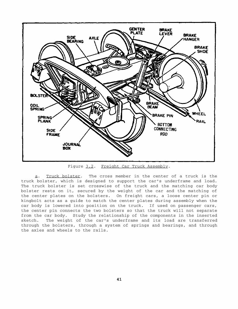
Figure 3.2. Freight Car Truck Assembly.
a. Truck bolster. The cross member in the center of a truck is thetruck bolster, which is designed to support the car's underframe and load.The truck bolster is set crosswise of the truck and the matching car bodybolster rests on it, secured by the weight of the car and the matching ofthe center plates on the bolsters. On freight cars, a loose center pin orkingbolt acts as a guide to match the center plates during assembly when thecar body is lowered into position on the truck. If used on passenger cars,the center pin connects the two bolsters so that the truck will not separatefrom the car body. Study the relationship of the components in the insertedsketch. The weight of the car's underframe and its load are transferredthrough the bolsters, through a system of springs and bearings, and throughthe axles and wheels to the rails.
41

b. Side frame. On the outside of the truck wheels is the side frame;it extends from one axle to the other and forms the side of the truck. Thetwo side frames on each truck contain sets of coil springs upon which thetruck bolster sits. The springs distribute the car's weight equally throughthe side frames onto the axle journals located at each end of the sideframes.
c. Wheel and axle assembly. A combination of two axles and four wheelsmake up a wheel and axle assembly for a general freight car. Each axle hastwo wheels that are pressed upon the axle under pressure ranging from 70 to150 tons. For some passenger equipment and highspeed freight cars,however, the wheel and axle assembly consists of three axles and six wheels.But on either the general or the other types of freight cars, the ends ofthe axles or journals are highly polished and extend into journal boxes, toprovide a working surface for the bearings and a means for lubricating theaxle and bearing.
d. Brake rigging. The cylinder, piston, rods, and levers necessary totransmit air pressure to the brakeshoes and wheels are included in the brakerigging. Each car has an independent braking system, powered by compressedair supplied by a compressor located on the locomotive.
e. Journal box. An important component of the truck assembly is thejournal box; it encloses the bearing and wedge assembly, the axle journal,and necessary waste packing or lubricator pad, and lubricant. One box islocated at each end of each axle. They require more maintenance than anyother part of a railway car. The journal boxes provide for the lubricationof the axles and bearings. A typical journal box assembly, shown in figure3.3, contains the components described next.
42

Figure 3.3. Journal Box Assembly With Friction Bearing.
(1) Journalend of the axle, or the part of an axle on which thejournal bearing rests.
(2) Waste packingcushioning made of fibrous material placed in thebottom of the journal box. Saturated with a lubricant, the packing feedsthe lubricant to the journal and bearing. A commercial springtypelubricator pad has been substituted for waste packing on most U.S.commercial railroads.
(3) Wedgeholds the bearing in place and distributes weight from theside frame to the journals, through the wheels, to the rails.
(4) Bearingdevice that provides a smooth working surface againstthe journal. The friction bearing is a brass casting with a babbitt lining.It transfers friction heat to the top of the journal box through which itescapes to the atmosphere by the passage of cool air over the journal box.
43
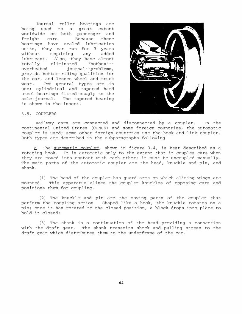
Journal roller bearings arebeing used to a great extentworldwide on both passenger andfreight cars. Because thesebearings have sealed lubricationunits, they can run for 3 yearswithout requiring any addedlubricant. Also, they have almosttotally eliminated 'hotbox"overheated journalproblems,provide better riding qualities forthe car, and lessen wheel and truckwear. Two general types are inuse: cylindrical and tapered hardsteel bearings fitted snugly to theaxle journal. The tapered bearingis shown in the insert.
3.5. COUPLERS
Railway cars are connected and disconnected by a coupler. In thecontinental United States (CONUS) and some foreign countries, the automaticcoupler is used; some other foreign countries use the hookandlink coupler.Both types are described in the subparagraphs following.
a. The automatic coupler, shown in figure 3.4, is best described as arotating hook. It is automatic only to the extent that it couples cars whenthey are moved into contact with each other; it must be uncoupled manually.The main parts of the automatic coupler are the head, knuckle and pin, andshank.
(1) The head of the coupler has guard arms on which alining wings aremounted. This apparatus alines the coupler knuckles of opposing cars andpositions them for coupling.
(2) The knuckle and pin are the moving parts of the coupler thatperform the coupling action. Shaped like a hook, the knuckle rotates on apin; once it has rotated to the closed position, a block drops into place tohold it closed:
(3) The shank is a continuation of the head providing a connectionwith the draft gear. The shank transmits shock and pulling stress to thedraft gear which distributes them to the underframe of the car.
44

Figure 3.4. Automatic Coupler.
b. The hookandlink coupler, the kind used on some Army railway carsto be operated in foreign countries, is equipped with a draw hook andturnbuckle. Each car has a hook, a connecting link, and a pair of endbuffers. Figure 3.5 shows two railway cars with hookandlink couplersconnected. To couple the cars, they are pushed together and the connectinglink placed over the opposing hook. Then the links are tightened by theturnbuckle, and all slack is taken up between the cars. The end buffers arespring loaded to absorb the shock of coupling and to keep the car bodiesfrom striking each other.
3.6. DRAFT GEAR
Located at each end of a car is a draft gear that connects the couplerto the underframe and absorbs the coupling shock and the shock of increasesin train speed or pulling stresses. Most Army rolling stock is equippedwith a friction draft gear. Figure 3.6 shows three different types.Fitting into a pocket in the underframe, the draft gear distributes thecoupling shock over the car underframe. The location of the draft gearpocket can be see in figure 3.1. In most theaters of operations, the draftgear of railway cars is designed
45

Figure 3.5. Two Railway Cars With HookandLink CouplersConnected.
to absorb pulling stresses only, whereas coupling shock is absorbed bybuffers set approximately 35 inches to each side of the centerline of thedraft gear. The buffers are labeled in figure 3.5.
3.7. SUMMARY
Interchanging cars among commercial railroads has brought about thestandardization of rail car components to achieve efficient operation andmaintenance. With the exception of the superstructure, the design of allrailway cars is generally the same. Some of their componentsunderframe,truck assembly, couplers, and draft gearare common to all rail equipment.The underframe receives the shock and pulling stresses of the moving car,supports the car's deck and superstructure, and carries the weight of thecargo. The truck assembly is the wheeled assembly at each end of the carwhich
46

Figure 3.6. Friction Draft Gears.
supports the underframe and superstructure. To connect two cars, a coupleris used. An automatic one is used in the United States and in some overseaareas while the hookandlink coupler is common in others. The draft gearjoins the coupler to the underframe and absorbs the coupling shock as wellas that which comes from sudden acceleration or from pulling stresses.
Section II. Preventive Maintenance
3.8. GENERAL
The various designs of railway car superstructures serve manypurposes, but the major components and the preventive maintenance on themare the same. This is generally true for rolling stock found in theaters ofoperations. Preventive maintenance on railway cars is important because itincreases the availability of this equipment and decreases the possibilityof breakdowns. Inadequate maintenance ties up equipment in repair tracksand shops and decreases rail transport capability.
Of all the components of railway equipment, the truck assembliesreceive the greatest amount of maintenance and require the most attention.
The preventive maintenance checks of the truck assembly can be dividedinto four groups: the general truck assembly, truck brake rigging, journalboxes, and wheels. They are discussed in the next
47


four main paragraphs. As you study them, refer to figure 3.2 where theparts of a typical truck assembly are labeled. Maintenance of safetyappliances is discussed briefly in paragraph 3.13.
3.9. GENERAL TRUCK ASSEMBLY
The general truck assembly should be inspected overall for defective,cracked, or broken parts. Other than the journal boxes, the only part ofthis assembly that needs lubrication is the wearing area of the centerplate. The truck center plate provides a recess for the center pin and awearing surface to match the wearing surface of the body center plate. Thisconnection between the truck and the car underframe allows the truck toswivel beneath the rigid car underframe to permit the car to negotiatecurves properly. The center plate should always be well lubricated with aheavy, tacky, or graphited lubricant applied with a paddle. Normally, nogrease fittings are provided for lubricating the center plate.
3.10. BRAKE RIGGING
Although not all of the brake rigging is located on the truck, most ofthe mechanical parts are attached to it. Generally the same kinds of brakeparts are used on all trucks, and they should be inspected closely toprevent the necessity for heavy maintenance and increase the performance ofthe equipment. The following subparagraphs discuss preventive maintenanceindicators on the truck brake rigging.
a. Brakeshoe. The part of the brake rigging that actually performs thebraking action is the brakeshoe. When the brakes are applied, the shoe ispushed against the wheel tread causing a great increase in the frictionresistance to the roll of the wheel. Until recently, brakeshoes were madeof cast iron, and many of them are still in use. However, since they causesparking, they are gradually being replaced by composition shoes that lastlonger and eliminate the danger of causing fires. The shoe is made of asofter material than the wheel so that wear occurs on the shoe instead ofthe wheel tread. The brakeshoes should be checked to see that they aretightly attached to the brake hangers and that they seat perfectly againstthe wheel treads without binding on or against the wheel flanges. When thebrakes are released, the brakeshoes should separate from the wheel treads atleast 1/8 inch. The shoes should be replaced when their thickness is lessthan 1/2 inch.
b. Brake hangers. The alinement of the brake hangers is importantbecause they hold and position the brakeshoes. The hangers should keep thebrakeshoes in proper alinement with the wheel tread.
48

c. Brake piston rod travel. On conventional twoaxle, four wheeltrucks, the brake cylinder is usually attached to the car underframe. Thebrake piston rod extends from the brake cylinder and is attached to thebrake lever through a system of rods and levers; the cylinder and the pistonrod are shown in figure 3.7. Between full brake application and completebrake release, the piston should travel only 7 to 9 inches.
Figure 3.7. Brake Rigging.
A railway car with a depressed center or any other obstruction in thecenter has its brake cylinders mounted on the trucks. Figure 3.8 shows atruckmounted brake cylinder. The tolerance for the truckmounted brakepiston rod travel is the same as that for the one mounted on theunderframe7 to 9 inches.
3.11. JOURNAL BOX
The journal box is a part of the truck assembly that requires carefuland frequent inspection and maintenance. Failure to lubricate a journal boxassembly properly could cause serious accidents and unnecessary delays andexpense in train operation. The following subparagraphs discuss thepreventive maintenance checks on the journal box assembly with frictionbearing.
a. Waste grabs and scratches on the journal. The journal is a highlyfinished, rolledandground end to the axle. If loose threads or lint fromthe packing, called waste grabs, get wedged between the journal and bearing,they scratch the surface of the
49

Figure 3.8. TruckMounted Brake Cylinder.
journal, cut off lubrication in the area, and cause the journal to overheat.Normally, friction heat is transferred to the bearing, the wedge, thejournal box, and the atmosphere. But when there is a waste grab, the heatincrease is greater than the heat transfer, and a hotbox results. When thishappens, the lubricant and packing ignite and the overheating increases.Excessive overheating of the journal changes the composition of the metaland causes the journal to break and the car to derail. If scratches arevisible on the journal, the wedge and bearing should be removed and a checkmade for waste grabs. If waste is present between the bearing and journal,it should be removed.
b. Waste packing or lubricator pad. The journal and bearing aresupplied lubricant by waste packing or a lubricator pad. The location islabeled in figure 3.3. When kept properly lubricated, the packing preventswaste grabs from becoming lodged between the journal and the bearing.
c. Brass and wedge. As subparagraph 3.4e(4) states, the journalfriction bearing is made of brass with a babbitt metal lining. It is oftenreferred to in railroad terminology as "the brass. " When the journal boxlid is opened, the ends of the bearing and wedge can be inspected. Nobreaks or cracks should be visible on either the bearing or the wedge, andthey should be properly positioned at the
50
top center of the journalnot slipped to one side. The ends of the bearingand wedge should show no wear; worn ends show improper bearing and wedgeposition.
d. Water and lubrication. The journal surface should be lubricated.Dryness of the journal end signifies inadequate lubrication which may haveresuited from water in the packing. The journal box should be checkedcarefully for water. In cold weather, water may freeze around the threadsof the packing and retard the flow of lubricant to the journal. In warmweather, water may settle to the bottom rear of the journal box, forcing thelighter oil up and out through the dust guard well. Water problems aregenerally caused by loose or poorly fitting lids that admit snow or water.
e. Journal box. The journal box should not be broken or cracked, andits lid should close securely to prevent dust, dirt, water, and otherforeign matter from entering the box. No loose threads or particles ofwaste should be hanging outside the box lid.
3.12. WHEEL DEFECTS
The two general classes of railway wheels used on commercial andmilitary railroads in the United States are made of either wrought or caststeel. Wheels are usually classified according to the manufacturing processused in making them. Treads and flanges are specially treated in themanufacturing process to increase their hardness and durability. Wheels arealso classified as to whether they are multiple, two, or one wear.
The importance of inspecting for wheel defects must be stressed. Anyserious wheel defect causes undue wear on rails and rail equipment parts andcan cause the car and train to derail. The high cost of track repair, thedestruction of expensive rail equipment, and the danger to human life makethe close and frequent inspection of wheels imperative. Major wheel defectsare discussed in the subparagraphs following.
a. Thin flange. When checking wheels, inspectors use a special wheelgage. A thin flange is evident if the flange fits into a predesigned cut inthe wheel gage. For example, when the flange fits into the 1inch cut inthe gage, the wheel should be changed to another position on the car todecrease flange wear. However, when the flange fits into the 15/16inchslot on the gage, the condemning limit has been reached and the wheel mustbe replaced. Figure 3.9 demonstrates the use of the wheel gage to detectthis defect.
51
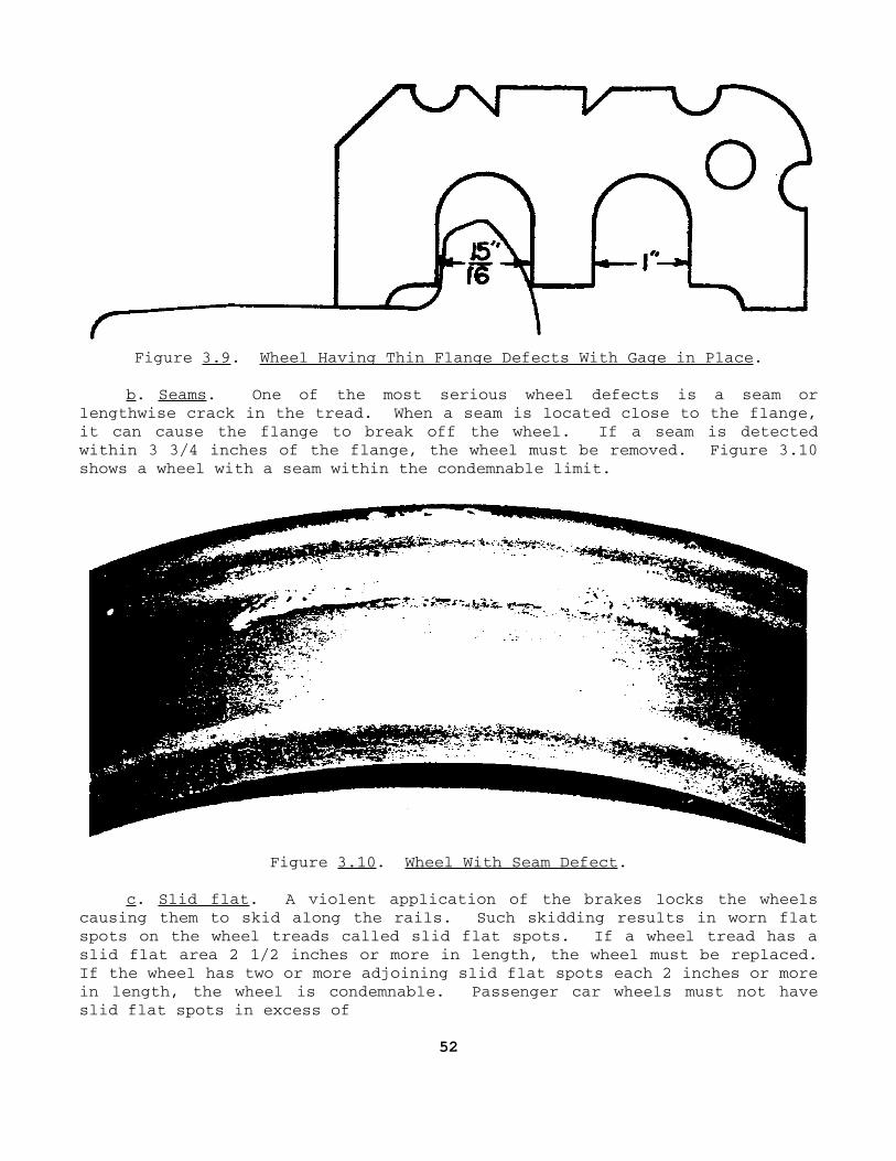
Figure 3.9. Wheel Having Thin Flange Defects With Gage in Place.
b. Seams. One of the most serious wheel defects is a seam orlengthwise crack in the tread. When a seam is located close to the flange,it can cause the flange to break off the wheel. If a seam is detectedwithin 3 3/4 inches of the flange, the wheel must be removed. Figure 3.10shows a wheel with a seam within the condemnable limit.
Figure 3.10. Wheel With Seam Defect.
c. Slid flat. A violent application of the brakes locks the wheelscausing them to skid along the rails. Such skidding results in worn flatspots on the wheel treads called slid flat spots. If a wheel tread has aslid flat area 2 1/2 inches or more in length, the wheel must be replaced.If the wheel has two or more adjoining slid flat spots each 2 inches or morein length, the wheel is condemnable. Passenger car wheels must not haveslid flat spots in excess of
52

1 inch. Figure 3.11 shows a single slid flat defect measuring more than 21/2 inches; figure 3.12 shows two adjoining slid flat spots each exceedingthe 2inch limit.
Figure 3.11. Single Slid FlatWheel Defect.
Figure 3.12. Adjoining Slid FlatDefects.
d. Broken rim. Sometimesinspectors condemn wheels andremove them from service when theydetect chipped places on theoutside edge of the rim; however, asmall amount of chipping does notimpair their serviceability. Thewheel should not be condemned untilthe rim is broken off a distance of3 3/4 inches from the flange whenthe break slopes inwardly. Figure3.13 illustrates the methods ofgaging broken rims; the two wheelsshown have reached the condemnablelimit.
e. Cracked plate. Any wheelwith a cracked plate should beremoved from service. Such a crackalmost always originates in eitherthe hub or the rim. A 2to
Figure 3.13. Wheels With BrokenRim Defects.
53

3inch crack in the plate can grow into a socalled "cupid's bow" crack, aspart A of figure 3.14 shows. Its name is derived from the bowlike shape thecrack assumes when the two ends turn outward toward the rim. A crackedplate is easily detected by a careful inspection of the wheels. However, ifsuch a crack is neglected, it can extend through the rim, as part B offigure 3.14 shows, and cause the wheel to fail.
Figure 3.14. Cracked Plates.
f. Tread worn hollow. A gage is provided for condemning wheels forworn hollow treads, as shown in figure 3.15. When the two ends of the gagetouch the rim and the flange but the bottom nipple on the gage does nottouch the tread, the wheel has reached the condemnable limit and must beremoved from service. The real limit of a tread worn hollow defect is theheight of the flange and this is what the gage is based on. Wheels shouldnot be condemned for having treads worn hollow before the gage limit isactually reached.
g. Out of round. If a wheel has a worn spot in the tread more than3/64inch deep, it is out of round and has reached the condemnable limit. Awheel with this defect causes damage to the track, equipment, and ladingwhen the train is traveling at high speeds. Figure 3.16 shows the gageapplied to a defective 33inch wheel.
54


Figure 3.15. Wheel Having Tread Worn Hollow Defect With Gage inPlace.
Figure 3.16. Wheel Out of Round With Gage in Place.
3.13. SAFETY APPLIANCES
The steps, running boards, and handholds of all railway equipment aresafety appliances. Lives and limbs of railway workmen are greatlyendangered if these items are broken, loose, or bent. Safety appliancesshould be inspected frequently and any defects reported and repairedimmediately. Figure 3.17 shows a typical railway car and its safetyappliances.
3.14. SUMMARY
Preventive maintenance is essential to the operational readiness ofrailway cars because it can reduce greatly the possibilities of expensiveand timeconsuming heavy repairs. All car components should have frequentpreventive maintenance checks, particularly the truck assemblies since theymust support the car and be able to ride the rails and negotiate curvesproperly. Safety appliances on cars should be inspected often and anydefective ones repaired immediately to avoid endangering the lives ofrailway workmen.
55


Figure 3.17. Railway Car Safety Appliances.
Section III. Inspection and Maintenance
3.15. GENERAL
When railway cars are inspected and defects are noted, the properforms must be used to point out the defects to the repairmen at the carrepair track, to record the maintenance performed, and to insure that thecars are not placed in service until the defects are corrected. Thissection discusses the forms used in the inspection and maintenance ofrailway cars; however, it gives only general information on the entries tobe made on them. Anyone responsible for completing the forms must haveTechnical Manual 55203, Maintenance of Railway Cars, that describes theirentries. Before the discussion of the forms begins, paragraph 3.16 explainsthe kinds of inspections made.
3.16. INSPECTION OF RAILWAY CARS
Inspection of railway cars differs from that of locomotives in thatrailway cars have only one periodic or scheduled inspectionthe
56


annual. However, they are inspected with a frequency consistent with theiruse. The more a car is used the more it is inspected and, of course, themore maintenance it needs. Other than the annual inspection, railway carsare normally inspected at loading points and at receiving and departureyards upon arrival and departure.
a. At loading points. Although shippers are responsible for loadingrail cars properly, transportation railway service inspectors areresponsible for checking them at loading points before accepting the carsfor movement. They inspect each car to insure that it has been properlyloaded and secured so that the load cannot shift while in transit. Thelading should be so positioned that its weight is properly distributed onthe car. The inspectors check the car for any damage that may have occurredwhile it was being loaded; they also check it for proper lubrication.Railway cars should not leave loading points until this inspection has beenmade.
b. On arrival. When railway cars arrive at a receiving yard, they arethoroughly inspected. They are visually inspected for defects andlubrication points are checked. Such light repairs as repacking a journalbox or replacing a broken cotter key or a worn brakeshoe are made while thecars are in the receiving yard. The brake system is also tested during thearrival inspection. The brakes are applied to resist the pull of thelocomotive so that the slack is taken up as the train stops. The draftgears are stretched out as a result of this action, and inspectors begin ateach end of the train checking couplers, draft gears, side frames, wheels,underframes, and airbrake piston travel. The journal box lids are openedand the packing and lubrication checked. Inspectors place a Bad Order Card(DA Form 55164) on cars having defects that cannot be readily repaired inthe receiving yard. The badorder cars are moved to the repair, or riptrack, where they are repaired as soon as possible. ("Rip" stands forrepair, inspect, paint.) When the arrival inspection is finished, the carsare moved to the classification yard where they are classified or sortedaccording to destination or to content.
c. On departure. After railway cars have been classified, they aremoved to the departure yard and made up into trains. Inspectors againtravel the length of the train making a test of the train's airbrake system.At the same time, they make another general inspection and insure that thejournal box lids are closed.
d. Annual inspection. Once each year, a car is inspected, and the dateof the inspection is stenciled on the car. When a car arrives at a railwayyard and the inspectors note that the annual inspection is due, they notifythe yardmaster who has the car moved
57

to the car repair track if the car is empty. If loaded, it continues to itsdestination; but when next entering a yard empty, the car is moved to thecar repair track to undergo the annual inspection.
3.17. FIELD INSPECTION DATA FOR RAIL CARS
Field Inspection Data, USA, USAX, USNX, DODX, Rail Cars, DD Form 1335,is used as a checklist when inspecting both freight and passenger rail cars.The checklist must be supported by a narrative recorded on DA Form 2407.The DD Form 1335, shown in figure 3.18, lists the items to be checked inperforming the inspection. All of the required Information to be listed inthe heading of the form for a specific rail car is stenciled on the side ofthe car. This includes the capacity, weight, dates of inspections, anddates of last tank and valve tests. The body of the form lists the items tobe checked, a condition column, and a remarks column which gives anabbreviated description of the defect. The form is retained by thedesignated DS/GS rail support unit until the required repairs have beencompleted and then the forms are destroyed. In the absence of a DS/GS unit,the forms are forwarded to USATSC, ATTN: AMSTSM.
3.18. AIR BRAKE DEFECT TAG
The Air Brake Defect Tag, DA Form 55161, as shown in figure 3.19, isused by a car inspector or train conductor to tag a car having inoperativebrakes. The form, made of red cardboard with black lettering, is attachedto the brake pipe of the car having defective brakes so that the defect isnoticed readily. The car is sent to the car repair track for repair beforeit can depart from the terminal. In CONUS, inspectors or other maintenancemen, after completing repairs, make a "repairs made" notation on the tag andthen forward it to the officer in charge at the installation. In a theaterof operations, after a similar notation is made, the tag is forwarded to theofficer in charge of air brake repairs in the transportation railwaybattalion.
3.19. INSPECTOR'S RECORD
The Inspector's Record, DA Form 55162, is used by car inspectors toreport all defects on cars they inspect. Defective cars include thosehaving defective handbrakes, those already carded for repair tracks, thosecarded for reweighing, and those found defective for any other reason. In atheater of operations, the completed report is sent to the officer in chargeof car repairs in the transportation railway battalion. In CONUS, the formis forwarded to the
58

Figure 3.18. Field Inspection Data, USA, USAX, USNX, DODX, RailCars, DD Form 1335.
59

Figure 3.19. Air Brake Defect Tag, DA Form 55161.
installation transportation officer at the installation where the inspectionis made. On the sample 55162 shown in figure 3.20, note that the inspectorfound no defects and marked "O. K." under condition.
3.20. CAR INSPECTOR'S TRAIN REPORT
The chief car inspector uses the Car Inspector's Train Report, DA Form55163, to report the inspection of each train arriving at or departing fromterminals or originating points where car inspectors are located. In atheater of operations, the form is filed by the officer in charge of carrepairs in the transportation railway battalion; in CONUS, it is filed atthe installation. On the sample form shown in figure 3.21, note thatentries are divided into two groups: those for the train coming in andthose for it going out.
3.21. BAD ORDER CARD
A Bad Order Card, DA Form 55164, is used by car inspectors in yardsor other places where cars are checked to indicate that they are not safefor service. When an inspector finds a car needing repairs that requiremoving it to a repair track, he writes the necessary information on two 55164's, one of which is shown in figure 3.22. Notice on the sample that thisincludes the date, defect, car
60

Figure 3.20. Inspector's Record, DA Form 55162.
Figure 3.21. Car Inspector's Train Report, DA Form 55163.
61

initials and number, whether the car is loaded or empty, place where car isinspected and tagged, and the inspector's name. The inspector then places acard on each side of the defective car. On a car having wooden sides, thecards are attached just below the car number; if the car has steel sides,the cards are placed on boards provided for the purpose.
Figure 3.22. Bad Order Card, DA Form 55164.
If the side of the card used has the large words "Bad Order" appearingon a black background, this signifies that a loaded car may be moved to adestination within the local switching district for unloading before repairshave to be made. It may also signify that a badorder empty car can bemoved from one shop or repair point to another for repairs. However, if theside of the card used has the large words "Bad Order" on a red background,the car can be moved only to the repair track and repairs must be madebefore the car is used again. Most terminals have both light and heavyrepair tracks. By crossing out one or the other of the words light or heavyon the card, the inspector shows which repair track the car should be movedto.
Bad order cards are not removed from a car until repairs have beencompleted, and then only by those authorized to remove them. In both CONUSand theaters of operations, the inspector responsible for the repairsremoves and destroys the cards when he declares the car ready for furtherservice.
3.22. SUMMARY
The only periodic inspection of railway cars is made annually.However, they are also inspected at loading points and upon arrival
62

and departure at receiving and departure yards. At loading points, they arechecked for proper loading, possible damage, and proper lubrication. At areceiving yard, a thorough inspection is made for defects, lubricationpoints are checked, and the brake system is tested. At the departure yard,the airbrake system is again tested and journal box lids are checked to besure they are closed. Following an annual inspection, the date of theinspection is stenciled on the car. Among the forms the inspectors use inrailway car inspection and maintenance are the Inspection Report for RailwayCars, the Airbrake Defect Tag, the Inspector's Record, the Car Inspector'sTrain Report, and the Bad Order Card.
63

CORRESPONDENCE COURSE OF THEU.S. ARMY TRANSPORTATION SCHOOL
SOLUTIONS
TRANS SUBCOURSE 675...................Maintenance of DieselElectricLocomotives and Rolling Stock.
(All references are to Reference Text 675.)
LESSON 1
Weight Exercise Weight Exercise
3 1. T. (par. 2.4a) 3 12. D. (par. 2.10b)
3 2. T. (par. .2.4) 3 13. A. (par. 2.13)
3 3. F. (par. 2.4) 3 14. B. (par. 2.12b)
3 4. T. (par. 2.12a) 3 15. C. (par. 2.14)
3 5. T. (par. 2.4a) 3 16. D. (par. 2.17)
4 6. F. (par. 2.3a) 3 17. A. (par. 2.15)
4 7. T. (par. 1.2a) 3 18. B. (par. 2.16)
4 8. F. (par. 2.4) 3 19. C. (par. 2.14)
4 9. T. (par. 2.3) 3 20. C. (par. 2.24)
4 10. F. (par. 2.3b) 3 21. A. (par. 2.21)
3 11. C. (par. 2.11b) 3 22. D. (par. 2.20)
LESSON 2
3 1. T. (par. 3.11d) 4 5. T. (par. 3.2)
3 2. F. (par. 3.5b) 4 6. T. (par. 3.4c)
4 3. T. (par. 3.2) 4 7. F. (par. 3.10c)
4 4. T. (par. 3.3c) 4 8. E. (par. 3.12b)
1 JUNE 1976

Weight Exercise Weight Exercise
4 9. D. (par. 3.12f) 3 20. B. (par. 3.10a)
4 10. A. (par. 3.12g) 3 21. D. (par. 3.19)
4 11. B. (par. 3.12c) 3 22. E. (par. 3.20)
4 12. C. (par. 3.12e) 3 23. A. (par. 3.21)
3 13. E. (par. 3.4) 3 24. C. (par. 3.18)
3 14. A. (par. 3.3b) 3 25. B. (par. 3.17)
3 15. C. (par. 3.3a) 3 26. A. (par. 3.21)
3 16. D. (par. 3.4e(1)) 3 27. B. (par. 3.6)
3 17. E. (par. 3.4e(4)) 3 28. C. (par. 3.16b)
3 18. D. (par. 3.4a) 3 29. A. (par. 3.4e(4))
3 19. C. (par. 3.4a) 3 30. C. (par. 3.13)
2