Embed Size (px)
Citation preview
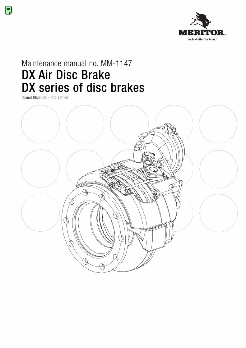
Maintenance manual no. MM-1147
DX Air Disc BrakeDX series of disc brakesIssued 06/2003 - 2nd Edition
an ArvinMeritor brand
2 ArvinMeritor DX Air Disc Brake
Service Notes
Before You BeginThis publication provides installation and maintenance proceduresfor the DX Air Disc Brake.
The information contained in this publication was current at thetime of printing and is subject to revision without notice or liability.
You must understand all procedures and instructions before youbegin maintenance and service procedures.
You must follow your company's maintenance and service guidelines.
You must use special tools, when required, to avoid seriouspersonal injury and damage to components.
Meritor uses the following notations to alert the user of possiblesafety issues and to provide information that will help to preventdamage to equipment and components.
WARNINGA WARNING indicates a procedure that you must followexactly to avoid serious personal injury.
CAUTIONA CAUTION indicates a procedure that you must followexactly to avoid damaging equipment or components.Serious personal injury can also occur.
NOTE: A note indicates an operational, procedure or instructionthat is important for proper service. A NOTE can also supplyinformation that will help to make service quicker and easier.
This symbol indicates that you must tighten fasteners to a specific torque.
Information contained in this publication was in effect at the time the publicationwas approved for printing and is subject to change without notice or liability.ArvinMeritor Commercial Vehicle Systems reserves the right to revise theinformation presented to discontinue the production of parts described at any time.
Access Information on ArvinMeritor's WebSiteAdditional maintenance and service information for ArvinMeritor'scommercial vehicle systems component lineup is also available atwww.arvinmeritor.com.
To access information, click on Products & Services/Tech LibraryIcon/HVS Publications. The screen will display an index ofpublications by type.
3ArvinMeritor DX Air Disc Brake
Contents
05 Section 1: Description06 General description06 Brake pad wear indicator
07 Section 2: Introduction08 Exploded view - Pre March 2001 production10 Exploded view - Post March 2001 production12 Operating principles13 Automatic self-adjuster mechanism14 Automatic clearance compensation15 Thrust plate
17 Section 3: Maintenance 18 Maintenance operations19 Maintenance intervals20 A - Pad Replacement21 B - Manual Adjustment21 C - Rotor Inspection24 D - Automatic Adjuster Operating Tests25 E - Checking Slide Pin Bush Wear25 F - Brake Slide Pin Checks on vehicle
Brake Servicing on bench26 G - Disassembly of Actuating System28 H - Slide Pin & Bushing Replacement31 I - Actuating Piston Seal Boot Replacement32 J - Saddle Replacement34 K - Eccentric Shaft & Cover Plate Replacement36 L - Stabiliser Bar Replacement38 M -Lever Replacement38 N - Thrust Plate Centering in Saddle39 O - Re-assembly of brake unit on vehicle and pad refitting
41 Section 4: Torque chart42 Torque Chart, Special tools, Sealants
43 Section 5: Troubleshooting44 Troubleshooting
47 Section 6: Service tools
pg.
Terms used in this manual
Manufacturer:ARVINMERITOR CVS
Manual:Maintenance manual no. MM-1147
Device:Air disc brake, DX series
Technician:Qualified personnel working on brake maintenance and servicing.
Maintenance and servicing:Maintenance and servicing refer to periodical checks and/orreplacement of device parts or components. It also refers to thedetermining of the cause of a malfunction in order to restore theinitial operating conditions.
Operator:Any person who will use the device as part of a more complexdevice.
WarrantyWarranty applies to the air disc brake installed on vehicles forwhich it was designed. Warranty is void in the following cases:
• Improper use of the vehicle on which the air disc brake is installed (usage conditions, overloading etc.)
• Tampering with vehicle components that may affect brake performance.
• Use of non-original spare parts.
• Improper installation, adjustment, repair or modification.
• Poor or improper maintenance (including consumables other than those specified).
Further information on warranty conditions may be obtaineddirectly from the manufacturer or by referring to the ArvinMeritorweb site www.arvinmeritor.com
4 ArvinMeritor DX Air Disc Brake
5ArvinMeritor DX Air Disc Brake
pg.
1
Description
06 General description06 Brake pad wear warning indicator (PWWI)
6 ArvinMeritor DX Air Disc Brake
General descriptionThe ArvinMeritor CVS DX series of air disc brakes is a family ofhigh performance, low weight, high efficiency brakes designed fortrucks, coaches, buses and other commercial vehicles requiringbetween 10,000 and 23,000 Nm of braking torque at eachwheel.
Clamping force is produced by a globular cast iron caliper locatedabove the rotor and housing two lining pads. The pads are pushedagainst the rotor by a dual piston actuating block connected to aneccentric shaft, which is in turn driven by a lever operated by astandard air actuator (air chamber).
The caliper is carried on a saddle which is a fixed support boltedto the axle flange. Equalised clamping action both on the innerand outer pads is generated by allowing the caliper to float on thetwo slide pins fixed to the saddle.
Clamping force generated by the primary actuation is applied tothe inner pad, which forces it into contact with the rotor. Reactiveforce through the caliper body applies equal clamping force to theouter pad applying a balanced clamping force to the rotor.
The slide pins also allow the caliper to freely position itself on thesaddle to compensate for the reduction in lining pad thicknessdue to wear.
An automatic self-adjuster mechanism is incorporated in order tomaintain constant clearance between pads and rotor. Theautomatic adjuster operates on each clamping action to senseexcessive pad-rotor clearance, and reduces excessive clearanceby a fixed proportion with each actuation.
For brake adjustment and new lining installation, the brakeincorporates provision for manual adjustment, easily performed byusing a standard hexagonal wrench.
Brake actuation can be either clockwise or counter clockwise,depending on how the air actuator has been installed on brakeunit.
Regardless of which side the brake unit is installed onvehicle, the brake is referred to as:RIGHT when actuation is clockwise - Fig. 2-2 a) and b)LEFT when actuation is counter clockwise - Fig. 2-2 c) and d)
Clockwise actuation - Fig. 2-2 a) and b) - will always requireleft-hand threaded adjuster sleeves and pistons (actuationpistons marked on the bottom with the letter L) and itsrelated right housing (R.H.). The opposite applies for brakes with counter clockwiseactuation - Fig. 2-2 c) and d).
Brake pad wear warning indicatorBrakes can have different types of pad wear warning indicators(PWWI) according to vehicle manufacturer’s requirements. Followvehicle manufacturer’s instructions for proper installation andconnecting procedures.
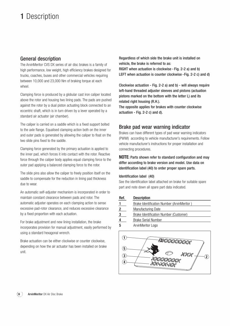
NOTE: Parts shown refer to standard configuration and maydiffer according to brake version and model. Use data onidentification label (40) to order proper spare parts.
Identification label (40)See the identification label attached on brake for suitable sparepart and note down all spare part data indicated.
1 Description
12345
Ref. Description
Brake Identification Number (ArvinMeritor )Manufacturing DateBrake Identification Number (Customer)Brake Serial NumberArvinMeritor Logo
7ArvinMeritor DX Air Disc Brake
pg.
2
Introduction
08 Exploded view - Pre March 2001 production09 Parts list10 Exploded view - Post March 2001 production11 Parts list12 Operating principles13 Automatic self-adjuster mechanism14 Automatic clearance compensation15 Thrust plate
8 ArvinMeritor DX Air Disc Brake
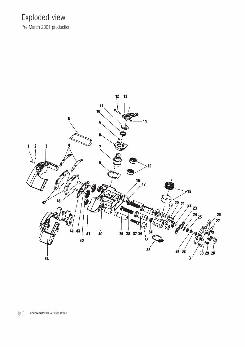
Exploded view Pre March 2001 production
9ArvinMeritor DX Air Disc Brake
1234567891011121314151617181920212223
Ref Description Q.ty
Stabiliser bar retaining pin 1Pin clip 1Caliper 1Anti-rattle spring 2Stabiliser bar 1Cover plate gasket 1Eccentric shaft 1Cover plate 1Cover plate screws 2Eccentric shaft seal 1Eccentric shaft seal boot 1Clamp bolt (lever) 1Lever 1Clamp bolt nut (lever) 1Eccentric shaft bearing unit 2End plate gasket 1Slide pin bushing 2Eccentric shaft support bearing 1Actuation block 1Damping spring 2Snap ring 2Bevel gear / torque limiter 1Adjustment box ** (preinstalled unidirectional bearing) 1
24252627282930313233343536373839404142434445464748
Ref Description Q.ty
Damping ring 2Compression spring 1Air actuator end plate and bracket 1Flathead screw (end plate screw) 2End plate cap 1Plug (of adjuster port) 1Copper washer 1Hexagonal head screw (end plate screw) 4Adjuster device screw 1Adjuster gear segment 1Adjuster sleeve gear * 2Slide pin protective cap 2Adjuster sleeve ** 2Slide pin locking screw 2Actuating piston ** 2Slide pin 2Identification label 1Slide pin seal boot 2Actuating piston seal boot 2Roll pin 2Thrust plate 1Saddle 1Actuating piston screw 2Brake pads 2Brake pad wear indicator (if fitted) 1
Parts list Pre March 2001 production
* Gear is shown separately since it is an integral part withadjuster screw.
** These components are different according to actuationdirection (clockwise or counter – clockwise) (Fig. 2-2).
10 ArvinMeritor DX Air Disc Brake
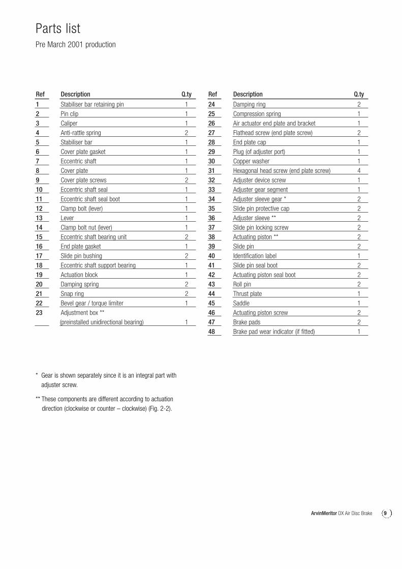
Exploded view Post March 2001 production
11ArvinMeritor DX Air Disc Brake
12345678912131517181920212223
242526
27
RefRef Description Q.ty
Stabiliser bar retaining pin 1Pin clip 1Caliper 1Anti-rattle spring 2Stabiliser bar 1Cover plate gasket 1Eccentric shaft 1Cover plate housing 1Cover plate screws 2Clamp bolt (lever) 1Lever 1Eccentric shaft bearing unit 2Slide pin bushing 2Eccentric shaft support bearing 1Actuation block 1Damping spring 2Snap ring 2Bevel gear / torque limiter 1Adjustment box ** 1(preinstalled unidirectional bearing)Damping ring 2Compression spring 1Air actuator end plate and bracket 1(shape may vary due to brake part number)End plate screws 6(style may vary due to brake part number)
2829303233343536373839a39b404142434445464748495051
Ref Description Q.ty
End plate cap 1Plug (of adjuster port) 1Copper washer 1Adjuster device screw 1Adjuster gear segment 1Adjuster sleeve gear * 2Slide pin protective cap 2Adjuster sleeve ** 2Slide pin locking screw (long) 1Actuating piston ** 2Slide pin (to suit long locking screw) 1Slide pin (to suit short locking screw) 1Identification label 1Slide pin seal boot 2Actuating piston seal boot 2Roll pin 2Thrust plate 1Saddle 1Actuating piston screw 2Brake pads 2Brake pad wear indicator (if fitted) 1Cover plate eccentric shaft seal 1Eccentric shaft seal 1Slide pin locking screw (short) 1
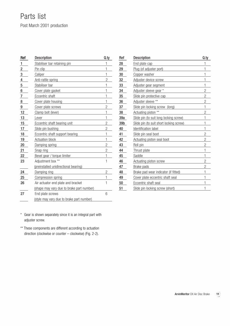
Parts list Post March 2001 production
* Gear is shown separately since it is an integral part with adjuster screw.
** These components are different according to actuation direction (clockwise or counter – clockwise) (Fig. 2-2).
12 ArvinMeritor DX Air Disc Brake
2 Introduction
Operating principles
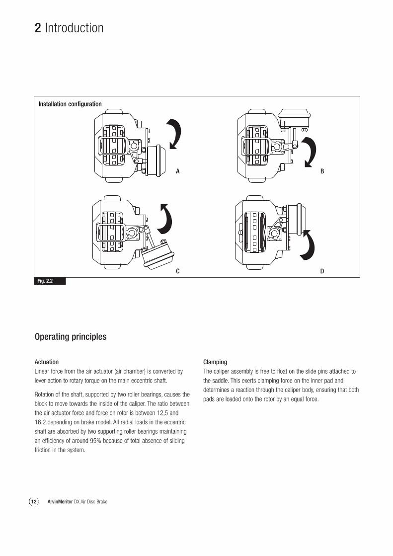
ActuationLinear force from the air actuator (air chamber) is converted bylever action to rotary torque on the main eccentric shaft.
Rotation of the shaft, supported by two roller bearings, causes theblock to move towards the inside of the caliper. The ratio betweenthe air actuator force and force on rotor is between 12,5 and16,2 depending on brake model. All radial loads in the eccentricshaft are absorbed by two supporting roller bearings maintainingan efficiency of around 95% because of total absence of slidingfriction in the system.
ClampingThe caliper assembly is free to float on the slide pins attached tothe saddle. This exerts clamping force on the inner pad anddetermines a reaction through the caliper body, ensuring that bothpads are loaded onto the rotor by an equal force.
Fig. 2.2
A B
C D
Installation configuration
13ArvinMeritor DX Air Disc Brake
2 Introduction
Fig. 2.3
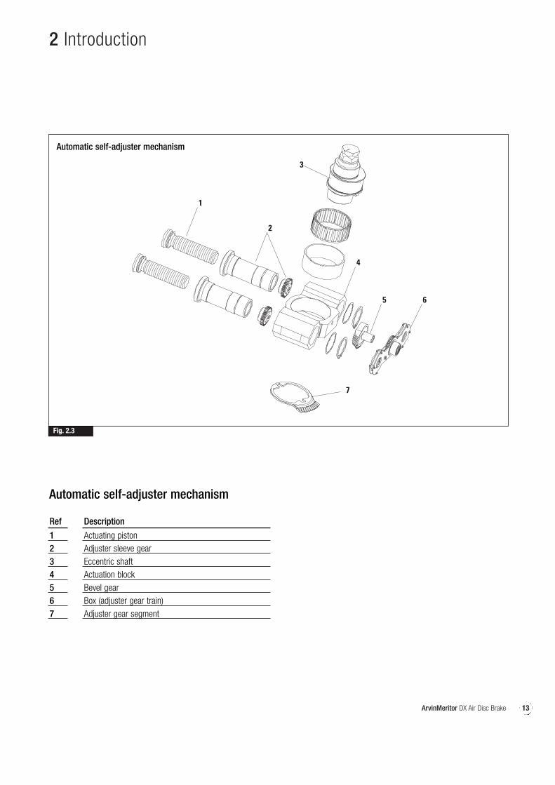
Automatic self-adjuster mechanism
1234567
Ref Description
Actuating pistonAdjuster sleeve gearEccentric shaftActuation blockBevel gearBox (adjuster gear train)Adjuster gear segment
Automatic self-adjuster mechanism
14 ArvinMeritor DX Air Disc Brake
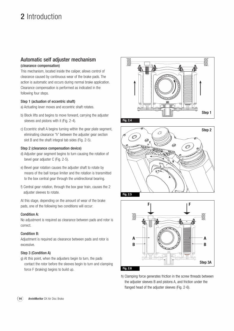
Automatic self adjuster mechanism(clearance compensation)This mechanism, located inside the caliper, allows control ofclearance caused by continuous wear of the brake pads. Theaction is automatic and occurs during normal brake application.Clearance compensation is performed as indicated in thefollowing four steps.
Step 1 (actuation of eccentric shaft)a) Actuating lever moves and eccentric shaft rotates.
b) Block lifts and begins to move forward, carrying the adjustersleeves and pistons with it (Fig. 2-4).
c) Eccentric shaft A begins turning within the gear plate segment,eliminating clearance “h” between the adjuster gear sectionslot B and the shaft integral tab sides (Fig. 2-5).
Step 2 (clearance compensation device)d) Adjuster gear segment begins to turn causing the rotation of
bevel gear adjuster C (Fig. 2-5).
e) Bevel gear rotation causes the adjuster shaft to rotate bymeans of the ball torque limiter and the rotation is transmittedto the box central gear through the unidirectional bearing.
f) Central gear rotation, through the box gear train, causes the 2adjuster sleeves to rotate.
At this stage, depending on the amount of wear of the brakepads, one of the following two conditions will occur:
Condition A:No adjustment is required as clearance between pads and rotor iscorrect.
Condition B:Adjustment is required as clearance between pads and rotor isexcessive.
Step 3 (Condition A)g) At this point, when the adjusters begin to turn, the pads
contact the rotor before the sleeves begin to turn and clampingforce F (braking) begins to build up.
2 Introduction
Fig. 2.4
Step 1
Fig. 2.5
A
h
B
C
Step 2
Fig. 2.6
Step 3A
h) Clamping force generates friction in the screw threads betweenthe adjuster sleeves B and pistons A, and friction under theflanged head of the adjuster sleeves (Fig. 2-6).
15ArvinMeritor DX Air Disc Brake
2 Introduction
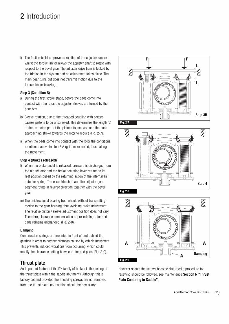
Fig. 2.7
Step 3B
Fig. 2.8
Step 4
Fig. 2.9
A A
A Damping
i) The friction build-up prevents rotation of the adjuster sleeveswhilst the torque limiter allows the adjuster shaft to rotate withrespect to the bevel gear. The adjuster drive train is locked bythe friction in the system and no adjustment takes place. Themain gear turns but does not transmit motion due to thetorque limiter blocking.
Step 3 (Condition B)j) During the first stroke stage, before the pads come into
contact with the rotor, the adjuster sleeves are turned by thegear box.
k) Sleeve rotation, due to the threaded coupling with pistons,causes pistons to be unscrewed. This determines the length ‘L’of the extracted part of the pistons to increase and the padsapproaching stroke towards the rotor to reduce (Fig. 2-7).
i) When the pads come into contact with the rotor the conditionsmentioned above in step 3 A (g-i) are repeated, thus haltingthe movement.
Step 4 (Brakes released)l) When the brake pedal is released, pressure is discharged from
the air actuator and the brake actuating lever returns to itsrest position pulled by the returning action of the internal airactuator spring. The eccentric shaft and the adjuster gearsegment rotate in reverse direction together with the bevelgear.
m) The unidirectional bearing free-wheels without transmittingmotion to the gear housing, thus avoiding brake adjustment.The relative piston / sleeve adjustment position does not vary.Therefore, clearance compensation of pre-existing rotor andpads remains unchanged. (Fig. 2-8).
DampingCompression springs are mounted in front of and behind thegearbox in order to dampen vibration caused by vehicle movement.This prevents induced vibrations from occurring, which couldmodify the clearance setting between rotor and pads (Fig. 2-9).
Thrust plateAn important feature of the DX family of brakes is the setting ofthe thrust plate within the saddle abutments. Although this isfactory set and provided the 2 locking screws are not removedfrom the thrust plate, no resetting should be necessary.
However should the screws become disturbed a procedure forresetting should be followed: see maintenance Section N “ThrustPlate Centering in Saddle”.

16 ArvinMeritor DX Air Disc Brake
17ArvinMeritor DX Air Disc Brake
pg.
3
Maintenance
18 Maintenance operations19 Maintenance intervals20 A - Pad Replacement21 B - Manual Adjustment21 C - Rotor Inspection24 D - Automatic Adjuster Operating Tests25 E - Checking Slide Pin Bush Wear25 F - Brake Slide Pin Checks on vehicle
Brake Servicing on bench26 G - Disassembly of Actuating System28 H - Slide Pin & Bushing Replacement31 I - Actuating Piston Seal Boot Replacement32 J - Saddle Replacement34 K - Eccentric Shaft & Cover Plate Replacement36 L - Stabiliser Bar Replacement38 M - Lever Replacement38 N - Thrust Plate Centering in Saddle39 O - Re-assembly of brake unit on vehicle and
pad refitting
18 ArvinMeritor DX Air Disc Brake
3 Maintenance
Maintenance operationsIn order to ensure reliable and efficient brake operation,recommended maintenance intervals, lubricants and correctprocedures should be followed carefully.
Spare partsWarranties shall be null if non-original ArvinMeritor spare partsare used.
Technical specificationsBelow are the technical specifications of the DX series of discbrakes.
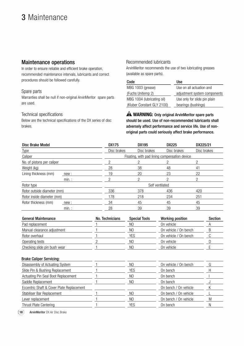
Disc Brake Model DX175 DX195 DX225 DX225/21Type Disc brakes Disc brakes Disc brakes Disc brakesCaliper Floating, with pad lining compensation deviceNo. of pistons per caliper 2 2 2 2Weight (kg) 28 38 48 41Lining thickness (mm) new : 19 20 23 22
min. : 2 2 2 2Rotor type Self ventilatedRotor outside diameter (mm) 336 378 436 420Rotor inside diameter (mm) 178 218 234 251Rotor thickness (mm) new : 34 45 45 45
min. : 28 39 39 39
Recommended lubricantsArvinMeritor recommends the use of two lubricating greases(available as spare parts).
General Maintenance No. Technicians Special Tools Working position SectionPad replacement 1 NO On vehicle AManual clearance adjustment 1 NO On vehicle / On bench BRotor overhaul 1 YES On vehicle / On bench COperating tests 2 NO On vehicle DChecking slide pin bush wear 1 NO On vehicle E
Brake Caliper Servicing:Disassembly of Actuating System 1 NO On vehicle / On bench GSlide Pin & Bushing Replacement 1 YES On bench HActuating Pin Seal Boot Replacement 1 NO On bench ISaddle Replacement 1 NO On bench JEccentric Shaft & Cover Plate Replacement On bench / On vehicle KStabiliser Bar Replacement 1 NO On bench / On vehicle LLever replacement 1 NO On bench / On vehicle MThrust Plate Centering 1 YES On bench N
Code UseMBG 1003 (grease) Use on all actuation and (Fuchs Unitemp 2) adjustment system componentsMBG 1004 (lubricating oil) Use only for slide pin plain (Kluber Constant GLY 2100) bearings (bushings)
WARNING: Only original ArvinMeritor spare partsshould be used. Use of non-recommended lubricants shalladversely affect performance and service life. Use of non-original parts could seriously affect brake performance.
19ArvinMeritor DX Air Disc Brake
3 Maintenance
Maintenance IntervalsAlthough there is no routine maintenance of the brake assemblyrequired, it is important the following inspections are carried outat the periods specified, or those detailed in the vehicle or trailermanufacturer’s manual.
Service intervalsEvery 3 months or 20000 km.A visual inspection of pad life should be made. Brake pads shouldbe replaced when the lining thickness has worn to 2.0 mm.
Visually inspect the general condition of the brake assembly fordamage or corrosion.
Inspect the slide pin and actuating piston seal boots and ensurethey are undamaged and securely located. If any of the boots aredetached or damaged the relevant part of the brake should bedismantled and the components examined for corrosion anddamage.
If there is any doubt in the suitability for further service,replace/rectify in accordance with the instructions of this manualor the vehicle/trailer manufacturer’s instructions.
Every 12 months or at the vehicle / trailer manufacturer’srecommendations.Remove brake pads as described in the pad replacement section.
Inspect the slide pin and actuating piston seal boots and ensurethey are undamaged and securely located. If any of the boots aredetached or damaged the relevant part of the brake should bedismantled and the components examined for corrosion anddamage.
Replace/rectify in accordance with the vehicle /trailermanufacturer’s instructions.
Check the housing assembly slides easily on the slide pinssecured to the saddle. If the housing does not slide easily, removefrom the saddle as described in Section J “Slide Pin & BushingReplacement”.
If there is any doubt in the suitability for further service, replacewith new components.
Check the slide pin bush for wear in line with instructions inSection E “Checking Slide Pin Bush Wear”.
WARNING Take care not to trap fingers whilst checking the slidingaction of the brake.
Check the brake disc for signs of heavy grooving; crackingor corrosion and the thickness dimension are in accordancewith recommendation of the manual of the vehicle/trailermanufacturer’s recommendations.
NOTE: These service intervals are meant as a guide, thefrequency should be tailored to suit the environmental conditionsof the brake assembly and hence to the vehicle/trailer operatingconditions, so therefore it is up to the operator to determine themost appropriate service intervals with technical support fromArvinMeritor if necessary.
These service intervals are the maximum recommended timesunder normal operating conditions. Extreme temperatures oradverse conditions (e.g. dusty or severe environments, frequentuphill driving, very low temperatures) will require more frequentservicing. It is the responsibility of the vehicle operator toschedule these intervals, with technical support from ArvinMeritorif necessary.
In some cases, it is possible to carry out operations with brakeunit mounted on vehicle. However, ARVINMERITOR recommendsthat all operations (with the exception of pad replacement andoperating tests) be carried out with the brake unit removed fromvehicle and installed on bench. This promotes safer workingconditions and better results.
20 ArvinMeritor DX Air Disc Brake
3 Maintenance
(A) Pad replacementBrake pad replacement is necessary when the friction lining isworn down to a thickness of 2 mm (total thickness inclusive ofsupport plate, is 9 mm).
With the vehicle on a hard level surface, fit anti-roll chocksunder the road wheels to prevent it from moving eitherforward or backwards.
WARNINGCarefully follow the manufacturer's instructions whenjacking the vehicle and removing the road wheel.
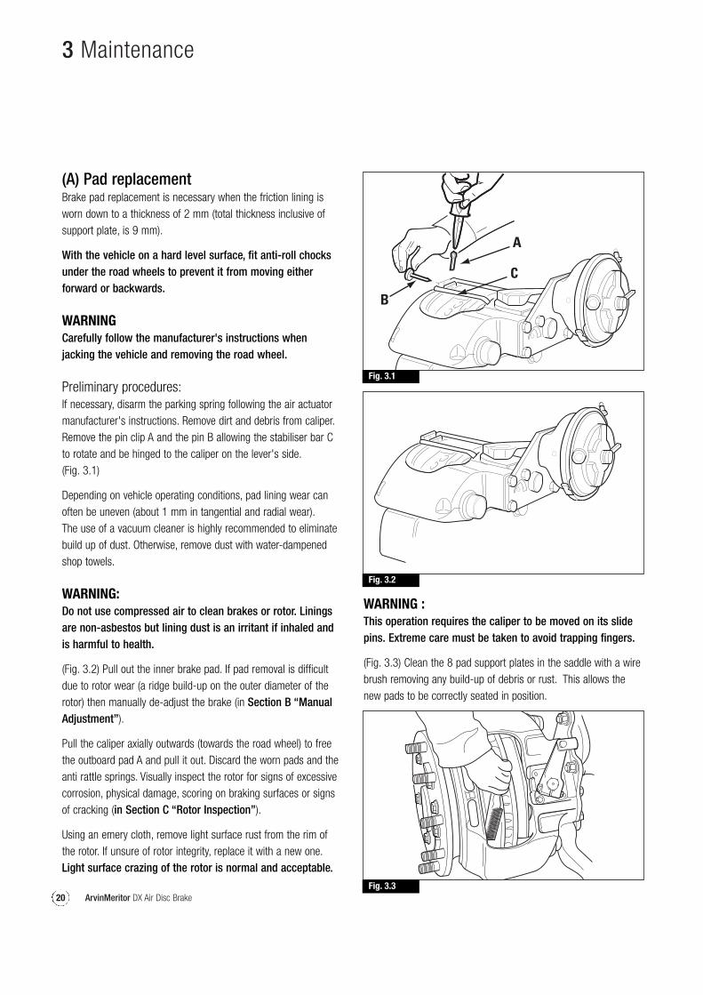
Preliminary procedures:If necessary, disarm the parking spring following the air actuatormanufacturer's instructions. Remove dirt and debris from caliper.Remove the pin clip A and the pin B allowing the stabiliser bar Cto rotate and be hinged to the caliper on the lever's side.(Fig. 3.1)
Depending on vehicle operating conditions, pad lining wear canoften be uneven (about 1 mm in tangential and radial wear).The use of a vacuum cleaner is highly recommended to eliminatebuild up of dust. Otherwise, remove dust with water-dampenedshop towels.
WARNING:Do not use compressed air to clean brakes or rotor. Liningsare non-asbestos but lining dust is an irritant if inhaled andis harmful to health.
(Fig. 3.2) Pull out the inner brake pad. If pad removal is difficultdue to rotor wear (a ridge build-up on the outer diameter of therotor) then manually de-adjust the brake (in Section B “ManualAdjustment”).
Pull the caliper axially outwards (towards the road wheel) to freethe outboard pad A and pull it out. Discard the worn pads and theanti rattle springs. Visually inspect the rotor for signs of excessivecorrosion, physical damage, scoring on braking surfaces or signsof cracking (in Section C “Rotor Inspection”).
Using an emery cloth, remove light surface rust from the rim ofthe rotor. If unsure of rotor integrity, replace it with a new one.Light surface crazing of the rotor is normal and acceptable.
Fig. 3.1
Fig. 3.2
Fig. 3.3
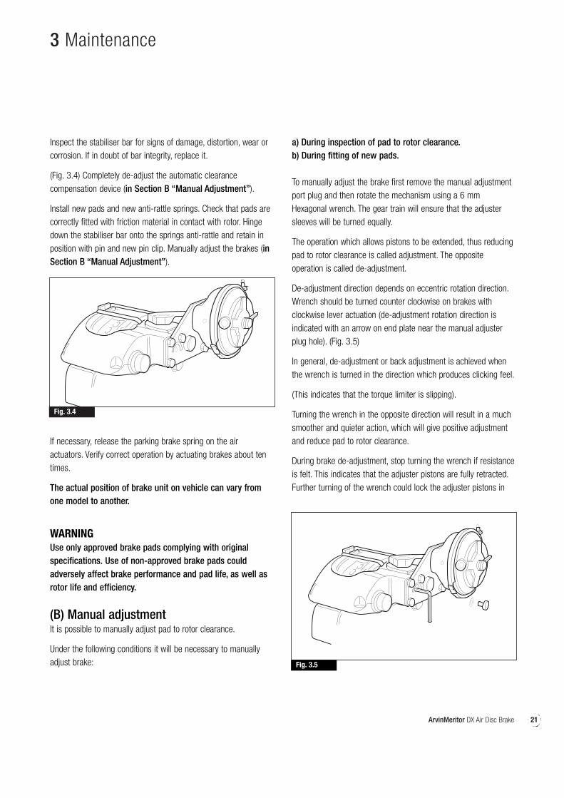
WARNING :This operation requires the caliper to be moved on its slidepins. Extreme care must be taken to avoid trapping fingers.
(Fig. 3.3) Clean the 8 pad support plates in the saddle with a wirebrush removing any build-up of debris or rust. This allows thenew pads to be correctly seated in position.
21ArvinMeritor DX Air Disc Brake
3 Maintenance
Fig. 3.4
Fig. 3.5
Inspect the stabiliser bar for signs of damage, distortion, wear orcorrosion. If in doubt of bar integrity, replace it.
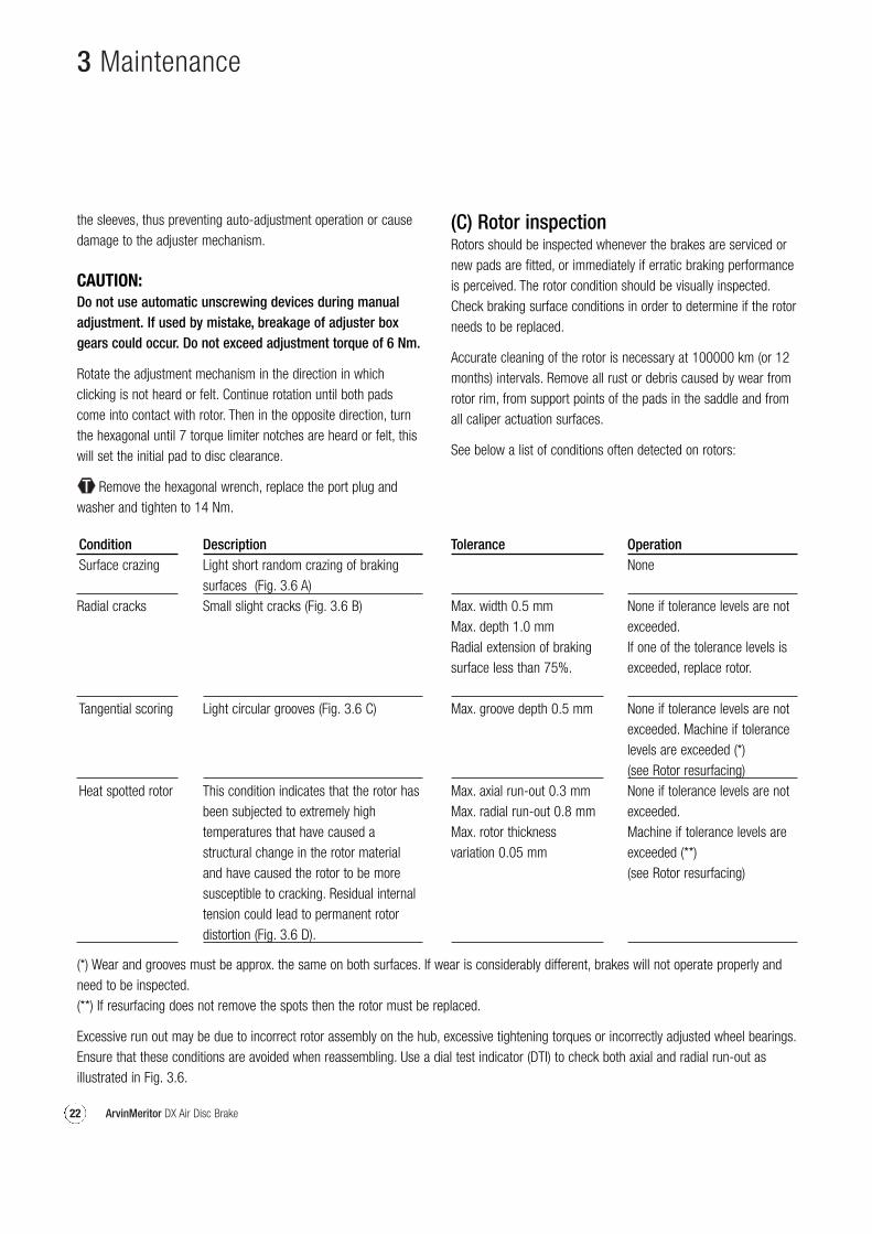
(Fig. 3.4) Completely de-adjust the automatic clearancecompensation device (in Section B “Manual Adjustment”).
Install new pads and new anti-rattle springs. Check that pads arecorrectly fitted with friction material in contact with rotor. Hingedown the stabiliser bar onto the springs anti-rattle and retain inposition with pin and new pin clip. Manually adjust the brakes (inSection B “Manual Adjustment”).
If necessary, release the parking brake spring on the airactuators. Verify correct operation by actuating brakes about tentimes.
The actual position of brake unit on vehicle can vary fromone model to another.
WARNINGUse only approved brake pads complying with originalspecifications. Use of non-approved brake pads couldadversely affect brake performance and pad life, as well asrotor life and efficiency.
(B) Manual adjustmentIt is possible to manually adjust pad to rotor clearance.
Under the following conditions it will be necessary to manuallyadjust brake:
a) During inspection of pad to rotor clearance.b) During fitting of new pads.
To manually adjust the brake first remove the manual adjustmentport plug and then rotate the mechanism using a 6 mmHexagonal wrench. The gear train will ensure that the adjustersleeves will be turned equally.
The operation which allows pistons to be extended, thus reducingpad to rotor clearance is called adjustment. The oppositeoperation is called de-adjustment.
De-adjustment direction depends on eccentric rotation direction.Wrench should be turned counter clockwise on brakes withclockwise lever actuation (de-adjustment rotation direction isindicated with an arrow on end plate near the manual adjusterplug hole). (Fig. 3.5)
In general, de-adjustment or back adjustment is achieved whenthe wrench is turned in the direction which produces clicking feel.
(This indicates that the torque limiter is slipping).
Turning the wrench in the opposite direction will result in a muchsmoother and quieter action, which will give positive adjustmentand reduce pad to rotor clearance.
During brake de-adjustment, stop turning the wrench if resistanceis felt. This indicates that the adjuster pistons are fully retracted.Further turning of the wrench could lock the adjuster pistons in
22 ArvinMeritor DX Air Disc Brake
3 Maintenance
the sleeves, thus preventing auto-adjustment operation or causedamage to the adjuster mechanism.
CAUTION:Do not use automatic unscrewing devices during manualadjustment. If used by mistake, breakage of adjuster boxgears could occur. Do not exceed adjustment torque of 6 Nm.
Rotate the adjustment mechanism in the direction in whichclicking is not heard or felt. Continue rotation until both padscome into contact with rotor. Then in the opposite direction, turnthe hexagonal until 7 torque limiter notches are heard or felt, thiswill set the initial pad to disc clearance.
Remove the hexagonal wrench, replace the port plug andwasher and tighten to 14 Nm.
(C) Rotor inspectionRotors should be inspected whenever the brakes are serviced ornew pads are fitted, or immediately if erratic braking performanceis perceived. The rotor condition should be visually inspected.Check braking surface conditions in order to determine if the rotorneeds to be replaced.
Accurate cleaning of the rotor is necessary at 100000 km (or 12months) intervals. Remove all rust or debris caused by wear fromrotor rim, from support points of the pads in the saddle and fromall caliper actuation surfaces.
See below a list of conditions often detected on rotors:
ConditionSurface crazing
Radial cracks
Tangential scoring
Heat spotted rotor
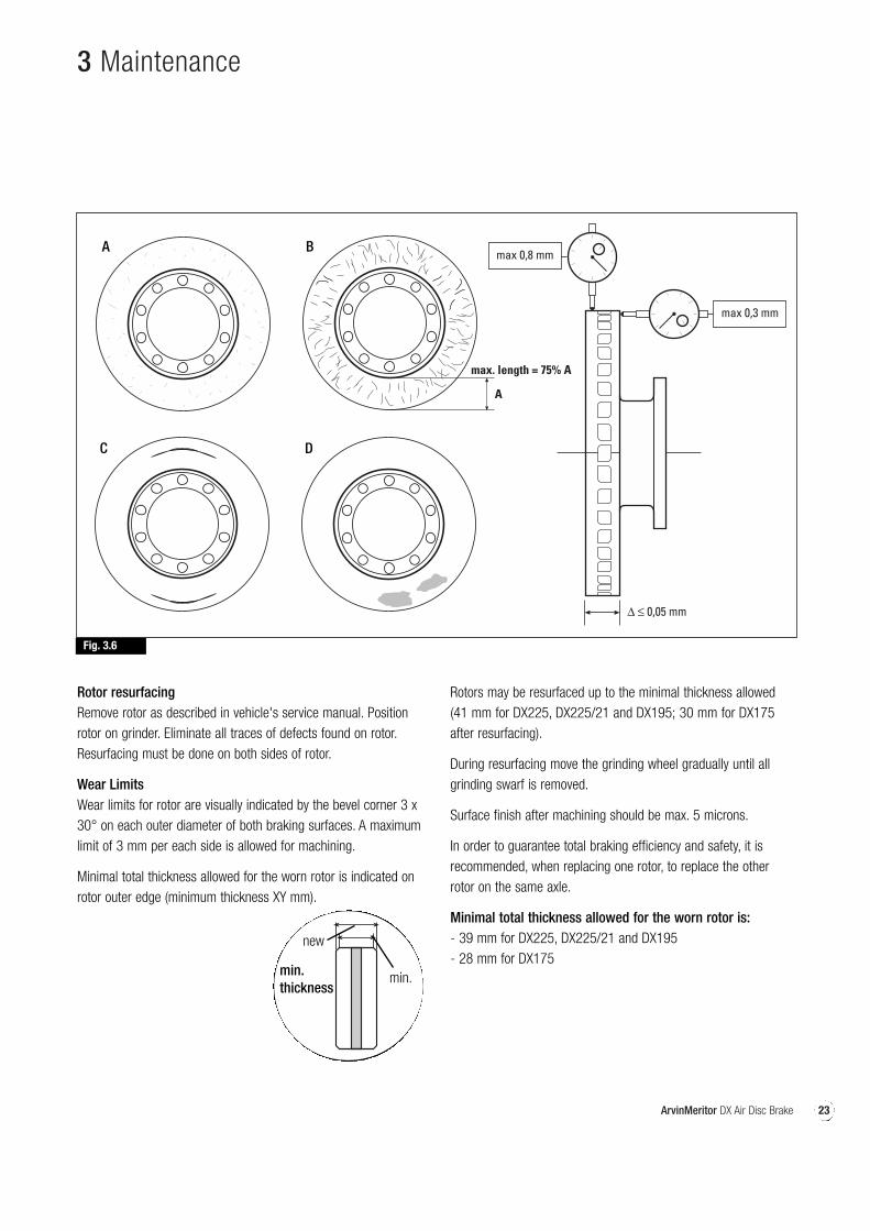
DescriptionLight short random crazing of brakingsurfaces (Fig. 3.6 A)Small slight cracks (Fig. 3.6 B)
Light circular grooves (Fig. 3.6 C)
This condition indicates that the rotor hasbeen subjected to extremely hightemperatures that have caused astructural change in the rotor materialand have caused the rotor to be moresusceptible to cracking. Residual internaltension could lead to permanent rotordistortion (Fig. 3.6 D).
Tolerance
Max. width 0.5 mmMax. depth 1.0 mmRadial extension of brakingsurface less than 75%.
Max. groove depth 0.5 mm
Max. axial run-out 0.3 mmMax. radial run-out 0.8 mmMax. rotor thicknessvariation 0.05 mm
OperationNone
None if tolerance levels are notexceeded.If one of the tolerance levels isexceeded, replace rotor.
None if tolerance levels are notexceeded. Machine if tolerancelevels are exceeded (*) (see Rotor resurfacing)None if tolerance levels are notexceeded.Machine if tolerance levels areexceeded (**)(see Rotor resurfacing)
(*) Wear and grooves must be approx. the same on both surfaces. If wear is considerably different, brakes will not operate properly andneed to be inspected.(**) If resurfacing does not remove the spots then the rotor must be replaced.
Excessive run out may be due to incorrect rotor assembly on the hub, excessive tightening torques or incorrectly adjusted wheel bearings.Ensure that these conditions are avoided when reassembling. Use a dial test indicator (DTI) to check both axial and radial run-out asillustrated in Fig. 3.6.
23ArvinMeritor DX Air Disc Brake
3 Maintenance
Rotor resurfacingRemove rotor as described in vehicle's service manual. Positionrotor on grinder. Eliminate all traces of defects found on rotor.Resurfacing must be done on both sides of rotor.
Wear LimitsWear limits for rotor are visually indicated by the bevel corner 3 x30° on each outer diameter of both braking surfaces. A maximumlimit of 3 mm per each side is allowed for machining.
Minimal total thickness allowed for the worn rotor is indicated onrotor outer edge (minimum thickness XY mm).
Fig. 3.6
A
max. length = 75% A
A B
DC
Rotors may be resurfaced up to the minimal thickness allowed(41 mm for DX225, DX225/21 and DX195; 30 mm for DX175after resurfacing).
During resurfacing move the grinding wheel gradually until allgrinding swarf is removed.
Surface finish after machining should be max. 5 microns.
In order to guarantee total braking efficiency and safety, it isrecommended, when replacing one rotor, to replace the otherrotor on the same axle.
Minimal total thickness allowed for the worn rotor is:- 39 mm for DX225, DX225/21 and DX195- 28 mm for DX175
min.thickness
new
min.
24 ArvinMeritor DX Air Disc Brake
3 Maintenance
(D) Automatic adjuster operating tests
Pad wear compensation device check (on vehicle)This procedure will check function of Automatic adjustermechanism.
WARNINGThe operation must be performed on vehicle. Follow allsafety precautions and abide by standing regulationsconcerning vehicle hoisting and workshop conditions. Thevehicle must be hoisted and the relative wheel of the deviceto be tested should be removed.
Clean the area where the operation will be performed.
WARNINGDo not use compressed air. Linings are non-asbestos butlining dust is an irritant if inhaled and is harmful to health.The use of a vacuum cleaner is highly recommended toeliminate build up of dust. Otherwise, remove dust withwater-dampened shop towels.
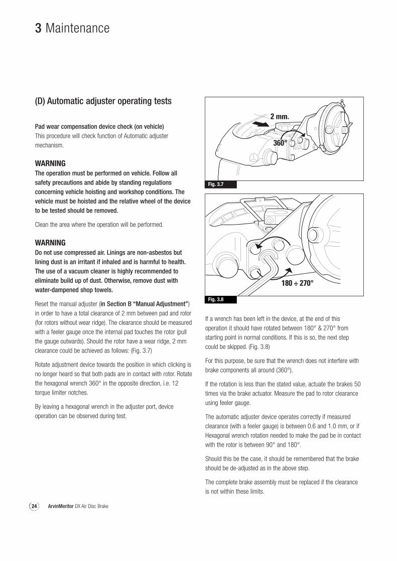
Reset the manual adjuster (in Section B “Manual Adjustment”)in order to have a total clearance of 2 mm between pad and rotor(for rotors without wear ridge). The clearance should be measuredwith a feeler gauge once the internal pad touches the rotor (pullthe gauge outwards). Should the rotor have a wear ridge, 2 mmclearance could be achieved as follows: (Fig. 3.7)
Rotate adjustment device towards the position in which clicking isno longer heard so that both pads are in contact with rotor. Rotatethe hexagonal wrench 360° in the opposite direction, i.e. 12torque limiter notches.
By leaving a hexagonal wrench in the adjuster port, deviceoperation can be observed during test.
If a wrench has been left in the device, at the end of thisoperation it should have rotated between 180° & 270° fromstarting point in normal conditions. If this is so, the next stepcould be skipped. (Fig. 3.8)
For this purpose, be sure that the wrench does not interfere withbrake components all around (360°).
If the rotation is less than the stated value, actuate the brakes 50times via the brake actuator. Measure the pad to rotor clearanceusing feeler gauge.
The automatic adjuster device operates correctly if measuredclearance (with a feeler gauge) is between 0.6 and 1.0 mm, or ifHexagonal wrench rotation needed to make the pad be in contactwith the rotor is between 90° and 180°.
Should this be the case, it should be remembered that the brakeshould be de-adjusted as in the above step.
The complete brake assembly must be replaced if the clearanceis not within these limits.
Fig. 3.7
Fig. 3.8
25ArvinMeritor DX Air Disc Brake
3 Maintenance
(E) checking slide pin bush wearThe following is a check that enables the wear on the slide pinmechanism to be checked with the brake assembly in position onthe vehicle and to determine if replacement is necessary.
Periodical checks of the slide pin bush wear should take place.The frequency of the periodical checks must be determined bythe vehicle/trailer user. However a frequency of every 12 monthsor 100000 kilometres must be considered although the frequencywill depend on the type of operation or the environmentalconditions.
With the aid of a DTI (Dial Test Indicator), movement of the brakehousing relative to the fixing saddle can be measured.
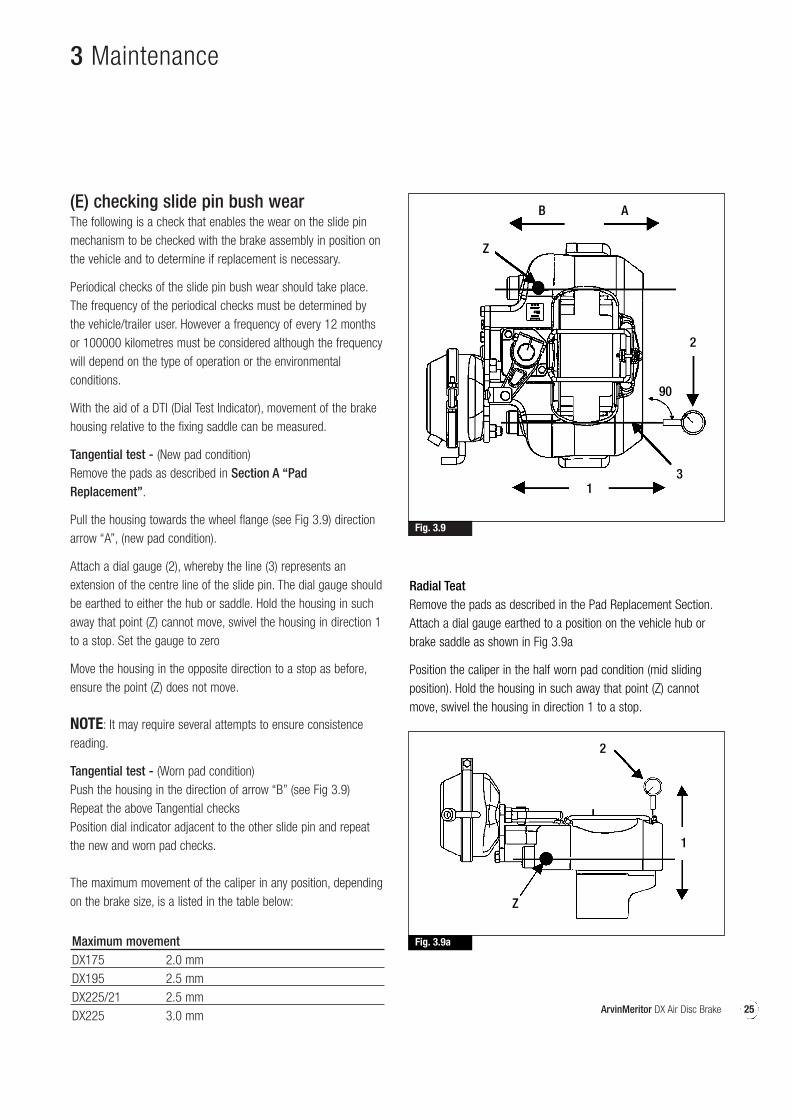
Tangential test - (New pad condition)Remove the pads as described in Section A “PadReplacement”.
Pull the housing towards the wheel flange (see Fig 3.9) directionarrow “A”, (new pad condition).
Attach a dial gauge (2), whereby the line (3) represents anextension of the centre line of the slide pin. The dial gauge shouldbe earthed to either the hub or saddle. Hold the housing in suchaway that point (Z) cannot move, swivel the housing in direction 1to a stop. Set the gauge to zero
Move the housing in the opposite direction to a stop as before,ensure the point (Z) does not move.
NOTE: It may require several attempts to ensure consistencereading.
Tangential test - (Worn pad condition)Push the housing in the direction of arrow “B” (see Fig 3.9)Repeat the above Tangential checksPosition dial indicator adjacent to the other slide pin and repeatthe new and worn pad checks.
The maximum movement of the caliper in any position, dependingon the brake size, is a listed in the table below:
Maximum movement DX175 2.0 mmDX195 2.5 mmDX225/21 2.5 mmDX225 3.0 mm
Fig. 3.9
Fig. 3.9a
Radial TeatRemove the pads as described in the Pad Replacement Section.Attach a dial gauge earthed to a position on the vehicle hub orbrake saddle as shown in Fig 3.9a
Position the caliper in the half worn pad condition (mid slidingposition). Hold the housing in such away that point (Z) cannotmove, swivel the housing in direction 1 to a stop.
B
1
1
2
Z
3
2
90
A
Z
26 ArvinMeritor DX Air Disc Brake
3 Maintenance
Set the gauge to zero. Swivel the housing in the opposite directionas far as possible using only light hand pressure, ensure the point(Z) does not move.
NOTE: It may require several attempts to ensure consistencereading.
The maximum movement of the caliper in any position, dependingon the brake size, is a listed in the table below:
Maximum movement DX175 2.0 mmDX195 2.5 mmDX225/21 2.5 mmDX225 4.0 mm
If movement of the frame exceeds the above figure, then the slidepin and bush mechanism requires attention as detailed in Section H “Slide Pin & Slide pin Bush Replacement”.
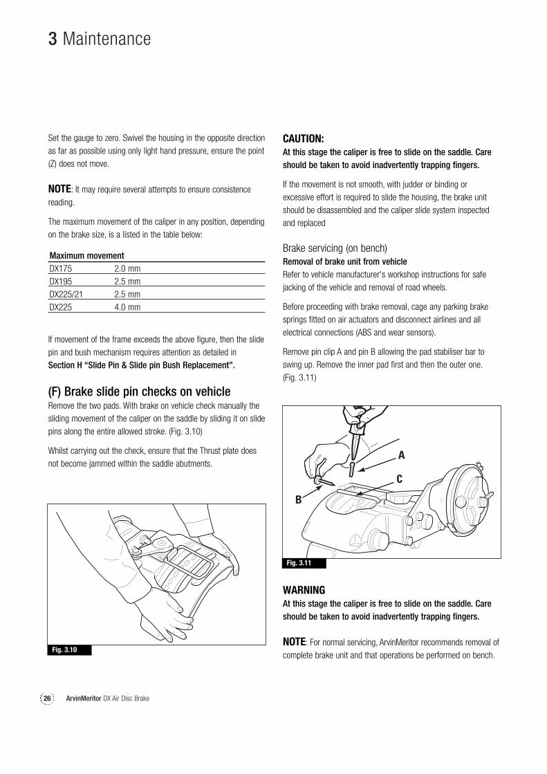
(F) Brake slide pin checks on vehicleRemove the two pads. With brake on vehicle check manually thesliding movement of the caliper on the saddle by sliding it on slidepins along the entire allowed stroke. (Fig. 3.10)
Whilst carrying out the check, ensure that the Thrust plate doesnot become jammed within the saddle abutments.
CAUTION: At this stage the caliper is free to slide on the saddle. Careshould be taken to avoid inadvertently trapping fingers.
If the movement is not smooth, with judder or binding orexcessive effort is required to slide the housing, the brake unitshould be disassembled and the caliper slide system inspectedand replaced
Brake servicing (on bench)Removal of brake unit from vehicleRefer to vehicle manufacturer's workshop instructions for safejacking of the vehicle and removal of road wheels.
Before proceeding with brake removal, cage any parking brakesprings fitted on air actuators and disconnect airlines and allelectrical connections (ABS and wear sensors).
Remove pin clip A and pin B allowing the pad stabiliser bar toswing up. Remove the inner pad first and then the outer one.(Fig. 3.11)
Fig. 3.10
Fig. 3.11
WARNINGAt this stage the caliper is free to slide on the saddle. Careshould be taken to avoid inadvertently trapping fingers.
NOTE: For normal servicing, ArvinMeritor recommends removal ofcomplete brake unit and that operations be performed on bench.
27ArvinMeritor DX Air Disc Brake
3 Maintenance
Fig. 3.12
Fig. 3.13
Fig. 3.14
In extreme cases of rotor wear it could be difficult to remove padsbecause of rotor ridges. Manual de-adjusting of the brakes shallbe necessary. (See Section “Manual Adjustment”)
As very high torques is required, the mounting device should beclamped onto a sturdy workbench.
Remove saddle to axle / flange retaining screws.
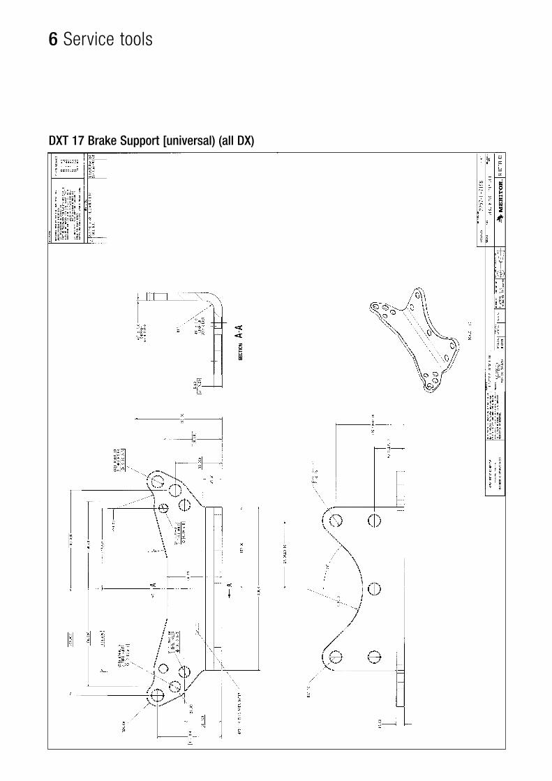
Remove brake from vehicle and secure it to a bench mountedbracket using the same fixings as on the vehicle. Service tool(DXT17) (Fig. 3.12)
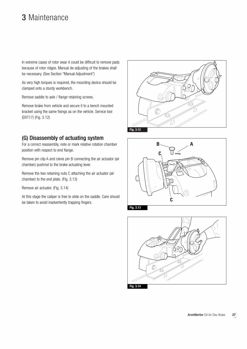
(G) Disassembly of actuating systemFor a correct reassembly, note or mark relative rotation chamberposition with respect to end flange.
Remove pin clip A and clevis pin B connecting the air actuator (airchamber) pushrod to the brake actuating lever.
Remove the two retaining nuts C attaching the air actuator (airchamber) to the end plate. (Fig. 3.13)
Remove air actuator. (Fig. 3.14)
At this stage the caliper is free to slide on the saddle. Care shouldbe taken to avoid inadvertently trapping fingers.
28 ArvinMeritor DX Air Disc Brake
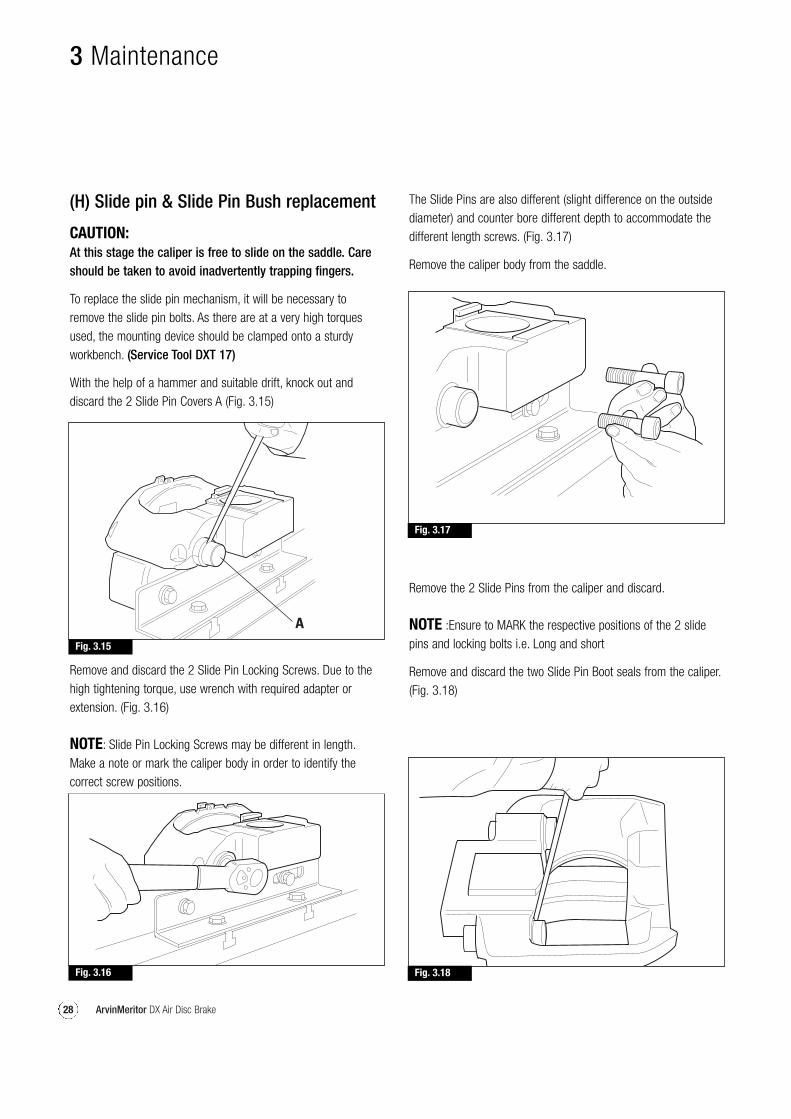
(H) Slide pin & Slide Pin Bush replacement
CAUTION:At this stage the caliper is free to slide on the saddle. Careshould be taken to avoid inadvertently trapping fingers.
To replace the slide pin mechanism, it will be necessary toremove the slide pin bolts. As there are at a very high torquesused, the mounting device should be clamped onto a sturdyworkbench. (Service Tool DXT 17)
With the help of a hammer and suitable drift, knock out anddiscard the 2 Slide Pin Covers A (Fig. 3.15)
Fig. 3.15
A
Fig. 3.17
Fig. 3.16 Fig. 3.18
Remove and discard the 2 Slide Pin Locking Screws. Due to thehigh tightening torque, use wrench with required adapter orextension. (Fig. 3.16)
NOTE: Slide Pin Locking Screws may be different in length.Make a note or mark the caliper body in order to identify thecorrect screw positions.
The Slide Pins are also different (slight difference on the outsidediameter) and counter bore different depth to accommodate thedifferent length screws. (Fig. 3.17)
Remove the caliper body from the saddle.
Remove the 2 Slide Pins from the caliper and discard.
NOTE :Ensure to MARK the respective positions of the 2 slidepins and locking bolts i.e. Long and short
Remove and discard the two Slide Pin Boot seals from the caliper.(Fig. 3.18)
3 Maintenance
29ArvinMeritor DX Air Disc Brake
Fig. 3.19 Fig. 3.20
Fig. 3.21
Fig. 3.22
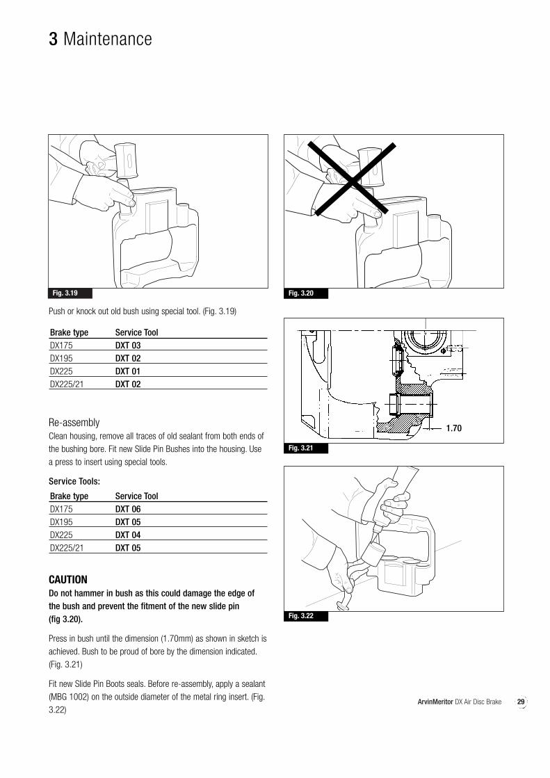
Push or knock out old bush using special tool. (Fig. 3.19)
Brake type Service ToolDX175 DXT 03DX195 DXT 02DX225 DXT 01DX225/21 DXT 02
Re-assemblyClean housing, remove all traces of old sealant from both ends ofthe bushing bore. Fit new Slide Pin Bushes into the housing. Usea press to insert using special tools.
Service Tools:
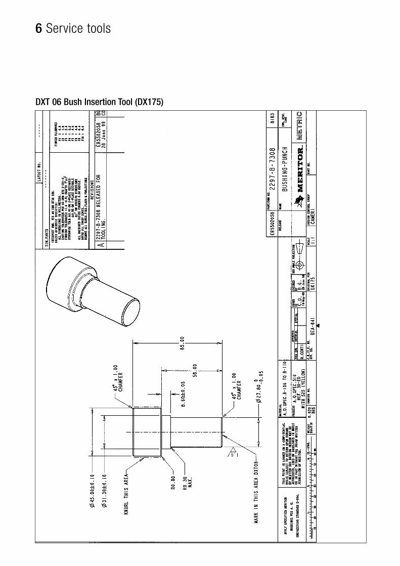
Brake type Service ToolDX175 DXT 06DX195 DXT 05DX225 DXT 04DX225/21 DXT 05
CAUTIONDo not hammer in bush as this could damage the edge ofthe bush and prevent the fitment of the new slide pin (fig 3.20).
Press in bush until the dimension (1.70mm) as shown in sketch isachieved. Bush to be proud of bore by the dimension indicated.(Fig. 3.21)
Fit new Slide Pin Boots seals. Before re-assembly, apply a sealant(MBG 1002) on the outside diameter of the metal ring insert. (Fig.3.22)
3 Maintenance
1.70
30 ArvinMeritor DX Air Disc Brake
3 Maintenance
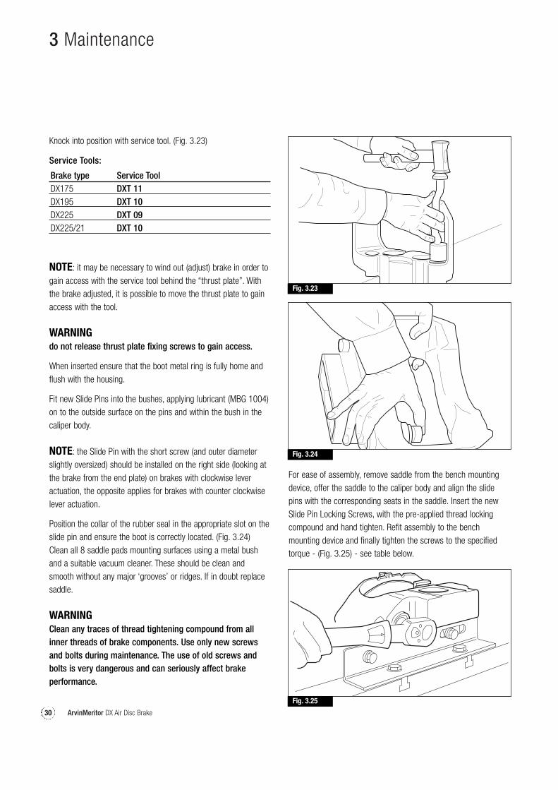
Knock into position with service tool. (Fig. 3.23)
Service Tools:
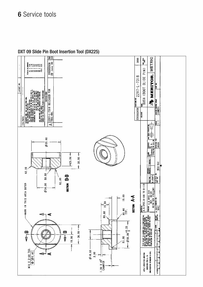
Brake type Service ToolDX175 DXT 11DX195 DXT 10DX225 DXT 09DX225/21 DXT 10
NOTE: it may be necessary to wind out (adjust) brake in order togain access with the service tool behind the “thrust plate”. Withthe brake adjusted, it is possible to move the thrust plate to gainaccess with the tool.
WARNINGdo not release thrust plate fixing screws to gain access.
When inserted ensure that the boot metal ring is fully home andflush with the housing.
Fit new Slide Pins into the bushes, applying lubricant (MBG 1004)on to the outside surface on the pins and within the bush in thecaliper body.
NOTE: the Slide Pin with the short screw (and outer diameterslightly oversized) should be installed on the right side (looking atthe brake from the end plate) on brakes with clockwise leveractuation, the opposite applies for brakes with counter clockwiselever actuation.
Position the collar of the rubber seal in the appropriate slot on theslide pin and ensure the boot is correctly located. (Fig. 3.24)Clean all 8 saddle pads mounting surfaces using a metal bushand a suitable vacuum cleaner. These should be clean andsmooth without any major ‘grooves’ or ridges. If in doubt replacesaddle.
WARNINGClean any traces of thread tightening compound from allinner threads of brake components. Use only new screwsand bolts during maintenance. The use of old screws andbolts is very dangerous and can seriously affect brakeperformance.
Fig. 3.23
Fig. 3.24
Fig. 3.25
For ease of assembly, remove saddle from the bench mountingdevice, offer the saddle to the caliper body and align the slidepins with the corresponding seats in the saddle. Insert the newSlide Pin Locking Screws, with the pre-applied thread lockingcompound and hand tighten. Refit assembly to the benchmounting device and finally tighten the screws to the specifiedtorque - (Fig. 3.25) - see table below.
31ArvinMeritor DX Air Disc Brake
3 Maintenance
Fig. 3.27
Fig. 3.26
DX 175 240 Nm +/- 15 Nm (Torx head 200 Nm +/- 10 Nm)
DX 195 340 Nm +/- 20 NmDX 225 500 Nm +/- 25 NmDX 225/21 340 Nm +/- 20 Nm
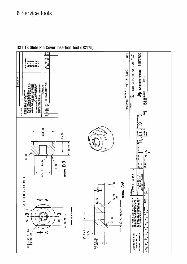
After torque tightening the locking screws, ensure that the caliperslides freely on the slide pins. Install new slide pin caps. Beforereassemble, apply a small bead of sealant (MBG 1002) to theedge of the new Slide Pin Cap. Push or knock end caps intoposition using service tool (Fig. 3.26)
Brake type Service ToolDX175 DXT 18DX195 DXT 12DX225 DXT 12DX225/21 DXT 12
Ensure that the caps are fully located. Refit brake to the axle.
NOTE: Follow the axle manufacturer’s service instructions forfitment of caliper to axle flange.
Refit brake actuator. Refit new clevis pin and pin clip.
Follow Section (A) “Pad replacement”Follow Section (C) “Manual adjustment”
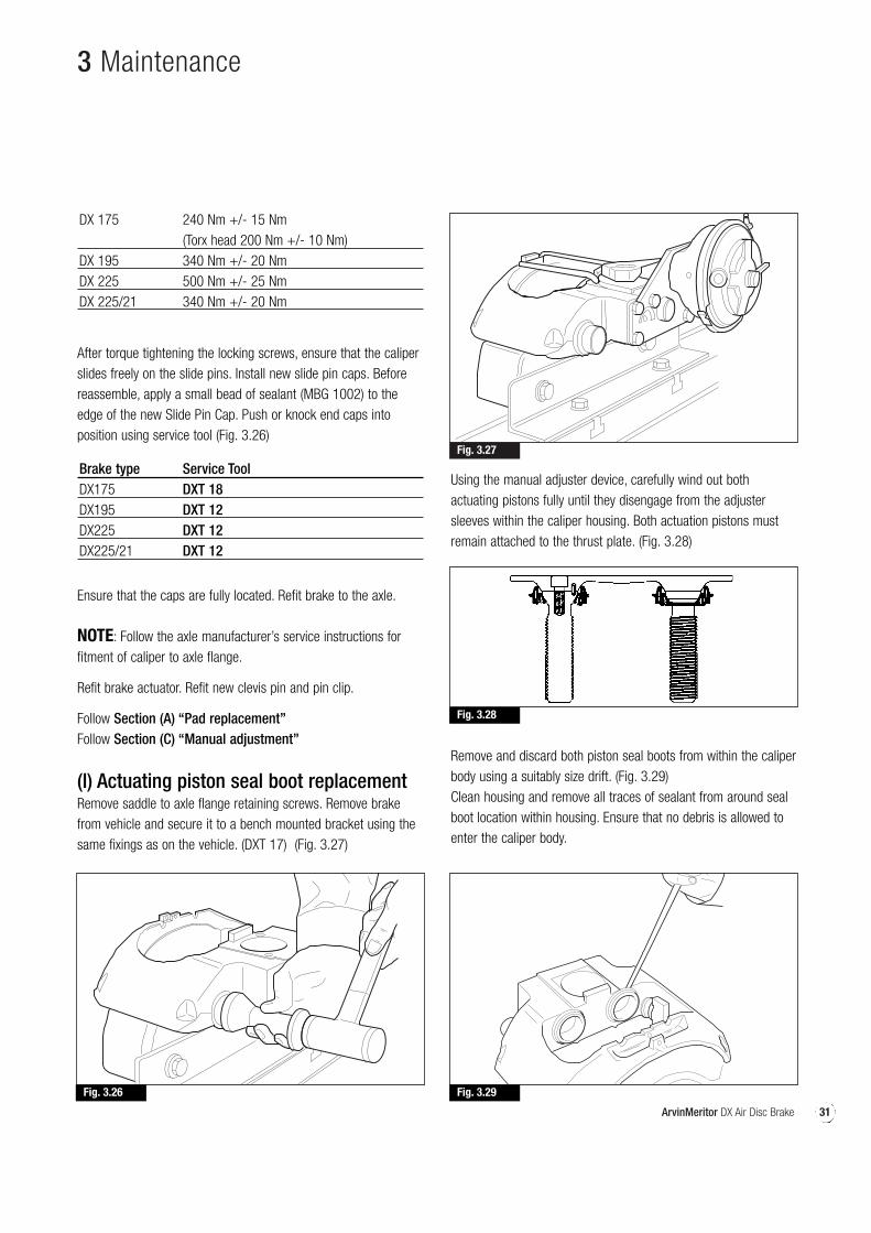
(I) Actuating piston seal boot replacementRemove saddle to axle flange retaining screws. Remove brakefrom vehicle and secure it to a bench mounted bracket using thesame fixings as on the vehicle. (DXT 17) (Fig. 3.27)
Using the manual adjuster device, carefully wind out bothactuating pistons fully until they disengage from the adjustersleeves within the caliper housing. Both actuation pistons mustremain attached to the thrust plate. (Fig. 3.28)
Remove and discard both piston seal boots from within the caliperbody using a suitably size drift. (Fig. 3.29) Clean housing and remove all traces of sealant from around sealboot location within housing. Ensure that no debris is allowed toenter the caliper body.
Fig. 3.29
Fig. 3.28
32 ArvinMeritor DX Air Disc Brake
3 Maintenance
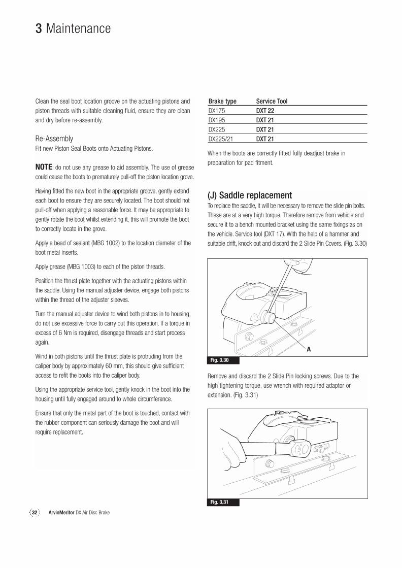
(J) Saddle replacementTo replace the saddle, it will be necessary to remove the slide pin bolts.These are at a very high torque. Therefore remove from vehicle andsecure it to a bench mounted bracket using the same fixings as onthe vehicle. Service tool (DXT 17). With the help of a hammer andsuitable drift, knock out and discard the 2 Slide Pin Covers. (Fig. 3.30)
Remove and discard the 2 Slide Pin locking screws. Due to thehigh tightening torque, use wrench with required adaptor orextension. (Fig. 3.31)
Fig. 3.30
A
Fig. 3.31
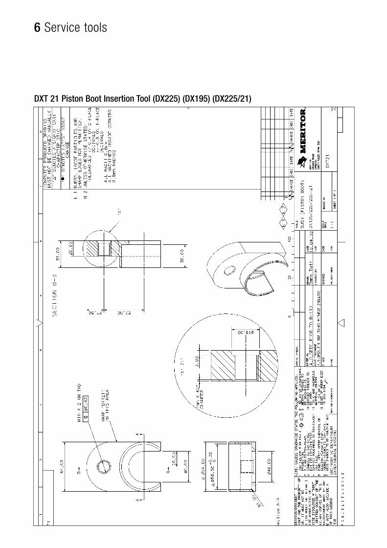
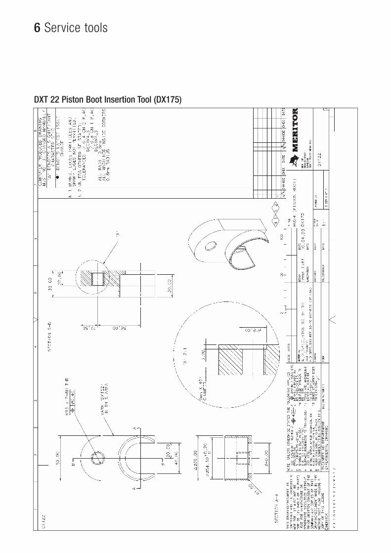
Brake type Service ToolDX175 DXT 22DX195 DXT 21DX225 DXT 21DX225/21 DXT 21
When the boots are correctly fitted fully deadjust brake inpreparation for pad fitment.
Clean the seal boot location groove on the actuating pistons andpiston threads with suitable cleaning fluid, ensure they are cleanand dry before re-assembly.
Re-AssemblyFit new Piston Seal Boots onto Actuating Pistons.
NOTE: do not use any grease to aid assembly. The use of greasecould cause the boots to prematurely pull-off the piston location grove.
Having fitted the new boot in the appropriate groove, gently extendeach boot to ensure they are securely located. The boot should notpull-off when applying a reasonable force. It may be appropriate togently rotate the boot whilst extending it, this will promote the bootto correctly locate in the grove.
Apply a bead of sealant (MBG 1002) to the location diameter of theboot metal inserts.
Apply grease (MBG 1003) to each of the piston threads.
Position the thrust plate together with the actuating pistons withinthe saddle. Using the manual adjuster device, engage both pistonswithin the thread of the adjuster sleeves.
Turn the manual adjuster device to wind both pistons in to housing,do not use excessive force to carry out this operation. If a torque inexcess of 6 Nm is required, disengage threads and start processagain.
Wind in both pistons until the thrust plate is protruding from thecaliper body by approximately 60 mm, this should give sufficientaccess to refit the boots into the caliper body.
Using the appropriate service tool, gently knock in the boot into thehousing until fully engaged around to whole circumference.
Ensure that only the metal part of the boot is touched, contact withthe rubber component can seriously damage the boot and willrequire replacement.
33ArvinMeritor DX Air Disc Brake
3 Maintenance
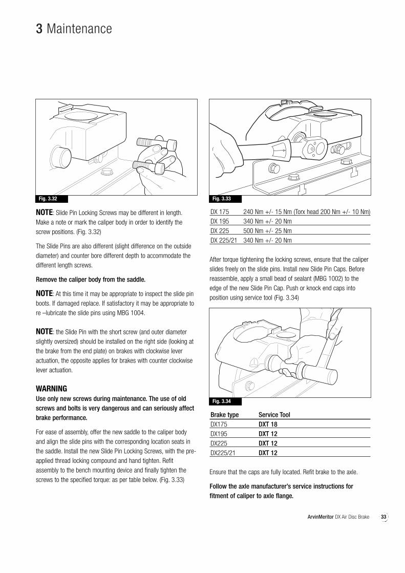
NOTE: Slide Pin Locking Screws may be different in length.Make a note or mark the caliper body in order to identify thescrew positions. (Fig. 3.32)
The Slide Pins are also different (slight difference on the outsidediameter) and counter bore different depth to accommodate thedifferent length screws.
Remove the caliper body from the saddle.
NOTE: At this time it may be appropriate to inspect the slide pinboots. If damaged replace. If satisfactory it may be appropriate tore –lubricate the slide pins using MBG 1004.
NOTE: the Slide Pin with the short screw (and outer diameterslightly oversized) should be installed on the right side (looking atthe brake from the end plate) on brakes with clockwise leveractuation, the opposite applies for brakes with counter clockwiselever actuation.
WARNINGUse only new screws during maintenance. The use of oldscrews and bolts is very dangerous and can seriously affectbrake performance.
For ease of assembly, offer the new saddle to the caliper bodyand align the slide pins with the corresponding location seats inthe saddle. Install the new Slide Pin Locking Screws, with the pre-applied thread locking compound and hand tighten. Refitassembly to the bench mounting device and finally tighten thescrews to the specified torque: as per table below. (Fig. 3.33)
DX 175 240 Nm +/- 15 Nm (Torx head 200 Nm +/- 10 Nm)DX 195 340 Nm +/- 20 NmDX 225 500 Nm +/- 25 NmDX 225/21 340 Nm +/- 20 Nm
After torque tightening the locking screws, ensure that the caliperslides freely on the slide pins. Install new Slide Pin Caps. Beforereassemble, apply a small bead of sealant (MBG 1002) to theedge of the new Slide Pin Cap. Push or knock end caps intoposition using service tool (Fig. 3.34)
Fig. 3.32 Fig. 3.33
Fig. 3.34
Brake type Service ToolDX175 DXT 18DX195 DXT 12DX225 DXT 12DX225/21 DXT 12
Ensure that the caps are fully located. Refit brake to the axle.
Follow the axle manufacturer’s service instructions forfitment of caliper to axle flange.
34 ArvinMeritor DX Air Disc Brake
3 Maintenance
(K) Eccentric shaft & cover platereplacementThe operation can be performed on the vehicle although removalwill facilitate easier working conditions.
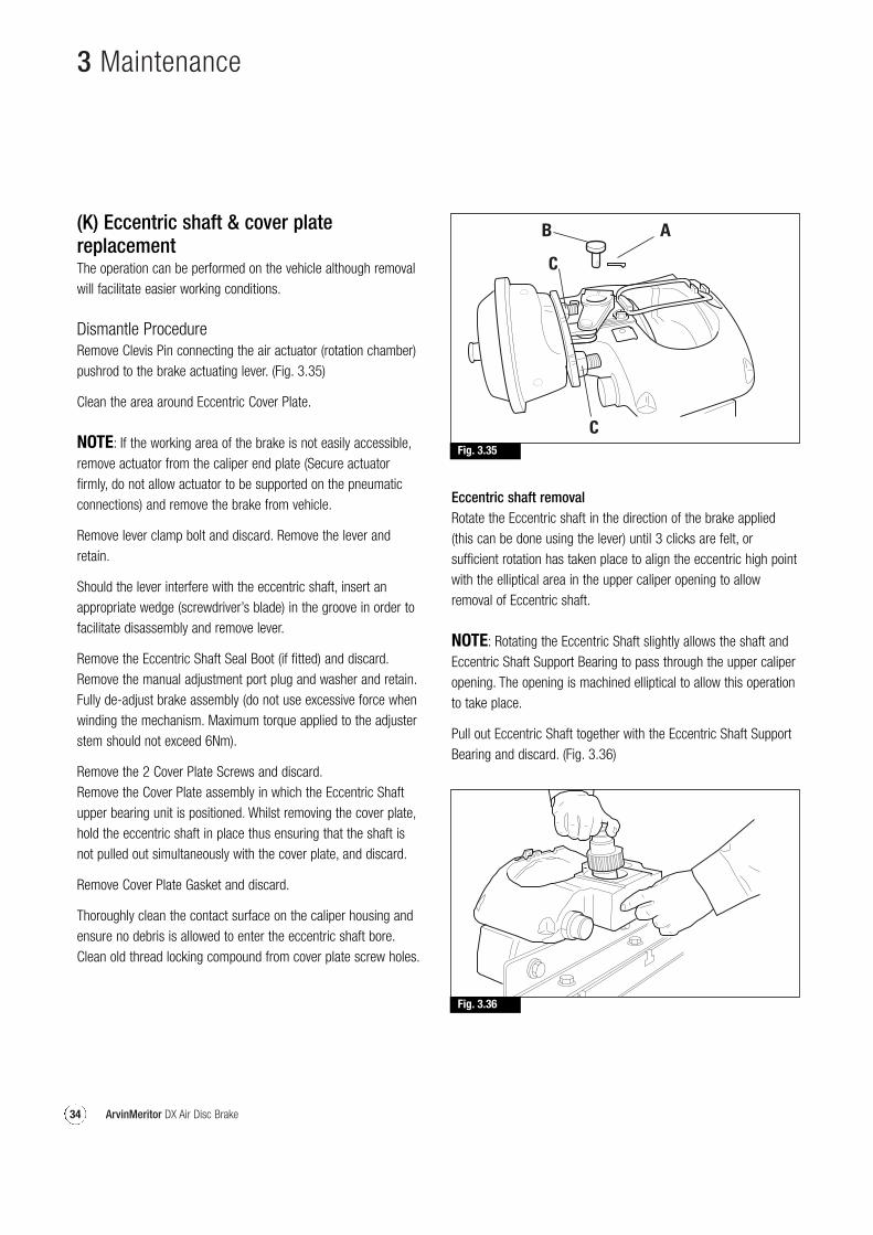
Dismantle ProcedureRemove Clevis Pin connecting the air actuator (rotation chamber)pushrod to the brake actuating lever. (Fig. 3.35)
Clean the area around Eccentric Cover Plate.
NOTE: If the working area of the brake is not easily accessible,remove actuator from the caliper end plate (Secure actuatorfirmly, do not allow actuator to be supported on the pneumaticconnections) and remove the brake from vehicle.
Remove lever clamp bolt and discard. Remove the lever andretain.
Should the lever interfere with the eccentric shaft, insert anappropriate wedge (screwdriver’s blade) in the groove in order tofacilitate disassembly and remove lever.
Remove the Eccentric Shaft Seal Boot (if fitted) and discard.Remove the manual adjustment port plug and washer and retain.Fully de-adjust brake assembly (do not use excessive force whenwinding the mechanism. Maximum torque applied to the adjusterstem should not exceed 6Nm).
Remove the 2 Cover Plate Screws and discard.Remove the Cover Plate assembly in which the Eccentric Shaftupper bearing unit is positioned. Whilst removing the cover plate,hold the eccentric shaft in place thus ensuring that the shaft isnot pulled out simultaneously with the cover plate, and discard.
Remove Cover Plate Gasket and discard.
Thoroughly clean the contact surface on the caliper housing andensure no debris is allowed to enter the eccentric shaft bore.Clean old thread locking compound from cover plate screw holes.
Fig. 3.35
Fig. 3.36
Eccentric shaft removalRotate the Eccentric shaft in the direction of the brake applied(this can be done using the lever) until 3 clicks are felt, orsufficient rotation has taken place to align the eccentric high pointwith the elliptical area in the upper caliper opening to allowremoval of Eccentric shaft.
NOTE: Rotating the Eccentric Shaft slightly allows the shaft andEccentric Shaft Support Bearing to pass through the upper caliperopening. The opening is machined elliptical to allow this operationto take place.
Pull out Eccentric Shaft together with the Eccentric Shaft SupportBearing and discard. (Fig. 3.36)
35ArvinMeritor DX Air Disc Brake
3 Maintenance
NOTE: Care should be taken with the eccentric shaft removedthat no rollers are dislodged from the Lower Eccentric ShaftBearing, as this is an uncaged needle roller bearing assembly.Do not move the manual adjuster stem with the Eccentric shaftremoved as this could cause the Adjuster Gear segment tobecome displaced. The consequence of this would be to make re-assembly more difficult.
Reassembly
Apply lubricating grease (MBG 1003) to the Lower Eccentric ShaftBearing within the housing, taking care not to allow the looseneedle rollers to become displaced.Apply lubricant grease (MBG 1003) to all bearing surfaces of newEccentric Shaft. Open up and position the new Eccentric ShaftSupport Bearing in the seat on the eccentric shaft, and thoroughlylubricate the rollers.
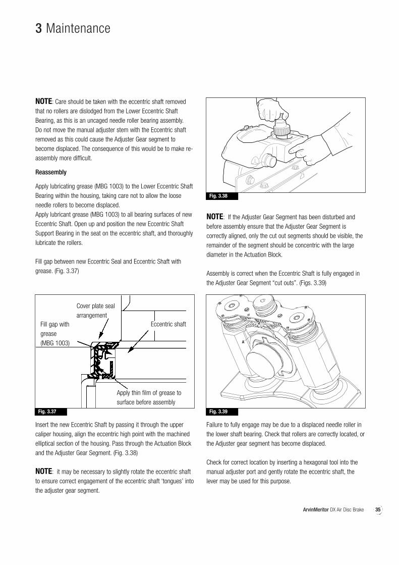
Fill gap between new Eccentric Seal and Eccentric Shaft withgrease. (Fig. 3.37)
Insert the new Eccentric Shaft by passing it through the uppercaliper housing, align the eccentric high point with the machinedelliptical section of the housing. Pass through the Actuation Blockand the Adjuster Gear Segment. (Fig. 3.38)
NOTE: it may be necessary to slightly rotate the eccentric shaftto ensure correct engagement of the eccentric shaft ‘tongues’ intothe adjuster gear segment.
NOTE: If the Adjuster Gear Segment has been disturbed andbefore assembly ensure that the Adjuster Gear Segment iscorrectly aligned, only the cut out segments should be visible, theremainder of the segment should be concentric with the largediameter in the Actuation Block.
Assembly is correct when the Eccentric Shaft is fully engaged inthe Adjuster Gear Segment “cut outs”. (Figs. 3.39)
Failure to fully engage may be due to a displaced needle roller inthe lower shaft bearing. Check that rollers are correctly located, orthe Adjuster gear segment has become displaced.
Check for correct location by inserting a hexagonal tool into themanual adjuster port and gently rotate the eccentric shaft, thelever may be used for this purpose.
Fig. 3.38
Fig. 3.37
Fill gap withgrease(MBG 1003)
Apply thin film of grease tosurface before assembly
Cover plate sealarrangement
Eccentric shaft
Fig. 3.39
36 ArvinMeritor DX Air Disc Brake
The hexagonal drive should rotate in one direction only inresponse to the rotation of the eccentric shaft. Failure to do soindicates that the ‘eccentric shaft tongues’ are not correctlyengaged, therefore the assembly process should be repeated.
Thoroughly apply lubricant grease (MBG 1003) to needle rollerbearing in the new Cover Plate assembly, taking care not to allowneedle rollers to become displaced, at the same time, smear athin film of grease (MBG 1003) to the inside diameter of the coverplate seal.
Apply a small bead of sealant (MBG 1002) on both sides of thepaper gasket. Position gasket on the cover plate and install thecover plate into the housing securing it with 2 new screws (withthread locking compound previously applied) and tighten to a
torque of 35 Nm.
Install lever making sure that the marks on the lever andeccentric are aligned (Fig. 3-44).
NOTE: Lever is in correct position when it completely engages inthe hexagonal section of the eccentric shaft.
Fit new Lever Clamping Bolt and Nut in its seat on the leverand tighten to a torque of 30 Nm.
Manually actuate the lever several times in order to checkadjustment and actuation device operation to ensure allcomponents are fitted correctly.
Refit brake to the axle (if removed).
Follow the axle manufacturer’s service instructions for fitment ofcaliper to axle flange.
Follow Section A “Pad replacement”Follow Section C “Manual adjustment”
(L) Stabiliser bar replacement
This procedure covers the replacement of the stabilizer bar.The operation can be performed on the vehicle although removalwill facilitate easier working conditions.
Preliminary procedures
WARNING:If the caliper is fitted with a spring parking chamber, it isnecessary to disarm the parking spring, following the airactuator manufacturer’s instructions, before working on thebrake. Use care when disarming the parking brake chamber.Personal injury can result if correct procedures are notfollowed.
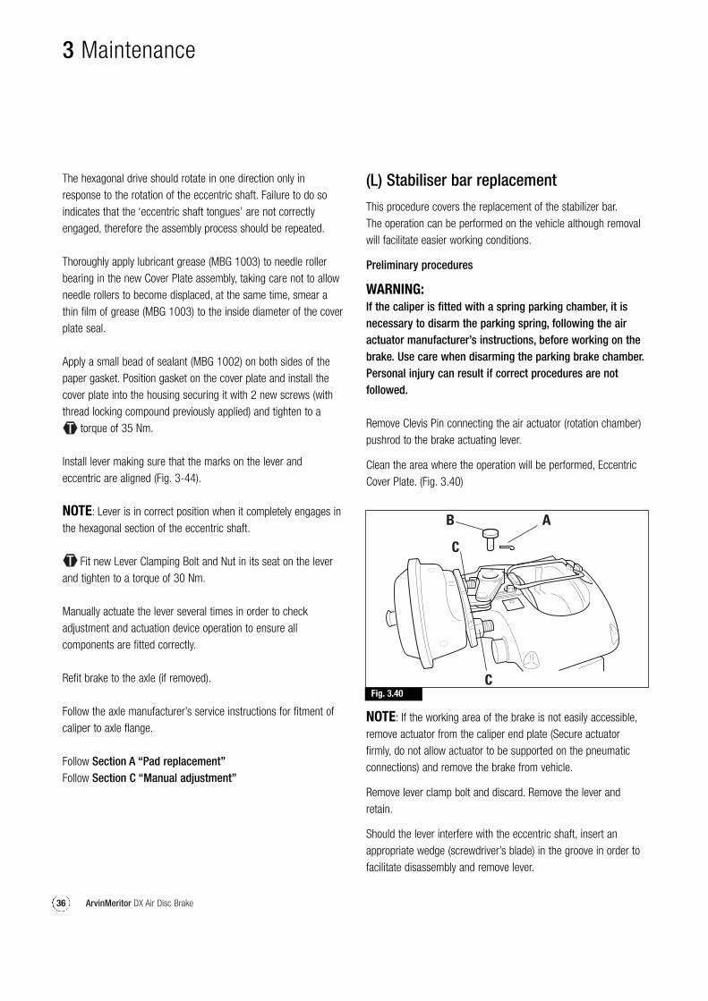
Remove Clevis Pin connecting the air actuator (rotation chamber)pushrod to the brake actuating lever.
Clean the area where the operation will be performed, EccentricCover Plate. (Fig. 3.40)
Fig. 3.40
3 Maintenance
NOTE: If the working area of the brake is not easily accessible,remove actuator from the caliper end plate (Secure actuatorfirmly, do not allow actuator to be supported on the pneumaticconnections) and remove the brake from vehicle.
Remove lever clamp bolt and discard. Remove the lever andretain.
Should the lever interfere with the eccentric shaft, insert anappropriate wedge (screwdriver’s blade) in the groove in order tofacilitate disassembly and remove lever.
37ArvinMeritor DX Air Disc Brake
Fig. 3.41
Fig. 3.42
3 Maintenance
Remove the Eccentric Shaft Seal Boot if fitted. (not used on laterlevel brakes). Remove the manual adjustment port plug andwasher and retain. Remove the 2 Cover Plate Screws and discard.Remove the Cover Plate assembly in which the Eccentric Shaftupper bearing unit is positioned. Whilst removing the cover plate,hold the eccentric shaft in place thus ensuring that the shaft isnot pulled out simultaneously with the cover plate, and discard.
NOTE: Care should be taken when removing the cover plateassembly, that none of the rollers are allowed to becomedislodged from the cover plate bearing. The bearing assembly isan uncaged needle roller bearing.
Remove Cover Plate Gasket and discard. Remove stabiliser bar“A” from housing.
Thoroughly clean the contact surface on the caliper housing.Ensure no debris is allowed to enter the eccentric bore.
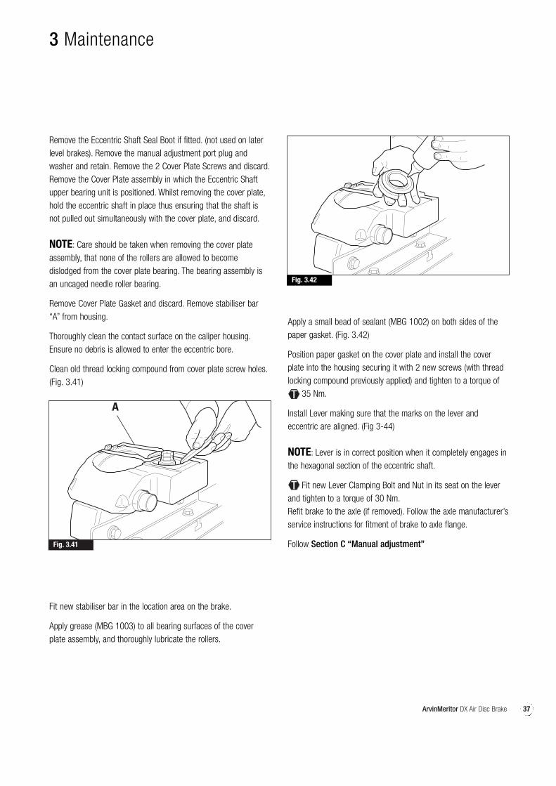
Clean old thread locking compound from cover plate screw holes.(Fig. 3.41)
Fit new stabiliser bar in the location area on the brake.
Apply grease (MBG 1003) to all bearing surfaces of the coverplate assembly, and thoroughly lubricate the rollers.
Apply a small bead of sealant (MBG 1002) on both sides of thepaper gasket. (Fig. 3.42)
Position paper gasket on the cover plate and install the coverplate into the housing securing it with 2 new screws (with threadlocking compound previously applied) and tighten to a torque of
35 Nm.
Install Lever making sure that the marks on the lever andeccentric are aligned. (Fig 3-44)
NOTE: Lever is in correct position when it completely engages inthe hexagonal section of the eccentric shaft.
Fit new Lever Clamping Bolt and Nut in its seat on the leverand tighten to a torque of 30 Nm.Refit brake to the axle (if removed). Follow the axle manufacturer’sservice instructions for fitment of brake to axle flange.
Follow Section C “Manual adjustment”
38 ArvinMeritor DX Air Disc Brake
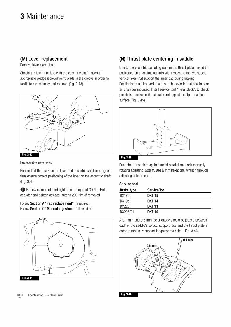
(M) Lever replacementRemove lever clamp bolt.
Should the lever interfere with the eccentric shaft, insert anappropriate wedge (screwdriver’s blade in the groove in order tofacilitate disassembly and remove. (Fig. 3.43)
(N) Thrust plate centering in saddle
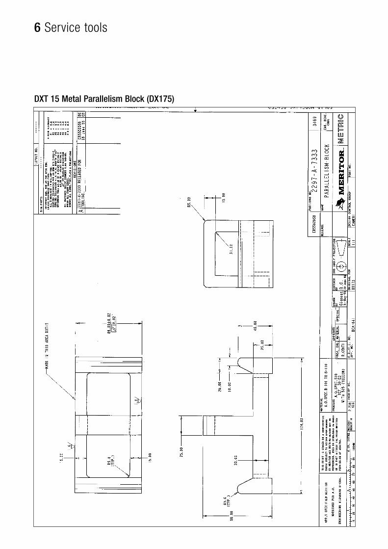
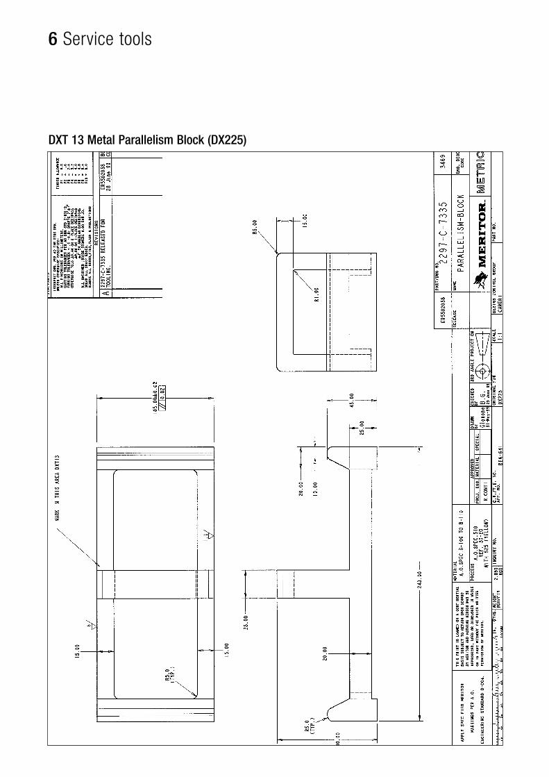
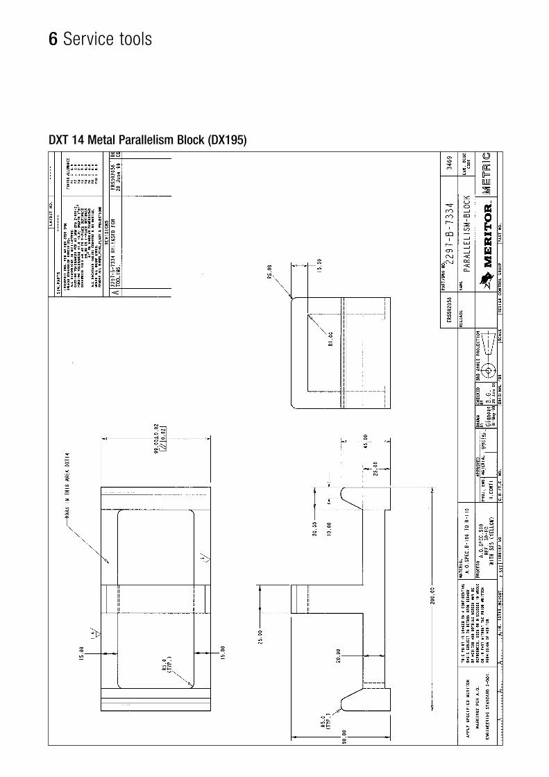
Due to the eccentric actuating system the thrust plate should bepositioned on a longitudinal axis with respect to the two saddlevertical axes that support the inner pad during braking.Positioning must be carried out with the lever in rest position andair chamber mounted. Install service tool “metal block”, to checkparallelism between thrust plate and opposite caliper reactionsurface (Fig. 3.45).
Push the thrust plate against metal parallelism block manuallyrotating adjusting system. Use 6 mm hexagonal wrench throughadjusting hole on end.
Service tool
Brake type Service ToolDX175 DXT 15DX195 DXT 14DX225 DXT 13DX225/21 DXT 16
A 0.1 mm and 0.5 mm feeler gauge should be placed betweeneach of the saddle's vertical support face and the thrust plate inorder to manually support it against the shim. (Fig. 3.46)
Reassemble new lever.
Ensure that the mark on the lever and eccentric shaft are aligned,thus ensure correct positioning of the lever on the eccentric shaft.(Fig. 3.44)
Fit new clamp bolt and tighten to a torque of 30 Nm. Refitactuator and tighten actuator nuts to 200 Nm (if removed)
Follow Section A “Pad replacement” if required.Follow Section C “Manual adjustment” if required.
Fig. 3.43Fig. 3.45
Fig. 3.46
0,5 mm
0,1 mm
Fig. 3.44
3 Maintenance
39ArvinMeritor DX Air Disc Brake
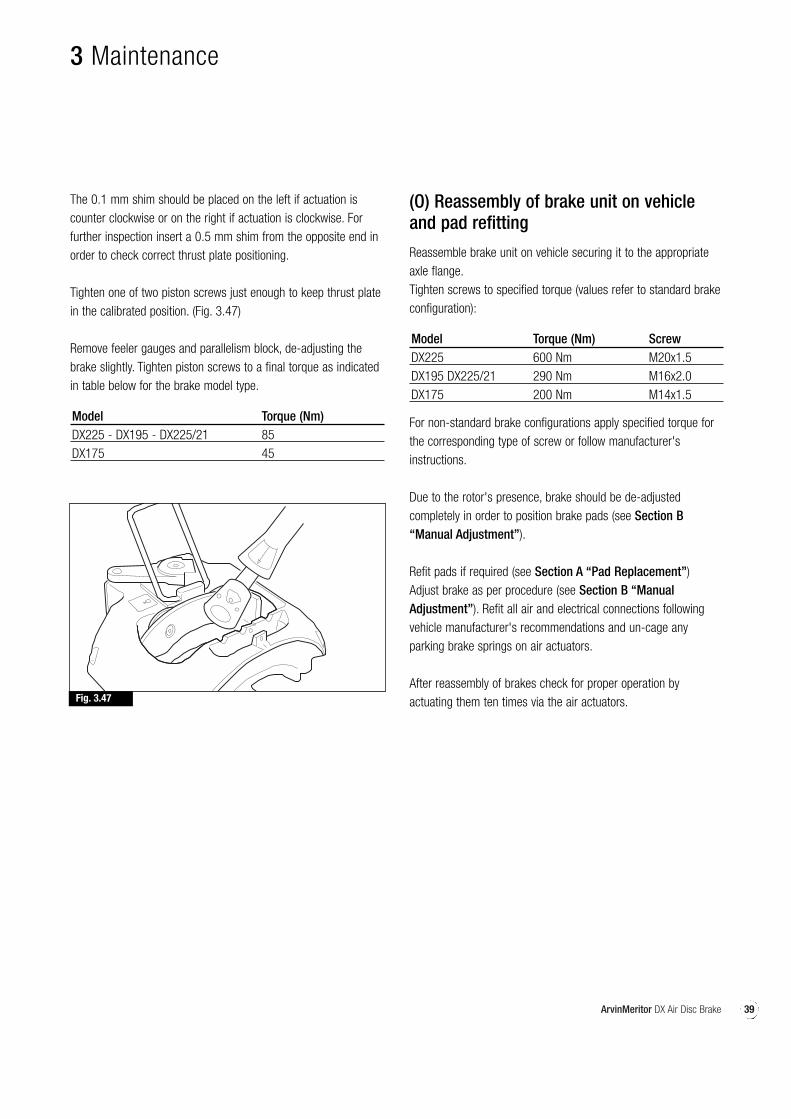
The 0.1 mm shim should be placed on the left if actuation iscounter clockwise or on the right if actuation is clockwise. Forfurther inspection insert a 0.5 mm shim from the opposite end inorder to check correct thrust plate positioning.
Tighten one of two piston screws just enough to keep thrust platein the calibrated position. (Fig. 3.47)
Remove feeler gauges and parallelism block, de-adjusting thebrake slightly. Tighten piston screws to a final torque as indicatedin table below for the brake model type.
Model Torque (Nm)DX225 - DX195 - DX225/21 85DX175 45
(O) Reassembly of brake unit on vehicleand pad refitting
Reassemble brake unit on vehicle securing it to the appropriateaxle flange.Tighten screws to specified torque (values refer to standard brakeconfiguration):
Model Torque (Nm) ScrewDX225 600 Nm M20x1.5DX195 DX225/21 290 Nm M16x2.0DX175 200 Nm M14x1.5
For non-standard brake configurations apply specified torque forthe corresponding type of screw or follow manufacturer'sinstructions.
Due to the rotor's presence, brake should be de-adjustedcompletely in order to position brake pads (see Section B“Manual Adjustment”).
Refit pads if required (see Section A “Pad Replacement”)Adjust brake as per procedure (see Section B “ManualAdjustment”). Refit all air and electrical connections followingvehicle manufacturer's recommendations and un-cage anyparking brake springs on air actuators.
After reassembly of brakes check for proper operation byactuating them ten times via the air actuators.Fig. 3.47
3 Maintenance

40 ArvinMeritor DX Air Disc Brake
41ArvinMeritor DX Air Disc Brake
pg.
4
Torque chart
42 Torque Chart, Special tools, Sealants
42 ArvinMeritor DX Air Disc Brake
4 Torque chart
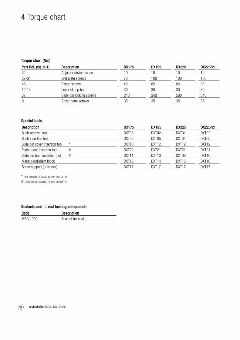
Torque chart (Nm)
Part Ref. (fig. 2-1) Description DX175 DX195 DX225 DX225/2132 Adjuster device screw 10 10 10 1027-31 End plate screws 70 100 100 10046 Piston screws 45 85 85 8512-14 Lever clamp bolt 30 30 30 3037 Slide pin locking screws 240 340 500 3409 Cover plate screws 35 35 35 35
Sealants and thread locking compounds
Code DescriptionMBG 1002 Sealant for seals
Special tools
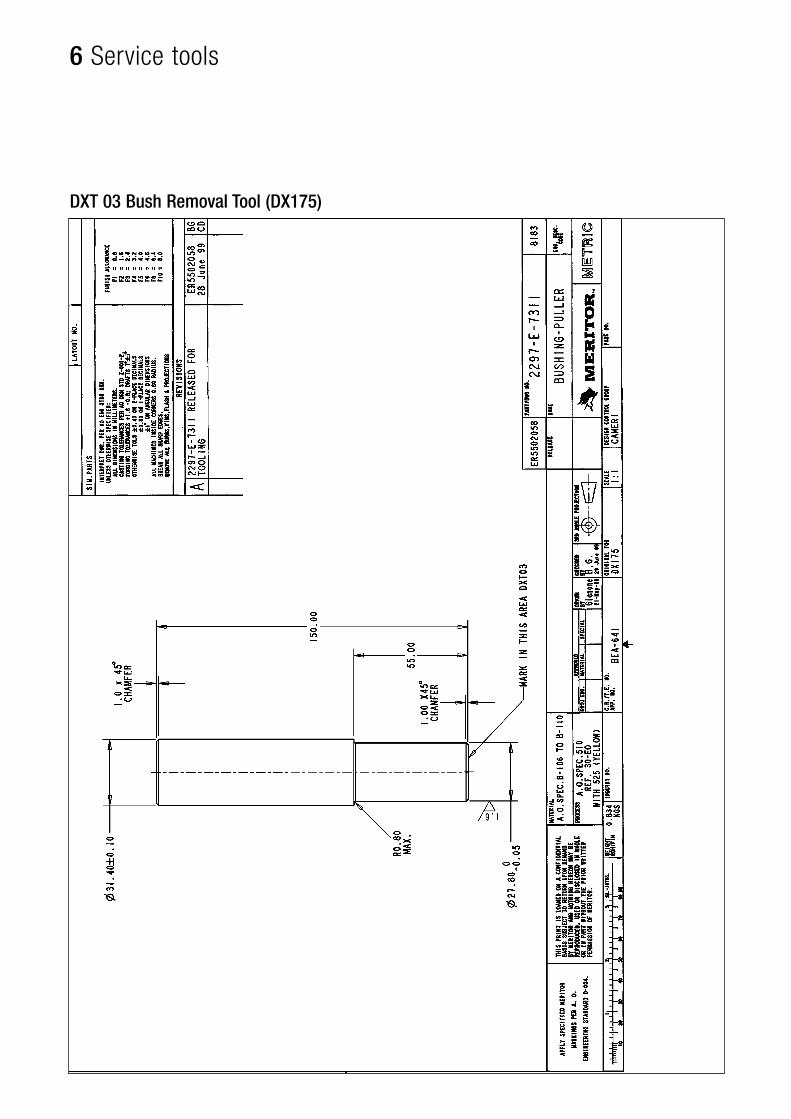
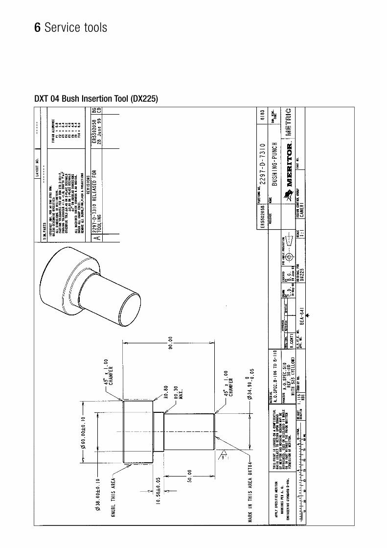
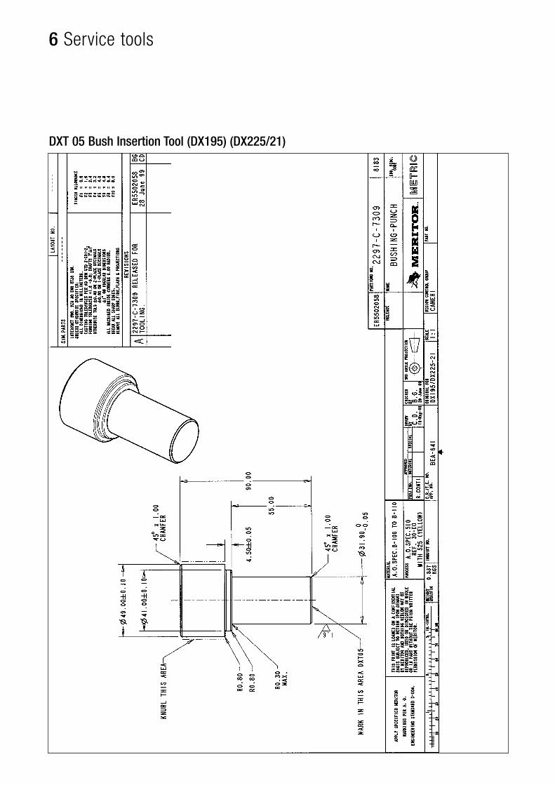
Description DX175 DX195 DX225 DX225/21Bush removal tool DXT03 DXT02 DXT01 DXT02Bush insertion tool DXT06 DXT05 DXT04 DXT05Slide pin cover insertion tool * DXT18 DXT12 DXT12 DXT12Piston boot insertion tool # DXT22 DXT21 DXT21 DXT21Slide pin boot insertion tool # DXT11 DXT10 DXT09 DXT10Metal parallelism block DXT15 DXT14 DXT13 DXT16Brake support (universal) DXT17 DXT17 DXT17 DXT17
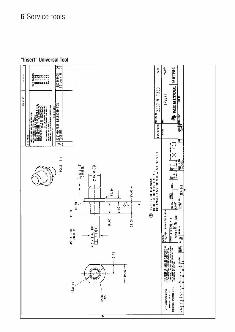
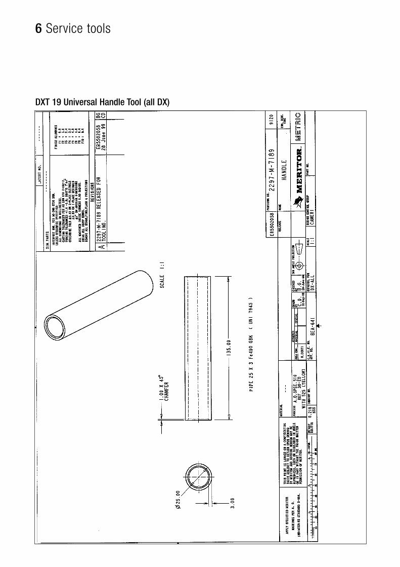
* Use straight universal handle tool DXT19
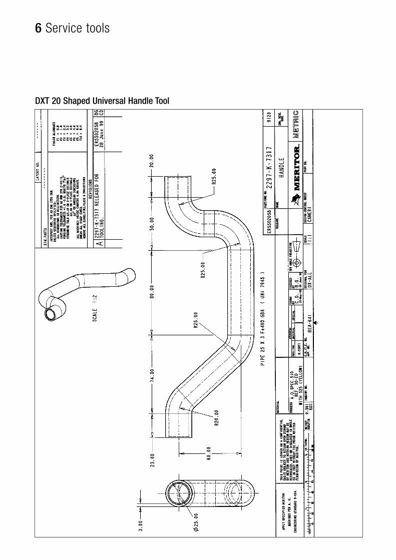
# Use shaped universal handle tool DXT20
43ArvinMeritor DX Air Disc Brake
pg.
5
Troubleshooting
44 Troubleshooting
44 ArvinMeritor DX Air Disc Brake
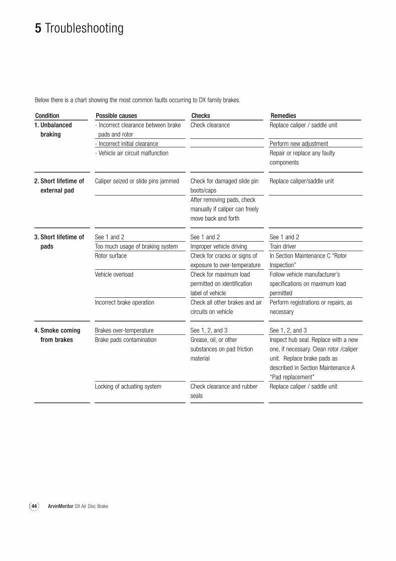
Below there is a chart showing the most common faults occurring to DX family brakes.
Condition1. Unbalanced
braking
2. Short lifetime of external pad
3. Short lifetime of pads
4. Smoke coming from brakes
Possible causes- Incorrect clearance between brake
pads and rotor- Incorrect initial clearance- Vehicle air circuit malfunction
Caliper seized or slide pins jammed
See 1 and 2Too much usage of braking systemRotor surface
Vehicle overload
Incorrect brake operation
Brakes over-temperatureBrake pads contamination
Locking of actuating system
ChecksCheck clearance
Check for damaged slide pinboots/capsAfter removing pads, checkmanually if caliper can freelymove back and forth
See 1 and 2Improper vehicle drivingCheck for cracks or signs ofexposure to over-temperatureCheck for maximum loadpermitted on identificationlabel of vehicleCheck all other brakes and aircircuits on vehicle
See 1, 2, and 3Grease, oil, or othersubstances on pad frictionmaterial
Check clearance and rubberseals
RemediesReplace caliper / saddle unit
Perform new adjustmentRepair or replace any faultycomponents
Replace caliper/saddle unit
See 1 and 2Train driverIn Section Maintenance C “RotorInspection”Follow vehicle manufacturer’sspecifications on maximum loadpermittedPerform registrations or repairs, asnecessary
See 1, 2, and 3Inspect hub seal. Replace with a newone, if necessary. Clean rotor /caliperunit. Replace brake pads asdescribed in Section Maintenance A“Pad replacement”Replace caliper / saddle unit
5 Troubleshooting
45ArvinMeritor DX Air Disc Brake
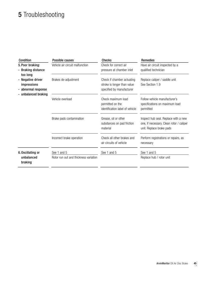
Condition5.Poor braking:- Braking distance
too long- Negative driver
impressions - abnormal response - unbalanced braking
6.Oscillating or unbalanced braking
Possible causesVehicle air circuit malfunction
Brakes de-adjustment
Vehicle overload
Brake pads contamination
Incorrect brake operation
See 1 and 5Rotor run out and thickness variation
ChecksCheck for correct airpressure at chamber inlet
Check if chamber actuatingstroke is longer than valuespecified by manufacturer
Check maximum loadpermitted on theidentification label of vehicle
Grease, oil or othersubstances on pad frictionmaterial
Check all other brakes andair circuits of vehicle
See 1 and 5
RemediesHave air circuit inspected by aqualified technician
Replace caliper / saddle unitSee Section 1.9
Follow vehicle manufacturer’sspecifications on maximum loadpermitted
Inspect hub seal. Replace with a newone, if necessary. Clean rotor / caliperunit. Replace brake pads
Perform registrations or repairs, asnecessary
See 1 and 5Replace hub / rotor unit
5 Troubleshooting

46 ArvinMeritor DX Air Disc Brake
47ArvinMeritor DX Air Disc Brake
pg.
6
Service tools
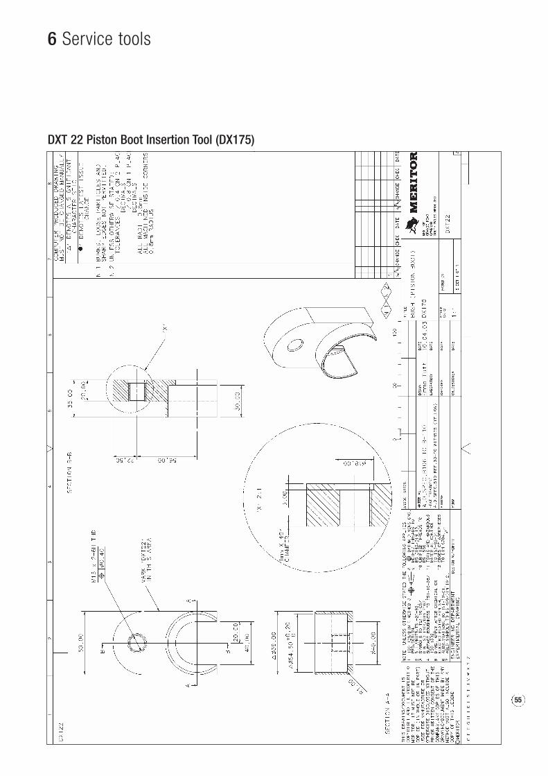
48 DXT 01 Bush Removal Tool (DX225)49 DXT 02 Bush Removal Tool (DX195) (DX225/21)50 DXT 03 Bush Removal Tool (DX175)51 DXT 04 Bush Insertion Tool (DX225)52 DXT 05 Bush Insertion Tool (DX195) (DX225/21)53 DXT 06 Bush Insertion Tool (DX175)54 DXT 21 Piston Boot Insertion Tool
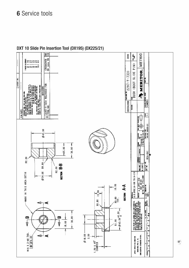
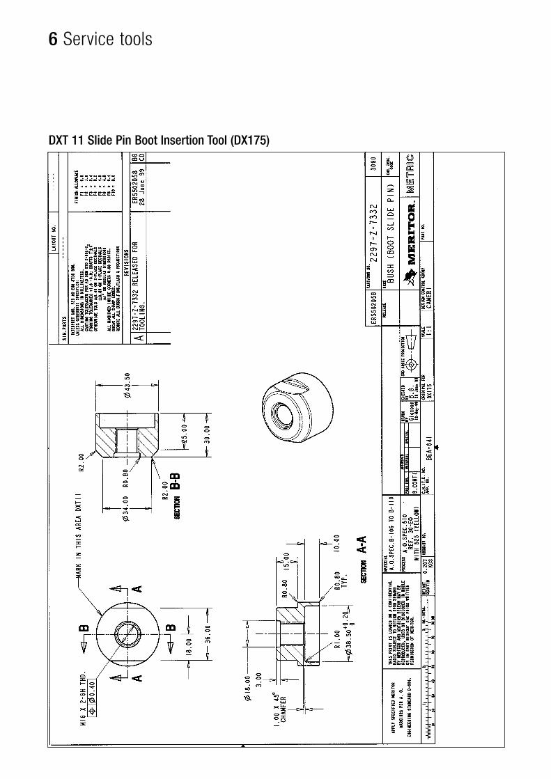
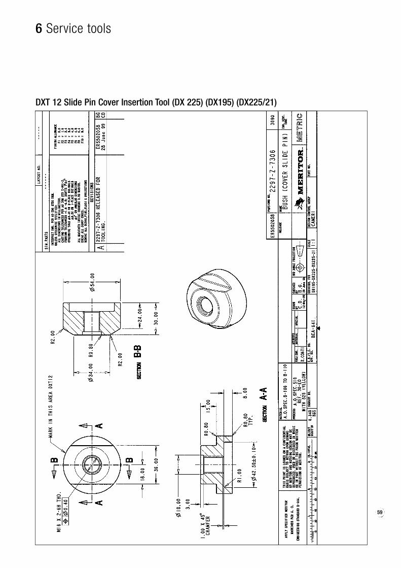
(DX225) (DX195) (DX225/21)55 DXT 22 Piston Boot Insertion Tool (DX175)56 DXT 09 Slide Pin Boot Insertion Tool (DX225)57 DXT 10 Slide Pin Insertion Tool (DX195) (DX225/21)58 DXT 11 Slide Pin Boot Insertion Tool (DX175)59 DXT 12 Slide Pin Cover Insertion Tool
(DX 225) (DX195) (DX225/21)60 DXT 13 Metal Parallelism Block (DX225)61 DXT 14 Metal Parallelism Block (DX195)62 DXT 15 Metal Parallelism Block (DX175)63 DXT 16 Metal Parallelism Block (DX225/21)64 DXT 17 Brake Support [universal) (all DX)65 DXT 18 Slide Pin Cover Insertion Tool (DX175)66 DXT 19 Universal Handle Tool (all DX)67 DXT 20 Shaped Universal Handle Tool68 “Insert” Universal Tool 69 “Round Head” Universal Tool70 “Handle Shaped” Universal 71 “Handle Straight” Universal
6 Service tools
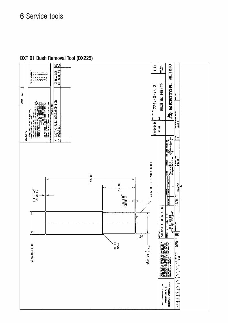
DXT 01 Bush Removal Tool (DX225)
49
6 Service tools
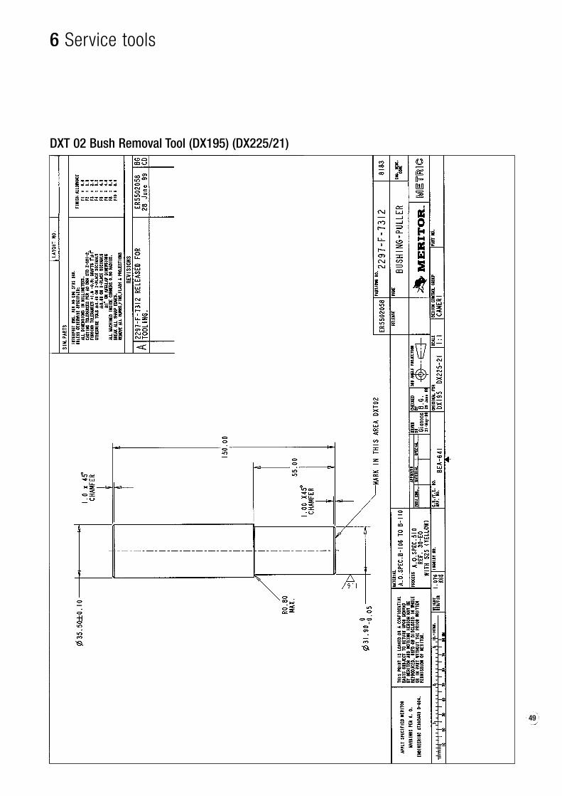
DXT 02 Bush Removal Tool (DX195) (DX225/21)

6 Service tools
DXT 03 Bush Removal Tool (DX175)

51
6 Service tools
DXT 04 Bush Insertion Tool (DX225)

6 Service tools
DXT 05 Bush Insertion Tool (DX195) (DX225/21)

53
6 Service tools
DXT 06 Bush Insertion Tool (DX175)

6 Service tools
DXT 21 Piston Boot Insertion Tool (DX225) (DX195) (DX225/21)
55
6 Service tools
DXT 22 Piston Boot Insertion Tool (DX175)

6 Service tools
DXT 09 Slide Pin Boot Insertion Tool (DX225)
57
6 Service tools
DXT 10 Slide Pin Insertion Tool (DX195) (DX225/21)
6 Service tools
DXT 11 Slide Pin Boot Insertion Tool (DX175)
59
6 Service tools
DXT 12 Slide Pin Cover Insertion Tool (DX 225) (DX195) (DX225/21)

6 Service tools
DXT 13 Metal Parallelism Block (DX225)

61
6 Service tools
DXT 14 Metal Parallelism Block (DX195)
6 Service tools
DXT 15 Metal Parallelism Block (DX175)

63
6 Service tools
DXT 16 Metal Parallelism Block (DX225/21)

6 Service tools
DXT 17 Brake Support [universal) (all DX)

65
6 Service tools
DXT 18 Slide Pin Cover Insertion Tool (DX175)

6 Service tools
DXT 19 Universal Handle Tool (all DX)

67
6 Service tools
DXT 20 Shaped Universal Handle Tool
6 Service tools
“Insert” Universal Tool
69
6 Service tools
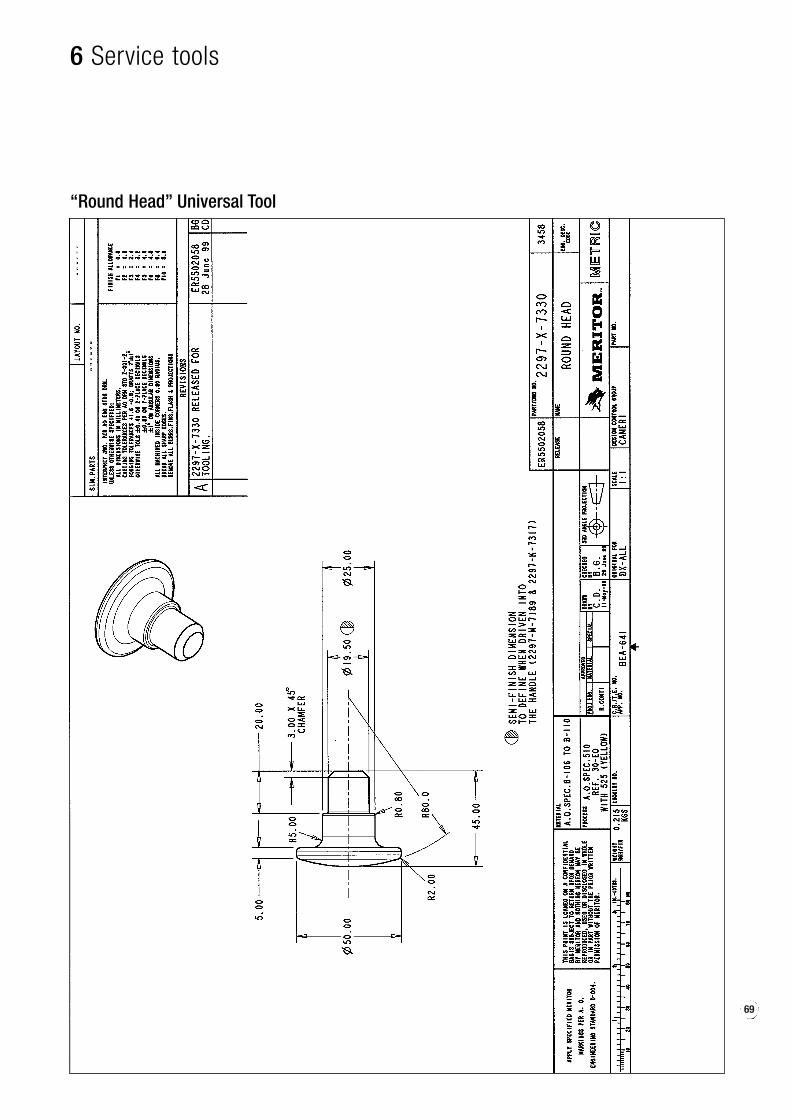
“Round Head” Universal Tool
6 Service tools
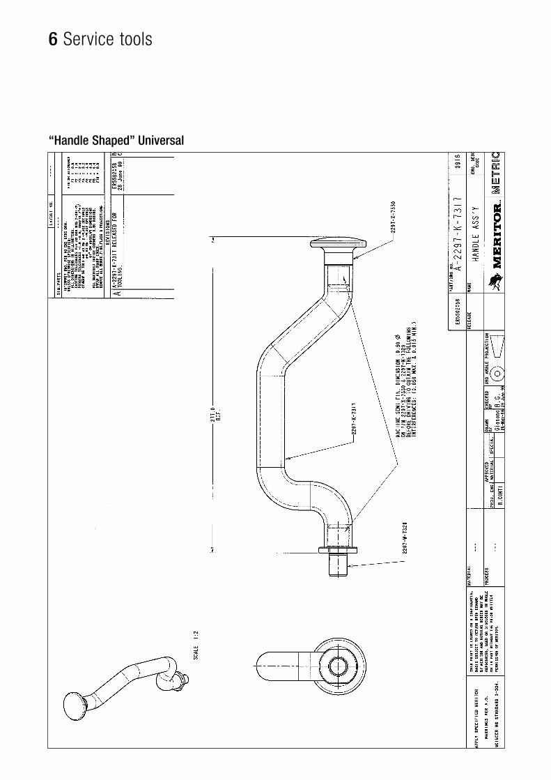
“Handle Shaped” Universal
71
6 Service tools
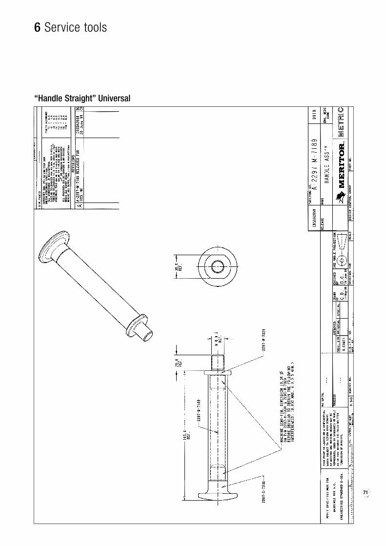
“Handle Straight” Universal

Meritor Heavy Vehicle Braking SystemsGrange Road, Cwmbran Typeset in ItalySouth Wales NP44 3XU - U.K.Tel.: +44 (0) 1633 834238 © Copyright 2002 Issued 06/2003Fax: +44 (0) 1633 834191www.arvinmeritor.com ArvinMeritor Inc. M-graph - MM1147

6 Service tools
DXT 01 Bush Removal Tool (DX225)

6 Service tools
DXT 02 Bush Removal Tool (DX195) (DX225/21)
6 Service tools
DXT 03 Bush Removal Tool (DX175)
6 Service tools
DXT 04 Bush Insertion Tool (DX225)
6 Service tools
DXT 05 Bush Insertion Tool (DX195) (DX225/21)
6 Service tools
DXT 06 Bush Insertion Tool (DX175)
6 Service tools
DXT 21 Piston Boot Insertion Tool (DX225) (DX195) (DX225/21)
6 Service tools
DXT 22 Piston Boot Insertion Tool (DX175)
6 Service tools
DXT 09 Slide Pin Boot Insertion Tool (DX225)

6 Service tools
DXT 10 Slide Pin Insertion Tool (DX195) (DX225/21)

6 Service tools
DXT 11 Slide Pin Boot Insertion Tool (DX175)

6 Service tools
DXT 12 Slide Pin Cover Insertion Tool (DX 225) (DX195) (DX225/21)
6 Service tools
DXT 13 Metal Parallelism Block (DX225)
6 Service tools
DXT 14 Metal Parallelism Block (DX195)

6 Service tools
DXT 15 Metal Parallelism Block (DX175)

6 Service tools
DXT 16 Metal Parallelism Block (DX225/21)
6 Service tools
DXT 17 Brake Support [universal) (all DX)
6 Service tools
DXT 18 Slide Pin Cover Insertion Tool (DX175)
6 Service tools
DXT 19 Universal Handle Tool (all DX)
6 Service tools
DXT 20 Shaped Universal Handle Tool

6 Service tools
DXT 12 Slide Pin Cover Insertion Tool (DX 225) (DX195) (DX225/21)

6 Service tools
DXT 18 Slide Pin Cover Insertion Tool (DX175)

![Zgbc F B Dmavfbg ©BBBªBBBBBBBBBBBBBBBBBB ]karatevolkhov.ru/Pervenstvo_MLBI_2018.pdf · ^h dx klZjr_ dx dx klZjr_ dx 8 - e_l FZevqbdb ^h dx\dexqbl_evgh ^h dx\dexqbl_evgh >_\hqdb](https://img.pdfslide.us/doc/110x75/5ec420b3644640007216892f/zgbc-f-b-dmavfbg-bbbbbbbbbbbbbbbbbbbbb-h-dx-klzjr-dx-dx-klzjr-dx-8-el.jpg)