Embed Size (px)
Citation preview
AJAN ELEKTRONIK SERVIS SANAYI TICARET LTD. STI.
MAINTENANCE MANUAL FOR AJAN PRECISION
PLASMA 260 AMPER PLASMA CUTTING MACHINES

MAINTENANCE MANUAL FOR AJAN PRECISION PLASMA CUTTING MACHINES
INDEX
ii
MAINTENANCE MANUAL FOR AJAN PRECISION PLASMA CUTTING MACHINES
INDEX
i
SECTION 1. INDEX Section name .................................................................................................................. Page number
SECTION 1. INDEX .......................................................................................................................... i
SECTION 2. TABLE OF FIGURES .............................................................................................. iv
SECTION 3. TABLES .................................................................................................................... vii
SECTION 4. COMPANY PROFILE ...............................................................................................1
SECTION 5. INSTALLATION AND ELECTROMAGNETIC COMPATIBILITY .................2
5.1. EMC INTRODUCTION .......................................................................................................... 2
5.2. INSTALLATION AND USAGE ............................................................................................. 2
5.3. ESTIMATION OF AREA ........................................................................................................ 2
5.4. MAIN POWER......................................................................................................................... 3
5.5. EQUIPOTENTIAL BONDINGS ............................................................................................. 3
SECTION 6. SAFETY .......................................................................................................................4
6.1. RECOGNIZE SAFETY INFORMATION .............................................................................. 4
6.2. FOLLOWING SAFETY INSTRUCTIONS ............................................................................ 4
6.3. DANGER, WARNING, CAUTION ........................................................................................ 4
6.4. FIRE AND EXPLOSION RISKS WHILE CUTTING ............................................................ 5
6.4.1. Prevention from Explosion ................................................................................................ 5
6.5. ELECTRIC SHOCK................................................................................................................. 6
6.5.1. Prevention from Electric Shock ......................................................................................... 6
6.6. TOXIC FUMES OCCUR WHILE CUTTING ........................................................................ 7
6.7. PLASMA ARC RAY INJURES EYES AND SKIN ............................................................... 7
6.7.1. GROUNDING SAFETY ................................................................................................... 8
6.7.2. SAFETY FOR COMPRESSED CYLINDERS ................................................................. 8
6.7.3. GAS CYLINDERS CAN EXPLODE ............................................................................... 8
6.8. NOISE DAMAGE .................................................................................................................... 9
6.9. SAFETY SIGNS AND DESCRIPTIONS .............................................................................. 10
6.10. WELDING FUMES AND GASES ...................................................................................... 12
6.10.1. FUMES AND GASES .................................................................................................. 12
6.10.2. TOXIC FUMES AND GASES ..................................................................................... 13
6.10.3. LOW-TEMPERATURE PLASMA FUMES, EXHAUST GAS PURIFICATION FOR
ORGANIC ..................................................................................................................... 13
SECTION 7. WARRANTY .............................................................................................................14
7.1. AJAN BRAND PLASMA AND OXY-FUEL CUTTING MACHINE WARRANTY
CONDITIONS ..................................................................................................................... 14
7.2. CASES CAUSING OUT OF WARRANTY.......................................................................... 15
SECTION 8. PREUSAGE ...............................................................................................................16
8.1. ATTENTIONS BEFORE STARTING CUTTING WITH PRECISION PLASMA
MACHINES ......................................................................................................................... 16
8.1.1. CONTROL OF THE CYLINDERS AND THEIR PRESSURE ..................................... 16
8.1.2. STARTING GENERATOR ............................................................................................ 16
8.1.3. STARTING CNC UNIT .................................................................................................. 16
8.1.4. CHASSIS CABLE AND CONTROL ............................................................................. 16
MAINTENANCE MANUAL FOR AJAN PRECISION PLASMA CUTTING MACHINES
INDEX
ii
8.1.5. USAGE OF CUTTING TIPS .......................................................................................... 16
8.1.6. OPERATING JET FILTER ............................................................................................ 17
8.2. ATTENTIONS BEFORE STARTING CUTTING WITH P MACHINES ........................... 18
8.2.1. CONTROL OF THE CYLINDERS AND THEIR PRESSURE ..................................... 18
8.2.2. STARTING ..................................................................................................................... 18
8.2.3. USAGE OF OXYGEN CUTTING TIPS ........................................................................ 18
SECTION 9. MAINTENANCE INSTRUCTIONS ....................................................................... 19
SECTION 10. REPLACEMENT PLANS ...................................................................................... 20
SECTION 11. MECHANICAL PARTS ......................................................................................... 25
11.1. VENTILATION UNIT ......................................................................................................... 25
11.2. CUTTING TABLE ............................................................................................................... 28
11.3. SUCTION FAN .................................................................................................................... 29
11.4. MUFFLER ............................................................................................................................ 31
11.5. JET FILTER ......................................................................................................................... 32
11.5.1. THE DESCRIPTION OF THE JET FILTER PANEL ................................................. 35
11.5.2. DUST BAG SHAKER VALVE .................................................................................... 37
11.6. PLASMA HEAD UNIT ....................................................................................................... 38
11.7. PLASMA BRIDGE UNIT ................................................................................................... 39
11.8. X AXIS GEARBOX ............................................................................................................. 41
11.9. Y AXIS GEARBOX ............................................................................................................. 42
11.10. AJAN X-Y AXIS AC SERVO MOTOR ........................................................................... 43
11.11. AJAN Z AXIS AC SERVO MOTOR ................................................................................ 44
11.12. AJAN PLASMA TORCH .................................................................................................. 45
11.12.1. AJAN PLASMA TORCH CONNECTION DIAGRAM ............................................ 47
11.13. GENERATOR .................................................................................................................... 48
11.13.1. TORCH COOLING SYSTEM .................................................................................... 49
11.14. CNC UNIT ......................................................................................................................... 50
11.15. GENERATOR CONNECTION ......................................................................................... 51
SECTION 12. CABLES ................................................................................................................... 52
12.1. INTERFACE SHEET CONNECTION CABLES ............................................................... 52
12.1.1. IHS LIMIT CABLE ...................................................................................................... 53
12.1.2. X, Y, TR, TL AXIS DRIVE CABLES ......................................................................... 54
12.1.3. GAS CONTROL CABLE ............................................................................................. 55
12.1.4. RELAY CONTROL KABLOSU .................................................................................. 56
12.1.5. GAS CONTROL AND RELAY CONTROL CABLES FUNCTIONS ....................... 57
12.1.6. HAND CONTROL CABLE ......................................................................................... 58
12.1.7. LIMIT CABLE .............................................................................................................. 59
12.1.8. RESUME CABLE ......................................................................................................... 60
12.2. DRIVE CONNECTION CABLES ....................................................................................... 61
12.2.1. MOTOR CABLE .......................................................................................................... 62
12.2.2. DRIVE POWER CABLE .............................................................................................. 64
12.3. CNC-GENERATOR CABLE CONNECTIONS ................................................................. 65
12.3.1. CURRENT-PLST/OKMO/ARC CABLE ..................................................................... 65
12.3.2. REMOTE CONTROL CABLE ..................................................................................... 66
12.3.3. ELECTRODE-NOZZLE CABLE ................................................................................. 67
12.4. Y AXIS CABLE CONNECTIONS ...................................................................................... 68
12.4.1. PLASMA TRANSMITTER CABLE ............................................................................ 68
MAINTENANCE MANUAL FOR AJAN PRECISION PLASMA CUTTING MACHINES
INDEX
iii
12.4.2. OHMIC-OHMIC IHS-F5 CABLE ................................................................................ 69
12.4.3. PLASMA VALVE CABLE .......................................................................................... 70
12.4.4. OXYGEN(R) VALVE CABLE .................................................................................... 71
12.4.5. HEAD LIMIT(R)-THC(R)-PREHEAT SENSOR(R) CABLE ..................................... 72
12.4.6. OXYGEN TRANSMITTER CABLE ........................................................................... 74
12.4.7. OXYGEN(L) VALVE CABLE .................................................................................... 75
12.4.8. HEAD LIMIT(L)-THC(L)-PREHEAT SENSOR(L) CABLE ..................................... 76
SECTION 13. AJAN PRECISION PLASMA 260AMPER SPECIFICATIONS .......................78
13.1. AJAN PLASMA TORCH SCHEMA AND CONSUMABLES .......................................... 78
13.2. AJAN PRECISION PLASMA SYSTEM CONSUMABLES LIFETIMES AND GAS
CONSUMPTIONS ............................................................................................................... 80
13.3 PRECISION PLASMA 260AMPER PLASMA AUTOMATIC GAS CONSOLE .............. 81
13.4. ALL INCLUSIVE CONTROL PANEL ............................................................................... 82
13.5. REMOTE CONTROL HARDWARE .................................................................................. 83
13.6. HEIGHT MEASUREMENT SOFTWARE AND HARDWARE WITH 1-ARC 2-SLIDING
SLEDGE 3-OHMIC CONTACT ......................................................................................... 84
13.7. AUTOMATIC CUTTING HEIGHT CORRECTION SOFTWARE RELATED TO
ELECTRODE AND NOZZLE WEAR ............................................................................... 85
13.8 PRECISION PLASMA 260AMPER GENERATOR ........................................................... 86
13.9. SYSTEM GAS REQUIREMENT ........................................................................................ 87
SECTION 14. CUTTING CHARTS ...............................................................................................88
SECTION 15. CNC UNIT AND GENERATOR CARDS ..........................................................108
SECTION 16. CONNECTION SCHEMAS .................................................................................124
16.1. PLASMA GENERATOR CIRCULATION SCHEMA ..................................................... 137
16.2. CARDS USED IN AJAN PRECISION PLASMA PLASMA CUTTING SYSTEM........ 167
SECTION 17. PRECISION PLASMA 260AMPER SPARE PARTS CHART ........................168
SECTION 18. AJAN OXYGEN- PRECISION PLASMA 260AMPER PLASMA
DESCRIPTION OF THE CNC UNIT .....................................................................................170
18.1. GUIDE FOR THE OPERATION OF THE UNIT ............................................................. 170
18.2. MENU: 0 (MAIN MENU) ................................................................................................. 173
18.3. MENU:1 ............................................................................................................................. 178
18.4. MENU:2 ............................................................................................................................. 186
18.5. OPERATION OF HAND CONTROL UNIT .................................................................... 192
18.6. G PREPARATORY AND AUXILIARY FUNCTIONS USED IN CNC ......................... 194
18.7. AUXILIARY CODES: ....................................................................................................... 195
18.8. SAMPLE PROGRAMS ..................................................................................................... 195

MAINTENANCE MANUAL FOR AJAN PRECISION PLASMA CUTTING MACHINES
TABLE OF FIGURES
iv
SECTION 2. TABLE OF FIGURES Drawing name ................................................................................................................ Page number
Figure 1. Protectors used during cutting.............................................................................................. 7
Figure 2. General replacement plan ................................................................................................... 20
Figure 3. 3000x12000 mm plasma machine with jet filter replacement plan ................................... 21
Figure 4. 3000x6000 mm plasma machine with jet filter replacement plan ..................................... 22
Figure 5. 3000x12000 mm plasma machine without jet filter replacement plan .............................. 22
Figure 6. 2000x6000 mm plasma machine without jet filter replacement plan ................................ 23
Figure 7. 2000x6000 mm plasma machine with jet filter replacement plan ..................................... 23
Figure 8. 3000x6000 mm plasma machine without jet filter replacement plan ................................ 24
Figure 9. 3000 mm first block ventilation system ............................................................................. 25
Figure 10. 3000 mm first block ventilation unit installation drawing ............................................... 26
Figure 11. 3000 mm first block cover opening/closing handle system installation drawing ............ 27
Figure 12. 1500 mm cutting table installation drawing ..................................................................... 28
Figure 13. Suction fan ....................................................................................................................... 29
Figure 14. Suction fan installation drawing ...................................................................................... 30
Figure 15. Muffler ............................................................................................................................. 31
Figure 16. Jet filter ............................................................................................................................ 32
Figure 17. Total area of the cartridges used in the jet filter .............................................................. 34
Figure 18. Jet filter panel ................................................................................................................... 35
Figure 19. Dust bag shaker valve spare part list ................................................................................ 37
Figure 20. Plasma head installation drawing ..................................................................................... 38
Figure 21. Plasma bridge installation drawing .................................................................................. 39
Figure 22. Plasma bridge unit installation drawing ........................................................................... 40
Figure 23. X axis gearbox installation drawing................................................................................. 41
Figure 24. Y axis gearbox installation drawing................................................................................. 42
Figure 25. Ajan X-Y axis AC servo motor installation drawing ....................................................... 43
Figure 26. Ajan Z axis AC servo motor installation drawing ........................................................... 44
Figure 27. Ajan plasma torch installation drawing ........................................................................... 45
Figure 28. Ajan plasma torch connection diagram ............................................................................ 47
Figure 29. Generator .......................................................................................................................... 48
Figure 30. Torch cooling liquid drum warning label ........................................................................ 49
Figure 31. CNC unit .......................................................................................................................... 50
Figure 32. Generator connection diagram ......................................................................................... 51
Figure 33. Interface sheet connection cables ..................................................................................... 52
Figure 34. Drive................................................................................................................................. 61
Figure 35. Ajan torch schema ............................................................................................................ 78
Figure 36. Ajan precısıon plasma 260 amper Electrode and Nozzle required life time chart ........... 80
Figure 37. Ajan precısıon plasma 130 amper Electrode and Nozzle required life time chart ........... 80
Figure 38. Other conventional automatic gas consoles ..................................................................... 81
Figure 39. Ajan automatic gas console .............................................................................................. 81
Figure 40. New conception Ajan all inclusive plasma cutting system .............................................. 82
Figure 41. Schema for required connection between units on Ajan all inclusive plasma system ..... 83
Figure 42. Ajan initial height control systems................................................................................... 84
Figure 43. Ohmic system comparison ............................................................................................... 84
Figure 44. Torch height control systems comparison ....................................................................... 85
Figure 45. precısıon plasma 260 Amper generator ........................................................................... 86
Figure 46. Arc transfer card............................................................................................................. 108
Figure 47. Firing box card ............................................................................................................... 109

MAINTENANCE MANUAL FOR AJAN PRECISION PLASMA CUTTING MACHINES
TABLE OF FIGURES
v
Figure 48. Flow card ........................................................................................................................ 110
Figure 49. IGBT driver card ............................................................................................................ 111
Figure 50. IHS limit card ................................................................................................................. 112
Figure 51. Interface sheet ................................................................................................................ 113
Figure 52. precısıon plasma generator control card ........................................................................ 114
Figure 53. precısıon plasma Generator control card........................................................................ 115
Figure 54. Condenser card ............................................................................................................... 116
Figure 55. Logic control card .......................................................................................................... 117
Figure 56. Logic control card .......................................................................................................... 118
Figure 57. Front panel card.............................................................................................................. 119
Figure 58. Power card ...................................................................................................................... 120
Figure 59. Resistance card ............................................................................................................... 121
Figure 60. Start circuit ..................................................................................................................... 122
Figure 61. Varistor card ................................................................................................................... 123
Figure 62. Plasma plate ................................................................................................................... 124
Figure 63. Plasma plate hose gas connection schema ..................................................................... 125
Figure 64. Oxygen plate .................................................................................................................. 126
Figure 65. Oxy-Plasma hose gas connection schema ...................................................................... 127
Figure 66. Plasma plate card connection schema ............................................................................ 128
Figure 67. precısıon plasma automatic gas console plasma plate connection schema .................... 129
Figure 68. precısıon plasma single head oxygen plate connection schema..................................... 130
Figure 69. precısıon plasma automatic gas console double head plate connection schema ............ 131
Figure 70. precısıon plasma double head oxygen plate connection schema ................................... 132
Figure 71. precısıon plasma automatic gas console double oxygen plate connection schema ....... 133
Figure 72. precısıon plasma four head oxygen plate connection schema ....................................... 134
Figure 73. precısıon plasma triple head plate connection schema ................................................. 135
Figure 74. Interface connection schema .......................................................................................... 136
Figure 75. Plasma generator circulation schema ............................................................................. 137
Figure 76. precısıon plasma 260A generator connection schema .................................................. 138
Figure 77. precısıon plasma 260A+oxygen cutting CNC connection schema ................................ 139
Figure 78. precısıon plasma 260A+double head oxygen cutting CNC connection schema ........... 140
Figure 79. Arc voltage divider connection schema ........................................................................ 141
Figure 80. Arc voltage control system connection schema ............................................................. 142
Figure 81. Axis control system connection schema ........................................................................ 143
Figure 82. precısıon plasma generator control card connection schema ......................................... 144
Figure 83. Flow LED control system connection schema ............................................................... 145
Figure 84. Plasma start control card connection schema ................................................................ 146
Figure 85. Jet filter system connection schema ............................................................................... 147
Figure 86. precısıon plasma 260A main power connection schema ............................................... 148
Figure 87. precısıon plasma oxygen+marking control card connection schema ............................. 149
Figure 88. IGBT drive system connection schema ......................................................................... 150
Figure 89. precısıon plasma double head control card connection schema..................................... 151
Figure 90. precısıon plasma double head plate connection schema ................................................ 152
Figure 91. Logic card input-output control connection schema ...................................................... 153
Figure 92. Plasma control connection schema ................................................................................ 154
Figure 93. precısıon plasma power control connection schema ...................................................... 155
Figure 94. CNC power system connection schema ......................................................................... 156
Figure 95. Remote control start-stop system connection schema ................................................... 157
Figure 96. Servo motor drive system connection schema ............................................................... 158
Figure 97. THC unit system connection schema ............................................................................. 159

MAINTENANCE MANUAL FOR AJAN PRECISION PLASMA CUTTING MACHINES
TABLE OF FIGURES
vi
Figure 98. Logic card input-output controls schema ....................................................................... 160
Figure 99. Generator fan, CNC connection schema ........................................................................ 161
Figure 100. Generator fan, CNC connection schema ...................................................................... 162
Figure 101. Interface DSUB output sockets connection schema .................................................... 163
Figure 102. precısıon plasma block connection output connection schema ................................... 164
Figure 103. precısıon plasma 260A connection schema ................................................................. 165
Figure 104. precısıon plasma CNC plasma main transformer ........................................................ 166
Figure 105. Hand control unit label ................................................................................................. 192
MAINTENANCE MANUAL FOR AJAN PRECISION PLASMA CUTTING MACHINES
TABLES
vii
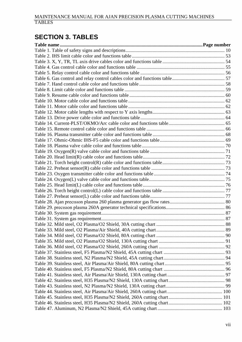
SECTION 3. TABLES Table name ..................................................................................................................... Page number
Table 1. Table of safety signs and descriptions ................................................................................. 10
Table 2. IHS limit cable color and functions table ............................................................................ 53
Table 3. X, Y, TR, TL axis drive cables color and functions table ................................................... 54
Table 4. Gas control cable color and functions table ........................................................................ 55
Table 5. Relay control cable color and functions table ..................................................................... 56
Table 6. Gas control and relay control cables color and functions table ........................................... 57
Table 7. Hand control cable color and functions table ...................................................................... 58
Table 8. Limit cable color and functions table .................................................................................. 59
Table 9. Resume cable color and functions table .............................................................................. 60
Table 10. Motor cable color and functions table ............................................................................... 62
Table 11. Motor cable color and functions table ............................................................................... 62
Table 12. Motor cable lengths with respect to Y axis lengths ........................................................... 63
Table 13. Drive power cable color and functions table ..................................................................... 64
Table 14. Current-PLST/OKMO/Arc cable color and functions table .............................................. 65
Table 15. Remote control cable color and functions table ................................................................ 66
Table 16. Plasma transmitter cable color and functions table ........................................................... 68
Table 17. Ohmic-Ohmic IHS-F5 cable color and functions table ..................................................... 69
Table 18. Plasma valve cable color and functions table .................................................................... 70
Table 19. Oxygen(R) valve cable color and functions table ............................................................. 71
Table 20. Head limit(R) cable color and functions table ................................................................... 72
Table 21. Torch height control(R) cable color and functions table ................................................... 73
Table 22. Preheat sensor(R) cable color and functions table ............................................................ 73
Table 23. Oxygen transmitter cable color and functions table .......................................................... 74
Table 24. Oxygen(L) valve cable color and functions table.............................................................. 75
Table 25. Head limit(L) cable color and functions table ................................................................... 76
Table 26. Torch height control(L) cable color and functions table ................................................... 77
Table 27. Preheat sensor(L) cable color and functions table ............................................................. 77
Table 28. Ajan precısıon plasma 260 plasma generator gas flow rates ............................................. 80
Table 29. precısıon plasma 260A generator technical specifications ................................................ 86
Table 30. System gas requirement ..................................................................................................... 87
Table 31. System gas requirement ..................................................................................................... 87
Table 32. Mild steel, O2 Plasma/O2 Shield, 30A cutting chart ........................................................ 88
Table 33. Mild steel, O2 Plasma/Air Shield, 40A cutting chart ........................................................ 89
Table 34. Mild steel, O2 Plasma/O2 Shield, 80A cutting chart ........................................................ 90
Table 35. Mild steel, O2 Plasma/O2 Shield, 130A cutting chart ...................................................... 91
Table 36. Mild steel, O2 Plasma/O2 Shield, 260A cutting chart ...................................................... 92
Table 37. Stainless steel, F5 Plasma/N2 Shield, 45A cutting chart .................................................. 93
Table 38. Stainless steel, N2 Plasma/N2 Shield, 45A cutting chart .................................................. 94
Table 39. Stainless steel, Air Plasma/Air Shield, 80A cutting chart ................................................. 95
Table 40. Stainless steel, F5 Plasma/N2 Shield, 80A cutting chart .................................................. 96
Table 41. Stainless steel, Air Plasma/Air Shield, 130A cutting chart ............................................... 97
Table 42. Stainless steel, H35 Plasma/N2 Shield, 130A cutting chart .............................................. 98
Table 43. Stainless steel, N2 Plasma/N2 Shield, 130A cutting chart ................................................ 99
Table 44. Stainless steel, Air Plasma/Air Shield, 260A cutting chart ............................................. 100
Table 45. Stainless steel, H35 Plasma/N2 Shield, 260A cutting chart ............................................ 101
Table 46. Stainless steel, H35 Plasma/N2 Shield, 260A cutting chart ............................................ 102
Table 47. Aluminum, N2 Plasma/N2 Shield, 45A cutting chart ..................................................... 103
MAINTENANCE MANUAL FOR AJAN PRECISION PLASMA CUTTING MACHINES
TABLES
viii
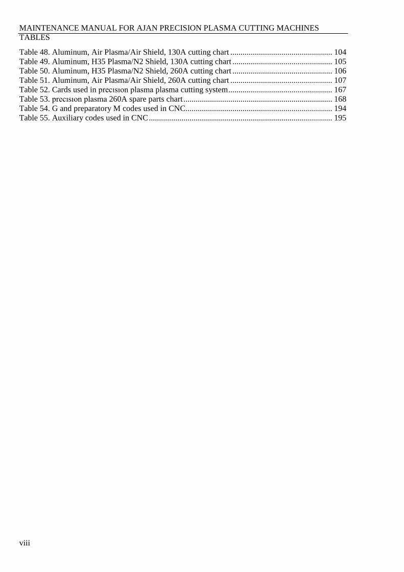
Table 48. Aluminum, Air Plasma/Air Shield, 130A cutting chart .................................................. 104
Table 49. Aluminum, H35 Plasma/N2 Shield, 130A cutting chart ................................................. 105
Table 50. Aluminum, H35 Plasma/N2 Shield, 260A cutting chart ................................................. 106
Table 51. Aluminum, Air Plasma/Air Shield, 260A cutting chart .................................................. 107
Table 52. Cards used in precısıon plasma plasma cutting system ................................................... 167
Table 53. precısıon plasma 260A spare parts chart ......................................................................... 168
Table 54. G and preparatory M codes used in CNC........................................................................ 194
Table 55. Auxiliary codes used in CNC .......................................................................................... 195
MAINTENANCE MANUAL FOR AJAN PRECISION PLASMA CUTTING MACHINES
COMPANY PROFILE
1
SECTION 4. COMPANY PROFILE
Manufacturer since 1973 Ajan Elektronik, established in 1973, started its life by manufacturing uninterruptable power supply
systems. The firm decided to manufacture Electrical Discharge Machines and released the first
machine in 1975 to the market.
In early years due to the conditions of the day, the company manufactured hydraulic machines, but
today the company switched to AC servo controlled machines.
Ajan Elektronik started to work on CNC projects in 1988–89, and manufactured the first CNC
Erosion Machine in 2000. Continuing working on this subject in R&D department, the company
developed and manufactured CNC Milling Machines, CNC Lathes, CNC Plasma and Oxy-Fuel
Cutting Machines, CNC Drilling Machines and CNC Laser Cutting Machines.
All the CNC control units and software, servo drives and AC servo motors of the manufactured
machines are completely own production of the company.
Ajan Elektronik provides AjanCAD Ajan Drawing software free of charge with the manufactured
machines to the customers.
The company supplies 85% of the raw and intermediary materials used in manufacturing of the
machines, whose design is completely done by itself, from the domestic market. Hence, the
company supports the economy of the country.
In addition, Ajan Elektronik began many new projects according to the customer demands.
As a result of giving importance to quality, the company has won ISO 9001:2000 Quality
Certificate on June 24th 2003.
AJAN ELEKTRONIK SERVIS SAN. VE TIC. LTD. STI.
Address : Merkez Mah. 67. Sk. No:3 Sasali-Cigli / Izmir / TURKEY
Web : www.ajancnc.com
e-mail : [email protected]
Tel : +902323273480
Fax : +902323273430
MAINTENANCE MANUAL FOR AJAN PRECISION PLASMA CUTTING MACHINES
INSTALLATION AND ELECTROMAGNETIC COMPATIBILITY
2
SECTION 5. INSTALLATION AND ELECTROMAGNETIC COMPATIBILITY
5.1. EMC INTRODUCTION
Ajan Plasma Machine with CE mark is built compliance with machinery directive 98/37/EC, low
voltage directive 73/23/EEC and EMC directive 89/336/EEC.
CNC PLASMA AND
OXY-FUEL CUTTING
MACHINES
TS EN 292–1/292–2
TS 10316 EN 60204–1
TS EN 50370–2
TS EN 61000–6–2
TS EN 1050
TS EN 61310–1/2
TS EN 61496–1
TS EN 1037
TS EN 953
TS EN 563
TS EN ISO 9001:2000
5.2. INSTALLATION AND USAGE
The user is responsible for the specified directives while using Ajan brand plasma, oxygen
machines and equipments. During solving any electromagnetic problem, at first the technical
documents supplied by the manufacturer firm then technical assistance of the firm must be applied.
In some cases, although the defects can be simply solved, because of unauthorized actions may
cause the solution hard.
5.3. ESTIMATION OF AREA
The user should specify the area’s situation by taking into account the following electromagnetic
influence risks before the installation.
Supply cables, control cables, telephone cables near the machine’s control units
Radio and television transmitters and receivers
Computer and other control units
Safety critical equipments
The health devices like pacemaker and hearing equipments and the people using these
Calibration and measurement devices
The indicated influences differ depending on the building structure and other activities in the
surrounding area. These may extend beyond the surrounding area.
MAINTENANCE MANUAL FOR AJAN PRECISION PLASMA CUTTING MACHINES
INSTALLATION AND ELECTROMAGNETIC COMPATIBILITY
3
5.4. MAIN POWER
The grounding must take place at the main power.
The main power of the machine must be connected in accordance to the manufacturer’s directives.
If any interference or undulation at the current occurs, a filter (regulator) can be added to the main
power or the supply cable can be shielded. In addition, it is advised that the electrical supply cable
must be in length of maximum 5 meters and the temperature of the ambiance must not extend 40ºC.
Under the case of that the allowed temperature is extended, the cutting current should be reduced. It
is suitable for the cables to be put into a metal conduit in order to prevent having hazards.
5.5. EQUIPOTENTIAL BONDINGS
The machine produces high voltage during firing. The operator must not touch the cutting
equipments (torch, electrodes, etc.) during firing in order to prevent an electric shock. In addition to
this, unearthed work piece and all equipments connected to the machine includes high voltage
during cutting and this causes critical risk. So grounding of the work piece and all equipments must
be supplied.
MAINTENANCE MANUAL FOR AJAN PRECISION PLASMA CUTTING MACHINES
SAFETY
4
SECTION 6. SAFETY
6.1. RECOGNIZE SAFETY INFORMATION
The symbols shown in this section are used at areas where potential risks may
occur. Understand the potential personal injury and follow the instructions to prevent the hazard
when you see a safety symbol in this manual or on your machine.
6.2. FOLLOWING SAFETY INSTRUCTIONS
Read all safety messages and warnings in this manual and safety labels on your machine.
Keep the safety labels on your machine seen. For that, use cleaning materials that does not
damage the labels while cleaning. Replace the damaged and missing labels with a new one.
Learn how to operate the machine and its controls. Do not allow unauthorized or ignorant
person to operate the machine.
Keep the machine in suitable working conditions. Unauthorized modifications on the machine
may affect wrongly the safety and operation of the machine.
6.3. DANGER, WARNING, CAUTION
DANGER word identifies the most serious hazards like “ELECTRIC SHOCK CAN KILL”.
WARNING symbol follows the instructions that may cause injury or death when they are not
correctly obeyed. “OXYGEN CUTTING CAN CAUSE EXPLOSION”
A CAUTION safety message identifies the instructions that may cause damage to the machine
or equipment if it is not correctly followed. “COOLING PUMP WILL BE DAMAGED IF IT IS
RUN WITH WATER ONLY”
MAINTENANCE MANUAL FOR AJAN PRECISION PLASMA CUTTING MACHINES
SAFETY
5
6.4. FIRE AND EXPLOSION RISKS WHILE CUTTING
Prevention from Fire
Keep safety of the cutting area before starting to cut and place a fire extinguisher near you.
Do not place any flammable or explosive materials within 2 meters of the cutting area.
Do not handle the hot cut material or wait until it cools.
Do not cut containers including flammable or explosive material, pressurized gases or toxic
materials.
Flammable atmosphere should be removed from the area before cutting.
WARNING
Explosion Hazard
Argon-Hydrogen
Hydrogen is a flammable gas that may cause an explosion hazard. Keep cylinders and hoses
containing Hydrogen away from the flame. Keep torch hoses away from flame and spark during
Hydrogen-Argon plasma cutting.
6.4.1. Prevention from Explosion
If there is possibility of that explosive smokes or vapors exist in the area, do not use plasma
system.
Do not cut containers including pressurized cylinders, hoses or any closed containers.

MAINTENANCE MANUAL FOR AJAN PRECISION PLASMA CUTTING MACHINES
SAFETY
6
6.5. ELECTRIC SHOCK
It can cause fatal shocks or severe burns to touch parts containing electricity.
The plasma systems work in principle of completing electric current between the cutting
torch and the work piece. So since work piece and anything touching the work piece area
part of this electrical circuit, do not touch the torch body while plasma system is
operated.
6.5.1. Prevention from Electric Shock
All Ajan plasma systems work with open circuit 300 V direct current high voltage principle.
Follow the instructions indicated below for safety:
Wear insulated gloves, boots, and dry clothes.
Do not contact to wet any surface while operating the plasma system.
Prevent physical contact from the ground or any material in connection with the ground.
For that, you can use dry insulating mat or cover. If the working area is damp, be
careful.
Inspect frequently the durability of main supply cables. Replace the damaged cables
with a new one. Bare wiring can cause kill.
Disconnect the main power before cleaning or changing the parts of torch unit.
Do not pick up the work piece or cut materials during cutting.
Before acting on the electric unit, disconnect electrical connections and wait for
minimum 5 minutes to let the capacitors discharge.
Connect grounding conductor when making input connections.
Ajan plasma systems are designed for only specific Ajan torches. It causes danger to use
other torches.
MAINTENANCE MANUAL FOR AJAN PRECISION PLASMA CUTTING MACHINES
SAFETY
7
6.6. TOXIC FUMES OCCUR WHILE CUTTING
Plasma and oxygen cutting can cause gases that can reduce oxygen and cause injury or death.
Ventilate the cutting area well and remove the occurring gases from the atmosphere.
Do not make cutting near places where cleaning processes are done.
Use a ventilation system while cutting materials containing Lead, Cadmium, or Beryllium.
Otherwise, since poisonous gases and fumes occur while cutting, it can cause injury or
death.
Do not cut the containers containing toxic materials. Empty and clean properly.
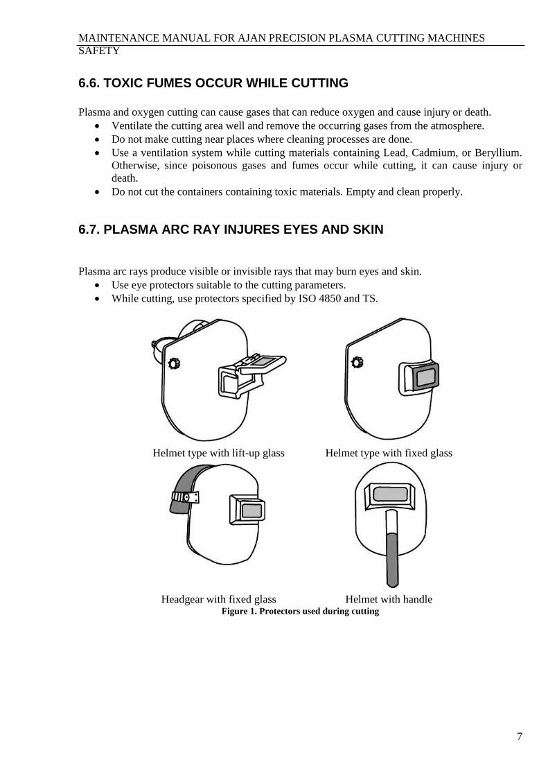
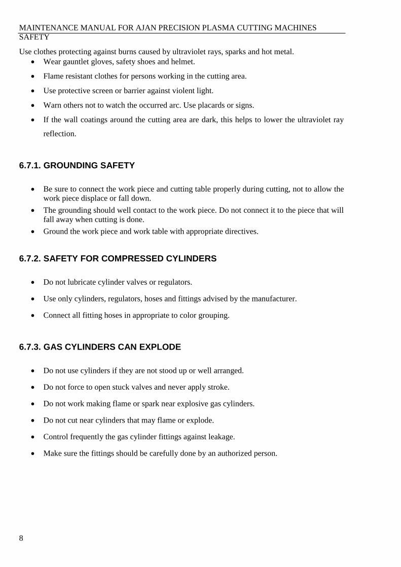
6.7. PLASMA ARC RAY INJURES EYES AND SKIN
Plasma arc rays produce visible or invisible rays that may burn eyes and skin.
Use eye protectors suitable to the cutting parameters.
While cutting, use protectors specified by ISO 4850 and TS.
Helmet type with lift-up glass Helmet type with fixed glass
Headgear with fixed glass Helmet with handle
Figure 1. Protectors used during cutting
MAINTENANCE MANUAL FOR AJAN PRECISION PLASMA CUTTING MACHINES
SAFETY
8
Use clothes protecting against burns caused by ultraviolet rays, sparks and hot metal.
Wear gauntlet gloves, safety shoes and helmet.
Flame resistant clothes for persons working in the cutting area.
Use protective screen or barrier against violent light.
Warn others not to watch the occurred arc. Use placards or signs.
If the wall coatings around the cutting area are dark, this helps to lower the ultraviolet ray
reflection.
6.7.1. GROUNDING SAFETY
Be sure to connect the work piece and cutting table properly during cutting, not to allow the
work piece displace or fall down.
The grounding should well contact to the work piece. Do not connect it to the piece that will
fall away when cutting is done.
Ground the work piece and work table with appropriate directives.
6.7.2. SAFETY FOR COMPRESSED CYLINDERS
Do not lubricate cylinder valves or regulators.
Use only cylinders, regulators, hoses and fittings advised by the manufacturer.
Connect all fitting hoses in appropriate to color grouping.
6.7.3. GAS CYLINDERS CAN EXPLODE
Do not use cylinders if they are not stood up or well arranged.
Do not force to open stuck valves and never apply stroke.
Do not work making flame or spark near explosive gas cylinders.
Do not cut near cylinders that may flame or explode.
Control frequently the gas cylinder fittings against leakage.
Make sure the fittings should be carefully done by an authorized person.

MAINTENANCE MANUAL FOR AJAN PRECISION PLASMA CUTTING MACHINES
SAFETY
9
6.8. NOISE DAMAGE
There is a hearing loss hazard during prolonged cutting and piece removal processes applying
stroke.
Use ear bung during plasma cutting.
Identify the noise hazard in the working area of plasma machine with warning signs.
MAINTENANCE MANUAL FOR AJAN PRECISION PLASMA CUTTING MACHINES
SAFETY
10
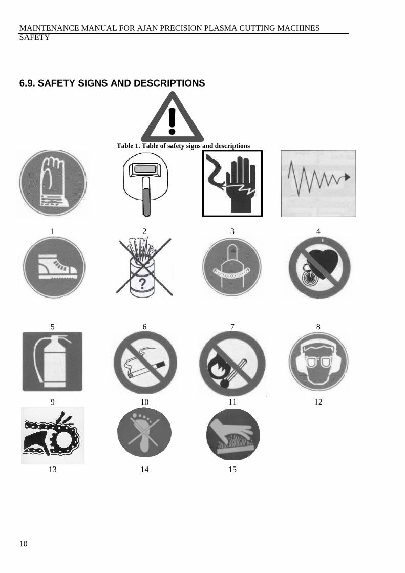
6.9. SAFETY SIGNS AND DESCRIPTIONS
Table 1. Table of safety signs and descriptions
1 2 3 4
5 6 7 8
9 10 11 12
13 14 15
MAINTENANCE MANUAL FOR AJAN PRECISION PLASMA CUTTING MACHINES
SAFETY
11
1. Use gauntlet and dry gloves for protection from hot metals, spark, dross and electric shocks.
2. Use protective helmets against dross and ultraviolet rays.
3. Do not touch bare cables against electric arcs.
4. There is ultraviolet ray hazard, follow the directives.
5. Wear dry, well-built, safety shoes.
6. Do not cut closed containers that contain flammable, explosive, or unknown materials.
7. Keep pressurized gas cylinders upright and protective caps in place over valve when the
cylinders are not in use.
8. Magnetic fields caused by the high current may injure the operands using pacemaker or
having heart diseases.
9. Keep a fire extinguisher nearby.
10. There may be flammable and explosive gases while machine is operating. To avoid this, do
not smoke near the machine and gas cylinders.
11. There may be flammable and explosive gases while machine is operating. To avoid this, do
not keep flame available near the machine and gas cylinders.
12. Plasma cutting produces noise that may cause hearing hazards. Use approved ear protection
during cutting.
13. Do not insert any material or your organs into the moving mechanisms that may obstruct the
movement.
14. Do not step onto or do not load onto places where may obstruct machine’s operation.
15. Do not make contact to hot metals.

MAINTENANCE MANUAL FOR AJAN PRECISION PLASMA CUTTING MACHINES
SAFETY
12
6.10. WELDING FUMES AND GASES
Welding fumes are an unavoidable by-product of the welding and cutting process. All these
processes generate fumes, only the type and amount vary from process to process. It consists of
particulate fume, the part you can see, and gaseous fume, the part you cannot see, but can
sometimes smell.
Exposure of welders to welding fumes depends on many factors: the most important of which is
actual type of welding is being done.
For example, FCAW, MMA, MIG, thermic lancing and plasma cutting tend to produce the highest
amounts of most particulate fumes, while TIG, plasma welding, oxy-fuel welding, laser welding,
laser cutting and submerged arc normally give very little.
TIG, plasma welding, MIG, laser cutting and welding tend to produce the most gaseous fumes
while MMA, plasma cutting and FCAW normally produce very little.
The potential effect of exposure to welding or cutting fumes depends on the composition of the
fumes.
The health effects of exposure to fumes include irritation of the upper respiratory tract (nose and
throat), tightness in the chest, wheezing, metal fume fever, lung damage, bronchitis or pneumonia,
possibly even cancer or emphysema.
Possible control measures include doing things such as changing or modifying the process, or the
way the job is done.
6.10.1. FUMES AND GASES
The nature of fume depends upon the metal being cut and upon any coating. Cutting of stainless
steel is potentially the most hazardous as the fumes will contain chromium and nickel. Copper and
its alloys are also commonly cut and can also produce a significant fume hazard. The risks from
fumes should be assessed in accordance with HSE Guidance Note EH54 Assessments of exposure to
fume from welding and allied processes.
Oxides of nitrogen are formed during plasma cutting and could accumulate in areas of poor
ventilation. These are likely to be most significant during plasma cutting where air or nitrogen is
used as the plasma gas. Ozone is most likely to be formed during cutting of aluminum or stainless
steel.
Where inert gases are used they may accumulate in contained spaces causing an asphyxiation risk.
This is most likely to occur when the gas is significantly heavier than air e.g. argon/nitrogen
mixtures.
In poorly ventilated areas, flammable gases may also produce a risk.
Gases, particularly oxides of nitrogen, are a more significant hazard at hand-held cutting than at
mechanized cutting as the operator is in close proximity to the torch.
MAINTENANCE MANUAL FOR AJAN PRECISION PLASMA CUTTING MACHINES
SAFETY
13
6.10.2. TOXIC FUMES AND GASES
Plasma arc cutting can produce toxic fumes and gases that deplete oxygen and cause serious injury.
Keep the cutting area well ventilated or use an approved air-supplied respirator.
Do not cut in locations near degreasing, cleaning or spraying operations. The vapors from
certain chlorinated solvents decompose to form phosgene gas when exposed to ultraviolet
radiation.
6.10.3. LOW-TEMPERATURE PLASMA FUMES, EXHAUST GAS PURIFICATION FOR ORGANIC
On principle, the purification device uses corona current and high power pulse discharge principle,
so that the air around the plate becomes a low-temperature plasma.
Plasma with many high-energy (OH-, O2-, H+, O3) ions are surrounding the plate, with energy of
the plasma can interrupt a variety of organic molecules of gas between the key elements so that the
decomposition of harmful gases to the fumes, formaldehyde, xylene, sulfur dioxide, ammonia
nitrogen oxides and other harmful gases and odor generated degradation and oxidation, deal with
organic material and degradation of smell effectively. In addition the purification equipment
compared with electrostatic precipitator, low power consumption, more efficient purification, and
so on.

MAINTENANCE MANUAL FOR AJAN PRECISION PLASMA CUTTING MACHINES
WARRANTY
14
SECTION 7. WARRANTY
Ajan Kesme Makinalari San. ve Tic. Ltd. Sti. supplies mechanical and electronic units and all
equipments of your machine completely depending on the made agreements. The installation, first
operation of the machine and the education will be supplied by the manufacturer firm. Ajan Plasma
and Oxygen Cutting Machine mechanical units, electronic units, software and torch are
manufactured under Ajan brand. Ajan Ltd. warrants the machines under all these conditions.
7.1. AJAN BRAND PLASMA AND OXY-FUEL CUTTING MACHINE WARRANTY CONDITIONS
1- The warranty period is 2 (two) years after the machine delivery.
2- All the parts of the machine are under our company’s guarantee.
3- Under the case when the machine has been broken down in the guarantee period, the
maintenance period is added to the warranty period. The maintenance period is 15 days
excluding the transportation under the case when the machine fault is overcome by the
manufacturer factory.
4- The approved technical staff can interfere to the fault on the machine in 48 hours after the
customer informs the manufacturer.
5- The faults, determined by the technical staff, caused by the design and production are
overcome free of charge.
6- In cases when the machine fault is out of warranty, the applied service fare is €80.00+VAT
for the year 2009. The prices of the spare part to be replaced will be sent by ourselves. The
spare part prices are valid for the year 2009 and the applicable unit price change is under the
manufacturer’s right.
7- Under the case when the machine is broken down because of either material, or
workmanship, or installation faults; the maintenance will be done without any name under
either workmanship charge, or replaced part charge, or anything else.
8- The problems; caused by the usage against to the subjects noted on the manual and the extra
apparatus or spare parts without any approval or information of the manufacturer; are out of
warranty.

MAINTENANCE MANUAL FOR AJAN PRECISION PLASMA CUTTING MACHINES
WARRANTY
15
7.2. CASES CAUSING OUT OF WARRANTY
1- In case the machine isn’t operated by firms’ authorized technical service,
2- The machine faults which were overcome by unauthorized services,
3- In case of the faults caused by carriage, replacement and usage problems,
4- The faults caused by not cleaning the machine or not maintaining of the periodically
maintainable places,
5- Paint applied on the machine, cooling liquid, unsuitable cleaning chemical materials, the
problems caused by cutting with consumables and apparatus unapproved by manufacturer,
6- The faults and unqualified cuttings caused by false usage of operator,
7- The problems and faults because of wrong usage of consumables,
8- The faults and unqualified cuttings occurred by unqualified gas usage on machine,
9- The faults and unqualified cuttings occured because of unfiltered moistured air used during
cutting
10- The faults and problems occured because of not following warnings and signs on the
machine,
11- The problems caused by line voltage to the machine,
12- The faults and problems caused by the software installed on the machine by the network or
any external memory devices,
13- The problems caused by unapproved revision on the software on the machine,
14- The problems occured because of not following maintenance instructions of the machine,
15- The spare parts, software, equipments, torch consumables or apparatus installed on the
machine without any information, approval or control of the manufacturer,
16- The fault maintenance and modifications on the machine by the technical support or any
technical staff of the manufacturer,
17- The mechanical or electronical damages occurred by the replacement and transportation of
the machine,
18- The loss of life or property and faults caused by the installation or deinstallation and without
technical support of the manufacturer,
19- The loss of life or property and faults caused by any parasitic interference or fluctuation on
the power line,
20- The loss of life or property and faults caused by not obeying the safety warnings or wrong
usage,
The above mentioned mechanical, electronical, software faults or problems which may danger
property or life safety does not claim that our company is under liability.
MAINTENANCE MANUAL FOR AJAN PRECISION PLASMA CUTTING MACHINES
PREUSAGE
16
SECTION 8. PREUSAGE
8.1. ATTENTIONS BEFORE STARTING CUTTING WITH PRECISION PLASMA MACHINES
8.1.1. CONTROL OF THE CYLINDERS AND THEIR PRESSURE
In addition, propane gas is used in oxygen cutting machine.
O2 – Oxygen(8.5 bars)
N2 – Nitrogen (8.5 bars)
Air (between 7 – 10 bars)
Propane (2.5 bars)
For stainless steel sheet cutting with plasma cutting machine, H35 and F5 gases are added.
H35 (8.5 bars)
F5 (8.5 bars)
8.1.2. STARTING GENERATOR
Generator, which only takes place with plasma cutting machines, is got ready by starting before
cutting. This operation is done by circuit breaker on the front panel of the generator is turned on,
then the stop button is unlocked by turning left, and then start button is pressed.
Pressing is continued until the phase lack and circulation error lights turn off.
Just after phase lack light turns off, circulation error warning light turns off.
8.1.3. STARTING CNC UNIT
The switch on the right side cover of the CNC unit is turned to (1) position, and then computer start
is waited for.
If after this operation, the computer cannot be started, ON switch on the front panel is pressed and
then the computer starts.
The driver fail warnings on the computer screen show that the machine is stopped.
Starting:
Stop button is turned on by turning left.
Start button is pressed until the driver fail warnings disappear.
8.1.4. CHASSIS CABLE AND CONTROL
The cable, between the table on which the cutting is done and the rolling rails which provides the
bridge movement, functions as chassis between the ventilation system and the rolling rails. There is
another chassis cable between the rolling rails and the generator.
It’s impossible for the plasma cutting to be done when the chassis cables loose, break, etc.
8.1.5. USAGE OF CUTTING TIPS
During replacement of the consumable parts, some instructions take place that should be obeyed.
Otherwise, the mistakes you did affect the cutting quality, causes consumable life-time and even
causes that the machine gets out of order until the service personnel intervenes.
The parameters that should be obeyed:
During consumable replacement, an ambient purified from dust should be obtained.
The consumables which drops on the floor or exposed to stroke shouldn’t be used.

MAINTENANCE MANUAL FOR AJAN PRECISION PLASMA CUTTING MACHINES
PREUSAGE
17
The nozzle and electrode is mounted with a torch wrench. During this operation, you
shouldn’t use over force.
After replacing cutting tips, purge operation is done from the parameters. This operation
throws out the dust taking place on the tips and checks gas flows.
8.1.6. OPERATING JET FILTER
The iron dust, occurring during the work piece cut, is conveyed to the jet filter with the aid of fan.
It’s checked with panel on the front side. The working system of the shaker valves cleaning the
filters is adjusted from this panel.
The iron dusts shaken off the filters are detained in the buckets at the bottom.
The buckets should be cleaned with dust mask.
The jet filter should be operated with the remote control on the fan and the generator CNC
unit.

MAINTENANCE MANUAL FOR AJAN PRECISION PLASMA CUTTING MACHINES
PREUSAGE
18
8.2. ATTENTIONS BEFORE STARTING CUTTING WITH P MACHINES
8.2.1. CONTROL OF THE CYLINDERS AND THEIR PRESSURE
The gases used with P model plasma cutting machines:
Air (between 7 – 10 bars)
The gases used with P model oxygen cutting machines:
Oxygen (8.5 bars)
Propane (3 bars)
The air, used for cooling antenna and antenna bowl obtaining the torch cutting height during oxygen
cutting, should be connected to the system.
Aim for using air in oxygen cutting machine:
Because of overheat, the antenna cannot sense the correct height of the torch.
After adjusting the output pressures of the cylinder and the compressor, they are set suitable with
respect the regulators in front of the generator from the parameters.
Note: After adjusting the cutting current from the parameters, the same ampere is set on the
generator.
8.2.2. STARTING
The main power switch on the front panel of the generator is turned up, then stop button lock is
turned to left and on, and then start button is pressed.
Pressing is continued until the phase lack and circulation error lights turn off.
Just after phase lack light turns off, circulation error warning light turns off.
Note: It is not needed to open the generator during cutting with precısıon plasma and P model
machines.
8.2.3. USAGE OF OXYGEN CUTTING TIPS
The set of heating nozzle and nozzle is mounted on the tip of the torch. The cutting capability of the
nozzle is marked on it.
The tip marked as (10-25) is used during 10 to 25 mm thick sheet cutting.
NO TORCH: The “No Torch” error is turned on when the magnets holding the torch are taken
apart. The touching magnet surfaces are purified from the dust to overcome this error. If the error
goes on, the cable connected to the magnets should be checked.
IHSTR: This error takes place on left top of the screen during each torch elevation. It appears
during cutting, and if cutting is stopped, it turns to IHSTR error.
You can get rid of the error using the remote control.

MAINTENANCE MANUAL FOR AJAN PRECISION PLASMA CUTTING MACHINES
MAINTENANCE INSTRUCTIONS
19
SECTION 9. MAINTENANCE INSTRUCTIONS
The racks and chrome plated rods on machine’s head group and rolling rails should be kept
clean.
Since the plasma cutting is a dusty process, the moving parts should be kept away from the
dust. In addition, for every work piece loading, the moving parts should be checked visually,
that should be checked whether there exist any materials preventing movement on the racks.
The crane, forklift, etc devices should be controlled; the machine should be kept away from
beat.
The wipers on X and Y axes should be checked every day and be replaced if eroded or
broken down.
The bellows on the machine’s head group should be checked for stability and be replaced if
eroded or broken down.
The cutting buckets of the ventilation unit should be necessarily checked for fullness,
because this is very important for the suction quality.
The suction system of the machine works with the help of the press handles. These handles
should be checked whether it works well.
The warning labels on the machine should never be taken out, and be replaced if eroded, and
they should be obeyed to.
No combustible materials such as paper, cigarette butt, nylon, etc should be thrown into the
ventilation unit; no water should be used during intervening.
Twice a week, CNC unit and generator unit must be cleaned using dry air or nitrogen gas,
the machine shouldn’t be used in one hour after this application.
The jet filter buckets should be cleaned until it is filled in half.
The jet filter cartridges should be neither opened nor cleaned without manufacturer company
control.
MAINTENANCE MANUAL FOR AJAN PRECISION PLASMA CUTTING MACHINES
REPLACEMENT PLANS
20
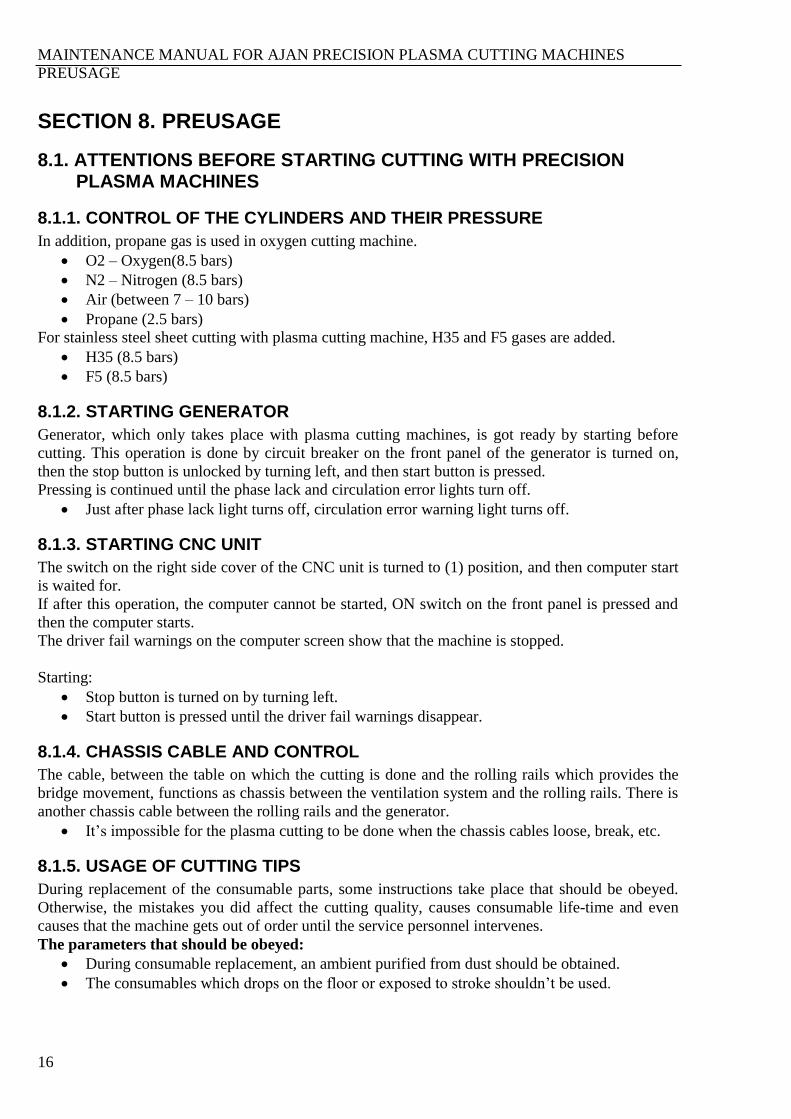
SECTION 10. REPLACEMENT PLANS
Figure 2. General replacement plan
MAINTENANCE MANUAL FOR AJAN PRECISION PLASMA CUTTING MACHINES
REPLACEMENT PLANS
21
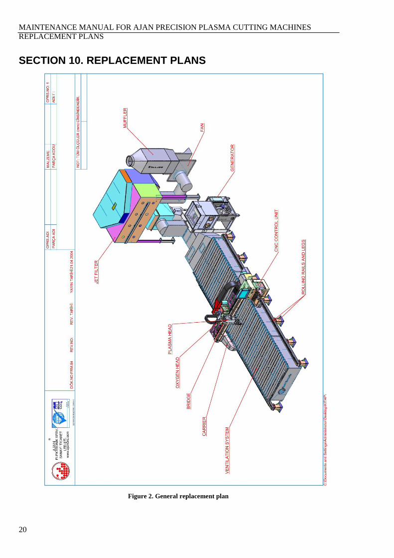
Figure 3. 3000x12000 mm plasma machine with jet filter replacement plan
MAINTENANCE MANUAL FOR AJAN PRECISION PLASMA CUTTING MACHINES
REPLACEMENT PLANS
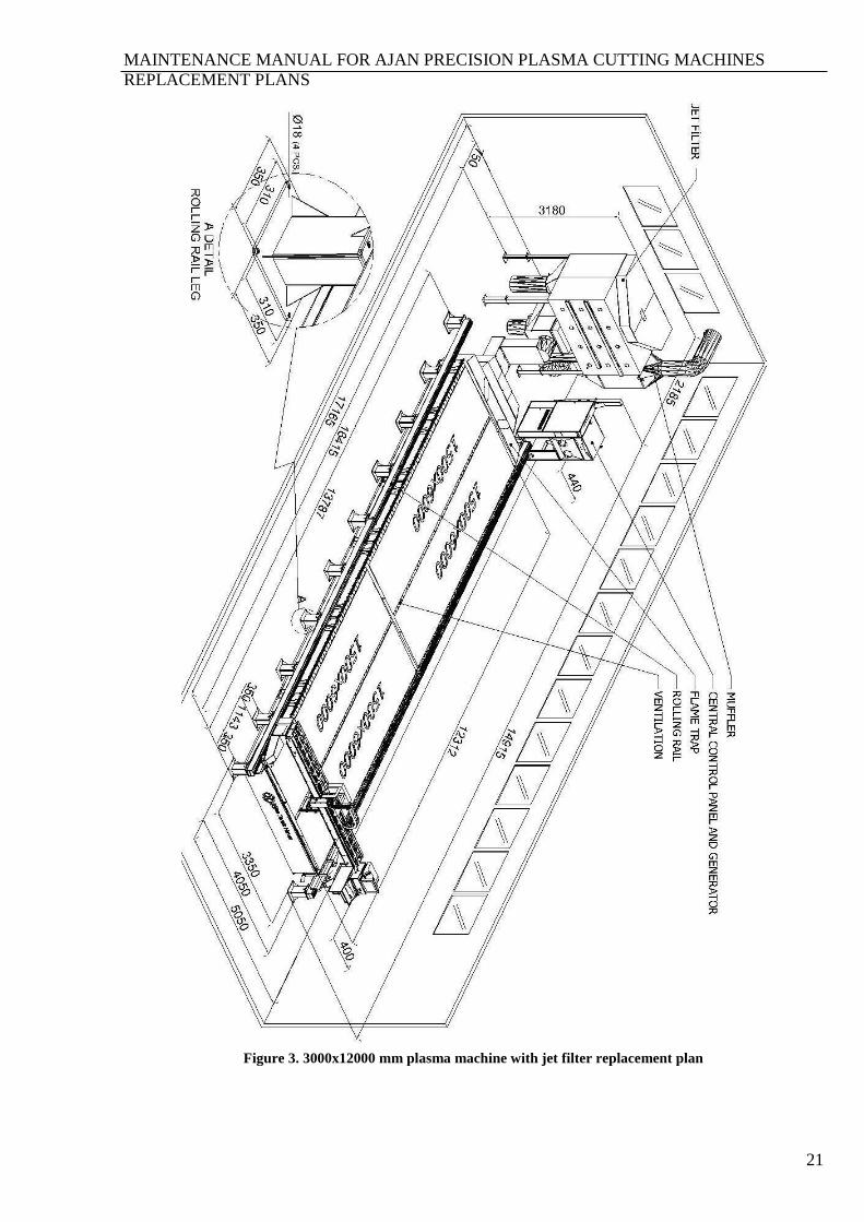
22
Figure 4. 3000x6000 mm plasma machine with jet filter replacement plan
Figure 5. 3000x12000 mm plasma machine without jet filter replacement plan

MAINTENANCE MANUAL FOR AJAN PRECISION PLASMA CUTTING MACHINES
REPLACEMENT PLANS
23
Figure 6. 2000x6000 mm plasma machine without jet filter replacement plan
Figure 7. 2000x6000 mm plasma machine with jet filter replacement plan
MAINTENANCE MANUAL FOR AJAN PRECISION PLASMA CUTTING MACHINES
REPLACEMENT PLANS
24
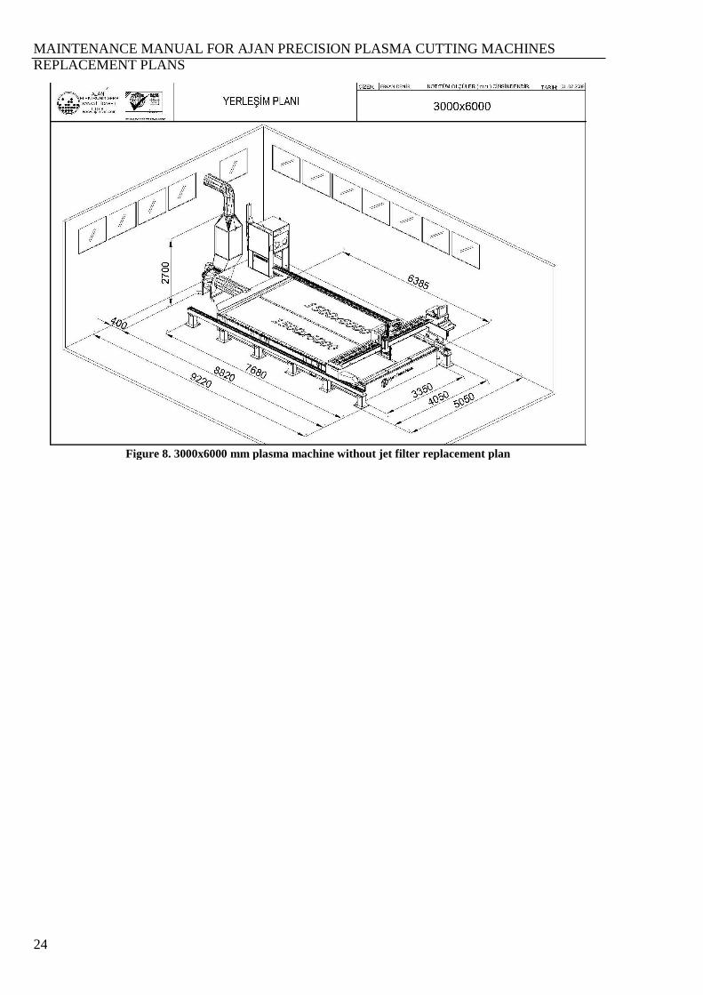
Figure 8. 3000x6000 mm plasma machine without jet filter replacement plan

MAINTENANCE MANUAL FOR AJAN PRECISION PLASMA CUTTING MACHINES
MECHANICAL PARTS
25
SECTION 11. MECHANICAL PARTS
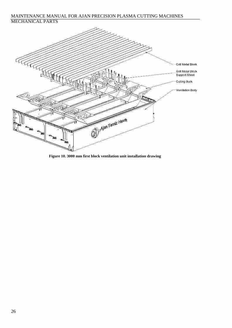
11.1. VENTILATION UNIT
They are the systems sucking and removing the dangerous gases and dust occurring during the
plasma cutting application away from the medium. As the working principle, the air suction occurs
when the pressure handles on the working area are opened by pressure sheet on the machine’s
bridge unit, and it sucks the dust and gas in the cutting area. The sheet to be cut is placed on the grid
blocks. After the cutting process, the dross and some cutting wastes are collected in the cutting
buckets. For a long life and proper operation of the ventilation unit, it should be frequently cleaned
depending on the fullness ratio.
Figure 9. 3000 mm first block ventilation system
MAINTENANCE MANUAL FOR AJAN PRECISION PLASMA CUTTING MACHINES
MECHANICAL PARTS
26
Figure 10. 3000 mm first block ventilation unit installation drawing
MAINTENANCE MANUAL FOR AJAN PRECISION PLASMA CUTTING MACHINES
MECHANICAL PARTS
27
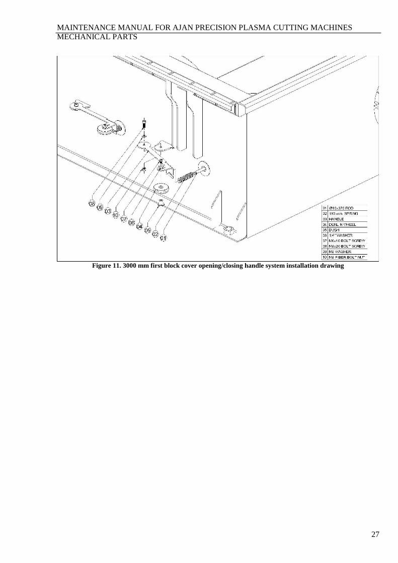
Figure 11. 3000 mm first block cover opening/closing handle system installation drawing
MAINTENANCE MANUAL FOR AJAN PRECISION PLASMA CUTTING MACHINES
MECHANICAL PARTS
28
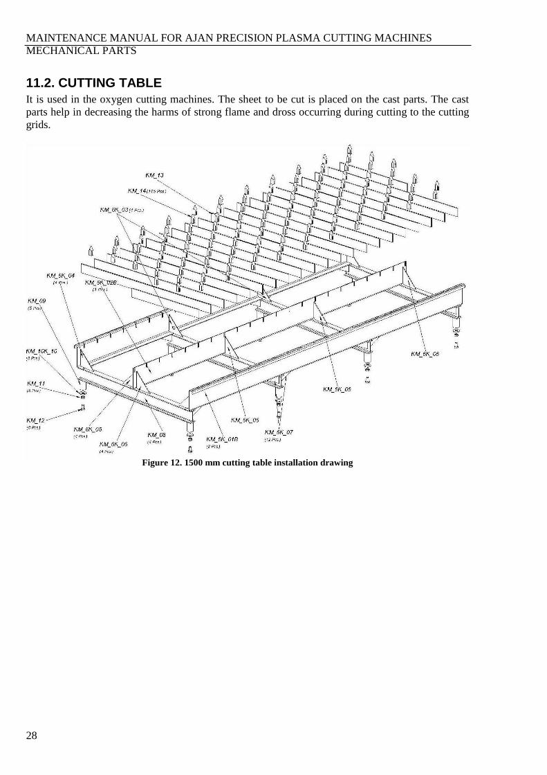
11.2. CUTTING TABLE
It is used in the oxygen cutting machines. The sheet to be cut is placed on the cast parts. The cast
parts help in decreasing the harms of strong flame and dross occurring during cutting to the cutting
grids.
Figure 12. 1500 mm cutting table installation drawing
MAINTENANCE MANUAL FOR AJAN PRECISION PLASMA CUTTING MACHINES
MECHANICAL PARTS
29
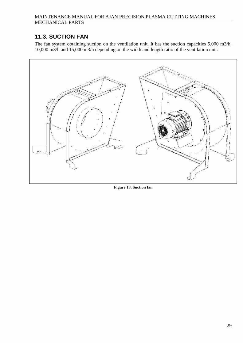
11.3. SUCTION FAN
The fan system obtaining suction on the ventilation unit. It has the suction capacities 5,000 m3/h,
10,000 m3/h and 15,000 m3/h depending on the width and length ratio of the ventilation unit.
Figure 13. Suction fan
MAINTENANCE MANUAL FOR AJAN PRECISION PLASMA CUTTING MACHINES
MECHANICAL PARTS
30
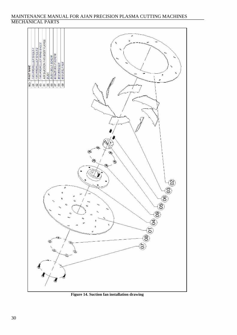
Figure 14. Suction fan installation drawing
MAINTENANCE MANUAL FOR AJAN PRECISION PLASMA CUTTING MACHINES
MECHANICAL PARTS
31
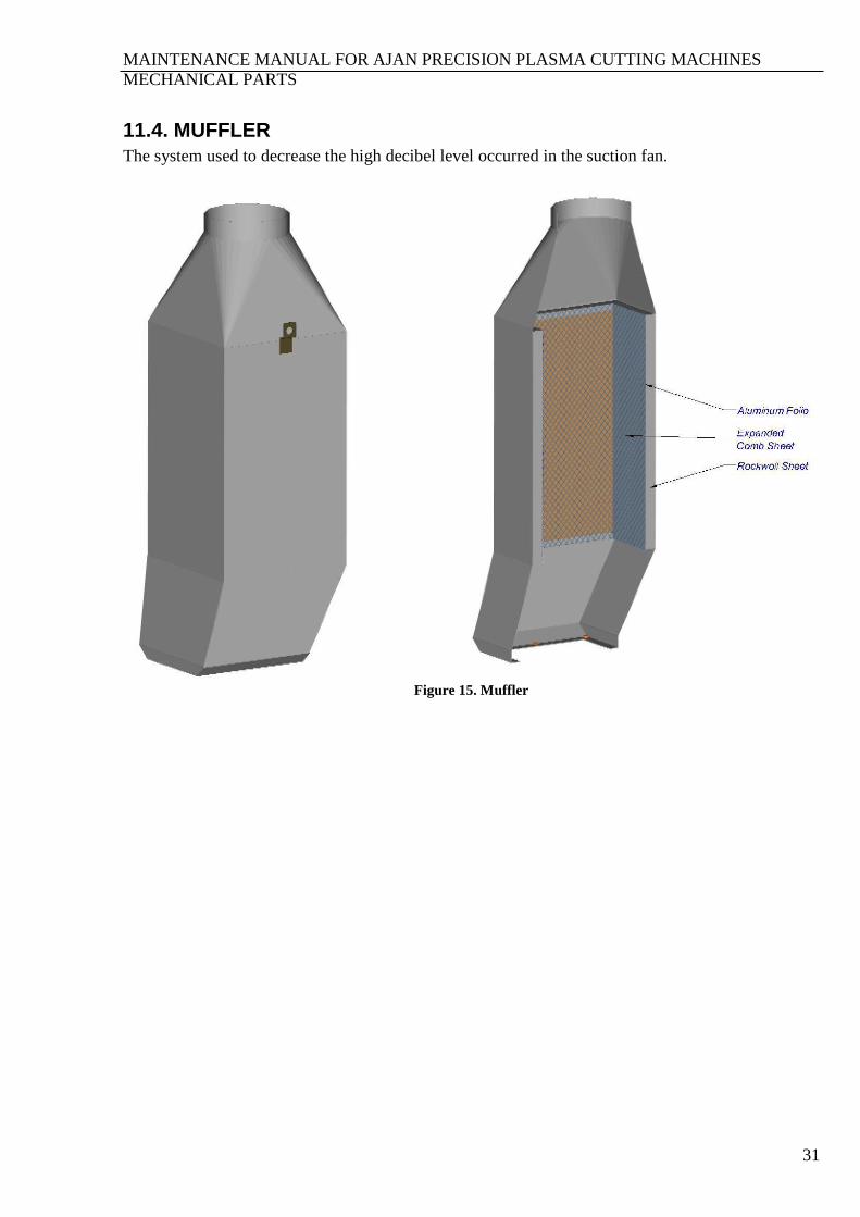
11.4. MUFFLER
The system used to decrease the high decibel level occurred in the suction fan.
Figure 15. Muffler

MAINTENANCE MANUAL FOR AJAN PRECISION PLASMA CUTTING MACHINES
MECHANICAL PARTS
32
11.5. JET FILTER
Figure 16. Jet filter
MAINTENANCE MANUAL FOR AJAN PRECISION PLASMA CUTTING MACHINES
MECHANICAL PARTS
33
MAINTENANCE MANUAL FOR AJAN PRECISION PLASMA CUTTING MACHINES
MECHANICAL PARTS
34
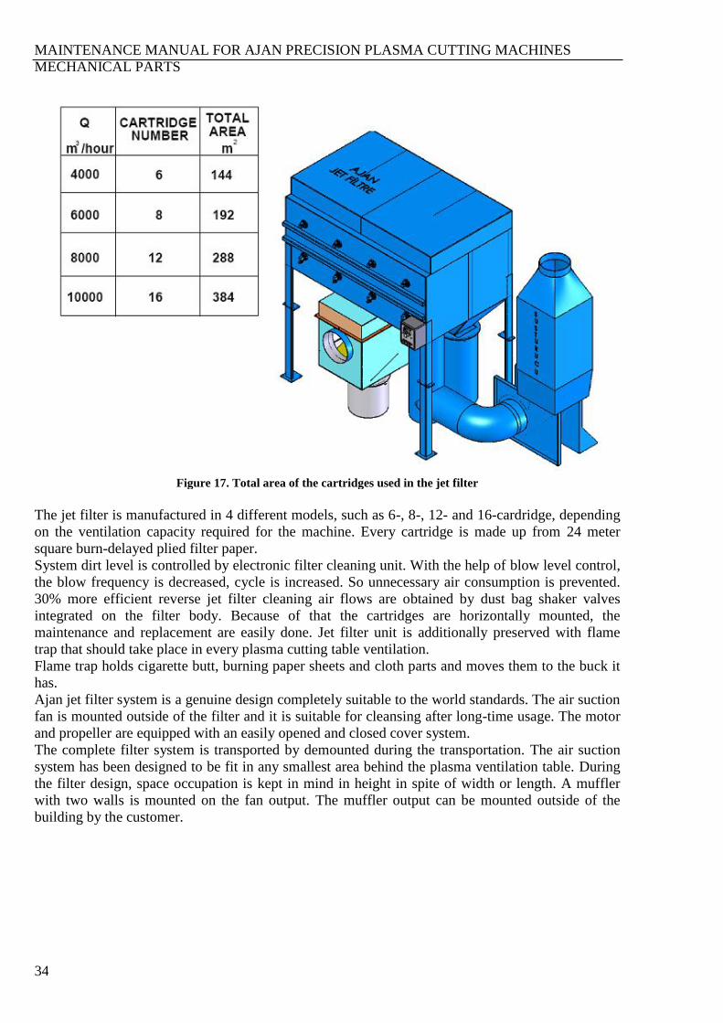
Figure 17. Total area of the cartridges used in the jet filter
The jet filter is manufactured in 4 different models, such as 6-, 8-, 12- and 16-cardridge, depending
on the ventilation capacity required for the machine. Every cartridge is made up from 24 meter
square burn-delayed plied filter paper.
System dirt level is controlled by electronic filter cleaning unit. With the help of blow level control,
the blow frequency is decreased, cycle is increased. So unnecessary air consumption is prevented.
30% more efficient reverse jet filter cleaning air flows are obtained by dust bag shaker valves
integrated on the filter body. Because of that the cartridges are horizontally mounted, the
maintenance and replacement are easily done. Jet filter unit is additionally preserved with flame
trap that should take place in every plasma cutting table ventilation.
Flame trap holds cigarette butt, burning paper sheets and cloth parts and moves them to the buck it
has.
Ajan jet filter system is a genuine design completely suitable to the world standards. The air suction
fan is mounted outside of the filter and it is suitable for cleansing after long-time usage. The motor
and propeller are equipped with an easily opened and closed cover system.
The complete filter system is transported by demounted during the transportation. The air suction
system has been designed to be fit in any smallest area behind the plasma ventilation table. During
the filter design, space occupation is kept in mind in height in spite of width or length. A muffler
with two walls is mounted on the fan output. The muffler output can be mounted outside of the
building by the customer.
MAINTENANCE MANUAL FOR AJAN PRECISION PLASMA CUTTING MACHINES
MECHANICAL PARTS
35
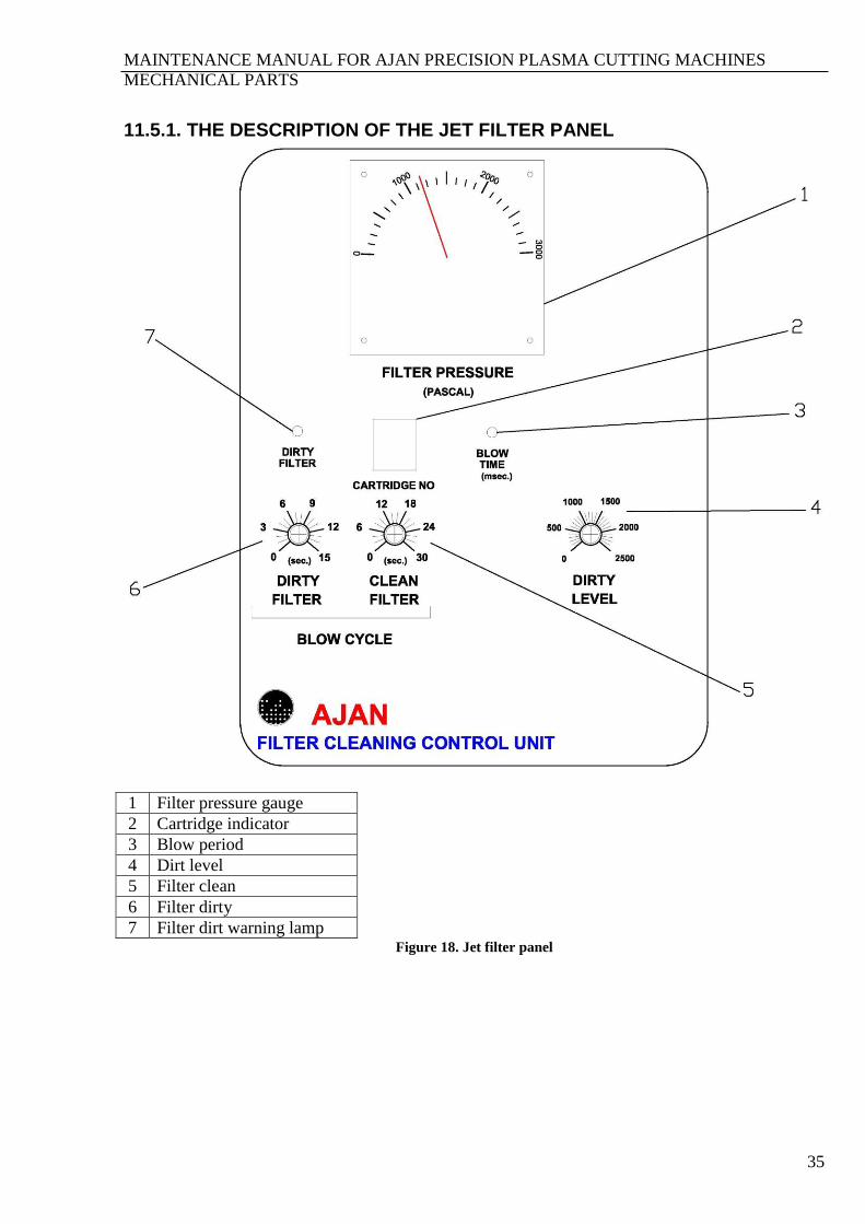
11.5.1. THE DESCRIPTION OF THE JET FILTER PANEL
1 Filter pressure gauge
2 Cartridge indicator
3 Blow period
4 Dirt level
5 Filter clean
6 Filter dirty
7 Filter dirt warning lamp Figure 18. Jet filter panel
MAINTENANCE MANUAL FOR AJAN PRECISION PLASMA CUTTING MACHINES
MECHANICAL PARTS
36
1. FILTER PRESSURE GAUGE:
The permeability of the jet filter cartridge is decreased by fullness, and so pressure on the
cartridges gets high. The fullness of the cartridge is observed by the pressure gauge. 700-
2,000 Pascal value means workable level; however 2,000-3,000 Pascal value means a
critical operation level in Ajan brand jet filters. The cartridges should be replaced when
critical values are reached. The cartridges used in Ajan jet filter systems are made from
flame-retardant paper and the m2 values are shown in Figure 17.
WARNING:
Do not use any cartridge not approved by the manufacturer in Ajan jet filter systems.
2. CARTRIDGE INDICATOR:
The filter unit blows in adjusted periods in order to clean the cartridges. This indicator
indicates the cartridge group to be blowen.
3. BLOW CYCLE:
Synchronized to other adjustments.
4. DIRT LEVEL:
It is used to determine the cartridge dirt level. The cartridge blow cycles are adjusted
depending on the determined dirt level (the ideal value is 1,000 Pascal).
5. FILTER CLEAN:
It is used to adjust the blow cycle when the filter is in clean mode (the ideal value is 15 sec.).
6. FILTER DIRTY:
It is used to adjust the blow cycle when the filter is in dirt mode (the ideal value is 6 sec.).
7. FILTER DIRT WARNING LAMP:
The LED that warns that the filters reached the determined dirt level.
MAINTENANCE MANUAL FOR AJAN PRECISION PLASMA CUTTING MACHINES
MECHANICAL PARTS
37
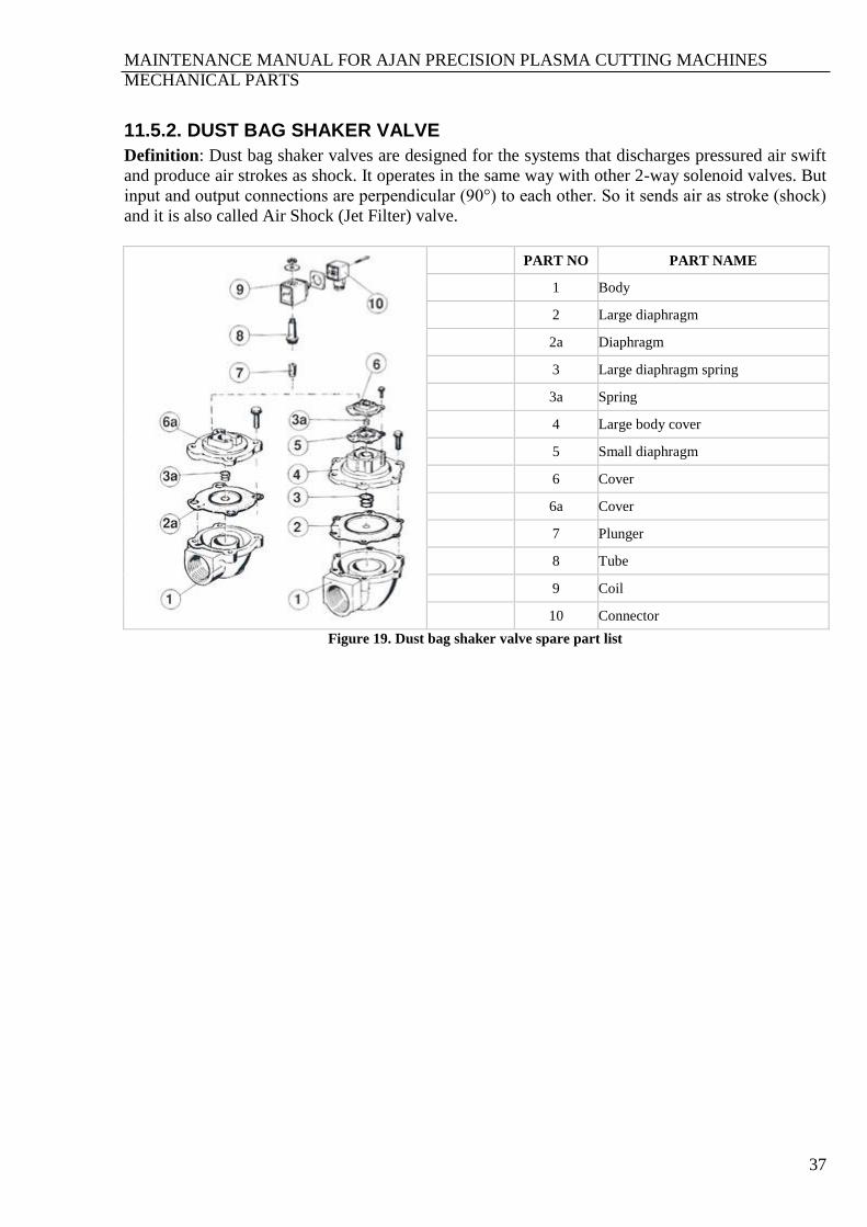
11.5.2. DUST BAG SHAKER VALVE
Definition: Dust bag shaker valves are designed for the systems that discharges pressured air swift
and produce air strokes as shock. It operates in the same way with other 2-way solenoid valves. But
input and output connections are perpendicular (90°) to each other. So it sends air as stroke (shock)
and it is also called Air Shock (Jet Filter) valve.
PART NO PART NAME
1 Body
2 Large diaphragm
2a Diaphragm
3 Large diaphragm spring
3a Spring
4 Large body cover
5 Small diaphragm
6 Cover
6a Cover
7 Plunger
8 Tube
9 Coil
10 Connector
Figure 19. Dust bag shaker valve spare part list

MAINTENANCE MANUAL FOR AJAN PRECISION PLASMA CUTTING MACHINES
MECHANICAL PARTS
38
11.6. PLASMA HEAD UNIT
Figure 20. Plasma head installation drawing
The system supplying plasma torch movement
MAINTENANCE MANUAL FOR AJAN PRECISION PLASMA CUTTING MACHINES
MECHANICAL PARTS
39
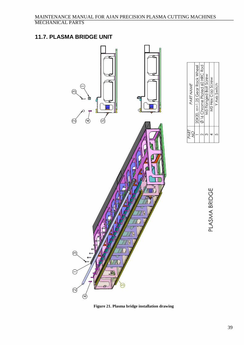
11.7. PLASMA BRIDGE UNIT
Figure 21. Plasma bridge installation drawing
MAINTENANCE MANUAL FOR AJAN PRECISION PLASMA CUTTING MACHINES
MECHANICAL PARTS
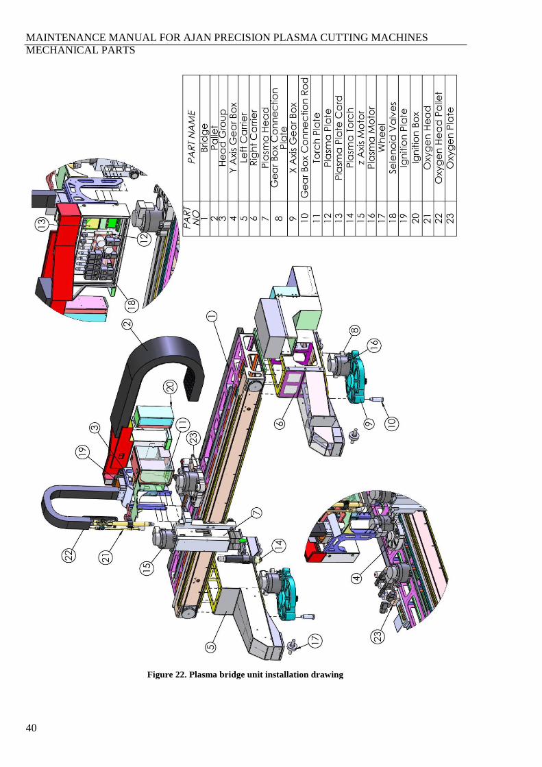
40
Figure 22. Plasma bridge unit installation drawing

MAINTENANCE MANUAL FOR AJAN PRECISION PLASMA CUTTING MACHINES
MECHANICAL PARTS
41
11.8. X AXIS GEARBOX
Figure 23. X axis gearbox installation drawing
The system supplying machine
movement in X axis
MAINTENANCE MANUAL FOR AJAN PRECISION PLASMA CUTTING MACHINES
MECHANICAL PARTS
42
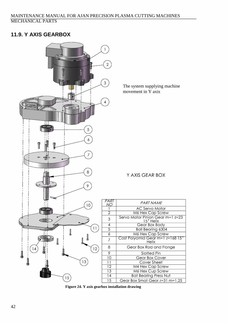
11.9. Y AXIS GEARBOX
Figure 24. Y axis gearbox installation drawing
The system supplying machine
movement in Y axis
MAINTENANCE MANUAL FOR AJAN PRECISION PLASMA CUTTING MACHINES
MECHANICAL PARTS
43
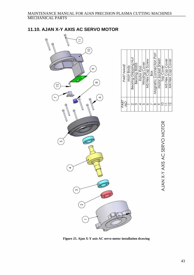
11.10. AJAN X-Y AXIS AC SERVO MOTOR
Figure 25. Ajan X-Y axis AC servo motor installation drawing
MAINTENANCE MANUAL FOR AJAN PRECISION PLASMA CUTTING MACHINES
MECHANICAL PARTS
44
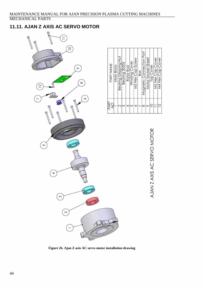
11.11. AJAN Z AXIS AC SERVO MOTOR
Figure 26. Ajan Z axis AC servo motor installation drawing
MAINTENANCE MANUAL FOR AJAN PRECISION PLASMA CUTTING MACHINES
MECHANICAL PARTS
45
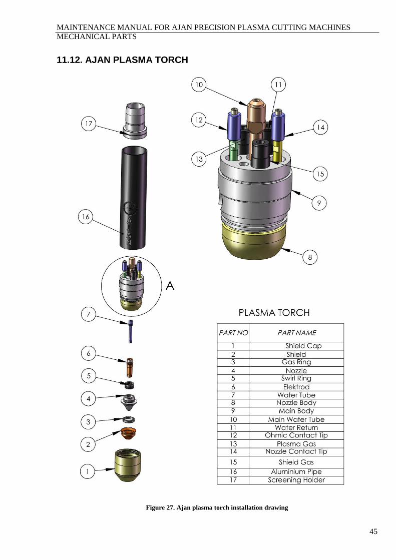
11.12. AJAN PLASMA TORCH
Figure 27. Ajan plasma torch installation drawing

MAINTENANCE MANUAL FOR AJAN PRECISION PLASMA CUTTING MACHINES
MECHANICAL PARTS
46
MAINTENANCE MANUAL FOR AJAN PRECISION PLASMA CUTTING MACHINES
MECHANICAL PARTS
47
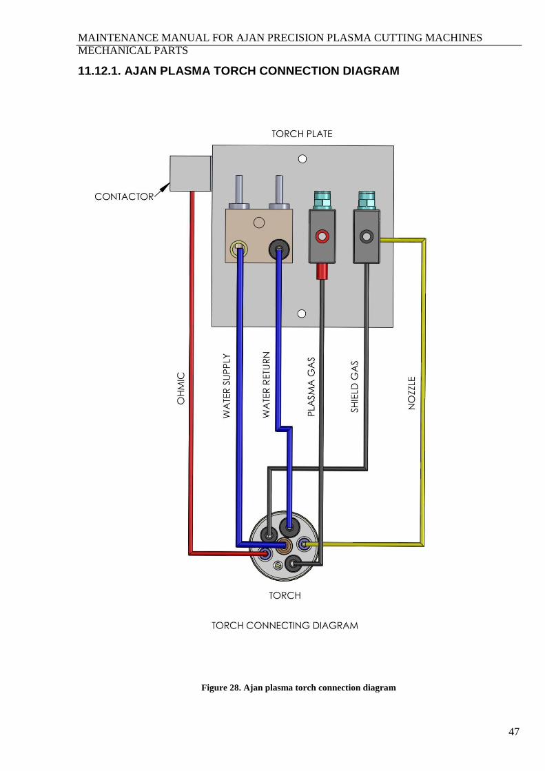
11.12.1. AJAN PLASMA TORCH CONNECTION DIAGRAM
Figure 28. Ajan plasma torch connection diagram
MAINTENANCE MANUAL FOR AJAN PRECISION PLASMA CUTTING MACHINES
MECHANICAL PARTS
48
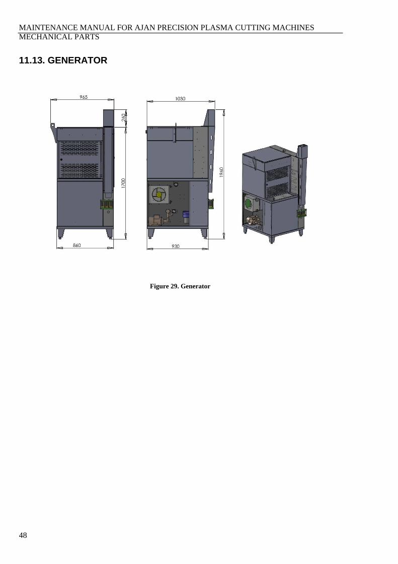
11.13. GENERATOR
Figure 29. Generator

MAINTENANCE MANUAL FOR AJAN PRECISION PLASMA CUTTING MACHINES
MECHANICAL PARTS
49
11.13.1. TORCH COOLING SYSTEM
The plasma generator torch cooling tank is emptied before transportation and 20 lt. cooling liquid is
transported in the generator with the machine. A mixture of 30% Propileneglicol (C3H8O2), 69.9%
deionized water and 0.1% Benzotriazole (C6H5N3) is suggested for Ajan cooling liquid. This
mixture prevents freezing up to –12°C.
Warning: The operations in colder than the above indicated degree, the propileneglicol ratio should
be increased. For the required ratios and material supply, please contact the manufacturer company.
WARNING
Figure 30. Torch cooling liquid drum warning label
The cooling liquid may cause skin and eye irritation, and if swallowed, it may be harmful or fatal.
Propileneglicol and benzotriazole may harm skin and eyes. Please keep the labels on the drums. In
any contact, wash the skin or eyes. If swallowed, drink water and call the doctor. Do not try to
regurgitate.
Warning: Use always propileneglicol in the mixture of cooling liquid. Do not use automotive
antifreeze liquids in spite of propileneglicol.
Use always pure water in the mixture of cooling water in order to prevent failures that may occur in
the pump and oxidation in torch cooling system.

MAINTENANCE MANUAL FOR AJAN PRECISION PLASMA CUTTING MACHINES
MECHANICAL PARTS
50
11.14. CNC UNIT
Figure 31. CNC unit

MAINTENANCE MANUAL FOR AJAN PRECISION PLASMA CUTTING MACHINES
MECHANICAL PARTS
51
11.15. GENERATOR CONNECTION
Figure 32. Generator connection diagram

MAINTENANCE MANUAL FOR AJAN PRECISION PLASMA CUTTING MACHINES
CABLES
52
SECTION 12. CABLES
12.1. INTERFACE SHEET CONNECTION CABLES
Figure 33. Interface sheet connection cables
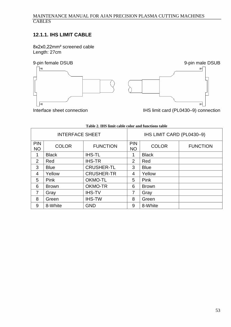
MAINTENANCE MANUAL FOR AJAN PRECISION PLASMA CUTTING MACHINES
CABLES
53
12.1.1. IHS LIMIT CABLE
8x2x0,22mm² screened cable Length: 27cm 9-pin female DSUB 9-pin male DSUB
Interface sheet connection IHS limit card (PL0430–9) connection
Table 2. IHS limit cable color and functions table
INTERFACE SHEET IHS LIMIT CARD (PL0430–9)
PIN NO
COLOR FUNCTION PIN NO
COLOR FUNCTION
1 Black IHS-TL 1 Black
2 Red IHS-TR 2 Red
3 Blue CRUSHER-TL 3 Blue
4 Yellow CRUSHER-TR 4 Yellow
5 Pink OKMO-TL 5 Pink
6 Brown OKMO-TR 6 Brown
7 Gray IHS-TV 7 Gray
8 Green IHS-TW 8 Green
9 8-White GND 9 8-White
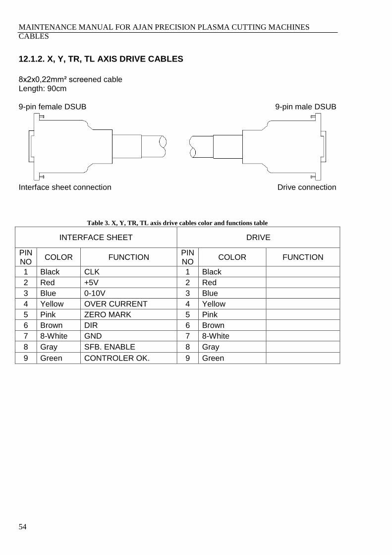
MAINTENANCE MANUAL FOR AJAN PRECISION PLASMA CUTTING MACHINES
CABLES
54
12.1.2. X, Y, TR, TL AXIS DRIVE CABLES
8x2x0,22mm² screened cable Length: 90cm 9-pin female DSUB 9-pin male DSUB
Interface sheet connection Drive connection
Table 3. X, Y, TR, TL axis drive cables color and functions table
INTERFACE SHEET DRIVE
PIN NO
COLOR FUNCTION PIN NO
COLOR FUNCTION
1 Black CLK 1 Black
2 Red +5V 2 Red
3 Blue 0-10V 3 Blue
4 Yellow OVER CURRENT 4 Yellow
5 Pink ZERO MARK 5 Pink
6 Brown DIR 6 Brown
7 8-White GND 7 8-White
8 Gray SFB. ENABLE 8 Gray
9 Green CONTROLER OK. 9 Green
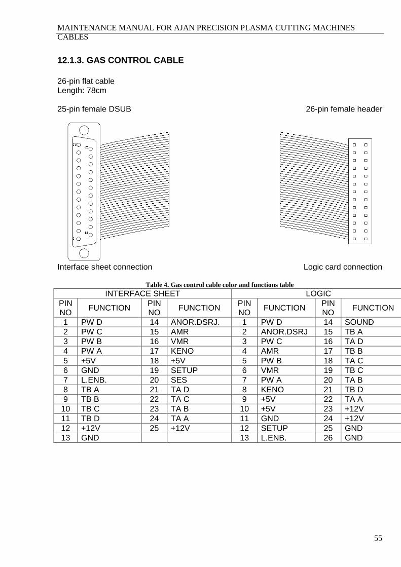
MAINTENANCE MANUAL FOR AJAN PRECISION PLASMA CUTTING MACHINES
CABLES
55
12.1.3. GAS CONTROL CABLE
26-pin flat cable Length: 78cm 25-pin female DSUB 26-pin female header
Interface sheet connection Logic card connection
Table 4. Gas control cable color and functions table
INTERFACE SHEET LOGIC
PIN NO
FUNCTION PIN NO
FUNCTION PIN NO
FUNCTION PIN NO
FUNCTION
1 PW D 14 ANOR.DSRJ. 1 PW D 14 SOUND
2 PW C 15 AMR 2 ANOR.DSRJ 15 TB A
3 PW B 16 VMR 3 PW C 16 TA D
4 PW A 17 KENO 4 AMR 17 TB B
5 +5V 18 +5V 5 PW B 18 TA C
6 GND 19 SETUP 6 VMR 19 TB C
7 L.ENB. 20 SES 7 PW A 20 TA B
8 TB A 21 TA D 8 KENO 21 TB D
9 TB B 22 TA C 9 +5V 22 TA A
10 TB C 23 TA B 10 +5V 23 +12V
11 TB D 24 TA A 11 GND 24 +12V
12 +12V 25 +12V 12 SETUP 25 GND
13 GND 13 L.ENB. 26 GND

MAINTENANCE MANUAL FOR AJAN PRECISION PLASMA CUTTING MACHINES
CABLES
56
12.1.4. RELAY CONTROL KABLOSU
10x0,22mm² screened cable Length: 75cm. 9-pin male DSUB 9-pin female socket
Interface sheet connection Logic card connection
Table 5. Relay control cable color and functions table
INTERFACE SHEET LOGIC CARD
PIN NO
COLOR FUNCTION PIN NO
COLOR FUNCTION
1 Black POL(-) 1 Black
2 Red POL(+) 2 Red
3 Blue M8 3 Blue
4 Yellow ----- 4 Yellow
5 Pink GND 5 Pink
6 Brown SET STOP 6 Brown
7 Violet +5V 7 Violet
8 White RELAY CONTROL 8 White
9 Green SET START 9 Green

MAINTENANCE MANUAL FOR AJAN PRECISION PLASMA CUTTING MACHINES
CABLES
57
12.1.5. GAS CONTROL AND RELAY CONTROL CABLES FUNCTIONS Table 6. Gas control and relay control cables color and functions table
INTERFACE SHEET
PIN NO
CABLE NAME SIGNAL NAME COLOR FUNCTION
1 GAS CONTROL PW D Transmitter selection bits
2 GAS CONTROL PW C
3 GAS CONTROL PW B
Plasma gas-shield gas-current active bits 4 GAS CONTROL PW A
5 GAS CONTROL +5V +5V
6 GAS CONTROL GND GND
7 GAS CONTROL L.ENB. Current or pressure reading-writing bits
8 GAS CONTROL TB A
8-bit current or pressure value information
9 GAS CONTROL TB B
10 GAS CONTROL TB C
11 GAS CONTROL TB D
21 GAS CONTROL TA D
22 GAS CONTROL TA C
23 GAS CONTROL TA B
24 GAS CONTROL TA A
12 GAS CONTROL +12V +12V
13 GAS CONTROL GND GND
14 GAS CONTROL ANOR.DSRJ ---------
15 GAS CONTROL AMR Pressure information analog input
16 GAS CONTROL VMR Voltage information analog input
17 GAS CONTROL KENO
Mode selection bits 1 RELAY CONTROL POL(-) Black
20 GAS CONTROL SOUND
18 GAS CONTROL +5V +5V
19 GAS CONTROL SETUP DRY CUT, Machine type (Pls-Oxy)and plasma right-left selection bits
6 RELAY CONTROL SET STOP Brown
9 RELAY CONTROL SET START Green
25 GAS CONTROL +12V +12V
2 RELAY CONTROL POL(+) Red Marking-cutting bit
3 RELAY CONTROL M8 Blue Plasma start bit
4 RELAY CONTROL ----- Yellow -----
5 RELAY CONTROL GND Pink GND
7 RELAY CONTROL +5V Violet +5V
8 RELAY CONTROL RELAY CONTROL White Relay control bit

MAINTENANCE MANUAL FOR AJAN PRECISION PLASMA CUTTING MACHINES
CABLES
58
12.1.6. HAND CONTROL CABLE
4x0,34 mm² screened cable Length: 225cm. 9-pin female DSUB 5-pin female mic
Interface sheet connection Hand control connection
Table 7. Hand control cable color and functions table
INTERFACE SHEET HAND CONTROL
PIN NO
COLOR FUNCTION PIN NO
COLOR FUNCTION
1 Green +5V 1 Green +5V
2 Brown DATA 2 Brown DATA
3 White CLK 3 White CLK
5 Yellow GND 4 Yellow GND
Screening chassis SCREEN 5 Screening

MAINTENANCE MANUAL FOR AJAN PRECISION PLASMA CUTTING MACHINES
CABLES
59
12.1.7. LIMIT CABLE
16x0,22 mm² screened cable Length: 30cm 15-pin male DSUB 15-pin female DSUB
Interface sheet connection Limit card (PL0306–3) connection
Table 8. Limit cable color and functions table
INTERFACE SHEET LIMIT CARD (PL0306–3)
PIN NO
COLOR FUNCTION PIN NO
COLOR FUNCTION
1 Yellow TL CONT.OK 1 Yellow
2 Violet +TR LIMIT 2 Violet
3 Green -TR LIMIT 3 Green
4 Red +TL LIMIT 4 Red
5 Brown -TL LIMIT 5 Brown
6 Green-Brown GND 6 Green-Brown
7 Gray TW CONT.OK 7 Gray
8 Pink ------ 8 Pink
9 Black GND 9 Black
10 Blue-Red -X LIMIT 10 Blue-Red
11 Blue +X LIMIT 11 Blue
12 Pink-Gray +Y LIMIT 12 Pink-Gray
13 White -Y LIMIT 13 White
14 Green-White GND 14 Green-White
15 Brown-Yellow GND 15 Brown-Yellow
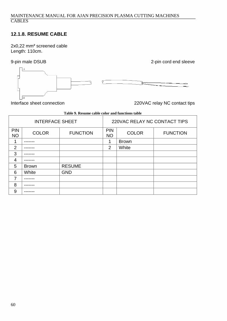
MAINTENANCE MANUAL FOR AJAN PRECISION PLASMA CUTTING MACHINES
CABLES
60
12.1.8. RESUME CABLE
2x0,22 mm² screened cable Length: 110cm. 9-pin male DSUB 2-pin cord end sleeve
Interface sheet connection 220VAC relay NC contact tips
Table 9. Resume cable color and functions table
INTERFACE SHEET 220VAC RELAY NC CONTACT TIPS
PIN NO
COLOR FUNCTION PIN NO
COLOR FUNCTION
1 ------- 1 Brown
2 ------- 2 White
3 -------
4 -------
5 Brown RESUME
6 White GND
7 -------
8 -------
9 -------
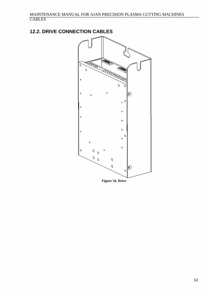
MAINTENANCE MANUAL FOR AJAN PRECISION PLASMA CUTTING MACHINES
CABLES
61
12.2. DRIVE CONNECTION CABLES
Figure 34. Drive
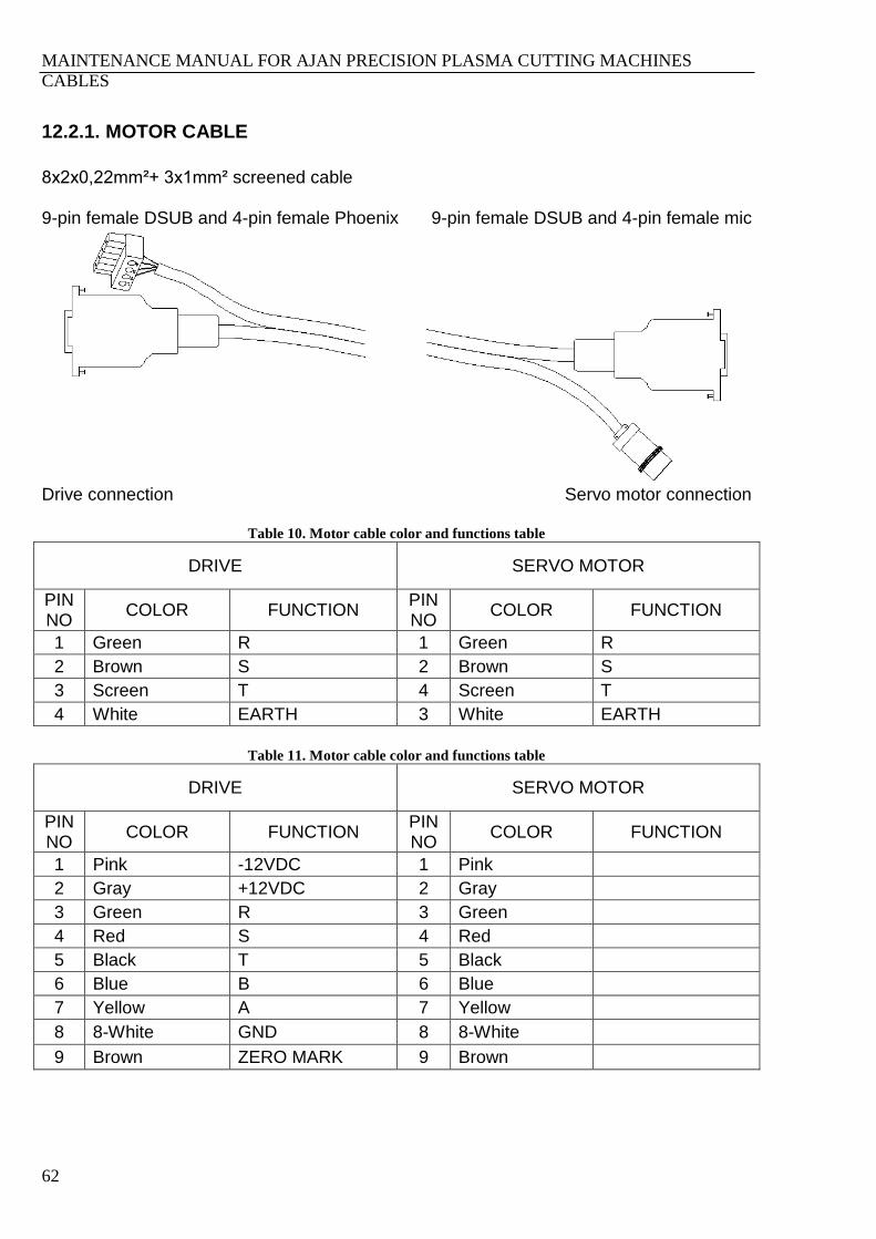
MAINTENANCE MANUAL FOR AJAN PRECISION PLASMA CUTTING MACHINES
CABLES
62
12.2.1. MOTOR CABLE
8x2x0,22mm²+ 3x1mm² screened cable 9-pin female DSUB and 4-pin female Phoenix 9-pin female DSUB and 4-pin female mic
Drive connection Servo motor connection
Table 10. Motor cable color and functions table
DRIVE SERVO MOTOR
PIN NO
COLOR FUNCTION PIN NO
COLOR FUNCTION
1 Green R 1 Green R
2 Brown S 2 Brown S
3 Screen T 4 Screen T
4 White EARTH 3 White EARTH
Table 11. Motor cable color and functions table
DRIVE SERVO MOTOR
PIN NO
COLOR FUNCTION PIN NO
COLOR FUNCTION
1 Pink -12VDC 1 Pink
2 Gray +12VDC 2 Gray
3 Green R 3 Green
4 Red S 4 Red
5 Black T 5 Black
6 Blue B 6 Blue
7 Yellow A 7 Yellow
8 8-White GND 8 8-White
9 Brown ZERO MARK 9 Brown

MAINTENANCE MANUAL FOR AJAN PRECISION PLASMA CUTTING MACHINES
CABLES
63
Table 12. Motor cable lengths with respect to Y axis lengths
MOTOR
CABLE
Y AXIS LENGTH
1500mm 2000mm 2500mm 3000mm 4000mm
XR cable
length 185cm 185cm 185cm 185cm 185cm
XL cable
length 430cm 470cm 525cm 560cm 665cm
Y cable length 620cm 625cm 680cm 755cm 830cm
TR cable
length 605cm 615cm 670cm 745cm 820cm
TL cable
length 650cm 685cm 740cm 815cm 890cm

MAINTENANCE MANUAL FOR AJAN PRECISION PLASMA CUTTING MACHINES
CABLES
64
12.2.2. DRIVE POWER CABLE
10-pin female Phoenix 8-pin female Phoenix
Drive connection Drive transformer connection
Table 13. Drive power cable color and functions table
DRIVE DRIVE TRANSFORMER
PIN NO
COLOR FUNCTION PIN NO
COLOR FUNCTION
1 ----- CURR. + 1 Yellow-Green EARTH
2 ----- CURR. - 2 Blue NEUTR
3 Brown 20VAC 3 Brown 220VAC
4 Yellow-Green 0V ML 4 Blue 0V MH
5 Blue 20VAC 5 Brown 20VAC
6 Brown 20VAC 6 Brown 20VAC
7 Blue 0V MH 7 Yellow-Green 0V ML
8 Yellow-Green EARTH 8 Blue 20VAC
9 Blue 0V MH
10 Brown +80VDC
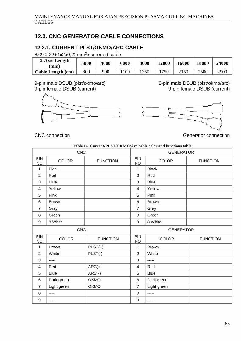
MAINTENANCE MANUAL FOR AJAN PRECISION PLASMA CUTTING MACHINES
CABLES
65
12.3. CNC-GENERATOR CABLE CONNECTIONS
12.3.1. CURRENT-PLST/OKMO/ARC CABLE
8x2x0,22+4x2x0,22mm2 screened cable
X Axis Length
(mm) 3000 4000 6000 8000 12000 16000 18000 24000
Cable Length (cm) 800 900 1100 1350 1750 2150 2500 2900
9-pin male DSUB (plst/okmo/arc) 9-pin female DSUB (current)
9-pin male DSUB (plst/okmo/arc) 9-pin female DSUB (current)
CNC connection Generator connection
Table 14. Current-PLST/OKMO/Arc cable color and functions table
CNC GENERATOR
PIN NO
COLOR FUNCTION PIN NO
COLOR FUNCTION
1 Black 1 Black
2 Red 2 Red
3 Blue 3 Blue
4 Yellow 4 Yellow
5 Pink 5 Pink
6 Brown 6 Brown
7 Gray 7 Gray
8 Green 8 Green
9 8-White 9 8-White
CNC GENERATOR
PIN NO
COLOR FUNCTION PIN NO
COLOR FUNCTION
1 Brown PLST(+) 1 Brown
2 White PLST(-) 2 White
3 ----- 3 -----
4 Red ARC(+) 4 Red
5 Blue ARC(-) 5 Blue
6 Dark green OKMO 6 Dark green
7 Light green OKMO 7 Light green
8 ----- 8 -----
9 ----- 9 -----

MAINTENANCE MANUAL FOR AJAN PRECISION PLASMA CUTTING MACHINES
CABLES
66
12.3.2. REMOTE CONTROL CABLE
12x0,75+4x1,5mm2 cable
X Axis Length
(mm) 3000 4000 6000 8000 12000 16000 18000 24000
Cable Length (cm) 700 950 1100 1300 1800 2100 2500 2900
16-pin female socket 16-pin cord-end sleeve
CNC connection Generator connection
Table 15. Remote control cable color and functions table
CNC CONNECTION GENERATOR
PIN NO
COLOR FUNCTION PIN NO
COLOR FUNCTION
1 1 AIR DRYER(R) 1 1
2 2 AIR DRYER(S) 2 2
3 3 PULSE VALVE(R) 3 3
4 4 PULSE VALVE(S) 4 4
5 5 GEN. NEUTR 5 5
6 6 GEN. STOP 6 6
7 7 GEN. START-STOP 7 7
8 8 GEN. 220VAC START 8 8
9 9 FAN STOP 9 9
10 10 FAN START-STOP 10 10
11 11 FAN 220VAC START 11 11
12 Yellow-Green FAN NEUTR 12 Yellow-Green
13 Brown CNC (R) 13 Brown
14 Blue CNC (S) 14 Blue
15 Black CNC (T) 15 Black
16 Yellow-Green EARTH 16 Yellow-Green

MAINTENANCE MANUAL FOR AJAN PRECISION PLASMA CUTTING MACHINES
CABLES
67
12.3.3. ELECTRODE-NOZZLE CABLE
X Axis Length
(mm) 3000 4000 6000 8000 12000 16000 18000 24000
Cable Length (cm) 700 800 1000 1250 1650 2050 2400 2750
Y Axis Length (mm) 1500 2000 2500 3000 4000
Cable Length (cm) 530 550 575 650 750
50mm² circular lug (electrode) 16mm² circular lug (nozzle)
50mm² circular lug (electrode) 16mm² circular lug (nozzle)
CNC connection Generator connection
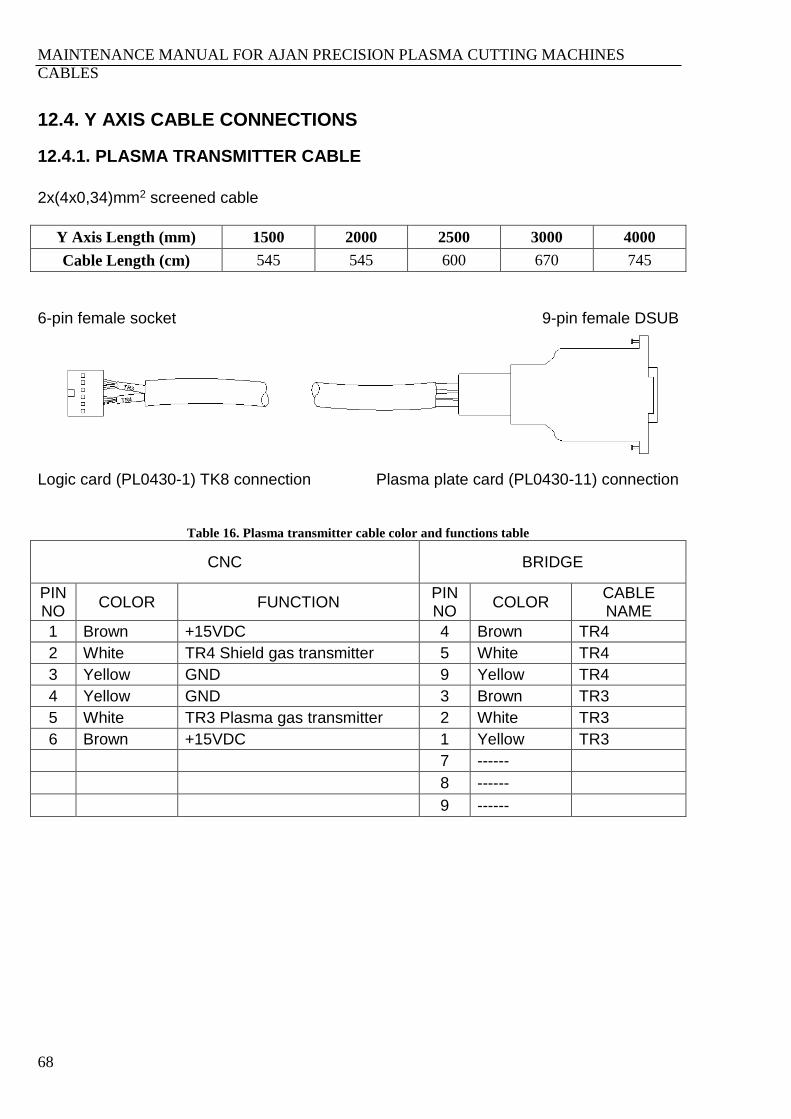
MAINTENANCE MANUAL FOR AJAN PRECISION PLASMA CUTTING MACHINES
CABLES
68
12.4. Y AXIS CABLE CONNECTIONS
12.4.1. PLASMA TRANSMITTER CABLE
2x(4x0,34)mm2 screened cable
Y Axis Length (mm) 1500 2000 2500 3000 4000
Cable Length (cm) 545 545 600 670 745
6-pin female socket 9-pin female DSUB
Logic card (PL0430-1) TK8 connection Plasma plate card (PL0430-11) connection
Table 16. Plasma transmitter cable color and functions table
CNC BRIDGE
PIN NO
COLOR FUNCTION PIN NO
COLOR CABLE NAME
1 Brown +15VDC 4 Brown TR4
2 White TR4 Shield gas transmitter 5 White TR4
3 Yellow GND 9 Yellow TR4
4 Yellow GND 3 Brown TR3
5 White TR3 Plasma gas transmitter 2 White TR3
6 Brown +15VDC 1 Yellow TR3
7 ------
8 ------
9 ------
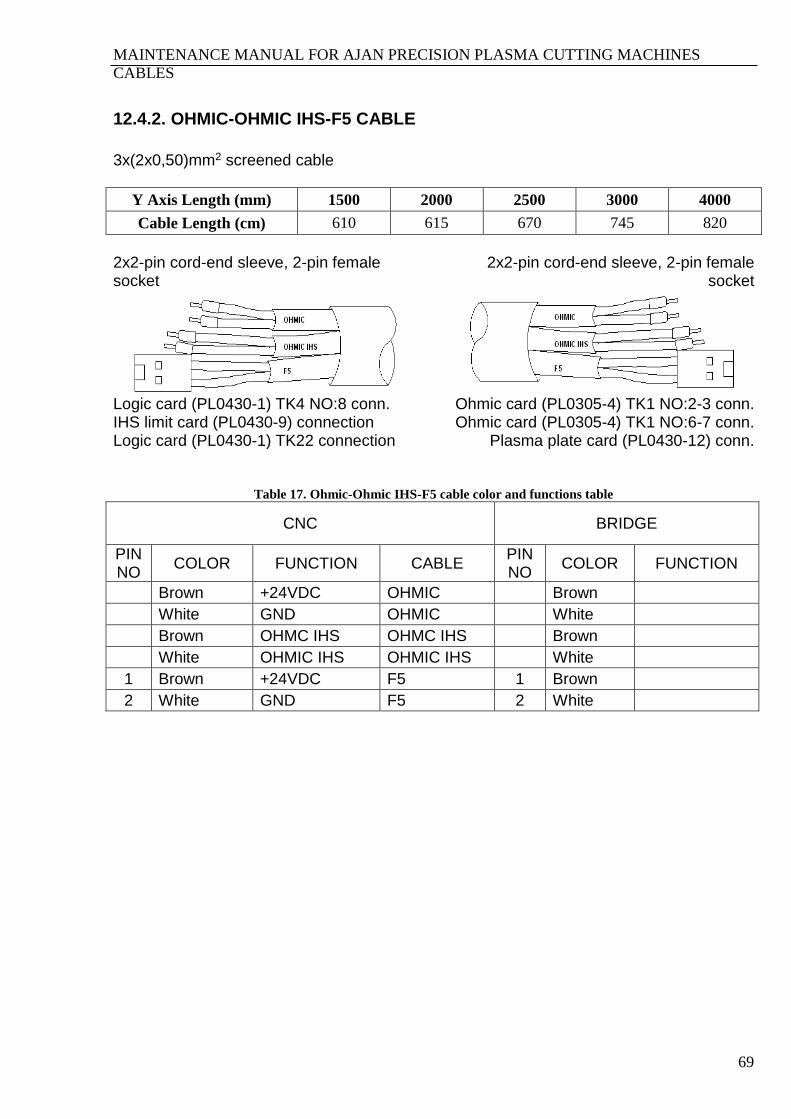
MAINTENANCE MANUAL FOR AJAN PRECISION PLASMA CUTTING MACHINES
CABLES
69
12.4.2. OHMIC-OHMIC IHS-F5 CABLE
3x(2x0,50)mm2 screened cable
Y Axis Length (mm) 1500 2000 2500 3000 4000
Cable Length (cm) 610 615 670 745 820
2x2-pin cord-end sleeve, 2-pin female socket
2x2-pin cord-end sleeve, 2-pin female socket
Logic card (PL0430-1) TK4 NO:8 conn. IHS limit card (PL0430-9) connection Logic card (PL0430-1) TK22 connection
Ohmic card (PL0305-4) TK1 NO:2-3 conn. Ohmic card (PL0305-4) TK1 NO:6-7 conn.
Plasma plate card (PL0430-12) conn.
Table 17. Ohmic-Ohmic IHS-F5 cable color and functions table
CNC BRIDGE
PIN NO
COLOR FUNCTION CABLE PIN NO
COLOR FUNCTION
Brown +24VDC OHMIC Brown
White GND OHMIC White
Brown OHMC IHS OHMC IHS Brown
White OHMIC IHS OHMIC IHS White
1 Brown +24VDC F5 1 Brown
2 White GND F5 2 White

MAINTENANCE MANUAL FOR AJAN PRECISION PLASMA CUTTING MACHINES
CABLES
70
12.4.3. PLASMA VALVE CABLE
4x0,34mm2+2(5x0,34)mm2 screened cable
Y Axis Length (mm) 1500 2000 2500 3000 4000
Cable Length (cm) 525 550 585 660 735
2x10-pin female Phoenix 15-pin female DSUB
Logic card (PL0430-1) TK4, TK2 connection Plasma plate card (PL0430-11) conn.
Table 18. Plasma valve cable color and functions table
CNC BRIDGE
PIN NO
COLOR FUNCTION CABLE NAME
PIN NO
COLOR FUNCTION CABLE NAME
1 Yellow ATM GAS A 1 Green O2 GAS B
2 White AIRS GAS A 2 Yellow AIR GAS B
3 Brown +24VDC GAS A 3 ----- ----- -----
4 Green N2S GAS A 4 Brown +24VDC GAS B
5 Gray O2S GAS A 5 White N2 GAS B
6 Yellow AIR GAS B 6 Gray H35 GAS B
7 White N2 GAS B 7 Yellow PV3 PV3
8 Brown +24VDC GAS B 8 Brown +24VDC PV3
9 Green O2 GAS B 9 Gray O2S GAS A
10 Gray H35 GAS B 10 White AIRS GAS A
11 Brown +24VDC GAS A
3 Brown +24VDC PV3 12 ------ ------ ------
4 Yellow PV3 Plasma gas servo valve
PV3 13 Green N2S GAS A
5 White PV4 Shield gas servo valve
PV3 14 Yellow ATM GAS A
15 white PV4 PV3
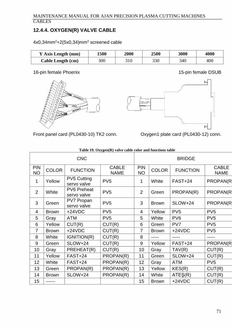
MAINTENANCE MANUAL FOR AJAN PRECISION PLASMA CUTTING MACHINES
CABLES
71
12.4.4. OXYGEN(R) VALVE CABLE
4x0,34mm2+2(5x0,34)mm2 screened cable
Y Axis Length (mm) 1500 2000 2500 3000 4000
Cable Length (cm) 300 310 330 340 400
16-pin female Phoenix 15-pin female DSUB
Front panel card (PL0430-10) TK2 conn. Oxygen1 plate card (PL0430-12) conn.
Table 19. Oxygen(R) valve cable color and functions table
CNC BRIDGE
PIN NO
COLOR FUNCTION CABLE NAME
PIN NO
COLOR FUNCTION CABLE NAME
1 Yellow PV5 Cutting servo valve
PV5 1 White FAST+24 PROPAN(R)
2 White PV6 Preheat servo valve
PV5 2 Green PROPAN(R) PROPAN(R)
3 Green PV7 Propan servo valve
PV5 3 Brown SLOW+24 PROPAN(R)
4 Brown +24VDC PV5 4 Yellow PV5 PV5
5 Gray ATM PV5 5 White PV6 PV5
6 Yellow CUT(R) CUT(R) 6 Green PV7 PV5
7 Brown +24VDC CUT(R) 7 Brown +24VDC PV5
8 White IGNITION(R) CUT(R) 8 ----- ----- -----
9 Green SLOW+24 CUT(R) 9 Yellow FAST+24 PROPAN(R)
10 Gray PREHEAT(R) CUT(R) 10 Gray TAV(R) CUT(R)
11 Yellow FAST+24 PROPAN(R) 11 Green SLOW+24 CUT(R)
12 White FAST+24 PROPAN(R) 12 Gray ATM PV5
13 Green PROPAN(R) PROPAN(R) 13 Yellow KES(R) CUT(R)
14 Brown SLOW+24 PROPAN(R) 14 White ATEŞ(R) CUT(R)
15 ------ 15 Brown +24VDC CUT(R)
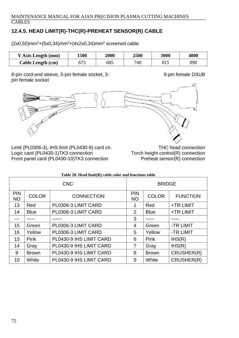
MAINTENANCE MANUAL FOR AJAN PRECISION PLASMA CUTTING MACHINES
CABLES
72
12.4.5. HEAD LIMIT(R)-THC(R)-PREHEAT SENSOR(R) CABLE
(2x0,50)mm2+(5x0,34)mm2+(4x2x0,34)mm2 screened cable
Y Axis Length (mm) 1500 2000 2500 3000 4000
Cable Length (cm) 675 685 740 815 890
8-pin cord-end sleeve, 5-pin female socket, 3-pin female socket
9-pin female DSUB
Limit (PL0306-3), IHS limit (PL0430-9) card cn. Logic card (PL0430-1)TK3 connection Front panel card (PL0430-10)TK3 connection
THC head connection Torch height control(R) connection
Preheat sensor(R) connection
Table 20. Head limit(R) cable color and functions table
CNC BRIDGE
PIN NO
COLOR CONNECTION PIN NO
COLOR FUNCTION
13 Red PL0306-3 LIMIT CARD 1 Red +TR LIMIT
14 Blue PL0306-3 LIMIT CARD 2 Blue +TR LIMIT
--- ----- ------ 3 ----- -----
15 Green PL0306-3 LIMIT CARD 4 Green -TR LIMIT
16 Yellow PL0306-3 LIMIT CARD 5 Yellow -TR LIMIT
13 Pink PL0430-9 IHS LIMIT CARD 6 Pink IHS(R)
14 Gray PL0430-9 IHS LIMIT CARD 7 Gray IHS(R)
9 Brown PL0430-9 IHS LIMIT CARD 8 Brown CRUSHER(R)
10 White PL0430-9 IHS LIMIT CARD 9 White CRUSHER(R)
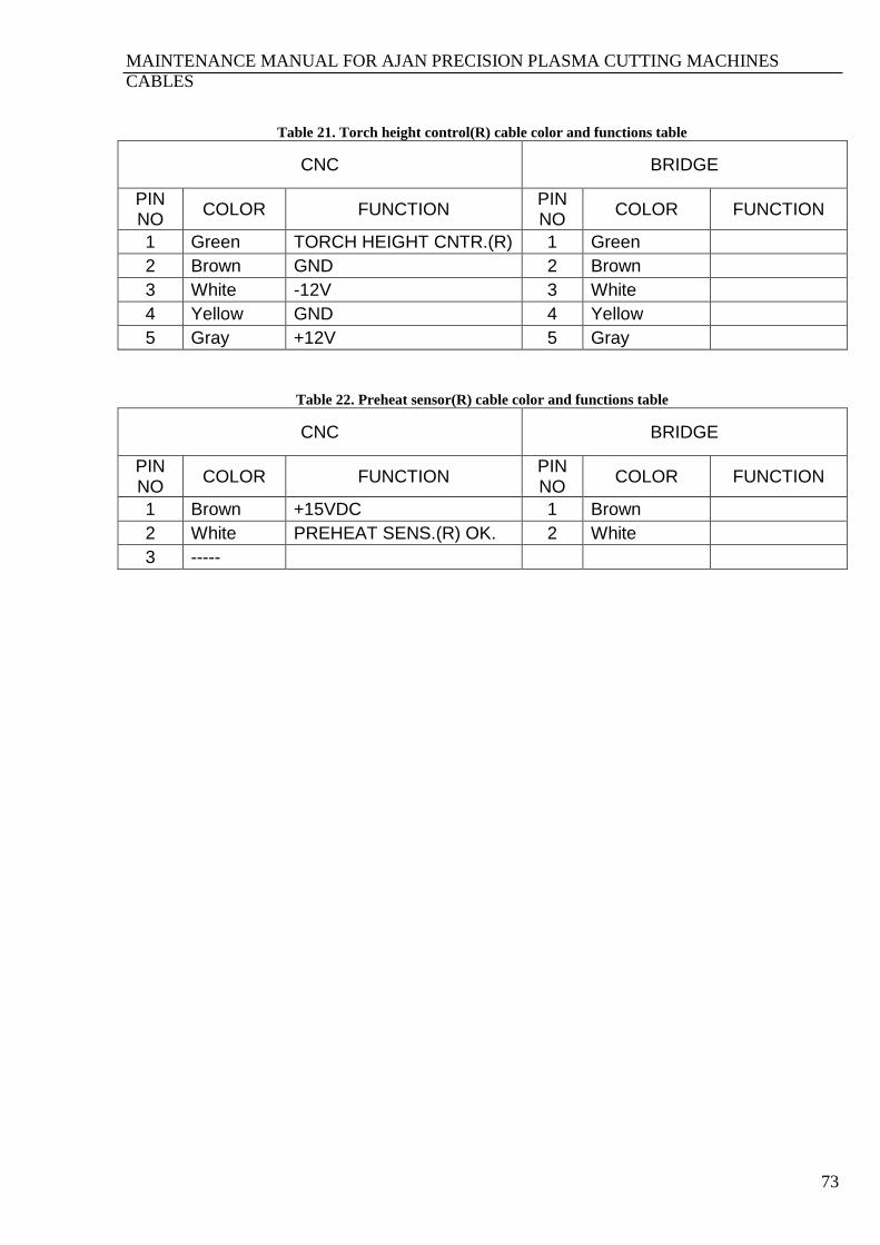
MAINTENANCE MANUAL FOR AJAN PRECISION PLASMA CUTTING MACHINES
CABLES
73
Table 21. Torch height control(R) cable color and functions table
CNC BRIDGE
PIN NO
COLOR FUNCTION PIN NO
COLOR FUNCTION
1 Green TORCH HEIGHT CNTR.(R) 1 Green
2 Brown GND 2 Brown
3 White -12V 3 White
4 Yellow GND 4 Yellow
5 Gray +12V 5 Gray
Table 22. Preheat sensor(R) cable color and functions table
CNC BRIDGE
PIN NO
COLOR FUNCTION PIN NO
COLOR FUNCTION
1 Brown +15VDC 1 Brown
2 White PREHEAT SENS.(R) OK. 2 White
3 -----
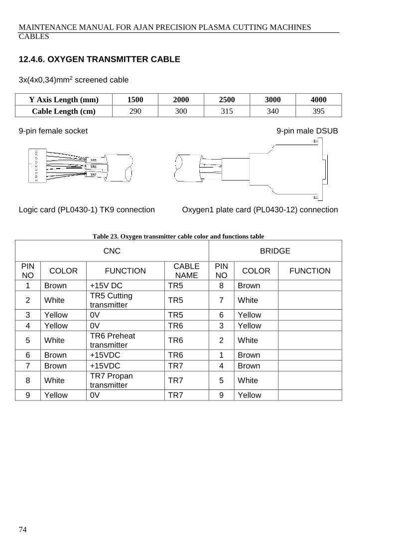
MAINTENANCE MANUAL FOR AJAN PRECISION PLASMA CUTTING MACHINES
CABLES
74
12.4.6. OXYGEN TRANSMITTER CABLE
3x(4x0,34)mm2 screened cable
Y Axis Length (mm) 1500 2000 2500 3000 4000
Cable Length (cm) 290 300 315 340 395
9-pin female socket 9-pin male DSUB
Logic card (PL0430-1) TK9 connection Oxygen1 plate card (PL0430-12) connection
Table 23. Oxygen transmitter cable color and functions table
CNC BRIDGE
PIN NO
COLOR FUNCTION CABLE NAME
PIN NO
COLOR FUNCTION
1 Brown +15V DC TR5 8 Brown
2 White TR5 Cutting transmitter
TR5 7 White
3 Yellow 0V TR5 6 Yellow
4 Yellow 0V TR6 3 Yellow
5 White TR6 Preheat transmitter
TR6 2 White
6 Brown +15VDC TR6 1 Brown
7 Brown +15VDC TR7 4 Brown
8 White TR7 Propan transmitter
TR7 5 White
9 Yellow 0V TR7 9 Yellow

MAINTENANCE MANUAL FOR AJAN PRECISION PLASMA CUTTING MACHINES
CABLES
75
12.4.7. OXYGEN(L) VALVE CABLE
4x0,34mm2+5x0,34mm2 screened cable
Y Axis Length (mm) 1500 2000 2500 3000 4000
Cable Length (cm) 360 375 395 415 470
16-pin female Phoenix 9-pin female DSUB
Front panel card2 (PL0430-10) TK2 conn. Oxygen2 plate card (PL0430-14) conn.
Table 24. Oxygen(L) valve cable color and functions table
CNC BRIDGE
PIN NO
COLOR FUNCTION CABLE NAME
PIN NO
COLOR FUNCTION CABLE NAME
11 Yellow FAST +24 PROPAN(L) 1 Brown PROPAN(L)
12 White FAST +24 PROPAN(L) 2 Green PROPAN(L)
13 Green PROPAN(L) PROPAN(L) 3 White PROPAN(L)
14 Brown SLOW +24 PROPAN(L) 4 Yellow CUT(L)
6 Yellow CUT(L) CUT(L) 5 Brown CUT(L)
7 Brown +24VDC CUT(L) 6 Green CUT(L)
8 White IGNITON(L) CUT(L) 7 Gray CUT(L)
9 Green SLOW +24 CUT(L) 8 Yellow PROPAN(L)
10 Gray PREHEAT(L) CUT(L) 9 White CUT(L)
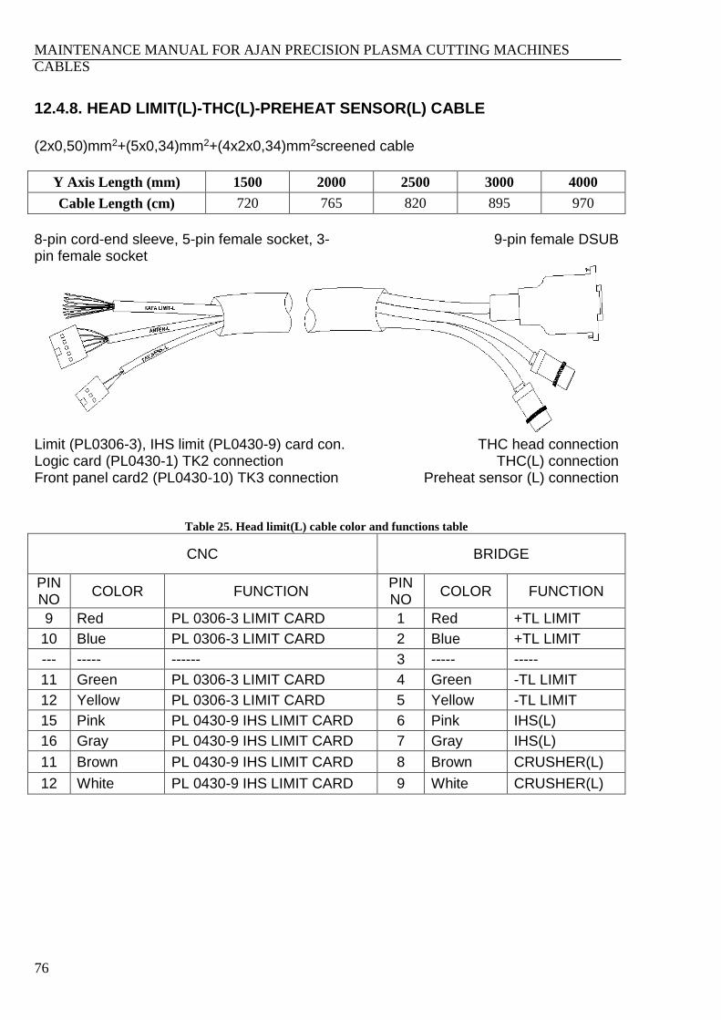
MAINTENANCE MANUAL FOR AJAN PRECISION PLASMA CUTTING MACHINES
CABLES
76
12.4.8. HEAD LIMIT(L)-THC(L)-PREHEAT SENSOR(L) CABLE
(2x0,50)mm2+(5x0,34)mm2+(4x2x0,34)mm2screened cable
Y Axis Length (mm) 1500 2000 2500 3000 4000
Cable Length (cm) 720 765 820 895 970
8-pin cord-end sleeve, 5-pin female socket, 3-pin female socket
9-pin female DSUB
Limit (PL0306-3), IHS limit (PL0430-9) card con. Logic card (PL0430-1) TK2 connection Front panel card2 (PL0430-10) TK3 connection
THC head connection THC(L) connection
Preheat sensor (L) connection
Table 25. Head limit(L) cable color and functions table
CNC BRIDGE
PIN NO
COLOR FUNCTION PIN NO
COLOR FUNCTION
9 Red PL 0306-3 LIMIT CARD 1 Red +TL LIMIT
10 Blue PL 0306-3 LIMIT CARD 2 Blue +TL LIMIT
--- ----- ------ 3 ----- -----
11 Green PL 0306-3 LIMIT CARD 4 Green -TL LIMIT
12 Yellow PL 0306-3 LIMIT CARD 5 Yellow -TL LIMIT
15 Pink PL 0430-9 IHS LIMIT CARD 6 Pink IHS(L)
16 Gray PL 0430-9 IHS LIMIT CARD 7 Gray IHS(L)
11 Brown PL 0430-9 IHS LIMIT CARD 8 Brown CRUSHER(L)
12 White PL 0430-9 IHS LIMIT CARD 9 White CRUSHER(L)
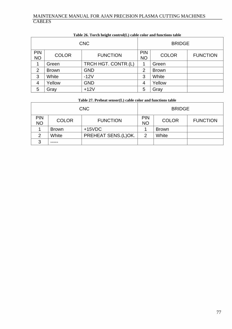
MAINTENANCE MANUAL FOR AJAN PRECISION PLASMA CUTTING MACHINES
CABLES
77
Table 26. Torch height control(L) cable color and functions table
CNC BRIDGE
PIN NO
COLOR FUNCTION PIN NO
COLOR FUNCTION
1 Green TRCH HGT. CONTR.(L) 1 Green
2 Brown GND 2 Brown
3 White -12V 3 White
4 Yellow GND 4 Yellow
5 Gray +12V 5 Gray
Table 27. Preheat sensor(L) cable color and functions table
CNC BRIDGE
PIN NO
COLOR FUNCTION PIN NO
COLOR FUNCTION
1 Brown +15VDC 1 Brown
2 White PREHEAT SENS.(L)OK. 2 White
3 -----
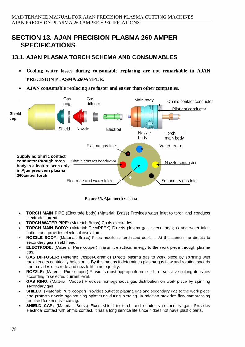
MAINTENANCE MANUAL FOR AJAN PRECISION PLASMA CUTTING MACHINES
AJAN PRECISION PLASMA 260 AMPER SPECIFICATIONS
78
SECTION 13. AJAN PRECISION PLASMA 260 AMPER SPECIFICATIONS
13.1. AJAN PLASMA TORCH SCHEMA AND CONSUMABLES
Cooling water losses during consumable replacing are not remarkable in AJAN
PRECISION PLASMA 260AMPER.
AJAN consumable replacing are faster and easier than other companies.
Figure 35. Ajan torch schema
TORCH MAIN PIPE (Electrode body) (Material: Brass) Provides water inlet to torch and conducts electrode current.
TORCH WATER PIPE: (Material: Brass) Cools electrodes.
TORCH MAIN BODY: (Material: TecaPEEK) Directs plasma gas, secondary gas and water inlet-outlets and provides electrical insulation.
NOZZLE BODY: (Material: Brass) Fixes nozzle to torch and cools it. At the same time directs to secondary gas shield head.
ELECTRODE: (Material: Pure copper) Transmit electrical energy to the work piece through plasma gas.
GAS DIFFUSER: (Material: Vespel-Ceramic) Directs plasma gas to work piece by spinning with radial end eccentrically holes on it. By this means it determines plasma gas flow and rotating speeds and provides electrode and nozzle lifetime equality.
NOZZLE: (Material: Pure copper) Provides most appropriate nozzle form sensitive cutting densities according to selected current level.
GAS RING: (Material: Vespel) Provides homogeneous gas distribution on work piece by spinning secondary gas.
SHIELD: (Material: Pure copper) Provides outlet to plasma gas and secondary gas to the work piece and protects nozzle against slag splattering during piercing. In addition provides flow compressing required for sensitive cutting.
SHIELD CAP: (Material: Brass) Fixes shield to torch and conducts secondary gas. Provides electrical contact with ohmic contact. It has a long service life since it does not have plastic parts.
Electrode and water inlet Secondary gas inlet
Nozzle conductor
Water return Plasma gas inlet
Ohmic contact conductor
Shield cap
Shield
Gas ring
Nozzle
Gas diffusor
Electrode Nozzle
body
Main body
Torch main body
Pilot arc conductor
Supplying ohmic contact conductor through torch body is a feature seen only in Ajan precısıon plasma
260amper torch
Ohmic contact conductor

MAINTENANCE MANUAL FOR AJAN PRECISION PLASMA CUTTING MACHINES
AJAN PRECISION PLASMA 260 AMPER SPECIFICATIONS
79

MAINTENANCE MANUAL FOR AJAN PRECISION PLASMA CUTTING MACHINES
AJAN PRECISION PLASMA 260 AMPER SPECIFICATIONS
80
13.2. AJAN PRECISION PLASMA SYSTEM CONSUMABLES LIFETIMES AND GAS CONSUMPTIONS
AJAN minimizes the consumption material cost added to total cutting cost by means of
consumption material techniques it developed. For this reason, AJAN provides the following cost
table to its customers. Total value of consumption materials plus gas and electric costs constitute
%2-%5 of the 1 kg sheet cost that will be cut on condition of changing according to shape number
and sheet thicknesses. AJAN Consumption Materials Lifetime and Quality tables and gas flows
have been given in below figure.
Figure 36. Ajan PRECISION PLASMA 260AMPER Electrode and Nozzle required life time chart
Figure 37. Ajan precısıon plasma 130A mper Electrode and Nozzle required life time chart
Table 28. Ajan precısıon plasma 260 amper plasma generator gas flow rates
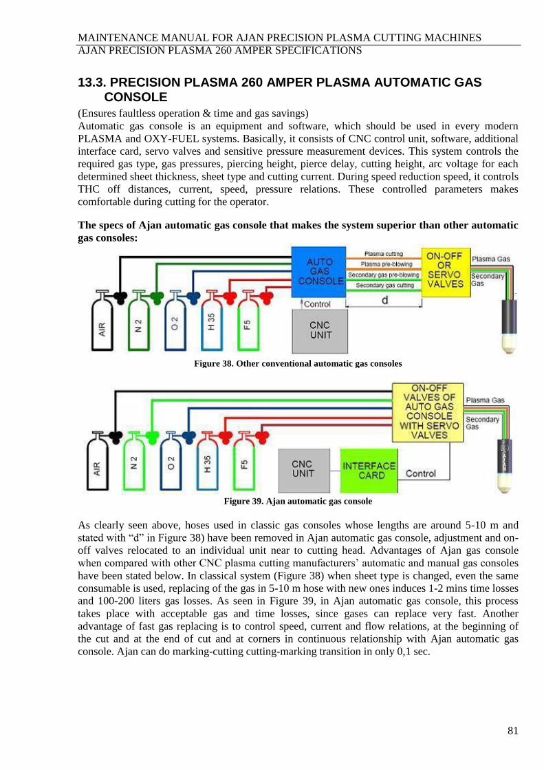
MAINTENANCE MANUAL FOR AJAN PRECISION PLASMA CUTTING MACHINES
AJAN PRECISION PLASMA 260 AMPER SPECIFICATIONS
81
13.3. PRECISION PLASMA 260 AMPER PLASMA AUTOMATIC GAS CONSOLE
(Ensures faultless operation & time and gas savings)
Automatic gas console is an equipment and software, which should be used in every modern
PLASMA and OXY-FUEL systems. Basically, it consists of CNC control unit, software, additional
interface card, servo valves and sensitive pressure measurement devices. This system controls the
required gas type, gas pressures, piercing height, pierce delay, cutting height, arc voltage for each
determined sheet thickness, sheet type and cutting current. During speed reduction speed, it controls
THC off distances, current, speed, pressure relations. These controlled parameters makes
comfortable during cutting for the operator.
The specs of Ajan automatic gas console that makes the system superior than other automatic
gas consoles:
Figure 38. Other conventional automatic gas consoles
Figure 39. Ajan automatic gas console
As clearly seen above, hoses used in classic gas consoles whose lengths are around 5-10 m and
stated with “d” in Figure 38) have been removed in Ajan automatic gas console, adjustment and on-
off valves relocated to an individual unit near to cutting head. Advantages of Ajan gas console
when compared with other CNC plasma cutting manufacturers’ automatic and manual gas consoles
have been stated below. In classical system (Figure 38) when sheet type is changed, even the same
consumable is used, replacing of the gas in 5-10 m hose with new ones induces 1-2 mins time losses
and 100-200 liters gas losses. As seen in Figure 39, in Ajan automatic gas console, this process
takes place with acceptable gas and time losses, since gases can replace very fast. Another
advantage of fast gas replacing is to control speed, current and flow relations, at the beginning of
the cut and at the end of cut and at corners in continuous relationship with Ajan automatic gas
console. Ajan can do marking-cutting cutting-marking transition in only 0,1 sec.

MAINTENANCE MANUAL FOR AJAN PRECISION PLASMA CUTTING MACHINES
AJAN PRECISION PLASMA 260 AMPER SPECIFICATIONS
82
13.4. ALL INCLUSIVE CONTROL PANEL
(Dryer, Ventilation, Generator, Jet Filter)
Plasma cutting systems comprise of following tools and equipments.
GENERATOR
VENTILATION
JET FILTER
All these elements need electricity. Required electrical energy and gas distribution responsibility is
left to the customer in conventional assemblies. Customer will call electric and pneumatic
technicians believing that they are good for these assemblies. Final picture possibly will disturb
both customer and machine supplier. For precluding this:
A central panel that includes everything needed for Ajan Plasma and OXY-FUEL cutting systems is
provided and above mentioned 4 units are fed through this panel. Mutual accusations between
customer and manufacturer are eliminated. Since advanced plasma cutting technologies have been
used in the world in recent years, solving such installation problems by machine supplier will be far
better and economic. Because a company having 35 years of experiences like Ajan should know all
kinds of problem about these systems better than other individuals.
Cable and hose lengths are calculated separately for all sizes and categories are used in Ajan All
Inclusive system. By this means there shall be no cable and hoses crawling around that could cause
to accidents.
Figure 40. New conception Ajan all inclusive plasma cutting system
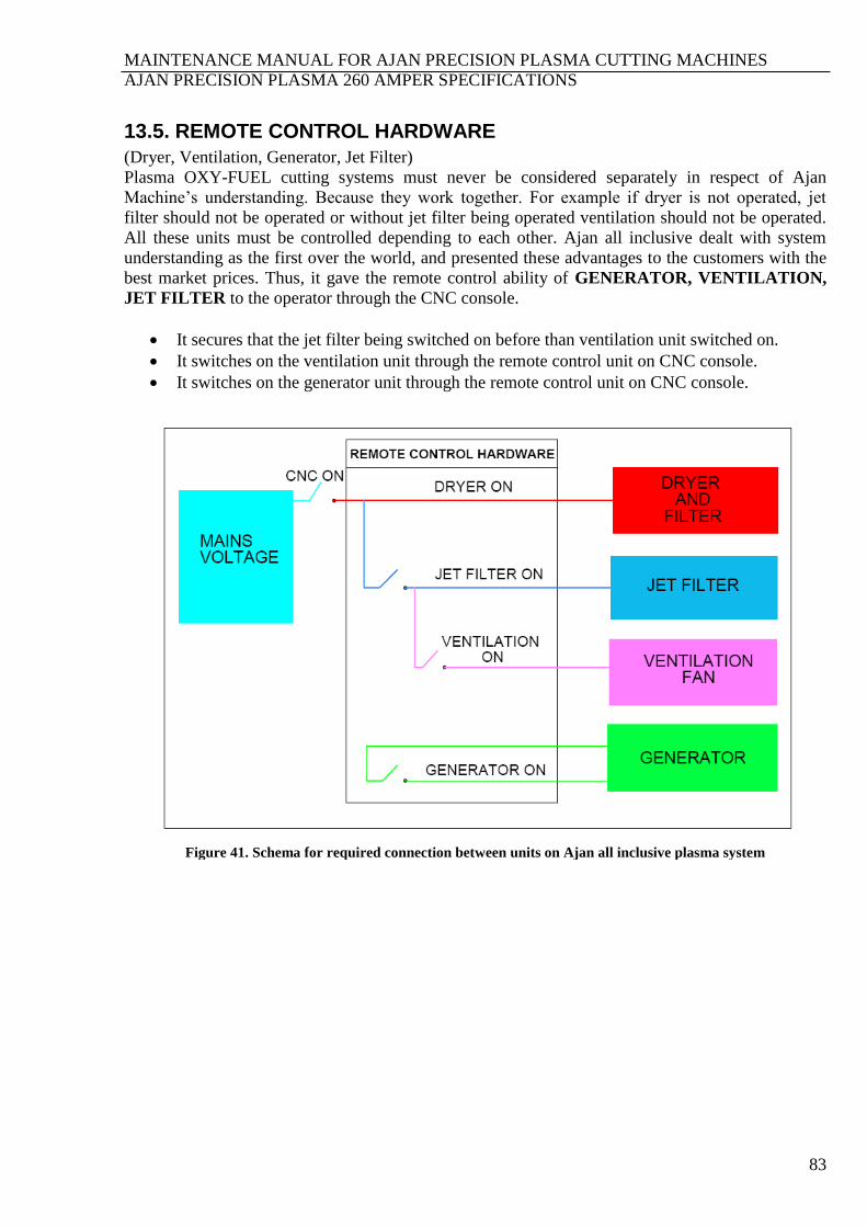
MAINTENANCE MANUAL FOR AJAN PRECISION PLASMA CUTTING MACHINES
AJAN PRECISION PLASMA 260 AMPER SPECIFICATIONS
83
13.5. REMOTE CONTROL HARDWARE
(Dryer, Ventilation, Generator, Jet Filter)
Plasma OXY-FUEL cutting systems must never be considered separately in respect of Ajan
Machine’s understanding. Because they work together. For example if dryer is not operated, jet
filter should not be operated or without jet filter being operated ventilation should not be operated.
All these units must be controlled depending to each other. Ajan all inclusive dealt with system
understanding as the first over the world, and presented these advantages to the customers with the
best market prices. Thus, it gave the remote control ability of GENERATOR, VENTILATION,
JET FILTER to the operator through the CNC console.
It secures that the jet filter being switched on before than ventilation unit switched on.
It switches on the ventilation unit through the remote control unit on CNC console.
It switches on the generator unit through the remote control unit on CNC console.
Figure 41. Schema for required connection between units on Ajan all inclusive plasma system
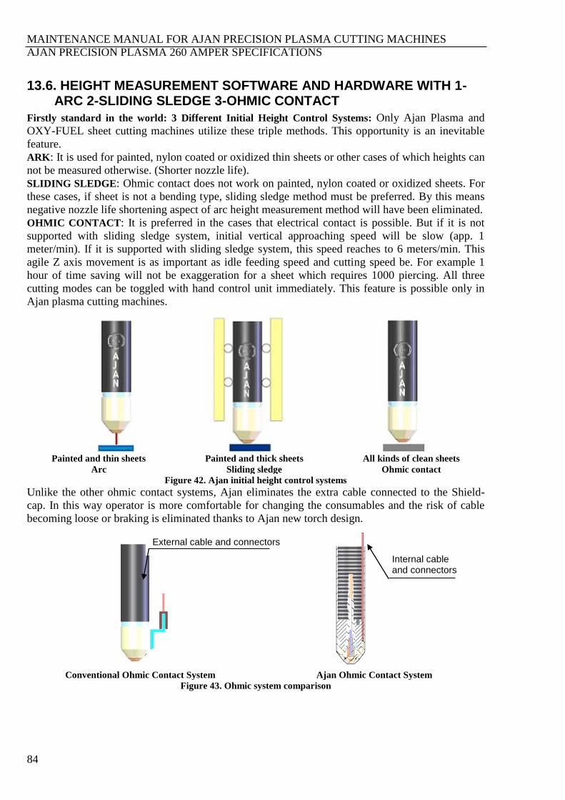
MAINTENANCE MANUAL FOR AJAN PRECISION PLASMA CUTTING MACHINES
AJAN PRECISION PLASMA 260 AMPER SPECIFICATIONS
84
13.6. HEIGHT MEASUREMENT SOFTWARE AND HARDWARE WITH 1-ARC 2-SLIDING SLEDGE 3-OHMIC CONTACT
Firstly standard in the world: 3 Different Initial Height Control Systems: Only Ajan Plasma and
OXY-FUEL sheet cutting machines utilize these triple methods. This opportunity is an inevitable
feature.
ARK: It is used for painted, nylon coated or oxidized thin sheets or other cases of which heights can
not be measured otherwise. (Shorter nozzle life).
SLIDING SLEDGE: Ohmic contact does not work on painted, nylon coated or oxidized sheets. For
these cases, if sheet is not a bending type, sliding sledge method must be preferred. By this means
negative nozzle life shortening aspect of arc height measurement method will have been eliminated.
OHMIC CONTACT: It is preferred in the cases that electrical contact is possible. But if it is not
supported with sliding sledge system, initial vertical approaching speed will be slow (app. 1
meter/min). If it is supported with sliding sledge system, this speed reaches to 6 meters/min. This
agile Z axis movement is as important as idle feeding speed and cutting speed be. For example 1
hour of time saving will not be exaggeration for a sheet which requires 1000 piercing. All three
cutting modes can be toggled with hand control unit immediately. This feature is possible only in
Ajan plasma cutting machines.
Painted and thin sheets Painted and thick sheets All kinds of clean sheets
Arc Sliding sledge Ohmic contact
Figure 42. Ajan initial height control systems
Unlike the other ohmic contact systems, Ajan eliminates the extra cable connected to the Shield-
cap. In this way operator is more comfortable for changing the consumables and the risk of cable
becoming loose or braking is eliminated thanks to Ajan new torch design.
Conventional Ohmic Contact System Ajan Ohmic Contact System
Figure 43. Ohmic system comparison
External cable and connectors
Internal cable and connectors
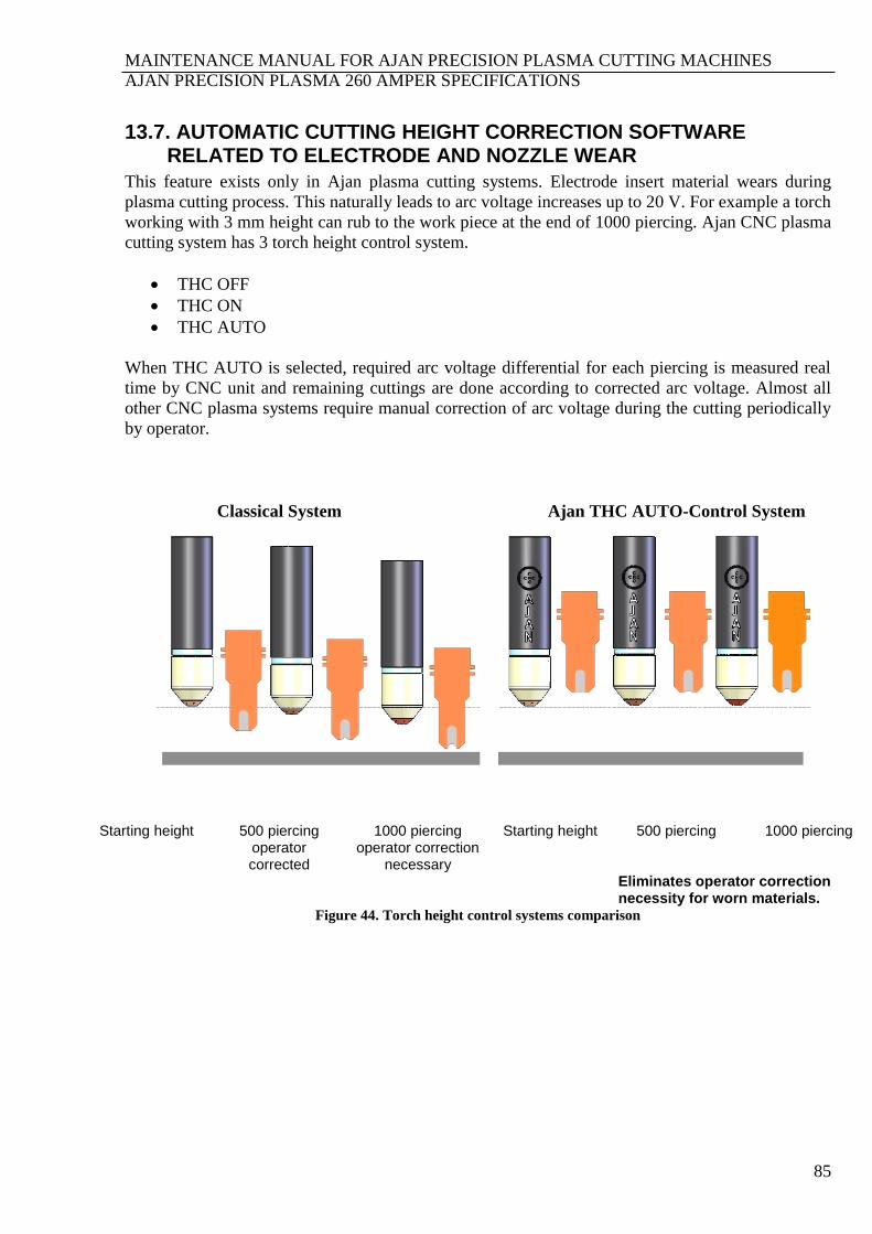
MAINTENANCE MANUAL FOR AJAN PRECISION PLASMA CUTTING MACHINES
AJAN PRECISION PLASMA 260 AMPER SPECIFICATIONS
85
13.7. AUTOMATIC CUTTING HEIGHT CORRECTION SOFTWARE RELATED TO ELECTRODE AND NOZZLE WEAR
This feature exists only in Ajan plasma cutting systems. Electrode insert material wears during
plasma cutting process. This naturally leads to arc voltage increases up to 20 V. For example a torch
working with 3 mm height can rub to the work piece at the end of 1000 piercing. Ajan CNC plasma
cutting system has 3 torch height control system.
THC OFF
THC ON
THC AUTO
When THC AUTO is selected, required arc voltage differential for each piercing is measured real
time by CNC unit and remaining cuttings are done according to corrected arc voltage. Almost all
other CNC plasma systems require manual correction of arc voltage during the cutting periodically
by operator.
Classical System Ajan THC AUTO-Control System
Starting height 500 piercing
operator corrected
1000 piercing operator correction
necessary
Starting height 500 piercing 1000 piercing
Eliminates operator correction necessity for worn materials.
Figure 44. Torch height control systems comparison
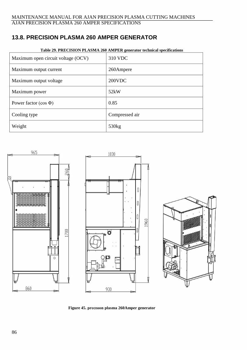
MAINTENANCE MANUAL FOR AJAN PRECISION PLASMA CUTTING MACHINES
AJAN PRECISION PLASMA 260 AMPER SPECIFICATIONS
86
13.8. PRECISION PLASMA 260 AMPER GENERATOR
Table 29. PRECISION PLASMA 260 AMPER generator technical specifications
Maximum open circuit voltage (OCV) 310 VDC
Maximum output current 260Ampere
Maximum output voltage 200VDC
Maximum power 52kW
Power factor (cos Φ) 0.85
Cooling type Compressed air
Weight 530kg
Figure 45. precısıon plasma 260Amper generator
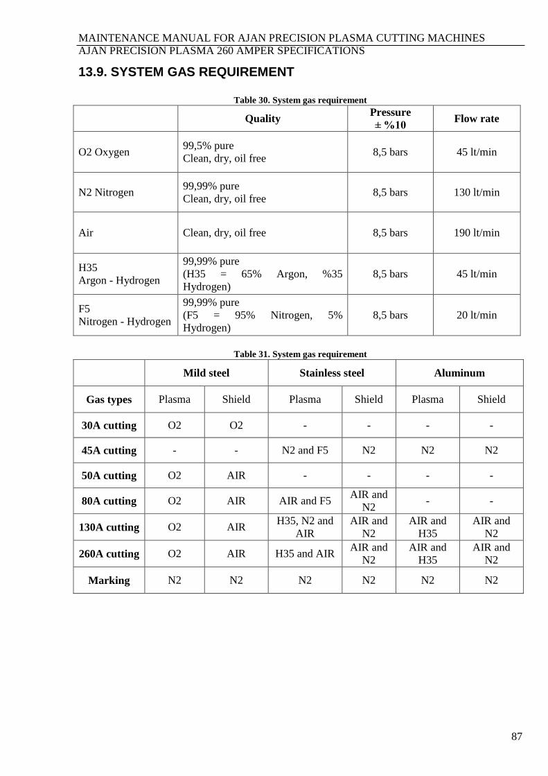
MAINTENANCE MANUAL FOR AJAN PRECISION PLASMA CUTTING MACHINES
AJAN PRECISION PLASMA 260 AMPER SPECIFICATIONS
87
13.9. SYSTEM GAS REQUIREMENT
Table 30. System gas requirement
Quality Pressure
± %10 Flow rate
O2 Oxygen 99,5% pure
Clean, dry, oil free 8,5 bars 45 lt/min
N2 Nitrogen 99,99% pure
Clean, dry, oil free 8,5 bars 130 lt/min
Air Clean, dry, oil free 8,5 bars 190 lt/min
H35
Argon - Hydrogen
99,99% pure
(H35 = 65% Argon, %35
Hydrogen)
8,5 bars 45 lt/min
F5
Nitrogen - Hydrogen
99,99% pure
(F5 = 95% Nitrogen, 5%
Hydrogen)
8,5 bars 20 lt/min
Table 31. System gas requirement
Mild steel Stainless steel Aluminum
Gas types Plasma Shield Plasma Shield Plasma Shield
30A cutting O2 O2 - - - -
45A cutting - - N2 and F5 N2 N2 N2
50A cutting O2 AIR - - - -
80A cutting O2 AIR AIR and F5 AIR and
N2 - -
130A cutting O2 AIR H35, N2 and
AIR
AIR and
N2
AIR and
H35
AIR and
N2
260A cutting O2 AIR H35 and AIR AIR and
N2
AIR and
H35
AIR and
N2
Marking N2 N2 N2 N2 N2 N2

MAINTENANCE MANUAL FOR AJAN PRECISION PLASMA CUTTING MACHINES
CUTTING CHARTS
88
SECTION 14. CUTTING CHARTS Table 32. Mild steel, O2 Plasma/O2 Shield, 30A cutting chart
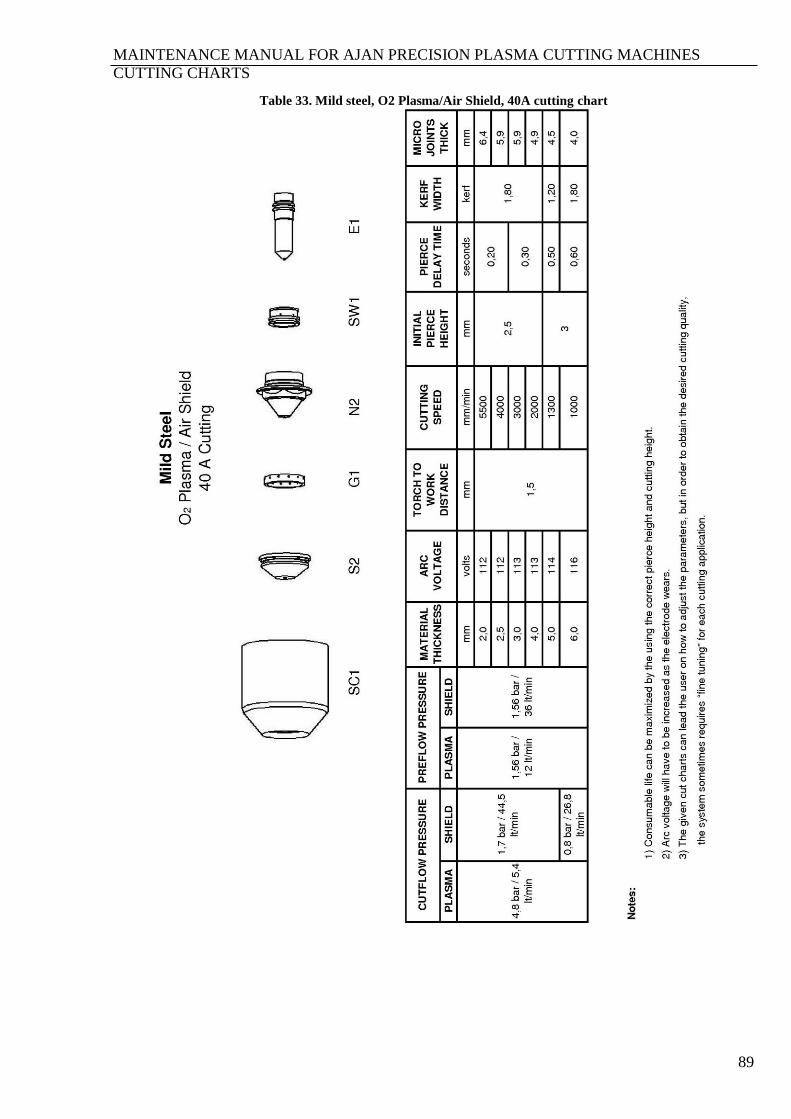
MAINTENANCE MANUAL FOR AJAN PRECISION PLASMA CUTTING MACHINES
CUTTING CHARTS
89
Table 33. Mild steel, O2 Plasma/Air Shield, 40A cutting chart
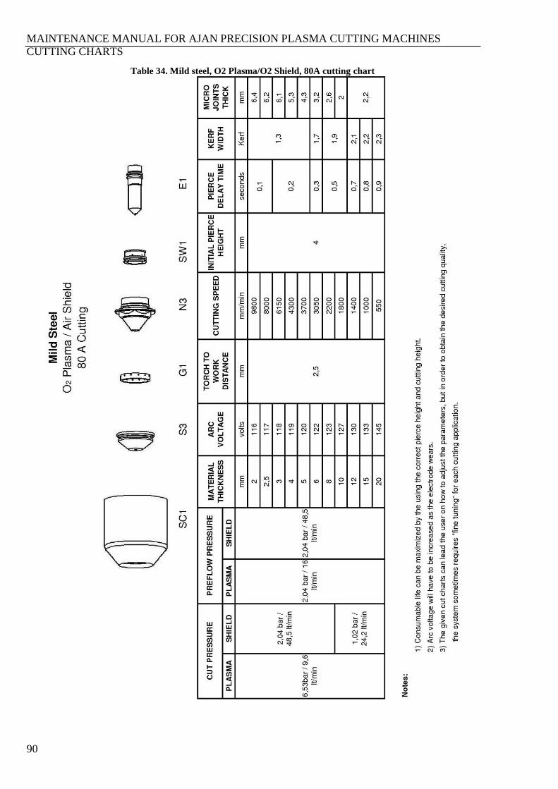
MAINTENANCE MANUAL FOR AJAN PRECISION PLASMA CUTTING MACHINES
CUTTING CHARTS
90
Table 34. Mild steel, O2 Plasma/O2 Shield, 80A cutting chart
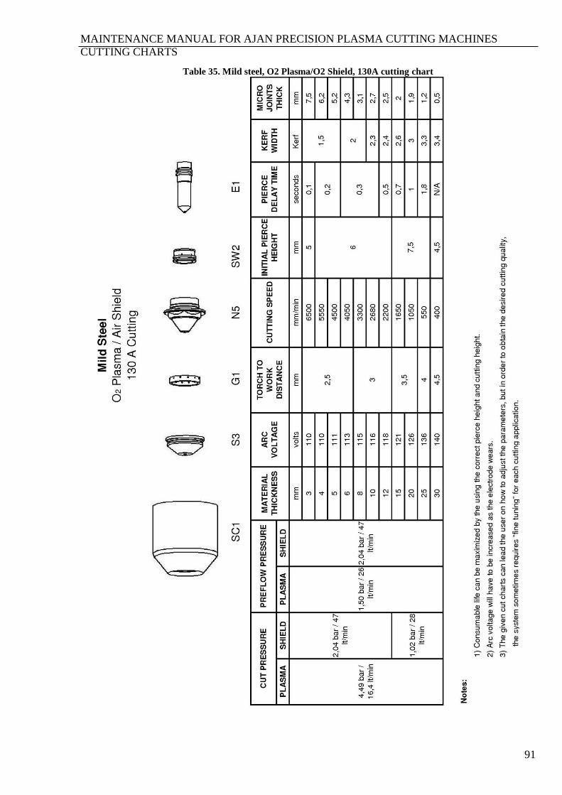
MAINTENANCE MANUAL FOR AJAN PRECISION PLASMA CUTTING MACHINES
CUTTING CHARTS
91
Table 35. Mild steel, O2 Plasma/O2 Shield, 130A cutting chart
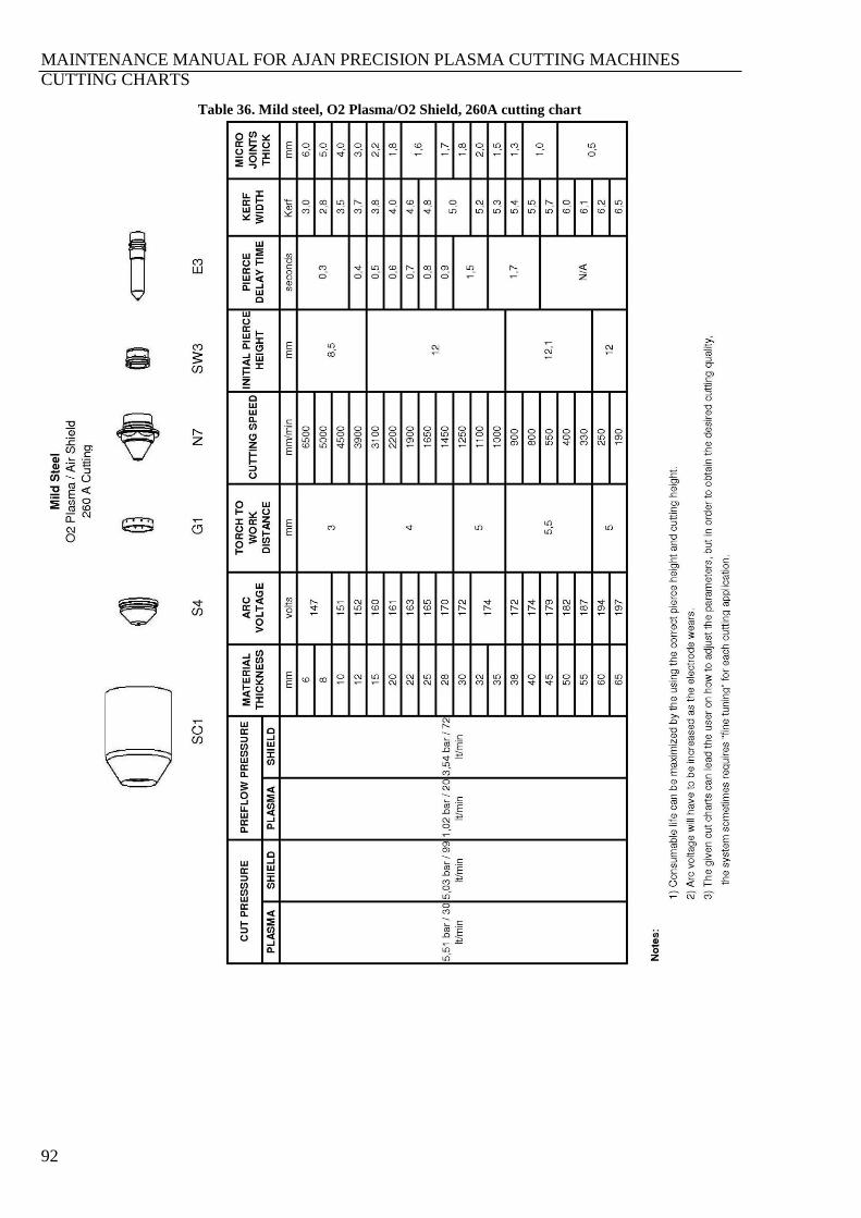
MAINTENANCE MANUAL FOR AJAN PRECISION PLASMA CUTTING MACHINES
CUTTING CHARTS
92
Table 36. Mild steel, O2 Plasma/O2 Shield, 260A cutting chart
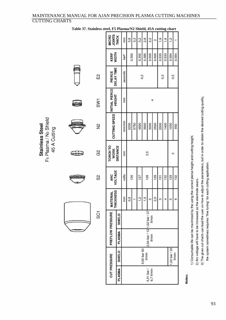
MAINTENANCE MANUAL FOR AJAN PRECISION PLASMA CUTTING MACHINES
CUTTING CHARTS
93
Table 37. Stainless steel, F5 Plasma/N2 Shield, 45A cutting chart
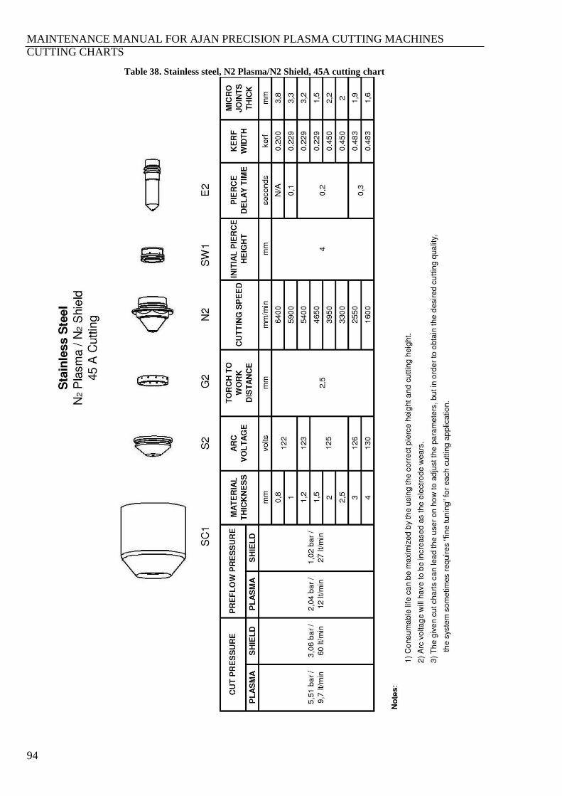
MAINTENANCE MANUAL FOR AJAN PRECISION PLASMA CUTTING MACHINES
CUTTING CHARTS
94
Table 38. Stainless steel, N2 Plasma/N2 Shield, 45A cutting chart

MAINTENANCE MANUAL FOR AJAN PRECISION PLASMA CUTTING MACHINES
CUTTING CHARTS
95
Table 39. Stainless steel, Air Plasma/Air Shield, 80A cutting chart
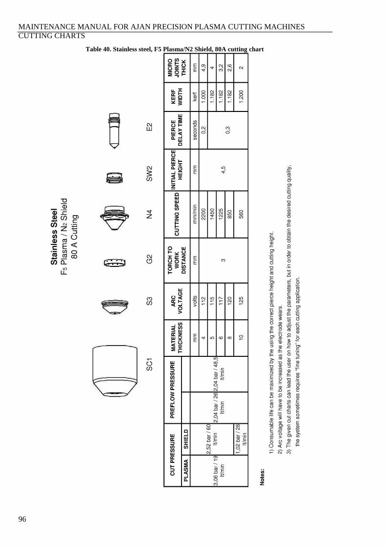
MAINTENANCE MANUAL FOR AJAN PRECISION PLASMA CUTTING MACHINES
CUTTING CHARTS
96
Table 40. Stainless steel, F5 Plasma/N2 Shield, 80A cutting chart
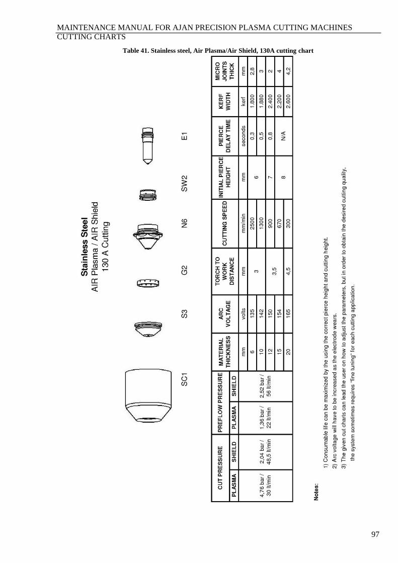
MAINTENANCE MANUAL FOR AJAN PRECISION PLASMA CUTTING MACHINES
CUTTING CHARTS
97
Table 41. Stainless steel, Air Plasma/Air Shield, 130A cutting chart
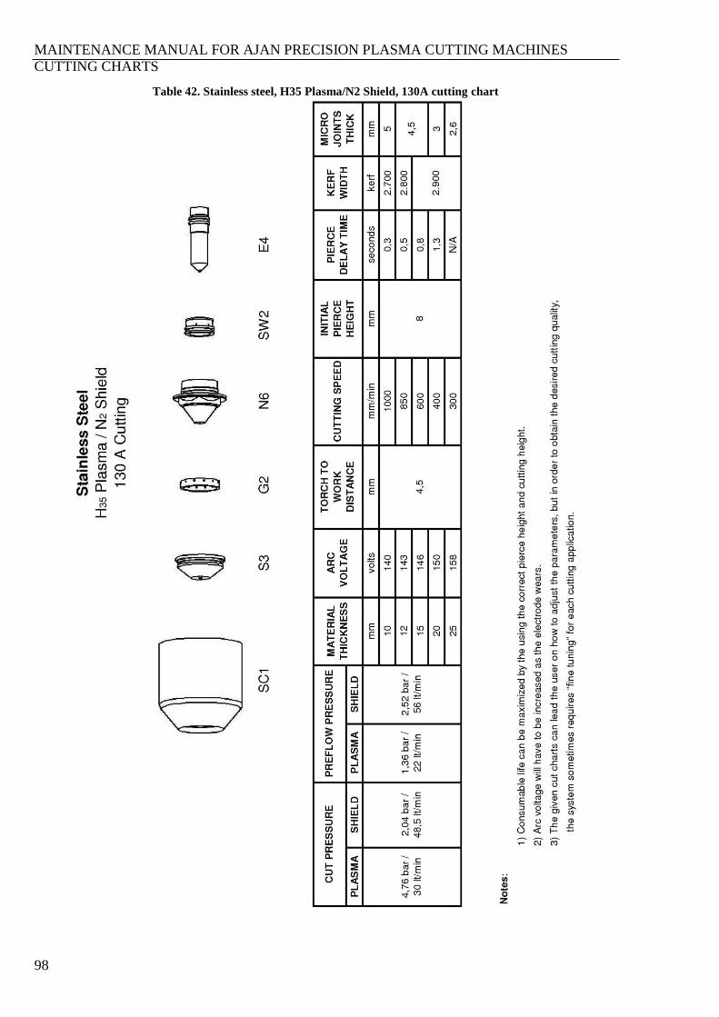
MAINTENANCE MANUAL FOR AJAN PRECISION PLASMA CUTTING MACHINES
CUTTING CHARTS
98
Table 42. Stainless steel, H35 Plasma/N2 Shield, 130A cutting chart
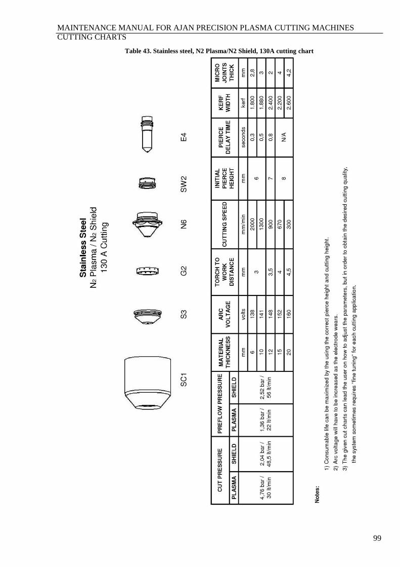
MAINTENANCE MANUAL FOR AJAN PRECISION PLASMA CUTTING MACHINES
CUTTING CHARTS
99
Table 43. Stainless steel, N2 Plasma/N2 Shield, 130A cutting chart
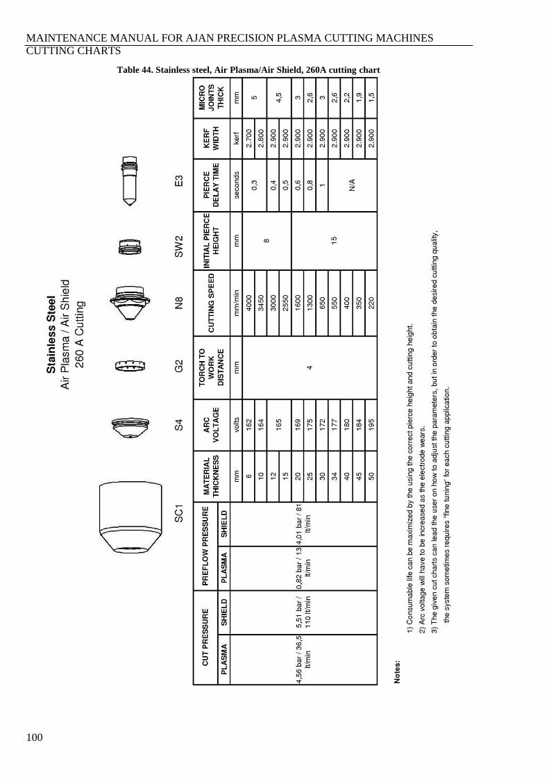
MAINTENANCE MANUAL FOR AJAN PRECISION PLASMA CUTTING MACHINES
CUTTING CHARTS
100
Table 44. Stainless steel, Air Plasma/Air Shield, 260A cutting chart
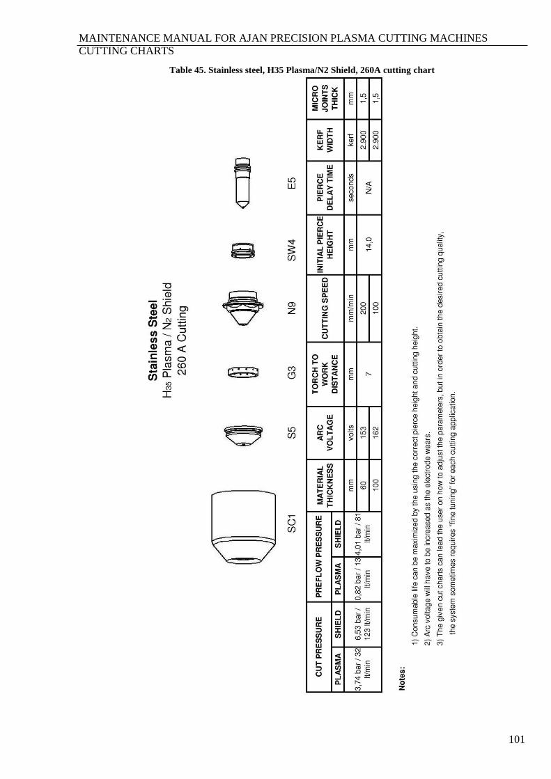
MAINTENANCE MANUAL FOR AJAN PRECISION PLASMA CUTTING MACHINES
CUTTING CHARTS
101
Table 45. Stainless steel, H35 Plasma/N2 Shield, 260A cutting chart
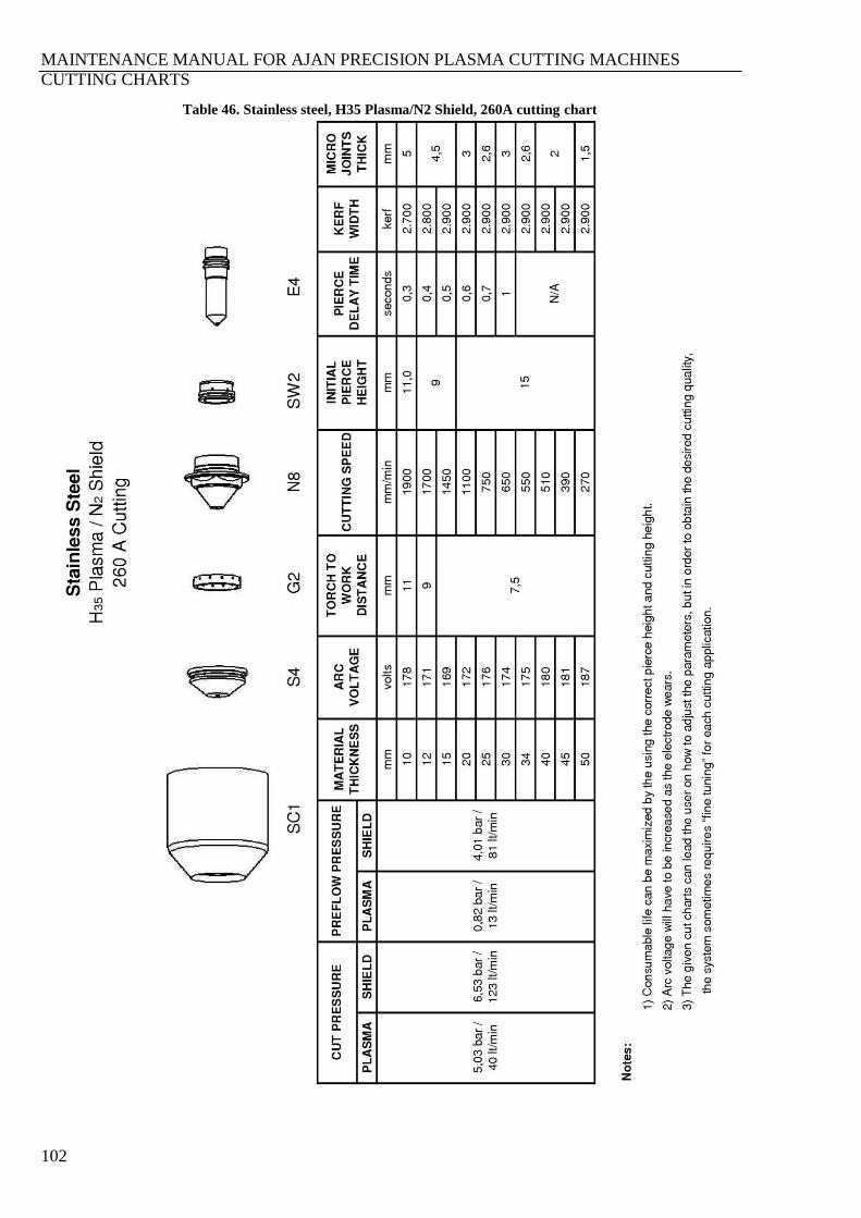
MAINTENANCE MANUAL FOR AJAN PRECISION PLASMA CUTTING MACHINES
CUTTING CHARTS
102
Table 46. Stainless steel, H35 Plasma/N2 Shield, 260A cutting chart
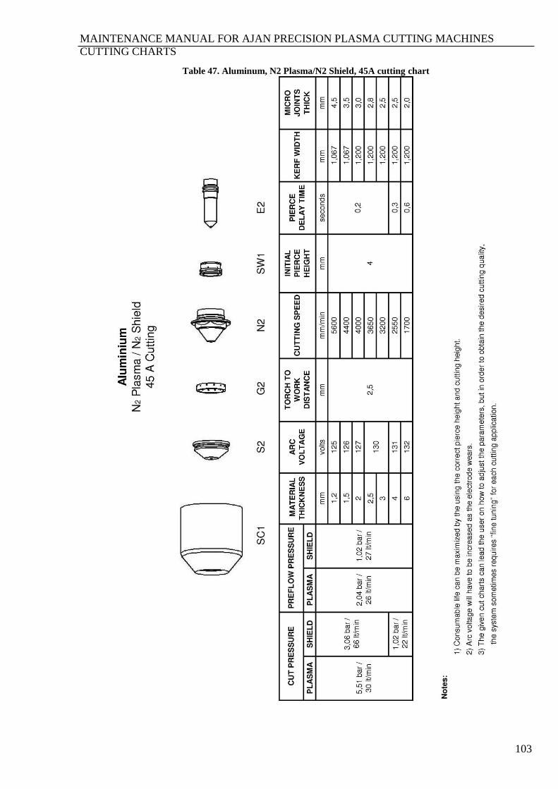
MAINTENANCE MANUAL FOR AJAN PRECISION PLASMA CUTTING MACHINES
CUTTING CHARTS
103
Table 47. Aluminum, N2 Plasma/N2 Shield, 45A cutting chart

MAINTENANCE MANUAL FOR AJAN PRECISION PLASMA CUTTING MACHINES
CUTTING CHARTS
104
Table 48. Aluminum, Air Plasma/Air Shield, 130A cutting chart
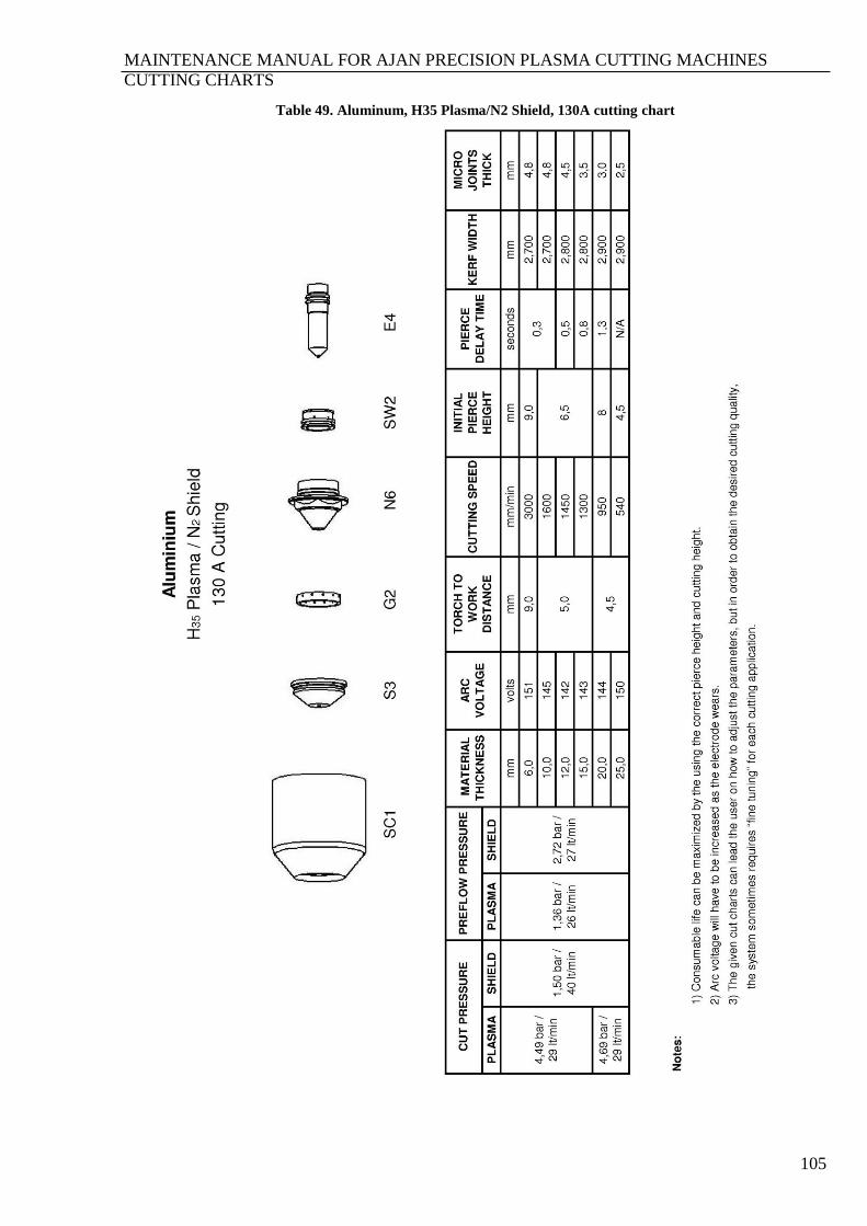
MAINTENANCE MANUAL FOR AJAN PRECISION PLASMA CUTTING MACHINES
CUTTING CHARTS
105
Table 49. Aluminum, H35 Plasma/N2 Shield, 130A cutting chart
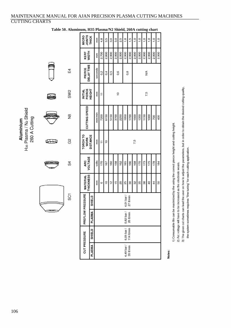
MAINTENANCE MANUAL FOR AJAN PRECISION PLASMA CUTTING MACHINES
CUTTING CHARTS
106
Table 50. Aluminum, H35 Plasma/N2 Shield, 260A cutting chart
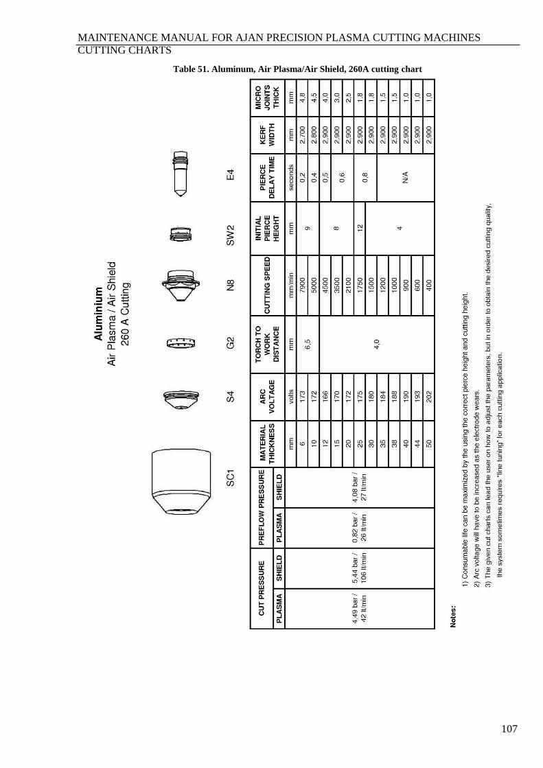
MAINTENANCE MANUAL FOR AJAN PRECISION PLASMA CUTTING MACHINES
CUTTING CHARTS
107
Table 51. Aluminum, Air Plasma/Air Shield, 260A cutting chart
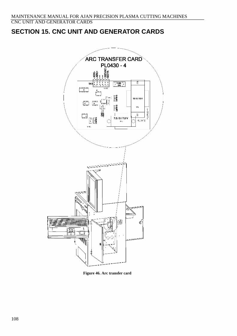
MAINTENANCE MANUAL FOR AJAN PRECISION PLASMA CUTTING MACHINES
CNC UNIT AND GENERATOR CARDS
108
SECTION 15. CNC UNIT AND GENERATOR CARDS
Figure 46. Arc transfer card
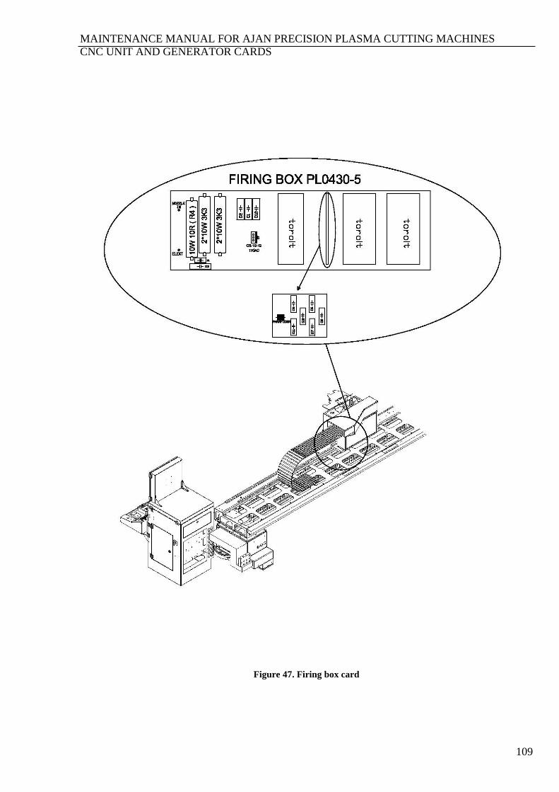
MAINTENANCE MANUAL FOR AJAN PRECISION PLASMA CUTTING MACHINES
CNC UNIT AND GENERATOR CARDS
109
Figure 47. Firing box card
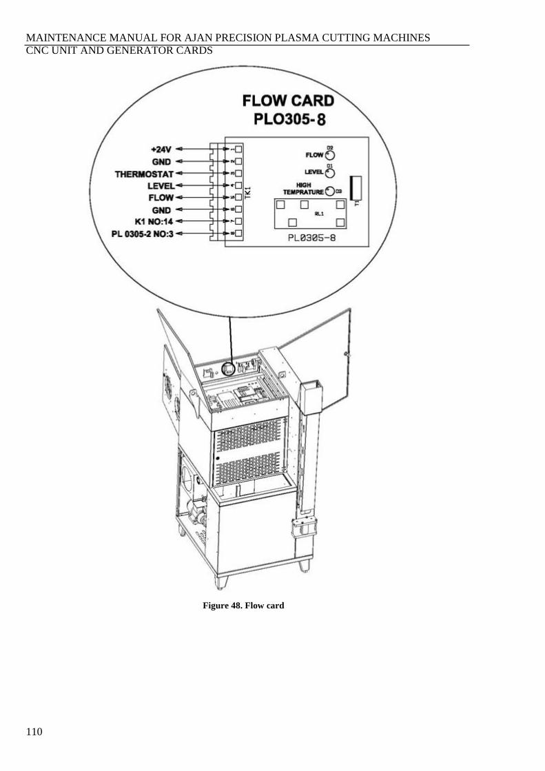
MAINTENANCE MANUAL FOR AJAN PRECISION PLASMA CUTTING MACHINES
CNC UNIT AND GENERATOR CARDS
110
Figure 48. Flow card

MAINTENANCE MANUAL FOR AJAN PRECISION PLASMA CUTTING MACHINES
CNC UNIT AND GENERATOR CARDS
111
Figure 49. IGBT driver card
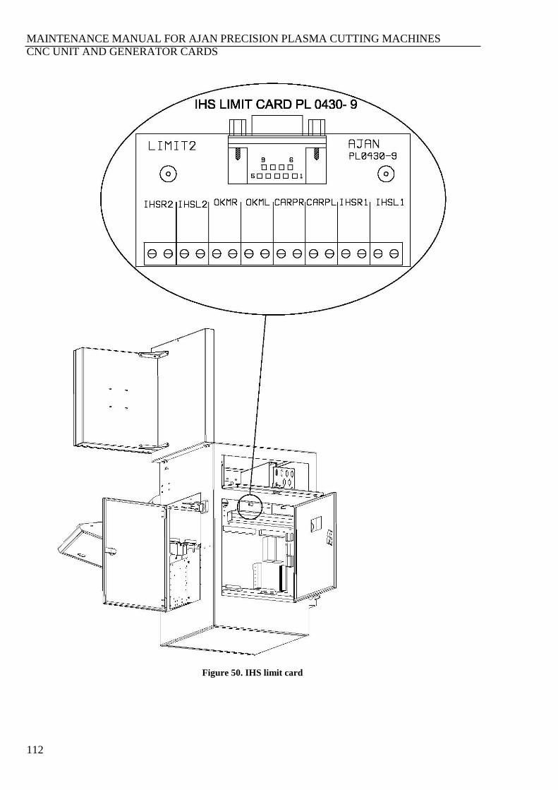
MAINTENANCE MANUAL FOR AJAN PRECISION PLASMA CUTTING MACHINES
CNC UNIT AND GENERATOR CARDS
112
Figure 50. IHS limit card
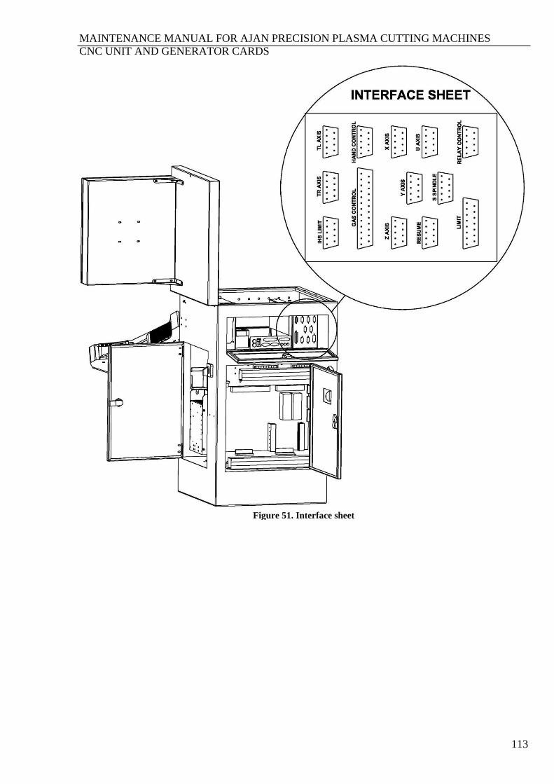
MAINTENANCE MANUAL FOR AJAN PRECISION PLASMA CUTTING MACHINES
CNC UNIT AND GENERATOR CARDS
113
Figure 51. Interface sheet

MAINTENANCE MANUAL FOR AJAN PRECISION PLASMA CUTTING MACHINES
CNC UNIT AND GENERATOR CARDS
114
Figure 52. Precısıon plasma generator control card
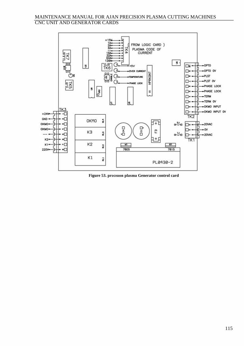
MAINTENANCE MANUAL FOR AJAN PRECISION PLASMA CUTTING MACHINES
CNC UNIT AND GENERATOR CARDS
115
Figure 53. precısıon plasma Generator control card

MAINTENANCE MANUAL FOR AJAN PRECISION PLASMA CUTTING MACHINES
CNC UNIT AND GENERATOR CARDS
116
Figure 54. Condenser card
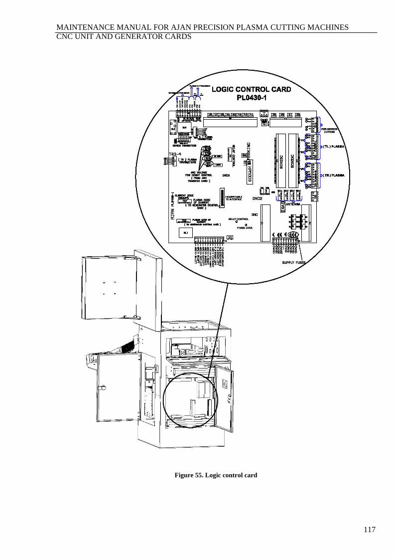
MAINTENANCE MANUAL FOR AJAN PRECISION PLASMA CUTTING MACHINES
CNC UNIT AND GENERATOR CARDS
117
Figure 55. Logic control card
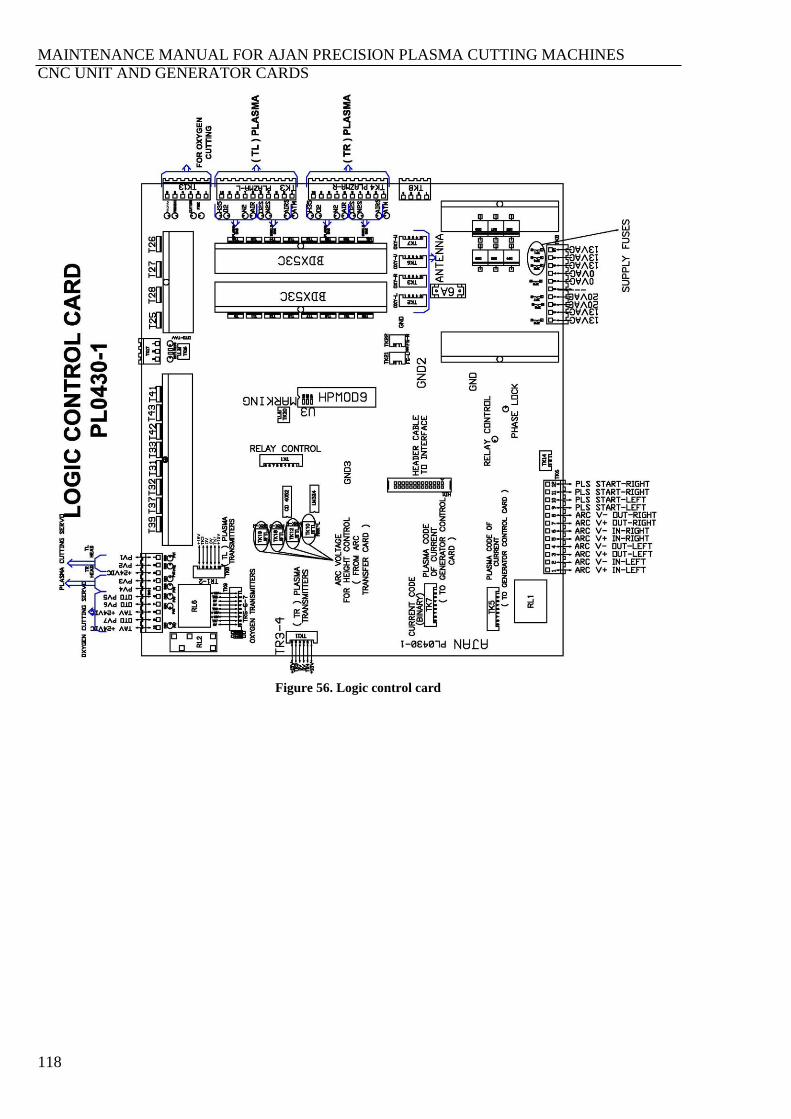
MAINTENANCE MANUAL FOR AJAN PRECISION PLASMA CUTTING MACHINES
CNC UNIT AND GENERATOR CARDS
118
Figure 56. Logic control card

MAINTENANCE MANUAL FOR AJAN PRECISION PLASMA CUTTING MACHINES
CNC UNIT AND GENERATOR CARDS
119
Figure 57. Front panel card

MAINTENANCE MANUAL FOR AJAN PRECISION PLASMA CUTTING MACHINES
CNC UNIT AND GENERATOR CARDS
120
Figure 58. Power card
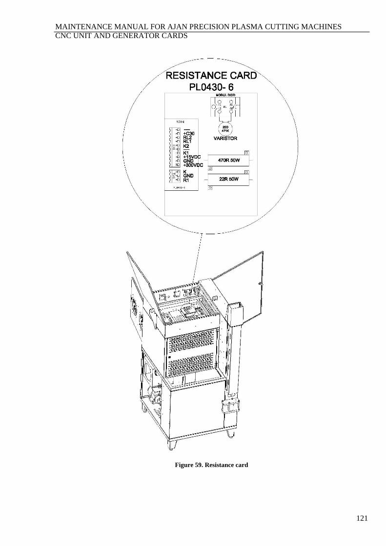
MAINTENANCE MANUAL FOR AJAN PRECISION PLASMA CUTTING MACHINES
CNC UNIT AND GENERATOR CARDS
121
Figure 59. Resistance card

MAINTENANCE MANUAL FOR AJAN PRECISION PLASMA CUTTING MACHINES
CNC UNIT AND GENERATOR CARDS
122
Figure 60. Start circuit
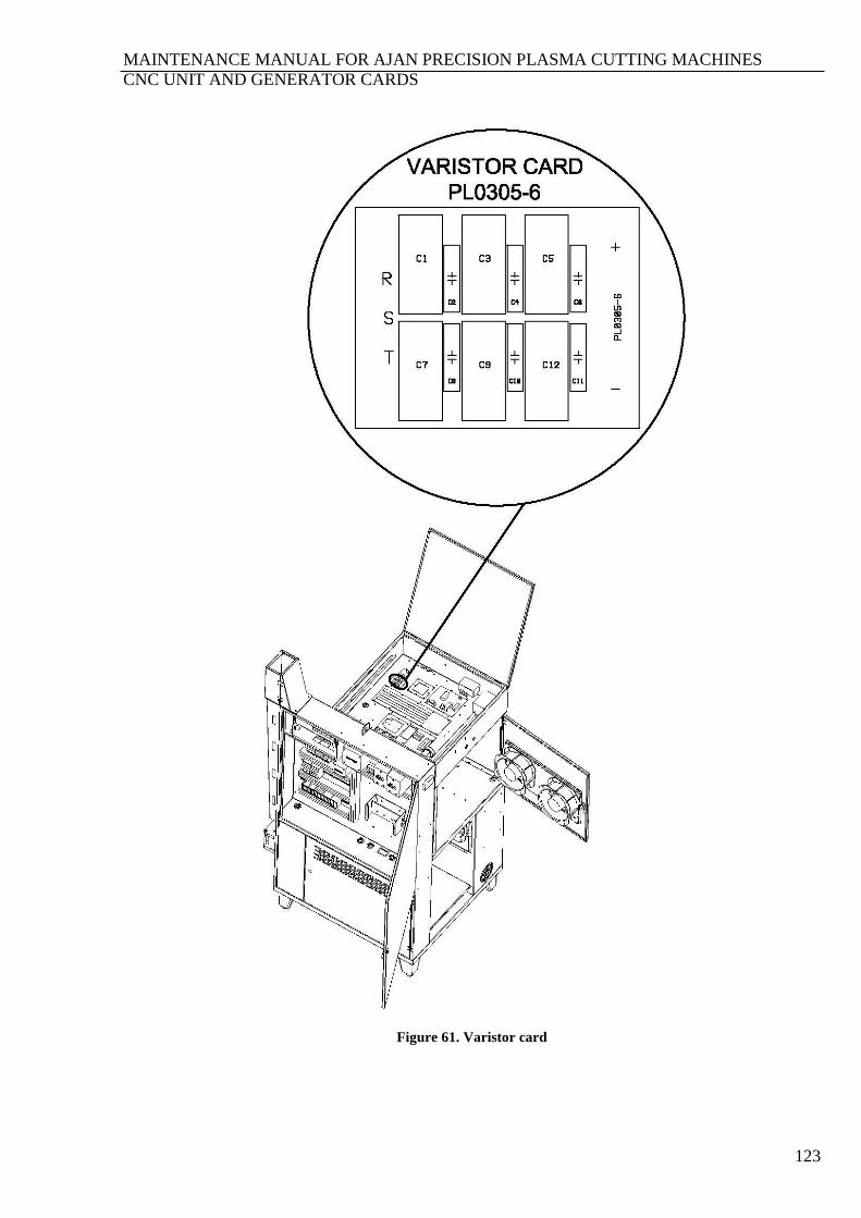
MAINTENANCE MANUAL FOR AJAN PRECISION PLASMA CUTTING MACHINES
CNC UNIT AND GENERATOR CARDS
123
Figure 61. Varistor card

MAINTENANCE MANUAL FOR AJAN PRECISION PLASMA CUTTING MACHINES
CONNECTION SCHEMAS
124
SECTION 16. CONNECTION SCHEMAS
Figure 62. Plasma plate

MAINTENANCE MANUAL FOR AJAN PRECISION PLASMA CUTTING MACHINES
CONNECTION SCHEMAS
125
Figure 63. Plasma plate hose gas connection schema
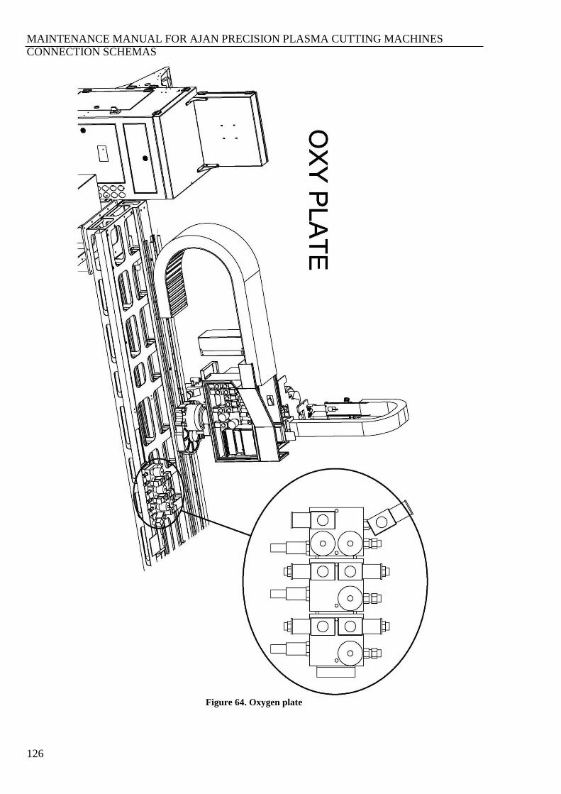
MAINTENANCE MANUAL FOR AJAN PRECISION PLASMA CUTTING MACHINES
CONNECTION SCHEMAS
126
Figure 64. Oxygen plate
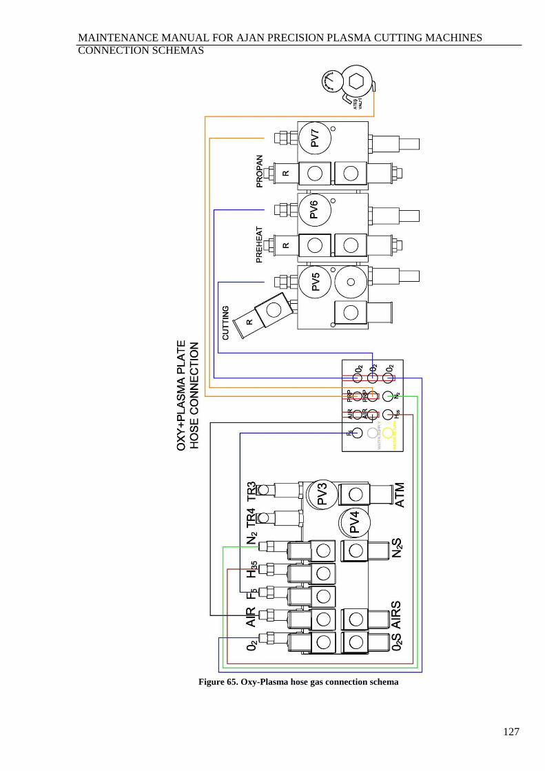
MAINTENANCE MANUAL FOR AJAN PRECISION PLASMA CUTTING MACHINES
CONNECTION SCHEMAS
127
Figure 65. Oxy-Plasma hose gas connection schema
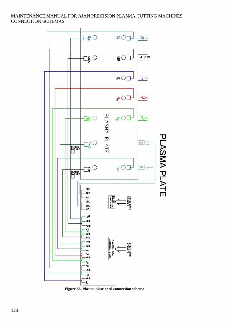
MAINTENANCE MANUAL FOR AJAN PRECISION PLASMA CUTTING MACHINES
CONNECTION SCHEMAS
128
Figure 66. Plasma plate card connection schema
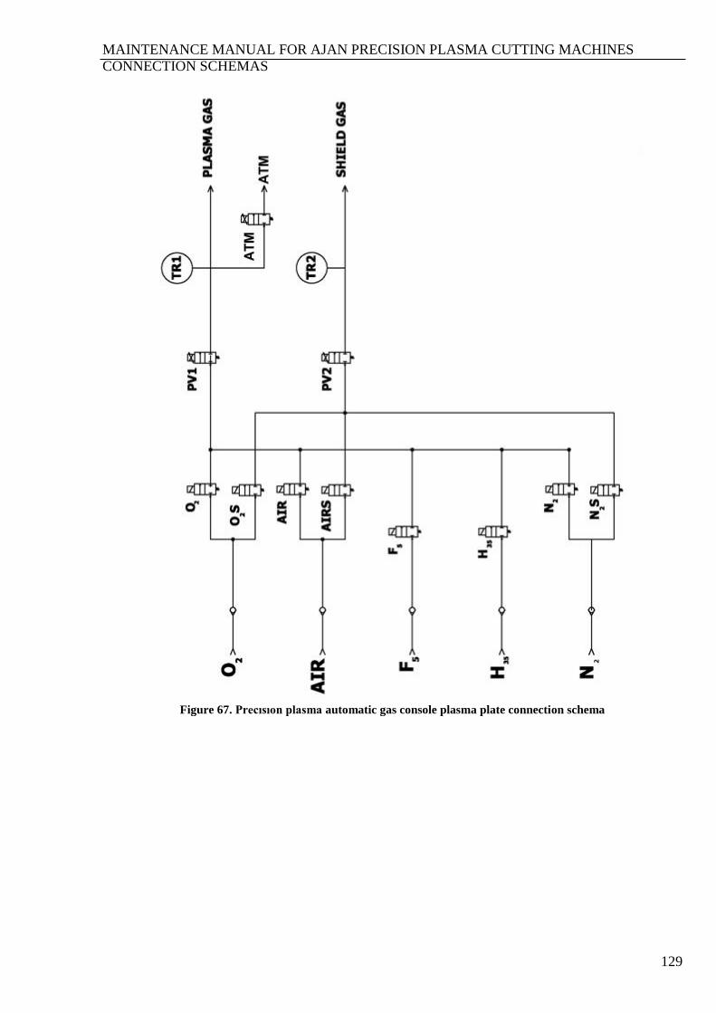
MAINTENANCE MANUAL FOR AJAN PRECISION PLASMA CUTTING MACHINES
CONNECTION SCHEMAS
129
Figure 67. Precısıon plasma automatic gas console plasma plate connection schema
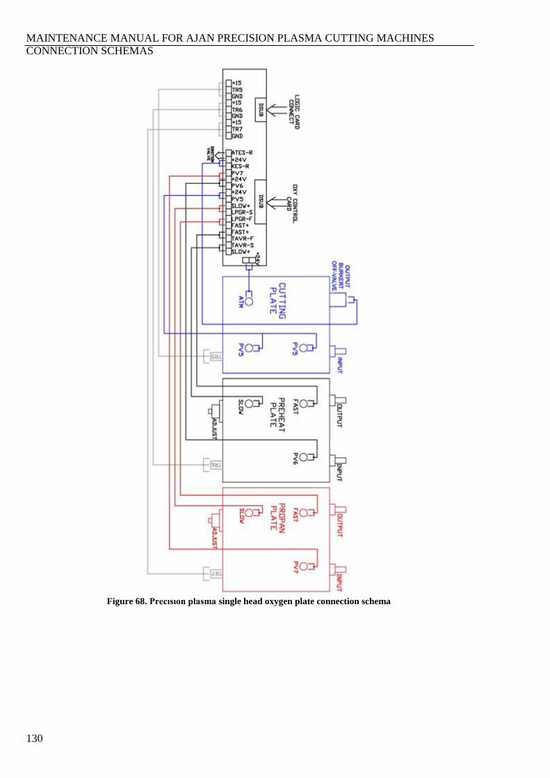
MAINTENANCE MANUAL FOR AJAN PRECISION PLASMA CUTTING MACHINES
CONNECTION SCHEMAS
130
Figure 68. Precısıon plasma single head oxygen plate connection schema
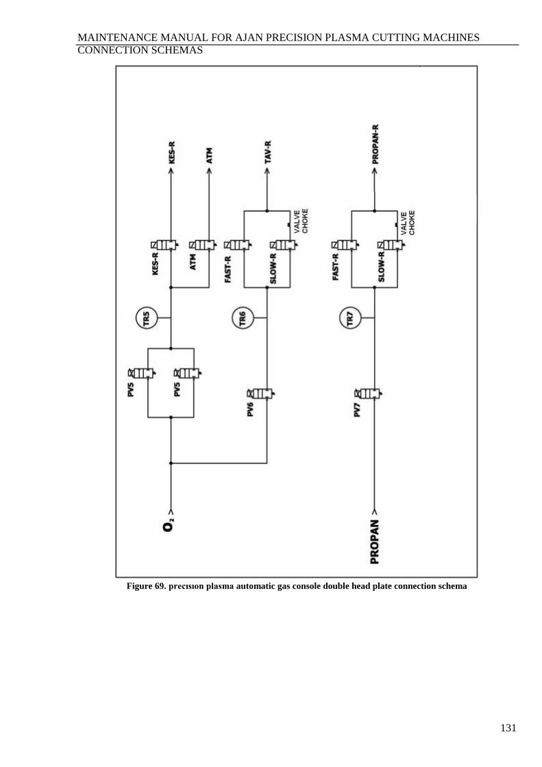
MAINTENANCE MANUAL FOR AJAN PRECISION PLASMA CUTTING MACHINES
CONNECTION SCHEMAS
131
Figure 69. precısıon plasma automatic gas console double head plate connection schema
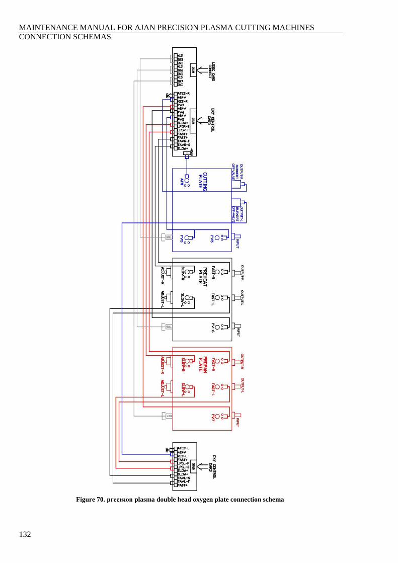
MAINTENANCE MANUAL FOR AJAN PRECISION PLASMA CUTTING MACHINES
CONNECTION SCHEMAS
132
Figure 70. precısıon plasma double head oxygen plate connection schema
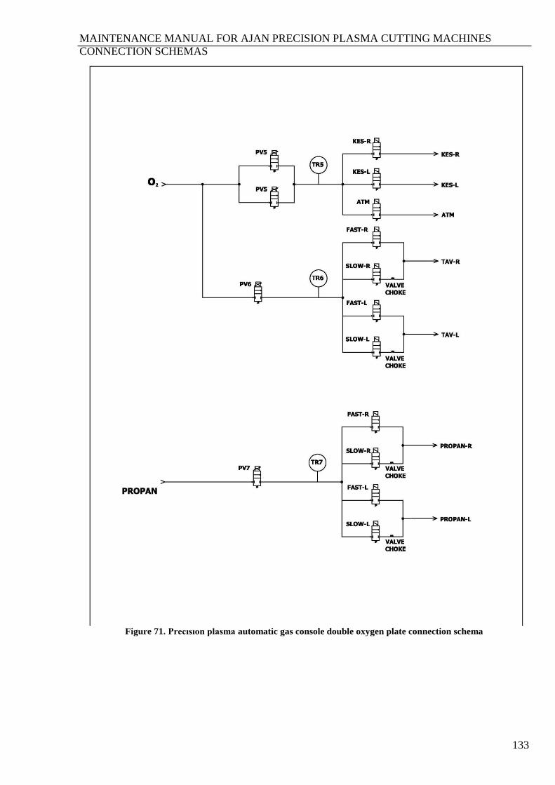
MAINTENANCE MANUAL FOR AJAN PRECISION PLASMA CUTTING MACHINES
CONNECTION SCHEMAS
133
Figure 71. Precısıon plasma automatic gas console double oxygen plate connection schema

MAINTENANCE MANUAL FOR AJAN PRECISION PLASMA CUTTING MACHINES
CONNECTION SCHEMAS
134
Figure 72. Precısıon plasma four head oxygen plate connection schema

MAINTENANCE MANUAL FOR AJAN PRECISION PLASMA CUTTING MACHINES
CONNECTION SCHEMAS
135
Figure 73. Precısıon plasma triple head plate connection schema
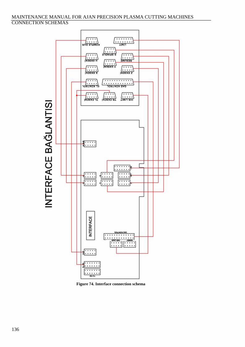
MAINTENANCE MANUAL FOR AJAN PRECISION PLASMA CUTTING MACHINES
CONNECTION SCHEMAS
136
Figure 74. Interface connection schema
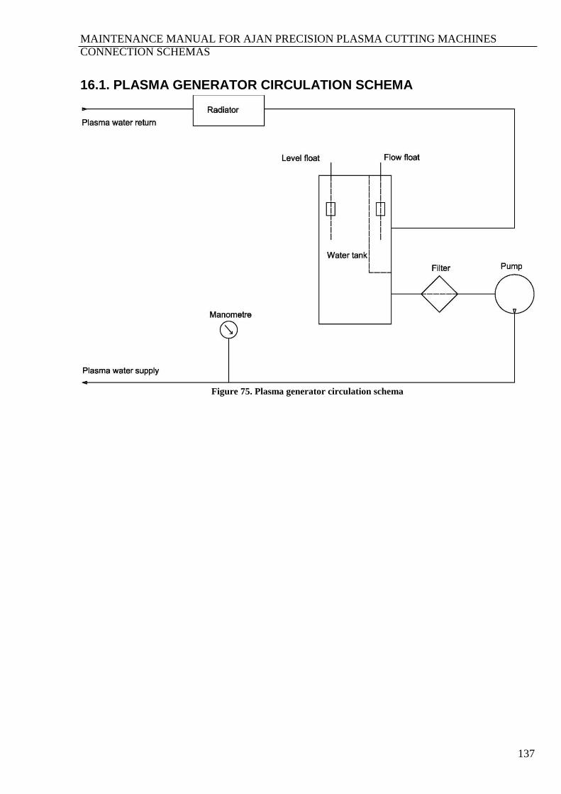
MAINTENANCE MANUAL FOR AJAN PRECISION PLASMA CUTTING MACHINES
CONNECTION SCHEMAS
137
16.1. PLASMA GENERATOR CIRCULATION SCHEMA
Figure 75. Plasma generator circulation schema
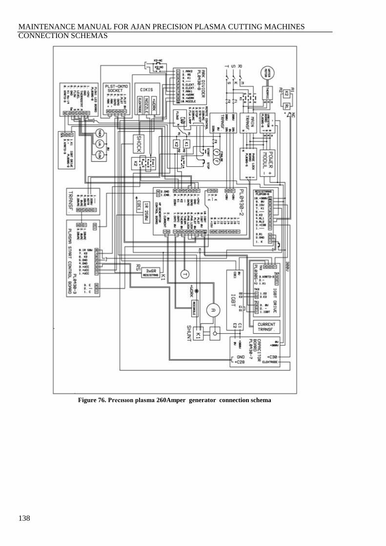
MAINTENANCE MANUAL FOR AJAN PRECISION PLASMA CUTTING MACHINES
CONNECTION SCHEMAS
138
Figure 76. Precısıon plasma 260Amper generator connection schema
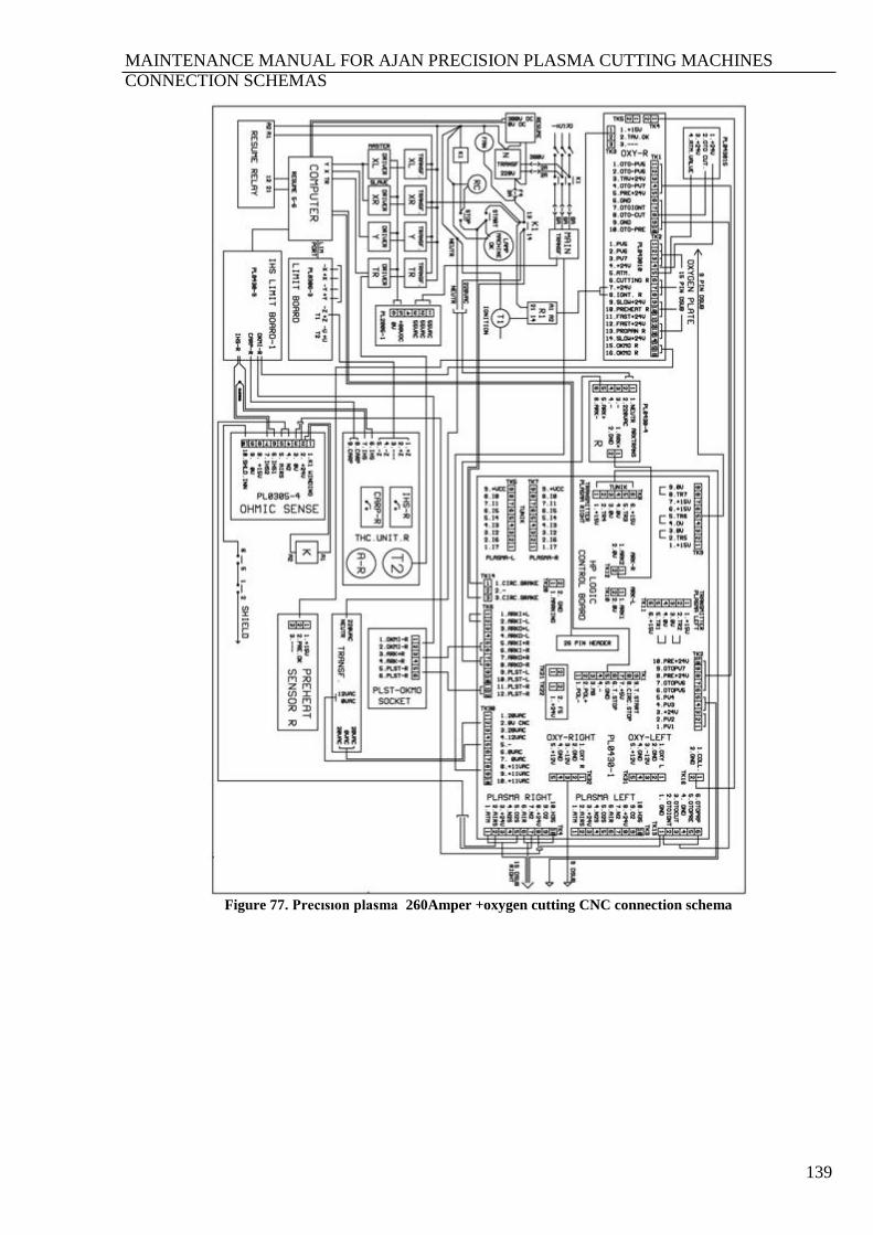
MAINTENANCE MANUAL FOR AJAN PRECISION PLASMA CUTTING MACHINES
CONNECTION SCHEMAS
139
Figure 77. Precısıon plasma 260Amper +oxygen cutting CNC connection schema
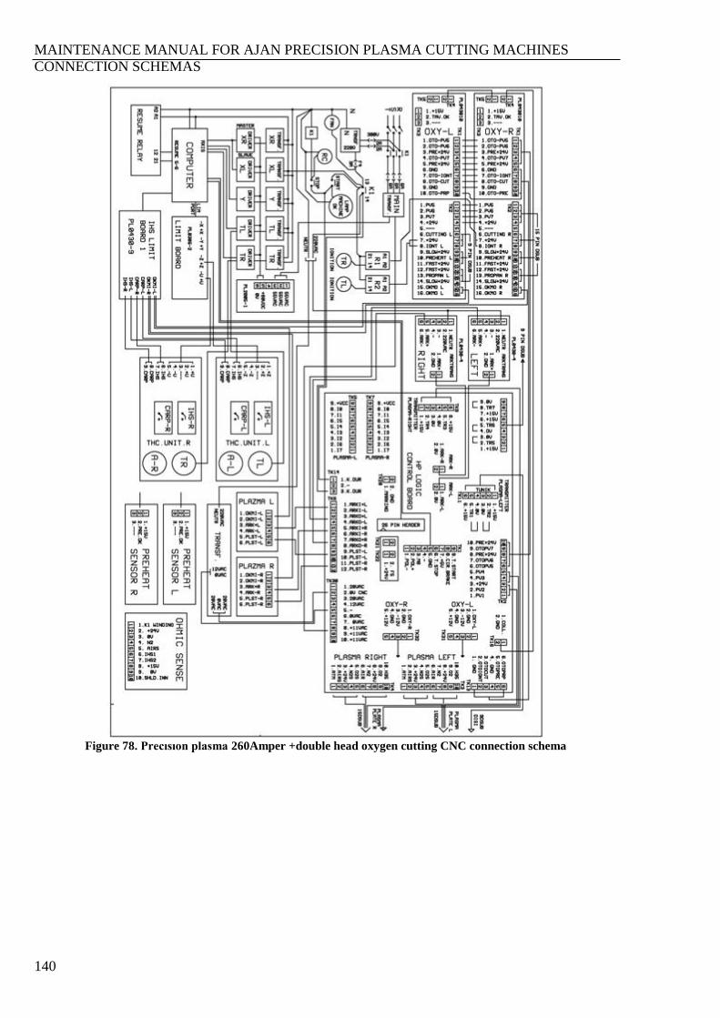
MAINTENANCE MANUAL FOR AJAN PRECISION PLASMA CUTTING MACHINES
CONNECTION SCHEMAS
140
Figure 78. Precısıon plasma 260Amper +double head oxygen cutting CNC connection schema
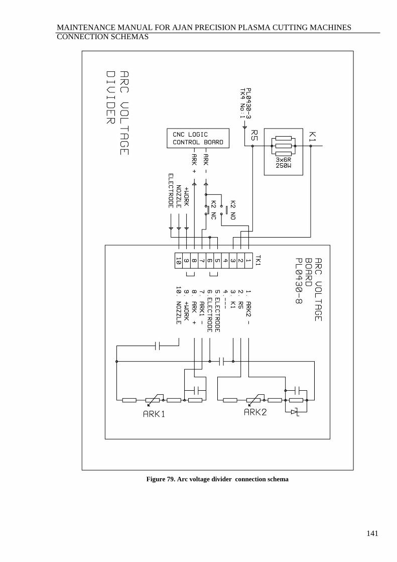
MAINTENANCE MANUAL FOR AJAN PRECISION PLASMA CUTTING MACHINES
CONNECTION SCHEMAS
141
Figure 79. Arc voltage divider connection schema
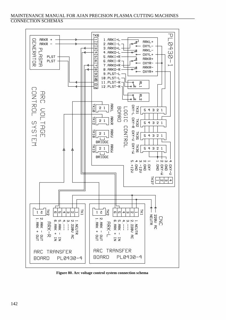
MAINTENANCE MANUAL FOR AJAN PRECISION PLASMA CUTTING MACHINES
CONNECTION SCHEMAS
142
Figure 80. Arc voltage control system connection schema
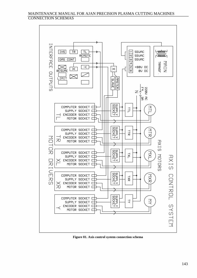
MAINTENANCE MANUAL FOR AJAN PRECISION PLASMA CUTTING MACHINES
CONNECTION SCHEMAS
143
Figure 81. Axis control system connection schema

MAINTENANCE MANUAL FOR AJAN PRECISION PLASMA CUTTING MACHINES
CONNECTION SCHEMAS
144
Figure 82. Precısıon plasma generator control card connection schema
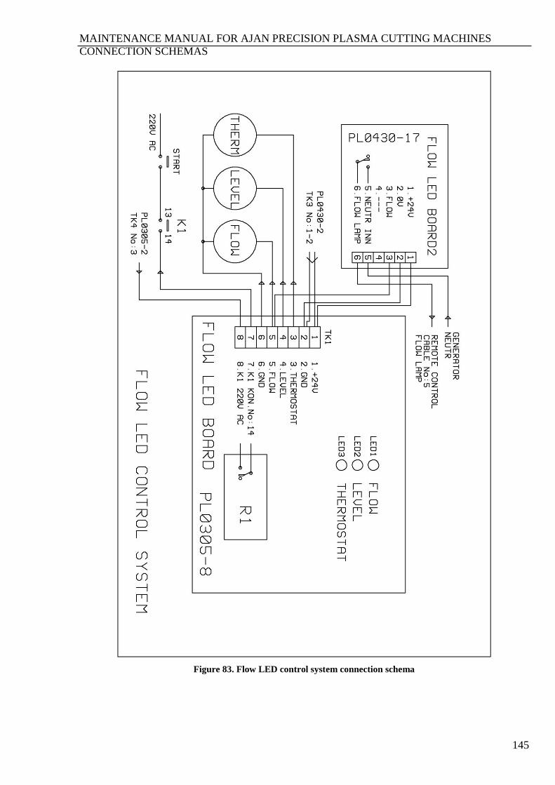
MAINTENANCE MANUAL FOR AJAN PRECISION PLASMA CUTTING MACHINES
CONNECTION SCHEMAS
145
Figure 83. Flow LED control system connection schema
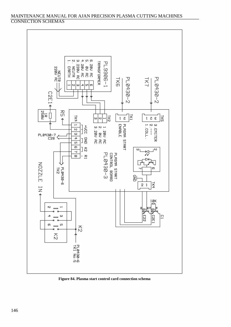
MAINTENANCE MANUAL FOR AJAN PRECISION PLASMA CUTTING MACHINES
CONNECTION SCHEMAS
146
Figure 84. Plasma start control card connection schema
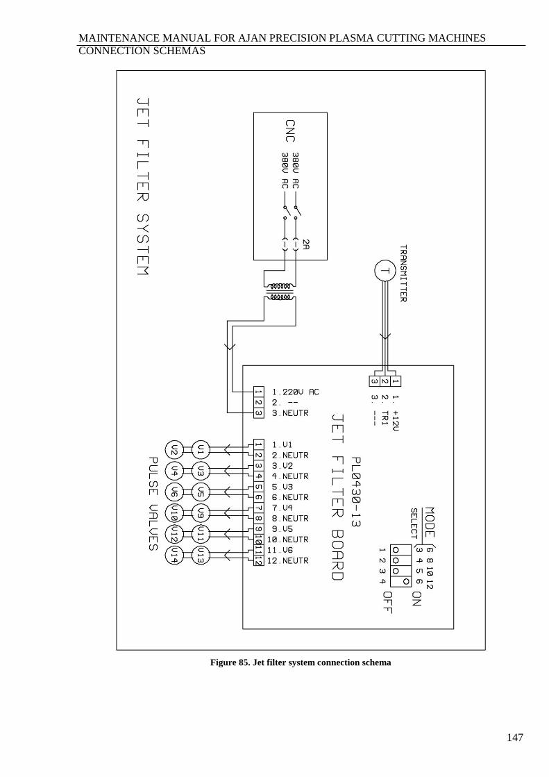
MAINTENANCE MANUAL FOR AJAN PRECISION PLASMA CUTTING MACHINES
CONNECTION SCHEMAS
147
Figure 85. Jet filter system connection schema
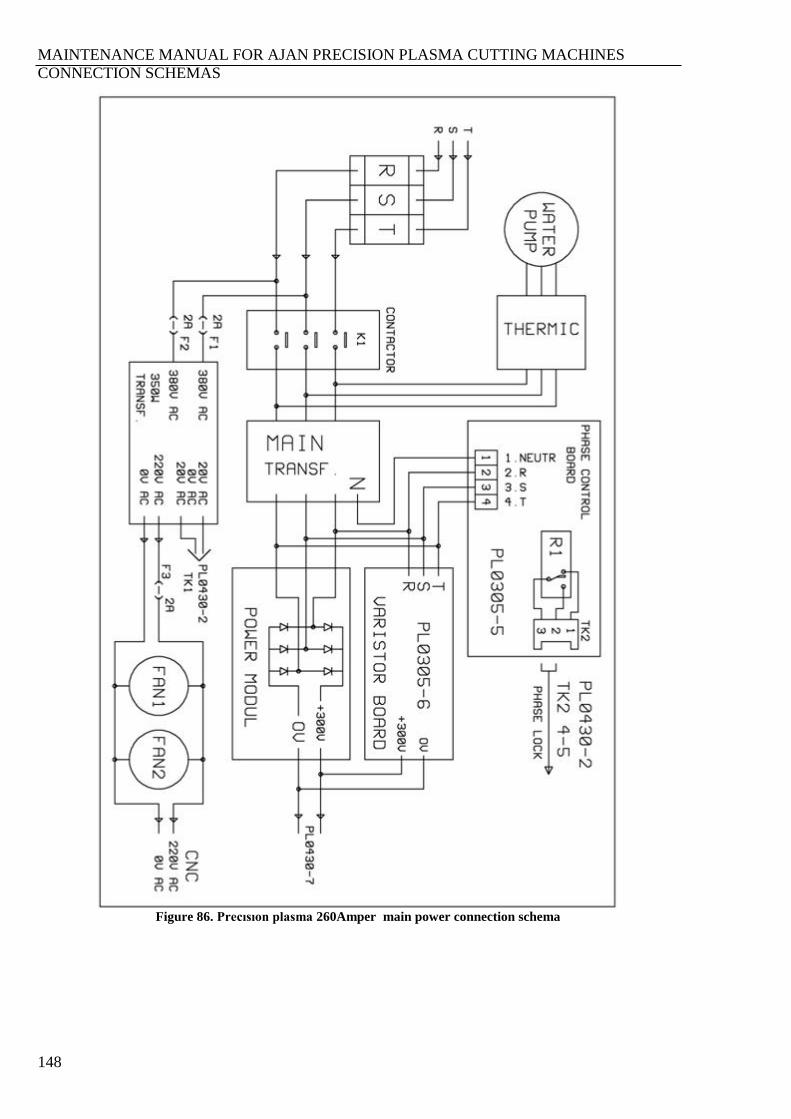
MAINTENANCE MANUAL FOR AJAN PRECISION PLASMA CUTTING MACHINES
CONNECTION SCHEMAS
148
Figure 86. Precısıon plasma 260Amper main power connection schema

MAINTENANCE MANUAL FOR AJAN PRECISION PLASMA CUTTING MACHINES
CONNECTION SCHEMAS
149
Figure 87. Precısıon plasma oxygen+marking control card connection schema
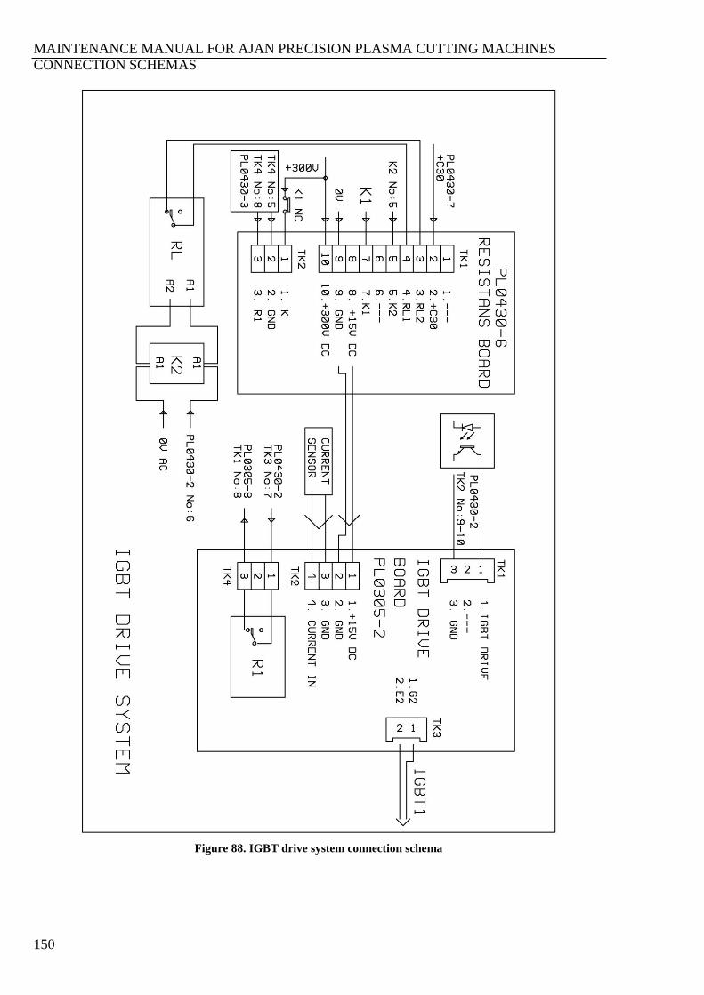
MAINTENANCE MANUAL FOR AJAN PRECISION PLASMA CUTTING MACHINES
CONNECTION SCHEMAS
150
Figure 88. IGBT drive system connection schema
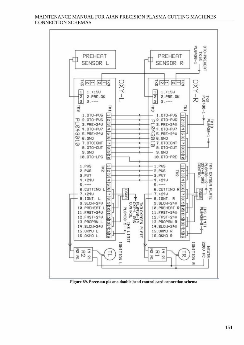
MAINTENANCE MANUAL FOR AJAN PRECISION PLASMA CUTTING MACHINES
CONNECTION SCHEMAS
151
Figure 89. Precısıon plasma double head control card connection schema
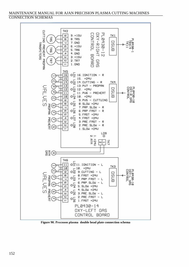
MAINTENANCE MANUAL FOR AJAN PRECISION PLASMA CUTTING MACHINES
CONNECTION SCHEMAS
152
Figure 90. Precısıon plasma double head plate connection schema
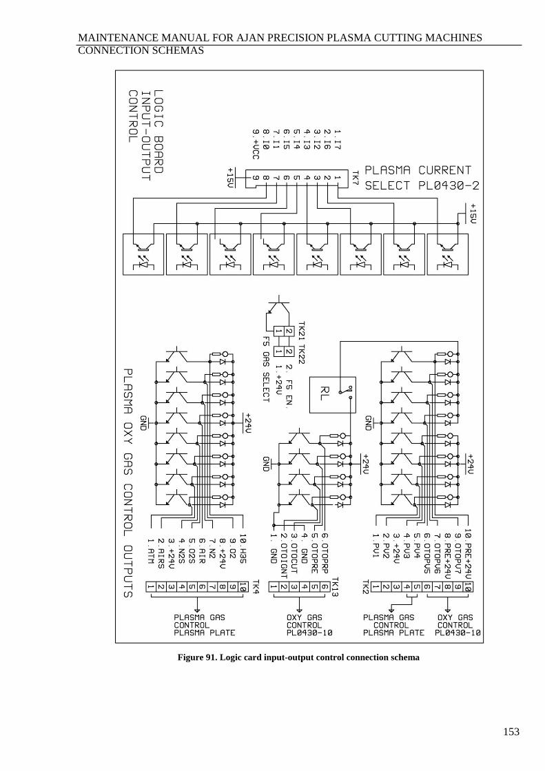
MAINTENANCE MANUAL FOR AJAN PRECISION PLASMA CUTTING MACHINES
CONNECTION SCHEMAS
153
Figure 91. Logic card input-output control connection schema
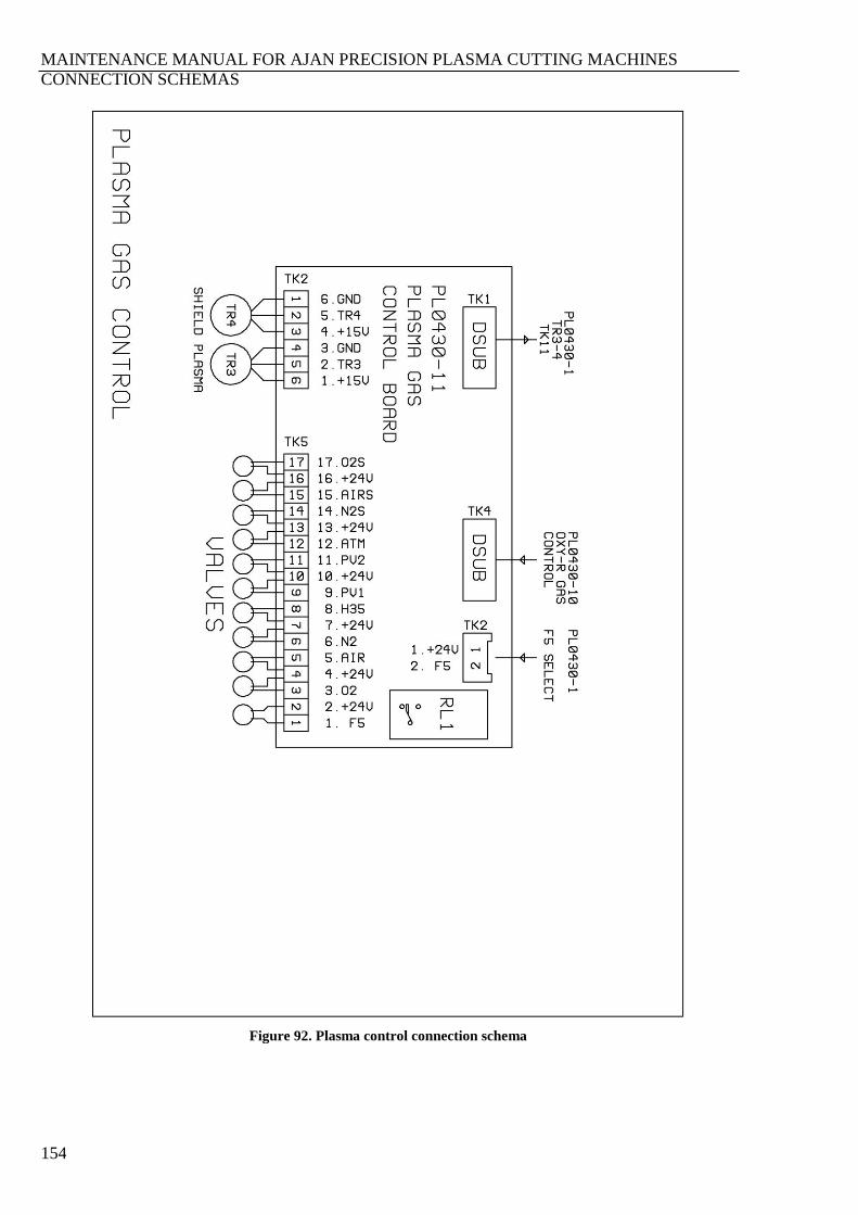
MAINTENANCE MANUAL FOR AJAN PRECISION PLASMA CUTTING MACHINES
CONNECTION SCHEMAS
154
Figure 92. Plasma control connection schema
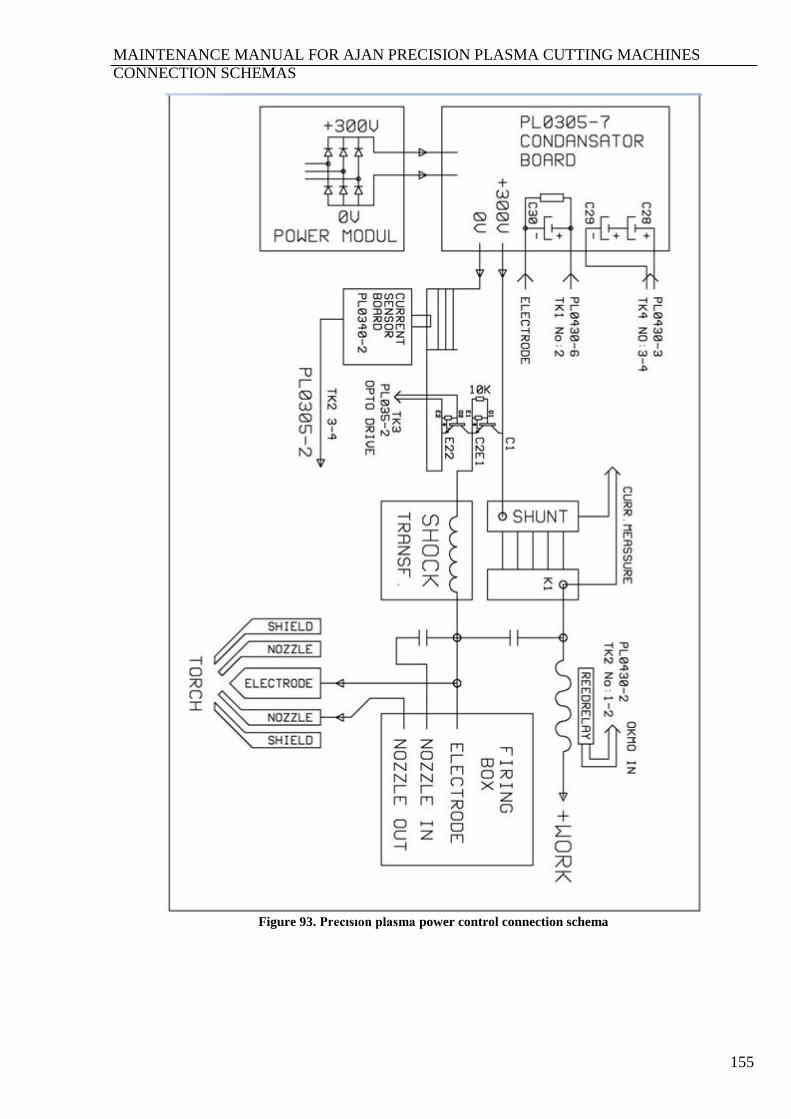
MAINTENANCE MANUAL FOR AJAN PRECISION PLASMA CUTTING MACHINES
CONNECTION SCHEMAS
155
Figure 93. Precısıon plasma power control connection schema
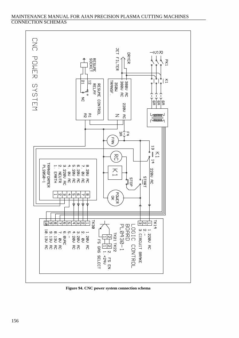
MAINTENANCE MANUAL FOR AJAN PRECISION PLASMA CUTTING MACHINES
CONNECTION SCHEMAS
156
Figure 94. CNC power system connection schema

MAINTENANCE MANUAL FOR AJAN PRECISION PLASMA CUTTING MACHINES
CONNECTION SCHEMAS
157
Figure 95. Remote control start-stop system connection schema
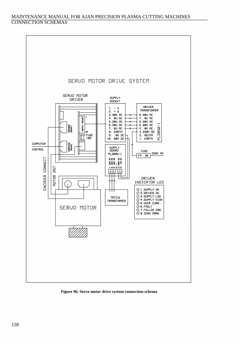
MAINTENANCE MANUAL FOR AJAN PRECISION PLASMA CUTTING MACHINES
CONNECTION SCHEMAS
158
Figure 96. Servo motor drive system connection schema
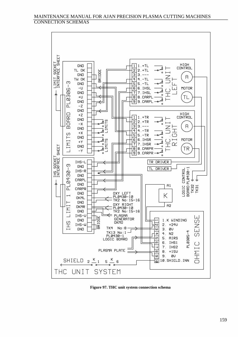
MAINTENANCE MANUAL FOR AJAN PRECISION PLASMA CUTTING MACHINES
CONNECTION SCHEMAS
159
Figure 97. THC unit system connection schema
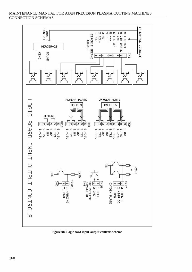
MAINTENANCE MANUAL FOR AJAN PRECISION PLASMA CUTTING MACHINES
CONNECTION SCHEMAS
160
Figure 98. Logic card input-output controls schema
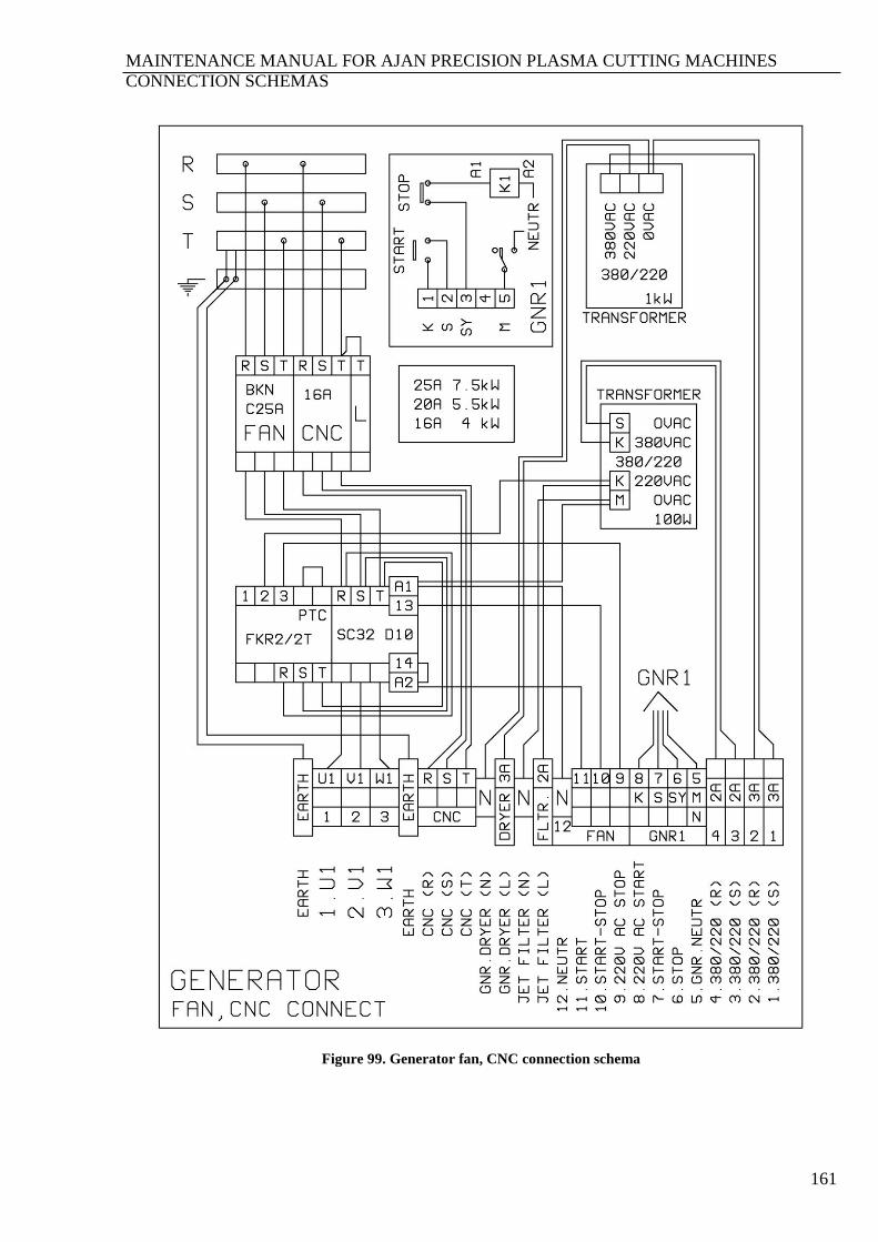
MAINTENANCE MANUAL FOR AJAN PRECISION PLASMA CUTTING MACHINES
CONNECTION SCHEMAS
161
Figure 99. Generator fan, CNC connection schema
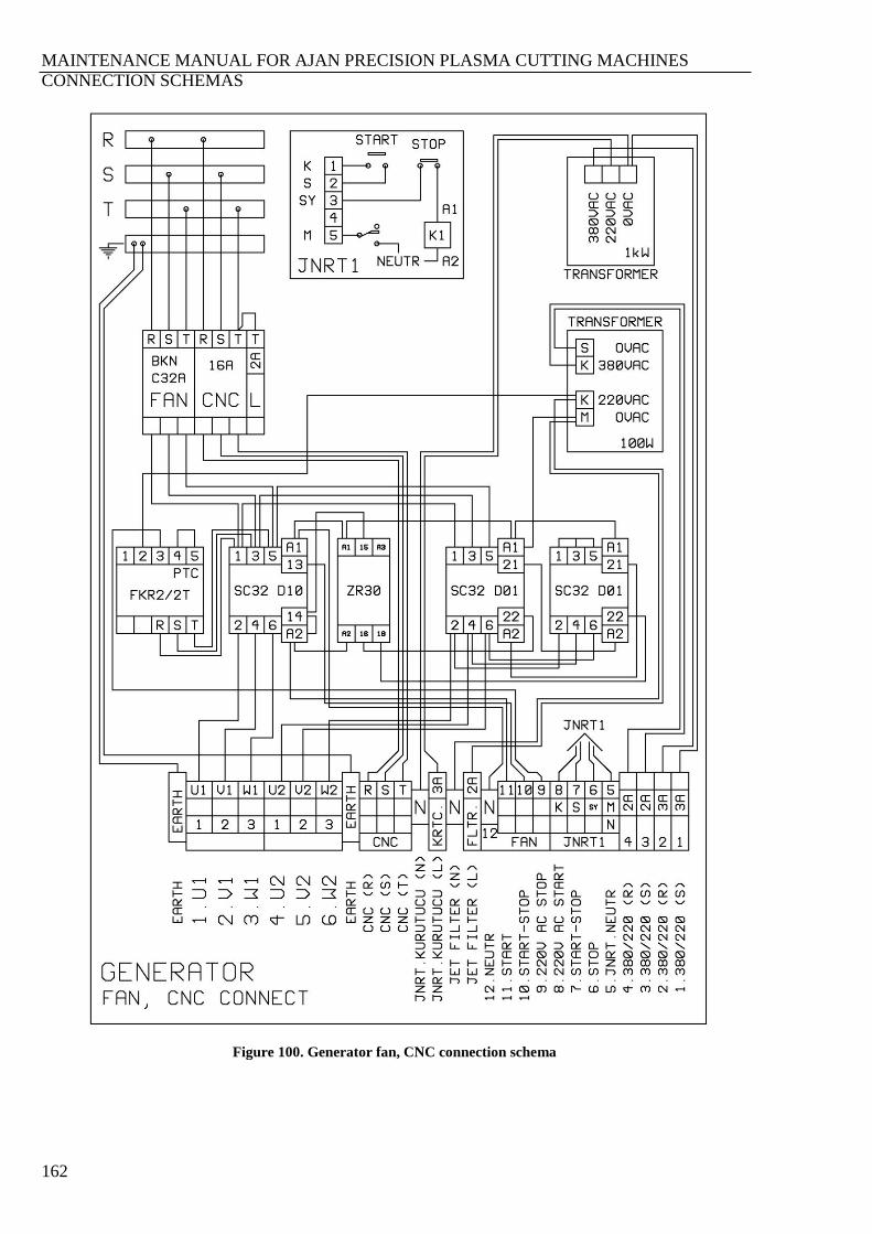
MAINTENANCE MANUAL FOR AJAN PRECISION PLASMA CUTTING MACHINES
CONNECTION SCHEMAS
162
Figure 100. Generator fan, CNC connection schema
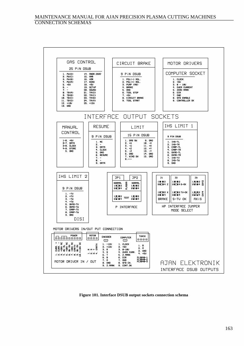
MAINTENANCE MANUAL FOR AJAN PRECISION PLASMA CUTTING MACHINES
CONNECTION SCHEMAS
163
Figure 101. Interface DSUB output sockets connection schema
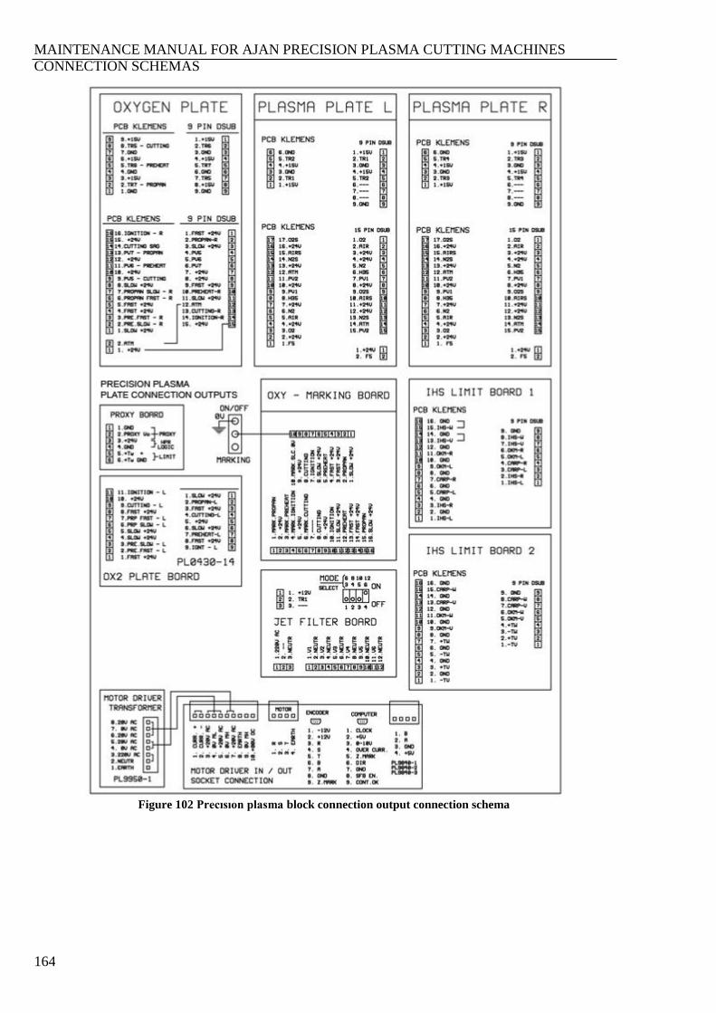
MAINTENANCE MANUAL FOR AJAN PRECISION PLASMA CUTTING MACHINES
CONNECTION SCHEMAS
164
Figure 102 Precısıon plasma block connection output connection schema
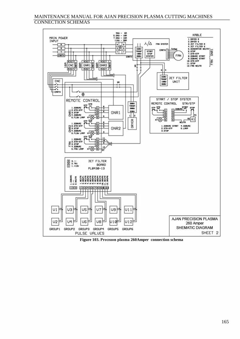
MAINTENANCE MANUAL FOR AJAN PRECISION PLASMA CUTTING MACHINES
CONNECTION SCHEMAS
165
Figure 103. Precısıon plasma 260Amper connection schema

MAINTENANCE MANUAL FOR AJAN PRECISION PLASMA CUTTING MACHINES
CONNECTION SCHEMAS
166
Figure 104. Precısıon plasma CNC plasma main transformer
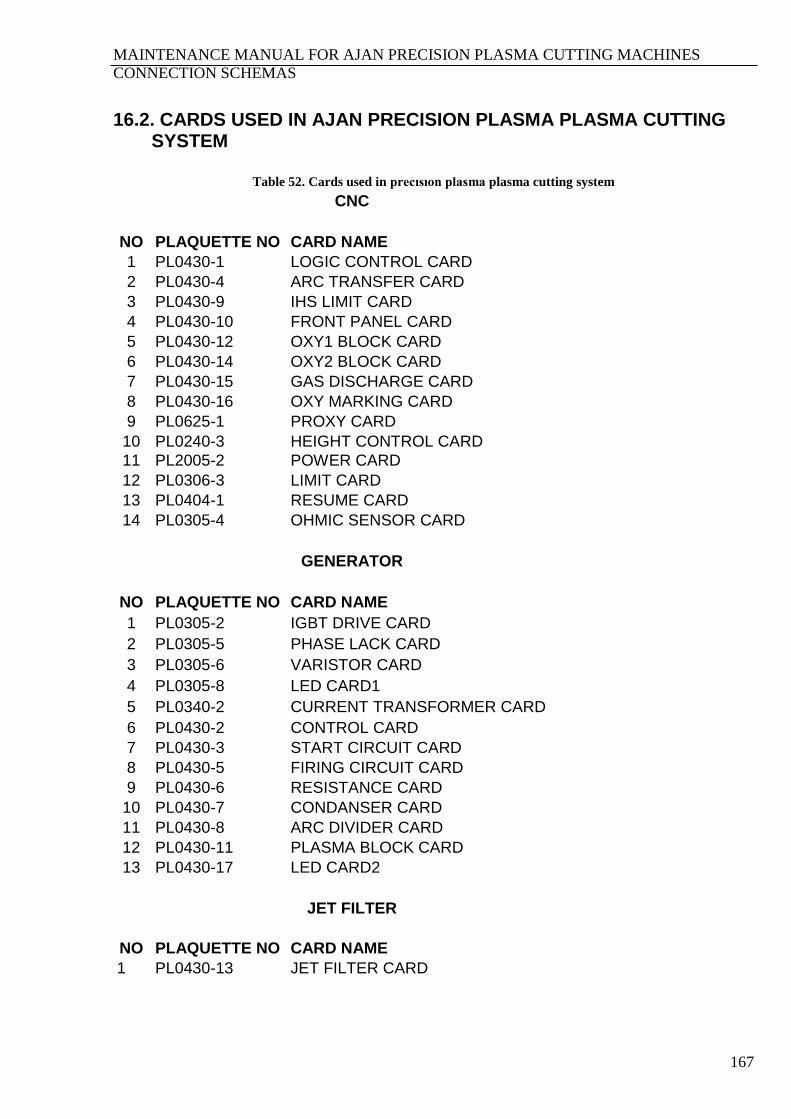
MAINTENANCE MANUAL FOR AJAN PRECISION PLASMA CUTTING MACHINES
CONNECTION SCHEMAS
167
16.2. CARDS USED IN AJAN PRECISION PLASMA PLASMA CUTTING SYSTEM
Table 52. Cards used in precısıon plasma plasma cutting system
CNC
NO PLAQUETTE NO CARD NAME
1 PL0430-1 LOGIC CONTROL CARD
2 PL0430-4 ARC TRANSFER CARD
3 PL0430-9 IHS LIMIT CARD
4 PL0430-10 FRONT PANEL CARD
5 PL0430-12 OXY1 BLOCK CARD
6 PL0430-14 OXY2 BLOCK CARD
7 PL0430-15 GAS DISCHARGE CARD
8 PL0430-16 OXY MARKING CARD
9 PL0625-1 PROXY CARD
10 PL0240-3 HEIGHT CONTROL CARD
11 PL2005-2 POWER CARD
12 PL0306-3 LIMIT CARD
13 PL0404-1 RESUME CARD
14 PL0305-4 OHMIC SENSOR CARD
GENERATOR
NO PLAQUETTE NO CARD NAME
1 PL0305-2 IGBT DRIVE CARD
2 PL0305-5 PHASE LACK CARD
3 PL0305-6 VARISTOR CARD
4 PL0305-8 LED CARD1
5 PL0340-2 CURRENT TRANSFORMER CARD
6 PL0430-2 CONTROL CARD
7 PL0430-3 START CIRCUIT CARD
8 PL0430-5 FIRING CIRCUIT CARD
9 PL0430-6 RESISTANCE CARD
10 PL0430-7 CONDANSER CARD
11 PL0430-8 ARC DIVIDER CARD
12 PL0430-11 PLASMA BLOCK CARD
13 PL0430-17 LED CARD2
JET FILTER
NO PLAQUETTE NO CARD NAME
1 PL0430-13 JET FILTER CARD
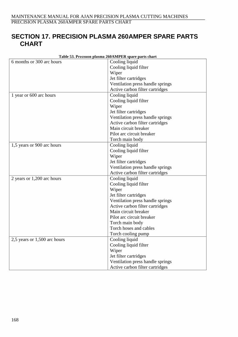
MAINTENANCE MANUAL FOR AJAN PRECISION PLASMA CUTTING MACHINES
PRECISION PLASMA 260AMPER SPARE PARTS CHART
168
SECTION 17. PRECISION PLASMA 260AMPER SPARE PARTS CHART
Table 53. Precısıon plasma 260AMPER spare parts chart
6 months or 300 arc hours Cooling liquid
Cooling liquid filter
Wiper
Jet filter cartridges
Ventilation press handle springs
Active carbon filter cartridges
1 year or 600 arc hours Cooling liquid
Cooling liquid filter
Wiper
Jet filter cartridges
Ventilation press handle springs
Active carbon filter cartridges
Main circuit breaker
Pilot arc circuit breaker
Torch main body
1,5 years or 900 arc hours Cooling liquid
Cooling liquid filter
Wiper
Jet filter cartridges
Ventilation press handle springs
Active carbon filter cartridges
2 years or 1,200 arc hours Cooling liquid
Cooling liquid filter
Wiper
Jet filter cartridges
Ventilation press handle springs
Active carbon filter cartridges
Main circuit breaker
Pilot arc circuit breaker
Torch main body
Torch hoses and cables
Torch cooling pump
2,5 years or 1,500 arc hours Cooling liquid
Cooling liquid filter
Wiper
Jet filter cartridges
Ventilation press handle springs
Active carbon filter cartridges
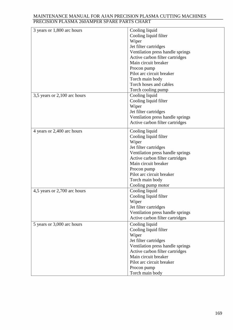
MAINTENANCE MANUAL FOR AJAN PRECISION PLASMA CUTTING MACHINES
PRECISION PLASMA 260AMPER SPARE PARTS CHART
169
3 years or 1,800 arc hours Cooling liquid
Cooling liquid filter
Wiper
Jet filter cartridges
Ventilation press handle springs
Active carbon filter cartridges
Main circuit breaker
Procon pump
Pilot arc circuit breaker
Torch main body
Torch hoses and cables
Torch cooling pump
3,5 years or 2,100 arc hours Cooling liquid
Cooling liquid filter
Wiper
Jet filter cartridges
Ventilation press handle springs
Active carbon filter cartridges
4 years or 2,400 arc hours Cooling liquid
Cooling liquid filter
Wiper
Jet filter cartridges
Ventilation press handle springs
Active carbon filter cartridges
Main circuit breaker
Procon pump
Pilot arc circuit breaker
Torch main body
Cooling pump motor
4,5 years or 2,700 arc hours Cooling liquid
Cooling liquid filter
Wiper
Jet filter cartridges
Ventilation press handle springs
Active carbon filter cartridges
5 years or 3,000 arc hours Cooling liquid
Cooling liquid filter
Wiper
Jet filter cartridges
Ventilation press handle springs
Active carbon filter cartridges
Main circuit breaker
Pilot arc circuit breaker
Procon pump
Torch main body
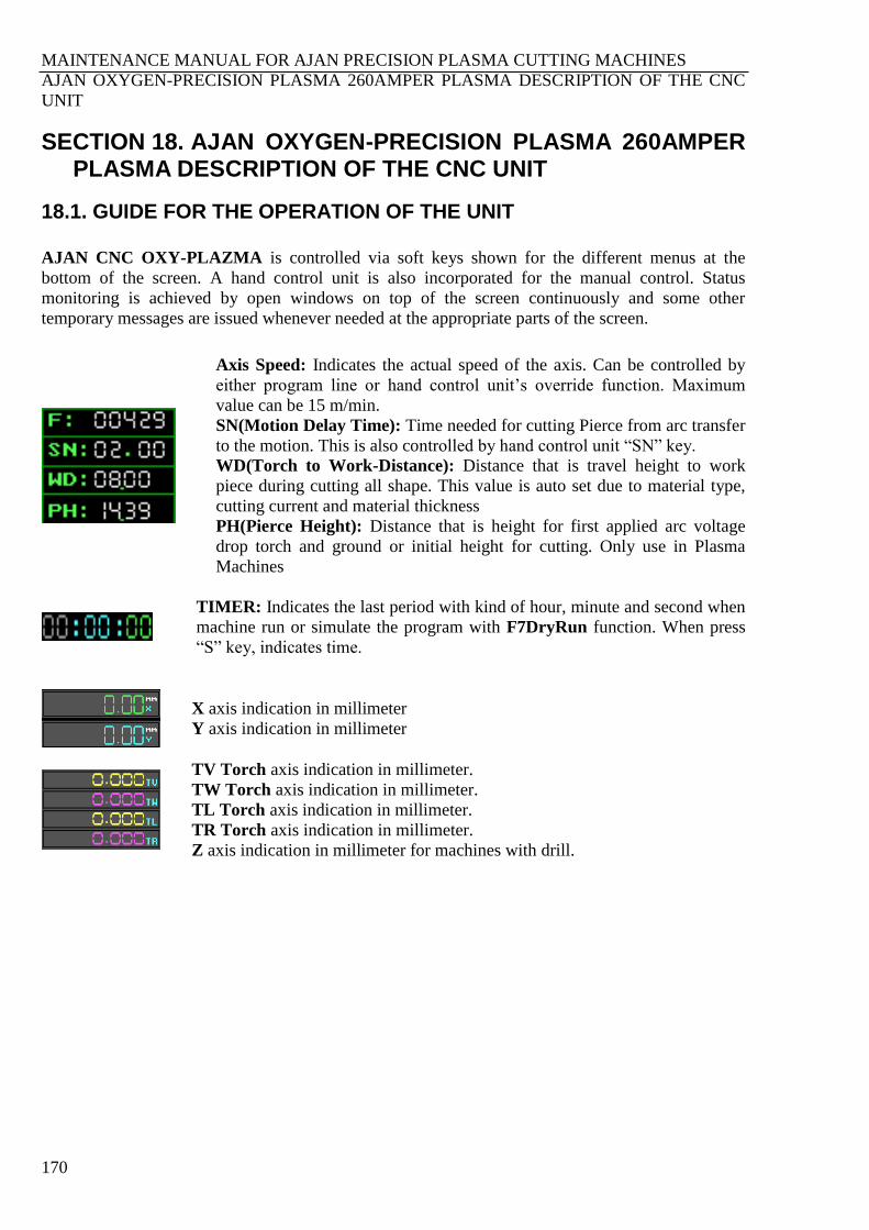
MAINTENANCE MANUAL FOR AJAN PRECISION PLASMA CUTTING MACHINES
AJAN OXYGEN-PRECISION PLASMA 260AMPER PLASMA DESCRIPTION OF THE CNC
UNIT
170
SECTION 18. AJAN OXYGEN-PRECISION PLASMA 260AMPER PLASMA DESCRIPTION OF THE CNC UNIT
18.1. GUIDE FOR THE OPERATION OF THE UNIT
AJAN CNC OXY-PLAZMA is controlled via soft keys shown for the different menus at the
bottom of the screen. A hand control unit is also incorporated for the manual control. Status
monitoring is achieved by open windows on top of the screen continuously and some other
temporary messages are issued whenever needed at the appropriate parts of the screen.
Axis Speed: Indicates the actual speed of the axis. Can be controlled by
either program line or hand control unit’s override function. Maximum
value can be 15 m/min.
SN(Motion Delay Time): Time needed for cutting Pierce from arc transfer
to the motion. This is also controlled by hand control unit “SN” key.
WD(Torch to Work-Distance): Distance that is travel height to work
piece during cutting all shape. This value is auto set due to material type,
cutting current and material thickness
PH(Pierce Height): Distance that is height for first applied arc voltage
drop torch and ground or initial height for cutting. Only use in Plasma
Machines
TIMER: Indicates the last period with kind of hour, minute and second when
machine run or simulate the program with F7DryRun function. When press
“S” key, indicates time.
X axis indication in millimeter
Y axis indication in millimeter
TV Torch axis indication in millimeter.
TW Torch axis indication in millimeter.
TL Torch axis indication in millimeter.
TR Torch axis indication in millimeter.
Z axis indication in millimeter for machines with drill.
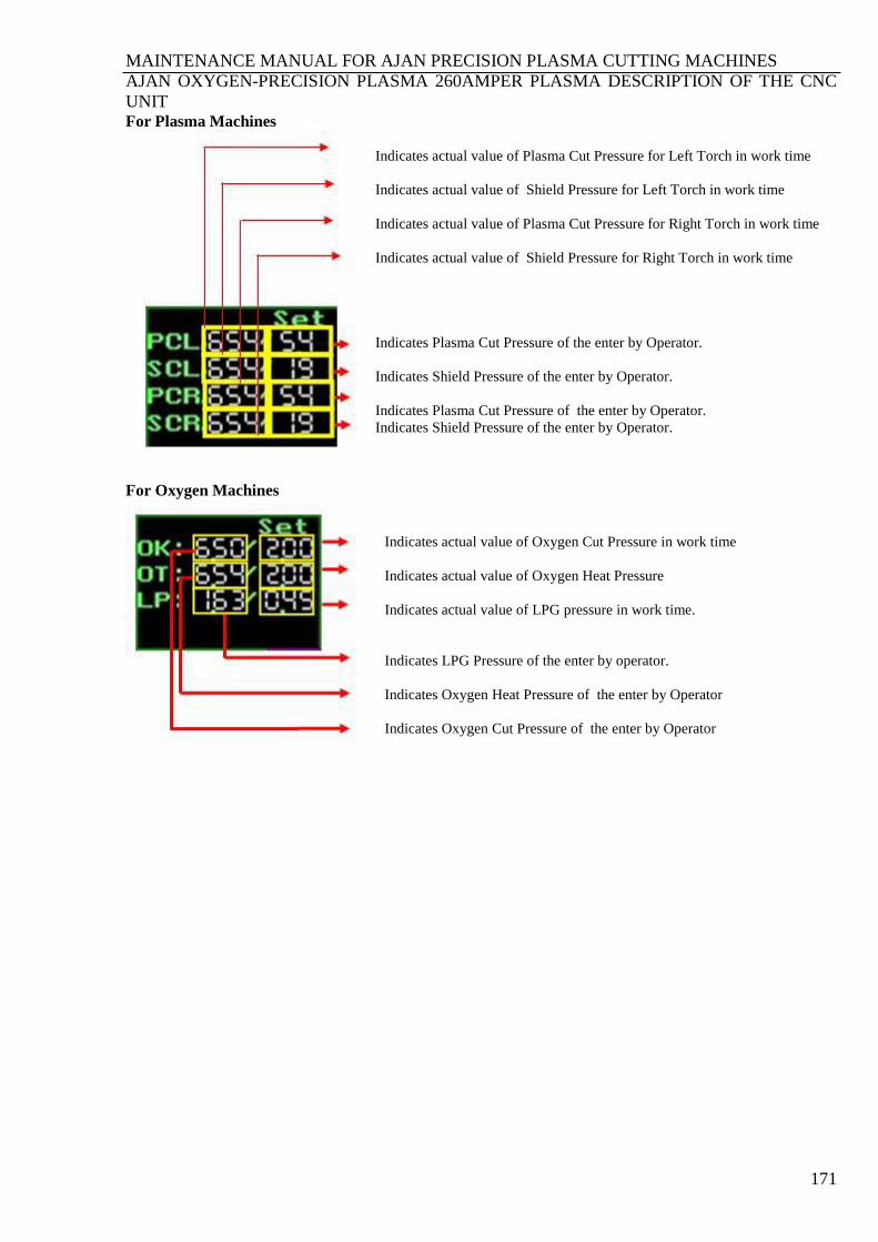
MAINTENANCE MANUAL FOR AJAN PRECISION PLASMA CUTTING MACHINES
AJAN OXYGEN-PRECISION PLASMA 260AMPER PLASMA DESCRIPTION OF THE CNC
UNIT
171
For Plasma Machines
Indicates actual value of Plasma Cut Pressure for Left Torch in work time
Indicates actual value of Shield Pressure for Left Torch in work time
Indicates actual value of Plasma Cut Pressure for Right Torch in work time
Indicates actual value of Shield Pressure for Right Torch in work time
Indicates Plasma Cut Pressure of the enter by Operator.
Indicates Shield Pressure of the enter by Operator.
Indicates Plasma Cut Pressure of the enter by Operator.
Indicates Shield Pressure of the enter by Operator.
For Oxygen Machines
Indicates actual value of Oxygen Cut Pressure in work time
Indicates actual value of Oxygen Heat Pressure
Indicates actual value of LPG pressure in work time.
Indicates LPG Pressure of the enter by operator.
Indicates Oxygen Heat Pressure of the enter by Operator
Indicates Oxygen Cut Pressure of the enter by Operator

MAINTENANCE MANUAL FOR AJAN PRECISION PLASMA CUTTING MACHINES
AJAN OXYGEN-PRECISION PLASMA 260AMPER PLASMA DESCRIPTION OF THE CNC
UNIT
172
PROGRAMMING: Programming is possible in main menu (Menu:0). The reserved part for
programming is the left zone of the screen and is activated by pressing ENTER key. Total 255 lines
can be programmed. 40 characters per line is possible. Further programming lines can be achieved
by calling the names of other subprograms. Programming editor works similar to popular editor
programs. In Menu:0 bar arrow keys, Page_Up and Page_Down keys are active.
Pressing ENTER key will bring the following window.
ENTER key will register the changes for that block and the next block will be highlighted “ESC”
key will cause editor to return to menu bar (Menu:0) and if some changes made in that particular
block, it will be left unchanged. F2 key will save the edited file. The reserved right zone of the
screen will be used for graphical display for machining and fault messages.
FILE NAME : Displays the name of the file.
START NO: Indicates the start line of the program to be executed.
END NO: Indicates the program finish line.
MENU: Pressing F10 function key will change menu bars under the screen. At the right bottom
corner the name of the menu will be displayed.
Menu 0 (main menu) bar:
Menu 1 bar:
Menu 2 bar:
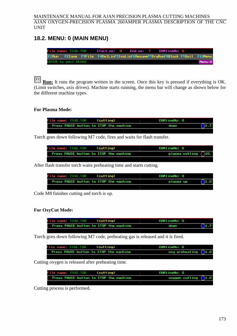
MAINTENANCE MANUAL FOR AJAN PRECISION PLASMA CUTTING MACHINES
AJAN OXYGEN-PRECISION PLASMA 260AMPER PLASMA DESCRIPTION OF THE CNC
UNIT
173
18.2. MENU: 0 (MAIN MENU)
Run: It runs the program written in the screen. Once this key is pressed if everything is OK.
(Limit switches, axis drives). Machine starts running, the menu bar will change as shown below for
the different machine types.
For Plasma Mode:
Torch goes down following M7 code, fires and waits for flash transfer.
After flash transfer torch waits preheating time and starts cutting.
Code M8 finishes cutting and torch is up.
For OxyCut Mode:
Torch goes down following M7 code, preheating gas is released and it is fired.
Cutting oxygen is released after preheating time.
Cutting process is performed.
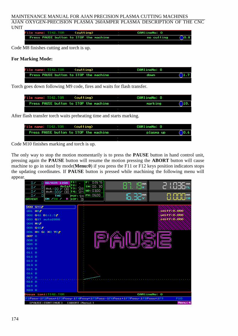
MAINTENANCE MANUAL FOR AJAN PRECISION PLASMA CUTTING MACHINES
AJAN OXYGEN-PRECISION PLASMA 260AMPER PLASMA DESCRIPTION OF THE CNC
UNIT
174
Code M8 finishes cutting and torch is up.
For Marking Mode:
Torch goes down following M9 code, fires and waits for flash transfer.
After flash transfer torch waits preheating time and starts marking.
Code M10 finishes marking and torch is up.
The only way to stop the motion momentarily is to press the PAUSE button in hand control unit,
pressing again the PAUSE button will resume the motion pressing the ABORT button will cause
machine to go in stand by mode(Menu:0) if you press the F11 or F12 keys position indicators stops
the updating coordinates. If PAUSE button is pressed while machining the following menu will
appear.
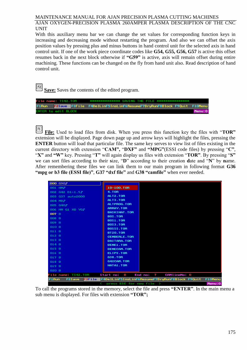
MAINTENANCE MANUAL FOR AJAN PRECISION PLASMA CUTTING MACHINES
AJAN OXYGEN-PRECISION PLASMA 260AMPER PLASMA DESCRIPTION OF THE CNC
UNIT
175
With this auxiliary menu bar we can change the set values for corresponding function keys in
increasing and decreasing mode without restarting the program. And also we can offset the axis
position values by pressing plus and minus buttons in hand control unit for the selected axis in hand
control unit. If one of the work piece coordinate codes like G54, G55, G56, G57 is active this offset
resumes back in the next block otherwise if “G59” is active, axis will remain offset during entire
machining. These functions can be changed on the fly from hand unit also. Read description of hand
control unit.
Save: Saves the contents of the edited program.
File: Used to load files from disk. When you press this function key the files with “TOR”
extension will be displayed. Page down page up and arrow keys will highlight the files, pressing the
ENTER button will load that particular file. The same key serves to view list of files existing in the
current directory with extension “CAM”, “DXF” and “MPG”(ESSI code files) by pressing “C”,
“X” and “W” key. Pressing “T” will again display us files with extension “TOR”. By pressing “S”
we can sort files according to their size, “D” according to their creation date and “N” by name.
After remembering these files we can link them to our main program in following format G36
“mpg or b3 file (ESSI file)”, G37 “dxf file” and G38 “camfile” when ever needed.
To call the programs stored in the memory, select the file and press “ENTER”. In the main menu a
sub menu is displayed. For files with extension “TOR”;

MAINTENANCE MANUAL FOR AJAN PRECISION PLASMA CUTTING MACHINES
AJAN OXYGEN-PRECISION PLASMA 260AMPER PLASMA DESCRIPTION OF THE CNC
UNIT
176
If we press “Y” the last opened file is saved and selected file opens, “ESC” will open the selected
file without saving the last opened file.
To create a new file; select “file button” by pressing function key F3, press ESC key and type in
8 character file name to the small window that highlights. This file must have a different name
from the list and then the block lines existing already in the editor will be saved as with this new
file name
After pressing the “ENTER” Key following line appears.
To save the old file press “Y” key. To leave the old file unsaved press ESC key.
Pushing Y key saves the old file before creating a new file. Following figure is displayed during
saving.
After this operation following menu bar appears.
If we want to open a new blank file with this name “B” letter has to be pushed
“ESC” button will cancel operation..
“Y” button will create the file with different name but same content as the last opened file.
DELETING FILES: Press F3 File function key. High light the file using arrow Keys, Page Up and
Page Down Keys then press “DELETE” key.
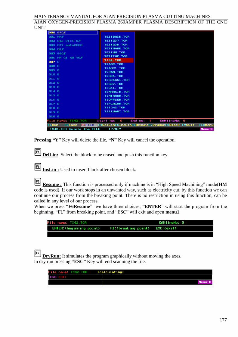
MAINTENANCE MANUAL FOR AJAN PRECISION PLASMA CUTTING MACHINES
AJAN OXYGEN-PRECISION PLASMA 260AMPER PLASMA DESCRIPTION OF THE CNC
UNIT
177
Pressing “Y” Key will delete the file, “N” Key will cancel the operation.
DelLin: Select the block to be erased and push this function key.
InsLin : Used to insert block after chosen block.
Resume : This function is processed only if machine is in “High Speed Machining” mode(HM
code is used). If our work stops in an unwanted way, such as electricity cut, by this function we can
continue our process from the breaking point. There is no restriction in using this function, can be
called in any level of our process.
When we press “F6Resume” we have three choices; “ENTER” will start the program from the
beginning, “F1” from breaking point, and “ESC” will exit and open menu1.
DryRun: It simulates the program graphically without moving the axes.
In dry run pressing “ESC” Key will end scanning the file.

MAINTENANCE MANUAL FOR AJAN PRECISION PLASMA CUTTING MACHINES
AJAN OXYGEN-PRECISION PLASMA 260AMPER PLASMA DESCRIPTION OF THE CNC
UNIT
178
Block: Sets the start and end block number of the program by pushing F8 function Key in
Menu:0. Enter start number for the program push ENTER, write the end number push ENTER if
the number is more than three digit it will automatically skip to next procedure. At the end if will
return back to the main menu.
Quit: Used to return back to DOS. If N key is pushed the operation will be cancelled.
Menu: Used to switch menu bars for Menu:0, Menu:1, Menu:2.
18.3. MENU:1
MDI: Used to move axes X, Y (for drill model Z axis can be used) to desired positions when
F1 is pressed. And Used for Entering F (feed rate), S (Spindle period for drill model), SM
(Maximum spindle period for drill model) and G5x (G54, G55, G56, G57) commands. In graphical
screen ENTER MDI will appear:

MAINTENANCE MANUAL FOR AJAN PRECISION PLASMA CUTTING MACHINES
AJAN OXYGEN-PRECISION PLASMA 260AMPER PLASMA DESCRIPTION OF THE CNC
UNIT
179
SAMPLE:
Enter MDI: x100 than “ENTER” will bring X axis to desired position of 100 mm. This operation
for each axis has to be repeated.
GoZERO: Will pull all axis (X,Y) (for drill model Z axis can be used) to “0” position
M Hand : Plasma is controlled by Hand Control Unit. Independently from the program all
axis can be controlled. Only “ABORT” button in hand control unit is available to exit and go to
the Menu:1.
****************************************** MENU6 *************************************************
*********************************************************************************************************
F4 ÷2: Used to divide axis values shown on the display by two while hand control unit is active.
Reset: Using this key is same as Menu1 F5 key.
Xangle: This key cancels machine’s XY plane and rotated XY plane to entering angle value.
Before using this key torch must be positioned one corner of the workpiece and reset all axes then
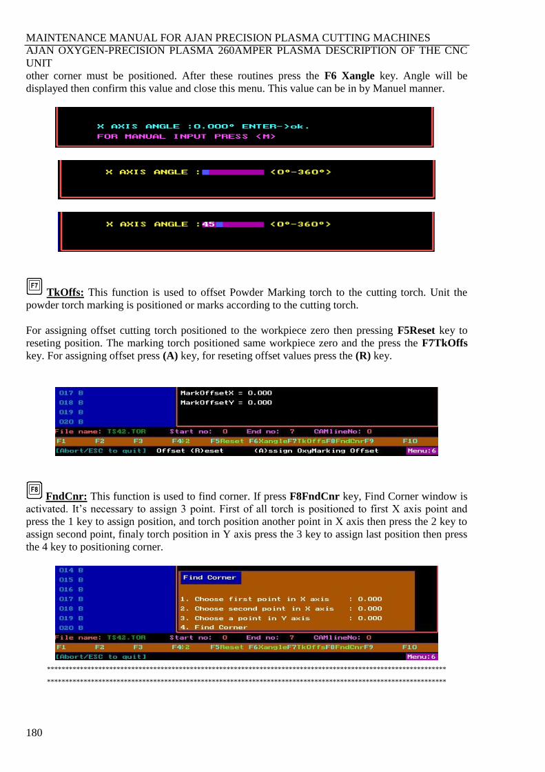
MAINTENANCE MANUAL FOR AJAN PRECISION PLASMA CUTTING MACHINES
AJAN OXYGEN-PRECISION PLASMA 260AMPER PLASMA DESCRIPTION OF THE CNC
UNIT
180
other corner must be positioned. After these routines press the F6 Xangle key. Angle will be
displayed then confirm this value and close this menu. This value can be in by Manuel manner.
TkOffs: This function is used to offset Powder Marking torch to the cutting torch. Unit the
powder torch marking is positioned or marks according to the cutting torch.
For assigning offset cutting torch positioned to the workpiece zero then pressing F5Reset key to
reseting position. The marking torch positioned same workpiece zero and the press the F7TkOffs
key. For assigning offset press (A) key, for reseting offset values press the (R) key.
FndCnr: This function is used to find corner. If press F8FndCnr key, Find Corner window is
activated. It’s necessary to assign 3 point. First of all torch is positioned to first X axis point and
press the 1 key to assign position, and torch position another point in X axis then press the 2 key to
assign second point, finaly torch position in Y axis press the 3 key to assign last position then press
the 4 key to positioning corner.
*************************************************************************************************************
*************************************************************************************************************
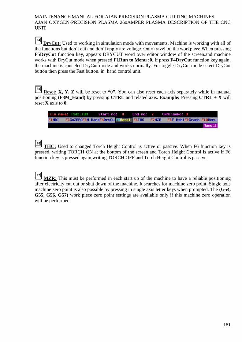
MAINTENANCE MANUAL FOR AJAN PRECISION PLASMA CUTTING MACHINES
AJAN OXYGEN-PRECISION PLASMA 260AMPER PLASMA DESCRIPTION OF THE CNC
UNIT
181
DryCut: Used to working in simulation mode with movements. Machine is working with all of
the functions but don’t cut and don’t apply arc voltage. Only travel on the workpiece.When pressing
F5DryCut function key, appears DRYCUT word over editor window of the screen.and machine
works with DryCut mode when pressed F1Run to Menu :0..If press F4DryCut function key again,
the machine is canceled DryCut mode and works normally. For toggle DryCut mode select DryCut
button then press the Fast button. in hand control unit.
Reset: X, Y, Z will be reset to “0”. You can also reset each axis separately while in manual
positioning (F3M_Hand) by pressing CTRL and related axis. Example: Pressing CTRL + X will
reset X axis to 0.
THC: Used to changed Torch Height Control is active or passive. When F6 function key is
pressed, writing TORCH ON at the bottom of the screen and Torch Height Control is active.If F6
function key is pressed again,writing TORCH OFF and Torch Height Control is passive.
MZR: This must be performed in each start up of the machine to have a reliable positioning
after electricity cut out or shut down of the machine. It searches for machine zero point. Single axis
machine zero point is also possible by pressing in single axis letter keys when prompted. The (G54,
G55, G56, G57) work piece zero point settings are available only if this machine zero operation
will be performed.

MAINTENANCE MANUAL FOR AJAN PRECISION PLASMA CUTTING MACHINES
AJAN OXYGEN-PRECISION PLASMA 260AMPER PLASMA DESCRIPTION OF THE CNC
UNIT
182
F_Hght: When F8 function Key is Pressed following menu bar will appear.
Graph: When F9 function key is pressed following menu bar will appear.
Use to control graphically screen, zoom and pan. Zoom scale and pan value will be displayed on the
graphically screen. In case when a “DXF” file is loaded graphically the figure will respond to these
changes. Down (), Up (), right (), left () Keys will shift the dotted line origin and page up
and page down will change the zoom scale.
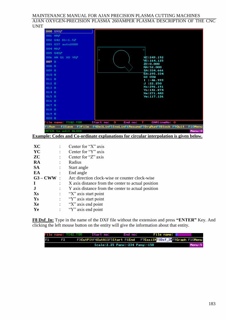
MAINTENANCE MANUAL FOR AJAN PRECISION PLASMA CUTTING MACHINES
AJAN OXYGEN-PRECISION PLASMA 260AMPER PLASMA DESCRIPTION OF THE CNC
UNIT
183
Example: Codes and Co-ordinate explanations for circular interpolation is given below.
XC : Center for “X” axis
YC : Center for “Y” axis
ZC : Center for “Z” axis
RA : Radius
SA : Start angle
EA : End angle
G3 – CWW : Arc direction clock-wise or counter clock-wise
I : X axis distance from the center to actual position
J : Y axis distance from the center to actual position
Xs : “X” axis start point
Ys : “Y” axis start point
Xe : “X” axis end point
Ye : “Y” axis end point
F8 Dxf_In: Type in the name of the DXF file without the extension and press “ENTER” Key. And
clicking the left mouse button on the entity will give the information about that entity.
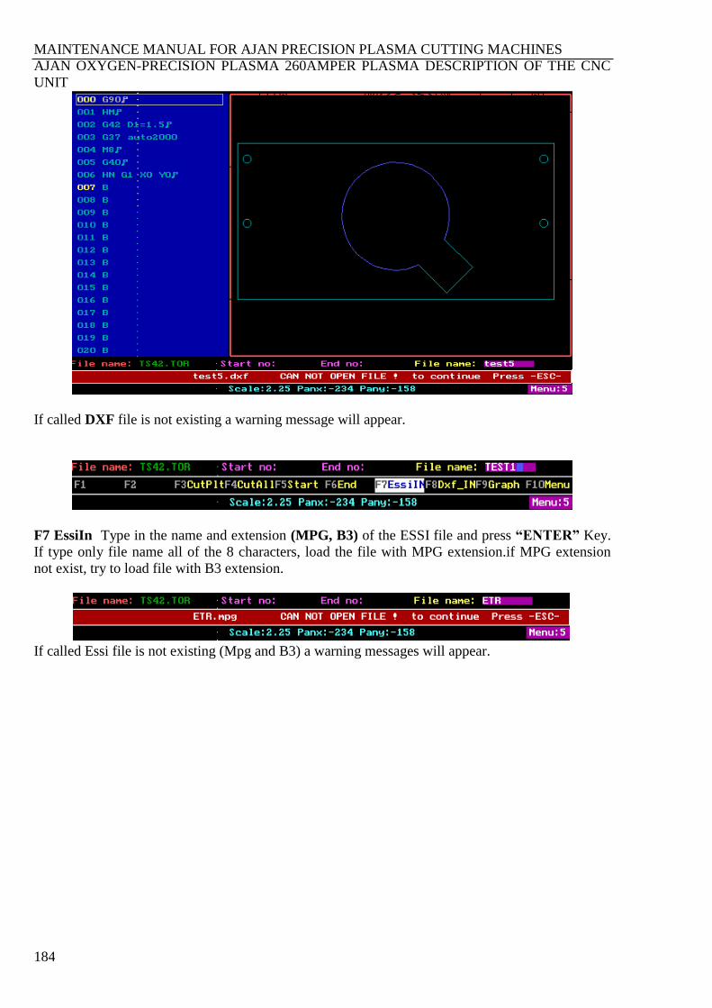
MAINTENANCE MANUAL FOR AJAN PRECISION PLASMA CUTTING MACHINES
AJAN OXYGEN-PRECISION PLASMA 260AMPER PLASMA DESCRIPTION OF THE CNC
UNIT
184
If called DXF file is not existing a warning message will appear.
F7 EssiIn Type in the name and extension (MPG, B3) of the ESSI file and press “ENTER” Key.
If type only file name all of the 8 characters, load the file with MPG extension.if MPG extension
not exist, try to load file with B3 extension.
If called Essi file is not existing (Mpg and B3) a warning messages will appear.
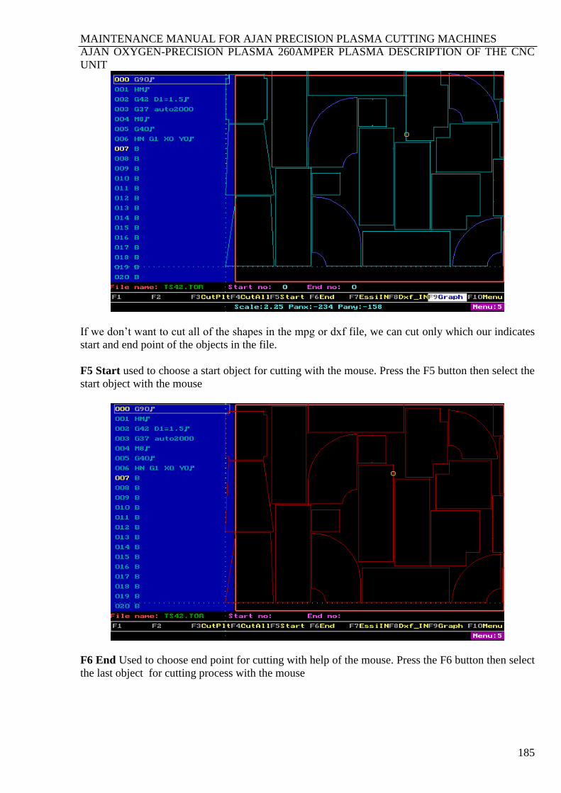
MAINTENANCE MANUAL FOR AJAN PRECISION PLASMA CUTTING MACHINES
AJAN OXYGEN-PRECISION PLASMA 260AMPER PLASMA DESCRIPTION OF THE CNC
UNIT
185
If we don’t want to cut all of the shapes in the mpg or dxf file, we can cut only which our indicates
start and end point of the objects in the file.
F5 Start used to choose a start object for cutting with the mouse. Press the F5 button then select the
start object with the mouse
F6 End Used to choose end point for cutting with help of the mouse. Press the F6 button then select
the last object for cutting process with the mouse
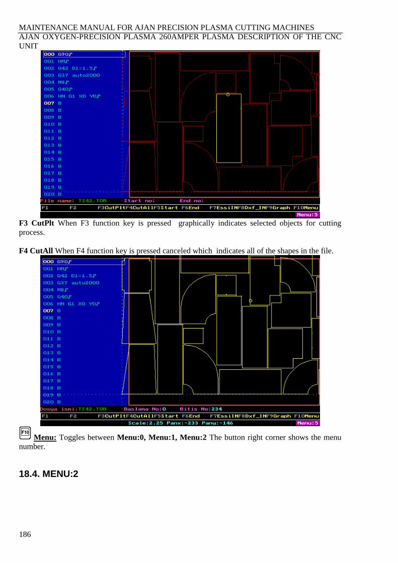
MAINTENANCE MANUAL FOR AJAN PRECISION PLASMA CUTTING MACHINES
AJAN OXYGEN-PRECISION PLASMA 260AMPER PLASMA DESCRIPTION OF THE CNC
UNIT
186
F3 CutPlt When F3 function key is pressed graphically indicates selected objects for cutting
process.
F4 CutAll When F4 function key is pressed canceled which indicates all of the shapes in the file.
Menu: Toggles between Menu:0, Menu:1, Menu:2 The button right corner shows the menu
number.
18.4. MENU:2
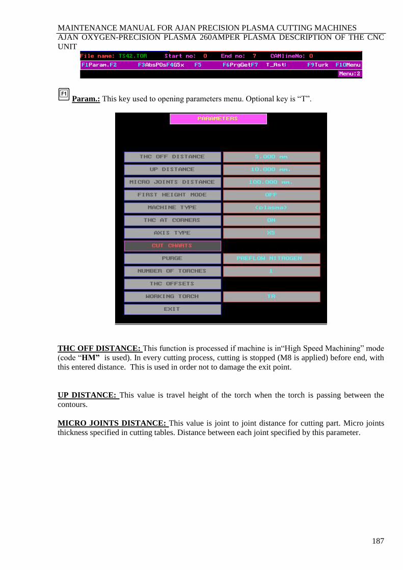
MAINTENANCE MANUAL FOR AJAN PRECISION PLASMA CUTTING MACHINES
AJAN OXYGEN-PRECISION PLASMA 260AMPER PLASMA DESCRIPTION OF THE CNC
UNIT
187
Param.: This key used to opening parameters menu. Optional key is “T”.
THC OFF DISTANCE: This function is processed if machine is in“High Speed Machining” mode
(code “HM” is used). In every cutting process, cutting is stopped (M8 is applied) before end, with
this entered distance. This is used in order not to damage the exit point.
UP DISTANCE: This value is travel height of the torch when the torch is passing between the
contours.
MICRO JOINTS DISTANCE: This value is joint to joint distance for cutting part. Micro joints
thickness specified in cutting tables. Distance between each joint specified by this parameter.
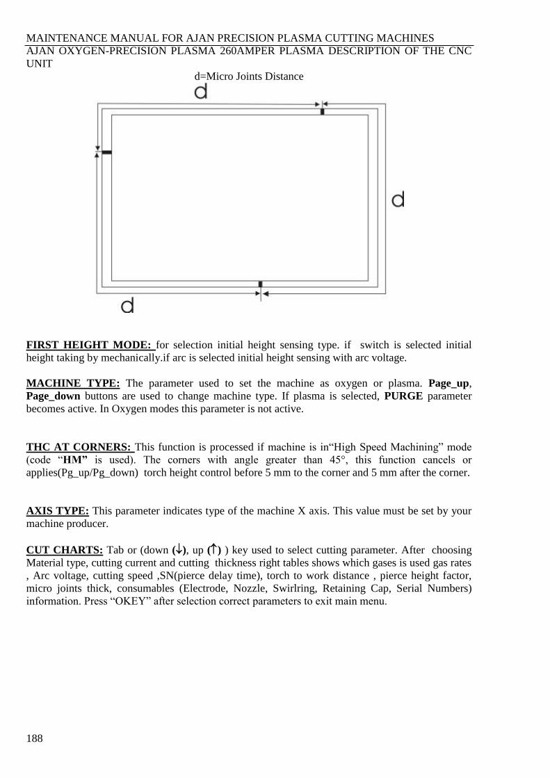
MAINTENANCE MANUAL FOR AJAN PRECISION PLASMA CUTTING MACHINES
AJAN OXYGEN-PRECISION PLASMA 260AMPER PLASMA DESCRIPTION OF THE CNC
UNIT
188
d=Micro Joints Distance
FIRST HEIGHT MODE: for selection initial height sensing type. if switch is selected initial
height taking by mechanically.if arc is selected initial height sensing with arc voltage.
MACHINE TYPE: The parameter used to set the machine as oxygen or plasma. Page_up,
Page_down buttons are used to change machine type. If plasma is selected, PURGE parameter
becomes active. In Oxygen modes this parameter is not active.
THC AT CORNERS: This function is processed if machine is in“High Speed Machining” mode
(code “HM” is used). The corners with angle greater than 45°, this function cancels or
applies(Pg_up/Pg_down) torch height control before 5 mm to the corner and 5 mm after the corner.
AXIS TYPE: This parameter indicates type of the machine X axis. This value must be set by your
machine producer.
CUT CHARTS: Tab or (down (), up () ) key used to select cutting parameter. After choosing
Material type, cutting current and cutting thickness right tables shows which gases is used gas rates
, Arc voltage, cutting speed ,SN(pierce delay time), torch to work distance , pierce height factor,
micro joints thick, consumables (Electrode, Nozzle, Swirlring, Retaining Cap, Serial Numbers)
information. Press “OKEY” after selection correct parameters to exit main menu.
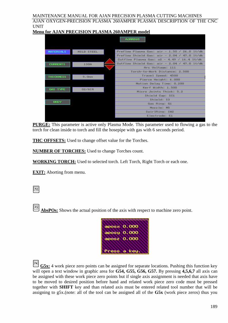
MAINTENANCE MANUAL FOR AJAN PRECISION PLASMA CUTTING MACHINES
AJAN OXYGEN-PRECISION PLASMA 260AMPER PLASMA DESCRIPTION OF THE CNC
UNIT
189
Menu for AJAN PRECISION PLASMA 260AMPER model
PURGE: This parameter is active only Plasma Mode. This parameter used to flowing a gas to the
torch for clean inside to torch and fill the hosepipe with gas with 6 seconds period.
THC OFFSETS: Used to change offset value for the Torches.
NUMBER OF TORCHES: Used to change Torches count.
WORKING TORCH: Used to selected torch. Left Torch, Right Torch or each one.
EXIT: Aborting from menu.
AbsPOs: Shows the actual position of the axis with respect to machine zero point.
G5x: 4 work piece zero points can be assigned for separate locations. Pushing this function key
will open a text window in graphic area for G54, G55, G56, G57. By pressing 4,5,6,7 all axis can
be assigned with these work piece zero points but if single axis assignment is needed that axis have
to be moved to desired position before hand and related work piece zero code must be pressed
together with SHIFT key and than related axis must be entered related tool number that will be
assigning to g5x.(note: all of the tool can be assigned all of the G5x (work piece zeros) thus you
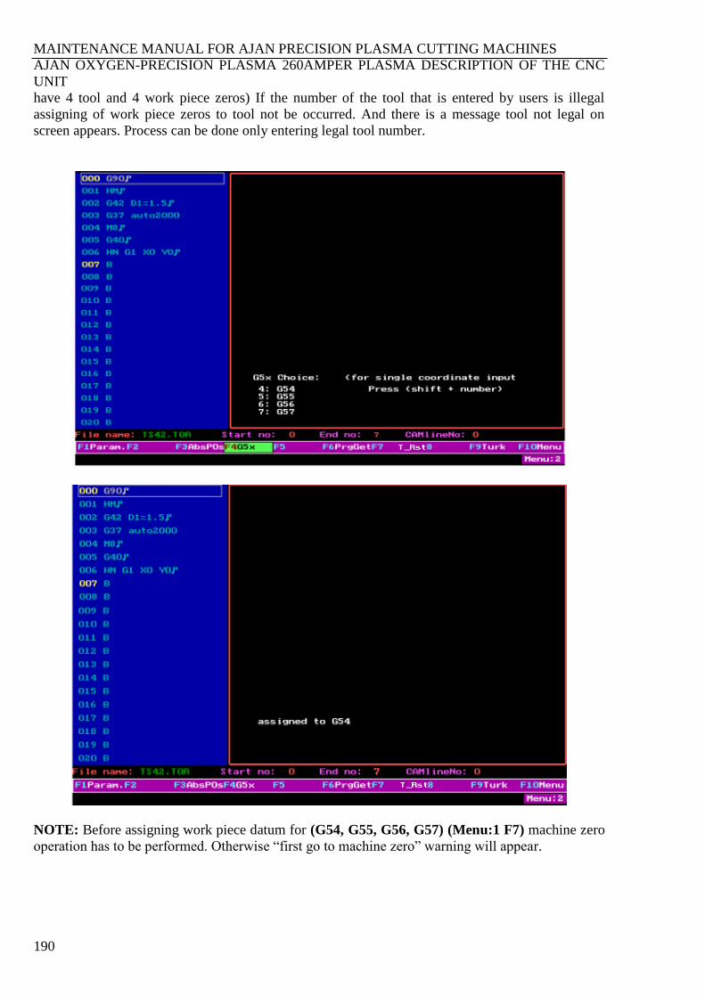
MAINTENANCE MANUAL FOR AJAN PRECISION PLASMA CUTTING MACHINES
AJAN OXYGEN-PRECISION PLASMA 260AMPER PLASMA DESCRIPTION OF THE CNC
UNIT
190
have 4 tool and 4 work piece zeros) If the number of the tool that is entered by users is illegal
assigning of work piece zeros to tool not be occurred. And there is a message tool not legal on
screen appears. Process can be done only entering legal tool number.
NOTE: Before assigning work piece datum for (G54, G55, G56, G57) (Menu:1 F7) machine zero
operation has to be performed. Otherwise “first go to machine zero” warning will appear.

MAINTENANCE MANUAL FOR AJAN PRECISION PLASMA CUTTING MACHINES
AJAN OXYGEN-PRECISION PLASMA 260AMPER PLASMA DESCRIPTION OF THE CNC
UNIT
191
GetPrg : When this function key is pressed the following menu appears.
“Y” To call a program with a new path name.
“ENTER” To accept already existing path written in memory.
“ESC” To cancel the operation.
NOTE 1: Path name up to 30 characters is possible
2: If you enter “P” shortcut key, you can reach last entered program.
T_Rst: Reset the Timer.
Turk: Changes program language to Turkish.
Menü: Toggles the menu.

MAINTENANCE MANUAL FOR AJAN PRECISION PLASMA CUTTING MACHINES
AJAN OXYGEN-PRECISION PLASMA 260AMPER PLASMA DESCRIPTION OF THE CNC
UNIT
192
18.5. OPERATION OF HAND CONTROL UNIT
Figure 105. Hand control unit label
FEED Percent override of the entered feed value by F during programming.
ARC VOLTAGE Percent override of the arc voltage value
PAUSE: Serves to stop the machines axis movements temporarily. Pressing this
button again will resume the motion.
ABORT: This button serves to stop the operation of machining and motion, when
PAUSE button is active. It also serves to exit from the manual positioning mode.
This button is enabled or disabled the Torch Height Control.
If press the or buttons when THC MODE button is enable, in
Oxygen Machines LPG pressure is increase or decrease. With button 0,005
bar, with button 0,01 bar, with button 0,1 bar increase or decrease.
This Button is used to change IHS MODE with button. Values
SW(Switch),ARC or OFF. If pressing and buttons when HIS
MODE button is enable, PH (Pierce Heigt) value is increase or decrease. With
button 0,05 mm, with button 0,1 mm, with button 1 mm increase
or decrease.
This button is used to selected the working torch with button.
If press and buttons when THC SEL button is enable, in Plasma
Machine, SCF (Shield Cut Pressure )with button 0,05 bar, with button
0,1 bar, with button 1 bar, in Oxygen Machines OT (Heat Pressure) with
button 0,01 bar, with button 0,1 bar, with button 1 bar increase or
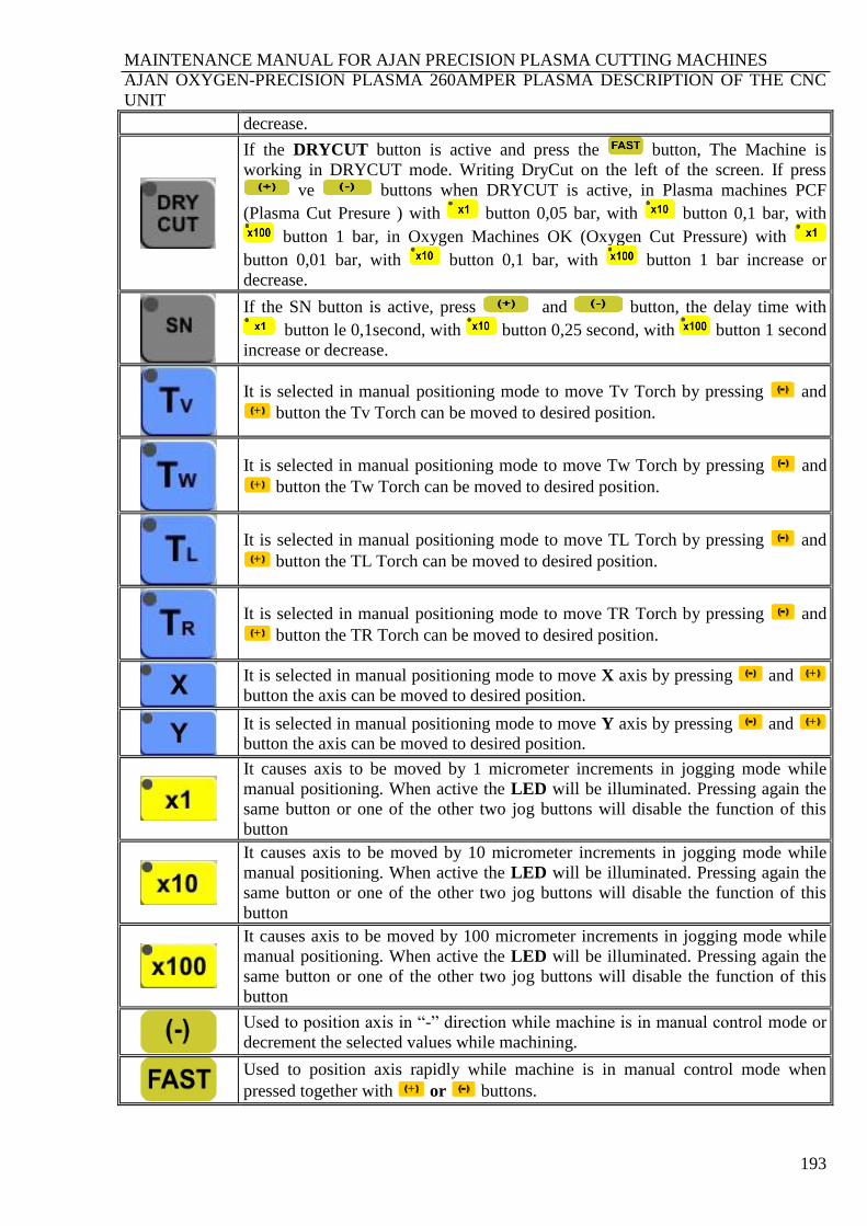
MAINTENANCE MANUAL FOR AJAN PRECISION PLASMA CUTTING MACHINES
AJAN OXYGEN-PRECISION PLASMA 260AMPER PLASMA DESCRIPTION OF THE CNC
UNIT
193
decrease.
If the DRYCUT button is active and press the button, The Machine is
working in DRYCUT mode. Writing DryCut on the left of the screen. If press
ve buttons when DRYCUT is active, in Plasma machines PCF
(Plasma Cut Presure ) with button 0,05 bar, with button 0,1 bar, with
button 1 bar, in Oxygen Machines OK (Oxygen Cut Pressure) with
button 0,01 bar, with button 0,1 bar, with button 1 bar increase or
decrease.
If the SN button is active, press and button, the delay time with
button le 0,1second, with button 0,25 second, with button 1 second
increase or decrease.
It is selected in manual positioning mode to move Tv Torch by pressing and + button the Tv Torch can be moved to desired position.
It is selected in manual positioning mode to move Tw Torch by pressing and + button the Tw Torch can be moved to desired position.
It is selected in manual positioning mode to move TL Torch by pressing and + button the TL Torch can be moved to desired position.
It is selected in manual positioning mode to move TR Torch by pressing and + button the TR Torch can be moved to desired position.
It is selected in manual positioning mode to move X axis by pressing and +
button the axis can be moved to desired position.
It is selected in manual positioning mode to move Y axis by pressing and +
button the axis can be moved to desired position.
It causes axis to be moved by 1 micrometer increments in jogging mode while
manual positioning. When active the LED will be illuminated. Pressing again the
same button or one of the other two jog buttons will disable the function of this
button
It causes axis to be moved by 10 micrometer increments in jogging mode while
manual positioning. When active the LED will be illuminated. Pressing again the
same button or one of the other two jog buttons will disable the function of this
button
It causes axis to be moved by 100 micrometer increments in jogging mode while
manual positioning. When active the LED will be illuminated. Pressing again the
same button or one of the other two jog buttons will disable the function of this
button
Used to position axis in “-” direction while machine is in manual control mode or
decrement the selected values while machining.
Used to position axis rapidly while machine is in manual control mode when
pressed together with + or buttons.
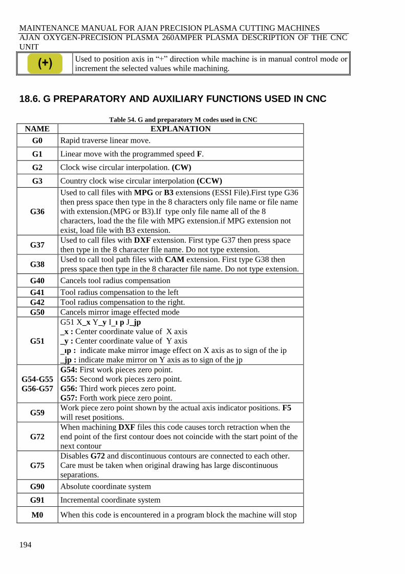
MAINTENANCE MANUAL FOR AJAN PRECISION PLASMA CUTTING MACHINES
AJAN OXYGEN-PRECISION PLASMA 260AMPER PLASMA DESCRIPTION OF THE CNC
UNIT
194
Used to position axis in “+” direction while machine is in manual control mode or
increment the selected values while machining.
18.6. G PREPARATORY AND AUXILIARY FUNCTIONS USED IN CNC
Table 54. G and preparatory M codes used in CNC
NAME EXPLANATION
G0 Rapid traverse linear move.
G1 Linear move with the programmed speed F.
G2 Clock wise circular interpolation. (CW)
G3 Country clock wise circular interpolation (CCW)
G36
Used to call files with MPG or B3 extensions (ESSI File).First type G36
then press space then type in the 8 characters only file name or file name
with extension.(MPG or B3).If type only file name all of the 8
characters, load the the file with MPG extension.if MPG extension not
exist, load file with B3 extension.
G37 Used to call files with DXF extension. First type G37 then press space
then type in the 8 character file name. Do not type extension.
G38 Used to call tool path files with CAM extension. First type G38 then
press space then type in the 8 character file name. Do not type extension.
G40 Cancels tool radius compensation
G41 Tool radius compensation to the left
G42 Tool radius compensation to the right.
G50 Cancels mirror image effected mode
G51
G51 X_x Y_y I_ı p J_jp
_x : Center coordinate value of X axis
_y : Center coordinate value of Y axis
_ıp : indicate make mirror image effect on X axis as to sign of the ip
_jp : indicate make mirror on Y axis as to sign of the jp
G54-G55
G56-G57
G54: First work pieces zero point.
G55: Second work pieces zero point.
G56: Third work pieces zero point.
G57: Forth work piece zero point.
G59 Work piece zero point shown by the actual axis indicator positions. F5
will reset positions.
G72
When machining DXF files this code causes torch retraction when the
end point of the first contour does not coincide with the start point of the
next contour
G75
Disables G72 and discontinuous contours are connected to each other.
Care must be taken when original drawing has large discontinuous
separations.
G90 Absolute coordinate system
G91 Incremental coordinate system
M0 When this code is encountered in a program block the machine will stop
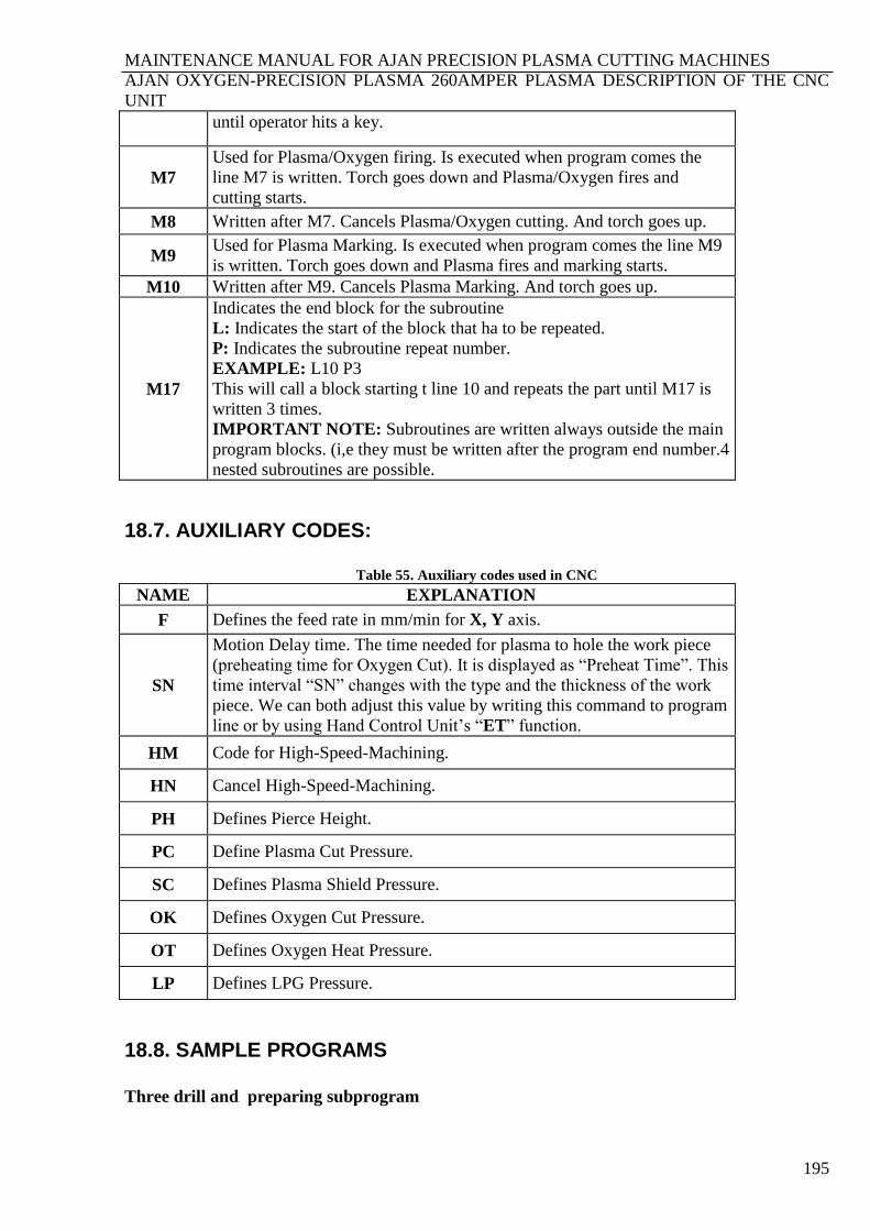
MAINTENANCE MANUAL FOR AJAN PRECISION PLASMA CUTTING MACHINES
AJAN OXYGEN-PRECISION PLASMA 260AMPER PLASMA DESCRIPTION OF THE CNC
UNIT
195
until operator hits a key.
M7
Used for Plasma/Oxygen firing. Is executed when program comes the
line M7 is written. Torch goes down and Plasma/Oxygen fires and
cutting starts.
M8 Written after M7. Cancels Plasma/Oxygen cutting. And torch goes up.
M9 Used for Plasma Marking. Is executed when program comes the line M9
is written. Torch goes down and Plasma fires and marking starts.
M10 Written after M9. Cancels Plasma Marking. And torch goes up.
M17
Indicates the end block for the subroutine
L: Indicates the start of the block that ha to be repeated.
P: Indicates the subroutine repeat number.
EXAMPLE: L10 P3
This will call a block starting t line 10 and repeats the part until M17 is
written 3 times.
IMPORTANT NOTE: Subroutines are written always outside the main
program blocks. (i,e they must be written after the program end number.4
nested subroutines are possible.
18.7. AUXILIARY CODES:
Table 55. Auxiliary codes used in CNC
NAME EXPLANATION
F Defines the feed rate in mm/min for X, Y axis.
SN
Motion Delay time. The time needed for plasma to hole the work piece
(preheating time for Oxygen Cut). It is displayed as “Preheat Time”. This
time interval “SN” changes with the type and the thickness of the work
piece. We can both adjust this value by writing this command to program
line or by using Hand Control Unit’s “ET” function.
HM Code for High-Speed-Machining.
HN Cancel High-Speed-Machining.
PH Defines Pierce Height.
PC Define Plasma Cut Pressure.
SC Defines Plasma Shield Pressure.
OK Defines Oxygen Cut Pressure.
OT Defines Oxygen Heat Pressure.
LP Defines LPG Pressure.
18.8. SAMPLE PROGRAMS
Three drill and preparing subprogram
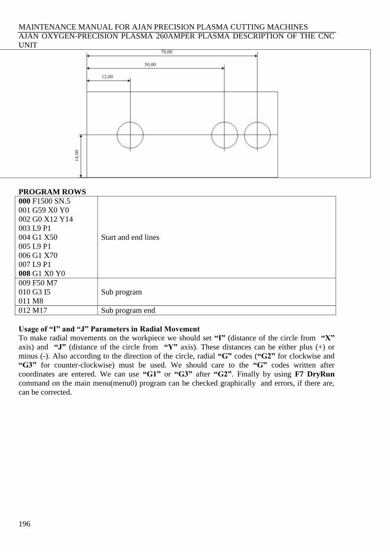
MAINTENANCE MANUAL FOR AJAN PRECISION PLASMA CUTTING MACHINES
AJAN OXYGEN-PRECISION PLASMA 260AMPER PLASMA DESCRIPTION OF THE CNC
UNIT
196
PROGRAM ROWS
000 F1500 SN.5
001 G59 X0 Y0
002 G0 X12 Y14
003 L9 P1
004 G1 X50
005 L9 P1
006 G1 X70
007 L9 P1
008 G1 X0 Y0
Start and end lines
009 F50 M7
010 G3 I5
011 M8
Sub program
012 M17 Sub program end
Usage of “I” and “J” Parameters in Radial Movement
To make radial movements on the workpiece we should set “I” (distance of the circle from “X”
axis) and “J” (distance of the circle from “Y” axis). These distances can be either plus (+) or
minus (-). Also according to the direction of the circle, radial “G” codes (“G2” for clockwise and
“G3” for counter-clockwise) must be used. We should care to the “G” codes written after
coordinates are entered. We can use “G1” or “G3” after “G2”. Finally by using F7 DryRun
command on the main menu(menu0) program can be checked graphically and errors, if there are,
can be corrected.

MAINTENANCE MANUAL FOR AJAN PRECISION PLASMA CUTTING MACHINES
AJAN OXYGEN-PRECISION PLASMA 260AMPER PLASMA DESCRIPTION OF THE CNC
UNIT
197
Example below shows followed linear and radial movements (clockwise and counter clockwise).
000 F200 G90 SN2
001 G59 X5 Y0
002 M7 F100 G1 X85
003 G3 J5 I0 X90 Y5
004 G1 Y25
005 G3 J0 I-5 X85 Y30
006 G1 X65
007 G2 J5 I0 X60 Y35
008 G1 Y55
009 G3 I-5 J0 X55 Y60
010 G1 X35
011 G3 J-5 I0 X30 Y55
012 G1 Y35
013 G2 I-5 J0 X25 Y30
014 G1 X5
015 G3 J-5 I0 X0 Y25
016 G1 Y5
017 G3 I5 J0 X5 Y0
018 M8
019 G1 X0 Y0
We can also write this program by using “Drawing Program” and “DXF” file extension. We draw
the sketch by using Drawing.exe program coming with the machine. The starting line and ending
line also must follow each other. This can be achieved by “pedit” command. We should think the
drawing as the work piece and pedit the sketch considering this. We should select lines following
each other while pediting. There mustn’t be any unselected line left after pedit operation. We should
also place the drawing to origin, 0,0,0. After completing this we can save and exit from drawing
program. In the main window edit the command lines and run the program. While working with
complex designs writing the program line by line can be very long and errors are more possible. By
using drawing program we can get rid of this problem. We don’t need any mathematical calculation
after drawing the sketch. We only call the drawing with file extension “DXF” and run the program.
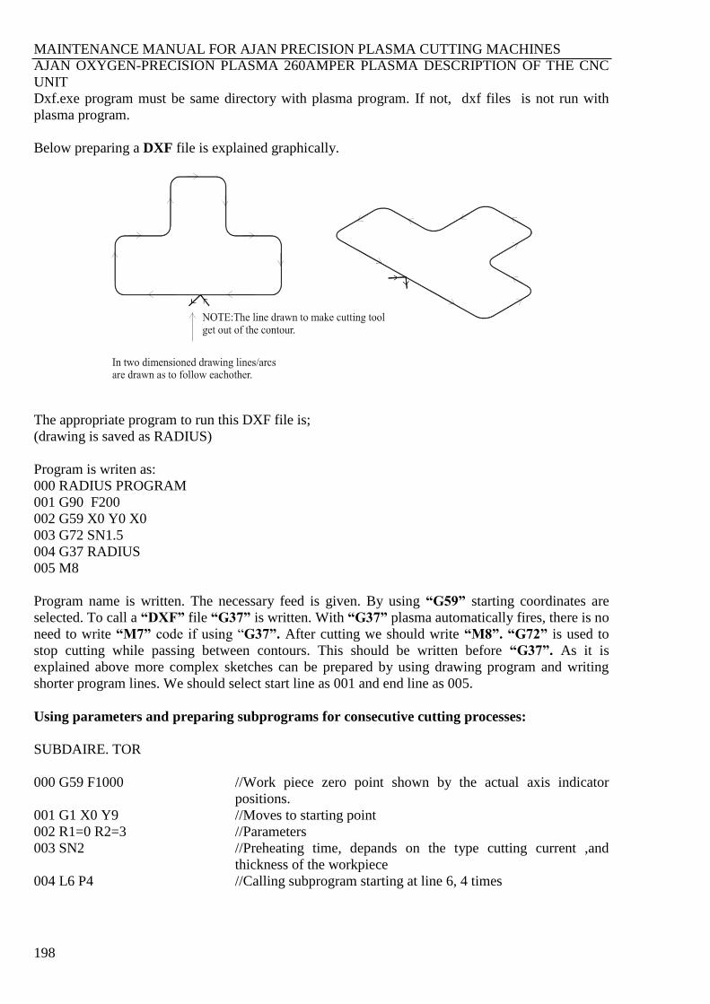
MAINTENANCE MANUAL FOR AJAN PRECISION PLASMA CUTTING MACHINES
AJAN OXYGEN-PRECISION PLASMA 260AMPER PLASMA DESCRIPTION OF THE CNC
UNIT
198
Dxf.exe program must be same directory with plasma program. If not, dxf files is not run with
plasma program.
Below preparing a DXF file is explained graphically.
The appropriate program to run this DXF file is;
(drawing is saved as RADIUS)
Program is writen as:
000 RADIUS PROGRAM
001 G90 F200
002 G59 X0 Y0 X0
003 G72 SN1.5
004 G37 RADIUS
005 M8
Program name is written. The necessary feed is given. By using “G59” starting coordinates are
selected. To call a “DXF” file “G37” is written. With “G37” plasma automatically fires, there is no
need to write “M7” code if using “G37”. After cutting we should write “M8”. “G72” is used to
stop cutting while passing between contours. This should be written before “G37”. As it is
explained above more complex sketches can be prepared by using drawing program and writing
shorter program lines. We should select start line as 001 and end line as 005.
Using parameters and preparing subprograms for consecutive cutting processes:
SUBDAIRE. TOR
000 G59 F1000
001 G1 X0 Y9
002 R1=0 R2=3
003 SN2
004 L6 P4
//Work piece zero point shown by the actual axis indicator
positions.
//Moves to starting point
//Parameters
//Preheating time, depands on the type cutting current ,and
thickness of the workpiece
//Calling subprogram starting at line 6, 4 times
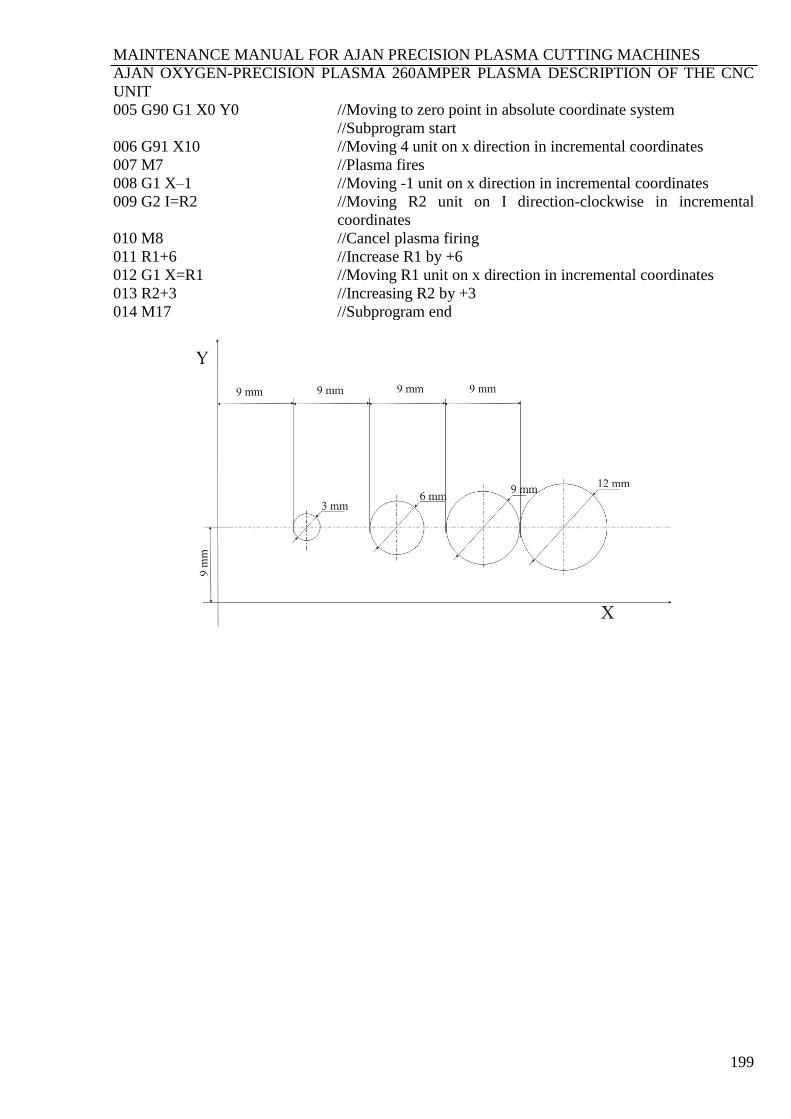
MAINTENANCE MANUAL FOR AJAN PRECISION PLASMA CUTTING MACHINES
AJAN OXYGEN-PRECISION PLASMA 260AMPER PLASMA DESCRIPTION OF THE CNC
UNIT
199
005 G90 G1 X0 Y0
006 G91 X10
007 M7
008 G1 X–1
009 G2 I=R2
010 M8
011 R1+6
012 G1 X=R1
013 R2+3
014 M17
//Moving to zero point in absolute coordinate system
//Subprogram start
//Moving 4 unit on x direction in incremental coordinates
//Plasma fires
//Moving -1 unit on x direction in incremental coordinates
//Moving R2 unit on I direction-clockwise in incremental
coordinates
//Cancel plasma firing
//Increase R1 by +6
//Moving R1 unit on x direction in incremental coordinates
//Increasing R2 by +3
//Subprogram end