Embed Size (px)
Citation preview
This document and the information contained herein are the property of
Appareo Systems, LLC and are confidential. They may not be disseminated
or redistributed without the written permission of Appareo Systems, LLC
APPAREO SYSTEMS, LLC FARGO, NORTH DAKOTA 58102
Stratus ES/ESG Maintenance Manual DOCUMENT NUMBER
600845-000024 Document Type
Certification Last Revised
3 October 2019 REV
3.0 Sheet
1 of 32
Maintenance Manual
Appareo Systems Stratus ES/ESG System SERIAL NUMBER:___________________ REGISTRATION NUMBER:____________
Stratus ES/ESG Maintenance Manual Rev: 3.0
Last Revised: October 3, 2019
Document Number: 600845-000024 Page 2 of 32
Record of Revision
Related Documentation
Document Number Title 600840-000031 Stratus ES/ESG Installation Instructions
600890-000049 Stratus ES/ESG Pilot’s Guide
601837-000024 Stratus ES/ESG Installation and Wiring Drawings
601837-000050 Stratus ES/ESG Helicopter Installation and Wiring Drawings
Warranty
To view the Stratus ES/ESG warranty, log into the Appareo Dealer Portal or visit www.appareo.com/resources.
Revision Number Change Description Effective
Date Inserted By
1.0 Initial Release 5/29/2015 Angela Lorenz
1.1 CM 10304 1/05/2016 Angela Lorenz
1.2 CM 10612 2/15/2016 Angela Lorenz
1.3 CM 11328 5/11/2016 Angela Lorenz
1.4 CM 11509 6/08/2016 Angela Lorenz
2.0 CM 13666 4/18/2017 Angela Lorenz
2.1 CM 13666 6/29/2017 Angela Lorenz
2.2 CM 14495 2/20/2018 Angela Lorenz
3.0 Added maintenance for helicopter installations 10/03/2019 Angela Lorenz
Stratus ES/ESG Maintenance Manual Rev: 3.0
Last Revised: October 3, 2019
Document Number: 600845-000024 Page 3 of 32
Table of Contents
Abbreviations and Definitions ......................................................................................................... 6
1. INTRODUCTION ................................................................................................................ 7
1.1. PURPOSE .................................................................................................................... 7
1.2. CERTIFICATION INFORMATION ............................................................................... 7
1.3. SYSTEM DESCRIPTION ............................................................................................. 9
1.4. TOOLS ........................................................................................................................ 11
1.5. WEIGHT AND BALANCE INFORMATION ................................................................ 11
1.6. EQUIPMENT DIMENSIONS ...................................................................................... 12
1.7. ELECTRICAL SPECIFICATIONS .............................................................................. 12
1.8. POWER REQUIREMENTS ........................................................................................ 12
2. AIRWORTHINESS LIMITATIONS.................................................................................... 13
3. INSPECTION REQUIREMENTS AND OVERHAUL (ATA CHAPTER 5) ....................... 13
3.1. GENERAL INSPECTION INFORMATION ................................................................. 13
4. DIMENSIONS AND ACCESS (ATA CHAPTER 6) .......................................................... 14
4.1. COMPONENT LOCATIONS ...................................................................................... 14
4.2. MAINTENANCE INSTRUCTIONS ............................................................................. 14
4.3. FUNCTIONAL TESTS ................................................................................................ 18
5. LIFTING AND SHORING (ATA CHAPTER 7) ................................................................. 21
5.1. LIFTING INFORMATION ........................................................................................... 21
5.2. SHORING INFORMATION ........................................................................................ 21
6. LEVELING AND WEIGHING (ATA CHAPTER 8) ............................................................ 21
6.1. LEVELING INFORMATION ........................................................................................ 21
6.2. WEIGHING INFORMATION ....................................................................................... 21
7. TOWING AND TAXIING (ATA CHAPTER 9) ................................................................... 22
7.1. TOW INSTRUCTIONS ............................................................................................... 22
7.2. TAXIING INSTRUCTIONS ......................................................................................... 22
8. PARKING, MOORING AND STORAGE (ATA CHAPTER 10) ........................................ 22
8.1. MOORING INFORMATION ........................................................................................ 22
8.2. PARKING INFORMATION ......................................................................................... 22
8.3. STORAGE LIMITATIONS .......................................................................................... 22
9. PLACARDS AND MARKINGS (ATA CHAPTER 11) ....................................................... 22
10. SERVICING (ATA CHAPTER 12) .................................................................................... 23
10.1. SERVICING INFORMATION ..................................................................................... 23
Stratus ES/ESG Maintenance Manual Rev: 3.0
Last Revised: October 3, 2019
Document Number: 600845-000024 Page 4 of 32
10.2. LUBRICATION INFORMATION ................................................................................. 26
10.3. EQUIPMENT REQUIRED FOR SERVICING ............................................................ 26
10.4. CONSUMABLE MATERIALS ..................................................................................... 26
11. WIRING DIAGRAMS ........................................................................................................ 27
Stratus ES/ESG Maintenance Manual Rev: 3.0
Last Revised: October 3, 2019
Document Number: 600845-000024 Page 5 of 32
List of Figures
Figure 1: Stratus ES/ESG airplane installation diagram .............................................................. 14 Figure 2: Stratus ES/ESG helicopter installation diagram ........................................................... 15 Figure 3: Locking mechanism location ......................................................................................... 15 Figure 4: Software update wiring diagram ................................................................................... 17 Figure 5: Interface for Stratus ES/ESG functional tests ............................................................... 19 Figure 6: Pin-out ........................................................................................................................... 28 Figure 7: Stratus ES wiring diagram with parallel altitude encoder ............................................. 29 Figure 8: Stratus ES wiring diagram with serial altitude encoder ................................................ 30 Figure 9: Stratus ESG wiring diagram with parallel altitude encoder .......................................... 31 Figure 10: Stratus ESG wiring diagram with serial altitude encoder ........................................... 32
List of Tables
Table 1: TSO compliance ............................................................................................................... 7 Table 2: TSO deviations ................................................................................................................. 8 Table 3: Criticality level ................................................................................................................... 8 Table 4: Embedded hardware and software .................................................................................. 9 Table 5: Required hardware (airplane installation) (LRUs) ............................................................ 9 Table 6: Required hardware (airplane installation) (COTS components) .................................... 10 Table 7: Required hardware (helicopter installation) (LRUs) ....................................................... 10 Table 8: Required hardware (helicopter installation) (COTS components) ................................. 11 Table 9: Required tools ................................................................................................................. 11 Table 10: Stratus ES/ESG weight ................................................................................................ 11 Table 11: Equipment dimensions ................................................................................................. 12 Table 12: Electrical specifications ................................................................................................ 12 Table 13: Power requirements ..................................................................................................... 12 Table 14: Scheduled maintenance ............................................................................................... 13 Table 15: Troubleshooting guide .................................................................................................. 26
Stratus ES/ESG Maintenance Manual Rev: 3.0
Last Revised: October 3, 2019
Document Number: 600845-000024 Page 6 of 32
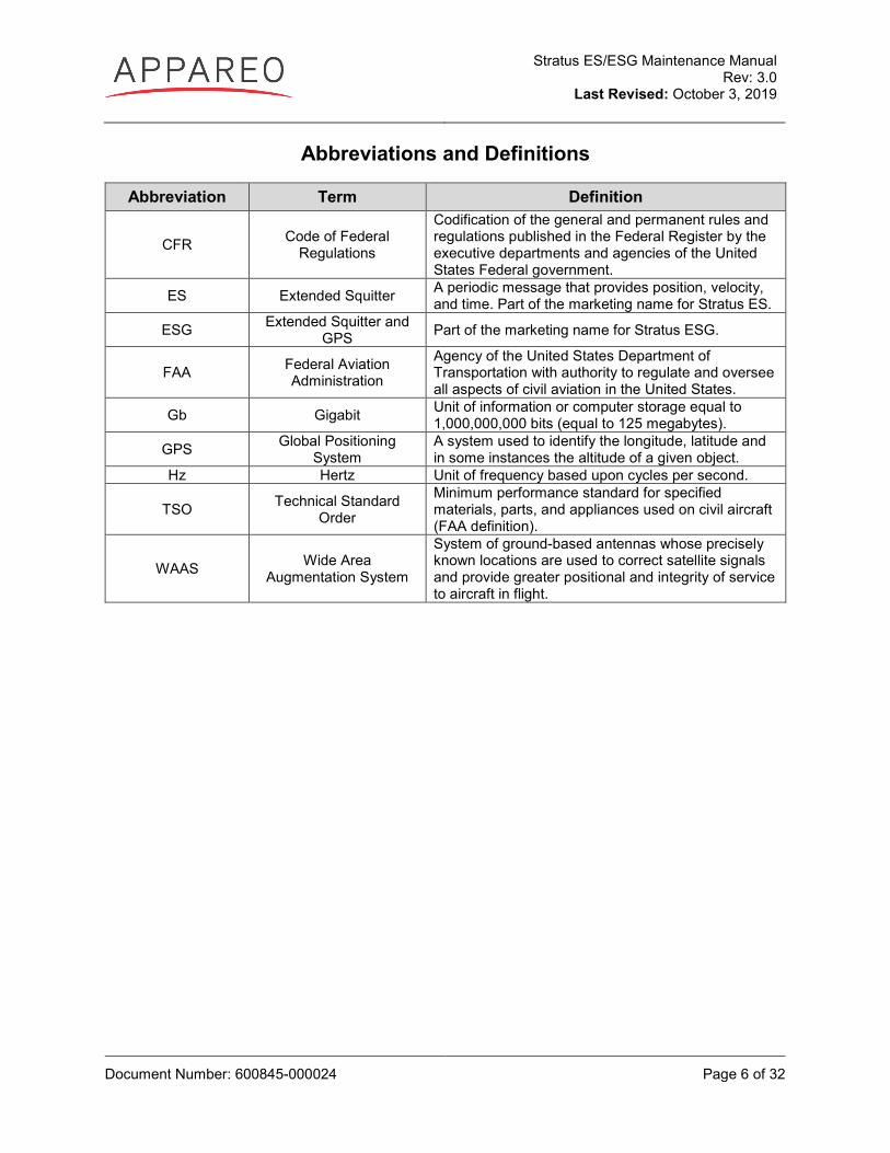
Abbreviations and Definitions
Abbreviation Term Definition
CFR Code of Federal Regulations
Codification of the general and permanent rules and regulations published in the Federal Register by the executive departments and agencies of the United States Federal government.
ES Extended Squitter A periodic message that provides position, velocity, and time. Part of the marketing name for Stratus ES.
ESG Extended Squitter and GPS Part of the marketing name for Stratus ESG.
FAA Federal Aviation Administration
Agency of the United States Department of Transportation with authority to regulate and oversee all aspects of civil aviation in the United States.
Gb Gigabit Unit of information or computer storage equal to 1,000,000,000 bits (equal to 125 megabytes).
GPS Global Positioning System
A system used to identify the longitude, latitude and in some instances the altitude of a given object.
Hz Hertz Unit of frequency based upon cycles per second.
TSO Technical Standard Order
Minimum performance standard for specified materials, parts, and appliances used on civil aircraft (FAA definition).
WAAS Wide Area Augmentation System
System of ground-based antennas whose precisely known locations are used to correct satellite signals and provide greater positional and integrity of service to aircraft in flight.
Stratus ES/ESG Maintenance Manual Rev: 3.0
Last Revised: October 3, 2019
Document Number: 600845-000024 Page 7 of 32
1. INTRODUCTION 1.1. PURPOSE
This Maintenance Manual describes the recommended and required maintenance practices to maintain the Appareo Systems Stratus ES and Stratus ESG systems.
Electronic media or hard copy revisions/updates to this document will be made available to all owners if contact information is provided to the manufacturer. Aircraft owners are encouraged to provide up-to-date information to ensure timely access to new information. You can contact the manufacturer at:
Appareo Systems, LLC 1830 NDSU Research Circle North Fargo, ND 58102
To view the most current version of this document, go to appareo.com/dealer-portal or www.appareo.com/resources.
All structural and general maintenance must be performed in accordance with the aircraft’s Standard Practices Manual and FAA AC 43.13-1B.
1.2. CERTIFICATION INFORMATION
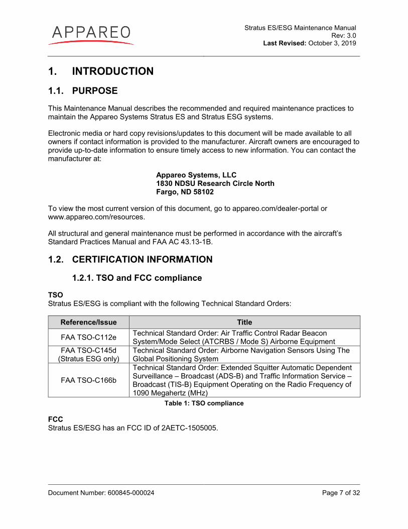
1.2.1. TSO and FCC compliance
TSO Stratus ES/ESG is compliant with the following Technical Standard Orders:
Reference/Issue Title
FAA TSO-C112e Technical Standard Order: Air Traffic Control Radar Beacon System/Mode Select (ATCRBS / Mode S) Airborne Equipment
FAA TSO-C145d (Stratus ESG only)
Technical Standard Order: Airborne Navigation Sensors Using The Global Positioning System
FAA TSO-C166b
Technical Standard Order: Extended Squitter Automatic Dependent Surveillance – Broadcast (ADS-B) and Traffic Information Service – Broadcast (TIS-B) Equipment Operating on the Radio Frequency of 1090 Megahertz (MHz)
Table 1: TSO compliance
FCC Stratus ES/ESG has an FCC ID of 2AETC-1505005.
Stratus ES/ESG Maintenance Manual Rev: 3.0
Last Revised: October 3, 2019
Document Number: 600845-000024 Page 8 of 32
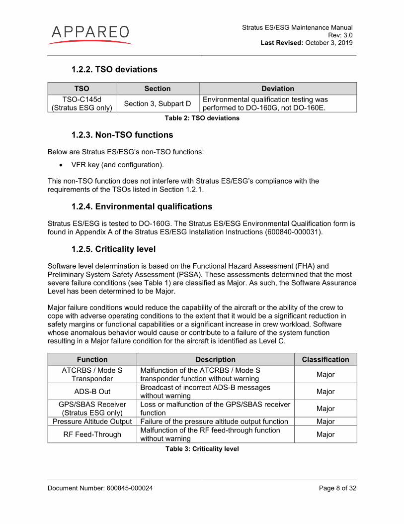
1.2.2. TSO deviations
TSO Section Deviation TSO-C145d
(Stratus ESG only) Section 3, Subpart D Environmental qualification testing was performed to DO-160G, not DO-160E.
Table 2: TSO deviations
1.2.3. Non-TSO functions
Below are Stratus ES/ESG’s non-TSO functions:
• VFR key (and configuration).
This non-TSO function does not interfere with Stratus ES/ESG’s compliance with the requirements of the TSOs listed in Section 1.2.1.
1.2.4. Environmental qualifications
Stratus ES/ESG is tested to DO-160G. The Stratus ES/ESG Environmental Qualification form is found in Appendix A of the Stratus ES/ESG Installation Instructions (600840-000031).
1.2.5. Criticality level
Software level determination is based on the Functional Hazard Assessment (FHA) and Preliminary System Safety Assessment (PSSA). These assessments determined that the most severe failure conditions (see Table 1) are classified as Major. As such, the Software Assurance Level has been determined to be Major.
Major failure conditions would reduce the capability of the aircraft or the ability of the crew to cope with adverse operating conditions to the extent that it would be a significant reduction in safety margins or functional capabilities or a significant increase in crew workload. Software whose anomalous behavior would cause or contribute to a failure of the system function resulting in a Major failure condition for the aircraft is identified as Level C.
Function Description Classification ATCRBS / Mode S
Transponder Malfunction of the ATCRBS / Mode S transponder function without warning Major
ADS-B Out Broadcast of incorrect ADS-B messages without warning Major
GPS/SBAS Receiver (Stratus ESG only)
Loss or malfunction of the GPS/SBAS receiver function Major
Pressure Altitude Output Failure of the pressure altitude output function Major
RF Feed-Through Malfunction of the RF feed-through function without warning Major
Table 3: Criticality level
Stratus ES/ESG Maintenance Manual Rev: 3.0
Last Revised: October 3, 2019
Document Number: 600845-000024 Page 9 of 32
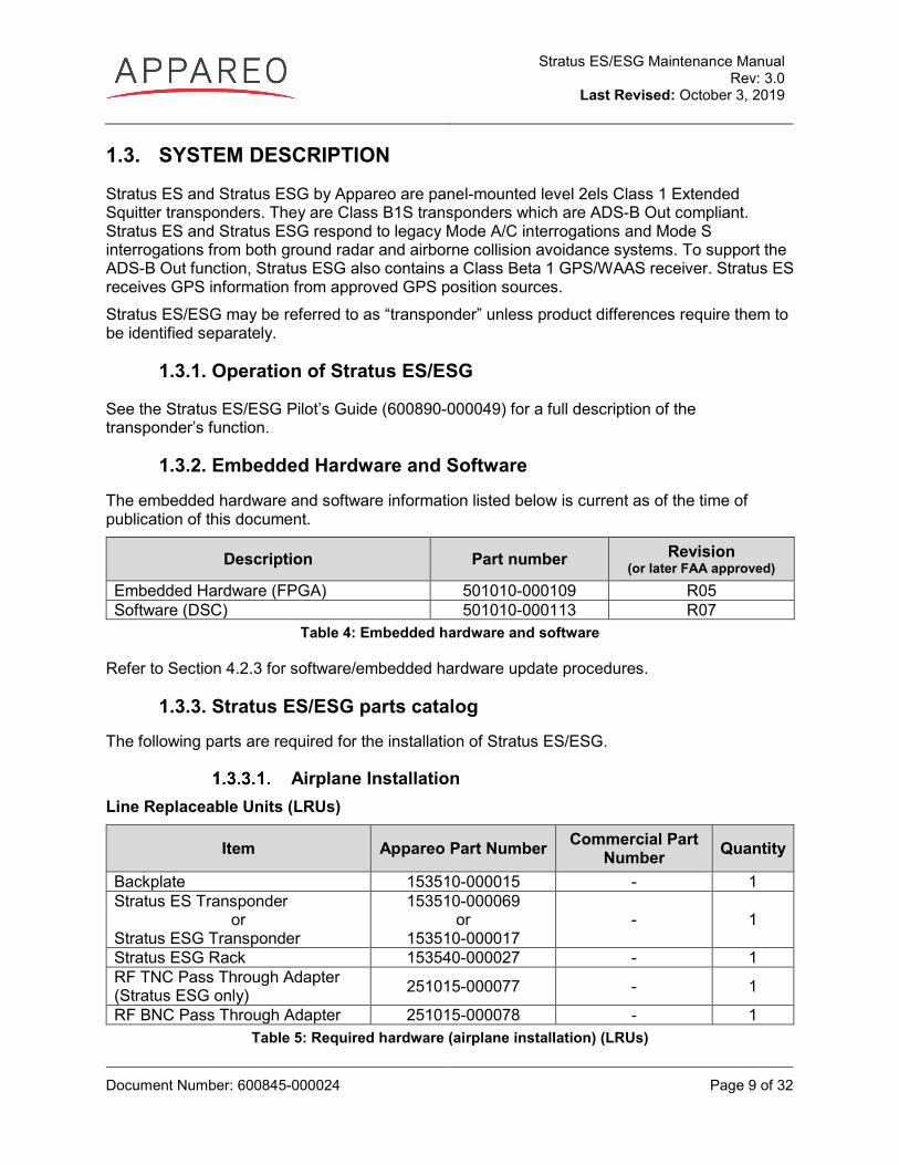
1.3. SYSTEM DESCRIPTION
Stratus ES and Stratus ESG by Appareo are panel-mounted level 2els Class 1 Extended Squitter transponders. They are Class B1S transponders which are ADS-B Out compliant. Stratus ES and Stratus ESG respond to legacy Mode A/C interrogations and Mode S interrogations from both ground radar and airborne collision avoidance systems. To support the ADS-B Out function, Stratus ESG also contains a Class Beta 1 GPS/WAAS receiver. Stratus ES receives GPS information from approved GPS position sources. Stratus ES/ESG may be referred to as “transponder” unless product differences require them to be identified separately.
1.3.1. Operation of Stratus ES/ESG
See the Stratus ES/ESG Pilot’s Guide (600890-000049) for a full description of the transponder’s function.
1.3.2. Embedded Hardware and Software The embedded hardware and software information listed below is current as of the time of publication of this document.
Description Part number Revision (or later FAA approved)
Embedded Hardware (FPGA) 501010-000109 R05 Software (DSC) 501010-000113 R07
Table 4: Embedded hardware and software
Refer to Section 4.2.3 for software/embedded hardware update procedures.
1.3.3. Stratus ES/ESG parts catalog The following parts are required for the installation of Stratus ES/ESG.
Airplane Installation Line Replaceable Units (LRUs)
Item Appareo Part Number Commercial Part Number Quantity
Backplate 153510-000015 - 1 Stratus ES Transponder
or Stratus ESG Transponder
153510-000069 or
153510-000017 - 1
Stratus ESG Rack 153540-000027 - 1 RF TNC Pass Through Adapter (Stratus ESG only) 251015-000077 - 1
RF BNC Pass Through Adapter 251015-000078 - 1 Table 5: Required hardware (airplane installation) (LRUs)
Stratus ES/ESG Maintenance Manual Rev: 3.0
Last Revised: October 3, 2019
Document Number: 600845-000024 Page 10 of 32
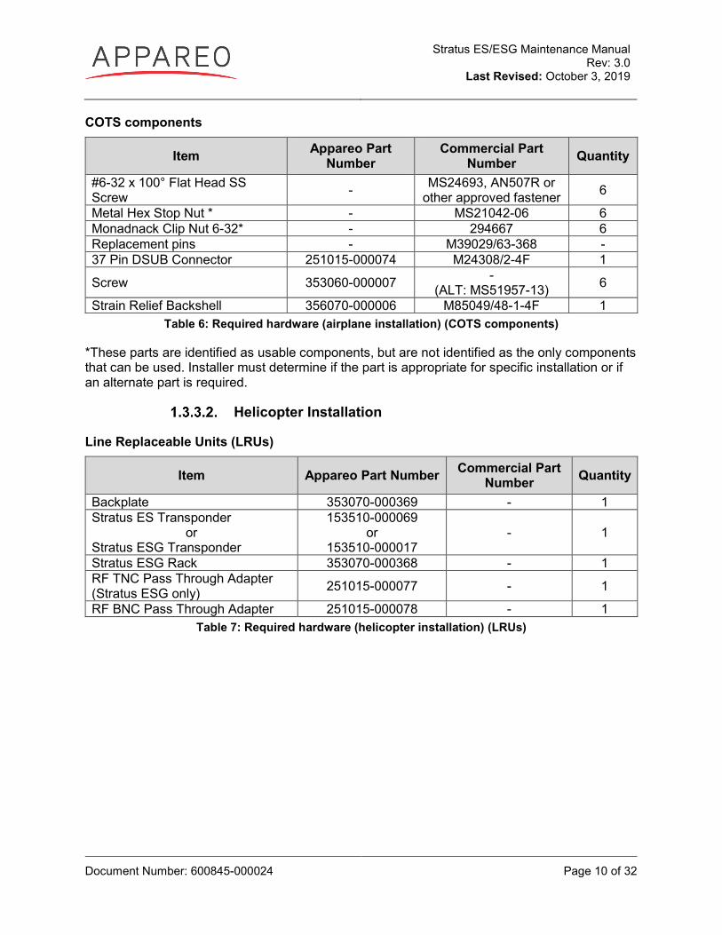
COTS components
Item Appareo Part Number
Commercial Part Number Quantity
#6-32 x 100° Flat Head SS Screw - MS24693, AN507R or
other approved fastener 6
Metal Hex Stop Nut * - MS21042-06 6 Monadnack Clip Nut 6-32* - 294667 6 Replacement pins - M39029/63-368 - 37 Pin DSUB Connector 251015-000074 M24308/2-4F 1
Screw 353060-000007 - (ALT: MS51957-13) 6
Strain Relief Backshell 356070-000006 M85049/48-1-4F 1 Table 6: Required hardware (airplane installation) (COTS components)
*These parts are identified as usable components, but are not identified as the only components that can be used. Installer must determine if the part is appropriate for specific installation or if an alternate part is required.
Helicopter Installation
Line Replaceable Units (LRUs)
Item Appareo Part Number Commercial Part Number Quantity
Backplate 353070-000369 - 1 Stratus ES Transponder
or Stratus ESG Transponder
153510-000069 or
153510-000017 - 1
Stratus ESG Rack 353070-000368 - 1 RF TNC Pass Through Adapter (Stratus ESG only) 251015-000077 - 1
RF BNC Pass Through Adapter 251015-000078 - 1 Table 7: Required hardware (helicopter installation) (LRUs)
Stratus ES/ESG Maintenance Manual Rev: 3.0
Last Revised: October 3, 2019
Document Number: 600845-000024 Page 11 of 32
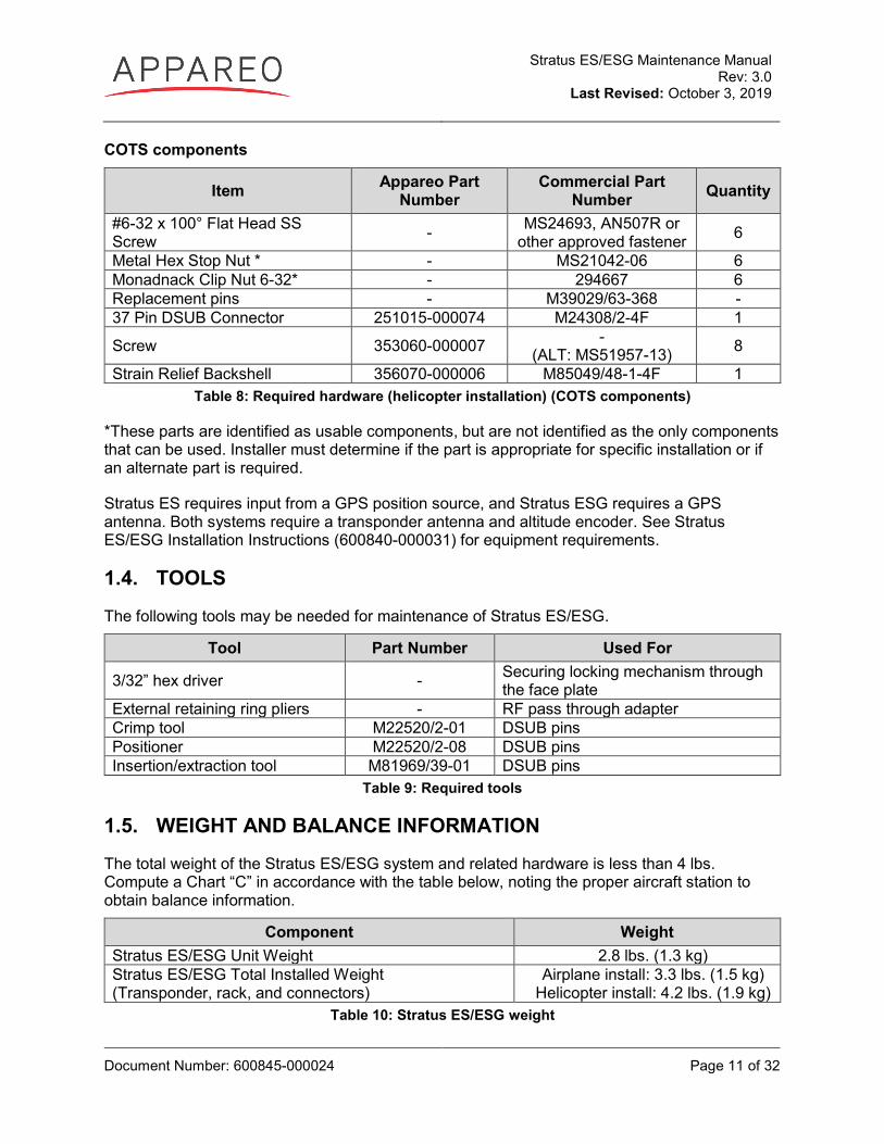
COTS components
Item Appareo Part Number
Commercial Part Number Quantity
#6-32 x 100° Flat Head SS Screw - MS24693, AN507R or
other approved fastener 6
Metal Hex Stop Nut * - MS21042-06 6 Monadnack Clip Nut 6-32* - 294667 6 Replacement pins - M39029/63-368 - 37 Pin DSUB Connector 251015-000074 M24308/2-4F 1
Screw 353060-000007 - (ALT: MS51957-13) 8
Strain Relief Backshell 356070-000006 M85049/48-1-4F 1 Table 8: Required hardware (helicopter installation) (COTS components)
*These parts are identified as usable components, but are not identified as the only components that can be used. Installer must determine if the part is appropriate for specific installation or if an alternate part is required.
Stratus ES requires input from a GPS position source, and Stratus ESG requires a GPS antenna. Both systems require a transponder antenna and altitude encoder. See Stratus ES/ESG Installation Instructions (600840-000031) for equipment requirements.
1.4. TOOLS
The following tools may be needed for maintenance of Stratus ES/ESG.
Tool Part Number Used For
3/32” hex driver - Securing locking mechanism through the face plate
External retaining ring pliers - RF pass through adapter Crimp tool M22520/2-01 DSUB pins Positioner M22520/2-08 DSUB pins Insertion/extraction tool M81969/39-01 DSUB pins
Table 9: Required tools
1.5. WEIGHT AND BALANCE INFORMATION
The total weight of the Stratus ES/ESG system and related hardware is less than 4 lbs. Compute a Chart “C” in accordance with the table below, noting the proper aircraft station to obtain balance information.
Component Weight Stratus ES/ESG Unit Weight 2.8 lbs. (1.3 kg) Stratus ES/ESG Total Installed Weight (Transponder, rack, and connectors)
Airplane install: 3.3 lbs. (1.5 kg) Helicopter install: 4.2 lbs. (1.9 kg)
Table 10: Stratus ES/ESG weight
Stratus ES/ESG Maintenance Manual Rev: 3.0
Last Revised: October 3, 2019
Document Number: 600845-000024 Page 12 of 32
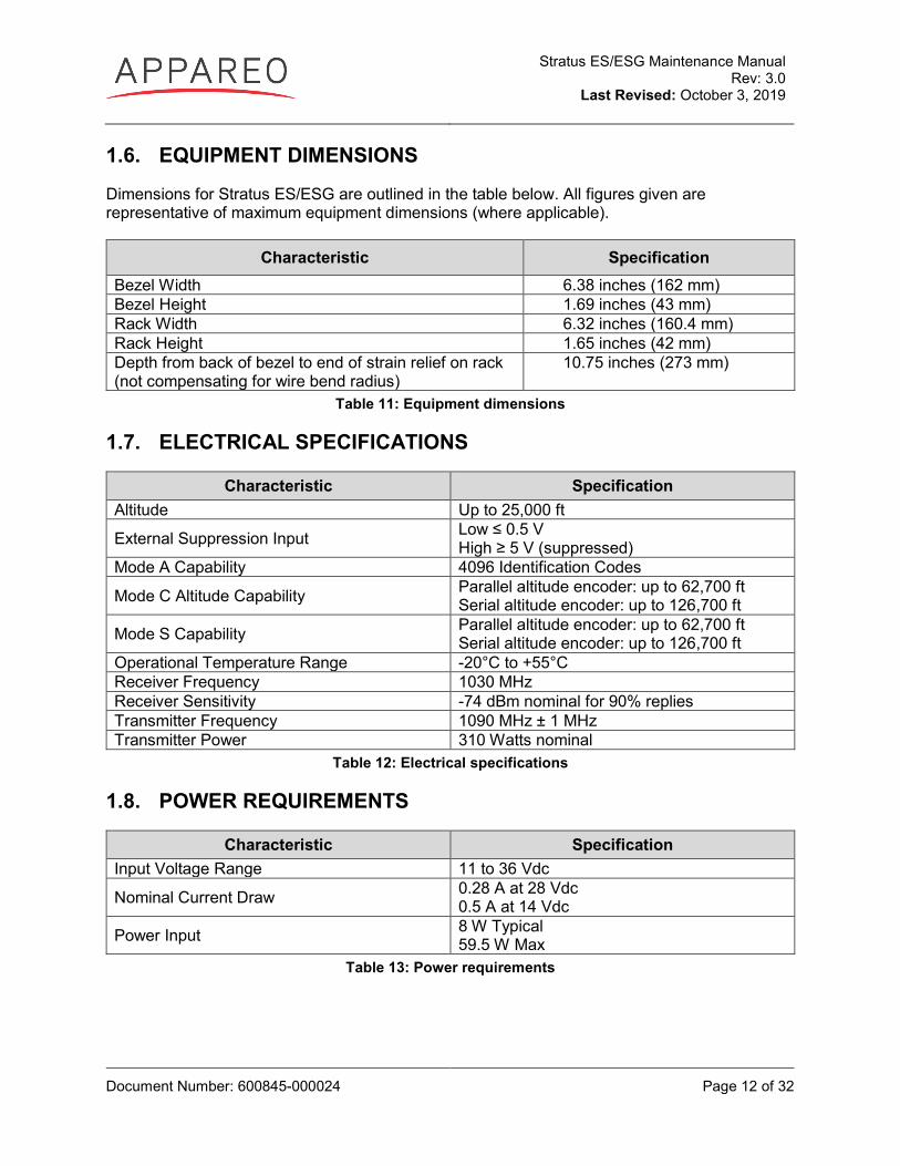
1.6. EQUIPMENT DIMENSIONS
Dimensions for Stratus ES/ESG are outlined in the table below. All figures given are representative of maximum equipment dimensions (where applicable).
Characteristic Specification Bezel Width 6.38 inches (162 mm) Bezel Height 1.69 inches (43 mm) Rack Width 6.32 inches (160.4 mm) Rack Height 1.65 inches (42 mm) Depth from back of bezel to end of strain relief on rack (not compensating for wire bend radius)
10.75 inches (273 mm)
Table 11: Equipment dimensions
1.7. ELECTRICAL SPECIFICATIONS
Characteristic Specification Altitude Up to 25,000 ft
External Suppression Input Low ≤ 0.5 V High ≥ 5 V (suppressed)
Mode A Capability 4096 Identification Codes
Mode C Altitude Capability Parallel altitude encoder: up to 62,700 ft Serial altitude encoder: up to 126,700 ft
Mode S Capability Parallel altitude encoder: up to 62,700 ft Serial altitude encoder: up to 126,700 ft
Operational Temperature Range -20°C to +55°C Receiver Frequency 1030 MHz Receiver Sensitivity -74 dBm nominal for 90% replies Transmitter Frequency 1090 MHz ± 1 MHz Transmitter Power 310 Watts nominal
Table 12: Electrical specifications
1.8. POWER REQUIREMENTS
Characteristic Specification Input Voltage Range 11 to 36 Vdc
Nominal Current Draw 0.28 A at 28 Vdc 0.5 A at 14 Vdc
Power Input 8 W Typical 59.5 W Max
Table 13: Power requirements
Stratus ES/ESG Maintenance Manual Rev: 3.0
Last Revised: October 3, 2019
Document Number: 600845-000024 Page 13 of 32
2. AIRWORTHINESS LIMITATIONS This Airworthiness Limitations section is FAA approved and specifies inspections and other maintenance required under §43.16 and §91.403 of the Federal Aviation Regulations unless an alternate program has been FAA approved.
There are no airworthiness limitations associated with this type design change.
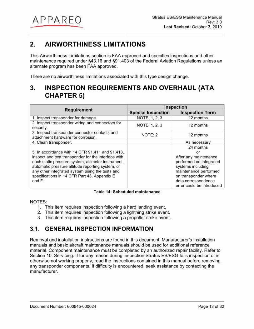
3. INSPECTION REQUIREMENTS AND OVERHAUL (ATA CHAPTER 5)
Requirement Inspection Special Inspection Inspection Term
1. Inspect transponder for damage. NOTE: 1, 2, 3 12 months 2. Inspect transponder wiring and connectors for security. NOTE: 1, 2, 3 12 months
3. Inspect transponder connector contacts and attachment hardware for corrosion. NOTE: 2 12 months
4. Clean transponder. As necessary
5. In accordance with 14 CFR 91.411 and 91.413, inspect and test transponder for the interface with each static pressure system, altimeter instrument, automatic pressure altitude reporting system, or any other integrated system using the tests and specifications in 14 CFR Part 43, Appendix E and F.
24 months or
After any maintenance performed on integrated systems including maintenance performed on transponder where data correspondence error could be introduced
Table 14: Scheduled maintenance
NOTES: 1. This item requires inspection following a hard landing event. 2. This item requires inspection following a lightning strike event. 3. This item requires inspection following a propeller strike event.
3.1. GENERAL INSPECTION INFORMATION
Removal and installation instructions are found in this document. Manufacturer’s installation manuals and basic aircraft maintenance manuals should be used for additional reference material. Component maintenance must be completed by an authorized repair facility. Refer to Section 10: Servicing. If for any reason during inspection Stratus ES/ESG fails inspection or is otherwise not working properly, read the instructions contained in this manual before removing any transponder components. If difficulty is encountered, seek assistance by contacting the manufacturer.
Stratus ES/ESG Maintenance Manual Rev: 3.0
Last Revised: October 3, 2019
Document Number: 600845-000024 Page 14 of 32
4. DIMENSIONS AND ACCESS (ATA CHAPTER 6) 4.1. COMPONENT LOCATIONS
Stratus ES/ESG: Stratus ES/ESG is panel mounted.
GPS position source (Stratus ES): Compatible GPS position sources are panel mounted.
GPS antenna (Stratus ESG): Typical GPS antenna installation locations are on the top of the aircraft or on the empennage with consideration for line of sight with satellites.
Transponder antenna: The transponder antenna should be mounted vertically on the bottom of the aircraft.
Altitude encoder: The altitude encoder should be installed using the manufacturer’s instructions and recommendations.
4.2. MAINTENANCE INSTRUCTIONS
The following instructions are in addition to the standard practices used to maintain the aircraft structure, the wiring described in the aircraft manufacturer’s maintenance manual, and FAA Advisory Circular 43.13-1B.
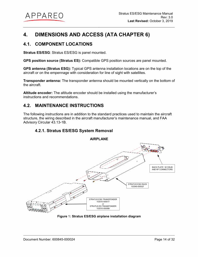
4.2.1. Stratus ES/ESG System Removal
AIRPLANE
STRATUS ESG TRANSPONDER153510-000017
orSTRATUS ES TRANSPONDER
153510-000069
STRATUS ESG RACK153540-000027
BACK PLATE W/ DSUB AND RF CONNECTORS
Figure 1: Stratus ES/ESG airplane installation diagram
Stratus ES/ESG Maintenance Manual Rev: 3.0
Last Revised: October 3, 2019
Document Number: 600845-000024 Page 15 of 32
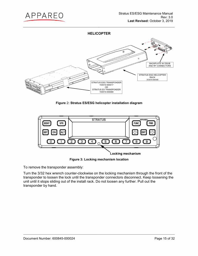
HELICOPTER
BACKPLATE W/ DSUB AND RF CONNECTORS
STRATUS ESG TRANSPONDER153510-000017
ORSTRATUS ES TRANSPONDER
153510-000069
STRATUS ESG HELCOPTER RACK
353070-000368
Figure 2: Stratus ES/ESG helicopter installation diagram
Figure 3: Locking mechanism location
To remove the transponder assembly: Turn the 3/32 hex wrench counter-clockwise on the locking mechanism through the front of the transponder to loosen the lock until the transponder connectors disconnect. Keep loosening the unit until it stops sliding out of the install rack. Do not loosen any further. Pull out the transponder by hand.
Stratus ES/ESG Maintenance Manual Rev: 3.0
Last Revised: October 3, 2019
Document Number: 600845-000024 Page 16 of 32
4.2.2. Stratus ES/ESG System Replacement
To replace the transponder assembly: 1. Adjust the locking mechanism on the transponder using a 3/32 hex wrench so that the
front lobe is in a vertical position. Insert the unit by hand until it comes to a stop. This occurs when the front lobe contacts the clearance slot of the install rack.
2. Tighten the locking mechanism with the 3/32 hex wrench until it is tight and the connectors have mated. Do not overtighten. If the mechanism will not tighten, verify that the transponder is properly seated in the rack. The unit is fully seated when the unit does not move back when tightening the locking mechanism.
NOTE: Ensure that the transponder is seated as far back as possible against the backplate so that there is a secure connection between the transponder and the connectors.
NOTE: Conduct the applicable functional tests in Section 4.3 after replacing the transponder assembly.
4.2.3. Software Update
The following equipment is required to perform a software update:
• Portable computer with Windows operating system • Stratus ES/ESG Software Update Tool desktop software (See Step 4) • Stratus ES/ESG software/embedded hardware update (See Step 4) • 3 amp power supply • D-sub wiring harness • Serial to USB adapter (optional)
Stratus ES/ESG Maintenance Manual Rev: 3.0
Last Revised: October 3, 2019
Document Number: 600845-000024 Page 17 of 32
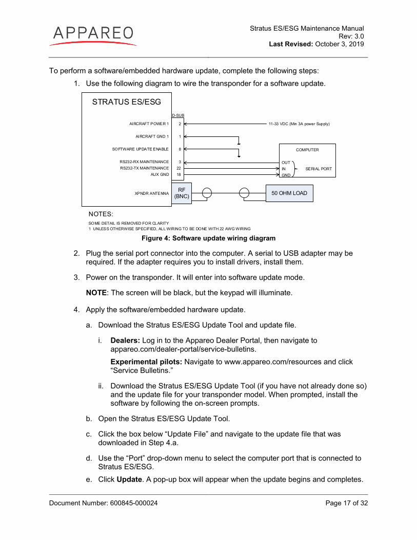
To perform a software/embedded hardware update, complete the following steps: 1. Use the following diagram to wire the transponder for a software update.
NOTES:SOME DETAIL IS REMOVED FOR CLARITY1 UNLESS OTHERWISE SPECIFIED, ALL WIRING TO BE DONE WITH 22 AWG WIRING
STRATUS ES/ESG
AIRCRAFT POWER 1
AIRCRAFT GND 1
SOFTWARE UPDATE ENABLE
RS232-RX MAINTENANCERS232-TX MAINTENANCE
AUX GND
XPNDR ANTENNA
2
1
8
32218
11-33 VDC (Min 3A power Supply)
COMPUTER
OUTIN SERIAL PORTGND
D-SUB
RF(BNC) 50 OHM LOAD
Figure 4: Software update wiring diagram
2. Plug the serial port connector into the computer. A serial to USB adapter may be required. If the adapter requires you to install drivers, install them.
3. Power on the transponder. It will enter into software update mode.
NOTE: The screen will be black, but the keypad will illuminate.
4. Apply the software/embedded hardware update.
a. Download the Stratus ES/ESG Update Tool and update file.
i. Dealers: Log in to the Appareo Dealer Portal, then navigate to appareo.com/dealer-portal/service-bulletins. Experimental pilots: Navigate to www.appareo.com/resources and click “Service Bulletins.”
ii. Download the Stratus ES/ESG Update Tool (if you have not already done so) and the update file for your transponder model. When prompted, install the software by following the on-screen prompts.
b. Open the Stratus ES/ESG Update Tool.
c. Click the box below “Update File” and navigate to the update file that was downloaded in Step 4.a.
d. Use the “Port” drop-down menu to select the computer port that is connected to Stratus ES/ESG.
e. Click Update. A pop-up box will appear when the update begins and completes.
Stratus ES/ESG Maintenance Manual Rev: 3.0
Last Revised: October 3, 2019
Document Number: 600845-000024 Page 18 of 32
5. Verify that the software/embedded hardware update has applied correctly.
a. Remove the grounding pin (pin 8).
b. Turn off Stratus ES/ESG and enter into configuration mode (while holding the FUNC key, press and release the PWR key).
c. Press FUNC or the arrow keys to advance to the software versions diagnostic screens and verify that the most recent programmed configuration appears. Refer to the service bulletin alerting you of the software update for the most recent programmed configuration.
4.2.4. Stratus ES/ESG Configuration
See Stratus ES/ESG Installation Instructions (600840-000031) for instructions for how to configure the transponder if a replacement has been installed or the unit is new to this aircraft.
4.3. FUNCTIONAL TESTS
When installed in accordance with these installation instructions, Stratus ES/ESG complies with 14 CFR Part 91.227.
Final installation checks for Stratus ES/ESG are the responsibility of the installer. The installer must ensure that the transponder is installed on an aircraft that coincides with the approval given within the testing performed for the TSOs held by this device (TSO-C112e, TSO-C145d (Stratus ESG only), and TSO-C166b). Refer to Appendix A of the Stratus ES/ESG Installation Instructions (600840-000031).
After installation is complete, verify operation as identified in 14 CFR Part 43, Appendix F. The IFR6000 with OPT3 (manufactured by Cobham AvComm – formerly Aeroflex Test Solutions) or equivalent test set can be used to determine compliance.
Additional information about compliance testing can be found in Chapter 4 of Advisory Circular (AC) 20-165B.
When installed correctly, Stratus ES/ESG complies with 14 CFR Part 91.215 & 91.225. While in airspace specified in 14 CFR Part 91.215, Stratus ES/ESG must be maintained to 14 CFR Part 91.413.
In addition to maintaining compliance to the regulations above, perform the following operational tests after configuration. Depending on the maintenance performed, an EMI test might also be required. See Stratus ES/ESG Installation Instructions (600840-000031) for EMI test procedures.
NOTE: Tests should be executed in an area where the aircraft has an unimpeded view of the sky, such that a proper GPS fix can be established.
Stratus ES/ESG Maintenance Manual Rev: 3.0
Last Revised: October 3, 2019
Document Number: 600845-000024 Page 19 of 32
4.3.1. Power bus
Turn on the power to the aircraft. Verify that the unit powers on.
4.3.2. Discrete inputs
NOTE: Depending on the installation, the functional tests for the following discrete inputs are optional.
1. Turn off the transponder and enter into configuration mode on the transponder (while holding the FUNC key, press and release the PWR key).
2. Press FUNC or the arrow keys to advance to the external input diagnostics screen. The screen displays the real-time state of the external standby, external IDENT, and squat switch inputs.
3. Activate and deactivate each discrete input and verify that the proper state is reflected on the display.
• External standby: Ground each transponder’s external standby pin and verify that the state is “inactive.”
• External IDENT: Activate the external switch and verify that the state is “active.”
• Squat switch: Activate the squat switch and verify that the correct state is shown.
4.3.3. Analog inputs
1. Enter into configuration mode on the transponder.
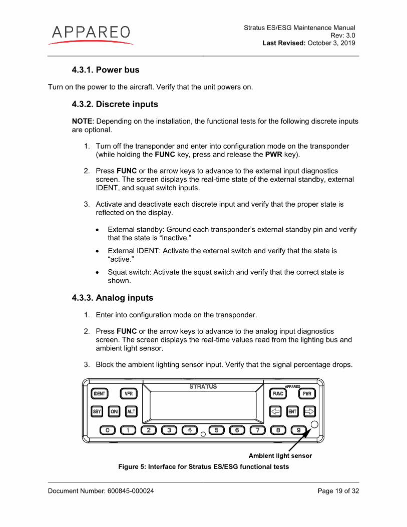
2. Press FUNC or the arrow keys to advance to the analog input diagnostics screen. The screen displays the real-time values read from the lighting bus and ambient light sensor.
3. Block the ambient lighting sensor input. Verify that the signal percentage drops.
Figure 5: Interface for Stratus ES/ESG functional tests
Stratus ES/ESG Maintenance Manual Rev: 3.0
Last Revised: October 3, 2019
Document Number: 600845-000024 Page 20 of 32
4. Shine a light on the ambient light sensor. Verify that the signal percentage increases.
5. If you are using the 14V or 28V lighting bus: Adjust the lighting bus input to minimum. Verify that the displayed value is 0%.
6. If you are using the 14V or 28V lighting bus: Adjust the lighting bus input to maximum. Verify that the displayed value is 100%.
4.3.4. GPS position source (Stratus ES)
1. Enter into configuration mode on Stratus ES.
2. Press FUNC or the arrow keys to advance to the GPS receiver diagnostic screen.
3. Verify that the NIC value, latitude, and longitude are all non-zero numbers.
4.3.5. GPS antenna (Stratus ESG)
1. Turn off all avionics except Stratus ESG.
2. Enter into configuration mode on Stratus ESG.
3. Press FUNC or the arrow keys to advance to the GPS receiver diagnostic screen and wait until the NIC value is a non-zero number.
4. Turn on one avionic at a time. Verify that the NIC value does not drop below 7.
4.3.6. Altitude encoder
1. Enter into configuration mode on Stratus ES/ESG.
2. Press FUNC or the arrow keys to advance to the altitude diagnostic screen.
3. Verify that the altitude displayed is correct to your geographic location.

Stratus ES/ESG Maintenance Manual Rev: 3.0
Last Revised: October 3, 2019
Document Number: 600845-000024 Page 21 of 32
4.3.7. ADS-B Out Verification
The aircraft requires an unimpeded view of the sky for GPS reception; otherwise, a GPS repeater will be required. Using the transponder test set, perform an AC20-165 air test.
1. Power on the transponder.
2. The transponder will enter into GND mode. Press ALT.
NOTE: Coordination with ATC may be required depending on location of facility.
3. Verify the following ADS-B out parameters using the transponder test set:
- NIC ≥ 7 - NACp ≥ 8
- NACv ≥ 1 - SIL ≥ 3 - SDA ≥ 2
5. LIFTING AND SHORING (ATA CHAPTER 7) 5.1. LIFTING INFORMATION
5.1.1. Jacking Information
No change to basic aircraft Instructions for Continued Airworthiness (Maintenance Manuals)
5.1.2. Lifting Information
No change to basic aircraft Instructions for Continued Airworthiness (Maintenance Manuals)
5.2. SHORING INFORMATION
No change to basic aircraft Instructions for Continued Airworthiness (Maintenance Manuals)
6. LEVELING AND WEIGHING (ATA CHAPTER 8) 6.1. LEVELING INFORMATION
No change to basic aircraft Instructions for Continued Airworthiness (Maintenance Manuals)
6.2. WEIGHING INFORMATION
No change to basic aircraft Instructions for Continued Airworthiness (Maintenance Manuals)
Stratus ES/ESG Maintenance Manual Rev: 3.0
Last Revised: October 3, 2019
Document Number: 600845-000024 Page 22 of 32
7. TOWING AND TAXIING (ATA CHAPTER 9) 7.1. TOW INSTRUCTIONS
No change to basic aircraft Instructions for Continued Airworthiness (Maintenance Manuals)
7.2. TAXIING INSTRUCTIONS
No change to basic aircraft Instructions for Continued Airworthiness (Maintenance Manuals)
8. PARKING, MOORING AND STORAGE (ATA CHAPTER 10)
8.1. MOORING INFORMATION
No change to basic aircraft Instructions for Continued Airworthiness (Maintenance Manuals)
8.2. PARKING INFORMATION
No change to basic aircraft Instructions for Continued Airworthiness (Maintenance Manuals)
8.3. STORAGE LIMITATIONS
No change to basic aircraft Instructions for Continued Airworthiness (Maintenance Manuals)
9. PLACARDS AND MARKINGS (ATA CHAPTER 11) Ensure that the labeling is in accordance with AC 43.13-2B, Chapter 2, Section 207, Sub-Section f., Paragraph (4).
Stratus ES/ESG Maintenance Manual Rev: 3.0
Last Revised: October 3, 2019
Document Number: 600845-000024 Page 23 of 32
10. SERVICING (ATA CHAPTER 12) 10.1. SERVICING INFORMATION
The Stratus ES/ESG system has a number of internal self-test features. See Section 10.1.2 for a troubleshooting guide.
10.1.1. Component Repair
Equipment determined in need of repair must be returned to a properly rated repair facility that is trained and qualified. Appareo provides repair services and has an authorized repair station.
To utilize Appareo's repair services, contact Appareo support for a Return Merchandise Authorization (RMA) number. Return all defective and suspected defective components to the following address for repair and replacement.
Appareo Systems, LLC Attn: [RMA Number] 1830 NDSU Research Circle North Fargo, ND 58102
For additional information, contact Appareo Systems at +1-701-356-2200.
Stratus ES/ESG Maintenance Manual Rev: 3.0
Last Revised: October 3, 2019
Document Number: 600845-000024 Page 24 of 32
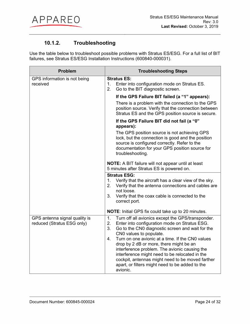
10.1.2. Troubleshooting
Use the table below to troubleshoot possible problems with Stratus ES/ESG. For a full list of BIT failures, see Stratus ES/ESG Installation Instructions (600840-000031).
Problem Troubleshooting Steps GPS information is not being received
Stratus ES: 1. Enter into configuration mode on Stratus ES. 2. Go to the BIT diagnostic screen.
If the GPS Failure BIT failed (a “1” appears): There is a problem with the connection to the GPS position source. Verify that the connection between Stratus ES and the GPS position source is secure. If the GPS Failure BIT did not fail (a “0” appears): The GPS position source is not achieving GPS lock, but the connection is good and the position source is configured correctly. Refer to the documentation for your GPS position source for troubleshooting.
NOTE: A BIT failure will not appear until at least 5 minutes after Stratus ES is powered on. Stratus ESG: 1. Verify that the aircraft has a clear view of the sky. 2. Verify that the antenna connections and cables are
not loose. 3. Verify that the coax cable is connected to the
correct port. NOTE: Initial GPS fix could take up to 20 minutes.
GPS antenna signal quality is reduced (Stratus ESG only)
1. Turn off all avionics except the GPS/transponder. 2. Enter into configuration mode on Stratus ESG. 3. Go to the CN0 diagnostic screen and wait for the
CN0 values to populate. 4. Turn on one avionic at a time. If the CN0 values
drop by 2 dB or more, there might be an interference problem. The avionic causing the interference might need to be relocated in the cockpit, antennas might need to be moved farther apart, or filters might need to be added to the avionic.
Stratus ES/ESG Maintenance Manual Rev: 3.0
Last Revised: October 3, 2019
Document Number: 600845-000024 Page 25 of 32
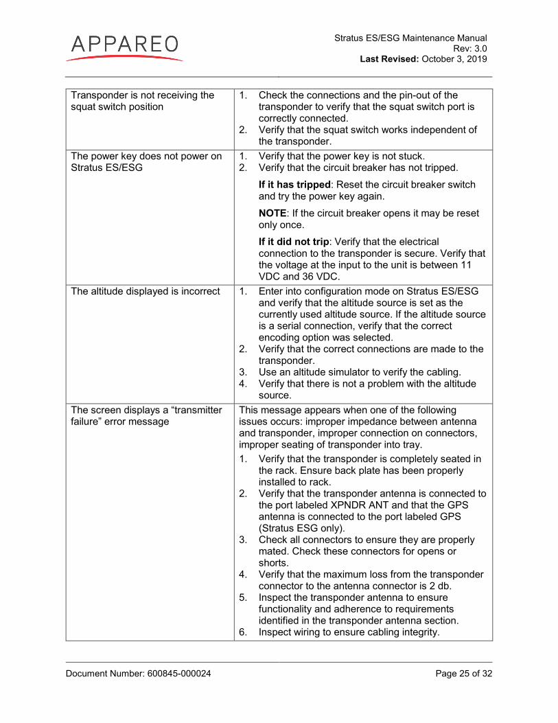
Transponder is not receiving the squat switch position
1. Check the connections and the pin-out of the transponder to verify that the squat switch port is correctly connected.
2. Verify that the squat switch works independent of the transponder.
The power key does not power on Stratus ES/ESG
1. Verify that the power key is not stuck. 2. Verify that the circuit breaker has not tripped.
If it has tripped: Reset the circuit breaker switch and try the power key again. NOTE: If the circuit breaker opens it may be reset only once. If it did not trip: Verify that the electrical connection to the transponder is secure. Verify that the voltage at the input to the unit is between 11 VDC and 36 VDC.
The altitude displayed is incorrect 1. Enter into configuration mode on Stratus ES/ESG and verify that the altitude source is set as the currently used altitude source. If the altitude source is a serial connection, verify that the correct encoding option was selected.
2. Verify that the correct connections are made to the transponder.
3. Use an altitude simulator to verify the cabling. 4. Verify that there is not a problem with the altitude
source. The screen displays a “transmitter failure” error message
This message appears when one of the following issues occurs: improper impedance between antenna and transponder, improper connection on connectors, improper seating of transponder into tray. 1. Verify that the transponder is completely seated in
the rack. Ensure back plate has been properly installed to rack.
2. Verify that the transponder antenna is connected to the port labeled XPNDR ANT and that the GPS antenna is connected to the port labeled GPS (Stratus ESG only).
3. Check all connectors to ensure they are properly mated. Check these connectors for opens or shorts.
4. Verify that the maximum loss from the transponder connector to the antenna connector is 2 db.
5. Inspect the transponder antenna to ensure functionality and adherence to requirements identified in the transponder antenna section.
6. Inspect wiring to ensure cabling integrity.
Stratus ES/ESG Maintenance Manual Rev: 3.0
Last Revised: October 3, 2019
Document Number: 600845-000024 Page 26 of 32
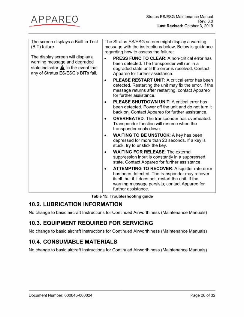
The screen displays a Built in Test (BIT) failure The display screen will display a warning message and degraded state indicator in the event that any of Stratus ES/ESG’s BITs fail.
The Stratus ES/ESG screen might display a warning message with the instructions below. Below is guidance regarding how to assess the failure: • PRESS FUNC TO CLEAR: A non-critical error has
been detected. The transponder will run in a degraded state until the error is resolved. Contact Appareo for further assistance.
• PLEASE RESTART UNIT: A critical error has been detected. Restarting the unit may fix the error. If the message returns after restarting, contact Appareo for further assistance.
• PLEASE SHUTDOWN UNIT: A critical error has been detected. Power off the unit and do not turn it back on. Contact Appareo for further assistance.
• OVERHEATED: The transponder has overheated. Transponder function will resume when the transponder cools down.
• WAITING TO BE UNSTUCK: A key has been depressed for more than 20 seconds. If a key is stuck, try to unstick the key.
• WAITING FOR RELEASE: The external suppression input is constantly in a suppressed state. Contact Appareo for further assistance.
• ATTEMPTING TO RECOVER: A squitter rate error has been detected. The transponder may recover itself, but if it does not, restart the unit. If the warning message persists, contact Appareo for further assistance.
Table 15: Troubleshooting guide
10.2. LUBRICATION INFORMATION No change to basic aircraft Instructions for Continued Airworthiness (Maintenance Manuals)
10.3. EQUIPMENT REQUIRED FOR SERVICING No change to basic aircraft Instructions for Continued Airworthiness (Maintenance Manuals)
10.4. CONSUMABLE MATERIALS No change to basic aircraft Instructions for Continued Airworthiness (Maintenance Manuals)
Stratus ES/ESG Maintenance Manual Rev: 3.0
Last Revised: October 3, 2019
Document Number: 600845-000024 Page 27 of 32
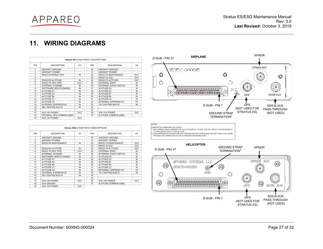
11. WIRING DIAGRAMS
NOTES:
SOME DETAIL IS REMOVED FOR CLARITY1 MAX CURRENT DRAW COMBINED FOR AUX +5V POWER IS 1.25 AMP. THIS WILL RESULT IN AN INCREASE OF 0.25 AMP @28VDC AND 0.47 AMP @ 14VDC2 BOND IMPENDENCE BETWEEN AIRCRAFT GROUND AND UNIT CHASSIS MUST BE LESS THAN 2.5 MILLIOHMS. PROVIDED FOR TERMINATION IS A #4-40 THREADED GROUNDING POINT.
PIN DESCRIPTION I/O
1 AIRCRAFT GROUND2 AIRCRAFT POWER3 RS232 EXTERNAL GPS IN4 -5 RS232-RX ALTITUDE IN6 RS232-TX GPS 1PPS OUT7 EXTERNAL STANDBY IN8 SOFTWARE UPDATE ENABLE IN9 ALTITUDE A1 IN
10 ALTITUDE A4 IN11 ALTITUDE B2 IN12 ALTITUDE C1 IN13 ALTITUDE C4 IN14 EXTERNAL SUPPRESS IN IN15 28V LIGHTING BUS HI IN16 -17 AUX +5V POWER OUT18 EXTERNAL GPS COMMON (GND)19 AUX +5V POWER OUT
PIN
202122232425262728293031323334353637
DESCRIPTION I/O
AIRCRAFT GROUNDAIRCRAFT POWERRS232-TX MAINTENANCE OUTRS232-TX AUX OUTRS232-TX ALTITUDE OUTEXTERNAL IDENT INEXTERNAL SQUAT SWITCH INALTITUDE D4 INALTITUDE A2 INALTITUDE B1 INALTITUDE B4 INALTITUDE C2 INEXTERNAL SUPPRESS I/O I/O14V LIGHTING BUS HI IN-- AUX +5V POWER OUTALTITUDE COMMON (GND)
Stratus ES D-SUB PINOUT DESCRIPTIONS
PIN DESCRIPTION I/O
1 AIRCRAFT GROUND2 AIRCRAFT POWER3 RS232-RX MAINTENANCE IN4 -5 RS232-RX ALTITUDE IN6 RS232-TX GPS 1PPS OUT7 EXTERNAL STANDBY IN8 SOFTWARE UPDATE ENABLE IN9 ALTITUDE A1 IN
10 ALTITUDE A4 IN11 ALTITUDE B2 IN12 ALTITUDE C1 IN13 ALTITUDE C4 IN14 EXTERNAL SUPPRESS IN IN15 28V LIGHTING BUS HI IN16 -17 AUX +5V POWER OUT18 AUX GROUND19 AUX +5V POWER OUT
PIN
202122232425262728293031323334353637
DESCRIPTION I/O
AIRCRAFT GROUNDAIRCRAFT POWERRS232-TX MAINTENANCE OUTRS232-TX AUX OUTRS232-TX ALTITUDE OUTEXTERNAL IDENT INEXTERNAL SQUAT SWITCH INALTITUDE D4 INALTITUDE A2 INALTITUDE B1 INALTITUDE B4 INALTITUDE C2 INEXTERNAL SUPPRESS I/O I/O14V LIGHTING BUS HI IN-- AUX +5V POWER OUTALTITUDE COMMON (GND)
Stratus ESG D-SUB PINOUT DESCRIPTIONS
HELICOPTERXPNDR D-SUB - PIN 37
GROUND STRAP TERMINATION2
D-SUB - PIN 1 GPS(NOT USED FOR
STRATUS ES)
ADS-B AUX PASS-THROUGH
(NOT USED)
AIRPLANE XPNDR D-SUB - PIN 37
ADSB AUXGPS
XPNDR ANT
GROUND STRAP TERMINATION2
D-SUB - PIN 1 GPS(NOT USED FOR
STRATUS ES)
ADS-B AUX PASS-THROUGH
(NOT USED)
Stratus ES/ESG Maintenance Manual Rev: 3.0
Last Revised: October 3, 2019
Document Number: 600845-000024 Page 28 of 32
Figure 6: Pin-out
Stratus ES/ESG Maintenance Manual Rev: 3.0
Last Revised: October 3, 2019
Document Number: 600845-000024 Page 29 of 32
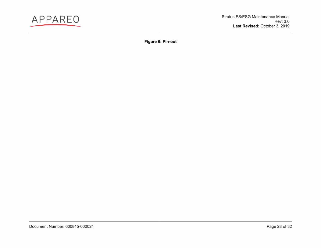
Typical Stratus ES Interconnect (Parallel Altitude Encoder)
NOTES:SOME DETAIL IS REMOVED FOR CLARITY1 UNLESS OTHERWISE SPECIFIED, ALL WIRING TO BE DONE WITH 22 AWG WIRING2 DRAWING DEPICTS INSTALLATION WITH A PARALLEL ALTITUDE ENCODER. SEE PAGE 26 FOR SERIAL ENCODER WIRING3 PIN 24 (RS232 TX ALTITUDE) CAN BE USED AS A SERIAL ALTITUDE SOURCE FOR OTHER EQUIPMENT 4 FROM SPLICE TO UNIT, WIRE LENGTH SHOULD NOT EXCEED 6 INCHES5 CONNECT ONLY 1 INPUT TO LIGHTING BUS- TO CONTROL BRIGHTNESS WITH THE AMBIENT LIGHT SENSOR, DO NOT CONNECT THESE PINS AND SELECT THE AMBIENT LIGHT SENSOR DURING BACKLIGHT SOURCE CONFIGURATION6 ONLY ONE SUPPRESSION SOURCE MAY BE CONNECTED AT ONE TIME (OPTIONAL)7 APPROVED EXTERNAL GPS SOURCES ARE: GARMIN 430W/530W, GARMIN 650/750, & AVIDYNE IFD440/IFD540. SEE INSTALLATION INSTRUCTIONS SECTION 1.11.1 FOR ADDITIONAL DETAILS8 OPTIONAL INSTALLATION. TYPICALLY CONNECTED TO WEIGHT ON WHEELS SWITCH. REFER TO AIRCRAFT MANUAL TO DETERMINE APPLICABILITY. 9 USING RG400, THE MAXIMUM CABLE LENGTH IS 14 FEET WITH A MAXIMUM OF 2 dB LOSS. IF THE INSTALLATION REQUIRES MORE LENGTH, SELECT OTHER 50 OHM COAX THAT WILL PROVIDE A MAXIMUM 2 dB LOSS.
STRATUS ES
AIRCRAFT POWER 1AIRCRAFT POWER 2
AIRCRAFT GROUND 1AIRCRAFT GROUND 2
28V LIGHTING BUS HI14V LIGHTING BUS HI
EXTERNAL STANDBY
EXTERNAL SUPPRESS INEXTERNAL SUPPRESS I/0
RS232 EXTERNAL GPSEXTERNAL GPS COMMON (GND)
EXTERNAL IDENTEXTERNAL SQUAT SWITCH
ALTITUDE A1ALTITUDE A4ALTITUDE B2ALTITUDE C1ALTITUDE C4ALTITUDE D4ALTITUDE A2ALTITUDE B1ALTITUDE B4ALTITUDE C2
ALTITUDE COMMON (GND)
XPNDR ANTENNA
GPS ANTENNA IN(STRATUS ESG ONLY)
AUX PASS-THRU(NOT USED)
221
120
1533
7
1432
318
2526
9101112132728293031
37
11-33 VDC AIRCRAFT POWER
D-SUB
5A
TO LIGHT DIMMING BUS
PARALLEL ALTITUDE ENCODER
MUTUAL SUPPRESSION (ARINC 709)DME
TRANSPONDER 2OPTIONAL
RF(BNC)
XPNDR ANTENNA
RF(TNC)
6
ALTITUDE COMMON (GND)
RF
IDENT INPUTOPTIONAL
WoW
4
4
5
8
9
7GPS SOURCE
RS232 OUTCOMMON GROUND
Figure 7: Stratus ES wiring diagram with parallel altitude encoder
Stratus ES/ESG Maintenance Manual Rev: 3.0
Last Revised: October 3, 2019
Document Number: 600845-000024 Page 30 of 32
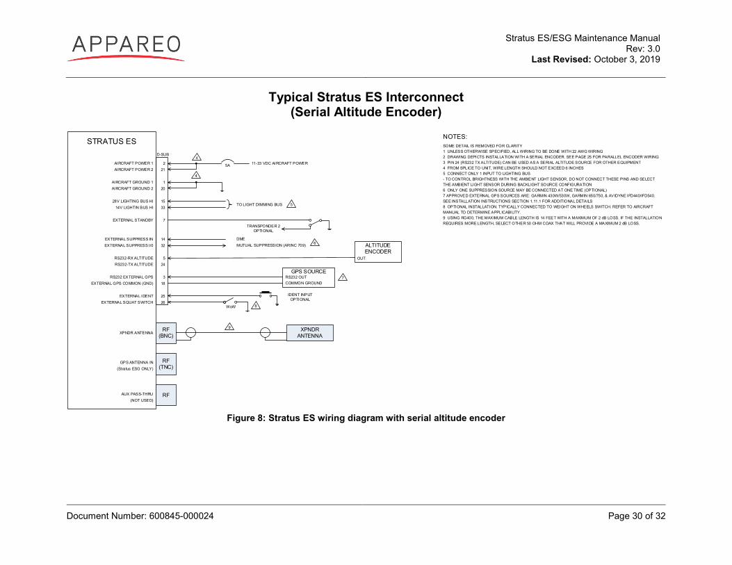
Typical Stratus ES Interconnect (Serial Altitude Encoder)
STRATUS ES
AIRCRAFT POWER 1AIRCRAFT POWER 2
AIRCRAFT GROUND 1AIRCRAFT GROUND 2
28V LIGHTING BUS HI14V LIGHTIN BUS HI
EXTERNAL STANDBY
EXTERNAL SUPPRESS INEXTERNAL SUPPRESS I/0
RS232-RX ALTITUDERS232-TX ALTITUDE
RS232 EXTERNAL GPSEXTERNAL GPS COMMON (GND)
EXTERNAL IDENTEXTERNAL SQUAT SWITCH
XPNDR ANTENNA
GPS ANTENNA IN(Stratus ESG ONLY)
AUX PASS-THRU(NOT USED)
221
120
1533
7
1432
524
318
2526
11-33 VDC AIRCRAFT POWER
D-SUB
5A
MUTUAL SUPPRESSION (ARINC 709)DME
XPNDR ANTENNA
ALTITUDE ENCODER
OUT
6
RF(BNC)
RF(TNC)
RF
TO LIGHT DIMMING BUS
8
IDENT INPUTOPTIONAL
WoW
NOTES:SOME DETAIL IS REMOVED FOR CLARITY1 UNLESS OTHERWISE SPECIFIED, ALL WIRING TO BE DONE WITH 22 AWG WIRING2 DRAWING DEPICTS INSTALLATION WITH A SERIAL ENCODER. SEE PAGE 25 FOR PARALLEL ENCODER WIRING 3 PIN 24 (RS232 TX ALTITUDE) CAN BE USED AS A SERIAL ALTITUDE SOURCE FOR OTHER EQUIPMENT 4 FROM SPLICE TO UNIT, WIRE LENGTH SHOULD NOT EXCEED 6 INCHES5 CONNECT ONLY 1 INPUT TO LIGHTING BUS- TO CONTROL BRIGHTNESS WITH THE AMBIENT LIGHT SENSOR, DO NOT CONNECT THESE PINS AND SELECT THE AMBIENT LIGHT SENSOR DURING BACKLIGHT SOURCE CONFIGURATION6 ONLY ONE SUPPRESSION SOURCE MAY BE CONNECTED AT ONE TIME (OPTIONAL)7 APPROVED EXTERNAL GPS SOURCES ARE: GARMIN 430W/530W, GARMIN 650/750, & AVIDYNE IFD440/IFD540. SEE INSTALLATION INSTRUCTIONS SECTION 1.11.1 FOR ADDITIONAL DETAILS8 OPTIONAL INSTALLATION. TYPICALLY CONNECTED TO WEIGHT ON WHEELS SWITCH. REFER TO AIRCRAFT MANUAL TO DETERMINE APPLICABILITY. 9 USING RG400, THE MAXIMUM CABLE LENGTH IS 14 FEET WITH A MAXIMUM OF 2 dB LOSS. IF THE INSTALLATION REQUIRES MORE LENGTH, SELECT OTHER 50 OHM COAX THAT WILL PROVIDE A MAXIMUM 2 dB LOSS.
4
4
7
9
5
TRANSPONDER 2OPTIONAL
GPS SOURCERS232 OUTCOMMON GROUND
Figure 8: Stratus ES wiring diagram with serial altitude encoder
Stratus ES/ESG Maintenance Manual Rev: 3.0
Last Revised: October 3, 2019
Document Number: 600845-000024 Page 31 of 32
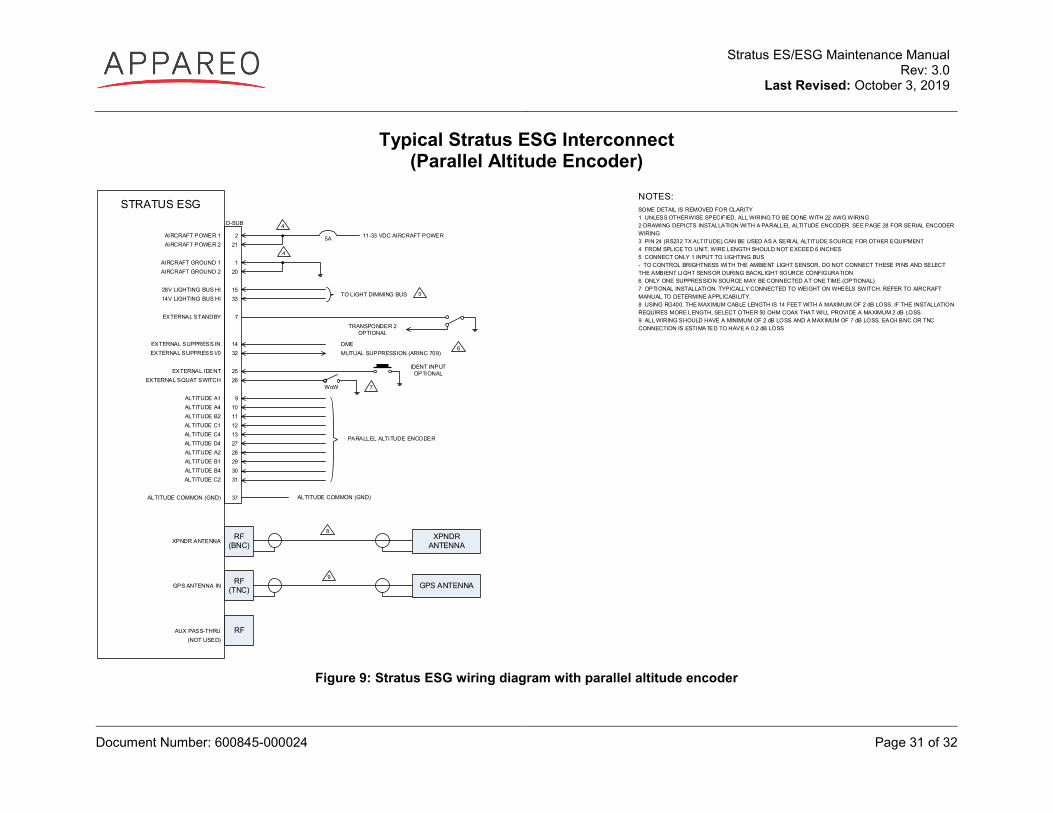
Typical Stratus ESG Interconnect (Parallel Altitude Encoder)
NOTES:SOME DETAIL IS REMOVED FOR CLARITY1 UNLESS OTHERWISE SPECIFIED, ALL WIRING TO BE DONE WITH 22 AWG WIRING2 DRAWING DEPICTS INSTALLATION WITH A PARALLEL ALTITUDE ENCODER. SEE PAGE 28 FOR SERIAL ENCODER WIRING3 PIN 24 (RS232 TX ALTITUDE) CAN BE USED AS A SERIAL ALTITUDE SOURCE FOR OTHER EQUIPMENT 4 FROM SPLICE TO UNIT, WIRE LENGTH SHOULD NOT EXCEED 6 INCHES5 CONNECT ONLY 1 INPUT TO LIGHTING BUS - TO CONTROL BRIGHTNESS WITH THE AMBIENT LIGHT SENSOR, DO NOT CONNECT THESE PINS AND SELECT THE AMBIENT LIGHT SENSOR DURING BACKLIGHT SOURCE CONFIGURATION6 ONLY ONE SUPPRESSION SOURCE MAY BE CONNECTED AT ONE TIME (OPTIONAL)7 OPTIONAL INSTALLATION. TYPICALLY CONNECTED TO WEIGHT ON WHEELS SWITCH. REFER TO AIRCRAFT MANUAL TO DETERMINE APPLICABILITY. 8 USING RG400, THE MAXIMUM CABLE LENGTH IS 14 FEET WITH A MAXIMUM OF 2 dB LOSS. IF THE INSTALLATION REQUIRES MORE LENGTH, SELECT OTHER 50 OHM COAX THAT WILL PROVIDE A MAXIMUM 2 dB LOSS. 9 ALL WIRING SHOULD HAVE A MINIMUM OF 2 dB LOSS AND A MAXIMUM OF 7 dB LOSS. EACH BNC OR TNC CONNECTION IS ESTIMATED TO HAVE A 0.2 dB LOSS
STRATUS ESG
AIRCRAFT POWER 1AIRCRAFT POWER 2
AIRCRAFT GROUND 1AIRCRAFT GROUND 2
28V LIGHTING BUS HI14V LIGHTING BUS HI
EXTERNAL STANDBY
EXTERNAL SUPPRESS INEXTERNAL SUPPRESS I/0
EXTERNAL IDENTEXTERNAL SQUAT SWITCH
ALTITUDE A1ALTITUDE A4ALTITUDE B2ALTITUDE C1ALTITUDE C4ALTITUDE D4ALTITUDE A2ALTITUDE B1ALTITUDE B4ALTITUDE C2
ALTITUDE COMMON (GND)
XPNDR ANTENNA
GPS ANTENNA IN
AUX PASS-THRU(NOT USED)
221
120
1533
7
1432
2526
9101112132728293031
37
11-33 VDC AIRCRAFT POWER
D-SUB
5A
TO LIGHT DIMMING BUS
PARALLEL ALTITUDE ENCODER
MUTUAL SUPPRESSION (ARINC 709)DME
TRANSPONDER 2OPTIONAL
RF(BNC)
XPNDR ANTENNA
RF(TNC) GPS ANTENNA
6
ALTITUDE COMMON (GND)
RF
IDENT INPUTOPTIONAL
WoW
4
4
5
7
8
9
Figure 9: Stratus ESG wiring diagram with parallel altitude encoder
Stratus ES/ESG Maintenance Manual Rev: 3.0
Last Revised: October 3, 2019
Document Number: 600845-000024 Page 32 of 32
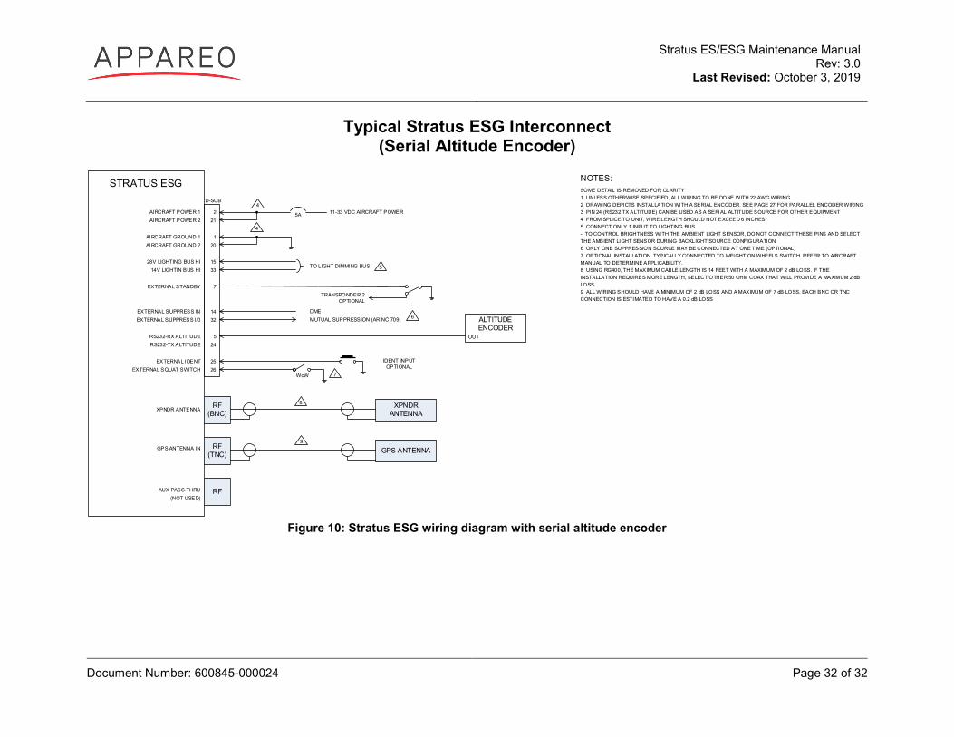
Typical Stratus ESG Interconnect (Serial Altitude Encoder)
STRATUS ESG
AIRCRAFT POWER 1AIRCRAFT POWER 2
AIRCRAFT GROUND 1AIRCRAFT GROUND 2
28V LIGHTING BUS HI14V LIGHTIN BUS HI
EXTERNAL STANDBY
EXTERNAL SUPPRESS INEXTERNAL SUPPRESS I/0
RS232-RX ALTITUDERS232-TX ALTITUDE
EXTERNAL IDENTEXTERNAL SQUAT SWITCH
XPNDR ANTENNA
GPS ANTENNA IN
AUX PASS-THRU(NOT USED)
221
120
1533
7
1432
524
2526
11-33 VDC AIRCRAFT POWER
D-SUB
5A
MUTUAL SUPPRESSION (ARINC 709)DME
TRANSPONDER 2OPTIONAL
XPNDR ANTENNA
GPS ANTENNA
ALTITUDE ENCODER
OUT
6
RF(BNC)
RF(TNC)
RF
TO LIGHT DIMMING BUS
7
IDENT INPUTOPTIONAL
WoW
NOTES:SOME DETAIL IS REMOVED FOR CLARITY1 UNLESS OTHERWISE SPECIFIED, ALL WIRING TO BE DONE WITH 22 AWG WIRING2 DRAWING DEPICTS INSTALLATION WITH A SERIAL ENCODER. SEE PAGE 27 FOR PARALLEL ENCODER WIRING3 PIN 24 (RS232 TX ALTITUDE) CAN BE USED AS A SERIAL ALTITUDE SOURCE FOR OTHER EQUIPMENT 4 FROM SPLICE TO UNIT, WIRE LENGTH SHOULD NOT EXCEED 6 INCHES5 CONNECT ONLY 1 INPUT TO LIGHTING BUS - TO CONTROL BRIGHTNESS WITH THE AMBIENT LIGHT SENSOR, DO NOT CONNECT THESE PINS AND SELECT THE AMBIENT LIGHT SENSOR DURING BACKLIGHT SOURCE CONFIGURATION6 ONLY ONE SUPPRESSION SOURCE MAY BE CONNECTED AT ONE TIME (OPTIONAL)7 OPTIONAL INSTALLATION. TYPICALLY CONNECTED TO WEIGHT ON WHEELS SWITCH. REFER TO AIRCRAFT MANUAL TO DETERMINE APPLICABILITY. 8 USING RG400, THE MAXIMUM CABLE LENGTH IS 14 FEET WITH A MAXIMUM OF 2 dB LOSS. IF THE INSTALLATION REQUIRES MORE LENGTH, SELECT OTHER 50 OHM COAX THAT WILL PROVIDE A MAXIMUM 2 dB LOSS. 9 ALL WIRING SHOULD HAVE A MINIMUM OF 2 dB LOSS AND A MAXIMUM OF 7 dB LOSS. EACH BNC OR TNC CONNECTION IS ESTIMATED TO HAVE A 0.2 dB LOSS
4
4
5
8
9
Figure 10: Stratus ESG wiring diagram with serial altitude encoder


![Stratus [stratus] The word stratus is a Latin word which means “flattened” or “spread out” or “layers” Stratus Clouds](https://img.pdfslide.us/doc/110x75/56649dc55503460f94ab81ce/stratus-stratus-the-word-stratus-is-a-latin-word-which-means-flattened.jpg)