Embed Size (px)
Citation preview

Revised 08-00$2.50
HDB 640 SCL 46
SCL 53SCL 35
Dry Disc Brake CalipersMaintenance Manual 4Y

Service Notes
Before You BeginThis manual provides installation and maintenanceprocedures for Meritor’s HDB 640, SCL 35, 46 and53 Series dry disc brake calipers. Before you beginprocedures:
1. Read and understand all instructions andprocedures before you begin to servicecomponents.
2. Read and observe all Caution and Warningsafety alerts that precede instructions orprocedures you will perform. These alerts helpto avoid damage to components, seriouspersonal injury, or both.
3. Follow your company’s maintenance andservice, installation, and diagnostics guidelines.
4. Use special tools when required to help avoidserious personal injury and damage tocomponents.
Safety Alerts, Torque Symbol and Notes
Access Information onArvinMeritor’s Web SiteAdditional maintenance and service informationfor ArvinMeritor’s commercial vehicle systemscomponent lineup is also available onArvinMeritor’s web site at www.arvinmeritor.com.
To access information, click on Products &Services/Tech Library Icon/HVS Publications. The screen will display an index of publicationsby type.
Additional InformationFor complete maintenance and serviceprocedures for all disc brake calipers, callArvinMeritor’s Customer Service Center at 800-535-5560 to order the following publications.
• Hydraulic Dry Disc Brake Parts (Parts Book PB-9201)
• Off-Highway Dry Disc Brakes (Publication SP-8611)
• Technical Electronic Library on CD. Featuresproduct and service information on mostArvinMeritor, ZF Meritor and Meritor WABCOcomponents. $20. Order TP-9853.WARNING A Warning alerts you to an
instruction or procedurethat you must followexactly to avoid seriouspersonal injury anddamage to components.
CAUTION A Caution alerts you to aninstruction or procedurethat you must followexactly to avoid damageto components andpossible serious personalinjury can also occur.
The torque symbol alertsyou to tighten fasteners toa specified torque value.
NOTE: A Note providesinformation orsuggestions that help youcorrectly service acomponent.
!
!
T

Table of Contents
Asbestos and Non-Asbestos Fibers Warnings.................................................................................i
Exploded Views ...............................................................................................................................................1HDB 640SCL 35 SeriesSCL 46 SeriesSCL 53 Series
Section 1: Introduction .................................................................................................................................5DescriptionHydraulic Fluid ..............................................................................................................................................6Identification
Section 2: Removal and Disassembly ....................................................................................................7Removal
Brake LiningsCaliper Housing
DisassemblyCaliper
Section 3: Inspection ...................................................................................................................................10Inspect Parts
Section 4: Prepare Parts for Assembly ................................................................................................12Clean, Dry and Protect Parts
Section 5: Assembly and Installation ...................................................................................................13AssemblyInstallationRemove Air from the System (“Bleed” the Brakes) ................................................................................15
Section 6: Troubleshooting.......................................................................................................................16Brake Does Not ApplyBrake Does Not Release
Section 7: Specifications............................................................................................................................17Torque ChartWear DimensionsHydraulic Fluid
!

i
NON-ASBESTOS FIBERS WARNINGThe following procedures for servicing brakes are recommended to reduceexposure to non-asbestos fiber dust, a potential cancer and lung diseasehazard. Material Safety Data Sheets are available from Meritor.
Hazard SummaryMost recently manufactured brake linings do not contain asbestos fibers. These brake liningsmay contain one or more of a variety of ingredients, including glass fibers, mineral wool, aramidfibers, ceramic fibers and silica that can present health risks if inhaled. Scientists disagree onthe extent of the risks from exposure to these substances. Nonetheless, exposure to silica dustcan cause silicosis, a non-cancerous lung disease. Silicosis gradually reduces lung capacityand efficiency and can result in serious breathing difficulty. Some scientists believe other typesof non-asbestos fibers, when inhaled, can cause similar diseases of the lung. In addition, silicadust and ceramic fiber dust are known to the State of California to cause lung cancer. U.S. andinternational agencies have also determined that dust from mineral wool, ceramic fibers andsilica are potential causes of cancer.
Accordingly, workers must use caution to avoid creating and breathing dust when servicingbrakes. Specific recommended work practices for reducing exposure to non-asbestos dustfollow. Consult your employer for more details.
Recommended Work Practices1. Separate Work Areas. Whenever feasible, service brakes in a separate area away fromother operations to reduce risks to unprotected persons.
2. Respiratory Protection. OSHA has set a maximum allowable level of exposure for silica of0.1 mg/m3 as an 8-hour time-weighted average. Some manufacturers of non-asbestos brakelinings recommend that exposures to other ingredients found in non-asbestos brake linings bekept below 1.0 f/cc as an 8-hour time-weighted average. Scientists disagree, however, to whatextent adherence to these maximum allowable exposure levels will eliminate the risk of diseasethat can result from inhaling non-asbestos dust.
Therefore, wear respiratory protection at all times during brake servicing, beginning with theremoval of the wheels. Wear a respirator equipped with a high-efficiency (HEPA) filterapproved by NIOSH or MSHA, if the exposures levels may exceed OSHA or manufacturer’srecommended maximum levels. Even when exposures are expected to be within the maximumallowable levels, wearing such a respirator at all times during brake servicing will help minimizeexposure.
3. Procedures for Servicing Brakes.
a. Enclose the brake assembly within a negative pressure enclosure. The enclosure should beequipped with a HEPA vacuum and worker arm sleeves. With the enclosure in place, usethe HEPA vacuum to loosen and vacuum residue from the brake parts.
b. As an alternative procedure, use a catch basin with water and a biodegradable, non-phosphate, water-based detergent to wash the brake drum or rotor and other brake parts.The solution should be applied with low pressure to prevent dust from becoming airborne.Allow the solution to flow between the brake drum and the brake support or the brake rotorand caliper. The wheel hub and brake assembly components should be thoroughly wetted tosuppress dust before the brake shoes or brake pads are removed. Wipe the brake parts cleanwith a cloth.
c. If an enclosed vacuum system or brake washing equipment is not available, carefully cleanthe brake parts in the open air. Wet the parts with a solution applied with a pump-spray bottlethat creates a fine mist. Use a solution containing water, and, if available, a biodegradable,non-phosphate, water-based detergent. The wheel hub and brake assembly componentsshould be thoroughly wetted to suppress dust before the brake shoes or brake pads areremoved. Wipe the brake parts clean with a cloth.
d. Wear a respirator equipped with a HEPA filter approved by NIOSH or MSHA when grindingor machining brake linings. In addition, do such work in an area with a local exhaustventilation system equipped with a HEPA filter.
e. NEVER use compressed air by itself, dry brushing, or a vacuum not equipped with a HEPAfilter when cleaning brake parts or assemblies. NEVER use carcinogenic solvents, flammablesolvents, or solvents that can damage brake components as wetting agents.
4. Cleaning Work Areas. Clean work areas with a vacuum equipped with a HEPA filter or bywet wiping. NEVER use compressed air or dry sweeping to clean work areas. When you emptyvacuum cleaners and handle used rags, wear a respirator equipped with a HEPA filterapproved by NIOSH or MSHA, to minimize exposure. When you replace a HEPA filter, wet thefilter with a fine mist of water and dispose of the used filter with care.
5. Worker Clean-Up. After servicing brakes, wash your hands before you eat, drink or smoke.Shower after work. Do not wear work clothes home. Use a vacuum equipped with a HEPA filterto vacuum work clothes after they are worn. Launder them separately. Do not shake or usecompressed air to remove dust from work clothes.
6. Waste Disposal. Dispose of discarded linings, used rags, cloths and HEPA filters with care,such as in sealed plastic bags. Consult applicable EPA, state and local regulations on wastedisposal.
Regulatory GuidanceReferences to OSHA, NIOSH, MSHA, and EPA, which are regulatory agencies in the UnitedStates, are made to provide further guidance to employers and workers employed within theUnited States. Employers and workers employed outside of the United States should consult theregulations that apply to them for further guidance.
!ASBESTOS FIBER WARNINGThe following procedures for servicing brakes are recommended to reduceexposure to asbestos fiber dust, a cancer and lung disease hazard. MaterialSafety Data Sheets are available from Meritor.
Hazard SummaryBecause some brake linings contain asbestos, workers who service brakes must understand thepotential hazards of asbestos and precautions for reducing risks. Exposure to airborne asbestosdust can cause serious and possibly fatal diseases, including asbestosis (a chronic lung disease)and cancer, principally lung cancer and mesothelioma (a cancer of the lining of the chest orabdominal cavities). Some studies show that the risk of lung cancer among persons who smokeand who are exposed to asbestos is much greater than the risk for non-smokers. Symptoms ofthese diseases may not become apparent for 15, 20 or more years after the first exposure toasbestos.
Accordingly, workers must use caution to avoid creating and breathing dust when servicingbrakes. Specific recommended work practices for reducing exposure to asbestos dust follow.Consult your employer for more details.
Recommended Work Practices1. Separate Work Areas. Whenever feasible, service brakes in a separate area away from otheroperations to reduce risks to unprotected persons. OSHA has set a maximum allowable level ofexposure for asbestos of 0.1 f/cc as an 8-hour time-weighted average and 1.0 f/cc averaged over a30-minute period. Scientists disagree, however, to what extent adherence to the maximumallowable exposure levels will eliminate the risk of disease that can result from inhaling asbestosdust. OSHA requires that the following sign be posted at the entrance to areas where exposuresexceed either of the maximum allowable levels:
DANGER: ASBESTOS CANCER AND LUNG DISEASE HAZARD
AUTHORIZED PERSONNEL ONLY RESPIRATORS AND PROTECTIVE CLOTHING
ARE REQUIRED IN THIS AREA
2. Respiratory Protection. Wear a respirator equipped with a high-efficiency (HEPA) filterapproved by NIOSH or MSHA for use with asbestos at all times when servicing brakes, beginningwith the removal of the wheels.
3. Procedures for Servicing Brakes.
a. Enclose the brake assembly within a negative pressure enclosure. The enclosure should beequipped with a HEPA vacuum and worker arm sleeves. With the enclosure in place, use theHEPA vacuum to loosen and vacuum residue from the brake parts.
b. As an alternative procedure, use a catch basin with water and a biodegradable, non-phosphate, water-based detergent to wash the brake drum or rotor and other brake parts. Thesolution should be applied with low pressure to prevent dust from becoming airborne. Allowthe solution to flow between the brake drum and the brake support or the brake rotor andcaliper. The wheel hub and brake assembly components should be thoroughly wetted tosuppress dust before the brake shoes or brake pads are removed. Wipe the brake parts cleanwith a cloth.
c. If an enclosed vacuum system or brake washing equipment is not available, employers mayadopt their own written procedures for servicing brakes, provided that the exposure levelsassociated with the employer’s procedures do not exceed the levels associated with theenclosed vacuum system or brake washing equipment. Consult OSHA regulations for moredetails.
d. Wear a respirator equipped with a HEPA filter approved by NIOSH or MSHA for use withasbestos when grinding or machining brake linings. In addition, do such work in an area witha local exhaust ventilation system equipped with a HEPA filter.
e. NEVER use compressed air by itself, dry brushing, or a vacuum not equipped with a HEPAfilter when cleaning brake parts or assemblies. NEVER use carcinogenic solvents, flammablesolvents, or solvents that can damage brake components as wetting agents.
4. Cleaning Work Areas. Clean work areas with a vacuum equipped with a HEPA filter or by wetwiping. NEVER use compressed air or dry sweeping to clean work areas. When you emptyvacuum cleaners and handle used rags, wear a respirator equipped with a HEPA filter approvedby NIOSH or MSHA for use with asbestos. When you replace a HEPA filter, wet the filter with afine mist of water and dispose of the used filter with care.
5. Worker Clean-Up. After servicing brakes, wash your hands before you eat, drink or smoke.Shower after work. Do not wear work clothes home. Use a vacuum equipped with a HEPA filter tovacuum work clothes after they are worn. Launder them separately. Do not shake or usecompressed air to remove dust from work clothes.
6. Waste Disposal. Dispose of discarded linings, used rags, cloths and HEPA filters with care,such as in sealed plastic bags. Consult applicable EPA, state and local regulations on wastedisposal.
Regulatory GuidanceReferences to OSHA, NIOSH, MSHA, and EPA, which are regulatory agencies in the UnitedStates, are made to provide further guidance to employers and workers employed within theUnited States. Employers and workers employed outside of the United States should consult theregulations that apply to them for further guidance.
!
Asbestos and Non-Asbestos Fibers
1
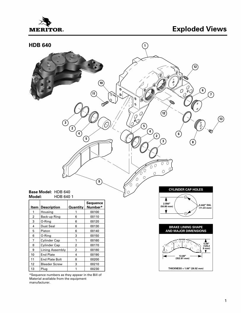
HDB 640
Base Model: HDB 640Model: HDB 640 1
SequenceItem Description Quantity Number*
1 Housing 1 001002 Back-up Ring 6 001103 O-Ring 6 001204 Dust Seal 6 001305 Piston 6 001406 O-Ring 3 001507 Cylinder Cap 1 001608 Cylinder Cap 2 001709 Lining Assembly 2 00180
10 End Plate 4 0019011 End Plate Bolt 8 0020012 Bleeder Screw 3 0021013 Plug 1 00230
*Sequence numbers as they appear in the Bill ofMaterial available from the equipmentmanufacturer.
10
11
3
2
4
5
9
5
42
3
12
6
8
13
76
12
1
THICKNESS = 1.06" (26.92 mm)
13.89"(352.81 mm)
5.09"(129.29 mm)
BRAKE LINING SHAPEAND MAJOR DIMENSIONS
CYLINDER CAP HOLES
Exploded Views
0.442" DIA.(11.23 mm)
2.000"(50.80 mm)

2
SCL 35 Series
Base Model: SCL 35Models: SCL 35 1
SCL 35 5Sequence
Item Description Quantity Number*1 Housing 1 001002 Back-up Ring 6 001103 O-Ring 6 001204 Dust Seal 6 001305 Piston 6 001406 O-Ring 3 001507 Cylinder Cap 1 001608 Cylinder Cap 2 001709 Lining Assembly 2 00180
10 End Plate 4 0019011 End Plate Bolt 8 0020012 Bleeder Screw 2 0021013 Plug 1 00220
*Sequence numbers as they appear in the Bill ofMaterial available from the equipmentmanufacturer.
THICKNESS = 1.06" (26.92 mm)
15.536"(394.61 mm)
5.18"(131.57
mm)
BRAKE LINING SHAPEAND MAJOR DIMENSIONS
Exploded Views

3
SCL 46 Series
Base Model: SCL 46Model: SCL 46
SequenceItem Description Quantity Number*
1 Housing 1 001002 Back-up Ring 6 001103 O-Ring 6 001204 Dust Seal 6 001305 Piston 6 001406 O-Ring 3 001507 Cylinder Cap 1 001608 Cylinder Cap 2 001709 Lining Assembly 2 00180
10 End Plate 4 0019011 End Plate Bolt 8 0020012 Bleeder Screw 2 0021013 Plug 1 00220
*Sequence numbers as they appear in the Bill ofMaterial available from the equipmentmanufacturer.
THICKNESS = 1.06" (26.92 mm)
13.89"(352.81 mm)
5.09"(129.29 mm)
BRAKE LINING SHAPEAND MAJOR DIMENSIONS
Exploded Views

4
SCL 53 Series
Base Model: SCL 53Models: SCL 53
SCL 53 1, SCL 53 2
SequenceItem Description Quantity Number*
1 Housing 1 001002 Back-up Ring 6 001103 O-Ring 6 001204 Dust Seal 6 001305 Piston 6 001406 O-Ring 3 001507 Cylinder Cap 1 001608 Cylinder Cap 2 001709 Lining Assembly 2 00180
10 End Plate 4 0019011 End Plate Bolt 8 0020012 Plug 1 0021013 Bleeder Screw 3 00220
*Sequence numbers as they appear in the Bill ofMaterial available from the equipmentmanufacturer. THICKNESS = 1.06" (26.92 mm)
15.536"(394.61 mm)
5.18"(131.57
mm)
BRAKE LINING SHAPEAND MAJOR DIMENSIONS
Exploded Views

5
DescriptionThe HDB 640, SCL 35, 46 and 53 Series dry discbrake calipers are intended only for service use onhydraulic brake systems. All calipers mount to afixed position on fixed position discs. Figures 1.1,1.2, 1.3 and 1.4.
One or two calipers can be used on a disc. Installthe SCL 35 and SCL 46 calipers at the 3 or 9o’clock positions. Install the HDB 640 and SCL 53calipers at the 3, 9, or 12 o’clock positions.
The calipers are designed to be used on thefollowing size discs:
SCL 35
SCL 46
SCL 53
Figure 1.2
HDB 640
Figure 1.1
Figure 1.3
Figure 1.4
Model Disc Size/Inches (millimeters)
HDB 640 18.50" (470 mm) in a 25" rim (635 mm)
SCL 35 22.50" (571 mm) in a 29" rim (737 mm)
SCL 46 18.75" (476 mm) in a 25" rim (635 mm)
SCL 53 26" (660 mm) in a 33" rim (838 mm)28" (711 mm) ina 35" rim (889 mm)
Section 1Introduction

6
Identification
An assembly number located on the side of thecaliper that is opposite from the mounting plateidentifies older assemblies. An identification taglocated on the inside radius of the caliperidentifies more recent assemblies. Figure 1.5.
Figure 1.5
BRAKE SPECIFICATION NUMBER:__________MANUFACTURING PLANT:_________________
ID TAG (RECENTASSEMBLIES):
Hydraulic Fluid
WARNINGUse only the type of hydraulic fluid specified bythe equipment manufacturer. Do not use or mixdifferent types of hydraulic fluid. Using incorrecthydraulic fluid will damage the rubber parts ofthe caliper. Loss of braking control, seriouspersonal injury and damage to components can result.
Do not reuse hydraulic fluid. Used fluid can becontaminated and can cause incorrect operation.Serious personal injury and damage tocomponents can result.
The HDB 640, SCL 35, 46, and 53 brake systemsuse one of two types of hydraulic fluid:
!
Section 1Introduction
Petroleum Base Non-Petroleum Base Hydraulic Fluid Hydraulic Fluid (Mineral Oil) (Automotive Brake Fluid)
Example: Example:Meets MIL-H-5606 Glycol DOT 3, meets SAE specifications J-1703 specifications

7
Section 2Removal and Disassembly
WARNINGTo prevent serious eye injury, always wear safeeye protection when you perform vehiclemaintenance or service.
Removal
WARNINGPark the vehicle on a level surface. Block thewheels to prevent the vehicle from moving.Support the vehicle with safety stands. Do notwork under a vehicle supported only by jacks.Jacks can slip and fall over. Serious personalinjury can result.
1. Park the vehicle on a level surface.
2. Place blocks under the wheels not beingserviced to keep the vehicle from moving.
3. If necessary, raise the vehicle so that thewheels to be serviced are off the ground.Support the vehicle with safety stands.
4. Remove the wheel.
Brake Linings
1. Remove the bolts that fasten the end plates toone side of the caliper housing. Remove the endplates. Replace worn or damaged end plates.
2. Loosen the bleeder screws in the caliperhousings to release hydraulic pressure.
3. Use a piece of wood to pry the linings awayfrom the disc and push the pistons completelyinto the housing. Tighten the bleeder screws.
4. Remove the linings from the housing. Inspectthe linings. Refer to “Linings and End Plates” inSection 3.
• If you are only changing the linings: Refer to“Linings” in Section 5.
!
! Caliper Housing
WARNINGHousings are very heavy. Support the housingduring removal and installation. Serious personalinjury or damage to caliper can occur if a caliperhousing falls.
NOTE: To lighten caliper weight, remove thebrake linings from the caliper before you removethe caliper from the vehicle.
1. Disconnect the brake line from the inlet fitting.Put a plug in the brake line and the inlet fittingto prevent contamination of the system.
2. Remove the linings as described earlier in thissection.
3. Remove the fasteners that hold the caliperhousing onto the mounting bracket. Removethe caliper housing from the mounting bracket.
• If shims are used between the housing andmounting bracket: Mark the shim positions.
DisassemblyCaliper
1. Remove the inlet fitting and the O-ring fromthe cylinder cap. Drain the hydraulic fluid fromthe caliper. Discard the fluid.
2. Clean the outside of the housing with isopropylalcohol. Dry the housing with a clean cloth.
3. If installed, remove the bolts that hold the endplates on the housing. Remove the end platesand linings.
!

8
Section 2Removal and Disassembly
4. Remove the pistons from the side of thehousing opposite the mounting plateaccording to the following procedure:
A. Use a C-clamp to hold a 0.50 inch (12.7mm) block of wood against three pistonson the mounting side of the housing. Makesure the C-clamp is not in the area in frontof the piston bore. Figure 2.1.
WARNINGDo not put your hand in front of the pistons whenyou force the pistons out of the housing. Seriouspersonal injury can occur.
B. Apply compressed air to the inlet fitting toforce the pistons out of the housing. If onepiston comes out before the other piston,put a piece of wood in front of the pistonthat comes out first.
C. Apply compressed air to force the otherpiston out of the housing.
D. Remove the wood block and the C-clampfrom the housing.
E. Remove the pistons from the bores that areopposite from the mounting plate.
5. Remove the two bleeder screws from thehousing.
6. Use the following procedures to remove thecylinder caps from the housing. Figure 2.2.
!
7. Remove the pistons from the mounting plateside of the housing. Push on the cap ends ofthe pistons to force them out of the disc side ofthe housing.
8. Remove the dust seals from the housing.
NOTE: Use a soft tool to prevent scratching thehousing and grooves.
9. Use a soft tool to remove the O-rings andbackup rings. Discard the parts. Figure 2.3.
10. Inspect the ring grooves in the housing forscratches and rust. Use a fine emery cloth toremove small scratches and rust.
• If scratches are deep, or there is a largeamount of rust: Replace the housing. Refer to“Caliper” in Section 3.
Figure 2.3
O-RING
BACK-UP RING
0.442" DIA.(11.23 mm)
2.000"(50.80 mm)
Figure 2.2HDB 640 Cylinder Cap Holes
C-CLAMP
PISTON
AIR GUN WOODBLOCK
Figure 2.1

9
Section 2Removal and Disassembly
11. Inspect the pistons and bores for scratchesand rust. Use a fine emery cloth to removesmall scratches and rust.
• If scratches are deep, there is a large amountof rust, or the pistons and bores are damaged:Replace the components. Refer to “Caliper” inSection 3.
10
Section 3Inspection
WARNINGTo prevent serious eye injury, always wear safeeye protection when you perform vehiclemaintenance or service.
Inspect PartsLinings and End Plates
CAUTIONAlways replace both linings with specified parts.If you only replace one lining, damage to the disccan occur. If you use non-Meritor parts, incorrectbrake operation can occur. Damage tocomponents can result.
1. Remove the linings. Inspect the linings for wearand damage. Replace damaged linings.
2. Replace the linings if you find the followingconditions:
• The thickness is 0.125-inch (3.2 mm) fromthe backplate.
• Each lining has a different thickness.
• The linings are contaminated with oil orgrease.
• The linings have large or deep cracks. Small,tight cracks (heat checks) on the lining’ssurface, which are caused by hightemperatures, are normal.
3. Inspect the end plate and end plate bolts forwear. Replace worn or damaged end plates andbolts.
Dust Seals
Check that the dust seals are soft and flexible.Replace worn or damaged seals.
!
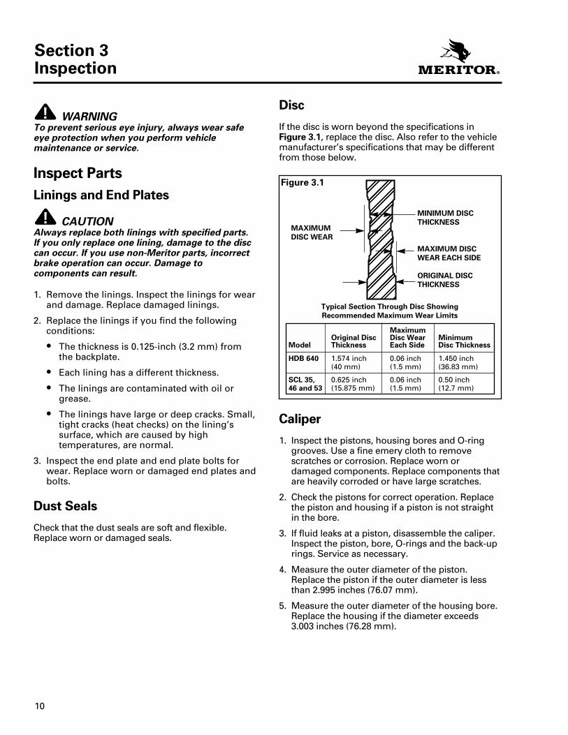
! Disc
If the disc is worn beyond the specifications inFigure 3.1, replace the disc. Also refer to the vehiclemanufacturer’s specifications that may be differentfrom those below.
Caliper
1. Inspect the pistons, housing bores and O-ringgrooves. Use a fine emery cloth to removescratches or corrosion. Replace worn ordamaged components. Replace components thatare heavily corroded or have large scratches.
2. Check the pistons for correct operation. Replacethe piston and housing if a piston is not straightin the bore.
3. If fluid leaks at a piston, disassemble the caliper.Inspect the piston, bore, O-rings and the back-uprings. Service as necessary.
4. Measure the outer diameter of the piston.Replace the piston if the outer diameter is lessthan 2.995 inches (76.07 mm).
5. Measure the outer diameter of the housing bore.Replace the housing if the diameter exceeds3.003 inches (76.28 mm).
����������������������������������������Figure 3.1
Maximum Original Disc Disc Wear Minimum
Model Thickness Each Side Disc Thickness
HDB 640 1.574 inch 0.06 inch 1.450 inch(40 mm) (1.5 mm) (36.83 mm)
SCL 35, 0.625 inch 0.06 inch 0.50 inch46 and 53 (15.875 mm) (1.5 mm) (12.7 mm)
MINIMUM DISCTHICKNESS
MAXIMUM DISCWEAR EACH SIDE
ORIGINAL DISCTHICKNESS
MAXIMUMDISC WEAR
Typical Section Through Disc ShowingRecommended Maximum Wear Limits

11
Section 3Inspection
6. Inspect inlet fitting and O-ring for damage.Replace O-ring if necessary.
7. Inspect the linings as described earlier in thissection.
8. Inspect caliper ports and end plate bolt holesfor thread damage. Refer to the table below.
A. Use the appropriate taps lubricated withlight oil to inspect tapped holes for threaddamage and to clean minor thread damage.
B. Replace components with thread damagethat you cannot repair. Use a thread tap torepair minor damage.
9. Discard all back-up rings, O-rings and dustboots. Install new ones when you assemble thecaliper.
Area to Inspect Tap Size to Use
Bleeder ports 0.4375-20 UNF
End plate bolt holes 0.6250-11 UNC
Inlet port 0.5000-20 UNF

12
Section 4Prepare Parts for Assembly
WARNINGTo prevent serious eye injury, always wear safeeye protection when you perform vehiclemaintenance or service.
Clean, Dry and Protect Parts
WARNINGSolvent cleaners can be flammable, poisonousand cause burns. Examples of solvent cleaners arecarbon tetrachloride, emulsion-type cleaners andpetroleum-based cleaners. To avoid seriouspersonal injury when you use solvent cleaners,you must carefully follow the manufacturer’sproduct instructions and these procedures:
• Wear safe eye protection.
• Wear clothing that protects your skin.
• Work in a well-ventilated area.
• Do not use gasoline, or solvents that containgasoline. Gasoline can explode.
• You must use hot solution tanks or alkalinesolutions correctly. Follow the manufacturer’sinstructions carefully.
Cleaning Parts
CAUTIONDo not use hot solution tanks or water andalkaline solutions to clean ground or polishedparts. Damage to parts will result.
1. Use a cleaning solvent or kerosene or dieselfuel to clean ground or polished metal parts or surfaces. Examples of ground or polishedparts are the piston and the piston bore in the caliper.
2. Use a cleaning solvent or a weak alkalinesolution in a hot solution tank to clean roughmetal parts. If you use a hot solution tank,follow the instructions below.
A. Leave the parts in the tank until they arecompletely cleaned and heated.
B. Remove the parts from the tank.
C. Wash the parts with water until you removethe alkaline solution.
!
!
!3. Use a wire brush to clean fastener and fitting
threads.
4. Remove mud and dirt on the linings. Replaceall linings contaminated with oil or grease.
Dry Parts Immediately After Cleaning
1. Use soft, clean paper or cloth rags, orcompressed air to completely dry partsimmediately after you clean them.
2. Carefully inspect all parts for wear or damagebefore you assemble them.
3. Repair or replace worn or damaged parts.
Apply Corrosion Protection
1. Apply a thin layer of grease to cleaned, driedparts. Be careful that you do not apply thegrease to the linings or rotor.
2. If you will store the parts, apply a specialmaterial, which prevents corrosion and rust, toall surfaces. Store parts inside special paper orother material that prevents rust and corrosion.

13
Section 5Assembly and Installation
3. Install a new dust seal into the top groove ofthe bore. Do not use silicone grease on the dustseal. Figure 5.1.
NOTE: Take care when you install the O-ring, sothat the cylinder cap threads don’t cut the O-ring.
4. Install a new O-ring into the cylinder capgroove between the threads and flange.
NOTE: Apply extra grease to the O-ring beforeyou install a cylinder cap to help prevent the O-ring from catching on cylinder cap threads.
5. Apply extra grease to the O-ring. Install thecylinder cap into the caliper housing. Tightenthe cylinder cap to the following specificaitons.
6. Install the pistons into the housing, with thehole in the piston toward the lining. Push thepistons into the housing from the lining side ofthe housing. Check that the pistons are straightin the bores.
7. Push each piston into the bore until the top ofeach piston is even with the top of the dustseal.
8. Install the bleeder screws into the housing andtighten them to 100-180 lb-in (11.3-20.3 N•m).
9. Install the O-ring and the inlet fitting into thecylinder cap.
InstallationCaliper
1. Place blocks under the wheels of the vehicle tokeep the vehicle from moving.
2. If shims are used, put the shims in the positionmarked during removal.
3. Place the caliper housing on the mountingbracket. Install the fasteners that hold thecaliper onto the bracket. Tighten the fastenersto the torque specified by the equipmentmanufacturer.
WARNINGTo prevent serious eye injury, always wear safeeye protection when you perform vehiclemaintenance or service.
AssemblyCaliper
CAUTIONOnly use specified components when youassemble the caliper. If you install the incorrectcomponents, the caliper will not operatecorrectly. If you use non-Meritor parts, incorrectbrake operation can occur. Damage tocomponents can result.
NOTE: You must lubricate the O-rings, back-uprings, pistons and bores before you can install the pistons.
1. Lubricate all pistons, bores, O-rings and back-up rings with silicone grease such as DowCorning DC-4 or equivalent. If silicone grease isnot available, use the same type of fluid that isused in the brake system.
2. Install a new O-ring and a back-up ring into thegroove in the middle of the bore.
A. Install the back-up ring toward the liningside of the bore. Figure 5.1.
B. Install the O-ring behind the back-up ring.Figure 5.1.
!
!
T
Figure 5.1
Install the back-upring toward lining
side of bore.
Install the O-ring behindthe back-up ring.
O-RING
BACK-UP RING
DUST SEAL
BACK-UP RINGAND O-RINGGROOVE
DUST SEALGROOVE
Model Torque (Minimum)
HDB 640 500 lb-ft (680 N•m)
SCL 35, SCL 46, SCL 53 75 lb-ft (100 N•m)

14
Section 5Assembly and Installation
Linings
CAUTIONReplace the linings on both brakes of a singleaxle at the same time. Use Meritor parts. The useof non-Meritor parts can damage the discs andaffect brake operation.
1. Place blocks under the wheels of the vehicle tokeep the vehicle from moving.
2. Install the linings in the caliper housing withthe metal backing plate against the pistons andnot toward disc.
WARNINGTake care when you use Loctite® to avoid seriouspersonal injury. Follow the manufacturer’sinstructions to prevent irritation to the eyes and skin.
3. Apply Loctite® 271 or equivalent to the threadsof the bolts and fasten the end plates to thehousing.
4. Install the end plates onto the housing. Installthe bolts and tighten them to 165-210 lb-ft(224-285 N•m). Ensure that the linings movefreely in the housing.
5. Remove the air from the brake system. Refer to“Remove Air From the System,” below.
6. Apply and release the brakes three times toensure the caliper operates correctly. Check forfluid leaks. Ensure that the linings move freelyin the housing.
!
!WARNING
Take care when you use Loctite® to avoid serious personal injury. Follow the manufacturer’sinstructions to prevent irritation to the eyes and skin.
4. Install the brake linings into the caliperhousing, with the metal backing plate againstthe pistons and not toward disc. Apply Loctite®
271 or equivalent to the threads of the boltsthat fasten the end plates to the housing.
5. Install the end plates onto the housing. Installthe bolts and tighten them to 165-210 lb-ft (224-285 N•m).
6. Check that the housing is installed correctly onthe mounting bracket. The disc must be within + 0.06 inches (+ 1.5 mm) of being centeredbetween the lining end plates.
NOTE: Shims must be steel, and ground flat andparallel.
• If it is necessary to install a shim: Install theshim either between the housing and mountingbracket, or between the hub and disc, toincrease outboard clearance and decreaseinboard clearance.
A shim must cover the entire hub or housingmounting surface, and the linings must movefreely in the housing and between the endplates.
7. Remove the plugs from the brake line and theinlet fitting. Connect the brake line to the inletfitting.
8. Remove the air from the brake system. Refer to“Remove Air from the System.”
9. Apply and release the brakes three times toensure the caliper operates correctly. Check forfluid leaks. Check that the linings move freely inthe caliper.
!
T
T

15
Section 5Assembly and Installation
Remove Air from the System(“Bleed” the Brakes)
WARNINGYou must bleed the brakes to remove all air fromthe system, when you loosen any brake systemhydraulic connection. Air can prevent hydraulicpressure from applying the brakes properly andcan increase stopping distance. Serious personalinjury and damage to components can result.
Use only the type of hydraulic fluid specified bythe equipment manufacturer. Do not use or mixdifferent types of hydraulic fluid. Using incorrecthydraulic fluid will damage the rubber parts of thecaliper. Loss of braking control, serious personalinjury and damage to components can result.
Do not reuse hydraulic fluid. Used fluid can becontaminated and can cause incorrect operation.Serious personal injury and damage tocomponents can result.
1. Check that the master cylinder is filled to thecorrect level with hydraulic fluid specified bythe component manufacturer. Keep the mastercylinder filled when you bleed the brakes, so airdoes not enter the system through the mastercylinder.
2. When you have finished bleeding the brakes,check that the master cylinder is filled to thecorrect level.
3. Put a clear tube on the bleeder screw.Submerge the opposite end of the tube into aclear container of the specified hydraulic fluid.
• HDB 640 and SCL 53 dry disc brakes aredesigned to bleed correctly when mounted atthe three, nine and twelve o’clock positions.
• SCL 35 and SCL 46 dry disc brakes aredesigned to bleed correctly when mounted inthe three and nine o’clock positions.
4. Always start at the point in the system that isfarthest from the master cylinder and workback toward the master cylinder.
!
5. When you complete a bleeder screw: Go tothe next closest bleeder screw on the samecaliper.
6. When you complete a caliper: Go to the nextclosest caliper on the same wheel.
7. When you complete a wheel: Go to thefarthest bleeder screw on the next closestwheel.
8. Follow the instructions below to bleed thebrakes.
Full Hydraulic Systems1. Slowly apply low hydraulic pressure to the
caliper. Loosen the bleeder screw.
2. Continue to apply pressure until there are noair bubbles in the hydraulic fluid.
3. Tighten the bleeder screw to 100-180 lb-in(11.3-20.3 N•m). Release the pressure to thecaliper.
4. Check for fluid leaks.
Air Hydraulic or Mechanical Actuator Systems
1. Apply the brake pedal. Loosen the bleederscrew.
2. Tighten the bleeder screw 100-180 lb-in (11.3-20.3 N•m) before you release the brakepedal so that air does not enter the system.
3. Repeat until there are no air bubbles in thehydraulic fluid when you apply the brakepedal and loosen the bleeder screw.
4. Check for fluid leaks.
T
T
16
Section 6Troubleshooting
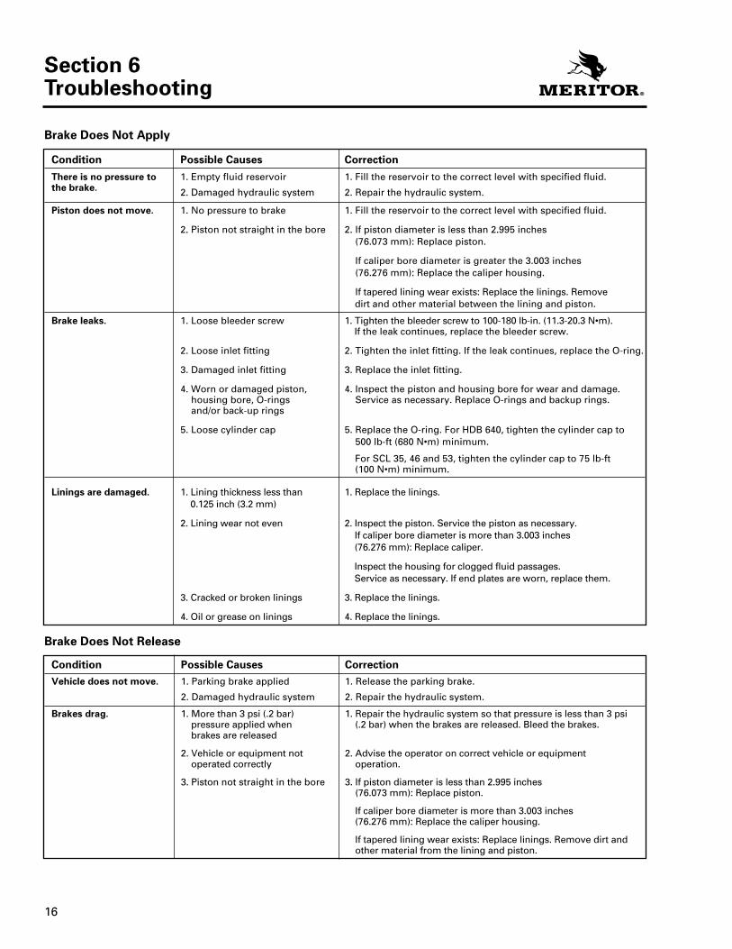
Brake Does Not Apply
Condition Possible Causes Correction
There is no pressure to 1. Empty fluid reservoir 1. Fill the reservoir to the correct level with specified fluid.the brake. 2. Damaged hydraulic system 2. Repair the hydraulic system.
Piston does not move. 1. No pressure to brake 1. Fill the reservoir to the correct level with specified fluid.
2. Piston not straight in the bore 2. If piston diameter is less than 2.995 inches (76.073 mm): Replace piston.
If caliper bore diameter is greater the 3.003 inches (76.276 mm): Replace the caliper housing.
If tapered lining wear exists: Replace the linings. Remove dirt and other material between the lining and piston.
Brake leaks. 1. Loose bleeder screw 1. Tighten the bleeder screw to 100-180 lb-in. (11.3-20.3 N•m).If the leak continues, replace the bleeder screw.
2. Loose inlet fitting 2. Tighten the inlet fitting. If the leak continues, replace the O-ring.
3. Damaged inlet fitting 3. Replace the inlet fitting.
4. Worn or damaged piston, 4. Inspect the piston and housing bore for wear and damage.housing bore, O-rings Service as necessary. Replace O-rings and backup rings.and/or back-up rings
5. Loose cylinder cap 5. Replace the O-ring. For HDB 640, tighten the cylinder cap to 500 lb-ft (680 N•m) minimum.
For SCL 35, 46 and 53, tighten the cylinder cap to 75 lb-ft (100 N•m) minimum.
Linings are damaged. 1. Lining thickness less than 1. Replace the linings.0.125 inch (3.2 mm)
2. Lining wear not even 2. Inspect the piston. Service the piston as necessary. If caliper bore diameter is more than 3.003 inches(76.276 mm): Replace caliper.
Inspect the housing for clogged fluid passages.Service as necessary. If end plates are worn, replace them.
3. Cracked or broken linings 3. Replace the linings.
4. Oil or grease on linings 4. Replace the linings.
Brake Does Not Release
Condition Possible Causes CorrectionVehicle does not move. 1. Parking brake applied 1. Release the parking brake.
2. Damaged hydraulic system 2. Repair the hydraulic system.
Brakes drag. 1. More than 3 psi (.2 bar) 1. Repair the hydraulic system so that pressure is less than 3 psi pressure applied when (.2 bar) when the brakes are released. Bleed the brakes.brakes are released
2. Vehicle or equipment not 2. Advise the operator on correct vehicle or equipment operated correctly operation.
3. Piston not straight in the bore 3. If piston diameter is less than 2.995 inches(76.073 mm): Replace piston.
If caliper bore diameter is more than 3.003 inches(76.276 mm): Replace the caliper housing.
If tapered lining wear exists: Replace linings. Remove dirt andother material from the lining and piston.

17
Section 7Specifications
Torque Chart
Wear Dimensions*
Hydraulic Fluid*
*See fluid and specification recommendations of equipmentmanufacturer.
Component Torque
End plate bolts 165-210 lb-ft (224-285 N•m)
Caliper mounting Vehicle manufacturer’sbracket fasteners specification
Bleeder screws 100-180 lb-in (11.3-20.3 N•m)
Cylinder capHDB 640 500 lb-ft (680 N•m) minimumSCL 35, 46 and 53 75 lb-ft (100 N•m) minimum
Component When to Replace
Disc Wear exceeds maximum of0.06 in (1.5 mm) per side
Housing Bore diameter exceeds3.003 in (76.276 mm)
Linings Thickness is less than 0.125 in(3.2 mm) from back plate
Piston Diameter worn to less than2.995 in (76.073 mm)
Component Example
Petroleum Base Hydraulic Meets MIL-H-5606Fluid (Mineral Oil) specifications
Non-Petroleum Base Glycol DOT 3, meetsHydraulic Fluid SAE J-1703 specifications(Automotive Brake Fluid)

Notes

Notes

Notes

Information contained in this publication was in effect at the time the publication was approved for printing and is subject to change without notice or liability. ArvinMeritor Commercial Vehicle Systems reserves the right to revise the information presented or discontinue the production of parts described at any time.
ArvinMeritor, Inc. Meritor do Brasil Ltda. Meritor Commercial Vehicle Systems Saint-Etienne S.A.Commercial Vehicle Systems Av. João Batista, 824 4, Rue Jean Servanton2135 West Maple Road 06097-900 Osasco-SP Boite Postale 656Troy, MI 48084 U.S.A. BRAZIL 42042 Saint Etienne Cedex 1 Maintenance Manual 4Y248-435-1085 (55-11) 7084-6510 FRANCE Revised 08-00800-535-5560 (North America only) Fax: (55-11) 7084-6600 (33) 477.92.88.00 Fax: (33) 477.92.88.93 47865/24240www.arvinmeritor.com
Copyright 2000 ArvinMeritor, Inc. All Rights Reserved Printed in the U.S.A.


![دانشگاه صنعتی اصفهانDownloaded from jcme.iut.ac.ir at 10:10 IRST on Wednesday February 3rd 2021 [ DOI: 10.18869/acadpub.jcme.36.1.47 ] .(@9A2 4Y/ ' @9A 4Y /m](https://img.pdfslide.us/doc/110x75/60e55696fce8766a480bea8d/-oe-downloaded-from-jcmeiutacir-at-1010-irst.jpg)