Embed Size (px)
Citation preview

MAINTENANCE INSTRUCTIONS
BLADDER ACCUMULATORS
Rev B
Tel: 714-529-9495 Fax: 714-529-1366 561 Tamarack Ave, Brea CA USA www.pacsealhydraulics.com
General
Hydraulic Accumulators are pressure vessels and maycontain compressed nitrogen gas or hydraulic fluid athigh pressures.
Only qualified personnel should perform
maintenance.
DO NOT weld on the accumulator shell.
Always use DRY NITROGEN for precharging.
Do not use automotive valve cores in place of highpressure valve cores.
For maximum seal and bladder life, hydraulic fluidshould be kept clean, filtered to 10 micron or less.
HYDRAULIC PRESSURE MUST BE
REDUCED TO ZERO.
VENT all precharge gas prior to disassembly.
NEVER USE AIR OR OXYGEN for precharge
as this may result in an explosion!
PRECHARGING PROCEDURE
ISOLATE, VENT and DRAIN all fluid completely fromaccumulator. Only check precharge when fluid
pressure is “0 psi”.
Remove valve guard (8) and valve cap (7) (Figure 1).
Use PacSeal charging and gauging assembly, partnumber 40-1618, to check and adjust precharge of theaccumulator.
Before using the assembly, verify that the bleed valve(E) is closed and the air chuck (A) is turned fullycounter-clockwise (CCW) (Figure 2).
Connect the air chuck (A) to the gas fill valve (4) on theaccumulator.
Connect the hose assembly to the nitrogen bottle, thenconnect it to the fill valve (D) on the charging unit.
Depress the valve core by turning the charging valveclockwise (CW) until it stops (do not over torque).SLOWLY open the valve on the nitrogen bottle andallow gas to flow to the accumulator, noting pressureon the gauge.
Figure 1—Exploded View Bottom Load Assembly
Figure 2—Charging and Gauging Assembly

Rev B
Tel: 714-529-9495 Fax: 714-529-1366 561 Tamarack Ave, Brea CA USA
Page 2
www.pacsealhydraulics.com
Maintenance Instructions Bladder Accumulators
When desired pressure is reached, close the valveon the nitrogen bottle.
Turn air chuck (A) fully CCW and bleed trappedpressure in the gas line to zero by opening thebleed valve (E).
Remove the hose from the fill valve (D) and closethe bleed valve; wait a few minutes for the pressureto stabilize.
Slowly turn the air chuck (A) CW until pressure isread on the gauge,
To reduce gas precharge pressure, open the bleedvalve. To increase pressure, repeat previoussteps.
Turn the air chuck (A) CCW, bleed the line byopening the bleed valve (E) and remove the hoseand charging unit. Replace valve cap and valveguard. Accumulator is ready for use.
(Precharging Instructions Continued)
1 Shell
2 Bladder
3 Valve Nut
4 Gas Valve Body
5 Valve Core
6 O-Ring
7 Valve Cap
8 Valve Guard
9 Poppet
10 Spring
11 Plug Body
12 Plug, Pipe
13 Piston
14 Stop Nut
15 Anti-Extrusion Ring
16 Back-Up Washer
17 O-Ring
18 Back-Up Ring
19 Spacer
20 Lock Nut
Rev B Page 3
Tel: 714-529-9495 Fax: 714-529-1366 561 Tamarack Ave, Brea CA USA pacsealhydraulics.com
Maintenance Instructions Bladder Accumulators
DISASSEMBLY INSTRUCTIONS
ISOLATE, VENT and DRAIN all fluid completely from accumulator. Only perform maintenance
when fluid pressure is “0 psi”.
Remove accumulator from system, if applicable. Securely clamp the accumulator.
Release all precharge pressure according to the precharge instructions. Remove the valve core by using the gas valve core tool (4).
Drain the remaining fluid in the accumulator after it is disconnected from the system.
Fluid Port Disassembly
Remove the bleeder plug (12). Unscrew the lock ring (20) using a spanner wrench. Remove the metal spacer ring (19), noting the that the lip of the spacer ring faces into the shell opening to center the fluid port body.
Push the fluid port assembly (9-14) into the accumulator shell. Remove the back-up washer (16), o-ring (17) and back-up ring (18).
Remove the anti-extrusion ring (15) by folding it in half and sliding it through the shell opening.
Remove the fluid port assembly from the shell.
Remove the bladder stem lock nut (3) and gas valve (4,6) from the gas side.
Through the bottom of the shell, compress the bladder by hand to eliminate as much air as possible.
Fold and bladder and remove it through the bottom of the shell.
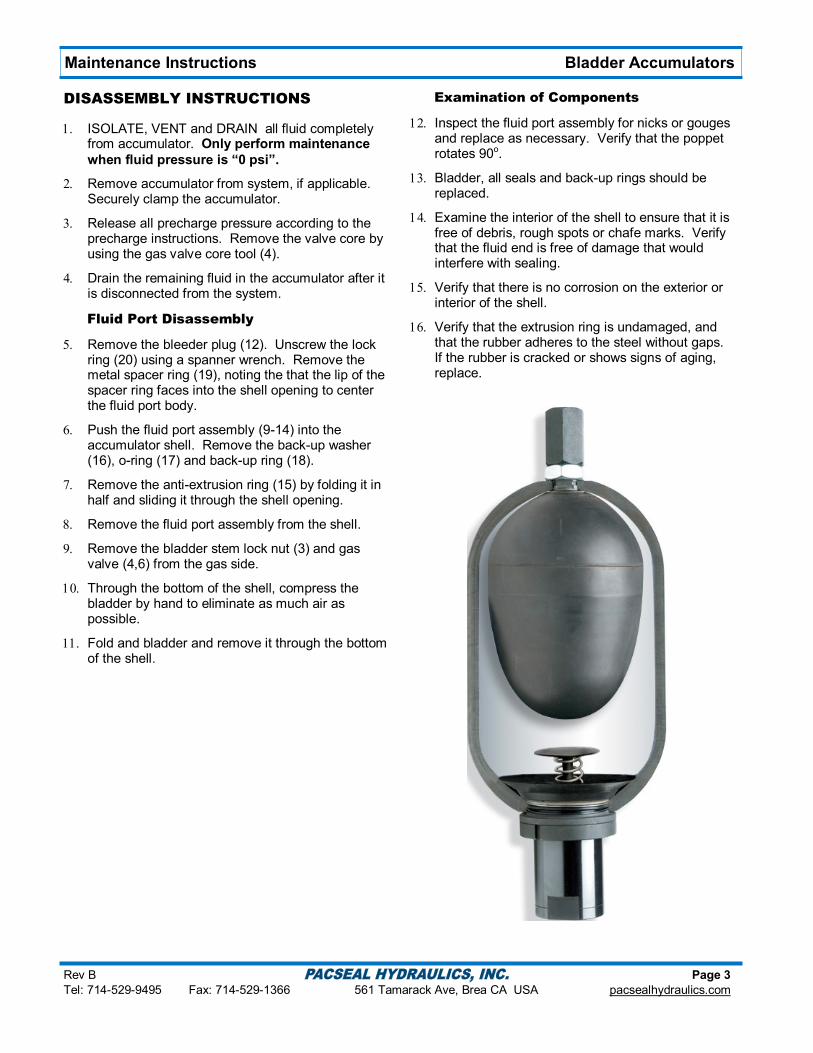
Examination of Components
Inspect the fluid port assembly for nicks or gouges and replace as necessary. Verify that the poppet rotates 90o.
Bladder, all seals and back-up rings should be replaced.
Examine the interior of the shell to ensure that it is free of debris, rough spots or chafe marks. Verify that the fluid end is free of damage that would interfere with sealing.
Verify that there is no corrosion on the exterior or interior of the shell.
Verify that the extrusion ring is undamaged, and that the rubber adheres to the steel without gaps. If the rubber is cracked or shows signs of aging, replace.
Rev B Page 4
Tel: 714-529-9495 Fax: 714-529-1366 561 Tamarack Ave, Brea CA USA pacsealhydraulics.com
Maintenance Instructions Bladder Accumulators
REASSEMBLY INSTRUCTIONS
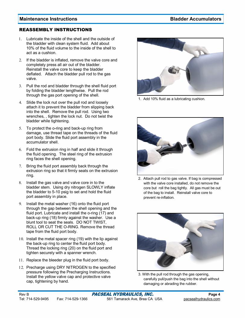
Lubricate the inside of the shell and the outside of the bladder with clean system fluid. Add about 10% of the fluid volume to the inside of the shell to act as a cushion.
If the bladder is inflated, remove the valve core and completely press all air out of the bladder. Reinstall the valve core to keep the bladder deflated. Attach the bladder pull rod to the gas valve.
Pull the rod and bladder through the shell fluid port by folding the bladder lengthwise. Pull the rod through the gas port opening of the shell.
Slide the lock nut over the pull rod and loosely attach it to prevent the bladder from slipping back into the shell. Remove the pull rod. Using two wrenches, , tighten the lock nut. Do not twist the bladder while tightening.
To protect the o-ring and back-up ring from damage, use thread tape on the threads of the fluid port body. Slide the fluid port assembly in the accumulator shell.
Fold the extrusion ring in half and slide it through the fluid opening. The steel ring of the extrusion ring faces the shell opening.
Bring the fluid port assembly back through the extrusion ring so that it firmly seats on the extrusion ring.
Install the gas valve and valve core in to the bladder stem. Using dry nitrogen SLOWLY inflate the bladder to 5-10 psig to set and hold the fluid port assembly in place.
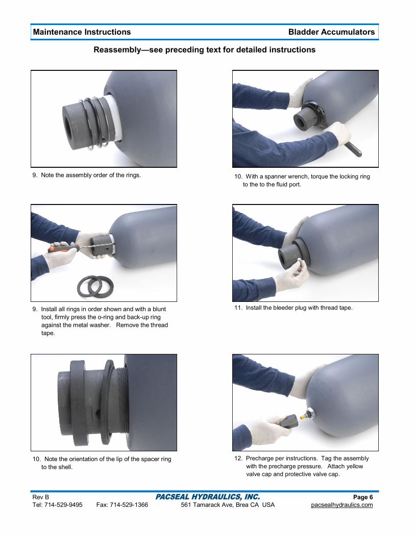
Install the metal washer (16) onto the fluid port through the gap between the shell opening and the fluid port. Lubricate and install the o-ring (17) and back-up ring (18) firmly against the washer. Use a blunt tool to seat the seals. DO NOT TWIST, ROLL OR CUT THE O-RING. Remove the thread tape from the fluid port body.
Install the metal spacer ring (19) with the lip against the back-up ring to center the fluid port body. Thread the locking ring (20) on the fluid port and tighten securely with a spanner wrench.
Replace the bleeder plug in the fluid port body.
Precharge using DRY NITROGEN to the specified pressure following the Precharging Instructions. Install the yellow valve cap and protective valve cap, tightening by hand.
1. Add 10% fluid as a lubricating cushion.
2. Attach pull rod to gas valve. If bag is compressed
with the valve core installed, do not remove the
core but roll the bag tightly. All gas must be out
of the bag to install. Reinstall valve core to
prevent re-inflation.
3. With the pull rod through the gas opening,
carefully pull/push the bag into the shell without
damaging or abrading the rubber.

Rev B Page 5
Tel: 714-529-9495 Fax: 714-529-1366 561 Tamarack Ave, Brea CA USA pacsealhydraulics.com
Maintenance Instructions Bladder Accumulators
Reassembly—see preceding text for detailed instructions
4. Loosely attach the attach the lock nut to the
bladder stem and remove the pull rod. Tighten
the lock nut with two wrenches, taking care not to
twist the bladder.
5. Apply thread tape on the outer threads of the fluid
port to protect the o-ring and back-up ring.
5. Slide the fluid port fully into the shell..
6. Fold the extrusion ring in half and slide it into the
shell opening with the steel ring facing the
opening.
7. Bring the fluid port back through the center of the
extrusion ring, firmly seating the ring to the shell.
8. Attach the gas charging assembly (see
precharge directions), and slowly inflate the
bladder to 5-10 psig in order to set and hold the
fluid port in place. Remove the charging
equipment.
Rev B Page 6
Tel: 714-529-9495 Fax: 714-529-1366 561 Tamarack Ave, Brea CA USA pacsealhydraulics.com
Maintenance Instructions Bladder Accumulators
9. Note the assembly order of the rings.
9. Install all rings in order shown and with a blunt
tool, firmly press the o-ring and back-up ring
against the metal washer. Remove the thread
tape.
10. Note the orientation of the lip of the spacer ring
to the shell.
10. With a spanner wrench, torque the locking ring
to the to the fluid port.
11. Install the bleeder plug with thread tape.
12. Precharge per instructions. Tag the assembly
with the precharge pressure. Attach yellow
valve cap and protective valve cap.
Reassembly—see preceding text for detailed instructions