Embed Size (px)
Citation preview

P/N 11995BSeptember 2005 V2
Engine Powered Gasoline
Battery Electric
Maintenance andRepair Parts

LIMITED WARRANTY
Snorkel warrants each new machine manufactured and sold by it to be free from defects in material and workmanship for aperiod of one (1) year from date of delivery to a Customer or for one year after the machine has been placed in first service in aDealer rental fleet, whichever comes first. Any part or parts which, upon examination by the Snorkel Service Department, arefound to be defective, will be replaced or repaired, at the sole discretion of Snorkel, through its local Authorized Dealer at nocharge.
Snorkel further warrants the structural components; specifically, the mainframe chassis, turntable, booms and scissor arms,of each new machine manufactured by it to be free from defects in material and workmanship for an additional period of four(4) years. Any such part or parts which, upon examination by the Snorkel Service Department, are found to be defective willbe replaced or repaired by Snorkel through its local Authorized Dealer at no charge; however, any labor charges incurred as a result of such replacement or repair will be the responsibility of the Customer or Dealer.
The Snorkel Service Department must be notified within forty-eight (48) hours of any possible warranty situation during theapplicable warranty period. Personnel performing warranty repair or replacement must obtain specific approval by SnorkelService Department prior to performing any warranty repair or replacement.
Customer and Dealer shall not be entitled to the benefits of this warranty and Snorkel shall have no obligations hereunderunless the “Pre-Delivery and Inspection Report” has been properly completed and returned to the Snorkel ServiceDepartment within ten (10) days after delivery of the Snorkel product to Customer or Dealer’s rental fleet. Snorkel must benotified, in writing, within ten (10) days, of any machine sold to a Customer from a Dealer’s rental fleet during the warrantyperiod.
At the direction of the Snorkel Service Department, any component part(s) of Snorkel products to be replaced or repairedunder this warranty program must be returned freight prepaid to the Snorkel Service Department for inspection. All warrantyreplacement parts will be shipped freight prepaid (standard ground) from the Snorkel Service Department or from Snorkel’sVendor to Dealer or Customer.
REPLACEMENT PARTS WARRANTY
Any replacement or service part made or sold by Snorkel is not subject to the preceding Limited Warranty beyond thenormal warranty period of the machine upon which the part was installed.
THIS WARRANTY EXCLUDES AND SNORKEL DOES NOT WARRANT:
1. Engines, motors, tires and batteries which are manufactured by suppliers to Snorkel, who furnish their own warranty.Snorkel will, however, to the extent permitted, pass through any such warranty protection to the Customer or Dealer.
2. Any Snorkel product which has been modified or altered outside Snorkel’s factory without Snorkel’s written approval, ifsuch modification or alteration, in the sole judgment of Snorkel’s Engineering and/or Service Departments, adverselyaffects the stability, reliability or service life of the Snorkel product or any component thereof.
3. Any Snorkel product which has been subject to misuse, improper maintenance or accident. “Misuse” includes but isnot limited to operation beyond the factory-rated load capacity and speeds. “Improper maintenance” includes but is not limited to failure to follow the recommendations contained in the Snorkel Operation, Maintenance, Repair PartsManuals. Snorkel is not responsible for normal maintenance, service adjustments and replacements, including but notlimited to hydraulic fluid, filters and lubrication.
4. Normal wear of any Snorkel component part(s). Normal wear of component parts may vary with the type application ortype of environment in which the machine may be used; such as, but not limited to sandblasting applications.
5. Any Snorkel product that has come in direct contact with any chemical or abrasive material.
6. Incidental or consequential expenses, losses, or damages related to any part or equipment failure, including but notlimited to freight cost to transport the machine to a repair facility, downtime of the machine, lost time for workers, lostorders, lost rental revenue, lost profits or increased cost.
This warranty is expressly in lieu of all other warranties, representations or liabilities of Snorkel, either expressed or implied,unless otherwise amended in writing by Snorkel’s President, Vice President-Engineering, Vice President-Sales or VicePresident-Marketing.
SNORKEL MAKES NO WARRANTIES WHICH EXTEND BEYOND THE DESCRIPTION OF THIS LIMITED WARRANTY.SNORKEL MAKES NO IMPLIED WARRANTY OF MERCHANTABILITY OR FITNESS FOR A PARTICULAR PURPOSEAND DISCLAIMS ALL LIABILITY FOR INCIDENTAL OR CONSEQUENTIAL DAMAGES, INCLUDING BUT NOTLIMITED TO INJURY TO PERSONS OR PROPERTY.
The Customer shall make all warranty claims through its local Authorized Dealer and should contact the Dealer from whomthe Snorkel product was purchased for warranty service. Or, if unable to contact the Dealer, contact the Snorkel ServiceDepartment for further assistance.
Effective July 1995
© Snorkel – all rights reserved Printed in New Zealand

MHP15J – 11995B page 1
Table of Contents
General Specifications
General Specifications . . . . . . . . . . . . . . . . . . . . . . . . 3
Engine Specifications . . . . . . . . . . . . . . . . . . . . . . . . . 3
Working Envelope. . . . . . . . . . . . . . . . . . . . . . . . . . . . 4
Table of Contents
Maintenance Information
About this Manual: . . . . . . . . . . . . . . . . . . . . . . . . . . . 5
Manual Organization. . . . . . . . . . . . . . . . . . . . . . . . . . 5
General Specifications. . . . . . . . . . . . . . . . . . . . . . . 5
Maintenance . . . . . . . . . . . . . . . . . . . . . . . . . . . . . . 5
Repair parts and illustrations. . . . . . . . . . . . . . . . . . 5
Hydraulics . . . . . . . . . . . . . . . . . . . . . . . . . . . . . . . . 5
Electrical . . . . . . . . . . . . . . . . . . . . . . . . . . . . . . . . . 5
Options. . . . . . . . . . . . . . . . . . . . . . . . . . . . . . . . . . . 5
Parts index - Page locator . . . . . . . . . . . . . . . . . . . . 5
Maintenance and Schematics. . . . . . . . . . . . . . . . . . . 5
Maintenance information . . . . . . . . . . . . . . . . . . . . . 5
Maintenance schedules . . . . . . . . . . . . . . . . . . . . . . . 6
Daily Maintenance . . . . . . . . . . . . . . . . . . . . . . . . . . . 7
Pre-operational Inspection. . . . . . . . . . . . . . . . . . . . 7
Hydraulic Hose Age . . . . . . . . . . . . . . . . . . . . . . . . . . 7
90 Day or 150 Hour Maintenance(Trained Service Technician) . . . . . . . . . . . . . . . . . 8
Yearly or 500 Hour Maintenance (Trained Service Technician) . . . . . . . . . . . . . . . . . 8
Lubricants . . . . . . . . . . . . . . . . . . . . . . . . . . . . . . . . . . 9
Pressure gun application . . . . . . . . . . . . . . . . . . . . . 9
Rotation bearing . . . . . . . . . . . . . . . . . . . . . . . . . . . 9
Rotation gear teeth and pinion . . . . . . . . . . . . . . . . 9
Engines . . . . . . . . . . . . . . . . . . . . . . . . . . . . . . . . . . 9
Hydraulic oil reservoir . . . . . . . . . . . . . . . . . . . . . . . 9
Battery . . . . . . . . . . . . . . . . . . . . . . . . . . . . . . . . . . . . 10
Preventive inspection maintenance90 day or 150 hour checklist . . . . . . . . . . . . . . . . . 11
Torque chart . . . . . . . . . . . . . . . . . . . . . . . . . . . . . . . 13
To order service or repair parts . . . . . . . . . . . . . . . . 14
ANSI and OSHA compliance. . . . . . . . . . . . . . . . . 14
Manuals . . . . . . . . . . . . . . . . . . . . . . . . . . . . . . . . 14
Section 1. - Repair Parts
Trailer assembly . . . . . . . . . . . . . . . . . . . . . . . . . . . 1-2
Trailer assembly illustration. . . . . . . . . . . . . . . . . . . 1-3
Boom assembly illustration . . . . . . . . . . . . . . . . . . . 1-4
Boom assembly . . . . . . . . . . . . . . . . . . . . . . . . . . . . 1-5
Platform assembly . . . . . . . . . . . . . . . . . . . . . . . . . . 1-6
Motor assembly . . . . . . . . . . . . . . . . . . . . . . . . . . . . 1-7
Column assembly . . . . . . . . . . . . . . . . . . . . . . . . . . 1-8
Column assembly illustration. . . . . . . . . . . . . . . . . . 1-9
Placards and decals installation . . . . . . . . . . . . . . 1-10
2000kg axle . . . . . . . . . . . . . . . . . . . . . . . . . . . . . . 1-12
2000kg axle assembly illustration . . . . . . . . . . . . . 1-13
Levelling assembly illustration. . . . . . . . . . . . . . . . 1-14
Levelling Assembly . . . . . . . . . . . . . . . . . . . . . . . . 1-15

page 2 MHP15J – 11995B
Table of Contents
Section 3. - Electrical
Electrical schematic illustration . . . . . . . . . . . . . . . . 3-3
AC motor option wiring schematic illustration . . . . . 3-4
Road transport electric illustration. . . . . . . . . . . . . . 3-5
Upper control box assembly . . . . . . . . . . . . . . . . . . 3-6
Lower control box assembly . . . . . . . . . . . . . . . . . . 3-7
Section 2. - Hydraulics
Hydraulic schematic illustration for standard units . 2-3
Main control valve - sheet 1 . . . . . . . . . . . . . . . . . . 2-4
Main control valve - sheet 2 . . . . . . . . . . . . . . . . . . 2-5
Upper boom lift cylinder assembly . . . . . . . . . . . . . 2-6
Lower boom lift cylinder assembly . . . . . . . . . . . . . 2-7
Flyboom cylinder assembly . . . . . . . . . . . . . . . . . . . 2-8
Stabiliser leg cylinder assembly . . . . . . . . . . . . . . . 2-9
Oil distributor assembly - 3 port. . . . . . . . . . . . . . . 2-11
Oil distributor assembly 3 port illustration . . . . . . . 2-12
Distributor 3 port . . . . . . . . . . . . . . . . . . . . . . . . . . 2-13
Section 4. - Options
Rotator option . . . . . . . . . . . . . . . . . . . . . . . . . . . . . 4-2
Rotator option illustration. . . . . . . . . . . . . . . . . . . . . 4-3

General Specifications
n General Specifications
n Engine Specifications
MHP15J – 11995B page 3
SPECIFICATIONS MHP15J
Nominal working height 14.8m 48’ 7”
Maximum height to basket floor 13m 42’ 6”
Maximum outreach 6.8m 22’ 8”
Maximum outreach height 6.90m 22’ 6”
Maximum width of base
Stabilisers retracted
Stabilisers extended
1.75m
3.53m
5’ 7”
11’ 5”
Safe working load (unrestricted) 200kg 440lbs
Standard colour Orange base/boom grey platform
Platform size 1200 x 760 x 1100mm
Aluminum
4’ x 2’ 6” x 3’ 7”
Aluminum
Travelling height 1.82m 5’ 9”
Overall length 7553mm 25’
Maximum towing speed 80km/h 50m/h
Turntable rotation 360o continuous
Trailer tongue weight 100kg 220lb
Engine Make Honda (gas o line)
Model GX 160
Engine type 4-stroke, over head valve, 1 cylinder
Displacement 163 cm3 (9.9 cu-in)
Bore x Stroke 68 x 45 mm (2.7 x 1.8 in)
Max. output 4 kW/4,000 rpm
Max. torque 1.1 kg-m (8.0 ft-lb)/ 2500 rpm
Fuel gasoline
Fuel Grade automotive gasoline (unleaded or lowleaded preferred)
Fuel consumption 230 g/PSh
Cooling system Forced air
Ignition system Transistor magneto
PTO shaft rotation Counterclockwise
Oil Capacity 0.60 litres (0.60 US qt, 0.53 Imp qt)
Oil Grade SAE 10W-30

n Working Envelope
page 4 MHP15J – 11995B
General Specifrications
16 (52.4)
15 (49.2)
14 (45.9)
13 (42.6)
12 (39.3)
11 (36.1)
10 (32.8)
9 (29.5)
8
8
(26.2)
(26.2)
7
7
(22.9)
(22.9)
6
66
(19.6)
(19.6)(19.6)
5
55
(16.4)
(16.4)(16.4)
4
44
(13.1)
(13.1)(13.1)
3
33
(9.8)
(9.8)(9.8)
2
22
(6.5)
(6.5)(6.5)
1
11
(3.2)(3.2)
00
(0)
(0)
MET
RES
METRES
FEET
FEET

Maintenance Information
n About this Manual:
This Maintenance and Repair Parts manual coverscurrent production machines only.
While Snorkel has attempted in every way toconfirm that all information in this manual is correct, improvements are being constantly made to themachine that may not be reflected in this manual.
NOTE:
It is recommended that you record the serial andmodel number of your machine (see page 14 of this chapter). This information is found on the serialnumber placard.
n Manual Organization
The Repair Parts Manual consists of five sectionswith an individual table of contents precedingsections 1 through 4.
Subassemblies and detailed parts are identified byindex numbers on the illustrations that correspondto the item numbers on the parts listing. Whenrequesting any part, always specify complete partnumber, description, model and serial number ofyour unit.
The following is a general description of eachsection and its contents.
q General Specifications
The section immediately preceding, containsinformation relating to the general specifications ofthe MHP15J.
q Maintenance
The pages immediately following, containinformation as to the maintenance schedules -lubricants and procedures for proper lubrication ofthe unit.
q Repair parts and illustrations
Repair Parts (Section 1), contains parts listingsand illustrations for general mechanical repairparts of all major installations and subassembliesof the unit.Hydraulics
q Hydraulics
(Section 2), contains parts listings and illustrationsof hydraulic components installations includinghydraulic schematics and individual componentssuch as cylinders, controls valves and solenoidoperated valves.
q Electrical
Electrical (Section 3), contains listings andillustrations of electrical components installationsincluding wiring schematics.
q Options
Options (Section 4), contains parts listings andillustrations of optional installations that may beinstalled on your unit.
q Parts index - Page locator
The parts index - page locator, identifies thecomponent by name and directs you to the sectionand page number where you may find informationfor that part such as its part order number, etc.
n Maintenance and Schematics
q Maintenance information
The parts drawings located in the repair partssections, are designed for use as a guide for proper disassembly of the machine and components aswell as for parts replacement. Always refer to thehydraulic system installation drawings and theelectrical wiring diagram before removing ordisassembling associated parts.
Do not attempt to disconnect or remove anyhydraulic l ine before reading andunderstanding all text concerning thesystem hydraulics. In most cases,disassembly of the machine will be obviousfrom the illustration.
DO NOT mod ify this ariel plat form with outprior writ ten con sent of Snor kel En gi neering De part ment.
Mod i fi ca tion may void the war ranty,ad versely af fect sta bil ity, or af fect theop er a tional char ac ter is tics of the arielplat form.
When disassembl ing or reassembl ingcomponents, complete the procedural steps insequence. Do not partially disassemble orassemble one part, then start on another. Alwayscheck your work to assure that nothing has beenoverlooked.
The following list is a gentle reminder whendisassembling or assembling the machine.
MHP15J – 11995B page 5
CAUTION
CAUTION
ü Always be conscious of weight.
ü Never attempt to lift heavy objects without the aid ofa mechanical device.
ü Do not allow heavy objects to rest in an unstablecondition.
ü Always make sure work platform is in stowedposition - blocked or the weight removed by asuitable lifting device before disconnecting thehydraulic hose from the motor/pump unit to the liftcylinder.
üWhen raising a portion of the machine, be sure thatadequate blocking is properly positioned - Do notdepend on lifting device to hold and secure weight.
ü If a part resists removal, check to see if all fasteners, electrical wiring, hydraulic lines, etc., have beenremoved or that other parts are not interfering.
Parts should be thoroughly inspected beforerestoring to service at the time of reassembly. Burrs, nicks or scratches may be removed from machinedsurfaces by honing or polishing with #600 crocuscloth, followed by a thorough cleaning in anapproved cleaning solvent, and blown dry withcompressed air. Do not alter the contour of any part.If this operation does not restore the part to aserviceable condition, replace the part.
Replace all O-rings, seals, and gaskets atreassembly. Use new roll pins or cotter pins. Dip allpacking rings and seals in hydraulic oil beforereassembling in cylinder and manifold installations.Replace any part having imperfect threads. Ingeneral, units that have been disassembled can bereassembled by reversing the order of disassembly.
Remember that the service life of a machine can beincreased by keeping dirt and foreign materials outof the vital components. Precautions have beentaken to safeguard against this; shields, covers,seals and filters are provided to keep air and oilsupplies clean; however, these items must bemaintained on a scheduled basis in order to function properly.
At any time air or oil lines are disconnected, cleansurrounding areas as well as the opening andfittings themselves. As soon as a line or componentis disconnected, cap or cover all openings toprevent the entry of dirt or foreign materials.
New parts should remain in their container until theyare ready to be used.
Clearly mark or tag hydraulic lines and electricalwiring connections when disconnecting or removing them from unit. This will assure that they arecorrectly reinstalled.
Proper assembly is critical to the successfulrebuilding of any unit. Carefully inspect any partswhich are to be reused. If in doubt, replace.
“SAFETY FIRST” is a good slogan.
Replace any guards and protective devices thathave been removed to carry out maintenance andrepair work.
n Maintenance schedules
Snorkel has established a Preventive MaintenanceSchedule that includes:
ü Daily Maintenance (Operator’s Inspection)
ü 90 Day or 150 Hour (frequent) Maintenance
ü Yearly or 500 Hour (annual) Maintenance,
These schedules should ensure the detection of any defective, damaged or improperly secured partsand provide information regarding lubrication andother minor maintenance items.
The Maintenance Schedule following, outlines therequirements of these maintenance checks for each time interval. The Operator’s Pre-operationalinspection must be performed by a trained operator.All other maintenance and inspections must beperformed by a trained service technician only.
Note that the 90 Day or 150 hour (frequent) andyearly or 500 hour (annual) Maintenance, requireuse of the Preventive Inspection MaintenanceChecklist to pinpoint all inspection items. Retain acopy of these forms for your records.
They also require that all placards and decals on theunit are to be inspected.
All placards and decals must be in place and legible. Use the placards installation drawing and partslisting in the repair parts section 1 of this manual tocheck these placards and decals.
Snorkel recommends that you make additionalcopies of the Preventive Inspection MaintenanceChecklist forms for your use in performing these
Failure to perform the PreventiveMaintenance at the intervals outlined in theMaintenance Schedule may result in a unitbeing operated with a defect that could resultin INJURY or DEATH of the unit operator. DONOT allow a unit to be operated that has beenfound to be defective.
Repair all defects before returning the unit toservice.
page 6 MHP15J – 11995B
Maintenance Information
DANGER

n Daily Maintenance
MHP15J – 11995B page 7
Maintenance Information
q Pre-operational Inspection
Item Service Required
Engine fuel level Look to see that the fuel tank is full
Fuel tank cap Check to see that the cap is tight
Engine oil level Check oil level (between dipstick lines)
Fuel leaks Visually inspect (hoses and connections)
Engine cooling Check that grills are not blocked
Wiring harnesses Visually inspect (installation, condition)
Battery terminals Visually inspect (no corrosion)
Battery fluid level Check fluid level (1/4" or 6 mm below filler neck)
Hydraulic oil level Visually inspect level (between lines on gauge)
Hydraulic oil leaks Visually inspect (hoses, tubes)
Tires and wheels Visually inspect (condition)
Bolts and fasteners Visually inspect (condition)
Structural damage and welds Visually inspect (weld cracks, dents)
Lanyard anchor points Visually inspect (condition)
Platform gravity gate Check condition and operation
Platform guardrails Visually inspect (condition)
Flashing light (option) Visually inspect (operation)
Ground control switches Actuate and inspect for proper operation
Emergency lower Check operation (causes correct motion)
n Hydraulic Hose Age
EN982 Clause 7.3.1 requires the manufacturing date of each hydraulic hose to be clearly visible on thehose.
Hoses used in production of this unit are manufactured by Parker and the manufacturing date is present ina coded format.
The key to decode the date is as follows:
11 - 4Q 9911- 4Q 99
Manufacturing Plant Number
Sample Hose Code
Year of Manufacture
Manufacturing Period (i.e. 4th Quarter)
page 8 MHP15J – 11995B
Maintenance Information
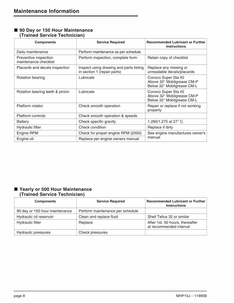
n 90 Day or 150 Hour Maintenance(Trained Service Technician)
Components Service Required Recommended Lubricant or FurtherInstructions
Daily maintenance Perform maintenance as per schedule
Preventive inspectionmaintenance checklist
Perform inspection, complete form Retain copy of checklist
Placards and decals inspection Inspect using drawing and parts listing in section 1 (repair parts)
Replace any missing orunreadable decals/placards
Rotation bearing Lubricate Conoco Super Sta #2Above 32° Mobilgrease CM-PBelow 32° Mobilgrease CM-L
Rotation bearing teeth & pinion Lubricate Conoco Super Sta #2Above 32° Mobilgrease CM-PBelow 32° Mobilgrease CM-L
Platform rotator Check smooth operation Repair or replace if not workingproperly
Platform controls Check smooth operation & speeds
Battery Check specific gravity 1.260/1.275 at 27° C.
Hydraulic filter Check condition Replace if dirty
Engine RPM Check for proper engine RPM (2500) See engine manufactures owner's manualEngine oil Replace per engine owners manual
n Yearly or 500 Hour Maintenance (Trained Service Technician)
Components Service Required Recommended Lubricant or FurtherInstructions
90 day or 150 hour maintenance Perform maintenance per schedule
Hydraulic oil reservoir Clean and replace fluid Shell Tellus 32 or similar
Hydraulic filter Replace After 1st. 50 hours, thereafterat recommended interval
Hydraulic pressures Check pressures

n Lubricants
Specific lubricants as recommended by Snorkel,should be used in maintaining your unit. If in doubtregarding the use of lubricants other than thoselisted, contact Snorkel.
q Pressure gun application
Service all fittings as indicated in the MaintenanceSchedule and lubrication illustration. Wipe away all excess lubricant from exposed surfaces. Overlubrication can collect dirt and foreign matter whichacts as an abrasive. Lubrication of accessoryequipment should be in accordance with themanufacturer’s recommendations.
q Rotation bearing
Rotation bearing. Pressure gun lubricate bearingat recommended interval using lubricant asoutlined in the maintenance schedule. Rotate while lubricating. Lubrication fitting is located on the fontplate of the turntable.
q Rotation gear teeth and pinion
Rotation gear teeth and pinion. Gear teeth andgear box pinion should be lubricated with a multipurpose grease.
q Engines
Engine. Refer to the engine manufacturer’sinstruction manual or consult your local engineservice representative if engine adjustments orrepairs are needed. The engine MUST be operated in accordance with manufacturer’s instructions and serviced at recommended intervals.
q Hydraulic oil reservoir
Hydraulic oil reservoir. The fluid level should bekept between the low and full marks on the dipstickand should be checked with all cylinders fullyretracted and the platform in stowed position.
It is absolutely necessary that only new, cleanhydraulic oil is added.
If it becomes necessary to add or use an oilother than the recommended fluid, it isimportant that it be compatible andequivalent to the factory fill. Local oilsuppliers can generally furnish thisinformation.
If questions still remain, contact Snorkel for furtherinformation.
MHP15J – 11995B page 9
Maintenance Information
CouplingMulti purpose
grease onshaft
Rotation bearing(2 points)
Rotation gearteeth and
pinion
Knuckle pinMP grease
Hydraulic oil reservoirand filter
RHS of Trailer
The illustration locates the lubrication points of the MHP15J.
CAUTION

n Battery
Battery. The battery will have longer life if the waterlevel is maintained and it is kept charged. The unitwill have better starting characteristics with a fullycharged battery.
In cold weather the battery should be maintained atfull charge to keep from freezing. An extremely lowor dead battery can freeze in cold weather. Makesure connections are clean and tight.
Make sure charging equipment is operatingproperly.
Lead-acid batteries contain sulfuric acidwhich will damage eyes or skin on contact.When working around batteries, ALWAYSwear a face shield to avoid acid in eyes.
If acid contacts eyes, flush immediately withclear water and get medical attention.
Wear rubber gloves and protective clothingto keep acid off skin, if acid contacts skin,wash off immediately with clear water.
Lead-acid batteries produce flammable andexplosive gases. NEVER allow smoking,flames or sparks around batteries.
page 10 MHP15J – 11995B
Maintenance Information
DANGER

Inspection Procedures Codes
(1) Weld cracks, dents and/or rust
(2) Installation
(3) Leaks
(4) Operation
(5) Condition
(6) Tightness
(7) Residue buildup
(8) See placards and decals inspection chart
Check OK 4 X
Chassis
Structural (1)Tires (5)
Tire pressure (5)
Hydraulic tubes and hoses (3,5)Decals and placards (2,8)
Wheel nuts (6) Torque 95lbft 130NM
Battery disconnect switch (4)Lubrication points
Pins, pin keepers (2)
TurntableStructural (1)
Swivel mount assembly (2,3)
Hydraulic tubes and hoses (3,5)Cowling (5,6)
Wire harness (2,5)System pressure (Max 2500 psi)
Lubrication points
Emergency bleed down valve (4,3)Engine (2,4)
Engine charging system (4)
Engine air filter (5)Hydraulic pump (4)
Engine oil (5)Electric choke (4)
Hydraulic oil reservoir (2,3,5)
Hydraulic oil reservoir filler/breather cap (2,6)Hydraulic oil reservoir fluid level (5)
Hydraulic oil return filter (3,4)
Pins, pin keepers (2)
Lower BoomsStructural (1)
Boom lift cylinder pin caps (2,6)Boom lift cylinder and holding valve (3,4)
Jib cylinder pin (3,4)
Hydraulic tubes and hoses (3,5)Electrical Wires (5,2)
Upper Booms
Structural (1)Electrical wires (5)
Jib cylinder pin caps (2,6)
Jib cylinder and holding valve (3,4)Hydraulic hoses and tubes (3,5)
Decals and placards (2,8)
Platform rotator (Optional) (3,4)
Check OK 4 X
Platform rotation holding valve (3,4)Rotator mounting bolts (2,6)
Platform
Structural (1)Decals and placards (2,8)
Platform gate (4)
Hydraulic tubes and hoses (3,5)Platform mounting bolts (2,6)
Correct operator's manual in document holder (2)
BatteryBattery terminals (6,7)
Battery electrolyte level (5)
Fuel Tank
Fuel tank (3,5)Fuel tank cap (2,3,4,5)
Ground Control Station
Station selector switch - ground controlsplatform controls DO NOT work (4)
Station selector switch - platform controlsground controls DO NOT work (4)
Cold start (4) ChokeKeyed master switch (4)
Boom speed rheostat switch (4)
Turntable rotation (4)Upper boom lift UP - DOWN (4)
Lower boom lift UP - DOWN (4)
Jib boom lift UP - DOWN (4)Emergency stop (4)
Platform Control Station
Foot switch (4)Foot switch, functions operate when engaged (4)
Anti-restart switch (4)
Cold start (4) ChokeBoom speed rheostat switch (4)
Turntable rotation (4)Upper boom lift UP - DOWN (4)
Lower boom lift UP - DOWN (4)
Jib boom lift UP - DOWN (4)Emergency stop (4)
Optional Equipment
Air line to platform (2,4)Dual fuel system (2,4)
Platform work lights (2,4)
Platform rotation (4)
MHP15J – 11995B page 11
Maintenance Information
n Preventive inspection maintenance90 day or 150 hour checklist
OK OK - No Service Required Serial Number4 Corrective Action Required
X Corrected, (Record description of corrective action).

page 12 MHP15J – 11995B
Maintenance Information
Corrective Action Required
Note: If correction action is required on any item, attach sheet indicating problem and action taken.
All items have been properly checked and tested and found to be operating satisfactory or necessary correctiveaction has been completed.
Inspected By: Date

MHP15J – 11995B page 13
Maintenance Information
5.03 6.78 8.7814.220.1
M3 x 0.5M3.5 x 0.6M4 x 0.7M5 x 0.8M6 x 1
M8 x 1.25M8 x 1M10 x 1.5M10 x 1.25
Grade marking M8.8 M10.9 M12.9
LUBEDk=0.15
DRYk=0.20
TORQUE (N.m)NOM SIZEX
PITCH
CLAMPLOAD
W(N)
PROPERTY CLASS 8.8TENSILESTRESS
AREAAs
2(mm )
PROPERTY CLASS 10.9
CLAMPLOAD
W(N)
TORQUE (N.m)
DRYk=0.20
LUBEDk=0.15
36.6 39.2 58.0 61.2
2 2002 9603 8306 2008 770
1.32 2.07 3.07 6.2010.5
0.991.552.304.657.90
2 990 4 030 5 220 8 43011 950
1.79 2.82 4.17 8.4314.3
1.34 2.11 3.13 6.3310.8
15 97517 10025 32526 725
25.6 27.4 51 53
19.220.538.040.1
21 75023 27534 45036 350
34.837.36973
26.127.95255
M12 x 1.75M12 x 1.25M14 x 2M14 x 1.5
84.3 92.1115125
36 80040 20050 20054 550
88 96140155
66 72105115
50 07554 70068 30074 250
120130190210
90 98145155
M16 x 2M16 x 1.5M20 x 2.5M20 x 1.5
157167245272
68 525 72 900106 950118 750
220235430475
165175320355
93 250 99 200145 550161 550
300320580650
225240435485
M24 x 3M24 x 2M27 x 3M27 x 2
353384459496
154 100167 600200 350216 500
740 8051 0801 170
555605810875
209 700228 100272 650294 600
1 0101 1001 4701 590
755 8201 1001 150
M30 x 3.5M30 x 3M30 x 2M33 x 3.5M33 x 2
561580621694761
244 900253 150271 050302 950332 200
1 4701 5201 6302 0002 200
1 1001 1401 2201 5001 640
333 250344 500368 850412 250452 050
2 0002 0702 2102 7202 980
1 5001 5501 6602 0402 240
M36 x 4M36 x 3M39 x 4M39 x 3
817 865 9761 028
356 600377 600426 000448 700
2 5702 7203 3203 500
1 9302 0402 4902 630
485 300513 800579 750610 650
3 4903 7004 5204 760
2 6202 7803 3903 570
M42 x 4.5M42 x 3M45 x 4.5M45 x 3M48 x 5M48 x 3
1 1211 2061 3061 3981 4731 604
489 300526 400570 050610 250642 950700 150
4 1104 4205 1305 4906 1706 720
3 0803 3203 8504 1204 6305 040
665 850716 350775 750830 400874 950952 800
5 5906 0206 9807 4708 4009 150
4 2004 5105 2405 6106 3006 860
n Torque chart

n To order service or repair parts
When placing an order for service or repair parts,please have the following information available foryour machine.
ü Machine model number
ü Machine serial number
ü Snorkel part number
ü Description of part
ü Quantity of parts required
ü Your purchase order number
ü Address for order to “Ship To”
ü Your desired shipment method
All correspondence relative to this unit, such as fieldreports, discrepancy reports, requests for serviceinformation, etc., should be directed to:
Snorkel36 Bruce RoadP.O. Box 1041Levin 5500New Zealand
Phone: +64 06 368-9168Fax: +64 06 368-9164
Attention: Parts Department
q ANSI and OSHA compliance
All owners and users of the aerial platform mustread, understand, and comply with all applicableregulations. Ultimate compliance to OSHAregulations is the responsibility of the user and theiremployer.
ANSI publ icat ions c lear ly ident i fy theresponsibilities of all personnel who may beinvolved with the aerial platform. A reprint of the“Manual of Responsibilities for Dealers, Owners,Users, Operators, Lessors and Lessees ofANSI/SIA A92.5-1992 Boom-Supported ElevatingWork Platforms” is available from Snorkel dealers or from the factory upon request.
Copies are also available from:
Scaffold Industry Association20335 Ventura Blvd. Suite 310Woodland Hills, CA 91364-2471 USA
q Manuals
Manuals are available from Snorkel to support anyof the machines that we produce.
The specific manuals for MHP15J are as follows:
ü Operator’s ManualSnorkel part number - 11995A
ü Repair Parts ManualSnorkel part number - 11995B
page 14 MHP15J – 11995B
Maintenance Information
Record machine information here:
Model number*
Serial number*
Date of purchase
Purchased from
Snorkel dealer or distributor
* This information is found on the serial number placard attached to your machine.

Section 1
Trailer assembly . . . . . . . . . . . . . . . . . . . . . . . . . . . 1-2
Trailer assembly illustration. . . . . . . . . . . . . . . . . . . 1-3
Boom assembly illustration . . . . . . . . . . . . . . . . . . . 1-4
Boom assembly . . . . . . . . . . . . . . . . . . . . . . . . . . . . 1-5
Platform assembly . . . . . . . . . . . . . . . . . . . . . . . . . . 1-6
Motor assembly . . . . . . . . . . . . . . . . . . . . . . . . . . . . 1-7
Column assembly . . . . . . . . . . . . . . . . . . . . . . . . . . 1-8
Column assembly illustration. . . . . . . . . . . . . . . . . . 1-9
Placards and decals installation . . . . . . . . . . . . . . 1-10
2000kg axle . . . . . . . . . . . . . . . . . . . . . . . . . . . . . . 1-12
2000kg axle assembly illustration . . . . . . . . . . . . . 1-13
Levelling assembly illustration. . . . . . . . . . . . . . . . 1-14
Levelling Assembly . . . . . . . . . . . . . . . . . . . . . . . . 1-15
MHP15J – 11995B page 1 - 1
Section 1. - Repair Parts

Trailer assembly
Item Part No Qty Description
1. 9844J 1 Trailer weld2. 10929 1 Drawbar weld3. 10408 4 Stabiliser weld4. 10275A 4 Stabiliser cylinder5. 1045 1 Jockey wheel6. 1038 1 Tow coupling7. 9846 4 Foot plate8. 9948 4 Pin, foot plate9. 8628 4 Pin keeper, 6mm
10. 10293 4 Pin, cylinder to stabiliser11. 8626 8 Pin keeper, 10mm12. 1771 1 Boom lock pin13. 10277-2 4 Cylinder cover14. 10291 4 Pin, stabiliser to housing15. 9981 4 Pressure switch16. 10142 4 Microswitch17. 9844-10 4 Bracket, mudguard18. 8024R-15 1 Right hand mudguard19. 9863 1 Engine cover20. 8773 1 Oil tank21. 7886 1 Dipstick22. 11956A 1 Oil distributor23. 9887 1 Leg control valve24. 9869 2 Mudflap25. 1704-004 2 Wheel rim26. 11027 1 Axle assembly27. 1704-005 2 Tyre28. 8024L-15 1 Left hand mudguard29. 9851-2 1 Floor plate, rear30. 9851-5 1 Floor plate, front31. 11492-1 8 Locktab, 6mm32. 11492-3 8 Locktab, 10mm
page 1 - 2 MHP15J – 11995B
Trailer assembly

TITLE
Page 1 - 3
Trailer Assembly
Snorkel model MHP15JDWG. 00000
1
931
27
23
11
24
13
14
29
3
17
18
21
20
19
4
15
16
2
12
26
10
7
8
28
25
6
22
30
5
32
Trailer assembly illustration

TITLE
Page 1 - 4
Boom Assembly
Snorkel model MHP15J DWG. 00000
9 10
10
14
27
13
19
25
25
2122
6
1
12
12
11
11
2
7
5
8
17
17
4
27
13
26
12
12
28
3
15
20
2423
26
24
2616
18
18
18
18
13
Boom assembly illustration
Boom assembly
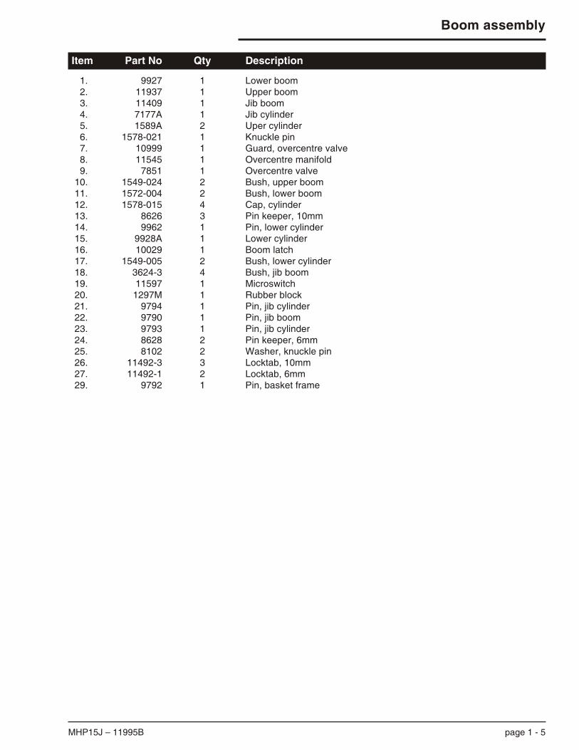
Item Part No Qty Description
1. 9927 1 Lower boom2. 11937 1 Upper boom3. 11409 1 Jib boom4. 7177A 1 Jib cylinder5. 1589A 2 Uper cylinder6. 1578-021 1 Knuckle pin7. 10999 1 Guard, overcentre valve8. 11545 1 Overcentre manifold9. 7851 1 Overcentre valve
10. 1549-024 2 Bush, upper boom11. 1572-004 2 Bush, lower boom12. 1578-015 4 Cap, cylinder13. 8626 3 Pin keeper, 10mm14. 9962 1 Pin, lower cylinder15. 9928A 1 Lower cylinder16. 10029 1 Boom latch17. 1549-005 2 Bush, lower cylinder18. 3624-3 4 Bush, jib boom19. 11597 1 Microswitch20. 1297M 1 Rubber block21. 9794 1 Pin, jib cylinder22. 9790 1 Pin, jib boom23. 9793 1 Pin, jib cylinder24. 8628 2 Pin keeper, 6mm25. 8102 2 Washer, knuckle pin26. 11492-3 3 Locktab, 10mm27. 11492-1 2 Locktab, 6mm29. 9792 1 Pin, basket frame
MHP15J – 11995B page 1 - 5
Boom assembly

page 1 - 6 MHP15J – 11995B
Platform assembly
Item Part No Qty Description
1. 11429 1 Platform weld2. 11455 1 Basket frame weld3. 11456 1 Bracket weld, frame mount4. 11456-4 As Req Level spacer5. 11461 1 Light, number plate6. 302-0021 1 Foot switch7. 11429-20 1 Gravity gate8. 11429-25 2 Bush, gravity gate9. 9876-4 2 Tail light
Platform assembly
8
7
5
9
31
4
2
6

Motor assembly
Item Part No Qty Description
1. 1171-4 1 Honda engine GX 1602. 1880-001 1 Coupling assy3. 10417 1 Bell housing (Metric shaft4. 1659 1 Pump5. 1171-4-6 1 Starter motor6. 7013-003 1 Fitting7. 7013-004 1 Fitting8. 7084-001 2 Dowty seal9. 1650-030 1 Battery lead
10. 1650-021 1 Earth lead
MHP15J – 11995B page 1 - 7
Motor assembly
CHALD
HOT
2
3
10
9
48
6
5
1
7
8

Column assembly
Item Part No Qty Description
1. 11940 1 Column weld2. 11406 1 Lower control box assembly3. 11390-6 1 Slew pinion cover4. 11942 1 Slew pinion gear5. 1067 1 Slew ring6. 9962 1 Pin, lower cylinder7. 9855-1 1 Cover, oil distributor8. 11415A 1 Control valve assembly9. 11597-1 1 Bracket, microswitch
10. 11597 1 Microswitch11. 11943 1 Slew motor and brake12. 9786 1 Pin, boom to column13. 9963 1 Pin, level rod14. 11505 Wiring harness, control valve15. 8626 2 Pin keeper, 10mm16. 8628 1 Pin keeper, 6mm17. 11492-3 2 Locktab, 10mm18. 11492-1 1 Locktab, 6mm
page 1 - 8 MHP15J – 11995B
Column assembly

MHP15J – 11995B page 1 - 9
Column assembly illustration
4
6
5
12
13
10
2
8
7
11
18
17
17
14
9 16
15
15
3
1
Column assembly illustration
Placards and decals installation
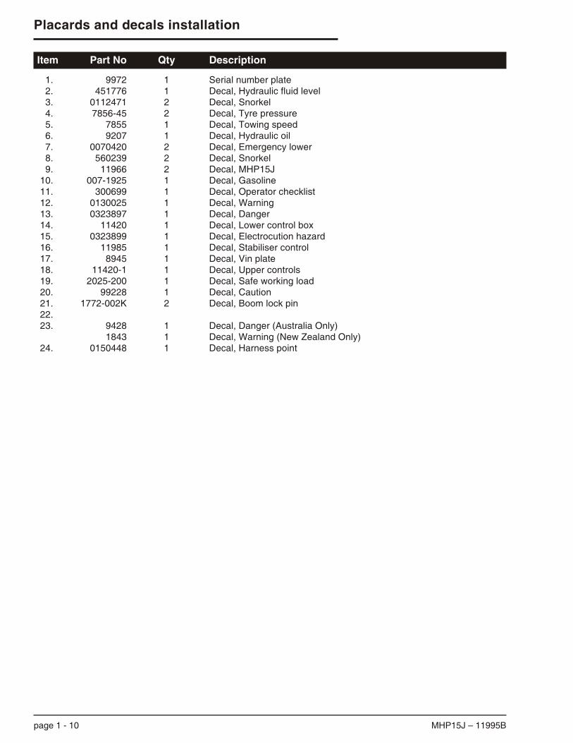
Item Part No Qty Description
1. 9972 1 Serial number plate2. 451776 1 Decal, Hydraulic fluid level3. 0112471 2 Decal, Snorkel4. 7856-45 2 Decal, Tyre pressure5. 7855 1 Decal, Towing speed6. 9207 1 Decal, Hydraulic oil7. 0070420 2 Decal, Emergency lower8. 560239 2 Decal, Snorkel9. 11966 2 Decal, MHP15J
10. 007-1925 1 Decal, Gasoline11. 300699 1 Decal, Operator checklist12. 0130025 1 Decal, Warning13. 0323897 1 Decal, Danger14. 11420 1 Decal, Lower control box15. 0323899 1 Decal, Electrocution hazard16. 11985 1 Decal, Stabiliser control17. 8945 1 Decal, Vin plate18. 11420-1 1 Decal, Upper controls19. 2025-200 1 Decal, Safe working load20. 99228 1 Decal, Caution21. 1772-002K 2 Decal, Boom lock pin22.23. 9428 1 Decal, Danger (Australia Only)
1843 1 Decal, Warning (New Zealand Only)24. 0150448 1 Decal, Harness point
page 1 - 10 MHP15J – 11995B
Placards and decals installation

MHP15J – 11995B page 1 - 11
Placards and decals installation
8
4 8 ,17
20
3
3
16
23
10
21
12
5
18
4
119
19
9
1
6
15, 14, 13
2
18
21
7
24

2000kg axle
Item Part No Qty Description
A. 11027 Ref Axle assembly1. 11027-7 2 Bearing cup2. 11027-8 2 Bearing cone3. 11027-1 2 Bearing cup4. 11027-2 2 Bearing cone5. 11027-9 2 Hub assembly (Includes 1, 5, 3, 25, 26)6. 11027-4 Ref Seal kit, hub9. 60030-075 2 Flat washer ¾” I.D.
10. 60021-092N 2 Castle nut ¾” U.N.F.11. 60038-043N 2 Split pin12. 11027-10 2 Grease cap13. 2045-001 Ref Caliper assembly, plated, no pads14. 9945-9 2 Anchor plate15. 2045K Ref Seal kit, caliper16. 11027-5 4 Brake pads17. 2045-003 2 Bleed screw18. 2045-13 2 Housing19. 11027-6 4 Guide pin20. 3605-08 4 Spring washer M821. 3610-08030 4 Set screw M8 x 30 HT22. 60005-013 2 Lockwasher23. 3610-12035 2 Set screw M12 x 35 HT24. 11027-11 2 Piston25. 11027-12 10 Wheel nut, .437” UNF 7/16”26. 11027-13 10 Wheel stud, .437” UNF 7/16”
page 1 - 12 MHP15J – 11995B
2000kg axle

13
5
12
9
10
1211
18
17
26
3
4
6
6
6
25
20
A
16
15
24
15
14
19
21
15
22
23
TITLE
Page 1 - 13
2000kg Axle Assembly
Hydraulic, Disc Brakes
Snorkel model MHP15JDWG. 000000
2000kg axle assembly illustration

TITLE
Page 1 - 14
Levelling Assembly
Snorkel model MHP15J DWG. 000000
9
8
6 15
8
19
13
2
11
19
23
13
11
18
19
8
10
13
19
13
7
19
16
11
10
18
13
11
12
316
17
1
11
5
4
9
9
14
17
Levelling assembly illustration

Levelling Assembly
Item Part No Qty Description
1. 9947 1 Lower level rod2. 11938 1 Upper level rod3. 11410 1 Jib level rod4. 11939 1 Jib level quadrant5. 9880 1 Guide channel6. 9951 1 Level quadrant7. 9879 1 Link level rod8. 3608-20 3 Lock nut9. 1750-120 3 Rod end
10. 9881 2 Roller11. 3624-8 5 Bush12. 9882 1 Pin13. 8628 5 Pin keeper, 6mm14. 1581-010 2 Bush15. 9932 1 Pin16. 7904 1 Overcentre cam17. 3624-3 2 Bush18. 9985 2 Pin19. 11492-1 5 Locktab, 6mm
MHP15J – 11995B page 1 - 15
Levelling Assembly


Section 2
Hydraulic schematic illustration for standard units . 2-3
Main control valve - sheet 1 . . . . . . . . . . . . . . . . . . 2-4
Main control valve - sheet 2 . . . . . . . . . . . . . . . . . . 2-5
Upper boom lift cylinder assembly . . . . . . . . . . . . . 2-6
Lower boom lift cylinder assembly . . . . . . . . . . . . . 2-7
Flyboom cylinder assembly . . . . . . . . . . . . . . . . . . . 2-8
Stabiliser leg cylinder assembly . . . . . . . . . . . . . . . 2-9
Oil distributor assembly - 3 port. . . . . . . . . . . . . . . 2-11
Oil distributor assembly 3 port illustration . . . . . . . 2-12
Distributor 3 port . . . . . . . . . . . . . . . . . . . . . . . . . . 2-13
MHP15J – 11995B page 2 - 1
Section 2. - Hydraulics

page 2 - 2 MHP15J – 11995B

Page 2 - 3
Hydraulic schematic for
standard machines
Snorkel model MHP15J
TITLE
DWG. 0000000
SLEW MOTOR/BRAKE
SLEW
LOWER RAISE
JIBCYL
LOWER CYL
UPPER CYL 1UPPER CYL 2
11415MAIN VALVE
BLEED DOWN VALVE
EMERGENCYLOWER
PORT
CONTROL VALVE
TANKPORT
TANKPORT
2500p.s.i.
RELIEFVALVE
ACCUM
S.S ORIFICE
FLOW CONTROLVALVE
STABILISERPORT
STABILISERSELECTORVALVE
PROPORTIONAL FLOWCONTROL VALVE
RETURNFILTER
10 MICRON
PAD
ROTATOROPTION
PILOT OPER.CHECK VALVE
OVER CENTRE VALVE
AUX. MOTOROPTION
PUMP
HONDA
PUMP
AUX.MOTOR
LEG VALVE BANK
LE
G 1
LE
G 2
LE
G 3
LEG 4
LEGCYL
PR
ES
S S
W
40
0 p
.s.i.
25
00
psi
Hydraulic schematic illustration forstandard units


Main control valve - sheet 1
Item Part No Qty Description
1. 11415-1 1 Stabiliser solenoid2. 11415-2 1 Flow compensator3. 11415-3 1 Main relief valve 2500 psi4. 11415-4 1 Solenoid emergency lower5. 11415-5 1 Manual emergency lower6. 11415-6 1 Check valve 4 psi7. 11415-7 1 Proportional flow control8. 11415-8 1 Control solenoid (Normally open)9. 11415-9 3 Solenoid valve, closed centre
10. 11415-10 1 Solenoid valve, floating centre11. 11415-6 1 Check valve 4 psi12. 11415-11 12 Solenoid coil, 12 volt13. 11415-12 1 Minimum flow setting orifice14. 11415-12 1 Emergency lowering orifice
MHP15J – 11995B page 2 - 4
Main control valve - sheet 1
STAB
EMERGLOWER
ITEM 14 LOCATED INSIDEEMERG LOWER PORT
EMERGLOWER
4 X MOUNTING HOLESTAPPED M8 X 15 mm
ITEM 13 LOCATEDUNDER 1/8”BSPP PLUG
STAB TANK TANK EMERGLOWER
UPPERBOOM
LOWERBOOM
FLYBOOM
SLEW
PUMP
TANK
89 mm
1 2
3
4
5
6
7 8 9 9 91011
1212
12 12 12 12
121212
1212C
ON
TRO
L
PROP F/C SLEW FLY LOWER UPPER
205 mm
70 mm
G
5
6
81112
129
129
1210
129
127

Main control valve - sheet 2
Item Part No Qty Description
1. 11415-1 1 Stabiliser solenoid2. 11415-2 1 Flow compensator3. 11415-3 1 Main relief valve 2500 psi4. 11415-4 1 Solenoid emergency lower5. 11415-5 1 Manual emergency lower6. 11415-6 1 Check valve 4 psi7. 11415-7 1 Proportional flow control8. 11415-8 1 Control solenoid (Normally open)9. 11415-9 3 Solenoid valve, closed centre
10. 11415-10 1 Solenoid valve, floating centre11. 11415-6 1 Check valve 4 psi12. 11415-11 12 Solenoid coil, 12 volt13. 11415-12 1 Minimum flow setting orifice14. 11415-12 1 Emergency lowering orifice15. 11415-13 1 Soft start orifice
page 2 - 5 MHP15J – 11995B
Main control valve - sheet 2
STAB SLEWFLY
BOOMLOWERBOOM
UPPERBOOM
EMERGLOWER
TANKTANKACCUMTANKPUMP
1
6
11
8
9
99
12
12
1212
12
12 12
12
12
12 12
12
2
3
7
5
4
13 10
15
14
X

Upper boom lift cylinder assembly
Item Part No Qty Description
1. 1589 1 Lift cylinder, upper2. 9935 1 Valve, H&L D/A3. 3613-0804050 2 Cap screw M8 x 504. 506-5705 2 Fitting, hydraulic 7/16” x 9/16”5. 11611-6 1 Fitting, ferrulok6. 11057-1 1 Check valve, fitting7. 9935-1 1 Counterbalance cartridge8. 9405 1 Velocity fuse9. 11934-6 1 Fitting, ferrulok
10. 3624-11 2 Bush, permaglide1589K 1 Seal kit
MHP15J – 11995B page 2 - 6
Upper boom lift cylinder assembly
9
8
6
3
7
42
110 10
5

Lower boom lift cylinder assembly
Item Part No Qty Description
1. 9928 1 Lift cylinder, lower2. 9931 1 Valve, H&L D/A3. 3613-08040 2 Cap screw M8 x 404. 506-5705 2 Fitting, hydraulic 7/16” x 9/16”5. 9401 1 Counterbalance cartridge6. 7956 1 Counterbalance cartridge7. 11611-6 1 Fitting, ferrulok8. 11934-6 1 Fitting, ferrulok9. 3624-4 4 Bush, permaglide
9928K 1 Seal kit
page 2 - 7 MHP15J – 11995B
Lower boom lift cylinder assembly
83 42
19 7 96 65

Flyboom cylinder assembly
Item Part No Qty Description
1. 12177 1 Flyboom cylinder assembly2. 11412-1 1 Relief valve3. 11367-2 1 Pilot check valve
12177K 1 Seal kit
MHP15J – 11995B page 2 - 8
Flyboom cylinder assembly
61 7 115 3 12 1410
16 157 13849162

Stabiliser leg cylinder assembly
Item Part No Qty Description
1. 10275 1 Cylinder, stabiliser2. 10286 1 H and L valve, MHP15J Leg3. 3613-08040 2 Cap screw M8 x 404. 11934-6 1 Fitting, ferrulok5. 11611-6 1 Fitting, ferrulok6. 9981 1 Pressure switch, set 400 psi7. 3624-4 2 Bush, permaglide8. 3624-18 2 Bush, permaglide9. 10286-4 1 P.O. Check valve
10. 10286-3 1 Counterbalance valve10275K 1 Seal kit
page 2 - 9 MHP15J – 11995B
Stabiliser leg cylinder assembly
1
4
532
10
9
7 86

MHP15J – 11995B page 2 - 10
Oil distributor assembly - 3 port
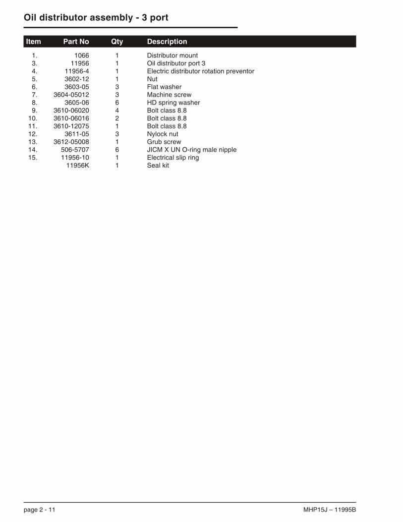
Item Part No Qty Description
1. 1066 1 Distributor mount3. 11956 1 Oil distributor port 34. 11956-4 1 Electric distributor rotation preventor5. 3602-12 1 Nut6. 3603-05 3 Flat washer7. 3604-05012 3 Machine screw8. 3605-06 6 HD spring washer9. 3610-06020 4 Bolt class 8.8
10. 3610-06016 2 Bolt class 8.811. 3610-12075 1 Bolt class 8.812. 3611-05 3 Nylock nut13. 3612-05008 1 Grub screw14. 506-5707 6 JICM X UN O-ring male nipple15. 11956-10 1 Electrical slip ring
11956K 1 Seal kit
page 2 - 11 MHP15J – 11995B
Oil distributor assembly - 3 port

MHP15J – 11995B page 2 - 12
Oil distributor assembly 3 port illustration
1
13
9
3
11
5
7
15
10
4
12
6
14
14
14
14
14
8
8
9
8
Oil distributor assembly 3 port illustration

Distributor 3 port
Item Part No Qty Description
1. 13-228 4 O-Ring Nitrile 90 DUR2. 3605-06 3 Spring washer3. 3610-06016 3 Metric bolt4. 11768-228 4 PTFE backup washer5. 11956-1 1 Distributor 3 part pillar6. 11956-2 1 Distributor barrel7. 11956-3 1 Distributor cap8. 11956-5 2 Wiper seal
11956K 1 Seal kit (includes items 1 & 4)
page 2 - 13 MHP15J – 11995B
Distributor 3 port
1
1
1
1
3
5
7
2
4
4
4
4
6
8
8

Section 3
Electrical schematic illustration . . . . . . . . . . . . . . . . 3-3
AC motor option wiring schematic illustration . . . . . 3-4
Road transport electric illustration. . . . . . . . . . . . . . 3-5
Upper control box assembly . . . . . . . . . . . . . . . . . . 3-6
Lower control box assembly . . . . . . . . . . . . . . . . . . 3-7
MHP15J – 11995B page 3 - 1
Section 3. - Electrical

page 3 - 2 MHP15J – 11995B

R1 = INTERLOCK RELAYR2 = IGNITION RELAYR3 = STABILISER RELAY
oP/N 1650-010oP/N 1650-010oP/N 1650-010
Note:(A1 - A12) and (B1 - B12) REPRESENT TERMINALS ON TERMINAL STRIP IN THE LOWER CONTROL BOX
B1
A5
EMERGSTOP
FOOTSW IGN
BATT ACC
START
LOWERBOOM
UPPERBOOM
JIBBOOM SLEW
BLEEDDOWN
B11SPEED
CONTROLRHEOSTAT
SPEEDCONTROLRHEOSTAT
PROPORTIONALCOILCONTROL
COIL DOWN DOWN
UPUP
EXT
RET
RIGHT
LEFTBLEEDDOWN
LIFTENABLELIGHT
LIFTENABLELIGHT
A8
HONDASTART
HOURMETER
R2 R2
87A
30 85
86
CHOKESOLENOID HONDA
COIL
A4CHOKE
B10
A7
R3R3
87A 87
A12
A11
A3
STABCOIL
STAB/BOOM
SW
A10
STABSW
A9
R185
86
A2
IGN
STARTBATT
EMERGSTOP
CIRCUITBREAKER
BATTERY
BOOMSW 2
30
87A87
P
G
GPLATFORM / GROUND
SELECTOR SWITCH.
LOWERBOOM
UPPERBOOM
JIBBOOM SLEW
A6
CHOKE
B12
85
86
30
A1
B4
B9
B8 B7
B6
B5
B4
B3
B2
LEFT
RIGHT
ROTATOROPTION
TITLE
Page 3 - 3
Electrical Schematic
Snorkel model MHP15JDWG. 0000000Rev. B 30-04-2004
BOOMSW 1
Electrical schematic illustration


MHP15J – 11995B page 3 - 4
AC motor option wiring schematic illustration
++
-
HONDASTARTERSOLENOID
A4R2(terminal 85)
YELL
OW
BRO
WN
GREEN
RED
A5
RELAY
4
1
3
5
8
6
7 2
CONTACTOR
0 1
2 4 6 8
M
ACMOTOR
PHASE
NEUTRAL
EARTH
POWER SUPPLY12v.DC
To B12
To A8
AC motor option wiring schematic illustration

page 3 - 5 MHP15J – 11995B
Road transport electric illustration
RIGHT TURN G (4)
LEFT TURN Y (1)
TAIL Br (7)
TAIL Br (7)
EARTH B (3)
EARTH B (3)
STOP R (6)
STOP R (6)
GG
Br
BrBr
Br
RR
R
BB
B NUMBER PLATE Br (7)Y
YTRAILER PLUG
PLUG AUSTRALIAREAR VIEW
Part Number 1286-001
Y(1)
R(6)
Br(7)5
G(4)
(2)
(3)B
PLUG NEW ZEALANDREAR VIEW
Part Number 1286-001
Y(1)
(2)
Br(7)
B(3)
G(4)
(6)R
(5)
WIRE CODE
3 B : BLACKBl : BLUE
6 R : RED1 Y : YELLOW
W : WHITE4 G : GREEN
P : PINK7 Br : BROWN
PLUG USAREAR VIEW
Part Number 1286-005
(GD) B
(LT)G
(RT)Y
(A)
R(S)
Br(TM)
PLUG EUROPEREAR VIEW
(1)G
(6)R
(7)B(5)BL
(4)Y
Br(3)
(2)
Road transport electric illustration

Upper control box assembly
Item Part No Qty Description
1. 11407-1 1 Control box, upper drilled2. 11420-1 1 Decal, control box, upper3. 302-0013 1 Switch, toggle SPST (On/Off)4. 302-0015 2 Switch, toggle SPST (Mom/Off)5. 302-0018 4 Switch, toggle DPDT (M/Off/M)
5A. 302-0018 1 Switch, toggle DPDT (M/Off/M) - Rotator option6. 302-0090 1 Keyswitch, anti restart7. 560377 1 Lamp, 12V green8. 304-0348 1 Knob, speed control switch9. 304-0412 1 Rheostat 25 ohm
10. 56223-6 1 Switch guard
MHP15J – 11995B page 3 - 6
Upper control box assembly
11420 - 1
LIFTENABLE
SPEED CONTROL
CHOKE
LOWEREMERGENCY
EMERGENCY LOWERTO LOWER PLATFORM, OPERATE EMERGENCY
LOWER SWITCH.
1.
2. TO SLEW BOOM, OPERATE ‘EMERGENCY
LOWER’ AND ‘SLEW’ SWITCHES TOGETHER
25
8
4
3
5
5
5
1
6
7
9
4
10
ROTATEPLATFORM
SLEW
UPPERBOOM
BOOMLOWER
JIBBOOM
5A

Lower control box assembly
Item Part No Qty Description
1. 11406-1 1 Control box, lower, drilled2. 11420 1 Decal, control box3. 302-0013 1 Switch, toggle SPST (On/Off)4. 302-0015 1 Switch, toggle SPST (Mom/Off)5. 302-0018 4 Switch, toggle DPDT (M/Off/M)6. 302-0048 1 Switch, toggle 4PDT (On/On)7. 3020087 1 Key switch8. 304-0348 1 Knob, speed control switch9. 304-0412 1 Rheostat 25 ohm
10. 455186 1 Hourmeter 12-60VDC square11. 560377 1 Lamp, 12V green12. 56223-6 1 Switch guard13. 56368-6 1 Circuit breaker 15 amp
page 3 - 7 MHP15J – 11995B
Lower control box assembly
LOWER
BOOMS
STABILISER
BASE
PLATFORM
CHOKE
11420
LIFTENABLE
7
5 11 2
3
125
5
5
1
13 10
15
8
9
4
6
3
UPPERBOOM
BOOM
JIBBOOM
Section 4
Rotator option . . . . . . . . . . . . . . . . . . . . . . . . . . . . . 4-2
Rotator option illustration. . . . . . . . . . . . . . . . . . . . . 4-3
MHP15J – 11995B page 4 - 1
Section 4. - Options
Rotator option
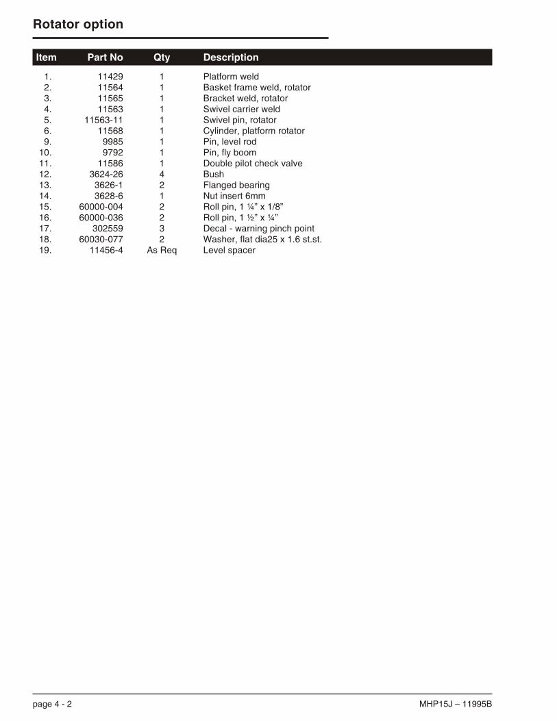
Item Part No Qty Description
1. 11429 1 Platform weld2. 11564 1 Basket frame weld, rotator3. 11565 1 Bracket weld, rotator4. 11563 1 Swivel carrier weld5. 11563-11 1 Swivel pin, rotator6. 11568 1 Cylinder, platform rotator9. 9985 1 Pin, level rod
10. 9792 1 Pin, fly boom11. 11586 1 Double pilot check valve12. 3624-26 4 Bush13. 3626-1 2 Flanged bearing14. 3628-6 1 Nut insert 6mm15. 60000-004 2 Roll pin, 1 ¼” x 1/8”16. 60000-036 2 Roll pin, 1 ½” x ¼”17. 302559 3 Decal - warning pinch point18. 60030-077 2 Washer, flat dia25 x 1.6 st.st.19. 11456-4 As Req Level spacer
page 4 - 2 MHP15J – 11995B
Rotator option

TITLE
Page 4 - 3
Rotator Option
Snorkel model MHP15JDWG. 11576
18
3
12
17
13
6
15
10
4
2
1
11
19
9
5
16
Rotator option illustration


Parts index - Page locator
A
Axle assembly, 1200kg, 1-12
B
Basket frame weld, 1-6Basket frame weld, rotator, 4-2Bracket weld, rotator, 4-2
C
Cylinder, flyboom, 2-8Cylinder, stabiliser, 2-9
D
Decals, 1-10
E
EngineCooling system, 2-3Displacement, 2-3Fuel, 2-3Fuel consumption, 2-3Fuel grade, 2-3Ignition system, 2-3Make, 2-3Model, 2-3Oil capacity, 2-3Oil grade, 2-3Type, 2-3
F
Foot switch, 1-6
H
Honda engine GX 160, 1-7
L
Lift cylinder, lower, 2-7Lift cylinder, upper, 2-6
M
Maintenance, 0-5Maintenance schedules, 0-6Manual organisation
See Maintenance information - page 3Manual Organization, 0-5Maximum height to basket floor, 2-3Maximum outreach, 2-3Maximum outreach height, 2-3Maximum towing speed, 2-3
O
Overall height, 2-3
P
Platform size, 2-3Platform weld, 1-6, 4-2Pump, 1-7
S
Safe working load, 2-3Standard colour, 2-3Swivel carrier weld, rotator, 4-2
T
Tail light, 1-6Trailer tongue weight, 2-3Travelling height, 2-3Turntable rotation, 2-3
W
Warranty - LimitedSee inside front cover
Working height, 2-3
MHP15J – 11995B index 1