Embed Size (px)
Citation preview
Upgrade and Maintenance Guide
Steelhead® EX (Series xx60) Steelhead® CX (Series xx55) Steelhead® (Series xx50)
Cascade® (Series xx60)
GraniteTM Core Appliance
Whitewater® Cloud Storage Appliance (Series xx10)
July 2013

© 2013 Riverbed Technology. All rights reserved.
Riverbed®, Cloud Steelhead®, Granite™, Interceptor®, RiOS®, Steelhead®, Think Fast®, Virtual Steelhead®, Whitewater®, Mazu®, Cascade®, Shark®, AirPcap®, BlockStream™, SkipWare®, TurboCap®, WinPcap®, Wireshark®, TrafficScript®, FlyScript™, WWOS™, and Stingray™ are trademarks or registered trademarks of Riverbed Technology, Inc. in the United States and other countries. Riverbed and any Riverbed product or service name or logo used herein are trademarks of Riverbed Technology. All other trademarks used herein belong to their respective owners. The trademarks and logos displayed herein cannot be used without the prior written consent of Riverbed Technology or their respective owners.
Akamai® and the Akamai wave logo are registered trademarks of Akamai Technologies, Inc. SureRoute is a service mark of Akamai. Apple and Mac are registered trademarks of Apple, Incorporated in the United States and in other countries. Cisco is a registered trademark of Cisco Systems, Inc. and its affiliates in the United States and in other countries. EMC, Symmetrix, and SRDF are registered trademarks of EMC Corporation and its affiliates in the United States and in other countries. IBM, iSeries, and AS/400 are registered trademarks of IBM Corporation and its affiliates in the United States and in other countries. Linux is a trademark of Linus Torvalds in the United States and in other countries. Microsoft, Windows, Vista, Outlook, and Internet Explorer are trademarks or registered trademarks of Microsoft Corporation in the United States and in other countries. Oracle and JInitiator are trademarks or registered trademarks of Oracle Corporation in the United States and in other countries. UNIX is a registered trademark in the United States and in other countries, exclusively licensed through X/Open Company, Ltd. VMware, ESX, ESXi are trademarks or registered trademarks of VMware, Incorporated in the United States and in other countries.
This product includes software developed by the University of California, Berkeley (and its contributors), EMC, and Comtech AHA Corporation. This product is derived from the RSA Data Security, Inc. MD5 Message-Digest Algorithm.
NetApp Manageability Software Development Kit (NM SDK), including any third-party software available for review with such SDK which can be found at http://communities.netapp.com/docs/DOC-1152, and are included in a NOTICES file included within the downloaded files.
For a list of open source software (including libraries) used in the development of this software along with associated copyright and license agreements, see the Riverbed Support site at https//support.riverbed.com.
This documentation is furnished “AS IS” and is subject to change without notice and should not be construed as a commitment by Riverbed Technology. This documentation may not be copied, modified or distributed without the express authorization of Riverbed Technology and may be used only in connection with Riverbed products and services. Use, duplication, reproduction, release, modification, disclosure or transfer of this documentation is restricted in accordance with the Federal Acquisition Regulations as applied to civilian agencies and the Defense Federal Acquisition Regulation Supplement as applied to military agencies. This documentation qualifies as “commercial computer software documentation” and any use by the government shall be governed solely by these terms. All other use is prohibited. Riverbed Technology assumes no responsibility or liability for any errors or inaccuracies that may appear in this documentation.
Riverbed Technology 199 Fremont StreetSan Francisco, CA 94105
Fax: 415.247.8801Web: http://www.riverbed.com
Phone: 415.247.8800
Part Number712-00016-18
Part Number712-00016-18
Contents
Preface.........................................................................................................................................................1
About This Guide ..........................................................................................................................................1Types of Users .........................................................................................................................................2Document Conventions .........................................................................................................................2
Electrostatic Discharge Guidelines..............................................................................................................2
Additional Resources ....................................................................................................................................2Release Notes ..........................................................................................................................................3Riverbed Documentation and the Support Knowledge Base ..........................................................3
Safety Guidelines ...........................................................................................................................................3
Contacting Riverbed......................................................................................................................................4Internet .....................................................................................................................................................4Technical Support ...................................................................................................................................4Professional Services ..............................................................................................................................4Documentation........................................................................................................................................4
Chapter 1 - Replacing Series xx55, xx60, and Granite Core Components............................................5
Before You Begin ............................................................................................................................................5Required Tools ........................................................................................................................................6
Opening the Bezel..........................................................................................................................................6
Removing the Chassis Cover .......................................................................................................................7Removing the Chassis Cover on the Desktop Models ......................................................................8Removing the Chassis Cover on the 1U Models................................................................................8Removing the Chassis Cover on the 2U Models................................................................................9
Replacing Disk Drives.................................................................................................................................10Replacing Disk Drives in 1U Series CX1555 and EX1160 ...............................................................10Replacing Disk Drives in 2U Series CX5055, CX7055, and EX1360...............................................12Replacing Disk Drives in 2U Series EX1260 and GC2000...............................................................14
Replacing Power Supply Units..................................................................................................................15Replacing Power Supply Units in 1U and 2U Appliances .............................................................15
Replacing Memory Modules......................................................................................................................16Replacing Memory Modules in Desktop Series CX555 and CX755 ..............................................17
Upgrade and Maintenance Guide iii
Contents
Replacing Memory Modules in 1U Series CX1555 and EX1160 ....................................................18Replacing Memory Modules in 2U Series CX5055, CX7055, EX1260, EX1360, and GC2000.....22
Replacing Fans .............................................................................................................................................26Determining Fan Status .......................................................................................................................26Replacing Fans in 1U Series CX1555 and EX1160 ............................................................................27Replacing Fans in 2U Series CX5055, CX7055, EX1260, EX1360, and GC2000 ............................28
Chapter 2 - Replacing Series xx50 Components...................................................................................31
Before You Begin ..........................................................................................................................................31
Replacing Disk Drives.................................................................................................................................32Replacing Disk Drives in Series 150, 250, and 550 Systems ...........................................................32Replacing Disk Drives in Series 1050 and 2050 Systems ................................................................34Replacing Disk Drives in Series 5050, 6050, IC 9350, and WWA xx10 Systems ..........................37Replacing Disk Drives in Series 7050L and 7050M Systems ..........................................................39
Replacing Power Supply Units ..................................................................................................................41Adding or Replacing Power Supply Units in Series 1050 and 2050 Systems ..............................41Replacing Power Supply Units in Series 5050, 6050, IC 9350, and WWA xx10 Systems............44
Replacing Memory ......................................................................................................................................45DIMM Slot Locations ...........................................................................................................................45Replacing Memory Modules in the 150, 250, and 550 Systems .....................................................47Replacing Memory Modules in 1U Series xx50 Systems ................................................................49Replacing Memory Modules in 3U Series xx50 Systems ................................................................51
Replacing Fans .............................................................................................................................................54Determining Fan Status .......................................................................................................................54Replacing Fans in Series 1050 and 2050 Systems .............................................................................55Replacing Fans in the Series 5050, 6050, 7050, IC 9350, and WWA xx10 Systems ......................59
Chapter 3 - Upgrading Series xx55, xx60, and GC2000 Systems ........................................................67
Overview.......................................................................................................................................................67Model Upgrades and Platform Requirements .................................................................................68Hardware Upgrade Kits ......................................................................................................................70Basic Steps..............................................................................................................................................70
Installing Licenses and Activating Specifications...................................................................................71Model Upgrades Using the CLI .........................................................................................................71Model Upgrades Using the Management Console .........................................................................73
Installing Hardware for Model Upgrades................................................................................................75Installing Required Memory and Disk Drives for CX755H Upgrades.........................................75Replacing Hard Disk Drives for CX1555H Upgrades .....................................................................77
Upgrading Memory for EX1260 Appliances ...........................................................................................79Upgrading to 32 GB..............................................................................................................................79Upgrading to 64 GB..............................................................................................................................79
Chapter 4 - Upgrading Series xx50 Systems .........................................................................................81
Overview.......................................................................................................................................................81
iv Upgrade and Maintenance Guide
Contents
Platform Requirements ........................................................................................................................82Upgrade Kit Hardware Contents .......................................................................................................84Hardware Requirements .....................................................................................................................85Basic Steps..............................................................................................................................................86
Installing Licenses and Activating Specifications...................................................................................86Model Upgrades Using the CLI .........................................................................................................87Model Upgrades Using the Management Console .........................................................................89
Installing Hardware for Basic Model Upgrades .....................................................................................91Installing Required Memory Modules for 1050L and 1050M to 1050H Upgrades .....................91Installing Required Hard Disk Drives for 1050L and 1050M to 1050H Upgrades......................93Installing Required Hard Disk Drives for 5050M to 5050H Upgrades.........................................93
Installing Hardware for RAID Model Upgrades ....................................................................................94Installing Required Memory Modules for 1050_LR and 1050_MR to 1050_HR Upgrades .......94Installing Required Hard Disk Drives for RAID Upgrades ...........................................................96
Chapter 5 - Restoring Series xx50 Systems from the Flash Drive.......................................................97
Identifying the System Hardware .............................................................................................................97
Restoring the Software Image on 3U Series xx50....................................................................................97
Restoring the Software Image on 1U Series xx50....................................................................................98
Upgrade and Maintenance Guide v

Contents
vi Upgrade and Maintenance Guide

Preface
Welcome to the Upgrade and Maintenance Guide. Read this preface for an overview of the information provided in this guide and for an understanding of the documentation conventions used throughout. This preface contains the following sections:
“About This Guide” on page 1
“Electrostatic Discharge Guidelines” on page 2
“Additional Resources” on page 2
“Safety Guidelines” on page 3
“Contacting Riverbed” on page 4
About This Guide
The Upgrade and Maintenance Guide describes how to replace and upgrade Riverbed system components.
Procedures and references to the 250, 550, 1050, and 2050 appliances apply to the Cloud Steelhead models CSH-250, CSH-550, CSH-1050, CSH-2050.
For detailed information about replacing system components in the Series EX560 or EX760 models, see the Series EX560 and EX760 Systems Owner’s Manual.
The CX255 models do not contain field replaceable components and are not included in this guide.
Procedures and references to the 6050 appliance apply to the Whitewater x10 and xx10 series appliances.
For information about the Whitewater xx30 appliances, see the Whitewater xx30 Series Hardware Owner’s Guide.
Procedures and references to the 1U and 2U xx60 models apply to the Cascade xx60 appliances and the Cascade Shark 1100, 2100, and 2200.
Important: RiOS v7.0.1 or later is not supported on the Series xx20 hardware platforms. For detailed information about the Series xx20 hardware platforms, see the documentation set for RiOS v6.5 or earlier.
Upgrade and Maintenance Guide 1

Preface Electrostatic Discharge Guidelines
Types of Users
This guide is written for storage and network administrators managing networks with Riverbed products.
Document Conventions
This manual uses the following standard set of typographical conventions to introduce new terms, illustrate screen displays, describe command syntax, and so forth.
Electrostatic Discharge Guidelines
Follow these ESD guidelines to ensure that your equipment is not damaged from improper handling:
When you install or perform maintenance tasks, you must wear a grounded ESD anti-static strap to protect the system hardware against electrostatic discharge. Make sure that the strap makes skin contact prior to handling equipment.
Periodically check the resistance value of the anti-static strap to ensure it is functioning properly.
If you remove or replace system components, you must transport the unit in a conductive container or an ESD bag that has been grounded or neutralized.
Store any system components in their protective packaging until you are ready to install them.
Do not touch the electronic components on system hardware.
Additional Resources
This section describes resources that supplement the information in this guide. It contains the following sections:
“Release Notes” on page 3
“Riverbed Documentation and the Support Knowledge Base” on page 3
Convention Meaning
italics Within text, new terms and emphasized words appear in italic typeface.
boldface Within text, CLI commands and GUI controls appear in bold typeface.
Courier Code examples appear in Courier font:
amnesiac > enableamnesiac # configure terminal
2 Upgrade and Maintenance Guide
Safety Guidelines Preface
Release Notes
The online software release notes supplement the information in this manual. The release notes are available in the Software section of the Riverbed Support site at https://support.riverbed.com.
The following table describes the release notes.
Examine the online release notes before you begin the installation and configuration process. They contain important information about this release of the Steelhead appliance.
Riverbed Documentation and the Support Knowledge Base
For a complete list and the most current version of Riverbed documentation, log in to the Riverbed Support site at https://support.riverbed.com.
The Riverbed Knowledge Base is a database of known issues, how-to documents, system requirements, and common error messages. You can browse titles or search for keywords and strings.
To access the Riverbed Knowledge Base, log in to the Riverbed Support site athttps://support.riverbed.com.
Safety Guidelines
Follow the safety precautions outlined in the Safety and Compliance Guide when installing and setting up your equipment.
Important: Failure to follow these safety guidelines can result in injury or damage to the equipment. Mishandling of the equipment voids all warranties. Read and follow safety guidelines and installation instructions carefully.
Many countries require the safety information to be presented in their national languages. If this requirement applies to your country, consult the Safety and Compliance Guide. Before you install, operate, or service the Riverbed products, you must be familiar with the safety information. Refer to the Safety and Compliance Guide if you do not clearly understand the safety information provided in the product documentation.
Online File Format Purpose
<product>_<version_number><build_number>.pdf
Describes the product release and identifies fixed problems, known problems, and work-arounds. This file also provides documentation information not covered in the guides or that has been modified since publication.
Upgrade and Maintenance Guide 3
Preface Contacting Riverbed
Contacting Riverbed
This section describes how to contact departments within Riverbed.
Internet
You can learn about Riverbed products through our Web site at http://www.riverbed.com.
Technical Support
If you have problems installing, using, or replacing Riverbed products, contact Riverbed Support or your channel partner who provides support. To contact Riverbed Support, open a trouble ticket by calling 1-888-RVBD-TAC (1-888-782-3822) in the United States and Canada or +1 415 247 7381 outside the United States. You can also go to https://support.riverbed.com.
Professional Services
Riverbed has a staff of professionals who can help you with installation, provisioning, network redesign, project management, custom designs, consolidation project design, and custom coded solutions. To contact Riverbed Professional Services, email [email protected] or go to http://www.riverbed.com/us/products/professional_services/.
Documentation
The Riverbed Technical Publications team continually strives to improve the quality and usability of Riverbed documentation. Riverbed appreciates any suggestions you might have about its online documentation or printed materials. Send documentation comments to [email protected].
4 Upgrade and Maintenance Guide

CHAPTER 1 Replacing Series xx55, xx60, and Granite Core Components
This chapter describes how to replace hardware components in desktop Series CX555 and CX755, 1U Series CX1555 and EX1160, 2U Series CX5055, CX7055, EX1260, EX1360, and Granite Core (GC2000) systems.
This chapter includes the following sections:
“Before You Begin” on page 5
“Opening the Bezel” on page 6
“Removing the Chassis Cover” on page 7
“Replacing Disk Drives” on page 10
“Replacing Power Supply Units” on page 15
“Replacing Memory Modules” on page 16
“Replacing Fans” on page 26
Important: For detailed information about replacing system components in the Series EX560 or EX760 models, see the Series EX560 and EX760 Systems Owner’s Manual.
Note: The CX255 models do not contain field replaceable components and are not included in this guide.
Before You Begin
These instructions are applicable to the following Riverbed products:
Steelhead CX (v7.0.1 or later), Steelhead EX (v1.0.0 or later)
Granite Core (v1.0 or later)
Cascade Profiler, Sensor, Express, Gateway (v9.1 or later)
Cascade Shark
Upgrade and Maintenance Guide 5

Replacing Series xx55, xx60, and Granite Core Components Opening the Bezel
Required Tools
You need the following tools and equipment to replace system components:
You must use approved components for the system to function properly. Installation of unapproved system components will result in boot failure. To order system components, contact Riverbed Support at https://support.riverbed.com.
An anti-static strap. When you replace system components you must wear a grounded ESD anti-static strap to protect the system hardware against electrostatic discharge. Make sure that the strap makes skin contact prior to handling equipment.
Use the magnetic Phillips screwdriver enclosed with your shipment to remove screws in the system. The magnetic screwdriver ensures screws are not lost in the system.
Opening the Bezel
The following procedure describes how to open the front bezel on xx55, xx60, and GC2000 systems.
To release the bezel, press the tabs on each side of the bezel and pull toward you. The bezel remains attached to the system on hinges.
Figure 1-1. Opening the Bezel on 1U and 2U Series xx55, xx60, and GC2000 Systems
6 Upgrade and Maintenance Guide

Removing the Chassis Cover Replacing Series xx55, xx60, and Granite Core Components
Figure 1-2. Opening the Bezel on 2U Series xx55 and xx60 Systems with 2.5-Inch Drives
Removing the Chassis Cover
This section describes how to remove the chassis cover on x55, xx60, and Granite Core systems. It includes the following sections:
“Removing the Chassis Cover on the Desktop Models” on page 8, including the CX555 and CX755 appliances.
“Removing the Chassis Cover on the 1U Models” on page 8, including the CX1555 and EX1160 appliances
“Removing the Chassis Cover on the 2U Models” on page 9, including the CX5055, CX7055, EX1260, EX1360, and GC2000 appliances.
Upgrade and Maintenance Guide 7

Replacing Series xx55, xx60, and Granite Core Components Removing the Chassis Cover
Removing the Chassis Cover on the Desktop Models
This section describes how to remove the chassis covers for the CX555 and CX755 appliances.
To remove the chassis cover on Desktop Series CX555 and CX755 systems
1. With the included screwdriver, remove the two screws on the back of the chassis cover.
Figure 1-3. Removing the Locking Screws
2. Position your thumbs on the top of the appliance and slide the cover back from the chassis.
Removing the Chassis Cover on the 1U Models
This section describes how to remove the chassis covers for the CX1555 and EX1160 appliances.
To remove the chassis cover on 1U Series CX1555 and EX1160 Systems
1. Unscrew the two locking screws on the back of the chassis.
Figure 1-4. Unscrewing the Locking Screws
2. Unscrew and remove a third locking screw on the left side near the back of the top cover.
8 Upgrade and Maintenance Guide
Removing the Chassis Cover Replacing Series xx55, xx60, and Granite Core Components
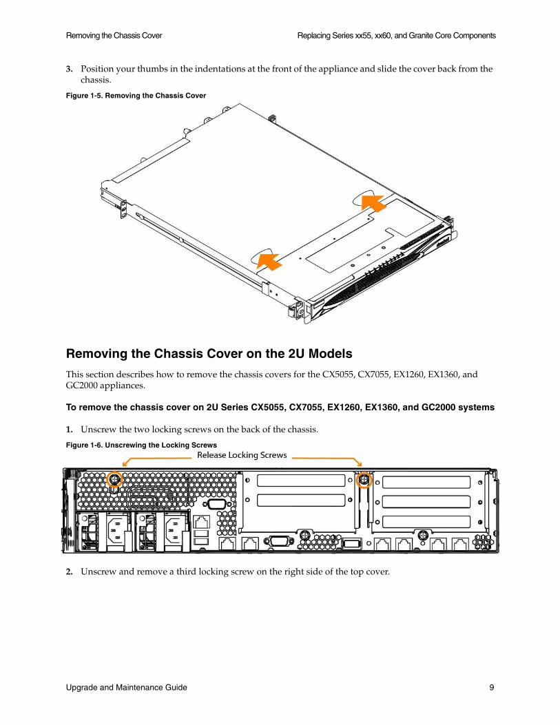
3. Position your thumbs in the indentations at the front of the appliance and slide the cover back from the chassis.
Figure 1-5. Removing the Chassis Cover
Removing the Chassis Cover on the 2U Models
This section describes how to remove the chassis covers for the CX5055, CX7055, EX1260, EX1360, and GC2000 appliances.
To remove the chassis cover on 2U Series CX5055, CX7055, EX1260, EX1360, and GC2000 systems
1. Unscrew the two locking screws on the back of the chassis.
Figure 1-6. Unscrewing the Locking Screws
2. Unscrew and remove a third locking screw on the right side of the top cover.
Upgrade and Maintenance Guide 9

Replacing Series xx55, xx60, and Granite Core Components Replacing Disk Drives
3. Position your thumbs in the indentations at the front of the appliance and slide the cover back from the chassis.
Figure 1-7. Removing the Chassis Cover
Replacing Disk Drives
The following section describes how to remove and replace disk drives in the CX, EX, and Granite systems.
This section includes the following procedures:
“Replacing Disk Drives in 1U Series CX1555 and EX1160” on page 10
“Replacing Disk Drives in 2U Series CX5055, CX7055, and EX1360” on page 12
“Replacing Disk Drives in 2U Series EX1260 and GC2000” on page 14
Note: If you need to replace an appliance, you cannot move the disks to preserve your data. Each disk is encoded with machine-level information and moving disks is not supported.
Replacing Disk Drives in 1U Series CX1555 and EX1160
Series CX1555 and EX1160 systems are equipped with replaceable, hot-swappable hard-disk drives (HDD) and solid-state drives (SSD).
10 Upgrade and Maintenance Guide
Replacing Disk Drives Replacing Series xx55, xx60, and Granite Core Components
You must use approved disk drives. To order disk drives, contact Riverbed Support at https://support.riverbed.com.
Important: When you replace disk drives, you must wear a grounded ESD anti-static strap to protect the system hardware against electrostatic discharge. Make sure that the strap makes skin contact prior to handling equipment.
Caution: Use caution when you remove or replace system components; they can become hot to the touch.
To replace the disk drive in the 1U Series xx55 and xx60 systems
1. Open the bezel.
See “Opening the Bezel” on page 6.
2. Identify the faulty disk drive.
The Alarm Status page in the Management Console identifies the faulty disk drive.
The disk drive LED is orange for failed drives.
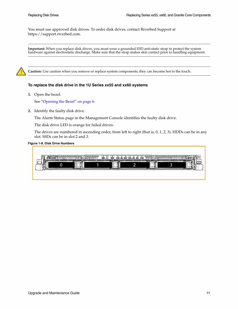
The drives are numbered in ascending order, from left to right (that is, 0, 1, 2, 3). HDDs can be in any slot. SSDs can be in slot 2 and 3.
Figure 1-8. Disk Drive Numbers
Upgrade and Maintenance Guide 11
Replacing Series xx55, xx60, and Granite Core Components Replacing Disk Drives
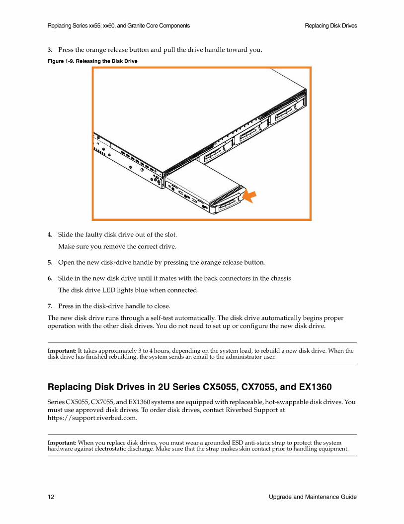
3. Press the orange release button and pull the drive handle toward you.
Figure 1-9. Releasing the Disk Drive
4. Slide the faulty disk drive out of the slot.
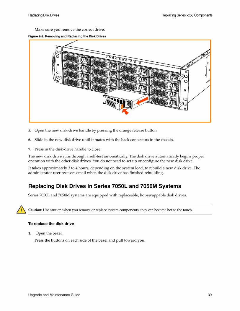
Make sure you remove the correct drive.
5. Open the new disk-drive handle by pressing the orange release button.
6. Slide in the new disk drive until it mates with the back connectors in the chassis.
The disk drive LED lights blue when connected.
7. Press in the disk-drive handle to close.
The new disk drive runs through a self-test automatically. The disk drive automatically begins proper operation with the other disk drives. You do not need to set up or configure the new disk drive.
Important: It takes approximately 3 to 4 hours, depending on the system load, to rebuild a new disk drive. When the disk drive has finished rebuilding, the system sends an email to the administrator user.
Replacing Disk Drives in 2U Series CX5055, CX7055, and EX1360
Series CX5055, CX7055, and EX1360 systems are equipped with replaceable, hot-swappable disk drives. You must use approved disk drives. To order disk drives, contact Riverbed Support at https://support.riverbed.com.
Important: When you replace disk drives, you must wear a grounded ESD anti-static strap to protect the system hardware against electrostatic discharge. Make sure that the strap makes skin contact prior to handling equipment.
12 Upgrade and Maintenance Guide
Replacing Disk Drives Replacing Series xx55, xx60, and Granite Core Components
Caution: Use caution when you remove or replace system components; they can become hot to the touch.
To replace a 2.5-inch disk drive in the 2U Series xx55 and xx60 systems
1. Open the bezel.
See “Opening the Bezel” on page 6.
2. Identify the faulty disk drive.
The Alarm Status page in the Management Console identifies the faulty disk drive.
The disk drive LED is orange for failed drives.
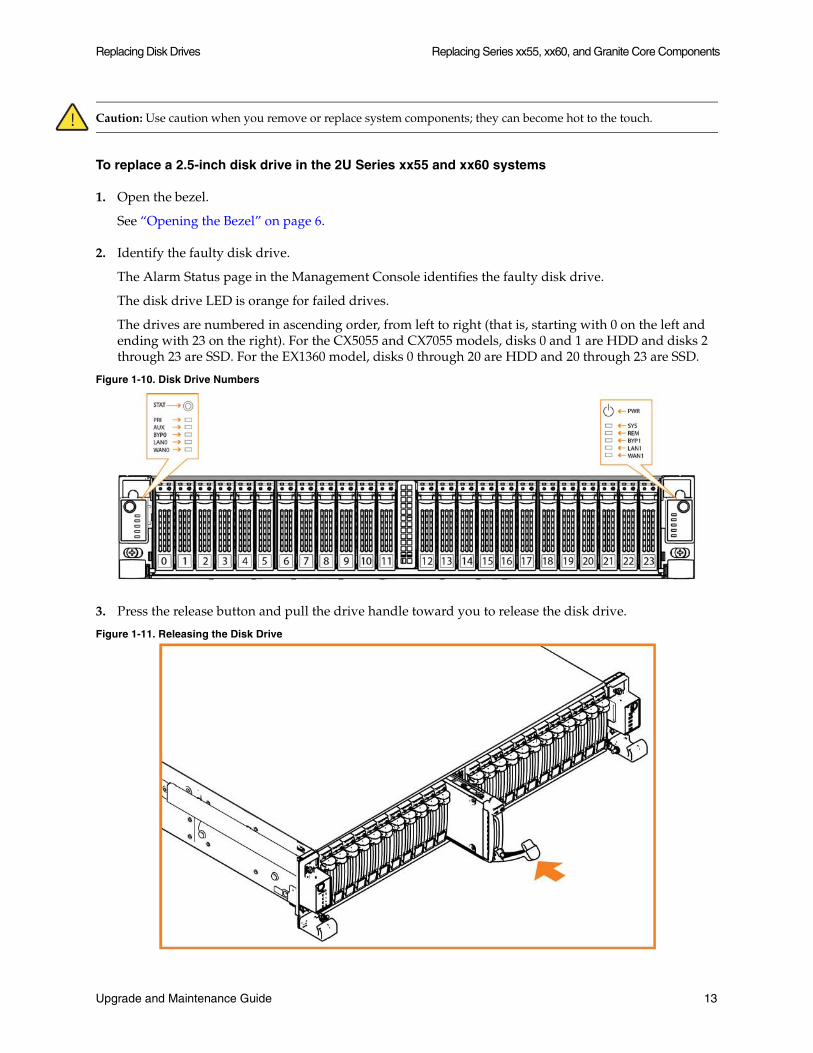
The drives are numbered in ascending order, from left to right (that is, starting with 0 on the left and ending with 23 on the right). For the CX5055 and CX7055 models, disks 0 and 1 are HDD and disks 2 through 23 are SSD. For the EX1360 model, disks 0 through 20 are HDD and 20 through 23 are SSD.
Figure 1-10. Disk Drive Numbers
3. Press the release button and pull the drive handle toward you to release the disk drive.
Figure 1-11. Releasing the Disk Drive
Upgrade and Maintenance Guide 13

Replacing Series xx55, xx60, and Granite Core Components Replacing Disk Drives
4. Slide the faulty disk drive out of the slot.
Make sure you remove the correct drive.
5. Open the new disk-drive handle by pressing the release button.
6. Slide in the new disk drive until it mates with the back connectors in the chassis.
The disk drive LED lights blue when connected.
7. Press in the disk-drive handle to close.
The new disk drive runs through a self-test automatically. The disk drive automatically begins proper operation with the other disk drives. You do not need to set up or configure the new disk drive.
Replacing Disk Drives in 2U Series EX1260 and GC2000
Series EX1260 and GC2000 systems are equipped with replaceable, hot-swappable disk drives. You must use approved disk drives. To order disk drives, contact Riverbed Support at https://support.riverbed.com.
Important: When you replace disk drives, you must wear a grounded ESD anti-static strap to protect the system hardware against electrostatic discharge. Make sure that the strap makes skin contact prior to handling equipment.
Caution: Use caution when you remove or replace system components; they can become hot to the touch.
To replace a disk drive in the 2U Series xx60 and GC2000 systems
1. Open the bezel.
See “Opening the Bezel” on page 6.
2. Identify the faulty disk drive.
The Alarm Status page in the Management Console identifies the faulty disk drive.
The disk drive LED is orange for failed drives.
The drives are numbered in ascending order, from the upper-left corner to the lower-right corner. HDDs can be in any slot. SSDs can be in slots 8 through 11.
Figure 1-12. Disk Drive Numbers
14 Upgrade and Maintenance Guide

Replacing Power Supply Units Replacing Series xx55, xx60, and Granite Core Components
3. Press the orange release button and pull the drive handle toward you to release the disk drive.
Figure 1-13. Releasing the Disk Drive
4. Slide the faulty disk drive out of the slot.
Make sure you remove the correct drive.
5. Open the new disk-drive handle by pressing the orange release button.
6. Slide in the new disk drive until it mates with the back connectors in the chassis.
The disk drive LED lights blue when connected.
7. Press in the disk-drive handle to close.
The new disk drive runs through a self-test automatically. The disk drive automatically begins proper operation with the other disk drives. You do not need to set up or configure the new disk drive.
Replacing Power Supply Units
The following section describes how to remove and replace a power supply unit in CX, EX, and Granite appliances.
Replacing Power Supply Units in 1U and 2U Appliances
This section describes how to replace a power supply in 1U Series CX1555 and EX1160 and 2U Series CX5055, CX7055, EX1260, EX1360, and GC2000 systems. These systems are equipped with replaceable, hot-swappable power supply units.
Upgrade and Maintenance Guide 15

Replacing Series xx55, xx60, and Granite Core Components Replacing Memory Modules
Caution: Use gloves when replacing the power supply units; they can become hot to the touch.
To replace power supply units in 1U and 2U Series xx55, xx60, and GC2000 systems
1. Locate the defective power supply unit and remove the power cord.
2. Press the release tab toward the black handle, and pull the power supply unit toward you.
Figure 1-14. Removing the Power Supply Unit from 1U and 2U Series xx55, xx60, and GC2000 Systems
Power Supply 0 (PS0) is on the left and Power Supply 1 (PS1) is on the right.
3. Pull the power supply unit out of the chassis.
Caution: Put the defective power supply unit aside; wait until it cools down before touching it.
4. Slide in the new power supply unit until it mates with the back connectors in the chassis.
When the power supply unit is pushed all the way in, the button clicks to the right.
5. Plug the AC power cord into the new power supply unit.
Replacing Memory Modules
The following section describes how to remove and replace memory modules in the x55, xx55, and xx60 series systems. This section includes the following procedures:
“Replacing Memory Modules in Desktop Series CX555 and CX755” on page 17
“Replacing Memory Modules in 1U Series CX1555 and EX1160” on page 18
16 Upgrade and Maintenance Guide
Replacing Memory Modules Replacing Series xx55, xx60, and Granite Core Components
“Replacing Memory Modules in 2U Series CX5055, CX7055, EX1260, EX1360, and GC2000” on page 22
Replacing Memory Modules in Desktop Series CX555 and CX755
The following section describes how to replace memory modules in Desktop Series CX555 and CX755 systems.
Important: You must use approved memory modules. Contact Riverbed Support at https://support.riverbed.com to obtain the correct memory modules.
To replace the memory modules in the Desktop Series x55 systems
1. Power down the system.
2. Disconnect the system from the electrical outlet and peripherals.
3. Remove the chassis cover.
See “Removing the Chassis Cover on the Desktop Models” on page 8.
Caution: Be careful not to touch the adjacent power supply unit. Touching the power supply unit could cause electric shock.
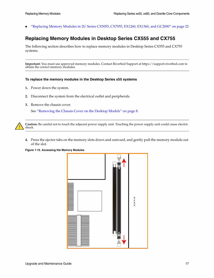
4. Press the ejector tabs on the memory slots down and outward, and gently pull the memory module out of the slot.
Figure 1-15. Accessing the Memory Modules
Upgrade and Maintenance Guide 17
Replacing Series xx55, xx60, and Granite Core Components Replacing Memory Modules
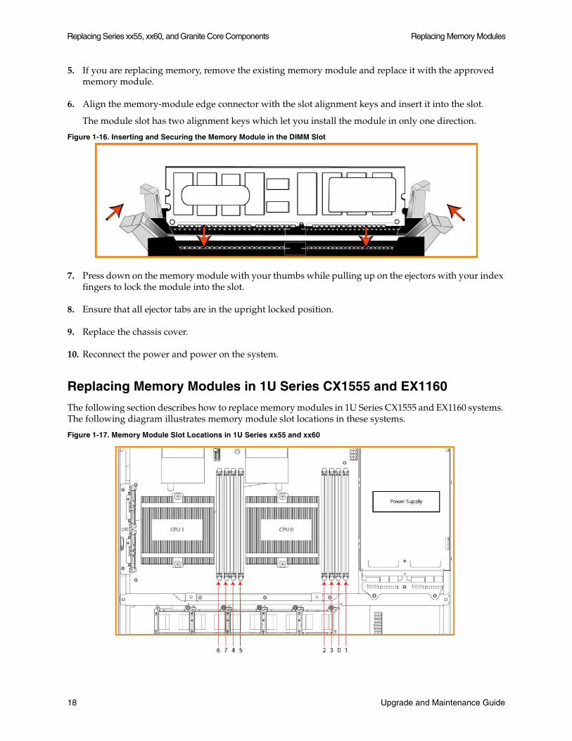
5. If you are replacing memory, remove the existing memory module and replace it with the approved memory module.
6. Align the memory-module edge connector with the slot alignment keys and insert it into the slot.
The module slot has two alignment keys which let you install the module in only one direction.
Figure 1-16. Inserting and Securing the Memory Module in the DIMM Slot
7. Press down on the memory module with your thumbs while pulling up on the ejectors with your index fingers to lock the module into the slot.
8. Ensure that all ejector tabs are in the upright locked position.
9. Replace the chassis cover.
10. Reconnect the power and power on the system.
Replacing Memory Modules in 1U Series CX1555 and EX1160
The following section describes how to replace memory modules in 1U Series CX1555 and EX1160 systems. The following diagram illustrates memory module slot locations in these systems.
Figure 1-17. Memory Module Slot Locations in 1U Series xx55 and xx60
18 Upgrade and Maintenance Guide

Replacing Memory Modules Replacing Series xx55, xx60, and Granite Core Components
When adding new memory to the 1U xx55 and xx60 appliances, add the memory in the black slots first. Once the black slots are full, populate the blue slots. Make sure the memory is equally distributed on both sides.
To replace the memory modules in the 1U Series CX1555 and EX1160 systems
1. Power down the system.
2. Remove the chassis cover.
See “To remove the chassis cover on 1U Series CX1555 and EX1160 Systems” on page 8.
3. To access CPU 1 memory modules, you must remove the PCIe enclosure. Remove the retaining screws of the PCIe enclosure on the back of the system.
Figure 1-18. Removing PCIe Enclosure Locking Screws
Upgrade and Maintenance Guide 19
Replacing Series xx55, xx60, and Granite Core Components Replacing Memory Modules
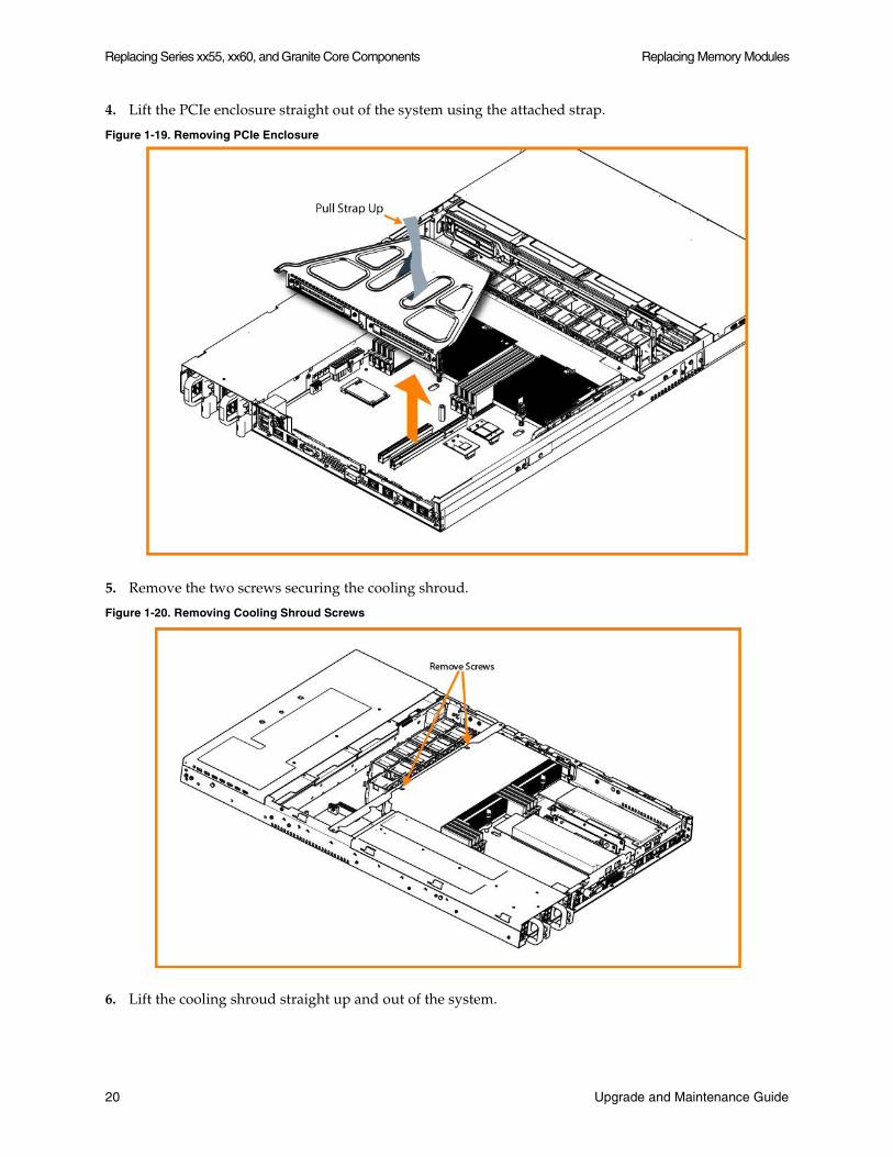
4. Lift the PCIe enclosure straight out of the system using the attached strap.
Figure 1-19. Removing PCIe Enclosure
5. Remove the two screws securing the cooling shroud.
Figure 1-20. Removing Cooling Shroud Screws
6. Lift the cooling shroud straight up and out of the system.
20 Upgrade and Maintenance Guide

Replacing Memory Modules Replacing Series xx55, xx60, and Granite Core Components
Caution: Lift the shroud straight up to avoid damaging any components of the system.
7. Press the ejector tabs on the memory slots down and outward, and gently pull the memory module out of the slot.
Figure 1-21. Accessing the Memory Modules
8. Remove the existing memory module and replace it with an approved memory module of the same size.
Important: Replacing the existing memory module with a module of a different size causes the system to fail. You must use approved memory modules. Contact Riverbed Support at https://support.riverbed.com to obtain the correct memory modules.
9. Align the memory-module edge connector with the slot alignment keys and insert it into the slot.
The module slot has two alignment keys that allow you to install the module in only one direction.
Figure 1-22. Inserting the Memory Modules into the Connector Slot and Securing
10. Press down on the memory module with your thumbs while pulling up on the ejectors with your index fingers to lock the module into the slot.
11. Ensure that all ejector tabs are in the upright locked position.
Upgrade and Maintenance Guide 21

Replacing Series xx55, xx60, and Granite Core Components Replacing Memory Modules
12. If necessary, replace the PCIe enclosure.
13. Replace the cooling shroud.
14. Replace the chassis cover.
15. Replace the power cords and peripherals.
16. Power on the system.
Replacing Memory Modules in 2U Series CX5055, CX7055, EX1260, EX1360, and GC2000
The following section describes how to replace memory modules in the 2U Series CX5055, CX7055, EX1260, EX1360, and GC2000 systems.
The following diagram illustrates memory module slot locations in these systems.
Figure 1-23. Memory Module Slot Locations in 2U Series xx55 and xx60
When adding new memory to the 2U xx55 and xx60 appliances, add the memory in the black slots first. Once the black slots are full, populate the blue slots. Make sure the memory is equally distributed on both sides.
To replace memory modules in the 2U Series xx55 and xx60 systems
1. Power down the system.
2. Open the chassis cover.
See “To remove the chassis cover on 2U Series CX5055, CX7055, EX1260, EX1360, and GC2000 systems” on page 9.
22 Upgrade and Maintenance Guide

Replacing Memory Modules Replacing Series xx55, xx60, and Granite Core Components
3. To release the PCIe enclosure, remove the two retaining screws on the top of the enclosure and the two retaining screws on the rear panel.
Figure 1-24. Removing PCIe Enclosures
Upgrade and Maintenance Guide 23

Replacing Series xx55, xx60, and Granite Core Components Replacing Memory Modules
4. To remove the right and left PCIe enclosure from the chassis, place your fingers in the enclosure holes and lift straight up.
Figure 1-25. Removing the PCIe Enclosures from the Chassis
5. Remove the screws securing the cooling shroud to access the memory module slots.
Figure 1-26. Removing Cooling Shroud
Caution: Be careful not to damage any surrounding components when removing and installing the cooling shroud. Lift the shroud straight up to avoid damaging any components of the system.
24 Upgrade and Maintenance Guide
Replacing Memory Modules Replacing Series xx55, xx60, and Granite Core Components
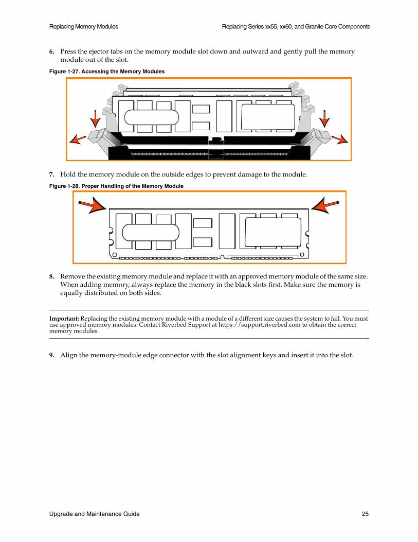
6. Press the ejector tabs on the memory module slot down and outward and gently pull the memory module out of the slot.
Figure 1-27. Accessing the Memory Modules
7. Hold the memory module on the outside edges to prevent damage to the module.
Figure 1-28. Proper Handling of the Memory Module
8. Remove the existing memory module and replace it with an approved memory module of the same size. When adding memory, always replace the memory in the black slots first. Make sure the memory is equally distributed on both sides.
Important: Replacing the existing memory module with a module of a different size causes the system to fail. You must use approved memory modules. Contact Riverbed Support at https://support.riverbed.com to obtain the correct memory modules.
9. Align the memory-module edge connector with the slot alignment keys and insert it into the slot.
Upgrade and Maintenance Guide 25
Replacing Series xx55, xx60, and Granite Core Components Replacing Fans
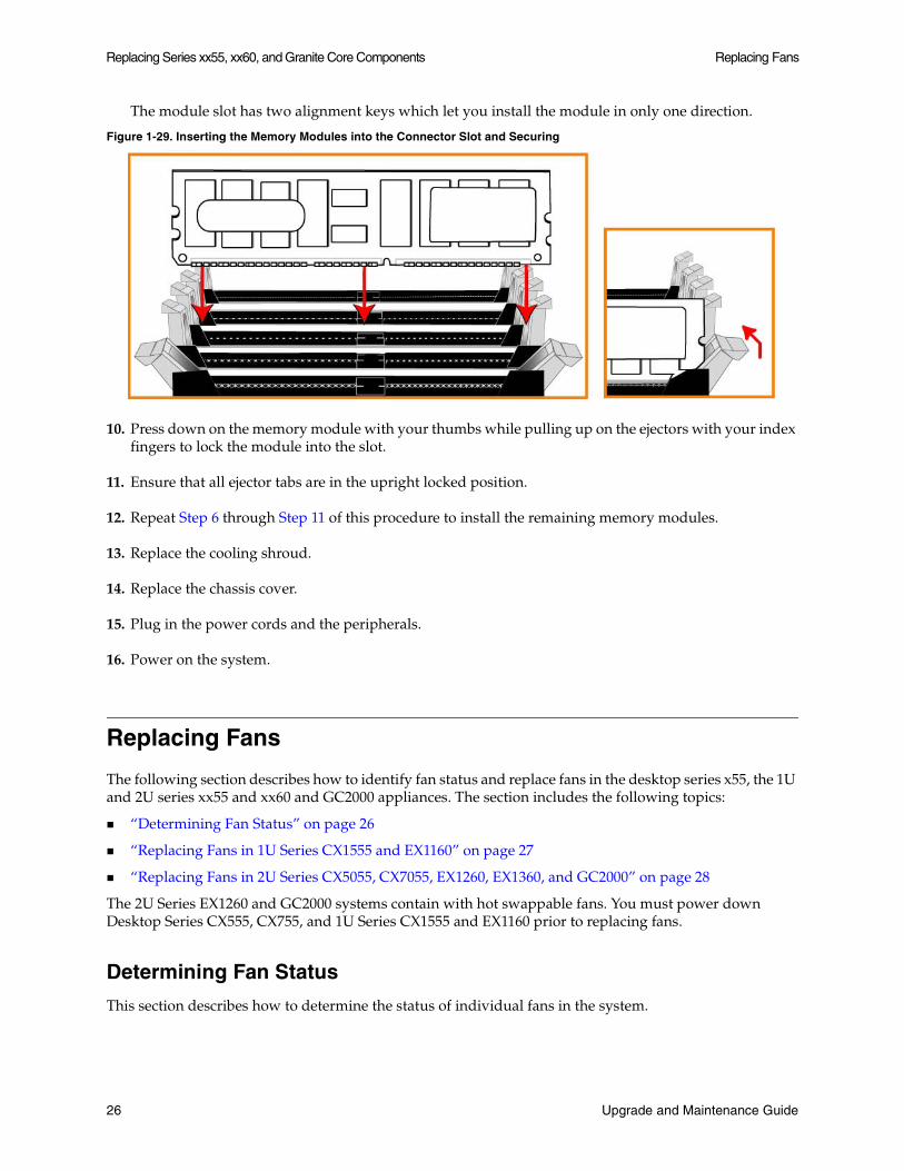
The module slot has two alignment keys which let you install the module in only one direction.
Figure 1-29. Inserting the Memory Modules into the Connector Slot and Securing
10. Press down on the memory module with your thumbs while pulling up on the ejectors with your index fingers to lock the module into the slot.
11. Ensure that all ejector tabs are in the upright locked position.
12. Repeat Step 6 through Step 11 of this procedure to install the remaining memory modules.
13. Replace the cooling shroud.
14. Replace the chassis cover.
15. Plug in the power cords and the peripherals.
16. Power on the system.
Replacing Fans
The following section describes how to identify fan status and replace fans in the desktop series x55, the 1U and 2U series xx55 and xx60 and GC2000 appliances. The section includes the following topics:
“Determining Fan Status” on page 26
“Replacing Fans in 1U Series CX1555 and EX1160” on page 27
“Replacing Fans in 2U Series CX5055, CX7055, EX1260, EX1360, and GC2000” on page 28
The 2U Series EX1260 and GC2000 systems contain with hot swappable fans. You must power down Desktop Series CX555, CX755, and 1U Series CX1555 and EX1160 prior to replacing fans.
Determining Fan Status
This section describes how to determine the status of individual fans in the system.
26 Upgrade and Maintenance Guide

Replacing Fans Replacing Series xx55, xx60, and Granite Core Components
To determine fan status
1. Connect to the CLI.
For details, see the Riverbed Command-Line Interface Reference Manual.
2. At the system prompt enter the show stats fan command.
amnesiac> show stats fanFanId RPM Min RPM Status0 4963 1080 ok1 4963 1080 ok2 4821 1080 ok3 4963 1080 ok4 4963 1080 ok5 4821 1080 ok
The output and number of fans vary depending on your system model.
Replacing Fans in 1U Series CX1555 and EX1160
This section describes how to replace fans in the 1U Series CX1555 and EX1160 systems. These models are equipped with five fans in a single casing. The fans are not hot-swappable; you must power down the system before replacing the fans.
Important: You must use approved fans. To order fans, contact Riverbed Support at https://support.riverbed.com.
To replace the fans in the 1U Series CX1555 and EX1160 systems
1. Remove the chassis cover.
See “To remove the chassis cover on 1U Series CX1555 and EX1160 Systems” on page 8.
2. Unplug the fan cables from the cable jacks on the motherboard.
Upgrade and Maintenance Guide 27
Replacing Series xx55, xx60, and Granite Core Components Replacing Fans
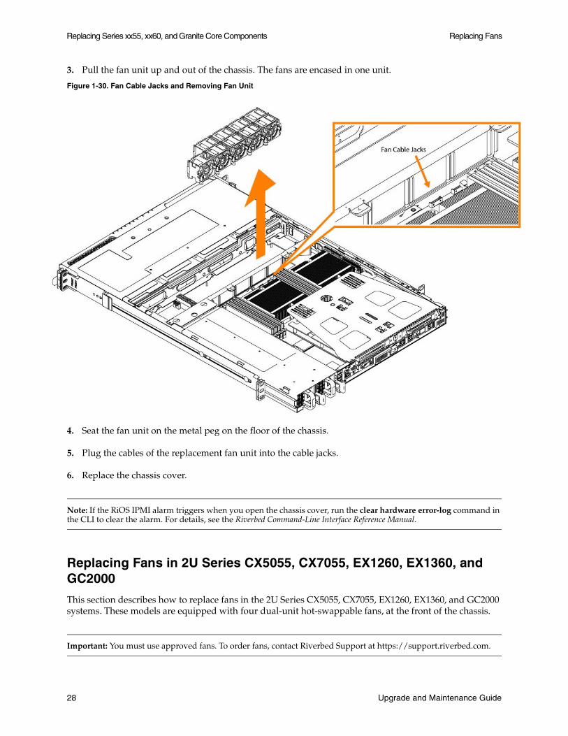
3. Pull the fan unit up and out of the chassis. The fans are encased in one unit.
Figure 1-30. Fan Cable Jacks and Removing Fan Unit
4. Seat the fan unit on the metal peg on the floor of the chassis.
5. Plug the cables of the replacement fan unit into the cable jacks.
6. Replace the chassis cover.
Note: If the RiOS IPMI alarm triggers when you open the chassis cover, run the clear hardware error-log command in the CLI to clear the alarm. For details, see the Riverbed Command-Line Interface Reference Manual.
Replacing Fans in 2U Series CX5055, CX7055, EX1260, EX1360, and GC2000
This section describes how to replace fans in the 2U Series CX5055, CX7055, EX1260, EX1360, and GC2000 systems. These models are equipped with four dual-unit hot-swappable fans, at the front of the chassis.
Important: You must use approved fans. To order fans, contact Riverbed Support at https://support.riverbed.com.
28 Upgrade and Maintenance Guide
Replacing Fans Replacing Series xx55, xx60, and Granite Core Components
To replace the fans in the 2U Series systems
1. Remove the chassis cover.
See “To remove the chassis cover on 2U Series CX5055, CX7055, EX1260, EX1360, and GC2000 systems” on page 9.
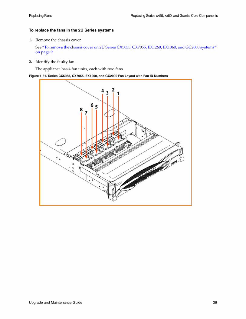
2. Identify the faulty fan.
The appliance has 4 fan units, each with two fans.
Figure 1-31. Series CX5055, CX7055, EX1260, and GC2000 Fan Layout with Fan ID Numbers
Upgrade and Maintenance Guide 29
Replacing Series xx55, xx60, and Granite Core Components Replacing Fans
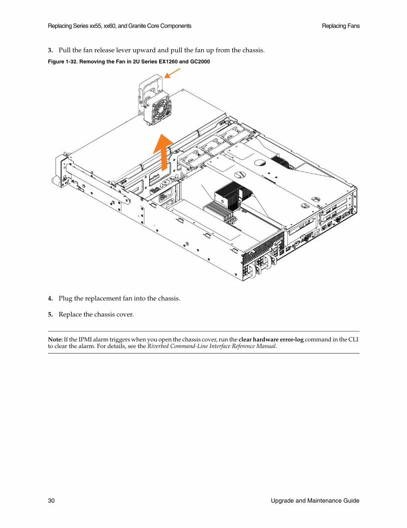
3. Pull the fan release lever upward and pull the fan up from the chassis.
Figure 1-32. Removing the Fan in 2U Series EX1260 and GC2000
4. Plug the replacement fan into the chassis.
5. Replace the chassis cover.
Note: If the IPMI alarm triggers when you open the chassis cover, run the clear hardware error-log command in the CLI to clear the alarm. For details, see the Riverbed Command-Line Interface Reference Manual.
30 Upgrade and Maintenance Guide
CHAPTER 2 Replacing Series xx50 Components
This chapter describes how to replace Series xx50 system components. It includes the following sections:
“Before You Begin” on page 31
“Replacing Disk Drives” on page 32
“Replacing Power Supply Units” on page 41
“Replacing Memory” on page 45
“Replacing Fans” on page 54
To access instructional videos describing how to identify specific Steelhead appliance models as well as how to replace disk drives for each model family, go to https://support.riverbed.com/kb/multimedia.htm.
Important: You must use approved components for the system to function properly. Installation of unapproved system components will result in boot failure. To order system components, contact Riverbed Support at https://support.riverbed.com.
Before You Begin
You need the following tools and equipment to replace system components:
You must use approved components for the system to function properly. Installation of unapproved system components will result in boot failure. To order system components, contact Riverbed Support at https://support.riverbed.com.
An anti-static strap. When you replace system components you must wear a grounded ESD anti-static strap to protect the system hardware against electrostatic discharge. Make sure that the strap makes skin contact prior to handling equipment. For details, see “Electrostatic Discharge Guidelines” on page 2.
Use the magnetic Phillips screwdriver enclosed with your shipment to remove screws in the system. The magnetic screwdriver ensures screws are not lost in the system.
Upgrade and Maintenance Guide 31
Replacing Series xx50 Components Replacing Disk Drives
Replacing Disk Drives
The following sections describe how to replace system components in the Series xx50 hardware platforms.
Important: When you replace the disk drive, you must wear a grounded ESD anti-static strap to protect the system hardware against electrostatic discharge. Make sure that the strap makes skin contact prior to handling equipment.
If you have older hardware (for example, Series xx20), see the documentation set for RiOS v6.5.x or earlier. To service Model 50, 100, 200, and 300 disk drives, contact Riverbed Support at https://support.riverbed.com.
Replacing Disk Drives in Series 150, 250, and 550 Systems
Series 150, 250, and 550 systems are equipped with a replaceable disk drive. The disk drive is not hot-swappable; you must first turn off the system and remove the power cord before you replace the disk drives.
You must use approved disk drives. To order disk drives, contact your sales representative.
Caution: Series 150, 250, and 550 disk drives are not hot-swappable. You must turn off the system and remove the power cable before you replace the disk drive.
Caution: When removing or replacing disk drives, be careful not to touch the adjacent power supply unit. Touching the power supply unit can cause electric shock.
Caution: Use caution when you remove or replace system components; they can become hot to the touch.
To replace the disk drive
1. Power down the Steelhead appliance.
2. Unplug the power cord from the AC circuit.
3. Remove the Steelhead appliance from its mounting rack, if necessary.
32 Upgrade and Maintenance Guide
Replacing Disk Drives Replacing Series xx50 Components
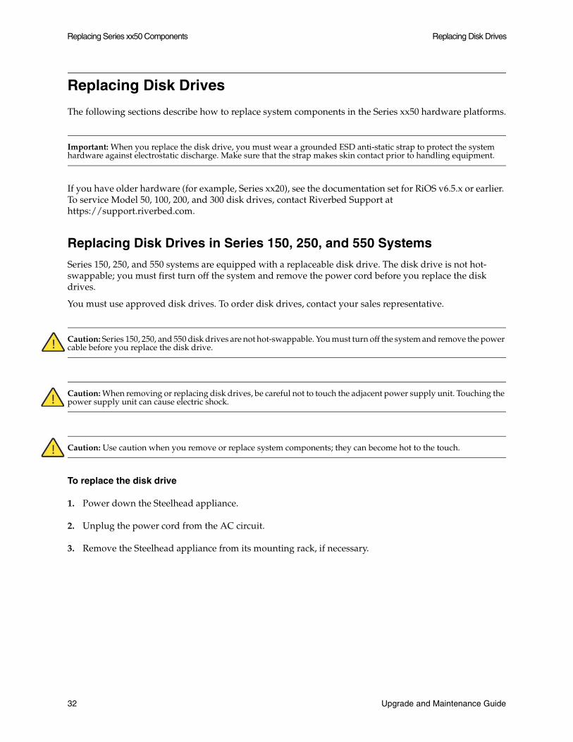
4. Remove the two locking screws on the back of the chassis.
Figure 2-1. Removing the Locking Screws
5. Position your thumbs on the top of the appliance and slide the cover back from the chassis.
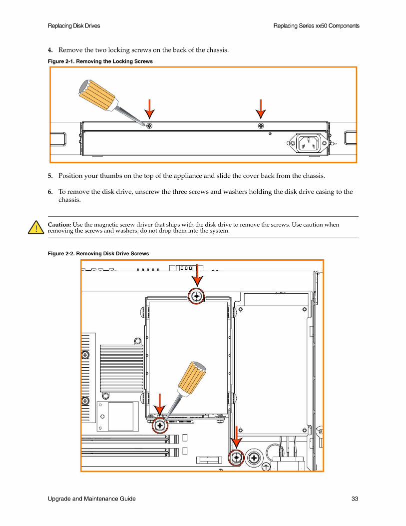
6. To remove the disk drive, unscrew the three screws and washers holding the disk drive casing to the chassis.
Caution: Use the magnetic screw driver that ships with the disk drive to remove the screws. Use caution when removing the screws and washers; do not drop them into the system.
Figure 2-2. Removing Disk Drive Screws
Upgrade and Maintenance Guide 33

Replacing Series xx50 Components Replacing Disk Drives
7. Remove the old disk drive with casing from the system.
8. Insert the new disk drive with casing in the same position and secure the casing with the three included screws.
9. Replace the system cover, making sure the tabs of the cover are under the front frame.
10. Plug the power cord into the AC circuit.
11. Power on the system.
The new disk drive runs through a self-test automatically. You do not need to set up or configure the new disk drive.
Replacing Disk Drives in Series 1050 and 2050 Systems
The 1050U, 1050L, 1050M, and 1050H platforms are equipped with replaceable, non-hot-swappable disk drives. The 1050_LR, 1050_MR, 1050_HR, and 2050 systems are equipped with replaceable, hot-swappable disk drives.
You must use approved disk drives. To order disk drives, contact your sales representative.
Important: When you replace disk drives, you must wear a grounded ESD anti-static strap to protect the system hardware against electrostatic discharge. Make sure that the strap makes skin contact prior to handling equipment.
Caution: Use caution when you remove or replace system components; they can become hot to the touch.
Important: The hard disk drives in Models 1050U, 1050L, 1050M, and 1050H are physically hot-swappable but cannot be removed while the system is powered on as this will disrupt system operation.
To replace the disk drive
1. For 1050U, 1050L, 1050M, and 1050H appliances, power down the Steelhead appliance and unplug the power cord from the AC circuit.
2. Open the bezel.
Press the buttons on each side of the bezel and pull toward you.
34 Upgrade and Maintenance Guide
Replacing Disk Drives Replacing Series xx50 Components
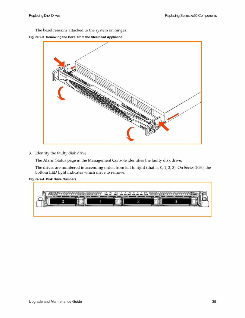
The bezel remains attached to the system on hinges.
Figure 2-3. Removing the Bezel from the Steelhead Appliance
3. Identify the faulty disk drive.
The Alarm Status page in the Management Console identifies the faulty disk drive.
The drives are numbered in ascending order, from left to right (that is, 0, 1, 2, 3). On Series 2050, the bottom LED light indicates which drive to remove.
Figure 2-4. Disk Drive Numbers
Upgrade and Maintenance Guide 35
Replacing Series xx50 Components Replacing Disk Drives
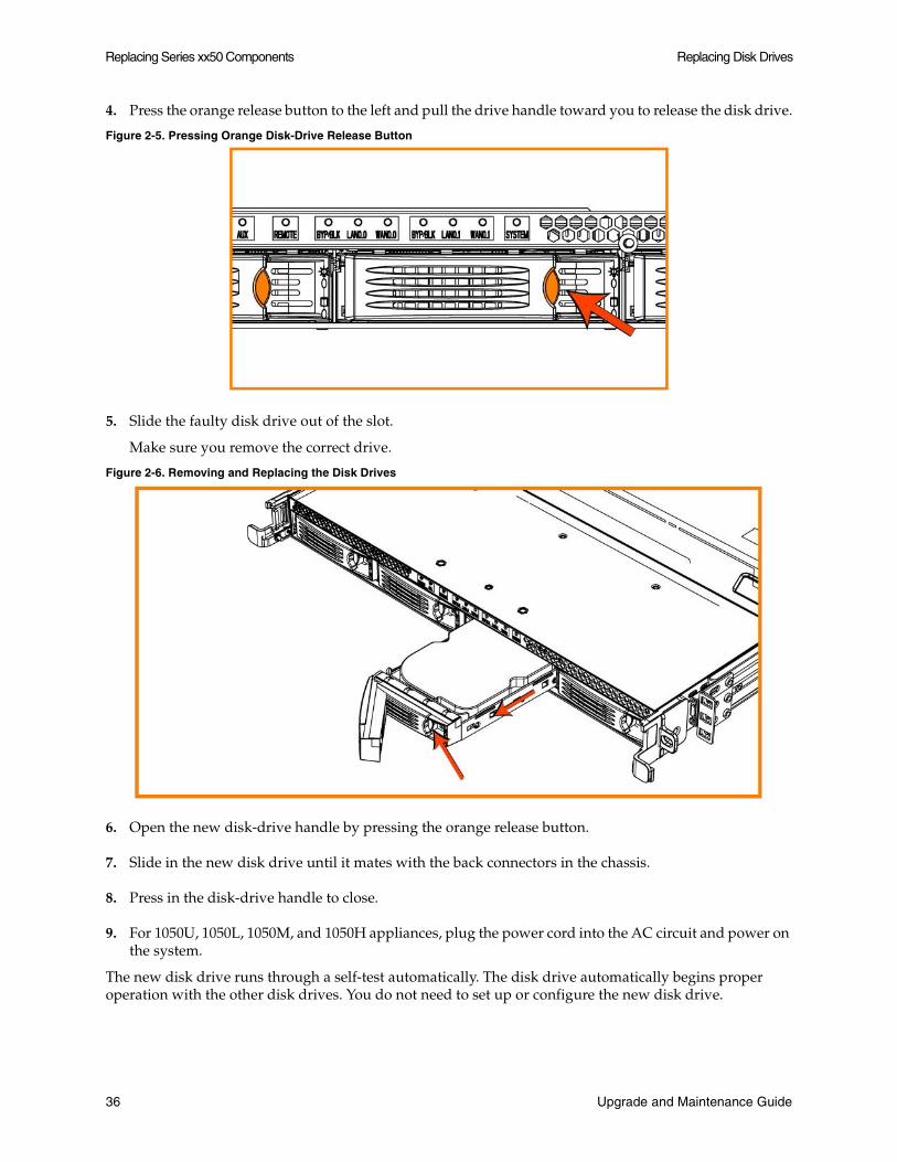
4. Press the orange release button to the left and pull the drive handle toward you to release the disk drive.
Figure 2-5. Pressing Orange Disk-Drive Release Button
5. Slide the faulty disk drive out of the slot.
Make sure you remove the correct drive.
Figure 2-6. Removing and Replacing the Disk Drives
6. Open the new disk-drive handle by pressing the orange release button.
7. Slide in the new disk drive until it mates with the back connectors in the chassis.
8. Press in the disk-drive handle to close.
9. For 1050U, 1050L, 1050M, and 1050H appliances, plug the power cord into the AC circuit and power on the system.
The new disk drive runs through a self-test automatically. The disk drive automatically begins proper operation with the other disk drives. You do not need to set up or configure the new disk drive.
36 Upgrade and Maintenance Guide

Replacing Disk Drives Replacing Series xx50 Components
Important: It takes approximately 3 to 4 hours, depending on the system load, to rebuild a new disk drive. When the disk drive has finished rebuilding, the system sends an email to the administrator user.
Replacing Disk Drives in Series 5050, 6050, IC 9350, and WWA xx10 Systems
Series 5050, 6050, IC 9350, WWA-510, WWA-710, WWA-2010, and WWA-3010 systems are equipped with replaceable, hot-swappable disk drives.
Important: Upgrading systems can impact the datastore. For example, upgrading from a 5050M to a 5050L clears the datastore, RSP data, PFS, and log files. For detailed information about the impact of upgrading your system on the datastore and RSP, see “Platform Requirements” on page 82.
You must use approved disk drives. To order disk drives, contact your sales representative.
Important: When you replace disk drives, you must wear a grounded ESD anti-static strap to protect the system hardware against electrostatic discharge. Make sure that the strap makes skin contact prior to handling equipment.
Caution: Use caution when you remove or replace system components; they can become hot to the touch.
To replace the disk drive
1. Open the bezel.
Press the buttons on each side of the bezel and pull toward you.
Upgrade and Maintenance Guide 37

Replacing Series xx50 Components Replacing Disk Drives
The bezel remains attached to the system on hinges.
Figure 2-7. Opening the Bezel on the Steelhead Appliance
2. Identify the faulty disk drive.
The Alarm Status page in the Management Console identifies the faulty disk drive.
The drives are numbered in ascending order, from left to right (that is, 0, 1, 2, 3). On Series 5050, 6050, IC 9350, WWA-510, WWA-710, WWA-2010, and WWA-3010 models the bottom LED light indicates which drive to remove.
Figure 2-8. Disk Drive Numbers
3. Press the orange release button to the left and pull the drive handle toward you to release the disk drive.
4. Slide the faulty disk drive out of the slot.
38 Upgrade and Maintenance Guide
Replacing Disk Drives Replacing Series xx50 Components
Make sure you remove the correct drive.
Figure 2-9. Removing and Replacing the Disk Drives
5. Open the new disk-drive handle by pressing the orange release button.
6. Slide in the new disk drive until it mates with the back connectors in the chassis.
7. Press in the disk-drive handle to close.
The new disk drive runs through a self-test automatically. The disk drive automatically begins proper operation with the other disk drives. You do not need to set up or configure the new disk drive.
It takes approximately 3 to 4 hours, depending on the system load, to rebuild a new disk drive. The administrator user receives email when the disk drive has finished rebuilding.
Replacing Disk Drives in Series 7050L and 7050M Systems
Series 7050L and 7050M systems are equipped with replaceable, hot-swappable disk drives.
Caution: Use caution when you remove or replace system components; they can become hot to the touch.
To replace the disk drive
1. Open the bezel.
Press the buttons on each side of the bezel and pull toward you.
Upgrade and Maintenance Guide 39

Replacing Series xx50 Components Replacing Disk Drives
The bezel remains attached to the system on hinges.
Figure 2-10. Opening the Bezel on the Steelhead Appliance
2. Identify the faulty disk drive.
The Alarm Status page in the Management Console identifies the faulty disk drive.
Figure 2-11. Disk Drive Numbers
Disk drive numbers 0 and 1 are HDD. Drive numbers 2 to 29 are SSD. A spare HDD is located in slot 31.
3. Press the release button to the right and pull the drive handle toward you to release the disk drive.
4. Slide the faulty disk drive out of the slot.
40 Upgrade and Maintenance Guide

Replacing Power Supply Units Replacing Series xx50 Components
Make sure you remove the correct drive.
Figure 2-12. Removing and Replacing the Disk Drives
5. Open the new disk-drive handle by pressing the release button.
6. Slide in the new disk drive until it mates with the back connectors in the chassis.
7. Press in the disk-drive handle to close.
The new disk drive runs through a self-test automatically. The disk drive automatically begins proper operation with the other disk drives. You do not need to set up or configure the new disk drive.
Replacing Power Supply Units
This section describes how to add or replace power supply units for the Series xx50 systems. This section includes the following procedures:
“Adding or Replacing Power Supply Units in Series 1050 and 2050 Systems” on page 41
“Replacing Power Supply Units in Series 5050, 6050, IC 9350, and WWA xx10 Systems” on page 44
Adding or Replacing Power Supply Units in Series 1050 and 2050 Systems
Series 1050 and 2050 systems are equipped with a replaceable, hot-swappable power supply unit. For redundant power supply, you can add a second power supply unit. This section describes how to add or replace a power supply unit in the Series 1050 and 2050.
You must use approved power supply units. To order power supply units, contact your sales representative.
Caution: Use gloves when replacing the power supply units; they can become hot to the touch.
Upgrade and Maintenance Guide 41

Replacing Series xx50 Components Replacing Power Supply Units
To replace a power supply unit
1. Locate the defective power supply unit and remove the power cord.
Power Supply 0 (PS0) is on the left and Power Supply 1 (PS1) is on the right.
2. Press the green release tab toward the black handle, and pull the power supply unit toward you.
Figure 2-13. Back Panel View of the Power Supply Units
3. Pull the power supply unit out of the chassis.
Figure 2-14. Removing the Power Supply Unit
Caution: Put the defective power supply unit aside; wait until it cools down before touching it.
4. Slide in the new power supply unit until it mates with the back connectors in the chassis.
When the power supply unit is pushed all the way in, the button clicks to the right.
5. Plug the AC power cord into the new power supply unit.
To add a power supply unit
1. Power down the system.
2. Disconnect the system from the electrical outlet and peripherals.
3. Loosen the locking screw on the back of the chassis.
42 Upgrade and Maintenance Guide

Replacing Power Supply Units Replacing Series xx50 Components
4. Position your thumbs in the indentations at the front of the appliance and slide the cover back from the chassis.
Figure 2-15. Removing the Chassis Cover
5. Remove the locking screw and the power supply slot-cover.
Figure 2-16. Removing Power Supply Locking Screw and Slot-Cover
6. Slide in the new power supply unit until it mates with the back connectors in the chassis.
Upgrade and Maintenance Guide 43
Replacing Series xx50 Components Replacing Power Supply Units
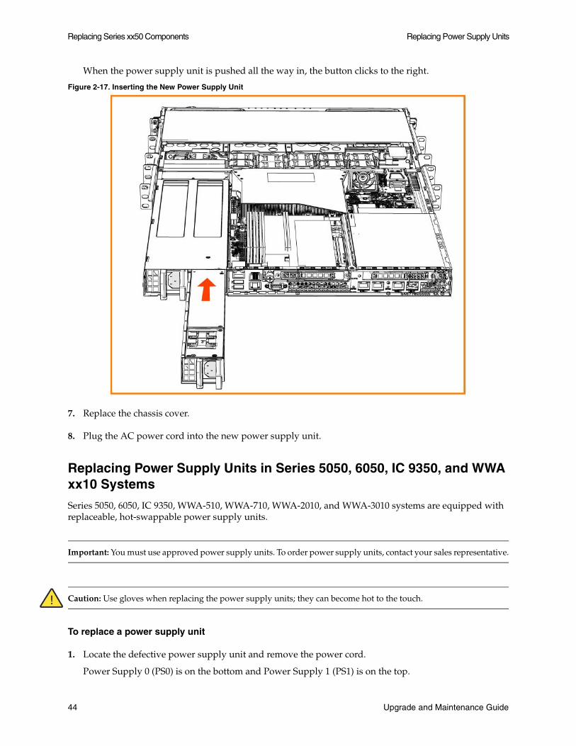
When the power supply unit is pushed all the way in, the button clicks to the right.
Figure 2-17. Inserting the New Power Supply Unit
7. Replace the chassis cover.
8. Plug the AC power cord into the new power supply unit.
Replacing Power Supply Units in Series 5050, 6050, IC 9350, and WWA xx10 Systems
Series 5050, 6050, IC 9350, WWA-510, WWA-710, WWA-2010, and WWA-3010 systems are equipped with replaceable, hot-swappable power supply units.
Important: You must use approved power supply units. To order power supply units, contact your sales representative.
Caution: Use gloves when replacing the power supply units; they can become hot to the touch.
To replace a power supply unit
1. Locate the defective power supply unit and remove the power cord.
Power Supply 0 (PS0) is on the bottom and Power Supply 1 (PS1) is on the top.
44 Upgrade and Maintenance Guide
Replacing Memory Replacing Series xx50 Components
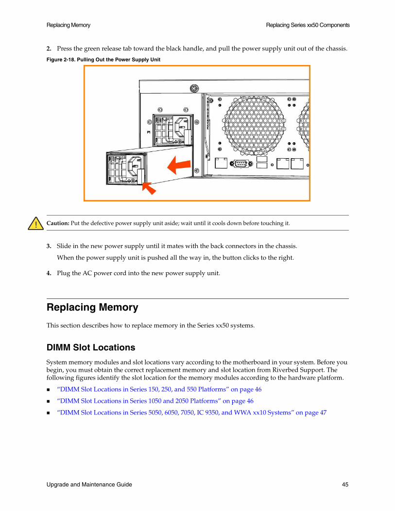
2. Press the green release tab toward the black handle, and pull the power supply unit out of the chassis.
Figure 2-18. Pulling Out the Power Supply Unit
Caution: Put the defective power supply unit aside; wait until it cools down before touching it.
3. Slide in the new power supply until it mates with the back connectors in the chassis.
When the power supply unit is pushed all the way in, the button clicks to the right.
4. Plug the AC power cord into the new power supply unit.
Replacing Memory
This section describes how to replace memory in the Series xx50 systems.
DIMM Slot Locations
System memory modules and slot locations vary according to the motherboard in your system. Before you begin, you must obtain the correct replacement memory and slot location from Riverbed Support. The following figures identify the slot location for the memory modules according to the hardware platform.
“DIMM Slot Locations in Series 150, 250, and 550 Platforms” on page 46
“DIMM Slot Locations in Series 1050 and 2050 Platforms” on page 46
“DIMM Slot Locations in Series 5050, 6050, 7050, IC 9350, and WWA xx10 Systems” on page 47
Upgrade and Maintenance Guide 45
Replacing Series xx50 Components Replacing Memory
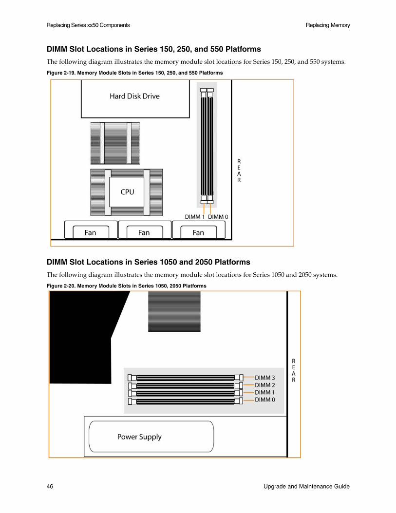
DIMM Slot Locations in Series 150, 250, and 550 Platforms
The following diagram illustrates the memory module slot locations for Series 150, 250, and 550 systems.
Figure 2-19. Memory Module Slots in Series 150, 250, and 550 Platforms
DIMM Slot Locations in Series 1050 and 2050 Platforms
The following diagram illustrates the memory module slot locations for Series 1050 and 2050 systems.
Figure 2-20. Memory Module Slots in Series 1050, 2050 Platforms
46 Upgrade and Maintenance Guide
Replacing Memory Replacing Series xx50 Components
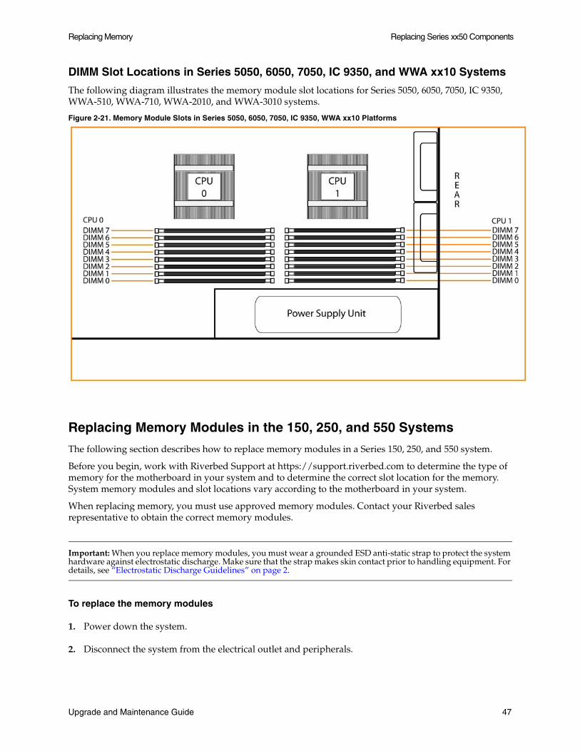
DIMM Slot Locations in Series 5050, 6050, 7050, IC 9350, and WWA xx10 Systems
The following diagram illustrates the memory module slot locations for Series 5050, 6050, 7050, IC 9350, WWA-510, WWA-710, WWA-2010, and WWA-3010 systems.
Figure 2-21. Memory Module Slots in Series 5050, 6050, 7050, IC 9350, WWA xx10 Platforms
Replacing Memory Modules in the 150, 250, and 550 Systems
The following section describes how to replace memory modules in a Series 150, 250, and 550 system.
Before you begin, work with Riverbed Support at https://support.riverbed.com to determine the type of memory for the motherboard in your system and to determine the correct slot location for the memory. System memory modules and slot locations vary according to the motherboard in your system.
When replacing memory, you must use approved memory modules. Contact your Riverbed sales representative to obtain the correct memory modules.
Important: When you replace memory modules, you must wear a grounded ESD anti-static strap to protect the system hardware against electrostatic discharge. Make sure that the strap makes skin contact prior to handling equipment. For details, see “Electrostatic Discharge Guidelines” on page 2.
To replace the memory modules
1. Power down the system.
2. Disconnect the system from the electrical outlet and peripherals.
Upgrade and Maintenance Guide 47
Replacing Series xx50 Components Replacing Memory
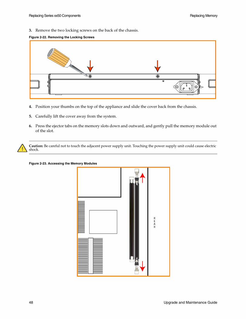
3. Remove the two locking screws on the back of the chassis.
Figure 2-22. Removing the Locking Screws
4. Position your thumbs on the top of the appliance and slide the cover back from the chassis.
5. Carefully lift the cover away from the system.
6. Press the ejector tabs on the memory slots down and outward, and gently pull the memory module out of the slot.
Caution: Be careful not to touch the adjacent power supply unit. Touching the power supply unit could cause electric shock.
Figure 2-23. Accessing the Memory Modules
48 Upgrade and Maintenance Guide
Replacing Memory Replacing Series xx50 Components
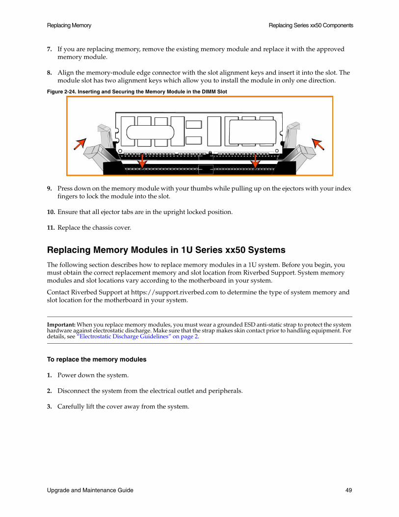
7. If you are replacing memory, remove the existing memory module and replace it with the approved memory module.
8. Align the memory-module edge connector with the slot alignment keys and insert it into the slot. The module slot has two alignment keys which allow you to install the module in only one direction.
Figure 2-24. Inserting and Securing the Memory Module in the DIMM Slot
9. Press down on the memory module with your thumbs while pulling up on the ejectors with your index fingers to lock the module into the slot.
10. Ensure that all ejector tabs are in the upright locked position.
11. Replace the chassis cover.
Replacing Memory Modules in 1U Series xx50 Systems
The following section describes how to replace memory modules in a 1U system. Before you begin, you must obtain the correct replacement memory and slot location from Riverbed Support. System memory modules and slot locations vary according to the motherboard in your system.
Contact Riverbed Support at https://support.riverbed.com to determine the type of system memory and slot location for the motherboard in your system.
Important: When you replace memory modules, you must wear a grounded ESD anti-static strap to protect the system hardware against electrostatic discharge. Make sure that the strap makes skin contact prior to handling equipment. For details, see “Electrostatic Discharge Guidelines” on page 2.
To replace the memory modules
1. Power down the system.
2. Disconnect the system from the electrical outlet and peripherals.
3. Carefully lift the cover away from the system.
Upgrade and Maintenance Guide 49
Replacing Series xx50 Components Replacing Memory
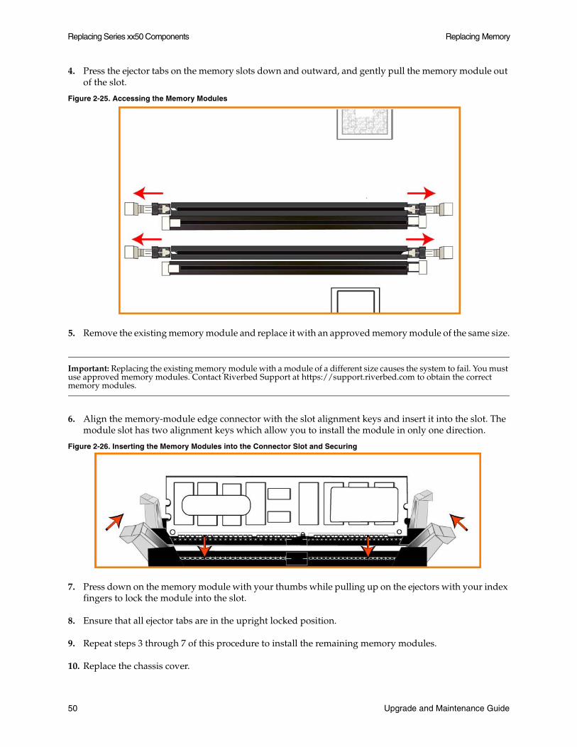
4. Press the ejector tabs on the memory slots down and outward, and gently pull the memory module out of the slot.
Figure 2-25. Accessing the Memory Modules
5. Remove the existing memory module and replace it with an approved memory module of the same size.
Important: Replacing the existing memory module with a module of a different size causes the system to fail. You must use approved memory modules. Contact Riverbed Support at https://support.riverbed.com to obtain the correct memory modules.
6. Align the memory-module edge connector with the slot alignment keys and insert it into the slot. The module slot has two alignment keys which allow you to install the module in only one direction.
Figure 2-26. Inserting the Memory Modules into the Connector Slot and Securing
7. Press down on the memory module with your thumbs while pulling up on the ejectors with your index fingers to lock the module into the slot.
8. Ensure that all ejector tabs are in the upright locked position.
9. Repeat steps 3 through 7 of this procedure to install the remaining memory modules.
10. Replace the chassis cover.
50 Upgrade and Maintenance Guide
Replacing Memory Replacing Series xx50 Components
Replacing Memory Modules in 3U Series xx50 Systems
The following section describes how to replace memory modules in 3U systems. Before you begin you must obtain the correct replacement memory and slot location from Riverbed Support. System memory modules and slot locations vary according to the motherboard in your system.
Contact Riverbed Support at https://support.riverbed.com to determine the type of system memory and slot location for the motherboard in your system.
Important: When you replace memory modules, you must wear a grounded ESD anti-static strap to protect the system hardware against electrostatic discharge. Make sure that the strap makes skin contact prior to handling equipment. For details, see “Electrostatic Discharge Guidelines” on page 2.
To remove the system cover
1. Power down the system.
2. Disconnect the system from the electrical outlet and peripherals.
3. Remove the top cover of the chassis.
To access the memory modules in the Series 5050, 6050, 7050, IC 9350, WWA-510, WWA-710, WWA-2010, and WWA-3010 systems, you must remove the system cooling shroud. The following figures illustrate the necessary steps to remove the cooling shroud.
Upgrade and Maintenance Guide 51
Replacing Series xx50 Components Replacing Memory
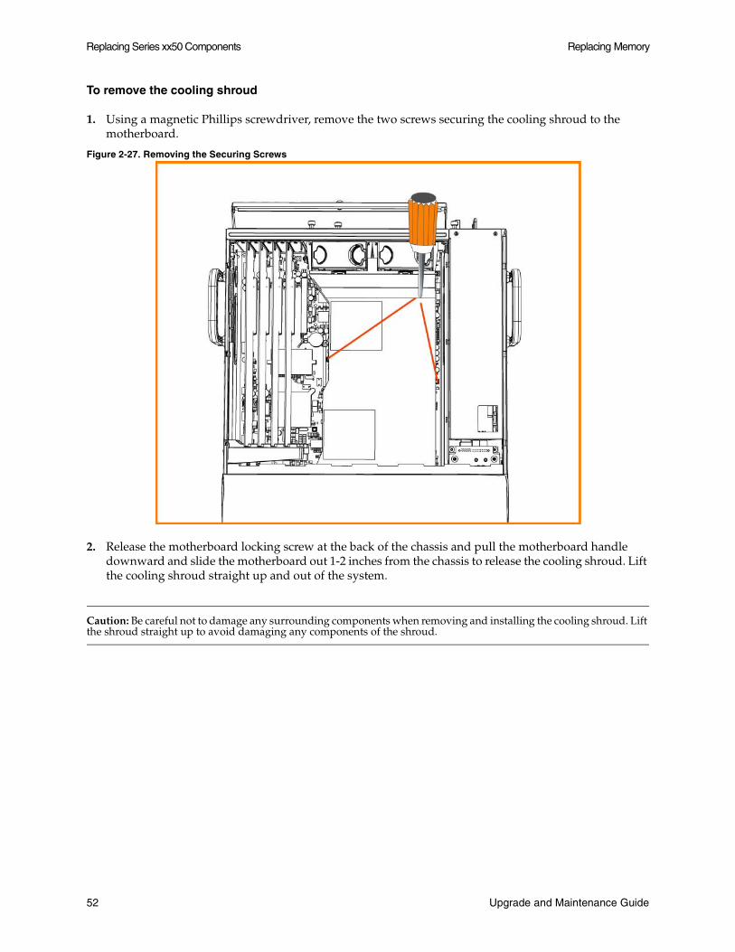
To remove the cooling shroud
1. Using a magnetic Phillips screwdriver, remove the two screws securing the cooling shroud to the motherboard.
Figure 2-27. Removing the Securing Screws
2. Release the motherboard locking screw at the back of the chassis and pull the motherboard handle downward and slide the motherboard out 1-2 inches from the chassis to release the cooling shroud. Lift the cooling shroud straight up and out of the system.
Caution: Be careful not to damage any surrounding components when removing and installing the cooling shroud. Lift the shroud straight up to avoid damaging any components of the shroud.
52 Upgrade and Maintenance Guide

Replacing Memory Replacing Series xx50 Components
Figure 2-28. Sliding the Motherboard Outward to Release the Cooling Shroud
To replace the memory modules
1. Press the ejector tabs on the memory module slot down and outward and gently pull the memory module out of the slot.
Figure 2-29. Accessing the Memory Modules
2. Hold the memory module on the outside edges to prevent damage to the module.
Figure 2-30. Proper Handling of the Memory Module
3. Remove the existing memory module and replace it with an approved memory module of the same size.
Upgrade and Maintenance Guide 53
Replacing Series xx50 Components Replacing Fans
Important: Replacing the existing memory module with a module of a different size causes the system to fail. You must use approved memory modules. Contact Riverbed Support at https://support.riverbed.com to obtain the correct memory modules.
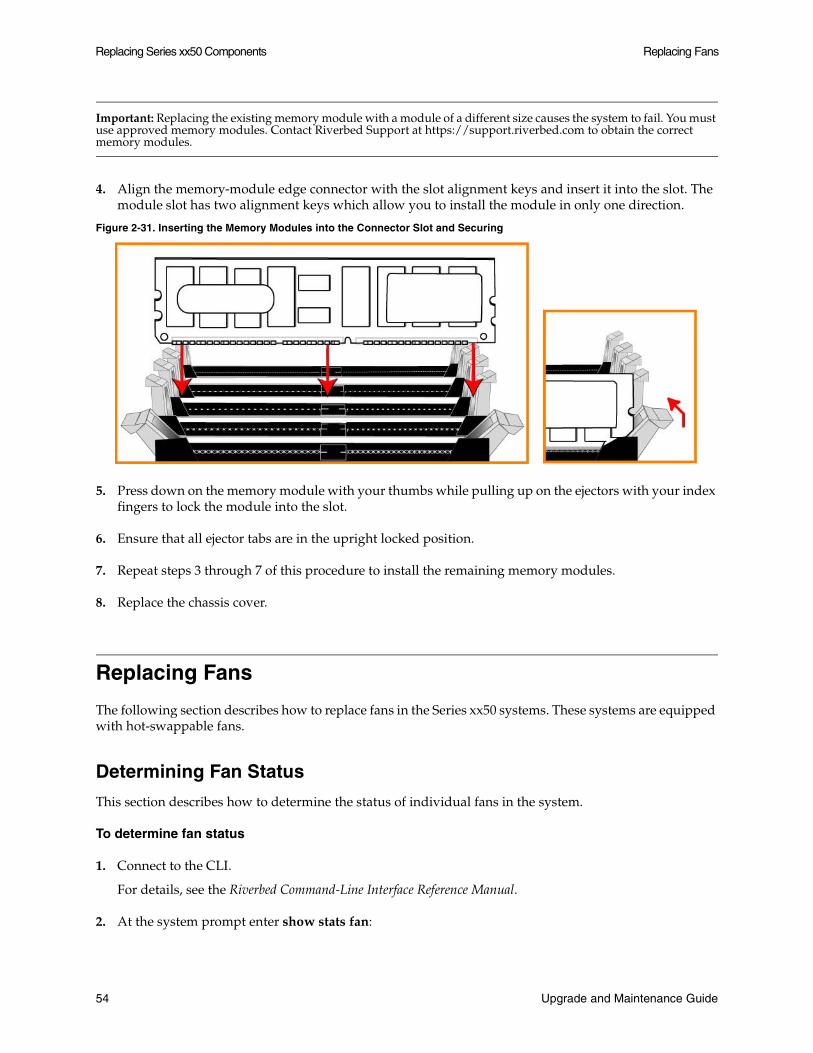
4. Align the memory-module edge connector with the slot alignment keys and insert it into the slot. The module slot has two alignment keys which allow you to install the module in only one direction.
Figure 2-31. Inserting the Memory Modules into the Connector Slot and Securing
5. Press down on the memory module with your thumbs while pulling up on the ejectors with your index fingers to lock the module into the slot.
6. Ensure that all ejector tabs are in the upright locked position.
7. Repeat steps 3 through 7 of this procedure to install the remaining memory modules.
8. Replace the chassis cover.
Replacing Fans
The following section describes how to replace fans in the Series xx50 systems. These systems are equipped with hot-swappable fans.
Determining Fan Status
This section describes how to determine the status of individual fans in the system.
To determine fan status
1. Connect to the CLI.
For details, see the Riverbed Command-Line Interface Reference Manual.
2. At the system prompt enter show stats fan:
54 Upgrade and Maintenance Guide
Replacing Fans Replacing Series xx50 Components
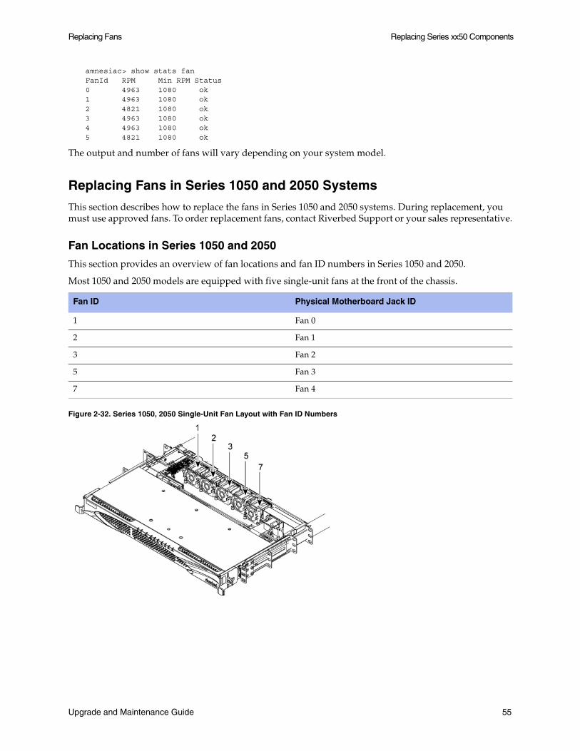
amnesiac> show stats fanFanId RPM Min RPM Status0 4963 1080 ok1 4963 1080 ok2 4821 1080 ok3 4963 1080 ok4 4963 1080 ok5 4821 1080 ok
The output and number of fans will vary depending on your system model.
Replacing Fans in Series 1050 and 2050 Systems
This section describes how to replace the fans in Series 1050 and 2050 systems. During replacement, you must use approved fans. To order replacement fans, contact Riverbed Support or your sales representative.
Fan Locations in Series 1050 and 2050
This section provides an overview of fan locations and fan ID numbers in Series 1050 and 2050.
Most 1050 and 2050 models are equipped with five single-unit fans at the front of the chassis.
Figure 2-32. Series 1050, 2050 Single-Unit Fan Layout with Fan ID Numbers
Fan ID Physical Motherboard Jack ID
1 Fan 0
2 Fan 1
3 Fan 2
5 Fan 3
7 Fan 4
Upgrade and Maintenance Guide 55

Replacing Series xx50 Components Replacing Fans
Early shipments of the Series 1050 and 2050 contain three single-unit fans and two dual-unit fans. Dual-unit fans are two fans encased in a single housing unit. Fans 3, 4 are a unit and fans 5, 6 are a unit.
If your appliance has a dual-unit fan that fails, the replacement fan will be a single-unit fan. If you are replacing a dual-unit fan with a single-unit fan, you need a supported software version. Minimum software versions are RiOS 4.1.7d, 5.0.5b, and 5.5.0a.
Figure 2-33. Dual-Unit Fans
Note: The dual-unit cooling fans can be noisy. Riverbed provided a fan replacement kit to replace the dual-unit fans with single-unit fans. For detailed instructions, see Installing Quiet Kit Fans in the Series 1050 and 2050 at https://support.riverbed.com/download.htm?filename=doc/technotes/1050_2050_quiet_fans.pdf
To replace fans in the Series 1050 and 2050 appliances
1. Loosen the locking screw on the back of the chassis.
Fan ID Physical Motherboard Jack ID
1 Fan 0
2 Fan 1
3, 4 Fan 2
5, 6 Fan 3
7 Fan 4
56 Upgrade and Maintenance Guide
Replacing Fans Replacing Series xx50 Components
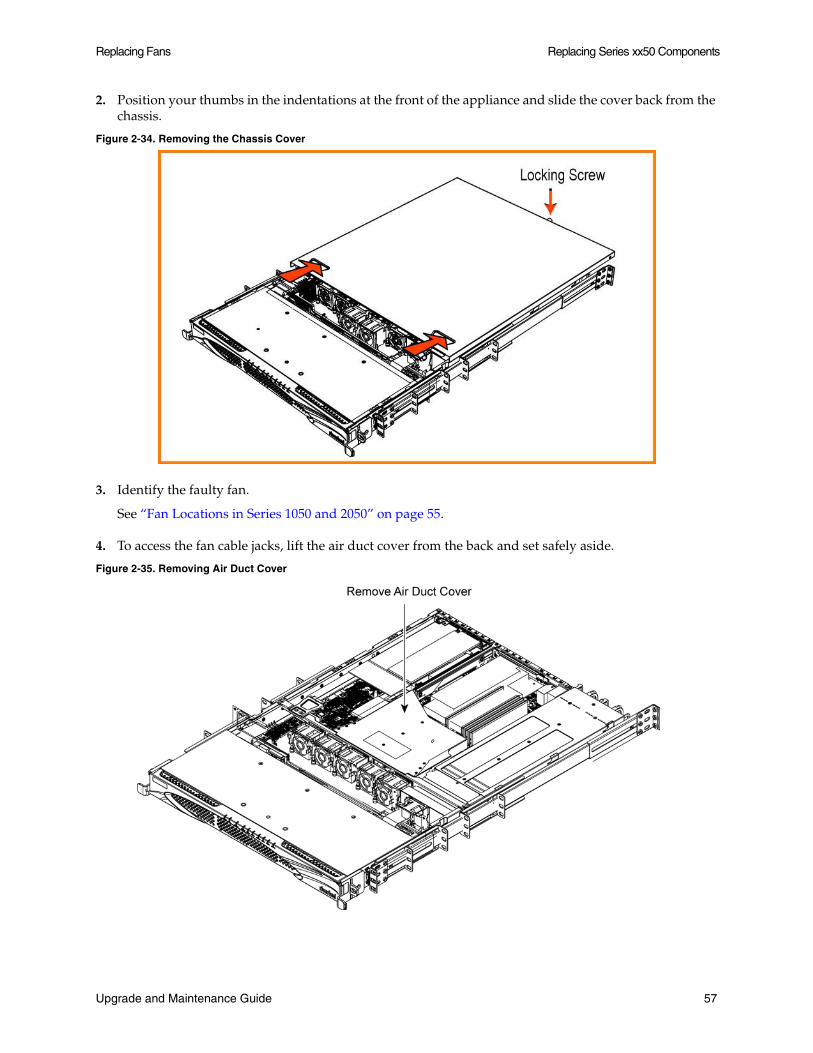
2. Position your thumbs in the indentations at the front of the appliance and slide the cover back from the chassis.
Figure 2-34. Removing the Chassis Cover
3. Identify the faulty fan.
See “Fan Locations in Series 1050 and 2050” on page 55.
4. To access the fan cable jacks, lift the air duct cover from the back and set safely aside.
Figure 2-35. Removing Air Duct Cover
Upgrade and Maintenance Guide 57

Replacing Series xx50 Components Replacing Fans
5. Unplug the fan cable from the fan cable jack.
Figure 2-36. Fan Cable Jack
6. After you have unplugged the fan cable from the jack, pull out the old fan.
Figure 2-37. Removing Single-Unit Fan
7. Route the fan cable under the chassis support beam.
8. Plug the cable of the replacement fan into the fan cable jack.
9. Seat the fan on the metal peg on the floor of the chassis.
The correct direction of fan airflow is toward the back of the chassis.
58 Upgrade and Maintenance Guide
Replacing Fans Replacing Series xx50 Components
10. To replace the air-duct cover, line up the tabs at the front of the cover with the grooves in the backplane wall.
11. Replace the chassis cover.
Note: The RiOS IPMI alarm triggers when the chassis cover opens on these models while the system is running. To clear this alarm, run the clear hardware error-log command in the CLI. For details, see the Riverbed Command-Line Interface Reference Manual.
Replacing Fans in the Series 5050, 6050, 7050, IC 9350, and WWA xx10 Systems
This section describes how to replace fans in the Series 5050, 6050, 7050, IC 9350, WWA-510, WWA-710, WWA-2010, and WWA-3010. These models are equipped with four hot-swappable fans at the front of the chassis and two hot-swappable fans at the back of the chassis.
Important: You must use approved fans. To order fans, contact your sales representative.
Upgrade and Maintenance Guide 59
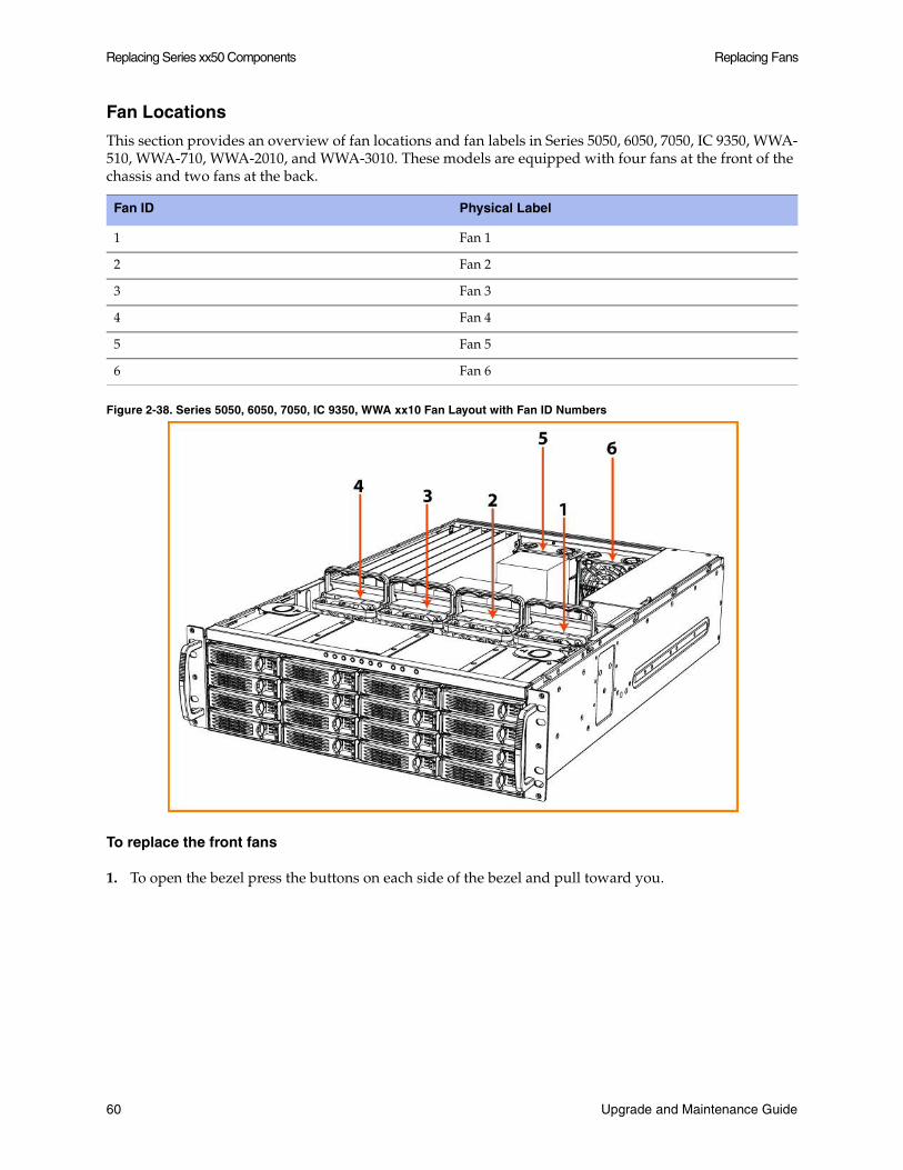
Replacing Series xx50 Components Replacing Fans
Fan Locations
This section provides an overview of fan locations and fan labels in Series 5050, 6050, 7050, IC 9350, WWA-510, WWA-710, WWA-2010, and WWA-3010. These models are equipped with four fans at the front of the chassis and two fans at the back.
Figure 2-38. Series 5050, 6050, 7050, IC 9350, WWA xx10 Fan Layout with Fan ID Numbers
To replace the front fans
1. To open the bezel press the buttons on each side of the bezel and pull toward you.
Fan ID Physical Label
1 Fan 1
2 Fan 2
3 Fan 3
4 Fan 4
5 Fan 5
6 Fan 6
60 Upgrade and Maintenance Guide
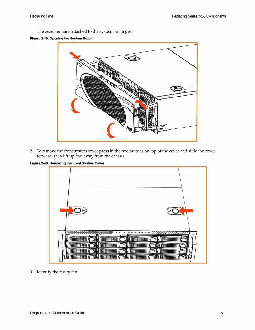
Replacing Fans Replacing Series xx50 Components
The bezel remains attached to the system on hinges.
Figure 2-39. Opening the System Bezel
2. To remove the front system cover press in the two buttons on top of the cover and slide the cover forward, then lift up and away from the chassis.
Figure 2-40. Removing the Front System Cover
3. Identify the faulty fan.
Upgrade and Maintenance Guide 61

Replacing Series xx50 Components Replacing Fans
4. Pull the fan release lever upwards and pull the fan up from the chassis.
Figure 2-41. Releasing the Fan
5. Plug the replacement fan into the chassis.
6. Replace the chassis front cover.
To replace the front cover insert the rear edge of the front cover below the front edge of the rear cover.
Note: The RiOS IPMI alarm triggers when the chassis cover opens on these models while the system is running. To clear this alarm, run the clear hardware error-log command in the CLI. For details, see the Riverbed Command-Line Interface Reference Manual.
62 Upgrade and Maintenance Guide
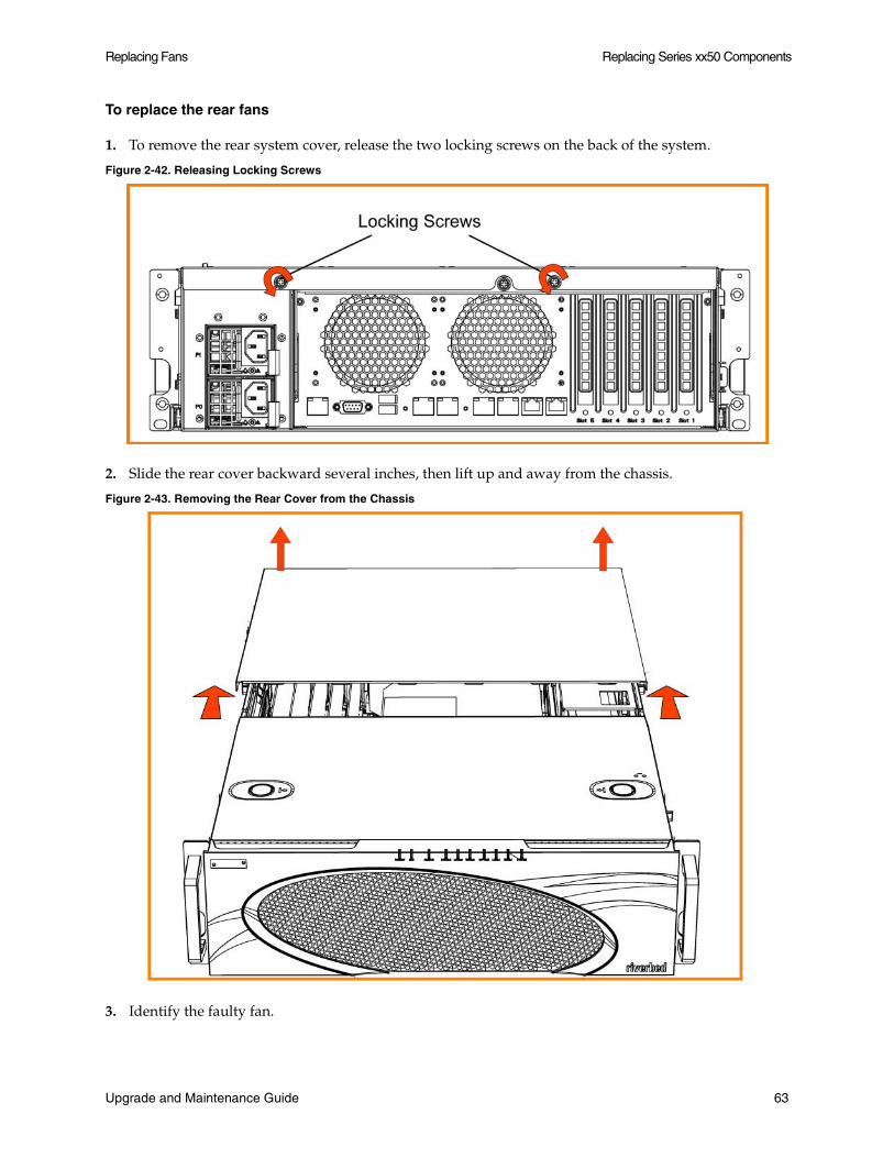
Replacing Fans Replacing Series xx50 Components
To replace the rear fans
1. To remove the rear system cover, release the two locking screws on the back of the system.
Figure 2-42. Releasing Locking Screws
2. Slide the rear cover backward several inches, then lift up and away from the chassis.
Figure 2-43. Removing the Rear Cover from the Chassis
3. Identify the faulty fan.
Upgrade and Maintenance Guide 63
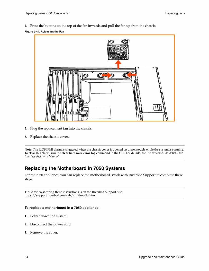
Replacing Series xx50 Components Replacing Fans
4. Press the buttons on the top of the fan inwards and pull the fan up from the chassis.
Figure 2-44. Releasing the Fan
5. Plug the replacement fan into the chassis.
6. Replace the chassis cover.
Note: The RiOS IPMI alarm is triggered when the chassis cover is opened on these models while the system is running. To clear this alarm, run the clear hardware error-log command in the CLI. For details, see the Riverbed Command-Line Interface Reference Manual.
Replacing the Motherboard in 7050 SystemsFor the 7050 appliance, you can replace the motherboard. Work with Riverbed Support to complete these steps.
Tip: A video showing these instructions is on the Riverbed Support Site: https://support.riverbed.com/kb/multimedia.htm.
To replace a motherboard in a 7050 appliance:
1. Power down the system.
2. Disconnect the power cord.
3. Remove the cover.
64 Upgrade and Maintenance Guide
Replacing Fans Replacing Series xx50 Components
4. Loosen the motherboard locking screw at the back of the chassis and pull the motherboard handle downward.
The motherboard will slide out 1 to 2 inches from the chassis.
5. Continue sliding the motherboard completely from the chassis.
Caution: Be sure to use both hands as the motherboard is heavy.
6. Following the same procedure, remove the replacement motherboard from the chassis.
Each motherboard ships within a chassis.
7. Place the two motherboards side by side.
This helps transfer the appropriate components.
8. Using a Phillips screwdriver, remove the flash drive from the replacement motherboard.
9. Discard this flash drive.
10. Remove the flash drive from the failed motherboard and add it to the replacement motherboard.
Align the pins and secure the flash drive with the Phillips screw.
11. Move the network cards from the failed motherboard to the replacement motherboard.
Move the cards one at a time and keep the cards in the same positions. You will need to remove the slot covers for each network card to transfer. See the Network Interface Card Installation Guide for details.
12. Move the SDR acceleration card to the new motherboard.
Use the same procedure as you did with the network cards.
13. Insert the new motherboard into the chassis. Carefully align it inside the chassis, and slide it into place.
14. For the last inch, move the handle into the upright position and secure it with the locking screw.
15. Replace the back cover and secure it with the fasteners.
16. Connect the power and start the appliance.
17. From the command line, enter configuration mode and type show licenses.
The output indicates the existing licenses are invalid.
18. Write down the MAC addresses of primary, aux, lan0_0, wan0_0, lan0_1 and wan0_1
19. Run the CLI command support motherboard update.
Important: When you run the command, do not press CTRL-C before the command completes. You will destroy the BIOS. Restart the appliance when prompted using the reload command.
Upgrade and Maintenance Guide 65
Replacing Series xx50 Components Replacing Fans
The commands take a while to complete as they copy the BIOS and reconfigure the MAC addresses.
The support motherboard update command is a hidden command.
20. When prompted, reboot the appliance using the reload command.
21. Once the appliance reboots, run the command show licenses and ensure that the licenses are valid.
22. Verify the MAC addresses of primary and aux interfaces.
The primary and aux interfaces should have new MAC addresses. The MAC addresses of lan0_0, wan0_0, lan0_1 and wan0_1 remain the same.
66 Upgrade and Maintenance Guide

CHAPTER 3 Upgrading Series xx55, xx60, and GC2000 Systems
This chapter describes how to upgrade a Series xx55, xx60, and GC2000 systems. It includes the following sections:
“Overview” on page 67
“Installing Licenses and Activating Specifications” on page 71
“Installing Hardware for Model Upgrades” on page 75
“Upgrading Memory for EX1260 Appliances” on page 79
Overview
A model upgrade enables you to add a license to an existing Series xx55, xx60, and GC2000 appliance to increase the capacity and the model number of the appliance within its platform family.
You can install licenses using the Riverbed Command-Line Interface (CLI) or the Steelhead Management Console. Model upgrades always preserve the configuration of the appliance.
In some cases, model upgrades require the installation of additional disk drives and memory modules. Upgrades that require the installation of additional hardware do not preserve the datastore.
Upgrade and Maintenance Guide 67

Upgrading Series xx55, xx60, and GC2000 Systems Overview
Model Upgrades and Platform Requirements
The table in this section describes the available model upgrades, the system requirements for the upgrade, and the impact of the upgrade on the appliance.
Source Model
Destination Model
Upgrade Requirements
Minimum Software Version
Impact on Datastore
Impact on Configuration
Reboot Required
CX255U CX255L License only RiOS v8.0.3a,v8.5.1
None None No
CX255U CX255M License only RiOS v8.0.3a,v8.5.1
None None No
CX255U CX255H License only RiOS v8.0.3a,v8.5.1
None None No
CX255L CX255M License only RiOS v8.0.3a,v8.5.1
None None No
CX255L CX255H License only RiOS v8.0.3a,v8.5.1
None None No
CX255M CX255H License only RiOS v8.0.3a,v8.5.1
None None No
CX555M CX555H License only RiOS v6.5.4,v7.0.1
None None No
CX755L CX755M License only RiOS v6.5.4,v7.0.1
None None No
CX755L CX755H License and Hardware Kit
RiOS v8.0.3,v8.5
Clears datastore and log files
None Yes
CX755M CX755H License and Hardware Kit
RiOS v8.0.3,v8.5
Clears datastore and log files
None Yes
CX1555L CX1555M License only RiOS v6.5.4,v7.0.1
None None No
CX1555L CX1555H License and Hardware Kit
RiOS v8.0.3,v8.5
Clears datastore and log files
None Yes
CX1555M CX1555H License and Hardware Kit
RiOS v8.0.3,v8.5
Clears datastore and log files
None Yes
CX5055M CX5055H License only RiOS v7.0.5,v8.0
None None No
EX560L EX560M License only EX 1.0 None None No
EX560L EX560H License only EX 1.0 None None No
EX560M EX560H License only EX 1.0 None None No
EX560G EX560L License only EX 1.0 None None Yes
EX560G EX560M License only EX 1.0 None None Yes
EX560G EX560H License only EX 1.0 None None Yes
68 Upgrade and Maintenance Guide
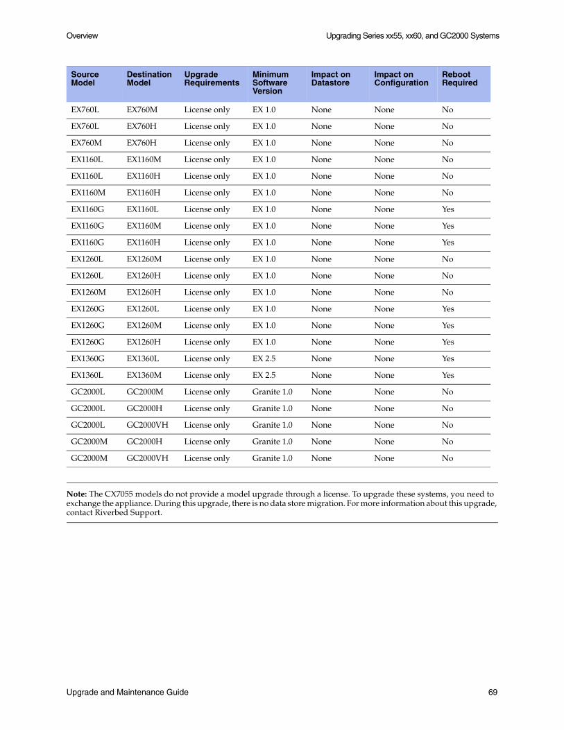
Overview Upgrading Series xx55, xx60, and GC2000 Systems
Note: The CX7055 models do not provide a model upgrade through a license. To upgrade these systems, you need to exchange the appliance. During this upgrade, there is no data store migration. For more information about this upgrade, contact Riverbed Support.
EX760L EX760M License only EX 1.0 None None No
EX760L EX760H License only EX 1.0 None None No
EX760M EX760H License only EX 1.0 None None No
EX1160L EX1160M License only EX 1.0 None None No
EX1160L EX1160H License only EX 1.0 None None No
EX1160M EX1160H License only EX 1.0 None None No
EX1160G EX1160L License only EX 1.0 None None Yes
EX1160G EX1160M License only EX 1.0 None None Yes
EX1160G EX1160H License only EX 1.0 None None Yes
EX1260L EX1260M License only EX 1.0 None None No
EX1260L EX1260H License only EX 1.0 None None No
EX1260M EX1260H License only EX 1.0 None None No
EX1260G EX1260L License only EX 1.0 None None Yes
EX1260G EX1260M License only EX 1.0 None None Yes
EX1260G EX1260H License only EX 1.0 None None Yes
EX1360G EX1360L License only EX 2.5 None None Yes
EX1360L EX1360M License only EX 2.5 None None Yes
GC2000L GC2000M License only Granite 1.0 None None No
GC2000L GC2000H License only Granite 1.0 None None No
GC2000L GC2000VH License only Granite 1.0 None None No
GC2000M GC2000H License only Granite 1.0 None None No
GC2000M GC2000VH License only Granite 1.0 None None No
Source Model
Destination Model
Upgrade Requirements
Minimum Software Version
Impact on Datastore
Impact on Configuration
Reboot Required
Upgrade and Maintenance Guide 69

Upgrading Series xx55, xx60, and GC2000 Systems Overview
Hardware Upgrade Kits
Some model upgrades require the installation of hardware. The hardware required for your model upgrade is contained in the Upgrade Kit shipped to you.
The following table lists the Upgrade Kit part numbers and hardware contents for xx55 series model upgrades requiring additional hardware.
For instructions on installing required hardware, see “Installing Hardware for Model Upgrades” on page 75.
Basic Steps
You perform the following steps to upgrade a model.
To perform a license-only upgrade
1. Install the model upgrade license.
You can install the model upgrade license in the CLI or the Management Console. For detailed information, see “Installing Licenses and Activating Specifications” on page 71. After you install the license, the system indicates the model specifications available and if hardware is required for activation.
2. Stop the service.
You need to stop the Steelhead optimization service to activate a model upgrade specification.
3. Activate the specification.
Activate the model upgrade specification in the CLI or the Management Console. For detailed information see “Installing Licenses and Activating Specifications” on page 71.
4. Reboot the system (if needed).
The system notifies you if a reboot is necessary.
5. Restart the service.
Upgrade Upgrade KitPart Number
Memory Modules Included in Kit
Hard Disks Included in Kit
CX755L--->CX755H UPG-CXA-755-L-H 1 x 2 GB Memory Module Hard disk casing with 1 x 250 GB HDD and 1 x 260 GB SSD
CX755M--->CX755H UPG-CXA-755-M-H 1 x 2 GB Memory Module Hard disk casing with 1 x 250 GB HDD and 1 x 260 GB SSD
CX1555L--->CX1555H UPG-CXA-1555-L-H None 2 x 160 GB SSD Disks
CX1555M--->CX1555H UPG-CXA-1555-M-H None 2 x 160 GB SSD Disks
70 Upgrade and Maintenance Guide

Installing Licenses and Activating Specifications Upgrading Series xx55, xx60, and GC2000 Systems
To perform a license and hardware kit upgrade
1. Install the model upgrade license.
You can install the model upgrade license in the CLI or the Management Console. For detailed information, see “Installing Licenses and Activating Specifications” on page 71. After you install the license, the system indicates the model specifications available and if hardware is required for activation.
2. Stop the service.
You need to stop the Steelhead optimization service to activate a model upgrade specification.
3. Activate the specification.
Activate the model upgrade specification in the CLI or the Management Console. For detailed information see “Installing Licenses and Activating Specifications” on page 71. When you activate the specification for an upgrade requiring hardware changes, the system shuts down.
4. Install the required hardware.
For detailed information, see “Installing Hardware for Model Upgrades” on page 75.
5. Power on the appliance.
The system reformats the hard drives and completes the upgrade.
Installing Licenses and Activating Specifications
The following section describes how to install model upgrade licenses and activate model specifications using the CLI or the Management Console.
After you install a model upgrade license, you must stop the Steelhead service to activate the model specification.
Model Upgrades Using the CLI
The following section describes how to install a model upgrade license and activate a specification using the CLI.
1. Connect to the Riverbed CLI.
For detailed information on using the CLI, see the Riverbed Command-Line Interface Reference Manual.
2. Enter enable mode; at the system prompt, enter enable:
amnesiac > enable
3. Enter configuration mode; at the system prompt, enter configure terminal:
amnesiac # configure terminalamnesiac (config) #
Upgrade and Maintenance Guide 71
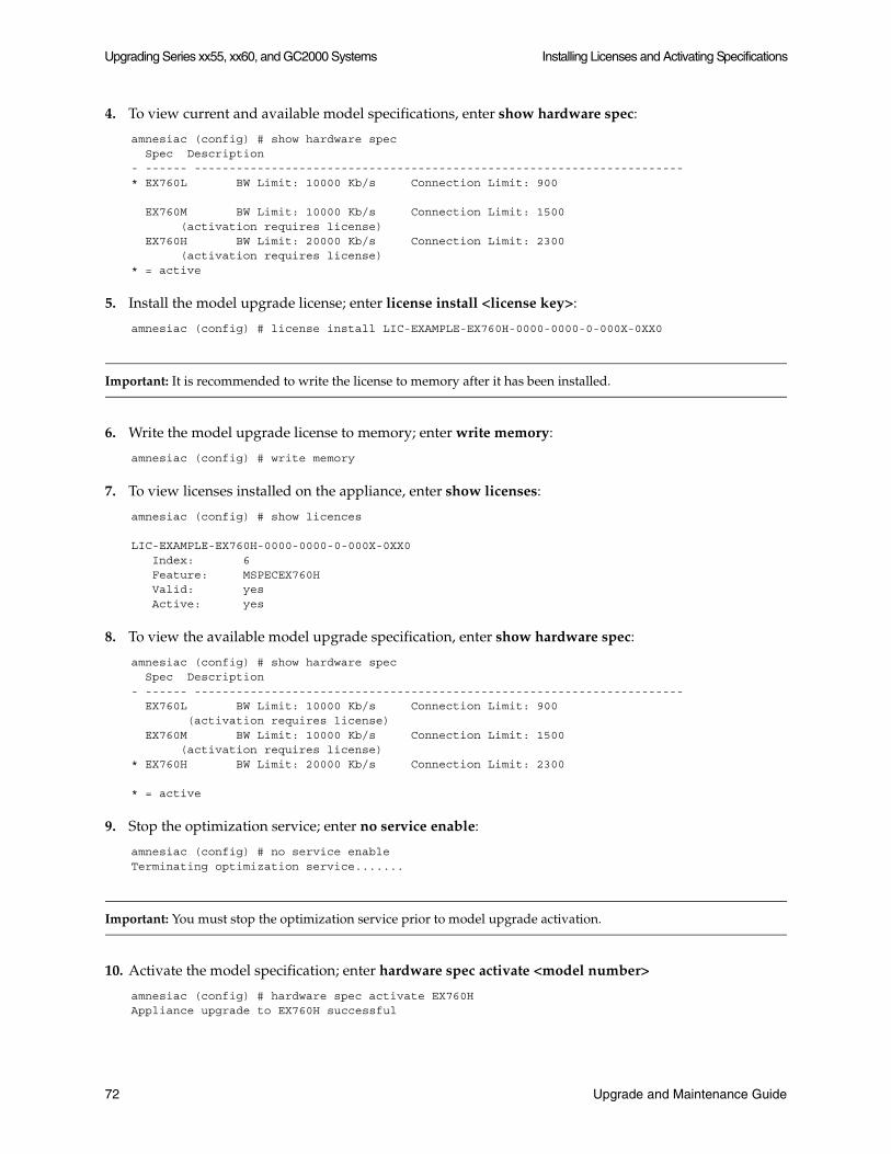
Upgrading Series xx55, xx60, and GC2000 Systems Installing Licenses and Activating Specifications
4. To view current and available model specifications, enter show hardware spec:
amnesiac (config) # show hardware spec Spec Description- ------ ----------------------------------------------------------------------* EX760L BW Limit: 10000 Kb/s Connection Limit: 900
EX760M BW Limit: 10000 Kb/s Connection Limit: 1500 (activation requires license) EX760H BW Limit: 20000 Kb/s Connection Limit: 2300 (activation requires license)* = active
5. Install the model upgrade license; enter license install <license key>:
amnesiac (config) # license install LIC-EXAMPLE-EX760H-0000-0000-0-000X-0XX0
Important: It is recommended to write the license to memory after it has been installed.
6. Write the model upgrade license to memory; enter write memory:
amnesiac (config) # write memory
7. To view licenses installed on the appliance, enter show licenses:
amnesiac (config) # show licences
LIC-EXAMPLE-EX760H-0000-0000-0-000X-0XX0 Index: 6 Feature: MSPECEX760H Valid: yes Active: yes
8. To view the available model upgrade specification, enter show hardware spec:
amnesiac (config) # show hardware spec Spec Description- ------ ---------------------------------------------------------------------- EX760L BW Limit: 10000 Kb/s Connection Limit: 900 (activation requires license) EX760M BW Limit: 10000 Kb/s Connection Limit: 1500 (activation requires license)* EX760H BW Limit: 20000 Kb/s Connection Limit: 2300
* = active
9. Stop the optimization service; enter no service enable:
amnesiac (config) # no service enableTerminating optimization service.......
Important: You must stop the optimization service prior to model upgrade activation.
10. Activate the model specification; enter hardware spec activate <model number>
amnesiac (config) # hardware spec activate EX760HAppliance upgrade to EX760H successful
72 Upgrade and Maintenance Guide
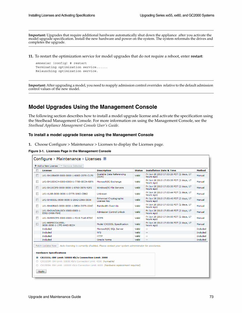
Installing Licenses and Activating Specifications Upgrading Series xx55, xx60, and GC2000 Systems
Important: Upgrades that require additional hardware automatically shut down the appliance after you activate the model upgrade specification. Install the new hardware and power on the system. The system reformats the drives and completes the upgrade.
11. To restart the optimization service for model upgrades that do not require a reboot, enter restart:
amnesiac (config) # restartTerminating optimization service......Relaunching optimization service.
Important: After upgrading a model, you need to reapply admission control overrides relative to the default admission control values of the new model.
Model Upgrades Using the Management Console
The following section describes how to install a model upgrade license and activate the specification using the Steelhead Management Console. For more information on using the Management Console, see the Steelhead Appliance Management Console User’s Guide.
To install a model upgrade license using the Management Console
1. Choose Configure > Maintenance > Licenses to display the Licenses page.
Figure 3-1. Licenses Page in the Management Console
Upgrade and Maintenance Guide 73

Upgrading Series xx55, xx60, and GC2000 Systems Installing Licenses and Activating Specifications
2. Click Add a New License to display the text box to add a new license.
3. Copy and paste the license key into the text box.
4. Click Add to add the license.
5. Click Save to save your settings permanently.
To activate a model upgrade specification using the Management Console
1. Choose Configure > Maintenance > Services to display the Services page.
2. Under Optimization Service click Stop to stop the Steelhead service.
3. Choose Configure > Maintenance > Licenses to display the Licenses page.
The hardware model specifications appear at the bottom of the page. The current specification appears in bold.
Figure 3-2. Hardware Model Specifications Appear on the Licenses Page of the Management Console
4. Select the model specification you want to activate.
If a model specification requires an appliance reboot after activation, the message activation reboots appliance appears.
5. Click Apply.
Important: Upgrades that require additional hardware automatically shut down the appliance after you activate the model upgrade specification. Install the new hardware and power on the system. The system reformats the drives and completes the upgrade.
6. If your model upgrade does not require the installation of additional hardware, click the Restart icon to restart the optimization service.
When the upgrade is complete, the appliance is transformed into the new model. The model number appears on the appliance banner in the upper-right corner of the screen. The appliance retains its original serial number.
Important: After upgrading a model, you need to reapply admission control overrides relative to the default admission control values of the new model.
74 Upgrade and Maintenance Guide
Installing Hardware for Model Upgrades Upgrading Series xx55, xx60, and GC2000 Systems
Installing Hardware for Model Upgrades
This section describes how to install the hardware for model upgrades from CX755L and CX755M to CX755H and from CX1555L and CX1555M to CX1555H models. It includes the following sections:
“Installing Required Memory and Disk Drives for CX755H Upgrades” on page 75
“Replacing Hard Disk Drives for CX1555H Upgrades” on page 77
For model upgrades that require additional hardware, you can install the license but cannot activate the specification until you install the required hardware.
Important: Model upgrades that require additional hardware do not preserve the datastore.
Installing Required Memory and Disk Drives for CX755H Upgrades
This section describes how to install memory modules and replacement disk drives for CX755L and CX755M to CX755H upgrades. For the disk drive upgrade, you replace the hard drive casing that contains two HDDs with a new casing that contains one SSD and one HDD.
Important: When you install or replace memory modules, you must wear a grounded ESD strap. For details, see “Electrostatic Discharge Guidelines” on page 2.
To upgrade memory and disk drives for CX755 model upgrades
1. When you activate the upgrade license, the system shuts down.
2. Disconnect the system from the electrical outlet.
3. Remove the chassis cover.
4. Install the Upgrade Kit memory module in DIMM slot 1.
Series CX755L and CX755M ship with a 2 GB memory module installed in DIMM slot 0; install the Upgrade Kit memory module in DIMM slot 1.
Upgrade and Maintenance Guide 75
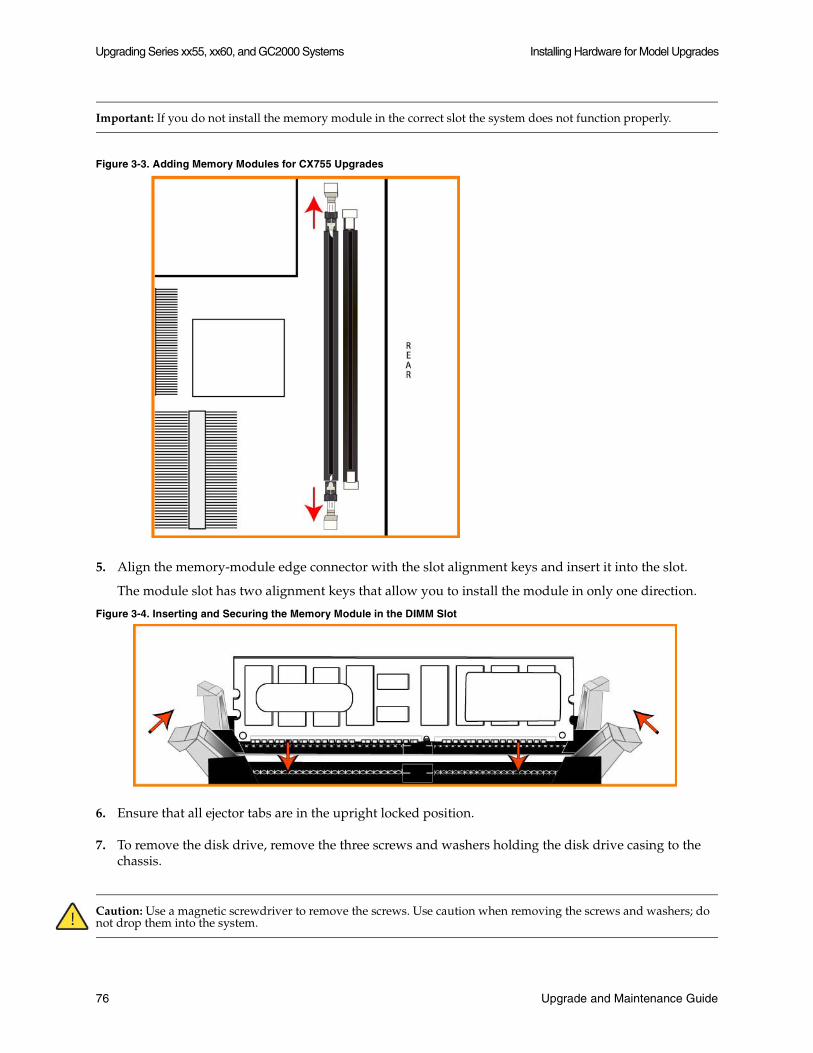
Upgrading Series xx55, xx60, and GC2000 Systems Installing Hardware for Model Upgrades
Important: If you do not install the memory module in the correct slot the system does not function properly.
Figure 3-3. Adding Memory Modules for CX755 Upgrades
5. Align the memory-module edge connector with the slot alignment keys and insert it into the slot.
The module slot has two alignment keys that allow you to install the module in only one direction.
Figure 3-4. Inserting and Securing the Memory Module in the DIMM Slot
6. Ensure that all ejector tabs are in the upright locked position.
7. To remove the disk drive, remove the three screws and washers holding the disk drive casing to the chassis.
Caution: Use a magnetic screwdriver to remove the screws. Use caution when removing the screws and washers; do not drop them into the system.
76 Upgrade and Maintenance Guide

Installing Hardware for Model Upgrades Upgrading Series xx55, xx60, and GC2000 Systems
8. Pull the entire disk drive casing upward and out of the chassis.
Figure 3-5. Removing the Disk Drive Casing from Chassis
9. Insert the new disk drive with casing in the same position and secure the casing to the chassis with the three screws.
10. Replace the system cover, making sure the tabs of the cover are under the front frame.
11. Plug the power cord into the AC circuit.
12. Power on the system.
The system automatically reformats the new drive. You do not need to set up or configure the new disk drive.
Replacing Hard Disk Drives for CX1555H Upgrades
This section describes how to install disk drives for CX1555H upgrades. For the upgrade, you replace two HDDs with two SSDs.
To upgrade the disk drives in the CX1555 systems
1. When you activate the upgrade license, the system shuts down.
2. Open the bezel.
Upgrade and Maintenance Guide 77
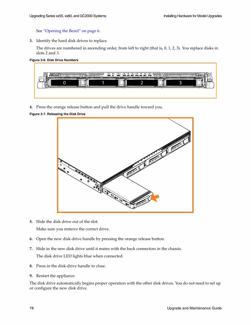
Upgrading Series xx55, xx60, and GC2000 Systems Installing Hardware for Model Upgrades
See “Opening the Bezel” on page 6.
3. Identify the hard disk drives to replace.
The drives are numbered in ascending order, from left to right (that is, 0, 1, 2, 3). You replace disks in slots 2 and 3.
Figure 3-6. Disk Drive Numbers
4. Press the orange release button and pull the drive handle toward you.
Figure 3-7. Releasing the Disk Drive
5. Slide the disk drive out of the slot.
Make sure you remove the correct drive.
6. Open the new disk-drive handle by pressing the orange release button.
7. Slide in the new disk drive until it mates with the back connectors in the chassis.
The disk drive LED lights blue when connected.
8. Press in the disk-drive handle to close.
9. Restart the appliance.
The disk drive automatically begins proper operation with the other disk drives. You do not need to set up or configure the new disk drive.
78 Upgrade and Maintenance Guide
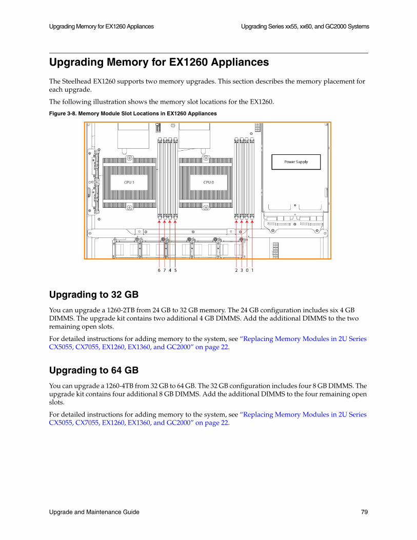
Upgrading Memory for EX1260 Appliances Upgrading Series xx55, xx60, and GC2000 Systems
Upgrading Memory for EX1260 Appliances
The Steelhead EX1260 supports two memory upgrades. This section describes the memory placement for each upgrade.
The following illustration shows the memory slot locations for the EX1260.
Figure 3-8. Memory Module Slot Locations in EX1260 Appliances
Upgrading to 32 GB
You can upgrade a 1260-2TB from 24 GB to 32 GB memory. The 24 GB configuration includes six 4 GB DIMMS. The upgrade kit contains two additional 4 GB DIMMS. Add the additional DIMMS to the two remaining open slots.
For detailed instructions for adding memory to the system, see “Replacing Memory Modules in 2U Series CX5055, CX7055, EX1260, EX1360, and GC2000” on page 22.
Upgrading to 64 GB
You can upgrade a 1260-4TB from 32 GB to 64 GB. The 32 GB configuration includes four 8 GB DIMMS. The upgrade kit contains four additional 8 GB DIMMS. Add the additional DIMMS to the four remaining open slots.
For detailed instructions for adding memory to the system, see “Replacing Memory Modules in 2U Series CX5055, CX7055, EX1260, EX1360, and GC2000” on page 22.
Upgrade and Maintenance Guide 79
Upgrading Series xx55, xx60, and GC2000 Systems Upgrading Memory for EX1260 Appliances
80 Upgrade and Maintenance Guide
CHAPTER 4 Upgrading Series xx50 Systems
This chapter describes how to upgrade a Series xx50 model within its platform family to increase the appliance optimization and storage capacities. It includes the following sections:
“Overview” on page 81
“Installing Licenses and Activating Specifications” on page 86
“Installing Hardware for Basic Model Upgrades” on page 91
“Installing Hardware for RAID Model Upgrades” on page 94
Important: After upgrading a model, desired admission control overrides must be reapplied relative to the default admission control values of the new model.
Important: When you replace memory modules, you must wear a grounded ESD anti-static strap to protect the system hardware against electrostatic discharge. Make sure that the strap makes skin contact prior to handling equipment. For details, see “Electrostatic Discharge Guidelines” on page 2.
Important: You must use approved hardware for the system to function properly. Installation of unapproved hardware can result in boot failure. To order Upgrade Kits, contact Riverbed Support at https://support.riverbed.com.
Overview
A model upgrade enables you to add a license and hardware to an existing Series xx50 appliance to increase the capacity and model number of the Steelhead appliance, within its platform family.
Model upgrades increase the WAN capacity and total number of optimized TCP connections for the appliance, RAID model upgrades also increase the size of the datastore.
Model upgrades require a license, and in some cases the installation of additional hard disk drives and memory modules. Licenses can be installed using the Riverbed Command-Line Interface (CLI) or the Steelhead Management Console. Upgrades that require the installation of additional hardware do not preserve the datastore. Model upgrades always preserve the configuration of the appliance.
Upgrade and Maintenance Guide 81
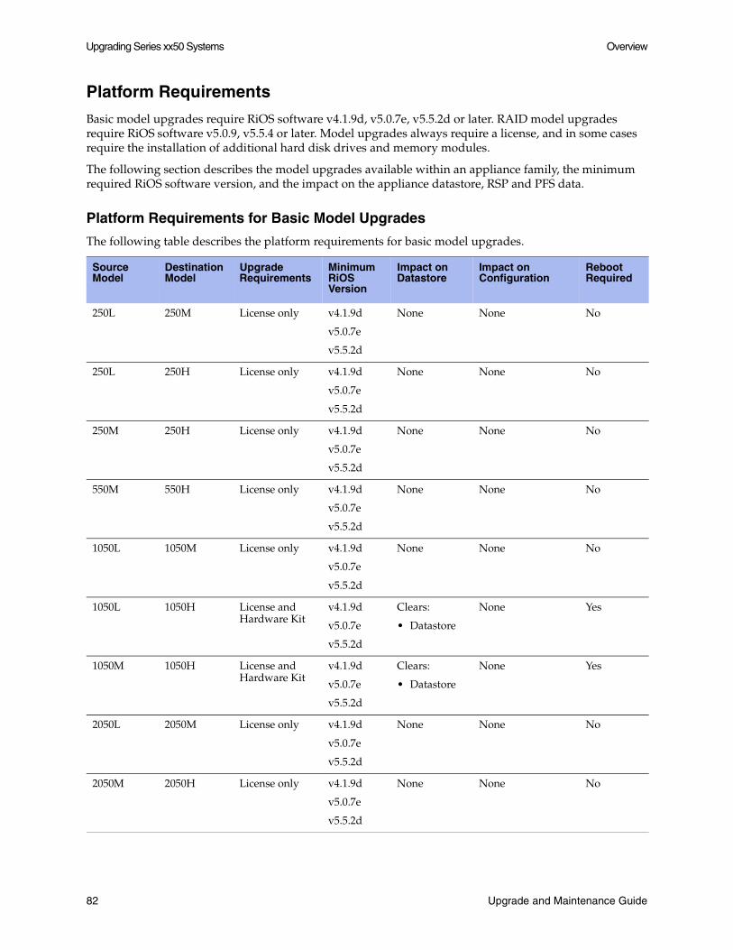
Upgrading Series xx50 Systems Overview
Platform Requirements
Basic model upgrades require RiOS software v4.1.9d, v5.0.7e, v5.5.2d or later. RAID model upgrades require RiOS software v5.0.9, v5.5.4 or later. Model upgrades always require a license, and in some cases require the installation of additional hard disk drives and memory modules.
The following section describes the model upgrades available within an appliance family, the minimum required RiOS software version, and the impact on the appliance datastore, RSP and PFS data.
Platform Requirements for Basic Model Upgrades
The following table describes the platform requirements for basic model upgrades.
Source Model
Destination Model
Upgrade Requirements
Minimum RiOS Version
Impact on Datastore
Impact on Configuration
Reboot Required
250L 250M License only v4.1.9d
v5.0.7e
v5.5.2d
None None No
250L 250H License only v4.1.9d
v5.0.7e
v5.5.2d
None None No
250M 250H License only v4.1.9d
v5.0.7e
v5.5.2d
None None No
550M 550H License only v4.1.9d
v5.0.7e
v5.5.2d
None None No
1050L 1050M License only v4.1.9d
v5.0.7e
v5.5.2d
None None No
1050L 1050H License and Hardware Kit
v4.1.9d
v5.0.7e
v5.5.2d
Clears:
• Datastore
None Yes
1050M 1050H License and Hardware Kit
v4.1.9d
v5.0.7e
v5.5.2d
Clears:
• Datastore
None Yes
2050L 2050M License only v4.1.9d
v5.0.7e
v5.5.2d
None None No
2050M 2050H License only v4.1.9d
v5.0.7e
v5.5.2d
None None No
82 Upgrade and Maintenance Guide

Overview Upgrading Series xx50 Systems
Platform Requirements for RAID Model Upgrades
The following table describes the platform requirements and datastore impact for RAID model upgrades.
Important: Both disk partitions must have software versions, v5.0.9, v5.5.4 or later, that support RAID models to perform a RAID model upgrade.
Important: After a model has been upgraded to a RAID model, it is not possible to downgrade the software version to a release previous to v5.0.9 or v5.4.4.
2050M 2050H License only v4.1.9d
v5.0.7e
v5.5.2d
None None No
5050L 5050M License only v5.5.7
v6.0.2
None None No
5050L 5050H License and Hardware Kit
v5.5.7
v6.0.2
Clears:
• Datastore
• RSP Data
• PFS
• Log Files
None Yes
5050M 5050H License and Hardware Kit
v4.1.9d
v5.0.7e
v5.5.2d
Clears:
• Datastore
• RSP Data
• PFS
• Log Files
None Yes
Source Model
Destination Model
Upgrade Requires
Minimum RiOS Version
Impact on Datastore
Impact on Configuration
Reboot Required
1050L 1050_LR License and Hardware Kit
v5.0.9
v5.5.4
Clears:
• Datastore
• RSP Data
• PFS
• Log Files
None Yes
1050M 1050_MR License and Hardware Kit
v5.0.9
v5.5.4
Clears:
• Datastore
• RSP Data
• PFS
• Log Files
None Yes
Source Model
Destination Model
Upgrade Requirements
Minimum RiOS Version
Impact on Datastore
Impact on Configuration
Reboot Required
Upgrade and Maintenance Guide 83
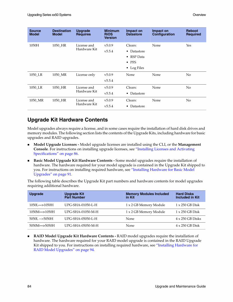
Upgrading Series xx50 Systems Overview
Upgrade Kit Hardware Contents
Model upgrades always require a license, and in some cases require the installation of hard disk drives and memory modules. The following section lists the contents of the Upgrade Kits, including hardware for basic upgrades and RAID upgrades.
Model Upgrade Licenses - Model upgrade licenses are installed using the CLI, or the Management Console. For instructions on installing upgrade licenses, see “Installing Licenses and Activating Specifications” on page 86.
Basic Model Upgrade Kit Hardware Contents - Some model upgrades require the installation of hardware. The hardware required for your model upgrade is contained in the Upgrade Kit shipped to you. For instructions on installing required hardware, see “Installing Hardware for Basic Model Upgrades” on page 91.
The following table describes the Upgrade Kit part numbers and hardware contents for model upgrades requiring additional hardware.
RAID Model Upgrade Kit Hardware Contents - RAID model upgrades require the installation of hardware. The hardware required for your RAID model upgrade is contained in the RAID Upgrade Kit shipped to you. For instructions on installing required hardware, see “Installing Hardware for RAID Model Upgrades” on page 94.
1050H 1050_HR License and Hardware Kit
v5.0.9
v5.5.4
Clears:
• Datastore
• RSP Data
• PFS
• Log Files
None Yes
1050_LR 1050_MR License only v5.0.9
v5.5.4
None None No
1050_LR 1050_HR License and Hardware Kit
v5.0.9
v5.5.4
Clears:
• Datastore
None No
1050_MR 1050_HR License and Hardware Kit
v5.0.9
v5.5.4
Clears:
• Datastore
None No
Upgrade Upgrade KitPart Number
Memory Modules Included in Kit
Hard Disks Included in Kit
1050L--->1050H UPG-SHA-01050-L-H 1 x 2 GB Memory Module 1 x 250 GB Disk
1050M--->1050H UPG-SHA-01050-M-H 1 x 2 GB Memory Module 1 x 250 GB Disk
5050L -->5050H UPG-SHA-05050-L-H None 4 x 250 GB Disks
5050M--->5050H UPG-SHA-05050-M-H None 4 x 250 GB Disk
Source Model
Destination Model
Upgrade Requires
Minimum RiOS Version
Impact on Datastore
Impact on Configuration
Reboot Required
84 Upgrade and Maintenance Guide

Overview Upgrading Series xx50 Systems
The following table describes the RAID Upgrade Kit part numbers and hardware contents.
Hardware Requirements
You must install Riverbed approved hardware for the system to function properly. The following table lists the minimum hardware requirements for each model.
RAID Upgrade Upgrade KitPart Number
Memory Modules Included in Kit
Hard Disks Included in Kit
1050L ---> 1050_LR RDK-001 None 3 x 250 GB Disk
1050M ---> 1050_MR RDK-002 None 3 x 250 GB Disk
1050H ---> 1050_HR RDK-003 None 2 x 250 GB Disk
1050_LR ---> 1050_MR UPG-SHA-01050-LR-MR None None
1050_LR ---> 1050_HR UPG-SHA-01050-LR-HR 1 x 2 GB Memory Module None
1050_MR ---> 1050_HR UPG-SHA-01050-MR-HR 1 x 2 GB Memory Module None
Model Minimum RAM Minimum # of HDDs
250L 1 x 1GB (1GB) N/A
250M 1 x 1GB (1GB) N/A
250H 1 x 1GB (1GB) N/A
550M 1 x 2GB (2GB) N/A
550H 1 x 2GB (2GB) N/A
1050U 2 x 2GB (2GB of RAM reserved for RSP) 1 x250 GB HDD
1050L 1 x 2GB (2GB) 1 x 250 GB HDD
1050M 1 x 2GB (2GB) 1 x 250 GB HDD
1050H 2 x 2GB (4GB) 2 x 250 GB HDD
1050_LR 1 x 2GB (2GB) 4 x 250 GB HDD
1050_MR 1 x 2GB (2GB) 4 x 250 GB HDD
1050_HR 2 x 2GB (4GB) 4 x 250 GB HDD
2050L 3 x 2GB (6GB) 4 x 250 GB HDD
2050M 3 x 2GB (6GB) 4 x 250 GB HDD
2050H 3 x 2GB (6GB) 4 x 250 GB HDD
5050L 4 x 2GB (8GB) 8 x 250 GB HDD
5050M 4 x 2GB (8GB) 8 x 250 GB HDD
5050H 4 x 2GB (8GB) 12 x 250 GB HDD
6050 12 x 2GB (24GB) 16 x 500 GB HDD
Upgrade and Maintenance Guide 85

Upgrading Series xx50 Systems Installing Licenses and Activating Specifications
Important: The hard disk drives in Models 1050U, 1050L, 1050M, and 1050H are physically hot-swappable, but if removed while the system is powered on, system operation is disrupted.
Note: RSP requires a license and an additional 2 GB of memory. For detailed information on RSP, see the Riverbed Services Platform Installation Guide. Contact Riverbed Support at https://support.riverbed.com for information on ordering RSP.
Basic Steps
You perform the following steps to upgrade a model:
1. Install the model upgrade license - The model upgrade license can be installed in the CLI or the Management Console. For detailed information, see “Installing Licenses and Activating Specifications” on page 86. After the license is installed, the system indicates the model specifications available and if hardware is required for activation.
2. Install the required hardware (if needed) - If you are upgrading to a 1050H, 5050H, 1050_LR, 1050_MR, or 1050_HR you must install the required hardware. For detailed information, see “Installing Hardware for Basic Model Upgrades” on page 91 or “Installing Hardware for RAID Model Upgrades” on page 94.
3. Stop the service - The Steelhead optimization service must be halted to activate a model upgrade specification.
4. Activate the specification - The model upgrade specification can be activated in the CLI, or the Management Console. For detailed information see “Installing Licenses and Activating Specifications” on page 86.
Note: For model upgrades that require additional hardware, the specification cannot be activated until the required hardware is installed.
5. Reboot the system (if needed) - For model upgrades that require additional hardware the system will notify you that a reboot is necessary. The Steelhead appliance reboots automatically after the required hardware is installed and the specification is activated in the CLI or Management Console.
6. Restart the service - The system does not reboot for upgrades that do not require the addition of hardware. License-only upgrades switch immediately to the new model after the license is installed, the Steelhead service is halted and the specification is activated. Restart the service after activating the upgrade specification.
Installing Licenses and Activating Specifications
The following section describes how to install model upgrade licenses and activate model specifications using the CLI (RiOS software v4.1.9d, v5.0.7e, v5.0.9, v5.5.2d, v5.5.4 and later) or the Management Console (RiOS software v5.0.7e, v5.0.9, v5.5.2d, v5.5.4 and later).
86 Upgrade and Maintenance Guide

Installing Licenses and Activating Specifications Upgrading Series xx50 Systems
After you install a model upgrade license, you must stop the Steelhead service to activate the model specification.
If additional hardware is required for the model upgrade, see “Installing Hardware for Basic Model Upgrades” on page 91, or “Installing Hardware for RAID Model Upgrades” on page 94.
Model Upgrades Using the CLI
The following section describes how to install a model upgrade license and activate a specification using the CLI. The CLI can be used to install licenses and activate specifications with RiOS software v4.1.9d, v5.0.7e, v5.0.9, v5.5.2d, v5.5.4 and later.
1. Connect to the Riverbed CLI.
For detailed information on using the CLI, see the Riverbed Command-Line Interface Reference Manual.
2. Enter enable mode; at the system prompt, enter enable:
amnesiac > enable
3. Enter configuration mode; at the system prompt, enter configure terminal:
amnesiac # configure terminalamnesiac (config) #
4. To view current and available model specifications, enter show hardware spec:
amnesiac (config) # show hardware spec Spec Description- ------ ----------------------------------------------------------------------* 1050_LR BW Limit: 6000 KB/s Connection Limit: 800 (activation requires license) 1050_MR BW Limit: 6000 KB/s Connection Limit: 1300 (activation requires license) 1050H BW Limit: 10000 KB/s Connection Limit: 2300
1050_HR BW Limit: 10000 KB/s Connection Limit: 2300 (activation requires license)* = active
5. To install the model upgrade license, enter license install <license key>:
amnesiac (config) # license install LIC-EXAMPLE1050_MR-0000-0000-0-000X-0XX0
Important: It is recommended to write the license to memory after it has been installed.
6. To write the model upgrade license to memory, enter write memory:
amnesiac (config) # write memory
7. To view licenses installed on the appliance, enter show licenses:
amnesiac (config) # show licences
LIC-EXAMPLE1050_MR-0000-0000-0-000X-0XX0 Index: 6 Feature: MSPEC1050_MR Valid: yes Active: yes
Upgrade and Maintenance Guide 87
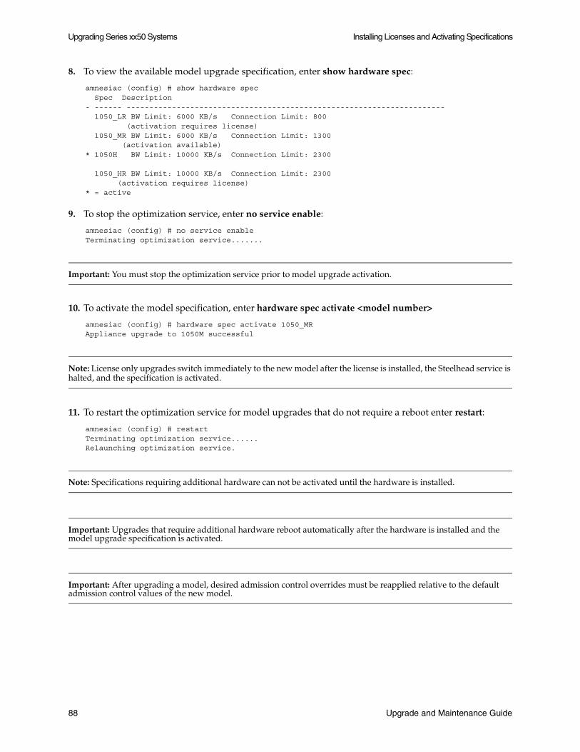
Upgrading Series xx50 Systems Installing Licenses and Activating Specifications
8. To view the available model upgrade specification, enter show hardware spec:
amnesiac (config) # show hardware spec Spec Description- ------ ---------------------------------------------------------------------- 1050_LR BW Limit: 6000 KB/s Connection Limit: 800 (activation requires license) 1050_MR BW Limit: 6000 KB/s Connection Limit: 1300 (activation available)* 1050H BW Limit: 10000 KB/s Connection Limit: 2300
1050_HR BW Limit: 10000 KB/s Connection Limit: 2300 (activation requires license)* = active
9. To stop the optimization service, enter no service enable:
amnesiac (config) # no service enableTerminating optimization service.......
Important: You must stop the optimization service prior to model upgrade activation.
10. To activate the model specification, enter hardware spec activate <model number>
amnesiac (config) # hardware spec activate 1050_MRAppliance upgrade to 1050M successful
Note: License only upgrades switch immediately to the new model after the license is installed, the Steelhead service is halted, and the specification is activated.
11. To restart the optimization service for model upgrades that do not require a reboot enter restart:
amnesiac (config) # restartTerminating optimization service......Relaunching optimization service.
Note: Specifications requiring additional hardware can not be activated until the hardware is installed.
Important: Upgrades that require additional hardware reboot automatically after the hardware is installed and the model upgrade specification is activated.
Important: After upgrading a model, desired admission control overrides must be reapplied relative to the default admission control values of the new model.
88 Upgrade and Maintenance Guide

Installing Licenses and Activating Specifications Upgrading Series xx50 Systems
Model Upgrades Using the Management Console
The following section describes how to install a model upgrade license and activate the specification using the Steelhead Management Console. Using the Management Console to install licenses and activate specifications requires RiOS software v5.0.7e, v5.0.9, v5.5.2d, v5.5.4 or later. For more information on using the Management Console, see the Steelhead Appliance Management Console User’s Guide.
To install a model upgrade license using the Management Console:
1. Choose Configure > Maintenance > Licenses to display the Licenses page.
Figure 4-1. Licenses Page in the Management Console
2. Click Add a New License to display the text box to add a new license.
3. Copy and paste the provided license key into the text box.
4. Click Add to add the license.
5. Click Save to save your settings permanently.
To activate a model upgrade specification using the Management Console:
1. Choose Configure > Maintenance > Services to display the Services page.
2. Under Optimization Service click Stop to stop the Steelhead service.
3. Choose Configure > Maintenance > Licenses to display the Licenses page.
Upgrade and Maintenance Guide 89
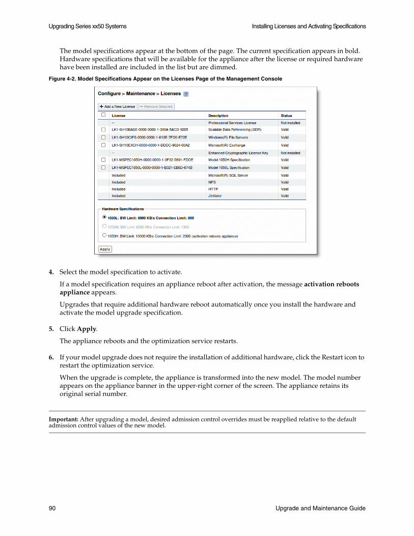
Upgrading Series xx50 Systems Installing Licenses and Activating Specifications
The model specifications appear at the bottom of the page. The current specification appears in bold. Hardware specifications that will be available for the appliance after the license or required hardware have been installed are included in the list but are dimmed.
Figure 4-2. Model Specifications Appear on the Licenses Page of the Management Console
4. Select the model specification to activate.
If a model specification requires an appliance reboot after activation, the message activation reboots appliance appears.
Upgrades that require additional hardware reboot automatically once you install the hardware and activate the model upgrade specification.
5. Click Apply.
The appliance reboots and the optimization service restarts.
6. If your model upgrade does not require the installation of additional hardware, click the Restart icon to restart the optimization service.
When the upgrade is complete, the appliance is transformed into the new model. The model number appears on the appliance banner in the upper-right corner of the screen. The appliance retains its original serial number.
Important: After upgrading a model, desired admission control overrides must be reapplied relative to the default admission control values of the new model.
90 Upgrade and Maintenance Guide
Installing Hardware for Basic Model Upgrades Upgrading Series xx50 Systems
Installing Hardware for Basic Model Upgrades
This section describes how to install the hardware for basic model upgrades including 1050L and 1050M to 1050H and 5050M to 5050H, that require additional hard disk drives and memory modules. For model upgrades that require additional hardware the license can be installed but the specification can not be activated until the required hardware is installed. It includes the following sections:
“Installing Required Memory Modules for 1050L and 1050M to 1050H Upgrades” on page 91
“Installing Required Hard Disk Drives for 1050L and 1050M to 1050H Upgrades” on page 93
“Installing Required Hard Disk Drives for 5050M to 5050H Upgrades” on page 93
Important: Model upgrades which require the addition of hardware do not preserve the datastore.
Installing Required Memory Modules for 1050L and 1050M to 1050H Upgrades
The following section describes how to install memory modules for 1050L and 1050M to 1050H upgrades.
Important: When you install or replace memory modules, you must wear a grounded ESD strap. For details, see “Electrostatic Discharge Guidelines” on page 2.
To install memory modules for 1050L and 1050M to 1050H
1. Power down and disconnect the system from the electrical outlet.
2. Remove the chassis cover.
3. Install the Upgrade Kit memory module in the next available slot in ascending numerical number.
Series 1050L and 1050M ship with a 2GB memory module installed in DIMM slot 0; install the Upgrade Kit memory module in DIMM slot 1.
Upgrade and Maintenance Guide 91
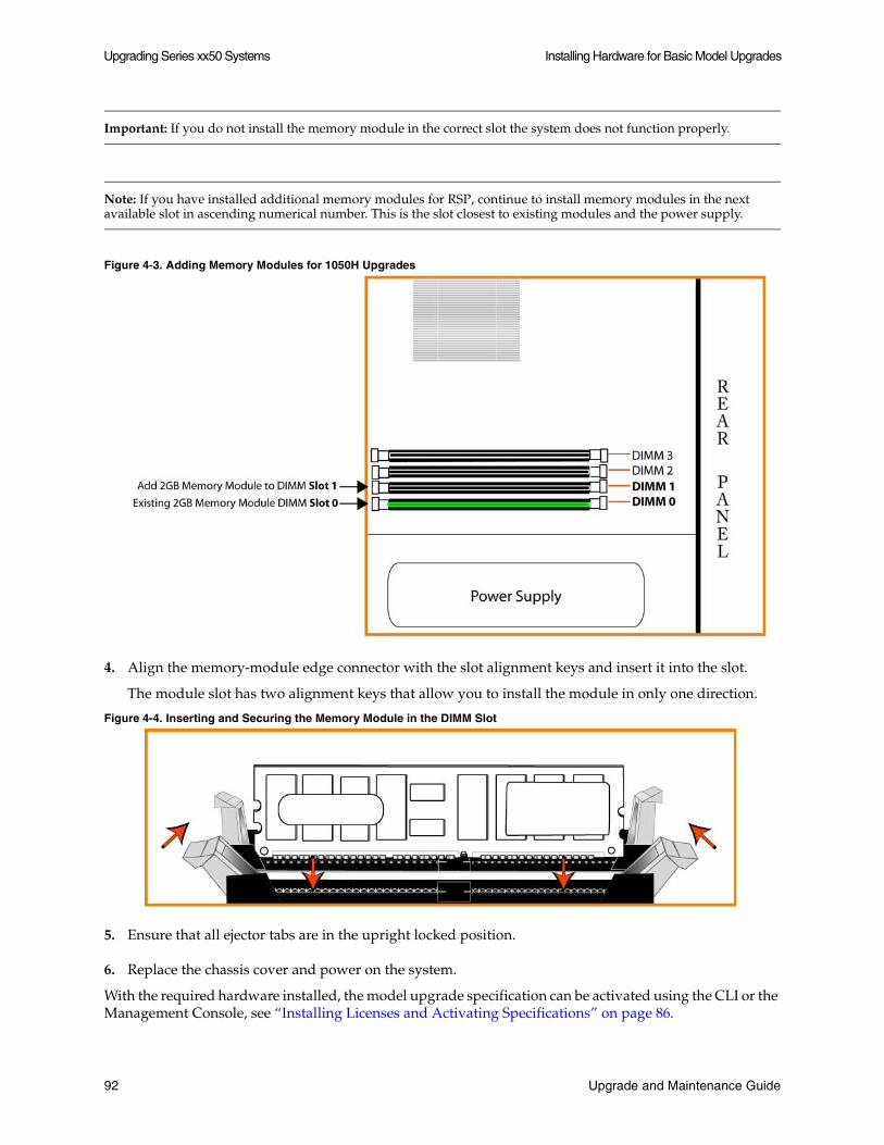
Upgrading Series xx50 Systems Installing Hardware for Basic Model Upgrades
Important: If you do not install the memory module in the correct slot the system does not function properly.
Note: If you have installed additional memory modules for RSP, continue to install memory modules in the next available slot in ascending numerical number. This is the slot closest to existing modules and the power supply.
Figure 4-3. Adding Memory Modules for 1050H Upgrades
4. Align the memory-module edge connector with the slot alignment keys and insert it into the slot.
The module slot has two alignment keys that allow you to install the module in only one direction.
Figure 4-4. Inserting and Securing the Memory Module in the DIMM Slot
5. Ensure that all ejector tabs are in the upright locked position.
6. Replace the chassis cover and power on the system.
With the required hardware installed, the model upgrade specification can be activated using the CLI or the Management Console, see “Installing Licenses and Activating Specifications” on page 86.
92 Upgrade and Maintenance Guide

Installing Hardware for Basic Model Upgrades Upgrading Series xx50 Systems
Installing Required Hard Disk Drives for 1050L and 1050M to 1050H Upgrades
The following section describes how to install disk drives for 1050L and 1050M to 1050H upgrades.
To install HDDs for 1050L and 1050M to 1050H upgrades
1. Open the new disk-drive handle by pressing the orange release button.
2. Install the Upgrade Kit disk drive in Slot 1 for 1050L and 1050M to 1050H upgrades.
Figure 4-5. Adding Disk Drives for 1050H Upgrades
3. Slide in the new disk drive until it mates with the back connectors in the chassis.
4. Press in the disk-drive handle to close.
5. With the required hardware installed, the upgrade specification can be activated using the CLI or the Management Console, see “Installing Licenses and Activating Specifications” on page 86.
Installing Required Hard Disk Drives for 5050M to 5050H Upgrades
The following section describes how to install disk drives for 5050M to 5050H upgrades.
To install HDDs for 5050M to 5050H upgrades
1. Open the new disk-drive handle by pressing the orange release button.
Upgrade and Maintenance Guide 93
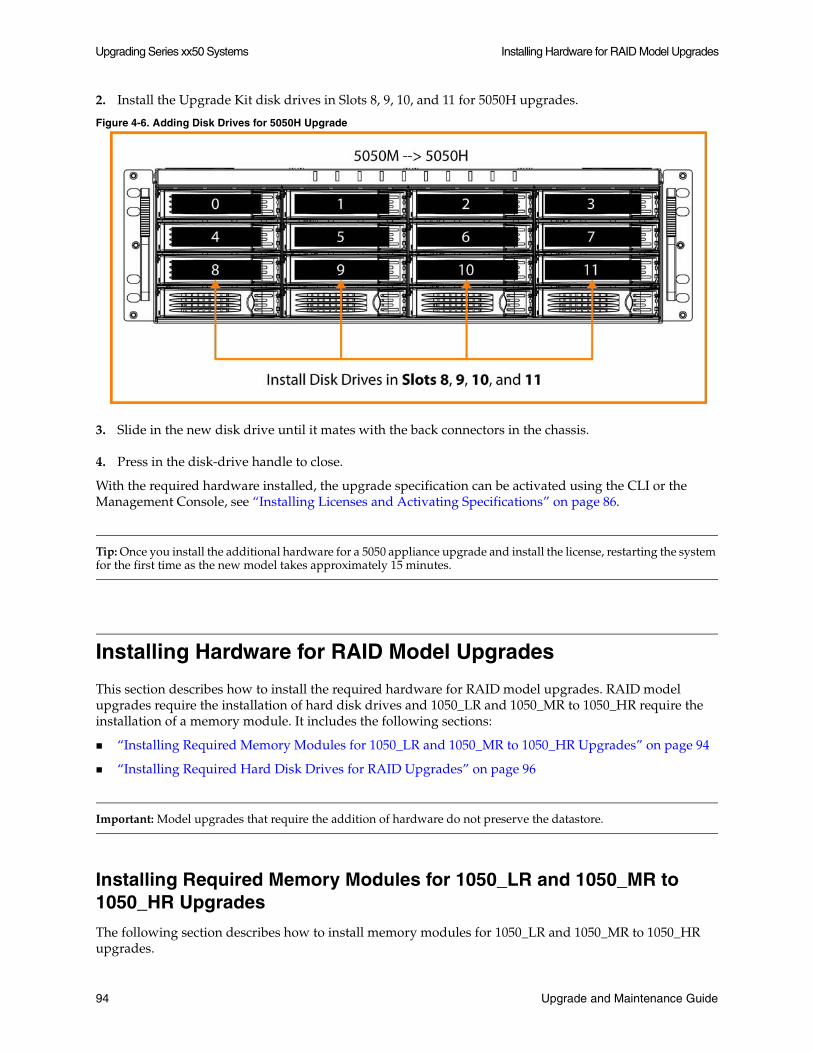
Upgrading Series xx50 Systems Installing Hardware for RAID Model Upgrades
2. Install the Upgrade Kit disk drives in Slots 8, 9, 10, and 11 for 5050H upgrades.
Figure 4-6. Adding Disk Drives for 5050H Upgrade
3. Slide in the new disk drive until it mates with the back connectors in the chassis.
4. Press in the disk-drive handle to close.
With the required hardware installed, the upgrade specification can be activated using the CLI or the Management Console, see “Installing Licenses and Activating Specifications” on page 86.
Tip: Once you install the additional hardware for a 5050 appliance upgrade and install the license, restarting the system for the first time as the new model takes approximately 15 minutes.
Installing Hardware for RAID Model Upgrades
This section describes how to install the required hardware for RAID model upgrades. RAID model upgrades require the installation of hard disk drives and 1050_LR and 1050_MR to 1050_HR require the installation of a memory module. It includes the following sections:
“Installing Required Memory Modules for 1050_LR and 1050_MR to 1050_HR Upgrades” on page 94
“Installing Required Hard Disk Drives for RAID Upgrades” on page 96
Important: Model upgrades that require the addition of hardware do not preserve the datastore.
Installing Required Memory Modules for 1050_LR and 1050_MR to 1050_HR Upgrades
The following section describes how to install memory modules for 1050_LR and 1050_MR to 1050_HR upgrades.
94 Upgrade and Maintenance Guide
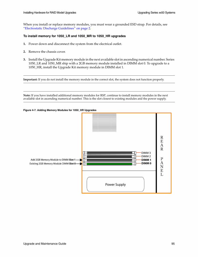
Installing Hardware for RAID Model Upgrades Upgrading Series xx50 Systems
When you install or replace memory modules, you must wear a grounded ESD strap. For details, see “Electrostatic Discharge Guidelines” on page 2.
To install memory for 1050_LR and 1050_MR to 1050_HR upgrades
1. Power down and disconnect the system from the electrical outlet.
2. Remove the chassis cover.
3. Install the Upgrade Kit memory module in the next available slot in ascending numerical number. Series 1050_LR and 1050_MR ship with a 2GB memory module installed in DIMM slot 0. To upgrade to a 1050_HR, install the Upgrade Kit memory module in DIMM slot 1.
Important: If you do not install the memory module in the correct slot, the system does not function properly.
Note: If you have installed additional memory modules for RSP, continue to install memory modules in the next available slot in ascending numerical number. This is the slot closest to existing modules and the power supply.
Figure 4-7. Adding Memory Modules for 1050_HR Upgrades
Upgrade and Maintenance Guide 95
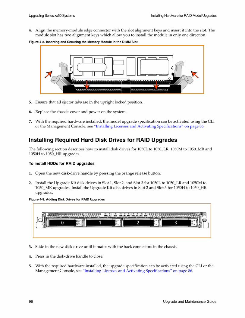
Upgrading Series xx50 Systems Installing Hardware for RAID Model Upgrades
4. Align the memory-module edge connector with the slot alignment keys and insert it into the slot. The module slot has two alignment keys which allow you to install the module in only one direction.
Figure 4-8. Inserting and Securing the Memory Module in the DIMM Slot
5. Ensure that all ejector tabs are in the upright locked position.
6. Replace the chassis cover and power on the system.
7. With the required hardware installed, the model upgrade specification can be activated using the CLI or the Management Console, see “Installing Licenses and Activating Specifications” on page 86.
Installing Required Hard Disk Drives for RAID Upgrades
The following section describes how to install disk drives for 1050L to 1050_LR, 1050M to 1050_MR and 1050H to 1050_HR upgrades.
To install HDDs for RAID upgrades
1. Open the new disk-drive handle by pressing the orange release button.
2. Install the Upgrade Kit disk drives in Slot 1, Slot 2, and Slot 3 for 1050L to 1050_LR and 1050M to 1050_MR upgrades. Install the Upgrade Kit disk drives in Slot 2 and Slot 3 for 1050H to 1050_HR upgrades.
Figure 4-9. Adding Disk Drives for RAID Upgrades
3. Slide in the new disk drive until it mates with the back connectors in the chassis.
4. Press in the disk-drive handle to close.
5. With the required hardware installed, the upgrade specification can be activated using the CLI or the Management Console, see “Installing Licenses and Activating Specifications” on page 86.
96 Upgrade and Maintenance Guide
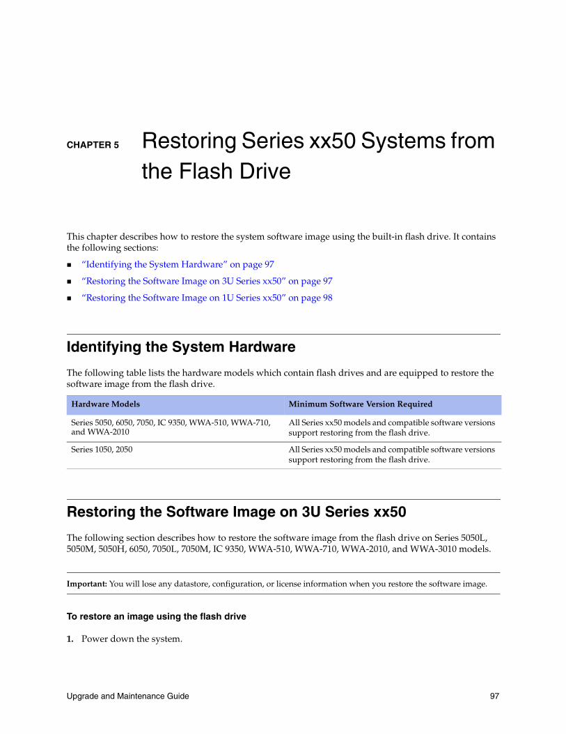
CHAPTER 5 Restoring Series xx50 Systems from the Flash Drive
This chapter describes how to restore the system software image using the built-in flash drive. It contains the following sections:
“Identifying the System Hardware” on page 97
“Restoring the Software Image on 3U Series xx50” on page 97
“Restoring the Software Image on 1U Series xx50” on page 98
Identifying the System Hardware
The following table lists the hardware models which contain flash drives and are equipped to restore the software image from the flash drive.
Restoring the Software Image on 3U Series xx50
The following section describes how to restore the software image from the flash drive on Series 5050L, 5050M, 5050H, 6050, 7050L, 7050M, IC 9350, WWA-510, WWA-710, WWA-2010, and WWA-3010 models.
Important: You will lose any datastore, configuration, or license information when you restore the software image.
To restore an image using the flash drive
1. Power down the system.
Hardware Models Minimum Software Version Required
Series 5050, 6050, 7050, IC 9350, WWA-510, WWA-710, and WWA-2010
All Series xx50 models and compatible software versions support restoring from the flash drive.
Series 1050, 2050 All Series xx50 models and compatible software versions support restoring from the flash drive.
Upgrade and Maintenance Guide 97
Restoring Series xx50 Systems from the Flash Drive Restoring the Software Image on 1U Series xx50
2. Connect a serial console or monitor and keyboard using the connectors on the back of the system. (Use the Console port to connect a monitor to the system.)
3. Power on the system.
4. If the appliance prompts Press any key to continue, press the space bar two times.
5. A menu appears with the following options:
0: Riverbed Steelhead Software v. 5.5.7 (64 bit)
1: Riverbed Steelhead Software v. 5.5.10 (64 bit)
6. Use the ^ and v keys to select highlight an entry. Press Enter to boot the selected OS, type the letter E to edit the commands before booting, the letter A to modify the kernel arguments before booting, or the letter C for a command line.
7. When prompted to install licenses, type N for no.
Note: You must install licenses from the Management Console or the CLI.
The system reboots.
Restoring the Software Image on 1U Series xx50
The following section describes how to restore the software image from the flash drive on Series 1050U, 1050L, 1050M, 1050H, 2050L, 2050M, and 2050H models.
Important: You will lose any datastore, configuration, or license information when you restore the software image.
To restore an image using the flash drive
1. Power down the system.
2. Connect a serial console or monitor and keyboard using the connectors on the back of the system. (Use the Console port to connect a monitor to the system.)
3. Power on the system.
4. If the machine prompts Press any key to continue, press the space bar two times.
5. A menu appears with the following options:
0: Riverbed Steelhead Software v. 5.5.7 (64 bit)
1: Riverbed Steelhead Software v. 5.5.10 (64 bit)
98 Upgrade and Maintenance Guide

Restoring the Software Image on 1U Series xx50 Restoring Series xx50 Systems from the Flash Drive
6. Use the ^ and v keys to select highlight an entry. Press Enter to boot the selected OS, type the letter e to edit the commands before booting, the letter a to modify the kernel arguments before booting, or the letter c for a command line.
7. When prompted to install licenses, type N for no.
You must install licenses from the Management Console or the CLI.
The system reboots.
Upgrade and Maintenance Guide 99

Restoring Series xx50 Systems from the Flash Drive Restoring the Software Image on 1U Series xx50
100 Upgrade and Maintenance Guide