Embed Size (px)
Citation preview
NUMBER
AA·5 SERIES MAINTENANCE MANUAL
CHAPTER 61
PROPELLER
TABLE OF CONTENTS
61-0 PROPELLER
Description/Operation
General
AA·5 and AA-5A Propeller
AA-5B Propeller
61-1-1 PROPELLER ASSEMBLY
Description/Operation
General
Maintenance Practices
Servicing
Propeller Removal/Installation
Inspection/ Check
Cleaning/Painting
Approved Repairs
PAGE
1
1
1
1
1
1
201
201
201
204
206
207
61 Page 1
January 4/80

I
AA-5 SERIES
MAINTENANCE MANUAL
PROPELLER - DESCRIPTION/OPERATION
1. General
A. AA-5 and AA-5A Propeller
The AA-5 and AA·5A aircraft are equipped with a two blade, fixed-pitch, aluminum alloy propeller, manufactured by McCauley Accessory Division . Part numbers for the propeller are as follows: If an aluminum spacer is used, the part number is 1C172/BTM·7359. If a steel spacer is used, the part number is 1C172/SBTM-7359.
B. AA-58 Propeller
The AA-58 aircraft is equipped with a two blade, fixed-pitch , aluminum alloy propeller, manufactured by McCauley Accessory Division, the part number is 1A170/FFA 7563, 1A170/KFA 7563, or 1A170E/KFA 7563.
© 1983 Gulfstream Aerospace Corporation 61·0
Page 1 June 1, 1983

1.
I General
AA-5 SERIES
MAINTENANCE MANUAL
PROPELLER ASSEMBLY - DESCRIPTION/OPERATION
The propeller assembly consists of the propeller, spacer, the spinner, and attaching hardware. The spinner assembly consists of a formed aluminum spinner, an aluminum support bulkhead assembly to which it is secured by screws and washers.
CAUTION: DO NOT MOVE THE AIRCRAFT ON THE GROUND BY PUSHING ON THE SPINNER.
STORE THE AIRCRAFT WITH THE PROPELLER IN THE VERTICAL POSITION TO PREVENT WATER ACCUMULATION IN THE SPINNER AND SUBSEQUENTLY FREEZING IN COLD WEATHER.
DO NOT OPERATE THE ENGINE WITH ICE IN THE SPINNER.
61-1-1 Page 1
July 15/78

1.
I 2.
I
I
I
I
Servicing
AA-5 SERIES MAINTENANCE MANUAL
PROPELLER ASSEMBLY - MAINTENANCE PRACTICES
Keep the propeller clean and free from stains or foreign matter. Continued propeller care will aid in preventing corrosion, especially in coastal regions. Refer to paragraph 4, this section, for cleaning procedure and materials.
Propeller Removal/Installation
A. Propeller Removal - AA5-0001 and subsequent, AA5A-0001 through 0829, AA5B-0001through1047 (See Figure 201.) For Aircraft within these serial number sequences having Service Kit 143 installed refer to paragraph 2C below.
(1) Remove screws (1) from spinner (2) and slide spinner forward off of propeller.
(2) Remove forward bulkhead (3) and shims (4) from spinner.
(3) Cut safety wire (5 ). Remove bolts (6) and washers (7).
( 4) Pull propeller ( 8) forward to remove from aircraft.
NOTE: When the propeller (8) is removed, the spacer (9) backplate assembly (10) and dowels (11) will rerr.ain attached to it.
CAUTION: WHEN REMOVING SPACER, ENSURE THAT PROPELLER IS SUPPORTED AS CLOSE TO BACKPLATE ASSEMBLY AS POSSIBLE. SUPPORTING IT NEAR THE TIPS MAY RESULT IN DAMAGE.
(5) Place the propeller on two padded supports, with the spacer (9) down.
(6) Use a soft metal 3/8-inch drift punch to drive the dowel pins (11) from the propeller (8).
(7) Remove backplate assembly (10) from spacer (9).
B. Propeller Installation - AA5-0001 and subsequent, AA5A-0001 through 0829, AA5B-0001through1047 (See Figure 201.) For Aircraft within these serial number sequences having Service Kit 143 installed refer to paragraph 2D below.
(1) Place backplate assembly (10) over dowel pins (11) in spacer (9).
NOTE: Propeller and spacer are matched during manufacturing. Align propeller serial No. stamped on spacer with No. 1 propeller blade for best balance. Propeller blade No. 1 can be identified by "#1" stamped on blade.
(2) Place propeller (8) on backplate assembly (10) so that the dowel holes in the propeller (8) are aligned with the dowel pins (11). Ensure that the bolt holes in the propeller (8) are aligned with the dowel pins (11). Ensure that the propeller (8) and backplate (10) are aligned with the bolt holes in the spacer (9).
(3) Place a padded wooden block on the propeller hub, and lightly tap the block with a hammer to seat the dowel pins in the propeller.
WARNING: ENSURE THAT THE MAGNETO SWITCH IS SET TO OFF AND THE MIXTURE IS SET TO IDLE CUTOFF PRIOR TO ROTATING THE CRANKSHAFT.
( 4) Rotate the engine crankshaft until the TC mark on the starter gear is aligned with the parting line on the engine crankcase .
(5) On AA-5B aircraft, position the propeller by rotating the crankshaft until the top center (TC) mark on the starter gear and the crankcase parting flange or the index on the starter housing are aligned, then install propeller at the one and seven o'clock position.
On AA-5 and AA-5A aircraft position the propeller with the spacer against the engine, and the No. 1 blade of the propeller at the ten o'clock position. Ensure that the bolt holes in the spacer align with the bolt holes in the engine.
(6) Install the six propeller bolts (6) and washers (7). Torque as follows: for AA-5 and AA-5A aircraft, 540 inch-pounds. For AA-5B aircraft, 750.±.30 inch-pounds.
(7) Safety wire bolts, (6), in pairs, with 0.041 inch minimum diameter safety wire (5).
61-1-1 Page .201
January 4/80 Provided by the AYA - www.aya.org as a se'V1ce to ts Members ror ti--e latest vers O'"' or pronted copies of this marual co..,tact rletcher Av at:o'"' 0'"' (800) 3

6
AA-5 SERIES MAINTENANCE MANUAL
11
4
10 1. SCREW 2. SPINNER 3. BULKHEAD 4. SHIM 5. SAFETY WIRE 6. BOLT 7. WASHER 8. PROPELLER
AA5-0001 AND SUBSEQUENT WITH OUT SERVICE KIT 143 AA5A-0001 THROUGH 0829 WITH OUT SERVICE KIT 143 AA5B-0001 THROUGH 1047 WITH OUT SERVICE KIT 143
9. SPACER 10. BACKPLATE ASSY. 11. DOWEL PIN
11
10
1. SPINNER 2. SCREW 3. WASHER 4. BOLT 5. DOUBLER 6. FORWARD BULKHEAD ASSEMBLY 7. PROPELLER 8. DOWEL PIN 9. SPACER
AASA-0830 AND SUBSEQUENT AA5B-1048 AND SUBSEQUENT AA5-0001 AND SUBSEQUENT 10. AFT BULKHEAD ASSEMBLY
WITH SERVICE KIT 143 AA5A-0001 THROUGH 0829
WITH SERVICE KIT 143 AASB-0001 THROUGH 1047
WITH SERVICE KIT 143
11. STARTER RING GEAR
Propeller Removal/Installation Figure 201
~
Provided by tre AYA - www.aya.org as a serv ce to its fVlerrbers f-or the latest version or printed coo1es of trrs rranual contact Fletcher Aviation on (
61-1-1 Page 202
January 4/80

AA·S SERIES MAINTENANCE MANUAL
(8) Place shims (4) on bulkhead (3) and insert rear of bulkhead (3) into propeller (8). Install spinner (2) and check alignment of screw holes in spinner (2) and backplate assembly (10). Add or remove shims (up to a maximum of 6) to obtain a pr'eloading of 0.10 inch. Proper preloading occurs when the holes in the spinner are approximately 112 hole-width forward of those in the backplate assembly.
(9) Push spinner (2) until holes align, then secure spinner (2) to backplate (10) with screws (1). Tighten screws in sequence listed in Figure 202.
C. Propeller Removal· AA5A-0830 and subsequent, AA5B-1048 and subsequent (See Figure 201.) Also for Aircraft within the following serial number sequences having Service Kit 143 installed: AA5-0001 and subsequent, AA5A-0001 through 0829, AA5B-0001 through 104 7.
(1) Prepare a suitable padded support for the propeller. The propeller should be supported as close to the hub as possible.
CAU'.l'ION: SUPPORTING THE PROPELLER NEAR THE TIPS MAY RESULT IN DAMAGE.
(2) Prepare the airplane for safe maintenance. Place the MASTER and MAGNETO switches in the OFF Position . Make sure the airplane is grounded. Set the mixture control to the idle cutoff position .
CAUTION: WHEN WORKING WITH THE PROPELLER, ALWAYS TREAT IT AS THOUGH THE MAGNETO WERE ON. STAND CLEAR IF IT IS NECESSARY TO ROTATE THE PROPELLER FOR ANY REASON. A FAULTY GROUND ON EITHER MAGNETO CAN CAUSE THE ENGINE TO FIRE.
(3) Remove screws (2) and washers (3) securing spinner (1) to forward bulkhead assembly (6) and aft bulkhead assembly (10). Remove spinner (1) by sliding forward off of propeller.
(4) Remove safety wire from bolts (4). Provide support for propeller (7) and remove bolts (4) doubler (5) and forward bulkhead (6). Move propeller to padded supports with spacer (9) down.
(5) Using a fiber or soft metal 3/8 inch drift punch, drive the dowel pins (8) from the propeller (7). Remove spacer (9), and aft bulkhead assembly (10).
D. Propeller Installation· AA5A-0830 and subsequent, AA5B-1048 and subsequent (See Figure 201.) Also for aircraft within the following serial number sequences having Service Kit143 installed: AA5-0001 and subsequent, AA5A-0001 through 0829, AA5B-0001 through 104 7.
NOTE: Propeller (7) and spacers (9) are provided by the manufacture in matched pairs identified with the same serial number and should not be intermixed. For best balance, aligh the serial number on the spacer with the propeller blade stamped #1.
(1) Install the dowel pins (8) in the dowel holes in the spacer (9). Position the propeller (7) so that the #1 blade corresponds to the position of the serial number on the spacer and start the dowel pins into the dowel holes in the propeller.
(2) With the propeller secure on the padded support, place a padded wooden block on the propeller hub. Lightly tap the block with a hammer to seat the dowel pins in the propeller.
( 3) Install aft bulkhead assembly (10) on starter ring gear (11) and use a temporary method of securing the bulkhead in place. (One temporary method is to tape the bulkhead to the nose cowl.)
CAUTION: THE AFT BULKHEAD CAN BE DAMAGED IF NOT HELD SECURELY IN PLACE DURING PROPELLER INSTALLATION. REMOVE TEMPORARY SECURING MATERIAL AFTER PROPELLER MOUNT BOLTS ARE TORQUED.
(4) Position Forward bulkhead assembly (6) and doubler (5) on propeller (7) and insert propeller mount bolts (4) through the doubler, bulkhead, propeller, and spacer. Install this assembly on the starter ring gear (11).
NOTE: Do not use any washers on bolts ( 4).
(5) Install propeller mount bolts (4) into starter ring gear (11) and torque the bolts to the following values:
AA-5/AA-5A AA-5B
45 LB.FT./40 LB.FT. (540 LB.IN./480 LB.IN.) 65 LB.FT./55 LB.FT. (780 LB.IN./660 LB.IN.)
Safety wire propeller mount bolts in pairs.
Provided by tre AYA - www.aya.org as a serv ce to its fVlerrbers f-or the latest version or printed coo1es of ths rranual contact Fletcher Aviation on (800) •
fil-1-1 Page 203
January 4/80

AA·S SERIES MAINTENANCE MANUAL
(6) Install the spinner (1) over the propeller (7) and align with holes in forward bulkhead assembly (6) and aft bulkhead assembly (10). Install washers ( 3) and screws (2).
NOTE: Use only washers conforming to Federal Specification NAS1515J3L. Do not use metal washers of any kind.
NOTE: Install all screws and washers before beginning the tightening sequence.
(7) Tighten the screws to standard torque (Chapter 91) using the sequence shown in Figure 202. Repeat the sequence to correct any torque loss due to compression of the nonmetallic washers.
3. Ins{>E!ction/Check
A. Propeller Inspection
(1) Include the propeller in every preflight inspection. The propeller should receive special attention for condition during 50 and 100 hour inspections. Visually inspect the entire propeller for damage and defects. Any necessary repairs should be made before further flight, and should strictly adhere to AC43.13-1, "Aircraft Inspection and Repair Manual," and service publications of the propeller manufacturer.
(2) Remove the spinner at each 100 hour inspection. (Refer to paragraph 3B, below, for spinner inspection) After inspection, necessary repairs and reinstallation of spinner, check the spinner run-out. Maximum allowable run-out measured at the tip of the spinner is:
AA5-0001 and subsequent without service kit 143 (0.010 inch) AA5-0001 and subsequent with service kit 143 (0.025 inch) AA5A-0001 through 0829 without service kit 143 (0.010 inch) AA5A-0001 through 0829 with service kit 143 (0.025 inch) AA5B-0001 through 1047 without service kit 143 (0.010 inch) AA5B-0001 through 1047 with service kit 143 (0.025 inch) AA5A-0830 and subsequent (0.025 inch) AA5B-1048 and subsequent (0.025 inch)
(3) Some of the types of damage and defects which may be observed are defined as follows:
Burr-
Corrosion -
Crack -
Cut-
Dent-
Erosion -
Fretting-
Gouge -
Inclusion -
Nick
Pitting-
Scratch -
Score -
A small , thin section of metal extending beyond a regular surface, usually located at a comer or on the edge of a bore or hole .
Loss of metal from the surface by chemical or electrochemical action. The corrosion products generally are easily removed by mechanical means. Iron rust is an example of corrosion.
A physical separation of two adjacent portions of metal, evidenced by a fine or thin line across the surface, caused by excessive stress at that point. It may extend inward from the surface, from a few thousandths of an inch to completely through the section thickness.
Loss of metal, usually to an appreciable depth over a relatively long and narrow area, by mechanical means, as would occur with the use of a saw blade, chisel, or sharp-€dged stone striking a glancing blow.
Indentation in a metal surface produced by an object striking with force . The surface surrounding the indentation will usually be slightly upset.
Loss of metal from the surface by mechanical action of foreign objects, such as grit or fine sand. The eroded area will be rough and may be lined in the direction in which the foreign material moved relative to the surface.
Breakdown or deterioration of metal surface by vibratory or "chattering" action. Usually no loss of metal or cracking of surface but generally showing similar appearance.
Grooves in, or breakdown of, metal surface from contact of foreign material under heavy pressure. Usually indicates metal loss but may be largely displacement of material.
Presence of foreign or extraneous material wholly within a portion of metal. Such material is introduced during the manufacture of rod, bar, or tubing by rolling or forging.
Local break or notch on edge. Usually displacement of metal rather than loss.
Sharp, localized breakdown (small, deep cavity) of metal surface, usually with defined edges.
Slight tear or break in metal surface from light, momentary contact by foreign material.
Deeper (than scratch) tear or break in metal surface from contact under pressure. May show discoloration from temperature produced by friction.
Prov ded by the A YA www.aya erg as a service to its F"or the I· test version or printed copies of this manual cont ct Fletcher/.
" ers ion (
61-1-1 PaJ.?e 204
January 4/80

4-
AA-5 SERIES MAINTENANCE MANUAL
1
i
2
5
..--3
AA5-0001 AND SUBSEQUENT WITHOUT SERVICE KIT 143 AA5A-0001 THROUGH 0829 WITHOUT SERVICE KIT 143 AA58-0001THROUGH1047 WITHOUT SERVICE KIT 143
9 13
12
8 .............
14 t 10
AA5A-0830 AND SUBSEQUENT AA5B-1048 AND SUBSEQUENT AA5-0001 AND SUBSEQUENT WITH SERVICE KIT 143 AA5A-0001 THROUGH0829 WITH SERVICE KIT 143 AA58-0001 THROUGH 1047 WITH SERVICE KIT 143
Spinner Screw Tightening Sequence Figure 202
Provided by t'"'e AYA www.aya erg as a serv ce .o its l\f errbers for the latest version or printed copies of this manual contact Hetcher Aviation on (800)
61-1-1 Page 205
January 4/80
I
I
AA·5 SERIES MAINTENANCE MANUAL
Stain - A change in color, locally, causing a noticeably different appearance from the surrounding area.
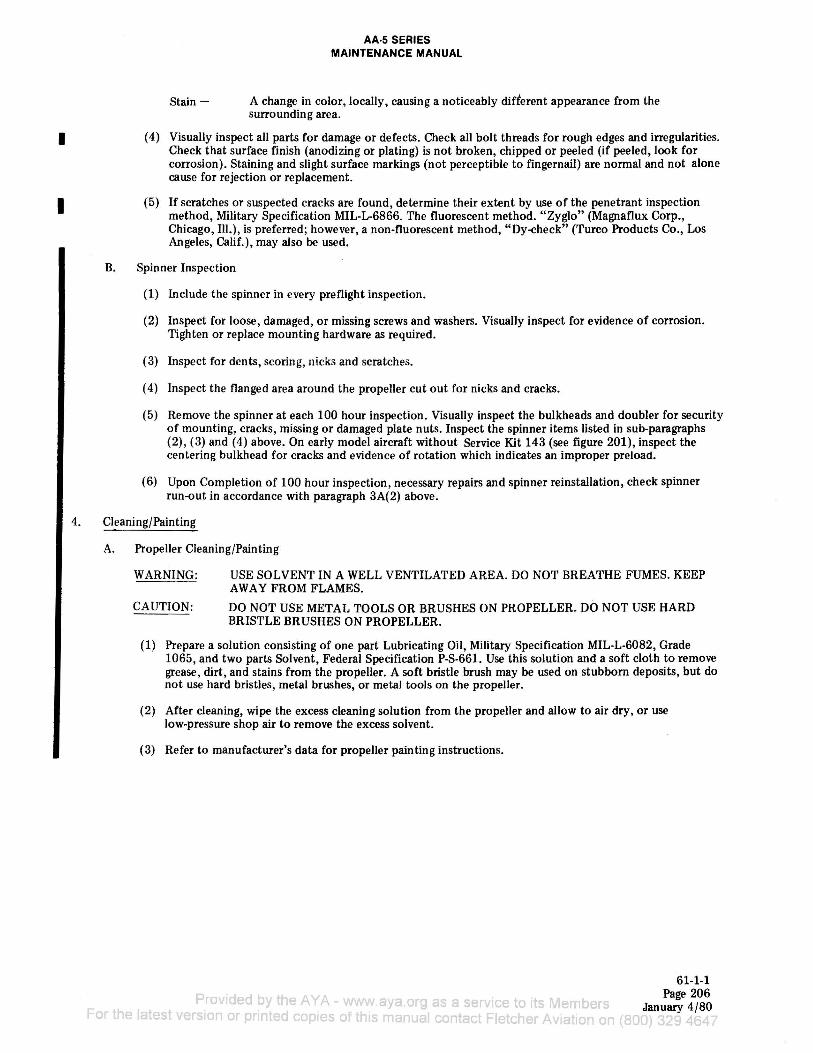
( 4) Visually inspect all parts for damage or defects. Check all bolt threads for rough edges and irregularities. Check that surface finish (anodizing or plating) is not broken, chipped or peeled (if peeled, look for corrosion). Staining and slight surface markings (not perceptible to fingernail) are normal and not alone cause for rejection or replacement.
(5) If scratches or suspected cracks are found, determine their extent by use of the penetrant inspection method, Military Specification MIL-L-6866. The fluorescent method. "Zyglo" (Magnaflux Corp., Chicago, Ill.), is preferred; however, a non-fluorescent method, "Dy~heck" (Turco Products Co., Los Angeles, Calif.), may also be used.
B. Spinner Inspection
(1) Include the spinner in every preflight inspection.
(2) Inspect for loose, damaged, or missing screws and washers. Visually inspect for evidence of corrosion. Tighten or replace mounting hardware as required.
(3) Inspect for dents, scoring, nicks and scratches.
( 4) Inspect the flanged area around the propeller cut out for nicks and cracks.
(5) Remove the spinner at each 100 hour inspection. Visually inspect the bulkheads and doubler for security of mounting, cracks, missing or damaged plate nuts. Inspect the spinner items listed in sub-paragraphs (2), (3) and (4) above. On early model aircraft without Service Kit 143 (see figure 201), inspect the centering bulkhead for cracks and evidence of rotation which indicates an improper preload.
(6) Upon Completion of 100 hour inspection, necessary repairs and spinner reinstallation, check spinner run-out in accordance with paragraph 3A(2) above.
4. Cleaning/Painting
A. Propeller Cleaning/Painting
WARNING:
CAUTION:
USE SOLVENT IN A WELL VENTILATED AREA. DO NOT BREATHE FUMES. KEEP AWAY FROM FLAMES.
DO NOT USE METAL TOOLS OR BRUSHES ON PROPELLER. DO NOT USE HARD BRISTLE BRUSHES ON PROPELLER.
(1) Prepare a solution consisting of one part Lubricating Oil, Military Specification MIL-L-6082, Grade 1065, and two parts Solvent, Federal Specification P-S-661. Use this solution and a soft cloth to remove grease, dirt, and stains from the propeller. A soft bristle brush may be used on stubborn deposits, but do not use hard bristles , metal brushes, or metal tools on the propeller.
(2) After cleaning, wipe the excess cleaning solution from the propeller and allow to air dry, or use low-pressure shop air to remove the excess solvent.
(3) Refer to manufacturer's data for propeller painting instructions.
F rov1ded by the A YA www., ya.erg as a service to its Members for+ e latest verso,.. or pr-nted copies of this marual co,..tac• Fletcher Av at o" O" (
61-1-1 Page 206
January 4/80

B. Spinner Cleaning/Painting
AA·5 SERIES MAINTENANCE MANUAL
I (1) Refer to Chapter 20 for spinner cleaning and painting procedures.
I
5. Approved Repairs
A.
B.
Propeller Repair
(1) Repair the propeller in accordance with AC 43.13-1, Aircraft Inspection and Repair Manual or manual and bulletins published by the propeller manufacturer.
Spinner Assembly Repair
(1) Spinner and components repair consists of replacement of missing or loose attachment hardware (screws md nutplates ). If the spinner is warped or dented it should be replaced.
(2) Polish out nicks, scratches, and scoring.
(3) Determine the extent of cracks or suspected areas as described in paragraph 3A(5) above. Cracks may be repaired by welding. Do not attempt repair if crack extends into a mounting hole.
Provided by the AYA - www.aya.org as a service to its Members For the latest version or printed copies of this manual contact Fletcher Aviation on (800)
61-1-1 Page 207
Jan ua1y 4 / 80