Embed Size (px)
Citation preview

EIB3024 / 3016 / 3014AlarmsInstruction Manual
Mains Powered
Read and retain carefully for as long as the product is being used. It contains vital information on the operation and installation of your Alarm. The leaflet should be regarded as part of the product.
If you are just installing the unit, the leaflet MUST be given to the householder. The leaflet is to be given to any subsequent user.

2

3
Contents
Installer Guide 5
1. Introduction 5
1.1 Overview 7 1.2 Technical Specifications 9
2. Installation 11
2.1 Important Safety Instructions 12
2.2 Where to locate the Alarm? 13
2.3 Which Alarm in what room? 17
2.4 Where in the room? 18
2.5 Locations to avoid 20
2.6 Mounting and wiring 22
2.7 Interconnecting Alarms 26 2.8 Removing the Alarm 28

4
User Guide 29
3. Testing 29
3.1 Testing and maintaining your Alarm 30 3.2 Cleaning your Alarm 32
4. What to do in case of alarm 34
5. Troubleshooting and Indicator summary tables 36
6. Important safeguards 44
7. Service and Guarantee 47
7.1 Getting your Alarm serviced 48 7.2 Guarantee 48

5
1Introduction
Installer Guide

6
The EIB3024 is a Multi-Sensor Alarm with heat enhanced photoelectric smoke sensor and automatic dust compensation, delivering a faster response to a wider range of fires. It detects both smoke and heat from a fire and is ideal for hallway, landing, living room and bedroom areas.
The EIB3016 is an Photoelectric Smoke Alarm, with a proven optical sensor and automatic dust compensation delivering a fast response to smouldering fires. It is ideal for hallway, landing and living room areas.The EIB3014 is a Heat Alarm with a Class A1 heat sensor. It can only to be used as part of a an interconnected alarm system, i.e. interconnected with Brooks mains powered Multi-Sensor or Smoke Alarms. It is ideal for kitchens, garages, boiler houses and other areas where there are normally high levels of fumes, smoke or dust i.e. places where Multi-Sensor or Smoke Alarms cannot be installed without the risk of excessive nuisance alarms.
Up to 12 Alarms can be interconnected so that if one senses fire, all Alarms sound. It can be a hardwired interconnection, a wireless interconnection or a mixture of both (for the wireless option an EIB3000MRF SmartLINK module needs to be added to each Alarm – sold separately).
The EIB3000 series is supplied with a mounting plate that allows very quick and simple installation of the Alarm. The mains and battery power is automatically connected as the Alarm slides onto the mounting plate. Each Alarm comes with built-in rechargeable backup batteries to power the Alarm in the event of a mains failure.
AudioLINKThe EIB3000 series Alarms are AudioLINK enabled. This feature allows the user to download information from the Alarm through the use of a mobile App. For more information on using this feature, please refer to the relevant section on www.eielectronics.com or www.brooks.com.au

7
1.1 Overview
Red LEDAlarm Indicator
Yellow LEDFault Indicator
Green LEDPower Indicator
Test / Hush Button Alarm Sounder
EIB3014 Heat AlarmEIB3016 Photoelectric Alarm
Heat Sensor(Thermistor)
RF ModuleLED Indicator
RF ModuleLearn Switch
AlarmRemovalLatch
Smoke EntryVents
RF ModuleLED Indicator
RF ModuleLearn Switch
AlarmRemovalLatch
Heat Sensor(Thermistor)
Smoke EntryVents
RF ModuleLED Indicator
RF ModuleLearn Switch
AlarmRemovalLatch
EIB3024 Multi-Sensor Alarm

8
Red LEDAlarm Indicator
Yellow LEDFault Indicator
Green LEDPower Indicator
Test / Hush Button Alarm Sounder
EIB3014 Heat AlarmEIB3016 Photoelectric Alarm
Heat Sensor(Thermistor)
RF ModuleLED Indicator
RF ModuleLearn Switch
AlarmRemovalLatch
Smoke EntryVents
RF ModuleLED Indicator
RF ModuleLearn Switch
AlarmRemovalLatch
Heat Sensor(Thermistor)
Smoke EntryVents
RF ModuleLED Indicator
RF ModuleLearn Switch
AlarmRemovalLatch
EIB3024 Multi-Sensor Alarm

9
Smoke Sensor Photoelectric (EIB3024 and EIB3016)
Heat Sensor Thermistor Class A1 (EIB3014 and EIB3024)
Power Supply 230V AC, 50Hz, 0.25W
Battery BackupBuilt-in 10-year rechargeable Vanadium Pentoxide Lithium cells. Fully charged, the battery will provide up to 6 months (without module fitted) or 3 months (with module fitted) back-up without mains power
Alarm Sounder Piezoelectric Horn
Alarm Sound Level 85dB(A) at 3 meters (min)
Memory Feature Indicates that the Alarm has previously detected fire
Self Test Sensors, batteries and electronics are automatically tested periodically
Test/Hush ButtonChecks sensors, electronics, interconnection and sounder. If the unit is in alarm when pressed, it silences the alarm for 10min
Visual indicatorsGreen LED – Power supply Yellow LED – Fault, EOLRed LED – Memory or alarm (if coincides with horn sounding)
AudioLINK Enabled
Operational Life 10 years
1.2 Technical Specifications

10
InterconnectionUp to 12 units can be interconnected via a hardwired or wireless system (using optional EIB3000MRF SmartLINK module)
FixingsSupplied with Easi-fit anti-tamper mounting plate with integral terminal block and wiring cover, includes screws and wall plugs
Operating Temperature Normal: -10°C to +40°C (Storage: -10°C to +40°C) *
Humidity Range 15% to 95% RH (non-condensing)
Plastic Material UL94V-0 flame retardant rated
Dimensions
EIB3024 and EIB3014: Product: - Ø150mm x 66mm Package - 155mm x 155mm x 70mm EIB3016: Product: - Ø150mm x 63mm Package - 155mm x 155mm x 65mm
Weight 350g (including packaging)
Warranty 5 year (limited)
Approvals Conforms to AS3786:2014 and AS1603.3:2018
* Temperature and Humidity conditions are for normal operation and storage. Units will function outside these ranges as required by the specific product Standards. Extended exposure to conditions outside these ranges can reduce product life. For advice on prolonged operation outside these ranges consult the manufacturer.

11
2Installation

12
2.1 Important Safety InstructionsMains operated Alarms should be installed and interconnected by a licensed electrician in accordance with the relevant Regulations for Electrical Installations. Failure to install this Alarm correctly may expose the user to shock or fire hazards and damage the product.
The Alarm is designed to be permanently mounted, using it’s own built-in terminal block to connect it to the mains. The mounting plate can be screwed directly to the ceiling. Alternatively it can be screwed to a junction box. The Alarm must not be exposed to dripping or splashing. There are important markings on the underside of the Alarm.
Alternative Energy Sources - (Wind, Solar, UPS etc.)This product is designed to be connected to a Pure or True Sine Wave 230V AC supply.If connecting to a power source that utilises an inverter, e.g. PV solar panel, the Total Harmonic Distortion (THD) must be less than 5%. If in doubt please check with the manufacturer of the inverter. This also applies to battery powered UPS (Uninterruptible Power Supply) inverters.
Light Dimmer Circuits – The Alarms must not be powered from a light dimmer circuit.
Do not install Alarms in new or renovated buildings until all work is completed.
The Alarm must not be connected when the house wiring insulation is being checked with high voltages. i.e. Do not use a high voltage insulation tester on the Alarm.

13
The Alarm must be continuously powered 24 hours a day so it is important that it is not on a circuit that can be turned off by a switch.
The power supply for the Alarms should be derived from the public electricity supply to the dwelling. The mains supply to the Alarms should take the form of either:(a) an independent circuit at the dwelling’s main distribution board, in which case no
other electrical equipment should be connected to this circuit (other than a dedicated monitoring device installed to indicate failure of the mains supply to the Alarms); or
(b) the non-switched side of a separately electrically protected, regularly used local lighting circuit. Alarms should be connected on a single final circuit, unless the means of interconnection is by radio signals (e.g. RadioLINK).
2.2 Where to locate the AlarmThe main reason for fitting Smoke/Heat/Multi-Sensor Alarms in dwellings is to ensure that when there is a fire, sufficient early warning is given so that everybody can escape safely. This means that the Alarms should ideally be located near all potential sources of fires and that the alarm should be heard throughout the house – particularly in the bedrooms.
It is also important that nuisance/false alarms are minimised to ensure the Alarms are not disabled or ignored.

14
A single Smoke Alarm will give some protection if it is properly installed, but most homes will require two or more to ensure that a reliable early warning is given. For recommended protection you should put individual Smoke Alarms in all rooms where fire is most likely to break out (apart from the kitchen and bathroom).
The Building Code of Australian, state and territory building regulation and AS1670.1 give the guidance on:- how many Alarms to install- what type of Alarm to use- where to position AlarmsThe above points will depend on the type of dwelling and class of building to be protected and the level of fire risk.
Fire Risk AssessmentThe type of system that should be installed depends on the fire risk. It is therefore recommended that a Fire Risk Assessment is undertaken. The Risk Assessment would be based on a combination of probabilities:- fire occurring- injury or death to occupant- system operating correctly with a fire- early detection and warning to occupants in the event of a fire.
The greater the risks, the more comprehensive and reliable systems needs to be.

15
Smoke Alarms located as across plus:
Bedroom
Bedroom
Bedroom
Bat
hroo
m
Bat
h
Dining Room
LaundryRoom
Living Room
Kitchen

16
Smoke Alarms located as across plus:
Bedroom
Bedroom
Bedroom
Bat
hroo
m
Bat
h
Dining Room
LaundryRoom
Living Room
Kitchen

17
2.3 Which Alarm in what room?
Location EIB3024Mutil-Sensor
Alarm
EIB3016PhotoelectricSmoke Alarm
EIB3014Heat
Alarm (i)
Hall, Corridors, Escape routes ✔ ✔ ✗
Kitchens / Garages ✗ ✗ ✔ (iii)
Living Rooms ✔ ✔ ✔ (ii)
Bedrooms ✔ ✔ ✗
Shower / Bathrooms ✗ ✗ ✗
(i) A Heat Alarm should only be used in a room adjoining an escape route, in conjunction with Multi-Sensor Alarms or Smoke Alarms on the escape routes. All the Alarms should be interconnected to ensure the early warning will be heard.
(ii) Where Heat Alarms replace a required Smoke Alarm due to an unacceptable level of nuisance alarms, Smoke Alarms must be installed in other locations within the dwelling to ensure effective early warning. Heat Alarms must be interconnected to installed Smoke or Multi Alarms.
(iii) In enclosed kitchens with doors closed.

18
2.4 Where in the room?The locations must comply with the Building Code of Australian, state and territory legislation and the instructions in this leaflet.
<600mmHEAT ALARMS
<150mm
SMOKE /MULTI-SENSOR
ALARMS
APEX
x x
300mm
300mm (min)
Ceiling MountingHot smoke rises and spreads out, so a central ceiling position is the preferred location. The air is “dead” and does not move in corners, therefore Alarms must be mounted away from corners. Fit the Alarm:- At least 300mm away from walls (see Figure 1).- At least 300mm from any light fitting or decorative object which might obstruct smoke / heat
entering the Alarm.
Fig.1

19
Fig.2500 mm
1500 mm max.
300 mm
min.
Ceiling line
Exposed �oor joists
Side Wall
DEAD AIRSPACE AND PROPER MOUNTING OF SMOKE ALARMS ON SIDE WALLS
300 mm
500 mm
max.
min.
Dead air spaceSuitable smokealarm location
Key:
Wall Mounting (EIB3016 only)If ceiling mounting is impractical, only the EIB3016 Photoelectric Smoke Alarm may be mounted on a wall, provided that:
a) the top of the detection element is between 300mm and 500mm below the ceiling (see Figure 2);
b) the bottom of the detection element is above the level of any door openings;
20
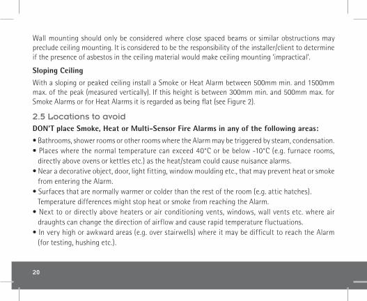
Wall mounting should only be considered where close spaced beams or similar obstructions may preclude ceiling mounting. It is considered to be the responsibility of the installer/client to determine if the presence of asbestos in the ceiling material would make ceiling mounting ‘impractical’.
Sloping Ceiling
With a sloping or peaked ceiling install a Smoke or Heat Alarm between 500mm min. and 1500mm max. of the peak (measured vertically). If this height is between 300mm min. and 500mm max. for Smoke Alarms or for Heat Alarms it is regarded as being flat (see Figure 2).
2.5 Locations to avoidDON’T place Smoke, Heat or Multi-Sensor Fire Alarms in any of the following areas:• Bathrooms, shower rooms or other rooms where the Alarm may be triggered by steam, condensation. • Places where the normal temperature can exceed 40°C or be below -10°C (e.g. furnace rooms,
directly above ovens or kettles etc.) as the heat/steam could cause nuisance alarms.• Near a decorative object, door, light fitting, window moulding etc., that may prevent heat or smoke
from entering the Alarm.• Surfaces that are normally warmer or colder than the rest of the room (e.g. attic hatches).
Temperature differences might stop heat or smoke from reaching the Alarm.• Next to or directly above heaters or air conditioning vents, windows, wall vents etc. where air
draughts can change the direction of airflow and cause rapid temperature fluctuations.• In very high or awkward areas (e.g. over stairwells) where it may be difficult to reach the Alarm
(for testing, hushing etc.).

21
• Locate away from very dusty or dirty areas as dust build-up on the optical smoke sensor can impair performance. It can block the insect screen mesh and prevent smoke from entering the sensor. Dust build up can also increase the response time of the heat sensor.
• Locate the Alarm at least 1m from dimmer controlled lights and wiring as some dimmers can cause interference.
• Locate the Alarm at least 1.5m and route wiring at least 1m away from fluorescent light fittings as electrical “noise” and/or flickering may affect the Alarm. Do not wire into the same circuit as fluorescent lights or dimmers.
• Do not locate in insect infested areas. Small insects getting into the optical smoke sensor can cause intermittent false alarms. Insects and contamination on the heat sensor can increase its response time.
• Do not locate in a damp or humid area.• Open air spaces such as undercrofts.
Do not locate Heat Alarms directly above a sink or cooker – Keep at least 1m horizontal distance between these items and the Alarm.

22
2.6 Mounting and wiring
Foam ceiling gasket(must be in place)
Insert screwdriverto lift and remove
wiring cover
Fig.3
1. Select a location complying with the advice in previous sections.
2. Disconnect the AC mains supply from the circuit that is going to be used.
3. Lift off the wiring cover as shown in Figure 3.
The wiring must be TPS 1.5mm2 and connected to the terminal block on the mounting plate as follows:
L: Live - connect to the house wires coloured brown or marked L.N: Neutral - connect to the house wires coloured blue or marked N.IC: Interconnect - see figures 5 and 6 and further information in Section 2.6.
Note: Wiring must be installed in compliance with AS3000.

23
Warning: Mixing (or leaving unattached) the Live and Neutral connections when interconnecting Alarms may damage all the Alarms - ensure that the same colour wires are used throughout the premises for Live, Neutral and Interconnect wires.
We strongly recommend that you check for the following before connecting the Alarm:• check for Live and Neutral using a two probe tester. • check for Live using a neon tester. • check that the Interconnect wire is NOT connected to Live, Neutral or Earth. Do not use an Earth
wire for the Interconnect line.Note: The Alarm does not need to be earthed. However the terminal marked is provided for the convenience of the installer so that any copper Earth wire or cable coloured green and yellow, can be safely terminated.
To interconnect Alarms connect all the IC terminals together as shown in Figure 8 (see Interconnecting Alarms section).

24
4. If the mains wires are recessed, bring the wires through the rear hole in the mounting plate as shown in Figure 4.
If the mains wires are being brought along the surface:(a) position the mounting plate so the cable trunking is as shown in Figure 4.(b) the mounting plate has a removable section, take it out to interface directly with 25mm trunking
as shown in Figure 5. If interfacing to 16mm trunking carefully cut around the marked section, leaving the top intact and replace the section. (If you are not using surface wiring, the removable section must be left in place for electrical safety reasons).
There are two other positions which are also suitable for the surface wiring to enter (and exit) the Alarm, one next to the removable section and another directly opposite.
5. Carefully align the mounting plate and screw into place. Connect the wires to the terminal block. With recessed wiring, ensure the rear gasket seals around the edge of the hole in the ceiling or
REMOVEABLETRUNKING DOOR FOR
Fig.4 Fig.5
25
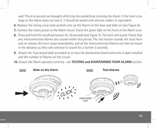
wall. This is to prevent air draughts affecting the smoke/heat entering the Alarm. If the hole is too large or the Alarm does not seal it, it should be sealed with silicone rubber or equivalent.
6. Replace the wiring cover and carefully line up the Alarm on the base and slide on (see Figure 6).
7. Connect the mains power to the Alarm circuit. Check the green light on the front of the Alarm is on.
8. Press and hold the test/hush button for 10 seconds (see Figure 7). The horn will sound. Check that any interconnected Alarms also sound within this period. The test button sounds the local horn and on release this horn stops immediately, and all the interconnected Alarms can then be heard in the distance as they will continue to sound for a further 3 seconds.
9. Attach the ’fuse board label’ provided on or near the distribution board and write in date installed and the number of Alarms on the circuit.
10. Ensure the Alarm operates correctly - see TESTING and MAINTAINING YOUR ALARM section.
Slide on the Alarm Test AlarmsFig.6 Fig.7

26
2.7 Interconnecting AlarmsWith interconnected Alarms, when one device detects Fire all detectors will alarm. All horns will sound but only Alarms detecting the emergency event will be flashing their red LED alarm indicator.
Heat Alarms should always be interconnected to Smoke or Multi-Sensor Fire Alarms to ensure early warning.Note: A maximum of 12 Fire / Smoke / Heat / CO Alarms and accessory devices can be interconnected in a Brooks Alarm system. (Any EIB3000 series Alarm can also be interconnected to an EIB160e and EIB140RC Series).
If you wish to connect more than 12 alarms, contact your regional office as shown in the end of this manual.
WARNING: Do not connect these Alarms to any other type of Brooks Alarm (apart from those listed above) or to any other model produced by another manufacturer. Doing so may damage the Alarms and could result in a shock or fire hazard.
Systems using more than 3 or 4 Alarms must be very carefully planned to ensure nuisance alarms are not excessive. e.g. from cooking fumes or steam. The following is suggested: • In an RF system a Brooks Control Switch (EIB450) should be incorporated and be readily accessible
to all occupants so that the source of an alarm can be quickly identified. This is especially important when Multi, Smoke, Heat and CO Alarms are used in the same system as the occupant will need to open all windows and doors if it is a CO incident but do the opposite to slow down a fire.
• All Alarms must be cleaned and maintained regularly.
EIB3000 series Smoke, Multi, Heat or CO Alarms must be installed by a licensed electrician.

27
Make electrical connections as shown in Figure 8.
Wiring must be installed in compliance with AS3000.In Australia it is recommended that the following coloured cores are used.
230V supply : BrownNeutral : BlueInterconnect : White
The interconnect wire must be treated as if it was Live. It should be double insulated.A maximum of 250 metres of wire can be used (maximum resistance between Alarms 50 Ohms).Alarms should be interconnected only within the confines of a single family living unit. If they are connected between different units, there may be excessive nuisance alarms. Everybody may not be aware that they are being tested or that it is a nuisance alarm caused by cooking etc.
The Alarm can also be RF interconnected to other RF Alarms and devices by installing an EIB3000MRF SmartLINK Module. See the User manual for the EIB3000MRF for further details on RF interconnection. It is also equipped to work in a hybrid system (combination of hard-wired and RF interconnected Alarms and devices).
Fig.8

28
Please note in a hybrid system containing CO / Heat / Multi / Smoke Alarms we recommend using an EIB3000 series Alarm as the hybrid link to the RF section of the system.Ensure the Alarms operate correctly - see TESTING YOUR ALARM in the user section.
2.8 Removing the Alarm* Disconnect mains before removal *
Locate removal slot Insert screwdriver
Slide Alarm off base Remove Alarm
Locate the arrow on the front face of the AlarmThe slot is located directly above the arrow
With the screwdriver still inserted, push the lowerhalf of the Alarm away from the screwdriver, in the
direction of the arrows on the cover
Hold the lower half of the Alarm and remove fromthe baseplate by lowering the Alarm towards
the floor
Insert a flat-bladed screwdriver horizontallyabout 10mm into the centre of the removal slot

29
3Testing
User Guide

30
3.1 Testing and maintaining your AlarmFrequent testing of all your Alarms is a requirement to ensure they are functioning correctly. Guidelines and best practices for testing are as follows:
1. After the system is installed. 2. Once monthly thereafter. 3. After prolonged absence from the dwelling (e.g. after holiday period). 4. After repair or servicing of any of the systems elements or household electrical works.
(i) Check that the green LED power indicator is on continuously.
(ii) Check also that there are no faults i.e. NO green, yellow or red LED flashing (if this is the case please see indicator summary table)
Inspecting and Testing proceedure
Check power Test
Check that there is a constant green lighton the cover
Press the test button for 10 seconds.The Alarm will sound loudly

31
(iii) Press the test button for up to 10 seconds and ensure that the Alarm sounds. This tests the sensor, electronics and sounder are working. The Alarm will stop when the button is released. Pressing the test button simulates the effect of smoke and/or heat and therefore is the best way to ensure the Alarm is operating correctly. (Refer to indicator summary table if you see Red or Yellow LED flashes).
(iv) Interconnected Alarms only - Test the first unit by pressing the test button for 10 seconds. All the Alarms should sound within 10 seconds of the first horn sounding. After releasing the test button, the local horn will stop sounding immediately and the interconnected Alarms will be heard sounding in the distance for a further 3-4 seconds. This feature gives an audible verification that the interconnection is OK. Check all the other Alarms in the same way.
(v) Check the functioning of the mains battery back-up directly after installation and then at least yearly as follows:
- Turn off the mains power at the distribution board and check that the green indicator light is now flashing (1 flash every 48 seconds) to indicate the Alarm is on backup battery power.
- Press the Test/Hush button for up to 10 seconds and ensure the horn sounds loudly.- Monitor the Alarm over a 3 minute period for any fault chirps and or yellow LED fault indicator
flashes (Refer to “Fault Modes” table on what to do if this occurs)- Turn the mains supply at the distribution board back on.
Switching off Mains for long periodsIf the premises are regularly being left without mains power for long periods the Alarms should be removed from their mounting plates and the EIB3000MRF modules (if fitted) should be removed to prevent the batteries becoming fully depleted. (This is sometimes done with holiday homes which are only occupied in the summer).
32
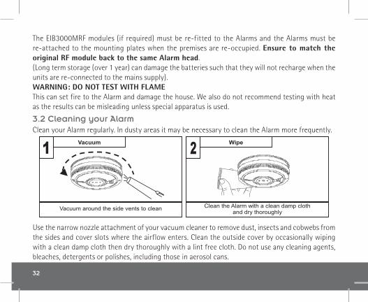
The EIB3000MRF modules (if required) must be re-fitted to the Alarms and the Alarms must be re-attached to the mounting plates when the premises are re-occupied. Ensure to match the original RF module back to the same Alarm head.(Long term storage (over 1 year) can damage the batteries such that they will not recharge when the units are re-connected to the mains supply).WARNING: DO NOT TEST WITH FLAME This can set fire to the Alarm and damage the house. We also do not recommend testing with heat as the results can be misleading unless special apparatus is used.
3.2 Cleaning your AlarmClean your Alarm regularly. In dusty areas it may be necessary to clean the Alarm more frequently.
Use the narrow nozzle attachment of your vacuum cleaner to remove dust, insects and cobwebs from the sides and cover slots where the airflow enters. Clean the outside cover by occasionally wiping with a clean damp cloth then dry thoroughly with a lint free cloth. Do not use any cleaning agents, bleaches, detergents or polishes, including those in aerosol cans.
Vacuum
Vacuum around the side vents to clean
Wipe
Clean the Alarm with a clean damp clothand dry thoroughly

33
WARNING: Do not paint your Alarm.
Other than the cleaning described above, no other customer servicing of this product is required. Servicing or repairs, when needed, must be performed by the manufacturer.
All Alarms are prone to dust and insect ingress, which can cause false alarms or failure to alarm. In certain circumstances, even with regular cleaning, contamination can build up in the smoke sensing chamber causing the Alarm to sound or fail. Contamination is beyond our control, it is totally unpredictable and is considered normal wear and tear. For this reason, contamination is not covered by the guarantee.

34
4What to do in case of alarm

35
(i) Check room doors for heat or smoke. Do not open a hot door. Use an alternate escape route. Close all doors behind you as you leave.
(ii) If smoke is heavy, crawl out, staying close to floor. Take short breaths, if possible, through a wet cloth or hold your breath. More people die from smoke inhalation than from flames.
(iii) Get out as fast as you can. Do not stop for packing. Have a prearranged meeting place outside for all family members. Check everybody is there.
(iv) Call the Fire Brigade immediately on a mobile phone or from a neighbour‘s house. Make sure to call the Brigade for all fires no matter how small - fires can suddenly spread. Also call the Brigade even if the alarm is automatically transmitted to a remote manned centre - the link may have failed.
(v) NEVER re-enter a burning house.NEVER

36
5Troubleshooting
andIndicator summary
tables

37
Your Alarm does not sound when you press the Test button
• Check the Alarm is secured correctly on the mounting plate.• Wait 15 seconds after connecting the power before button testing.• Hold button down firmly for at least 10 seconds.• If the horn does not sound, then your Alarm must be returned for repair
or replacement - see GETTING YOUR ALARM SERVICED section
Your Alarm sounds for no apparent reason
• If, when the Alarm sounds, there is no sign of smoke, heat or noise to indicate that there is a fire, you should get your family into a safe place, before you start investigating.
Check the house carefully in case there is a small fire smouldering somewhere. Check for smoke, fumes, steam, very hot air etc.• Locate the Alarm that sounds and has flashing red LED.• If you have thoroughly investigated and are sure that it is just a nuisance
alarm, simply press the Test/Hush button briefly to silence the Alarm for 10 minutes. This will also silence any interconnected Alarms for the same period. When the Alarm is in ‘Hush’ mode the red LED will continue to flash while it detects the presence of smoke or heat.
The Alarm will reset to normal functionality at the end of the 10 minutes. If additional silenced time is required, simply push the Test/Hush Button again. • If you experience frequent nuisance/false alarms, it may be necessary
to re-locate the Alarm away from the source of the fumes or if it continues to sound without smoke or heat being present and cleaning the Alarm does not solve the problem, it needs to be replaced.

38
Interconnected Alarms do not all sound
• Hold test button down for at least 10 seconds to ensure that the signal is transmitted to all the interconnected Alarms.
• If this is not the case and you have a hardwired interconnection, we recommend you consult a licensed electrician.
• If the Alarm is fitted with an RF module for wireless interconnection, check that all Alarms in the RadioLINK system are powered and are house-coded correctly. (see the EIB3000MRF SmartLINK module manual)
Pressing the Test/Hush button does not silence the Alarm
Always make sure that you are pressing the Test/Hush button on the Alarm that sounds with the red LED flashing.
Your Alarm chirps/beeps/flashes
In standby mode, the Alarm does not sound, beep, chirp or flash. The only light on is the green power LED.
The Alarm automatically monitors the battery, sensor and electronics periodically to ensure that all are satisfactory. If a fault has been found, the Alarm alerts the occupier to this via short chirps from its sounder and its yellow LED fault indicator flashes every 48 seconds. The Alarm will also indicate any faults when the test button is pressed.
See indicator summary table on the next pages

39
Mode
Power up Slide ontomounting plate
Detecting fire
Activatedvia interconnect
Pressing SilenceButton on Alarmdetecting fire
With the test button held the green LED will flicker/pulse every second
= LED on solid = LED flashing
x 10mins
Standby
Testing(monthly)
Press and holdtest button
x 1
Action Green LED(power)
Yellow LED(fault)
Red LED(alarm)
Sound
Normal mode
In alarm mode
x 1 x 1
every48 sec
1
every48 sec
2
every48 sec
Green LED(power)
Yellow LED(fault)
Red LED(alarm)
What to doWhat itmeans
Reconnect ACmains power
Reconnect ACmains power
AC mains off
AC mains offLow battery
backup
Chirps
Fault modes and Memory indicator
ReplaceAlarm
every48 sec
Low batterybackup
ReplaceAlarm
Sensorfault
ReplaceAlarm
End of Life
when pressingTest button
Max DustCompensation
has been reached
1 ON when AC mains power is switched on, flashes every 48s when on backup battery, OFF when both AC mainsand backup battery are off.2 If you are unsure of the amount of flashes of the Yellow LED you can at any time while a fault conditionexists, press the Test button. The relevant number of flashes will then be 8s apart.Note: Fault chirps can be silenced by pressing the Test/Hush button.
see MaximumDust Compensation
section
There hasbeen analarm in
your absence
Check Alarmmemorysection
Flashes asper fault type
Fault chirps have beensilenced. Rate of theyellow LED flashingindicates fault type
If required chirping can besilenced again by pressing
Silence button
Status
every48 secx2
every8 secx2
To erase thememory
Sounds until test buttonis releasedKeep test button pressed for >20s
Press and hold test button
Action Red LED(alarm)
Sound
Memory mode
0-24h
>24h +
What you hear / see
x2
x1
x1
x1
x2
x3
x4
every48 secx3
every8 secx4

40
Mode
Power up Slide ontomounting plate
Detecting fire
Activatedvia interconnect
Pressing SilenceButton on Alarmdetecting fire
With the test button held the green LED will flicker/pulse every second
= LED on solid = LED flashing
x 10mins
Standby
Testing(monthly)
Press and holdtest button
x 1
Action Green LED(power)
Yellow LED(fault)
Red LED(alarm)
Sound
Normal mode
In alarm mode
x 1 x 1
every48 sec
1
every48 sec
2
every48 sec
Green LED(power)
Yellow LED(fault)
Red LED(alarm)
What to doWhat itmeans
Reconnect ACmains power
Reconnect ACmains power
AC mains off
AC mains offLow battery
backup
Chirps
Fault modes and Memory indicator
ReplaceAlarm
every48 sec
Low batterybackup
ReplaceAlarm
Sensorfault
ReplaceAlarm
End of Life
when pressingTest button
Max DustCompensation
has been reached
1 ON when AC mains power is switched on, flashes every 48s when on backup battery, OFF when both AC mainsand backup battery are off.2 If you are unsure of the amount of flashes of the Yellow LED you can at any time while a fault conditionexists, press the Test button. The relevant number of flashes will then be 8s apart.Note: Fault chirps can be silenced by pressing the Test/Hush button.
see MaximumDust Compensation
section
There hasbeen analarm in
your absence
Check Alarmmemorysection
Flashes asper fault type
Fault chirps have beensilenced. Rate of theyellow LED flashingindicates fault type
If required chirping can besilenced again by pressing
Silence button
Status
every48 secx2
every8 secx2
To erase thememory
Sounds until test buttonis releasedKeep test button pressed for >20s
Press and hold test button
Action Red LED(alarm)
Sound
Memory mode
0-24h
>24h +
What you hear / see
x2
x1
x1
x1
x2
x3
x4
every48 secx3
every8 secx4
The Alarm memory is an important feature where even if the house is unoccupied during an alarm condition it warns the homeowner that the Alarm has previously detected Fire and been in alarm. The memory feature also helps identify the unit which has previously triggered an entire alarm system, which can also be very helpful after the entire alarm system has gone into alarm and then stopped, for no obvious reason. Once the source alarm has been identified, appropriate action can be taken e.g. in the case of a fire alarm event in memory, investigate the cause of nuisance / false alarms by ensuring kitchen or bathroom doors are kept closed to prevent very hot air or steam from cookers / showers reaching the heat sensor on the Alarm, locate the Alarm further away from the source of steam or condensation, replace the Alarm if it is thought to be defective or remove the unit in the short term. The memory feature has two operation modes: - memory indication for 24 hour period after alarm. - memory recall on demand 24-hour memory indicators: For 24 hours after alarming, the red LED will flash twice every 48 seconds (approx) Memory recall on demand: To review the memory status at any time, press and hold the test button, the red LED will flash twice to convey the alarm event in memory, if any. Reset Memory: Hold down the test button for at least 20 seconds. Cover the horn with a cloth to muffle the alarm during this time. Clearing of the memory is indicated by a 1-second-long flash of the red LED. Please note that the alarm memory will also be reset if the Alarm is removed from its mounting plate.

41
Mode
Power up Slide ontomounting plate
Detecting fire
Activatedvia interconnect
Pressing SilenceButton on Alarmdetecting fire
With the test button held the green LED will flicker/pulse every second
= LED on solid = LED flashing
x 10mins
Standby
Testing(monthly)
Press and holdtest button
x 1
Action Green LED(power)
Yellow LED(fault)
Red LED(alarm)
Sound
Normal mode
In alarm mode
x 1 x 1
every48 sec
1
every48 sec
2
every48 sec
Green LED(power)
Yellow LED(fault)
Red LED(alarm)
What to doWhat itmeans
Reconnect ACmains power
Reconnect ACmains power
AC mains off
AC mains offLow battery
backup
Chirps
Fault modes and Memory indicator
ReplaceAlarm
every48 sec
Low batterybackup
ReplaceAlarm
Sensorfault
ReplaceAlarm
End of Life
when pressingTest button
Max DustCompensation
has been reached
1 ON when AC mains power is switched on, flashes every 48s when on backup battery, OFF when both AC mainsand backup battery are off.2 If you are unsure of the amount of flashes of the Yellow LED you can at any time while a fault conditionexists, press the Test button. The relevant number of flashes will then be 8s apart.Note: Fault chirps can be silenced by pressing the Test/Hush button.
see MaximumDust Compensation
section
There hasbeen analarm in
your absence
Check Alarmmemorysection
Flashes asper fault type
Fault chirps have beensilenced. Rate of theyellow LED flashingindicates fault type
If required chirping can besilenced again by pressing
Silence button
Status
every48 secx2
every8 secx2
To erase thememory
Sounds until test buttonis releasedKeep test button pressed for >20s
Press and hold test button
Action Red LED(alarm)
Sound
Memory mode
0-24h
>24h +
What you hear / see
x2
x1
x1
x1
x2
x3
x4
every48 secx3
every8 secx4
42
The Alarm can communicate its status and history through various Led flashes and chirps/beeps. However, a more comprehensive report of all such events is available through the AudioLINK download via the App.
Low Battery Backup Fault
If the battery backup supply is depleted, the sounder will give one short chirp with one yellow LED fault indicator flash every 48 seconds. In this case check that the green LED power indicator is on continuously. If it is off, or flashing every 48 seconds, the Alarm is not receiving 230V AC mains power and is being powered by the battery backup. The chirp every 48 seconds indicates that the battery is depleted. The battery is not replaceable. Check fuses, circuit breakers and wiring to determine the cause of the interruption to the mains power. If in doubt, contact a qualified electrician. Once mains power is reinstated, the chirps should cease within 2 hours as the battery charges up. If the chirping persists for over 2 hours with the green light on, there may be some other problem with the Alarm. The Alarm must be returned for repair or replacement - see GETTING YOUR ALARM SERVICED section.
Sensor Fault
The Alarm regularly checks the photoelectric smoke sensor and/or thermistor heat sensor for correct operation. If the Alarm has found a fault with the sensor, it will give 2 short chirps with 2 yellow LED flashes every 48 seconds. In this case, the Alarm must be returned for repair or replacement - see GETTING YOUR ALARM SERVICED section
End of Life
Once the Alarm passes its 10th year of installation, it will give 3 short chirps with 3 yellow LED flashes every 48 seconds to indicate it has reached its end of useful life.

43
The entire Alarm must be replaced (Also check the replace by date on the label on the side of the Alarm). Disconnect the mains first and replace the Alarm - see ‚Removing the Alarm‘ section.
Maximum Dust Compensation (EIB3016 and EIB3024 only)
The Alarm monitors the dust contamination build-up in the optical smoke chamber and then compensates for it, reducing the possibility of false alarms.If however, the Alarm gives 4 short chirps with 4 yellow LED flashes when the test button is pressed, it indicates that the Alarm has reached the maximum dust compensation. When this occurs, the Alarm will continue to operate as normal, but there is an increased risk of false alarms caused by dust contamination. If contamination has occurred quickly (e.g. due to dust from carpets being replaced) and the Alarms are sounding, the dust compensation may take some hours to operate. In this situation, remove the Alarm from the ceiling, leave it disconnected for 5 minutes, then reinstall the unit (the air must be clean i.e., dust and smoke free). The dust compensation will now operate quickly, within 60 seconds.
Temporarily Silencing the Fault chirps
If the test / hush button is pressed on an Alarm that is giving fault chirps and yellow LED fault indicator flashes, the Alarm will be silenced (Fault Hush mode) for a period of 12 hours. However, the Alarm will sound / function as normal within that period should it detect Fire (except if the fault detected is a sensor fault). The yellow LED fault indicator will continue to flash as before to indicate the fault is still present. This is a useful feature should the fault occur at night as it keeps the disturbance at a time when people in the building are trying to sleep to a minimum. The fault chirps would return 12 hours later, which perhaps may be a more suitable time to address the fault issue with the Alarm. In case of low backup battery voltage and end of life fault chirps, this can be repeated as required. A sensor fault condition can only be hushed once.

44
6Important
safeguards
45
Limitations of Alarms
Multi-Sensor / Smoke / Heat Alarms can significantly help to reduce the risk of fire fatalities. However independent authorities have stated that these systems may be ineffective in some fire situations. There are a number of reasons for this:- The Alarms will not work if the mains power supply is off or disconnected and the backup battery
is depleted. Test regularly to ensure the power supply is functioning as required.- The Alarms will not detect fire if sufficient heat/smoke does not reach the Alarms. Heat/smoke
may be prevented from reaching the Alarm if the fire is too far away, for example, if the fire is on another floor, behind a closed door, in a chimney, in a wall cavity, or if the prevailing air drafts carry the heat/smoke away. Installing Alarms on both sides of closed doors and throughout the house or premises as recommended in this leaflet will very significantly improve the probability of early detection.
- The Alarms may not be heard. An Alarm may not wake a person who has taken drugs or alcohol. - The Alarms may not detect every type of fire to give sufficient early warning.- The Alarms don’t last indefinitely. The manufacturer recommends regular monthly testing and
replacement after, at most, 10 years, as a precaution.
46
When an alarm system is installed, basic safety precautions should always be followed, including those listed below:
• Please read all instructions.
• Use the Testing of the Alarm as a means to familiarise your family with the alarm sound and to practice fire drills regularly with all family members. Rehearse emergency escape plans so everyone at home knows what to do in case the Alarm sounds. Further information can be obtained from your local fire prevention officer.
• To maintain sensitivity to Fire, do not paint or cover the Alarm in any manner and; do not allow cobwebs, dust or grease to accumulate.
• If the Alarm has been damaged in any way or does not function properly, do not attempt a repair. Return the Alarm - see Section 7 - ‘SERVICE AND GUARANTEE‘ section.
• This appliance is only intended for premises having a residential type environment.
• Alarms are not a substitute for insurance. The supplier or manufacturer is not your insurer. • Do not dispose of your Alarm in a fire.

47
7Service and Guarantee

48
7.1 Getting your Alarm serviced
If, within the guarantee period, your Alarm fails to work after you have carefully read all the instructions, checked the unit has been installed correctly, and is receiving AC power, then contact us.
If you are advised to return your Alarm, please ensure that the Alarm is placed in a padded box, not attached to the mounting plate (as the Alarm can give beeps or alarm if the Test/Hush button is pressed during shipping), with the proof of purchase and a note stating the nature of the fault.
7.2 GuaranteeBrooks guarantees this Alarm for five years from the date of purchase against any defects that are due to faulty materials or workmanship. If this Alarm should become defective within the guarantee period, we shall at our discretion repair or replace the faulty unit.
This guarantee only applies to normal conditions of use and service, and does not include damage resulting from accident, neglect, misuse, unauthorised dismantling, or contamination howsoever caused. This guarantee excludes incidental and consequential damage.
This guarantee does not apply to any product that has been modified in any way by a third party or has been fitted with a third party element.
Do not interfere with the Alarm or attempt to tamper with it. This will invalidate the guarantee but more importantly may expose the user to shock or fire hazards.
This guarantee is in addition to your statutory rights as a consumer.

49
Photoelectric Alarm EIB3016 conforms to AS3786:2014Heat Alarm EIB3014 conforms to AS1603.3:2018
Multi Alarm EIB3024 conforms to AS3786:2014 & AS1603.3:2018

50 © Brooks 2019
P/N B19343 Rev1
Brooks Australia PTY Ltd.NSW - Head Office
P.O. Box 7050 Silverwater NSW 18114 Pike Street Rydalmere NSW 2116
Ph: 02 9684 1466 Website: www.Brooks.com.au
VIC1/3 Molan Street, Ringwood, VIC 3134
Ph: 03 9879 5294
SAP.O. Box 101 Woodville SA 5011
729A Port Road, Woodville, SA 5011Ph: 08 8347 0000
QLDP.O. Box 511 Archerfield QLD 4108
2/49 Boyland Ave Coopers Plains, QLD 4108Ph: 07 3373 8222
WAP.O. Box 2114, Midland DC W.A. 6936
6/91 Leach Highway, Kewdale WA 6105Ph: 08 6262 8095
New ZealandUnit 106 “The Zone” 23 Edwin St, Mt Eden, Auckland 1024Ph: +64 9 638 4644 - Toll Free 0800 220 007 (NZ only)
or National Australian Sales Number: 1300 78 FIRE (3473)For the cost of local call