Embed Size (px)
Citation preview
Maine Erosion and Sediment Control Practices Field Guide
for Contractors
Maine Department of Environmental Protection

ACKNOWLEDGEMENTSProduction2014 Revision: Marianne Hubert, Senior Environmental Engineer, Division of Watershed Management, Bureau of Land and Water Quality, Department of Environmental Protection (DEP).
Illustrations: Photos obtained from SJR Engineering Inc., Shaw Brothers Construction Inc., Bar Mills Ecological, Maine Department of Transportation (MaineDOT), Maine Land Use Planning Commission (LUPC) and Maine Department of Environmental Protection (DEP).
TECHNICAL REVIEW COMMITTEE: The following people participated in the revision of this manual:
Steve Roberge, SJR Engineering, Inc., Augusta
Ross Cudlitz, Engineering Assistance & Design, Inc., Yarmouth
Susan Shaller, Bar Mills Ecological, Buxton
David Roque, Department of Agriculture, Conservation & Forestry
Peter Newkirk, MaineDOT
Bob Berry, Main-Land Development Consultants
Daniel Shaw, Shaw Brothers Construction
Peter Hanrahan, E.J. Prescott
William Noble, William Laflamme, David Waddell, Kenneth Libbey, Ben Viola, Jared Woolston, and Marianne Hubert of the Maine DEP
Revision (2003): The manual was revised and reorganized with illustrations (original manual, Salix, Applied Earthcare and Ross Cudlitz, Engineering Assistance & Design, Inc.).
Original Manual (1991): The original document was funded from a US Environmental Protection Agency Federal Clean Water Act grant to the Maine Department of Environmental Protection, Non-Point Source Pollution Program and developed under contract by the Cumberland County Soil and Water Conservation District.
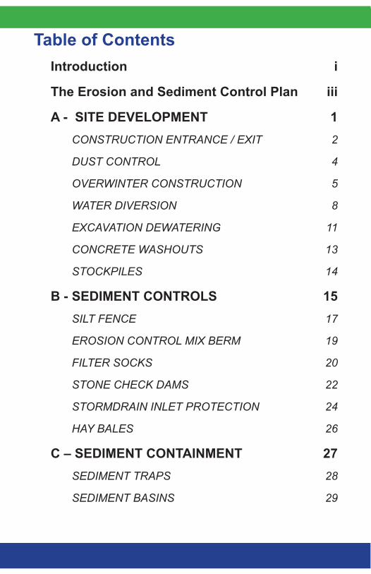
Table of ContentsIntroduction i
The Erosion and Sediment Control Plan iii
A - SITE DEVELOPMENT 1CONSTRUCTION ENTRANCE / EXIT 2
DUST CONTROL 4
OVERWINTER CONSTRUCTION 5
WATER DIVERSION 8
EXCAVATION DEWATERING 11
CONCRETE WASHOUTS 13
STOCKPILES 14
B - SEDIMENT CONTROLS 15SILT FENCE 17
EROSION CONTROL MIX BERM 19
FILTER SOCKS 20
STONE CHECK DAMS 22
STORMDRAIN INLET PROTECTION 24
HAY BALES 26
C – SEDIMENT CONTAINMENT 27SEDIMENT TRAPS 28
SEDIMENT BASINS 29
GEOTEXTILE FILTER BAG 32
FLOCCULANTS (POLYMERS) 34
D - MULCHING 35HAY/STRAW MULCH 37
EROSION CONTROL BLANKETS 39
EROSION CONTROL MIX 41
HYDRAULIC MULCH 43
E - VEGETATION 44TOPSOIL 46
SEEDBED PREPARATION 47
VEGETATION APPLICATION 48
SODDING 50
HYDROSEEDING 50
F - SLOPES 51CUTS AND FILLS 53
GEOTEXTILES 55
RIPRAP 56
GABIONS 61
TURF-REINFORCED MATTING (TRM) 63
CELLULAR CONFINEMENT SYSTEMS 64
SLOPE DRAINS 65
G - SWALES AND DITCHES 67VEGETATED CHANNELS 69
RIPRAP CHANNEL 72
TURF REINFORCEMENT MAT 74
LEVEL SPREADERS 75
H - CROSS-CULVERTS 78PIPE INLET PROTECTION 81
OUTLET PROTECTION 82
I - ROADS 85GRAVEL ROADS 86
DITCH TURNOUTS 89
FRENCH DRAINS AND ROCK SANDWICHES 92
J - STREAM CROSSINGS 94CULVERT CROSSINGS 95
TEMPORARY STREAM DIVERSION 99
IN-WATER WORK 101
TEMPORARY STREAM CROSSINGS 103
APPENDIX A: Erosion and Sediment Control Laws in Maine 106
APPENDIX B: MaineDOT Standard Specifications 109
i
Contaminants, sediments or nutrients such as phosphorus, attach to the soil particles and contribute to “non-point source pollution”. The environmental impact of erosion and sedimentation can be irreparable; and planning for and preventing the erosion in the first place can be less costly than labor intensive repairs later. The purpose of this handbook is to help land developers, consultants, and contractors use the appropriate erosion and sedimentation control Best Management Practices (BMPs) for the site and conditions whenever disturbing soil or removing a natural ground cover.
Large-scale development areas exposed to erosion during construction have the greatest potential for significant sedimentation of a resource. But, a small discharge of turbid water from a simple residential lot development can also have damaging effects.
WHAT ARE EROSION AND SEDIMENTATION?Soil erosion is the detachment of soil particles and loss of surficial soil by the actions of water, ice, gravity, or wind. Water-generated erosion causes the most severe damage to a site under development. Sedimentation is the consequence of erosion when the eroded soil particles are deposited in a new location.
HOW DOES EROSION OCCUR?
Because the rate of erosion compounds exponentially, it is vital to control its initial stages.
• Raindroperosion occurs when raindrops falls and dislodges individual soil particles from an unprotected soil surface. These particles are easily picked up and transported great distances by stormwater runoff.
Introduction
ii
• Sheeterosion occurs when the runoff removes a whole layer of an unprotected soil surface.
• Rillandgullyerosion occurs as the runoff concentrates in rivulets and cuts into the soil surface. When not repaired, the rills develop into larger gullies.
• Streamandchannelerosion occurs as the increased volume and velocity of the runoff reaches a stream or waterway and cuts away at the banks of the channel.
OTHER FACTORS LINKED TO EROSIONErosion potential is directly related to the soil’s capacity to hold and transfer water such as:
• Soils with good structure are less prone to erosion; but soil compaction like soil disturbance may destroy the soil structure, and increase erosion and runoff potential. A soil with high amounts of silt or very fine sand is more erodible than a soil with a higher percentage of clay or organic matter. Well-drained and well-graded gravels with little or no silt are the least erodible soils.
• A ground surface that is well vegetated is shielded from the impact of falling rain and will resist the velocity of runoff. Also, the root systems hold the soil particles and aid in absorbing water. Pavement or a gravel base is also considered a proper cover.
• A slope length and gradient will determine the velocity of the runoff and the extent of erosion. Steep and/or long slopes are the most subject to erosion.
• The intensity and duration of a rainfall event determines the volume and velocity of runoff and therefore its energy. Long duration rainfall events cause the most severe erosion.
iii
All projects permitted through the DEP need an erosion and sediment control (ESC) plan; but proper planning is also important for all other projects, and especially if located in an area at risk of eroding and causing sedimentation. The ESC plan should be prepared during the design phase and before construction begins; and the contractor should understand the plan, implement it in a timely manner, and adjust the measures as site or weather conditions change. The ESC plan only establishes the minimum required measures. The plan consists of three parts:
1. A description:
• Existing conditions and the proposed activities, site conditions (soils, topography, vegetation, property lines, buildings, etc.), and adjacent protected natural resources (streams, wetlands, slopes, bare or highly erodible soils, significant wildlife habitats, etc.).
• Areas that are subject to serious erosion problems.• Measures that will be used to control erosion and
sedimentation, where they will be installed and when needed.
• Construction schedule and planned inspections with frequency and required maintenance.
2. Site Plans
• Topographic land contours and drainage before and after construction.
• The limits of vegetation clearing and grading.• Any vegetated buffers that should be protected.• Sensitive areas within 100 feet of the site (streams,
lakes, wetlands or areas sensitive to erosion.
The Erosion and Sediment Control Plan

iv
• Drainage swales, ditches, roads, and stormwater control structures.
• The location and types of ESC measures.
3. Construction Details
• Plans and standards of ESC structures.• Amount, type and installation details for seeding,
mulching and other vegetative specifications.• All pertinent maintenance instructions.• Schedule for stabilization and revegetation including
overwinter stabilization measures if the work extends into the winter construction period (see Overwinter Construction).
IMPORTANT NOTE:
Consider and plan for unforeseen conditions, weather and delays that may affect the construction schedule and BMP performance. Will grading be completed before winter? Will all measures be effective during each phase of the project?
v
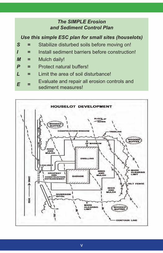
The SIMPLE Erosion and Sediment Control Plan
Use this simple ESC plan for small sites (houselots)S = Stabilize disturbed soils before moving on!I = Install sediment barriers before construction!M = Mulch daily!P = Protect natural buffers!L = Limit the area of soil disturbance!
E = Evaluate and repair all erosion controls and sediment measures!
vi
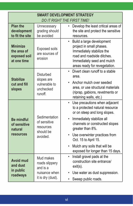
SMART DEVELOPMENT STRATEGYDO IT RIGHT THE FIRST TIME!
Plan the development to fit the site
Unnecessary grading should be avoided
• Develop the least critical areas of the site and protect the sensitive resources.
Minimize the area of exposed soil at one time
Exposed soils are sources of erosion
• Build a large development project in small phases. Immediately stabilize the road and roadside ditches. Immediately seed and mulch areas ready for revegetation.
Stabilize cut and fill slopes
Disturbed slopes are vulnerable to unchecked runoff.
• Divert clean runoff to a stable area.
• Anchor mulch over seeded area, or use structural materials (riprap, gabions, revetments or retaining walls, etc.)
Be mindful of sensitive natural resources
Sedimentation of sensitive resources should be avoided.
• Use precautions when adjacent to a protected natural resource or on steep and long slopes.
• Immediately stabilize all channels or constructed slopes greater than 8%.
• Use overwinter practices from Oct. 15 to April 15.
• Mulch any soils that will be exposed for longer than 15 days.
Avoid mud and dust in public roadways
Mud makes roads slippery and is a nuisance when it is dry (dust).
• Install gravel pads at the construction site entrance/exit(s).
• Use water as dust suppression.• Sweep public roads.
vii
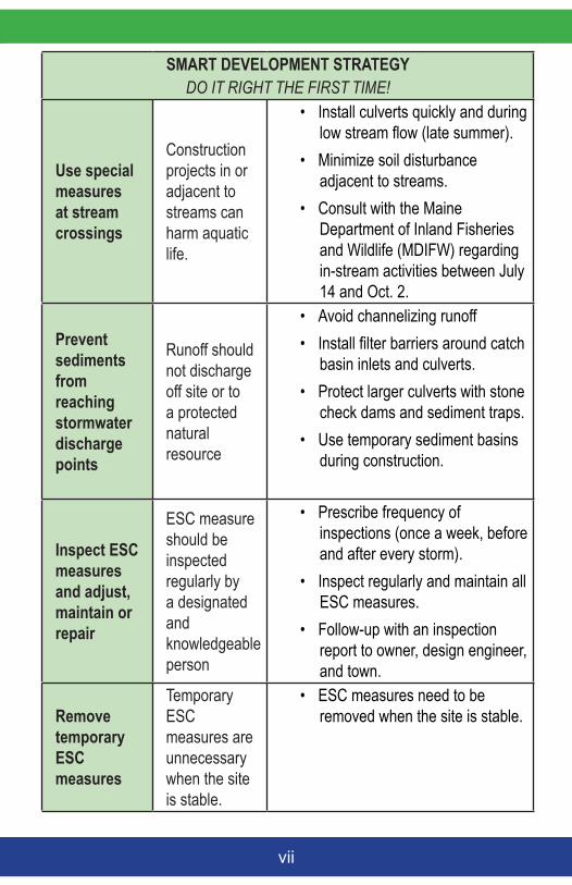
SMART DEVELOPMENT STRATEGYDO IT RIGHT THE FIRST TIME!
Use special measures at stream crossings
Construction projects in or adjacent to streams can harm aquatic life.
• Install culverts quickly and during low stream flow (late summer).
• Minimize soil disturbance adjacent to streams.
• Consult with the Maine Department of Inland Fisheries and Wildlife (MDIFW) regarding in-stream activities between July 14 and Oct. 2.
Prevent sediments from reaching stormwater discharge points
Runoff should not discharge off site or to a protected natural resource
• Avoid channelizing runoff • Install filter barriers around catch
basin inlets and culverts.• Protect larger culverts with stone
check dams and sediment traps.• Use temporary sediment basins
during construction.
Inspect ESC measures and adjust, maintain or repair
ESC measure should be inspected regularly by a designated and knowledgeable person
• Prescribe frequency of inspections (once a week, before and after every storm).
• Inspect regularly and maintain all ESC measures.
• Follow-up with an inspection report to owner, design engineer, and town.
Remove temporary ESC measures
Temporary ESC measures are unnecessary when the site is stable.
• ESC measures need to be removed when the site is stable.
Site
D
evel
opm
ent
1
A - SITE DEVELOPMENTConsiderations of the existing site conditions, and phasing the construction and development will reduce site vulnerability to uncontrolled erosion and sedimentation. It will save both time and money!
IMPORTANT NOTES:
Beware of site development hidden costs! Phasing and installing effective passive erosion control measures will be less costly and simpler to manage than having to provide structural sedimentation measures in concentrated flows or for large volume of water.
Appropriate ESC protection is necessary for steep slopes, erodible soils or where surface water or groundwater makes permanent stabilization difficult. Sites in loamy soils are more erodible than sandy or clayey soils.
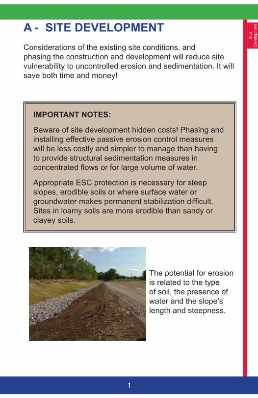
The potential for erosion is related to the type of soil, the presence of water and the slope’s length and steepness.
Site
Developm
ent
2
A pad of coarse aggregate at the construction entrance/exit will reduce the tracking of soil from construction traffic onto a public street. Sediments from the tire treads are knocked loose by the angular stones and are trapped in the voids between the stones.
COMPANION BMPs: Sediment Trapping and Sediment Barriers
CONSTRUCTION SPECIFICATIONS
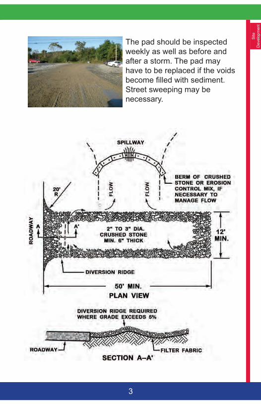
• The entrance/exit pad should have a length of 50 feet or more and a 12-foot minimum width (or as appropriate to contain the wheel base of construction vehicles plus 3 feet on either side).
• The pad should be 6 inches or more thick with angular aggregate (2-3 inch diameter). Appropriate reclaimed concrete material may be used.
• The aggregate should be placed over a geotextile filter to prevent the stones from pushing into the native soil.
• At the bottom of slopes, a diversion ridge should be provided to intercept runoff.
• Berms may be necessary to divert water around any exposed soil, and runoff should be directed to a sediment trap.
• The wheels of construction equipment may be washed prior to exiting the site. Washing should be performed in an area that drains to a sediment trap or basin.
CONSTRUCTION ENTRANCE / EXIT
Site
D
evel
opm
ent
3
The pad should be inspected weekly as well as before and after a storm. The pad may have to be replaced if the voids become filled with sediment. Street sweeping may be necessary.
Site
Developm
ent
4
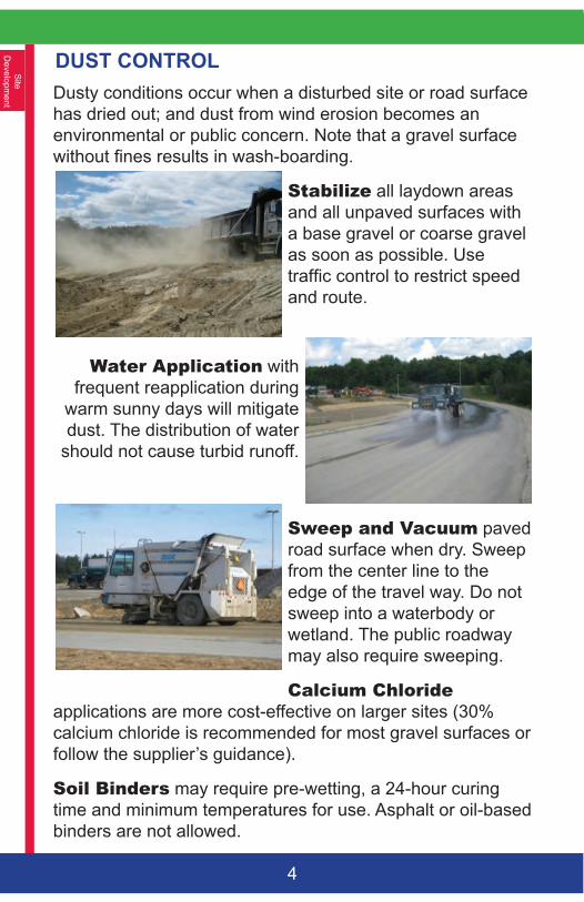
DUST CONTROLDusty conditions occur when a disturbed site or road surface has dried out; and dust from wind erosion becomes an environmental or public concern. Note that a gravel surface without fines results in wash-boarding.
Stabilize all laydown areas and all unpaved surfaces with a base gravel or coarse gravel as soon as possible. Use traffic control to restrict speed and route.
WaterApplication with frequent reapplication during
warm sunny days will mitigate dust. The distribution of water
should not cause turbid runoff.
SweepandVacuum paved road surface when dry. Sweep from the center line to the edge of the travel way. Do not sweep into a waterbody or wetland. The public roadway may also require sweeping.
CalciumChloride applications are more cost-effective on larger sites (30% calcium chloride is recommended for most gravel surfaces or follow the supplier’s guidance).
SoilBinders may require pre-wetting, a 24-hour curing time and minimum temperatures for use. Asphalt or oil-based binders are not allowed.
Site
D
evel
opm
ent
5
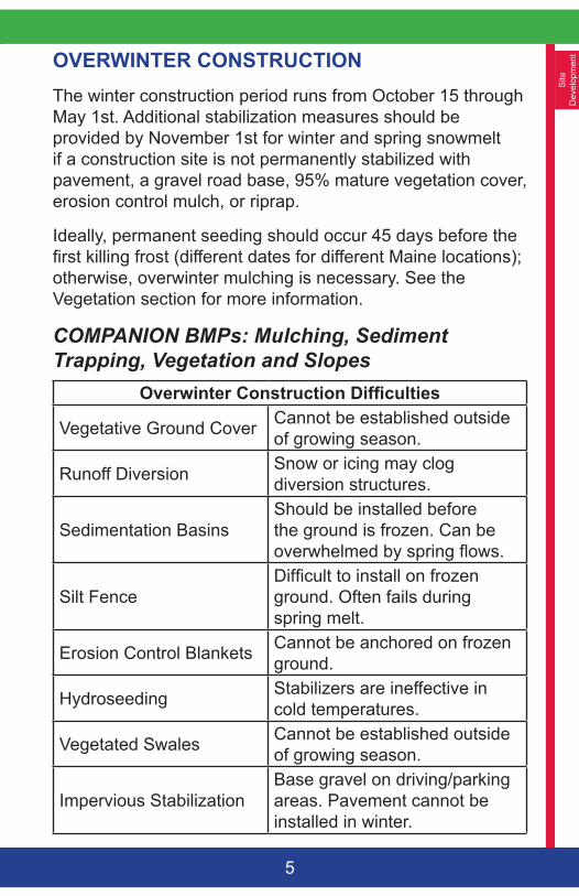
OVERWINTER CONSTRUCTIONThe winter construction period runs from October 15 through May 1st. Additional stabilization measures should be provided by November 1st for winter and spring snowmelt if a construction site is not permanently stabilized with pavement, a gravel road base, 95% mature vegetation cover, erosion control mulch, or riprap.
Ideally, permanent seeding should occur 45 days before the first killing frost (different dates for different Maine locations); otherwise, overwinter mulching is necessary. See the Vegetation section for more information.
COMPANION BMPs: Mulching, Sediment Trapping, Vegetation and Slopes
Overwinter Construction Difficulties
Vegetative Ground Cover Cannot be established outside of growing season.
Runoff Diversion Snow or icing may clog diversion structures.
Sedimentation BasinsShould be installed before the ground is frozen. Can be overwhelmed by spring flows.
Silt FenceDifficult to install on frozen ground. Often fails during spring melt.
Erosion Control Blankets Cannot be anchored on frozen ground.
Hydroseeding Stabilizers are ineffective in cold temperatures.
Vegetated Swales Cannot be established outside of growing season.
Impervious StabilizationBase gravel on driving/parking areas. Pavement cannot be installed in winter.
Site
Developm
ent
6
OverwinterHayMulch should be applied at double the normal rate (150 pounds per 1000 square feet or 3 tons/acre) and should be anchored with netting (peg and twine) or a tackifier to prevent mulch displacement before freezing conditions. No soil should be visible through the mulch. Hay mulch cannot be applied over snow.
DormantSeedingandMulch should be applied at 3 times the specified amount after the first killing frost. All dormant seeding beds should be covered with overwinter hay mulch or an anchored erosion control blanket.
Temporaryvegetation should be applied by October 1st with winter rye at 3 pounds per 1000 square feet, and mulched with anchored hay at 75 pounds per 1000 square feet or with erosion control blankets. If the rye fails to grow at least three inches and have 75% coverage by November 1st, the area should be stabilized for overwinter protection.
Erosioncontrolmix is the best overwinter cover, but is not recommended for slopes steeper than 1:1 or in areas with flowing water.
ErosionControlBlankets should be used on slopes where hay would be disturbed by wind or water. The matting should be installed, anchored and stapled in accordance with the manufacturer’s recommendations. Full contact between the blanket and the soil is critical for an effective erosion control cover.
Riprapshould be properly sized and installed to ensure long-term stability. In the winter, newly constructed ditches and channels should be stabilized with riprap. Widening of the channel may be required to accommodate the placement of stones. Angular riprap is preferred to round stone (tailings).
Site
D
evel
opm
ent
7
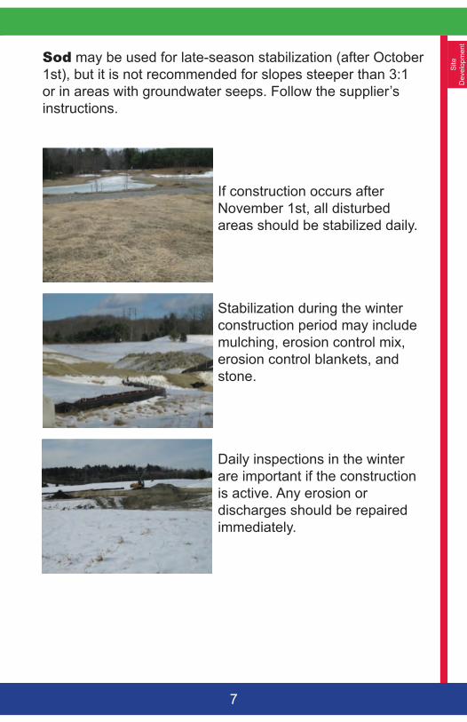
Sod may be used for late-season stabilization (after October 1st), but it is not recommended for slopes steeper than 3:1 or in areas with groundwater seeps. Follow the supplier’s instructions.
If construction occurs after November 1st, all disturbed areas should be stabilized daily.
Stabilization during the winter construction period may include mulching, erosion control mix, erosion control blankets, and stone.
Daily inspections in the winter are important if the construction is active. Any erosion or discharges should be repaired immediately.
Site
Developm
ent
8
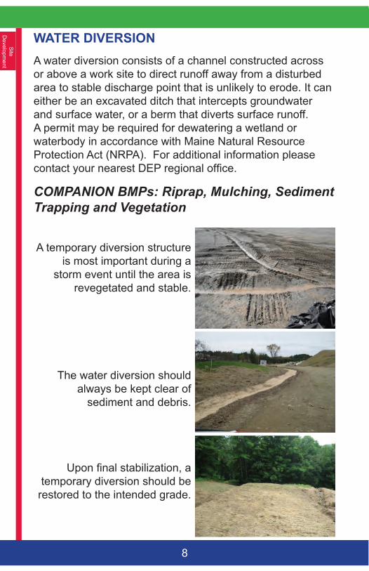
WATER DIVERSION A water diversion consists of a channel constructed across or above a work site to direct runoff away from a disturbed area to stable discharge point that is unlikely to erode. It can either be an excavated ditch that intercepts groundwater and surface water, or a berm that diverts surface runoff. A permit may be required for dewatering a wetland or waterbody in accordance with Maine Natural Resource Protection Act (NRPA). For additional information please contact your nearest DEP regional office.
COMPANION BMPs: Riprap, Mulching, Sediment Trapping and Vegetation
A temporary diversion structure is most important during a
storm event until the area is revegetated and stable.
The water diversion should always be kept clear of
sediment and debris.
Upon final stabilization, a temporary diversion should be
restored to the intended grade.
Site
D
evel
opm
ent
9
CONSTRUCTION SPECIFICATIONS• The condition of the site topography, land use,
soil type and length of slope should determine the location of a diversion.
• The diversion should be angled away from the slope (with a 2-3% downward gradient) for positive drainage to a stable discharge point (plunge pool, level spreader or energy dissipater).
• Diversions designed to protect buildings and roads should have the capacity to manage the runoff from a large storm event.
• Diversions should not be used below high sediment-producing areas unless maintained and monitored daily.
• Exposed soils should be shaped, graded, and stabilized immediately unless a diversion will be provided to direct any runoff to a temporary sedimentation structure.
• All diversion dikes and berms should be compacted and stabilized with material that is appropriate for the slope and expected runoff (erosion control blankets, gravel or riprap).
• A diversion berm should be wide and the dike deep enough to allow for maintenance access as well as contain the volume of runoff.
• Any gullies or depressions crossed by the diversion should be filled, compacted, and stabilized.
• On long slopes, multiple diversions will manage smaller volumes of runoff and be less likely to fail.
Site
Developm
ent
10
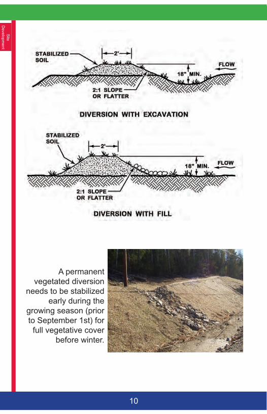
A permanent vegetated diversion
needs to be stabilized early during the
growing season (prior to September 1st) for full vegetative cover
before winter.
Site
D
evel
opm
ent
11
EXCAVATION DEWATERINGDewatering occurs in 3 phases: removing the water from the excavation area (gravity drain, mechanical pumping, siphoning or using the bucket of construction equipment); providing settlement from the collected water (sediment basin or trap, bag, etc.); and providing a stable discharge point.
COMPANION BMPs: Sediment Trapping, Vegetation, and Slopes
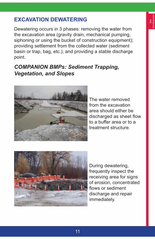
The water removed from the excavation area should either be discharged as sheet flow to a buffer area or to a treatment structure.
During dewatering, frequently inspect the receiving area for signs of erosion, concentrated flows or sediment discharge and repair immediately.
Site
Developm
ent
12
CONSTRUCTION SPECIFICATIONS• The discharge to the sediment treatment area
should never exceed its capacity. • Divert upgradient clean runoff away from an
excavated area.• Avoid discharging to an unstable area, newly
vegetated or within 100 feet of a natural resource. • A positive displacement pump is recommended
when pumping is necessary and the water contains a lot of sediment.
• The elevation of the pump above the water intake and the distance of the discharge hose will greatly affect its pumping capacity.
• Any channel dug for discharging water should be stabilized with ditch lining (riprap, geotextile fabric, plastic sheeting, etc.).
• Limit the length of a trench excavation to 500 feet at any one time (the excavated material should be placed upgradient of the trench).
• If the collected runoff is contaminated with oil, grease, or other petroleum products, filtering through an oil/water separator or a filtration mechanism is recommended. The DEP should be contacted for any significant known spill or unknown source of contaminant.
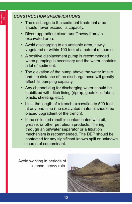
Avoid working in periods of intense, heavy rain.
Site
D
evel
opm
ent
13
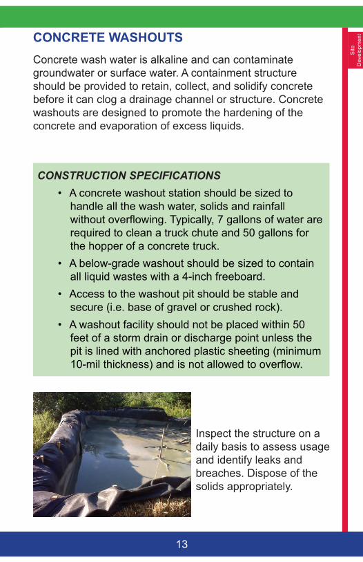
CONCRETE WASHOUTSConcrete wash water is alkaline and can contaminate groundwater or surface water. A containment structure should be provided to retain, collect, and solidify concrete before it can clog a drainage channel or structure. Concrete washouts are designed to promote the hardening of the concrete and evaporation of excess liquids.
CONSTRUCTION SPECIFICATIONS• A concrete washout station should be sized to
handle all the wash water, solids and rainfall without overflowing. Typically, 7 gallons of water are required to clean a truck chute and 50 gallons for the hopper of a concrete truck.
• A below-grade washout should be sized to contain all liquid wastes with a 4-inch freeboard.
• Access to the washout pit should be stable and secure (i.e. base of gravel or crushed rock).
• A washout facility should not be placed within 50 feet of a storm drain or discharge point unless the pit is lined with anchored plastic sheeting (minimum 10-mil thickness) and is not allowed to overflow.
Inspect the structure on a daily basis to assess usage and identify leaks and breaches. Dispose of the solids appropriately.
Site
Developm
ent
14
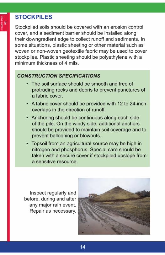
STOCKPILES Stockpiled soils should be covered with an erosion control cover, and a sediment barrier should be installed along their downgradient edge to collect runoff and sediments. In some situations, plastic sheeting or other material such as woven or non-woven geotextile fabric may be used to cover stockpiles. Plastic sheeting should be polyethylene with a minimum thickness of 4 mils.
CONSTRUCTION SPECIFICATIONS• The soil surface should be smooth and free of
protruding rocks and debris to prevent punctures of a fabric cover.
• A fabric cover should be provided with 12 to 24-inch overlaps in the direction of runoff.
• Anchoring should be continuous along each side of the pile. On the windy side, additional anchors should be provided to maintain soil coverage and to prevent ballooning or blowouts.
• Topsoil from an agricultural source may be high in nitrogen and phosphorus. Special care should be taken with a secure cover if stockpiled upslope from a sensitive resource.
Inspect regularly and before, during and after
any major rain event. Repair as necessary.
Sed
imen
t C
ontro
ls
15
B - SEDIMENT CONTROLSSediment barriers should be installed downgradient of all disturbed soils. There are many available types of sediment barriers provided they are installed, used, and maintained properly.
IMPORTANT NOTE:
Sediment barriers reduce runoff velocity and allow for soil settlement. If water has a chance to concentrate and gain velocity, most sediment control barriers will fail. Water velocity is a critical element of erosion.
COMPANION BMPs: Mulching, Vegetation, Riprap, Slopes and Roads
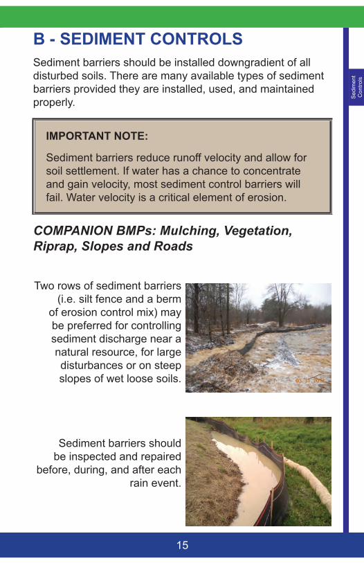
Two rows of sediment barriers (i.e. silt fence and a berm
of erosion control mix) may be preferred for controlling sediment discharge near a natural resource, for large disturbances or on steep slopes of wet loose soils.
Sediment barriers should be inspected and repaired
before, during, and after each rain event.
Sedim
ent C
ontrols
16
CONSTRUCTION SPECIFICATIONS• Sediment barriers should be installed prior to soil
disturbance.• All barriers should be installed on the land contour
and each end curved uphill to prevent bypass (to an elevation higher than the top of the barrier).
• The runoff from the contributing area should not exceed the capacity of the barrier; or mid-slope barriers may be necessary. The drainage flow length should be no longer than 100 feet.
• Where possible, a level area immediately up-gradient of the barrier should be provided for ponding and absorption.
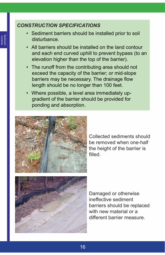
Collected sediments should be removed when one-half the height of the barrier is filled.
Damaged or otherwise ineffective sediment barriers should be replaced with new material or a different barrier measure.
Sed
imen
t C
ontro
ls
17
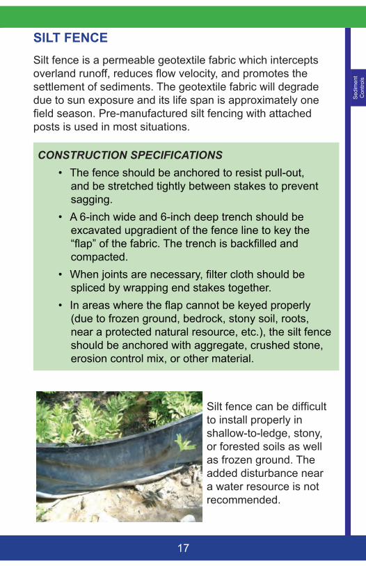
SILT FENCE Silt fence is a permeable geotextile fabric which intercepts overland runoff, reduces flow velocity, and promotes the settlement of sediments. The geotextile fabric will degrade due to sun exposure and its life span is approximately one field season. Pre-manufactured silt fencing with attached posts is used in most situations.
CONSTRUCTION SPECIFICATIONS• The fence should be anchored to resist pull-out,
and be stretched tightly between stakes to prevent sagging.
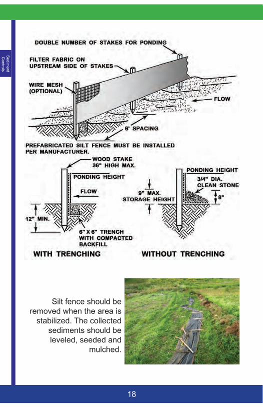
• A 6-inch wide and 6-inch deep trench should be excavated upgradient of the fence line to key the “flap” of the fabric. The trench is backfilled and compacted.
• When joints are necessary, filter cloth should be spliced by wrapping end stakes together.
• In areas where the flap cannot be keyed properly (due to frozen ground, bedrock, stony soil, roots, near a protected natural resource, etc.), the silt fence should be anchored with aggregate, crushed stone, erosion control mix, or other material.
Silt fence can be difficult to install properly in shallow-to-ledge, stony, or forested soils as well as frozen ground. The added disturbance near a water resource is not recommended.
Sedim
ent C
ontrols
18
Silt fence should be removed when the area is
stabilized. The collected sediments should be leveled, seeded and
mulched.
Sed
imen
t C
ontro
ls
19
EROSION CONTROL MIX BERM Berms of erosion control mix (ECM) are effective on frozen ground, outcrops of bedrock, and heavily rooted forested areas, or when other temporary erosion and sediment control measures are not practicable.
IMPORTANT NOTE:
A great source of erosion control mix is stump grindings. The soil within the root ball should not be removed before grinding as it adds structure to the media. See the Erosion Control Mix Mulch section for material specifications.
CONSTRUCTION SPECIFICATIONS• It may be necessary to cut, pack down or remove
tall grasses, brush or woody vegetation to avoid voids and bridges that allow the washing away of fine soil particles.
• The ECM berm should be a minimum of 12” high and a minimum of two feet wide. On longer or steeper slopes, the will need to be wider and higher.
• Berms composed of ECM can be reshaped when necessary.
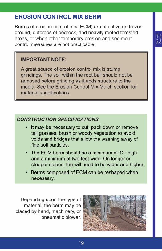
Depending upon the type of material, the berm may be
placed by hand, machinery, or pneumatic blower.
Sedim
ent C
ontrols
20
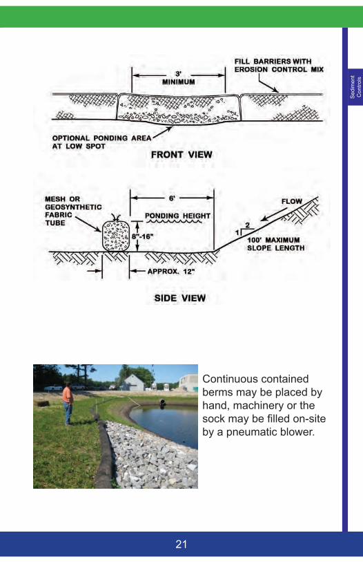
FILTER SOCKSA continuous contained berm or filter sock is a manufactured synthetic netting tube that is filled with erosion control mix, or other finely shredded organic material (i.e. coconut fiber or other). The netting prevents the displacement and loss of the organic filter material. Continuous contained berms work well in areas where trenching for a silt fence is not feasible such as on frozen ground or over pavement. A filter sock can be reshaped (if a vehicle drives over it).
Seeds may be added to the filler material for a permanent vegetation cover. Various manufactured products are available and installation should follow the manufacturer’s specifications and type of media.
CONSTRUCTION SPECIFICATIONS• A filter sock’s most effective use is for small
disturbed areas, as a perimeter protection around a soil stockpile, or a sediment barrier in low flow drainage swales or around drainage outlets and catchbasins.
• Full contact with the ground is critical to prevent short circuiting under the tube and the ground surface should be smooth and level. In wooded areas, protruding roots and debris may need to be removed; and in grassed areas, the grass needs to be either mowed or compressed down.
• Staking may be necessary on steep slopes.• Upon final stabilization, the tube can be cut open
and the material spread out onto the ground. The mesh material should be removed.
Sed
imen
t C
ontro
ls
21
Continuous contained berms may be placed by hand, machinery or the sock may be filled on-site by a pneumatic blower.
Sedim
ent C
ontrols
22
STONE CHECK DAMS Stone check dams are constructed across a swale or drainage ditch to reduce the flow velocity and erosive forces and to promote the deposit of sediments. Stone check dams are most important in channels with a slope greater than 6%. They are not effective for silts and clays. Other proprietary products are available and should be used and installed per the manufacturer’s guidelines.
IMPORTANT NOTE:
Check dams are intended for the settlement of sediments and flow velocity reduction. A ditch lining will be necessary for erosion control.
CONSTRUCTION SPECIFICATIONS • Check dams should be installed before runoff is
directed to the swale.• The area around each check dam should be free of
debris. • A stone check dam should be comprised of well-
graded crushed rock with a maximum size of 6 inches and a minimum stone size of 1 inch. Larger stones may be used on steep slopes.
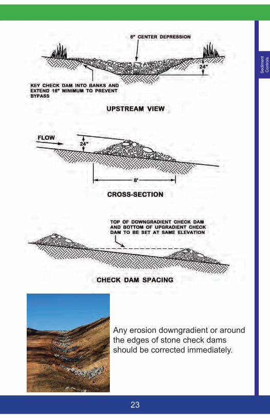
• The maximum height of a stone check dam should be 2 feet with a 6-inch depression at its center for overflow. The edges of the dam should be keyed onto the embankments to prevent side erosion.
• Mechanical placement followed by hand placement will be necessary to achieve a tight mass within the channel and to ensure that the center of the dam is lower than the edges.
• The check dams may be removed when the swale is stabilized with vegetation (95% coverage).
Sed
imen
t C
ontro
ls
23
Any erosion downgradient or around the edges of stone check dams should be corrected immediately.
Sedim
ent C
ontrols
24
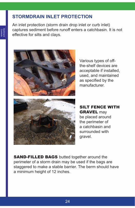
STORMDRAIN INLET PROTECTIONAn inlet protection (storm drain drop inlet or curb inlet) captures sediment before runoff enters a catchbasin. It is not effective for silts and clays.
Various types of off-the-shelf devices are acceptable if installed, used, and maintained as specified by the manufacturer.
SILTFENCEWITHGRAVEL may be placed around the perimeter of a catchbasin and surrounded with gravel.
SAND-FILLEDBAGSbutted together around the perimeter of a storm drain may be used if the bags are staggered to make a stable barrier. The berm should have a minimum height of 12 inches.
Sed
imen
t C
ontro
ls
25
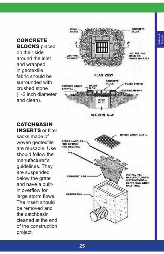
CONCRETEBLOCKS placed on their side around the inlet and wrapped in geotextile fabric should be surrounded with crushed stone (1-2 inch diameter and clean).
CATCHBASININSERTS or filter sacks made of woven geotextile are reusable. Use should follow the manufacturer’s guidelines. They are suspended below the grate and have a built-in overflow for large storm flows. The insert should be removed and the catchbasin cleaned at the end of the construction project.
Sedim
ent C
ontrols
26
HAY BALES Hay (or straw) bales should only be used as a sediment barrier for a small disturbance with a limited watershed. Their use may also be a simple and effective emergency measure for controlling unexpected sedimentation.
CONSTRUCTION SPECIFICATIONS • Hay bales should be installed so that the bindings
are oriented parallel to the ground to delay their deterioration (hay bales will not last through a construction season and will need to be replaced).
• The barrier should be entrenched a minimum depth of 4 inches. The gaps between bales should be chinked (filled by wedging) with hay to prevent the flow of water between the bales. For small areas or near a protected resource, trenching may not be necessary.
• At least two stakes per bale should be driven into the ground for anchoring. The first stake is driven toward the previous bale to force them together.
• After the bales are staked and chinked, the excavated soil should be backfilled and packed against the barrier to the ground level on the downhill side and 4 inches up the uphill side.
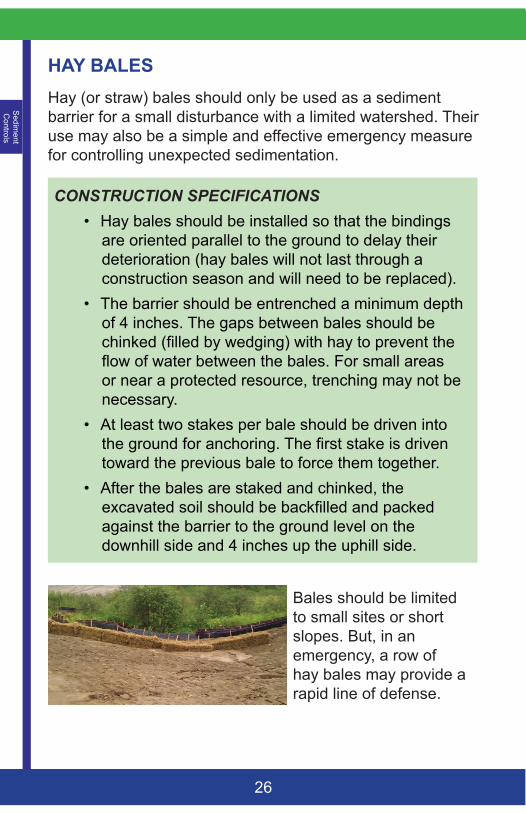
Bales should be limited to small sites or short slopes. But, in an emergency, a row of hay bales may provide a rapid line of defense.
Sed
imen
t C
onta
inm
ent
27
C – SEDIMENT CONTAINMENTA temporary sediment trap or basin intercepts and pools runoff for settlement; but it should be installed prior to any site disturbance and should always discharge to an area that is stable. As a general rule, sands and gravels settle rapidly, silt requires 24 hours or more; and clays may never settle.
COMPANION BMPs: Construction Dewatering, Sediment Barrier, Road Ditch Turnouts and Level Spreaders
IMPORTANT NOTE:
The containment area should not be removed before the area is fully stabilized. Regularly check for leakage, short-circuiting and overtopping. Inspect the receiving area for soil erosion or sedimentation. Diversion ditches may be necessary to direct runoff to the basin.
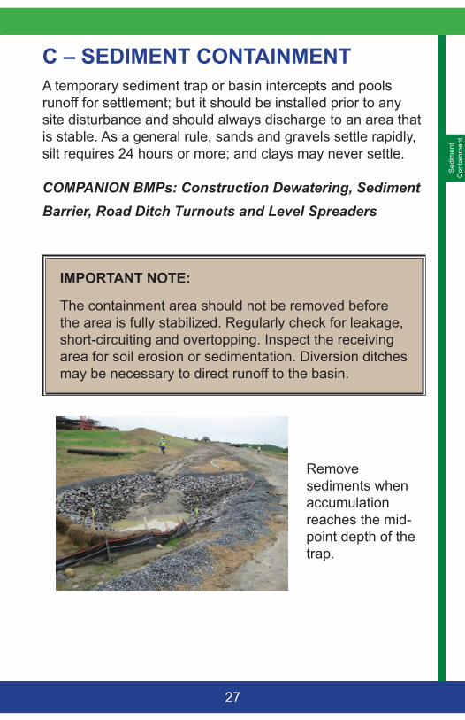
Remove sediments when accumulation reaches the mid-point depth of the trap.
Sedim
ent C
ontainment
28
SEDIMENT TRAPSA sediment trap can be above ground with a perimeter berm, within a natural depression, or in an excavated depression. The drainage area to a trap should be small, and the discharge should be directed to a stable, moderately flat (<5%) area with at least 25 feet of healthy vegetation. Sediment traps are not designed to work within a drainage way with high flow volumes or velocities.
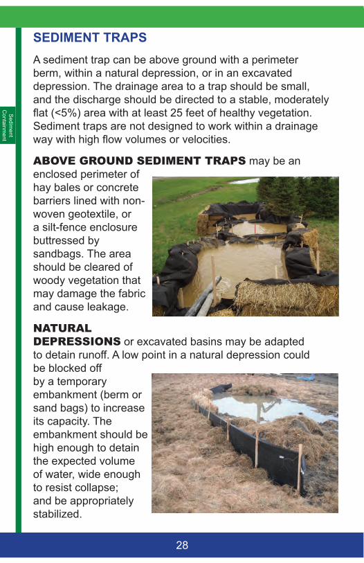
ABOVEGROUNDSEDIMENTTRAPS may be an enclosed perimeter of hay bales or concrete barriers lined with non-woven geotextile, or a silt-fence enclosure buttressed by sandbags. The area should be cleared of woody vegetation that may damage the fabric and cause leakage.
NATURALDEPRESSIONS or excavated basins may be adapted to detain runoff. A low point in a natural depression could be blocked off by a temporary embankment (berm or sand bags) to increase its capacity. The embankment should be high enough to detain the expected volume of water, wide enough to resist collapse; and be appropriately stabilized.
Sed
imen
t C
onta
inm
ent
29
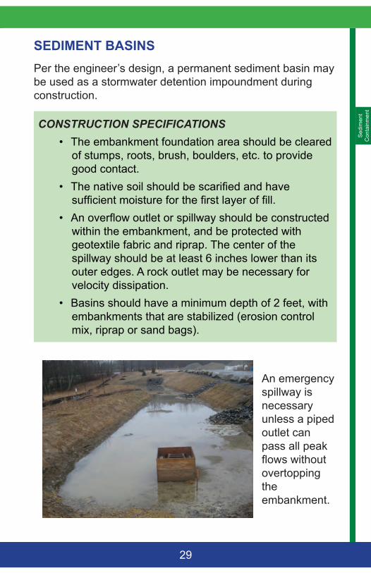
SEDIMENT BASINSPer the engineer’s design, a permanent sediment basin may be used as a stormwater detention impoundment during construction.
CONSTRUCTION SPECIFICATIONS • The embankment foundation area should be cleared
of stumps, roots, brush, boulders, etc. to provide good contact.
• The native soil should be scarified and have sufficient moisture for the first layer of fill.
• An overflow outlet or spillway should be constructed within the embankment, and be protected with geotextile fabric and riprap. The center of the spillway should be at least 6 inches lower than its outer edges. A rock outlet may be necessary for velocity dissipation.
• Basins should have a minimum depth of 2 feet, with embankments that are stabilized (erosion control mix, riprap or sand bags).
An emergency spillway is necessary unless a piped outlet can pass all peak flows without overtopping the embankment.
Sedim
ent C
ontainment
30
CONSTRUCTION SPECIFICATIONS• The fill material should be free of roots, frozen soil
and stones. Fill should be placed in 6-inch lifts before compaction to insure a good bond between layers. Lenses, pockets, streaks or uncompacted layers of material are not acceptable. If materials of varying texture should be used, the more impervious material should be placed in the center or upstream of the embankment.
• The moisture content of the fill material should be adequate for compaction.
• The top of the embankment should be at least 18-inches above the crest of the riser.
• Fill adjacent to structures, pipe conduits, and anti-seep collars should be compacted to 95% Standard Proctor. Fill adjacent to poured in-place concrete structures should not be compacted until the concrete has gained the strength to support the load.
• A piped outlet can be fitted to a basin instead of an overflow spillway. The capacity of the outlet should be adequate to discharge anticipated flows.
• The perforated riser pipe should have its top 2/3rd perforated or slotted up to the top six (6) inches of the barrel. The outlet should be surrounded with geotextile and a cone of gravel to filter the fine sediment particles.
• The riser should be weighted by a base (i.e. 12- inch thick concrete block or ¼-inch thick steel plate) and gravel to prevent flotation.
• All pipe joints should be watertight using couplings, gaskets, caulking, or welding.
Sed
imen
t C
onta
inm
ent
31
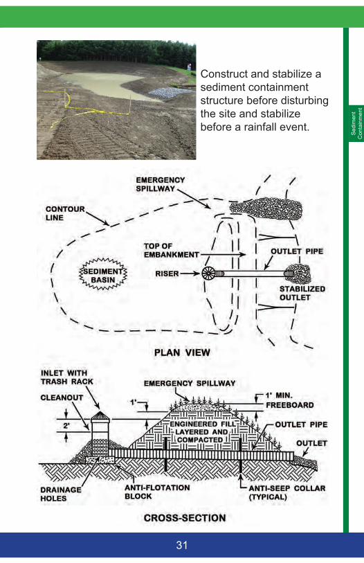
Construct and stabilize a sediment containment structure before disturbing the site and stabilize before a rainfall event.
Sedim
ent C
ontainment
32
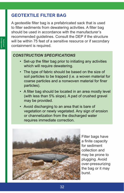
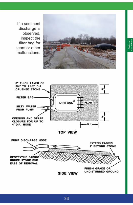
GEOTEXTILE FILTER BAGA geotextile filter bag is a prefabricated sack that is used to filter sediments from dewatering activities. A filter bag should be used in accordance with the manufacturer’s recommended guidelines. Consult the DEP if the structure will be within 75 feet of a sensitive resource or if secondary containment is required.
CONSTRUCTION SPECIFICATIONS• Set-up the filter bag prior to initiating any activities
which will require dewatering.• The type of fabric should be based on the size of
soil particles to be trapped (i.e. a woven material for coarse particles and a nonwoven material for finer particles).
• A filter bag should be located in an area mostly level (with less than 5% slope). A pad of crushed gravel may be provided.
• Avoid discharging to an area that is bare of vegetation or newly vegetated. Any sign of erosion or channelization from the discharged water requires immediate correction.
Filter bags have a finite capacity for sediment collection and may be prone to plugging. Avoid over-pressurizing the bag or it may burst.
Sed
imen
t C
onta
inm
ent
33
If a sediment discharge is
observed, inspect the
filter bag for tears or other malfunctions.
Sedim
ent C
ontainment
34
FLOCCULANTS (POLYMERS)Flocculants (polymer or anionic polyacrylamide) produce a chemically charged non-toxic substance that binds soil particles to each other. With flocculants, a soil is resistant to erosion, the settling time in water is decreased, and the soil’s soil pore volume, permeability, and infiltration are increased. Flocculants are particularly effective on silt and clays.
Flocculants are available in four types of media (powder, liquid, emulsion or gel block). The powder, liquid, and emulsion media can be applied directly for immediate stabilization. Gel blocks are used for the settlement of suspended soil particles in flowing water.
The supplier’s recommendations are important to follow for success, and soil and water testing is critical to select the correct flocculants, additives, dosing rate, and dosing method. Be aware that there are many available flocculants that may not have third-party approval for toxicity to aquatic life.
CONSTRUCTION SPECIFICATIONS• Flocculants should be applied above a sediment
trap or basin. Any remaining particulates in a treated discharge require immediate correction.
• Consult with the DEP if the treated runoff is to enter directly into a protected natural resource.
• As a liquid or in a powder, flocculants can be used for dust control or for stabilization before vegetation can establish. Reapplication will not be necessary if the site is seeded and mulched as the polymers will reduce the loss of seeds and fertilizer.
• Pools and riffles within a drainage channel will ensure mixing and contact time with a gel block to promote the settlement of soil particulates.
Mul
chin
g
35
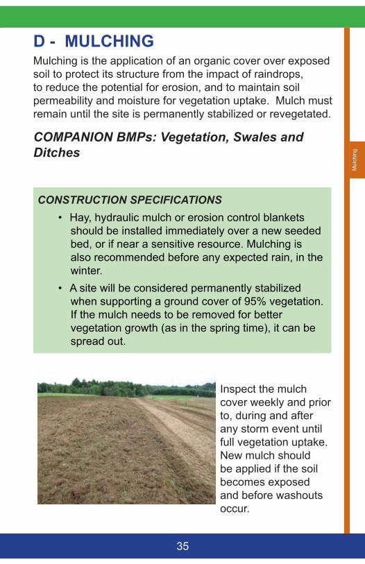
D - MULCHINGMulching is the application of an organic cover over exposed soil to protect its structure from the impact of raindrops, to reduce the potential for erosion, and to maintain soil permeability and moisture for vegetation uptake. Mulch must remain until the site is permanently stabilized or revegetated.
COMPANION BMPs: Vegetation, Swales and Ditches
CONSTRUCTION SPECIFICATIONS• Hay, hydraulic mulch or erosion control blankets
should be installed immediately over a new seeded bed, or if near a sensitive resource. Mulching is also recommended before any expected rain, in the winter.
• A site will be considered permanently stabilized when supporting a ground cover of 95% vegetation. If the mulch needs to be removed for better vegetation growth (as in the spring time), it can be spread out.
Inspect the mulch cover weekly and prior to, during and after any storm event until full vegetation uptake. New mulch should be applied if the soil becomes exposed and before washouts occur.
Mulching
36
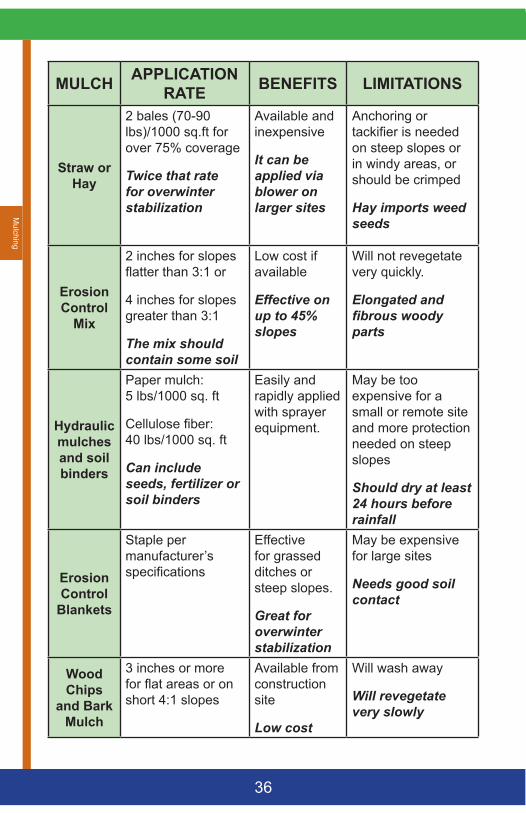
MULCH APPLICATION RATE BENEFITS LIMITATIONS
Straw or Hay
2 bales (70-90 lbs)/1000 sq.ft for over 75% coverage
Twice that rate for overwinter stabilization
Available and inexpensive
It can be applied via blower on larger sites
Anchoring or tackifier is needed on steep slopes or in windy areas, or should be crimped
Hay imports weed seeds
Erosion Control
Mix
2 inches for slopes flatter than 3:1 or
4 inches for slopes greater than 3:1
The mix should contain some soil
Low cost if available
Effective on up to 45% slopes
Will not revegetate very quickly.
Elongated and fibrous woody parts
Hydraulic mulches and soil binders
Paper mulch: 5 lbs/1000 sq. ft
Cellulose fiber: 40 lbs/1000 sq. ft
Can include seeds, fertilizer or soil binders
Easily and rapidly applied with sprayer equipment.
May be too expensive for a small or remote site and more protection needed on steep slopes
Should dry at least 24 hours before rainfall
Erosion Control
Blankets
Staple per manufacturer’s specifications
Effective for grassed ditches or steep slopes.
Great for overwinter stabilization
May be expensive for large sites
Needs good soil contact
Wood Chips
and Bark Mulch
3 inches or more for flat areas or on short 4:1 slopes
Available from construction site
Low cost
Will wash away
Will revegetate very slowly
Mul
chin
g
37
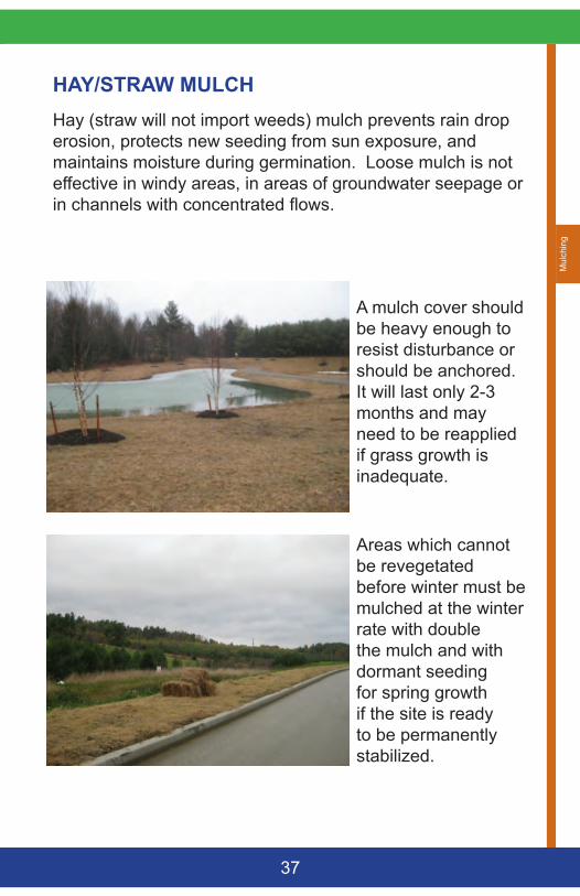
HAY/STRAW MULCHHay (straw will not import weeds) mulch prevents rain drop erosion, protects new seeding from sun exposure, and maintains moisture during germination. Loose mulch is not effective in windy areas, in areas of groundwater seepage or in channels with concentrated flows.
A mulch cover should be heavy enough to resist disturbance or should be anchored. It will last only 2-3 months and may need to be reapplied if grass growth is inadequate.
Areas which cannot be revegetated before winter must be mulched at the winter rate with double the mulch and with dormant seeding for spring growth if the site is ready to be permanently stabilized.
Mulching
38
CONSTRUCTION SPECIFICATIONS• Temporary mulch should be applied to areas that
will not be actively worked for more than 14 days (7 days in sensitive areas).
• Application rate should be 2 bales (70-90 pounds) per 1000 square feet or 1.5 to 2 tons (90-100 bales) per acre and must be evenly distributed.
• Provide a mulch cover to soil stockpiles. • Anchoring should be provided in areas with strong
wind or on slopes greater than 5%. • Hay mulch should be limited to slopes flatter than
2:1 unless short (less than 10 feet), and in non-seepage areas. Another measure should be used on steeper slopes with a high runoff potential.
• Anchoring can be accomplished by punching, crimping the mulch into the soil or tracking with a punch-roller or a knife blade roller. Walking and punching with a spade or shovel may be practicable on very small sites.
• Peg and twine or netting should be installed per the manufacturer’s recommendations. Non-biodegradable plastic netting should be removed after the site is revegetated.
• Apply additional mulch if not revegetated with 95% grass uptake.
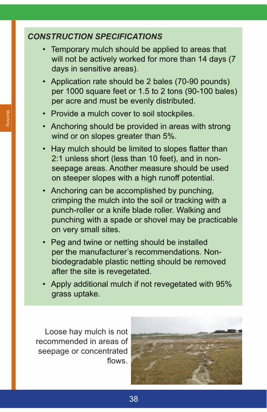
Loose hay mulch is not recommended in areas of seepage or concentrated
flows.
Mul
chin
g
39
EROSION CONTROL BLANKETSAn erosion control blanket (or mat) is a machine-produced blanket of organic fiber, sewn into a biodegradable mesh (or geo-web cellular structure for more reinforcement). Organic mats are available as jute, excelsior wood fiber, coconut fiber, straw, and others.
Blankets are designed to retain the soil moisture and maintain a constant temperature for seed germination; and they are most useful where hay cannot sustain wind or water disturbance or when the site is to overwinter. An erosion control blanket could be used in the following conditions:
• Vegetated waterways and ditches; but not in areas of groundwater seepage
• Steep slopes (15% or greater and up to 2:1)• In protected natural areas• On areas that may be slow to revegetate• For overwinter stabilization (November 1 - April 15)
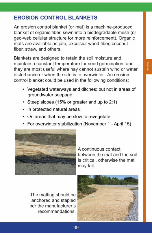
A continuous contact between the mat and the soil is critical, otherwise the mat may fail.
The matting should be anchored and stapled
per the manufacturer’s recommendations.
Mulching
40
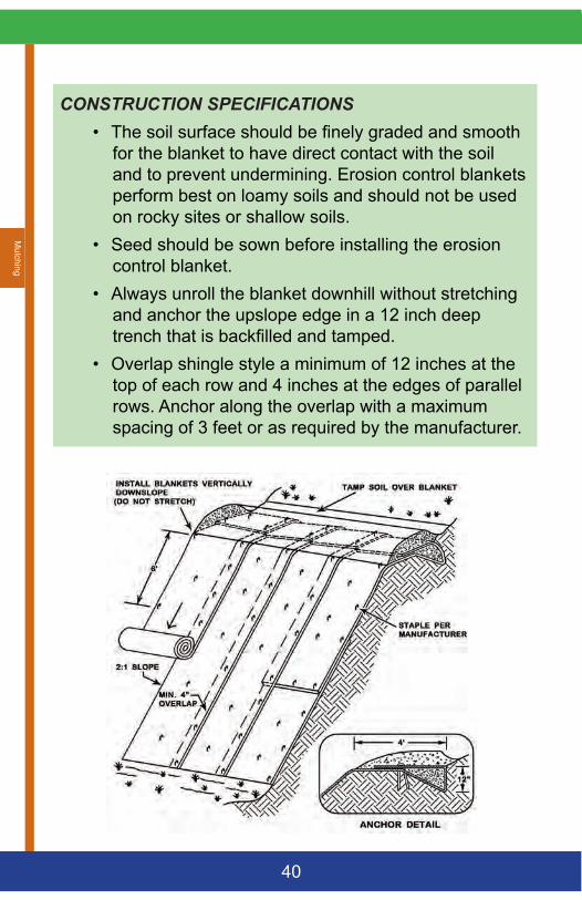
CONSTRUCTION SPECIFICATIONS• The soil surface should be finely graded and smooth
for the blanket to have direct contact with the soil and to prevent undermining. Erosion control blankets perform best on loamy soils and should not be used on rocky sites or shallow soils.
• Seed should be sown before installing the erosion control blanket.
• Always unroll the blanket downhill without stretching and anchor the upslope edge in a 12 inch deep trench that is backfilled and tamped.
• Overlap shingle style a minimum of 12 inches at the top of each row and 4 inches at the edges of parallel rows. Anchor along the overlap with a maximum spacing of 3 feet or as required by the manufacturer.
Mul
chin
g
41
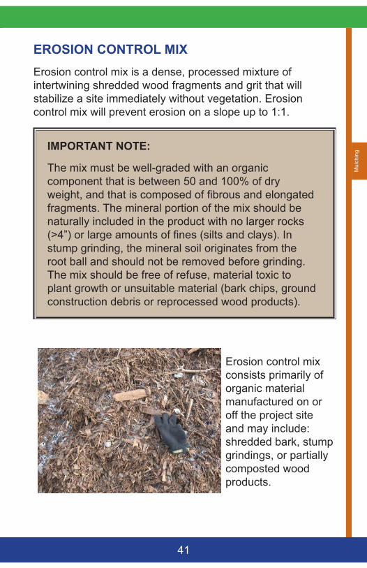
EROSION CONTROL MIXErosion control mix is a dense, processed mixture of intertwining shredded wood fragments and grit that will stabilize a site immediately without vegetation. Erosion control mix will prevent erosion on a slope up to 1:1.
IMPORTANT NOTE:
The mix must be well-graded with an organic component that is between 50 and 100% of dry weight, and that is composed of fibrous and elongated fragments. The mineral portion of the mix should be naturally included in the product with no larger rocks (>4”) or large amounts of fines (silts and clays). In stump grinding, the mineral soil originates from the root ball and should not be removed before grinding. The mix should be free of refuse, material toxic to plant growth or unsuitable material (bark chips, ground construction debris or reprocessed wood products).
Erosion control mix consists primarily of organic material manufactured on or off the project site and may include: shredded bark, stump grindings, or partially composted wood products.
Mulching
42
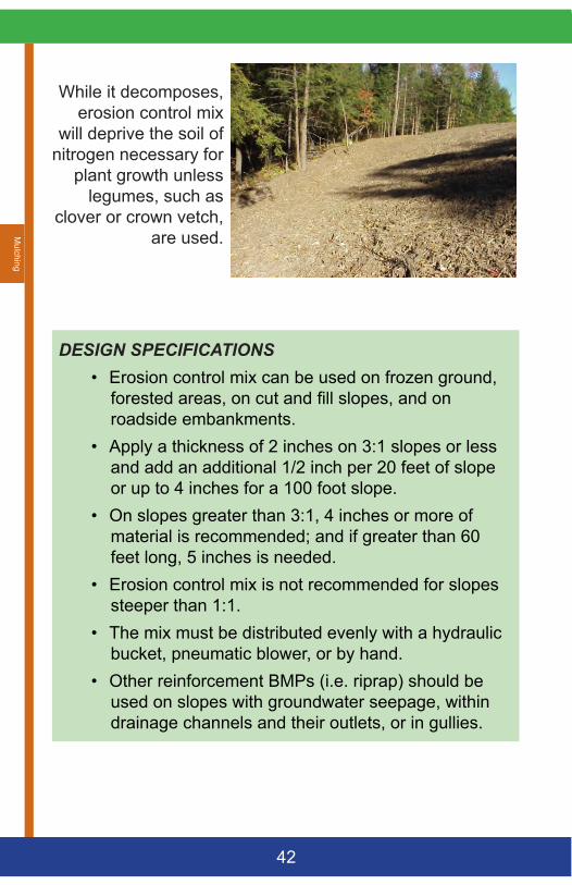
While it decomposes, erosion control mix
will deprive the soil of nitrogen necessary for
plant growth unless legumes, such as
clover or crown vetch, are used.
DESIGN SPECIFICATIONS• Erosion control mix can be used on frozen ground,
forested areas, on cut and fill slopes, and on roadside embankments.
• Apply a thickness of 2 inches on 3:1 slopes or less and add an additional 1/2 inch per 20 feet of slope or up to 4 inches for a 100 foot slope.
• On slopes greater than 3:1, 4 inches or more of material is recommended; and if greater than 60 feet long, 5 inches is needed.
• Erosion control mix is not recommended for slopes steeper than 1:1.
• The mix must be distributed evenly with a hydraulic bucket, pneumatic blower, or by hand.
• Other reinforcement BMPs (i.e. riprap) should be used on slopes with groundwater seepage, within drainage channels and their outlets, or in gullies.
Mul
chin
g
43
HYDRAULIC MULCHHydraulic mulch is a mixture of mulch (paper, cellulose and wood fiber), binder, and water that is sprayed with or without seeds and fertilizer to stabilize a soil surface. It may be used as a ‘tackifier’ to secure hay mulch in windy areas. Consult the manufacturer or applicator for more information on the use and application of each specific product.
CONSTRUCTION SPECIFICATIONS• Hydraulic mulch should be applied within one week
of final grading. Avoid applying on windy days. Higher rates of mulching should be used on areas subject to wind.
• Apply when no rain is predicted for a few days as the mulch binder has a curing time of about 24 hours. Low temperatures will also slow down the curing time.
• Apply a paper hydraulic mulch at a rate of 5 lbs./1000 square feet or as directed by the manufacturer.
• Apply a cellulose fiber mulch mixture at a rate of no less than 40 lbs./1000 square feet or as directed by the manufacturer.
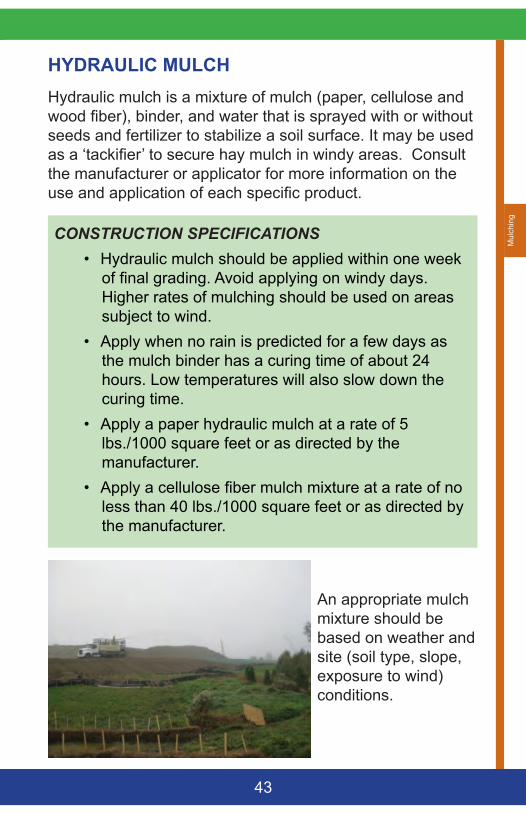
An appropriate mulch mixture should be based on weather and site (soil type, slope, exposure to wind) conditions.
Vegetation
44
E - VEGETATIONThe most permanent, simple and inexpensive stabilization measure is by re-vegetating a disturbance. Vegetation is natural, regenerating; and will protect the soil surface, promotes infiltration and reduces flow velocity. Seeding and mulching should be applied as soon as possible upon final grading or as a temporary cover if final grading will not occur before 14 days. The vegetation’s effectiveness will vary with the underlying soils, slope, and runoff volume and velocity.
IMPORTANT NOTES:
• Long slopes steeper than 2:1 cannot support vegetation unless the soil has good structure and no upgradient watershed.
• All newly seeded areas should be mulched and anchored.
• Deeply rooted plants will be more effective at stabilizing slopes. Incorporate a variety of plants, shrubs, or trees that are native to Maine and require little maintenance.
• Apply limestone and fertilizer only if necessary to prevent impact to surface water or groundwater.
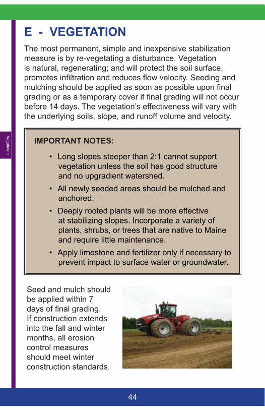
Seed and mulch should be applied within 7 days of final grading. If construction extends into the fall and winter months, all erosion control measures should meet winter construction standards.
Vege
tatio
n
45
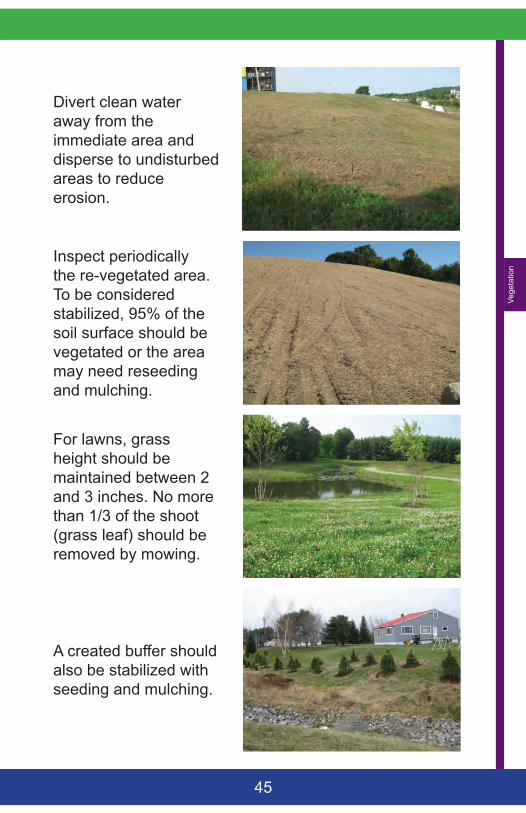
Divert clean water away from the immediate area and disperse to undisturbed areas to reduce erosion.
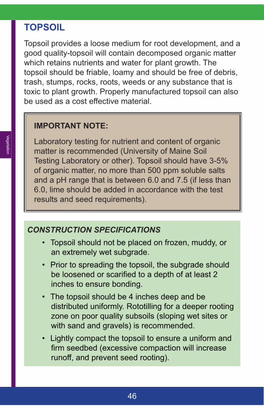
Inspect periodically the re-vegetated area. To be considered stabilized, 95% of the soil surface should be vegetated or the area may need reseeding and mulching.
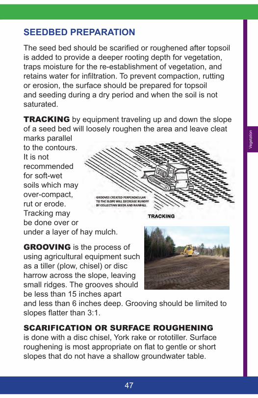
For lawns, grass height should be maintained between 2 and 3 inches. No more than 1/3 of the shoot (grass leaf) should be removed by mowing.
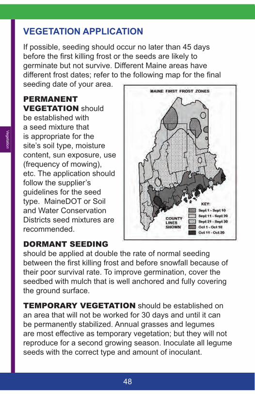
A created buffer should also be stabilized with seeding and mulching.
Vegetation
46
TOPSOILTopsoil provides a loose medium for root development, and a good quality-topsoil will contain decomposed organic matter which retains nutrients and water for plant growth. The topsoil should be friable, loamy and should be free of debris, trash, stumps, rocks, roots, weeds or any substance that is toxic to plant growth. Properly manufactured topsoil can also be used as a cost effective material.
IMPORTANT NOTE:
Laboratory testing for nutrient and content of organic matter is recommended (University of Maine Soil Testing Laboratory or other). Topsoil should have 3-5% of organic matter, no more than 500 ppm soluble salts and a pH range that is between 6.0 and 7.5 (if less than 6.0, lime should be added in accordance with the test results and seed requirements).
CONSTRUCTION SPECIFICATIONS• Topsoil should not be placed on frozen, muddy, or
an extremely wet subgrade. • Prior to spreading the topsoil, the subgrade should
be loosened or scarified to a depth of at least 2 inches to ensure bonding.
• The topsoil should be 4 inches deep and be distributed uniformly. Rototilling for a deeper rooting zone on poor quality subsoils (sloping wet sites or with sand and gravels) is recommended.
• Lightly compact the topsoil to ensure a uniform and firm seedbed (excessive compaction will increase runoff, and prevent seed rooting).
Vege
tatio
n
47
SEEDBED PREPARATIONThe seed bed should be scarified or roughened after topsoil is added to provide a deeper rooting depth for vegetation, traps moisture for the re-establishment of vegetation, and retains water for infiltration. To prevent compaction, rutting or erosion, the surface should be prepared for topsoil and seeding during a dry period and when the soil is not saturated.
TRACKING by equipment traveling up and down the slope of a seed bed will loosely roughen the area and leave cleat marks parallel to the contours. It is not recommended for soft-wet soils which may over-compact, rut or erode. Tracking may be done over or under a layer of hay mulch.
GROOVING is the process of using agricultural equipment such as a tiller (plow, chisel) or disc harrow across the slope, leaving small ridges. The grooves should be less than 15 inches apart and less than 6 inches deep. Grooving should be limited to slopes flatter than 3:1.
SCARIFICATIONORSURFACEROUGHENING is done with a disc chisel, York rake or rototiller. Surface roughening is most appropriate on flat to gentle or short slopes that do not have a shallow groundwater table.
Vegetation
48
VEGETATION APPLICATIONIf possible, seeding should occur no later than 45 days before the first killing frost or the seeds are likely to germinate but not survive. Different Maine areas have different frost dates; refer to the following map for the final seeding date of your area.
PERMANENTVEGETATION should be established with a seed mixture that is appropriate for the site’s soil type, moisture content, sun exposure, use (frequency of mowing), etc. The application should follow the supplier’s guidelines for the seed type. MaineDOT or Soil and Water Conservation Districts seed mixtures are recommended.
DORMANTSEEDING should be applied at double the rate of normal seeding between the first killing frost and before snowfall because of their poor survival rate. To improve germination, cover the seedbed with mulch that is well anchored and fully covering the ground surface.
TEMPORARYVEGETATION should be established on an area that will not be worked for 30 days and until it can be permanently stabilized. Annual grasses and legumes are most effective as temporary vegetation; but they will not reproduce for a second growing season. Inoculate all legume seeds with the correct type and amount of inoculant.
Vege
tatio
n
49
TEMPORARY SEED APPLICATION GUIDELINESSEED Lb /
AcreLb / 1,000 SF
Seeding Dates
Notes
Winter Rye 112 2.6 8/15 - 10/1
Select hardy species such as Aroostook Rye
Oats 80 1.8 4/1 - 7/1 8/15 - 9/15
Best for spring seeding. Fall seeding will die over the winter.
Annual Rye Grass
40 0.9 4/1 - 7/1 Grows quickly but is of short duration. With mulch, seeding may be done throughout growing season.
Sudangrass 40 0.9 5/15 – 8/15
Good growth during periods of hot weather.
Perennial Rye Grass
40 0.9 8/15 – 9/15
Good cover, longer lasting than annual rye grass. Mulching will allow seeding throughout growing season.
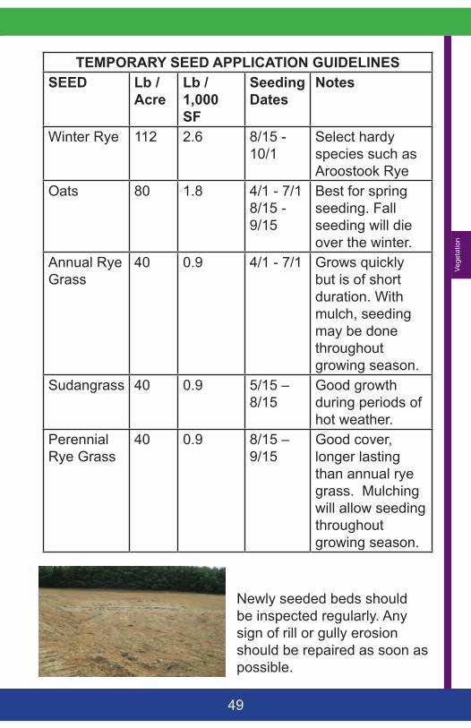
Newly seeded beds should be inspected regularly. Any sign of rill or gully erosion should be repaired as soon as possible.
Vegetation
50
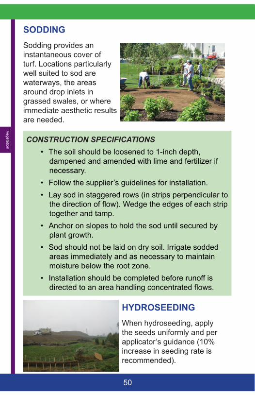
SODDINGSodding provides an instantaneous cover of turf. Locations particularly well suited to sod are waterways, the areas around drop inlets in grassed swales, or where immediate aesthetic results are needed.
CONSTRUCTION SPECIFICATIONS• The soil should be loosened to 1-inch depth,
dampened and amended with lime and fertilizer if necessary.
• Follow the supplier’s guidelines for installation. • Lay sod in staggered rows (in strips perpendicular to
the direction of flow). Wedge the edges of each strip together and tamp.
• Anchor on slopes to hold the sod until secured by plant growth.
• Sod should not be laid on dry soil. Irrigate sodded areas immediately and as necessary to maintain moisture below the root zone.
• Installation should be completed before runoff is directed to an area handling concentrated flows.
HYDROSEEDINGWhen hydroseeding, apply the seeds uniformly and per applicator’s guidance (10% increase in seeding rate is recommended).
Slo
pes
51
F - SLOPESTo be effective, slope stabilization and reinforcement should be adapted to the soil type, angle and length of the slope, presence of surface or groundwater, depth to bedrock, etc. Consultation with a civil engineer is advised for slopes that are over six feet, steeper than 1.5:1 grade, on unstable soils, with groundwater seeps, or where a structure is located near the top of the bank.
COMPANION BMPs: RIPRAP, MULCHING, SEDIMENT BARRIERS AND VEGETATION
Approximate slope conversions Slopes that will be
revegetated should be no steeper than 2:1. Where the slope is to be mowed, the slope should be no steeper than 3:1 (4:1 is preferred for larger mowing equipment).
Percent Slope
Slope ratio Degrees
100% 1:1 45°50% 2:1 27°33% 3:1 16°25% 4:1 12°10% 10:1 5°
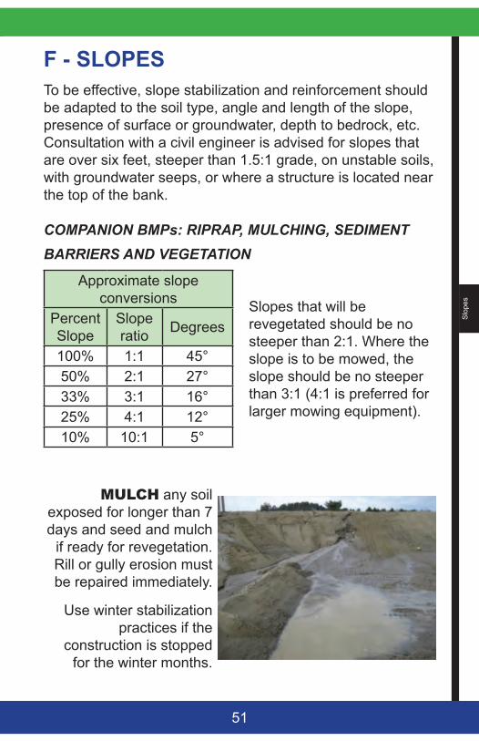
MULCH any soil exposed for longer than 7 days and seed and mulch
if ready for revegetation. Rill or gully erosion must be repaired immediately.
Use winter stabilization practices if the
construction is stopped for the winter months.
Slopes
52
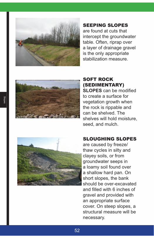
SEEPINGSLOPESare found at cuts that intercept the groundwater table. Often, riprap over a layer of drainage gravel is the only appropriate stabilization measure.
SOFTROCK(SEDIMENTARY) SLOPES can be modified to create a surface for vegetation growth when the rock is rippable and can be shelved. The shelves will hold moisture, seed, and mulch.
SLOUGHINGSLOPESare caused by freeze/thaw cycles in silty and clayey soils, or from groundwater seeps in a loamy soil found over a shallow hard pan. On short slopes, the bank should be over-excavated and filled with 6 inches of gravel and provided with an appropriate surface cover. On steep slopes, a structural measure will be necessary.
Slo
pes
53
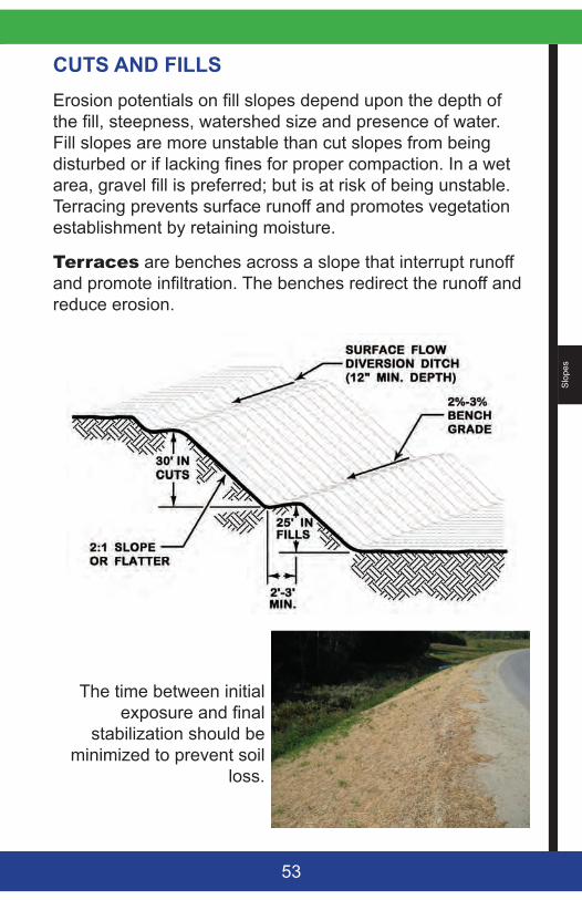
CUTS AND FILLSErosion potentials on fill slopes depend upon the depth of the fill, steepness, watershed size and presence of water. Fill slopes are more unstable than cut slopes from being disturbed or if lacking fines for proper compaction. In a wet area, gravel fill is preferred; but is at risk of being unstable. Terracing prevents surface runoff and promotes vegetation establishment by retaining moisture.
Terraces are benches across a slope that interrupt runoff and promote infiltration. The benches redirect the runoff and reduce erosion.
The time between initial exposure and final
stabilization should be minimized to prevent soil
loss.
Slopes
54
CONSTRUCTION SPECIFICATIONS• Divert clean water away from the construction area
and disperse to an undisturbed buffer or swale.• For a fill slope, the native area should be cleared,
grubbed, and scarified to a 3-inch depth. When working in below freezing temperatures, the ground should be scarified immediately before adding fill.
• The fill material should be free of brush, rocks, or roots, and should not include frozen, soft or mucky material.
• The fill should be placed and compacted in 8-inch lifts to reduce lenses of loose soil.
• When filling or cutting into a long slope (greater than 20 feet), benches (or terraces) should be provided to direct runoff away from the face of the slope. The number of benches should be based upon the erodibility of the soil, steepness of the slope, and presence of groundwater seeps.
• Any slope disturbance should be permanently stabilized within 7 days or intermediate stabilization measures should be taken.
Slo
pes
55
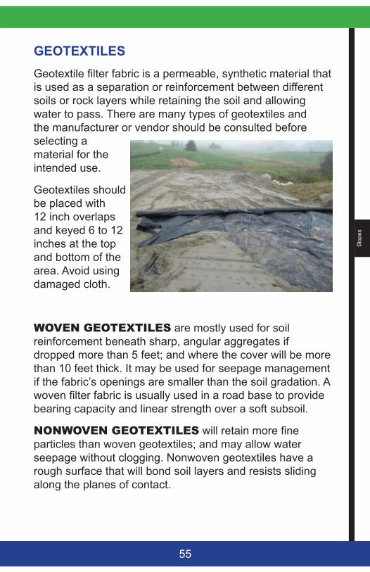
GEOTEXTILESGeotextile filter fabric is a permeable, synthetic material that is used as a separation or reinforcement between different soils or rock layers while retaining the soil and allowing water to pass. There are many types of geotextiles and the manufacturer or vendor should be consulted before selecting a material for the intended use.
Geotextiles should be placed with 12 inch overlaps and keyed 6 to 12 inches at the top and bottom of the area. Avoid using damaged cloth.
WOVENGEOTEXTILES are mostly used for soil reinforcement beneath sharp, angular aggregates if dropped more than 5 feet; and where the cover will be more than 10 feet thick. It may be used for seepage management if the fabric’s openings are smaller than the soil gradation. A woven filter fabric is usually used in a road base to provide bearing capacity and linear strength over a soft subsoil.
NONWOVENGEOTEXTILES will retain more fine particles than woven geotextiles; and may allow water seepage without clogging. Nonwoven geotextiles have a rough surface that will bond soil layers and resists sliding along the planes of contact.
Slopes
56
RIPRAPRiprap is used for structural support when a slope cannot be vegetated due to length or steepness of the slope, groundwater or surface water seepage, poor soil conditions, flowing water, etc. On a long slope, larger stones are used and placed at the bottom of the embankment and gradually grading down to smaller stones toward the top
A riprap stabilization project is composed of three sections:
• The surface armor layer of rough, angular rocks. • The filter layer (a sand and gravel layer and/or a
geotextile fabric) that may also support the stones against settlement, allows groundwater to drain through the structure, and prevents the soil beneath from being washed through the armor layer.
• The toe protection that reinforce the slope and prevents movement of the riprap. It is usually anchored in a trench at the toe of the slope.
IMPORTANT NOTE:
The riprap should be well graded with an average stone size described as the D50 which refers to the diameter of stone for which 50% of rocks will be smaller and 50% will be larger. This allows for a mixture composed primarily of the larger stone sizes; but with a sufficient number of the small rocks that fill the voids. The diameter of the largest stone size in such a mixture should be 1.5 times the D50 size. Refer to MaineDOT specifications for more information on standard types of riprap. At times, it may be difficult to obtain a rock mix with a specific D50 gradation. In these cases, use stones large enough so water or gravity won’t move them and fill the voids with smaller rocks.
Slo
pes
57
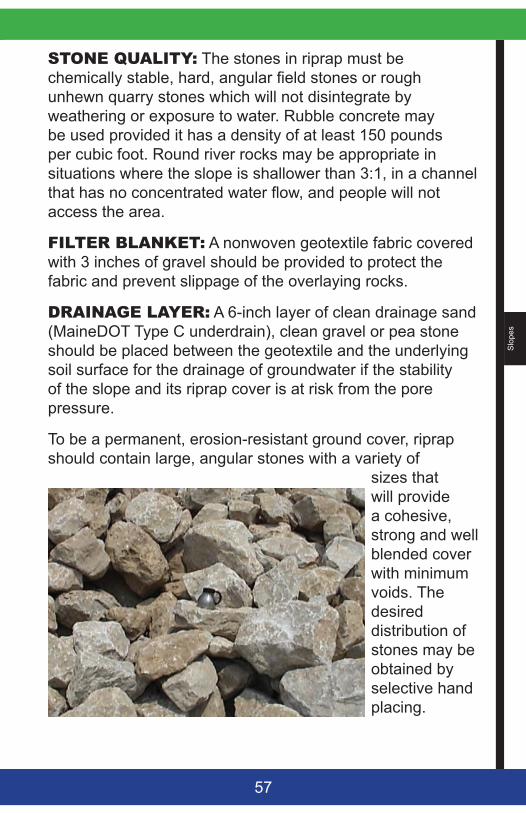
STONEQUALITY: The stones in riprap must be chemically stable, hard, angular field stones or rough unhewn quarry stones which will not disintegrate by weathering or exposure to water. Rubble concrete may be used provided it has a density of at least 150 pounds per cubic foot. Round river rocks may be appropriate in situations where the slope is shallower than 3:1, in a channel that has no concentrated water flow, and people will not access the area.
FILTERBLANKET: A nonwoven geotextile fabric covered with 3 inches of gravel should be provided to protect the fabric and prevent slippage of the overlaying rocks.
DRAINAGELAYER: A 6-inch layer of clean drainage sand (MaineDOT Type C underdrain), clean gravel or pea stone should be placed between the geotextile and the underlying soil surface for the drainage of groundwater if the stability of the slope and its riprap cover is at risk from the pore pressure.
To be a permanent, erosion-resistant ground cover, riprap should contain large, angular stones with a variety of
sizes that will provide a cohesive, strong and well blended cover with minimum voids. The desired distribution of stones may be obtained by selective hand placing.
Slopes
58
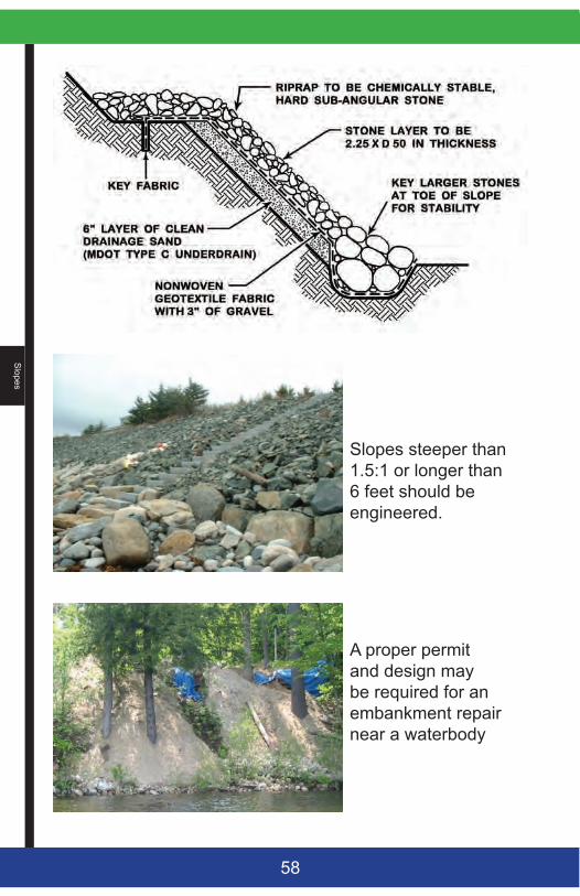
Slopes steeper than 1.5:1 or longer than 6 feet should be engineered.
A proper permit and design may be required for an embankment repair near a waterbody
Slo
pes
59
CONSTRUCTION SPECIFICATIONS • Any fill material should be well graded and should
be compacted to a density approximating that of the undisturbed material nearby or to 95% Standard Proctor Density.
• Entrench the toe of the riprap for structural support and use larger rocks.
• If a drainage layer is necessary to control groundwater seepage, approximately 6 inches of granular fill should be spread uniformly over the native soils. A nonwoven geotextile filter fabric may be placed directly on the prepared slope in situations where groundwater is not an issue. For more protection, provide both the drainage layer and the geotextile. The permeability of the filter fabric should be higher than the native material for the seepage to pass freely.
• When large stones are used for surface armoring (12 inches or greater), provide a 3-4-inch layer of gravel (¾ inch washed stone) to distribute the load, protect the fabric from degradation and to provide interfacial contact.
• The riprap should never be placed in layers nor dumped, as it segregates the various stone sizes and may disturb the underlying material. Final hand placement may be necessary to achieve the required grades.
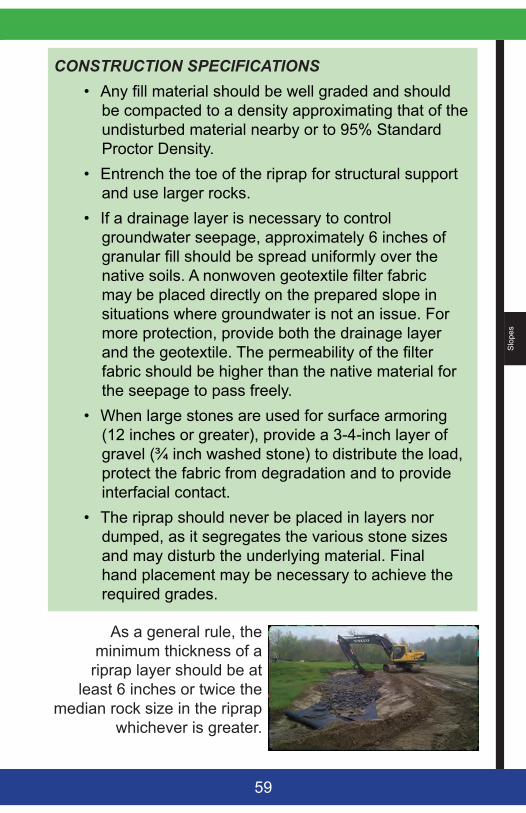
As a general rule, the minimum thickness of a
riprap layer should be at least 6 inches or twice the
median rock size in the riprap whichever is greater.
Slopes
60
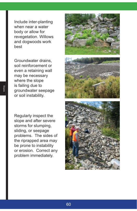
Include inter-planting when near a water body or allow for revegetation. Willows and dogwoods work best
Groundwater drains, soil reinforcement or even a retaining wall may be necessary where the slope is failing due to groundwater seepage or soil instability.
Regularly inspect the slope and after severe storms for slumping, sliding, or seepage problems. The sides of the riprapped area may be prone to instability or erosion. Correct any problem immediately.
Slo
pes
61
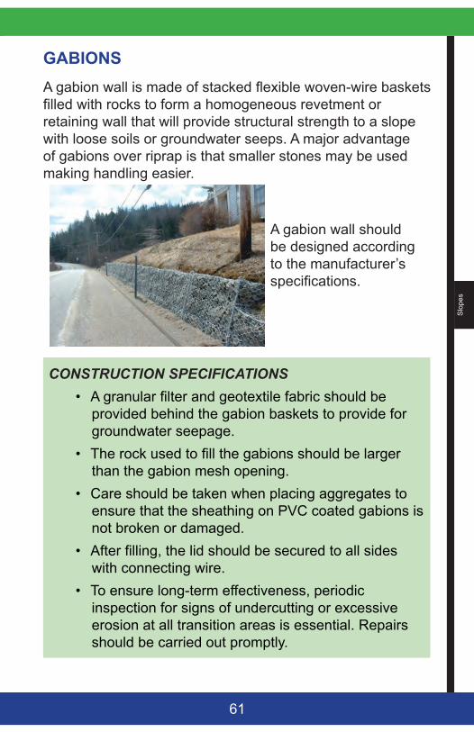
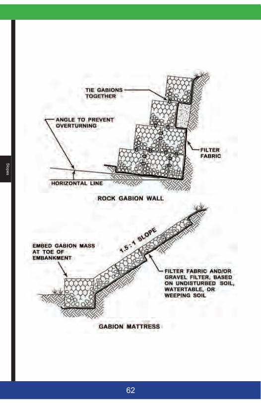
GABIONSA gabion wall is made of stacked flexible woven-wire baskets filled with rocks to form a homogeneous revetment or retaining wall that will provide structural strength to a slope with loose soils or groundwater seeps. A major advantage of gabions over riprap is that smaller stones may be used making handling easier.
A gabion wall should be designed according to the manufacturer’s specifications.
CONSTRUCTION SPECIFICATIONS • A granular filter and geotextile fabric should be
provided behind the gabion baskets to provide for groundwater seepage.
• The rock used to fill the gabions should be larger than the gabion mesh opening.
• Care should be taken when placing aggregates to ensure that the sheathing on PVC coated gabions is not broken or damaged.
• After filling, the lid should be secured to all sides with connecting wire.
• To ensure long-term effectiveness, periodic inspection for signs of undercutting or excessive erosion at all transition areas is essential. Repairs should be carried out promptly.
Slopes
62
Slo
pes
63
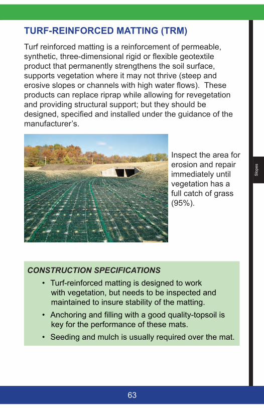
TURF-REINFORCED MATTING (TRM) Turf reinforced matting is a reinforcement of permeable, synthetic, three-dimensional rigid or flexible geotextile product that permanently strengthens the soil surface, supports vegetation where it may not thrive (steep and erosive slopes or channels with high water flows). These products can replace riprap while allowing for revegetation and providing structural support; but they should be designed, specified and installed under the guidance of the manufacturer’s.
Inspect the area for erosion and repair immediately until vegetation has a full catch of grass (95%).
CONSTRUCTION SPECIFICATIONS• Turf-reinforced matting is designed to work
with vegetation, but needs to be inspected and maintained to insure stability of the matting.
• Anchoring and filling with a good quality-topsoil is key for the performance of these mats.
• Seeding and mulch is usually required over the mat.
Slopes
64
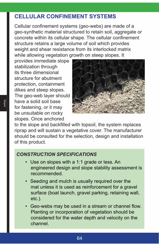
CELLULAR CONFINEMENT SYSTEMSCellular confinement systems (geo-webs) are made of a geo-synthetic material structured to retain soil, aggregate or concrete within its cellular shape. The cellular confinement structure retains a large volume of soil which provides weight and shear resistance from its interlocked matrix while allowing vegetation growth on steep slopes. It provides immediate slope stabilization through its three dimensional structure for abutment protection, containment dikes and steep slopes. The geo-web layer should have a solid soil base for fastening, or it may be unsuitable on rocky slopes. Once anchored to the slope and backfilled with topsoil, the system replaces riprap and will sustain a vegetative cover. The manufacturer should be consulted for the selection, design and installation of this product.
CONSTRUCTION SPECIFICATIONS• Use on slopes with a 1:1 grade or less. An
engineered design and slope stability assessment is recommended.
• Seeding and mulch is usually required over the mat unless it is used as reinforcement for a gravel surface (boat launch, gravel parking, retaining wall, etc.).
• Geo-webs may be used in a stream or channel flow. Planting or incorporation of vegetation should be considered for the water depth and velocity on the channel.

Slo
pes
65
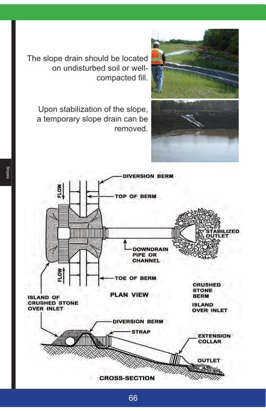
SLOPE DRAINSA slope drain is a stabilized conduit or channel that contains runoff down the face of a slope and to a stable discharge point. When used in conjunction with a diversion dike, a slope drain can redirect stormwater and prevent rill and gully erosion over an embankment. It can be a temporary or a permanent structure.
CONSTRUCTION SPECIFICATIONS• As a temporary measure, the slope drain
may consist of a heavy-duty flexible pipe or a constructed channel lined with plastic. A pipe should be at least 12 inches if used for more than one day. A permanent structure should be either revegetated or riprapped.
• A water diversion should direct the runoff to the drain at the top of the slope; and at the outlet of the diversion, a plunge pool or a level spreader are needed for a stable discharge.
• All connections should be secured to the slope (anchored or bermed) and watertight.
The slope drain structure should be inspected daily and during every storm event. The structure should be kept clear of sediment and debris.
Slopes
66
The slope drain should be located on undisturbed soil or well-
compacted fill.
Upon stabilization of the slope, a temporary slope drain can be
removed.
Sw
ales
an
d D
itche
s
67
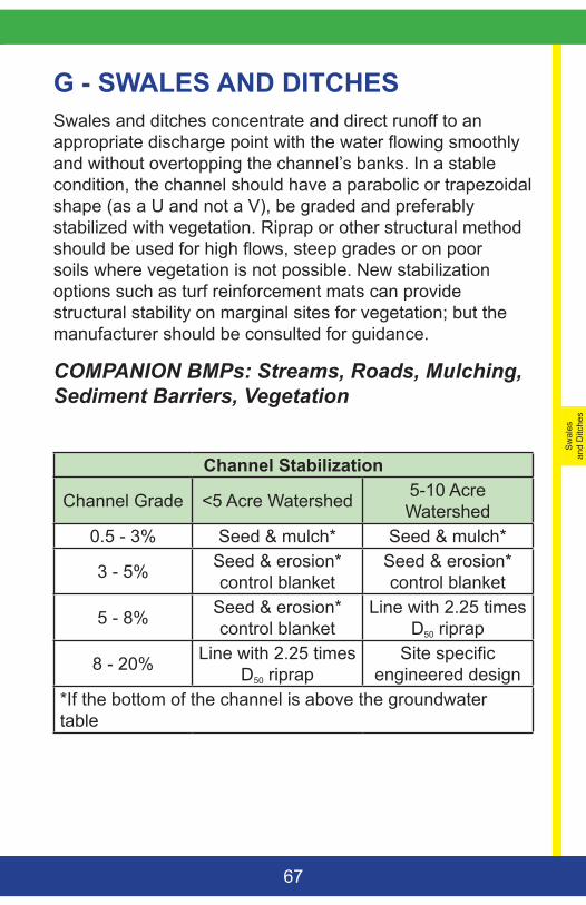
G - SWALES AND DITCHESSwales and ditches concentrate and direct runoff to an appropriate discharge point with the water flowing smoothly and without overtopping the channel’s banks. In a stable condition, the channel should have a parabolic or trapezoidal shape (as a U and not a V), be graded and preferably stabilized with vegetation. Riprap or other structural method should be used for high flows, steep grades or on poor soils where vegetation is not possible. New stabilization options such as turf reinforcement mats can provide structural stability on marginal sites for vegetation; but the manufacturer should be consulted for guidance.
COMPANION BMPs: Streams, Roads, Mulching, Sediment Barriers, Vegetation
Channel Stabilization
Channel Grade <5 Acre Watershed 5-10 Acre Watershed
0.5 - 3% Seed & mulch* Seed & mulch*
3 - 5% Seed & erosion* control blanket
Seed & erosion* control blanket
5 - 8% Seed & erosion* control blanket
Line with 2.25 times D50 riprap
8 - 20% Line with 2.25 times D50 riprap
Site specific engineered design
*If the bottom of the channel is above the groundwater table
Sw
ales and D
itches
68
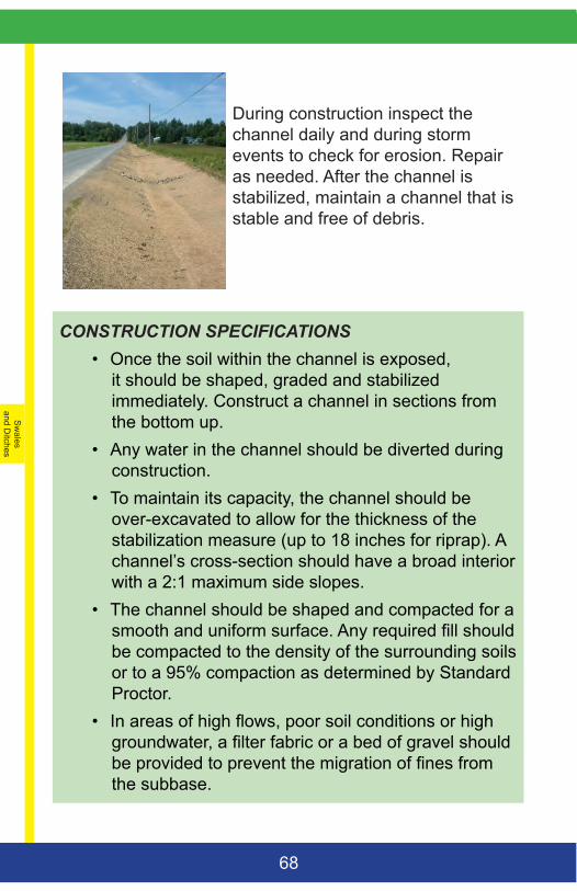
During construction inspect the channel daily and during storm events to check for erosion. Repair as needed. After the channel is stabilized, maintain a channel that is stable and free of debris.
CONSTRUCTION SPECIFICATIONS• Once the soil within the channel is exposed,
it should be shaped, graded and stabilized immediately. Construct a channel in sections from the bottom up.
• Any water in the channel should be diverted during construction.
• To maintain its capacity, the channel should be over-excavated to allow for the thickness of the stabilization measure (up to 18 inches for riprap). A channel’s cross-section should have a broad interior with a 2:1 maximum side slopes.
• The channel should be shaped and compacted for a smooth and uniform surface. Any required fill should be compacted to the density of the surrounding soils or to a 95% compaction as determined by Standard Proctor.
• In areas of high flows, poor soil conditions or high groundwater, a filter fabric or a bed of gravel should be provided to prevent the migration of fines from the subbase.
Sw
ales
an
d D
itche
s
69
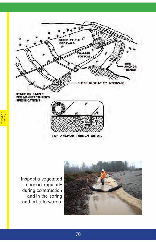
VEGETATED CHANNELS A vegetated waterway (roadside ditch, drainage swale, etc.) should be shaped or graded with a parabolic or trapezoidal cross-section and stabilized with healthy vegetation to prevent down cutting and channel migration.
CONSTRUCTION SPECIFICATIONS• Unless structural support is needed, mix loam into
the swale bottom and sides. • Upon final grading, the disturbed areas should be
seeded and mulched. Hay mulch is not appropriate in steep channels (greater than 5 % grade) with high flows or a strip of erosion control blanket at the base of the swale can protect the structure until vegetation is established. Follow the manufacturer’s specifications for stapling.
• The bottom of a vegetated ditch with continuous flow, a high water table, or seepage problems can be protected with stones (2-3 inches thick) or other reinforcement.
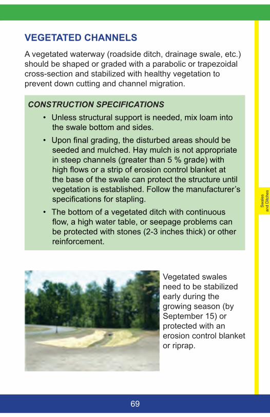
Vegetated swales need to be stabilized early during the growing season (by September 15) or protected with an erosion control blanket or riprap.
Sw
ales and D
itches
70
Inspect a vegetated channel regularly
during construction and in the spring
and fall afterwards.
Sw
ales
an
d D
itche
s
71
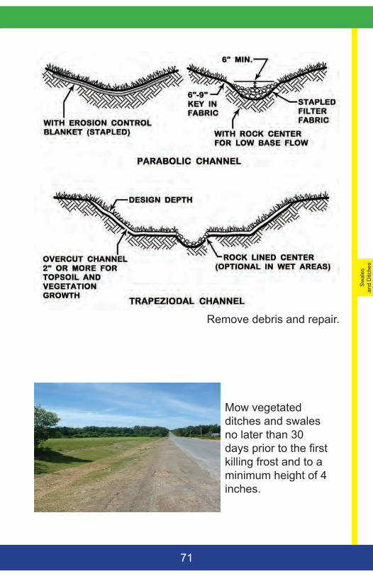
Remove debris and repair.
Mow vegetated ditches and swales no later than 30 days prior to the first killing frost and to a minimum height of 4 inches.
Sw
ales and D
itches
72
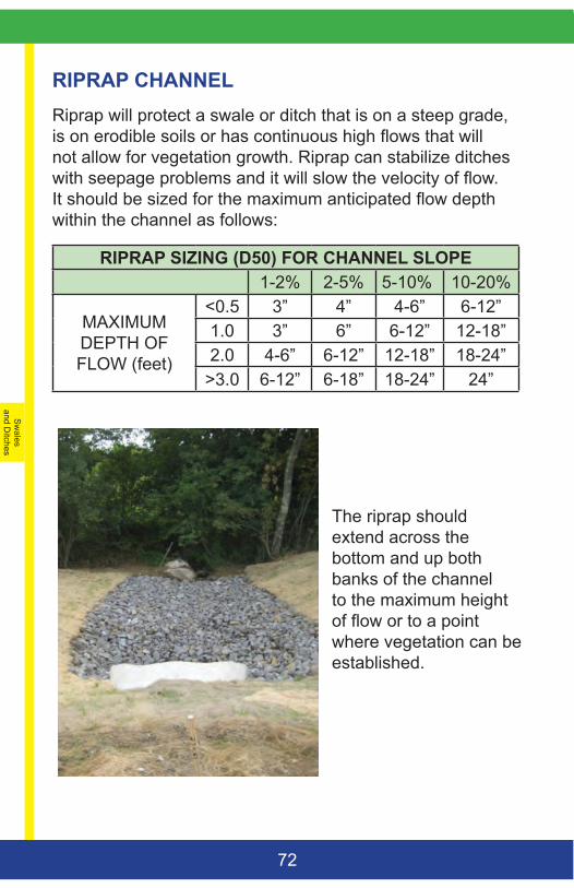
RIPRAP CHANNEL Riprap will protect a swale or ditch that is on a steep grade, is on erodible soils or has continuous high flows that will not allow for vegetation growth. Riprap can stabilize ditches with seepage problems and it will slow the velocity of flow. It should be sized for the maximum anticipated flow depth within the channel as follows:
RIPRAP SIZING (D50) FOR CHANNEL SLOPE1-2% 2-5% 5-10% 10-20%
MAXIMUM DEPTH OF FLOW (feet)
<0.5 3” 4” 4-6” 6-12”1.0 3” 6” 6-12” 12-18”2.0 4-6” 6-12” 12-18” 18-24”
>3.0 6-12” 6-18” 18-24” 24”
The riprap should extend across the bottom and up both banks of the channel to the maximum height of flow or to a point where vegetation can be established.
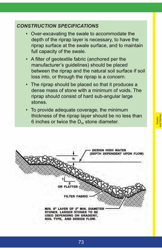
Sw
ales
an
d D
itche
s
73
CONSTRUCTION SPECIFICATIONS• Over-excavating the swale to accommodate the
depth of the riprap layer is necessary, to have the riprap surface at the swale surface, and to maintain full capacity of the swale.
• A filter of geotextile fabric (anchored per the manufacturer’s guidelines) should be placed between the riprap and the natural soil surface if soil loss into, or through the riprap is a concern.
• The riprap should be placed so that it produces a dense mass of stone with a minimum of voids. The riprap should consist of hard sub-angular large stones.
• To provide adequate coverage, the minimum thickness of the riprap layer should be no less than 6 inches or twice the D50 stone diameter.
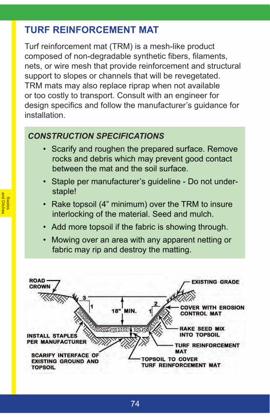
Sw
ales and D
itches
74
TURF REINFORCEMENT MAT Turf reinforcement mat (TRM) is a mesh-like product composed of non-degradable synthetic fibers, filaments, nets, or wire mesh that provide reinforcement and structural support to slopes or channels that will be revegetated. TRM mats may also replace riprap when not available or too costly to transport. Consult with an engineer for design specifics and follow the manufacturer’s guidance for installation.
CONSTRUCTION SPECIFICATIONS• Scarify and roughen the prepared surface. Remove
rocks and debris which may prevent good contact between the mat and the soil surface.
• Staple per manufacturer’s guideline - Do not under-staple!
• Rake topsoil (4” minimum) over the TRM to insure interlocking of the material. Seed and mulch.
• Add more topsoil if the fabric is showing through. • Mowing over an area with any apparent netting or
fabric may rip and destroy the matting.
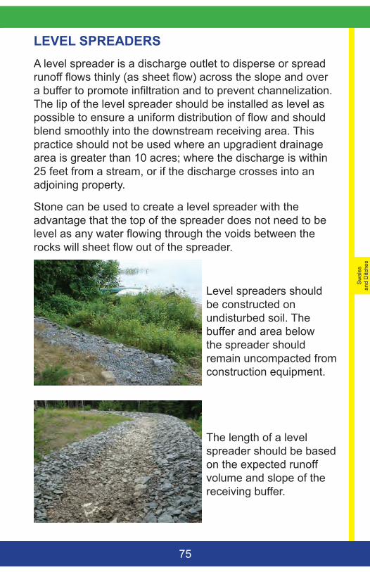
Sw
ales
an
d D
itche
s
75
LEVEL SPREADERS A level spreader is a discharge outlet to disperse or spread runoff flows thinly (as sheet flow) across the slope and over a buffer to promote infiltration and to prevent channelization. The lip of the level spreader should be installed as level as possible to ensure a uniform distribution of flow and should blend smoothly into the downstream receiving area. This practice should not be used where an upgradient drainage area is greater than 10 acres; where the discharge is within 25 feet from a stream, or if the discharge crosses into an adjoining property.
Stone can be used to create a level spreader with the advantage that the top of the spreader does not need to be level as any water flowing through the voids between the rocks will sheet flow out of the spreader.
Level spreaders should be constructed on undisturbed soil. The buffer and area below the spreader should remain uncompacted from construction equipment.
The length of a level spreader should be based on the expected runoff volume and slope of the receiving buffer.
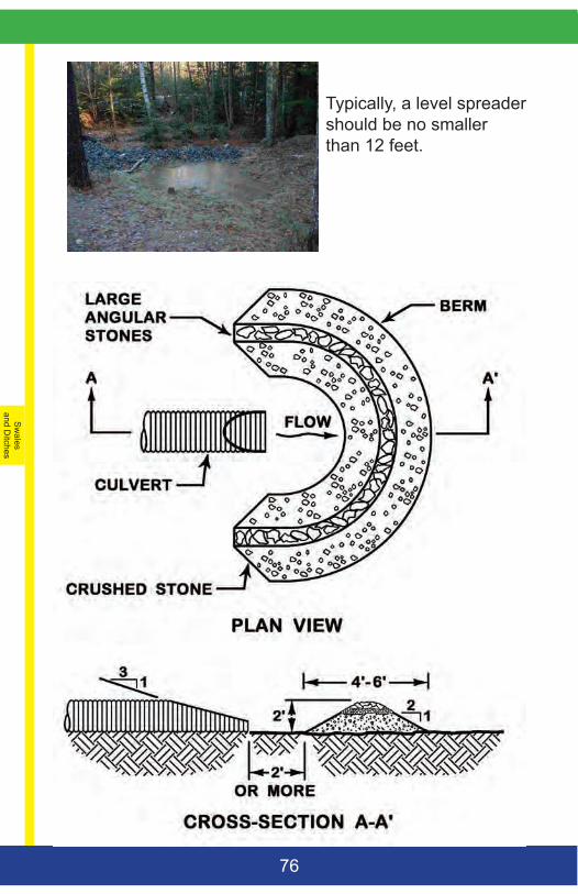
Sw
ales and D
itches
76
Typically, a level spreader should be no smaller than 12 feet.
Sw
ales
an
d D
itche
s
77
CONSTRUCTION SPECIFICATIONS• When discharging to a forested buffer, the receiving
area should remain undisturbed, have a duff layer, and have an uneven topography but without channelization that could concentrate runoff. A spreader should be located away from a stream or wetland.
• If revegetation of the receiving area is necessary, construction should be limited to the growing season (before September 1st). No water should be directed to the spreader before vegetation has reached 95% coverage and a temporary stormwater diversion may be needed.
• The lip of the level spreader should be installed on the contour to ensure a uniform distribution of flows or should consist of crushed rock (1”-3” are recommended) placed on the undisturbed part of the level lip to promote sheet flow and reduce velocity.
• The entry angle from the channel to the level spreader should be no greater than 30 degrees to prevent scour and short circuiting.
• Construction of a spreader should occur from the uphill side.
Cross
Culverts
78
H - CROSS-CULVERTSA culvert for a road crossing should be sized and installed correctly to prevent erosion or flooding. This guidance is only intended for the installation and stabilization of small culverts (driveways and small road crossings), and someone with expertise should be consulted for the crossing of a stream or for a pipe larger than 36 inches. The installation of any pipe (plastic, concrete, aluminum, steel, etc.) should also meet the requirements specified by the manufacturer.
COMPANION BMPs: Materials, Swales and Ditches, Streams, Roads, Mulching, Sediment Barriers, and Rock Sandwiches
NEWCULVERTS: Many variables affect a new cross-culvert (size of drainage area, depth and width of channel, soil types, elevation of road, length of culvert, etc.) and will need consideration. Unless the channel is well established and the size, slope, alignment and embedment of the culvert straight forward, consulting with a professional is recommended.
REPLACEMENTCULVERTS: A culvert to be replaced should be assessed for its current performance and capacity before considering a new pipe. Proper field determinations and measurements are necessary to ensure stability and capacity (i.e. watershed size, channel width and cross-section, alignment, length of pipe, elevation and width of the road, downgradient structures that depend upon detention, channel restrictions, etc.).
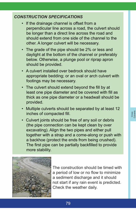
Cro
ss
Cul
verts
79
CONSTRUCTION SPECIFICATIONS• If the drainage channel is offset from a
perpendicular line across a road, the culvert should be longer than a direct line across the road and should extend from one side of the channel to the other. A longer culvert will be necessary.
• The grade of the pipe should be 2% or less and daylight at the bottom of the channel or preferably below. Otherwise, a plunge pool or riprap apron should be provided.
• A culvert installed over bedrock should have appropriate bedding; or an oval or arch culvert with footings may be necessary.
• The culvert should extend beyond the fill by at least one pipe diameter and be covered with fill as thick as one pipe diameter or a headwall should be provided.
• Multiple culverts should be separated by at least 12 inches of compacted fill.
• Culvert joints should be free of any soil or debris (the pipe connection can be kept clean by over excavating). Align the two pipes and either pull together with a strap and a come-along or push with a backhoe (protect the ends from being crushed). The first pipe can be partially backfilled to provide more stability.
The construction should be timed with a period of low or no flow to minimize a sediment discharge and it should not start if any rain event is predicted. Check the weather daily.
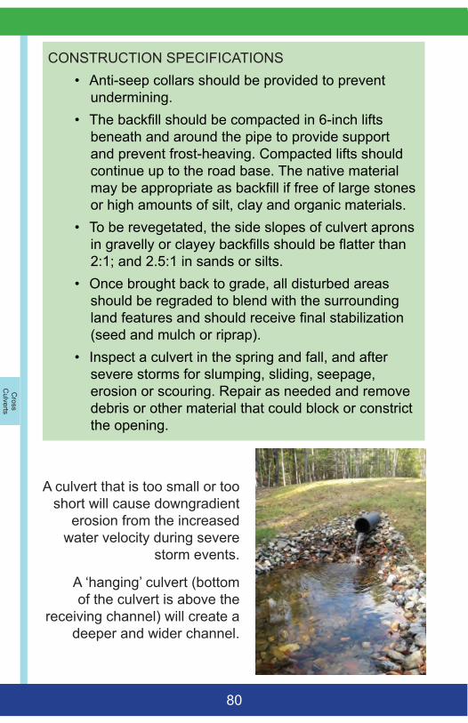
Cross
Culverts
80
CONSTRUCTION SPECIFICATIONS• Anti-seep collars should be provided to prevent
undermining.• The backfill should be compacted in 6-inch lifts
beneath and around the pipe to provide support and prevent frost-heaving. Compacted lifts should continue up to the road base. The native material may be appropriate as backfill if free of large stones or high amounts of silt, clay and organic materials.
• To be revegetated, the side slopes of culvert aprons in gravelly or clayey backfills should be flatter than 2:1; and 2.5:1 in sands or silts.
• Once brought back to grade, all disturbed areas should be regraded to blend with the surrounding land features and should receive final stabilization (seed and mulch or riprap).
• Inspect a culvert in the spring and fall, and after severe storms for slumping, sliding, seepage, erosion or scouring. Repair as needed and remove debris or other material that could block or constrict the opening.
A culvert that is too small or too short will cause downgradient
erosion from the increased water velocity during severe
storm events.
A ‘hanging’ culvert (bottom of the culvert is above the
receiving channel) will create a deeper and wider channel.
Cro
ss
Cul
verts
81
PIPE INLET PROTECTIONThe inlet is the gradual transition from ditch to pipe (small pool, catch basin, etc.) without overtopping or eroding the channel banks. The protection at the pipe inlet prevents scour and deterioration caused by flow velocity, change of direction, turbulence, or suction when water enters the pipe.
CONSTRUCTION SPECIFICATIONS• The inlet protection should extend at least one pipe
diameter above and beyond the conduit.• Inlet protection with vegetation may be appropriate
for small pipes that receive small flows and with an embankment that has a shallow side slope (3:1 or less). Seeding and mulching (hay or stapled erosion control blanket) should be applied within 7 days of final installation. Full stabilization is 95% vegetation.
• Riprap should be installed as soon as possible upon completion of a pipe inlet with a backslope steeper than 3:1. The rocks should be angular and sized to withstand the velocity of flow and should be underlain with a geotextile to prevent piping through the backfill material.
• The inlet protection should camber toward the swale’s side banks.
• Any other rigid retaining structures (headwall) should be reinforced to withstand settling, frost heaving, or any other loading without cracking or failing. Use industry standards for concrete structures.
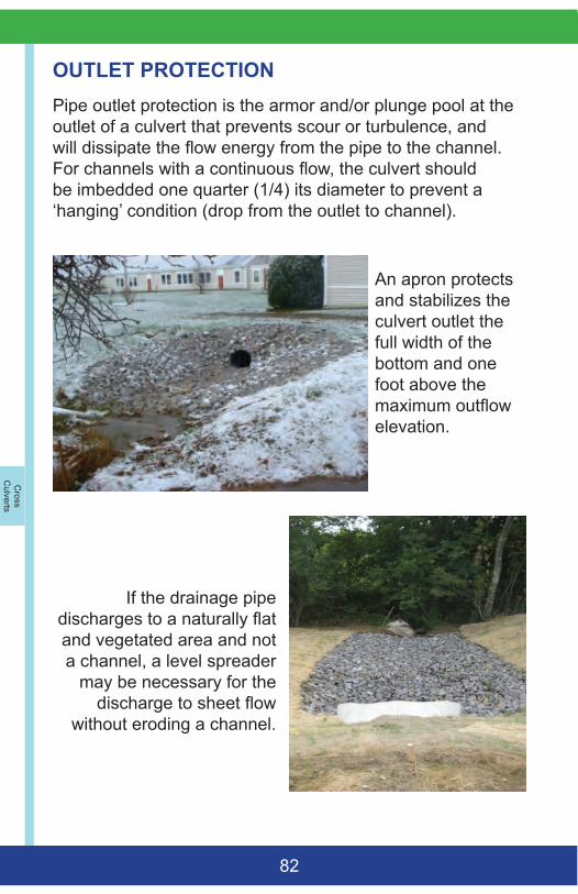
Cross
Culverts
82
OUTLET PROTECTION Pipe outlet protection is the armor and/or plunge pool at the outlet of a culvert that prevents scour or turbulence, and will dissipate the flow energy from the pipe to the channel. For channels with a continuous flow, the culvert should be imbedded one quarter (1/4) its diameter to prevent a ‘hanging’ condition (drop from the outlet to channel).
An apron protects and stabilizes the culvert outlet the full width of the bottom and one foot above the maximum outflow elevation.
If the drainage pipe discharges to a naturally flat and vegetated area and not a channel, a level spreader
may be necessary for the discharge to sheet flow
without eroding a channel.
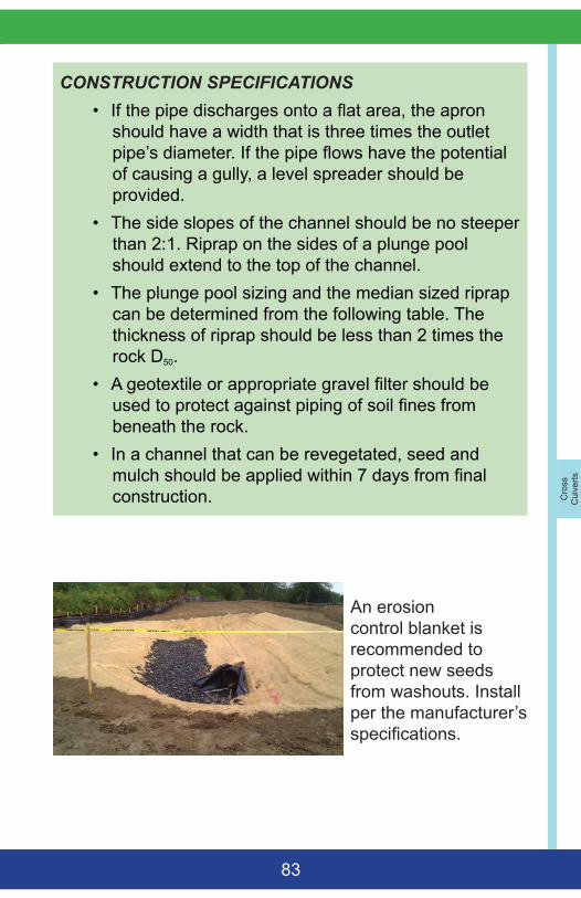
Cro
ss
Cul
verts
83
CONSTRUCTION SPECIFICATIONS• If the pipe discharges onto a flat area, the apron
should have a width that is three times the outlet pipe’s diameter. If the pipe flows have the potential of causing a gully, a level spreader should be provided.
• The side slopes of the channel should be no steeper than 2:1. Riprap on the sides of a plunge pool should extend to the top of the channel.
• The plunge pool sizing and the median sized riprap can be determined from the following table. The thickness of riprap should be less than 2 times the rock D50.
• A geotextile or appropriate gravel filter should be used to protect against piping of soil fines from beneath the rock.
• In a channel that can be revegetated, seed and mulch should be applied within 7 days from final construction.
An erosion control blanket is recommended to protect new seeds from washouts. Install per the manufacturer’s specifications.
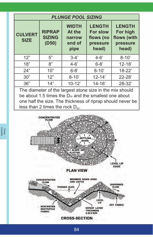
Cross
Culverts
84
PLUNGE POOL SIZING
CULVERT SIZE
RIPRAP SIZING (D50)
WIDTH At the narrow end of pipe
LENGTH For slow flows (no pressure
head)
LENGTH For high
flows (with pressure
head)
12” 5” 3-4’ 4-6’ 8-10’18” 8” 4-6’ 6-8’ 12-18’24” 10” 6-8’ 8-10’ 18-22’30” 12” 8-10’ 12-14’ 22-28’36” 14” 10-12’ 14-16’ 28-32’
The diameter of the largest stone size in the mix should be about 1.5 times the D50 and the smallest one about one half the size. The thickness of riprap should never be less than 2 times the rock D50.
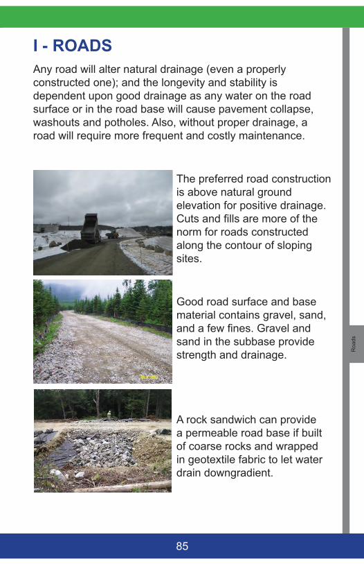
Roa
ds
85
I - ROADSAny road will alter natural drainage (even a properly constructed one); and the longevity and stability is dependent upon good drainage as any water on the road surface or in the road base will cause pavement collapse, washouts and potholes. Also, without proper drainage, a road will require more frequent and costly maintenance.
The preferred road construction is above natural ground elevation for positive drainage. Cuts and fills are more of the norm for roads constructed along the contour of sloping sites.
Good road surface and base material contains gravel, sand, and a few fines. Gravel and sand in the subbase provide strength and drainage.
A rock sandwich can provide a permeable road base if built of coarse rocks and wrapped in geotextile fabric to let water drain downgradient.
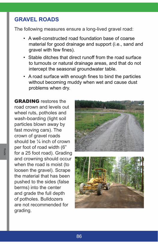
Roads
86
GRAVEL ROADS The following measures ensure a long-lived gravel road:
• A well-constructed road foundation base of coarse material for good drainage and support (i.e., sand and gravel with few fines).
• Stable ditches that direct runoff from the road surface to turnouts or natural drainage areas, and that do not intercept the seasonal groundwater table.
• A road surface with enough fines to bind the particles without becoming muddy when wet and cause dust problems when dry.
GRADING restores the road crown and levels out wheel ruts, potholes and wash-boarding (light soil particles blown away by fast moving cars). The crown of gravel roads should be ¼ inch of crown per foot of road width (6” for a 25 foot road). Grading and crowning should occur when the road is moist (to loosen the gravel). Scrape the material that has been pushed to the sides (false berms) into the center and grade the full depth of potholes. Bulldozers are not recommended for grading.
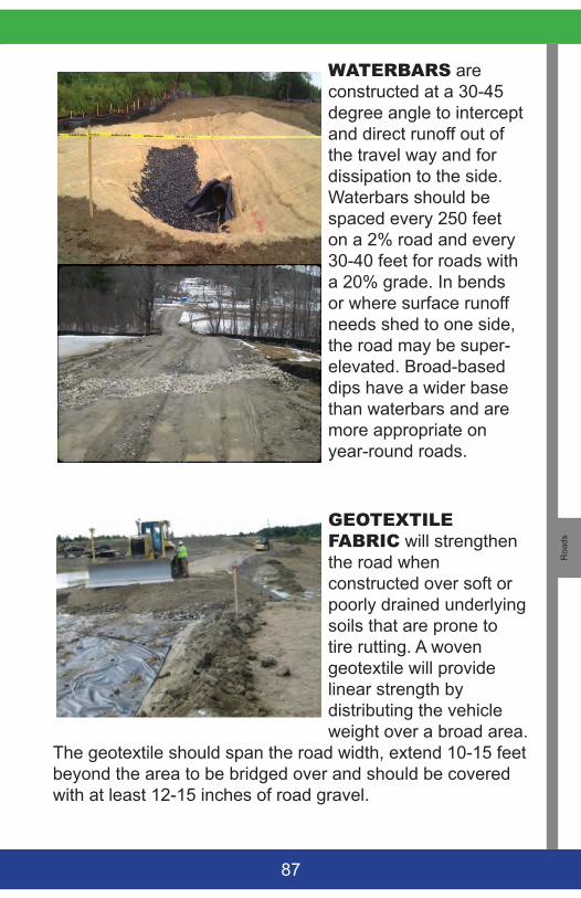
Roa
ds
87
WATERBARS are constructed at a 30-45 degree angle to intercept and direct runoff out of the travel way and for dissipation to the side. Waterbars should be spaced every 250 feet on a 2% road and every 30-40 feet for roads with a 20% grade. In bends or where surface runoff needs shed to one side, the road may be super-elevated. Broad-based dips have a wider base than waterbars and are more appropriate on year-round roads.
GEOTEXTILEFABRIC will strengthen the road when constructed over soft or poorly drained underlying soils that are prone to tire rutting. A woven geotextile will provide linear strength by distributing the vehicle weight over a broad area.
The geotextile should span the road width, extend 10-15 feet beyond the area to be bridged over and should be covered with at least 12-15 inches of road gravel.
Roads
88
CONSTRUCTION SPECIFICATIONS• If possible, a road should be constructed with an 8%
gradient or less and with cross culverts for water relief. Steeper roads may need riprapped ditches.
• The road base layer should consist of no less than 18-inches of coarse gravel. Soft roads are generally indicative of too many fines in the base material, persistent elevated groundwater table or a base layer that is too thin to support the road.
• The surface layer should be about 4-6 inches thick. The surface material needs to pack well, be durable, and shed water.
• Loose surface material generally indicates a lack of fines. The surface should have gravel with a maximum particle size of 2 inches (for a smooth ride) and 7-12% fines (to pack well and shed water) - Washboarding on a gravel road is the results of too few fines and high speed traffic. Reclaimed (ground up) pavement is more resistant to erosion with the residual asphalt acting as a binder. Ground-up pavement should be compacted with a roller to make a 3-4 inch surface layer.
• Drainage from the road surface is controlled with crowning, super-elevation and road bends. However, side ditches need to be appropriately located and should outlet to a stable area. Use frequent cross-culverts and/or ditches turnouts on long slopes.
• Stabilize all bare soils with seed and mulch or other protection.
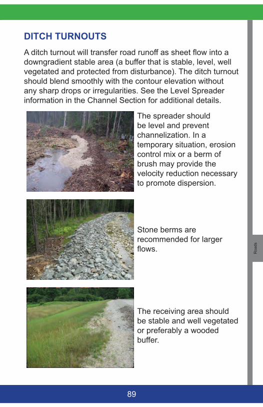
Roa
ds
89
DITCH TURNOUTSA ditch turnout will transfer road runoff as sheet flow into a downgradient stable area (a buffer that is stable, level, well vegetated and protected from disturbance). The ditch turnout should blend smoothly with the contour elevation without any sharp drops or irregularities. See the Level Spreader information in the Channel Section for additional details.
The spreader should be level and prevent channelization. In a temporary situation, erosion control mix or a berm of brush may provide the velocity reduction necessary to promote dispersion.
Stone berms are recommended for larger flows.
The receiving area should be stable and well vegetated or preferably a wooded buffer.
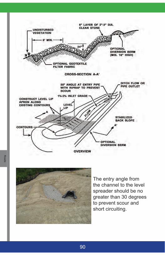
Roads
90
The entry angle from the channel to the level spreader should be no greater than 30 degrees to prevent scour and short circuiting.
Roa
ds
91
CONSTRUCTION SPECIFICATIONS• Each ditch turnout should discharge the runoff as
sheet flow. An easement may be necessary for flows that will cross into an adjoining property.
• Turnouts should be placed as far away from a stream as possible and on the contour.
• The spacing of ditch turnouts is a function of the road grade and volume of runoff. As a guide, one turnout should be provided every 200 feet for a road with a 2% grade and 30-40 feet for roads steeper than 10%.
• Ditch turnouts should be constructed in undisturbed soil. If fill is used, compaction of the fill should meet 95% of standard proctor.
• The dimensions (length and depth) of each ditch turnout depend upon the expected amount of runoff to allow pooling of the runoff before its discharge. The lip should be constructed along the contour and the side slopes should be less than 2:1 and stabilized.
• Once constructed, the turnout and level lip spreader may need to be stabilized with vegetation (seed and mulch – preferably erosion control blanket in the flow areas). or 4-6 inches of clean stone (not always necessary for level areas that are forested).
• Remove sediment from the ditch turnout when the swale is halfway full of sediment and debris or the structure is no longer functioning properly.
• Regularly inspect the ditch turnout for channelization or erosion and repair as soon as possible.
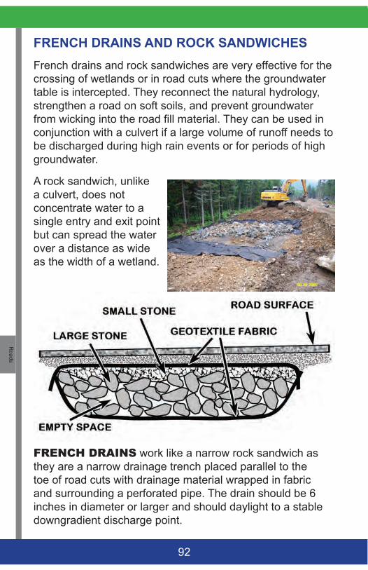
Roads
92
FRENCH DRAINS AND ROCK SANDWICHES French drains and rock sandwiches are very effective for the crossing of wetlands or in road cuts where the groundwater table is intercepted. They reconnect the natural hydrology, strengthen a road on soft soils, and prevent groundwater from wicking into the road fill material. They can be used in conjunction with a culvert if a large volume of runoff needs to be discharged during high rain events or for periods of high groundwater.
A rock sandwich, unlike a culvert, does not concentrate water to a single entry and exit point but can spread the water over a distance as wide as the width of a wetland.
FRENCHDRAINS work like a narrow rock sandwich as they are a narrow drainage trench placed parallel to the toe of road cuts with drainage material wrapped in fabric and surrounding a perforated pipe. The drain should be 6 inches in diameter or larger and should daylight to a stable downgradient discharge point.
Roa
ds
93
CONSTRUCTION SPECIFICATIONS• In a new wetland location, do not stump and grub
the surface under the road footprint. Cut trees close the ground, leaving the stumps and brush to provide structural support to the new road as it will not decompose under water. In a cut and fill location, minimize the area of ground disturbance and avoid excavating ditches!
• Place a woven geotextile fabric over the width of roadway with overlapping joints of at least 24”.
• The core material of the rock sandwich should be a layer that is 12” or more of clean 3-6” diameter stones placed on the full width of the roadway.
• Cover the rock layer with another filter fabric leaving the upgradient and downgradient ends of the rock layer exposed to allow the free movement of water.
• Place 6 inches or more of sub-base road fill, compact, and cover with surface material.
• When more than 2-3 feet of fill is needed to bring the road to finished grade, a third layer of filter fabric should be added for structural strength and to prevent the fines in the road subbase from moving to the drainage layer.
• Prevent plugging of the drainage layer by placing a layer of 3”-6” stone on the cut face up to the height of seeps to stabilize any seepage area.
• If the rock sandwich is in a crossing that has a defined drainage way that experience occasional large flows, a culvert should be installed slightly above the bottom of the rock sandwich for relief.
• Regularly check the upslope of the rock sandwich and clear any eroded soil, road sand, debris or leaf litter to prevent the clogging of the structure.
Stream
C
rossings
94
J - STREAM CROSSINGS Understanding the stream’s volume under all flow conditions, flow velocity; and of the soil in the area within or adjacent to a stream channel is necessary to minimize the risk of discharging sediments.
Any structure or work within the waterway of a stream is subject to the rules and regulations of the U.S. Army Corps of Engineers for in-stream modifications (404 permits), Land Use Planning Commission (LUPC) in unorganized territory and of the Maine DEP under the Natural Resources Protection Act. The Inland Fisheries and Wildlife Department should be consulted for fish spawning and passage issues. Other information and guidance may be available from the Maine Forest Service.
COMPANION BMPs: Vegetation, Riprap, Slopes, Roads, Cross Culverts
IMPORTANT NOTE:
Construction of Stream-Smart road crossings is recommended and begins with proper planning:
• Select the right place to cross a stream.• Determine the construction schedule, public use,
traffic, loads, and patterns of crossing. • Determine all necessary stream water controls
such as by-pass, pumping, cofferdams, etc. • Determine all stabilization measures and how the
stream will be restored to its natural conditions.• Identify an appropriate staging area for pipe
assembly, equipment and materials storage area, and for the disposal of construction debris.
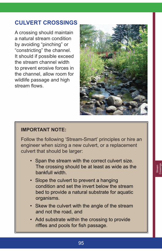
Stre
am
Cro
ssin
gs
95
CULVERT CROSSINGS A crossing should maintain a natural stream condition by avoiding “pinching” or “constricting” the channel. It should if possible exceed the stream channel width to prevent erosive forces in the channel, allow room for wildlife passage and high stream flows.
IMPORTANT NOTE:
Follow the following ‘Stream-Smart’ principles or hire an engineer when sizing a new culvert, or a replacement culvert that should be larger:
• Span the stream with the correct culvert size. The crossing should be at least as wide as the bankfull width.
• Slope the culvert to prevent a hanging condition and set the invert below the stream bed to provide a natural substrate for aquatic organisms.
• Skew the culvert with the angle of the stream and not the road, and
• Add substrate within the crossing to provide riffles and pools for fish passage.
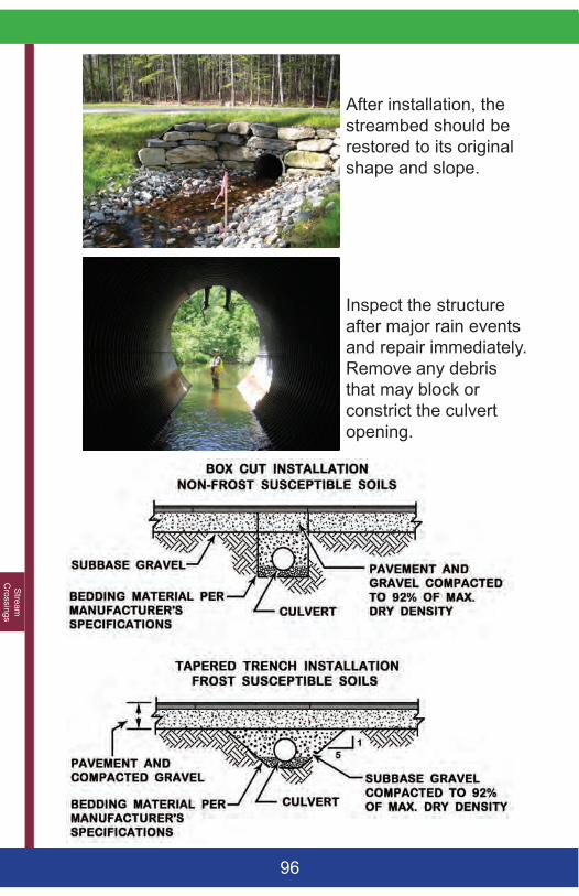
Stream
C
rossings
96
After installation, the streambed should be restored to its original shape and slope.
Inspect the structure after major rain events and repair immediately. Remove any debris that may block or constrict the culvert opening.
Stre
am
Cro
ssin
gs
97
CONSTRUCTION SPECIFICATIONS• Delay the construction if any major rain event is
predicted. Check the weather daily. • Locate the crossing where the crossing will minimize
soil disturbance and will receive the least amount of road runoff. Look for soils and embankments that will support equipment or that can be reinforced.
• Construction equipment should be kept out of streams.• The angle of the crossing should be within 15% from
the alignment of the stream. This will require a longer culvert.
• Roadside ditches should terminate to a level spreader and buffer if possible, and not at the stream.
• Culverts should be placed on compacted soil and stabilized with stone or gravel bedding material.
• Connect two lengths of culvert from downstream to upstream and protect the ends from crushing. The joints should be clean and free of soil or debris.
• Backfill should be installed in 6-inch lifts with compaction beneath and around the pipe to minimize frost heaves and washouts. Native material may be used if granular. Lift compaction should continue up to the subbase.
• Multiple culverts should be separated by at least 12 inches of compacted fill.
• Any riprap at the outlet or inlet needs be underlain by filter fabric. The rocks should be angular and durable.
• For vegetation, stapled erosion control blankets over seeding will be more effective than hay mulch.
• Rock sandwiches can be used in conjunction with a culvert to handle flood flows and maintain the floodplain characteristics.
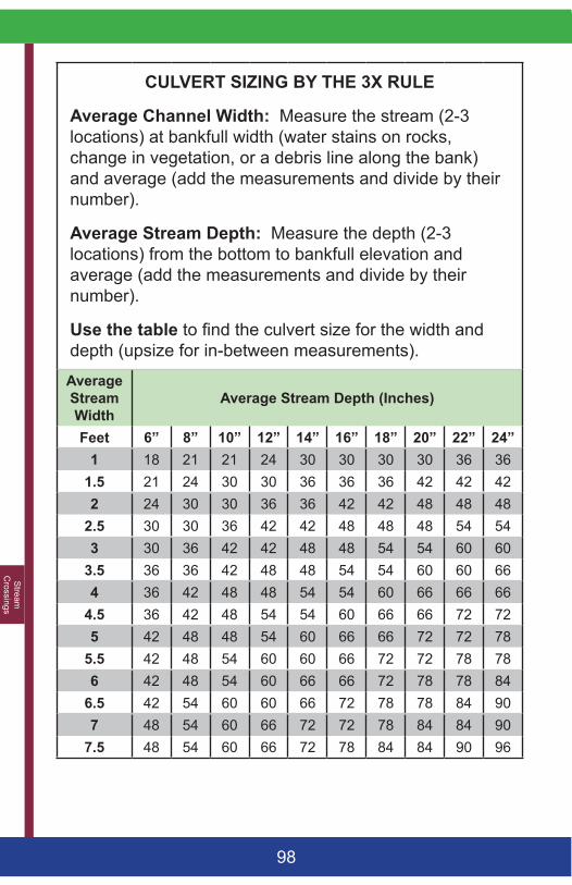
Stream
C
rossings
98
CULVERT SIZING BY THE 3X RULE
Average Channel Width: Measure the stream (2-3 locations) at bankfull width (water stains on rocks, change in vegetation, or a debris line along the bank) and average (add the measurements and divide by their number).
Average Stream Depth: Measure the depth (2-3 locations) from the bottom to bankfull elevation and average (add the measurements and divide by their number).
Use the table to find the culvert size for the width and depth (upsize for in-between measurements).
Average Stream Width
Average Stream Depth (Inches)
Feet 6” 8” 10” 12” 14” 16” 18” 20” 22” 24”1 18 21 21 24 30 30 30 30 36 36
1.5 21 24 30 30 36 36 36 42 42 422 24 30 30 36 36 42 42 48 48 48
2.5 30 30 36 42 42 48 48 48 54 543 30 36 42 42 48 48 54 54 60 60
3.5 36 36 42 48 48 54 54 60 60 664 36 42 48 48 54 54 60 66 66 66
4.5 36 42 48 54 54 60 66 66 72 725 42 48 48 54 60 66 66 72 72 78
5.5 42 48 54 60 60 66 72 72 78 786 42 48 54 60 66 66 72 78 78 84
6.5 42 54 60 60 66 72 78 78 84 907 48 54 60 66 72 72 78 84 84 90
7.5 48 54 60 66 72 78 84 84 90 96
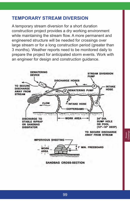
Stre
am
Cro
ssin
gs
99
TEMPORARY STREAM DIVERSIONA temporary stream diversion for a short duration construction project provides a dry working environment while maintaining the stream flow. A more permanent and engineered structure will be needed for crossings over large stream or for a long construction period (greater than 3 months). Weather reports need to be monitored daily to prepare the project for anticipated storm events. Work with an engineer for design and construction guidance.
Stream
C
rossings
100
CONSTRUCTION SPECIFICATIONS• The construction of a channel diversion should begin
from downstream and work upstream. • The diversion structure should be sized to contain
all stream flows. A large project would benefit from a cofferdam as well as a diversion.
• The conduit and pump should have the hydraulic capacity to handle all anticipated flows. The diversion should be constructed under dry conditions and be fully stabilized (sandbags or riprap) before use.
• Water from within the excavation/construction area should be pumped to a dewatering basin before reaching the stream.
• A block net should be provided upstream of the intake to reduce entrainment of fish and amphibians to a pump.
• A temporary by-pass pipe or culvert that is protected from crushing may be placed across the road.
• Clean water should re-enter the stream without scouring. A created apron of geotextile fabric and riprap or equivalent should be provided unless the discharge location is stable (rocky stream bed).
• The discharge hose(s) should be securely anchored.• A stream diversion should be regularly inspected
to ensure that the structure is not obstructed, that sediment is not discharging to the stream, or blocking fish passage. All damages should be repaired.
• If a major storm is predicted, emergency measures may be needed to prevent damage.
• At the end of construction, all temporary stream diversions should be removed and all areas stabilized and restored.
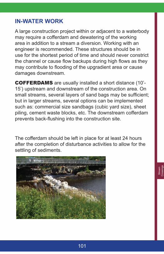
Stre
am
Cro
ssin
gs
101
IN-WATER WORK A large construction project within or adjacent to a waterbody may require a cofferdam and dewatering of the working area in addition to a stream a diversion. Working with an engineer is recommended. These structures should be in use for the shortest period of time and should never constrict the channel or cause flow backups during high flows as they may contribute to flooding of the upgradient area or cause damages downstream.
COFFERDAMS are usually installed a short distance (10’-15’) upstream and downstream of the construction area. On small streams, several layers of sand bags may be sufficient; but in larger streams, several options can be implemented such as: commercial size sandbags (cubic yard size), sheet piling, cement waste blocks, etc. The downstream cofferdam prevents back-flushing into the construction site.
The cofferdam should be left in place for at least 24 hours after the completion of disturbance activities to allow for the settling of sediments.
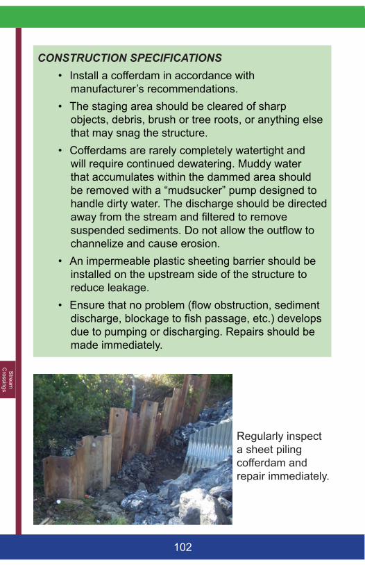
Stream
C
rossings
102
CONSTRUCTION SPECIFICATIONS• Install a cofferdam in accordance with
manufacturer’s recommendations.• The staging area should be cleared of sharp
objects, debris, brush or tree roots, or anything else that may snag the structure.
• Cofferdams are rarely completely watertight and will require continued dewatering. Muddy water that accumulates within the dammed area should be removed with a “mudsucker” pump designed to handle dirty water. The discharge should be directed away from the stream and filtered to remove suspended sediments. Do not allow the outflow to channelize and cause erosion.
• An impermeable plastic sheeting barrier should be installed on the upstream side of the structure to reduce leakage.
• Ensure that no problem (flow obstruction, sediment discharge, blockage to fish passage, etc.) develops due to pumping or discharging. Repairs should be made immediately.
Regularly inspect a sheet piling cofferdam and repair immediately.
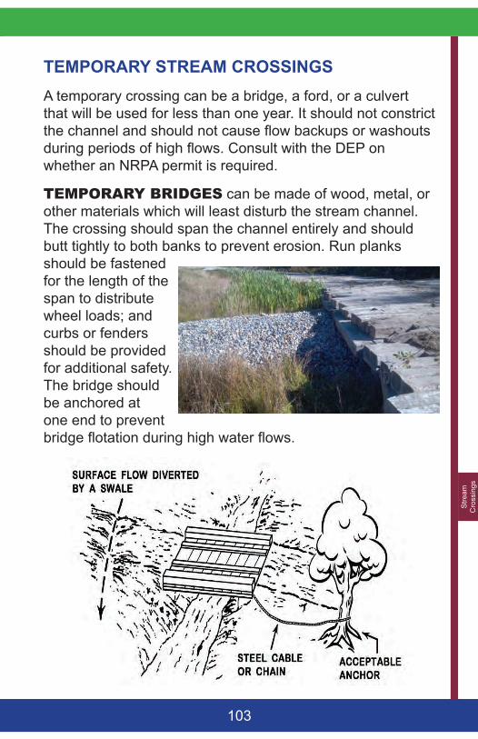
Stre
am
Cro
ssin
gs
103
TEMPORARY STREAM CROSSINGS A temporary crossing can be a bridge, a ford, or a culvert that will be used for less than one year. It should not constrict the channel and should not cause flow backups or washouts during periods of high flows. Consult with the DEP on whether an NRPA permit is required.
TEMPORARYBRIDGES can be made of wood, metal, or other materials which will least disturb the stream channel. The crossing should span the channel entirely and should butt tightly to both banks to prevent erosion. Run planks should be fastened for the length of the span to distribute wheel loads; and curbs or fenders should be provided for additional safety. The bridge should be anchored at one end to prevent bridge flotation during high water flows.
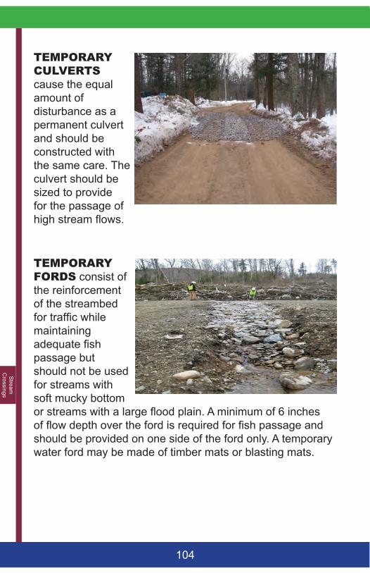
Stream
C
rossings
104
TEMPORARYCULVERTScause the equal amount of disturbance as a permanent culvert and should be constructed with the same care. The culvert should be sized to provide for the passage of high stream flows.
TEMPORARYFORDS consist of the reinforcement of the streambed for traffic while maintaining adequate fish passage but should not be used for streams with soft mucky bottom or streams with a large flood plain. A minimum of 6 inches of flow depth over the ford is required for fish passage and should be provided on one side of the ford only. A temporary water ford may be made of timber mats or blasting mats.
Stre
am
Cro
ssin
gs
105
CONSTRUCTION SPECIFICATIONS• A temporary stream crossing that will have to
overwinter should be sized for high flows. • Temporary crossings should be minimized (one lane
of traffic).• Locate the crossing for the least stream bed
disturbance and for bank stability (the narrower the stream and the stronger the banks are best). Site the structure where the stream banks have the strength to support vehicle access or reinforcement should be provided.
• The entire ford approach area should be protected with 4 -12 inches of coarse aggregate. Geotextile fabric (woven or nonwoven plastic) may be used to distribute the load, retain fines or reduce mixing of the aggregate with the stream bottom.
• Washed coarse aggregate (3/4” to 4”) is the preferred aggregate for fords. Sands, silts, or clays should not be used within the waterway.
• The crossing should not cause a hydraulic jump in the stream.
• A waterbar should divert road runoff to a level spreader and buffer within 50 feet from the crossing.
• Periodically inspect the crossing to ensure that debris or sediment are not discharging to the stream or blocking fish passage.
• The removal of excess materials from the waterway and re-stabilization of side banks is usually needed at the completion of the project. The road approaches through the banks should be permanently stabilized but not backfilled.
Appendix A
106
APPENDIX A: Erosion and Sediment Control Laws in Maine
Erosion and Sediment Control Law (M.R.S.A. 420-C)
The Erosion and Sedimentation Control Law (Erosion Control Law) applies to all construction projects in organized territories that will cause the filling, displacement or exposure of all earthen materials. The Erosion Control Law requires that appropriate measures be taken to prevent unreasonable soil erosion and sedimentation beyond the site or into a protected natural resource (such as a river, stream, brook, lake, pond, or wetland). Erosion control measures must be installed before construction activity, kept in place and maintained functional until the site is permanently stabilized.
Natural Resources Protection Act - NRPA (38 M.R.S.A. 480 A-Z)
NRPA regulates activities such as disturbing soil, placing fill, dredging, removing or displacing soil, sand or vegetation, draining or dewatering and building permanent structures in, on, over, and adjacent to lakes, ponds, river, streams, brooks, freshwater wetlands and tidal areas in organized territories. The DEP has authority to take enforcement actions such as: an after-the-fact permit, monetary penalties, consent agreements, or court action. The Land Use Planning Commission has permit granting authority under NRPA for regulated activities located in unorganized or de-organized areas of Maine.
App
endi
x A
107
Maine Construction General Permit (W008157-5Y-A-N)
Since March 10, 2003, construction activities in Maine require a Maine Construction General Permit (MCGP) as required by the EPA Clean Water Act. MCGP applies to construction activities in both organized and unorganized areas of Maine. Certain activities, such as forest management and farming, are exempt from the law; but a permit will be needed if the construction will result in one acre or more of disturbed area.
Shoreland Zoning (38 M.R.S.A. SECTION 438-A(4))
Shoreland Zoning Act (MSZA) requires municipalities to adopt, administer, and enforce local ordinances that regulate land use activities in the shoreland zone. The shoreland zone is comprised of all land areas within 250 feet (horizontal distance) of:
• The normal high-water line of any great pond or river;• The upland edge of a coastal wetland, including all
areas affected by tidal action, • The upland edge of defined freshwater wetlands; and• All land areas within 75 feet of the normal high-water
line of certain streams.
Stormwater Management Law (38 M.R.S.A. 420-D)
The law requires that a permit be obtained from the Department of Environmental Protection (DEP) for all projects that disturb more than one acre of land in organized territories of Maine. Proposed plans for stormwater management must be reviewed by the DEP before a new project is built.

Appendix A
108
Maine Land Use Planning Commission (12 M.R.S.A., § 681) and Development Review and Approval (12 M.R.S.A. § 685-B and §§ 685-B,1-A,B and B-1)
The Land Use Planning Commission (LUPC) of the Maine Department of Agriculture, Conservation and Forestry has the authority to regulate land use activities located in the unorganized and de-organized areas of Maine that require a permit, or are allowed without a permit subject to standards under LUPC’s Chapter 10 rules. http://www.maine.gov/dacf/lupc/laws_rules/ch10.html. Sections containing standards applicable to erosion control include, but are not limited to: Sections 10.25,K. Surface Water Quality, 10.25,M. Erosion and Sedimentation Control, 10.25,P. Wetland Alterations, 10.27,F. Filling and Grading, and Appendix B. Guidelines for Vegetative Stabilization. In the case of large scale developments triggering the DEP’s Site Law, DEP is the primary permitting authority and LUPC certifies to the DEP that any of its Chapter 10 standards not covered under Site Law have been met.
OTHER PERMITS
Many construction activities will require other local, state or federal permits prior to beginning construction. Contact your local, state and federal agencies to determine what regulations apply to your project:
• US Army Corps of Engineers for dredging, filling or building in or near wetlands and waterways.
• Department of Environmental Protection (DEP) for wetlands alteration.
• Code Enforcement Officer for the locality within which the project is proposed.
• Etc.

App
endi
x B
109
APP
END
IX B
: Mai
neD
OT
Stan
dard
Spe
cific
atio
ns MAT
ERIA
LS
717.
061
- Ero
sion
Con
trol B
lank
et
717.
04(d
) - E
rosi
on C
ontro
l Mix
722-
Geo
text
iles
703.
26 –
Pla
in a
nd H
and
Laid
R
ipra
p
703.
27 –
Pla
in a
nd H
and
Laid
R
ipra
p70
3.28
– H
eavy
Rip
rap
SPEC
IFIC
ATIO
NS
619
– M
ulch
613
– E
rosi
on C
ontro
l Bla
nket
s
615
– Lo
am61
6 - S
oddi
ng61
8 –
See
ding
621
- Lan
dsca
ping
(non
-gra
ss)
203
- Exc
avat
ion
and
Em
bank
men
t
620
- Geo
text
iles
610
- Sto
ne F
ill, R
ipra
p, S
tone
B
lank
et, a
nd S
tone
Ditc
h P
rote
ctio
n62
0 - G
eote
xtile
s
Mul
ch
Ero
sion
Con
trol M
ix B
erm
s an
d M
ulch
Vege
tatio
n
Slo
pes,
Cut
and
Fill
Geo
text
iles
Rip
rap
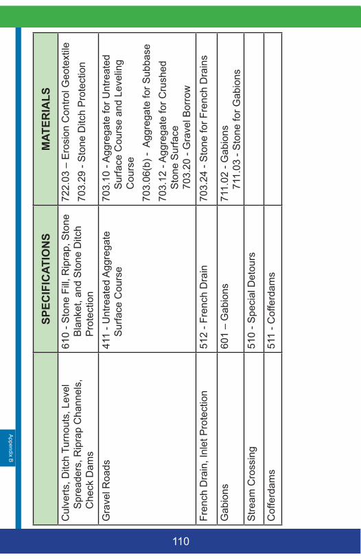
Appendix B
110
MAT
ERIA
LS
722.
03 –
Ero
sion
Con
trol G
eote
xtile
703.
29 -
Sto
ne D
itch
Pro
tect
ion
703.
10 -
Agg
rega
te fo
r Unt
reat
ed
Sur
face
Cou
rse
and
Leve
ling
Cou
rse
703.
06(b
) - A
ggre
gate
for S
ubba
se
703.
12 -
Agg
rega
te fo
r Cru
shed
S
tone
Sur
face
70
3.20
- G
rave
l Bor
row
703.
24 -
Sto
ne fo
r Fre
nch
Dra
ins
711.
02 -
Gab
ions
71
1.03
- S
tone
for G
abio
ns
SPEC
IFIC
ATIO
NS
610
- Sto
ne F
ill, R
ipra
p, S
tone
B
lank
et, a
nd S
tone
Ditc
h P
rote
ctio
n41
1 - U
ntre
ated
Agg
rega
te
Sur
face
Cou
rse
512
- Fre
nch
Dra
in
601
– G
abio
ns
510
- Spe
cial
Det
ours
511
- Cof
ferd
ams
Cul
verts
, Ditc
h Tu
rnou
ts, L
evel
S
prea
ders
, Rip
rap
Cha
nnel
s,
Che
ck D
ams
Gra
vel R
oads
Fren
ch D
rain
, Inl
et P
rote
ctio
n
Gab
ions
Stre
am C
ross
ing
Cof
ferd
ams

111

Maine Department of Environmental Protection 17 State House Station
28 Tyson Drive Augusta, Maine 04333 www.maine.gov/dep
March 2015