Embed Size (px)
Citation preview
Mainboard Series SL-85SD
User Manual v1.0
R
T h e S o u l O f C o m p u t e r T e c h n o l o g y
SL-85SDSL-85SD-XSL-85SDB
SL-85SD+
SL-85SD+-XSL-85SDB-X

his Users Guide & Technical Reference is to help system manu- facturers and end-users set up and install the mainboard.Every effort has been made to ensure that the information in thismanual is accurate. Soltek Computer Inc. is not responsible for print-ing or clerical errors. Information in this document is subject tochange without notice and does not represent a commitment onSoltek Computer Inc.No part of this manual may be reproduced, transmitted, translatedinto any language in any form or by any means, electronic ormechanical, including photocopying and recording, for any purposewithout the express written permission of Soltek Computer Inc.Companies and products mentioned in this manual are for identifi-cation purpose only. Product names appearing in this manual mayor may not be registered trademarks or copyrights of their respec-tive companies.
Soltek Computer Inc. provides this manual “As is “ without warrantyof any kind, either express or implied, including but not limited to theimplied warranties or conditions of merchantability or fitness for aparticular purpose. In no event shall Soltek Computer Inc. be liablefor any loss or profits, loss of business, loss of use or data, interruption ofbusiness, or for indirect, special, incidental, or consequential damages ofany kind, even if Soltek Computer Inc. has been advised of the possibilityof such damages arising from any defect or error in this manual or product.
Copyright © 2001 Soltek Computer Inc. All Rights Reserved.
NOTICEProduct Model : Series SL-85SDManual Revision : V1.0Release Date : August 2001
• Intel Pentium 4 and Northwood are trademarks of Intel Corporation.• Intel 845 is trademark of Intel Corporation.
mPGA478B
T

SOLTEK AROUND THE WORLD
SOLTEK COMPUTER INC.
Address : 7F, No. 306-3, Ta-Tung Rd, Sec.1, Hsi-Chih, Taipei-Hsien, Taiwan, R.O.C.
Telephone : 886-2-2642-9060
Fax : 886-2-2642-9065
E-mail : [email protected]
Web site : http://www.soltek.com.tw
SOUL TECHNOLOGY EUROPE B.V.
Address : Hongkongstraat 55, 3047 BP Rotterdam. The Neth-erlands
Telephone : 31-10-2457492
Fax : 31-10-2457493
E-mail : [email protected]
Web site : http://www.soultech-europe.com
Series SL-85SD
4
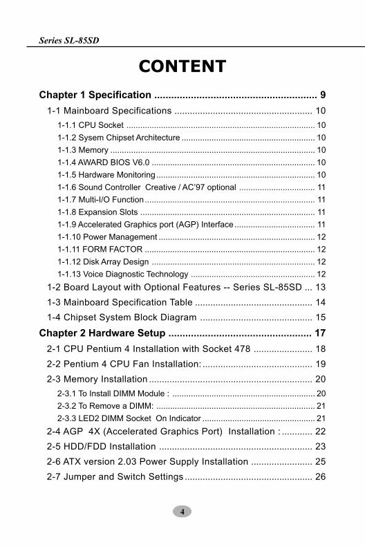
CONTENT
Chapter 1 Specification .......................................................... 9
1-1 Mainboard Specifications ...................................................... 10
1-1.1 CPU Socket .................................................................................. 10
1-1.2 Sysem Chipset Architecture .......................................................... 10
1-1.3 Memory ......................................................................................... 10
1-1.4 AWARD BIOS V6.0 ....................................................................... 10
1-1.5 Hardware Monitoring ..................................................................... 10
1-1.6 Sound Controller Creative / AC’97 optional ................................. 11
1-1.7 Multi-I/O Function.......................................................................... 11
1-1.8 Expansion Slots ............................................................................ 11
1-1.9 Accelerated Graphics port (AGP) Interface ................................... 11
1-1.10 Power Management .................................................................... 12
1-1.11 FORM FACTOR .......................................................................... 12
1-1.12 Disk Array Design ....................................................................... 12
1-1.13 Voice Diagnostic Technology ...................................................... 12
1-2 Board Layout with Optional Features -- Series SL-85SD ... 13
1-3 Mainboard Specification Table .............................................. 14
1-4 Chipset System Block Diagram ............................................ 15
Chapter 2 Hardware Setup ................................................... 17
2-1 CPU Pentium 4 Installation with Socket 478 ....................... 18
2-2 Pentium 4 CPU Fan Installation: ........................................... 19
2-3 Memory Installation ................................................................ 20
2-3.1 To Install DIMM Module : .............................................................. 20
2-3.2 To Remove a DIMM: ..................................................................... 21
2-3.3 LED2 DIMM Socket On Indicator ................................................. 21
2-4 AGP 4X (Accelerated Graphics Port) Installation : ............ 22
2-5 HDD/FDD Installation ............................................................ 23
2-6 ATX version 2.03 Power Supply Installation ........................ 25
2-7 Jumper and Switch Settings .................................................. 26
5
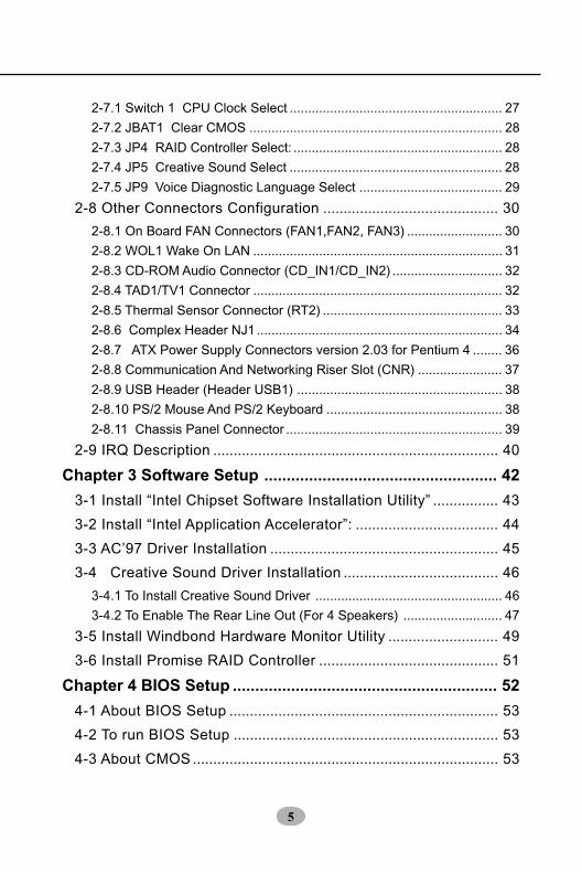
2-7.1 Switch 1 CPU Clock Select .......................................................... 27
2-7.2 JBAT1 Clear CMOS ..................................................................... 28
2-7.3 JP4 RAID Controller Select: ......................................................... 28
2-7.4 JP5 Creative Sound Select .......................................................... 28
2-7.5 JP9 Voice Diagnostic Language Select ....................................... 29
2-8 Other Connectors Configuration ........................................... 30
2-8.1 On Board FAN Connectors (FAN1,FAN2, FAN3) .......................... 30
2-8.2 WOL1 Wake On LAN .................................................................... 31
2-8.3 CD-ROM Audio Connector (CD_IN1/CD_IN2) .............................. 32
2-8.4 TAD1/TV1 Connector .................................................................... 32
2-8.5 Thermal Sensor Connector (RT2) ................................................. 33
2-8.6 Complex Header NJ1 ................................................................... 34
2-8.7 ATX Power Supply Connectors version 2.03 for Pentium 4 ........ 36
2-8.8 Communication And Networking Riser Slot (CNR) ....................... 37
2-8.9 USB Header (Header USB1) ........................................................ 38
2-8.10 PS/2 Mouse And PS/2 Keyboard ................................................ 38
2-8.11 Chassis Panel Connector ........................................................... 39
2-9 IRQ Description ...................................................................... 40
Chapter 3 Software Setup .................................................... 42
3-1 Install “Intel Chipset Software Installation Utility” ................ 43
3-2 Install “Intel Application Accelerator”: ................................... 44
3-3 AC’97 Driver Installation ........................................................ 45
3-4 Creative Sound Driver Installation ...................................... 46
3-4.1 To Install Creative Sound Driver ................................................... 46
3-4.2 To Enable The Rear Line Out (For 4 Speakers) ........................... 47
3-5 Install Windbond Hardware Monitor Utility ........................... 49
3-6 Install Promise RAID Controller ............................................ 51
Chapter 4 BIOS Setup ........................................................... 52
4-1 About BIOS Setup .................................................................. 53
4-2 To run BIOS Setup ................................................................. 53
4-3 About CMOS ........................................................................... 53
Series SL-85SD
6
4-4 The POST ( Power On Self Test ) ......................................... 53
4-5 To upgrade BIOS .................................................................... 54
4-5.1 Before Upgrading BIOS ................................................................ 54
4-5.2 Upgrade Process .......................................................................... 54
4-6 BIOS Setup --- CMOS Setup Utility ...................................... 57
4-6.1 CMOS Setup Utility ....................................................................... 57
4-6.2 Standard CMOS Setup ................................................................. 58
4-6.3 Advanced BIOS Features ............................................................. 61
4-6.4 Advanced Chipset Features .......................................................... 65
4-6.5 Integrated Peripherals ................................................................... 68
4-6.6 Power Management Setup ........................................................... 73
4-6.7 PNP / PCI Configuration ............................................................... 78
4-6.8 SmartDoc Anti-Burn Shield ........................................................... 81
4-6.9 Frequency/Voltage Control ........................................................... 83
4-6.10 Load Optimized Default .............................................................. 86
4-6.11 Set Supervisor / User Password ................................................. 87
4-6.12 Save & Exit Setup ....................................................................... 88
4-6.13 Exit Without Saving ..................................................................... 88
Chapter 5 RAID Controller ................................................... 90
5-0 Before Creating Dsik Array: ................................................. 91
5-1 Creating Your Disk Array ....................................................... 92
5-1.1 Creating An Array For Performance .............................................. 92
5-1.2 Creating A Security (Mirror) Array With New Drives ...................... 94
5-1.3 Creating Security Array With Existing Data Drive ......................... 96
5-2 Using FASTBUILDTM Configuration Utility .......................... 99
5-2.1 Viewing FastTrak100-Lite BIOS Screen ....................................... 99
5-2.2 Navigating the FastBuildTM Setup Menu ................................... 100
5-2.3 Using the Main Menu .................................................................. 100
5-2.4 Creating Arrays Automatically ..................................................... 101
5-2.5 Viewing Drive Assignments ......................................................... 103
5-2.6 View an Array .............................................................................. 103
5-2.7 Adding Fault Tolerance to an Existing Drive ............................... 104
5-2.8 Making a FastTrak100-Lite Disk Array Bootable ......................... 105
7
5-2.9 Creating a “Hot” Spare Drive for Mirroring Arrays ....................... 106
5-2.10 How FastTrak100-Lite Orders Arrays ....................................... 107
5-2.11 How FastTrak100-Lite Saves Array Information ........................ 107
5-2.12 Deleting An Array ...................................................................... 107
5-2.13 Rebuilding A Mirroring Array ..................................................... 109
5-2.14 Viewing Controller Settings ....................................................... 111
5-2.15 Halting FastTrak BIOS On Bootup Errors ................................. 111
5-3 Installing Drivers .................................................................. 112
5-3.1 For Windows 2000 ...................................................................... 112
5-3.2 Windows 95/98 ........................................................................... 114
5-3.3 DOS/Windows 3.1x ..................................................................... 117
5-3.4 Windows NT4.0 ........................................................................... 118
APPENDICES ....................................................................... 121
Appendix-1 Identify BIOS Version & BIOS Part Number ........ 122
Appendix-2 Identify Mainboard Model Number ....................... 124
Appendix-3 Technical Terms ...................................................... 125
Series SL-85SD
8
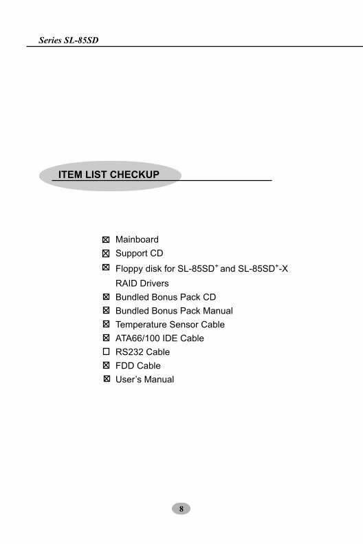
Mainboard
Support CD
Floppy disk for SL-85SD+ and SL-85SD+-X
RAID Drivers
Bundled Bonus Pack CD
Bundled Bonus Pack Manual
Temperature Sensor Cable
ATA66/100 IDE Cable
RS232 Cable
FDD Cable
User’s Manual
ITEM LIST CHECKUP
9
Chapter 1 Specification
Chapter 1 Specification
• This chapter introduces the characteristics of this series of mainboards. It in-cludes the information on the chipset, CPU types, built-in functions and layout.Users will have more ideas about this powerful series after reading this chapter.
The topics contained in this chapter are:
1-1 Mainboard Specifications
1-2 Mainboard Layout
1-3 Mainboard Specification Table
1-4 Chipset Diagram
Introduction
10
Series SL-85SD
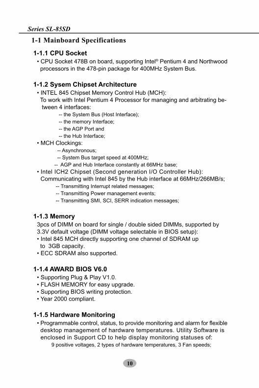
1-1.1 CPU Socket• CPU Socket 478B on board, supporting Intel® Pentium 4 and Northwood processors in the 478-pin package for 400MHz System Bus.
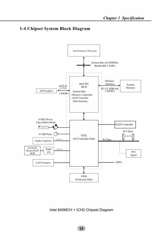
1-1.2 Sysem Chipset Architecture• INTEL 845 Chipset Memory Control Hub (MCH): To work with Intel Pentium 4 Processor for managing and arbitrating be- tween 4 interfaces: -- the System Bus (Host Interface); -- the memory Interface; -- the AGP Port and -- the Hub Interface;• MCH Clockings: -- Asynchronous; -- System Bus target speed at 400MHz; -- AGP and Hub Interface constantly at 66MHz base;• Intel ICH2 Chipset (Second generation I/O Controller Hub): Communicating with Intel 845 by the Hub interface at 66MHz/266MB/s; -- Transmitting Interrupt related messages; -- Transmitting Power management events; -- Transmitting SMI, SCI, SERR indication messages;
1-1.3 Memory3pcs of DIMM on board for single / double sided DIMMs, supported by3.3V default voltage (DIMM voltage selectable in BIOS setup):• Intel 845 MCH directly supporting one channel of SDRAM up to 3GB capacity.• ECC SDRAM also supported.
1-1.4 AWARD BIOS V6.0• Supporting Plug & Play V1.0.• FLASH MEMORY for easy upgrade.• Supporting BIOS writing protection.• Year 2000 compliant.
1-1.5 Hardware Monitoring• Programmable control, status, to provide monitoring and alarm for flexible desktop management of hardware temperatures. Utility Software is enclosed in Support CD to help display monitoring statuses of: 9 positive voltages, 2 types of hardware temperatures, 3 Fan speeds;
1-1 Mainboard Specifications
11
Chapter 1 Specification
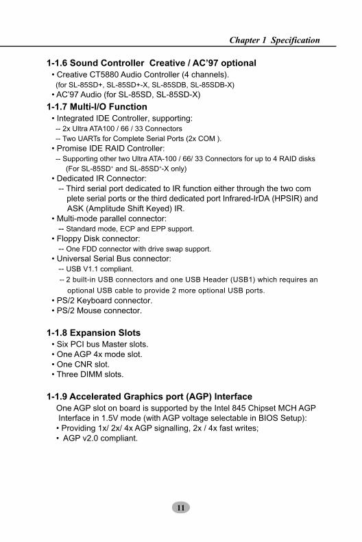
1-1.6 Sound Controller Creative / AC’97 optional• Creative CT5880 Audio Controller (4 channels). (for SL-85SD+, SL-85SD+-X, SL-85SDB, SL-85SDB-X)• AC’97 Audio (for SL-85SD, SL-85SD-X)
1-1.7 Multi-I/O Function• Integrated IDE Controller, supporting: -- 2x Ultra ATA100 / 66 / 33 Connectors -- Two UARTs for Complete Serial Ports (2x COM ).• Promise IDE RAID Controller: -- Supporting other two Ultra ATA-100 / 66/ 33 Connectors for up to 4 RAID disks (For SL-85SD+ and SL-85SD+-X only)• Dedicated IR Connector: -- Third serial port dedicated to IR function either through the two com plete serial ports or the third dedicated port Infrared-IrDA (HPSIR) and ASK (Amplitude Shift Keyed) IR.• Multi-mode parallel connector: -- Standard mode, ECP and EPP support.• Floppy Disk connector: -- One FDD connector with drive swap support.• Universal Serial Bus connector: -- USB V1.1 compliant.
-- 2 built-in USB connectors and one USB Header (USB1) which requires an
optional USB cable to provide 2 more optional USB ports.
• PS/2 Keyboard connector.• PS/2 Mouse connector.
1-1.8 Expansion Slots• Six PCI bus Master slots.• One AGP 4x mode slot.• One CNR slot.• Three DIMM slots.
1-1.9 Accelerated Graphics port (AGP) Interface One AGP slot on board is supported by the Intel 845 Chipset MCH AGP Interface in 1.5V mode (with AGP voltage selectable in BIOS Setup): • Providing 1x/ 2x/ 4x AGP signalling, 2x / 4x fast writes; • AGP v2.0 compliant.

12
Series SL-85SD
1-1.10 Power Management• ACPI 1.0B compliant (Advanced Configuration and Power Interface).• APM V1.2 compliant (Legacy power management).• Supporting ACPI suspend STR mode (Suspend To DRAM) and POS mode (Power On Suspend).• System event monitoring with two event classes.• Supporting PS/2 Keyboard & Mouse power on.• Supporting Wake On LAN (WOL) & Wake On Modem.• Supporting real time clock (RTC) with date alarm, month alarm, and century field.• USB wake-up Function.
1-1.11 FORM FACTOR• ATX form factor, ATX spec. version 2.03 compliant, with a Main Power Connector, a +12V Power Connector and an Aux Power Connector.• Mainboard size: 30.5cm x 24.5cm.
1-1.12 Disk Array DesignOn board SL-85SD+ and SL-85SD+-X• Promise FastTrak100-Lite RAID controller on board.• Supporting striping (RAID 0) and mirroring (RAID 1) Disk Arrays.• Supporting Ultra ATA/100 / 66 /33 specification up to 100MB/sec per drive.• Providing two RAID Connectors IDE3 and IDE4, Compatible with Ultra ATA/100/66/33 and EIDE.
1-1.13 Voice Diagnostic TechnologyOn board SL-85SD-X. SL-85SD+-X and SL-85SDB-X:• A Voice Diagnostic Function is incorporated in “Advanced BIOS Features” of the “Award BIOS Setup” as “VD-Tech II Function”. With this function enabled in “Advanced BIOS Features”, it will voice out the problems or conflicts whenever user configures the components or boots up the PC system.• The voice can be in Chinese or English, depending on the setting of Jumper JP10. Change the setting of JP10 will change the language of the voice.
13
Chapter 1 Specification
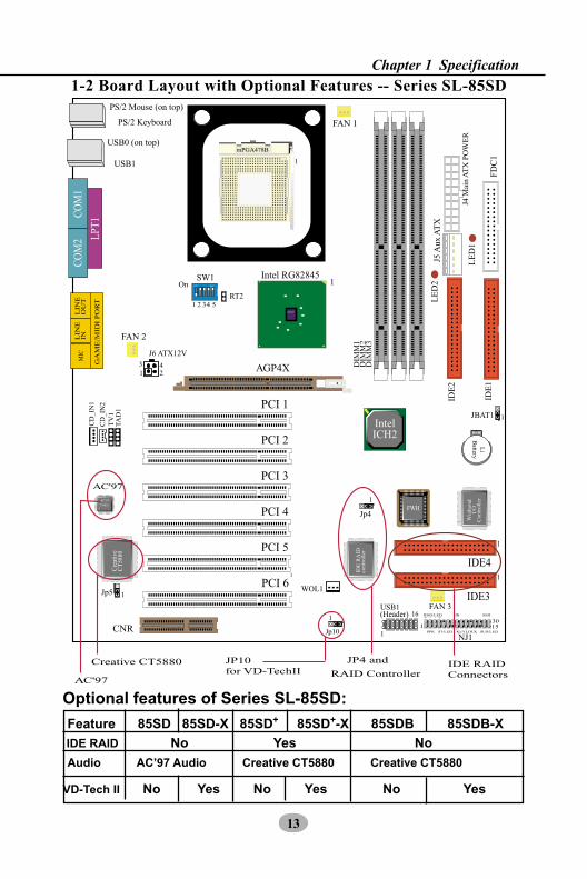
1-2 Board Layout with Optional Features -- Series SL-85SD
Optional features of Series SL-85SD:
Feature 85SD 85SD-X 85SD+ 85SD+-X 85SDB 85SDB-X
IDE RAID No Yes No
Audio AC’97 Audio Creative CT5880 Creative CT5880
VD-Tech II No Yes No Yes No Yes
Creative CT5880
AC'97
JP10�for VD-TechII
JP4 and
RAID ControllerIDE RAID�Connectors
PCI 1
PCI 2
PCI 3
PCI 4
PCI 5
PCI 6
CNR
Cre
ativ
e�C
T58
80
IDE
RA
ID�
cont
rolle
r
IDE4
IDE3
1
1
SPK S3/LED KEYLOCK SUS/LED
HDD/LED IR SMI+ +- -
+ -1
Li�
Battery
FWH
W
inbo
nd
�
I/O
�
Con
trol
ler
DIM
M1�
DIM
M2�
DIM
M3
USB1�(Header)�
1
16
GA
ME
/MID
I P
OR
T
LIN
E�
OU
TL
INE
�IN
LPT1
CO
M1
CO
M2
Intel�ICH2
1
1
1
1
ON DIP
SW1
WOL1
CD
_IN
1
CD
_IN
2
MIC
1
FAN 1
FAN 2
FAN 3
Jp10
Jp4
Jp5
TV
1TA
D1
J6 ATX12V
1 23 4
1
PS/2 Mouse (on top)
PS/2 Keyboard
USB0 (on top)
USB1 1
�
mPGA478B
2 34 5
Intel RG82845
Intel RG82845
AGP4X
RT2
1JBAT1
AC'97Codec
AC'97
On
�
NJ11530
IDE
1
IDE
2
FDC
1
J4 M
ain
AT
X P
OW
ER
J5 A
ux A
TX
LE
D2
LE
D1
14
Series SL-85SD
1-3 Mainboard Specification Table
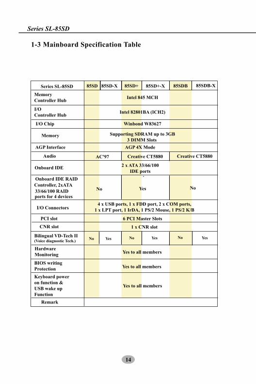
Series SL-85SD 85SD 85SD-X
MemoryController Hub
Intel 845 MCH
Intel 82801BA (ICH2)
Winbond W83627
I/OController Hub
I/O Chip
AGP Interface AGP 4X Mode
Memory Supporting SDRAM up to 3GB3 DIMM Slots
Audio
Onboard IDE
Onboard IDE RAID
2 x ATA 33/66/100IDE ports
I/O Connectors
Yes to all members
Yes to all members
Yes to all members
4 x USB ports, 1 x FDD port, 2 x COM ports,1 x LPT port, 1 IrDA, 1 PS/2 Mouse, 1 PS/2 K/B
PCI slot 6 PCI Master Slots
CNR slot 1 x CNR slot
HardwareMonitoring
Bilingual VD-Tech II(Voice diagnostic Tech.)
BIOS writingProtection
Keyboard poweron function &USB wake upFunction
Remark
85SD+ 85SD+-X 85SDB 85SDB-X
AC'97 Creative CT5880 Creative CT5880
No Yes No Yes No Yes
Controller, 2xATA33/66/100 RAID ports for 4 devices
No Yes No
15
Chapter 1 Specification
Intel 845MCH + ICH2 Chipset Diagram
1-4 Chipset System Block Diagram
SystemMemory
PCIAgent
SuperI/O
KeyboardMouse,FD,PP
SP,IR
PC133 SDRAM1.06GB/s
FWH(Firmware Hub)
ICH2(I/O Controller Hub)
Intel 845MCH
-Memory Controller-AGP Controller
PCI Bus
GPIO
System Bus (4x100MHz)Bandwidth 3.2GB/s
4 USB Ports
4 IDE Drives Ultra DMA100/66
PCI Slots
Audio Codec(s)
LAN Connect
Intel Pentium 4 Processor
AGP Graphics
AC'97 2.1
LPC I/F
Memory Interface
-System Bus
-Hub Interface
AGP 4x(1.5V)
1.06GB/s
RAID Controller

16
Series SL-85SD
MEMOMEMO
17
Chapter 2 Hardware Setup
Chapter 2 Hardware Setup
To Get things ready for Hardware setup !!!
1. We recommend to install your CPU before any othercomponentes. For detailed installalation instructionsof processor, you can also refer to the pamphlet en-closed in your CPU package.
2. Installing a cooling fan with a good heatsink is a mustfor proper heat dissipation for your CPU. Get readyan appropriate fan with heatsink for properinstallation. Inproper fan and installation will dam-age your CPU.
3. In case CPU Vcore, CPU clock or Frequency Ratio isadjustable on board, please follow the instructionsdescribed in the User manual for proper setup. In-correct setting will cause damage to your CPU.
The following topics are included in this chapter:
2-1 Pentium 4 CPU Installation
2-2 Pentium 4 CPU Fan Installation
2-3 Memory Installation
2-4 HDD/FDD Installation
2-5 AGP 4X (Accelerated Graphic Port) Installation
2-6 ATX 2.03 Power Supply Installation
2-7 Jumper Settings for Devices on board
2-8 Other Connectors Configuration
18
Series SL-85SD
mPG
A478B
Pin 1
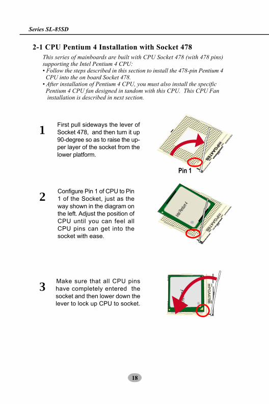
2-1 CPU Pentium 4 Installation with Socket 478This series of mainboards are built with CPU Socket 478 (with 478 pins)supporting the Intel Pentium 4 CPU:• Follow the steps described in this section to install the 478-pin Pentium 4 CPU into the on board Socket 478.• After installation of Pentium 4 CPU, you must also install the specific Pentium 4 CPU fan designed in tandom with this CPU. This CPU Fan installation is described in next section.
First pull sideways the lever ofSocket 478, and then turn it up90-degree so as to raise the up-per layer of the socket from thelower platform.
1
Make sure that all CPU pinshave completely entered thesocket and then lower down thelever to lock up CPU to socket.
3
Configure Pin 1 of CPU to Pin1 of the Socket, just as theway shown in the diagram onthe left. Adjust the position ofCPU until you can feel allCPU pins can get into thesocket with ease.
2
mPG
A478B
Intel Pe
ntium 4
mP
GA
478B
Intel Pe
ntium 4
19
Chapter 2 Hardware Setup
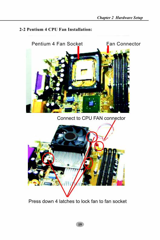
2-2 Pentium 4 CPU Fan Installation:
Connect to CPU FAN connector
Press down 4 latches to lock fan to fan socket
Pentium 4 Fan Socket Fan Connector
20
Series SL-85SD
2-3 Memory Installation
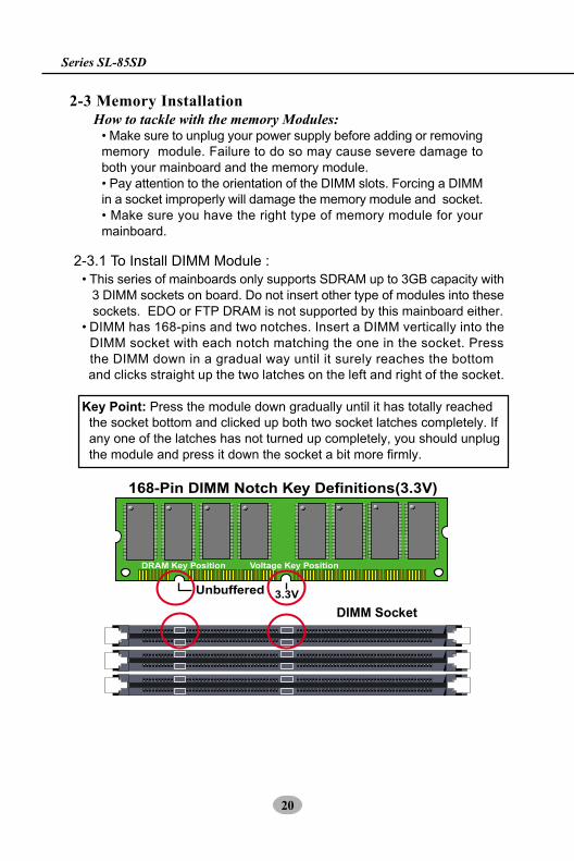
2-3.1 To Install DIMM Module :• This series of mainboards only supports SDRAM up to 3GB capacity with 3 DIMM sockets on board. Do not insert other type of modules into these sockets. EDO or FTP DRAM is not supported by this mainboard either.• DIMM has 168-pins and two notches. Insert a DIMM vertically into the DIMM socket with each notch matching the one in the socket. Press the DIMM down in a gradual way until it surely reaches the bottom and clicks straight up the two latches on the left and right of the socket.
Key Point: Press the module down gradually until it has totally reached the socket bottom and clicked up both two socket latches completely. If any one of the latches has not turned up completely, you should unplug the module and press it down the socket a bit more firmly.
How to tackle with the memory Modules:• Make sure to unplug your power supply before adding or removingmemory module. Failure to do so may cause severe damage toboth your mainboard and the memory module.• Pay attention to the orientation of the DIMM slots. Forcing a DIMMin a socket improperly will damage the memory module and socket.• Make sure you have the right type of memory module for yourmainboard.
168-Pin DIMM Notch Key Definitions(3.3V)
DRAM Key Position Voltage Key Position
Unbuffered 3.3V
DIMM Socket
21
Chapter 2 Hardware Setup
2-3.3 LED2 DIMM Socket On Indicator
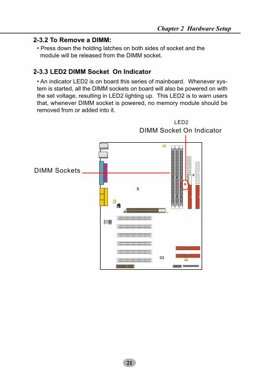
2-3.2 To Remove a DIMM:• Press down the holding latches on both sides of socket and the module will be released from the DIMM socket.
• An indicator LED2 is on board this series of mainboard. Whenever sys-tem is started, all the DIMM sockets on board will also be powered on withthe set voltage, resulting in LED2 lighting up. This LED2 is to warn usersthat, whenever DIMM socket is powered, no memory module should beremoved from or added into it.
1
LED2
DIMM Sockets
DIMM Socket On Indicator
22
Series SL-85SD
2-4 AGP 4X (Accelerated Graphics Port) Installation :
AGP Accelerator
AGP4X
4X notch
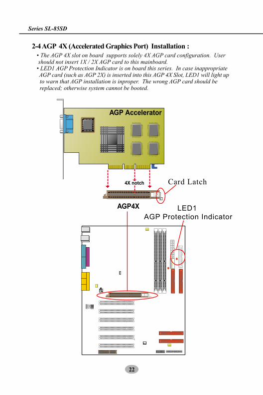
• The AGP 4X slot on board supports solely 4X AGP card configuration. User should not insert 1X / 2X AGP card to this mainboard.
Card Latch
1
AGP Protection IndicatorLED1
• LED1 AGP Protection Indicator is on board this series. In case inappropriate AGP card (such as AGP 2X) is inserted into this AGP 4X Slot, LED1 will light up to warn that AGP installation is inproper. The wrong AGP card should be replaced; otherwise system cannot be booted.
23
Chapter 2 Hardware Setup
1
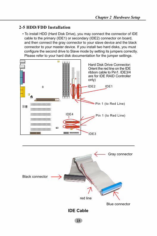
• To install HDD (Hard Disk Drive), you may connect the connector of IDE cable to the primary (IDE1) or secondary (IDE2) connector on board, and then connect the gray connector to your slave device and the black connector to your master device. If you install two hard disks, you must configure the second drive to Slave mode by setting its jumpers correctly. Please refer to your hard disk documentation for the jumper settings.
Hard Disk Drive Connector:Orient the red line on the IDEribbon cable to Pin1. IDE3/4are for IDE RAID Controlleronly)
2-5 HDD/FDD Installation
Gray connector
Blue connector
IDE Cable
Black connector
red line
IDE2 IDE1
IDE4
IDE3
Pin 1 (to Red Line)
Pin 1 (to Red Line)
24
Series SL-85SD
FDD Cable
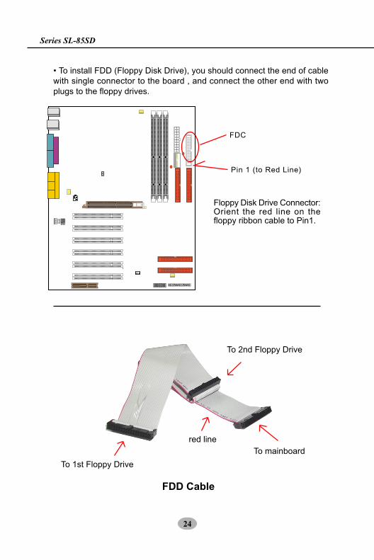
• To install FDD (Floppy Disk Drive), you should connect the end of cablewith single connector to the board , and connect the other end with twoplugs to the floppy drives.
To 1st Floppy Drive
To mainboard
To 2nd Floppy Drive
Floppy Disk Drive Connector:Orient the red line on thefloppy ribbon cable to Pin1.
red line
1
Pin 1 (to Red Line)
FDC
25
Chapter 2 Hardware Setup
1
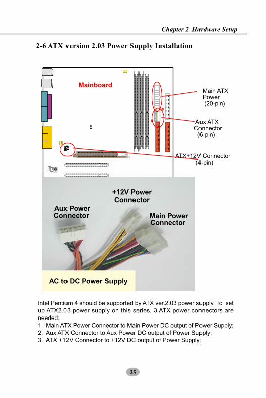
2-6 ATX version 2.03 Power Supply Installation
Aux ATX Connector (6-pin)
Main ATX Power (20-pin)
ATX+12V Connector (4-pin)
Mainboard
Intel Pentium 4 should be supported by ATX ver.2.03 power supply. To setup ATX2.03 power supply on this series, 3 ATX power connectors areneeded:1. Main ATX Power Connector to Main Power DC output of Power Supply;2. Aux ATX Connector to Aux Power DC output of Power Supply;3. ATX +12V Connector to +12V DC output of Power Supply;
AC to DC Power Supply
+12V Power
Main PowerConnector
Aux PowerConnector
Connector
26
Series SL-85SD
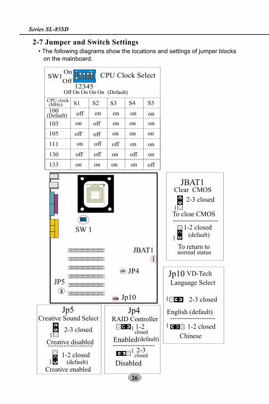
2-7 Jumper and Switch Settings• The following diagrams show the locations and settings of jumper blocks on the mainboard.
ON DIP
1
Jp5
1-2 closed
JBAT1
JP4
JP5
JBAT1Clear CMOS
12-3 closed
To clear CMOS--------------------
To return to
11-2 closed
Creative Sound Select
12-3 closed
Creative disabled--------------------
Creative enabled
SW 1
(default)
Jp10
1-2 closed
VD-Tech
1 2-3 closed
English (default)--------------------
Chinese
Language Select
1
Jp10
ON DIP
SW1On
Off12345
CPU Clock Select
�S1 S2 S3 S4 S5CPU clock
(MHz)100
103
105
111
130
133
off on on on on
on on on on
on on on
on on on
on on
on on on on
off
off off
off off
off off off
off
(Default)
Off On On On On (Default)
normal status
1
�mPGA478B
(default)
1
1
Jp4
2-3 closed
1-2closed
RAID Controller
Enabled
Disabled
-----------------(default)

27
Chapter 2 Hardware Setup
How to tackle with Jumpers:• Do not remove the jumper when power is on. Always make sure the power is off before changing any jumper settings. Otherwise, mainboard could be damaged.• In the Jumper setting diagram, all jumper pins covered with black marks stand for closed pins by jumper caps.
2-7.1 Switch 1 CPU Clock Select
• This Series of mainboards are shipped to users with a 5-DIP Switch 1,by which user can select a CPU clock to match with the Pentium 4 proces-sor selected on board. So users are not recommeded to take Switch 1 asa tool for overclocking. It is saver and more advisible for users to select theCPU clock as close as possible to the one marked on the selected CPU.
ON DIP
SW1On
Off12345
CPU Clock Select
�S1 S2 S3 S4 S5CPU clock
(MHz)100
103
105
111
130
133
off on on on on
on on on on
on on on
on on on
on on
on on on on
off
off off
off off
off off off
off
(Default)
Off On On On On (Default)
• Advice from our Engineering Team:
If you insert a Pentium 4 processor of 100MHz to the CPU socket andselect 103MHz or any higher Switch setting, you are taking the risk of break-ing the stability of your CPU as well as the mainboard. Overclocking shouldalways take all other components on board into account.
28
Series SL-85SD
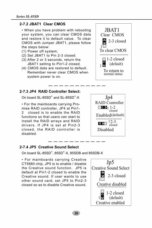
2-7.4 JP5 Creative Sound Select
2-7.2 JBAT1 Clear CMOS
Jp5
11-2 closed
Creative Sound Select
12-3 closed
Creative disabled--------------------
Creative enabled(default)
1
1-2 closed
JBAT1Clear CMOS
12-3 closed
To clear CMOS--------------------
To return to
(default)
normal status
• For mainboards carrying CreativeCT5880 chip, JP5 is to enable / disablethe Creative sound function. JP5 isdefault at Pin1-2 closed to enable theCreative sound. If user wants to useother sound card, set JP5 to Pin2-3closed so as to disable Creative sound.
• When you have problem with rebootingyour system, you can clear CMOS dataand restore it to default value. To clearCMOS with Jumper JBAT1, please followthe steps below:(1) Power off system;(2) Set JBAT1 to Pin 2-3 closed.(3) After 2 or 3 seconds, return the JBAT1 setting to Pin1-2 closed.(4) CMOS data are restored to default. Remember never clear CMOS when system power is on.
2-7.3 JP4 RAID Controller Select:
1
1
Jp4
2-3 closed
1-2closed
RAID Controller
Enabled
Disabled
-----------------(default)
• For the mainboards carrying Pro-mise RAID controller, JP4 at Pin1-2 closed is to enable the RAIDfunctions so that users can start toinstall the RAID arrays and RAIDdr ivers. I f JP4 is set at P in2-3c losed, the RAID cont ro l le r i sdisabled.
On board SL-85SD+ and SL-85SD+-X
On board SL-85SD+, 85SD+-X, 85SDB and 85SDB-X
29
Chapter 2 Hardware Setup
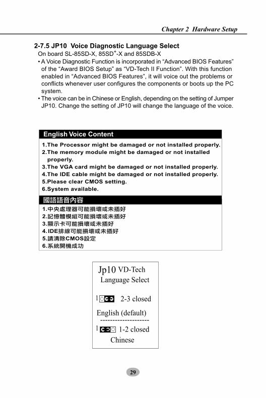
2-7.5 JP10 Voice Diagnostic Language SelectOn board SL-85SD-X, 85SD+-X and 85SDB-X• A Voice Diagnostic Function is incorporated in “Advanced BIOS Features” of the “Award BIOS Setup” as “VD-Tech II Function”. With this function enabled in “Advanced BIOS Features”, it will voice out the problems or conflicts whenever user configures the components or boots up the PC system.• The voice can be in Chinese or English, depending on the setting of Jumper JP10. Change the setting of JP10 will change the language of the voice.
1.The Processor might be damaged or not installed properly.2.The memory module might be damaged or not installed properly.3.The VGA card might be damaged or not installed properly.4.The IDE cable might be damaged or not installed properly.5.Please clear CMOS setting.6.System available.
Jp10
1-2 closed
VD-Tech
1 2-3 closed
English (default)--------------------
Chinese
Language Select
1
30
Series SL-85SD
1
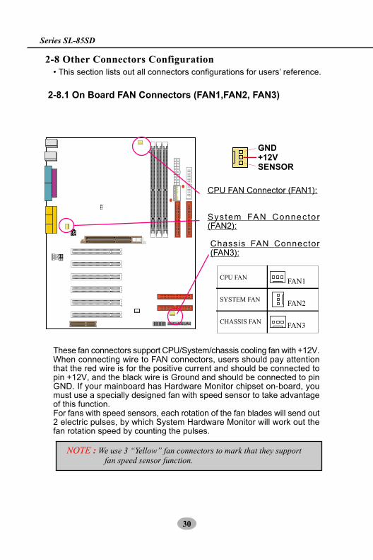
These fan connectors support CPU/System/chassis cooling fan with +12V.When connecting wire to FAN connectors, users should pay attentionthat the red wire is for the positive current and should be connected topin +12V, and the black wire is Ground and should be connected to pinGND. If your mainboard has Hardware Monitor chipset on-board, youmust use a specially designed fan with speed sensor to take advantageof this function.For fans with speed sensors, each rotation of the fan blades will send out2 electric pulses, by which System Hardware Monitor will work out thefan rotation speed by counting the pulses.
NOTE : We use 3 “Yellow” fan connectors to mark that they support fan speed sensor function.
CPU FAN Connector (FAN1):
2-8.1 On Board FAN Connectors (FAN1,FAN2, FAN3)
2-8 Other Connectors Configuration• This section lists out all connectors configurations for users’ reference.
Sys tem FAN Connec to r(FAN2):
Chassis FAN Connector(FAN3):
GND+12VSENSOR
FAN1
FAN2
FAN3
CPU FAN
SYSTEM FAN
CHASSIS FAN
31
Chapter 2 Hardware Setup
1
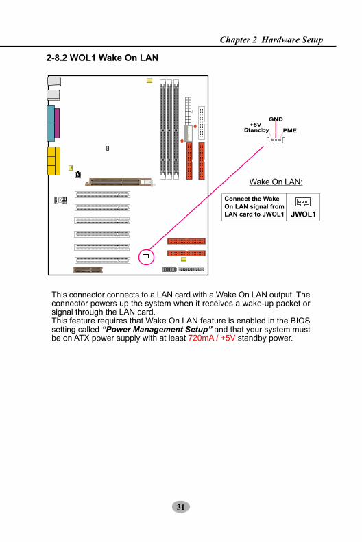
2-8.2 WOL1 Wake On LAN
This connector connects to a LAN card with a Wake On LAN output. Theconnector powers up the system when it receives a wake-up packet orsignal through the LAN card.This feature requires that Wake On LAN feature is enabled in the BIOSsetting called “Power Management Setup” and that your system mustbe on ATX power supply with at least 720mA / +5V standby power.
GND
PME�
+5VStandby
Connect the WakeOn LAN signal fromLAN card to JWOL1 JWOL1
Wake On LAN:
32
Series SL-85SD
1
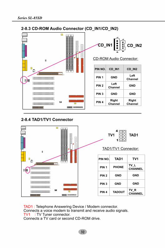
2-8.4 TAD1/TV1 Connector
2-8.3 CD-ROM Audio Connector (CD_IN1/CD_IN2)
PIN NO.
PIN 1 GND
PIN 2
GNDPIN 3
RightChannel
PIN 4
LeftChannel
CD_IN1 CD_IN2
GND
GND
RightChannel
LeftChannel
CD-ROM Audio Connector:
TAD1/TV1 Connector:
TAD1 : Telephone Answering Device / Modem connector.Connects a voice modem to transmit and receive audio signals.TV1 : TV Tuner connector.Connects a TV card or second CD-ROM drive.
CD_IN2CD_IN11 4
1 4
1
PIN NO.
PIN 1 PHONE
PIN 2
GNDPIN 3
TADOUTPIN 4
GND
TAD1 TV1
GND
GND
TV_RCHANNEL
TV_LCHANNEL
1
4
TV1 TAD1
33
Chapter 2 Hardware Setup
1
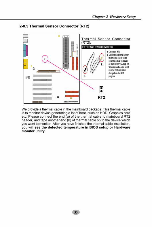
2-8.5 Thermal Sensor Connector (RT2)
a: Connect to RT2.b: Connect this thermal sensor to particular device which generates lots of heat such as Hard Driver, VGA chip, etc. When connected, user could observe the temperature change from the BIOS program.
RT2: THERMAL SENSOR CONNECTOR
We provide a thermal cable in the mainboard package. This thermal cableis to monitor device generating a lot of heat, such as HDD, Graphics cardetc. Please connect the end (a) of the thermal cable to mainboard RT2header, and tape another end (b) of thermal cable on to the device whichyou want to monitor. After you have finished the thermal cable installation,you will see the detected temperature in BIOS setup or Hardwaremonitor utility.
Thermal Sensor Connector(RT2):
RT2
34
Series SL-85SD
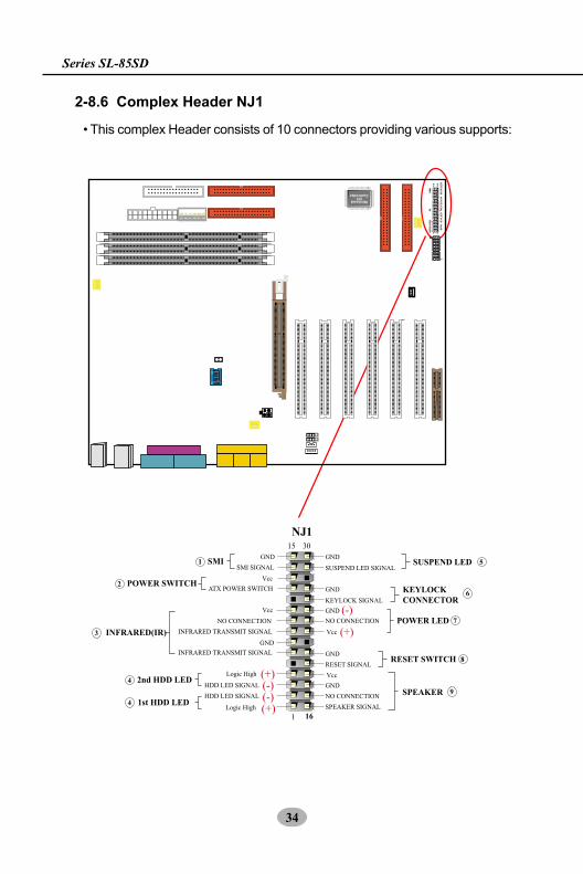
2-8.6 Complex Header NJ1
• This complex Header consists of 10 connectors providing various supports:
SP
KS
3/L
ED
KE
YL
OC
KS
US
/LE
D
HD
D/L
ED
IRS
MI
++
--
+-
1 1
5�
1 1
5
Winbond � I/O � Controller
1
16
1
ON
DIP
�
1
15 30
(+)
(+)
(-)(-)
(+)
(-)
Logic High
Logic High
SPEAKER SIGNAL
NO CONNECTION
GND
RESET SIGNAL
GND
Vcc
NO CONNECTION
GND
KEYLOCK SIGNAL
GND
SUSPEND LED SIGNAL
GND
Vcc
Vcc
ATX POWER SWITCH
Vcc
SMI SIGNAL
GND
HDD LED SIGNAL
HDD LED SIGNAL
GND
NO CONNECTION
INFRARED TRANSMIT SIGNAL
INFRARED TRANSMIT SIGNAL
1st HDD LED
2nd HDD LED
INFRARED(IR)
POWER SWITCH
SMI
SPEAKER
RESET SWITCH
POWER LED
KEYLOCKCONNECTOR
SUSPEND LED
NJ1
9
8
7
6
5
4
4
3
2
1
16
35
Chapter 2 Hardware Setup
6. Keylock Connector: CONNECTION: Connected to keylock switch. FUNCTION: To lock keyboard for security purpose.
7. Power LED Connector: CONNECTION: Connected to System Power LED. FUNCTION: To supply power to “System Power LED”.
8. Reset Switch Connector: CONNECTION: Connected to the case-mounted “Reset Switch”. FUNCTION: To supply power to “Reset Switch” and support system reboot function.
9. Speaker Connector: CONNECTION: Connected to the case-mounted Speaker. FUNCTION: To supply power to the case-mounted Speaker.
1. SMI Connector (System Management Interrupt): CONNECTION: This 2-pin connector is connected to the case-mounted Suspend Switch. FUNCTION: Manually placing the system into a Suspend mode or “Green” mode.
2. Power Switch Connector: CONNECTION: Connected to a momentary button or switch. FUNCTION: Manually switching the system between “On” and “Soft Off”. Pressing the momentary button for more than 4 seconds will also turn the system off.
3. IR Connector (Infrared Connector): CONNECTION: Connected to Connector IR on board. FUNCTION: Supporting wireless transmitting and receiving module on board.
4. 1st HDD LED Connector / 2nd HDD LED Connector: CONNECTION: Connected to HDD LED. FUNCTION: To supply power to HDD LED.
5. Suspend LED Connector: CONNECTION: Connected to Suspend indicator. FUNCTION: To supply power to “Suspend indicator”.
36
Series SL-85SD
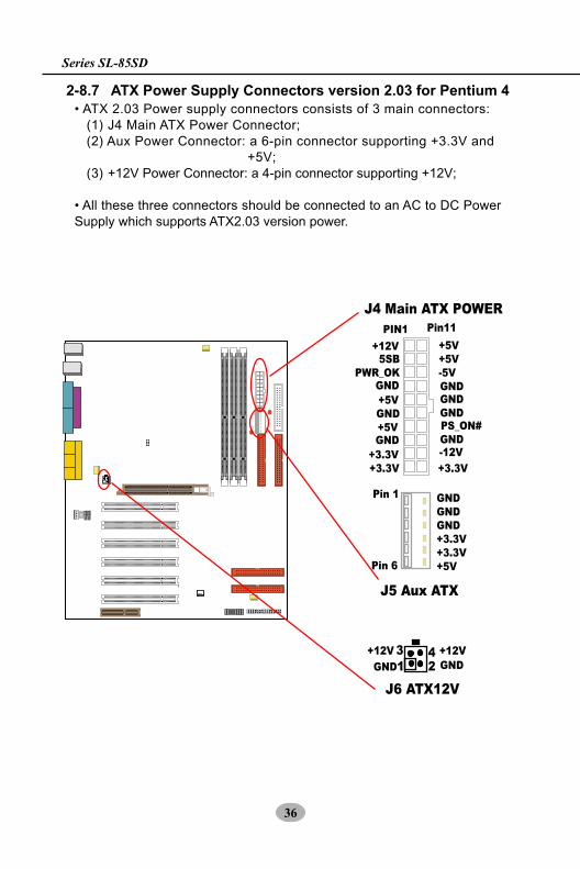
2-8.7 ATX Power Supply Connectors version 2.03 for Pentium 4• ATX 2.03 Power supply connectors consists of 3 main connectors: (1) J4 Main ATX Power Connector; (2) Aux Power Connector: a 6-pin connector supporting +3.3V and +5V; (3) +12V Power Connector: a 4-pin connector supporting +12V;
• All these three connectors should be connected to an AC to DC PowerSupply which supports ATX2.03 version power.
1
J6 ATX12V
1 23 4
J4 Main ATX POWER
J5 Aux ATX
Pin11
GNDGNDGND+3.3V+3.3V+5V
Pin 1
Pin 6
+12V
GND GND+12V
+3.3V+3.3V
GND+5VGND+5VGND
PWR_OK5SB
+12V
+3.3V
-12VGNDPS_ON#GNDGNDGND-5V+5V+5V
PIN1
37
Chapter 2 Hardware Setup
CNR slot
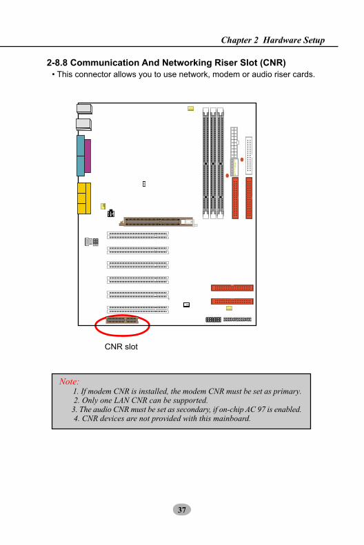
2-8.8 Communication And Networking Riser Slot (CNR)• This connector allows you to use network, modem or audio riser cards.
Note: 1. If modem CNR is installed, the modem CNR must be set as primary. 2. Only one LAN CNR can be supported. 3. The audio CNR must be set as secondary, if on-chip AC 97 is enabled. 4. CNR devices are not provided with this mainboard.
1
38
Series SL-85SD
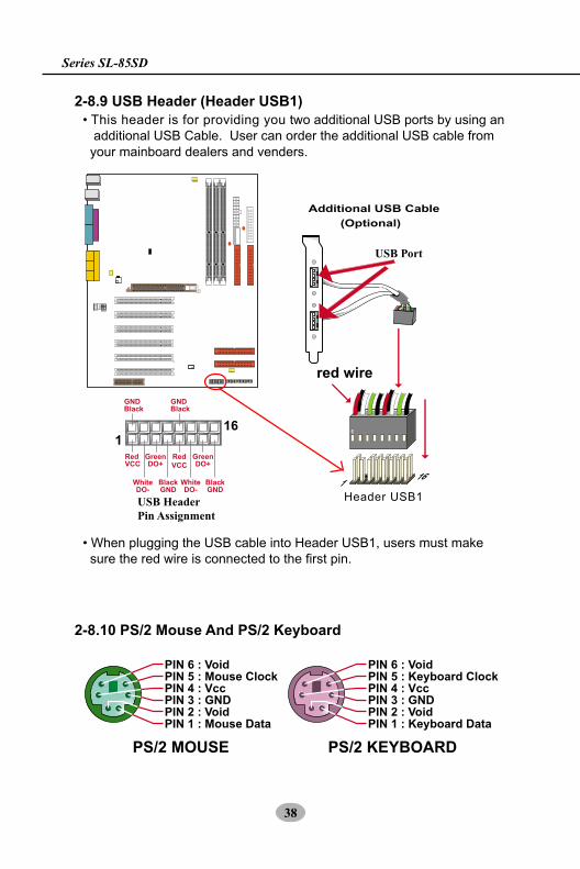
PIN 6 : VoidPIN 5 : Mouse ClockPIN 4 : VccPIN 3 : GNDPIN 2 : VoidPIN 1 : Mouse Data
PS/2 MOUSE
PIN 6 : VoidPIN 5 : Keyboard ClockPIN 4 : VccPIN 3 : GNDPIN 2 : VoidPIN 1 : Keyboard Data
PS/2 KEYBOARD
• When plugging the USB cable into Header USB1, users must make sure the red wire is connected to the first pin.
2-8.9 USB Header (Header USB1)• This header is for providing you two additional USB ports by using an additional USB Cable. User can order the additional USB cable from your mainboard dealers and venders.
2-8.10 PS/2 Mouse And PS/2 Keyboard
Header USB1
�1
16��
Red�VCC
Green�DO+
Green�DO+
White�DO-
White�DO-
Black�GND
Black�GND
Red�VCC
GND�Black
GND�Black
116�
�
1 �
Additional USB Cable
(Optional)
red wire
USB Header�Pin Assignment
USB Port
1
39
Chapter 2 Hardware Setup
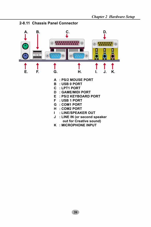
2-8.11 Chassis Panel Connector
A.
E. F. G. H. I. J. K.
B. C. D.
A : PS/2 MOUSE PORTB : USB 0 PORTC : LPT1 PORTD : GAME/MIDI PORTE : PS/2 KEYBOARD PORTF : USB 1 PORTG : COM1 PORTH : COM2 PORTI : LINE/SPEAKER OUTJ : LINE IN (or second speaker out for Creative sound)K : MICROPHONE INPUT
40
Series SL-85SD
IRQJ 0J System TimerJJ 1
IRQJJ Function DescriptionJ Priority
IRQJ 1J Keyboard ControllerJ 2
IRQJ 2J Programmable InterruptJ N/A
IRQJ 3J Serial Port (COM 2)J 11
IRQJ 4J Serial Port (COM 1)J 12
IRQJ 5J FreeJ 13
IRQJ 6J Floppy Disk ControllerJ 14
IRQJ 7J Parallel Port (LPT1)J 15
IRQJ 8J Real Time Clock (RTC)J 3
IRQJ 9J FreeJ 4
IRQJ 10J FreeJ 5
IRQJ 11J FreeJ 6
IRQJ 12J PS/2 Mouse PortJ 7
IRQJ 13J CoprocessorJ 8
IRQJ 14J Primary IDE ChannelJ 9
IRQJ 15J Secondary IDE ChannelJ 10
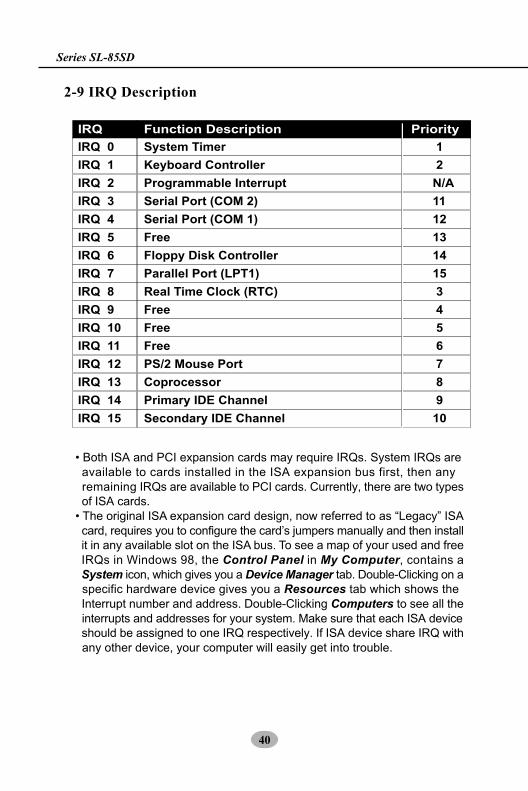
2-9 IRQ Description
• Both ISA and PCI expansion cards may require IRQs. System IRQs are available to cards installed in the ISA expansion bus first, then any remaining IRQs are available to PCI cards. Currently, there are two types of ISA cards.• The original ISA expansion card design, now referred to as “Legacy” ISA card, requires you to configure the card’s jumpers manually and then install it in any available slot on the ISA bus. To see a map of your used and free IRQs in Windows 98, the Control Panel in My Computer, contains a System icon, which gives you a Device Manager tab. Double-Clicking on a specific hardware device gives you a Resources tab which shows the Interrupt number and address. Double-Clicking Computers to see all the interrupts and addresses for your system. Make sure that each ISA device should be assigned to one IRQ respectively. If ISA device share IRQ with any other device, your computer will easily get into trouble.

41
Chapter 2 Hardware Setup
MEMOMEMO
Series SL-85SD
42
Chapter 3 Software Setup
3-1 Intel Chipset Software Installation Utility ( INF Utility )
3-2 Intel Application Accelerator ( IAA )
3-3 AC’97 Audio CODEC Drivers Installation
(For SL-85SD and SL-85SD-X ONLY)
3-4 Creative Sound Drivers Installation
(For SL-85SD+, SL-85SD+-X, SL-85SDB AND
SL-85SDB-X ONLY)
3-5 Windbond Hardware Monitor Utility
3-6 Promise RAID Drivers Installation
(for SL-85SD and SL-85SD-X only)
This chapter is devoted to describing the installations of all these essentialdrivers and utilities, and users are recommended to take the following in-stallation orders :
Drivers, Utilities and Software Installation
• This mainboard should always be shipped with a Support CD which con- tains those necessary driver files, Application Softwares and some help- ful utilities.• For Series SL-85SD, user should be able to find in the Supported CD the following drivers and utilities supported by Intel 845 Chipset: 1. INF Utility ( Intel Chipset Software Installation Utility; 2. Intel Application Accelerator ( IAA ); 3. Creative Audio drivers; 4. AC’97 Drivers; 5. Hardware Monitor Utility; • For SL-85SD+ and SL-85SD+-X, a floppy diskette containing Promise RAID Drivers wil also be added to the package for the IDE RAID setup.
Chapter 3 Software Setup
43
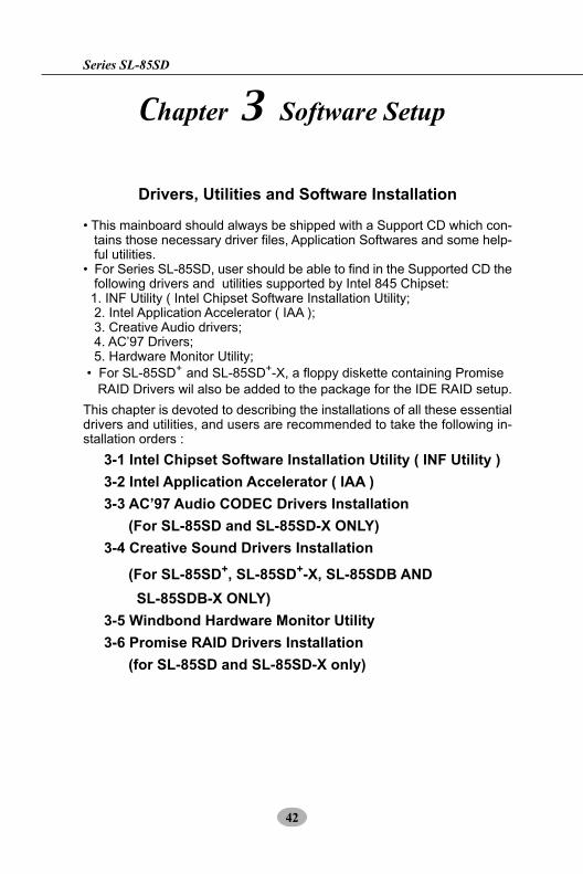
3-1 Install “Intel Chipset Software Installation Utility”
7• After all the setup process is finished, please restart your computer by clicking on “Finish” so as to take the Utility into effect.
3• Click on the “Intel Chipsets Drivers”. 4
• Click on “Intel 845 Chipset”and then “Intel chipset soft-ware Installation Utility” tostart installation.
• Please put the Support CDprovided for SL-85SD seriesinto your CD-ROM drive.
1• When a “Welcome” win-dow a p p e a r s o n t h escreen, choose “InstallChipset Drivers”.
2
• On the “InstallShieldWizard” screen, press“ N e x t ” b u t t o n t ocontinue.
5
Next
6• On the “Licence Agree-ment” screen, press “Yes”to accept Software LicenseAgreement.
Yes
Finish

Series SL-85SD
44
3-2 Install “Intel Application Accelerator”:
4• Click on the “Intel 845Chipset”, and then “”IntelApplication Accelerator” tostart installation.
3• Click on the “Intel Chipset Drivers”.
•On the “InstallShield Wizard”screen, Click on “Next” tocontinue.
5 • On the “Licence Agree-ment” screen, click on “Yes” to continue.
7 • On”Choose DestinationLocation” screen, press“Yes” to continue.
• Please put the Support CD provided for SL-85SD series into your CD-ROM drive.
1• When a “Welcome” win- dow appears on the screen, choose “Install Drivers”.
2
6
IAA supports all Windows 98/98se/Mellennium/NT4/2000 with PentiumIII / 4 processor. Installation of this software for these operating systemsare similarly fully automated by itself, and it is typically designed toimprove performance of the storage sub-system and overall systemperformance.Below is a model installation on Windows Me. Users of Windows 98/98se/NT4/2000 can also follow this example for their IAA installation.
Next Yes
• On”InstallShield WizardComplete” screen, choose“Yes, I want to restart mycomputer now” and press“finish” to restart. Remem-ber you must restart com-puter to put setup in effect.
8
Yes, I want to restart my computer now
Finish
C:\Program Files\Intel\Intel Application Accelerator
Yes
Chapter 3 Software Setup
45
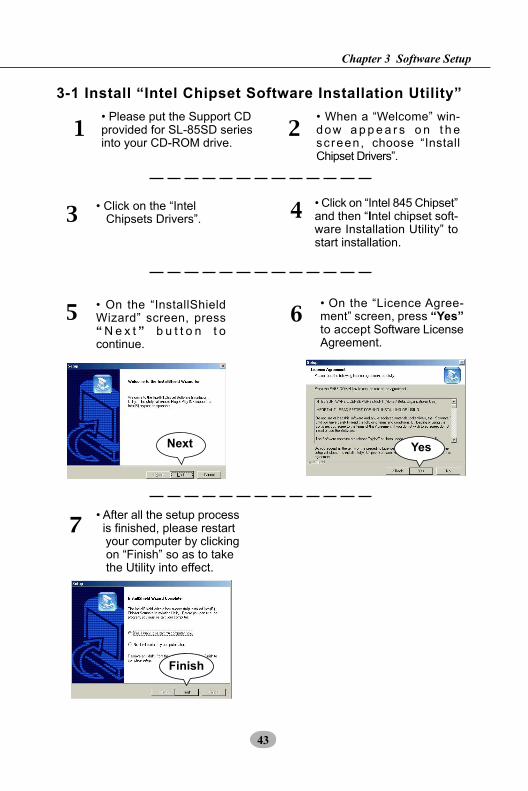
3-3 AC’97 DRIVER INSTALLATION AC’97 Sound Controller is installed on SL-85SD and SL-85SD- X only)
• Click on the “INTEL 845 Chipsets”.
• Click on the “INTEL Driver”.
43
7 • Press “Next” to continue.
Next
8• After all the setup process is finished, please restart your computer by clicking on ”Finish”.
OK
• Click on the “AC’97 Driver”.5 6
• The next screen will appearfor user to select which AC’97driver you need to install de-pending on what operationsystem you are using. Sup-posing that your system isWindows 98SE/ME/Win2000,then click on the “InstallAC’97 Driver for Win98SE/ME/Win2000 ”.
• Please put the Support CD provided in your mainboard package into the CD-ROM drive.
1• When a welcome window appears on the screen, users should choose “Install Driver”.
2
Series SL-85SD
46
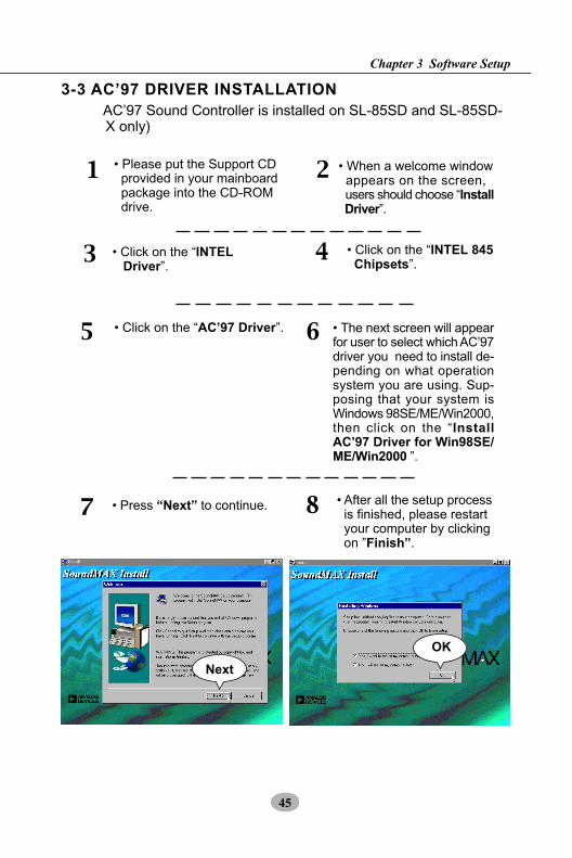
3-4 Creative Sound Driver Installation
Creative Sound is built on SL-85SD+, SL-85SD+-X, SL-85SDB, and SL-85SDB-X only.
3-4.1 To Install Creative Sound Driver
• Please put the Support CD provided in your mainboard package into the CD-ROM drive.
1• When a welcome window appears on the screen, users should choose “Install Driver”.
2
3• Click on the “INTEL Driver”. 4
• Click on the “INTEL 845 Chipsets”.
5• Click on the “Creative Sound Driver” to start.
6
• Follow the instructions on screens to complete the installation, after which please restart your PC to put the driver into effect.
• When the Licence Agree- ment screen appears, you must clik to “Yes” to con tinue installation.
7
Chapter 3 Software Setup
47
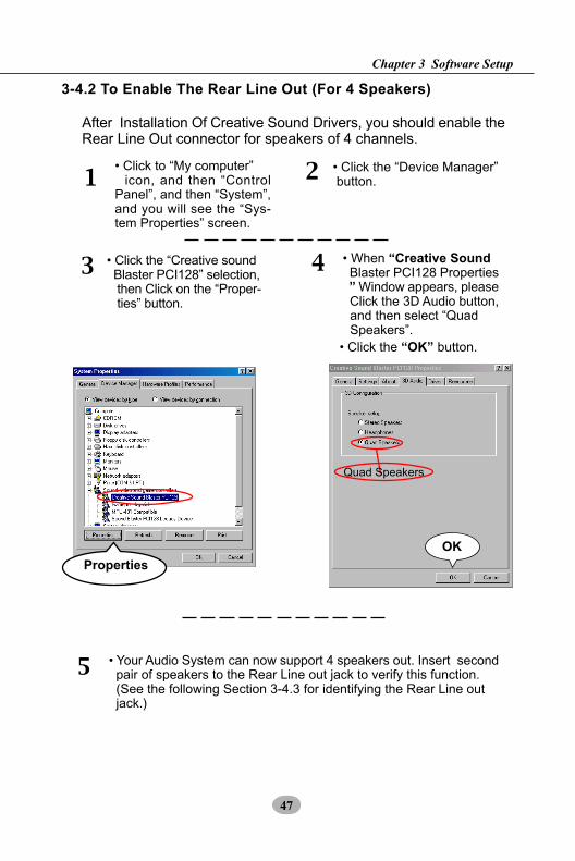
• When “Creative Sound Blaster PCI128 Properties ” Window appears, please Click the 3D Audio button, and then select “Quad Speakers”.
4
• Click the “OK” button.
OK
• Your Audio System can now support 4 speakers out. Insert second pair of speakers to the Rear Line out jack to verify this function. (See the following Section 3-4.3 for identifying the Rear Line out jack.)
5
• Click to “My computer” icon, and then “ControlPanel”, and then “System”,and you will see the “Sys-tem Properties” screen.
1• Click the “Device Manager” button.2
3• Click the “Creative sound Blaster PCI128” selection, then Click on the “Proper- ties” button.
3-4.2 To Enable The Rear Line Out (For 4 Speakers)
After Installation Of Creative Sound Drivers, you should enable theRear Line Out connector for speakers of 4 channels.
Properties
Quad Speakers
Series SL-85SD
48
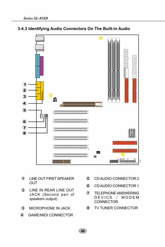
3-4.3 Identifying Audio Connectors On The Built-in Audio
LINE OUT FIRST SPEAKEROUT
1
LINE IN REAR LINE OUTJACK (Second pair ofspeakers output)
2
MICROPHONE IN JACK3
GAME/MIDI CONNECTOR4
TV TUNER CONNECTOR8
TELEPHONE ANSWERINGD E V I C E / M O D E MCONNECTOR.
7
CD AUDIO CONNECTOR 16
CD AUDIO CONNECTOR 25
SPK S3/LED KEYLOCKSUS/LED
HDD/LED IR SMI+ +- -
+ -
1 15
1 15
W
inb
on
d
I
/O
C
on
tro
lle
r
1
16
1
1
6
7
8
2
3
4
5
Chapter 3 Software Setup
49
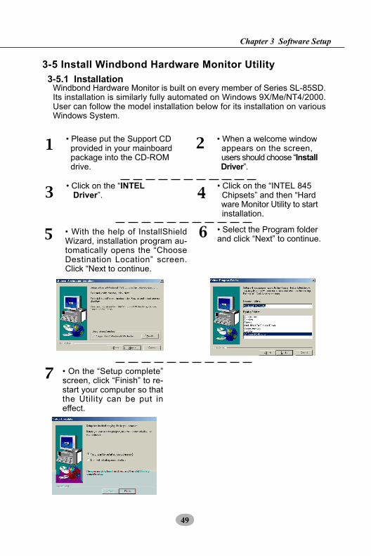
3-5 Install Windbond Hardware Monitor Utility
• With the help of InstallShieldWizard, installation program au-tomatically opens the “ChooseDestination Location” screen.Click “Next to continue.
5
• Click on the “INTEL Driver”.3
• Click on the “INTEL 845 Chipsets” and then “Hard ware Monitor Utility to start installation.
4
• On the “Setup complete”screen, click “Finish” to re-start your computer so thatthe Utility can be put ineffect.
7
• Please put the Support CD provided in your mainboard package into the CD-ROM drive.
1• When a welcome window appears on the screen, users should choose “Install Driver”.
2
6• Select the Program folderand click “Next” to continue.
3-5.1 InstallationWindbond Hardware Monitor is built on every member of Series SL-85SD.Its installation is similarly fully automated on Windows 9X/Me/NT4/2000.User can follow the model installation below for its installation on variousWindows System.

Series SL-85SD
50
• After restarting yourcomputer, click “Start”and choose the pathPrograms\Winbond\Hwdoctorto open the main windowof the Hardware Doctor.
1
3-5.2 Verification
2• The “Voltage/CaseOpen”window is for CPU voltagea n d t e m p e r a t u r einformation.
3 • The “Fan/Temperature”window is for Fan speeda n d t e m p e r a t u r einformation.
• The “CPU/Memory” win-dow is for Processor andmemory information.
4

Chapter 3 Software Setup
51
3-6 Install Promise RAID Controller
Promise RAID Controller is built on all members of Series SL-85SD.Before installing the driver for Promise RAID Controller, please check thefollowing points:(1) Set up Jumper 4 on board to enable Promise RAID Controller.
(2) Get ready the floppy diskette containing the FastTrak100-Lite Drivers for various Windows systems.
(3) The RAID Controller Drivers installation procedures will differ among different operating systems and situations. Please refer to Chapter 5 of this manual to install your RAID drivers and disk arrays.
Series SL-85SD
52
Chapter 4 BIOS Setup
The following topics are included in this chapter:
4-1 About BIOS Setup4-2 To run BIOS Setup4-3 About CMOS4-4 The POST (Power On Self Test)4-5 To upgrade BIOS4-6 BIOS Setup
THE BIOS
• BIOS stands for Basic Input and Output System. It was once called ROM BIOS when it was stored in a Read-Only Memory(ROM) chip Now manufacturers would like to store BIOS in EEPROM which means Electrically Erasable Programmable Memory. BIOS used in this series of mainboard is stored in EEPROM, and is the first program to run when you turn on your computer.• BIOS performs the following functions: 1. Initializing and testing hardware in your computer (a process called “POST”, for Power On Self Test). 2. Loading and running your operating system. 3. Helping your operating system and application programs manage your PC hardware by means of a set of routines called BIOS Run- Time Service.
Chapter 4 BIOS Setup
53
4-1 About BIOS Setup• BIOS setup is an interactive BIOS program that you need to run when: 1. Changing the hardware of your system. (For example: installing a new Hard Disk etc.) 2. Modifying the behavior of your computer. (For example: changing the system time or date, or turning special features on or off etc.) 3. Enhancing your computer’s behavior. (For example: speeding up performance by turning on shadowing or cache)
4-2 To run BIOS Setup• First access BIOS setup menu by pressing < DEL > key after “POST” iscomplete ( before OS is loaded ). BIOS will then display the followingmessage:
Press “DEL” to enter “SETUP”
4-3 About CMOS• CMOS is the memory maintained by a battery. CMOS is used to store the BIOS settings you have selected in BIOS Setup. CMOS also maintains the internal clock. Every time you turn on your computer, the BIOS Looks into CMOS for the settings you have selected and configures your computer accordingly. If the battery runs out of power, the CMOS data will be lost and POST will issue a “CMOS invalid” or “CMOS checksum invalid” message. If this happens, you have to replace the battery and do some proper settings in BIOS Setup.
4-4 The POST ( Power On Self Test )• POST is an acronym for Power On Self Test. This program will test all things the BIOS does before the operating system is started. Each of POST routines is assigned a POST code, a unique number which is sent to I/O port 080h before the routine is executed.
Series SL-85SD
54
4-5 To upgrade BIOS• System BIOS is incorporated into a Flash memory component. Flash BIOS allows user to upgrade BIOS without the need to replace an EPROM component.• The Upgrade Utility can be loaded on a floppy diskette to execute saving, verifying, and updating the system BIOS. The Upgrade Utility can also be run from a hard disk drive or a network drive.
4-5.1 Before Upgrading BIOS• It is highly recommended that you save a copy of the original mainboard BIOS along with a Flash EPROM Programming utility (AWDFLASH.EXE) to a bootable floppy disk so that you can reinstall the BIOS when needed.
4-5.2 Upgrade Process• Normally, to upgrade BIOS is unnecessary if the system is working fine Users should only upgrade the BIOS when you experience incompatible problems or need to create new features.
• “AWDFLASH.EXE” is a Flash EPROM Programming utility that up dates the BIOS by uploading a new BIOS file to the programmable flash ROM on the mainboard. This program only works in DOS environment, the utility can not be executed in win95/98, ME, NT or WINDOWS 2000 environment.
• Please follow the steps below for upgrading the system BIOS:
Step 1. Please visit the board maker’s website, download latest BIOS file and award flash utility “AWDFLASH.EXE”. The BIOS file format will be *.bin, of which “ * ” stands for the specific BIOS file name.
Step 2. Create a bootable diskette. Then copy the BIOS file and award flash utility “AWDFLASH.EXE” into the diskette.
Step 3. Insert the diskette into drive A, reboot your system and boot from the diskette.
Chapter 4 BIOS Setup
55
Step 4. Type awdflash *.bin /sn/py/cc and then press <Enter> to run BIOS upgrade program. (*.bin depends on your mainboard model and version code. Instead of typing “*”, you should type specific file name for your specific mainboard).
Step 5. Please press <F1> or <F10> to exit or reset your system.
Warning ! If the message “ Write Fail ” appears while Award “FLASHMEMORY WRITER” is verifying Flash memory, just repeat the process.Please DO NOT reset or turn off the system. If the award memory flashutility is not able to update the BIOS successfully, your system may not beable to boot up.
Step 6. You will need a message “CMOS checksum error-Default loaded” during booting the system. Press <Del> to run CMOS setup utility, then reload “LOAD SETUP DEFAULTS” or “Load Optimized Defaults” and save this
change.
The parameters of AWDFLASH.EXE
/sn: No original BIOS backup/py: Program flash memory/cc: Clear CMOS data (and update data automatically) after pro- gramming
Users can type AWDFLASH /? to get further details about the parameters.
Incorrect usage of the parameter will damage the BIOS information, so we
strongly recommend user to leave parameters alone unless you fully understand
their function.
Series SL-85SD
56
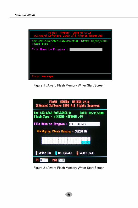
Figure 1 : Award Flash Memory Writer Start Screen
Figure 2 : Award Flash Memory Writer Start Screen
Chapter 4 BIOS Setup
57
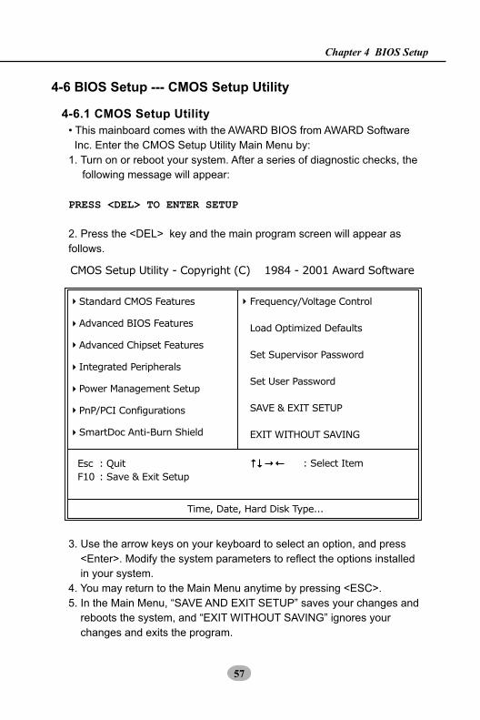
• This mainboard comes with the AWARD BIOS from AWARD Software Inc. Enter the CMOS Setup Utility Main Menu by:1. Turn on or reboot your system. After a series of diagnostic checks, the
following message will appear:
PRESS <DEL> TO ENTER SETUP
2. Press the <DEL> key and the main program screen will appear asfollows.
3. Use the arrow keys on your keyboard to select an option, and press<Enter>. Modify the system parameters to reflect the options installedin your system.
4. You may return to the Main Menu anytime by pressing <ESC>.5. In the Main Menu, “SAVE AND EXIT SETUP” saves your changes and
reboots the system, and “EXIT WITHOUT SAVING” ignores yourchanges and exits the program.
4-6 BIOS Setup --- CMOS Setup Utility
4-6.1 CMOS Setup Utility
CMOS Setup Utility - Copyright (C) 1984 - 2001 Award Software
Standard CMOS Features
Advanced BIOS Features
Advanced Chipset Features
Integrated Peripherals
Power Management Setup
PnP/PCI Configurations
SmartDoc Anti-Burn Shield
Frequency/Voltage Control
Load Optimized Defaults
Set Supervisor Password
Set User Password
SAVE & EXIT SETUP
EXIT WITHOUT SAVING
Esc7 : QuitF107: Save & Exit Setup
Time, Date, Hard Disk Type...
: Select Item
Series SL-85SD
58
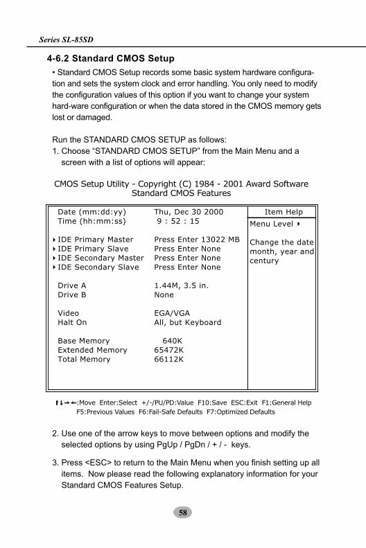
• Standard CMOS Setup records some basic system hardware configura-tion and sets the system clock and error handling. You only need to modifythe configuration values of this option if you want to change your systemhard-ware configuration or when the data stored in the CMOS memory getslost or damaged.
Run the STANDARD CMOS SETUP as follows:1. Choose “STANDARD CMOS SETUP” from the Main Menu and a
screen with a list of options will appear:
4-6.2 Standard CMOS Setup
Date (mm:dd:yy)7 Thu, Dec 30 2000Time (hh:mm:ss)7 9 : 52 : 15
IDE Primary Master7 Press Enter 13022 MBIDE Primary Slave7 Press Enter NoneIDE Secondary Master7 Press Enter NoneIDE Secondary Slave7 Press Enter None
Drive A7 1.44M, 3.5 in.Drive B7 None
Video7 EGA/VGAHalt On7 All, but Keyboard
Base Memory7 640KExtended Memory7 65472KTotal Memory7 66112K
Item Help
Menu Level
Change the datemonth, year andcentury
:Move Enter:Select +/-/PU/PD:Value F10:Save ESC:Exit F1:General HelpF5:Previous Values F6:Fail-Safe Defaults F7:Optimized Defaults
CMOS Setup Utility - Copyright (C) 1984 - 2001 Award SoftwareStandard CMOS Features
2. Use one of the arrow keys to move between options and modify theselected options by using PgUp / PgDn / + / - keys.
3. Press <ESC> to return to the Main Menu when you finish setting up all items. Now please read the following explanatory information for your Standard CMOS Features Setup.

Chapter 4 BIOS Setup
59
Primary / SecondaryMaster / Slave
This field records the specifications for all non-SCSIhard disk drives installed in your system. Refer tothe respective documentation on how to install thedrives.
Time (hh:mm:ss) The time format is based on the 24-hour military-time clock. For example, 1 p.m. is 13:00:00. Pressthe left or right arrow key to move to desired field.Press the PgUp or PgDn key to increment thesetting, or type the desired value into the field.
Date (mm:dd:yy) The BIOS determines the day of the week from theother date information. This field is for informationonly.Press the left or right arrow key to move to the de-sired field (date, month, year). Press the PgUp orPgDn key to increment the setting, or type the de-sired value into the field.
IDE HDD Auto-Detection7 Press Enter
IDE Primary Master7 AutoAccess Mode7 Auto
Capacity7 13022 MB
Cylinder7 25232Head7 16Precomp7 0Landing Zone7 25231Sector7 63
Item Help
Menu Level
CMOS Setup Utility - Copyright (C) 1984 - 2001 Award SoftwareIDE Primary Master
:Move Enter:Select +/-/PU/PD:Value F10:Save ESC:Exit F1:General HelpF5:Previous Values F6:Fail-Safe Defaults F7:Optimized Defaults
Series SL-85SD
60
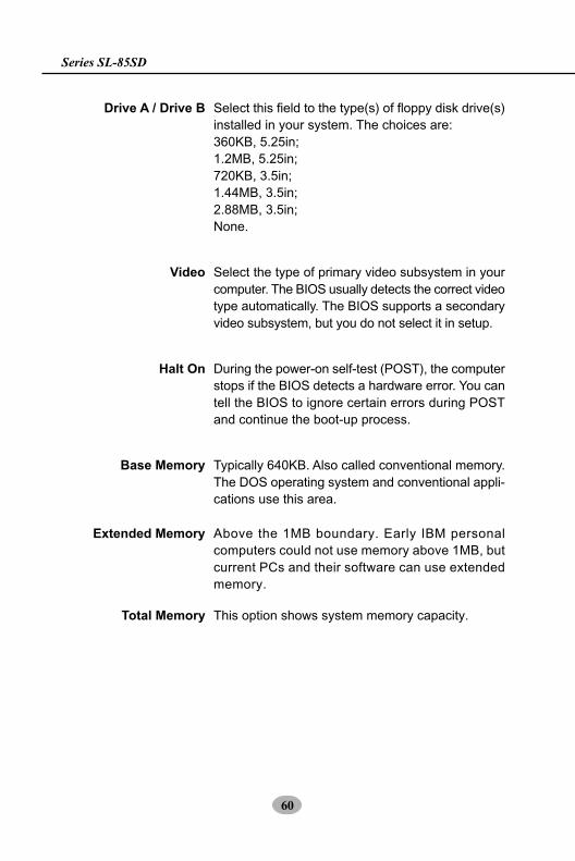
Base Memory Typically 640KB. Also called conventional memory.The DOS operating system and conventional appli-cations use this area.
Extended Memory Above the 1MB boundary. Early IBM personalcomputers could not use memory above 1MB, butcurrent PCs and their software can use extendedmemory.
Total Memory This option shows system memory capacity.
Drive A / Drive B Select this field to the type(s) of floppy disk drive(s)installed in your system. The choices are:360KB, 5.25in;1.2MB, 5.25in;720KB, 3.5in;1.44MB, 3.5in;2.88MB, 3.5in;None.
Video Select the type of primary video subsystem in yourcomputer. The BIOS usually detects the correct videotype automatically. The BIOS supports a secondaryvideo subsystem, but you do not select it in setup.
Halt On During the power-on self-test (POST), the computerstops if the BIOS detects a hardware error. You cantell the BIOS to ignore certain errors during POSTand continue the boot-up process.
Chapter 4 BIOS Setup
61
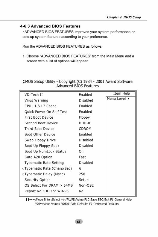
4-6.3 Advanced BIOS Features• ADVANCED BIOS FEATURES improves your system performance orsets up system features according to your preference.
Run the ADVANCED BIOS FEATURES as follows:
1. Choose “ADVANCED BIOS FEATURES” from the Main Menu and ascreen with a list of options will appear:
:Move Enter:Select +/-/PU/PD:Value F10:Save ESC:Exit F1:General HelpF5:Previous Values F6:Fail-Safe Defaults F7:Optimized Defaults
VD-Tech II Enabled
Virus Warning7 Disabled
CPU L1 & L2 Cache7 Enabled
Quick Power On Self Test7 Enabled
First Boot Device7 Floppy
Second Boot Device 7 HDD-0
Third Boot Device7 CDROM
Boot Other Device7 Enabled
Swap Floppy Drive7 Disabled
Boot Up Floppy Seek7 Disabled
Boot Up NumLock Status7 On
Gate A20 Option7 Fast
Typematic Rate Setting7 Disabled
Typematic Rate (Chars/Sec) 6
Typematic Delay (Msec)7 250
Security Option7 Setup
OS Select For DRAM > 64MB Non-OS2
Report No FDD For WIN957 No
Item HelpMenu Level
CMOS Setup Utility - Copyright (C) 1984 - 2001 Award SoftwareAdvanced BIOS Features

Series SL-85SD
62
Quick Power On SelfTest
Select Enabled to reduce the amount of time required torun the power-on self-test (POST). A quick POST skipscertain steps. We recommend that you normally enablequick POST.
2. Use one of the arrow keys to move between options and modify theselected options by using PgUp / PgDn / + / - keys. An explanation ofthe <F> keys follows:
<F1>: “Help” gives options available for each item.<F5>: Get the previous values. These values are the values with which
the user starts the current session.<F6>: Load all options with the BIOS default values.<F7>: Load all options with the Setup default values.
Virus Warning When enabled, you receive a warning message if aprogram (specifically, a virus) attempts to write to theboot sector or the partition table of the hard disk drive.You should then run an antivirus program. Keep inmind that this feature protects only the boot sector,not the entire hard drive.
NOTE: Many disk diagnostic programs that access the boot sector table
can trigger the virus warning message. If you plan to run such a
program, we recommend that you disable the virus warning.
CPU L1 & L2 Cache Cache memory is additional memory that is muchfaster than conventional DRAM (system memory).CPUs from 486-type up contain internal cachememory (L1), and most, but not all, modern PCshave external cache memory (L2). When the CPUrequests data, the system transfers the requesteddata from the main DRAM into cache memory, forfaster access by the CPU.
3. Press <ESC> to return to the Main Menu when you finish setting up allitems. Now please read the following information for the “AdvanceBIOS Features “ setup:
Chapter 4 BIOS Setup
63
Swap Floppy Drive When enabled, floppy drives A and B will be exchangingwithout any physical connection and modification on thecables.
First/Second/Third/Other Boot Device
The BIOS attempts to load the operating system fromthe devices according to your selected priority.The choices: Floppy; LS120; HDD-0;SCSI; CDROM;HDD-1;HDD-2;HDD-3; ZIP100;LAN;RAID;Disabled.
Boot Up Floppy Seek When enabled, the BIOS tests (seeks) floppy drivesto determine whether they have 40 or 80 tracks. Only360-KB floppy drives have 40 tracks; drives with270KB, 1.2MB, and 1.44MB capacity all have 80tracks. Because very few modern PCs have 40-trackfloppy drives, we recommend that you set this fieldto disabled to save time.
Boot Up NumLockStatus
Toggle between On or Off to control the state ofthe NumLock key when the system boots. If On,the numeric keypad is in numeric mode. If off, thenumeric keypad is in cursor control mode.
Gate A20 Option Gate A20 refers to the way the system addressesmemory above 1 MB (extended memory). Whenset to Fast, the system chipset controls Gate A20.When set to Normal, a pin in the keyboard control-ler controls Gate A20. Setting Gate A20 to Fastimproves system speed, particularly with OS/2 andWindows.
Boot Other Device When enabled, this item allows you to select other bootdevice. The choices: Enabled; Disabled
Series SL-85SD
64
OS Select For DRAM >64MB
Select OS2 only if you are running OS/2 operatingsystem with greater than 64MB of RAM on yoursystem. Default is “Non-OS2”.
Security Option If you have set a password, select whether thepassword is required every time the Systemboots, or only when you enter setup.The choices: system; setup (default).
Report No FDD ForWin95
Yes: BIOS reports “NO FDD” to Win95.No (default): BIOS will not report “NO FDD” to Win95.
Typematic Rate Setting When Disabled, the following two items (Typematic Rateand Typematic Delay) are irrelevant. Keystroke repeatsat a rate determined by the keyboard controller in yoursystem.When Enabled, you can select a typematic rate andtypematic delay.
Typematic Rate (Chars/ Sec)
When the typematic rate setting is enabled, you canselect a typematic rate (the rate at which characterrepeats when you hold down a key) of 6, 8, 10, 12,15, 20, 24, or 30 characters per second. Default is”disabled”.
Typematic Delay(Msec)
Choices: 250; 500; 750; 1000. This option sets thetime interval for displaying the first and the secondcharacters. If enabled, the time interval is optional.
Chapter 4 BIOS Setup
65
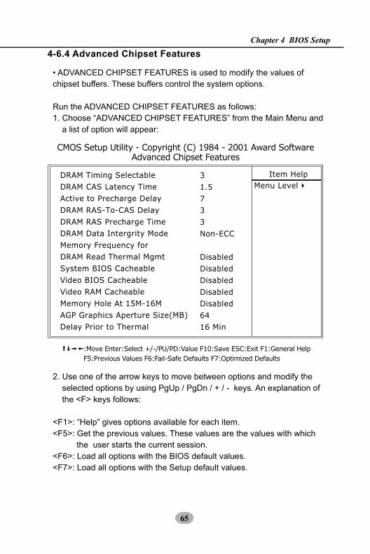
• ADVANCED CHIPSET FEATURES is used to modify the values ofchipset buffers. These buffers control the system options.
Run the ADVANCED CHIPSET FEATURES as follows:1. Choose “ADVANCED CHIPSET FEATURES” from the Main Menu and
a list of option will appear:
4-6.4 Advanced Chipset Features
DRAM Timing SelectableDRAM CAS Latency TimeActive to Precharge DelayDRAM RAS-To-CAS DelayDRAM RAS Precharge TimeDRAM Data Intergrity ModeMemory Frequency forDRAM Read Thermal MgmtSystem BIOS CacheableVideo BIOS CacheableVideo RAM CacheableMemory Hole At 15M-16MAGP Graphics Aperture Size(MB)Delay Prior to Thermal
Item HelpMenu Level
:Move Enter:Select +/-/PU/PD:Value F10:Save ESC:Exit F1:General HelpF5:Previous Values F6:Fail-Safe Defaults F7:Optimized Defaults
31.5733Non-ECC
DisabledDisabledDisabledDisabledDisabled6416 Min
CMOS Setup Utility - Copyright (C) 1984 - 2001 Award SoftwareAdvanced Chipset Features
2. Use one of the arrow keys to move between options and modify theselected options by using PgUp / PgDn / + / - keys. An explanation ofthe <F> keys follows:
<F1>: “Help” gives options available for each item.<F5>: Get the previous values. These values are the values with which
the user starts the current session.<F6>: Load all options with the BIOS default values.<F7>: Load all options with the Setup default values.

Series SL-85SD
66
DRAM RAS# to CAS#Delay
This field lets you insert a timing delay between theCAS and RAS strobe signals, used when DRAM iswritten to, read from, or refreshed. Fast gives fasterperformance and Slow gives more stableperformance. This field applies only when synchro-nous DRAM is installed in the system.The Choices: 2; 3
CAS Latency Time When synchronous DRAM is installed, the numberof clock cycles of CAS latency depends on theDRAM timing. Do not reset this field from the de-fault value specified by the system designer.
DRAM Data integritymodee
This item is to choose or not the Error Check andCorrection mode.Choices are: ECC; Non-ECC (default).
DRAM RAS Precharge If an insufficient number of cycles is allowed for theRAS to accumulate its charge before DRAM refresh,the refresh may be incomplete and the DRAM mayfail to retain data. Fast gives faster performance;and Slow gives more stable performance. This fieldapplies only when synchronous DRAM is installedin the system.The Choices: 2; 3
DRAM Read ThermalMgmt
Selecting Enabled is to activate the DRAM ReadThermal management function. default: Ddisabled.
3. Press <ESC> to return to the Main Menu when you finish setting up allitems. Now please read the following information for the “AdvancedChipset Features” setup:
DRAM Timing Select-able
Select the
Active to PrechargeDelay
This field allows you to select a CAS Precharge delaytiming.Choices are: 7; 6; 5;
Chapter 4 BIOS Setup
67
AGP Graphics Aper-ture Size
Choices: 32; 64 MB. Memory mapped and graphicsdata structures can reside in a Graphics Aperture.This area is like a linear buffer. BIOS will automati-cally report the starting address of this buffer to theO.S.
Delay Prior to Thermal The chipset has an embedded 32-bit posted writebuffer to support delay transactions cycles.This item allows you to choose a delay timing be-fore a new Thermal reading is taken.
Memory Hole At 15M-16M
You can reserve this area of system memory for ISAadapter ROM. When this area is reserved, it can-not be cached.
Video BIOS Cacheable Selecting Enabled allows caching of the systemBIOS ROM at C0000h to C7FFFh, resulting in videoperformance. However, if any program writes to thismemory area, a system error may result.
System BIOSCacheable
Selecting Enabled allows caching of the systemBIOS ROM at F0000h to FFFFFh, resulting in bet-ter system performance.Default: Disabled
Series SL-85SD
68
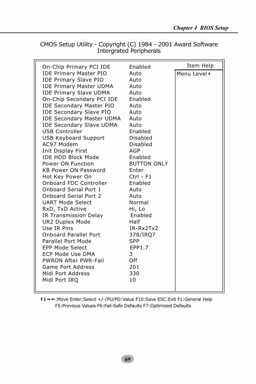
• INTEGRATED PERIPHERALS option allows you to get some informa-tion inside your system when it is working.
Run the INTEGRATED PERIPHERALS as follows:
1. Choose “INTEGRATED PERIPHERALS” from the Main Menu and alist of options will appear:
2. Use one of the arrow keys to move between options and modify theselected options by using PgUp / PgDn / + / - keys. An explanation ofthe <F> keys follows:
<F1>: “Help” gives options available for each item.<F5>: Get the previous values. These values are the values with which
the user starts the current session.<F6>: Load all options with the BIOS default values.<F7>: Load all options with the Setup default values.
4-6.5 Integrated Peripherals
3. Press <ESC> to return to the Main Menu when you finish setting up allitems. please read the following “Integrated Peripherals” menu andthe explanatory information for your “Integrated peripherals” setup:
Chapter 4 BIOS Setup
69
On-Chip Primary PCI IDE7 EnabledIDE Primary Master PIO7 AutoIDE Primary Slave PIO7 AutoIDE Primary Master UDMA7 AutoIDE Primary Slave UDMA7 AutoOn-Chip Secondary PCI IDE 7 EnabledIDE Secondary Master PIO7 AutoIDE Secondary Slave PIO7 AutoIDE Secondary Master UDMA7 AutoIDE Secondary Slave UDMA7 AutoUSB Controller7 EnabledUSB Keyboard Support7 DisabledAC97 Modem7 DisabledInit Display First7 AGPIDE HDD Block Mode7 EnabledPower ON Function7 BUTTON ONLYKB Power ON Password7 EnterHot Key Power On7 Ctrl - F1Onboard FDC Controller7 EnabledOnboard Serial Port 17 AutoOnboard Serial Port 27 AutoUART Mode Select 7 NormalRxD, TxD Active Hi, LoIR Transmission Delay EnabledUR2 Duplex Mode 7 HalfUse IR Pins IR-Rx2Tx2Onboard Parallel Port 7 378/IRQ7Parallel Port Mode7 SPPEPP Mode Select EPP1.7ECP Mode Use DMA7 3PWRON After PWR-Fail7 OffGame Port Address7 201Midi Port Address7 330Midi Port IRQ7 10
Item Help
Menu Level
CMOS Setup Utility - Copyright (C) 1984 - 2001 Award SoftwareIntergrated Peripherals
:Move Enter:Select +/-/PU/PD:Value F10:Save ESC:Exit F1:General HelpF5:Previous Values F6:Fail-Safe Defaults F7:Optimized Defaults
Series SL-85SD
70
PrimaryMaster / Slave UDMA
SecondaryMaster / Slave UDMA
Ultra DMA33/66/100 implementation is possible onlyif your IDE hard drive supports it, if the operatingenvironment includes a DMA drive, and if yoursystem software supports Ultra DMA33/66/100.Select “Auto” to enable BIOS support.The choices: Auto; Disabled.
PrimaryMaster / Slave PIO
SecondaryMaster / Slave PIO
Choose Auto or Mode 0~4. The BIOS will detect theHDD mode type automatically when you chooseAuto. You need to set to a lower mode than Autowhen your hard disk becomes unstable.The choices: Auto; Mode 0; Mode 1; Mode 2; Mode 3; Mode 4.
USB Controller Select Enabled if your system contains a UniversalSerial Bus (USB) controller and you have USBperipherals.
Init Display First Initialize the AGP or PCI slot before initializing anyother display device on the system. The Coices are:AGP; PCI Slot
USB Keyboard Sup-port
Select Enabled if your system contains a UniversalSerial Bus (USB) controller and you have a USBkeyboard.
On-Chip Primary/Secondary PCI IDE
The chipset contains a PCI IDE interface with supportfrom two IDE channels. Select Enabled to activatethe first and/or the second IDE interface. SelectDisabled to inactivate an interface if you install aprimary and/or second add-on IDE interface.The choices: Enabled; Disabled.
AC’97 Modem This option allows you to decide to enable/disablethe 845 chipset to support AC’97 Modem.The choices: Auto; Disabled (default)
Chapter 4 BIOS Setup
71
Onboard SerialPort 1 / Port 2
Select a logical COM port name and matchingaddress for the first and second serial ports.Select an address and corresponding interruptfor the first and second serial ports. Choices:Auto(default); Disabled; 3F8/IRQ4; 2F8/IRQ3;2E8/IRQ3.
UART Mode Select The serial ports on your system offer a variety ofinfrared port modes of the Universal Asynchro-nous Receiver/Transmitter.The choices: Normal; IrDA; ASKIR
IDE HDD Block Mode Block mode is also called block transfer, multiplecommands, or multiple sector read/write. If your IDEhard drive supports block mode (most new drivesdo), select Enabled for automatic detection of theoptimal number of block read/write per sector thedrive can support.The choices: Enabled; Disabled.
Power ON Function This option allows you to select <KB Power ONPassword> , <Hot-Key Power ON> or others.The choices: Any Key, Button only, Keyboard 98,Password, Hot-Key, Mouse Move, Mouse Click.
Onboard FDCController
Select Enabled if your system has a floppy drivecontroller (FDC) installing in the system board andyou want to use it. If you install add-in FDC or yoursystem has no floppy drive, select Disabled.The choices: Enabled (default); Disabled.
KB Power ON Pass-word
When user sets a password for keyboard, the pass-word user set that return the system to Full On state.
Hot-Key Power ON Boot up the system via predetermined keyboard hotkey.The choices: <Ctrl>+<F1>...<F12>
RxD, TxD Active This item allows you to select the correct settingof the Receive Data and Transmit Data signalsfor your IR peripherals.The choices: Hi,Lo (default); Lo, Hi; Lo, Lo; Hi, Hi;.
Series SL-85SD
72
Parallel Port Mode Select an operating mode for the on-board parallel(printer) port. Select Normal, Compatible, or SPPunless you are certain your hardware and softwareboth support one of the other available modes.
Onboard Parallel Port This item allows you to determine onboard parallelport controller I/O address setting.The choices: 378H/IRQ7; 278H/IRQ5; 3BC/IRQ7; Disabled.
Ir Transmission delay This item allows you to Enable/Disable the IrTransmission Delay.The choices: Enabled (default); Disabled.
PWRON After PWR-Fail
Off: Disable Power Lost Resume function.On: Enable Power Lost Resume function.Former Sts: Use Former status.The choices: Off(default); On; Former Sts.
ECP Mode Use DMA Select a DMA channel for the Enhanced Communi-cation port. Choices:3 (default); 1;
Game Port Address This item allows you to select the Game PortAddress.The choices: Disabled; 201(default); 209
EPP Mode Select Select a mode of data transfer of the EnhancedParallel port for your parallel devices.Choices: EPP1.7(default; EPP1.9;
MIDI Port Address Select a DMA channel for the parallel port for useduring ECP mode.The choices: Disabled; 330(default); 300
MIDI Port IRQ This item allows you to select the MIDI Port IRQ.Choices: 10(default); 5;
Use IR Pins To select the correct setting of RxD, TxD signalsof your IR peripherals. You may also refer to yourIR peripherals document for the correct setting.The choices: IR-Rx2Tx2 (default); RxD2, TxD2;
UR2 Duplex Mode This item allows you to select the IR half / fullduplex function.The choices: Half; Full.
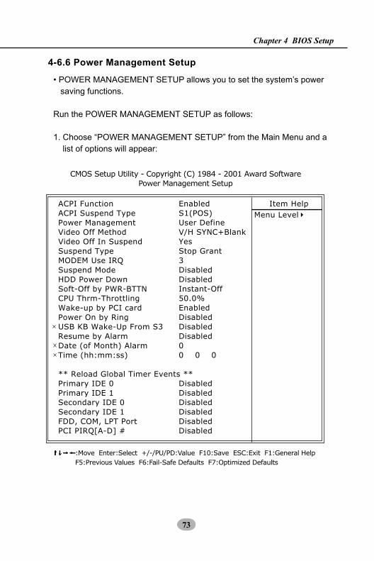
Chapter 4 BIOS Setup
73
ACPI FunctionACPI Suspend TypePower ManagementVideo Off MethodVideo Off In SuspendSuspend TypeMODEM Use IRQSuspend ModeHDD Power DownSoft-Off by PWR-BTTNCPU Thrm-ThrottlingWake-up by PCI cardPower On by RingUSB KB Wake-Up From S3Resume by AlarmDate (of Month) AlarmTime (hh:mm:ss)
** Reload Global Timer Events **Primary IDE 0Primary IDE 1Secondary IDE 0Secondary IDE 1FDD, COM, LPT PortPCI PIRQ[A-D] #
Item HelpMenu Level
:Move Enter:Select +/-/PU/PD:Value F10:Save ESC:Exit F1:General HelpF5:Previous Values F6:Fail-Safe Defaults F7:Optimized Defaults
CMOS Setup Utility - Copyright (C) 1984 - 2001 Award SoftwarePower Management Setup
EnabledS1(POS)User DefineV/H SYNC+BlankYesStop Grant3DisabledDisabledInstant-Off50.0%EnabledDisabledDisabledDisabled00 0 0
DisabledDisabledDisabledDisabledDisabledDisabled
• POWER MANAGEMENT SETUP allows you to set the system’s power saving functions.
Run the POWER MANAGEMENT SETUP as follows:
1. Choose “POWER MANAGEMENT SETUP” from the Main Menu and alist of options will appear:
4-6.6 Power Management Setup
Series SL-85SD
74
2. Use one of the arrow keys to move between options and modify theselected options by using PgUp / PgDn / + / - keys. An explanation ofthe <F> keys follows:
<F1>: “Help” gives options available for each item.<F5>: Get the previous values. These values are the values with which
the user starts the current session.<F6>: Load all options with the BIOS default values.<F7>: Load all options with the Setup default values.
ACPI Suspend Type This item allows you to select the ACPI suspendtype. You can select S3(STR) for suspending toDRAM or S1(POS) for power on suspend underWindows 98 ACPI mode.The choices: S1(POS), S3(STR).
ACPI Function Select Enabled only if your computer’s operatingsystem supports the Advanced Configuration andPower Interface (ACPI) specification.
Power Management This option allows you to select the type (or degree)of power saving for Doze, Standby, and Suspendmodes.This table describes each power managementmode. Default: User Define.
Max Saving
User Define
Min Saving
Maximum power savings. Only Available for SL CPUs.Inactivity period is 1 minute in each mode.
Set each mode individually. Select time-out period inthe section for each mode stated below.
Minimum power savings. Inactivity period is 1 hour ineach mode (except the hard drive).
3. Press <ESC> to return to the Main Menu when you finish setting up allitems. Please read the following explanatory information for yourPower management Setup.
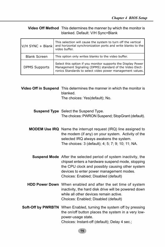
Chapter 4 BIOS Setup
75
Video Off Method This determines the manner by which the monitor isblanked. Default: V/H Sync+Blank
V/H SYNC + Blank
DPMS Supports
Blank Screen
This selection will cause the system to turn off the verticaland horizontal synchronization ports and write blanks to thevideo buffer.
This option only writes blanks to the video buffer.
Select this option if you monitor supports the Display PowerManagement Signaling (DPMS) standard of the Video Elect-ronics Standards to select video power management values.
MODEM Use IRQ Name the interrupt request (IRQ) line assigned tothe modem (if any) on your system. Activity of theselected IRQ always awakens the system.The choices: 3 (default); 4; 5; 7; 9; 10; 11; NA.
Soft-Off by PWRBTN When Enabled, turning the system off by pressingthe on/off button places the system in a very low-power-usage state.Choices: Instant-off (default); Delay 4 sec.;
Suspend Mode After the selected period of system inactivity, thechipset enters a hardware suspend mode, stoppingthe CPU clock and possibly causing other systemdevices to enter power management modes.Choices: Enabled; Disabled (default)
Video Off in Suspend This determines the manner in which the monitor isblanked.The choices: Yes(default); No.
Suspend Type Select the Suspend Type.The choices: PWRON Suspend; StopGrant (default).
HDD Power Down When enabled and after the set time of systeminactivity, the hard disk drive will be powered downwhile all other devices remain active.Choices: Enabled; Disabled (default)
Series SL-85SD
76
Power On by Ring An input signal on the serial Ring Indicator (RI) line(in other words, an incoming call on the modem)awakens the system from a soft off state.The choice: Enabled; Disabled (default).
USB KB Wake-UpFrom S3
This item will enable you to Wake-up the system byUSB keyboard when you shut down the computerin S3 Mode.The choices: Enabled; Disabled (default).
Wake-up by PCI card This function allows you to enabled the system bywake-up by PCI card.The choices: Enabled(default); Disabled.
Resume by Alarm When Enabled, you can set the data and time at thewhich the RTC (Real Time Clock) alarm awakensthe system from suspend mode. default: Disabled
Date (of Month) Alarm Set a certain date when RTC Alarm Resume optionis Enabled to awaken the system. This option isconcurrent with Resume Time option.
Time (hh:mm:ss) Set a certain time when RTC Alarm Resume optionis Enabled to awaken the system. This option isconcurrent with Date option.
CPU Thrm-Throttling This field sets the percent of CPU temperaturechange to display.The choices: 87.5%; 75.0%; 62.5%; 50.0%(default);37.5%; 25.0%;12.5%.

Chapter 4 BIOS Setup
77
Reload Global TimerEvents
Reload Global Timer Events are I/O events whoseoccurrence can prevent the system from entering apower saving mode or can awaken the system fromsuch a mode. In effect, the system remains alert foranything which occurs to a device which is configured asEnabled, even when the system is in a power downmode.
Primary IDE 0
Primary IDE 1
Secondary IDE 0
Secondary IDE 1
FDD, COM, LPT Port
PCI PIPQ[A-D]Default: All disabled
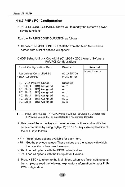
Series SL-85SD
78
• PNP/PCI CONFIGURATION allows you to modify the system’s power saving functions.
Run the PNP/PCI CONFIGURATION as follows:
1. Choose “PNP/PCI CONFIGURATION” from the Main Menu and ascreen with a list of options will appear:
4-6.7 PNP / PCI Configuration
Reset Configuration Data
Resources Controlled ByIRQ Resources
PCI/VGA Palette SnoopPCI Slot1 IRQ AssignedPCI Slot2 IRQ AssignedPCI Slot3 IRQ AssignedPCI Slot4 IRQ AssignedPCI Slot5 IRQ AssignedPCI Slot6 IRQ Assigned
Item Help
Menu Level
:Move Enter:Select +/-/PU/PD:Value F10:Save ESC:Exit F1:General HelpF5:Previous Values F6:Fail-Safe Defaults F7:Optimized Defaults
CMOS Setup Utility - Copyright (C) 1984 - 2001 Award SoftwarePnP/PCI Configurations
Disabled
Auto(ESCD)Press Enter
DisabledAutoAutoAutoAutoAutoAuto
3. Press <ESC> to return to the Main Menu when you finish setting up allitems. please read the following explanatory information for your PnP/PCI configuration.
2. Use one of the arrow keys to move between options and modify theselected options by using PgUp / PgDn / + / - keys. An explanation ofthe <F> keys follows:
<F1>: “Help” gives options available for each item.<F5>: Get the previous values. These values are the values with which
the user starts the current session.<F6>: Load all options with the BIOS default values.<F7>: Load all options with the Setup default values.
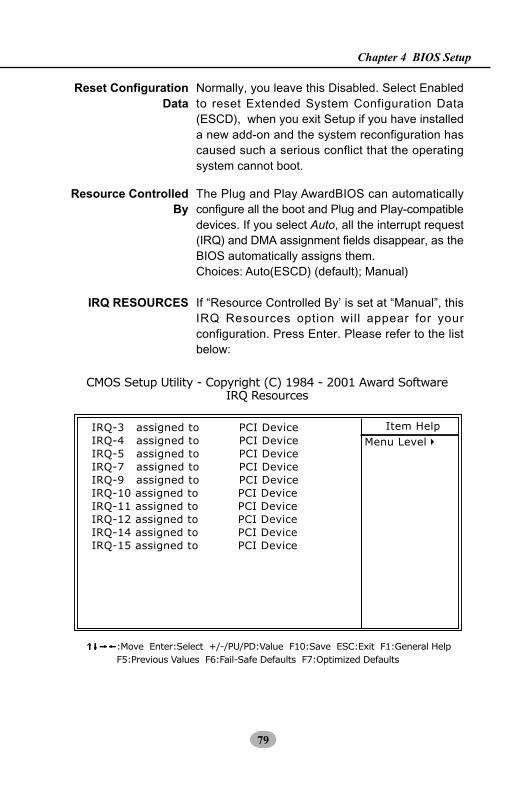
Chapter 4 BIOS Setup
79
IRQ-3 assigned to PCI DeviceIRQ-4 assigned to PCI DeviceIRQ-5 assigned to PCI DeviceIRQ-7 assigned to PCI DeviceIRQ-9 assigned to PCI DeviceIRQ-10 assigned to PCI DeviceIRQ-11 assigned to PCI DeviceIRQ-12 assigned to PCI DeviceIRQ-14 assigned to PCI DeviceIRQ-15 assigned to PCI Device
Item HelpMenu Level
:Move Enter:Select +/-/PU/PD:Value F10:Save ESC:Exit F1:General HelpF5:Previous Values F6:Fail-Safe Defaults F7:Optimized Defaults
CMOS Setup Utility - Copyright (C) 1984 - 2001 Award SoftwareIRQ Resources
Reset ConfigurationData
Normally, you leave this Disabled. Select Enabledto reset Extended System Configuration Data(ESCD), when you exit Setup if you have installeda new add-on and the system reconfiguration hascaused such a serious conflict that the operatingsystem cannot boot.
IRQ RESOURCES If “Resource Controlled By’ is set at “Manual”, thisIRQ Resources option will appear for yourconfiguration. Press Enter. Please refer to the listbelow:
Resource ControlledBy
The Plug and Play AwardBIOS can automaticallyconfigure all the boot and Plug and Play-compatibledevices. If you select Auto, all the interrupt request(IRQ) and DMA assignment fields disappear, as theBIOS automatically assigns them.Choices: Auto(ESCD) (default); Manual)

Series SL-85SD
80
PCI/VGA Palette Snoop This option allows the BIOS to preview VGA status,and to modify the information delivered from thefeature Connector of the VGA card to MPEG card.This option can solve the display inversion to blackafter you have used MPEG card.Choices: Disabled (default); Enabled
PCI Slot1~6 IRQAssigned to
Set to Auto, this option allows the BIOS to assignIRQ to PCI slot.Choices: Auto (default); 3; 4; 5; 6; 7; 8; 9; 10; 11; 12;14; 15.
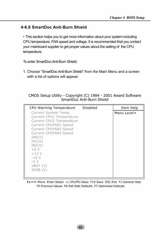
Chapter 4 BIOS Setup
81
• This section helps you to get more information about your system includingCPU temperature, FAN speed and voltage. It is recommended that you contactyour mainboard supplier to get proper values about the setting of the CPUtemperature.
To enter SmartDoc Anti-Burn Shield:
1. Choose “SmartDoc Anti-Burn Shield” from the Main Menu and a screenwith a list of options will appear:
4-6.8 SmartDoc Anti-Burn Shield
Item Help
Menu Level
CPU Warning Temperature Disabled
:Move Enter:Select +/-/PU/PD:Value F10:Save ESC:Exit F1:General HelpF5:Previous Values F6:Fail-Safe Defaults F7:Optimized Defaults
CMOS Setup Utility - Copyright (C) 1984 - 2001 Award SoftwareSmartDoc Anti-Burn Shield
Current System Temp. Current CPU1 Temperature Current CPU2 Temperature Current CPUFAN1 Speed Current CPUFAN2 Speed Current CPUFAN3 Speed IN0(V) IN1(V) IN2(V) +5 V +12 V -12 V -5 V VBAT (V) 5VSB (V)
Series SL-85SD
82
3. Press <ESC> to return to the Main Menu when you finish setting up all items. please read the following explanatory information for your SmartDoc Anti-Burn Shield Configuration:
CPU Warning Tem-perature
This field allows you to select a CPU Warning tem-perature against the CPU over heat. If the CPU tem-perature reaches “CPU warning temperature” thatyou select in this field, the BIOS will send out a warn-ing message.
Current System Temp. Showing the working System temperature.
2. Use one of the arrow keys to move between options and modify theselected options by using PgUp / PgDn / + / - keys.
<F1>: “Help” gives options available for each item.<F5>: Get the previous values. These values are the values with which
the user starts the current session.<F6>: Load all options with the BIOS default values.<F7>: Load all options with the Setup default values.
Current CPU1/2 Temp. Showing the working CPU temperature.
CPUFAN1/2 Speed Showing the working CPU Fan speed.
IN0/1/2, +5V/+12V/-12V/-5V
Showing the working voltage on board.
VBAT Showing the working battery voltage on board.
5VSB Showing the working standby voltage on board.
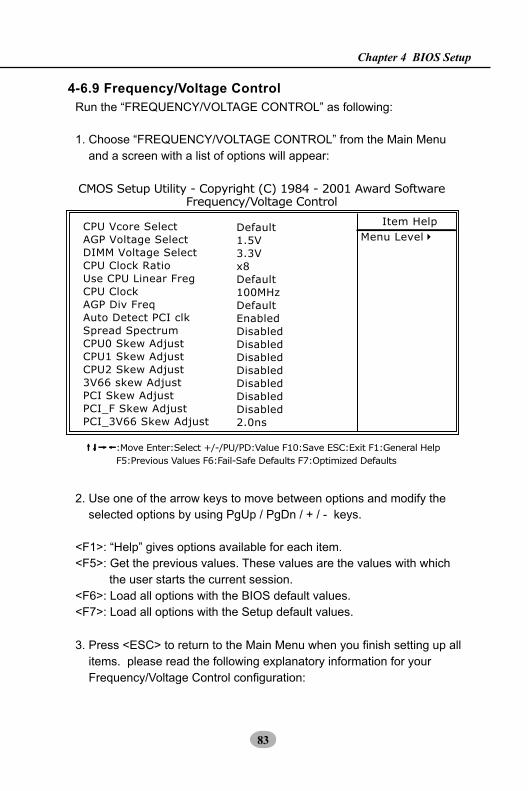
Chapter 4 BIOS Setup
83
Run the “FREQUENCY/VOLTAGE CONTROL” as following:
1. Choose “FREQUENCY/VOLTAGE CONTROL” from the Main Menuand a screen with a list of options will appear:
4-6.9 Frequency/Voltage Control
Item HelpMenu Level
:Move Enter:Select +/-/PU/PD:Value F10:Save ESC:Exit F1:General HelpF5:Previous Values F6:Fail-Safe Defaults F7:Optimized Defaults
CMOS Setup Utility - Copyright (C) 1984 - 2001 Award SoftwareFrequency/Voltage Control
CPU Vcore SelectAGP Voltage SelectDIMM Voltage SelectCPU Clock RatioUse CPU Linear FregCPU ClockAGP Div FreqAuto Detect PCI clkSpread SpectrumCPU0 Skew AdjustCPU1 Skew AdjustCPU2 Skew Adjust3V66 skew AdjustPCI Skew AdjustPCI_F Skew AdjustPCI_3V66 Skew Adjust
Default1.5V3.3Vx8Default100MHzDefaultEnabledDisabledDisabledDisabledDisabledDisabledDisabledDisabled2.0ns
2. Use one of the arrow keys to move between options and modify theselected options by using PgUp / PgDn / + / - keys.
<F1>: “Help” gives options available for each item.<F5>: Get the previous values. These values are the values with which
the user starts the current session.<F6>: Load all options with the BIOS default values.<F7>: Load all options with the Setup default values.
3. Press <ESC> to return to the Main Menu when you finish setting up all items. please read the following explanatory information for your Frequency/Voltage Control configuration:
Series SL-85SD
84
Auto Detect PCICLK
To reduce the occurrence of electromagneticinterference (EMI), the BIOS detects the presenceor absence of components in PCI slots and turns offsystem clock generator pulses against empty slots.hoices: Enabled (default); Disabled.
CPU VcoreSelect
This item allows you to adjust CPU Vcore. Yet, sincethe CPU Vcore can be auto-detected by CPU, youshould leave this item at default value unless youcan afford the risk of damaging your CPU.The choices: Default (Vcore auto-detected by CPU);1.100V~1.850V by 0.025 stepping).
CPU ClockRatio
This item allows you to select the CPU clock ratioso as to change or overclock the CPU frequency.However, if CPU clock Ratio is locked, this functionis invalid.
Use CPU LinearFrequency
This item allows you to adjust the CPU clock by1MHz stepping. Default CPU clock is 100MHz. Anyoverclocking is taking the risk of unstabilizing theCPU and system performance.Choices: Default; Use linear (1MHz stepping).
CPU Clock If “Use CPU Linear Frequency” is set at “Use linear”,you can adjust the CPU clock by 1MHz stepping upor down.Choices: 1MHz stepping.
AGP Div Freq. This item allows you to adjust the AGP Frequencyby fraction of your CPU Host clock. Default AGPfrequency is 66MHz. The choices (fraction of CPUclock): Default; 2/2; 2/3; 2/4; 2/5; 2/6; 2/7; 2/8.
DIMM VoltageSelect
This item allows user to adjust DIMM voltage by0.1V stepping.Choices: 3.3V (Default); 3.4V; 3.5V; 3.6V.
AGP VoltageSelect
This item allows user to adjust AGP voltage by0.1V stepping.Choices: 1.5V (Default); 1.6V; 1.7V.
Chapter 4 BIOS Setup
85
CPU0/1/2 SkewAdjust
This item allows you to reduce CPU transfer rate.Users should leave this item at default value.The choices: Disabled (default); 500ps; 1000ps;1500ps.
PCI Skew Adjust This item allows you to reduce PCI transfer rate.Users should leave this item at default value.Choices: Disabled (default); 500ps; 1000ps; 1500ps.
3V66 SkewAdjust
This item allows you to reduce the 3V66 transferrate.Choices: Disabled (default); 500ps; 1000ps; 1500ps.
PCI_F SkewAdjust
This item allows you to reduce PCI transfer rate.Users should leave this item at default value.Choices: Disabled (default); 500ps; 1000ps; 1500ps.
PCI_3V66 SkewAdjust
This item allows you to reduce PCI transfer rate.Choices: 2.0ns (default); 3.0ns.
Spread Spec-trum
When the system clock generator pulses, theextreme values of the pulse generate excess EMI.Enabling pulse spectrum spread modulationchanges the extreme values from spikes to flatcurves, thus reducing EMI. This benefit may in somecases be outweighed by problems with timing-criticaldevices, such as a clock-sensitive SCSI device.Choices: Disabled (default); enabled.
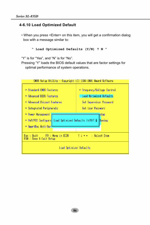
Series SL-85SD
86
• When you press <Enter> on this item, you will get a confirmation dialog box with a message similar to:
“ Load Optimized Defaults (Y/N) ? N ”
“Y” is for “Yes”, and “N” is for “No”.Pressing “Y” loads the BIOS default values that are factor settings for
optimal performance of system operations.
4-6.10 Load Optimized Default
Chapter 4 BIOS Setup
87
4-6.11 Set Supervisor / User Password
• These two options allow you to set your system passwords. Normally, the supervisor has a higher priority to change the CMOS setup option than the users. The way to set up the passwords for both Supervisor and Users are as follows:
1. Choose “Change Password” in the Main Menu and press <Enter>.Then following message appears:
“Enter Password : “
2. The first time you run this option, enter your password up to 8 charac-ters and press <Enter>. (The screen does not display the enteredcharacters.)
3. After you enter the password, the following message appears prompt-ing you to confirm the password:
“Confirm Password : “
4. Enter the same password “exactly” the same as you have just typed toconfirm the password and press <Enter>.
5. Move the cursor to Save & Exit Setup to save the password.6. If you need to delete the password entered before, choose the Supervi-
sor Password and press <Enter>. It will delete the password that youhave entered before.
7. Move the cursor to Save & Exit Setup to save the option you have just configured; otherwise the old password will still be there the next time
you turn your system on.8. Press <Enter> to exit to the Main Menu.
NOTE: If you forget or lose the password, the only way to access the
system is to clear the CMOS RAM. All setup informations will be lost and
you need to run the BIOS setup program again.
Series SL-85SD
88
4-6.12 Save & Exit Setup
• SAVE & EXIT SETUP allows you to save all modifications you have specified into the CMOS memory. Highlight this option on the MainMenu and the following message appears:
“ SAVE to CMOS and EXIT (Y/N) ? Y “
“Y” is for “Yes”, and “N” is for “No”.Press <Enter> key to save the configuration changes.
4-6.13 Exit Without Saving
• EXIT WITHOUT SAVING option allows you to exit the Setup Utility without saving the modifications that you have specified. Highlight this option on the Main Menu and the following message appears:
“ Quit Without Saving (Y/N) ? N “
“Y” is for “Yes”, and “N” is for “No”.You may change the prompt to “Y” and press <Enter> key to leave thisoption .

Chapter 4 BIOS Setup
89
MEMOMEMO
Series SL-85SD
90
Chapter 5 RAID Controller
5-0 Before Creating Disk Array5-1 Creating your Disk Array5-2 Using FASTBUILDTM Configuration Utility5-3 Installing FAST TRAK100-LITE Driver
The following topics and Appendices are included inthis chapter:
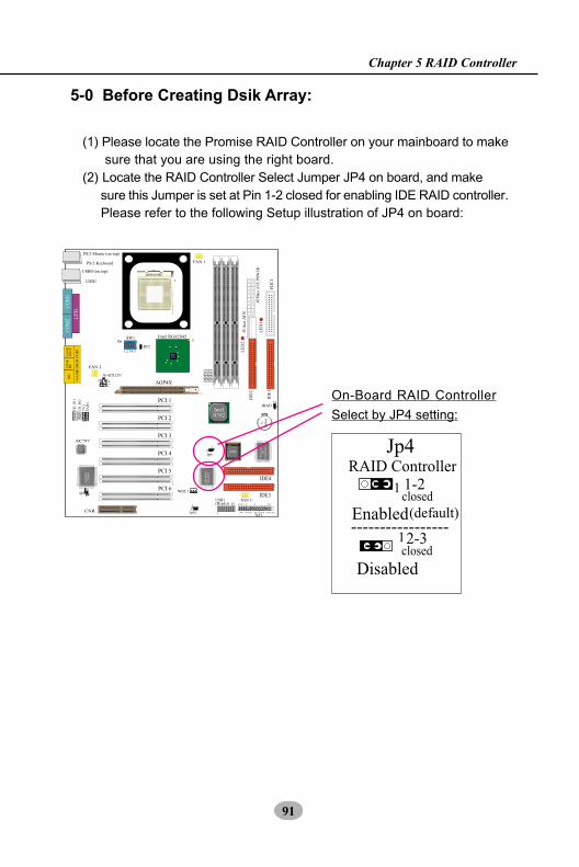
Chapter 5 RAID Controller
91
PCI 1
PCI 2
PCI 3
PCI 4
PCI 5
PCI 6
CNR
Cre
ativ
e�C
T58
80
IDE
RA
ID�
cont
rolle
r
IDE4
IDE3
1
1
SPK S3/LED KEYLOCK SUS/LED
HDD/LED IR SMI+ +- -
+ -1 15
Li�
Bat
tery
FWH
W
inbo
nd
�
I/O
�
Con
trol
ler
DIM
M1�
DIM
M2�
DIM
M3
IDE
1
IDE
2
FDC
1
J4 M
ain
AT
X P
OW
ER
USB1�(Header)
1
16
GA
ME
/MID
I P
OR
T
LIN
E�
OU
TL
INE
�IN
LPT1
CO
M1
CO
M2
Intel�ICH2
1
1
1
1
ON DIP
SW1
WOL1
CD
_IN
1
CD
_IN
2
MIC
1
FAN 1
FAN 2
FAN 3
Jp10
Jp4
Jp5
TV
1TA
D1
J6 ATX12V
1 23 4
1
PS/2 Mouse (on top)
PS/2 Keyboard
USB0 (on top)
USB1
J5 A
ux A
TX
1
�
mPGA478B
2 34 5
Intel RG82845
Intel RG82845
AGP4X
RT2
1JBAT1
AC'97Codec
AC'97
On
30
NJ1
LE
D2
LE
D1
5-0 Before Creating Dsik Array:
(1) Please locate the Promise RAID Controller on your mainboard to make sure that you are using the right board.(2) Locate the RAID Controller Select Jumper JP4 on board, and make sure this Jumper is set at Pin 1-2 closed for enabling IDE RAID controller. Please refer to the following Setup illustration of JP4 on board:
On-Board RAID Controller
Select by JP4 setting:
1
1
Jp4
2-3 closed
1-2closed
RAID Controller
Enabled
Disabled
-----------------(default)
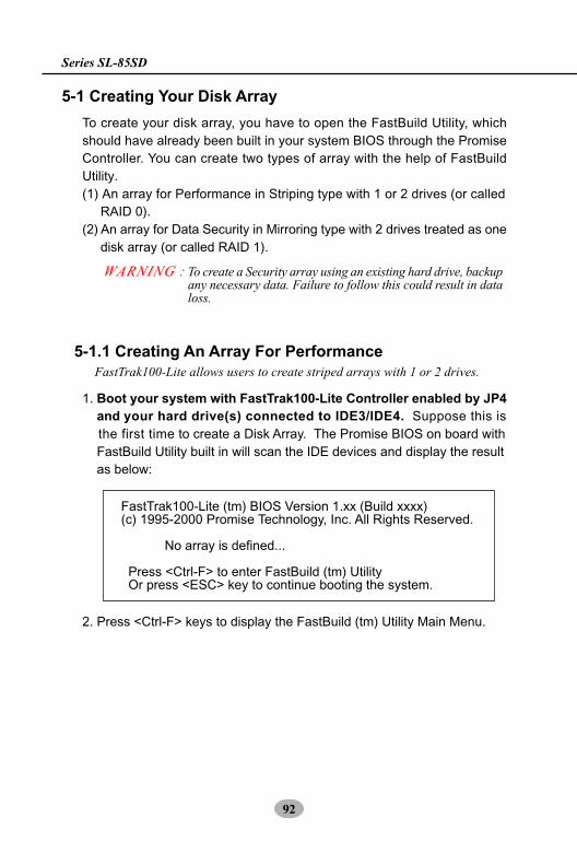
Series SL-85SD
92
5-1.1 Creating An Array For PerformanceFastTrak100-Lite allows users to create striped arrays with 1 or 2 drives.
To create your disk array, you have to open the FastBuild Utility, whichshould have already been built in your system BIOS through the PromiseController. You can create two types of array with the help of FastBuildUtility.(1) An array for Performance in Striping type with 1 or 2 drives (or called RAID 0).(2) An array for Data Security in Mirroring type with 2 drives treated as one disk array (or called RAID 1).
2. Press <Ctrl-F> keys to display the FastBuild (tm) Utility Main Menu.
5-1 Creating Your Disk Array
1. Boot your system with FastTrak100-Lite Controller enabled by JP4 and your hard drive(s) connected to IDE3/IDE4. Suppose this is the first time to create a Disk Array. The Promise BIOS on board with FastBuild Utility built in will scan the IDE devices and display the result as below:
WARNING :WARNING : To create a Security array using an existing hard drive, backup any necessary data. Failure to follow this could result in data loss.
FastTrak100-Lite (tm) BIOS Version 1.xx (Build xxxx) (c) 1995-2000 Promise Technology, Inc. All Rights Reserved.
No array is defined...
Press <Ctrl-F> to enter FastBuild (tm) Utility Or press <ESC> key to continue booting the system.
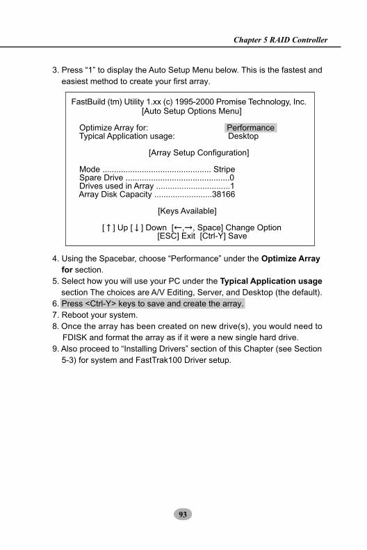
Chapter 5 RAID Controller
93
4. Using the Spacebar, choose “Performance” under the Optimize Array for section.5. Select how you will use your PC under the Typical Application usage section The choices are A/V Editing, Server, and Desktop (the default).6. Press <Ctrl-Y> keys to save and create the array.7. Reboot your system.8. Once the array has been created on new drive(s), you would need to FDISK and format the array as if it were a new single hard drive.9. Also proceed to “Installing Drivers” section of this Chapter (see Section 5-3) for system and FastTrak100 Driver setup.
3. Press “1” to display the Auto Setup Menu below. This is the fastest and easiest method to create your first array.
FastBuild (tm) Utility 1.xx (c) 1995-2000 Promise Technology, Inc. [Auto Setup Options Menu]
Optimize Array for: Performance Typical Application usage: Desktop
[Array Setup Configuration]
Mode ............................................... Stripe Spare Drive .............................................0 Drives used in Array ................................1 Array Disk Capacity .........................38166
[Keys Available]
[�] Up [�] Down [�,�, Space] Change Option [ESC] Exit [Ctrl-Y] Save
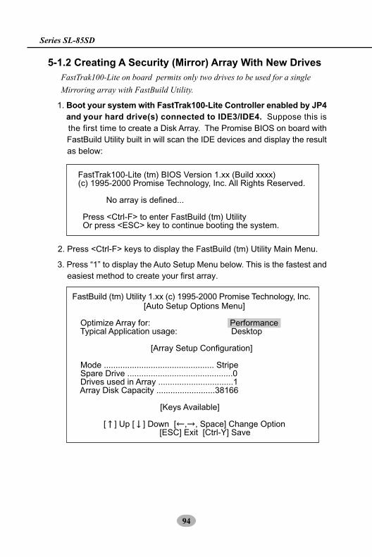
Series SL-85SD
94
5-1.2 Creating A Security (Mirror) Array With New DrivesFastTrak100-Lite on board permits only two drives to be used for a single
Mirroring array with FastBuild Utility.
2. Press <Ctrl-F> keys to display the FastBuild (tm) Utility Main Menu.
1. Boot your system with FastTrak100-Lite Controller enabled by JP4 and your hard drive(s) connected to IDE3/IDE4. Suppose this is the first time to create a Disk Array. The Promise BIOS on board with FastBuild Utility built in will scan the IDE devices and display the result as below:
FastTrak100-Lite (tm) BIOS Version 1.xx (Build xxxx) (c) 1995-2000 Promise Technology, Inc. All Rights Reserved.
No array is defined...
Press <Ctrl-F> to enter FastBuild (tm) Utility Or press <ESC> key to continue booting the system.
3. Press “1” to display the Auto Setup Menu below. This is the fastest and easiest method to create your first array.
FastBuild (tm) Utility 1.xx (c) 1995-2000 Promise Technology, Inc. [Auto Setup Options Menu]
Optimize Array for: Performance Typical Application usage: Desktop
[Array Setup Configuration]
Mode ............................................... Stripe Spare Drive .............................................0 Drives used in Array ................................1 Array Disk Capacity .........................38166
[Keys Available]
[�] Up [�] Down [�,�, Space] Change Option [ESC] Exit [Ctrl-Y] Save
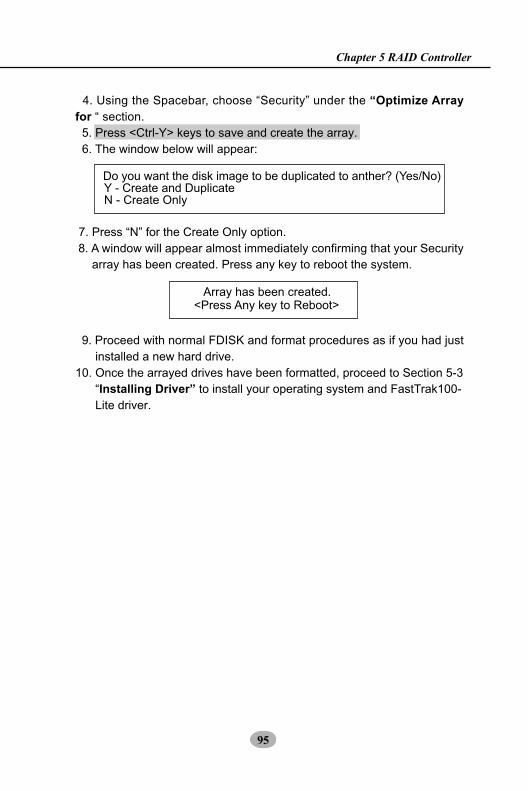
Chapter 5 RAID Controller
95
4. Using the Spacebar, choose “Security” under the “Optimize Arrayfor “ section. 5. Press <Ctrl-Y> keys to save and create the array. 6. The window below will appear:
7. Press “N” for the Create Only option. 8. A window will appear almost immediately confirming that your Security array has been created. Press any key to reboot the system.
Array has been created. <Press Any key to Reboot>
Do you want the disk image to be duplicated to anther? (Yes/No) Y - Create and Duplicate N - Create Only
9. Proceed with normal FDISK and format procedures as if you had just installed a new hard drive.10. Once the arrayed drives have been formatted, proceed to Section 5-3 “Installing Driver” to install your operating system and FastTrak100- Lite driver.
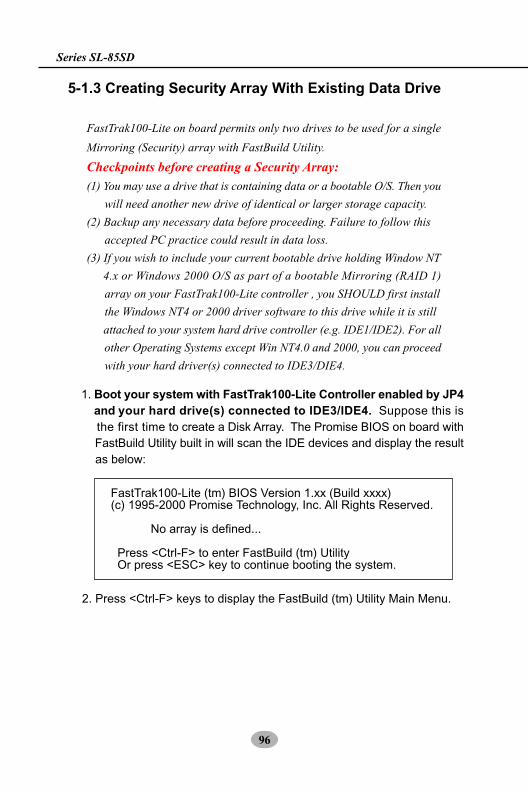
Series SL-85SD
96
5-1.3 Creating Security Array With Existing Data Drive
FastTrak100-Lite on board permits only two drives to be used for a single
Mirroring (Security) array with FastBuild Utility.
Checkpoints before creating a Security Array:(1) You may use a drive that is containing data or a bootable O/S. Then you
will need another new drive of identical or larger storage capacity.
(2) Backup any necessary data before proceeding. Failure to follow this
accepted PC practice could result in data loss.
(3) If you wish to include your current bootable drive holding Window NT
4.x or Windows 2000 O/S as part of a bootable Mirroring (RAID 1)
array on your FastTrak100-Lite controller , you SHOULD first install
the Windows NT4 or 2000 driver software to this drive while it is still
attached to your system hard drive controller (e.g. IDE1/IDE2). For all
other Operating Systems except Win NT4.0 and 2000, you can proceed
with your hard driver(s) connected to IDE3/DIE4.
2. Press <Ctrl-F> keys to display the FastBuild (tm) Utility Main Menu.
1. Boot your system with FastTrak100-Lite Controller enabled by JP4 and your hard drive(s) connected to IDE3/IDE4. Suppose this is the first time to create a Disk Array. The Promise BIOS on board with FastBuild Utility built in will scan the IDE devices and display the result as below:
FastTrak100-Lite (tm) BIOS Version 1.xx (Build xxxx) (c) 1995-2000 Promise Technology, Inc. All Rights Reserved.
No array is defined...
Press <Ctrl-F> to enter FastBuild (tm) Utility Or press <ESC> key to continue booting the system.
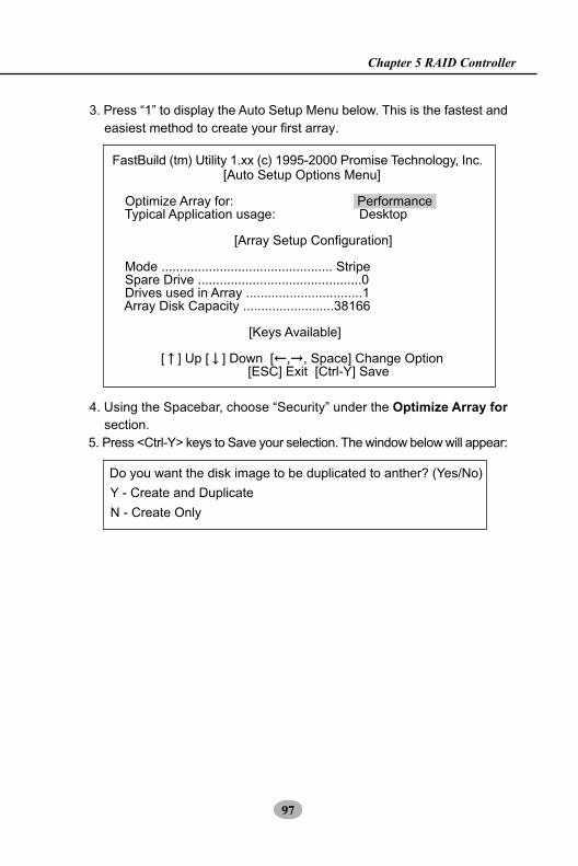
Chapter 5 RAID Controller
97
4. Using the Spacebar, choose “Security” under the Optimize Array for section. 5. Press <Ctrl-Y> keys to Save your selection. The window below will appear:
Do you want the disk image to be duplicated to anther? (Yes/No)
Y - Create and Duplicate
N - Create Only
3. Press “1” to display the Auto Setup Menu below. This is the fastest and easiest method to create your first array.
FastBuild (tm) Utility 1.xx (c) 1995-2000 Promise Technology, Inc. [Auto Setup Options Menu]
Optimize Array for: Performance Typical Application usage: Desktop
[Array Setup Configuration]
Mode ............................................... Stripe Spare Drive .............................................0 Drives used in Array ................................1 Array Disk Capacity .........................38166
[Keys Available]
[�] Up [�] Down [�,�, Space] Change Option [ESC] Exit [Ctrl-Y] Save
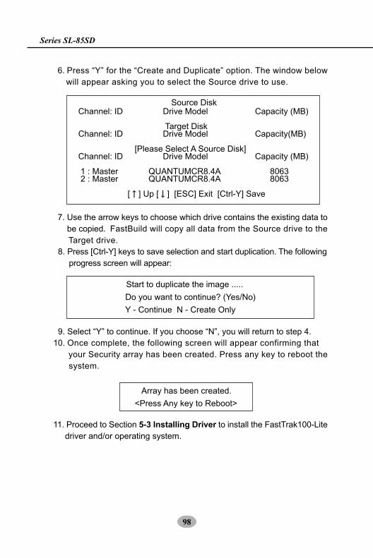
Series SL-85SD
98
Array has been created.
<Press Any key to Reboot>
11. Proceed to Section 5-3 Installing Driver to install the FastTrak100-Lite driver and/or operating system.
Source Disk Channel: ID Drive Model Capacity (MB)
Target Disk Channel: ID Drive Model Capacity(MB)
[Please Select A Source Disk] Channel: ID Drive Model Capacity (MB)
1 : Master QUANTUMCR8.4A 8063 2 : Master QUANTUMCR8.4A 8063
[�] Up [�] [ESC] Exit [Ctrl-Y] Save
9. Select “Y” to continue. If you choose “N”, you will return to step 4.10. Once complete, the following screen will appear confirming that your Security array has been created. Press any key to reboot the system.
6. Press “Y” for the “Create and Duplicate” option. The window below will appear asking you to select the Source drive to use.
7. Use the arrow keys to choose which drive contains the existing data to be copied. FastBuild will copy all data from the Source drive to the Target drive. 8. Press [Ctrl-Y] keys to save selection and start duplication. The following progress screen will appear:
Start to duplicate the image .....
Do you want to continue? (Yes/No)
Y - Continue N - Create Only
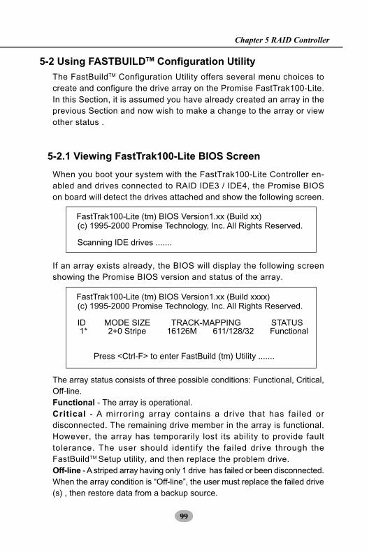
Chapter 5 RAID Controller
99
If an array exists already, the BIOS will display the following screenshowing the Promise BIOS version and status of the array.
The FastBuildTM Configuration Utility offers several menu choices tocreate and configure the drive array on the Promise FastTrak100-Lite.In this Section, it is assumed you have already created an array in theprevious Section and now wish to make a change to the array or viewother status .
5-2 Using FASTBUILDTM Configuration Utility
When you boot your system with the FastTrak100-Lite Controller en-abled and drives connected to RAID IDE3 / IDE4, the Promise BIOSon board will detect the drives attached and show the following screen.
The array status consists of three possible conditions: Functional, Critical,Off-line.Functional - The array is operational.Critical - A mirroring array contains a drive that has failed ordisconnected. The remaining drive member in the array is functional.However, the array has temporarily lost its ability to provide faulttolerance. The user should identify the failed drive through theFastBuildTM Setup utility, and then replace the problem drive.Off-line - A striped array having only 1 drive has failed or been disconnected.When the array condition is “Off-line”, the user must replace the failed drive(s) , then restore data from a backup source.
FastTrak100-Lite (tm) BIOS Version1.xx (Build xx) (c) 1995-2000 Promise Technology, Inc. All Rights Reserved.
Scanning IDE drives .......
FastTrak100-Lite (tm) BIOS Version1.xx (Build xxxx) (c) 1995-2000 Promise Technology, Inc. All Rights Reserved.
ID MODE SIZE TRACK-MAPPING STATUS 1* 2+0 Stripe 16126M 611/128/32 Functional
Press <Ctrl-F> to enter FastBuild (tm) Utility .......
5-2.1 Viewing FastTrak100-Lite BIOS Screen
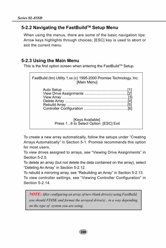
Series SL-85SD
100
To create a new array automatically, follow the setups under “CreatingArrays Automatically” in Section 5-1. Promise recommends this optionfor most users.To view drives assigned to arrays, see “Viewing Drive Assignments” inSection 5-2.5.To delete an array (but not delete the data contained on the array), select“Deleting An Array” in Section 5-2.12.To rebuild a mirroring array, see “Rebuilding an Array” in Section 5-2.13.To view controller settings, see “Viewing Controller Configuration” inSection 5-2.14.
When using the menus, there are some of the basic navigation tips:Arrow keys highlights through choices; [ESC] key is used to abort orexit the current menu.
5-2.3 Using the Main MenuThis is the first option screen when entering the FastBuildTM Setup.
5-2.2 Navigating the FastBuildTM Setup Menu
FastBuild (tm) Utility 1.xx (c) 1995-2000 Promise Technology, Inc. [Main Menu]
Auto Setup ..............................................................[1] View Drive Assignments .........................................[2] View Array ...............................................................[3] Delete Array ............................................................[4] Rebuild Array ..........................................................[5] Controller Configuration ..........................................[6]
[Keys Available] Press 1...6 to Select Option [ESC] Exit
NOTE: After configuring an array of new blank drive(s) using FastBuild,
you should FDISK and format the arrayed drive(s) , in a way depending
on the type of system you are using.
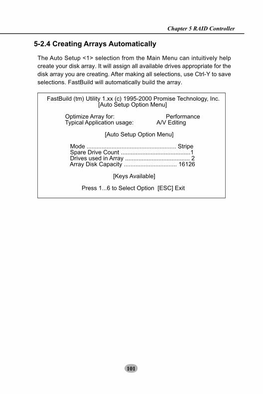
Chapter 5 RAID Controller
101
The Auto Setup <1> selection from the Main Menu can intuitively helpcreate your disk array. It will assign all available drives appropriate for thedisk array you are creating. After making all selections, use Ctrl-Y to saveselections. FastBuild will automatically build the array.
FastBuild (tm) Utility 1.xx (c) 1995-2000 Promise Technology, Inc. [Auto Setup Option Menu]
Optimize Array for: Performance Typical Application usage: A/V Editing
[Auto Setup Option Menu]
Mode ...................................................... Stripe Spare Drive Count ..........................................1 Drives used in Array ....................................... 2 Array Disk Capacity ................................ 16126
[Keys Available]
Press 1...6 to Select Option [ESC] Exit
5-2.4 Creating Arrays Automatically
Series SL-85SD
102
Allows the user to choose the type of PC usage that will be performed inorder to optimize how FastTrak100-Lite handles data blocks to enhanceperformance. Your choice will determine the block size used. You maychoose from: A/V Editing (for audio/video applications, or any similar appli-cation that requires large file transfers), Server (for numbers of small filetransfers), or Desktop (a combination of large and small file sizes).
(2) Security (RAID 1 Mirroring)Creates a mirrored (or fault tolerant) array for data security.
NOTE: Under the Security setting, FastTrak100-Lite permits two drives
to be used for a single Mirrored array.
NOTE: FastTrak100-Lite permits striped arrays of 1 or 2 drives attached
in Auto Setup mode.
5-2.4-2 Defining Typical Application Usage
5-2.4-1 Optimize Array For
Select whether you want Performance (RAID 0), or Security (RAID 1)
under the “Optimize Array for” setting.
(1) Performance (RAID 0 Striping)
Supports the maximum performance. The storage capacity equals the
number of drives times the capacity of the smallest drive in the disk array.
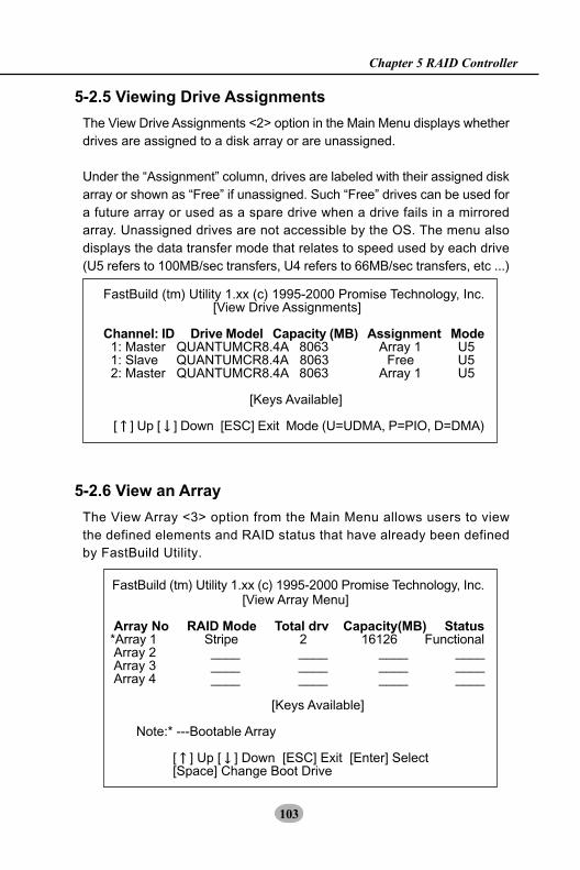
Chapter 5 RAID Controller
103
5-2.6 View an Array
FastBuild (tm) Utility 1.xx (c) 1995-2000 Promise Technology, Inc. [View Array Menu]
Array No RAID Mode Total drv Capacity(MB) Status *Array 1 Stripe 2 16126 Functional Array 2 ____ ____ ____ ____ Array 3 ____ ____ ____ ____ Array 4 ____ ____ ____ ____
[Keys Available]
Note:* ---Bootable Array
[�] Up [�] Down [ESC] Exit [Enter] Select [Space] Change Boot Drive
The View Drive Assignments <2> option in the Main Menu displays whetherdrives are assigned to a disk array or are unassigned.
Under the “Assignment” column, drives are labeled with their assigned diskarray or shown as “Free” if unassigned. Such “Free” drives can be used fora future array or used as a spare drive when a drive fails in a mirroredarray. Unassigned drives are not accessible by the OS. The menu alsodisplays the data transfer mode that relates to speed used by each drive(U5 refers to 100MB/sec transfers, U4 refers to 66MB/sec transfers, etc ...)
5-2.5 Viewing Drive Assignments
FastBuild (tm) Utility 1.xx (c) 1995-2000 Promise Technology, Inc. [View Drive Assignments]
Channel: ID Drive Model Capacity (MB) Assignment Mode 1: Master QUANTUMCR8.4A 8063 Array 1 U5 1: Slave QUANTUMCR8.4A 8063 Free U5 2: Master QUANTUMCR8.4A 8063 Array 1 U5
[Keys Available]
[�] Up [�] Down [ESC] Exit Mode (U=UDMA, P=PIO, D=DMA)
The View Array <3> option from the Main Menu allows users to viewthe defined elements and RAID status that have already been definedby FastBuild Utility.
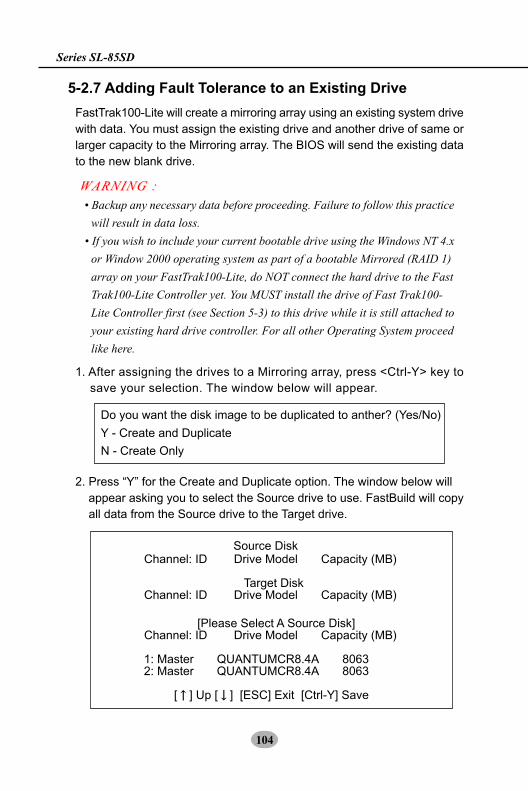
Series SL-85SD
104
2. Press “Y” for the Create and Duplicate option. The window below will appear asking you to select the Source drive to use. FastBuild will copy all data from the Source drive to the Target drive.
5-2.7 Adding Fault Tolerance to an Existing Drive
FastTrak100-Lite will create a mirroring array using an existing system drivewith data. You must assign the existing drive and another drive of same orlarger capacity to the Mirroring array. The BIOS will send the existing datato the new blank drive.
1. After assigning the drives to a Mirroring array, press <Ctrl-Y> key to save your selection. The window below will appear.
Source Disk Channel: ID Drive Model Capacity (MB)
Target Disk Channel: ID Drive Model Capacity (MB)
[Please Select A Source Disk] Channel: ID Drive Model Capacity (MB)
1: Master QUANTUMCR8.4A 8063 2: Master QUANTUMCR8.4A 8063
[�] Up [�] [ESC] Exit [Ctrl-Y] Save
Do you want the disk image to be duplicated to anther? (Yes/No)
Y - Create and Duplicate
N - Create Only
WARNING :WARNING :
• Backup any necessary data before proceeding. Failure to follow this practice
will result in data loss.
• If you wish to include your current bootable drive using the Windows NT 4.x
or Window 2000 operating system as part of a bootable Mirrored (RAID 1)
array on your FastTrak100-Lite, do NOT connect the hard drive to the Fast
Trak100-Lite Controller yet. You MUST install the drive of Fast Trak100-
Lite Controller first (see Section 5-3) to this drive while it is still attached to
your existing hard drive controller. For all other Operating System proceed
like here.
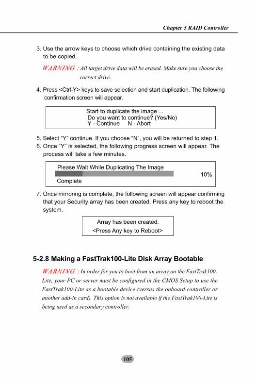
Chapter 5 RAID Controller
105
5. Select “Y” continue. If you choose “N”, you will be returned to step 1.6. Once “Y” is selected, the following progress screen will appear. The process will take a few minutes.
Array has been created.
<Press Any key to Reboot>
5-2.8 Making a FastTrak100-Lite Disk Array Bootable
3. Use the arrow keys to choose which drive containing the existing data to be copied.
4. Press <Ctrl-Y> keys to save selection and start duplication. The following confirmation screen will appear.
7. Once mirroring is complete, the following screen will appear confirming that your Security array has been created. Press any key to reboot the system.
Start to duplicate the image ... Do you want to continue? (Yes/No) Y - Continue N - Abort
Please Wait While Duplicating The Image 10% Complete
WARNING :WARNING : All target drive data will be erased. Make sure you choose the
correct drive.
WARNING :WARNING : In order for you to boot from an array on the FastTrak100-
Lite, your PC or server must be configured in the CMOS Setup to use the
FastTrak100-Lite as a bootable device (versus the onboard controller or
another add-in card). This option is not available if the FastTrak100-Lite is
being used as a secondary controller.
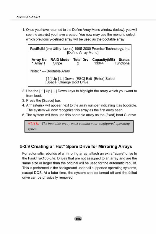
Series SL-85SD
106
1. Once you have returned to the Define Array Menu window (below), you will see the array(s) you have created. You now may use the menu to select which previously-defined array will be used as the bootable array.
5-2.9 Creating a “Hot” Spare Drive for Mirroring Arrays
2. Use the [�] Up [�] Down keys to highlight the array which you want to from boot.3. Press the [Space] bar.4. An* asterisk will appear next to the array number indicating it as bootable. The system will now recognize this array as the first array seen.5. The system will then use this bootable array as the (fixed) boot C: drive.
NOTE: The bootable array must contain your configured operating
system.
FastBuild (tm) Utility 1.xx (c) 1995-2000 Promise Technology, Inc. [Define Array Menu]
Array No RAID Mode Total Drv Capacity(MB) Status * Array 1 Stripe 2 13044 Functional
Note: * --- Bootable Array
[�] Up [�] Down [ESC] Exit [Enter] Select [Space] Change Boot Drive
For automatic rebuilds of a mirroring array, attach an extra “spare” drive tothe FaskTrak100-Lite. Drives that are not assigned to an array and are thesame size or larger than the original will be used for the automatic rebuild.This is performed in the background under all supported operating systems,except DOS. At a later time, the system can be turned off and the faileddrive can be physically removed.
Chapter 5 RAID Controller
107
All disk array data are saved into the reserved sector on each array member.Promise suggests that users record their disk array information for futurereference.
Another feature of the FastTrak100-Lite disk array system is to recognizedrive members event if drives are moved between different FastTrak100-Lite card connectors. Since each drive’s array data identifies itself to thearray, it is possible to move or swap drives without modifying the arraysetup. This is valuable when adding drives, or during a rebuild.
5-2.12 Deleting An Array
The Delete Array <4> Menu option allows for deletion of disk array
assignments. This is not the same as deleting data from the drivesthemselves. If you delete an array by accident (and before it be usedagain), the array can normally be recovered by defining the array iden-tically as deleted array (by Using Auto Setup).
5-2.10 How FastTrak100-Lite Orders Arrays
During startup, the disk arrays on the FastTrak100-Lite are recognized in
this order: 1) The array set to bootable in the FastBuildTM Setup, and 2) theArray number (i.e. Array 0, Array 1 ...). This would involve determiningwhich drive letters will be assigned to each disk array.
WARNING: Deleting an exiting disk array could result in its data loss.
Make sure to record all array information including the array type, the
disk members, and stripe block size in case you wish to undo a deletion.
5-2.11 How FastTrak100-Lite Saves Array Information
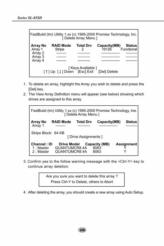
Series SL-85SD
108
3. Confirm yes to the follow warning message with the <Ctrl-Y> key to continue array deletion:
Are you sure you want to delete this array ?
Press Ctrl-Y to Delete, others to Abort
FastBuild (tm) Utility 1.xx (c) 1995-2000 Promise Technology, Ine. [ Delete Array Menu ]
Array No RAID Mode Total Drv Capacity(MB) Status Array 1 -------- ---------- --------------- ---------
Stripe Block: 64 KB [ Drive Assignments ]
Channel : ID Drive Model Capacity (MB) Assignment 1 : Master QUANTUMCR8.4A 8063 Y 2 : Master QUANTUMCR8.4A 8063 Y
4. After deleting the array, you should create a new array using Auto Setup.
1. To delete an array, highlight the Array you wish to delete and press the [Del] key.2. The View Array Definition menu will appear (see below) showing which drives are assigned to this array.
FastBuild (tm) Utility 1.xx (c) 1995-2000 Promise Technology, Inc. [ Delete Array Menu ]
Array No RAID Mode Total Drv Capacity(MB) Status Array 1 Stripe 2 16126 Functional Array 2 -------- ---------- --------------- --------- Array 3 -------- ---------- --------------- --------- Array 4 -------- ---------- --------------- ---------
[ Keys Available ] [�] Up [�] Down [Esc] Exit [Del] Delete
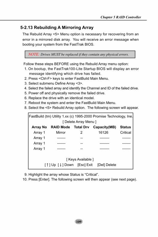
Chapter 5 RAID Controller
109
Follow these steps BEFORE using the Rebuild Array menu option: 1. On bootup, the FastTrak100-Lite Startup BIOS will display an error message identifying which drive has failed. 2. Press <Ctrl-F> keys to enter FastBuild Main Menu. 3. Select submenu Define Array <3>. 4. Select the failed array and identify the Channel and ID of the failed drive. 5. Power off and physically remove the failed drive. 6. Replace the drive with an identical model. 7. Reboot the system and enter the FastBuild Main Menu. 8. Select the <5> Rebuild Array option. The following screen will appear.
5-2.13 Rebuilding A Mirroring Array
The Rebuild Array <5> Menu option is necessary for recovering from an
error in a mirrored disk array. You will receive an error message whenbooting your system from the FastTrak BIOS.
NOTE: Drives MUST be replaced if they contain any physical errors.
9. Highlight the array whose Status is “Critical”.10. Press [Enter]. The following screen will then appear (see next page).
FastBuild (tm) Utility 1.xx (c) 1995-2000 Promise Technology, Ine.
[ Delete Array Menu ]
Array No RAID Mode Total Drv Capacity(MB) Status
Array 1 Mirror 2 16126 Critical
Array 1 ------- -- -------- -------
Array 1 ------- -- -------- -------
Array 1 ------- -- -------- -------
[ Keys Available ]
[�] Up [�] Down [Esc] Exit [Del] Delete
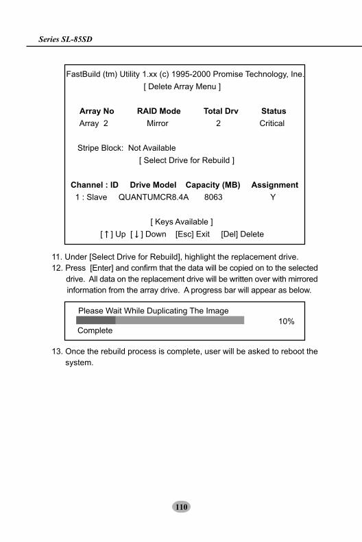
Series SL-85SD
110
13. Once the rebuild process is complete, user will be asked to reboot the system.
= Please Wait While Duplicating The Image 10% Complete
11. Under [Select Drive for Rebuild], highlight the replacement drive.12. Press [Enter] and confirm that the data will be copied on to the selected drive. All data on the replacement drive will be written over with mirrored information from the array drive. A progress bar will appear as below.
FastBuild (tm) Utility 1.xx (c) 1995-2000 Promise Technology, Ine.
[ Delete Array Menu ]
Array No RAID Mode Total Drv Status
Array 2 Mirror 2 Critical
Stripe Block: Not Available
[ Select Drive for Rebuild ]
Channel : ID Drive Model Capacity (MB) Assignment
1 : Slave QUANTUMCR8.4A 8063 Y
[ Keys Available ]
[�] Up [�] Down [Esc] Exit [Del] Delete
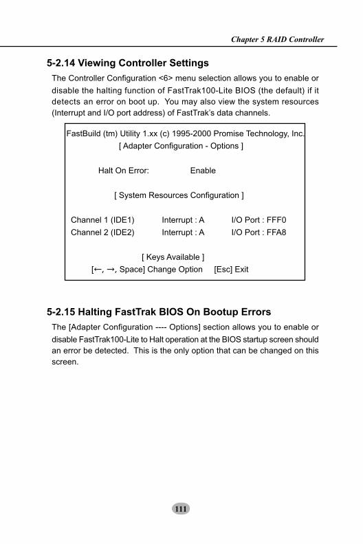
Chapter 5 RAID Controller
111
5-2.14 Viewing Controller Settings
The Controller Configuration <6> menu selection allows you to enable or
disable the halting function of FastTrak100-Lite BIOS (the default) if itdetects an error on boot up. You may also view the system resources(Interrupt and I/O port address) of FastTrak’s data channels.
5-2.15 Halting FastTrak BIOS On Bootup Errors
The [Adapter Configuration ---- Options] section allows you to enable or
disable FastTrak100-Lite to Halt operation at the BIOS startup screen shouldan error be detected. This is the only option that can be changed on thisscreen.
FastBuild (tm) Utility 1.xx (c) 1995-2000 Promise Technology, Inc.
[ Adapter Configuration - Options ]
Halt On Error: Enable
[ System Resources Configuration ]
Channel 1 (IDE1) Interrupt : A I/O Port : FFF0
Channel 2 (IDE2) Interrupt : A I/O Port : FFA8
[ Keys Available ]
[�I=�I=Space] Change Option [Esc] Exit
Series SL-85SD
112
5-3 Installing Drivers
This section details the FastTrak100-Lite driver installation for various op-erating systems. The driver should have been included either into the Sup-port CD or into a Support Floppy Diskette.
Checkpoints for the driver installation:(1) To install FastTrak100-Lite Driver for an operating system, you must use the
driver in Floppy Diskette instead of the one in CD. If you are not provided with
a Driver Diskette, you should create one by copying the driver files through the
support CD with the path “E:\Driver\Promise\FastTrak100-Lite. (Suppose that
CD-ROM title is E).
(2) Set JP9 on board enabled (Pin 1-2 closed) for RAID Controller Select.
The following sections describe the detailed procedures of installing FastTrak100-Lite Driver for windows 2000, Windows 95/98, Windows NT4.0, andWindows 3.1 / DOS.
5-3.1 For Windows 2000
5-3.1-1 Installing Driver During New Windows 2000 Installation
1. Connect your hard driver(s) for RAID Array to IDE3/IDE4, and enable
FastTrak100-Lite Controller with JP4. 1a. Bootable floppy: Boot from bootable floppy and type “WINNT”. After files have been copied, the system will reboot. On the reboot, press <F6> after the message “Setup is inspecting your computer’s hardware configuration... ”appears. 1b. CD-ROM Install: Boot from the windows 2000 CD. Press <F6> after the message “ Press F6 if you need to install third party SCSI or RAID driver” appears.2. When the “Windows 2000 Setup” window is generated, Press “S” to Specify an Additional Device(s).3. Press “O” to select “Other” and press the “Enter” key.4. Insert into drive A the Promise Technology ® driver diskette that you have made from your support CD: and press “Enter” key.5. Choose “Win2000 Promise FastTrak100-Lite Controller” from the list that appears on screen, then press the “Enter” key.
Chapter 5 RAID Controller
113
5-3.1-2 Installing Driver To Existing Windows 2000 System
At booting with Windows 2000 system and your hard drive(s) connected toIDE1/2, Windows 2000 setup will show a “New Hardware Found” dialogbox. Under Windows 2000, the “PCI RAID Controller” will be displayed.
1. In the dialog box, choose “Driver from disk provided by hardware manu- facturer “ button.2. In the A: drive, insert the FastTrak100-Lite driver diskette.3. Type “A:\WIN2000” in the text box. Press “Enter”.4. Choose ”Win2000 Promise FastTrak100-Lite Controller” from the list that appears on screen, then press the “Enter” key.5. The Windows 2000 setup screen will appear again saying “Setup will load support for the following mass storage device - Win2000 Promise FastTrak100-Lite controller. The FastTrak100-Lite driver will now be copied on to the system and entered into the Windows 2000 driver database.6. When the “System Setting Change” dialog box appears, remove the floppy diskette and click on “Yes” to restart the system. Windows 2000 will then restart for the driver installation to take effect.
WARNING:WARNING: Your must first complete installing the driver before moving
the boot drive containing the existing Windows 2000 operating system on to
the FastTrak100-Lite controller (e.g. IDE3/IDE4). On mainboard 65EP+,
IDE1/0 are for system IDE controller, while IDE3 & IDE4 are for RAID IDE
controller.
Note: If you need to specify any additional devices to be installed, do
so at this time. Once all devices are specified, continue to step 7.
7. From the Windows 2000 Setup screen, press the Enter key. Setup will now load all device files and then continue the Windows 2000 installation.
6. The Windows 2000 Setup screen will appear again saying “Setup will load support for the following mass storage devices:” The list will include “Win2000 Promise FastTrak100-Lite controller”.
Series SL-85SD
114
5-3.2 Windows 95/98
5-3.2-1 Installing Drivers During Windows 95/98 Installation
The following three sections detail the installation of the FastTrak100-Litedrivers while installing Windows 95/98 (with the FastTrak100-Lite controllercard already in place). If you’re installing the FastTrak100-Lite drivers on asystem with Windows 95/98 already installed, see “Installing Drivers withExisting Windows 95/98”.
5-3.2-2 Windows 98
1. Connect your hard drive(s) for RAID Array to IDE3/IDE4, and enable FastTrak100-Lite Controller with JP4. Configure the hard drive(s), partition and format your hard driver(s).2. Install Windows 98 normally.3. After installation, go to “Start” menu and choose “Settings.”4. Form the “Settings” menu, choose “Control Panel.”5. In the “Controller Panel” window, double-click on the “System” icon.6. In the “System” window, choose the “Device Manager” tab.7. In the hierarchical display under “Other Devices” is a listing for “PCI RAID Controller.” Choose it and then press the “Properties” button.8. Choose the “Driver” tab in the “Properties” window, choose “Update Driver,” and then press “Next.”9. Choose “Search for a better driver than the one your device is using now (recommended), “then press ”Next”.
5-3.1-3 Confirming Windows 2000 Installation1. From Windows 2000, open the Control Panel from “ My Computer” followed by the System icon.2. Choose the “Hardware” tab, then click the “Device Manager” tab.3. Click the “+” in front of “SCSI & RAID Controllers hardware type.” The driver “Win2000 Promise FastTrak/FastTrak100-Lite Controller” should appear, informing user that the controller driver is already installed.
7. Power off your system, then attach your hard drive to the FastTrak100- Lite controller card, e.g. IDE3/IDE4.

Chapter 5 RAID Controller
115
10. Choose “Specify Location,” and then type “A:\WIN95-98” in the text box.11. Insert the “FastTrak100-Lite Driver” diskette into the A: drive.12. Press the “Next” button. A message informing you that Windows 98 has found “Win95-98 Promise FastTrak100-Lite (tm) Controller” should appear.13. Press “Next,” then “Finish,” then “Yes” when asked if you want to restart your computer. Be sure to remove the diskette from drive A:.
5-3.2-3 Windows 95
1. Connect your hard drive(s) for RAID Array to IDE3/IDE4, and enable FastTrak100-Lite Controller with JP4. Configure the hard drive(s) for RAID Array, partition and format your hard driver(s).2. Install Windows 95 normally.3. After installation, go to “Start” menu and choose “Settings.”4. Form the “Settings” menu, choose “Control Panel.”5. In the “Controller Panel” window, double-click on the “System” icon,6. In the “System” window, choose the “Device Manager” tab.7. In the hierarchical display under “Other Devices” is a listing for “PCI RAID Controller.” Choose it and then press the “Properties” button.8. Choose the “Driver” tab in the “Properties” window, and then press the “Update Driver” button.9. When asked if you want Windows to research for the driver, choose “Yes (recommended).”10. Insert the “FastTrak100-Lite Driver” diskette into the A: drive, then press “Next.”11. When Windows informs you that it was unable to find the drivers, press “Other Locations...”12. In the “Select Other Location” dialog box, type “A:\WIN9x-ME”.13. Press “Next” button. A message informing you that Windows 95 has found ” Win95-98 Promise FastTrak100-Lite (tm) Controller” should appear.14. Press “Finish.” (If Windows can’t find the “FastTrak100-Lite.MPD” file, type “A:\WIN9x-ME” in the copy files from:” text box).15. Choose “Yes” when asked if you wish to restart the system, and remove the diskette from Drive A.
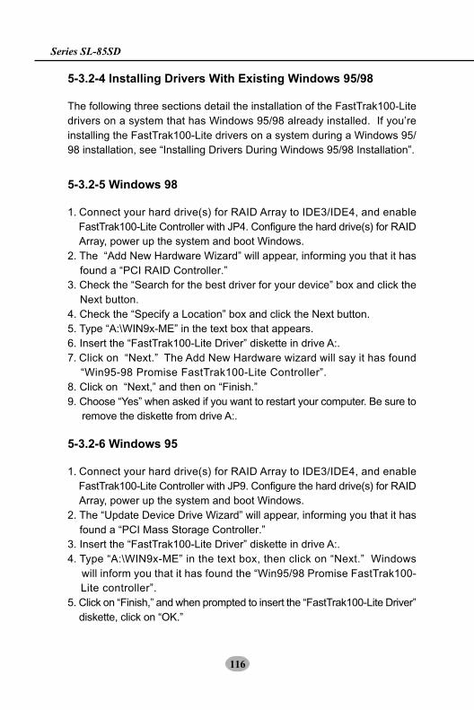
Series SL-85SD
116
5-3.2-5 Windows 98
1. Connect your hard drive(s) for RAID Array to IDE3/IDE4, and enable FastTrak100-Lite Controller with JP4. Configure the hard drive(s) for RAID Array, power up the system and boot Windows.2. The “Add New Hardware Wizard” will appear, informing you that it has found a “PCI RAID Controller.”3. Check the “Search for the best driver for your device” box and click the Next button.4. Check the “Specify a Location” box and click the Next button.5. Type “A:\WIN9x-ME” in the text box that appears.6. Insert the “FastTrak100-Lite Driver” diskette in drive A:.7. Click on “Next.” The Add New Hardware wizard will say it has found “Win95-98 Promise FastTrak100-Lite Controller”.8. Click on “Next,” and then on “Finish.”9. Choose “Yes” when asked if you want to restart your computer. Be sure to remove the diskette from drive A:.
5-3.2-6 Windows 95
1. Connect your hard drive(s) for RAID Array to IDE3/IDE4, and enable FastTrak100-Lite Controller with JP9. Configure the hard drive(s) for RAID Array, power up the system and boot Windows.2. The “Update Device Drive Wizard” will appear, informing you that it has found a “PCI Mass Storage Controller.”3. Insert the “FastTrak100-Lite Driver” diskette in drive A:.4. Type “A:\WIN9x-ME” in the text box, then click on “Next.” Windows will inform you that it has found the “Win95/98 Promise FastTrak100- Lite controller”.5. Click on “Finish,” and when prompted to insert the “FastTrak100-Lite Driver” diskette, click on “OK.”
5-3.2-4 Installing Drivers With Existing Windows 95/98
The following three sections detail the installation of the FastTrak100-Litedrivers on a system that has Windows 95/98 already installed. If you’reinstalling the FastTrak100-Lite drivers on a system during a Windows 95/98 installation, see “Installing Drivers During Windows 95/98 Installation”.
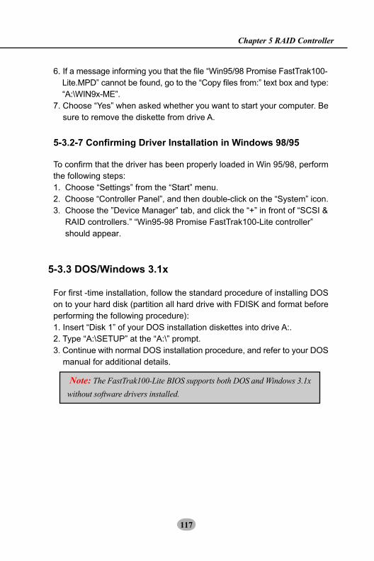
Chapter 5 RAID Controller
117
6. If a message informing you that the file “Win95/98 Promise FastTrak100- Lite.MPD” cannot be found, go to the “Copy files from:” text box and type: “A:\WIN9x-ME”.7. Choose “Yes” when asked whether you want to start your computer. Be sure to remove the diskette from drive A.
5-3.2-7 Confirming Driver Installation in Windows 98/95
To confirm that the driver has been properly loaded in Win 95/98, performthe following steps:1. Choose “Settings” from the “Start” menu.2. Choose “Controller Panel”, and then double-click on the “System” icon.3. Choose the ”Device Manager” tab, and click the “+” in front of “SCSI & RAID controllers.” “Win95-98 Promise FastTrak100-Lite controller” should appear.
5-3.3 DOS/Windows 3.1x
For first -time installation, follow the standard procedure of installing DOSon to your hard disk (partition all hard drive with FDISK and format beforeperforming the following procedure):1. Insert “Disk 1” of your DOS installation diskettes into drive A:.2. Type “A:\SETUP” at the “A:\” prompt.3. Continue with normal DOS installation procedure, and refer to your DOS manual for additional details.
Note: The FastTrak100-Lite BIOS supports both DOS and Windows 3.1x
without software drivers installed.
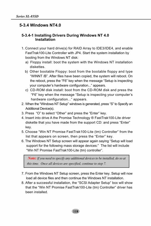
Series SL-85SD
118
5-3.4 Windows NT4.0
5-3.4-1 Installing Drivers During Windows NT 4.0 Installation
1. Connect your hard drive(s) for RAID Array to IDE3/IDE4, and enable FastTrak100-Lite Controller with JP4. Start the system installation by booting from the Windows NT disk: a) Floppy install: boot the system with the Windows NT installation diskettes. b) Other bootable Floppy: boot from the bootable floppy and type “WINNT /B”. After files have been copied, the system will reboot. On the reboot, press the “F6” key when the message “Setup is inspecting your computer’s hardware configuration...” appears. c) CD-ROM disk install: boot from the CD-ROM disk and press the “F6” key when the message “Setup is inspecting your computer’s hardware configuration...” appears.2. When the “Windows NT Setup” windows is generated, press “S” to Specify an Additional Device(s).3. Press “O” to select “Other” and press the “Enter” key.4. Insert into drive A the Promise Technology ® FastTrak100-Lite driver diskette that you have made from the support CD: and press “Enter” key.5. Choose “Win NT Promise FastTrak100-Lite (tm) Controller” from the list that appears on screen, then press the “Enter” key.6. The Windows NT Setup screen will appear again saying “Setup will load support for the following mass storage devices:” The list will include “Win NT Promise FastTrak100-Lite (tm) controller”.
7. From the Windows NT Setup screen, press the Enter key. Setup will now load all device files and then continue the Windows NT installation.8. After a successful installation, the “SCSI Adapter Setup” box will show that the “Win NT Promise FastTrak100-Lite (tm) Controller” driver has been installed.
Note: If you need to specify any additional devices to be installed, do so at
this time. Once all devices are specified, continue to step 7.

Chapter 5 RAID Controller
119
With your bootable hare drive connected to IDE1/IDE2 and FastTrak100-Lite enabled by JP4, boot Win NT4.0. 1. Choose “Settings” from the “Start” menu. 2. Choose “Controller Panel” from the “Settings” menu. 3. Double-click on the “SCSI Adapters” icon, which generates the “SCSI Adapters” dialog box. 4. Choose “Drivers,” and then press “Add.” 5. In the “Install Drivers” dialog box, press “Have Disk...” 6. When the “Install From Disk” appears, insert into Drive A the “FastTrak100- Lite Driver” diskette that you have made from support CD:. 7. Type “A:\NT4” in the text box window, then choose “OK.” 8. When the “Install Driver” dialog box appears, select “ Win NT Promise FastTrak100-Lite controller” and then press “OK.” 9. When the “Select SCSI Adapter Option” dialog box appears, press “Install”.10. After a successful installation, the “SCSI Adapter Setup” box will show that the “Win NT Promise FastTrak100-Lite (tm) Controller” driver has been installed.11. Power off your system.12. Now you can move the boot drive to the FastTrak100-LiteController.
5-3.4-2 Installing Drivers With Existing Windows NT4.0
WARNING:WARNING: Your must first complete installing the driver before moving
the boot drive containing the existing Windows 2000 operating system on to
the FastTrak100-Lite controller (e.g. IDE3/IDE4). On mainboard 65EP+,
IDE1/0 are for system IDE controller, while IDE3 & IDE4 are for RAID IDE
controller.

Series SL-85SD
120
MEMOMEMO
APPENDIX
121
APPENDICESAPPENDICESAPPENDICESAPPENDICESAPPENDICES
Appendix-1 Identifying BIOS Version and BIOS Part NumberAppendix-2 Identifying Mainboard Model NumberAppendix-3 Technical Terms
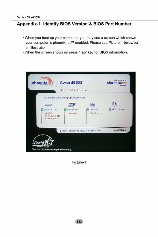
Series SL-85SD
122
Appendix-1 Identify BIOS Version & BIOS Part Number
• When you boot up your computer, you may see a screen which shows your computer is phoenixnet™ enabled. Please see Picture-1 below for an illustration.• When the screen shows up press “Tab” key for BIOS information.
Picture-1
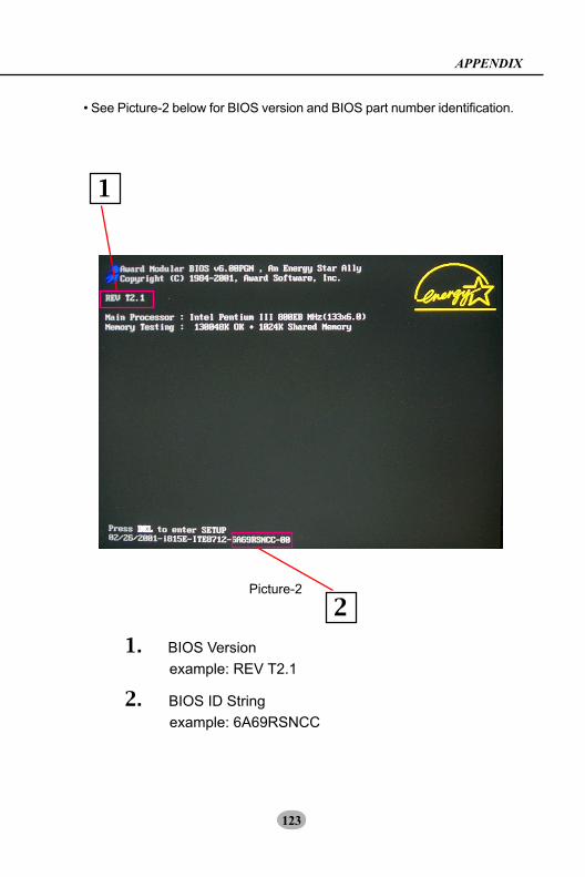
APPENDIX
123
• See Picture-2 below for BIOS version and BIOS part number identification.
2
1
1. BIOS Version
example: REV T2.1
2. BIOS ID String
example: 6A69RSNCC
Picture-2
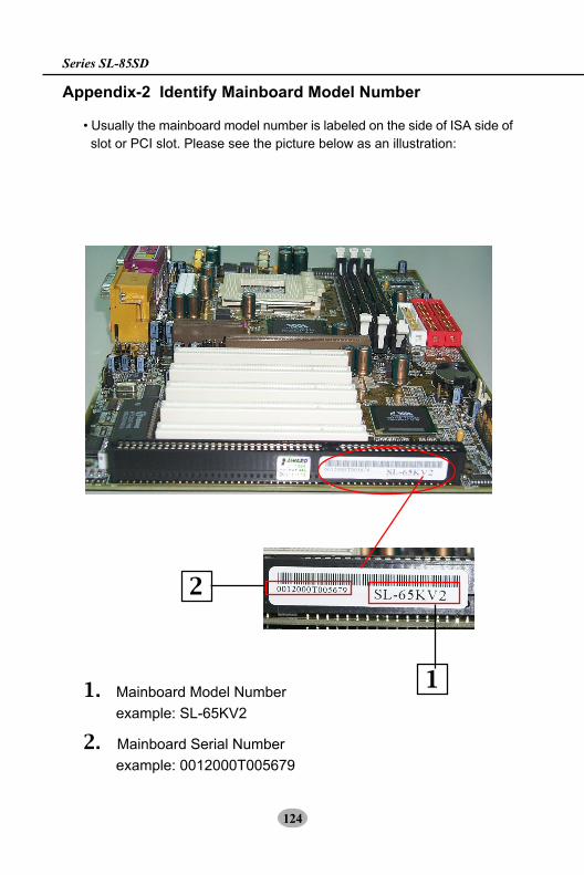
Series SL-85SD
124
1. Mainboard Model Number
example: SL-65KV2
2. Mainboard Serial Number
example: 0012000T005679
Appendix-2 Identify Mainboard Model Number
• Usually the mainboard model number is labeled on the side of ISA side of slot or PCI slot. Please see the picture below as an illustration:
2
1
APPENDIX
125
Appendix-3 Technical Terms
AC’97AC’97 is a device designed to include a digital processor for modem andan audio CODEC for analog I/O. These two parts are linked together byAC’97 link bus. Putting the digital processor into the main system chipsetwill reduce the cost of sound/modem onboard solution.
ACPI (Advanced Configuration & Power Interface)ACPI is developed together by Intel, Microsoft and Toshiba. Thisinterface provides a channel of management of the PC system and itshardware such as CPU and BIOS, pushing the PC power management to amore advanced and user-friendly level.
AGP (Accelerated Graphic Port)AGP is a bus interface targeted for high-performance 3D graphics. AGPtakes advantage of both rising and falling edge of the 66MHz clock. For2X AGP, the data transfer rate is 66MHz x 4byte x 2 = 528MB/s. AGP4X mode is 66MHz x 4byte x 4 = 1056MB/s.
AMR (Audio/Modem Riser)AMR is an interface to connect the CODEC circuit of AC’97 sound/modem solution to the mainboard through an AMR card and an AMRconnector.
APM (Advanced Power Management)APM is developed by Intel and Microsoft , intending for PC powermanagement through the system BIOS. Through APM, the PC powerconsumption can be reduced to 5W or lower.
ATA (AT Attachment), ATA/66, ATA/100ATA is the specification of disk drive interface, that integrates thecontroller on the disk drive itself with the IDE technology.
ATA/66 uses both rising edge and falling edge to provide a data transferrate 16.6MB/s x4 = 66MB/s. To use ATA/66, you need special ATA/66IDE cable.
ATA/100 also uses both rising edge and falling edge as ATA/66, but clockcycle time is reduced to 40ns. The data transfer rate is (1/40ns) x 2 bytes x2 = 100MB/s. To use ATA/100, you need special 80-wire IDE cable, thesame as ATA/66.
Series SL-85SD
126
BIOS (Basic Input/Output System)BIOS is a set of assembly routine/program that resides in EPROM orFlash ROM. BIOS controls Input/output devices and other hardwaredevices of the mainboard. Generally, operation system and drivers willaccess BIOS before accessing hardware devices so as to enhance theportability of the hardware devices.
Bus Master IDE (DMA mode)An IDE interface is an interface for mass storage devices, in which thecontroller is integrated into the disk or CD-ROM itself. To reduce theworkload of the CPU, the bus master IDE device transfers data from/tomemory without interrupting CPU, and releases CPU to operateconcurrently while data is transferring between memory and IDE device.You need the bus master IDE driver and the bus master IDE HDD tosupport bus master IDE mode.
CAS (Column Address Strobe)CAS is a technology of DRAM writes and reads. The number of clockcycles of the CAS signals is depending on the DRAM timing.
CNR (Communication and Networking Riser)CNR interface provides a cost reducing method of implementing LAN,home networking, DSL, USB, wireless, audio and modem subsystemsthrough a CNR card and a CNR connector.
CODEC (Coder and Decoder)Normally, CODEC means a circuit that can do digital to analogconversion and vice versa. It is part of AC’97 sound/modem solution.
DDR (Double Data Rated) SDRAMDDR SDRAM essentially doubles the memory speed of SDRAMswithout increasing the clock frequency.
DIMM (Dual In Line Memory Module)DIMM socket is built with a 168-pin assignment and supports 64-bit data.DIMM can be single or double sided. The golden finger signals on eachside of the module are different, and that is why it is called Dual In Line.Almost all DIMMs are made with SDRAM now, which operate at 3.3V.Some old DIMMs are made by FPM/EDO and only operate at 5V.
APPENDIX
127
DMA (Direct Memory Access)Channel for communications between memory and surrounding devices.
ECC (Error Checking and Correction)The ECC algorithm has the ability to detect double-bit error andautomatically correct single-bit error while parity mode can only detectsingle-bit error.
ECP (Enhanced Communication Port)ECP is a technology designed to improved I/O for parallel ports.
EPP (Enhanced Parallel Port)EPP is a standard that supports data transfer rates of up to 500 kps forparallel printers
EDO (Extended Data Output) MemoryUnlike traditional FPM (Fast Page Mode) memory that tri-states thememory output data to start the pre-charge activity, EDO DRAM holdsthe memory data valid until the next memory access cycle, which issimilar to pipeline effect in reducing one clock state.
EEPROM (Electronic Erasable Programmable ROM)Both EEPROM and Flash ROM can be re-programmed by electronicsignals, but the interface technology is different. Size of EEPROM ismuch smaller than flash ROM. BIOS is now generally stored inEEPROM or Flash ROM.
EPROM (Erasable Programmable ROM)Traditional mainboard stores BIOS codes in EPROM which can only beerased by ultra-violet (UV) light. If BIOS has to be updated, you need toremove EPROM from mainboard, clear data by UV light, re-program, andthen insert it back to socket.
FC-PGA (Flip Chip-Pin Grid Array)FC means Flip Chip, while FC-PGA is a new package of Intel forPentium III CPU. It is compatible with SKT370 socket, but requiresmainboard to add some signals on socket 370.
Flash ROMFlash ROM can be re-programmed by electronic signals. It is easier forBIOS to upgrade by a flash utility, but it is also easier to be infected byvirus. Because of increase of new functions, BIOS size is increased from64KB to 256KB (2M bit) or more.
Series SL-85SD
128
FSB (Front Side Bus)FSB is the data channel connecting the Processor to chipset, RAM,mainboard buses, AGP socket etc. Its speed is in terms of MHz and istalked to as FSB clock:FSB Clock means CPU external bus clock.CPU internal clock = CPU FSB Clock x CPU Clock Ratio
IEEE 1394IEEE 1394 is a low-cost digital transfer interface with transfer rate at 100,200 or 400 Mbps. It provides solutions of connecting digital televisiondevices and Serial Bus Management. There are two type of IEEE 1394data transfer: asynchronous and isochronous. Isochronous data channelsprovide guaranteed data transport at a pre-determined rate. This isespecially important for time-critical multimedia data where just-in-timedelivery eliminates the need for costly buffering.
Parity BitThe parity bit mode of error detection uses 1 parity bit for each byte.Normally it is even parity mode, that is, each time the memory data isupdated, parity bit will be adjusted to have even count “1” for each byte.Next time when memory is read with odd number of “1”, the parity erroris occurred and this is called single bit error detection.
PC-100 DIMMSDRAM DIMM that supports 100MHz CPU FSB bus clock.
PC-133 DIMMSDRAM DIMM that supports 133MHz CPU FSB bus clock.
PC-1600 or PC-2100 DDR SDRAMPC-1600 DDR SDRAM with a 64-bit data bus doubles the data transferrate of PC100 SDRAM and hence provides data transfer bandwidth up to100x64/8x2=1600MB/s. PC2100 DDR SDRAM doubles the data transferrate of PC-133 and hence provides data transfer bandwidth up to 133x64/8x2=2100MB/s.
PCI (Peripheral Component Interface) BusA high speed data channel for the internal connection of peripheraldevices and the computer system through a PCI expansion card.
PnP (Plug and Play)The PnP specification suggests a standard register interface for both BIOSand operating system (such as Windows 95). These registers are used byBIOS and operating system to configure system resource and prevent any
APPENDIX
129
conflicts. PnP BIOS or operating system will automatically allocate theIRQ/DMA/Memory. Currently, almost all the PCI cards and most ISAcards are already PnP compliant.
POST (Power-On Self Test)The BIOS self-test procedure after power-on. It is generally the first orthe second program shown on your monitor screen during system boot.
RAS (Row Address Strobe)RAS is a technology that DRAM writes and reads to the Row addresses,while a CAS (Column Address Strobe) signal is used to validate thecolumn address. The signals are generally sent CAS before RAS.(in Network field, RAS stands for Remote Access Services).
RDRAM (Rambus DRAM)Rambus DRAM is a memory technology that uses large burst mode datatransfer of up to 1.6GHz. It is import to know that RDRAM technologyhelps set up a system level improvement, not just a component upgrade.
RIMM (Rambus Inline Memory Module)RIMM is built with a 184-pin architecture module that supports RDRAMmemory technology. A RIMM memory module may contain up tomaximum of 16 RDRAM devices.
SDRAM (Synchronous DRAM)SDRAM is one of the Dynamic Random Access Memory (DRAM)technologies that allow DRAM to use the same clock as the CPU hostclock (EDO and FPM are asynchronous and do not have clock signal).SDRAM comes in 64-bit 168-pin DIMM and operates at 3.3V.
SIMM (Single In Line Memory Module)SIMM socket is only 72-pin, and is only single side. The golden fingersignals on each side of PCB are identical. That is why it is called SingleIn Line. SIMM is made of FPM or EDO DRAM and supports 32-bit data.SIMM is phased out in current mainboard design.
SPD (Serial Presence Detect)SPD is a small ROM or EEPROM device resided on the DIMM orRIMM. Memory module information such as DRAM timing and chipparameters can be stored into SPD so that BIOS can access it and use it todecide best timing for this DIMM or RIMM.
Series SL-85SD
130
UART (Universal Asynchronous Receiver/transmitter)UART is built in a chip that controls the data sent to and received from aserial port. A 16550 UART is now standard in most PCs, and supportsmodem speed up to 57,600 bps and beyond and direct connect speed of115,200 bps. Many UARTs have built-in errors in the internal code andjust do not work correctly with many external modems. UART is alsofound as the serial interface on internal modem.
Ultra DMAUltra DMA (or, more accurately, Ultra DMA/33) is a protocol fortransferring data at 33.3MB/s between a hard disk drive through thecomputer’s data path (or bus) to the computer’s random access memory(RAM). The transfer data is twice as fast as the previous Direct AccessMemory (DMA) interface. The latest Ultra DMA has advanced to UltraDMA/66 and Ultra DMA/100.16.6MB/s x2 = 33MB/s16.6MB/s x4 = 66MB/s16.6MB/s x6 = 100MB/s
USB (Universal Serial Bus)USB is a 4-pin serial peripheral bus that is capable of cascading low/medium speed peripherals (less than 10Mbit/s) such as keyboard, mouse,joystick, scanner, printer and modem.
VCM (Virtual Channel Memory)NEC’s Virtual Channel Memory (VCM) is a new DRAM corearchitecture that dramatically improves the memory system’s ability toservice multimedia requirements. VCM increases memory bus efficiencyand performance of any DRAM technology by providing a set of faststatic registers between the memory core and I/O pins. Using VCMtechnology results in reduced data access latency and reduced powerconsumption.
ZIP fileZip file is a compressed file with a reduced file size.

APPENDIX
131
MEMOMEMO