Embed Size (px)
DESCRIPTION
.
Citation preview
Mechanical Systems and Signal Processing (2001) 15(5), 855}871doi:10.1006/mssp.2001.1411, available online at http://www.idealibrary.com on
MATHEMATICAL MODELLING AND COMPUTERSIMULATIONS AS AN AID TO GEARBOX
DIAGNOSTICS
WALTER BARTELMUS
Wroclaw University of Technology, Pl. Teatralny 2, 50-051 Wroclaw, Poland
The paper deals with mathematical modelling and computer simulation as a tool foraiding gearbox diagnostic inference. The results of computer simulations and results ob-tained by laboratory rigs and "eld practice are compared. For investigation by computersimulations di!erent factors are taken into consideration. The factors are divided into fourgroups: design factors, production technology factors, operational factors and change ofcondition factors. Using computer simulation and taking these factors into account: design,production technology, operation and condition change factors lead to DPTOCC inferringdiagnostic information of the gearing system condition. The model for a system witha one-stage gearbox with torsional vibration is presented here as also are models for systemswith a one-stage gearbox where both torsional and lateral vibration are taken into consid-eration and a system with a two-stage gearbox.
( 2001 Academic Press
1. INTRODUCTION
The modelling of gearbox dynamic behaviour belongs to the fundamental problems ofmechanical system modelling. The problem has been the subject of many papers [1}11].The model presented by Muller in [7] has received a lot of attention in Poland. It wasdiscussed, for example, in [8}11]. The model is a two-parameter (sti!ness and damping) onein which the inertia of two wheels has been reduced to one mass equivalent to a one-stagegearbox.
The author of the present paper has found that more sophisticated models are needed todescribe the gearbox dynamics properly [12}22] as presented in papers [1}5]. Mathemat-ical modelling and computer simulation can be applied to gearbox dynamic examinationsto support diagnostic signal evaluation for diagnostic inference. This is the main aim of thepresented research. The computer simulation is based on a mathematical model presentedin [12] and [19}21]. General information, on gearing, needed for the computer simulationof gearbox behaviour is given in [19] and [20]. Some results of computer simulationssupporting diagnostic inference were presented in [12}22]. The papers show that math-ematical modelling and computer simulation enable the detailed investigation of thedynamic properties of a gearing system. All the basic factors such as: design, productiontechnology, operation and change of the gearing system condition, which have a bearing onthe vibration generated by a gearset, can be investigated. Using computer simulation andtaking these factors into account: design, production technology, operation and conditionchange factors lead to DPTOCC inferring diagnostic information of the gearing systemcondition. The causes of vibration in gearboxes are mainly tooth errors, which togetherwith a gearing de#ection show the gearing condition and the vibration is an indication ofthem. The computer simulation results are referred to the laboratory rig investigationresults presented in [23] and to the "eld measurements reported in [24}27]. As mentioned
0888}3270/01/050855#17 $35.00/0 ( 2001 Academic Press
856 W. BARTELMUS
above, the vibration of a gearbox indicates whether there are tooth errors in it. The errorsappear at the production stage and during change of condition. The nature of the gearwheel interaction is such that non-linear phenomena occur caused by friction, inter-toothbacklash, impact-like inter-tooth forces and periodic changes in tooth sti!ness. As a result,inter-tooth forces may exceed the force values, which follow from the gearbox system's ratedmoment. Mathematical description allowing one to include these phenomena in theequation of motion is given in [19}20]. The inter-tooth forces increase dramatically inunstable conditions. A one-stage gear system operates in resonance conditions and isunstable when the gearbox system's mesh frequency is equal to its natural frequency. Insuch conditions the inter-tooth forces are two times or more bigger than the rated forces.The phenomenon of resonance has not been investigated fully for gearbox systems but someconsiderations are given in [13, 19, 22].
Computer simulations reveal that conditions similar to those occurring at resonance mayresult as errors (pitting, scu$ng of teeth #anks and failure of bearings) increase during theservice of a gearbox system. In the present paper, current developments in gearboxmodelling are presented with reference to the previous papers by the author. It is shown thata #exible coupling and an error mode random parameter have an in#uence on gearboxstability (tooth separation). An error mode is described by several parameters, i.e. maximumerror value, shape of error plot and random error #uctuation depth.
2. MODELLING OF GEARBOX SYSTEM
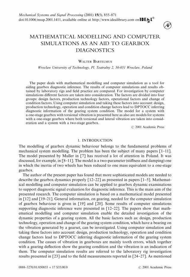
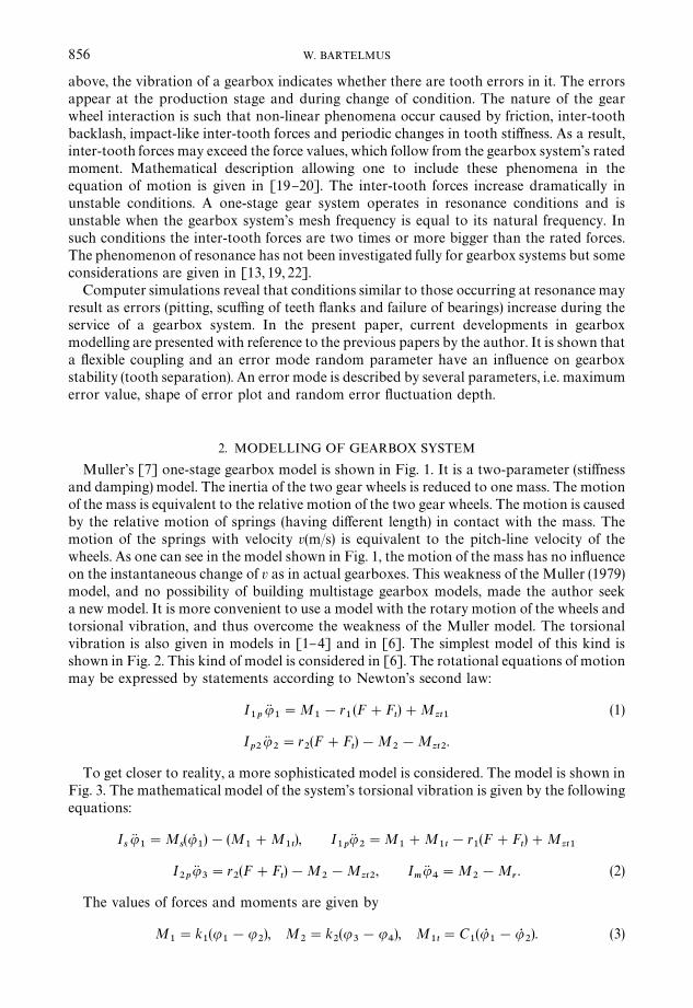
Muller's [7] one-stage gearbox model is shown in Fig. 1. It is a two-parameter (sti!nessand damping) model. The inertia of the two gear wheels is reduced to one mass. The motionof the mass is equivalent to the relative motion of the two gear wheels. The motion is causedby the relative motion of springs (having di!erent length) in contact with the mass. Themotion of the springs with velocity v(m/s) is equivalent to the pitch-line velocity of thewheels. As one can see in the model shown in Fig. 1, the motion of the mass has no in#uenceon the instantaneous change of v as in actual gearboxes. This weakness of the Muller (1979)model, and no possibility of building multistage gearbox models, made the author seeka new model. It is more convenient to use a model with the rotary motion of the wheels andtorsional vibration, and thus overcome the weakness of the Muller model. The torsionalvibration is also given in models in [1}4] and in [6]. The simplest model of this kind isshown in Fig. 2. This kind of model is considered in [6]. The rotational equations of motionmay be expressed by statements according to Newton's second law:
I1p
uK1"M
1!r
1(F#F
t)#M
zt1(1)
Ip2
uK2"r
2(F#F
t)!M
2!M
zt2.
To get closer to reality, a more sophisticated model is considered. The model is shown inFig. 3. The mathematical model of the system's torsional vibration is given by the followingequations:
IsuK1"M
s(uR
1)!(M
1#M
1t), I
1puK
2"M
1#M
1t!r
1(F#F
t)#M
zt1
I2p
uK3"r
2(F#F
t)!M
2!M
zt2, I
muK4"M
2!M
r. (2)
The values of forces and moments are given by
M1"k
1(u
1!u
2), M
2"k
2(u
3!u
4), M
1t"C
1(uR
1!uR
2). (3)
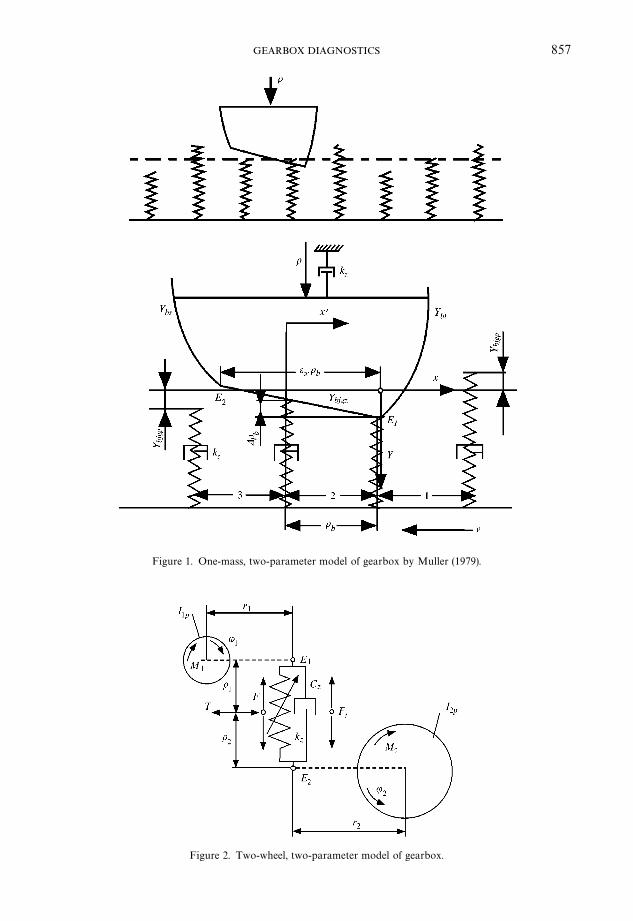
Figure 1. One-mass, two-parameter model of gearbox by Muller (1979).
Figure 2. Two-wheel, two-parameter model of gearbox.
857GEARBOX DIAGNOSTICS
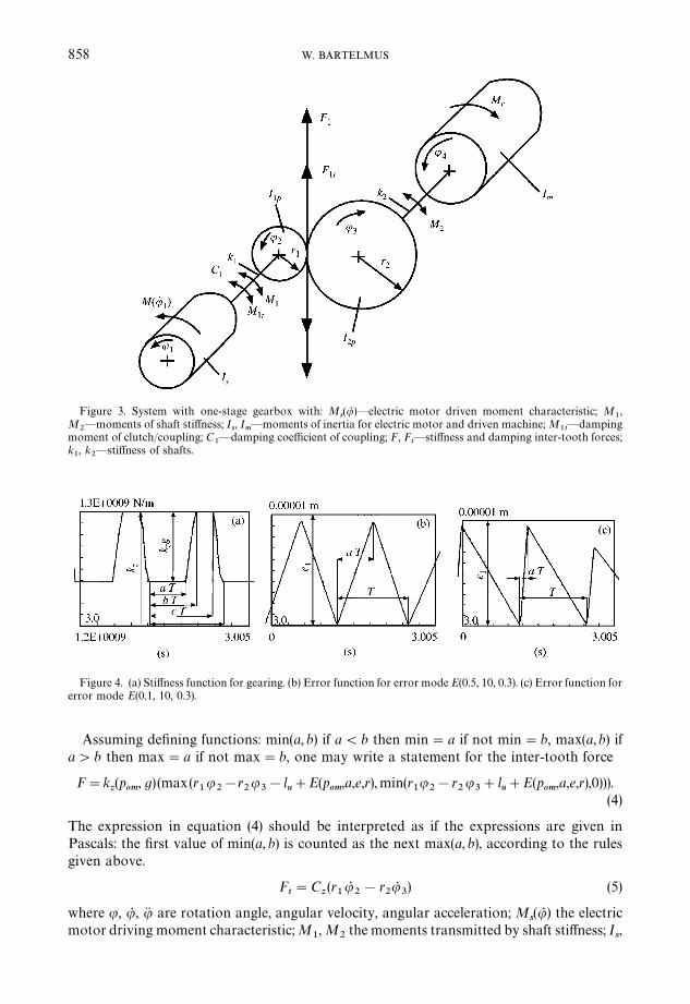
Figure 3. System with one-stage gearbox with: Ms(uR )*electric motor driven moment characteristic; M
1,
M2*moments of shaft sti!ness; I
s, I
m*moments of inertia for electric motor and driven machine; M
1t*damping
moment of clutch/coupling; C1*damping coe$cient of coupling; F, F
t*sti!ness and damping inter-tooth forces;
k1, k
2*sti!ness of shafts.
Figure 4. (a) Sti!ness function for gearing. (b) Error function for error mode E(0.5, 10, 0.3). (c) Error function forerror mode E(0.1, 10, 0.3).
858 W. BARTELMUS
Assuming de"ning functions: min(a, b) if a(b then min"a if not min"b, max(a,b) ifa'b then max"a if not max"b, one may write a statement for the inter-tooth force
F"kz(p
om, g) (max(r
1u
2!r
2u3!l
u#E(p
om,a,e,r),min(r
1u
2!r
2u3#l
u#E(p
om,a,e,r),0))).
(4)
The expression in equation (4) should be interpreted as if the expressions are given inPascals: the "rst value of min(a, b) is counted as the next max(a, b), according to the rulesgiven above.
Ft"C
z(r1uR
2!r
2uR
3) (5)
where u, uR , uK are rotation angle, angular velocity, angular acceleration; Ms(uR ) the electric
motor driving moment characteristic; M1, M
2the moments transmitted by shaft sti!ness; I
s,
859GEARBOX DIAGNOSTICS
Im
the moments of inertia for electric motor and driven machine; M1t
the damping momentof clutch/coupling; C
1the damping coe$cient of coupling; F, F
tthe sti!ness and damping
inter-tooth forces; k1, k
2the sti!ness of shafts; M
zt1, M
zt2the inter-tooth moments of
friction, Mzt1
"¹o1; M
zt2"¹o
2where ¹ is the inter-tooth friction force (Fig. 2), where
kz(p
om, g) is the gearing sti!ness function, obtained according to considerations given in [7]
and [28]; (recently, FE models [5, 11] have been developed for assessing gearing sti!nessand the related static transmission error [5]) r
1, r
2the gear base radii; l
uthe inter-tooth
backlash; E(pom
, a, e, r) the error mode function, where pom"frac(u
2z1/(2n)); a, e, r are the
parameters of error function; z1
the number of teeth in pinion. A full description ofthe model is given in [12] and after modi"cation*in [19, 20]. For a given pair of teeth thevalue of an error is random and it can be denoted by
e(random)"[1!r(1!li)]e (6)
where e is the maximum error value; r the coe$cient of error scope, range (0}1); lithe
random value, range (0}1).A symbolic description of an error characteristic (error mode) is E(a; e; r); parameters of
the error mode have been described earlier above; a - is given in Fig. 4(b) and (c), it has range(0}1), and it indicates the position of the maximum error value on the line of action. As anexample, an error mode for E(0.5; 10; 0.3) is given in Fig. 4(b) and for E(0.1; 10; 0.3) inFig. 4(c).
In Fig. 4 the value of the sti!ness kz(p
om, g) and the value of the error function E(a; e; r) are
given as a function of time from 3.0 to 3.005 s and a time range is divided into ten equalparts as are the value of k
z(p
om, g) for a range of 1.2}1.3E9 N/m and the value of E(a; e; r) for
the range 0}0.00001 m.As follows from the above discussion, the gearing's dynamic properties depend on
several factors. The factors may be divided, according to [20, 27], into: 1*design factors;2*production technology factors; 3*operation factors; 4*change of condition factors,DPTOCC factors.
Numerical solutions of the di!erential equations are obtained by means of CSSP(Continuous System Simulation Program) given in [29], using the England procedure ofintegration. The procedure is a general procedure of the Runge}Kutta type and it assuresthe stability of integration, even in the case of discontinuity, as well as enabling errorestimation and the automatic change of the integration step. CSSP is now available forWindows [30].
Some properties of gearbox condition vibration signals cannot be studied when using thesystem when only torsion vibration is taken into consideration. Change of gearing condi-tion caused by increased friction between teeth has to be investigated when besides torsionvibration lateral vibrations are also considered. As it is given in paper [16] inter-toothforces are transmitted through the bearings to the housing of a gearbox. These forces actalong the length of an action line E
1E
2, Fig. 2. Friction forces ¹ are perpendicular to the line
of action, see Fig. 2. The change of inter-tooth friction forces may be caused by toothscu$ng. The increased intensity of teeth scu$ng causes the increase of a friction coe$cient.The computer simulation studies have to be done to "nd vibration signal properties forsupporting diagnostic inference, when tooth scu$ng is the problem. There is also a need tostudy the gearbox systems with multiple stages. The model of the system with gearbox withmultiple stages will be presented with the model taking into consideration torsion andlateral vibration. The in#uence of torsion vibration between stages will be investigated. Inpapers [1}4, 6] the clutch damping C
1(N sm), a very important factor, is not taken into
consideration.
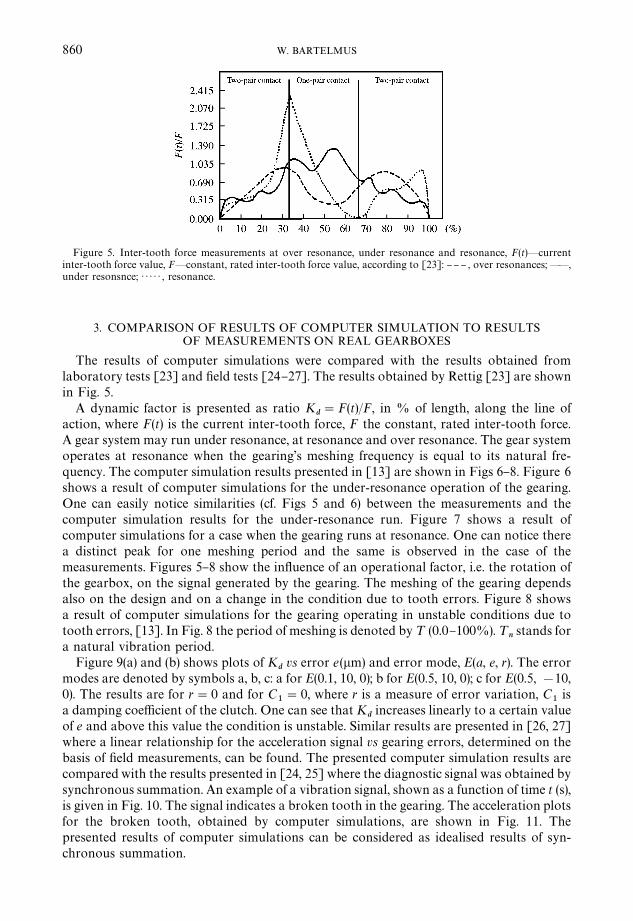
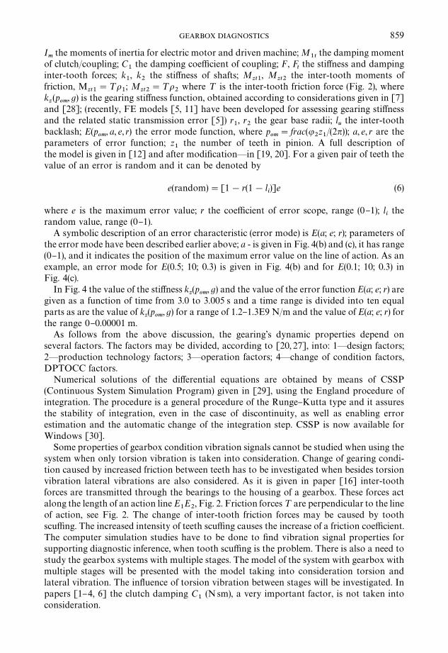
Figure 5. Inter-tooth force measurements at over resonance, under resonance and resonance, F(t)*currentinter-tooth force value, F2constant, rated inter-tooth force value, according to [23]: }} } , over resonances;**,under resonsnce; ) ) ) ) ) , resonance.
860 W. BARTELMUS
3. COMPARISON OF RESULTS OF COMPUTER SIMULATION TO RESULTSOF MEASUREMENTS ON REAL GEARBOXES
The results of computer simulations were compared with the results obtained fromlaboratory tests [23] and "eld tests [24}27]. The results obtained by Rettig [23] are shownin Fig. 5.
A dynamic factor is presented as ratio Kd"F(t)/F, in % of length, along the line of
action, where F(t) is the current inter-tooth force, F the constant, rated inter-tooth force.A gear system may run under resonance, at resonance and over resonance. The gear systemoperates at resonance when the gearing's meshing frequency is equal to its natural fre-quency. The computer simulation results presented in [13] are shown in Figs 6}8. Figure 6shows a result of computer simulations for the under-resonance operation of the gearing.One can easily notice similarities (cf. Figs 5 and 6) between the measurements and thecomputer simulation results for the under-resonance run. Figure 7 shows a result ofcomputer simulations for a case when the gearing runs at resonance. One can notice therea distinct peak for one meshing period and the same is observed in the case of themeasurements. Figures 5}8 show the in#uence of an operational factor, i.e. the rotation ofthe gearbox, on the signal generated by the gearing. The meshing of the gearing dependsalso on the design and on a change in the condition due to tooth errors. Figure 8 showsa result of computer simulations for the gearing operating in unstable conditions due totooth errors, [13]. In Fig. 8 the period of meshing is denoted by ¹ (0.0}100%). ¹
nstands for
a natural vibration period.Figure 9(a) and (b) shows plots of K
dvs error e(lm) and error mode, E(a, e, r). The error
modes are denoted by symbols a, b, c: a for E(0.1, 10, 0); b for E(0.5, 10, 0); c for E(0.5, !10,0). The results are for r"0 and for C
1"0, where r is a measure of error variation, C
1is
a damping coe$cient of the clutch. One can see that Kdincreases linearly to a certain value
of e and above this value the condition is unstable. Similar results are presented in [26, 27]where a linear relationship for the acceleration signal vs gearing errors, determined on thebasis of "eld measurements, can be found. The presented computer simulation results arecompared with the results presented in [24, 25] where the diagnostic signal was obtained bysynchronous summation. An example of a vibration signal, shown as a function of time t (s),is given in Fig. 10. The signal indicates a broken tooth in the gearing. The acceleration plotsfor the broken tooth, obtained by computer simulations, are shown in Fig. 11. Thepresented results of computer simulations can be considered as idealised results of syn-chronous summation.
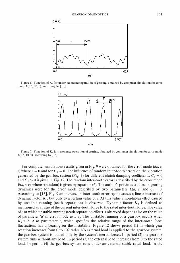
Figure 6. Function of Kdfor under-resonance operation of gearing, obtained by computer simulation for error
mode E(0.5, 10, 0), according to [13].
Figure 7. Function of Kdfor resonance operation of gearing, obtained by computer simulation for error mode
E(0.5, 10, 0), according to [13].
861GEARBOX DIAGNOSTICS
For computer simulations results given in Fig. 9 were obtained for the error mode E(a, e,r) where r"0 and for C
1"0. The in#uence of random inter-tooth errors on the vibration
generated by the gearbox system (Fig. 3) for di!erent clutch damping coe$cients: C1"0
and C1'0 is given in Fig. 12. The random inter-tooth error is described by the error mode
E(a, e, r), where e(random) is given by equation (6). The author's previous studies on gearingdynamics were for the error mode described by two parameters E(a, e) and C
1"0.
According to [13], Fig. 9 an increase in inter-tooth error e(lm) causes a linear increase ofdynamic factor K
d, but only to a certain value of e. At this value a non-linear e!ect caused
by unstable running (teeth separation) is observed. Dynamic factor Kd
is de"ned asmentioned as a ratio of the current inter-tooth force to the rated inter-tooth force. The valueof e at which unstable running (teeth separation e!ect) is observed depends also on the valueof parameter &a' in error mode E(a, e). The unstable running of a gearbox occurs whenK
d'2. Also parameter r, which speci"es the relative range of the inter-tooth force
#uctuation, has a bearing on the instability. Figure 12 shows period (1) in which gearrotation increases from 0 to 107 rad/s. No external load is applied to the gearbox system;the gearbox system is loaded only by the system's inertia forces. In period (2) the gearboxsystem runs without any load. In period (3) the external load increases from 0 to the ratedload. In period (4) the gearbox system runs under an external stable rated load. In the
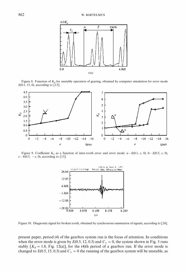
Figure 8. Function of Kdfor unstable operation of gearing, obtained by computer simulation for error mode
E(0.5, 15, 0), according to [13].
Figure 9. Coe$cient Kd
as a function of inter-tooth error and error mode: a*E(0.1, e, 0), b*E(0.5, e, 0),c*E(0.5, !e, 0), according to [13].
Figure 10. Diagnostic signal for broken tooth, obtained by synchronous summation of signals, according to [24].
862 W. BARTELMUS
present paper, period (4) of the gearbox system run is the focus of attention. In conditionswhen the error mode is given by E(0.5, 12, 0.3) and C
1"0, the system shown in Fig. 3 runs
stably [Kd"1.8, Fig. 12(a)], for the (4)th period of a gearbox run. If the error mode is
changed to E(0.5, 15, 0.3) and C1"0 the running of the gearbox system will be unstable, as
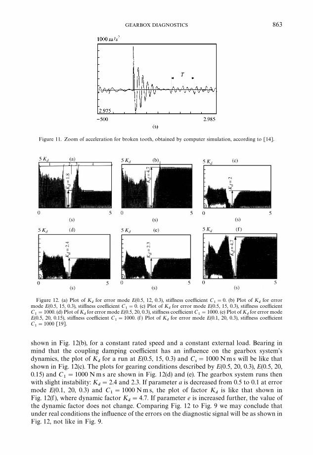
Figure 11. Zoom of acceleration for broken tooth, obtained by computer simulation, according to [14].
Figure 12. (a) Plot of Kd
for error mode E(0.5, 12, 0.3), sti!ness coe$cient C1"0. (b) Plot of K
dfor error
mode E(0.5, 15, 0.3), sti!ness coe$cient C1"0. (c) Plot of K
dfor error mode E(0.5, 15, 0.3), sti!ness coe$cient
C1"1000. (d) Plot of K
dfor error mode E(0.5, 20, 0.3), sti!ness coe$cient C
1"1000. (e) Plot of K
dfor error mode
E(0.5, 20, 0.15), sti!ness coe$cient C1"1000. (f ) Plot of K
dfor error mode E(0.1, 20, 0.3), sti!ness coe$cient
C1"1000 [19].
863GEARBOX DIAGNOSTICS
shown in Fig. 12(b), for a constant rated speed and a constant external load. Bearing inmind that the coupling damping coe$cient has an in#uence on the gearbox system'sdynamics, the plot of K
dfor a run at E(0.5, 15, 0.3) and C
s"1000 Nms will be like that
shown in Fig. 12(c). The plots for gearing conditions described by E(0.5, 20, 0.3), E(0.5, 20,0.15) and C
1"1000 N ms are shown in Fig. 12(d) and (e). The gearbox system runs then
with slight instability: Kd"2.4 and 2.3. If parameter a is decreased from 0.5 to 0.1 at error
mode E(0.1, 20, 0.3) and C1"1000 Nm s, the plot of factor K
dis like that shown in
Fig. 12(f ), where dynamic factor Kd"4.7. If parameter e is increased further, the value of
the dynamic factor does not change. Comparing Fig. 12 to Fig. 9 we may conclude thatunder real conditions the in#uence of the errors on the diagnostic signal will be as shown inFig. 12, not like in Fig. 9.
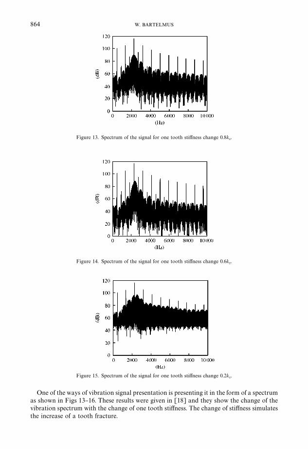
Figure 13. Spectrum of the signal for one tooth sti!ness change 0.8kz.
Figure 14. Spectrum of the signal for one tooth sti!ness change 0.6kz.
Figure 15. Spectrum of the signal for one tooth sti!ness change 0.2kz.
864 W. BARTELMUS
One of the ways of vibration signal presentation is presenting it in the form of a spectrumas shown in Figs 13}16. These results were given in [18] and they show the change of thevibration spectrum with the change of one tooth sti!ness. The change of sti!ness simulatesthe increase of a tooth fracture.
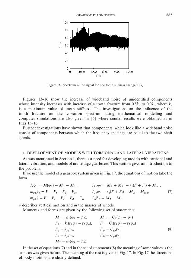
Figure 16. Spectrum of the signal for one tooth sti!ness change 0.0kz.
865GEARBOX DIAGNOSTICS
Figures 13}16 show the increase of wideband noise of unidenti"ed componentswhose intensity increases with increase of a tooth fracture from 0.8k
zto 0.0k
z, where k
zis a maximum value of tooth sti!ness. The investigations on the in#uence of thetooth fracture on the vibration spectrum using mathematical modelling andcomputer simulations are also given in [6] where similar results were obtained as inFigs 13}16.
Further investigations have shown that components, which look like a wideband noiseconsist of components between which the frequency spacings are equal to the two shaftspeeds.
4. DEVELOPMENT OF MODELS WITH TORSIONAL AND LATERAL VIBRATIONS
As was mentioned in Section 1, there is a need for developing models with torsional andlateral vibration, and models of multistage gearboxes. This section gives an introduction tothe problem.
If we use the model of a gearbox system given in Fig. 17, the equations of motion take theform
IsuK
1"M(u5
1)!M
1!M
1t, I
1puK
2"M
1#M
1t!r
1(F#F
t)#M
zt1,
mp1
yK3"F#F
t!F
g!F
gt, I
2puK
4!r
2(F#F
t)!M
2!M
zt2,
mp2
yK"F#Ft!F
d!F
d!F
dtImuK
6"M
2!M
r.
(7)
y describes vertical motion and m the masses of wheels.Moments and forces are given by the following set of statements:
M1"k
1(u
1!u
2), M
1t"C
1(uR
1!uR
2)
F1"k
z(r1u2!r
2u4), F
t"C
z(r1uR
2!r
2uR
4)
Fg"k
ygy3, F
gt"C
ygyR3
Fd"k
ydy5, F
dt"C
ydy5
M2"k
2(u
4!u
6).
(8)
In the set of equations (7) and in the set of statements (8) the meaning of some values is thesame as was given before. The meaning of the rest is given in Fig. 17. In Fig. 17 the directionsof body motions are clearly de"ned.
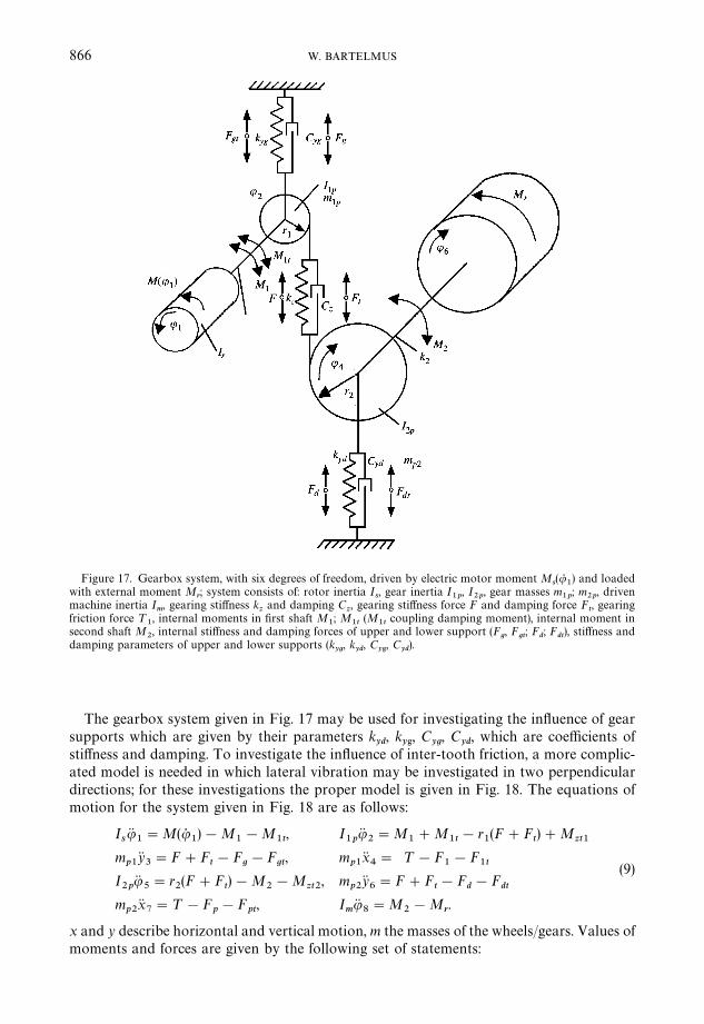
Figure 17. Gearbox system, with six degrees of freedom, driven by electric motor moment Ms(uR
1) and loaded
with external moment Mr; system consists of: rotor inertia I
s, gear inertia I
1p, I
2p, gear masses m
1p; m
2p, driven
machine inertia Im, gearing sti!ness k
zand damping C
z, gearing sti!ness force F and damping force F
t, gearing
friction force ¹1, internal moments in "rst shaft M
1; M
1t(M
1tcoupling damping moment), internal moment in
second shaft M2, internal sti!ness and damping forces of upper and lower support (F
g, F
gt; F
d; F
dt), sti!ness and
damping parameters of upper and lower supports (kyg, k
yd, C
y', C
yd).
866 W. BARTELMUS
The gearbox system given in Fig. 17 may be used for investigating the in#uence of gearsupports which are given by their parameters k
yd, k
y', C
yg, C
yd, which are coe$cients of
sti!ness and damping. To investigate the in#uence of inter-tooth friction, a more complic-ated model is needed in which lateral vibration may be investigated in two perpendiculardirections; for these investigations the proper model is given in Fig. 18. The equations ofmotion for the system given in Fig. 18 are as follows:
IsuK1"M(u5
1)!M
1!M
1t, I
1puK2"M
1#M
1t!r
1(F#F
t)#M
zt1m
p1yK3"F#F
t!F
g!F
gt, m
p1xK4" ¹!F
1!F
1tI2p
uK5"r
2(F#F
t)!M
2!M
zt2, m
p2yK6"F#F
t!F
d!F
dtm
p2xK7"¹!F
p!F
pt, I
muK8"M
2!M
r.
(9)
x and y describe horizontal and vertical motion, m the masses of the wheels/gears. Values ofmoments and forces are given by the following set of statements:
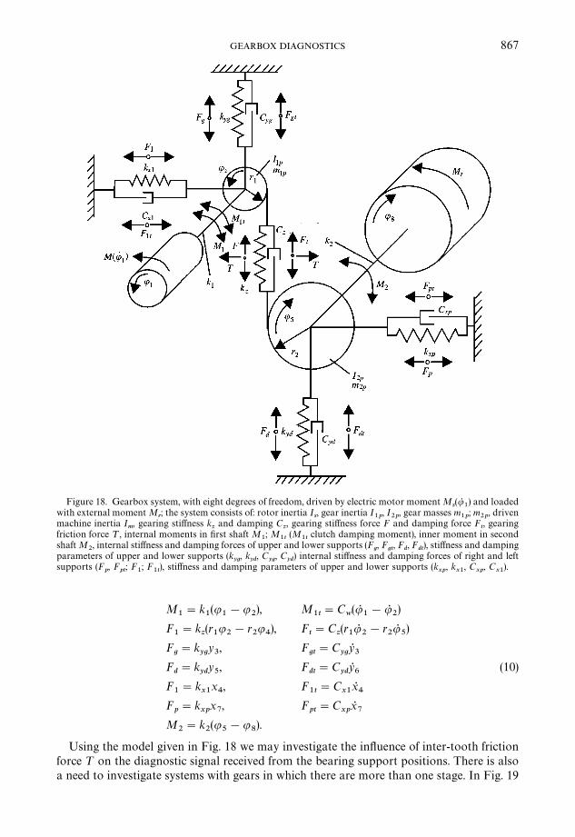
Figure 18. Gearbox system, with eight degrees of freedom, driven by electric motor moment Ms(uR
1) and loaded
with external moment Mr; the system consists of: rotor inertia I
s, gear inertia I
1p, I
2p, gear masses m
1p; m
2p, driven
machine inertia Im, gearing sti!ness k
zand damping C
z, gearing sti!ness force F and damping force F
t, gearing
friction force ¹, internal moments in "rst shaft M1; M
1t(M
1tclutch damping moment), inner moment in second
shaft M2, internal sti!ness and damping forces of upper and lower supports (F
g, F
gt, F
d, F
dt), sti!ness and damping
parameters of upper and lower supports (kyg, k
yd, C
yg, C
yd) internal sti!ness and damping forces of right and left
supports (Fp, F
pt; F
1; F
1t), sti!ness and damping parameters of upper and lower supports (k
xp, k
x1, C
xp, C
x1).
867GEARBOX DIAGNOSTICS
M1"k
1(u
1!u
2), M
1t"C
w(uR
1!uR
2)
F1"k
z(r1u2!r
2u4), F
t"C
z(r1uR
2!r
2uR
5)
Fg"k
ygy3, F
gt"C
ygyR3
Fd"k
ydy5, F
dt"C
ydyR6
F1"k
x1x4, F
1t"C
x1xR4
Fp"k
xpx7, F
pt"C
xpxR7
M2"k
2(u
5!u
8).
(10)
Using the model given in Fig. 18 we may investigate the in#uence of inter-tooth frictionforce ¹ on the diagnostic signal received from the bearing support positions. There is alsoa need to investigate systems with gears in which there are more than one stage. In Fig. 19
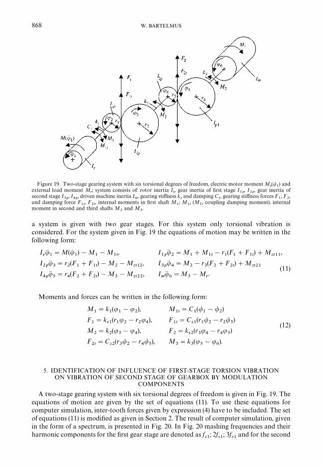
Figure 19. Two-stage gearing system with six torsional degrees of freedom, electric motor moment Ms(uR
1) and
external load moment Mr; system consists of: rotor inertia I
s, gear inertia of "rst stage I
1p, I
2p, gear inertia of
second stage I3p
, I4p
, driven machine inertia Im, gearing sti!ness k
zand damping C
z, gearing sti!ness forces F
1, F
2,
and damping force F1t, F
2t, internal moments in "rst shaft M
1; M
1t(M
1tcoupling damping moment), internal
moment in second and third shafts M2
and M3.
868 W. BARTELMUS
a system is given with two gear stages. For this system only torsional vibration isconsidered. For the system given in Fig. 19 the equations of motion may be written in thefollowing form:
IsuK1"M(u5
1)!M
1!M
1t, I
1puK
2"M
1#M
1t!r
1(F
1#F
1t)#M
zt11,
I2p
uK3"r
2(F
1#F
1t)!M
2!M
zt12, I
3puK
4"M
2!r
3(F
2#F
2t)#M
zt21I4p
uK5"r
4(F
2#F
2t)!M
3!M
zt22, I
muK
6"M
3!M
r.
(11)
Moments and forces can be written in the following form:
M1"k
1(u
1!u
2), M
1t"C
1(uR
1!uR
2)
F1"k
z1(r1u2!r
2u4), F
1t"C
z1(r1uR
2!r
2uR
5)
M2"k
2(u
3!u
4), F
2"k
z2(r3u
4!r
4u
5)
F2t"C
z2(r3uR2!r
4uR5), M
3"k
3(u
5!u
6).
(12)
5. IDENTIFICATION OF INFLUENCE OF FIRST-STAGE TORSION VIBRATIONON VIBRATION OF SECOND STAGE OF GEARBOX BY MODULATION
COMPONENTS
A two-stage gearing system with six torsional degrees of freedom is given in Fig. 19. Theequations of motion are given by the set of equations (11). To use these equations forcomputer simulation, inter-tooth forces given by expression (4) have to be included. The setof equations (11) is modi"ed as given in Section 2. The result of computer simulation, givenin the form of a spectrum, is presented in Fig. 20. In Fig. 20 mashing frequencies and theirharmonic components for the "rst gear stage are denoted as f
z1; 2f
z1; 3f
z1and for the second
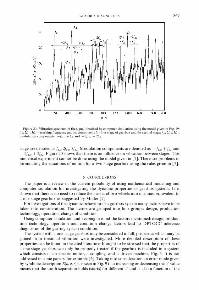
Figure 20. Vibration spectrum of the signal obtained by computer simulation using the model given in Fig. 19;fz1
; 2fz1
; 3fz1*meshing frequency and its components for "rst stage of gearbox and for second stage: f
z2; 2f
z2; 3f
z2;
modulation components: !fz2
; #fz2
and !2fz2
; #2fz2
.
869GEARBOX DIAGNOSTICS
stage are denoted as fz2
; 2fz2
; 3fz2
. Modulation components are denoted as !fz2
;#fz2
and!2f
z2;#2f
z2. Figure 20 shows that there is an in#uence on vibration between stages. This
numerical experiment cannot be done using the model given in [7]. There are problems informulating the equations of motion for a two-stage gearbox using the rules given in [7].
6. CONCLUSIONS
The paper is a review of the current possibility of using mathematical modelling andcomputer simulation for investigating the dynamic properties of gearbox systems. It isshown that there is no need to reduce the inertia of two wheels into one mass equivalent toa one-stage gearbox as suggested by Muller [7].
For investigations of the dynamic behaviour of a gearbox system many factors have to betaken into consideration. The factors are grouped into four groups: design, productiontechnology, operation, change of condition.
Using computer simulation and keeping in mind the factors mentioned: design, produc-tion technology, operation and condition change factors lead to DPTOCC inferencediagnostics of the gearing system condition.
The system with a one-stage gearbox may be considered in full; properties which may begained from torsional vibration were investigated. More detailed description of theseproperties can be found in the cited literature. It ought to be stressed that the properties ofa one-stage gearbox can only be properly treated if the gearbox is included in a systemwhich consists of an electric motor, a coupling, and a driven machine, Fig. 3. It is notaddressed in some papers, for example [6]. Taking into consideration an error mode givenby symbolic description E(a, e, r) it is seen in Fig. 9 that increasing or decreasing the &e' valuemeans that the tooth separation holds (starts) for di!erent &e' and is also a function of the
870 W. BARTELMUS
a parameter. Figure 12 gives evidence that the r parameter, describing the range of randomchange of e value, also has an in#uence on the dynamic properties. Besides this dramaticin#uence, the clutch sti!ness also has an in#uence. Comparing results of computer simula-tion to results of measurements on real gearboxes (see Figs 5, 6 and 7, 10 and furthercompare 10 to 11) one can come to the conclusion of their good consistency. It ought to bementioned that in models given in [1}4] and [6] the coupling damping is not taken intoconsideration.
Summing up, the inter-tooth forces increase dramatically in unstable conditions. A one-stage gear system can operate under resonance conditions and is unstable when the gearboxsystem's mesh frequency is equal to its natural frequency. In such conditions the inter-toothforces are two times or more greater than the rated forces. Computer simulations reveal thatconditions similar to those occurring at resonance may result as errors (pitting, scu$ng oftooth #anks and failure of bearings) increase during the service of a gearbox system. It isshown that a #exible coupling and an error mode random parameter have an in#uence ongearbox stability (tooth separation).
Figures 13}16 show a dramatic in#uence of tooth fracture on the vibration spectrumgenerated by gearing. This is also presented in [6].
Propositions for further models with lateral and torsional vibration are given. It is hopedthat phenomena connected with inter-tooth friction will be investigated using the modelwith lateral vibration, Fig. 18. The model for a system with a two-stage gearbox, taking intoconsideration torsional vibration, is also given in Fig. 19. Using this model the in#uence ofvibration from a second stage on the vibration of the "rst stage is given by showingmodulation of the meshing components of the "rst stage.
ACKNOWLEDGMENTS
Part of the results presented in the paper were obtained within a grant supported by thePolish Scienti"c Committee, Grant No. 7 T0TB 017 18.
REFERENCES
1. S. M. WANG 1974 ¹ransactions of the ASME Journal of Engineering for Industry. Analysis ofnonlinear transient motion of a geared torsional. February p. 51}59.
2. W. D. MARK 1978 Journal of Acoustical Society of America 63, 1409}1430. Analysis of thevibratory excitation of gear systems: basic theory.
3. P. VELEX and M. MAATAR 1996 Journal of Sound and <ibration 191, 629}660. A mathematicalmodel for analysing the in#uence of shape deviations and mounting errors on gear dynamicbehaviour.
4. J. D. SMITH 1998 Proceedings of the Institute of Mechanical Engineers Part C 212, 217}223.Modelling the dynamics of misaligned helical gears with loss of contact.
5. S. DU, R. B. RANDALL and D. W. KELLY 1998 Proceedings of the Institute of Mechanical EngineersPart C: Journal of Mechanical Engineering Science 212, 287}297. Modelling of spur gear meshsti!ness and static transmission error.
6. S. P. YAO and P. D. MCFADDEN 2000 Conference Proceedings, France, 555}564. Study ofmodelling for monitoring of gearbox vibration.
7. L. MULLER 1986 Gearbox Dynamics Warsaw: WNT (in Polish).8. J. RY 1977 Ze. Naukowe Politechniki Krakowskiej, No. 6. Static and dynamic analysis of load for
gearboxes (in Polish).9. A. WILK 1981 Ze. Naukowe Politechniki 1 skiej, No. 679, Gliwice. In#uence of technology and
design parameters to spur gear dynamic (in Polish).10. Z. DABROWSKI 1992 Machine Dynamics Problems, Vol. 4. Warsaw University of Technology. The
evaluation of the vibroacoustic activity for needs of constructing and use of machines.
871GEARBOX DIAGNOSTICS
11. E. Z. DABROWSKI, S. RADKOWSKI and A. WILK (eds) 2000 Gearbox Dynamic Investigations andSimulations for Operation Orientated Design Warsaw}Katowice, Radom 2000 (in Polish).
12. W. BARTELMUS 1994 Conference proceedings Condition Monitoring '94 Swansea, ;.K., 184}201.Swansea, UK: Pineridge Press. Computer simulation of vibration generated by meshing oftoothed wheel for aiding diagnostics of gearboxes.
13. W. BARTELMUS 1996 Proceedings of 9th International Congress COMADEM 96, She.eld, July51}61. Diagnostic symptoms of unstability of gear systems investigated by computer simulation.
14. W. BARTELMUS 1996 Proceedings of XI< IMEKO=orld Congress, Tampere, Finland, 126}131.Visualisation of vibration signal generated by gearing obtained by computer simulation.
15. W. BARTELMUS 1997 Proceedings of 10th International Congress COMADEM 97, Espoo, Finland,58}67. In#uence of random outer load and random gearing faults on vibration diagnostic signalsgenerated by gearbox systems.
16. W. BARTELMUS 1998, 1999 Proceedings of ¹he 7th International Symposium on ¹ransport Phe-nomena and Dynamics of Rotating Machinery, Honolulu, Hawaii, U.S.A.: 22}26 February Interna-tional Journal of Rotating Machinery 5, pp. 203}218. Transformation of gear inter teeth forces intoacceleration and velocity.
17. W. BARTELMUS 1998 Proceedings of ¹he 2nd International Conference, Planned MaintenanceReliability and Quality, ;niversity of Oxford, England, 12}15. New gear condition measure fromdiagnostic vibration signal evaluation.
18. W. BARTELMUS and R. ZIMROZ 2000 Proceedings of ¹hird International Conference on Quality,Reliability and Maintenance, Oxford ;.K. Vibration spectrum generated by gearing obtained bymodelling and computer simulation.
19. W. BARTELMUS 2000 Condition Monitoring & Diagnostic Engineering Management, vol. 3, No. 4,pp. 961}970. U.K.: COMADEM International. Mathematical modelling of gearbox vibration forfault detection.
20. W. BARTELMUS 1998 Condition Monitoring of Open Cast Mining Machinery. Poland: 1sk,Katowice (in Polish). Being prepared for publication by COMADEM UK (in English).
21. W. BARTELMUS 2000 Proceedings of COMADEM 2000, Houston, ;.S.A., 961}970. Progress inmathematical modelling and computer simulation for supporting gearbox diagnostic inference.
22. W. BARTELMUS 2001 Journal of ¹heoretical Gearbox Dynamic Modelling and Applied MechanicsVol. 39, No. 4, 1}11.
23. H. RETTIG 1977 Ant. Antriebstechnik 16, 655}663. Innere Dynamische Zusatzkrafte bei Zahanad-getrieben.
24. A. J. PENTER 1991 Proceedings of an International Conference on Condition Monitoring, 79}96.Erding, Germany: Pineridge Press. A practical diagnostic monitoring system.
25. J. TUMA, R. KUBENA and V. NYKL 1994 Proceedings of International Gearing Conference,Newcastle. Assessment of gear quality considering the time domain analysis of noise and vibrationsignals.
26. W. BARTELMUS 1988 Proceedings of the Second International Symposium on Continuous SurfaceMining, Austin, ¹exas, October, 131}144. Rotterdam, Brook"eled: A. A. Balkema. Diagnostic ofbevel and cylindrical gears in surface mines.
27. W. BARTELMUS 1992 Machine <ibration, vol. 1, pp. 178}189. London: Springer-Verlag. Vibrationcondition monitoring of gearboxes.
28. A. WILK, Z. NIEDZIELA and B. |AZARZ 1989 Software for Gearing Sti!ness Assessment for Spur,Helical and Herringbone Gearing (unpublished) Warsaw: Katowice.
29. L. SIWICKI 1992 Manual for CSSP. Warsaw (in Polish).30. P. ABNO 2001 Manual for CSSP for =INDO=S, v.1.01 Wroclaw (in Polish).