Embed Size (px)
Citation preview

httpcorepulsedewwwsystemfileswiipcpdf
httpwwwwiiliorgindexphpHowToBlueSoleil
httpwwwsevengamesdepc_konsolenextrasartikelwii_188455
httpwwwwiiliorgindexphpMain_Page
Godbersen GlovePIE PPjoy Wii (GlovePIE_PPjoydoc 14062007) 274
Wii Remote httpenwikipediaorgwikiWiimote
From Wikipedia the free encyclopedia (Redirected from Wiimote) Jump to navigation search
Wii Remote with attached strap
The Wii Remote also nicknamed Wiimote is the primary controller for Nintendos Wii console The main features of the Wii Remote are its motion sensing capability which allows the user to interact with and manipulate items on screen via movement and pointing and its expandability through the use of attachments
The Wii Remote was announced at the Tokyo Game Show on September 17 2005 It has since received much attention due to its unique features and the contrast between it and typical gaming controllers It has also gained significant attention from hackers reprogramming it to control non Wii-related devices through Wii homebrew[1]
Contents
bull 1 Design o 11 Colors o 12 Strap
bull 2 Functionality o 21 Sensing o 22 Controller feedbacko 23 Memory o 24 Power source
bull 3 Controller expansions o 31 Nunchuk o 32 Classic Controller o 33 Zapper
bull 4 Accessories o 41 Glove kits
Godbersen GlovePIE PPjoy Wii (GlovePIE_PPjoydoc 14062007) 374
o 42 Steering wheels o 43 Sword attachment o 44 Sports packages o 45 Chargers
bull 5 Home Menu o 51 Buttons
bull 6 Reception bull 7 References bull 8 External links
Design
Wikinews has news related to Nintendo unveils controller for Revolution console
The Wii Remote assumes a one-handed remote control-based design instead of the traditional gamepad controllers of current gaming consoles This was done to make motion sensitivity more intuitive as a remote design is fitted perfectly for pointing and in part to help the console appeal to a broader audience that includes non-gamers The controller communicates wirelessly with the console via short-range Bluetooth radio with which it is possible to operate up to four controllers as far as 10 meters (approx 30ft) away from the console However to utilize pointer functionality the Wii Remote must be used within five meters (approx 16ft) of the Sensor Bar[5][6] The controllers symmetrical design allows it to be used ambidextrously meaning it can be used by either the right hand or the left hand The Wii Remote can also be turned horizontally and used like a FamicomNES controller or in some cases (like Excite Truck and Sonic and the Secret Rings) a steering wheel It is also possible to play a single player game with a Wii Remote in each hand as in the Shooting Range game contained in Wii Play
At E3 2006 a few minor changes were made to the controller from the design presented at the Game Developers Conference The controller was made slightly longer and a speaker was added to the face beneath the center row of buttons The B button became more curved resembling a trigger The Start and Select buttons were changed to plus + and minus ndash and the b and a buttons were changed to 1 and 2 to differentiate them from the A and B buttons Also the symbol on the Home button was changed from a blue dot to a shape resembling a homehouse the shape of the power button was circular rather than rectangular and the blue LEDs indicating player number are now represented with small dots instead of Arabic numerals with 1 being bull 2 being bullbull 3 being bullbullbull and 4 being bullbullbullbull The Nintendo logo at the bottom of the controller face was replaced with the Wii logo Also the expansion port was redesigned with expansion plugs featuring a smaller snap-on design[7]
The blue LEDs also show how much battery power remains on the Wii Remote Four of the LEDs flash when it is at or near full power Three lights flash when it is at 75 two lights when at 50 and one light flashes when there is 25 or less power remaining
Godbersen GlovePIE PPjoy Wii (Glov
ePIE_PPjoydoc 14062007) 474
Functionality
Sensing
Sensor Bar highlighting IR LEDs
The Wii Remote has the ability to sense both rotational orientation and translational acceleration along three dimensional axes[19] through the use of an Analog Devices ADXL330 accelerometer in the Wii Remote[5][20] The Wii Remote also features a PixArt optical sensor allowing it to determine where the Wii Remote is pointing[21]
Unlike a light gun that senses light from a television screen the Wii Remote senses light from the consoles Sensor Bar which allows consistent usage regardless of a televisions type or size The Sensor Bar is about 20 cm in length and features ten infrared LEDs with five LEDs being arranged at each end of the bar[22] In each group of five LEDs the LED farthest away from the center is pointed slightly away from the center the LED closest to the center is pointed slightly toward the center while the three LEDs between them are pointed straight forward and grouped together The Sensor Bars cable is 353 cm (11 ft 7 in) in length The bar may be placed above or below the television and should be centered If placed above the sensor should be in line with the front of the television and if placed below should be in line with the front of the surface the television is placed on It is not necessary to point directly at the Sensor Bar but pointing significantly away from the bar will disrupt position-sensing ability due to the limited viewing angle of the Wii Remote
The use of the Sensor Bar allows the Wii Remote to be used as an accurate pointing device up to 5 meters (approx 16 ft) away from the bar[6] The Wii Remotes image sensor[21] is used to locate the Sensor Bars points of light in the Wii Remotes field of view The known real-world dimensions of the spacing between the LEDs on the bar allows the Wii Remote to calculate its distance from the bar[23] while the tilt and rotation of the Wii Remote with respect to the ground can be calculated from the relative angle of the Sensor Bar (which sees the bar as two bright dots) and the data sensed by the accelerometers Furthermore the game can be programmed to sense whether the image sensors are covered which is demonstrated in a minigame of Smooth Moves where if the player does not uncover the sensor the champagne bottle that the remote represents will not open
Godbersen GlovePIE PPjoy Wii (GlovePIE_PPjoydoc 14062007) 574 The Sensor Bar is required when the Wii Remote is controlling up-down left-right motion of a cursor or reticle on the TV screen to point to menu options or objects such as enemies in first person shooters Because the Sensor Bar also allows the Wii Remote to calculate the distance between the Wii Remote and the Sensor Bar[24] the Wii Remote can also control slow forward-backward motion of an object in a 3-dimensional game[25] Rapid forward-backward motion such as punching in a boxing game is controlled by the acceleration sensors Using these acceleration sensors (acting as tilt sensors) the Wii Remote can also control rotation of a cursor or other objects[26]
The use of an infrared sensor to detect position can cause some detection problems when other infrared sources are around such as incandescent light bulbs or candles This can be easily alleviated by using fluorescent lights around the Wii which emit little to no infrared light[27] Innovative users have used other sources of IR light as Sensor Bar substitutes such as a pair of flashlights and a pair of candles[28] Such substitutes for the Sensor Bar illustrate the fact that a pair of non-moving lights provide continuous calibration of the direction that the Wii Remote is pointing and its physical location relative to the light sources There is no way to calibrate the position of the cursor relative to where the user is pointing the controller without the two stable reference sources of light provided by the Sensor Bar or substitutes
The position and motion tracking of the Wii Remote allows the player to mimic actual game actions such as swinging a sword or aiming a gun instead of simply pushing buttons An early marketing video showed actors miming actions such as fishing cooking drumming conducting a string quartet shooting a gun sword fighting and performing dental surgery[29]
Controller feedback
The Wii Remote also provides basic audio and rumble functionality At the 2006 E3 press conference it was revealed that the Wii Remote has its own independent speaker on the face of the unit This was demonstrated by a developer as he strung and shot a bow in The Legend of Zelda Twilight Princess The sound from both the Wii Remote and television was altered as the bow shot to give the impression of the arrow traveling away from the player Another example of its use is in Red Steels Killer match where the players will receive their objective through the Wii Remote The speaker has been noted for being low quality and small emitting poor quality sound especially at high volumes[30] although the volume can be changed with the Home button and selecting the corresponding controller icon at the bottom of the screen[31]
Memory
The Wii Remote contains a 16 KiB EEPROM chip from which a section of 6 kilobytes can be freely read and written by the host[27][32] Part of this memory is available to store up to 10 Mii avatars which can be transported for use with another Wii console At least 4000 bytes are available and unused before the Mii data which may be used in future games
Power source
The Wii Remote uses two AA batteries as a power source which can power a Wii Remote for 60 hours using only the accelerometer functionality and 30 hours using both accelerometer and pointer functionality[27] An official direct recharging option for the Wii Remote has not
Godbersen GlovePIE PPjoy Wii (GlovePIE_PPjoydoc 14062007) 674 yet been revealed but various third-party manufacturers market charging solutions for the controller (see section on chargers) According to an interview with Nintendo industrial designer Lance Barr limitations of the Wii Remotes expansion port make it unlikely that it will be used for internal battery charging[33] Although the Wii manual discourages the use of rechargeable batteries Nintendos support website has indicated that NiMH rechargeable batteries may be used[34] A 3300uF capacitor provides a temporary source of power during quick movements of the Wii Remote when connection to the batteries may be temporarily interupted[35]
Controller expansions
The Wii Remote also features an expansion port at the bottom which allows various functional attachments to be added to the controller The following attachments are currently known
Nunchuk
The Nunchuk (left) plugged into a pre-release model of the Wii Remote as shown at E3 2006
The Nunchuk is the first controller attachment Nintendo revealed for the Wii Remote at the 2005 Tokyo Game Show It connects to the Wii Remote via a long cord and its appearance while attached resembles the nunchaku It features an analog stick similar to the one found on the Nintendo GameCube controller and two trigger buttons (a last minute modification changed the two triggers to one trigger and a C button as described below) It works in tandem with the main controller in many games Like the Wii Remote the Nunchuk also provides accelerometer for three axis motion-sensing and tilting but without a speaker a rumble function or a pointer function[6][36][37]
A Nunchuk comes bundled with the Wii console[38][39] Separate Nunchuks retail in Japan for JPyen1800[2] in the United States for US$1999[3] in Canada for CA$2499 in Europe for euro19[4] and in the United Kingdom for pound14[4]
Godbersen GlovePIE PPjoy Wii (GlovePIE_PPjoydoc 14062007) 774 The two shoulder buttons formerly named Z1 and Z2 respectively had been reshaped and renamed since the Game Developers Conference The circular top shoulder button now called C is much smaller than the lower rectangular shoulder button now called Z The C button is oval shaped while the Z button is square[40]
The body of the Nunchuk measures 113 mm long 382 mm wide and 375 mm thick[5] The cord for the Nunchuk is approximately three and a half to four feet long In the original design of the Nunchuk it was much longer The connection port was also larger[1]
Product images and an Overstockcom listing indicate that game accessory manufacturer Intec is releasing a third-party Nunchuk for the Wii Remote This is the first third-party expansion to be discovered for the Wii Remote[41]
Classic Controller
The Classic Controller connected to the Wii Remote
During E3 2006 Nintendo introduced a Classic Controller which plugs into the Wii Remote via a cord similar to the Nunchuk[5] The Classic Controllers look is roughly modelled on the controller scheme used for the SNES but with two additional analog sticks and two extra shoulder buttons (the ZL and ZR buttons used to replicate the Z button found on the Nintendo 64s controller) The overall configuration is similar to that of other major seventh generation console controllers
The Classic Controllers cord comes out the bottom instead of the top of the controller (a configuration shared by the Dreamcast controller) The Classic Controller contains slots on its backside opened via a rectangular button at the top of the controller presumably for clipping the controller to something else[42] The purpose for these slots remains undisclosed[43] but it is commonly believed to be used with a special clip that attaches the Wii Remote to the Classic Controller enabling it to have abilities similar to the PlayStation 3 controller as well as provide similar controls to the Nintendo 64 controller Nyko had announced they are releasing such a clip in addition to a grip shell and a place to store the cable[44] The body of the Classic Controller measures 657 mm tall 1357 mm wide and 26 mm thick[5] The Classic Controller does not feature an accelerometer or a rumble function
The Classic Controller cannot be used to play Nintendo GameCube games According to the Nintendo Online Shop the Classic Controller can only be used with Virtual Console games (although some Wii games such as Dragon Ball Z Budokai Tenkaichi 2 and Super Smash Bros Brawl can be played with it) The Nintendo GameCube controller can be used instead of the Classic Controller for playing most Virtual Console games When in the Wii Menu the left analog stick takes control of the cursor when the Wii Remote is not pointed at the screen The Classic Controller can navigate through the Message Board Settings menus and Shop
Godbersen GlovePIE PPjoy Wii (GlovePIE_PPjoydoc 14062007) 874 Channel However it becomes inactive on the Mii Photo Forecast News Internet and Everybody Votes channels
Nintendo had previously announced a controller shell which resembled a traditional game controller often referred to as a classic-style expansion controller[45] As described at the time the Wii Remote would fit inside the shell allowing gamers to play games using a traditional-style gamepad while allowing use of the remotersquos motion sensing capability It would allow controls similar to a PlayStation 3 controller According to Satoru Iwata it would be meant for playing the existing games Virtual Console games and multi-platform games[46]
The Classic Controller features two analog sticks a D-pad face buttons labeled a b x and y analog shoulder buttons labeled L and R and two Z buttons (labeled ZL and ZR) next to the L and R buttons respectively It also has a set of - Home and + buttons like those on the Wii Remote with the - and + buttons labeled Select and Start respectively
Classic Controllers retail in Japan for JPyen1800[2] in the United States for US$1999[47] in Canada for CA$2499 in Europe for euro19[4] in Australia for AU$2999 and in the United Kingdom for pound15[4]
Zapper
Zapper shell with the Wii Remote
Nintendo has showcased a gun shell peripheral concept design for the Wii Remote known as Zapper The name is a throwback to the NES Zapper light gun for the Nintendo Entertainment System The Wii Remote slots into the gun barrel of the shell[48] The shell features a trigger hole as well as an analog stick on the top of the handle[49] making it similar to the Nunchuk attachment but without the accelerometer and the second button Nintendo has not announced whether the Zapper will be produced for sale
In early April video game retailer GameStop listed a Wii Blaster peripheral on its website with a release date of May 1 2007 Originally listed without a specified manufacturer the Wii Blaster had been speculated to be the Zapper[2] but has since been indicated to be produced by third party accessories manufacturer Core Gamer According to GameStop on May 5 2007 the Wii Blaster release date has changed to June 26 2007 and is available for pre-ordering[50]
While not technically an expansion details on an aesthetic gun accessory for the Wii Remote and Nunchuk named the Sharp Shooter have been released by third-party manufacturer Joytech[51] In this accessory the Wii Remote is housed in the gun barrel The Nunchuk is fitted into the handle so that the Nunchuk triggers serve as gun triggers
Godbersen GlovePIE PPjoy Wii (GlovePIE_PPjoydoc 14062007) 974
Accessories While few third-party controller expansions have been revealed many aesthetic and ergonomic accessories have been developed for the Wii Remote including texturized covers and extensions shaped like tennis rackets baseball bats and golf clubs[52]
Glove kits
Glove kits have been produced that allow a better grip on the Wii Remote These are available in several colors some of which glow in the dark or change hue from the heat of the players hand
Steering wheels
Introduced by Ubisoft the Wii Steering Wheel is an accessory shell for the Wii Remote developed by Thrustmaster and is bundled with certain games such as Monster 4x4 World Circuit and GT Pro Series[53] The accessory which is only for aestheticergonomic enhancement is meant for driving-style gameplay in which the Wii Remote would be held lengthwise in a two-handed gamepad orientation steering the subject by tilting the controller The Wii Steering Wheel is also sold separately for US$1699 Since the Wii Steering Wheel was revealed other similarly designed steering wheel accessories have been produced including the Wii Racing Wheel by Intec[3]
Sword attachment
A sword and shield attachment has been released by ASiD These accessories are simply shells and do not provide any other functional purpose The kit comes with a sword a shield and a knife (more of a curved sword resembling a scimitar) all in the monochromatic white design of the Wii hardware The Wii Remote slides into the handle of the sword (or knife) and the Nunchuk clips into the back of the shield
Sports packages
The Wii Sports pack was released by GameStop in the United States and Logic3 in Europe It includes a baseball bat a golf club and a tennis racket It is very similar to the sword accessory and attaches to the Wii Remote to allow a more realistic experience with Wii Sports
The boxing gloves are a seperate accessory to the Wii Sports pack With those the player can put the Wii Remote and Nunchuk inside each glove underneath where one slips in hands The Nunchuk is assigned to the left glove while the Wii Remote is right In this way one can punch like an actual boxer instead of jabbing the controllers away from oneself
Chargers
While Nintendo does not currently offer a rechargeable option for the Wii Remote recharging systems have been developed by various third-party peripheral companies Nyko sells a direct-charging system for two Wii Remote units which is powered using an AC power adapter and uses a special battery pack and a cover with electrical contacts for charging and
Godbersen GlovePIE PPjoy Wii (GlovePIE_PPjoydoc 14062007) 1074 silicon texturing to add grip Nyko prices the system at US$2999[54] Another two-controller charging system sold by Joytech is powered through a USB connection which allows the unit to charge the Wii Remote through the Wii console Like the Nyko charging station the Joytech system includes two sets of special battery packs and covers with electrical contacts for charging The Joytech station features extensions on both sides for holding Nunchuks Joytech prices the system at US$39[55] Brando Workshop offers a USB-powered one-controller charging system with a combination charging standNunchuk cradle[4] While not a direct-recharging system like the others the Thrustmaster T-Charge NW combines a organizerstorage system for a Wii Remote and Nunchuk with a two-cell AA battery charger and includes a set of unobtrusive grips[56]
Home Menu
Accessed with the Wii Remotes home button the Home Menu displays information about the controller(s) currently being used and allows the user to configure certain options At the bottom of the menu screen the battery life of all connected controllers is displayed Below that is a bar labelled Wii Remote Settings Selecting it brings you to an options screen where you can control the audio output volume force feedback and recalibrate the controller
Buttons
Depending on when the Home Menu is accessed there will be a different amount of buttons displayed
Wii Menu No matter when the menu is accessed the Wii Menu button will always be present Selecting this will bring back the Wii Menu where one can choose another channel
Reset During gameplay the Reset button is also shown This allows the user to go back to the games title screen However all unsaved data is lost so it is wise to save game progress before resetting
Operations Guide On Wii Menu channels including the News Channel Forecast Channel Everybody Votes Channel Internet Channel and Virtual Console titles the Operations Guide button will appear on the Home Menu It provides brief explanations on the currently open application
Reception Overall reception to the Wii Remote has changed over time The control styles provided by the controller were met with praise at its first public exhibition at E3[57] Since then comments have been noted by the press on its functionality Matt Wales of IGN UK highlighted the aiming and precision of Red Steel and stated Taking down swathes of enemies with nothing more than a twitch of the wrist proves immensely satisfying and more importantly incredibly involving[58]
Other publications have noted specific complaints regarding control GameSpot expressed that some motions in Cooking Mama Cook Off failed to transmit or meet expectation during gameplay[59] Similar observations were made on other titles made available during the Wii
Godbersen GlovePIE PPjoy Wii (GlovePIE_PPjoydoc 14062007) 1174 launch period ComputerAndVideoGamescom reported that Most prominent is the first batch of games many of which do a better job at exposing the obstacles of full motion control rather than the benefitsRed Steel is twitchy and occasionally clumsy Need For Speedis near unplayable Far Cry got it all wrong and the motion control in Marvel Ultimate Alliance just feels tacked on[60]
The overall situtation was described by Joystiq thusly Over the months since launch the unpredictable Wii Remote has led to a maddening dichotomy Some games are too easy while others are too hard -- for all the wrong reasonsGamers who crave a deeper challenge have to settle for battling incomprehensible controls[61] Critics felt that fault was largely attributed to the developers lack of experience with the Wii Remote Jeremy Parish of EGM compared the initial phase of control implementation to that of the Nintendo DS[62] Matt Casamassina of IGN also presumed that the first generation of Wii games were of an experimental stage and that potential for refinement had yet to be exploited[63]
Later-released titles have seen mixed reactions in terms of control Of Tiger Woods PGA Tour 07 from EA Games Matthew Kato of Game Informer stated that the controller has a hard time detecting your backswing Thus itrsquos harder to control There were even times the game putted for me by accident[64] A GamePro review for Medal of Honor Vanguard offers that the title is an encouraging sign that developers are finally starting to work out the kinks and quirks of the Wii Remote[65]
References
1 ^ Jamin Brophy-Warren Magic Wand How Hackers Make Use Of Their Wii-motes Wall Street Journal April 28 2007
2 ^ a b c Japanese Conference Updates DONE N-Sider Retrieved on 2006-12-24 3 ^ a b Matt Casamassina Live from New York Were at Nintendos Wii event Live
updates begin now IGN Retrieved on 2006-12-24 4 ^ a b c d e f Wii European launch details announced Nintendo Retrieved on 2006-12-
24 5 ^ a b c d e f (Japanese) - Nintendo Company Ltd Retrieved on
2006-09-14 6 ^ a b c Nintendo Wii - Hardware Information Nintendo of America Retrieved on
2006-05-09 7 ^ wwwdestructoidcomnintendo-wiimote-change-before-after-puberty Retrieved on
2007-03-19 8 ^ httpmediawiiigncommedia821821973vid_1492011html 9 ^ httpmediacubeigncomarticles651651334vids_1html 10 ^ IGN Snaps Photos of Black Wii at THQ Event Then Takes Them Down Play
Feed Retrieved on 2006-12-24 11 ^ Wishnov Jason (2006-11-27) Fancy Wii skins Nintendo Fan Boy Retrieved on
2006-12-24 12 ^ Summa Robert New photos from THQs Wii event - update 1 Retrieved on 2007-
02-24 13 ^ Gantayat Anoop (2006-09-14) Wii Quotables IGN Retrieved on 2007-02-24 14 ^ Broken Wii Controller (video) IGN Retrieved on 2007-02-24 15 ^ Customer Service gt Wii gt Safety Information Nintendo Retrieved on 2007-02-24
Godbersen GlovePIE PPjoy Wii (GlovePIE_PPjoydoc 14062007) 1274
16 ^ Sliwinski Alexander (2006-12-08) Jumpin jinkies new Wii straps joystiqcom Retrieved on 2007-02-24
17 ^ Nintendo Issue Replacement Wii Wrist Straps Official Nintendo Magazine (2006-12-15) Retrieved on 2007-02-24
18 ^ Nintendo of America Initiates Replacement Program for Wrist Straps Used with Controllers for the Wii Video Game System US Consumer Product Safety Commission (2006-12-15) Retrieved on 2007-02-24
19 ^ Will Wii Rock You p 3 thinkdigitcom (2007) Retrieved on 2007-03-23 20 ^ Wisniowski Howard (2006-05-09) Analog Devices And Nintendo Collaboration
Drives Video Game Innovation With iMEMS Motion Signal Processing Technology Analog Devices Inc Retrieved on 2006-05-10
21 ^ a b Castaneda Karl (2006-05-13) Nintendo and PixArt Team Up Retrieved on 2007-02-24
22 ^ Troubleshooting the Wii Remote amp Sensor Bar Nintendo Retrieved on 2007-02-24 23 ^ Nintendo patent application 20070060384 Figure 16 and paragraph 0115 24 ^ Nintendo patent application 20070060384 Figure 16 and paragraph 0115 25 ^ Termed Pushing or Pulling in the Wii Operations Manual System Setup page 25 26 ^ Termed Twisting in the Wii Operations Manual System Setup page 25 27 ^ a b c Casamassina Matt (2006-07-14) Wii Controllers Unlocking the Secrets IGN
Retrieved on 2006-07-14 28 ^ Using two candles as a Wii Sensor Bar replacement YouTube Retrieved on 2006-
09-24 29 ^ TGS 2005 Revolution Teaser Video (video) IGN Retrieved on 2006-03-16 30 ^ Gerstmann Jeff (2006-12-12) The Legend of Zelda Twilight Princess CNET 31 ^ James Sander-Cederlof (2007-02-17) Wii Hardware FAQ GameFAQs Retrieved
on 2007-02-24 32 ^ Wii-mote Guts Spark Fun Electronics (2006-12-19) Retrieved on 2007-03-28 33 ^ Wii Controllers No Recharging Yet The Wiire Retrieved on 2006-05-11 34 ^ Set Up of the Wii Remote Nintendo Retrieved on 2006-11-26 35 ^ Wii-mote Guts Spark Fun Electronics Retrieved on 2006-12-19 36 ^ STMicroelectronics Drives Gaming Revolution with Nintendos Wii (2006-05-09)
Retrieved on 2006-05-12 37 ^ RUMOR The Wii Nunchuck rumble rumor surfaces again (2006-10-28)
Retrieved on 2006-11-16 38 ^ Wales Matt (2006-05-22) Reports claim Wii to slap down 16 at launch (English)
Computer and Video Games Retrieved on 2006-05-25 39 ^ Berghammer Billy (2006-06-02) The Ultimate in PR Spin The Perrin Kaplan
Interview Part Four (English) (WMV) Game Informer Retrieved on 2006-06-08 40 ^ Hands-On with the Wii Controller (2006-05-12) Retrieved on 2006-05-12 41 ^ Luke Plunkett (November 13 2006) Third-party Nunchuks inbound
KotakucomWii Nunchuk (Intec) Overstockcom (November 29 2006) 42 ^ Greenwald Will (2006-12-07) ZDNet Nintendo Wii Classic Controller Review amp
Comparison CNET Retrieved on 2007-01-01 43 ^ Sklens Mike (2006-05-10) News Article Wii Classic Controller Revealed
NintendoWorldReport Retrieved on 2006-05-11 44 ^ IGN preview Nyko Wii classic Controller shell IGN (2007-02-23) Retrieved on
2007-02-24
Godbersen GlovePIE PPjoy Wii (GlovePIE_PPjoydoc 14062007) 1374
45 ^ Gibson Ellie (2005-09-16) Jim Merrick Takes Control Eurogamer Retrieved on 2006-05-09
46 ^ 47 ^ Vore Bryan (2006-09-15) Wii Classic Controller And Video Cable Questions
Answered Game Informer Retrieved on 2007-02-24 48 ^ Miller Ross (2006-05-10) E3 The Wii Zapper prototype revealed Joystiq
Retrieved on 2006-05-11 49 ^ Bozon Mark (2006-05-10) E3 2006 Light Gun Shell Revealed IGN Retrieved on
2006-05-10 50 ^ httpwwwgamestopcomproductaspproduct5Fid=802669 51 ^ httpwwwgamingbitscomcontentview19332 52 ^ Captain (2006-11-17) Futuretronics unveils Wii Remote shell range Aussie-
Nintendocom Retrieved on 2007-02-24 53 ^ Casamassina Matt (2006-09-08) Interview GT Pro Series IGN Retrieved on
2007-02-24 54 ^ Sliwinski Alexander (2007-01-09) Nykos Wii-chargeable Station Joystiq
Retrieved on 2007-01-20 55 ^ Stern Zack (2006-12-19) Rechargeable Wii Remote Batteries and Dock in 2007
Joystiq Retrieved on 2007-01-20 56 ^ httpgearigncomarticles775775991p1html 57 ^ 2006 Winners Game Critics Awards Retrieved on 2006-08-13 58 ^ Red Steel UK Review IGN Retrieved on May 11 2007 59 ^ Cooking Mama Cook Off Review GameSpot Retrieved on May 7 2007 60 ^ Is the novelty of Wii wearing off ComputerAndVideoGamescom Retrieved on
May 8 2007 61 ^ Cooking Mama Cook Off highlights Wii Remote issues joystiqcom Retrieved on
May 8 2007 62 ^ Jeremy Parish Elebits review (January 2007) Electronic Gaming Monthly pp 64 63 ^ N-Query IGN Retrieved on May 8 2007 64 ^ TIGER ASKS FOR A MULLIGAN gameinformercom Retrieved on May 11 2007 65 ^ Review Medal of Honor Vanguard gameprocom Retrieved on May 11 2007
External links
bull Official Nintendo Site bull Official Wii Site bull Wii Controllers page bull Accessories page bull US Patent Application 20070049374
Godbersen GlovePIE PPjoy Wii (GlovePIE_PPjoydoc 14062007) 1474
Wiimote
httpwwwwiiliorgindexphpWiimote
This page is intended to be a technical guide to the Wii Remote For an excellent high-level overview of the Wii Remote (aka Wiimote) see the Wikipedia article New information and status updates should be posted to the talk page and will eventually be digested and summarized here For more info about the physical hardware be sure to check out the hardware page
Contents
bull 1 Communication o 11 HID Interface
bull 2 Inputs o 21 Buttons o 22 Motion Sensor o 23 Calibration
231 Calibration Data o 24 IR Sensor
bull 3 Outputs o 31 Player LEDs o 32 Rumble
bull 4 Speaker o 41 Initialization Sequence o 42 Speaker Configuration o 43 Sound Data Format
bull 5 Onboard Memory o 51 Flash Memory o 52 Control Registers o 53 Reading and Writing
531 Communication with the Nunchukbull 6 Expansion Port bull 7 Batteries bull 8 See Also
Communication
The Wiimote communicates with the Wii via a Bluetooth wireless link The Bluetooth controller is a Broadcom 2042 chip which is designed to be used with devices which follow the Bluetooth Human Interface Device (HID) standard such as keyboards and mice The Bluetooth HID is directly based upon the USB HID standard and much of the same documentation applies
Godbersen GlovePIE PPjoy Wii (GlovePIE_PPjoydoc 14062007) 1574 When queried with the Bluetooth Service Discovery Protocol (SDP) the Wiimote reports back a great deal of information listed at Wii_bluetooth_specsspd info In particular it reports
Name Nintendo RVL-CNT-01 Vendor ID 0x057e Product ID 0x0306
The Wiimote sends reports to the host with a maximum frequency of 100 reports per second
The Wiimote does not require any of the authentication or encryption features of the Bluetooth standard In order to interface with it one must first put the controller into discoverable mode by either pressing the 1 and 2 buttons at the same time or by pressing the red sync button under the battery cover Once in this mode the Wiimote can be queried by the Bluetooth HID driver on the host If the HID driver on the host does not connect to the Wiimote within 20 seconds the Wiimote will turn itself off Holding down the 1 and 2 buttons continuously will force the Wiimote to stay in discoverable mode without turning off This does not work with the sync button however When in discoverable mode the Player LEDs will blink The number that blink will correspond to the remaining battery life similar to the meter on the Wii home menu where of bars = of lights
HID Interface
The HID standard allows devices to be self-describing using a HID descriptor block This block includes an enumeration of reports that the device understands A report can be thought of similar to a network port assigned to a particular service Reports are unidirectional however and the HID descriptor lists for each port the direction (Input or Output) and the payload size for each port Like all Bluetooth HID devices the Wiimote reports its HID descriptor block when queried using the SDP protocol A human-readable version of the block is shown at Wii_bluetooth_specsHID_Descriptor and is summarized in the following table
Output Report
ID Payload
Size Known Functions
0x11 1 Player LEDs Force Feedback
0x12 2 Report type ID 0x13 1 IR Sensor Enable 0x14 1 Enable speaker 0x15 1 Controller status 0x16 21 Write data 0x17 6 Read data 0x18 21 Speaker data
Input Report
ID Payload
Size Known Functions
0x20 6 Expansion Port 0x21 21 Read data 0x22 4 Write data 0x30 2 Buttons only
0x31 5 Buttons | Motion Sensing Report
0x32 16 Buttons | Expansion Port | IR
0x33 17 Buttons | Motion Sensing
Godbersen GlovePIE PPjoy Wii (GlovePIE_PPjoydoc 14062007) 1674
0x19 1 Mute speaker
0x1a 1 IR Sensor Enable 2
Report
0x34 21 Buttons | Expansion Port | IR
0x35 21 Buttons | Motion Sensing Report | Expansion Port
0x36 21 Buttons | Expansion Port | IR
0x37 21 Buttons | Motion Sensing Report | Expansion Port
0x38 21 Buttons | Motion Sensing Report | IR
0x3d 21 Buttons | Expansion Port | IR
0x3e 21 Buttons | Motion Sensing Report | IR
0x3f 21 Buttons | Motion Sensing Report | IR
Note that Output refers to packets are sent from the host to the Wiimote and Input refers to packets that are sent from the Wiimote to the host For clarity the convention in this document is to show packets including the Bluetooth header (in parentheses) report ID (also called channel ID in some places) and payload as described in sections 73 and 74 of the Bluetooth HID specification Each byte is written out in hexadecimal without the 0x prefix separated by spaces For example
(a1) 30 00 00
is a DATA input packet (0xa1) on channel 0x30 with the two byte payload 0x00 0x00
It actually seems that Force Feedback is accessible through ALL output channels the same way
Note On some wii-motes IR wont start transmitting until a read-report 0x38 has been sent
Inputs
Buttons
There are 12 buttons on the Wiimote Four of them are arranged into a directional pad and the rest are spread over the controller
By default whenever a button is pressed or released a packet is sent to the host via HID input report 30H with a payload containing a 2-byte bitmask with the current state of all the buttons
Godbersen GlovePIE PPjoy Wii (GlovePIE_PPjoydoc 14062007) 1774 The button state also seems to be included in the first two bytes of all other input reports
Some of the bits in the first two bytes dont seem to be directly related to button presses and are somewhat unknown
For example when the A button is pressed this HID DATA input packet is received
(a1) 30 00 08
and when it is released this is packet received
(a1) 30 00 00
The bit assignments (in big endian order) for the buttons are
Button Number (dec) Value (hex) Two 1 0x0001 One 2 0x0002 B 3 0x0004 A 4 0x0008 Minus 5 0x0010 Unknown (motion reports) or Z Acceleration bit 6 (report 3E) or bit 2 (report 3F) 6 0x0020
X Acceleration LSB (motion reports) or Z Acceleration bit 7 (report 3E) or bit 3 (report 3F) 7 0x0040
Home 8 0x0080 Left 9 0x0100 Right 10 0x0200 Down 11 0x0400 Up 12 0x0800 Plus 13 0x1000 Y Acceleration LSB (motion reports) or Z Acceleration bit 4 (report 3E) or bit 0 (report 3F) 14 0x2000
Z Acceleration LSB (motion reports) or Z Acceleration bit 5 (report 3E) or bit 1 (report 3F) 15 0x4000
Unknown 16 0x8000
The power button is unusual in that it sends a disconnect request when held down instead of emitting a normal button code
Godbersen GlovePIE PPjoy Wii (GlovePIE_
PPjoydoc 14062007) 1874
Motion Sensor
Coordinate system used by Wiimote
The motion of the remote is sensed by a 3-axis linear accelerometer located slightly left of the large A button The integrated circuit is the ADXL330 (data sheet) manufactured by Analog Devices This device is physically rated to measure accelerations over a range of at least +- 3g with 10 sensitivity
Inside the chip is a small micro mechanical structure which is supported by springs built out of silicon Differential capacitance measurements allow the net displacement of the tiny mass to be converted to a voltage which is then digitized It is important to note that the sensor does not measure the acceleration of the Wiimote but rather the force exerted by the test mass on its supporting springs Due to the sign convention used this quantity is proportional to the net force exerted by the players hand on the Wiimote when holding it Thus at rest on a flat table the accelerometer reports vertical force of +g (the mass can be normalized away into the aribitrary units) and when dropped reports a force of nearly zero
The sensor uses a right-handed coordinate system with the positive X-axis to the left and the positive Z-axis pointing upward when the remote is held horizontally as shown in the diagram at the right Forces on each axis are digitized to 8 bit unsigned integers with the zero scale set to 0x80 Manufacturing and calibration defects of course cause some intrinsic zero offsets However the Earths gravitational field and a flat level surface upon which to rest the remote in principle allow any offsets or chip skew to be measured and calibrated away in software The calibration values are stored near the start of the Wiimotes flash RAM Decomposing the force measured by the sensor into rotation and linear components is tricky and discussed further on the Motion analysis page
Godbersen GlovePIE PPjoy Wii (GlovePIE_PPjoydoc 14062007) 1974 The Wiimote does not normally report motion sensor readings to the host but can be requested by sending SET_REPORT request to channel 0x12
(52) 12 00 31
The 3rd byte is a bitmask 0x01 turns on the rumble and 0x04 turns on continuous output If 0x04 is not set packets are only output when the values change (almost always when the motion sensor is enabled) If 0x04 is set values are output continuously In continuous mode the device will send data at 100 packages per second Its obvious when channelmode 0x30 is chosen which disables motion readback With byte3=0x04 the button values are output multiple times a second With byte3=0x00 they are output only when you press or release a button
The 4th byte specifies which HID channel to which log sensor output should be sent After receiving this command once the Wiimote will send back stream of DATA INPUT packets on the requested channelmode (0x31 in the above example) where in reports 0x31 0x33 0x35 and 0x37 the 5th 6th and 7th bytes contain the X Y and Z readings of the accelerometer A sample packet when the Wiimote is at rest face up on a table is
(a1) 31 40 20 86 8a a5
where 0x86 is the X-axis measurement 0x8a is the Y-axis measurement and 0xa5 is the Z-axis measurement The first two bytes of the payload 0x40 and 0x20 are the button values and some other bits These bits are important in reports 0x3E and 0x3F The button values are still in the same place and have the same meanings as in the Buttons section
Other channels can be selected for motion sensor reports including 0x31 0x33 0x35 0x37 0x3e and 0x3f If either 0x3e or 0x3f are selected then sensor readings will alternate between the two channels 0x3E contains the X Acceleration in the third byte of the payload wheras 0x3F contains the Y Acceleration in the third byte of the payload The Z Acceleration is stored in the button flags as shown in the button table above 0x3E and 0x3F use the remaining 18 bytes for what we think is IR data
The length of the report payload will depend upon the channel as show in the table in HID Interface section Channels which have payloads longer than needed for the motion sensor will apparently pad the end of the packet with 0xff bytes
(a1) 33 40 00 86 8a a5 ff ff ff ff ff ff ff ff ff ff ff ff ff
Motion sensor reports can be stopped by setting the output channel to 0x30
(52) 12 00 30
It seems that the channel mode is actually a mode selection bitmask Button output is always enabled Mode 0x30 is just buttons 0x31 is motion sensor 0x32 is IR camera () and 0x33 is both IR camera and motion sensor The two sets of data are tacked onto each other first the button values then the three motion sensor bytes then the camera bytes Other modes seem to include motion data and or IR data in different ways
Godbersen GlovePIE PPjoy Wii (GlovePIE_PPjoydoc 14062007) 2074 Calibration
The zero points and gravity values for the three accelerometer axes are stored near the start of the Wiimotes flash memory
Calibration Data
Calibration data for the onboard accelerometer is stored in the Wiimotes memory starting at address 0x16 This information is repeated at 0x20
0x16 zero point for X axis 0x17 zero point for Y axis 0x18 zero point for Z axis 0x19 unknown 0x1A +1G point for X axis 0x1B +1G point for Y axis 0x1C +1G point for Z axis 0x1D unknown 0x1E-0x1F checksum
IR Sensor
During RampD Nintendo discovered the motion sensors were not accurate enough to use the remote to control an on-screen cursor To correct this they augmented the remote with an infrared image sensor on the front designed to locate two IR beacons within the controllers field of view The beacons are housed within a device misleadingly called the Sensor Bar
These two sources of IR light are tracked by a PixArt sensor in the front of the Wiimote housing By tracking the locations of these two points in the sensors 2D field of view the system can derive more accurate pointing information Not much is known about this feature yet but circumstantial evidence from the NintendoPixArt press release suggests that Nintendo is using a PixArt System-on-a-Chip to process the images on-board the Wiimote and sends the minimum information needed for tracking back to the base unit Transmitting full 2D images constantly would require a prohibitive amount of bandwidth especially when multiple remotes are in use
Wiimote detects and transfers up to four IR hotspots back to the host Various amounts of data can be requested from position values only position and size to position size and pixel value The amount of different configurations are quite numerous and also ties in with the connected peripheral device
Communications with the camera module is performed via an I2C bus (or other 2-wire wired-or bidirectional serial bus) Pins 5 and 6 of the camera (see silkscreen for pin s) are the clock and data respectively The bit rate is slightly less than 400kbaud These signals are also available at TP101 (data) down between the inductors and TP26 (clock) right next to the B button pad (under the B button housing) The broadcom chip and camera are the only two devices on this bus When the camera is active it sends data at 100Hz to the broadcom chip
Godbersen GlovePIE PPjoy Wii (GlovePIE_PPjoydoc 14062007) 2174 Output format EXP is three bytes per dot recognized Bytes 0 and 1 are X and Y byte 2 is the MSBs of X and Y and a size value In binary
xxxxxxxx yyyyyyyy yyxxssss
No dot is indicated by 0xff data This means you will not see any change in the output data even if you did do all the initialization correctly unless you actually point the Wiimote at a (powered) sensor bar
Output format for FULL is unknown but we know the data is interleaved Data sent to report 0x3e contains the data for the first two dots recognized data sent to 0x3f contains the data for the next two dots recognized if any
Note that the original hidd patch has trouble with 0x00 bytes in commands Make sure youre sending the right data
It is beneficial to add a slight pause (1100 sec) between sends when setting IR mode to let the remote keep up Without these pauses the remote appears to get into an inconsistent state sometimes and will not reliably detect IR spots
Outputs
Player LEDs
The bottom edge of the remote body contains 4 blue LEDs These LEDs are used during normal play to indicate that the remote is in Bluetooth discoverable mode (all blinking) or to indicate the player number of the controller (one light illuminated) The LEDs are independently controllable however using SET_REPORT output packet to channel 11 which has a payload size of 1 The most-significant 4 bits control each LED with bit 4 corresponding to the player 1 LED Channel 11 also can control the rumble feature so it is best to keep the 4 least-significant bits zero in order to avoid vibrating the controller For example this packet turns on the player 1 LED only
(52) 11 10
Since each LED has its own bit any combination of LEDs can be illuminated Updating the LED mask rapidly (multiple times a second) will cause all four LEDs to blink as if the remote is in pairing mode Once there has been a short delay since the last LED mask update the most recently set mask will appear again though and the blinking will stop
Rumble
Rumble is provided via motor with an unbalanced weight attached inside the Wiimote which can be activated to cause the controller to vibrate The motor can be activated by sending a SET_REPORT output packet to channels 0x11 0x13 0x14 0x15 0x19 or 0x1a with the least significant bit set
(52) 13 01
And the vibration can be turned off by clearing the bit
Godbersen GlovePIE PPjoy Wii (GlovePIE_PPjoydoc 14062007) 2274 (52) 13 00
So far it appears all channels are equivalent though using channel 0x11 is not advised because it also controls the player LEDs
Speaker
The Wiimote has a small low-quality speaker used for short sound effects during gameplay The sound is streamed directly from the host and the speaker has some adjustable parameters The speaker is not fully reverse engineered yet
The speaker is controlled by using three output reports together with a section of the register address space of the Wiimote
Report 0x14 is used to enable or disable the speaker Setting bit 2 will enable the speaker and clearing it will disable it For example to enable the speaker send
(52) 14 04
Report 0x19 is used to mute or unmute the speaker and works identically to report 0x14 0x04 will mute the speaker and 0x00 will unmute it
Report 0x18 is used to send speaker data 1-20 bytes may be sent at once
(52) 18 LL DD DD DD DD DD DD DD DD DD DD DD DD DD DD DD DD DD DD DD DD
LL specifies the data length shifted left by three bits The DD bytes are the speaker data To fulfill the report length requirements the data must be padded if it is less than 20 bytes long Sound data must be sent at roughly the proper rate You can choose the rate by setting the sample rate during initialization
Initialization Sequence
The following sequence will initialize the speaker
1 Enable speaker (Send 0x04 to Output Report 0x14) 2 Mute speaker (Send 0x04 to Output Report 0x19) 3 Write 0x01 to register 0x04a20009 4 Write 0x08 to register 0x04a20001 5 Write 7-byte configuration to registers 0x04a20001-0x04a20008 6 Write 0x01 to register 0x04a20008 7 Unmute speaker (Send 0x00 to Output Report 0x19)
Speaker Configuration
7 bytes control the speaker settings known to include sample rate and volume at this time The gray bytes in the following example sequence are unknown bytes at this time 0x00 0x00 0x00 0x0C 0x40 0x00 0x00
Godbersen GlovePIE PPjoy Wii (GlovePIE_PPjoydoc 14062007) 2374 The red 0x0C value in byte 3 specifies the sample rate divisor based on approximately a 48000Hz starting rate This means that higher values are lower sample rates with the 0x00 value acting in a (currently) unknownundefined state meaning the divisor is taken directly and literally
Value Sample Rate 11 (0x0B) 40004364Hz (~4200Hz)12 (0x0C) 36924000Hz (~3920Hz)13 (0x0D) 34293692Hz (~3640Hz)14 (0x0E) 32003429Hz (~3360Hz)15 (0x0F) 30003200Hz (~3080Hz)
Assuming 40 samples per report you would need to send 100 reports per second to use the value 12 (0x0C) That is about the limit of what has been gotten to work
The blue 0x40 in byte 4 appears to be the volume-control byte at this time Any value from 0(0x00) to 255(0xFF) seems to work with 64(0x40) being generally accepted as a good default volume for most purposes
Sound Data Format
The sound data format is still partially unknown It seems to be 4-bit ADPCM sound
Onboard Memory
Flash Memory
On a blank Wiimote which was bought separately and has never been connected to a Wii and has never received a report other than 0x17 (read memory) with the first byte as 00 the memory is structured like this
Addresses 0x0000 to 0x003F
A1 AA 8B 99 AE 9E 78 30 A7 74 D3 A1 AA 8B 99 AE 9E 78 30 A7 74 D3 82 82 82 15 9C 9C 9E 38 40 3E 82 82 82 15 9C 9C 9E 38 40 3E 00 00 00 00 00 00 00 00 00 00 00 00 00 00 00 00 00 00 00 00 00 00
This is basically two sequences each repeated twice
A1 AA 8B 99 AE 9E 78 30 A7 74 D3 A1 AA 8B 99 AE 9E 78 30 A7 74 D3 82 82 82 15 9C 9C 9E 38 40 3E 82 82 82 15 9C 9C 9E 38 40 3E
Godbersen GlovePIE PPjoy Wii (GlovePIE_PPjoydoc 14062007) 2474 The three bytes starting at 0x16 and 0x20 (the first 3 bytes of the 3rd and 4th line above) store the calibrated zero offsets for the accelerometer Presumably the 9C 9C 9E stores the force of gravity on those axes
Addresses 0x0040 to 0x0FC9 all zeros on a newly bought Wiimote
Address 0x0FCA to 0x12B9 Mii Data block 1 all zeros on a newly bought Wiimote
Address 0x12BA to 0x15A9 Mii Data block 2 all zeros on a newly bought Wiimote
Address 0x15AA to 0x15FF all zeros on a newly bought Wiimote
Addresses 0x1600 to 0xFFFF Dont exist They return an error if you try to read from them You wont get the error if you start reading from at or before the 0x15FF boundary but you will just get zeroes for the invalid bytes in that case
For the Flash memory the address is only 2 bytes So address 0x010000 is the treated the same as address 0x0000 This is true all the way up to 0xFF0000 That byte (0x00FF0000) is always ignored unless the most significant byte (0xFF000000) has bit 2 (0x04) set
Spark Funs EEPROM dump of their Wiimote seems to suggest that the Bluetooth-readable portion of the EEPROM starts at 0x0070 on the physical device More interesting is the fact that Spark Fun claims that unencrypted 8051 code is on the same chip Device names are also present (Nintendo RVL-CNT-01) that show up when scanning for the device on a PC The first three bytes of the Wiimotes BD address do not appear in the dump suggesting that the Bluetooth chip has some storage itself for such things
Control Registers
The control registers have bit 2 (0x04) set in the first byte Bit 0 (0x01) in the first byte is the rumble flag and is not considered part of the address so 0x05A20000 is the same address as 0x04A20000 Only registers 0x04A20000 to 0x04A30000 are readable But they dont seem to provide any useful information on a fresh new Wiimote
Registers 0x04000000 - 0x49FFFFF return error 7 (instead of error 8 like normal nonexistant memory) Perhaps it is write only or perhaps it doesnt exist
Registers 0x04A00000 - 0x4A1FFFF dont exist because they return error 8 (like normal non-existant memory)
Registers 0x04A20000 - 0x4A30000 seem to control the speaker They are readable Originally they are all the byte 0xFF Except registers whose address ends in 0xFF which are the byte 0x00
Registers 0x04B00000 - 0x4BFFFFF return error 7 when you read them but some of them are known to be settable and to control the IR camera in the Wiimote The first 9 bytes are part of the IR sensitivity settings Bytes 0x04B0001A and 0x04B0001B are also part of the IR sensitivity settings Byte 0x04B00030 turns IR on and off (8 is on 1 is off in order to set
Godbersen GlovePIE PPjoy Wii (GlovePIE_PPjoydoc 14062007) 2574 sensitivity) Byte 0x04B00033 sets the IR mode (0x33 tells it to return IR data as 4 lots of 3 bytes)
Registers 0x04C00000 - 0x4FFFFFF return error 7 when you read them
Reading and Writing
We can read data with the command
(52) 17 FF FF FF FF SS SS
FF FF FF FF is the offset (big-endian format) SS SS (big-endian format) is the size in bytes
It was once thought that this was the correct format
(52) 17 0r 00 FF FF SS SS
The low bit of the first byte (of the address) is the usual rumble flag The rumble flag is not part of the address You should always set this bit to whatever the current rumble state should be It does not affect the address If you dont set this bit to the current rumble state you will accidentally change the rumble state just by reading (or writing) the memory
There is only 55K of Flash RAM on the Wiimote which is addressed between 0x0000 and 0x15FF But there are also internal control registers which can be set but only some of them can be read The control registers begin with 0x04 The returned packets store addresses as only two bytes And addresses wrap around after 0xFFFF
The responses look like this
btns SE FF FF data vvvvv vv vv vv v------gt (a1) 21 80 00 f0 11 f0 80 6c 8c c7 c2 5d 2e bd 40 00 4e 00 99 80 08 b1
E is the error flag E is 8 if you try to read from bytes that dont exist (are greater than 55K or 0x15FF) and 7 if you try to read from write-only registers or 0 if no error S (the high nibble needs to be shifted right 4 bits) is the size in bytes minus one for the current packet FF is the offset of the current packet (big-endian) Everything else is the data (16 bytes max if there is an incomplete trailer S is set to something other than 0xF and the data is padded out with zeros) If you requested more than 16 bytes then you will receive multiple packets unless you get an error where E is 8
Writing data is as follows
FF FF FF FF SS data vv vv vv vv vv v------gt (52) 16 00 00 00 00 10 57 69 69 57 69 6c 6c 52 6f 63 6b 59 6f 75 21 21
FFSS same meaning as reading (you can only write 16 bytes at a time here so SS is only one byte) 16 bytes of data follow It seems we get some kind of acknowledge on Input 0x22
Godbersen GlovePIE PPjoy Wii (GlovePIE_PPjoydoc 14062007) 2674 Note that only bit 2 (0x04) in the first byte (of payload) is considered part of the address It causes the Wiimote to write to registers instead of flash memory Bit 0 (0x01) of the first byte should be set to the current state of Rumble otherwise it will accidentally turn rumble on or off The second byte is only used for register addresses Writing to flash memory ignores this byte so 0x010000 is the same as 0x0000
Communication with the Nunchuk
See the WiimoteExtension ControllersNunchuk article for details about how the Nunchuk is to be comunicated with
Expansion Port The expansion port on the bottom of the unit is used to connect the remote to auxiliary controllers which augment the input options of the Wiimote Auxiliary controllers use the Bluetooth interface of the remote to communicate with the Wii base unit allowing them to be much simpler and cheaper to build Currently available controllers are the Nunchuk and the Classic Controller
The expansion port itself is a custom connector with 6 contacts Two of the contacts are slightly longer which allows them to make contact first when a plug is inserted The connector is not suitable for charging the remote More information is needed on the electrical specifications of this connector
The communication between the Wiimote and the [[WiimoteExtension Controllers|Extension Controllers] is 400kHz fast I2C with the slave address 0x52
The status of the expansion port is indicated with report 20H This report is sent whenever the status of the expansion port changes or when the computer sends output report 15H to request the status
After an attachment is plugged in or unplugged no other reports are sent except 20H The computer needs to send an output request (report 12H) to retrieve new input reports
The format of input report 20H consists of the report number then two bytes which are presumably the button state like in other reports then a status flags byte then two unknown 00 bytes then the battery level
Status byte flags
bit Value (hex) Flag 0 0x01 0 1 0x02 any attachment plugged in 2 0x04 Speaker enabled 3 0x08 IR sensor enabled 4 0x10 LED 1
Godbersen GlovePIE PPjoy Wii (GlovePIE_PPjoydoc 14062007) 2774 5 0x20 LED 2 6 0x40 LED 3 7 0x80 LED 4
Note that bit 2 (0x04) above is turned on by sending report 0x14 with the flag 0x04 in the payload It is turned off by sending report 0x14 without the 0x04 flag Bit 3 (0x08) above is turned on by sending EITHER report 0x13 with the flag 0x04 in the payload OR report 0x1A with the flag 0x04 in the payload You can turn it off by sending EITHER report 0x13 or 0x1A without that flag You can for example turn it on with report 0x13 and then off again with report 0x1A
For example when the classic controller or nunchuk is plugged in input report 20H is sent
(a1) 20 00 00 02 00 00 C0
The 02H indicates the classic controller or nunchuk is plugged in The C0H is the battery level and has nothing to do with the nunchuk or classic controller It will slowly decrease the more you use up the batteries but sometimes it increases
When the classic controller or nunchuk is unplugged input report 20H is sent again but with 00 instead of the 02
(a1) 20 00 00 00 00 00 C0
Batteries You can read the battery level with report 0x20 It is received when something is plugged in or unplugged from the expansion port Or you can request it by sending report 0x15 with the payload set to anything without bit 1 (rumble) set
(a1) 20 00 00 02 00 00 C0
The 0xC0 at the end is the battery level (in this case for the brand new alkaline batteries that come with it) Other batteries tested have yielded battery levels as high as 0xC6 (198 decimal) suggesting that in theory a fully charged battery might register 0xC8 (200 decimal)
Note that you may receive this message unsolicited Whether this occurs or you request this message you will need to send report 0x12 with the report number again before you will receive more data
[edit] See Also
bull Wiimote Reverse Engineering
Godbersen GlovePIE PPjoy Wii (GlovePIE_PPjoydoc 14062007) 2874
bull Motion analysis bull Wiimote driver bull WiimoteExtension ControllersNunchuk bull WiimoteExtension ControllersClassic controller bull WiimoteHardware bull Wiimote Priority bull Sensor Bar
Godbersen GlovePIE PPjoy Wii (Glov
ePIE_PPjoydoc 14062007) 2974
Motion analysis httpwwwwiiliorgindexphpMotion_analysis From Wiili Jump to navigation search
The Wiimote and Nunchuk controllers contain 3-axis accelerometers (ADXL330) which report back in arbitrary units the instantaneous force imparted on the controller by the player holding it (or whatever surface is supporting it) At rest this force is g but in the upward direction In free fall the controller reports back approximately zero force
A rigid body in 3D space however has 6 degrees of freedom 3 linear translation directions (X Y Z) and 3 rotation angles (pitch roll yaw) as shown in the figure at right
Contents
bull 1 Calibration bull 2 Tilt Position Sensing bull 3 Dynamics
o 31 Pure Rotationo 32 No Rotation o 33 Small Jerk
bull 4 Gestures bull 5 References bull 6 See Also
Calibration
If we can assume the sensor response to acceleration is roughly linear and the chip is precisely oriented on the circuit board then calibrating the Wiimote sensor is a three step procedure We only need the raw integer force sensor readings for these three positions on a flat level table
Godbersen GlovePIE PPjoy Wii (GlovePIE_PPjoydoc 14062007)
3074
bull Horizontal with the A button facing up
bull IR sensor down on the table so the expansion port is facing up
bull Laying on its side so the left side is facing up
In each of these cases we are measuring g on one axis and the zero point on the other two axes We can estimate the zero points of each axis to be
Starting with any integer reading from the sensor the calibrated force readings are
x = fracx_raw - x_0x_3 - x_0
z = fracz_raw - z_0z_1 - z_0
The calibrated force is now in units where g = 10
To give you some idea of the size of these constants for one particular Wiimote they were
7
10
95 x_3 - x_0 27
27 z_1 - z_0 27
Following a 3-step calibration procedure that requires a table might be a hassle for the user so a less rigorous procedure may be preferable Based upon the above example we might conjecture (possibly incorrectly) that the gain of the sensor (size of g basically) is more uniform between remotes than the zero offset In that case we would only need the remote to be at rest briefly in order to determine the zero offsets for all 3 axes at once Such a procedure might in fact be the only way to calibrate the Nunchuk sensor as that controller does not have the flat surfaces needed to perform the 3-step calibration
Tilt Position Sensing
bull If the remote is not accelerating the tilt of the remote can be calculated directly using the force of gravity First convert the acceleration signals from the sensors so that they vary between -1 g and +1 g (see Calibration above) Then
Godbersen GlovePIE PPjoy Wii (GlovePIE_PPjoydoc 14062007) 3174 pitch = asin(ax1 g) roll = asin(ay1 g)
bull Be careful with these equations If the remote is accelerating due to hand movement then the normalized acceleration value could be more than +1 g or less than -1 g and asin is no longer defined One way to check that the remote is not accelerating is to see if the vector sum of the three accelerometer readings is close to g
bull Note that the accelerometers become less sensitive to position when they are turned away from perpendicular to gravity (they lose resolution) For this reason the z-axis accelerometer is not very helpful for position sensing when the remote is held in the standard position However as the remote is tilted away from that position you need to use the z axis readings in addition to the other two
bull If the remote is accelerating you need to double integrate the acceleration readings to get the change in tilt relative to the last known value
bull To get an absolute value for the yaw you have to use the IR sensor If the remote is turned away from the sensor bar it should be possible to estimate the yaw using the most recent sensor bar reading the last known velocity of the sensor bar points the distance from the sensor bar (estimated from the distance between the two sensor bar points) and the integrals of the accelerometer readings However the longer you do this the more error there will be
bull For Position Sensing without the IR sensor I suggest using a button on the wiimote to set pointer to the center This way you dont even have to point the monitor (eg pointing in a slideshow or anything using a projector) This could be a solution to errors while identifying the controller position (the user sometimes points to the center of the screen and presses a button) Anyway without the IR youll difficultly achieve that sense of laser pointing
Dynamics Since all known Wiimotes are in use near the surface of the Earth there is a constant background force due to gravity even when the player is not accelerating the remote (Without the extra knowledge that we are on the Earth this force would be indistinguishable from player-induced acceleration A nice reminder of general relativity) We will assume that all axes of rotation are close enough to the motion sensor that a rotation does not linearly accelerate the sensor (ie there is no lever arm)
The acceleration a(t) measured by the sensor (not the true acceleration of the remote) is then
where is the rotation matrix which transforms from the living room frame to the local frame of the remote and is the actual acceleration of the remote in the living room
Godbersen GlovePIE PPjoy Wii (GlovePIE_PPjoydoc 14062007) 3274 frame The rotation matrix is parameterized by 3 Euler angles and the remotes linear acceleration has 3 components as well With 6 dynamical variables but only 3 observables our system is underdetermined However we can extract some information if we make simplifying assumptions
Pure Rotation
If we assume the remote experiences no acceleration (most likely at rest in normal usage conditions) then the motion sensor directly tells us which way is up From this we can derive two of the Euler angles of the controller but not the angle of rotation around the z-axis in the living room frame (corresponding to yaw in the diagram when the controller is level) This lack of knowledge is one of the reasons it is difficult to control an on-screen pointer with just 3 accelerometers The most natural motion for a user to indicate pointer movement horizontally is (roughly) to pivot the controller around the z-axis
However two angles are sufficient controls for many uses The up vector that the sensor reports can be used directly or decomposed into angles Putformulahere
No Rotation
If we assume the remote does not rotate ( ) then the only terms remaining in the motion equations are
Thus to get a good estimate of we still need to know the initial orientation of the
remote We can get this information while the remote is at rest using a method like tmentioned in the previous section
hat
Small Jerk
The amusingly named (but rarely used) term for the rate of change of acceleration is jerk The jerk term for the remote shows up in the time derivative of the force recorded by the sensor along with the rotation term that contains the angular velocity of the remote We can extract both rotation and linear acceleration if we assume a few things
bull We know the up direction before the motion starts This is bull Throughout the motion the jerk on the remote perpendicular to the current direction of
gravity is small
Then we can assume the time derivative of the force component which is perpendicular to our current estimate of the up direction is caused by the user rotating the controller only This allows us to update our estimate of the up direction for the next time step In each time step
we can also get the linear acceleration of the remote by subtracting our estimate of
Godbersen GlovePIE PPjoy Wii (GlovePIE_PPjoydoc 14062007) 3374 from the current force sensor report In effect we are integrating up a coupled set of ordinary differential equations (Note need to review the math here Beware)
The main problem with this technique is error accumulation in our estimate of up Since it is unlikely the user can keep the controller in constant linear motion without injuring themselves the TV or their opponent we can look for times when the total reported force is
close to g = 10 to recenter
Gestures
For more situations than one might first imagine it is completely unnecessary to extract precise rotations andor linear accelerations in the living room reference frame as has been described above Many games for the Wii have demonstrated the power of using the remote to issue commands though pre-defined motion patterns For example slashing with the remote to simulate a sword strike or whipping the remote around in a circle like a lasso Identifying these gesture-like commands in the motion data requires some fuzzy pattern matching which is also insensitive to small rotations of the controller AiLive is making a program called LiveMove available to Wii developers which allows them to train the system to recognize different motions by physically moving the controller in the desired pattern several times More information is in their whitepaper
(Links to other published research on this type of motion recognition are welcome here)
httpwwwcybernetcom~ccohengesturehtml contains a lot of research papers Im currently looking into the neural network approach to create a gesture system for the wiimote --Beau
References
Introduction to using accelerometers (A presentation from Analog Devices) httpwwwanalogcomAnalog_RootstaticlibrarytechArticlesmemssensor971pdf
Some of the data sheets for Analog Devices accelerometers have hints for how to analyze the output httpwwwanalogcomensubCat02879764255F800255F0255F255F0255F00html
Godbersen GlovePIE PPjoy Wii (GlovePIE_PPjoydoc 14062007) 3474
GlovePIE httpcarlkennergooglepagescomglovepie
Control Games with Gestures Speech and Other Input Devices
With GlovePIE you can now play any game or control any software or MIDI devices using whatever controls you want This includes joysticks gamepads mice keyboards MIDI input devices HMDs Wiimotes trackers and of course Virtual Reality gloves
NEW Wiimote Support
Now you can use your Nintendo Wii Remote (Wiimote) to control PC games (or emulated games) Also new in this version is support for TrackIR FakeSpace Pinch Gloves and Concept 2 Rowing machines And it still supports the full range of other input devices added in the last couple of versions
About GlovePIE
GlovePIE stands for Glove Programmable Input Emulator It doesnt have to be used with VR Gloves but it was originally started as a system for emulating Joystick and Keyboard Input using the Essential Reality P5 Glove Now it supports emulating all kinds of input using all kinds of devices including Polhemus Intersense Ascension WorldViz 5DT and eMagin products It can also control MIDI or OSC output
In the GlovePIE window you type or load a simple script For example to control the WASD keys with a glove
W = glovez gt -50 cm S = glovez lt -70 cm A = glovex lt -10 cm D = glovex gt 10 cm
You can also use GlovePIE to play Joystick-only games without a joystick or keyboard-only games with a joystick Or you can use it to create macro buttons for complex keystrokes
You can even use it to control multiple mouse pointers with multiple mice
System Requirements
You will need
Godbersen GlovePIE PPjoy Wii (GlovePIE_PPjoydoc 14062007) 3574
bull Windows 98 or above (Windows 2000 or above to emulate keys in DirectInput games or use multiple fake cursors - Windows XP or above to get input from multiple mice or keyboards individually or to read some special keys)
bull DirectX 8 or above
bull There is other optional software you might need for certain features See the download page for links to download them Joystick emulation requires PPJoy Speech requires SAPI 51 with microsoft recogniser
You dont need any special hardware
Hardware Supported
bull Nintendo Wii Remote (Wiimote) bull NaturalPoint (Or eDimensional) TrackIR OptiTrack SmartNav bull FakeSpace Pinch Gloves (9600 baud by default but can be changed) bull Concept 2 PM3 rowing machines (ergo or erg) bull All joysticks or gamepads recognised by Windows bull Parallel port gamepads (with PPJoy) bull All keyboards bull Mice with up to 5 buttons and 2 scroll wheels bull Most microphones (dont have to be high quality) bull Most MIDI input or output devices bull Essential Reality P5 Glove bull 5DT Data Glove (all versions) bull eMagin Z800 3D Visor HMD bull Polhemus trackers (must be set to 115200 baud) IsoTrak II FasTrak Liberty Patriot
Liberty Latus bull Ascension trackers Flock of Birds MotionStar etc bull Intersense trackers InterTrax InertiaCube IS-300 IS-600 IS-900 IS-1200 etc bull WorldViz PPT trackers (all versions) bull GameTrak (only as a joystick no direct support)
Just extract it to a directory of your choosing Then run it There is nothing to install If you want to associate PIE files with GlovePIE you will need to do so yourself
Other required or optional downloads
PPJoy is needed if you want to emulate the joystick It is highly recommended but you can still emulate the keyboard or mouse without it if you have Windows 2000 or XP If you have an older version of Windows then PPJoy is strongly recommended as keyboard emulation wont work in DirectX games on Win9x
Godbersen GlovePIE PPjoy Wii (GlovePIE_PPjoydoc 14062007) 3674 MIDI Yoke is needed if you want to emulate MIDI input devices You only need this if you are a musician If MIDI Yoke wont work you can also use the old buggy Hubis Loopback Driver instead
Godbersen GlovePIE PPjoy Wii (GlovePIE_PPjoydoc 14062007) 3774
PPJoy httpwwwgeocitiescomdeonvdwDocsPPJoyMainhtm
Introduction What is PPJoy PPJoy is a joystick device driver for Windows 2000 and later There is also limited support for Windows 98 and Windows Me PPJoy was designed for joysticks connected to the parallel port but it also supports other devices via the virtual joystick interface
Supported devices are
bull Digital joysticks for the Commodore 64 Atari ZX Spectrum and other computers of that era
bull Playstation controllers bull NES SNES and Virtual Gameboy controllers bull Sega Genesis controllers bull PPM and PIC interface Radio Control transmitters bull Joystick emulation using the keyboard or mouse
Windows will treat these devices just like any other joystick and they can be used in any game or application that accepts joystick input
Why PPJoy There are lots of USB joysticks out there that are a lot less hassle to install and configure So here is why you may want to use PPJoy
bull PPJoy is free for non-commercial use and you may already have a perfectly good controller supported by PPJoy A small donation will however be appreciated
bull Use the original controllers along with an emulator for a more authentic experience bull Use your all-time favourite controller with PC games bull Use PPJoy instead of a keyboard encoder in a game cabinet bull You want to emulate joystick input from another application
On the other hand you still need to buy or build the proper adapter to connect your controller to your computer
Installing PPJoy This document describes how to install PPJoy on a new system If you are installing PPJoy on Windows 2000 or XP please make sure that
Godbersen GlovePIE PPjoy Wii (GlovePIE_PPjoydoc 14062007) 3874
bull You are logged in as Administrator or another user with Administrative privileges on the local machine
bull Your system allows the installation of unsigned drivers See Changing the Driver Signing settings for more details
First extract the contents of PPJoySetupzip to a temporary folder Double-click Setupexe to start the installation After the installation is done you can delete the files from this temporary folder [If you are using WinZip or a similar utility you may be able to simply double-click on the downloaded zip file and click on YESOK to run Setup]
Please wait while the PPJoy installation prepares itself It should only take a few seconds
Press any key or click on the Dialog to continue
If you get this warning it means that the PPJoy setup application thinks your computer will not allow the installation of unsigned drivers Please see the section Changing the Driver Signing settings for details If you are sure your settings are correct then press OK to continue with the installation If you press Cancel the installation will stop
Godbersen GlovePIE
PPjoy Wii (GlovePIE_PPjoydoc 14062007) 3974
Click on Next
This screen may contain important information in addition to the PPJoy documentation Please read it carefully Click on Next once you are done
This screen allows you to choose an installation directory for PPJoy This is where the PPJoy documentation and source driver files will be kept Accept the default location (recommended) or choose a new directory Click on Next
Godbersen GlovePIE PPjo
y Wii (GlovePIE_PPjoydoc 14062007) 4074
This screen allows you to select the Program Folder on the Start Menu where the PPJoy files will be installed Accept the default folder (recommended) or choose a new folder Click on Next
This screen confirms that setup is ready to start the PPJoy installation Click on Next
This dialog shows the installation progress During this process Windows 2000 or Windows XP may show Unsigned Driver warning messages Please click on Yes (Windows 2000) or Continue Anyway (Windows XP) when these warning are shown
Godbersen GlovePIE PPjo
y Wii (GlovePIE_PPjoydoc 14062007) 4174
The PPJoy setup is complete Press Close to finish setup
Changing the Driver Signing settings Windows 2000 and XP have a new feature that controls the installation of unsigned device drivers There are three settings for Driver Signing
bull Block This will prevent the installation of unsigned drivers bull Warn This will prompt the user whether to install an unsigned device driver or not bull Ignore The system will install unsigned drivers without prompting the user
The PPJoy device drivers are unsigned and you will need to set your system to Warn or Ignore The rest of this document describes how to do that [Unsigned device drivers are drivers that are not certified and digitally signed by Microsoft They may impair your system performance It is up to you to decide if you want to take the risk or not]
First locate the My Computer icon on the desktop or in Windows Explorer Right-click on the My Computer icon and select Properties
Godbersen GlovePIE PPjoy W
ii (GlovePIE_PPjoydoc 14062007) 4274
Windows XP
After clicking on the Hardware tab your screen should look like one of the two screens shown above Now click on Driver Signing
Make sure that either Warn or Ignore is selected Then click on OK
Godbersen GlovePIE PPjoy Wii (GlovePIE_PPjoydoc 14062007) 4374
Unsigned Driver warning messages Warning screens for Windows XP If you see a screen similar to this one during installation or while adding a new joystick please click on Continue Anyway
Error screens for Windows XP If you see a screen like this one during installation your computer is not allowing unsigned drivers to be installed Please cancel the installation and review the information in Changing the Driver Signing settings
Godbersen GlovePIE PPjoy Wii (GlovePIE_PPjoydoc 14062007) 4474
Opening the PPJoy Control Panel applet This document describes how to open the PPJoy Control Panel applet The PPJoy applet is used to add and remove joysticks that are plugged into the Parallel Port
First click Start on the Taskbar then Settings and finally on Control Panel This will open the Control Panel
In Control Panel double-click on the Parallel Port Joysticks icon (shown highlighted) This will open the PPJoy Control Panel applet
Godbersen Glov
ePIE PPjoy Wii (GlovePIE_PPjoydoc 14062007) 4574
This is the main PPJoy applet window From this screen you will add and remove joysticks that are connected to the Parallel Port Joysticks that connect to the Gameport or USB will not show up here
If you get this error message instead of the PPJoy applet you need to make sure that PPJoyBussys is installed
Under Windows 98Me you need to install it yourself (see Windows 98 Post-Install actions) Under Windows 2000XP you need to make sure your settings allow the installation of unsigned drivers (see Driver signing for more information) and re-install the software
Adding a new joystick or gamepad This document describes how to add a new joystick or gamepad to PPJoy using the Control Panel applet See Opening the Control Panel applet for information on how to open the PPJoy control Panel applet
Godbersen Glov
ePIE PPjoy Wii (GlovePIE_PPjoydoc 14062007) 4674
To add a new controller click on the Add button in the PPJoy applet A new dialog box similar to the one below should appear
Or you may get this error message
Godbersen GlovePIE PPjo
y Wii (GlovePIE_PPjoydoc 14062007) 4774
PPJoy only supports 16 joysticks (due to a Windows limitation) and will give this error message when you try to add the 17th Joystick
First select the Parallel Port to which the joystick interface will be connected Only the ports on which new joysticks can be created will be shown The Virtual port is a special port that allows other applications to send joystick input via PPJoy
If there is only one port available it will be automatically selected and the field will be greyed out
Godbersen GlovePIE PPjoy Wii (GlovePIE_PPjoydoc 14062007) 4874 Next select the type of controller that is you want to connect to the particular port The interfaces available (see below) will depend on the selection made here The following controller types are currently supported
bull Joystick Standard digital joystick like on Commodore 64 Amstrad Spectrum etc or any other device that does not fit into the categories below
bull Genesis pad This is for Sega GenesisMegadrive controllers bull SNES or NES pad Nintendo NES SNES or Virtual Gameboy controllers bull Playstation pad Playstation or Playstation 2 controllers bull Virtual joystick Joystick device emulated by a Win32 application (minidriver)
Only the Virtual joystick device will only be shown when the Virtual Port is selected as parallel port The other device types will be shown for normal parallel ports
You cannot have more than one controller type or interface type on a single port If there are already joysticks defined for a given port the Controller Type and Interface Type will automatically be selected and greyed out
Next select the interface type that will be connected to the port This field will be greyed out if there is already an interface type defined for the selected port The list of interfaces shown are dependent on the Controller Type selected above
Note that the Controller Type and Interface Type together determines which physical interface is used For example the DirectPad Pro interface for the Playstation Pad Controller Type is very different from the DirectPad Pro interface for the Joystick Controller type
Godbersen GlovePIE
PPjoy Wii (GlovePIE_PPjoydoc 14062007) 4974
If the selected interface allows more than joystick to be connected (eg TurboGraFX or Linux0802) this field will allow you to choose the specific joystick If the interface only caters for one joystick this field will be greyed out
The last field allows you to select the specific type of controller connected if applicable
Currently the SNES or NES pad and Genesis pad controller type require a sub type to be specified because the sub types are read in different ways
Sub types for SNES or NES pad
bull SNES or Virtual Gameboy bull NES
Sub types for Genesis pad
bull ABC and Start This is the earlier Genesis pad
Godbersen GlovePIE PPjoy Wii (GlovePIE_PPjoydoc 14062007) 5074
bull ABCXYZ Start and Mode This is the later Genesis pad with 6 buttons
Click on Add to add the joystick to the system The screenshots shown below are from Windows XP the sequence for Windows 2000 is very similar On Windows 98Me you will need your original CD as Windows 98Me needs to install a driver from the CD
Make sure that Install the software automatically (as shown) are selected and click on Next
Click on Continue Anyway (Windows XP) or Yes (Windows 2000) if a warning appears about unsigned drivers This will depend on your settings for driver signing
Godbersen GlovePIE PPjoy W
ii (GlovePIE_PPjoydoc 14062007) 5174
Click on Finish
Make sure that Install the software automatically (as shown) are selected and click on Next
Click on Finish
Godbersen GlovePIE PPjoy Wii (GlovePIE_PPjoydoc 14062007) 5274
Removing an existing joystick This document describes how to remove an existing joystick using the PPJoy Control Panel applet See Opening the Control Panel applet for information on how to open the PPJoy control Panel applet
To delete a joystick select a joystick from the list displayed in the PPJoy applet then click on Remove Remove will only be enabled after you have selected a joystick from the list
There are two options when deleting a joystick
Remove joystick config from DirectInput should normally be ticked If it is not ticked the rest of Windows will think the joystick is simply unplugged It may also lead to failure when adding additional joysticks
Remove joystick driver from the system determines whether to delete the PPJoy device driver for the specified joystick It can safely be unchecked PPJoy uses a pool of up to 16 device drivers for the joysticks it emulates and can reuse the driver of a deleted joystick
Click on OK to confirm the deletion
Godbersen GlovePIE PPjoy Wii (GlovePIE_PPjoydoc 14062007) 5374
Changing button and axis the mapping PPJoy allows you to completely change the way the joystick buttons and axes configured The following topics will explain the mapping process in more detail
bull Important concepts bull Changing the button and axis mapping of a joystick bull Deleting a joystick mapping
Important concepts There are three levels of mapping in PPJoy
bull The Default mapping is used when there is no more specific (interface or individual) mapping for a particular joystick
bull The Interface mapping mapping applies to all joysticks without individual mappings that connect to this interface type
bull Individual mappings apply to a single joystick
If an individual mapping is defined for a joystick it will always be used If a joystick has no individual mapping the interface mapping will be used instead If there is no individual or interface mapping for a joystick the built-in default mapping will be used
The joystick mapping is used to transform the raw digital and analog values that PPJoy reads from a joystick into button presses axis movements and POV direction
bull Controls with an on-off motion are read as digital values All the buttons and the axes on most of the supported joysticks fall into this category
bull Controls with a range of motion are read as analog values Currently the Playstation controllers FMS PPM RC and the virtual joystick can return analog values
A button press can be mapped in the following ways
bull As a digital value read from a joystick bull When an analog control is moved to its minimum position bull When an analog control is moved to its maximum position bull As nothing in which case the button will never be pressed
An axis can be mapped in the following ways
bull Directly as an analog value read from a joystick bull Reverse of the analog value read from a joystick bull Two digital values one for minimum and one for the maximum axis position bull As nothing in which case the axis will always be centred
A POV hat can be mapped in three ways
bull As four directions These directional input can be any combination of button presses or axis minmax movements
Godbersen GlovePIE PPjoy Wii (GlovePIE_PPjoydoc 14062007) 5474
bull As a continuous direction between 0 and 359 degrees In this case a single analog input is used
bull As nothing in which case the POV hat will report not pressed
PPJoy allows you change the number of buttons and axes and POV hats reported for a joystick By default only the virtual joystick and PSX controllers have a POV hat defined
Changing the button and axis mapping of a joystick
Start by selecting the joystick to change and click on the Mapping button A new dialog box similar to the one below should appear
Godbersen Gl
ovePIE PPjoy Wii (GlovePIE_PPjoydoc 14062007) 5574
Broadly there are two groups of options the interface (top three) and individual (bottom three) options If no mapping exists for a given category (interface or individual) you are offered the chance to create a mapping else you have to option to modify or delete the mapping See the section Deleting a mapping for more information on how to delete a joystick mapping
The interface mapping will affect all controllers using that interface type unless the controller has its own individual mapping Individual mappings will always take precedence over interface mappings
If you choose a Set (Create) or Modify option and click on Next you will see the screen below
Godbersen Gl
ovePIE PPjoy Wii (GlovePIE_PPjoydoc 14062007) 5674
This screen will show you the number of buttons axes and hats that PPJoy will report to Windows for this device It will also show you the HID types reported for the axes You can change the number of axes buttons and hats reported to DirectX as well as their types Older verions of DirectX does not like this and will cause DrWatson errors in the Game Controllers Control Panel and possibly other applications as well Changing these values with DirectX 9 installed on Windows XP seems to work fine
Click on Next to continue
Godbersen Gl
ovePIE PPjoy Wii (GlovePIE_PPjoydoc 14062007) 5774
This screen will allow you to change the mapping for each axis Note that playstation pads have two mapping modes - digital and analog mode After configuring the mapping for digital mode you will be shown the same screens to configure the mapping for analog mode Currently all other devices only have a single mapping mode
An axis can be mapped in one of the following ways
bull Directly as an analog value read from a joystick for example an analog Playstation pad (Analog xx in the drop-down list)
bull An analog value read from a joystick with the direction reversed (Analog xx rev in the drop-down list)
bull Two digital values (buttons or digital joystick axes) one for minimum and one for the maximum axis position (Digital xx in the drop-down list)
bull As nothing in which case the axis will always be centred (nothing in the drop-down list)
The easiest way to set the mapping for a particular axis is to click on the Scan button in the Min column next to the axis you want to change The following screen will appear
Godbersen GlovePIE PPjoy Wii (G
lovePIE_PPjoydoc 14062007) 5874
Now press the button or move the control in the minimum (up left) direction that you want to map to this axis As soon as PPJoy senses any button press or axis movement on the selected device it will close the scan dialog and update the mapping page (If a button is pressed or an axis moved before clicking on the scan button the mapping page will immediately be updated and the scan dialog will not appear)
When an analog value is selected in the Min column for an axis the Max column for that axis will be greyed out This is because a single analog value completely defines an axis When a digital value is entered in the axis minimum column another digital value must be specified in the maximum column for that axis
Most interfaces will report the following values for up down left and right
bull D 0 Joystick is pressed UP bull D 1 Joystick is pressed DOWN bull D 2 Joystick is pressed LEFT bull D 3 Joystick is pressed RIGHT
When all the axis mappings are configured click on Next This takes you to the button mapping page
Godbersen Gl
ovePIE PPjoy Wii (GlovePIE_PPjoydoc 14062007) 5974
The button mapping page operates similar to the axis mapping page A button can be mapped in the following ways
bull Directly as digital value read from a joystick (Digital xx in the drop-down list) bull An analog value set to its minimum value (position) (Analog xx min in the drop-
down list) bull An analog value set to its maximum value (position) (Analog xx max in the drop-
down list) bull As nothing in which case the button will never be pressed (nothing in the drop-down
list)
The scan button operates the same as it does on the axis mapping page
Click on Next when you configured all the buttons If the device has more than 16 buttons you will be shown the button mapping page again this time for buttons 17 to (possibly) 32 otherwise you will proceed to the POV hat mapping page If there is no POV hat defined for the device this page is skipped
Godbersen Gl
ovePIE PPjoy Wii (GlovePIE_PPjoydoc 14062007) 6074
If you select a directional button POV you must provide a mapping for 4 buttons The mapping for these direction buttons works exactly like the mapping of (fire) buttons on the previous page
For a continuous position POV you must provide an analog input for the POV - you cannot use any digital inputs here Just like for axes you can use the analog value in its normal and reversed senses Take note that very few devices provides analog inputs
If this device has more than one configuration (like playstation pads) the Next button will take you to the axis mapping page for the next mapping After you have finished configuring the POV hats for the last mapping mode you will be moved on to the finish screen
Godbersen GlovePIE PPjo
y Wii (GlovePIE_PPjoydoc 14062007) 6174
This screen confirms that the mapping is complete It is also your last chance to cancel without writing the mapping to the joystick driver Click on Finish to write the new mapping to the driver
Deleting a joystick mapping
Godbersen Gl
ovePIE PPjoy Wii (GlovePIE_PPjoydoc 14062007) 6274
Start by selecting a joystick and clicking on the Mapping button
Select whether you want to delete the individual mapping for a joystick or the interface mapping Then click on Next If a mapping does not exist the option to delete it will be greyed out
Godbersen Gl
ovePIE PPjoy Wii (GlovePIE_PPjoydoc 14062007) 6374
This is the confirmation screen before the delete You have to select Yes before the Finish button will be activated After you selected Yes click on Finish
Changing the joystick interface timing parameters Certain joystick interfaces require relatively long delays which uses a lot of CPU cycles to read the joystick PPJoy allows you to customise the timing values used in order to minimize the CPU usage
Below is a list of the joystick and gamepad interfaces that have configurable timing parameters
bull Genesis gamepads bull NESSNES gamepads bull Playstation controllers bull LPT-switch controller bull FMS PPM RC transmitter
The following topics will explain changing timing parameters in more detail
bull Important concepts bull Changing the joystick timing parameters bull Deleting timing parameters
Godbersen GlovePIE PPjoy Wii (GlovePIE_PPjoydoc 14062007) 6474 Important concepts There are three levels of timing parameters in PPJoy
bull The Default timing is used when there are no more specific (interface or individual) timing parameters for a particular joystick They are probably not optimal for your controller but should be adequate in most cases
bull The Interface timing applies to all joysticks without individual timings that connect to this interface type
bull Individual timing applies to a single joystick
If individual timing parameters are defined for a joystick they will always be used If a joystick has no individual timing parameters the interface timing will be used instead If there is no individual or interface timing for a joystick the built-in default timing parameters will be used
Different interfaces even for the same controller type have separate interface timing settings For example the DirectPad Pro and Linux interfaces for Playstation controllers will each have their own interface timing parameters
Changing the joystick timing parameters
Start by selecting the joystick to change and click on the Timing button A new dialog box similar to the one below should appear
Godbersen Gl
ovePIE PPjoy Wii (GlovePIE_PPjoydoc 14062007) 6574
Broadly there are two groups of options the interface (top three) and individual (bottom three) options If no timing parameters exist for a given category (interface or individual) you are offered the chance to create new timing parameters else you have to option to modify or delete them See the section Deleting timing parameters for more information on how to delete the timing parameters
The interface timing parameters will affect all controllers using that interface type unless the controller has its own individual parameters Individual timing parameters will always take precedence over interface parameters
If you choose a Set (Create) or Modify option and click on Next you will see a screen like the one below The exact screen will depend on the joystick type for which you want to modify the timing parameters
Godbersen Gl
ovePIE PPjoy Wii (GlovePIE_PPjoydoc 14062007) 6674
The top part of the screen will list the timing parameters available for the selected controller or interface and allow you to change them Click on Apply to activate the new parameters while keeping the wizard open Clicking on Finish will apply the new timing values and close the wizard
The best strategy to configure timing parameters is probably to gradually lower and apply one parameter until the controllers operation becomes unstable Repeat this process for the other parameters
Clicking on Reset defaults will change the timing parameters back to the values they were when the wizard was started and apply them
Click on Finish after modifying the timing parameters
Godbersen Glov
ePIE PPjoy Wii (GlovePIE_PPjoydoc 14062007) 6774
Deleting timing parameters
Start by selecting a joystick and clicking on the Timing button
Godbersen Gl
ovePIE PPjoy Wii (GlovePIE_PPjoydoc 14062007) 6874
Select whether you want to delete the individual timing parameters for a joystick or the interface timing parameters Then click on Next If timing parameters do not exist the option to delete it will be greyed out
Godbersen Gl
ovePIE PPjoy Wii (GlovePIE_PPjoydoc 14062007) 6974
This is the confirmation screen before the delete You have to select Yes before the Finish button will be activated After you selected Yes click on Finish
Introduction This page provides information on the timing parameters available to tune the way PPJoy scans various controller types
The following controller types have customisable timing parameters
bull Sega Genesis controllers bull LPT-switch controllers bull PPM RC transmitters bull Playstation controllers bull SNESNES controllers
Sega Genesis controller timing parameters The timing parameters presented below are applicable to all Genesys interfaces
Godb
ersen GlovePIE PPjoy Wii (GlovePIE_PPjoydoc 14062007) 7074
There are two protocols used to Sega Genesis controllers The protocol used depends on the controller subtype specified when the controller was added If you specify ABC and Start as the controller type the 3-button protocol will be used if you specify ABCXYZ Start and Mode the 6-button protocol is used
bull Genesis interbit delay specifies the number of microseconds delay between changing the state of the Select line and reading the joystick state when using the 3-button protocol
bull Genesis 6 button interbit delay specifies the number of microseconds delay between changing the state of the Select line and reading the joystick state when using the 6-button protocol
LPT-switch controller timing parameters The timing parameters presented below are applicable to the LPT-switch interface
Godbersen Glov
ePIE PPjoy Wii (GlovePIE_PPjoydoc 14062007) 7174
The LPTswitch interface has a single timing parameter LPTswitch row select delay This parameter specifies the delay in microseconds between setting the row-select line low and reading the column data from the interface
PPM RC transmitter timing parameters The timing parameters presented below are applicable to the PPM RC transmitter interface
The PPM RC IRQ interface measures the durations between two consecutive low-to-high transitions of the IRQ pin This means that PPJoy does not care whether the timing pulses are high or low (Normal or Inverted signal)
The three applicable timing parameters are
bull PPM min servo pulse width specifies the minimum duration in microseconds between timing pulses If the duration between two consecutive pulses is less than this value the corresponding joystick axis will report its minimum position
bull PPM max servo pulse width specifies the maximum duration in microseconds between timing pulses If the duration between two consecutive pulses is more than this value but less than the minimum sync pulse width the corresponding joystick axis will report its maximum position
Godbersen GlovePIE PPjoy Wii (GlovePIE_PPjoydoc 14062007) 7274
bull PPM min sync pulse width specifies the minimum duration in microseconds of the sync pulse An inter-pulse duration greater than this value marks the beginning of a new frame
Playstation timing parameters The timing parameters presented below are applicable to Playstation interfaces
The figure above is timing for the transfer of an entire data packet The diagram below details the transfer of a single byte between the PC and PSX controller
There are five parameters for Playstation controllers
bull PSX Sel delay specifies the duration in microseconds that the select signal will be taken low before the first byte is transferred
bull PSX Bit delay specifies the duration in microseconds the delay between setting the clock signal high and writing a bit to the controller and between setting the clock line low and reading a bit from the controller
bull PSX Ack1 delay specifies the maximum duration in microseconds to wait for an ACK pulse from the controller after transferring the first byte to the controller
bull PSX AckX delay specifies the maximum duration in microseconds to wait for an ACK pulse from the controller after transferring the second or later byte to the controller
bull PSX Tail delay specifies the duration in microseconds that the Select signal will remain low after the packet transfer between the PC and controller is completed
Godb
ersen GlovePIE PPjoy Wii (GlovePIE_PPjoydoc 14062007) 7374
SNESNES timing parameters The timing parameters presented below are applicable to all SNESNESVirtual Gameboy interfaces
SNESNES interfaces have two timing parameters
bull SNES setup delay specifies the duration in microseconds that the latch signal will be held high
bull SNES interbit delay specifies the duration in microseconds between changes in the signal Every two bit delays an input bit will be read from the controller
Setting PPJoy global options PPJoy has a number of global options that affects the operation of one or more interfaces The options screen shown below can be activated by clicking on the Options button in the main PPJoy screen
Currently PPJoy supports the following options
bull Debug PPM RC interface Setting this option causes PPJoy to make a click (toggle speaker state) every time it detects an incoming pulse from PPM interface (LPT IRQ triggered) When the interface is working properly you should hear a steady tone
Godbersen GlovePIE PPjoy Wii (GlovePIE_PPjoydoc 14062007) 7474
bull Debug Playstation interfaces Setting this option causes PPJoy to make a click each time it reads an invalidcorrupted data packet from a playstation controller
bull Dont allocate ports to assigned joysticks This option only affects PPJoy on Windows 2000 XP and 2003 When it is set PPJoy acts the same way is does on Windows 98 Me where it does not allocate a parallel port when a joystick is configured Thus you do not have to disable PPJoy to use a printer connected to the parallel port
It is recommended that you do not turn on this option Turning on this option may interfere with printing and will also disable the PPM RC interface You need to restart your computer for changes to this option to take effect
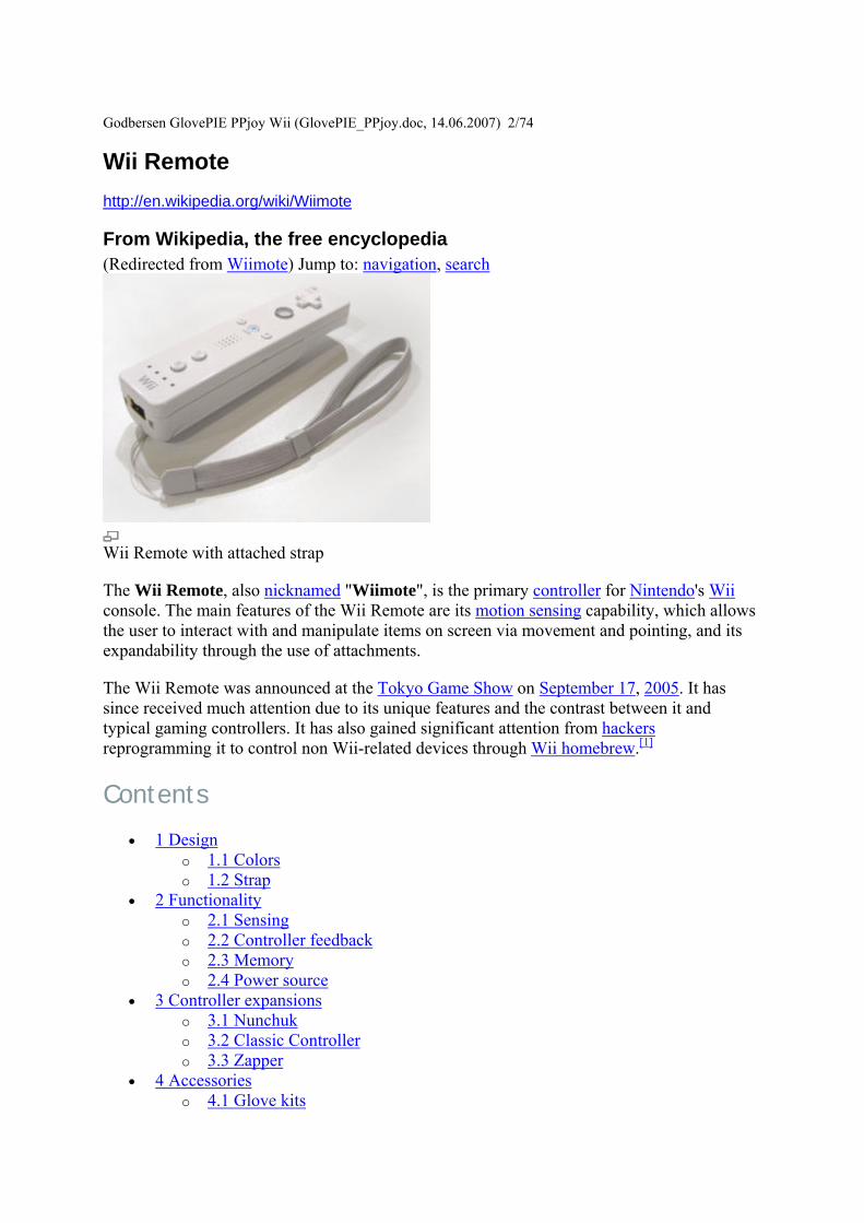
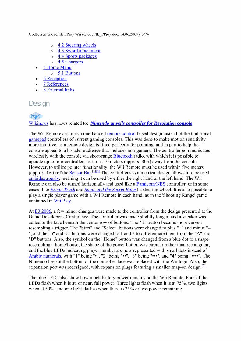
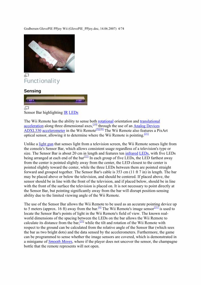
Godbersen GlovePIE PPjoy Wii (Glov
ePIE_PPjoydoc 14062007) 474
Functionality
Sensing
Sensor Bar highlighting IR LEDs
The Wii Remote has the ability to sense both rotational orientation and translational acceleration along three dimensional axes[19] through the use of an Analog Devices ADXL330 accelerometer in the Wii Remote[5][20] The Wii Remote also features a PixArt optical sensor allowing it to determine where the Wii Remote is pointing[21]
Unlike a light gun that senses light from a television screen the Wii Remote senses light from the consoles Sensor Bar which allows consistent usage regardless of a televisions type or size The Sensor Bar is about 20 cm in length and features ten infrared LEDs with five LEDs being arranged at each end of the bar[22] In each group of five LEDs the LED farthest away from the center is pointed slightly away from the center the LED closest to the center is pointed slightly toward the center while the three LEDs between them are pointed straight forward and grouped together The Sensor Bars cable is 353 cm (11 ft 7 in) in length The bar may be placed above or below the television and should be centered If placed above the sensor should be in line with the front of the television and if placed below should be in line with the front of the surface the television is placed on It is not necessary to point directly at the Sensor Bar but pointing significantly away from the bar will disrupt position-sensing ability due to the limited viewing angle of the Wii Remote
The use of the Sensor Bar allows the Wii Remote to be used as an accurate pointing device up to 5 meters (approx 16 ft) away from the bar[6] The Wii Remotes image sensor[21] is used to locate the Sensor Bars points of light in the Wii Remotes field of view The known real-world dimensions of the spacing between the LEDs on the bar allows the Wii Remote to calculate its distance from the bar[23] while the tilt and rotation of the Wii Remote with respect to the ground can be calculated from the relative angle of the Sensor Bar (which sees the bar as two bright dots) and the data sensed by the accelerometers Furthermore the game can be programmed to sense whether the image sensors are covered which is demonstrated in a minigame of Smooth Moves where if the player does not uncover the sensor the champagne bottle that the remote represents will not open
Godbersen GlovePIE PPjoy Wii (GlovePIE_PPjoydoc 14062007) 574 The Sensor Bar is required when the Wii Remote is controlling up-down left-right motion of a cursor or reticle on the TV screen to point to menu options or objects such as enemies in first person shooters Because the Sensor Bar also allows the Wii Remote to calculate the distance between the Wii Remote and the Sensor Bar[24] the Wii Remote can also control slow forward-backward motion of an object in a 3-dimensional game[25] Rapid forward-backward motion such as punching in a boxing game is controlled by the acceleration sensors Using these acceleration sensors (acting as tilt sensors) the Wii Remote can also control rotation of a cursor or other objects[26]
The use of an infrared sensor to detect position can cause some detection problems when other infrared sources are around such as incandescent light bulbs or candles This can be easily alleviated by using fluorescent lights around the Wii which emit little to no infrared light[27] Innovative users have used other sources of IR light as Sensor Bar substitutes such as a pair of flashlights and a pair of candles[28] Such substitutes for the Sensor Bar illustrate the fact that a pair of non-moving lights provide continuous calibration of the direction that the Wii Remote is pointing and its physical location relative to the light sources There is no way to calibrate the position of the cursor relative to where the user is pointing the controller without the two stable reference sources of light provided by the Sensor Bar or substitutes
The position and motion tracking of the Wii Remote allows the player to mimic actual game actions such as swinging a sword or aiming a gun instead of simply pushing buttons An early marketing video showed actors miming actions such as fishing cooking drumming conducting a string quartet shooting a gun sword fighting and performing dental surgery[29]
Controller feedback
The Wii Remote also provides basic audio and rumble functionality At the 2006 E3 press conference it was revealed that the Wii Remote has its own independent speaker on the face of the unit This was demonstrated by a developer as he strung and shot a bow in The Legend of Zelda Twilight Princess The sound from both the Wii Remote and television was altered as the bow shot to give the impression of the arrow traveling away from the player Another example of its use is in Red Steels Killer match where the players will receive their objective through the Wii Remote The speaker has been noted for being low quality and small emitting poor quality sound especially at high volumes[30] although the volume can be changed with the Home button and selecting the corresponding controller icon at the bottom of the screen[31]
Memory
The Wii Remote contains a 16 KiB EEPROM chip from which a section of 6 kilobytes can be freely read and written by the host[27][32] Part of this memory is available to store up to 10 Mii avatars which can be transported for use with another Wii console At least 4000 bytes are available and unused before the Mii data which may be used in future games
Power source
The Wii Remote uses two AA batteries as a power source which can power a Wii Remote for 60 hours using only the accelerometer functionality and 30 hours using both accelerometer and pointer functionality[27] An official direct recharging option for the Wii Remote has not
Godbersen GlovePIE PPjoy Wii (GlovePIE_PPjoydoc 14062007) 674 yet been revealed but various third-party manufacturers market charging solutions for the controller (see section on chargers) According to an interview with Nintendo industrial designer Lance Barr limitations of the Wii Remotes expansion port make it unlikely that it will be used for internal battery charging[33] Although the Wii manual discourages the use of rechargeable batteries Nintendos support website has indicated that NiMH rechargeable batteries may be used[34] A 3300uF capacitor provides a temporary source of power during quick movements of the Wii Remote when connection to the batteries may be temporarily interupted[35]
Controller expansions
The Wii Remote also features an expansion port at the bottom which allows various functional attachments to be added to the controller The following attachments are currently known
Nunchuk
The Nunchuk (left) plugged into a pre-release model of the Wii Remote as shown at E3 2006
The Nunchuk is the first controller attachment Nintendo revealed for the Wii Remote at the 2005 Tokyo Game Show It connects to the Wii Remote via a long cord and its appearance while attached resembles the nunchaku It features an analog stick similar to the one found on the Nintendo GameCube controller and two trigger buttons (a last minute modification changed the two triggers to one trigger and a C button as described below) It works in tandem with the main controller in many games Like the Wii Remote the Nunchuk also provides accelerometer for three axis motion-sensing and tilting but without a speaker a rumble function or a pointer function[6][36][37]
A Nunchuk comes bundled with the Wii console[38][39] Separate Nunchuks retail in Japan for JPyen1800[2] in the United States for US$1999[3] in Canada for CA$2499 in Europe for euro19[4] and in the United Kingdom for pound14[4]
Godbersen GlovePIE PPjoy Wii (GlovePIE_PPjoydoc 14062007) 774 The two shoulder buttons formerly named Z1 and Z2 respectively had been reshaped and renamed since the Game Developers Conference The circular top shoulder button now called C is much smaller than the lower rectangular shoulder button now called Z The C button is oval shaped while the Z button is square[40]
The body of the Nunchuk measures 113 mm long 382 mm wide and 375 mm thick[5] The cord for the Nunchuk is approximately three and a half to four feet long In the original design of the Nunchuk it was much longer The connection port was also larger[1]
Product images and an Overstockcom listing indicate that game accessory manufacturer Intec is releasing a third-party Nunchuk for the Wii Remote This is the first third-party expansion to be discovered for the Wii Remote[41]
Classic Controller
The Classic Controller connected to the Wii Remote
During E3 2006 Nintendo introduced a Classic Controller which plugs into the Wii Remote via a cord similar to the Nunchuk[5] The Classic Controllers look is roughly modelled on the controller scheme used for the SNES but with two additional analog sticks and two extra shoulder buttons (the ZL and ZR buttons used to replicate the Z button found on the Nintendo 64s controller) The overall configuration is similar to that of other major seventh generation console controllers
The Classic Controllers cord comes out the bottom instead of the top of the controller (a configuration shared by the Dreamcast controller) The Classic Controller contains slots on its backside opened via a rectangular button at the top of the controller presumably for clipping the controller to something else[42] The purpose for these slots remains undisclosed[43] but it is commonly believed to be used with a special clip that attaches the Wii Remote to the Classic Controller enabling it to have abilities similar to the PlayStation 3 controller as well as provide similar controls to the Nintendo 64 controller Nyko had announced they are releasing such a clip in addition to a grip shell and a place to store the cable[44] The body of the Classic Controller measures 657 mm tall 1357 mm wide and 26 mm thick[5] The Classic Controller does not feature an accelerometer or a rumble function
The Classic Controller cannot be used to play Nintendo GameCube games According to the Nintendo Online Shop the Classic Controller can only be used with Virtual Console games (although some Wii games such as Dragon Ball Z Budokai Tenkaichi 2 and Super Smash Bros Brawl can be played with it) The Nintendo GameCube controller can be used instead of the Classic Controller for playing most Virtual Console games When in the Wii Menu the left analog stick takes control of the cursor when the Wii Remote is not pointed at the screen The Classic Controller can navigate through the Message Board Settings menus and Shop
Godbersen GlovePIE PPjoy Wii (GlovePIE_PPjoydoc 14062007) 874 Channel However it becomes inactive on the Mii Photo Forecast News Internet and Everybody Votes channels
Nintendo had previously announced a controller shell which resembled a traditional game controller often referred to as a classic-style expansion controller[45] As described at the time the Wii Remote would fit inside the shell allowing gamers to play games using a traditional-style gamepad while allowing use of the remotersquos motion sensing capability It would allow controls similar to a PlayStation 3 controller According to Satoru Iwata it would be meant for playing the existing games Virtual Console games and multi-platform games[46]
The Classic Controller features two analog sticks a D-pad face buttons labeled a b x and y analog shoulder buttons labeled L and R and two Z buttons (labeled ZL and ZR) next to the L and R buttons respectively It also has a set of - Home and + buttons like those on the Wii Remote with the - and + buttons labeled Select and Start respectively
Classic Controllers retail in Japan for JPyen1800[2] in the United States for US$1999[47] in Canada for CA$2499 in Europe for euro19[4] in Australia for AU$2999 and in the United Kingdom for pound15[4]
Zapper
Zapper shell with the Wii Remote
Nintendo has showcased a gun shell peripheral concept design for the Wii Remote known as Zapper The name is a throwback to the NES Zapper light gun for the Nintendo Entertainment System The Wii Remote slots into the gun barrel of the shell[48] The shell features a trigger hole as well as an analog stick on the top of the handle[49] making it similar to the Nunchuk attachment but without the accelerometer and the second button Nintendo has not announced whether the Zapper will be produced for sale
In early April video game retailer GameStop listed a Wii Blaster peripheral on its website with a release date of May 1 2007 Originally listed without a specified manufacturer the Wii Blaster had been speculated to be the Zapper[2] but has since been indicated to be produced by third party accessories manufacturer Core Gamer According to GameStop on May 5 2007 the Wii Blaster release date has changed to June 26 2007 and is available for pre-ordering[50]
While not technically an expansion details on an aesthetic gun accessory for the Wii Remote and Nunchuk named the Sharp Shooter have been released by third-party manufacturer Joytech[51] In this accessory the Wii Remote is housed in the gun barrel The Nunchuk is fitted into the handle so that the Nunchuk triggers serve as gun triggers
Godbersen GlovePIE PPjoy Wii (GlovePIE_PPjoydoc 14062007) 974
Accessories While few third-party controller expansions have been revealed many aesthetic and ergonomic accessories have been developed for the Wii Remote including texturized covers and extensions shaped like tennis rackets baseball bats and golf clubs[52]
Glove kits
Glove kits have been produced that allow a better grip on the Wii Remote These are available in several colors some of which glow in the dark or change hue from the heat of the players hand
Steering wheels
Introduced by Ubisoft the Wii Steering Wheel is an accessory shell for the Wii Remote developed by Thrustmaster and is bundled with certain games such as Monster 4x4 World Circuit and GT Pro Series[53] The accessory which is only for aestheticergonomic enhancement is meant for driving-style gameplay in which the Wii Remote would be held lengthwise in a two-handed gamepad orientation steering the subject by tilting the controller The Wii Steering Wheel is also sold separately for US$1699 Since the Wii Steering Wheel was revealed other similarly designed steering wheel accessories have been produced including the Wii Racing Wheel by Intec[3]
Sword attachment
A sword and shield attachment has been released by ASiD These accessories are simply shells and do not provide any other functional purpose The kit comes with a sword a shield and a knife (more of a curved sword resembling a scimitar) all in the monochromatic white design of the Wii hardware The Wii Remote slides into the handle of the sword (or knife) and the Nunchuk clips into the back of the shield
Sports packages
The Wii Sports pack was released by GameStop in the United States and Logic3 in Europe It includes a baseball bat a golf club and a tennis racket It is very similar to the sword accessory and attaches to the Wii Remote to allow a more realistic experience with Wii Sports
The boxing gloves are a seperate accessory to the Wii Sports pack With those the player can put the Wii Remote and Nunchuk inside each glove underneath where one slips in hands The Nunchuk is assigned to the left glove while the Wii Remote is right In this way one can punch like an actual boxer instead of jabbing the controllers away from oneself
Chargers
While Nintendo does not currently offer a rechargeable option for the Wii Remote recharging systems have been developed by various third-party peripheral companies Nyko sells a direct-charging system for two Wii Remote units which is powered using an AC power adapter and uses a special battery pack and a cover with electrical contacts for charging and
Godbersen GlovePIE PPjoy Wii (GlovePIE_PPjoydoc 14062007) 1074 silicon texturing to add grip Nyko prices the system at US$2999[54] Another two-controller charging system sold by Joytech is powered through a USB connection which allows the unit to charge the Wii Remote through the Wii console Like the Nyko charging station the Joytech system includes two sets of special battery packs and covers with electrical contacts for charging The Joytech station features extensions on both sides for holding Nunchuks Joytech prices the system at US$39[55] Brando Workshop offers a USB-powered one-controller charging system with a combination charging standNunchuk cradle[4] While not a direct-recharging system like the others the Thrustmaster T-Charge NW combines a organizerstorage system for a Wii Remote and Nunchuk with a two-cell AA battery charger and includes a set of unobtrusive grips[56]
Home Menu
Accessed with the Wii Remotes home button the Home Menu displays information about the controller(s) currently being used and allows the user to configure certain options At the bottom of the menu screen the battery life of all connected controllers is displayed Below that is a bar labelled Wii Remote Settings Selecting it brings you to an options screen where you can control the audio output volume force feedback and recalibrate the controller
Buttons
Depending on when the Home Menu is accessed there will be a different amount of buttons displayed
Wii Menu No matter when the menu is accessed the Wii Menu button will always be present Selecting this will bring back the Wii Menu where one can choose another channel
Reset During gameplay the Reset button is also shown This allows the user to go back to the games title screen However all unsaved data is lost so it is wise to save game progress before resetting
Operations Guide On Wii Menu channels including the News Channel Forecast Channel Everybody Votes Channel Internet Channel and Virtual Console titles the Operations Guide button will appear on the Home Menu It provides brief explanations on the currently open application
Reception Overall reception to the Wii Remote has changed over time The control styles provided by the controller were met with praise at its first public exhibition at E3[57] Since then comments have been noted by the press on its functionality Matt Wales of IGN UK highlighted the aiming and precision of Red Steel and stated Taking down swathes of enemies with nothing more than a twitch of the wrist proves immensely satisfying and more importantly incredibly involving[58]
Other publications have noted specific complaints regarding control GameSpot expressed that some motions in Cooking Mama Cook Off failed to transmit or meet expectation during gameplay[59] Similar observations were made on other titles made available during the Wii
Godbersen GlovePIE PPjoy Wii (GlovePIE_PPjoydoc 14062007) 1174 launch period ComputerAndVideoGamescom reported that Most prominent is the first batch of games many of which do a better job at exposing the obstacles of full motion control rather than the benefitsRed Steel is twitchy and occasionally clumsy Need For Speedis near unplayable Far Cry got it all wrong and the motion control in Marvel Ultimate Alliance just feels tacked on[60]
The overall situtation was described by Joystiq thusly Over the months since launch the unpredictable Wii Remote has led to a maddening dichotomy Some games are too easy while others are too hard -- for all the wrong reasonsGamers who crave a deeper challenge have to settle for battling incomprehensible controls[61] Critics felt that fault was largely attributed to the developers lack of experience with the Wii Remote Jeremy Parish of EGM compared the initial phase of control implementation to that of the Nintendo DS[62] Matt Casamassina of IGN also presumed that the first generation of Wii games were of an experimental stage and that potential for refinement had yet to be exploited[63]
Later-released titles have seen mixed reactions in terms of control Of Tiger Woods PGA Tour 07 from EA Games Matthew Kato of Game Informer stated that the controller has a hard time detecting your backswing Thus itrsquos harder to control There were even times the game putted for me by accident[64] A GamePro review for Medal of Honor Vanguard offers that the title is an encouraging sign that developers are finally starting to work out the kinks and quirks of the Wii Remote[65]
References
1 ^ Jamin Brophy-Warren Magic Wand How Hackers Make Use Of Their Wii-motes Wall Street Journal April 28 2007
2 ^ a b c Japanese Conference Updates DONE N-Sider Retrieved on 2006-12-24 3 ^ a b Matt Casamassina Live from New York Were at Nintendos Wii event Live
updates begin now IGN Retrieved on 2006-12-24 4 ^ a b c d e f Wii European launch details announced Nintendo Retrieved on 2006-12-
24 5 ^ a b c d e f (Japanese) - Nintendo Company Ltd Retrieved on
2006-09-14 6 ^ a b c Nintendo Wii - Hardware Information Nintendo of America Retrieved on
2006-05-09 7 ^ wwwdestructoidcomnintendo-wiimote-change-before-after-puberty Retrieved on
2007-03-19 8 ^ httpmediawiiigncommedia821821973vid_1492011html 9 ^ httpmediacubeigncomarticles651651334vids_1html 10 ^ IGN Snaps Photos of Black Wii at THQ Event Then Takes Them Down Play
Feed Retrieved on 2006-12-24 11 ^ Wishnov Jason (2006-11-27) Fancy Wii skins Nintendo Fan Boy Retrieved on
2006-12-24 12 ^ Summa Robert New photos from THQs Wii event - update 1 Retrieved on 2007-
02-24 13 ^ Gantayat Anoop (2006-09-14) Wii Quotables IGN Retrieved on 2007-02-24 14 ^ Broken Wii Controller (video) IGN Retrieved on 2007-02-24 15 ^ Customer Service gt Wii gt Safety Information Nintendo Retrieved on 2007-02-24
Godbersen GlovePIE PPjoy Wii (GlovePIE_PPjoydoc 14062007) 1274
16 ^ Sliwinski Alexander (2006-12-08) Jumpin jinkies new Wii straps joystiqcom Retrieved on 2007-02-24
17 ^ Nintendo Issue Replacement Wii Wrist Straps Official Nintendo Magazine (2006-12-15) Retrieved on 2007-02-24
18 ^ Nintendo of America Initiates Replacement Program for Wrist Straps Used with Controllers for the Wii Video Game System US Consumer Product Safety Commission (2006-12-15) Retrieved on 2007-02-24
19 ^ Will Wii Rock You p 3 thinkdigitcom (2007) Retrieved on 2007-03-23 20 ^ Wisniowski Howard (2006-05-09) Analog Devices And Nintendo Collaboration
Drives Video Game Innovation With iMEMS Motion Signal Processing Technology Analog Devices Inc Retrieved on 2006-05-10
21 ^ a b Castaneda Karl (2006-05-13) Nintendo and PixArt Team Up Retrieved on 2007-02-24
22 ^ Troubleshooting the Wii Remote amp Sensor Bar Nintendo Retrieved on 2007-02-24 23 ^ Nintendo patent application 20070060384 Figure 16 and paragraph 0115 24 ^ Nintendo patent application 20070060384 Figure 16 and paragraph 0115 25 ^ Termed Pushing or Pulling in the Wii Operations Manual System Setup page 25 26 ^ Termed Twisting in the Wii Operations Manual System Setup page 25 27 ^ a b c Casamassina Matt (2006-07-14) Wii Controllers Unlocking the Secrets IGN
Retrieved on 2006-07-14 28 ^ Using two candles as a Wii Sensor Bar replacement YouTube Retrieved on 2006-
09-24 29 ^ TGS 2005 Revolution Teaser Video (video) IGN Retrieved on 2006-03-16 30 ^ Gerstmann Jeff (2006-12-12) The Legend of Zelda Twilight Princess CNET 31 ^ James Sander-Cederlof (2007-02-17) Wii Hardware FAQ GameFAQs Retrieved
on 2007-02-24 32 ^ Wii-mote Guts Spark Fun Electronics (2006-12-19) Retrieved on 2007-03-28 33 ^ Wii Controllers No Recharging Yet The Wiire Retrieved on 2006-05-11 34 ^ Set Up of the Wii Remote Nintendo Retrieved on 2006-11-26 35 ^ Wii-mote Guts Spark Fun Electronics Retrieved on 2006-12-19 36 ^ STMicroelectronics Drives Gaming Revolution with Nintendos Wii (2006-05-09)
Retrieved on 2006-05-12 37 ^ RUMOR The Wii Nunchuck rumble rumor surfaces again (2006-10-28)
Retrieved on 2006-11-16 38 ^ Wales Matt (2006-05-22) Reports claim Wii to slap down 16 at launch (English)
Computer and Video Games Retrieved on 2006-05-25 39 ^ Berghammer Billy (2006-06-02) The Ultimate in PR Spin The Perrin Kaplan
Interview Part Four (English) (WMV) Game Informer Retrieved on 2006-06-08 40 ^ Hands-On with the Wii Controller (2006-05-12) Retrieved on 2006-05-12 41 ^ Luke Plunkett (November 13 2006) Third-party Nunchuks inbound
KotakucomWii Nunchuk (Intec) Overstockcom (November 29 2006) 42 ^ Greenwald Will (2006-12-07) ZDNet Nintendo Wii Classic Controller Review amp
Comparison CNET Retrieved on 2007-01-01 43 ^ Sklens Mike (2006-05-10) News Article Wii Classic Controller Revealed
NintendoWorldReport Retrieved on 2006-05-11 44 ^ IGN preview Nyko Wii classic Controller shell IGN (2007-02-23) Retrieved on
2007-02-24
Godbersen GlovePIE PPjoy Wii (GlovePIE_PPjoydoc 14062007) 1374
45 ^ Gibson Ellie (2005-09-16) Jim Merrick Takes Control Eurogamer Retrieved on 2006-05-09
46 ^ 47 ^ Vore Bryan (2006-09-15) Wii Classic Controller And Video Cable Questions
Answered Game Informer Retrieved on 2007-02-24 48 ^ Miller Ross (2006-05-10) E3 The Wii Zapper prototype revealed Joystiq
Retrieved on 2006-05-11 49 ^ Bozon Mark (2006-05-10) E3 2006 Light Gun Shell Revealed IGN Retrieved on
2006-05-10 50 ^ httpwwwgamestopcomproductaspproduct5Fid=802669 51 ^ httpwwwgamingbitscomcontentview19332 52 ^ Captain (2006-11-17) Futuretronics unveils Wii Remote shell range Aussie-
Nintendocom Retrieved on 2007-02-24 53 ^ Casamassina Matt (2006-09-08) Interview GT Pro Series IGN Retrieved on
2007-02-24 54 ^ Sliwinski Alexander (2007-01-09) Nykos Wii-chargeable Station Joystiq
Retrieved on 2007-01-20 55 ^ Stern Zack (2006-12-19) Rechargeable Wii Remote Batteries and Dock in 2007
Joystiq Retrieved on 2007-01-20 56 ^ httpgearigncomarticles775775991p1html 57 ^ 2006 Winners Game Critics Awards Retrieved on 2006-08-13 58 ^ Red Steel UK Review IGN Retrieved on May 11 2007 59 ^ Cooking Mama Cook Off Review GameSpot Retrieved on May 7 2007 60 ^ Is the novelty of Wii wearing off ComputerAndVideoGamescom Retrieved on
May 8 2007 61 ^ Cooking Mama Cook Off highlights Wii Remote issues joystiqcom Retrieved on
May 8 2007 62 ^ Jeremy Parish Elebits review (January 2007) Electronic Gaming Monthly pp 64 63 ^ N-Query IGN Retrieved on May 8 2007 64 ^ TIGER ASKS FOR A MULLIGAN gameinformercom Retrieved on May 11 2007 65 ^ Review Medal of Honor Vanguard gameprocom Retrieved on May 11 2007
External links
bull Official Nintendo Site bull Official Wii Site bull Wii Controllers page bull Accessories page bull US Patent Application 20070049374
Godbersen GlovePIE PPjoy Wii (GlovePIE_PPjoydoc 14062007) 1474
Wiimote
httpwwwwiiliorgindexphpWiimote
This page is intended to be a technical guide to the Wii Remote For an excellent high-level overview of the Wii Remote (aka Wiimote) see the Wikipedia article New information and status updates should be posted to the talk page and will eventually be digested and summarized here For more info about the physical hardware be sure to check out the hardware page
Contents
bull 1 Communication o 11 HID Interface
bull 2 Inputs o 21 Buttons o 22 Motion Sensor o 23 Calibration
231 Calibration Data o 24 IR Sensor
bull 3 Outputs o 31 Player LEDs o 32 Rumble
bull 4 Speaker o 41 Initialization Sequence o 42 Speaker Configuration o 43 Sound Data Format
bull 5 Onboard Memory o 51 Flash Memory o 52 Control Registers o 53 Reading and Writing
531 Communication with the Nunchukbull 6 Expansion Port bull 7 Batteries bull 8 See Also
Communication
The Wiimote communicates with the Wii via a Bluetooth wireless link The Bluetooth controller is a Broadcom 2042 chip which is designed to be used with devices which follow the Bluetooth Human Interface Device (HID) standard such as keyboards and mice The Bluetooth HID is directly based upon the USB HID standard and much of the same documentation applies
Godbersen GlovePIE PPjoy Wii (GlovePIE_PPjoydoc 14062007) 1574 When queried with the Bluetooth Service Discovery Protocol (SDP) the Wiimote reports back a great deal of information listed at Wii_bluetooth_specsspd info In particular it reports
Name Nintendo RVL-CNT-01 Vendor ID 0x057e Product ID 0x0306
The Wiimote sends reports to the host with a maximum frequency of 100 reports per second
The Wiimote does not require any of the authentication or encryption features of the Bluetooth standard In order to interface with it one must first put the controller into discoverable mode by either pressing the 1 and 2 buttons at the same time or by pressing the red sync button under the battery cover Once in this mode the Wiimote can be queried by the Bluetooth HID driver on the host If the HID driver on the host does not connect to the Wiimote within 20 seconds the Wiimote will turn itself off Holding down the 1 and 2 buttons continuously will force the Wiimote to stay in discoverable mode without turning off This does not work with the sync button however When in discoverable mode the Player LEDs will blink The number that blink will correspond to the remaining battery life similar to the meter on the Wii home menu where of bars = of lights
HID Interface
The HID standard allows devices to be self-describing using a HID descriptor block This block includes an enumeration of reports that the device understands A report can be thought of similar to a network port assigned to a particular service Reports are unidirectional however and the HID descriptor lists for each port the direction (Input or Output) and the payload size for each port Like all Bluetooth HID devices the Wiimote reports its HID descriptor block when queried using the SDP protocol A human-readable version of the block is shown at Wii_bluetooth_specsHID_Descriptor and is summarized in the following table
Output Report
ID Payload
Size Known Functions
0x11 1 Player LEDs Force Feedback
0x12 2 Report type ID 0x13 1 IR Sensor Enable 0x14 1 Enable speaker 0x15 1 Controller status 0x16 21 Write data 0x17 6 Read data 0x18 21 Speaker data
Input Report
ID Payload
Size Known Functions
0x20 6 Expansion Port 0x21 21 Read data 0x22 4 Write data 0x30 2 Buttons only
0x31 5 Buttons | Motion Sensing Report
0x32 16 Buttons | Expansion Port | IR
0x33 17 Buttons | Motion Sensing
Godbersen GlovePIE PPjoy Wii (GlovePIE_PPjoydoc 14062007) 1674
0x19 1 Mute speaker
0x1a 1 IR Sensor Enable 2
Report
0x34 21 Buttons | Expansion Port | IR
0x35 21 Buttons | Motion Sensing Report | Expansion Port
0x36 21 Buttons | Expansion Port | IR
0x37 21 Buttons | Motion Sensing Report | Expansion Port
0x38 21 Buttons | Motion Sensing Report | IR
0x3d 21 Buttons | Expansion Port | IR
0x3e 21 Buttons | Motion Sensing Report | IR
0x3f 21 Buttons | Motion Sensing Report | IR
Note that Output refers to packets are sent from the host to the Wiimote and Input refers to packets that are sent from the Wiimote to the host For clarity the convention in this document is to show packets including the Bluetooth header (in parentheses) report ID (also called channel ID in some places) and payload as described in sections 73 and 74 of the Bluetooth HID specification Each byte is written out in hexadecimal without the 0x prefix separated by spaces For example
(a1) 30 00 00
is a DATA input packet (0xa1) on channel 0x30 with the two byte payload 0x00 0x00
It actually seems that Force Feedback is accessible through ALL output channels the same way
Note On some wii-motes IR wont start transmitting until a read-report 0x38 has been sent
Inputs
Buttons
There are 12 buttons on the Wiimote Four of them are arranged into a directional pad and the rest are spread over the controller
By default whenever a button is pressed or released a packet is sent to the host via HID input report 30H with a payload containing a 2-byte bitmask with the current state of all the buttons
Godbersen GlovePIE PPjoy Wii (GlovePIE_PPjoydoc 14062007) 1774 The button state also seems to be included in the first two bytes of all other input reports
Some of the bits in the first two bytes dont seem to be directly related to button presses and are somewhat unknown
For example when the A button is pressed this HID DATA input packet is received
(a1) 30 00 08
and when it is released this is packet received
(a1) 30 00 00
The bit assignments (in big endian order) for the buttons are
Button Number (dec) Value (hex) Two 1 0x0001 One 2 0x0002 B 3 0x0004 A 4 0x0008 Minus 5 0x0010 Unknown (motion reports) or Z Acceleration bit 6 (report 3E) or bit 2 (report 3F) 6 0x0020
X Acceleration LSB (motion reports) or Z Acceleration bit 7 (report 3E) or bit 3 (report 3F) 7 0x0040
Home 8 0x0080 Left 9 0x0100 Right 10 0x0200 Down 11 0x0400 Up 12 0x0800 Plus 13 0x1000 Y Acceleration LSB (motion reports) or Z Acceleration bit 4 (report 3E) or bit 0 (report 3F) 14 0x2000
Z Acceleration LSB (motion reports) or Z Acceleration bit 5 (report 3E) or bit 1 (report 3F) 15 0x4000
Unknown 16 0x8000
The power button is unusual in that it sends a disconnect request when held down instead of emitting a normal button code
Godbersen GlovePIE PPjoy Wii (GlovePIE_
PPjoydoc 14062007) 1874
Motion Sensor
Coordinate system used by Wiimote
The motion of the remote is sensed by a 3-axis linear accelerometer located slightly left of the large A button The integrated circuit is the ADXL330 (data sheet) manufactured by Analog Devices This device is physically rated to measure accelerations over a range of at least +- 3g with 10 sensitivity
Inside the chip is a small micro mechanical structure which is supported by springs built out of silicon Differential capacitance measurements allow the net displacement of the tiny mass to be converted to a voltage which is then digitized It is important to note that the sensor does not measure the acceleration of the Wiimote but rather the force exerted by the test mass on its supporting springs Due to the sign convention used this quantity is proportional to the net force exerted by the players hand on the Wiimote when holding it Thus at rest on a flat table the accelerometer reports vertical force of +g (the mass can be normalized away into the aribitrary units) and when dropped reports a force of nearly zero
The sensor uses a right-handed coordinate system with the positive X-axis to the left and the positive Z-axis pointing upward when the remote is held horizontally as shown in the diagram at the right Forces on each axis are digitized to 8 bit unsigned integers with the zero scale set to 0x80 Manufacturing and calibration defects of course cause some intrinsic zero offsets However the Earths gravitational field and a flat level surface upon which to rest the remote in principle allow any offsets or chip skew to be measured and calibrated away in software The calibration values are stored near the start of the Wiimotes flash RAM Decomposing the force measured by the sensor into rotation and linear components is tricky and discussed further on the Motion analysis page
Godbersen GlovePIE PPjoy Wii (GlovePIE_PPjoydoc 14062007) 1974 The Wiimote does not normally report motion sensor readings to the host but can be requested by sending SET_REPORT request to channel 0x12
(52) 12 00 31
The 3rd byte is a bitmask 0x01 turns on the rumble and 0x04 turns on continuous output If 0x04 is not set packets are only output when the values change (almost always when the motion sensor is enabled) If 0x04 is set values are output continuously In continuous mode the device will send data at 100 packages per second Its obvious when channelmode 0x30 is chosen which disables motion readback With byte3=0x04 the button values are output multiple times a second With byte3=0x00 they are output only when you press or release a button
The 4th byte specifies which HID channel to which log sensor output should be sent After receiving this command once the Wiimote will send back stream of DATA INPUT packets on the requested channelmode (0x31 in the above example) where in reports 0x31 0x33 0x35 and 0x37 the 5th 6th and 7th bytes contain the X Y and Z readings of the accelerometer A sample packet when the Wiimote is at rest face up on a table is
(a1) 31 40 20 86 8a a5
where 0x86 is the X-axis measurement 0x8a is the Y-axis measurement and 0xa5 is the Z-axis measurement The first two bytes of the payload 0x40 and 0x20 are the button values and some other bits These bits are important in reports 0x3E and 0x3F The button values are still in the same place and have the same meanings as in the Buttons section
Other channels can be selected for motion sensor reports including 0x31 0x33 0x35 0x37 0x3e and 0x3f If either 0x3e or 0x3f are selected then sensor readings will alternate between the two channels 0x3E contains the X Acceleration in the third byte of the payload wheras 0x3F contains the Y Acceleration in the third byte of the payload The Z Acceleration is stored in the button flags as shown in the button table above 0x3E and 0x3F use the remaining 18 bytes for what we think is IR data
The length of the report payload will depend upon the channel as show in the table in HID Interface section Channels which have payloads longer than needed for the motion sensor will apparently pad the end of the packet with 0xff bytes
(a1) 33 40 00 86 8a a5 ff ff ff ff ff ff ff ff ff ff ff ff ff
Motion sensor reports can be stopped by setting the output channel to 0x30
(52) 12 00 30
It seems that the channel mode is actually a mode selection bitmask Button output is always enabled Mode 0x30 is just buttons 0x31 is motion sensor 0x32 is IR camera () and 0x33 is both IR camera and motion sensor The two sets of data are tacked onto each other first the button values then the three motion sensor bytes then the camera bytes Other modes seem to include motion data and or IR data in different ways
Godbersen GlovePIE PPjoy Wii (GlovePIE_PPjoydoc 14062007) 2074 Calibration
The zero points and gravity values for the three accelerometer axes are stored near the start of the Wiimotes flash memory
Calibration Data
Calibration data for the onboard accelerometer is stored in the Wiimotes memory starting at address 0x16 This information is repeated at 0x20
0x16 zero point for X axis 0x17 zero point for Y axis 0x18 zero point for Z axis 0x19 unknown 0x1A +1G point for X axis 0x1B +1G point for Y axis 0x1C +1G point for Z axis 0x1D unknown 0x1E-0x1F checksum
IR Sensor
During RampD Nintendo discovered the motion sensors were not accurate enough to use the remote to control an on-screen cursor To correct this they augmented the remote with an infrared image sensor on the front designed to locate two IR beacons within the controllers field of view The beacons are housed within a device misleadingly called the Sensor Bar
These two sources of IR light are tracked by a PixArt sensor in the front of the Wiimote housing By tracking the locations of these two points in the sensors 2D field of view the system can derive more accurate pointing information Not much is known about this feature yet but circumstantial evidence from the NintendoPixArt press release suggests that Nintendo is using a PixArt System-on-a-Chip to process the images on-board the Wiimote and sends the minimum information needed for tracking back to the base unit Transmitting full 2D images constantly would require a prohibitive amount of bandwidth especially when multiple remotes are in use
Wiimote detects and transfers up to four IR hotspots back to the host Various amounts of data can be requested from position values only position and size to position size and pixel value The amount of different configurations are quite numerous and also ties in with the connected peripheral device
Communications with the camera module is performed via an I2C bus (or other 2-wire wired-or bidirectional serial bus) Pins 5 and 6 of the camera (see silkscreen for pin s) are the clock and data respectively The bit rate is slightly less than 400kbaud These signals are also available at TP101 (data) down between the inductors and TP26 (clock) right next to the B button pad (under the B button housing) The broadcom chip and camera are the only two devices on this bus When the camera is active it sends data at 100Hz to the broadcom chip
Godbersen GlovePIE PPjoy Wii (GlovePIE_PPjoydoc 14062007) 2174 Output format EXP is three bytes per dot recognized Bytes 0 and 1 are X and Y byte 2 is the MSBs of X and Y and a size value In binary
xxxxxxxx yyyyyyyy yyxxssss
No dot is indicated by 0xff data This means you will not see any change in the output data even if you did do all the initialization correctly unless you actually point the Wiimote at a (powered) sensor bar
Output format for FULL is unknown but we know the data is interleaved Data sent to report 0x3e contains the data for the first two dots recognized data sent to 0x3f contains the data for the next two dots recognized if any
Note that the original hidd patch has trouble with 0x00 bytes in commands Make sure youre sending the right data
It is beneficial to add a slight pause (1100 sec) between sends when setting IR mode to let the remote keep up Without these pauses the remote appears to get into an inconsistent state sometimes and will not reliably detect IR spots
Outputs
Player LEDs
The bottom edge of the remote body contains 4 blue LEDs These LEDs are used during normal play to indicate that the remote is in Bluetooth discoverable mode (all blinking) or to indicate the player number of the controller (one light illuminated) The LEDs are independently controllable however using SET_REPORT output packet to channel 11 which has a payload size of 1 The most-significant 4 bits control each LED with bit 4 corresponding to the player 1 LED Channel 11 also can control the rumble feature so it is best to keep the 4 least-significant bits zero in order to avoid vibrating the controller For example this packet turns on the player 1 LED only
(52) 11 10
Since each LED has its own bit any combination of LEDs can be illuminated Updating the LED mask rapidly (multiple times a second) will cause all four LEDs to blink as if the remote is in pairing mode Once there has been a short delay since the last LED mask update the most recently set mask will appear again though and the blinking will stop
Rumble
Rumble is provided via motor with an unbalanced weight attached inside the Wiimote which can be activated to cause the controller to vibrate The motor can be activated by sending a SET_REPORT output packet to channels 0x11 0x13 0x14 0x15 0x19 or 0x1a with the least significant bit set
(52) 13 01
And the vibration can be turned off by clearing the bit
Godbersen GlovePIE PPjoy Wii (GlovePIE_PPjoydoc 14062007) 2274 (52) 13 00
So far it appears all channels are equivalent though using channel 0x11 is not advised because it also controls the player LEDs
Speaker
The Wiimote has a small low-quality speaker used for short sound effects during gameplay The sound is streamed directly from the host and the speaker has some adjustable parameters The speaker is not fully reverse engineered yet
The speaker is controlled by using three output reports together with a section of the register address space of the Wiimote
Report 0x14 is used to enable or disable the speaker Setting bit 2 will enable the speaker and clearing it will disable it For example to enable the speaker send
(52) 14 04
Report 0x19 is used to mute or unmute the speaker and works identically to report 0x14 0x04 will mute the speaker and 0x00 will unmute it
Report 0x18 is used to send speaker data 1-20 bytes may be sent at once
(52) 18 LL DD DD DD DD DD DD DD DD DD DD DD DD DD DD DD DD DD DD DD DD
LL specifies the data length shifted left by three bits The DD bytes are the speaker data To fulfill the report length requirements the data must be padded if it is less than 20 bytes long Sound data must be sent at roughly the proper rate You can choose the rate by setting the sample rate during initialization
Initialization Sequence
The following sequence will initialize the speaker
1 Enable speaker (Send 0x04 to Output Report 0x14) 2 Mute speaker (Send 0x04 to Output Report 0x19) 3 Write 0x01 to register 0x04a20009 4 Write 0x08 to register 0x04a20001 5 Write 7-byte configuration to registers 0x04a20001-0x04a20008 6 Write 0x01 to register 0x04a20008 7 Unmute speaker (Send 0x00 to Output Report 0x19)
Speaker Configuration
7 bytes control the speaker settings known to include sample rate and volume at this time The gray bytes in the following example sequence are unknown bytes at this time 0x00 0x00 0x00 0x0C 0x40 0x00 0x00
Godbersen GlovePIE PPjoy Wii (GlovePIE_PPjoydoc 14062007) 2374 The red 0x0C value in byte 3 specifies the sample rate divisor based on approximately a 48000Hz starting rate This means that higher values are lower sample rates with the 0x00 value acting in a (currently) unknownundefined state meaning the divisor is taken directly and literally
Value Sample Rate 11 (0x0B) 40004364Hz (~4200Hz)12 (0x0C) 36924000Hz (~3920Hz)13 (0x0D) 34293692Hz (~3640Hz)14 (0x0E) 32003429Hz (~3360Hz)15 (0x0F) 30003200Hz (~3080Hz)
Assuming 40 samples per report you would need to send 100 reports per second to use the value 12 (0x0C) That is about the limit of what has been gotten to work
The blue 0x40 in byte 4 appears to be the volume-control byte at this time Any value from 0(0x00) to 255(0xFF) seems to work with 64(0x40) being generally accepted as a good default volume for most purposes
Sound Data Format
The sound data format is still partially unknown It seems to be 4-bit ADPCM sound
Onboard Memory
Flash Memory
On a blank Wiimote which was bought separately and has never been connected to a Wii and has never received a report other than 0x17 (read memory) with the first byte as 00 the memory is structured like this
Addresses 0x0000 to 0x003F
A1 AA 8B 99 AE 9E 78 30 A7 74 D3 A1 AA 8B 99 AE 9E 78 30 A7 74 D3 82 82 82 15 9C 9C 9E 38 40 3E 82 82 82 15 9C 9C 9E 38 40 3E 00 00 00 00 00 00 00 00 00 00 00 00 00 00 00 00 00 00 00 00 00 00
This is basically two sequences each repeated twice
A1 AA 8B 99 AE 9E 78 30 A7 74 D3 A1 AA 8B 99 AE 9E 78 30 A7 74 D3 82 82 82 15 9C 9C 9E 38 40 3E 82 82 82 15 9C 9C 9E 38 40 3E
Godbersen GlovePIE PPjoy Wii (GlovePIE_PPjoydoc 14062007) 2474 The three bytes starting at 0x16 and 0x20 (the first 3 bytes of the 3rd and 4th line above) store the calibrated zero offsets for the accelerometer Presumably the 9C 9C 9E stores the force of gravity on those axes
Addresses 0x0040 to 0x0FC9 all zeros on a newly bought Wiimote
Address 0x0FCA to 0x12B9 Mii Data block 1 all zeros on a newly bought Wiimote
Address 0x12BA to 0x15A9 Mii Data block 2 all zeros on a newly bought Wiimote
Address 0x15AA to 0x15FF all zeros on a newly bought Wiimote
Addresses 0x1600 to 0xFFFF Dont exist They return an error if you try to read from them You wont get the error if you start reading from at or before the 0x15FF boundary but you will just get zeroes for the invalid bytes in that case
For the Flash memory the address is only 2 bytes So address 0x010000 is the treated the same as address 0x0000 This is true all the way up to 0xFF0000 That byte (0x00FF0000) is always ignored unless the most significant byte (0xFF000000) has bit 2 (0x04) set
Spark Funs EEPROM dump of their Wiimote seems to suggest that the Bluetooth-readable portion of the EEPROM starts at 0x0070 on the physical device More interesting is the fact that Spark Fun claims that unencrypted 8051 code is on the same chip Device names are also present (Nintendo RVL-CNT-01) that show up when scanning for the device on a PC The first three bytes of the Wiimotes BD address do not appear in the dump suggesting that the Bluetooth chip has some storage itself for such things
Control Registers
The control registers have bit 2 (0x04) set in the first byte Bit 0 (0x01) in the first byte is the rumble flag and is not considered part of the address so 0x05A20000 is the same address as 0x04A20000 Only registers 0x04A20000 to 0x04A30000 are readable But they dont seem to provide any useful information on a fresh new Wiimote
Registers 0x04000000 - 0x49FFFFF return error 7 (instead of error 8 like normal nonexistant memory) Perhaps it is write only or perhaps it doesnt exist
Registers 0x04A00000 - 0x4A1FFFF dont exist because they return error 8 (like normal non-existant memory)
Registers 0x04A20000 - 0x4A30000 seem to control the speaker They are readable Originally they are all the byte 0xFF Except registers whose address ends in 0xFF which are the byte 0x00
Registers 0x04B00000 - 0x4BFFFFF return error 7 when you read them but some of them are known to be settable and to control the IR camera in the Wiimote The first 9 bytes are part of the IR sensitivity settings Bytes 0x04B0001A and 0x04B0001B are also part of the IR sensitivity settings Byte 0x04B00030 turns IR on and off (8 is on 1 is off in order to set
Godbersen GlovePIE PPjoy Wii (GlovePIE_PPjoydoc 14062007) 2574 sensitivity) Byte 0x04B00033 sets the IR mode (0x33 tells it to return IR data as 4 lots of 3 bytes)
Registers 0x04C00000 - 0x4FFFFFF return error 7 when you read them
Reading and Writing
We can read data with the command
(52) 17 FF FF FF FF SS SS
FF FF FF FF is the offset (big-endian format) SS SS (big-endian format) is the size in bytes
It was once thought that this was the correct format
(52) 17 0r 00 FF FF SS SS
The low bit of the first byte (of the address) is the usual rumble flag The rumble flag is not part of the address You should always set this bit to whatever the current rumble state should be It does not affect the address If you dont set this bit to the current rumble state you will accidentally change the rumble state just by reading (or writing) the memory
There is only 55K of Flash RAM on the Wiimote which is addressed between 0x0000 and 0x15FF But there are also internal control registers which can be set but only some of them can be read The control registers begin with 0x04 The returned packets store addresses as only two bytes And addresses wrap around after 0xFFFF
The responses look like this
btns SE FF FF data vvvvv vv vv vv v------gt (a1) 21 80 00 f0 11 f0 80 6c 8c c7 c2 5d 2e bd 40 00 4e 00 99 80 08 b1
E is the error flag E is 8 if you try to read from bytes that dont exist (are greater than 55K or 0x15FF) and 7 if you try to read from write-only registers or 0 if no error S (the high nibble needs to be shifted right 4 bits) is the size in bytes minus one for the current packet FF is the offset of the current packet (big-endian) Everything else is the data (16 bytes max if there is an incomplete trailer S is set to something other than 0xF and the data is padded out with zeros) If you requested more than 16 bytes then you will receive multiple packets unless you get an error where E is 8
Writing data is as follows
FF FF FF FF SS data vv vv vv vv vv v------gt (52) 16 00 00 00 00 10 57 69 69 57 69 6c 6c 52 6f 63 6b 59 6f 75 21 21
FFSS same meaning as reading (you can only write 16 bytes at a time here so SS is only one byte) 16 bytes of data follow It seems we get some kind of acknowledge on Input 0x22
Godbersen GlovePIE PPjoy Wii (GlovePIE_PPjoydoc 14062007) 2674 Note that only bit 2 (0x04) in the first byte (of payload) is considered part of the address It causes the Wiimote to write to registers instead of flash memory Bit 0 (0x01) of the first byte should be set to the current state of Rumble otherwise it will accidentally turn rumble on or off The second byte is only used for register addresses Writing to flash memory ignores this byte so 0x010000 is the same as 0x0000
Communication with the Nunchuk
See the WiimoteExtension ControllersNunchuk article for details about how the Nunchuk is to be comunicated with
Expansion Port The expansion port on the bottom of the unit is used to connect the remote to auxiliary controllers which augment the input options of the Wiimote Auxiliary controllers use the Bluetooth interface of the remote to communicate with the Wii base unit allowing them to be much simpler and cheaper to build Currently available controllers are the Nunchuk and the Classic Controller
The expansion port itself is a custom connector with 6 contacts Two of the contacts are slightly longer which allows them to make contact first when a plug is inserted The connector is not suitable for charging the remote More information is needed on the electrical specifications of this connector
The communication between the Wiimote and the [[WiimoteExtension Controllers|Extension Controllers] is 400kHz fast I2C with the slave address 0x52
The status of the expansion port is indicated with report 20H This report is sent whenever the status of the expansion port changes or when the computer sends output report 15H to request the status
After an attachment is plugged in or unplugged no other reports are sent except 20H The computer needs to send an output request (report 12H) to retrieve new input reports
The format of input report 20H consists of the report number then two bytes which are presumably the button state like in other reports then a status flags byte then two unknown 00 bytes then the battery level
Status byte flags
bit Value (hex) Flag 0 0x01 0 1 0x02 any attachment plugged in 2 0x04 Speaker enabled 3 0x08 IR sensor enabled 4 0x10 LED 1
Godbersen GlovePIE PPjoy Wii (GlovePIE_PPjoydoc 14062007) 2774 5 0x20 LED 2 6 0x40 LED 3 7 0x80 LED 4
Note that bit 2 (0x04) above is turned on by sending report 0x14 with the flag 0x04 in the payload It is turned off by sending report 0x14 without the 0x04 flag Bit 3 (0x08) above is turned on by sending EITHER report 0x13 with the flag 0x04 in the payload OR report 0x1A with the flag 0x04 in the payload You can turn it off by sending EITHER report 0x13 or 0x1A without that flag You can for example turn it on with report 0x13 and then off again with report 0x1A
For example when the classic controller or nunchuk is plugged in input report 20H is sent
(a1) 20 00 00 02 00 00 C0
The 02H indicates the classic controller or nunchuk is plugged in The C0H is the battery level and has nothing to do with the nunchuk or classic controller It will slowly decrease the more you use up the batteries but sometimes it increases
When the classic controller or nunchuk is unplugged input report 20H is sent again but with 00 instead of the 02
(a1) 20 00 00 00 00 00 C0
Batteries You can read the battery level with report 0x20 It is received when something is plugged in or unplugged from the expansion port Or you can request it by sending report 0x15 with the payload set to anything without bit 1 (rumble) set
(a1) 20 00 00 02 00 00 C0
The 0xC0 at the end is the battery level (in this case for the brand new alkaline batteries that come with it) Other batteries tested have yielded battery levels as high as 0xC6 (198 decimal) suggesting that in theory a fully charged battery might register 0xC8 (200 decimal)
Note that you may receive this message unsolicited Whether this occurs or you request this message you will need to send report 0x12 with the report number again before you will receive more data
[edit] See Also
bull Wiimote Reverse Engineering
Godbersen GlovePIE PPjoy Wii (GlovePIE_PPjoydoc 14062007) 2874
bull Motion analysis bull Wiimote driver bull WiimoteExtension ControllersNunchuk bull WiimoteExtension ControllersClassic controller bull WiimoteHardware bull Wiimote Priority bull Sensor Bar
Godbersen GlovePIE PPjoy Wii (Glov
ePIE_PPjoydoc 14062007) 2974
Motion analysis httpwwwwiiliorgindexphpMotion_analysis From Wiili Jump to navigation search
The Wiimote and Nunchuk controllers contain 3-axis accelerometers (ADXL330) which report back in arbitrary units the instantaneous force imparted on the controller by the player holding it (or whatever surface is supporting it) At rest this force is g but in the upward direction In free fall the controller reports back approximately zero force
A rigid body in 3D space however has 6 degrees of freedom 3 linear translation directions (X Y Z) and 3 rotation angles (pitch roll yaw) as shown in the figure at right
Contents
bull 1 Calibration bull 2 Tilt Position Sensing bull 3 Dynamics
o 31 Pure Rotationo 32 No Rotation o 33 Small Jerk
bull 4 Gestures bull 5 References bull 6 See Also
Calibration
If we can assume the sensor response to acceleration is roughly linear and the chip is precisely oriented on the circuit board then calibrating the Wiimote sensor is a three step procedure We only need the raw integer force sensor readings for these three positions on a flat level table
Godbersen GlovePIE PPjoy Wii (GlovePIE_PPjoydoc 14062007)
3074
bull Horizontal with the A button facing up
bull IR sensor down on the table so the expansion port is facing up
bull Laying on its side so the left side is facing up
In each of these cases we are measuring g on one axis and the zero point on the other two axes We can estimate the zero points of each axis to be
Starting with any integer reading from the sensor the calibrated force readings are
x = fracx_raw - x_0x_3 - x_0
z = fracz_raw - z_0z_1 - z_0
The calibrated force is now in units where g = 10
To give you some idea of the size of these constants for one particular Wiimote they were
7
10
95 x_3 - x_0 27
27 z_1 - z_0 27
Following a 3-step calibration procedure that requires a table might be a hassle for the user so a less rigorous procedure may be preferable Based upon the above example we might conjecture (possibly incorrectly) that the gain of the sensor (size of g basically) is more uniform between remotes than the zero offset In that case we would only need the remote to be at rest briefly in order to determine the zero offsets for all 3 axes at once Such a procedure might in fact be the only way to calibrate the Nunchuk sensor as that controller does not have the flat surfaces needed to perform the 3-step calibration
Tilt Position Sensing
bull If the remote is not accelerating the tilt of the remote can be calculated directly using the force of gravity First convert the acceleration signals from the sensors so that they vary between -1 g and +1 g (see Calibration above) Then
Godbersen GlovePIE PPjoy Wii (GlovePIE_PPjoydoc 14062007) 3174 pitch = asin(ax1 g) roll = asin(ay1 g)
bull Be careful with these equations If the remote is accelerating due to hand movement then the normalized acceleration value could be more than +1 g or less than -1 g and asin is no longer defined One way to check that the remote is not accelerating is to see if the vector sum of the three accelerometer readings is close to g
bull Note that the accelerometers become less sensitive to position when they are turned away from perpendicular to gravity (they lose resolution) For this reason the z-axis accelerometer is not very helpful for position sensing when the remote is held in the standard position However as the remote is tilted away from that position you need to use the z axis readings in addition to the other two
bull If the remote is accelerating you need to double integrate the acceleration readings to get the change in tilt relative to the last known value
bull To get an absolute value for the yaw you have to use the IR sensor If the remote is turned away from the sensor bar it should be possible to estimate the yaw using the most recent sensor bar reading the last known velocity of the sensor bar points the distance from the sensor bar (estimated from the distance between the two sensor bar points) and the integrals of the accelerometer readings However the longer you do this the more error there will be
bull For Position Sensing without the IR sensor I suggest using a button on the wiimote to set pointer to the center This way you dont even have to point the monitor (eg pointing in a slideshow or anything using a projector) This could be a solution to errors while identifying the controller position (the user sometimes points to the center of the screen and presses a button) Anyway without the IR youll difficultly achieve that sense of laser pointing
Dynamics Since all known Wiimotes are in use near the surface of the Earth there is a constant background force due to gravity even when the player is not accelerating the remote (Without the extra knowledge that we are on the Earth this force would be indistinguishable from player-induced acceleration A nice reminder of general relativity) We will assume that all axes of rotation are close enough to the motion sensor that a rotation does not linearly accelerate the sensor (ie there is no lever arm)
The acceleration a(t) measured by the sensor (not the true acceleration of the remote) is then
where is the rotation matrix which transforms from the living room frame to the local frame of the remote and is the actual acceleration of the remote in the living room
Godbersen GlovePIE PPjoy Wii (GlovePIE_PPjoydoc 14062007) 3274 frame The rotation matrix is parameterized by 3 Euler angles and the remotes linear acceleration has 3 components as well With 6 dynamical variables but only 3 observables our system is underdetermined However we can extract some information if we make simplifying assumptions
Pure Rotation
If we assume the remote experiences no acceleration (most likely at rest in normal usage conditions) then the motion sensor directly tells us which way is up From this we can derive two of the Euler angles of the controller but not the angle of rotation around the z-axis in the living room frame (corresponding to yaw in the diagram when the controller is level) This lack of knowledge is one of the reasons it is difficult to control an on-screen pointer with just 3 accelerometers The most natural motion for a user to indicate pointer movement horizontally is (roughly) to pivot the controller around the z-axis
However two angles are sufficient controls for many uses The up vector that the sensor reports can be used directly or decomposed into angles Putformulahere
No Rotation
If we assume the remote does not rotate ( ) then the only terms remaining in the motion equations are
Thus to get a good estimate of we still need to know the initial orientation of the
remote We can get this information while the remote is at rest using a method like tmentioned in the previous section
hat
Small Jerk
The amusingly named (but rarely used) term for the rate of change of acceleration is jerk The jerk term for the remote shows up in the time derivative of the force recorded by the sensor along with the rotation term that contains the angular velocity of the remote We can extract both rotation and linear acceleration if we assume a few things
bull We know the up direction before the motion starts This is bull Throughout the motion the jerk on the remote perpendicular to the current direction of
gravity is small
Then we can assume the time derivative of the force component which is perpendicular to our current estimate of the up direction is caused by the user rotating the controller only This allows us to update our estimate of the up direction for the next time step In each time step
we can also get the linear acceleration of the remote by subtracting our estimate of
Godbersen GlovePIE PPjoy Wii (GlovePIE_PPjoydoc 14062007) 3374 from the current force sensor report In effect we are integrating up a coupled set of ordinary differential equations (Note need to review the math here Beware)
The main problem with this technique is error accumulation in our estimate of up Since it is unlikely the user can keep the controller in constant linear motion without injuring themselves the TV or their opponent we can look for times when the total reported force is
close to g = 10 to recenter
Gestures
For more situations than one might first imagine it is completely unnecessary to extract precise rotations andor linear accelerations in the living room reference frame as has been described above Many games for the Wii have demonstrated the power of using the remote to issue commands though pre-defined motion patterns For example slashing with the remote to simulate a sword strike or whipping the remote around in a circle like a lasso Identifying these gesture-like commands in the motion data requires some fuzzy pattern matching which is also insensitive to small rotations of the controller AiLive is making a program called LiveMove available to Wii developers which allows them to train the system to recognize different motions by physically moving the controller in the desired pattern several times More information is in their whitepaper
(Links to other published research on this type of motion recognition are welcome here)
httpwwwcybernetcom~ccohengesturehtml contains a lot of research papers Im currently looking into the neural network approach to create a gesture system for the wiimote --Beau
References
Introduction to using accelerometers (A presentation from Analog Devices) httpwwwanalogcomAnalog_RootstaticlibrarytechArticlesmemssensor971pdf
Some of the data sheets for Analog Devices accelerometers have hints for how to analyze the output httpwwwanalogcomensubCat02879764255F800255F0255F255F0255F00html
Godbersen GlovePIE PPjoy Wii (GlovePIE_PPjoydoc 14062007) 3474
GlovePIE httpcarlkennergooglepagescomglovepie
Control Games with Gestures Speech and Other Input Devices
With GlovePIE you can now play any game or control any software or MIDI devices using whatever controls you want This includes joysticks gamepads mice keyboards MIDI input devices HMDs Wiimotes trackers and of course Virtual Reality gloves
NEW Wiimote Support
Now you can use your Nintendo Wii Remote (Wiimote) to control PC games (or emulated games) Also new in this version is support for TrackIR FakeSpace Pinch Gloves and Concept 2 Rowing machines And it still supports the full range of other input devices added in the last couple of versions
About GlovePIE
GlovePIE stands for Glove Programmable Input Emulator It doesnt have to be used with VR Gloves but it was originally started as a system for emulating Joystick and Keyboard Input using the Essential Reality P5 Glove Now it supports emulating all kinds of input using all kinds of devices including Polhemus Intersense Ascension WorldViz 5DT and eMagin products It can also control MIDI or OSC output
In the GlovePIE window you type or load a simple script For example to control the WASD keys with a glove
W = glovez gt -50 cm S = glovez lt -70 cm A = glovex lt -10 cm D = glovex gt 10 cm
You can also use GlovePIE to play Joystick-only games without a joystick or keyboard-only games with a joystick Or you can use it to create macro buttons for complex keystrokes
You can even use it to control multiple mouse pointers with multiple mice
System Requirements
You will need
Godbersen GlovePIE PPjoy Wii (GlovePIE_PPjoydoc 14062007) 3574
bull Windows 98 or above (Windows 2000 or above to emulate keys in DirectInput games or use multiple fake cursors - Windows XP or above to get input from multiple mice or keyboards individually or to read some special keys)
bull DirectX 8 or above
bull There is other optional software you might need for certain features See the download page for links to download them Joystick emulation requires PPJoy Speech requires SAPI 51 with microsoft recogniser
You dont need any special hardware
Hardware Supported
bull Nintendo Wii Remote (Wiimote) bull NaturalPoint (Or eDimensional) TrackIR OptiTrack SmartNav bull FakeSpace Pinch Gloves (9600 baud by default but can be changed) bull Concept 2 PM3 rowing machines (ergo or erg) bull All joysticks or gamepads recognised by Windows bull Parallel port gamepads (with PPJoy) bull All keyboards bull Mice with up to 5 buttons and 2 scroll wheels bull Most microphones (dont have to be high quality) bull Most MIDI input or output devices bull Essential Reality P5 Glove bull 5DT Data Glove (all versions) bull eMagin Z800 3D Visor HMD bull Polhemus trackers (must be set to 115200 baud) IsoTrak II FasTrak Liberty Patriot
Liberty Latus bull Ascension trackers Flock of Birds MotionStar etc bull Intersense trackers InterTrax InertiaCube IS-300 IS-600 IS-900 IS-1200 etc bull WorldViz PPT trackers (all versions) bull GameTrak (only as a joystick no direct support)
Just extract it to a directory of your choosing Then run it There is nothing to install If you want to associate PIE files with GlovePIE you will need to do so yourself
Other required or optional downloads
PPJoy is needed if you want to emulate the joystick It is highly recommended but you can still emulate the keyboard or mouse without it if you have Windows 2000 or XP If you have an older version of Windows then PPJoy is strongly recommended as keyboard emulation wont work in DirectX games on Win9x
Godbersen GlovePIE PPjoy Wii (GlovePIE_PPjoydoc 14062007) 3674 MIDI Yoke is needed if you want to emulate MIDI input devices You only need this if you are a musician If MIDI Yoke wont work you can also use the old buggy Hubis Loopback Driver instead
Godbersen GlovePIE PPjoy Wii (GlovePIE_PPjoydoc 14062007) 3774
PPJoy httpwwwgeocitiescomdeonvdwDocsPPJoyMainhtm
Introduction What is PPJoy PPJoy is a joystick device driver for Windows 2000 and later There is also limited support for Windows 98 and Windows Me PPJoy was designed for joysticks connected to the parallel port but it also supports other devices via the virtual joystick interface
Supported devices are
bull Digital joysticks for the Commodore 64 Atari ZX Spectrum and other computers of that era
bull Playstation controllers bull NES SNES and Virtual Gameboy controllers bull Sega Genesis controllers bull PPM and PIC interface Radio Control transmitters bull Joystick emulation using the keyboard or mouse
Windows will treat these devices just like any other joystick and they can be used in any game or application that accepts joystick input
Why PPJoy There are lots of USB joysticks out there that are a lot less hassle to install and configure So here is why you may want to use PPJoy
bull PPJoy is free for non-commercial use and you may already have a perfectly good controller supported by PPJoy A small donation will however be appreciated
bull Use the original controllers along with an emulator for a more authentic experience bull Use your all-time favourite controller with PC games bull Use PPJoy instead of a keyboard encoder in a game cabinet bull You want to emulate joystick input from another application
On the other hand you still need to buy or build the proper adapter to connect your controller to your computer
Installing PPJoy This document describes how to install PPJoy on a new system If you are installing PPJoy on Windows 2000 or XP please make sure that
Godbersen GlovePIE PPjoy Wii (GlovePIE_PPjoydoc 14062007) 3874
bull You are logged in as Administrator or another user with Administrative privileges on the local machine
bull Your system allows the installation of unsigned drivers See Changing the Driver Signing settings for more details
First extract the contents of PPJoySetupzip to a temporary folder Double-click Setupexe to start the installation After the installation is done you can delete the files from this temporary folder [If you are using WinZip or a similar utility you may be able to simply double-click on the downloaded zip file and click on YESOK to run Setup]
Please wait while the PPJoy installation prepares itself It should only take a few seconds
Press any key or click on the Dialog to continue
If you get this warning it means that the PPJoy setup application thinks your computer will not allow the installation of unsigned drivers Please see the section Changing the Driver Signing settings for details If you are sure your settings are correct then press OK to continue with the installation If you press Cancel the installation will stop
Godbersen GlovePIE
PPjoy Wii (GlovePIE_PPjoydoc 14062007) 3974
Click on Next
This screen may contain important information in addition to the PPJoy documentation Please read it carefully Click on Next once you are done
This screen allows you to choose an installation directory for PPJoy This is where the PPJoy documentation and source driver files will be kept Accept the default location (recommended) or choose a new directory Click on Next
Godbersen GlovePIE PPjo
y Wii (GlovePIE_PPjoydoc 14062007) 4074
This screen allows you to select the Program Folder on the Start Menu where the PPJoy files will be installed Accept the default folder (recommended) or choose a new folder Click on Next
This screen confirms that setup is ready to start the PPJoy installation Click on Next
This dialog shows the installation progress During this process Windows 2000 or Windows XP may show Unsigned Driver warning messages Please click on Yes (Windows 2000) or Continue Anyway (Windows XP) when these warning are shown
Godbersen GlovePIE PPjo
y Wii (GlovePIE_PPjoydoc 14062007) 4174
The PPJoy setup is complete Press Close to finish setup
Changing the Driver Signing settings Windows 2000 and XP have a new feature that controls the installation of unsigned device drivers There are three settings for Driver Signing
bull Block This will prevent the installation of unsigned drivers bull Warn This will prompt the user whether to install an unsigned device driver or not bull Ignore The system will install unsigned drivers without prompting the user
The PPJoy device drivers are unsigned and you will need to set your system to Warn or Ignore The rest of this document describes how to do that [Unsigned device drivers are drivers that are not certified and digitally signed by Microsoft They may impair your system performance It is up to you to decide if you want to take the risk or not]
First locate the My Computer icon on the desktop or in Windows Explorer Right-click on the My Computer icon and select Properties
Godbersen GlovePIE PPjoy W
ii (GlovePIE_PPjoydoc 14062007) 4274
Windows XP
After clicking on the Hardware tab your screen should look like one of the two screens shown above Now click on Driver Signing
Make sure that either Warn or Ignore is selected Then click on OK
Godbersen GlovePIE PPjoy Wii (GlovePIE_PPjoydoc 14062007) 4374
Unsigned Driver warning messages Warning screens for Windows XP If you see a screen similar to this one during installation or while adding a new joystick please click on Continue Anyway
Error screens for Windows XP If you see a screen like this one during installation your computer is not allowing unsigned drivers to be installed Please cancel the installation and review the information in Changing the Driver Signing settings
Godbersen GlovePIE PPjoy Wii (GlovePIE_PPjoydoc 14062007) 4474
Opening the PPJoy Control Panel applet This document describes how to open the PPJoy Control Panel applet The PPJoy applet is used to add and remove joysticks that are plugged into the Parallel Port
First click Start on the Taskbar then Settings and finally on Control Panel This will open the Control Panel
In Control Panel double-click on the Parallel Port Joysticks icon (shown highlighted) This will open the PPJoy Control Panel applet
Godbersen Glov
ePIE PPjoy Wii (GlovePIE_PPjoydoc 14062007) 4574
This is the main PPJoy applet window From this screen you will add and remove joysticks that are connected to the Parallel Port Joysticks that connect to the Gameport or USB will not show up here
If you get this error message instead of the PPJoy applet you need to make sure that PPJoyBussys is installed
Under Windows 98Me you need to install it yourself (see Windows 98 Post-Install actions) Under Windows 2000XP you need to make sure your settings allow the installation of unsigned drivers (see Driver signing for more information) and re-install the software
Adding a new joystick or gamepad This document describes how to add a new joystick or gamepad to PPJoy using the Control Panel applet See Opening the Control Panel applet for information on how to open the PPJoy control Panel applet
Godbersen Glov
ePIE PPjoy Wii (GlovePIE_PPjoydoc 14062007) 4674
To add a new controller click on the Add button in the PPJoy applet A new dialog box similar to the one below should appear
Or you may get this error message
Godbersen GlovePIE PPjo
y Wii (GlovePIE_PPjoydoc 14062007) 4774
PPJoy only supports 16 joysticks (due to a Windows limitation) and will give this error message when you try to add the 17th Joystick
First select the Parallel Port to which the joystick interface will be connected Only the ports on which new joysticks can be created will be shown The Virtual port is a special port that allows other applications to send joystick input via PPJoy
If there is only one port available it will be automatically selected and the field will be greyed out
Godbersen GlovePIE PPjoy Wii (GlovePIE_PPjoydoc 14062007) 4874 Next select the type of controller that is you want to connect to the particular port The interfaces available (see below) will depend on the selection made here The following controller types are currently supported
bull Joystick Standard digital joystick like on Commodore 64 Amstrad Spectrum etc or any other device that does not fit into the categories below
bull Genesis pad This is for Sega GenesisMegadrive controllers bull SNES or NES pad Nintendo NES SNES or Virtual Gameboy controllers bull Playstation pad Playstation or Playstation 2 controllers bull Virtual joystick Joystick device emulated by a Win32 application (minidriver)
Only the Virtual joystick device will only be shown when the Virtual Port is selected as parallel port The other device types will be shown for normal parallel ports
You cannot have more than one controller type or interface type on a single port If there are already joysticks defined for a given port the Controller Type and Interface Type will automatically be selected and greyed out
Next select the interface type that will be connected to the port This field will be greyed out if there is already an interface type defined for the selected port The list of interfaces shown are dependent on the Controller Type selected above
Note that the Controller Type and Interface Type together determines which physical interface is used For example the DirectPad Pro interface for the Playstation Pad Controller Type is very different from the DirectPad Pro interface for the Joystick Controller type
Godbersen GlovePIE
PPjoy Wii (GlovePIE_PPjoydoc 14062007) 4974
If the selected interface allows more than joystick to be connected (eg TurboGraFX or Linux0802) this field will allow you to choose the specific joystick If the interface only caters for one joystick this field will be greyed out
The last field allows you to select the specific type of controller connected if applicable
Currently the SNES or NES pad and Genesis pad controller type require a sub type to be specified because the sub types are read in different ways
Sub types for SNES or NES pad
bull SNES or Virtual Gameboy bull NES
Sub types for Genesis pad
bull ABC and Start This is the earlier Genesis pad
Godbersen GlovePIE PPjoy Wii (GlovePIE_PPjoydoc 14062007) 5074
bull ABCXYZ Start and Mode This is the later Genesis pad with 6 buttons
Click on Add to add the joystick to the system The screenshots shown below are from Windows XP the sequence for Windows 2000 is very similar On Windows 98Me you will need your original CD as Windows 98Me needs to install a driver from the CD
Make sure that Install the software automatically (as shown) are selected and click on Next
Click on Continue Anyway (Windows XP) or Yes (Windows 2000) if a warning appears about unsigned drivers This will depend on your settings for driver signing
Godbersen GlovePIE PPjoy W
ii (GlovePIE_PPjoydoc 14062007) 5174
Click on Finish
Make sure that Install the software automatically (as shown) are selected and click on Next
Click on Finish
Godbersen GlovePIE PPjoy Wii (GlovePIE_PPjoydoc 14062007) 5274
Removing an existing joystick This document describes how to remove an existing joystick using the PPJoy Control Panel applet See Opening the Control Panel applet for information on how to open the PPJoy control Panel applet
To delete a joystick select a joystick from the list displayed in the PPJoy applet then click on Remove Remove will only be enabled after you have selected a joystick from the list
There are two options when deleting a joystick
Remove joystick config from DirectInput should normally be ticked If it is not ticked the rest of Windows will think the joystick is simply unplugged It may also lead to failure when adding additional joysticks
Remove joystick driver from the system determines whether to delete the PPJoy device driver for the specified joystick It can safely be unchecked PPJoy uses a pool of up to 16 device drivers for the joysticks it emulates and can reuse the driver of a deleted joystick
Click on OK to confirm the deletion
Godbersen GlovePIE PPjoy Wii (GlovePIE_PPjoydoc 14062007) 5374
Changing button and axis the mapping PPJoy allows you to completely change the way the joystick buttons and axes configured The following topics will explain the mapping process in more detail
bull Important concepts bull Changing the button and axis mapping of a joystick bull Deleting a joystick mapping
Important concepts There are three levels of mapping in PPJoy
bull The Default mapping is used when there is no more specific (interface or individual) mapping for a particular joystick
bull The Interface mapping mapping applies to all joysticks without individual mappings that connect to this interface type
bull Individual mappings apply to a single joystick
If an individual mapping is defined for a joystick it will always be used If a joystick has no individual mapping the interface mapping will be used instead If there is no individual or interface mapping for a joystick the built-in default mapping will be used
The joystick mapping is used to transform the raw digital and analog values that PPJoy reads from a joystick into button presses axis movements and POV direction
bull Controls with an on-off motion are read as digital values All the buttons and the axes on most of the supported joysticks fall into this category
bull Controls with a range of motion are read as analog values Currently the Playstation controllers FMS PPM RC and the virtual joystick can return analog values
A button press can be mapped in the following ways
bull As a digital value read from a joystick bull When an analog control is moved to its minimum position bull When an analog control is moved to its maximum position bull As nothing in which case the button will never be pressed
An axis can be mapped in the following ways
bull Directly as an analog value read from a joystick bull Reverse of the analog value read from a joystick bull Two digital values one for minimum and one for the maximum axis position bull As nothing in which case the axis will always be centred
A POV hat can be mapped in three ways
bull As four directions These directional input can be any combination of button presses or axis minmax movements
Godbersen GlovePIE PPjoy Wii (GlovePIE_PPjoydoc 14062007) 5474
bull As a continuous direction between 0 and 359 degrees In this case a single analog input is used
bull As nothing in which case the POV hat will report not pressed
PPJoy allows you change the number of buttons and axes and POV hats reported for a joystick By default only the virtual joystick and PSX controllers have a POV hat defined
Changing the button and axis mapping of a joystick
Start by selecting the joystick to change and click on the Mapping button A new dialog box similar to the one below should appear
Godbersen Gl
ovePIE PPjoy Wii (GlovePIE_PPjoydoc 14062007) 5574
Broadly there are two groups of options the interface (top three) and individual (bottom three) options If no mapping exists for a given category (interface or individual) you are offered the chance to create a mapping else you have to option to modify or delete the mapping See the section Deleting a mapping for more information on how to delete a joystick mapping
The interface mapping will affect all controllers using that interface type unless the controller has its own individual mapping Individual mappings will always take precedence over interface mappings
If you choose a Set (Create) or Modify option and click on Next you will see the screen below
Godbersen Gl
ovePIE PPjoy Wii (GlovePIE_PPjoydoc 14062007) 5674
This screen will show you the number of buttons axes and hats that PPJoy will report to Windows for this device It will also show you the HID types reported for the axes You can change the number of axes buttons and hats reported to DirectX as well as their types Older verions of DirectX does not like this and will cause DrWatson errors in the Game Controllers Control Panel and possibly other applications as well Changing these values with DirectX 9 installed on Windows XP seems to work fine
Click on Next to continue
Godbersen Gl
ovePIE PPjoy Wii (GlovePIE_PPjoydoc 14062007) 5774
This screen will allow you to change the mapping for each axis Note that playstation pads have two mapping modes - digital and analog mode After configuring the mapping for digital mode you will be shown the same screens to configure the mapping for analog mode Currently all other devices only have a single mapping mode
An axis can be mapped in one of the following ways
bull Directly as an analog value read from a joystick for example an analog Playstation pad (Analog xx in the drop-down list)
bull An analog value read from a joystick with the direction reversed (Analog xx rev in the drop-down list)
bull Two digital values (buttons or digital joystick axes) one for minimum and one for the maximum axis position (Digital xx in the drop-down list)
bull As nothing in which case the axis will always be centred (nothing in the drop-down list)
The easiest way to set the mapping for a particular axis is to click on the Scan button in the Min column next to the axis you want to change The following screen will appear
Godbersen GlovePIE PPjoy Wii (G
lovePIE_PPjoydoc 14062007) 5874
Now press the button or move the control in the minimum (up left) direction that you want to map to this axis As soon as PPJoy senses any button press or axis movement on the selected device it will close the scan dialog and update the mapping page (If a button is pressed or an axis moved before clicking on the scan button the mapping page will immediately be updated and the scan dialog will not appear)
When an analog value is selected in the Min column for an axis the Max column for that axis will be greyed out This is because a single analog value completely defines an axis When a digital value is entered in the axis minimum column another digital value must be specified in the maximum column for that axis
Most interfaces will report the following values for up down left and right
bull D 0 Joystick is pressed UP bull D 1 Joystick is pressed DOWN bull D 2 Joystick is pressed LEFT bull D 3 Joystick is pressed RIGHT
When all the axis mappings are configured click on Next This takes you to the button mapping page
Godbersen Gl
ovePIE PPjoy Wii (GlovePIE_PPjoydoc 14062007) 5974
The button mapping page operates similar to the axis mapping page A button can be mapped in the following ways
bull Directly as digital value read from a joystick (Digital xx in the drop-down list) bull An analog value set to its minimum value (position) (Analog xx min in the drop-
down list) bull An analog value set to its maximum value (position) (Analog xx max in the drop-
down list) bull As nothing in which case the button will never be pressed (nothing in the drop-down
list)
The scan button operates the same as it does on the axis mapping page
Click on Next when you configured all the buttons If the device has more than 16 buttons you will be shown the button mapping page again this time for buttons 17 to (possibly) 32 otherwise you will proceed to the POV hat mapping page If there is no POV hat defined for the device this page is skipped
Godbersen Gl
ovePIE PPjoy Wii (GlovePIE_PPjoydoc 14062007) 6074
If you select a directional button POV you must provide a mapping for 4 buttons The mapping for these direction buttons works exactly like the mapping of (fire) buttons on the previous page
For a continuous position POV you must provide an analog input for the POV - you cannot use any digital inputs here Just like for axes you can use the analog value in its normal and reversed senses Take note that very few devices provides analog inputs
If this device has more than one configuration (like playstation pads) the Next button will take you to the axis mapping page for the next mapping After you have finished configuring the POV hats for the last mapping mode you will be moved on to the finish screen
Godbersen GlovePIE PPjo
y Wii (GlovePIE_PPjoydoc 14062007) 6174
This screen confirms that the mapping is complete It is also your last chance to cancel without writing the mapping to the joystick driver Click on Finish to write the new mapping to the driver
Deleting a joystick mapping
Godbersen Gl
ovePIE PPjoy Wii (GlovePIE_PPjoydoc 14062007) 6274
Start by selecting a joystick and clicking on the Mapping button
Select whether you want to delete the individual mapping for a joystick or the interface mapping Then click on Next If a mapping does not exist the option to delete it will be greyed out
Godbersen Gl
ovePIE PPjoy Wii (GlovePIE_PPjoydoc 14062007) 6374
This is the confirmation screen before the delete You have to select Yes before the Finish button will be activated After you selected Yes click on Finish
Changing the joystick interface timing parameters Certain joystick interfaces require relatively long delays which uses a lot of CPU cycles to read the joystick PPJoy allows you to customise the timing values used in order to minimize the CPU usage
Below is a list of the joystick and gamepad interfaces that have configurable timing parameters
bull Genesis gamepads bull NESSNES gamepads bull Playstation controllers bull LPT-switch controller bull FMS PPM RC transmitter
The following topics will explain changing timing parameters in more detail
bull Important concepts bull Changing the joystick timing parameters bull Deleting timing parameters
Godbersen GlovePIE PPjoy Wii (GlovePIE_PPjoydoc 14062007) 6474 Important concepts There are three levels of timing parameters in PPJoy
bull The Default timing is used when there are no more specific (interface or individual) timing parameters for a particular joystick They are probably not optimal for your controller but should be adequate in most cases
bull The Interface timing applies to all joysticks without individual timings that connect to this interface type
bull Individual timing applies to a single joystick
If individual timing parameters are defined for a joystick they will always be used If a joystick has no individual timing parameters the interface timing will be used instead If there is no individual or interface timing for a joystick the built-in default timing parameters will be used
Different interfaces even for the same controller type have separate interface timing settings For example the DirectPad Pro and Linux interfaces for Playstation controllers will each have their own interface timing parameters
Changing the joystick timing parameters
Start by selecting the joystick to change and click on the Timing button A new dialog box similar to the one below should appear
Godbersen Gl
ovePIE PPjoy Wii (GlovePIE_PPjoydoc 14062007) 6574
Broadly there are two groups of options the interface (top three) and individual (bottom three) options If no timing parameters exist for a given category (interface or individual) you are offered the chance to create new timing parameters else you have to option to modify or delete them See the section Deleting timing parameters for more information on how to delete the timing parameters
The interface timing parameters will affect all controllers using that interface type unless the controller has its own individual parameters Individual timing parameters will always take precedence over interface parameters
If you choose a Set (Create) or Modify option and click on Next you will see a screen like the one below The exact screen will depend on the joystick type for which you want to modify the timing parameters
Godbersen Gl
ovePIE PPjoy Wii (GlovePIE_PPjoydoc 14062007) 6674
The top part of the screen will list the timing parameters available for the selected controller or interface and allow you to change them Click on Apply to activate the new parameters while keeping the wizard open Clicking on Finish will apply the new timing values and close the wizard
The best strategy to configure timing parameters is probably to gradually lower and apply one parameter until the controllers operation becomes unstable Repeat this process for the other parameters
Clicking on Reset defaults will change the timing parameters back to the values they were when the wizard was started and apply them
Click on Finish after modifying the timing parameters
Godbersen Glov
ePIE PPjoy Wii (GlovePIE_PPjoydoc 14062007) 6774
Deleting timing parameters
Start by selecting a joystick and clicking on the Timing button
Godbersen Gl
ovePIE PPjoy Wii (GlovePIE_PPjoydoc 14062007) 6874
Select whether you want to delete the individual timing parameters for a joystick or the interface timing parameters Then click on Next If timing parameters do not exist the option to delete it will be greyed out
Godbersen Gl
ovePIE PPjoy Wii (GlovePIE_PPjoydoc 14062007) 6974
This is the confirmation screen before the delete You have to select Yes before the Finish button will be activated After you selected Yes click on Finish
Introduction This page provides information on the timing parameters available to tune the way PPJoy scans various controller types
The following controller types have customisable timing parameters
bull Sega Genesis controllers bull LPT-switch controllers bull PPM RC transmitters bull Playstation controllers bull SNESNES controllers
Sega Genesis controller timing parameters The timing parameters presented below are applicable to all Genesys interfaces
Godb
ersen GlovePIE PPjoy Wii (GlovePIE_PPjoydoc 14062007) 7074
There are two protocols used to Sega Genesis controllers The protocol used depends on the controller subtype specified when the controller was added If you specify ABC and Start as the controller type the 3-button protocol will be used if you specify ABCXYZ Start and Mode the 6-button protocol is used
bull Genesis interbit delay specifies the number of microseconds delay between changing the state of the Select line and reading the joystick state when using the 3-button protocol
bull Genesis 6 button interbit delay specifies the number of microseconds delay between changing the state of the Select line and reading the joystick state when using the 6-button protocol
LPT-switch controller timing parameters The timing parameters presented below are applicable to the LPT-switch interface
Godbersen Glov
ePIE PPjoy Wii (GlovePIE_PPjoydoc 14062007) 7174
The LPTswitch interface has a single timing parameter LPTswitch row select delay This parameter specifies the delay in microseconds between setting the row-select line low and reading the column data from the interface
PPM RC transmitter timing parameters The timing parameters presented below are applicable to the PPM RC transmitter interface
The PPM RC IRQ interface measures the durations between two consecutive low-to-high transitions of the IRQ pin This means that PPJoy does not care whether the timing pulses are high or low (Normal or Inverted signal)
The three applicable timing parameters are
bull PPM min servo pulse width specifies the minimum duration in microseconds between timing pulses If the duration between two consecutive pulses is less than this value the corresponding joystick axis will report its minimum position
bull PPM max servo pulse width specifies the maximum duration in microseconds between timing pulses If the duration between two consecutive pulses is more than this value but less than the minimum sync pulse width the corresponding joystick axis will report its maximum position
Godbersen GlovePIE PPjoy Wii (GlovePIE_PPjoydoc 14062007) 7274
bull PPM min sync pulse width specifies the minimum duration in microseconds of the sync pulse An inter-pulse duration greater than this value marks the beginning of a new frame
Playstation timing parameters The timing parameters presented below are applicable to Playstation interfaces
The figure above is timing for the transfer of an entire data packet The diagram below details the transfer of a single byte between the PC and PSX controller
There are five parameters for Playstation controllers
bull PSX Sel delay specifies the duration in microseconds that the select signal will be taken low before the first byte is transferred
bull PSX Bit delay specifies the duration in microseconds the delay between setting the clock signal high and writing a bit to the controller and between setting the clock line low and reading a bit from the controller
bull PSX Ack1 delay specifies the maximum duration in microseconds to wait for an ACK pulse from the controller after transferring the first byte to the controller
bull PSX AckX delay specifies the maximum duration in microseconds to wait for an ACK pulse from the controller after transferring the second or later byte to the controller
bull PSX Tail delay specifies the duration in microseconds that the Select signal will remain low after the packet transfer between the PC and controller is completed
Godb
ersen GlovePIE PPjoy Wii (GlovePIE_PPjoydoc 14062007) 7374
SNESNES timing parameters The timing parameters presented below are applicable to all SNESNESVirtual Gameboy interfaces
SNESNES interfaces have two timing parameters
bull SNES setup delay specifies the duration in microseconds that the latch signal will be held high
bull SNES interbit delay specifies the duration in microseconds between changes in the signal Every two bit delays an input bit will be read from the controller
Setting PPJoy global options PPJoy has a number of global options that affects the operation of one or more interfaces The options screen shown below can be activated by clicking on the Options button in the main PPJoy screen
Currently PPJoy supports the following options
bull Debug PPM RC interface Setting this option causes PPJoy to make a click (toggle speaker state) every time it detects an incoming pulse from PPM interface (LPT IRQ triggered) When the interface is working properly you should hear a steady tone
Godbersen GlovePIE PPjoy Wii (GlovePIE_PPjoydoc 14062007) 7474
bull Debug Playstation interfaces Setting this option causes PPJoy to make a click each time it reads an invalidcorrupted data packet from a playstation controller
bull Dont allocate ports to assigned joysticks This option only affects PPJoy on Windows 2000 XP and 2003 When it is set PPJoy acts the same way is does on Windows 98 Me where it does not allocate a parallel port when a joystick is configured Thus you do not have to disable PPJoy to use a printer connected to the parallel port
It is recommended that you do not turn on this option Turning on this option may interfere with printing and will also disable the PPM RC interface You need to restart your computer for changes to this option to take effect
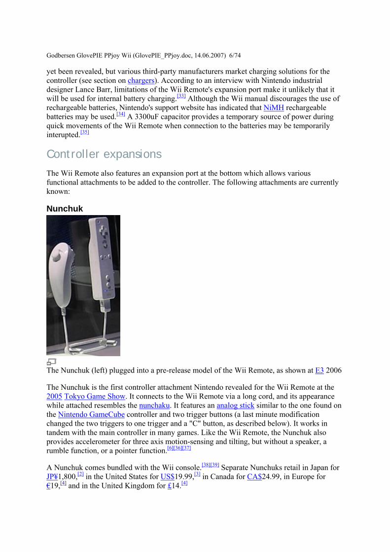
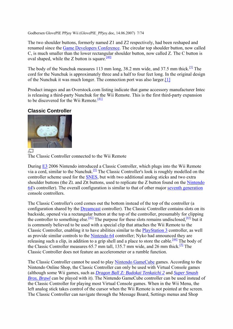
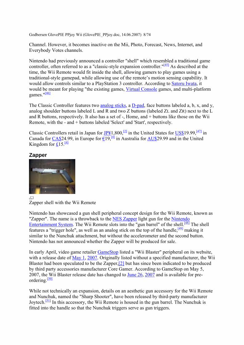
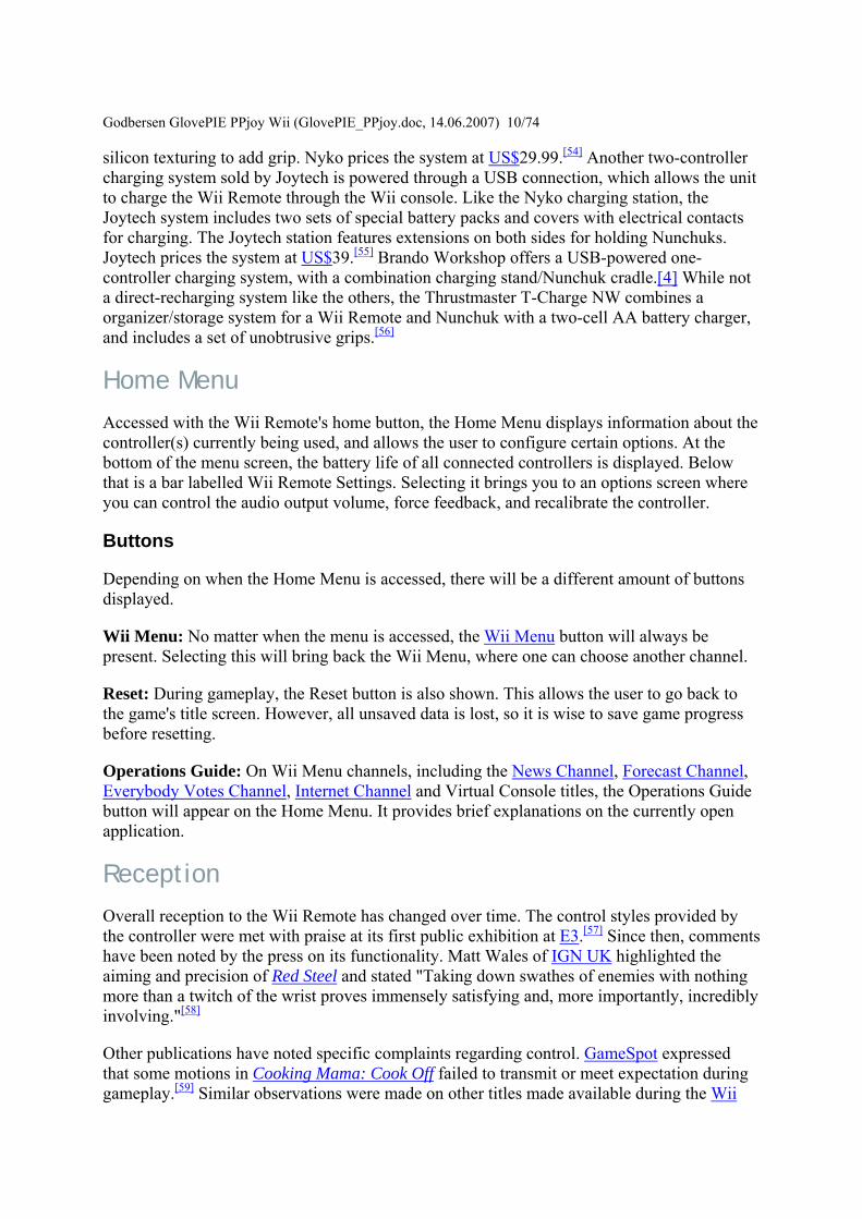
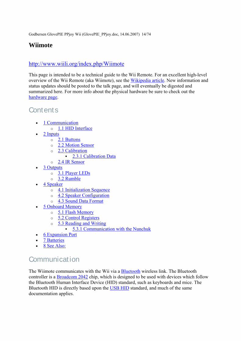
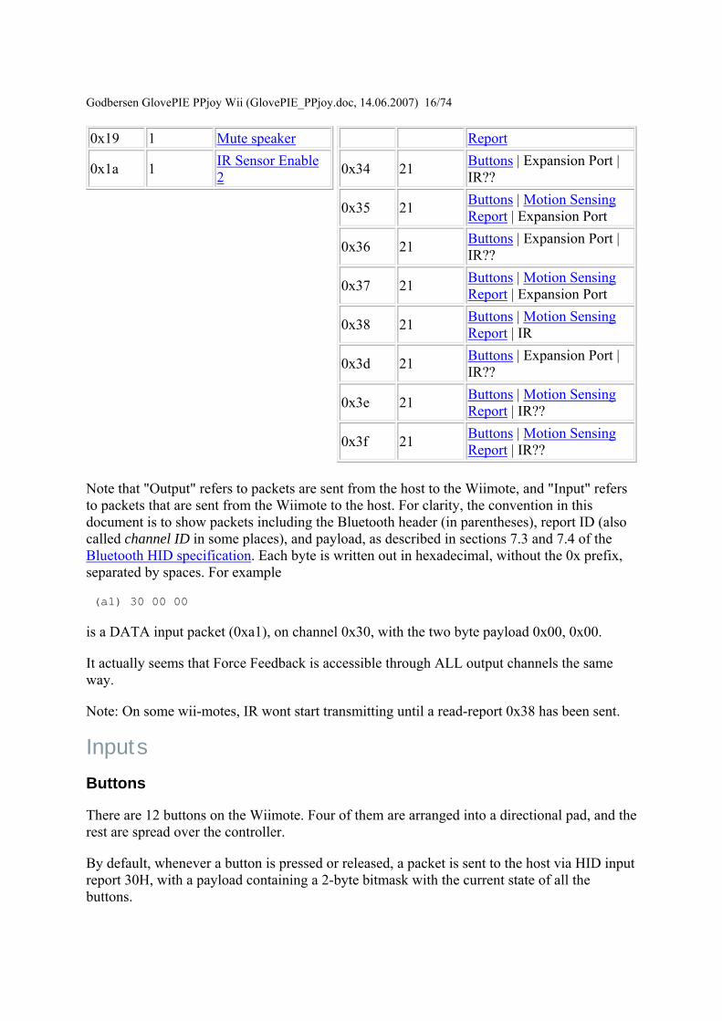
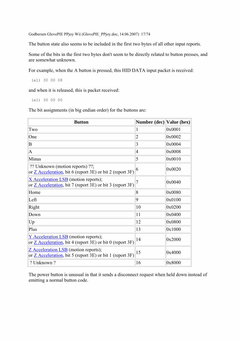
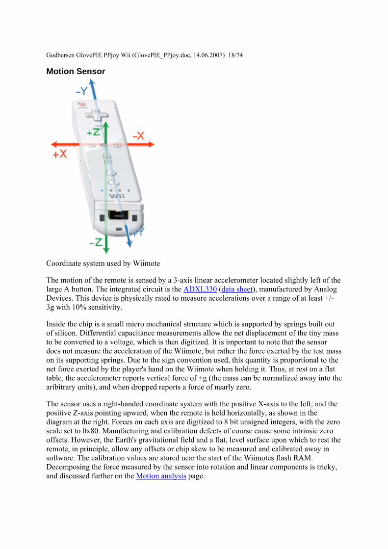
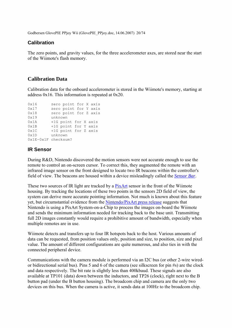
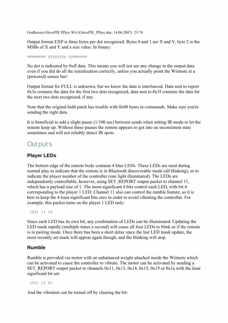
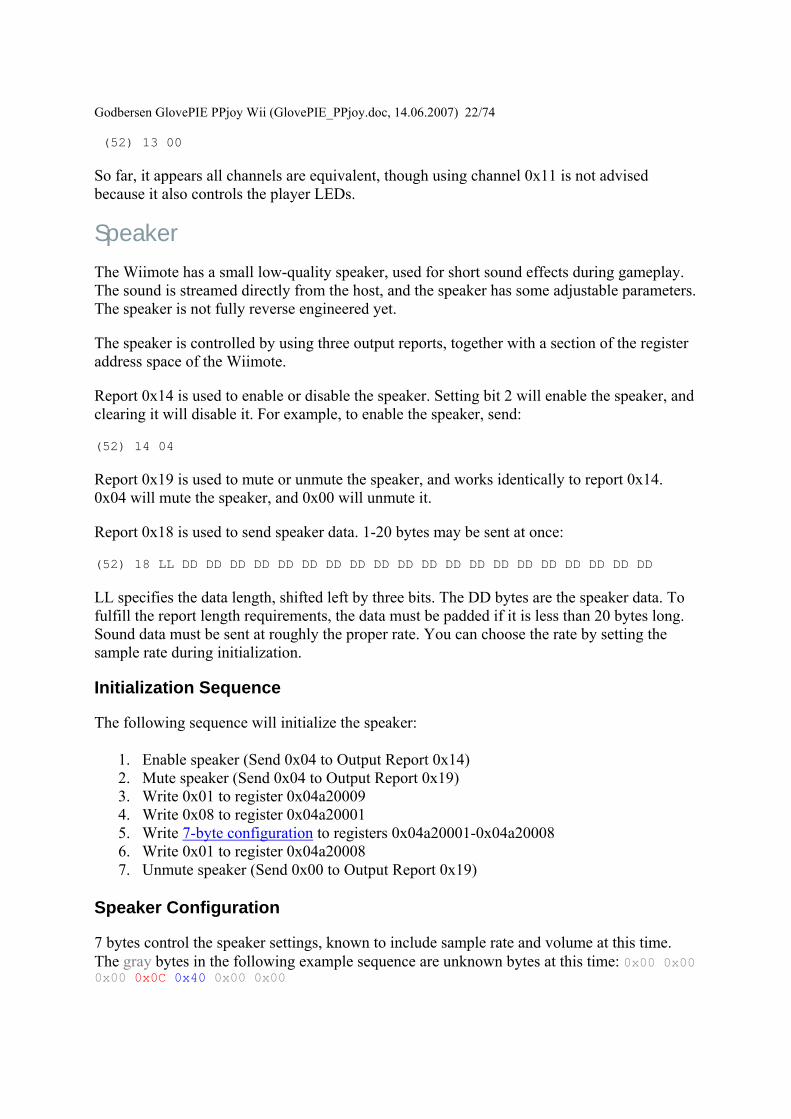
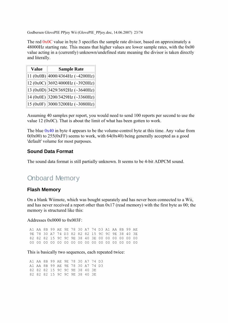
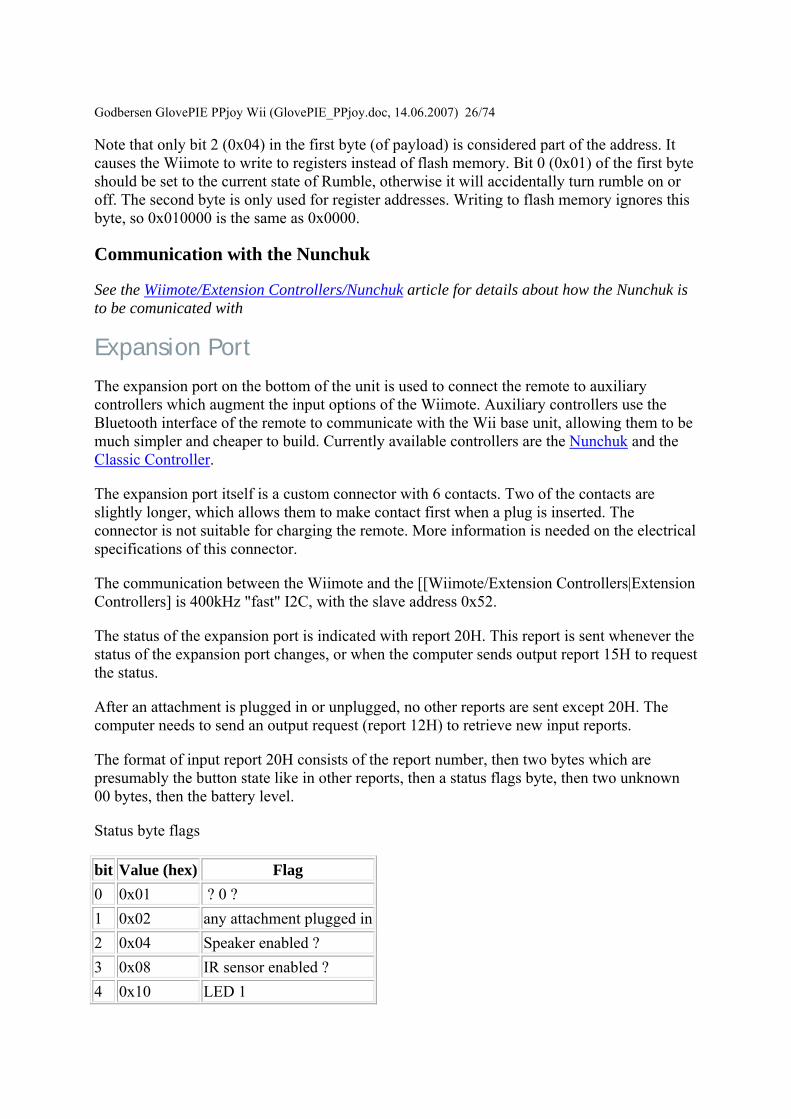
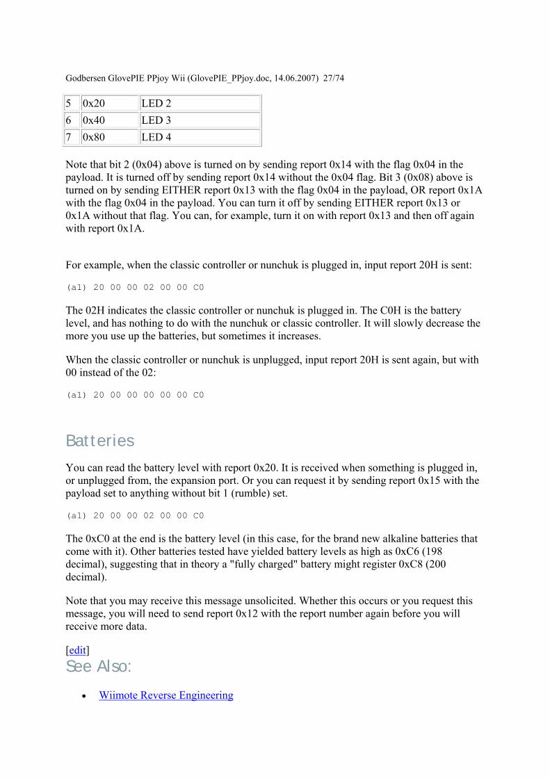
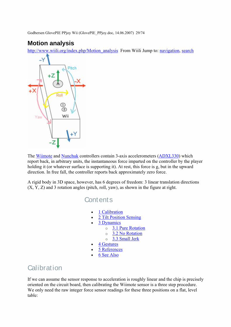
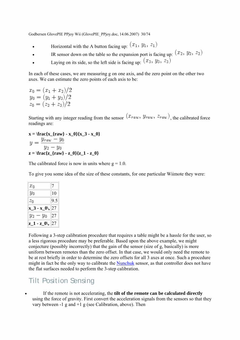
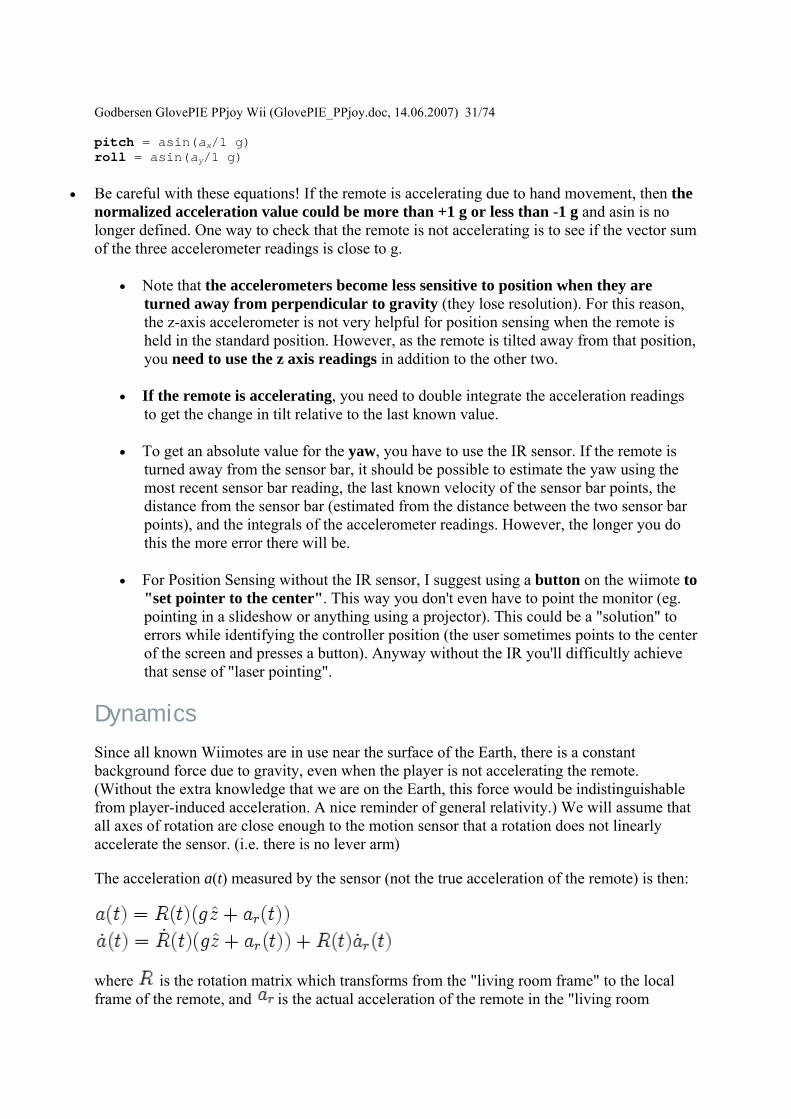
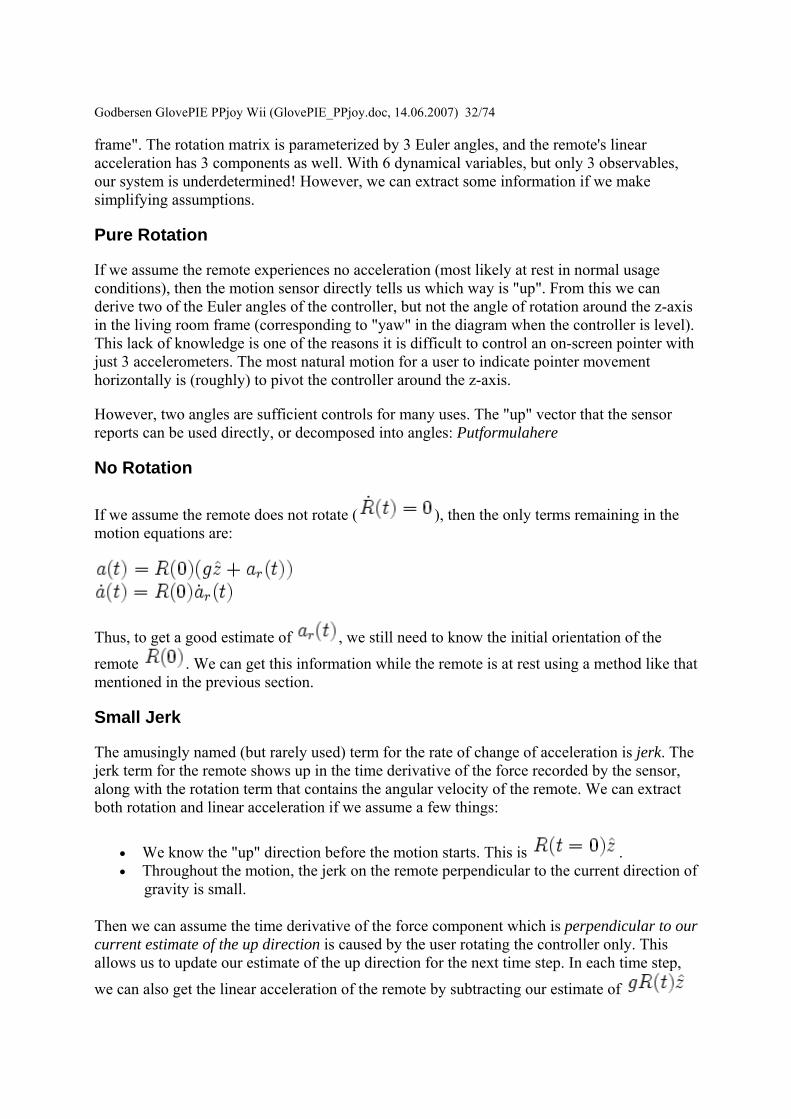
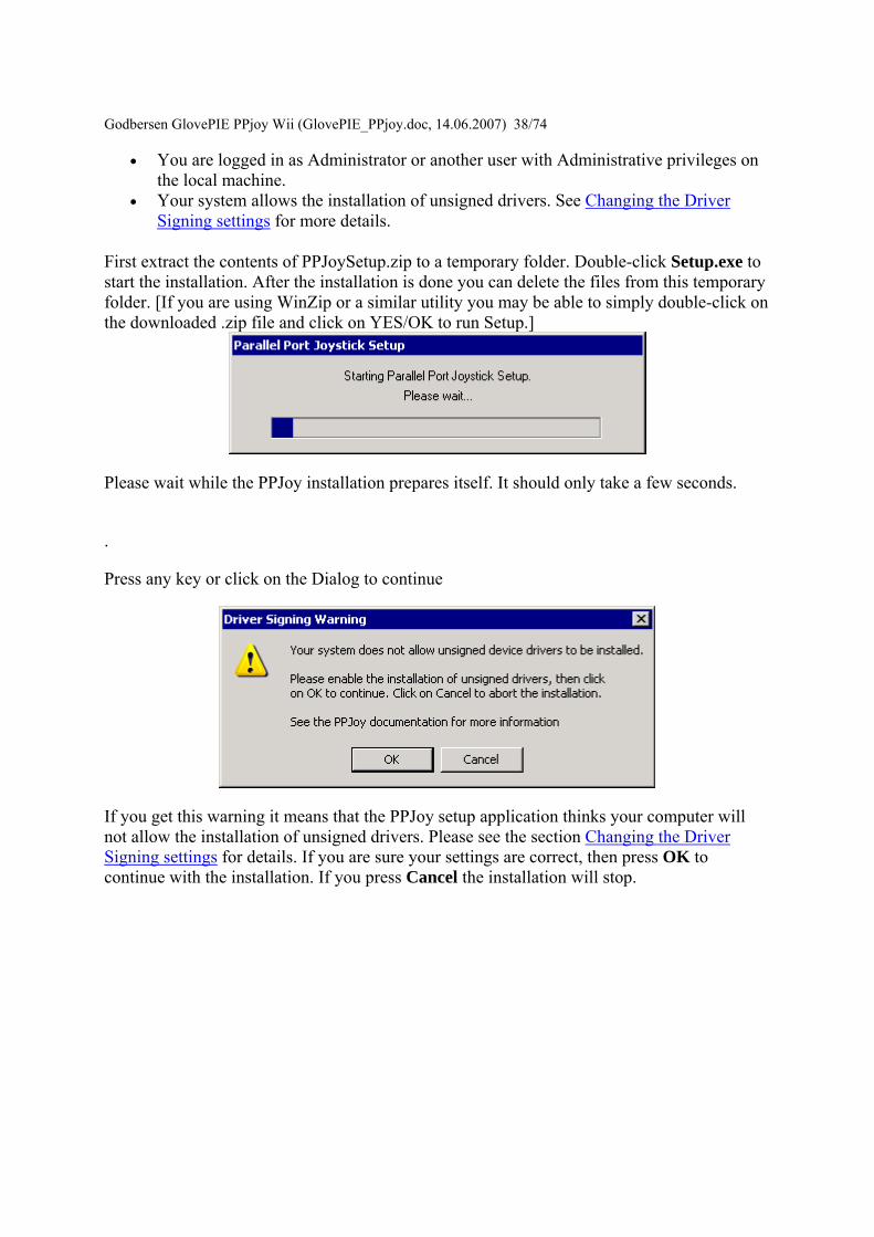
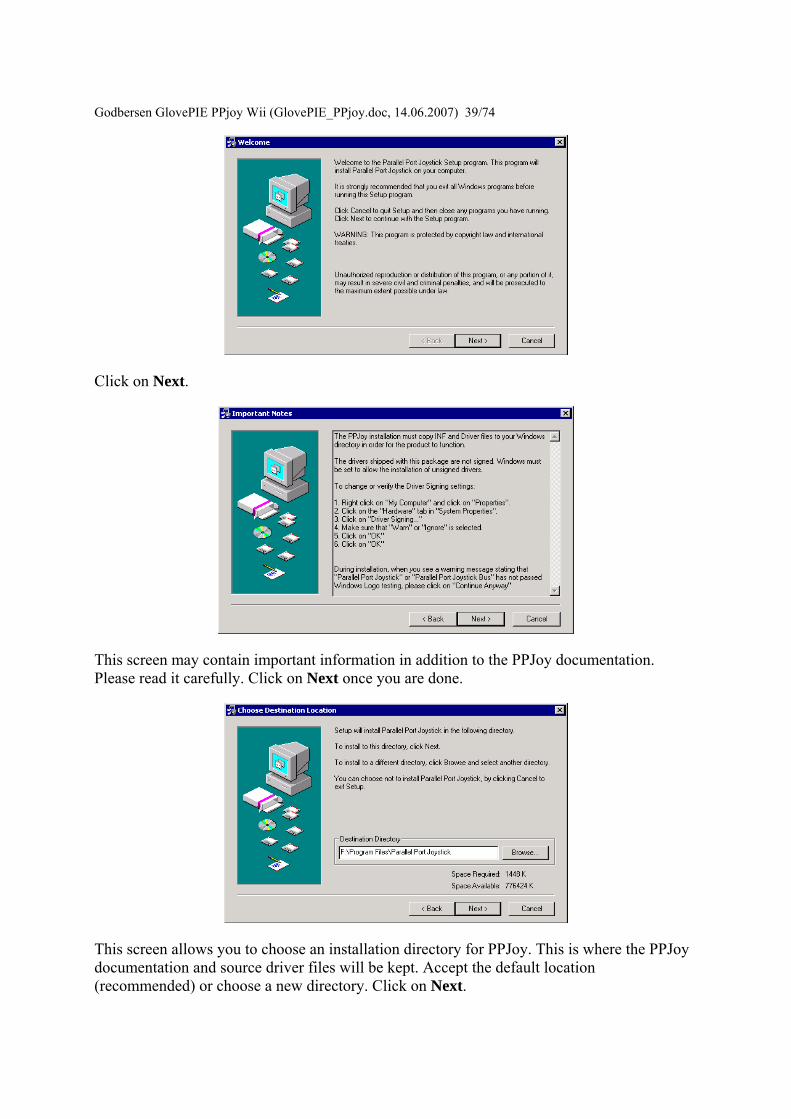
Godbersen GlovePIE
PPjoy Wii (GlovePIE_PPjoydoc 14062007) 3974
Click on Next
This screen may contain important information in addition to the PPJoy documentation Please read it carefully Click on Next once you are done
This screen allows you to choose an installation directory for PPJoy This is where the PPJoy documentation and source driver files will be kept Accept the default location (recommended) or choose a new directory Click on Next
Godbersen GlovePIE PPjo
y Wii (GlovePIE_PPjoydoc 14062007) 4074
This screen allows you to select the Program Folder on the Start Menu where the PPJoy files will be installed Accept the default folder (recommended) or choose a new folder Click on Next
This screen confirms that setup is ready to start the PPJoy installation Click on Next
This dialog shows the installation progress During this process Windows 2000 or Windows XP may show Unsigned Driver warning messages Please click on Yes (Windows 2000) or Continue Anyway (Windows XP) when these warning are shown
Godbersen GlovePIE PPjo
y Wii (GlovePIE_PPjoydoc 14062007) 4174
The PPJoy setup is complete Press Close to finish setup
Changing the Driver Signing settings Windows 2000 and XP have a new feature that controls the installation of unsigned device drivers There are three settings for Driver Signing
bull Block This will prevent the installation of unsigned drivers bull Warn This will prompt the user whether to install an unsigned device driver or not bull Ignore The system will install unsigned drivers without prompting the user
The PPJoy device drivers are unsigned and you will need to set your system to Warn or Ignore The rest of this document describes how to do that [Unsigned device drivers are drivers that are not certified and digitally signed by Microsoft They may impair your system performance It is up to you to decide if you want to take the risk or not]
First locate the My Computer icon on the desktop or in Windows Explorer Right-click on the My Computer icon and select Properties
Godbersen GlovePIE PPjoy W
ii (GlovePIE_PPjoydoc 14062007) 4274
Windows XP
After clicking on the Hardware tab your screen should look like one of the two screens shown above Now click on Driver Signing
Make sure that either Warn or Ignore is selected Then click on OK
Godbersen GlovePIE PPjoy Wii (GlovePIE_PPjoydoc 14062007) 4374
Unsigned Driver warning messages Warning screens for Windows XP If you see a screen similar to this one during installation or while adding a new joystick please click on Continue Anyway
Error screens for Windows XP If you see a screen like this one during installation your computer is not allowing unsigned drivers to be installed Please cancel the installation and review the information in Changing the Driver Signing settings
Godbersen GlovePIE PPjoy Wii (GlovePIE_PPjoydoc 14062007) 4474
Opening the PPJoy Control Panel applet This document describes how to open the PPJoy Control Panel applet The PPJoy applet is used to add and remove joysticks that are plugged into the Parallel Port
First click Start on the Taskbar then Settings and finally on Control Panel This will open the Control Panel
In Control Panel double-click on the Parallel Port Joysticks icon (shown highlighted) This will open the PPJoy Control Panel applet
Godbersen Glov
ePIE PPjoy Wii (GlovePIE_PPjoydoc 14062007) 4574
This is the main PPJoy applet window From this screen you will add and remove joysticks that are connected to the Parallel Port Joysticks that connect to the Gameport or USB will not show up here
If you get this error message instead of the PPJoy applet you need to make sure that PPJoyBussys is installed
Under Windows 98Me you need to install it yourself (see Windows 98 Post-Install actions) Under Windows 2000XP you need to make sure your settings allow the installation of unsigned drivers (see Driver signing for more information) and re-install the software
Adding a new joystick or gamepad This document describes how to add a new joystick or gamepad to PPJoy using the Control Panel applet See Opening the Control Panel applet for information on how to open the PPJoy control Panel applet
Godbersen Glov
ePIE PPjoy Wii (GlovePIE_PPjoydoc 14062007) 4674
To add a new controller click on the Add button in the PPJoy applet A new dialog box similar to the one below should appear
Or you may get this error message
Godbersen GlovePIE PPjo
y Wii (GlovePIE_PPjoydoc 14062007) 4774
PPJoy only supports 16 joysticks (due to a Windows limitation) and will give this error message when you try to add the 17th Joystick
First select the Parallel Port to which the joystick interface will be connected Only the ports on which new joysticks can be created will be shown The Virtual port is a special port that allows other applications to send joystick input via PPJoy
If there is only one port available it will be automatically selected and the field will be greyed out
Godbersen GlovePIE PPjoy Wii (GlovePIE_PPjoydoc 14062007) 4874 Next select the type of controller that is you want to connect to the particular port The interfaces available (see below) will depend on the selection made here The following controller types are currently supported
bull Joystick Standard digital joystick like on Commodore 64 Amstrad Spectrum etc or any other device that does not fit into the categories below
bull Genesis pad This is for Sega GenesisMegadrive controllers bull SNES or NES pad Nintendo NES SNES or Virtual Gameboy controllers bull Playstation pad Playstation or Playstation 2 controllers bull Virtual joystick Joystick device emulated by a Win32 application (minidriver)
Only the Virtual joystick device will only be shown when the Virtual Port is selected as parallel port The other device types will be shown for normal parallel ports
You cannot have more than one controller type or interface type on a single port If there are already joysticks defined for a given port the Controller Type and Interface Type will automatically be selected and greyed out
Next select the interface type that will be connected to the port This field will be greyed out if there is already an interface type defined for the selected port The list of interfaces shown are dependent on the Controller Type selected above
Note that the Controller Type and Interface Type together determines which physical interface is used For example the DirectPad Pro interface for the Playstation Pad Controller Type is very different from the DirectPad Pro interface for the Joystick Controller type
Godbersen GlovePIE
PPjoy Wii (GlovePIE_PPjoydoc 14062007) 4974
If the selected interface allows more than joystick to be connected (eg TurboGraFX or Linux0802) this field will allow you to choose the specific joystick If the interface only caters for one joystick this field will be greyed out
The last field allows you to select the specific type of controller connected if applicable
Currently the SNES or NES pad and Genesis pad controller type require a sub type to be specified because the sub types are read in different ways
Sub types for SNES or NES pad
bull SNES or Virtual Gameboy bull NES
Sub types for Genesis pad
bull ABC and Start This is the earlier Genesis pad
Godbersen GlovePIE PPjoy Wii (GlovePIE_PPjoydoc 14062007) 5074
bull ABCXYZ Start and Mode This is the later Genesis pad with 6 buttons
Click on Add to add the joystick to the system The screenshots shown below are from Windows XP the sequence for Windows 2000 is very similar On Windows 98Me you will need your original CD as Windows 98Me needs to install a driver from the CD
Make sure that Install the software automatically (as shown) are selected and click on Next
Click on Continue Anyway (Windows XP) or Yes (Windows 2000) if a warning appears about unsigned drivers This will depend on your settings for driver signing
Godbersen GlovePIE PPjoy W
ii (GlovePIE_PPjoydoc 14062007) 5174
Click on Finish
Make sure that Install the software automatically (as shown) are selected and click on Next
Click on Finish
Godbersen GlovePIE PPjoy Wii (GlovePIE_PPjoydoc 14062007) 5274
Removing an existing joystick This document describes how to remove an existing joystick using the PPJoy Control Panel applet See Opening the Control Panel applet for information on how to open the PPJoy control Panel applet
To delete a joystick select a joystick from the list displayed in the PPJoy applet then click on Remove Remove will only be enabled after you have selected a joystick from the list
There are two options when deleting a joystick
Remove joystick config from DirectInput should normally be ticked If it is not ticked the rest of Windows will think the joystick is simply unplugged It may also lead to failure when adding additional joysticks
Remove joystick driver from the system determines whether to delete the PPJoy device driver for the specified joystick It can safely be unchecked PPJoy uses a pool of up to 16 device drivers for the joysticks it emulates and can reuse the driver of a deleted joystick
Click on OK to confirm the deletion
Godbersen GlovePIE PPjoy Wii (GlovePIE_PPjoydoc 14062007) 5374
Changing button and axis the mapping PPJoy allows you to completely change the way the joystick buttons and axes configured The following topics will explain the mapping process in more detail
bull Important concepts bull Changing the button and axis mapping of a joystick bull Deleting a joystick mapping
Important concepts There are three levels of mapping in PPJoy
bull The Default mapping is used when there is no more specific (interface or individual) mapping for a particular joystick
bull The Interface mapping mapping applies to all joysticks without individual mappings that connect to this interface type
bull Individual mappings apply to a single joystick
If an individual mapping is defined for a joystick it will always be used If a joystick has no individual mapping the interface mapping will be used instead If there is no individual or interface mapping for a joystick the built-in default mapping will be used
The joystick mapping is used to transform the raw digital and analog values that PPJoy reads from a joystick into button presses axis movements and POV direction
bull Controls with an on-off motion are read as digital values All the buttons and the axes on most of the supported joysticks fall into this category
bull Controls with a range of motion are read as analog values Currently the Playstation controllers FMS PPM RC and the virtual joystick can return analog values
A button press can be mapped in the following ways
bull As a digital value read from a joystick bull When an analog control is moved to its minimum position bull When an analog control is moved to its maximum position bull As nothing in which case the button will never be pressed
An axis can be mapped in the following ways
bull Directly as an analog value read from a joystick bull Reverse of the analog value read from a joystick bull Two digital values one for minimum and one for the maximum axis position bull As nothing in which case the axis will always be centred
A POV hat can be mapped in three ways
bull As four directions These directional input can be any combination of button presses or axis minmax movements
Godbersen GlovePIE PPjoy Wii (GlovePIE_PPjoydoc 14062007) 5474
bull As a continuous direction between 0 and 359 degrees In this case a single analog input is used
bull As nothing in which case the POV hat will report not pressed
PPJoy allows you change the number of buttons and axes and POV hats reported for a joystick By default only the virtual joystick and PSX controllers have a POV hat defined
Changing the button and axis mapping of a joystick
Start by selecting the joystick to change and click on the Mapping button A new dialog box similar to the one below should appear
Godbersen Gl
ovePIE PPjoy Wii (GlovePIE_PPjoydoc 14062007) 5574
Broadly there are two groups of options the interface (top three) and individual (bottom three) options If no mapping exists for a given category (interface or individual) you are offered the chance to create a mapping else you have to option to modify or delete the mapping See the section Deleting a mapping for more information on how to delete a joystick mapping
The interface mapping will affect all controllers using that interface type unless the controller has its own individual mapping Individual mappings will always take precedence over interface mappings
If you choose a Set (Create) or Modify option and click on Next you will see the screen below
Godbersen Gl
ovePIE PPjoy Wii (GlovePIE_PPjoydoc 14062007) 5674
This screen will show you the number of buttons axes and hats that PPJoy will report to Windows for this device It will also show you the HID types reported for the axes You can change the number of axes buttons and hats reported to DirectX as well as their types Older verions of DirectX does not like this and will cause DrWatson errors in the Game Controllers Control Panel and possibly other applications as well Changing these values with DirectX 9 installed on Windows XP seems to work fine
Click on Next to continue
Godbersen Gl
ovePIE PPjoy Wii (GlovePIE_PPjoydoc 14062007) 5774
This screen will allow you to change the mapping for each axis Note that playstation pads have two mapping modes - digital and analog mode After configuring the mapping for digital mode you will be shown the same screens to configure the mapping for analog mode Currently all other devices only have a single mapping mode
An axis can be mapped in one of the following ways
bull Directly as an analog value read from a joystick for example an analog Playstation pad (Analog xx in the drop-down list)
bull An analog value read from a joystick with the direction reversed (Analog xx rev in the drop-down list)
bull Two digital values (buttons or digital joystick axes) one for minimum and one for the maximum axis position (Digital xx in the drop-down list)
bull As nothing in which case the axis will always be centred (nothing in the drop-down list)
The easiest way to set the mapping for a particular axis is to click on the Scan button in the Min column next to the axis you want to change The following screen will appear
Godbersen GlovePIE PPjoy Wii (G
lovePIE_PPjoydoc 14062007) 5874
Now press the button or move the control in the minimum (up left) direction that you want to map to this axis As soon as PPJoy senses any button press or axis movement on the selected device it will close the scan dialog and update the mapping page (If a button is pressed or an axis moved before clicking on the scan button the mapping page will immediately be updated and the scan dialog will not appear)
When an analog value is selected in the Min column for an axis the Max column for that axis will be greyed out This is because a single analog value completely defines an axis When a digital value is entered in the axis minimum column another digital value must be specified in the maximum column for that axis
Most interfaces will report the following values for up down left and right
bull D 0 Joystick is pressed UP bull D 1 Joystick is pressed DOWN bull D 2 Joystick is pressed LEFT bull D 3 Joystick is pressed RIGHT
When all the axis mappings are configured click on Next This takes you to the button mapping page
Godbersen Gl
ovePIE PPjoy Wii (GlovePIE_PPjoydoc 14062007) 5974
The button mapping page operates similar to the axis mapping page A button can be mapped in the following ways
bull Directly as digital value read from a joystick (Digital xx in the drop-down list) bull An analog value set to its minimum value (position) (Analog xx min in the drop-
down list) bull An analog value set to its maximum value (position) (Analog xx max in the drop-
down list) bull As nothing in which case the button will never be pressed (nothing in the drop-down
list)
The scan button operates the same as it does on the axis mapping page
Click on Next when you configured all the buttons If the device has more than 16 buttons you will be shown the button mapping page again this time for buttons 17 to (possibly) 32 otherwise you will proceed to the POV hat mapping page If there is no POV hat defined for the device this page is skipped
Godbersen Gl
ovePIE PPjoy Wii (GlovePIE_PPjoydoc 14062007) 6074
If you select a directional button POV you must provide a mapping for 4 buttons The mapping for these direction buttons works exactly like the mapping of (fire) buttons on the previous page
For a continuous position POV you must provide an analog input for the POV - you cannot use any digital inputs here Just like for axes you can use the analog value in its normal and reversed senses Take note that very few devices provides analog inputs
If this device has more than one configuration (like playstation pads) the Next button will take you to the axis mapping page for the next mapping After you have finished configuring the POV hats for the last mapping mode you will be moved on to the finish screen
Godbersen GlovePIE PPjo
y Wii (GlovePIE_PPjoydoc 14062007) 6174
This screen confirms that the mapping is complete It is also your last chance to cancel without writing the mapping to the joystick driver Click on Finish to write the new mapping to the driver
Deleting a joystick mapping
Godbersen Gl
ovePIE PPjoy Wii (GlovePIE_PPjoydoc 14062007) 6274
Start by selecting a joystick and clicking on the Mapping button
Select whether you want to delete the individual mapping for a joystick or the interface mapping Then click on Next If a mapping does not exist the option to delete it will be greyed out
Godbersen Gl
ovePIE PPjoy Wii (GlovePIE_PPjoydoc 14062007) 6374
This is the confirmation screen before the delete You have to select Yes before the Finish button will be activated After you selected Yes click on Finish
Changing the joystick interface timing parameters Certain joystick interfaces require relatively long delays which uses a lot of CPU cycles to read the joystick PPJoy allows you to customise the timing values used in order to minimize the CPU usage
Below is a list of the joystick and gamepad interfaces that have configurable timing parameters
bull Genesis gamepads bull NESSNES gamepads bull Playstation controllers bull LPT-switch controller bull FMS PPM RC transmitter
The following topics will explain changing timing parameters in more detail
bull Important concepts bull Changing the joystick timing parameters bull Deleting timing parameters
Godbersen GlovePIE PPjoy Wii (GlovePIE_PPjoydoc 14062007) 6474 Important concepts There are three levels of timing parameters in PPJoy
bull The Default timing is used when there are no more specific (interface or individual) timing parameters for a particular joystick They are probably not optimal for your controller but should be adequate in most cases
bull The Interface timing applies to all joysticks without individual timings that connect to this interface type
bull Individual timing applies to a single joystick
If individual timing parameters are defined for a joystick they will always be used If a joystick has no individual timing parameters the interface timing will be used instead If there is no individual or interface timing for a joystick the built-in default timing parameters will be used
Different interfaces even for the same controller type have separate interface timing settings For example the DirectPad Pro and Linux interfaces for Playstation controllers will each have their own interface timing parameters
Changing the joystick timing parameters
Start by selecting the joystick to change and click on the Timing button A new dialog box similar to the one below should appear
Godbersen Gl
ovePIE PPjoy Wii (GlovePIE_PPjoydoc 14062007) 6574
Broadly there are two groups of options the interface (top three) and individual (bottom three) options If no timing parameters exist for a given category (interface or individual) you are offered the chance to create new timing parameters else you have to option to modify or delete them See the section Deleting timing parameters for more information on how to delete the timing parameters
The interface timing parameters will affect all controllers using that interface type unless the controller has its own individual parameters Individual timing parameters will always take precedence over interface parameters
If you choose a Set (Create) or Modify option and click on Next you will see a screen like the one below The exact screen will depend on the joystick type for which you want to modify the timing parameters
Godbersen Gl
ovePIE PPjoy Wii (GlovePIE_PPjoydoc 14062007) 6674
The top part of the screen will list the timing parameters available for the selected controller or interface and allow you to change them Click on Apply to activate the new parameters while keeping the wizard open Clicking on Finish will apply the new timing values and close the wizard
The best strategy to configure timing parameters is probably to gradually lower and apply one parameter until the controllers operation becomes unstable Repeat this process for the other parameters
Clicking on Reset defaults will change the timing parameters back to the values they were when the wizard was started and apply them
Click on Finish after modifying the timing parameters
Godbersen Glov
ePIE PPjoy Wii (GlovePIE_PPjoydoc 14062007) 6774
Deleting timing parameters
Start by selecting a joystick and clicking on the Timing button
Godbersen Gl
ovePIE PPjoy Wii (GlovePIE_PPjoydoc 14062007) 6874
Select whether you want to delete the individual timing parameters for a joystick or the interface timing parameters Then click on Next If timing parameters do not exist the option to delete it will be greyed out
Godbersen Gl
ovePIE PPjoy Wii (GlovePIE_PPjoydoc 14062007) 6974
This is the confirmation screen before the delete You have to select Yes before the Finish button will be activated After you selected Yes click on Finish
Introduction This page provides information on the timing parameters available to tune the way PPJoy scans various controller types
The following controller types have customisable timing parameters
bull Sega Genesis controllers bull LPT-switch controllers bull PPM RC transmitters bull Playstation controllers bull SNESNES controllers
Sega Genesis controller timing parameters The timing parameters presented below are applicable to all Genesys interfaces
Godb
ersen GlovePIE PPjoy Wii (GlovePIE_PPjoydoc 14062007) 7074
There are two protocols used to Sega Genesis controllers The protocol used depends on the controller subtype specified when the controller was added If you specify ABC and Start as the controller type the 3-button protocol will be used if you specify ABCXYZ Start and Mode the 6-button protocol is used
bull Genesis interbit delay specifies the number of microseconds delay between changing the state of the Select line and reading the joystick state when using the 3-button protocol
bull Genesis 6 button interbit delay specifies the number of microseconds delay between changing the state of the Select line and reading the joystick state when using the 6-button protocol
LPT-switch controller timing parameters The timing parameters presented below are applicable to the LPT-switch interface
Godbersen Glov
ePIE PPjoy Wii (GlovePIE_PPjoydoc 14062007) 7174
The LPTswitch interface has a single timing parameter LPTswitch row select delay This parameter specifies the delay in microseconds between setting the row-select line low and reading the column data from the interface
PPM RC transmitter timing parameters The timing parameters presented below are applicable to the PPM RC transmitter interface
The PPM RC IRQ interface measures the durations between two consecutive low-to-high transitions of the IRQ pin This means that PPJoy does not care whether the timing pulses are high or low (Normal or Inverted signal)
The three applicable timing parameters are
bull PPM min servo pulse width specifies the minimum duration in microseconds between timing pulses If the duration between two consecutive pulses is less than this value the corresponding joystick axis will report its minimum position
bull PPM max servo pulse width specifies the maximum duration in microseconds between timing pulses If the duration between two consecutive pulses is more than this value but less than the minimum sync pulse width the corresponding joystick axis will report its maximum position
Godbersen GlovePIE PPjoy Wii (GlovePIE_PPjoydoc 14062007) 7274
bull PPM min sync pulse width specifies the minimum duration in microseconds of the sync pulse An inter-pulse duration greater than this value marks the beginning of a new frame
Playstation timing parameters The timing parameters presented below are applicable to Playstation interfaces
The figure above is timing for the transfer of an entire data packet The diagram below details the transfer of a single byte between the PC and PSX controller
There are five parameters for Playstation controllers
bull PSX Sel delay specifies the duration in microseconds that the select signal will be taken low before the first byte is transferred
bull PSX Bit delay specifies the duration in microseconds the delay between setting the clock signal high and writing a bit to the controller and between setting the clock line low and reading a bit from the controller
bull PSX Ack1 delay specifies the maximum duration in microseconds to wait for an ACK pulse from the controller after transferring the first byte to the controller
bull PSX AckX delay specifies the maximum duration in microseconds to wait for an ACK pulse from the controller after transferring the second or later byte to the controller
bull PSX Tail delay specifies the duration in microseconds that the Select signal will remain low after the packet transfer between the PC and controller is completed
Godb
ersen GlovePIE PPjoy Wii (GlovePIE_PPjoydoc 14062007) 7374
SNESNES timing parameters The timing parameters presented below are applicable to all SNESNESVirtual Gameboy interfaces
SNESNES interfaces have two timing parameters
bull SNES setup delay specifies the duration in microseconds that the latch signal will be held high
bull SNES interbit delay specifies the duration in microseconds between changes in the signal Every two bit delays an input bit will be read from the controller
Setting PPJoy global options PPJoy has a number of global options that affects the operation of one or more interfaces The options screen shown below can be activated by clicking on the Options button in the main PPJoy screen
Currently PPJoy supports the following options
bull Debug PPM RC interface Setting this option causes PPJoy to make a click (toggle speaker state) every time it detects an incoming pulse from PPM interface (LPT IRQ triggered) When the interface is working properly you should hear a steady tone
Godbersen GlovePIE PPjoy Wii (GlovePIE_PPjoydoc 14062007) 7474
bull Debug Playstation interfaces Setting this option causes PPJoy to make a click each time it reads an invalidcorrupted data packet from a playstation controller
bull Dont allocate ports to assigned joysticks This option only affects PPJoy on Windows 2000 XP and 2003 When it is set PPJoy acts the same way is does on Windows 98 Me where it does not allocate a parallel port when a joystick is configured Thus you do not have to disable PPJoy to use a printer connected to the parallel port
It is recommended that you do not turn on this option Turning on this option may interfere with printing and will also disable the PPM RC interface You need to restart your computer for changes to this option to take effect
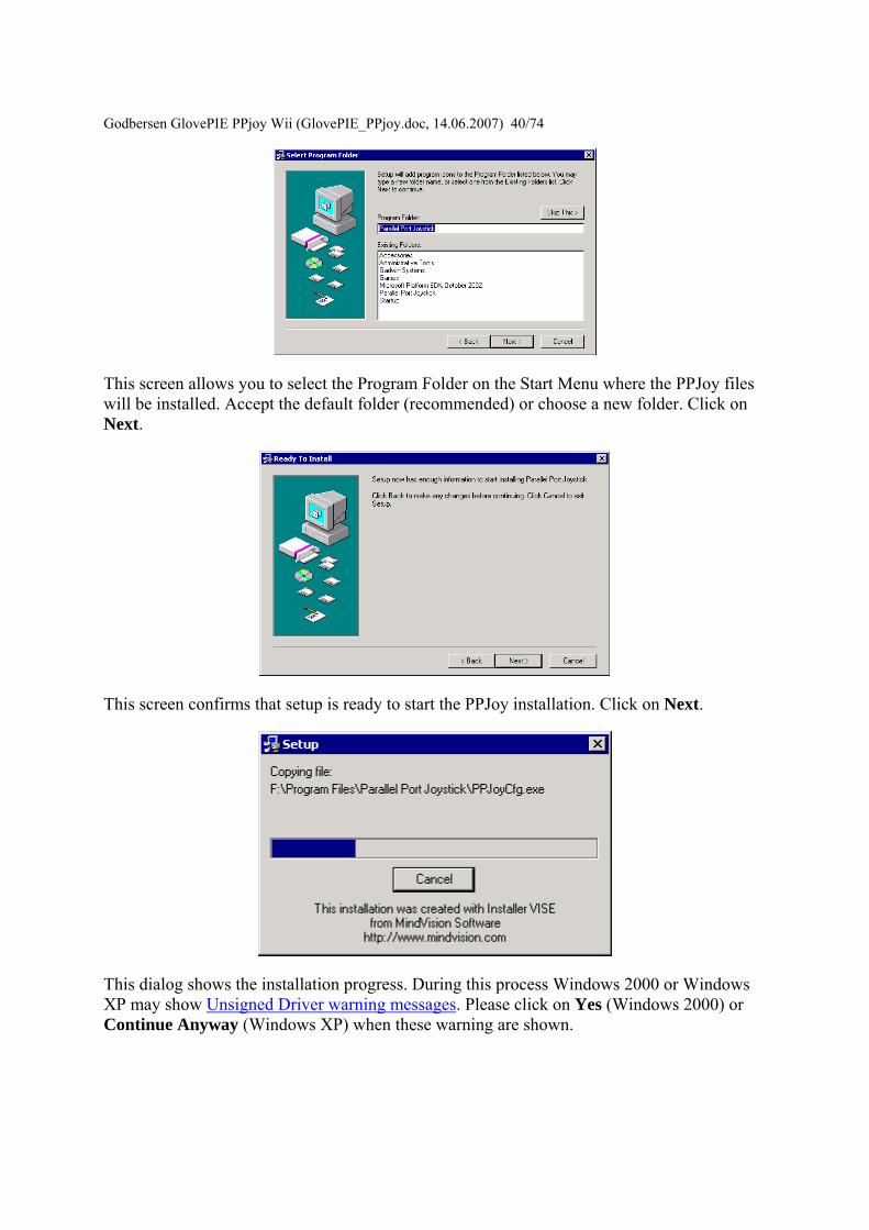
Godbersen GlovePIE PPjo
y Wii (GlovePIE_PPjoydoc 14062007) 4074
This screen allows you to select the Program Folder on the Start Menu where the PPJoy files will be installed Accept the default folder (recommended) or choose a new folder Click on Next
This screen confirms that setup is ready to start the PPJoy installation Click on Next
This dialog shows the installation progress During this process Windows 2000 or Windows XP may show Unsigned Driver warning messages Please click on Yes (Windows 2000) or Continue Anyway (Windows XP) when these warning are shown
Godbersen GlovePIE PPjo
y Wii (GlovePIE_PPjoydoc 14062007) 4174
The PPJoy setup is complete Press Close to finish setup
Changing the Driver Signing settings Windows 2000 and XP have a new feature that controls the installation of unsigned device drivers There are three settings for Driver Signing
bull Block This will prevent the installation of unsigned drivers bull Warn This will prompt the user whether to install an unsigned device driver or not bull Ignore The system will install unsigned drivers without prompting the user
The PPJoy device drivers are unsigned and you will need to set your system to Warn or Ignore The rest of this document describes how to do that [Unsigned device drivers are drivers that are not certified and digitally signed by Microsoft They may impair your system performance It is up to you to decide if you want to take the risk or not]
First locate the My Computer icon on the desktop or in Windows Explorer Right-click on the My Computer icon and select Properties
Godbersen GlovePIE PPjoy W
ii (GlovePIE_PPjoydoc 14062007) 4274
Windows XP
After clicking on the Hardware tab your screen should look like one of the two screens shown above Now click on Driver Signing
Make sure that either Warn or Ignore is selected Then click on OK
Godbersen GlovePIE PPjoy Wii (GlovePIE_PPjoydoc 14062007) 4374
Unsigned Driver warning messages Warning screens for Windows XP If you see a screen similar to this one during installation or while adding a new joystick please click on Continue Anyway
Error screens for Windows XP If you see a screen like this one during installation your computer is not allowing unsigned drivers to be installed Please cancel the installation and review the information in Changing the Driver Signing settings
Godbersen GlovePIE PPjoy Wii (GlovePIE_PPjoydoc 14062007) 4474
Opening the PPJoy Control Panel applet This document describes how to open the PPJoy Control Panel applet The PPJoy applet is used to add and remove joysticks that are plugged into the Parallel Port
First click Start on the Taskbar then Settings and finally on Control Panel This will open the Control Panel
In Control Panel double-click on the Parallel Port Joysticks icon (shown highlighted) This will open the PPJoy Control Panel applet
Godbersen Glov
ePIE PPjoy Wii (GlovePIE_PPjoydoc 14062007) 4574
This is the main PPJoy applet window From this screen you will add and remove joysticks that are connected to the Parallel Port Joysticks that connect to the Gameport or USB will not show up here
If you get this error message instead of the PPJoy applet you need to make sure that PPJoyBussys is installed
Under Windows 98Me you need to install it yourself (see Windows 98 Post-Install actions) Under Windows 2000XP you need to make sure your settings allow the installation of unsigned drivers (see Driver signing for more information) and re-install the software
Adding a new joystick or gamepad This document describes how to add a new joystick or gamepad to PPJoy using the Control Panel applet See Opening the Control Panel applet for information on how to open the PPJoy control Panel applet
Godbersen Glov
ePIE PPjoy Wii (GlovePIE_PPjoydoc 14062007) 4674
To add a new controller click on the Add button in the PPJoy applet A new dialog box similar to the one below should appear
Or you may get this error message
Godbersen GlovePIE PPjo
y Wii (GlovePIE_PPjoydoc 14062007) 4774
PPJoy only supports 16 joysticks (due to a Windows limitation) and will give this error message when you try to add the 17th Joystick
First select the Parallel Port to which the joystick interface will be connected Only the ports on which new joysticks can be created will be shown The Virtual port is a special port that allows other applications to send joystick input via PPJoy
If there is only one port available it will be automatically selected and the field will be greyed out
Godbersen GlovePIE PPjoy Wii (GlovePIE_PPjoydoc 14062007) 4874 Next select the type of controller that is you want to connect to the particular port The interfaces available (see below) will depend on the selection made here The following controller types are currently supported
bull Joystick Standard digital joystick like on Commodore 64 Amstrad Spectrum etc or any other device that does not fit into the categories below
bull Genesis pad This is for Sega GenesisMegadrive controllers bull SNES or NES pad Nintendo NES SNES or Virtual Gameboy controllers bull Playstation pad Playstation or Playstation 2 controllers bull Virtual joystick Joystick device emulated by a Win32 application (minidriver)
Only the Virtual joystick device will only be shown when the Virtual Port is selected as parallel port The other device types will be shown for normal parallel ports
You cannot have more than one controller type or interface type on a single port If there are already joysticks defined for a given port the Controller Type and Interface Type will automatically be selected and greyed out
Next select the interface type that will be connected to the port This field will be greyed out if there is already an interface type defined for the selected port The list of interfaces shown are dependent on the Controller Type selected above
Note that the Controller Type and Interface Type together determines which physical interface is used For example the DirectPad Pro interface for the Playstation Pad Controller Type is very different from the DirectPad Pro interface for the Joystick Controller type
Godbersen GlovePIE
PPjoy Wii (GlovePIE_PPjoydoc 14062007) 4974
If the selected interface allows more than joystick to be connected (eg TurboGraFX or Linux0802) this field will allow you to choose the specific joystick If the interface only caters for one joystick this field will be greyed out
The last field allows you to select the specific type of controller connected if applicable
Currently the SNES or NES pad and Genesis pad controller type require a sub type to be specified because the sub types are read in different ways
Sub types for SNES or NES pad
bull SNES or Virtual Gameboy bull NES
Sub types for Genesis pad
bull ABC and Start This is the earlier Genesis pad
Godbersen GlovePIE PPjoy Wii (GlovePIE_PPjoydoc 14062007) 5074
bull ABCXYZ Start and Mode This is the later Genesis pad with 6 buttons
Click on Add to add the joystick to the system The screenshots shown below are from Windows XP the sequence for Windows 2000 is very similar On Windows 98Me you will need your original CD as Windows 98Me needs to install a driver from the CD
Make sure that Install the software automatically (as shown) are selected and click on Next
Click on Continue Anyway (Windows XP) or Yes (Windows 2000) if a warning appears about unsigned drivers This will depend on your settings for driver signing
Godbersen GlovePIE PPjoy W
ii (GlovePIE_PPjoydoc 14062007) 5174
Click on Finish
Make sure that Install the software automatically (as shown) are selected and click on Next
Click on Finish
Godbersen GlovePIE PPjoy Wii (GlovePIE_PPjoydoc 14062007) 5274
Removing an existing joystick This document describes how to remove an existing joystick using the PPJoy Control Panel applet See Opening the Control Panel applet for information on how to open the PPJoy control Panel applet
To delete a joystick select a joystick from the list displayed in the PPJoy applet then click on Remove Remove will only be enabled after you have selected a joystick from the list
There are two options when deleting a joystick
Remove joystick config from DirectInput should normally be ticked If it is not ticked the rest of Windows will think the joystick is simply unplugged It may also lead to failure when adding additional joysticks
Remove joystick driver from the system determines whether to delete the PPJoy device driver for the specified joystick It can safely be unchecked PPJoy uses a pool of up to 16 device drivers for the joysticks it emulates and can reuse the driver of a deleted joystick
Click on OK to confirm the deletion
Godbersen GlovePIE PPjoy Wii (GlovePIE_PPjoydoc 14062007) 5374
Changing button and axis the mapping PPJoy allows you to completely change the way the joystick buttons and axes configured The following topics will explain the mapping process in more detail
bull Important concepts bull Changing the button and axis mapping of a joystick bull Deleting a joystick mapping
Important concepts There are three levels of mapping in PPJoy
bull The Default mapping is used when there is no more specific (interface or individual) mapping for a particular joystick
bull The Interface mapping mapping applies to all joysticks without individual mappings that connect to this interface type
bull Individual mappings apply to a single joystick
If an individual mapping is defined for a joystick it will always be used If a joystick has no individual mapping the interface mapping will be used instead If there is no individual or interface mapping for a joystick the built-in default mapping will be used
The joystick mapping is used to transform the raw digital and analog values that PPJoy reads from a joystick into button presses axis movements and POV direction
bull Controls with an on-off motion are read as digital values All the buttons and the axes on most of the supported joysticks fall into this category
bull Controls with a range of motion are read as analog values Currently the Playstation controllers FMS PPM RC and the virtual joystick can return analog values
A button press can be mapped in the following ways
bull As a digital value read from a joystick bull When an analog control is moved to its minimum position bull When an analog control is moved to its maximum position bull As nothing in which case the button will never be pressed
An axis can be mapped in the following ways
bull Directly as an analog value read from a joystick bull Reverse of the analog value read from a joystick bull Two digital values one for minimum and one for the maximum axis position bull As nothing in which case the axis will always be centred
A POV hat can be mapped in three ways
bull As four directions These directional input can be any combination of button presses or axis minmax movements
Godbersen GlovePIE PPjoy Wii (GlovePIE_PPjoydoc 14062007) 5474
bull As a continuous direction between 0 and 359 degrees In this case a single analog input is used
bull As nothing in which case the POV hat will report not pressed
PPJoy allows you change the number of buttons and axes and POV hats reported for a joystick By default only the virtual joystick and PSX controllers have a POV hat defined
Changing the button and axis mapping of a joystick
Start by selecting the joystick to change and click on the Mapping button A new dialog box similar to the one below should appear
Godbersen Gl
ovePIE PPjoy Wii (GlovePIE_PPjoydoc 14062007) 5574
Broadly there are two groups of options the interface (top three) and individual (bottom three) options If no mapping exists for a given category (interface or individual) you are offered the chance to create a mapping else you have to option to modify or delete the mapping See the section Deleting a mapping for more information on how to delete a joystick mapping
The interface mapping will affect all controllers using that interface type unless the controller has its own individual mapping Individual mappings will always take precedence over interface mappings
If you choose a Set (Create) or Modify option and click on Next you will see the screen below
Godbersen Gl
ovePIE PPjoy Wii (GlovePIE_PPjoydoc 14062007) 5674
This screen will show you the number of buttons axes and hats that PPJoy will report to Windows for this device It will also show you the HID types reported for the axes You can change the number of axes buttons and hats reported to DirectX as well as their types Older verions of DirectX does not like this and will cause DrWatson errors in the Game Controllers Control Panel and possibly other applications as well Changing these values with DirectX 9 installed on Windows XP seems to work fine
Click on Next to continue
Godbersen Gl
ovePIE PPjoy Wii (GlovePIE_PPjoydoc 14062007) 5774
This screen will allow you to change the mapping for each axis Note that playstation pads have two mapping modes - digital and analog mode After configuring the mapping for digital mode you will be shown the same screens to configure the mapping for analog mode Currently all other devices only have a single mapping mode
An axis can be mapped in one of the following ways
bull Directly as an analog value read from a joystick for example an analog Playstation pad (Analog xx in the drop-down list)
bull An analog value read from a joystick with the direction reversed (Analog xx rev in the drop-down list)
bull Two digital values (buttons or digital joystick axes) one for minimum and one for the maximum axis position (Digital xx in the drop-down list)
bull As nothing in which case the axis will always be centred (nothing in the drop-down list)
The easiest way to set the mapping for a particular axis is to click on the Scan button in the Min column next to the axis you want to change The following screen will appear
Godbersen GlovePIE PPjoy Wii (G
lovePIE_PPjoydoc 14062007) 5874
Now press the button or move the control in the minimum (up left) direction that you want to map to this axis As soon as PPJoy senses any button press or axis movement on the selected device it will close the scan dialog and update the mapping page (If a button is pressed or an axis moved before clicking on the scan button the mapping page will immediately be updated and the scan dialog will not appear)
When an analog value is selected in the Min column for an axis the Max column for that axis will be greyed out This is because a single analog value completely defines an axis When a digital value is entered in the axis minimum column another digital value must be specified in the maximum column for that axis
Most interfaces will report the following values for up down left and right
bull D 0 Joystick is pressed UP bull D 1 Joystick is pressed DOWN bull D 2 Joystick is pressed LEFT bull D 3 Joystick is pressed RIGHT
When all the axis mappings are configured click on Next This takes you to the button mapping page
Godbersen Gl
ovePIE PPjoy Wii (GlovePIE_PPjoydoc 14062007) 5974
The button mapping page operates similar to the axis mapping page A button can be mapped in the following ways
bull Directly as digital value read from a joystick (Digital xx in the drop-down list) bull An analog value set to its minimum value (position) (Analog xx min in the drop-
down list) bull An analog value set to its maximum value (position) (Analog xx max in the drop-
down list) bull As nothing in which case the button will never be pressed (nothing in the drop-down
list)
The scan button operates the same as it does on the axis mapping page
Click on Next when you configured all the buttons If the device has more than 16 buttons you will be shown the button mapping page again this time for buttons 17 to (possibly) 32 otherwise you will proceed to the POV hat mapping page If there is no POV hat defined for the device this page is skipped
Godbersen Gl
ovePIE PPjoy Wii (GlovePIE_PPjoydoc 14062007) 6074
If you select a directional button POV you must provide a mapping for 4 buttons The mapping for these direction buttons works exactly like the mapping of (fire) buttons on the previous page
For a continuous position POV you must provide an analog input for the POV - you cannot use any digital inputs here Just like for axes you can use the analog value in its normal and reversed senses Take note that very few devices provides analog inputs
If this device has more than one configuration (like playstation pads) the Next button will take you to the axis mapping page for the next mapping After you have finished configuring the POV hats for the last mapping mode you will be moved on to the finish screen
Godbersen GlovePIE PPjo
y Wii (GlovePIE_PPjoydoc 14062007) 6174
This screen confirms that the mapping is complete It is also your last chance to cancel without writing the mapping to the joystick driver Click on Finish to write the new mapping to the driver
Deleting a joystick mapping
Godbersen Gl
ovePIE PPjoy Wii (GlovePIE_PPjoydoc 14062007) 6274
Start by selecting a joystick and clicking on the Mapping button
Select whether you want to delete the individual mapping for a joystick or the interface mapping Then click on Next If a mapping does not exist the option to delete it will be greyed out
Godbersen Gl
ovePIE PPjoy Wii (GlovePIE_PPjoydoc 14062007) 6374
This is the confirmation screen before the delete You have to select Yes before the Finish button will be activated After you selected Yes click on Finish
Changing the joystick interface timing parameters Certain joystick interfaces require relatively long delays which uses a lot of CPU cycles to read the joystick PPJoy allows you to customise the timing values used in order to minimize the CPU usage
Below is a list of the joystick and gamepad interfaces that have configurable timing parameters
bull Genesis gamepads bull NESSNES gamepads bull Playstation controllers bull LPT-switch controller bull FMS PPM RC transmitter
The following topics will explain changing timing parameters in more detail
bull Important concepts bull Changing the joystick timing parameters bull Deleting timing parameters
Godbersen GlovePIE PPjoy Wii (GlovePIE_PPjoydoc 14062007) 6474 Important concepts There are three levels of timing parameters in PPJoy
bull The Default timing is used when there are no more specific (interface or individual) timing parameters for a particular joystick They are probably not optimal for your controller but should be adequate in most cases
bull The Interface timing applies to all joysticks without individual timings that connect to this interface type
bull Individual timing applies to a single joystick
If individual timing parameters are defined for a joystick they will always be used If a joystick has no individual timing parameters the interface timing will be used instead If there is no individual or interface timing for a joystick the built-in default timing parameters will be used
Different interfaces even for the same controller type have separate interface timing settings For example the DirectPad Pro and Linux interfaces for Playstation controllers will each have their own interface timing parameters
Changing the joystick timing parameters
Start by selecting the joystick to change and click on the Timing button A new dialog box similar to the one below should appear
Godbersen Gl
ovePIE PPjoy Wii (GlovePIE_PPjoydoc 14062007) 6574
Broadly there are two groups of options the interface (top three) and individual (bottom three) options If no timing parameters exist for a given category (interface or individual) you are offered the chance to create new timing parameters else you have to option to modify or delete them See the section Deleting timing parameters for more information on how to delete the timing parameters
The interface timing parameters will affect all controllers using that interface type unless the controller has its own individual parameters Individual timing parameters will always take precedence over interface parameters
If you choose a Set (Create) or Modify option and click on Next you will see a screen like the one below The exact screen will depend on the joystick type for which you want to modify the timing parameters
Godbersen Gl
ovePIE PPjoy Wii (GlovePIE_PPjoydoc 14062007) 6674
The top part of the screen will list the timing parameters available for the selected controller or interface and allow you to change them Click on Apply to activate the new parameters while keeping the wizard open Clicking on Finish will apply the new timing values and close the wizard
The best strategy to configure timing parameters is probably to gradually lower and apply one parameter until the controllers operation becomes unstable Repeat this process for the other parameters
Clicking on Reset defaults will change the timing parameters back to the values they were when the wizard was started and apply them
Click on Finish after modifying the timing parameters
Godbersen Glov
ePIE PPjoy Wii (GlovePIE_PPjoydoc 14062007) 6774
Deleting timing parameters
Start by selecting a joystick and clicking on the Timing button
Godbersen Gl
ovePIE PPjoy Wii (GlovePIE_PPjoydoc 14062007) 6874
Select whether you want to delete the individual timing parameters for a joystick or the interface timing parameters Then click on Next If timing parameters do not exist the option to delete it will be greyed out
Godbersen Gl
ovePIE PPjoy Wii (GlovePIE_PPjoydoc 14062007) 6974
This is the confirmation screen before the delete You have to select Yes before the Finish button will be activated After you selected Yes click on Finish
Introduction This page provides information on the timing parameters available to tune the way PPJoy scans various controller types
The following controller types have customisable timing parameters
bull Sega Genesis controllers bull LPT-switch controllers bull PPM RC transmitters bull Playstation controllers bull SNESNES controllers
Sega Genesis controller timing parameters The timing parameters presented below are applicable to all Genesys interfaces
Godb
ersen GlovePIE PPjoy Wii (GlovePIE_PPjoydoc 14062007) 7074
There are two protocols used to Sega Genesis controllers The protocol used depends on the controller subtype specified when the controller was added If you specify ABC and Start as the controller type the 3-button protocol will be used if you specify ABCXYZ Start and Mode the 6-button protocol is used
bull Genesis interbit delay specifies the number of microseconds delay between changing the state of the Select line and reading the joystick state when using the 3-button protocol
bull Genesis 6 button interbit delay specifies the number of microseconds delay between changing the state of the Select line and reading the joystick state when using the 6-button protocol
LPT-switch controller timing parameters The timing parameters presented below are applicable to the LPT-switch interface
Godbersen Glov
ePIE PPjoy Wii (GlovePIE_PPjoydoc 14062007) 7174
The LPTswitch interface has a single timing parameter LPTswitch row select delay This parameter specifies the delay in microseconds between setting the row-select line low and reading the column data from the interface
PPM RC transmitter timing parameters The timing parameters presented below are applicable to the PPM RC transmitter interface
The PPM RC IRQ interface measures the durations between two consecutive low-to-high transitions of the IRQ pin This means that PPJoy does not care whether the timing pulses are high or low (Normal or Inverted signal)
The three applicable timing parameters are
bull PPM min servo pulse width specifies the minimum duration in microseconds between timing pulses If the duration between two consecutive pulses is less than this value the corresponding joystick axis will report its minimum position
bull PPM max servo pulse width specifies the maximum duration in microseconds between timing pulses If the duration between two consecutive pulses is more than this value but less than the minimum sync pulse width the corresponding joystick axis will report its maximum position
Godbersen GlovePIE PPjoy Wii (GlovePIE_PPjoydoc 14062007) 7274
bull PPM min sync pulse width specifies the minimum duration in microseconds of the sync pulse An inter-pulse duration greater than this value marks the beginning of a new frame
Playstation timing parameters The timing parameters presented below are applicable to Playstation interfaces
The figure above is timing for the transfer of an entire data packet The diagram below details the transfer of a single byte between the PC and PSX controller
There are five parameters for Playstation controllers
bull PSX Sel delay specifies the duration in microseconds that the select signal will be taken low before the first byte is transferred
bull PSX Bit delay specifies the duration in microseconds the delay between setting the clock signal high and writing a bit to the controller and between setting the clock line low and reading a bit from the controller
bull PSX Ack1 delay specifies the maximum duration in microseconds to wait for an ACK pulse from the controller after transferring the first byte to the controller
bull PSX AckX delay specifies the maximum duration in microseconds to wait for an ACK pulse from the controller after transferring the second or later byte to the controller
bull PSX Tail delay specifies the duration in microseconds that the Select signal will remain low after the packet transfer between the PC and controller is completed
Godb
ersen GlovePIE PPjoy Wii (GlovePIE_PPjoydoc 14062007) 7374
SNESNES timing parameters The timing parameters presented below are applicable to all SNESNESVirtual Gameboy interfaces
SNESNES interfaces have two timing parameters
bull SNES setup delay specifies the duration in microseconds that the latch signal will be held high
bull SNES interbit delay specifies the duration in microseconds between changes in the signal Every two bit delays an input bit will be read from the controller
Setting PPJoy global options PPJoy has a number of global options that affects the operation of one or more interfaces The options screen shown below can be activated by clicking on the Options button in the main PPJoy screen
Currently PPJoy supports the following options
bull Debug PPM RC interface Setting this option causes PPJoy to make a click (toggle speaker state) every time it detects an incoming pulse from PPM interface (LPT IRQ triggered) When the interface is working properly you should hear a steady tone
Godbersen GlovePIE PPjoy Wii (GlovePIE_PPjoydoc 14062007) 7474
bull Debug Playstation interfaces Setting this option causes PPJoy to make a click each time it reads an invalidcorrupted data packet from a playstation controller
bull Dont allocate ports to assigned joysticks This option only affects PPJoy on Windows 2000 XP and 2003 When it is set PPJoy acts the same way is does on Windows 98 Me where it does not allocate a parallel port when a joystick is configured Thus you do not have to disable PPJoy to use a printer connected to the parallel port
It is recommended that you do not turn on this option Turning on this option may interfere with printing and will also disable the PPM RC interface You need to restart your computer for changes to this option to take effect
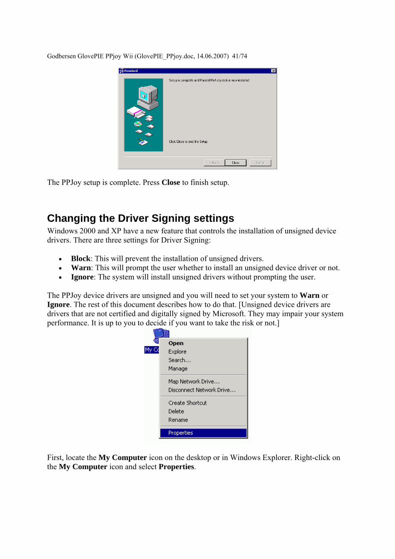
Godbersen GlovePIE PPjo
y Wii (GlovePIE_PPjoydoc 14062007) 4174
The PPJoy setup is complete Press Close to finish setup
Changing the Driver Signing settings Windows 2000 and XP have a new feature that controls the installation of unsigned device drivers There are three settings for Driver Signing
bull Block This will prevent the installation of unsigned drivers bull Warn This will prompt the user whether to install an unsigned device driver or not bull Ignore The system will install unsigned drivers without prompting the user
The PPJoy device drivers are unsigned and you will need to set your system to Warn or Ignore The rest of this document describes how to do that [Unsigned device drivers are drivers that are not certified and digitally signed by Microsoft They may impair your system performance It is up to you to decide if you want to take the risk or not]
First locate the My Computer icon on the desktop or in Windows Explorer Right-click on the My Computer icon and select Properties
Godbersen GlovePIE PPjoy W
ii (GlovePIE_PPjoydoc 14062007) 4274
Windows XP
After clicking on the Hardware tab your screen should look like one of the two screens shown above Now click on Driver Signing
Make sure that either Warn or Ignore is selected Then click on OK
Godbersen GlovePIE PPjoy Wii (GlovePIE_PPjoydoc 14062007) 4374
Unsigned Driver warning messages Warning screens for Windows XP If you see a screen similar to this one during installation or while adding a new joystick please click on Continue Anyway
Error screens for Windows XP If you see a screen like this one during installation your computer is not allowing unsigned drivers to be installed Please cancel the installation and review the information in Changing the Driver Signing settings
Godbersen GlovePIE PPjoy Wii (GlovePIE_PPjoydoc 14062007) 4474
Opening the PPJoy Control Panel applet This document describes how to open the PPJoy Control Panel applet The PPJoy applet is used to add and remove joysticks that are plugged into the Parallel Port
First click Start on the Taskbar then Settings and finally on Control Panel This will open the Control Panel
In Control Panel double-click on the Parallel Port Joysticks icon (shown highlighted) This will open the PPJoy Control Panel applet
Godbersen Glov
ePIE PPjoy Wii (GlovePIE_PPjoydoc 14062007) 4574
This is the main PPJoy applet window From this screen you will add and remove joysticks that are connected to the Parallel Port Joysticks that connect to the Gameport or USB will not show up here
If you get this error message instead of the PPJoy applet you need to make sure that PPJoyBussys is installed
Under Windows 98Me you need to install it yourself (see Windows 98 Post-Install actions) Under Windows 2000XP you need to make sure your settings allow the installation of unsigned drivers (see Driver signing for more information) and re-install the software
Adding a new joystick or gamepad This document describes how to add a new joystick or gamepad to PPJoy using the Control Panel applet See Opening the Control Panel applet for information on how to open the PPJoy control Panel applet
Godbersen Glov
ePIE PPjoy Wii (GlovePIE_PPjoydoc 14062007) 4674
To add a new controller click on the Add button in the PPJoy applet A new dialog box similar to the one below should appear
Or you may get this error message
Godbersen GlovePIE PPjo
y Wii (GlovePIE_PPjoydoc 14062007) 4774
PPJoy only supports 16 joysticks (due to a Windows limitation) and will give this error message when you try to add the 17th Joystick
First select the Parallel Port to which the joystick interface will be connected Only the ports on which new joysticks can be created will be shown The Virtual port is a special port that allows other applications to send joystick input via PPJoy
If there is only one port available it will be automatically selected and the field will be greyed out
Godbersen GlovePIE PPjoy Wii (GlovePIE_PPjoydoc 14062007) 4874 Next select the type of controller that is you want to connect to the particular port The interfaces available (see below) will depend on the selection made here The following controller types are currently supported
bull Joystick Standard digital joystick like on Commodore 64 Amstrad Spectrum etc or any other device that does not fit into the categories below
bull Genesis pad This is for Sega GenesisMegadrive controllers bull SNES or NES pad Nintendo NES SNES or Virtual Gameboy controllers bull Playstation pad Playstation or Playstation 2 controllers bull Virtual joystick Joystick device emulated by a Win32 application (minidriver)
Only the Virtual joystick device will only be shown when the Virtual Port is selected as parallel port The other device types will be shown for normal parallel ports
You cannot have more than one controller type or interface type on a single port If there are already joysticks defined for a given port the Controller Type and Interface Type will automatically be selected and greyed out
Next select the interface type that will be connected to the port This field will be greyed out if there is already an interface type defined for the selected port The list of interfaces shown are dependent on the Controller Type selected above
Note that the Controller Type and Interface Type together determines which physical interface is used For example the DirectPad Pro interface for the Playstation Pad Controller Type is very different from the DirectPad Pro interface for the Joystick Controller type
Godbersen GlovePIE
PPjoy Wii (GlovePIE_PPjoydoc 14062007) 4974
If the selected interface allows more than joystick to be connected (eg TurboGraFX or Linux0802) this field will allow you to choose the specific joystick If the interface only caters for one joystick this field will be greyed out
The last field allows you to select the specific type of controller connected if applicable
Currently the SNES or NES pad and Genesis pad controller type require a sub type to be specified because the sub types are read in different ways
Sub types for SNES or NES pad
bull SNES or Virtual Gameboy bull NES
Sub types for Genesis pad
bull ABC and Start This is the earlier Genesis pad
Godbersen GlovePIE PPjoy Wii (GlovePIE_PPjoydoc 14062007) 5074
bull ABCXYZ Start and Mode This is the later Genesis pad with 6 buttons
Click on Add to add the joystick to the system The screenshots shown below are from Windows XP the sequence for Windows 2000 is very similar On Windows 98Me you will need your original CD as Windows 98Me needs to install a driver from the CD
Make sure that Install the software automatically (as shown) are selected and click on Next
Click on Continue Anyway (Windows XP) or Yes (Windows 2000) if a warning appears about unsigned drivers This will depend on your settings for driver signing
Godbersen GlovePIE PPjoy W
ii (GlovePIE_PPjoydoc 14062007) 5174
Click on Finish
Make sure that Install the software automatically (as shown) are selected and click on Next
Click on Finish
Godbersen GlovePIE PPjoy Wii (GlovePIE_PPjoydoc 14062007) 5274
Removing an existing joystick This document describes how to remove an existing joystick using the PPJoy Control Panel applet See Opening the Control Panel applet for information on how to open the PPJoy control Panel applet
To delete a joystick select a joystick from the list displayed in the PPJoy applet then click on Remove Remove will only be enabled after you have selected a joystick from the list
There are two options when deleting a joystick
Remove joystick config from DirectInput should normally be ticked If it is not ticked the rest of Windows will think the joystick is simply unplugged It may also lead to failure when adding additional joysticks
Remove joystick driver from the system determines whether to delete the PPJoy device driver for the specified joystick It can safely be unchecked PPJoy uses a pool of up to 16 device drivers for the joysticks it emulates and can reuse the driver of a deleted joystick
Click on OK to confirm the deletion
Godbersen GlovePIE PPjoy Wii (GlovePIE_PPjoydoc 14062007) 5374
Changing button and axis the mapping PPJoy allows you to completely change the way the joystick buttons and axes configured The following topics will explain the mapping process in more detail
bull Important concepts bull Changing the button and axis mapping of a joystick bull Deleting a joystick mapping
Important concepts There are three levels of mapping in PPJoy
bull The Default mapping is used when there is no more specific (interface or individual) mapping for a particular joystick
bull The Interface mapping mapping applies to all joysticks without individual mappings that connect to this interface type
bull Individual mappings apply to a single joystick
If an individual mapping is defined for a joystick it will always be used If a joystick has no individual mapping the interface mapping will be used instead If there is no individual or interface mapping for a joystick the built-in default mapping will be used
The joystick mapping is used to transform the raw digital and analog values that PPJoy reads from a joystick into button presses axis movements and POV direction
bull Controls with an on-off motion are read as digital values All the buttons and the axes on most of the supported joysticks fall into this category
bull Controls with a range of motion are read as analog values Currently the Playstation controllers FMS PPM RC and the virtual joystick can return analog values
A button press can be mapped in the following ways
bull As a digital value read from a joystick bull When an analog control is moved to its minimum position bull When an analog control is moved to its maximum position bull As nothing in which case the button will never be pressed
An axis can be mapped in the following ways
bull Directly as an analog value read from a joystick bull Reverse of the analog value read from a joystick bull Two digital values one for minimum and one for the maximum axis position bull As nothing in which case the axis will always be centred
A POV hat can be mapped in three ways
bull As four directions These directional input can be any combination of button presses or axis minmax movements
Godbersen GlovePIE PPjoy Wii (GlovePIE_PPjoydoc 14062007) 5474
bull As a continuous direction between 0 and 359 degrees In this case a single analog input is used
bull As nothing in which case the POV hat will report not pressed
PPJoy allows you change the number of buttons and axes and POV hats reported for a joystick By default only the virtual joystick and PSX controllers have a POV hat defined
Changing the button and axis mapping of a joystick
Start by selecting the joystick to change and click on the Mapping button A new dialog box similar to the one below should appear
Godbersen Gl
ovePIE PPjoy Wii (GlovePIE_PPjoydoc 14062007) 5574
Broadly there are two groups of options the interface (top three) and individual (bottom three) options If no mapping exists for a given category (interface or individual) you are offered the chance to create a mapping else you have to option to modify or delete the mapping See the section Deleting a mapping for more information on how to delete a joystick mapping
The interface mapping will affect all controllers using that interface type unless the controller has its own individual mapping Individual mappings will always take precedence over interface mappings
If you choose a Set (Create) or Modify option and click on Next you will see the screen below
Godbersen Gl
ovePIE PPjoy Wii (GlovePIE_PPjoydoc 14062007) 5674
This screen will show you the number of buttons axes and hats that PPJoy will report to Windows for this device It will also show you the HID types reported for the axes You can change the number of axes buttons and hats reported to DirectX as well as their types Older verions of DirectX does not like this and will cause DrWatson errors in the Game Controllers Control Panel and possibly other applications as well Changing these values with DirectX 9 installed on Windows XP seems to work fine
Click on Next to continue
Godbersen Gl
ovePIE PPjoy Wii (GlovePIE_PPjoydoc 14062007) 5774
This screen will allow you to change the mapping for each axis Note that playstation pads have two mapping modes - digital and analog mode After configuring the mapping for digital mode you will be shown the same screens to configure the mapping for analog mode Currently all other devices only have a single mapping mode
An axis can be mapped in one of the following ways
bull Directly as an analog value read from a joystick for example an analog Playstation pad (Analog xx in the drop-down list)
bull An analog value read from a joystick with the direction reversed (Analog xx rev in the drop-down list)
bull Two digital values (buttons or digital joystick axes) one for minimum and one for the maximum axis position (Digital xx in the drop-down list)
bull As nothing in which case the axis will always be centred (nothing in the drop-down list)
The easiest way to set the mapping for a particular axis is to click on the Scan button in the Min column next to the axis you want to change The following screen will appear
Godbersen GlovePIE PPjoy Wii (G
lovePIE_PPjoydoc 14062007) 5874
Now press the button or move the control in the minimum (up left) direction that you want to map to this axis As soon as PPJoy senses any button press or axis movement on the selected device it will close the scan dialog and update the mapping page (If a button is pressed or an axis moved before clicking on the scan button the mapping page will immediately be updated and the scan dialog will not appear)
When an analog value is selected in the Min column for an axis the Max column for that axis will be greyed out This is because a single analog value completely defines an axis When a digital value is entered in the axis minimum column another digital value must be specified in the maximum column for that axis
Most interfaces will report the following values for up down left and right
bull D 0 Joystick is pressed UP bull D 1 Joystick is pressed DOWN bull D 2 Joystick is pressed LEFT bull D 3 Joystick is pressed RIGHT
When all the axis mappings are configured click on Next This takes you to the button mapping page
Godbersen Gl
ovePIE PPjoy Wii (GlovePIE_PPjoydoc 14062007) 5974
The button mapping page operates similar to the axis mapping page A button can be mapped in the following ways
bull Directly as digital value read from a joystick (Digital xx in the drop-down list) bull An analog value set to its minimum value (position) (Analog xx min in the drop-
down list) bull An analog value set to its maximum value (position) (Analog xx max in the drop-
down list) bull As nothing in which case the button will never be pressed (nothing in the drop-down
list)
The scan button operates the same as it does on the axis mapping page
Click on Next when you configured all the buttons If the device has more than 16 buttons you will be shown the button mapping page again this time for buttons 17 to (possibly) 32 otherwise you will proceed to the POV hat mapping page If there is no POV hat defined for the device this page is skipped
Godbersen Gl
ovePIE PPjoy Wii (GlovePIE_PPjoydoc 14062007) 6074
If you select a directional button POV you must provide a mapping for 4 buttons The mapping for these direction buttons works exactly like the mapping of (fire) buttons on the previous page
For a continuous position POV you must provide an analog input for the POV - you cannot use any digital inputs here Just like for axes you can use the analog value in its normal and reversed senses Take note that very few devices provides analog inputs
If this device has more than one configuration (like playstation pads) the Next button will take you to the axis mapping page for the next mapping After you have finished configuring the POV hats for the last mapping mode you will be moved on to the finish screen
Godbersen GlovePIE PPjo
y Wii (GlovePIE_PPjoydoc 14062007) 6174
This screen confirms that the mapping is complete It is also your last chance to cancel without writing the mapping to the joystick driver Click on Finish to write the new mapping to the driver
Deleting a joystick mapping
Godbersen Gl
ovePIE PPjoy Wii (GlovePIE_PPjoydoc 14062007) 6274
Start by selecting a joystick and clicking on the Mapping button
Select whether you want to delete the individual mapping for a joystick or the interface mapping Then click on Next If a mapping does not exist the option to delete it will be greyed out
Godbersen Gl
ovePIE PPjoy Wii (GlovePIE_PPjoydoc 14062007) 6374
This is the confirmation screen before the delete You have to select Yes before the Finish button will be activated After you selected Yes click on Finish
Changing the joystick interface timing parameters Certain joystick interfaces require relatively long delays which uses a lot of CPU cycles to read the joystick PPJoy allows you to customise the timing values used in order to minimize the CPU usage
Below is a list of the joystick and gamepad interfaces that have configurable timing parameters
bull Genesis gamepads bull NESSNES gamepads bull Playstation controllers bull LPT-switch controller bull FMS PPM RC transmitter
The following topics will explain changing timing parameters in more detail
bull Important concepts bull Changing the joystick timing parameters bull Deleting timing parameters
Godbersen GlovePIE PPjoy Wii (GlovePIE_PPjoydoc 14062007) 6474 Important concepts There are three levels of timing parameters in PPJoy
bull The Default timing is used when there are no more specific (interface or individual) timing parameters for a particular joystick They are probably not optimal for your controller but should be adequate in most cases
bull The Interface timing applies to all joysticks without individual timings that connect to this interface type
bull Individual timing applies to a single joystick
If individual timing parameters are defined for a joystick they will always be used If a joystick has no individual timing parameters the interface timing will be used instead If there is no individual or interface timing for a joystick the built-in default timing parameters will be used
Different interfaces even for the same controller type have separate interface timing settings For example the DirectPad Pro and Linux interfaces for Playstation controllers will each have their own interface timing parameters
Changing the joystick timing parameters
Start by selecting the joystick to change and click on the Timing button A new dialog box similar to the one below should appear
Godbersen Gl
ovePIE PPjoy Wii (GlovePIE_PPjoydoc 14062007) 6574
Broadly there are two groups of options the interface (top three) and individual (bottom three) options If no timing parameters exist for a given category (interface or individual) you are offered the chance to create new timing parameters else you have to option to modify or delete them See the section Deleting timing parameters for more information on how to delete the timing parameters
The interface timing parameters will affect all controllers using that interface type unless the controller has its own individual parameters Individual timing parameters will always take precedence over interface parameters
If you choose a Set (Create) or Modify option and click on Next you will see a screen like the one below The exact screen will depend on the joystick type for which you want to modify the timing parameters
Godbersen Gl
ovePIE PPjoy Wii (GlovePIE_PPjoydoc 14062007) 6674
The top part of the screen will list the timing parameters available for the selected controller or interface and allow you to change them Click on Apply to activate the new parameters while keeping the wizard open Clicking on Finish will apply the new timing values and close the wizard
The best strategy to configure timing parameters is probably to gradually lower and apply one parameter until the controllers operation becomes unstable Repeat this process for the other parameters
Clicking on Reset defaults will change the timing parameters back to the values they were when the wizard was started and apply them
Click on Finish after modifying the timing parameters
Godbersen Glov
ePIE PPjoy Wii (GlovePIE_PPjoydoc 14062007) 6774
Deleting timing parameters
Start by selecting a joystick and clicking on the Timing button
Godbersen Gl
ovePIE PPjoy Wii (GlovePIE_PPjoydoc 14062007) 6874
Select whether you want to delete the individual timing parameters for a joystick or the interface timing parameters Then click on Next If timing parameters do not exist the option to delete it will be greyed out
Godbersen Gl
ovePIE PPjoy Wii (GlovePIE_PPjoydoc 14062007) 6974
This is the confirmation screen before the delete You have to select Yes before the Finish button will be activated After you selected Yes click on Finish
Introduction This page provides information on the timing parameters available to tune the way PPJoy scans various controller types
The following controller types have customisable timing parameters
bull Sega Genesis controllers bull LPT-switch controllers bull PPM RC transmitters bull Playstation controllers bull SNESNES controllers
Sega Genesis controller timing parameters The timing parameters presented below are applicable to all Genesys interfaces
Godb
ersen GlovePIE PPjoy Wii (GlovePIE_PPjoydoc 14062007) 7074
There are two protocols used to Sega Genesis controllers The protocol used depends on the controller subtype specified when the controller was added If you specify ABC and Start as the controller type the 3-button protocol will be used if you specify ABCXYZ Start and Mode the 6-button protocol is used
bull Genesis interbit delay specifies the number of microseconds delay between changing the state of the Select line and reading the joystick state when using the 3-button protocol
bull Genesis 6 button interbit delay specifies the number of microseconds delay between changing the state of the Select line and reading the joystick state when using the 6-button protocol
LPT-switch controller timing parameters The timing parameters presented below are applicable to the LPT-switch interface
Godbersen Glov
ePIE PPjoy Wii (GlovePIE_PPjoydoc 14062007) 7174
The LPTswitch interface has a single timing parameter LPTswitch row select delay This parameter specifies the delay in microseconds between setting the row-select line low and reading the column data from the interface
PPM RC transmitter timing parameters The timing parameters presented below are applicable to the PPM RC transmitter interface
The PPM RC IRQ interface measures the durations between two consecutive low-to-high transitions of the IRQ pin This means that PPJoy does not care whether the timing pulses are high or low (Normal or Inverted signal)
The three applicable timing parameters are
bull PPM min servo pulse width specifies the minimum duration in microseconds between timing pulses If the duration between two consecutive pulses is less than this value the corresponding joystick axis will report its minimum position
bull PPM max servo pulse width specifies the maximum duration in microseconds between timing pulses If the duration between two consecutive pulses is more than this value but less than the minimum sync pulse width the corresponding joystick axis will report its maximum position
Godbersen GlovePIE PPjoy Wii (GlovePIE_PPjoydoc 14062007) 7274
bull PPM min sync pulse width specifies the minimum duration in microseconds of the sync pulse An inter-pulse duration greater than this value marks the beginning of a new frame
Playstation timing parameters The timing parameters presented below are applicable to Playstation interfaces
The figure above is timing for the transfer of an entire data packet The diagram below details the transfer of a single byte between the PC and PSX controller
There are five parameters for Playstation controllers
bull PSX Sel delay specifies the duration in microseconds that the select signal will be taken low before the first byte is transferred
bull PSX Bit delay specifies the duration in microseconds the delay between setting the clock signal high and writing a bit to the controller and between setting the clock line low and reading a bit from the controller
bull PSX Ack1 delay specifies the maximum duration in microseconds to wait for an ACK pulse from the controller after transferring the first byte to the controller
bull PSX AckX delay specifies the maximum duration in microseconds to wait for an ACK pulse from the controller after transferring the second or later byte to the controller
bull PSX Tail delay specifies the duration in microseconds that the Select signal will remain low after the packet transfer between the PC and controller is completed
Godb
ersen GlovePIE PPjoy Wii (GlovePIE_PPjoydoc 14062007) 7374
SNESNES timing parameters The timing parameters presented below are applicable to all SNESNESVirtual Gameboy interfaces
SNESNES interfaces have two timing parameters
bull SNES setup delay specifies the duration in microseconds that the latch signal will be held high
bull SNES interbit delay specifies the duration in microseconds between changes in the signal Every two bit delays an input bit will be read from the controller
Setting PPJoy global options PPJoy has a number of global options that affects the operation of one or more interfaces The options screen shown below can be activated by clicking on the Options button in the main PPJoy screen
Currently PPJoy supports the following options
bull Debug PPM RC interface Setting this option causes PPJoy to make a click (toggle speaker state) every time it detects an incoming pulse from PPM interface (LPT IRQ triggered) When the interface is working properly you should hear a steady tone
Godbersen GlovePIE PPjoy Wii (GlovePIE_PPjoydoc 14062007) 7474
bull Debug Playstation interfaces Setting this option causes PPJoy to make a click each time it reads an invalidcorrupted data packet from a playstation controller
bull Dont allocate ports to assigned joysticks This option only affects PPJoy on Windows 2000 XP and 2003 When it is set PPJoy acts the same way is does on Windows 98 Me where it does not allocate a parallel port when a joystick is configured Thus you do not have to disable PPJoy to use a printer connected to the parallel port
It is recommended that you do not turn on this option Turning on this option may interfere with printing and will also disable the PPM RC interface You need to restart your computer for changes to this option to take effect
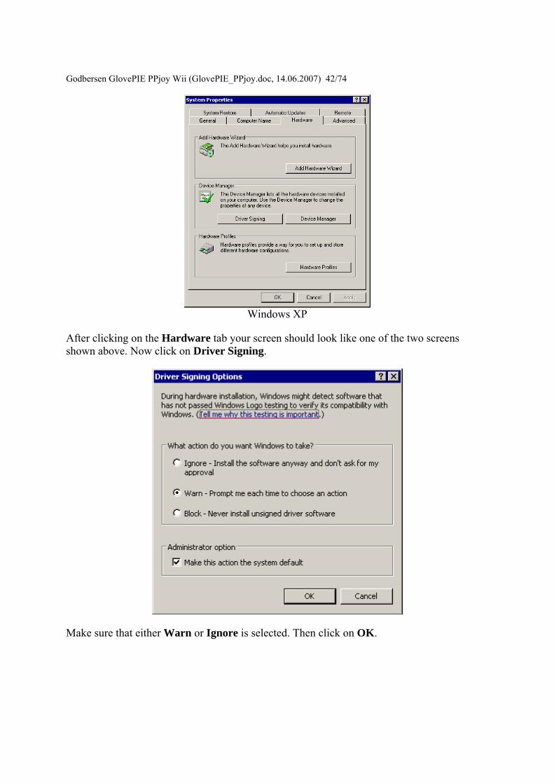
Godbersen GlovePIE PPjoy W
ii (GlovePIE_PPjoydoc 14062007) 4274
Windows XP
After clicking on the Hardware tab your screen should look like one of the two screens shown above Now click on Driver Signing
Make sure that either Warn or Ignore is selected Then click on OK
Godbersen GlovePIE PPjoy Wii (GlovePIE_PPjoydoc 14062007) 4374
Unsigned Driver warning messages Warning screens for Windows XP If you see a screen similar to this one during installation or while adding a new joystick please click on Continue Anyway
Error screens for Windows XP If you see a screen like this one during installation your computer is not allowing unsigned drivers to be installed Please cancel the installation and review the information in Changing the Driver Signing settings
Godbersen GlovePIE PPjoy Wii (GlovePIE_PPjoydoc 14062007) 4474
Opening the PPJoy Control Panel applet This document describes how to open the PPJoy Control Panel applet The PPJoy applet is used to add and remove joysticks that are plugged into the Parallel Port
First click Start on the Taskbar then Settings and finally on Control Panel This will open the Control Panel
In Control Panel double-click on the Parallel Port Joysticks icon (shown highlighted) This will open the PPJoy Control Panel applet
Godbersen Glov
ePIE PPjoy Wii (GlovePIE_PPjoydoc 14062007) 4574
This is the main PPJoy applet window From this screen you will add and remove joysticks that are connected to the Parallel Port Joysticks that connect to the Gameport or USB will not show up here
If you get this error message instead of the PPJoy applet you need to make sure that PPJoyBussys is installed
Under Windows 98Me you need to install it yourself (see Windows 98 Post-Install actions) Under Windows 2000XP you need to make sure your settings allow the installation of unsigned drivers (see Driver signing for more information) and re-install the software
Adding a new joystick or gamepad This document describes how to add a new joystick or gamepad to PPJoy using the Control Panel applet See Opening the Control Panel applet for information on how to open the PPJoy control Panel applet
Godbersen Glov
ePIE PPjoy Wii (GlovePIE_PPjoydoc 14062007) 4674
To add a new controller click on the Add button in the PPJoy applet A new dialog box similar to the one below should appear
Or you may get this error message
Godbersen GlovePIE PPjo
y Wii (GlovePIE_PPjoydoc 14062007) 4774
PPJoy only supports 16 joysticks (due to a Windows limitation) and will give this error message when you try to add the 17th Joystick
First select the Parallel Port to which the joystick interface will be connected Only the ports on which new joysticks can be created will be shown The Virtual port is a special port that allows other applications to send joystick input via PPJoy
If there is only one port available it will be automatically selected and the field will be greyed out
Godbersen GlovePIE PPjoy Wii (GlovePIE_PPjoydoc 14062007) 4874 Next select the type of controller that is you want to connect to the particular port The interfaces available (see below) will depend on the selection made here The following controller types are currently supported
bull Joystick Standard digital joystick like on Commodore 64 Amstrad Spectrum etc or any other device that does not fit into the categories below
bull Genesis pad This is for Sega GenesisMegadrive controllers bull SNES or NES pad Nintendo NES SNES or Virtual Gameboy controllers bull Playstation pad Playstation or Playstation 2 controllers bull Virtual joystick Joystick device emulated by a Win32 application (minidriver)
Only the Virtual joystick device will only be shown when the Virtual Port is selected as parallel port The other device types will be shown for normal parallel ports
You cannot have more than one controller type or interface type on a single port If there are already joysticks defined for a given port the Controller Type and Interface Type will automatically be selected and greyed out
Next select the interface type that will be connected to the port This field will be greyed out if there is already an interface type defined for the selected port The list of interfaces shown are dependent on the Controller Type selected above
Note that the Controller Type and Interface Type together determines which physical interface is used For example the DirectPad Pro interface for the Playstation Pad Controller Type is very different from the DirectPad Pro interface for the Joystick Controller type
Godbersen GlovePIE
PPjoy Wii (GlovePIE_PPjoydoc 14062007) 4974
If the selected interface allows more than joystick to be connected (eg TurboGraFX or Linux0802) this field will allow you to choose the specific joystick If the interface only caters for one joystick this field will be greyed out
The last field allows you to select the specific type of controller connected if applicable
Currently the SNES or NES pad and Genesis pad controller type require a sub type to be specified because the sub types are read in different ways
Sub types for SNES or NES pad
bull SNES or Virtual Gameboy bull NES
Sub types for Genesis pad
bull ABC and Start This is the earlier Genesis pad
Godbersen GlovePIE PPjoy Wii (GlovePIE_PPjoydoc 14062007) 5074
bull ABCXYZ Start and Mode This is the later Genesis pad with 6 buttons
Click on Add to add the joystick to the system The screenshots shown below are from Windows XP the sequence for Windows 2000 is very similar On Windows 98Me you will need your original CD as Windows 98Me needs to install a driver from the CD
Make sure that Install the software automatically (as shown) are selected and click on Next
Click on Continue Anyway (Windows XP) or Yes (Windows 2000) if a warning appears about unsigned drivers This will depend on your settings for driver signing
Godbersen GlovePIE PPjoy W
ii (GlovePIE_PPjoydoc 14062007) 5174
Click on Finish
Make sure that Install the software automatically (as shown) are selected and click on Next
Click on Finish
Godbersen GlovePIE PPjoy Wii (GlovePIE_PPjoydoc 14062007) 5274
Removing an existing joystick This document describes how to remove an existing joystick using the PPJoy Control Panel applet See Opening the Control Panel applet for information on how to open the PPJoy control Panel applet
To delete a joystick select a joystick from the list displayed in the PPJoy applet then click on Remove Remove will only be enabled after you have selected a joystick from the list
There are two options when deleting a joystick
Remove joystick config from DirectInput should normally be ticked If it is not ticked the rest of Windows will think the joystick is simply unplugged It may also lead to failure when adding additional joysticks
Remove joystick driver from the system determines whether to delete the PPJoy device driver for the specified joystick It can safely be unchecked PPJoy uses a pool of up to 16 device drivers for the joysticks it emulates and can reuse the driver of a deleted joystick
Click on OK to confirm the deletion
Godbersen GlovePIE PPjoy Wii (GlovePIE_PPjoydoc 14062007) 5374
Changing button and axis the mapping PPJoy allows you to completely change the way the joystick buttons and axes configured The following topics will explain the mapping process in more detail
bull Important concepts bull Changing the button and axis mapping of a joystick bull Deleting a joystick mapping
Important concepts There are three levels of mapping in PPJoy
bull The Default mapping is used when there is no more specific (interface or individual) mapping for a particular joystick
bull The Interface mapping mapping applies to all joysticks without individual mappings that connect to this interface type
bull Individual mappings apply to a single joystick
If an individual mapping is defined for a joystick it will always be used If a joystick has no individual mapping the interface mapping will be used instead If there is no individual or interface mapping for a joystick the built-in default mapping will be used
The joystick mapping is used to transform the raw digital and analog values that PPJoy reads from a joystick into button presses axis movements and POV direction
bull Controls with an on-off motion are read as digital values All the buttons and the axes on most of the supported joysticks fall into this category
bull Controls with a range of motion are read as analog values Currently the Playstation controllers FMS PPM RC and the virtual joystick can return analog values
A button press can be mapped in the following ways
bull As a digital value read from a joystick bull When an analog control is moved to its minimum position bull When an analog control is moved to its maximum position bull As nothing in which case the button will never be pressed
An axis can be mapped in the following ways
bull Directly as an analog value read from a joystick bull Reverse of the analog value read from a joystick bull Two digital values one for minimum and one for the maximum axis position bull As nothing in which case the axis will always be centred
A POV hat can be mapped in three ways
bull As four directions These directional input can be any combination of button presses or axis minmax movements
Godbersen GlovePIE PPjoy Wii (GlovePIE_PPjoydoc 14062007) 5474
bull As a continuous direction between 0 and 359 degrees In this case a single analog input is used
bull As nothing in which case the POV hat will report not pressed
PPJoy allows you change the number of buttons and axes and POV hats reported for a joystick By default only the virtual joystick and PSX controllers have a POV hat defined
Changing the button and axis mapping of a joystick
Start by selecting the joystick to change and click on the Mapping button A new dialog box similar to the one below should appear
Godbersen Gl
ovePIE PPjoy Wii (GlovePIE_PPjoydoc 14062007) 5574
Broadly there are two groups of options the interface (top three) and individual (bottom three) options If no mapping exists for a given category (interface or individual) you are offered the chance to create a mapping else you have to option to modify or delete the mapping See the section Deleting a mapping for more information on how to delete a joystick mapping
The interface mapping will affect all controllers using that interface type unless the controller has its own individual mapping Individual mappings will always take precedence over interface mappings
If you choose a Set (Create) or Modify option and click on Next you will see the screen below
Godbersen Gl
ovePIE PPjoy Wii (GlovePIE_PPjoydoc 14062007) 5674
This screen will show you the number of buttons axes and hats that PPJoy will report to Windows for this device It will also show you the HID types reported for the axes You can change the number of axes buttons and hats reported to DirectX as well as their types Older verions of DirectX does not like this and will cause DrWatson errors in the Game Controllers Control Panel and possibly other applications as well Changing these values with DirectX 9 installed on Windows XP seems to work fine
Click on Next to continue
Godbersen Gl
ovePIE PPjoy Wii (GlovePIE_PPjoydoc 14062007) 5774
This screen will allow you to change the mapping for each axis Note that playstation pads have two mapping modes - digital and analog mode After configuring the mapping for digital mode you will be shown the same screens to configure the mapping for analog mode Currently all other devices only have a single mapping mode
An axis can be mapped in one of the following ways
bull Directly as an analog value read from a joystick for example an analog Playstation pad (Analog xx in the drop-down list)
bull An analog value read from a joystick with the direction reversed (Analog xx rev in the drop-down list)
bull Two digital values (buttons or digital joystick axes) one for minimum and one for the maximum axis position (Digital xx in the drop-down list)
bull As nothing in which case the axis will always be centred (nothing in the drop-down list)
The easiest way to set the mapping for a particular axis is to click on the Scan button in the Min column next to the axis you want to change The following screen will appear
Godbersen GlovePIE PPjoy Wii (G
lovePIE_PPjoydoc 14062007) 5874
Now press the button or move the control in the minimum (up left) direction that you want to map to this axis As soon as PPJoy senses any button press or axis movement on the selected device it will close the scan dialog and update the mapping page (If a button is pressed or an axis moved before clicking on the scan button the mapping page will immediately be updated and the scan dialog will not appear)
When an analog value is selected in the Min column for an axis the Max column for that axis will be greyed out This is because a single analog value completely defines an axis When a digital value is entered in the axis minimum column another digital value must be specified in the maximum column for that axis
Most interfaces will report the following values for up down left and right
bull D 0 Joystick is pressed UP bull D 1 Joystick is pressed DOWN bull D 2 Joystick is pressed LEFT bull D 3 Joystick is pressed RIGHT
When all the axis mappings are configured click on Next This takes you to the button mapping page
Godbersen Gl
ovePIE PPjoy Wii (GlovePIE_PPjoydoc 14062007) 5974
The button mapping page operates similar to the axis mapping page A button can be mapped in the following ways
bull Directly as digital value read from a joystick (Digital xx in the drop-down list) bull An analog value set to its minimum value (position) (Analog xx min in the drop-
down list) bull An analog value set to its maximum value (position) (Analog xx max in the drop-
down list) bull As nothing in which case the button will never be pressed (nothing in the drop-down
list)
The scan button operates the same as it does on the axis mapping page
Click on Next when you configured all the buttons If the device has more than 16 buttons you will be shown the button mapping page again this time for buttons 17 to (possibly) 32 otherwise you will proceed to the POV hat mapping page If there is no POV hat defined for the device this page is skipped
Godbersen Gl
ovePIE PPjoy Wii (GlovePIE_PPjoydoc 14062007) 6074
If you select a directional button POV you must provide a mapping for 4 buttons The mapping for these direction buttons works exactly like the mapping of (fire) buttons on the previous page
For a continuous position POV you must provide an analog input for the POV - you cannot use any digital inputs here Just like for axes you can use the analog value in its normal and reversed senses Take note that very few devices provides analog inputs
If this device has more than one configuration (like playstation pads) the Next button will take you to the axis mapping page for the next mapping After you have finished configuring the POV hats for the last mapping mode you will be moved on to the finish screen
Godbersen GlovePIE PPjo
y Wii (GlovePIE_PPjoydoc 14062007) 6174
This screen confirms that the mapping is complete It is also your last chance to cancel without writing the mapping to the joystick driver Click on Finish to write the new mapping to the driver
Deleting a joystick mapping
Godbersen Gl
ovePIE PPjoy Wii (GlovePIE_PPjoydoc 14062007) 6274
Start by selecting a joystick and clicking on the Mapping button
Select whether you want to delete the individual mapping for a joystick or the interface mapping Then click on Next If a mapping does not exist the option to delete it will be greyed out
Godbersen Gl
ovePIE PPjoy Wii (GlovePIE_PPjoydoc 14062007) 6374
This is the confirmation screen before the delete You have to select Yes before the Finish button will be activated After you selected Yes click on Finish
Changing the joystick interface timing parameters Certain joystick interfaces require relatively long delays which uses a lot of CPU cycles to read the joystick PPJoy allows you to customise the timing values used in order to minimize the CPU usage
Below is a list of the joystick and gamepad interfaces that have configurable timing parameters
bull Genesis gamepads bull NESSNES gamepads bull Playstation controllers bull LPT-switch controller bull FMS PPM RC transmitter
The following topics will explain changing timing parameters in more detail
bull Important concepts bull Changing the joystick timing parameters bull Deleting timing parameters
Godbersen GlovePIE PPjoy Wii (GlovePIE_PPjoydoc 14062007) 6474 Important concepts There are three levels of timing parameters in PPJoy
bull The Default timing is used when there are no more specific (interface or individual) timing parameters for a particular joystick They are probably not optimal for your controller but should be adequate in most cases
bull The Interface timing applies to all joysticks without individual timings that connect to this interface type
bull Individual timing applies to a single joystick
If individual timing parameters are defined for a joystick they will always be used If a joystick has no individual timing parameters the interface timing will be used instead If there is no individual or interface timing for a joystick the built-in default timing parameters will be used
Different interfaces even for the same controller type have separate interface timing settings For example the DirectPad Pro and Linux interfaces for Playstation controllers will each have their own interface timing parameters
Changing the joystick timing parameters
Start by selecting the joystick to change and click on the Timing button A new dialog box similar to the one below should appear
Godbersen Gl
ovePIE PPjoy Wii (GlovePIE_PPjoydoc 14062007) 6574
Broadly there are two groups of options the interface (top three) and individual (bottom three) options If no timing parameters exist for a given category (interface or individual) you are offered the chance to create new timing parameters else you have to option to modify or delete them See the section Deleting timing parameters for more information on how to delete the timing parameters
The interface timing parameters will affect all controllers using that interface type unless the controller has its own individual parameters Individual timing parameters will always take precedence over interface parameters
If you choose a Set (Create) or Modify option and click on Next you will see a screen like the one below The exact screen will depend on the joystick type for which you want to modify the timing parameters
Godbersen Gl
ovePIE PPjoy Wii (GlovePIE_PPjoydoc 14062007) 6674
The top part of the screen will list the timing parameters available for the selected controller or interface and allow you to change them Click on Apply to activate the new parameters while keeping the wizard open Clicking on Finish will apply the new timing values and close the wizard
The best strategy to configure timing parameters is probably to gradually lower and apply one parameter until the controllers operation becomes unstable Repeat this process for the other parameters
Clicking on Reset defaults will change the timing parameters back to the values they were when the wizard was started and apply them
Click on Finish after modifying the timing parameters
Godbersen Glov
ePIE PPjoy Wii (GlovePIE_PPjoydoc 14062007) 6774
Deleting timing parameters
Start by selecting a joystick and clicking on the Timing button
Godbersen Gl
ovePIE PPjoy Wii (GlovePIE_PPjoydoc 14062007) 6874
Select whether you want to delete the individual timing parameters for a joystick or the interface timing parameters Then click on Next If timing parameters do not exist the option to delete it will be greyed out
Godbersen Gl
ovePIE PPjoy Wii (GlovePIE_PPjoydoc 14062007) 6974
This is the confirmation screen before the delete You have to select Yes before the Finish button will be activated After you selected Yes click on Finish
Introduction This page provides information on the timing parameters available to tune the way PPJoy scans various controller types
The following controller types have customisable timing parameters
bull Sega Genesis controllers bull LPT-switch controllers bull PPM RC transmitters bull Playstation controllers bull SNESNES controllers
Sega Genesis controller timing parameters The timing parameters presented below are applicable to all Genesys interfaces
Godb
ersen GlovePIE PPjoy Wii (GlovePIE_PPjoydoc 14062007) 7074
There are two protocols used to Sega Genesis controllers The protocol used depends on the controller subtype specified when the controller was added If you specify ABC and Start as the controller type the 3-button protocol will be used if you specify ABCXYZ Start and Mode the 6-button protocol is used
bull Genesis interbit delay specifies the number of microseconds delay between changing the state of the Select line and reading the joystick state when using the 3-button protocol
bull Genesis 6 button interbit delay specifies the number of microseconds delay between changing the state of the Select line and reading the joystick state when using the 6-button protocol
LPT-switch controller timing parameters The timing parameters presented below are applicable to the LPT-switch interface
Godbersen Glov
ePIE PPjoy Wii (GlovePIE_PPjoydoc 14062007) 7174
The LPTswitch interface has a single timing parameter LPTswitch row select delay This parameter specifies the delay in microseconds between setting the row-select line low and reading the column data from the interface
PPM RC transmitter timing parameters The timing parameters presented below are applicable to the PPM RC transmitter interface
The PPM RC IRQ interface measures the durations between two consecutive low-to-high transitions of the IRQ pin This means that PPJoy does not care whether the timing pulses are high or low (Normal or Inverted signal)
The three applicable timing parameters are
bull PPM min servo pulse width specifies the minimum duration in microseconds between timing pulses If the duration between two consecutive pulses is less than this value the corresponding joystick axis will report its minimum position
bull PPM max servo pulse width specifies the maximum duration in microseconds between timing pulses If the duration between two consecutive pulses is more than this value but less than the minimum sync pulse width the corresponding joystick axis will report its maximum position
Godbersen GlovePIE PPjoy Wii (GlovePIE_PPjoydoc 14062007) 7274
bull PPM min sync pulse width specifies the minimum duration in microseconds of the sync pulse An inter-pulse duration greater than this value marks the beginning of a new frame
Playstation timing parameters The timing parameters presented below are applicable to Playstation interfaces
The figure above is timing for the transfer of an entire data packet The diagram below details the transfer of a single byte between the PC and PSX controller
There are five parameters for Playstation controllers
bull PSX Sel delay specifies the duration in microseconds that the select signal will be taken low before the first byte is transferred
bull PSX Bit delay specifies the duration in microseconds the delay between setting the clock signal high and writing a bit to the controller and between setting the clock line low and reading a bit from the controller
bull PSX Ack1 delay specifies the maximum duration in microseconds to wait for an ACK pulse from the controller after transferring the first byte to the controller
bull PSX AckX delay specifies the maximum duration in microseconds to wait for an ACK pulse from the controller after transferring the second or later byte to the controller
bull PSX Tail delay specifies the duration in microseconds that the Select signal will remain low after the packet transfer between the PC and controller is completed
Godb
ersen GlovePIE PPjoy Wii (GlovePIE_PPjoydoc 14062007) 7374
SNESNES timing parameters The timing parameters presented below are applicable to all SNESNESVirtual Gameboy interfaces
SNESNES interfaces have two timing parameters
bull SNES setup delay specifies the duration in microseconds that the latch signal will be held high
bull SNES interbit delay specifies the duration in microseconds between changes in the signal Every two bit delays an input bit will be read from the controller
Setting PPJoy global options PPJoy has a number of global options that affects the operation of one or more interfaces The options screen shown below can be activated by clicking on the Options button in the main PPJoy screen
Currently PPJoy supports the following options
bull Debug PPM RC interface Setting this option causes PPJoy to make a click (toggle speaker state) every time it detects an incoming pulse from PPM interface (LPT IRQ triggered) When the interface is working properly you should hear a steady tone
Godbersen GlovePIE PPjoy Wii (GlovePIE_PPjoydoc 14062007) 7474
bull Debug Playstation interfaces Setting this option causes PPJoy to make a click each time it reads an invalidcorrupted data packet from a playstation controller
bull Dont allocate ports to assigned joysticks This option only affects PPJoy on Windows 2000 XP and 2003 When it is set PPJoy acts the same way is does on Windows 98 Me where it does not allocate a parallel port when a joystick is configured Thus you do not have to disable PPJoy to use a printer connected to the parallel port
It is recommended that you do not turn on this option Turning on this option may interfere with printing and will also disable the PPM RC interface You need to restart your computer for changes to this option to take effect
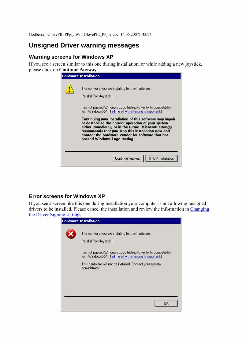
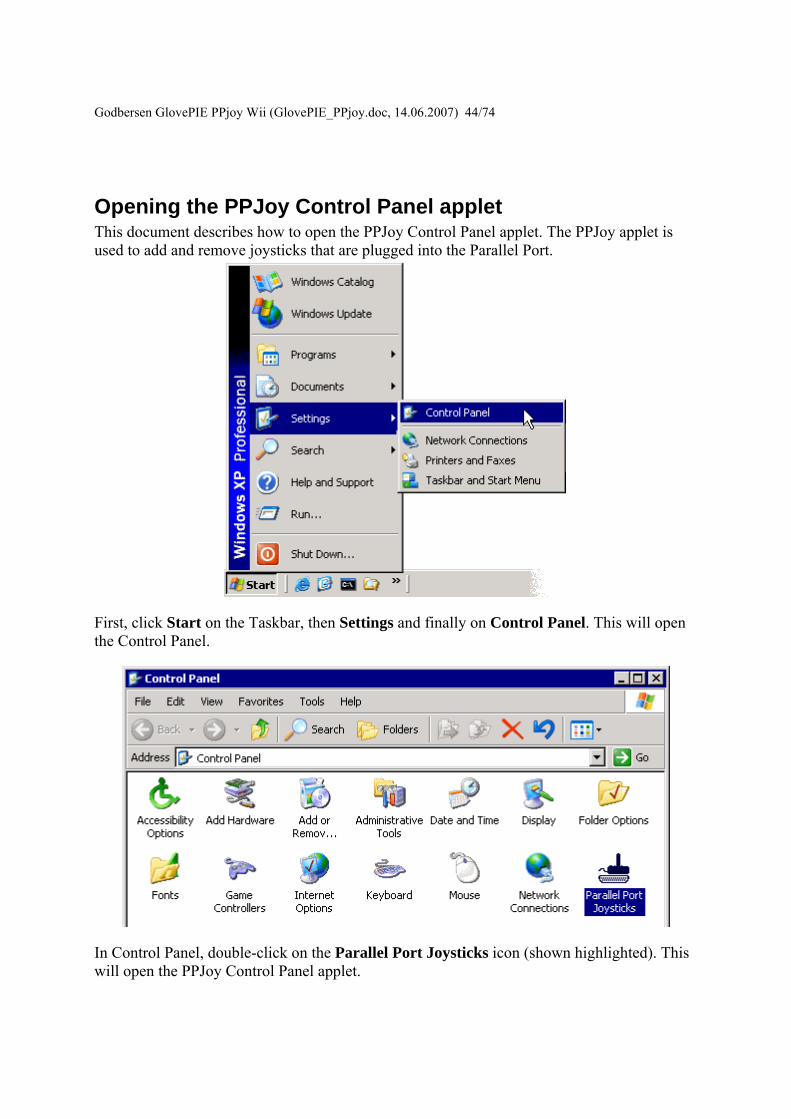
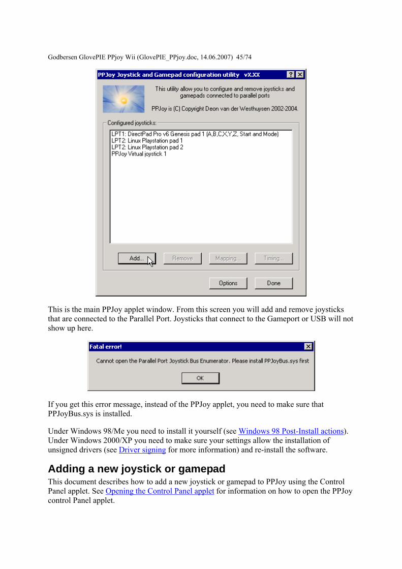
Godbersen Glov
ePIE PPjoy Wii (GlovePIE_PPjoydoc 14062007) 4574
This is the main PPJoy applet window From this screen you will add and remove joysticks that are connected to the Parallel Port Joysticks that connect to the Gameport or USB will not show up here
If you get this error message instead of the PPJoy applet you need to make sure that PPJoyBussys is installed
Under Windows 98Me you need to install it yourself (see Windows 98 Post-Install actions) Under Windows 2000XP you need to make sure your settings allow the installation of unsigned drivers (see Driver signing for more information) and re-install the software
Adding a new joystick or gamepad This document describes how to add a new joystick or gamepad to PPJoy using the Control Panel applet See Opening the Control Panel applet for information on how to open the PPJoy control Panel applet
Godbersen Glov
ePIE PPjoy Wii (GlovePIE_PPjoydoc 14062007) 4674
To add a new controller click on the Add button in the PPJoy applet A new dialog box similar to the one below should appear
Or you may get this error message
Godbersen GlovePIE PPjo
y Wii (GlovePIE_PPjoydoc 14062007) 4774
PPJoy only supports 16 joysticks (due to a Windows limitation) and will give this error message when you try to add the 17th Joystick
First select the Parallel Port to which the joystick interface will be connected Only the ports on which new joysticks can be created will be shown The Virtual port is a special port that allows other applications to send joystick input via PPJoy
If there is only one port available it will be automatically selected and the field will be greyed out
Godbersen GlovePIE PPjoy Wii (GlovePIE_PPjoydoc 14062007) 4874 Next select the type of controller that is you want to connect to the particular port The interfaces available (see below) will depend on the selection made here The following controller types are currently supported
bull Joystick Standard digital joystick like on Commodore 64 Amstrad Spectrum etc or any other device that does not fit into the categories below
bull Genesis pad This is for Sega GenesisMegadrive controllers bull SNES or NES pad Nintendo NES SNES or Virtual Gameboy controllers bull Playstation pad Playstation or Playstation 2 controllers bull Virtual joystick Joystick device emulated by a Win32 application (minidriver)
Only the Virtual joystick device will only be shown when the Virtual Port is selected as parallel port The other device types will be shown for normal parallel ports
You cannot have more than one controller type or interface type on a single port If there are already joysticks defined for a given port the Controller Type and Interface Type will automatically be selected and greyed out
Next select the interface type that will be connected to the port This field will be greyed out if there is already an interface type defined for the selected port The list of interfaces shown are dependent on the Controller Type selected above
Note that the Controller Type and Interface Type together determines which physical interface is used For example the DirectPad Pro interface for the Playstation Pad Controller Type is very different from the DirectPad Pro interface for the Joystick Controller type
Godbersen GlovePIE
PPjoy Wii (GlovePIE_PPjoydoc 14062007) 4974
If the selected interface allows more than joystick to be connected (eg TurboGraFX or Linux0802) this field will allow you to choose the specific joystick If the interface only caters for one joystick this field will be greyed out
The last field allows you to select the specific type of controller connected if applicable
Currently the SNES or NES pad and Genesis pad controller type require a sub type to be specified because the sub types are read in different ways
Sub types for SNES or NES pad
bull SNES or Virtual Gameboy bull NES
Sub types for Genesis pad
bull ABC and Start This is the earlier Genesis pad
Godbersen GlovePIE PPjoy Wii (GlovePIE_PPjoydoc 14062007) 5074
bull ABCXYZ Start and Mode This is the later Genesis pad with 6 buttons
Click on Add to add the joystick to the system The screenshots shown below are from Windows XP the sequence for Windows 2000 is very similar On Windows 98Me you will need your original CD as Windows 98Me needs to install a driver from the CD
Make sure that Install the software automatically (as shown) are selected and click on Next
Click on Continue Anyway (Windows XP) or Yes (Windows 2000) if a warning appears about unsigned drivers This will depend on your settings for driver signing
Godbersen GlovePIE PPjoy W
ii (GlovePIE_PPjoydoc 14062007) 5174
Click on Finish
Make sure that Install the software automatically (as shown) are selected and click on Next
Click on Finish
Godbersen GlovePIE PPjoy Wii (GlovePIE_PPjoydoc 14062007) 5274
Removing an existing joystick This document describes how to remove an existing joystick using the PPJoy Control Panel applet See Opening the Control Panel applet for information on how to open the PPJoy control Panel applet
To delete a joystick select a joystick from the list displayed in the PPJoy applet then click on Remove Remove will only be enabled after you have selected a joystick from the list
There are two options when deleting a joystick
Remove joystick config from DirectInput should normally be ticked If it is not ticked the rest of Windows will think the joystick is simply unplugged It may also lead to failure when adding additional joysticks
Remove joystick driver from the system determines whether to delete the PPJoy device driver for the specified joystick It can safely be unchecked PPJoy uses a pool of up to 16 device drivers for the joysticks it emulates and can reuse the driver of a deleted joystick
Click on OK to confirm the deletion
Godbersen GlovePIE PPjoy Wii (GlovePIE_PPjoydoc 14062007) 5374
Changing button and axis the mapping PPJoy allows you to completely change the way the joystick buttons and axes configured The following topics will explain the mapping process in more detail
bull Important concepts bull Changing the button and axis mapping of a joystick bull Deleting a joystick mapping
Important concepts There are three levels of mapping in PPJoy
bull The Default mapping is used when there is no more specific (interface or individual) mapping for a particular joystick
bull The Interface mapping mapping applies to all joysticks without individual mappings that connect to this interface type
bull Individual mappings apply to a single joystick
If an individual mapping is defined for a joystick it will always be used If a joystick has no individual mapping the interface mapping will be used instead If there is no individual or interface mapping for a joystick the built-in default mapping will be used
The joystick mapping is used to transform the raw digital and analog values that PPJoy reads from a joystick into button presses axis movements and POV direction
bull Controls with an on-off motion are read as digital values All the buttons and the axes on most of the supported joysticks fall into this category
bull Controls with a range of motion are read as analog values Currently the Playstation controllers FMS PPM RC and the virtual joystick can return analog values
A button press can be mapped in the following ways
bull As a digital value read from a joystick bull When an analog control is moved to its minimum position bull When an analog control is moved to its maximum position bull As nothing in which case the button will never be pressed
An axis can be mapped in the following ways
bull Directly as an analog value read from a joystick bull Reverse of the analog value read from a joystick bull Two digital values one for minimum and one for the maximum axis position bull As nothing in which case the axis will always be centred
A POV hat can be mapped in three ways
bull As four directions These directional input can be any combination of button presses or axis minmax movements
Godbersen GlovePIE PPjoy Wii (GlovePIE_PPjoydoc 14062007) 5474
bull As a continuous direction between 0 and 359 degrees In this case a single analog input is used
bull As nothing in which case the POV hat will report not pressed
PPJoy allows you change the number of buttons and axes and POV hats reported for a joystick By default only the virtual joystick and PSX controllers have a POV hat defined
Changing the button and axis mapping of a joystick
Start by selecting the joystick to change and click on the Mapping button A new dialog box similar to the one below should appear
Godbersen Gl
ovePIE PPjoy Wii (GlovePIE_PPjoydoc 14062007) 5574
Broadly there are two groups of options the interface (top three) and individual (bottom three) options If no mapping exists for a given category (interface or individual) you are offered the chance to create a mapping else you have to option to modify or delete the mapping See the section Deleting a mapping for more information on how to delete a joystick mapping
The interface mapping will affect all controllers using that interface type unless the controller has its own individual mapping Individual mappings will always take precedence over interface mappings
If you choose a Set (Create) or Modify option and click on Next you will see the screen below
Godbersen Gl
ovePIE PPjoy Wii (GlovePIE_PPjoydoc 14062007) 5674
This screen will show you the number of buttons axes and hats that PPJoy will report to Windows for this device It will also show you the HID types reported for the axes You can change the number of axes buttons and hats reported to DirectX as well as their types Older verions of DirectX does not like this and will cause DrWatson errors in the Game Controllers Control Panel and possibly other applications as well Changing these values with DirectX 9 installed on Windows XP seems to work fine
Click on Next to continue
Godbersen Gl
ovePIE PPjoy Wii (GlovePIE_PPjoydoc 14062007) 5774
This screen will allow you to change the mapping for each axis Note that playstation pads have two mapping modes - digital and analog mode After configuring the mapping for digital mode you will be shown the same screens to configure the mapping for analog mode Currently all other devices only have a single mapping mode
An axis can be mapped in one of the following ways
bull Directly as an analog value read from a joystick for example an analog Playstation pad (Analog xx in the drop-down list)
bull An analog value read from a joystick with the direction reversed (Analog xx rev in the drop-down list)
bull Two digital values (buttons or digital joystick axes) one for minimum and one for the maximum axis position (Digital xx in the drop-down list)
bull As nothing in which case the axis will always be centred (nothing in the drop-down list)
The easiest way to set the mapping for a particular axis is to click on the Scan button in the Min column next to the axis you want to change The following screen will appear
Godbersen GlovePIE PPjoy Wii (G
lovePIE_PPjoydoc 14062007) 5874
Now press the button or move the control in the minimum (up left) direction that you want to map to this axis As soon as PPJoy senses any button press or axis movement on the selected device it will close the scan dialog and update the mapping page (If a button is pressed or an axis moved before clicking on the scan button the mapping page will immediately be updated and the scan dialog will not appear)
When an analog value is selected in the Min column for an axis the Max column for that axis will be greyed out This is because a single analog value completely defines an axis When a digital value is entered in the axis minimum column another digital value must be specified in the maximum column for that axis
Most interfaces will report the following values for up down left and right
bull D 0 Joystick is pressed UP bull D 1 Joystick is pressed DOWN bull D 2 Joystick is pressed LEFT bull D 3 Joystick is pressed RIGHT
When all the axis mappings are configured click on Next This takes you to the button mapping page
Godbersen Gl
ovePIE PPjoy Wii (GlovePIE_PPjoydoc 14062007) 5974
The button mapping page operates similar to the axis mapping page A button can be mapped in the following ways
bull Directly as digital value read from a joystick (Digital xx in the drop-down list) bull An analog value set to its minimum value (position) (Analog xx min in the drop-
down list) bull An analog value set to its maximum value (position) (Analog xx max in the drop-
down list) bull As nothing in which case the button will never be pressed (nothing in the drop-down
list)
The scan button operates the same as it does on the axis mapping page
Click on Next when you configured all the buttons If the device has more than 16 buttons you will be shown the button mapping page again this time for buttons 17 to (possibly) 32 otherwise you will proceed to the POV hat mapping page If there is no POV hat defined for the device this page is skipped
Godbersen Gl
ovePIE PPjoy Wii (GlovePIE_PPjoydoc 14062007) 6074
If you select a directional button POV you must provide a mapping for 4 buttons The mapping for these direction buttons works exactly like the mapping of (fire) buttons on the previous page
For a continuous position POV you must provide an analog input for the POV - you cannot use any digital inputs here Just like for axes you can use the analog value in its normal and reversed senses Take note that very few devices provides analog inputs
If this device has more than one configuration (like playstation pads) the Next button will take you to the axis mapping page for the next mapping After you have finished configuring the POV hats for the last mapping mode you will be moved on to the finish screen
Godbersen GlovePIE PPjo
y Wii (GlovePIE_PPjoydoc 14062007) 6174
This screen confirms that the mapping is complete It is also your last chance to cancel without writing the mapping to the joystick driver Click on Finish to write the new mapping to the driver
Deleting a joystick mapping
Godbersen Gl
ovePIE PPjoy Wii (GlovePIE_PPjoydoc 14062007) 6274
Start by selecting a joystick and clicking on the Mapping button
Select whether you want to delete the individual mapping for a joystick or the interface mapping Then click on Next If a mapping does not exist the option to delete it will be greyed out
Godbersen Gl
ovePIE PPjoy Wii (GlovePIE_PPjoydoc 14062007) 6374
This is the confirmation screen before the delete You have to select Yes before the Finish button will be activated After you selected Yes click on Finish
Changing the joystick interface timing parameters Certain joystick interfaces require relatively long delays which uses a lot of CPU cycles to read the joystick PPJoy allows you to customise the timing values used in order to minimize the CPU usage
Below is a list of the joystick and gamepad interfaces that have configurable timing parameters
bull Genesis gamepads bull NESSNES gamepads bull Playstation controllers bull LPT-switch controller bull FMS PPM RC transmitter
The following topics will explain changing timing parameters in more detail
bull Important concepts bull Changing the joystick timing parameters bull Deleting timing parameters
Godbersen GlovePIE PPjoy Wii (GlovePIE_PPjoydoc 14062007) 6474 Important concepts There are three levels of timing parameters in PPJoy
bull The Default timing is used when there are no more specific (interface or individual) timing parameters for a particular joystick They are probably not optimal for your controller but should be adequate in most cases
bull The Interface timing applies to all joysticks without individual timings that connect to this interface type
bull Individual timing applies to a single joystick
If individual timing parameters are defined for a joystick they will always be used If a joystick has no individual timing parameters the interface timing will be used instead If there is no individual or interface timing for a joystick the built-in default timing parameters will be used
Different interfaces even for the same controller type have separate interface timing settings For example the DirectPad Pro and Linux interfaces for Playstation controllers will each have their own interface timing parameters
Changing the joystick timing parameters
Start by selecting the joystick to change and click on the Timing button A new dialog box similar to the one below should appear
Godbersen Gl
ovePIE PPjoy Wii (GlovePIE_PPjoydoc 14062007) 6574
Broadly there are two groups of options the interface (top three) and individual (bottom three) options If no timing parameters exist for a given category (interface or individual) you are offered the chance to create new timing parameters else you have to option to modify or delete them See the section Deleting timing parameters for more information on how to delete the timing parameters
The interface timing parameters will affect all controllers using that interface type unless the controller has its own individual parameters Individual timing parameters will always take precedence over interface parameters
If you choose a Set (Create) or Modify option and click on Next you will see a screen like the one below The exact screen will depend on the joystick type for which you want to modify the timing parameters
Godbersen Gl
ovePIE PPjoy Wii (GlovePIE_PPjoydoc 14062007) 6674
The top part of the screen will list the timing parameters available for the selected controller or interface and allow you to change them Click on Apply to activate the new parameters while keeping the wizard open Clicking on Finish will apply the new timing values and close the wizard
The best strategy to configure timing parameters is probably to gradually lower and apply one parameter until the controllers operation becomes unstable Repeat this process for the other parameters
Clicking on Reset defaults will change the timing parameters back to the values they were when the wizard was started and apply them
Click on Finish after modifying the timing parameters
Godbersen Glov
ePIE PPjoy Wii (GlovePIE_PPjoydoc 14062007) 6774
Deleting timing parameters
Start by selecting a joystick and clicking on the Timing button
Godbersen Gl
ovePIE PPjoy Wii (GlovePIE_PPjoydoc 14062007) 6874
Select whether you want to delete the individual timing parameters for a joystick or the interface timing parameters Then click on Next If timing parameters do not exist the option to delete it will be greyed out
Godbersen Gl
ovePIE PPjoy Wii (GlovePIE_PPjoydoc 14062007) 6974
This is the confirmation screen before the delete You have to select Yes before the Finish button will be activated After you selected Yes click on Finish
Introduction This page provides information on the timing parameters available to tune the way PPJoy scans various controller types
The following controller types have customisable timing parameters
bull Sega Genesis controllers bull LPT-switch controllers bull PPM RC transmitters bull Playstation controllers bull SNESNES controllers
Sega Genesis controller timing parameters The timing parameters presented below are applicable to all Genesys interfaces
Godb
ersen GlovePIE PPjoy Wii (GlovePIE_PPjoydoc 14062007) 7074
There are two protocols used to Sega Genesis controllers The protocol used depends on the controller subtype specified when the controller was added If you specify ABC and Start as the controller type the 3-button protocol will be used if you specify ABCXYZ Start and Mode the 6-button protocol is used
bull Genesis interbit delay specifies the number of microseconds delay between changing the state of the Select line and reading the joystick state when using the 3-button protocol
bull Genesis 6 button interbit delay specifies the number of microseconds delay between changing the state of the Select line and reading the joystick state when using the 6-button protocol
LPT-switch controller timing parameters The timing parameters presented below are applicable to the LPT-switch interface
Godbersen Glov
ePIE PPjoy Wii (GlovePIE_PPjoydoc 14062007) 7174
The LPTswitch interface has a single timing parameter LPTswitch row select delay This parameter specifies the delay in microseconds between setting the row-select line low and reading the column data from the interface
PPM RC transmitter timing parameters The timing parameters presented below are applicable to the PPM RC transmitter interface
The PPM RC IRQ interface measures the durations between two consecutive low-to-high transitions of the IRQ pin This means that PPJoy does not care whether the timing pulses are high or low (Normal or Inverted signal)
The three applicable timing parameters are
bull PPM min servo pulse width specifies the minimum duration in microseconds between timing pulses If the duration between two consecutive pulses is less than this value the corresponding joystick axis will report its minimum position
bull PPM max servo pulse width specifies the maximum duration in microseconds between timing pulses If the duration between two consecutive pulses is more than this value but less than the minimum sync pulse width the corresponding joystick axis will report its maximum position
Godbersen GlovePIE PPjoy Wii (GlovePIE_PPjoydoc 14062007) 7274
bull PPM min sync pulse width specifies the minimum duration in microseconds of the sync pulse An inter-pulse duration greater than this value marks the beginning of a new frame
Playstation timing parameters The timing parameters presented below are applicable to Playstation interfaces
The figure above is timing for the transfer of an entire data packet The diagram below details the transfer of a single byte between the PC and PSX controller
There are five parameters for Playstation controllers
bull PSX Sel delay specifies the duration in microseconds that the select signal will be taken low before the first byte is transferred
bull PSX Bit delay specifies the duration in microseconds the delay between setting the clock signal high and writing a bit to the controller and between setting the clock line low and reading a bit from the controller
bull PSX Ack1 delay specifies the maximum duration in microseconds to wait for an ACK pulse from the controller after transferring the first byte to the controller
bull PSX AckX delay specifies the maximum duration in microseconds to wait for an ACK pulse from the controller after transferring the second or later byte to the controller
bull PSX Tail delay specifies the duration in microseconds that the Select signal will remain low after the packet transfer between the PC and controller is completed
Godb
ersen GlovePIE PPjoy Wii (GlovePIE_PPjoydoc 14062007) 7374
SNESNES timing parameters The timing parameters presented below are applicable to all SNESNESVirtual Gameboy interfaces
SNESNES interfaces have two timing parameters
bull SNES setup delay specifies the duration in microseconds that the latch signal will be held high
bull SNES interbit delay specifies the duration in microseconds between changes in the signal Every two bit delays an input bit will be read from the controller
Setting PPJoy global options PPJoy has a number of global options that affects the operation of one or more interfaces The options screen shown below can be activated by clicking on the Options button in the main PPJoy screen
Currently PPJoy supports the following options
bull Debug PPM RC interface Setting this option causes PPJoy to make a click (toggle speaker state) every time it detects an incoming pulse from PPM interface (LPT IRQ triggered) When the interface is working properly you should hear a steady tone
Godbersen GlovePIE PPjoy Wii (GlovePIE_PPjoydoc 14062007) 7474
bull Debug Playstation interfaces Setting this option causes PPJoy to make a click each time it reads an invalidcorrupted data packet from a playstation controller
bull Dont allocate ports to assigned joysticks This option only affects PPJoy on Windows 2000 XP and 2003 When it is set PPJoy acts the same way is does on Windows 98 Me where it does not allocate a parallel port when a joystick is configured Thus you do not have to disable PPJoy to use a printer connected to the parallel port
It is recommended that you do not turn on this option Turning on this option may interfere with printing and will also disable the PPM RC interface You need to restart your computer for changes to this option to take effect
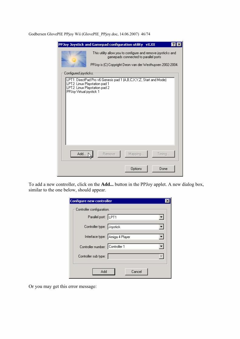
Godbersen Glov
ePIE PPjoy Wii (GlovePIE_PPjoydoc 14062007) 4674
To add a new controller click on the Add button in the PPJoy applet A new dialog box similar to the one below should appear
Or you may get this error message
Godbersen GlovePIE PPjo
y Wii (GlovePIE_PPjoydoc 14062007) 4774
PPJoy only supports 16 joysticks (due to a Windows limitation) and will give this error message when you try to add the 17th Joystick
First select the Parallel Port to which the joystick interface will be connected Only the ports on which new joysticks can be created will be shown The Virtual port is a special port that allows other applications to send joystick input via PPJoy
If there is only one port available it will be automatically selected and the field will be greyed out
Godbersen GlovePIE PPjoy Wii (GlovePIE_PPjoydoc 14062007) 4874 Next select the type of controller that is you want to connect to the particular port The interfaces available (see below) will depend on the selection made here The following controller types are currently supported
bull Joystick Standard digital joystick like on Commodore 64 Amstrad Spectrum etc or any other device that does not fit into the categories below
bull Genesis pad This is for Sega GenesisMegadrive controllers bull SNES or NES pad Nintendo NES SNES or Virtual Gameboy controllers bull Playstation pad Playstation or Playstation 2 controllers bull Virtual joystick Joystick device emulated by a Win32 application (minidriver)
Only the Virtual joystick device will only be shown when the Virtual Port is selected as parallel port The other device types will be shown for normal parallel ports
You cannot have more than one controller type or interface type on a single port If there are already joysticks defined for a given port the Controller Type and Interface Type will automatically be selected and greyed out
Next select the interface type that will be connected to the port This field will be greyed out if there is already an interface type defined for the selected port The list of interfaces shown are dependent on the Controller Type selected above
Note that the Controller Type and Interface Type together determines which physical interface is used For example the DirectPad Pro interface for the Playstation Pad Controller Type is very different from the DirectPad Pro interface for the Joystick Controller type
Godbersen GlovePIE
PPjoy Wii (GlovePIE_PPjoydoc 14062007) 4974
If the selected interface allows more than joystick to be connected (eg TurboGraFX or Linux0802) this field will allow you to choose the specific joystick If the interface only caters for one joystick this field will be greyed out
The last field allows you to select the specific type of controller connected if applicable
Currently the SNES or NES pad and Genesis pad controller type require a sub type to be specified because the sub types are read in different ways
Sub types for SNES or NES pad
bull SNES or Virtual Gameboy bull NES
Sub types for Genesis pad
bull ABC and Start This is the earlier Genesis pad
Godbersen GlovePIE PPjoy Wii (GlovePIE_PPjoydoc 14062007) 5074
bull ABCXYZ Start and Mode This is the later Genesis pad with 6 buttons
Click on Add to add the joystick to the system The screenshots shown below are from Windows XP the sequence for Windows 2000 is very similar On Windows 98Me you will need your original CD as Windows 98Me needs to install a driver from the CD
Make sure that Install the software automatically (as shown) are selected and click on Next
Click on Continue Anyway (Windows XP) or Yes (Windows 2000) if a warning appears about unsigned drivers This will depend on your settings for driver signing
Godbersen GlovePIE PPjoy W
ii (GlovePIE_PPjoydoc 14062007) 5174
Click on Finish
Make sure that Install the software automatically (as shown) are selected and click on Next
Click on Finish
Godbersen GlovePIE PPjoy Wii (GlovePIE_PPjoydoc 14062007) 5274
Removing an existing joystick This document describes how to remove an existing joystick using the PPJoy Control Panel applet See Opening the Control Panel applet for information on how to open the PPJoy control Panel applet
To delete a joystick select a joystick from the list displayed in the PPJoy applet then click on Remove Remove will only be enabled after you have selected a joystick from the list
There are two options when deleting a joystick
Remove joystick config from DirectInput should normally be ticked If it is not ticked the rest of Windows will think the joystick is simply unplugged It may also lead to failure when adding additional joysticks
Remove joystick driver from the system determines whether to delete the PPJoy device driver for the specified joystick It can safely be unchecked PPJoy uses a pool of up to 16 device drivers for the joysticks it emulates and can reuse the driver of a deleted joystick
Click on OK to confirm the deletion
Godbersen GlovePIE PPjoy Wii (GlovePIE_PPjoydoc 14062007) 5374
Changing button and axis the mapping PPJoy allows you to completely change the way the joystick buttons and axes configured The following topics will explain the mapping process in more detail
bull Important concepts bull Changing the button and axis mapping of a joystick bull Deleting a joystick mapping
Important concepts There are three levels of mapping in PPJoy
bull The Default mapping is used when there is no more specific (interface or individual) mapping for a particular joystick
bull The Interface mapping mapping applies to all joysticks without individual mappings that connect to this interface type
bull Individual mappings apply to a single joystick
If an individual mapping is defined for a joystick it will always be used If a joystick has no individual mapping the interface mapping will be used instead If there is no individual or interface mapping for a joystick the built-in default mapping will be used
The joystick mapping is used to transform the raw digital and analog values that PPJoy reads from a joystick into button presses axis movements and POV direction
bull Controls with an on-off motion are read as digital values All the buttons and the axes on most of the supported joysticks fall into this category
bull Controls with a range of motion are read as analog values Currently the Playstation controllers FMS PPM RC and the virtual joystick can return analog values
A button press can be mapped in the following ways
bull As a digital value read from a joystick bull When an analog control is moved to its minimum position bull When an analog control is moved to its maximum position bull As nothing in which case the button will never be pressed
An axis can be mapped in the following ways
bull Directly as an analog value read from a joystick bull Reverse of the analog value read from a joystick bull Two digital values one for minimum and one for the maximum axis position bull As nothing in which case the axis will always be centred
A POV hat can be mapped in three ways
bull As four directions These directional input can be any combination of button presses or axis minmax movements
Godbersen GlovePIE PPjoy Wii (GlovePIE_PPjoydoc 14062007) 5474
bull As a continuous direction between 0 and 359 degrees In this case a single analog input is used
bull As nothing in which case the POV hat will report not pressed
PPJoy allows you change the number of buttons and axes and POV hats reported for a joystick By default only the virtual joystick and PSX controllers have a POV hat defined
Changing the button and axis mapping of a joystick
Start by selecting the joystick to change and click on the Mapping button A new dialog box similar to the one below should appear
Godbersen Gl
ovePIE PPjoy Wii (GlovePIE_PPjoydoc 14062007) 5574
Broadly there are two groups of options the interface (top three) and individual (bottom three) options If no mapping exists for a given category (interface or individual) you are offered the chance to create a mapping else you have to option to modify or delete the mapping See the section Deleting a mapping for more information on how to delete a joystick mapping
The interface mapping will affect all controllers using that interface type unless the controller has its own individual mapping Individual mappings will always take precedence over interface mappings
If you choose a Set (Create) or Modify option and click on Next you will see the screen below
Godbersen Gl
ovePIE PPjoy Wii (GlovePIE_PPjoydoc 14062007) 5674
This screen will show you the number of buttons axes and hats that PPJoy will report to Windows for this device It will also show you the HID types reported for the axes You can change the number of axes buttons and hats reported to DirectX as well as their types Older verions of DirectX does not like this and will cause DrWatson errors in the Game Controllers Control Panel and possibly other applications as well Changing these values with DirectX 9 installed on Windows XP seems to work fine
Click on Next to continue
Godbersen Gl
ovePIE PPjoy Wii (GlovePIE_PPjoydoc 14062007) 5774
This screen will allow you to change the mapping for each axis Note that playstation pads have two mapping modes - digital and analog mode After configuring the mapping for digital mode you will be shown the same screens to configure the mapping for analog mode Currently all other devices only have a single mapping mode
An axis can be mapped in one of the following ways
bull Directly as an analog value read from a joystick for example an analog Playstation pad (Analog xx in the drop-down list)
bull An analog value read from a joystick with the direction reversed (Analog xx rev in the drop-down list)
bull Two digital values (buttons or digital joystick axes) one for minimum and one for the maximum axis position (Digital xx in the drop-down list)
bull As nothing in which case the axis will always be centred (nothing in the drop-down list)
The easiest way to set the mapping for a particular axis is to click on the Scan button in the Min column next to the axis you want to change The following screen will appear
Godbersen GlovePIE PPjoy Wii (G
lovePIE_PPjoydoc 14062007) 5874
Now press the button or move the control in the minimum (up left) direction that you want to map to this axis As soon as PPJoy senses any button press or axis movement on the selected device it will close the scan dialog and update the mapping page (If a button is pressed or an axis moved before clicking on the scan button the mapping page will immediately be updated and the scan dialog will not appear)
When an analog value is selected in the Min column for an axis the Max column for that axis will be greyed out This is because a single analog value completely defines an axis When a digital value is entered in the axis minimum column another digital value must be specified in the maximum column for that axis
Most interfaces will report the following values for up down left and right
bull D 0 Joystick is pressed UP bull D 1 Joystick is pressed DOWN bull D 2 Joystick is pressed LEFT bull D 3 Joystick is pressed RIGHT
When all the axis mappings are configured click on Next This takes you to the button mapping page
Godbersen Gl
ovePIE PPjoy Wii (GlovePIE_PPjoydoc 14062007) 5974
The button mapping page operates similar to the axis mapping page A button can be mapped in the following ways
bull Directly as digital value read from a joystick (Digital xx in the drop-down list) bull An analog value set to its minimum value (position) (Analog xx min in the drop-
down list) bull An analog value set to its maximum value (position) (Analog xx max in the drop-
down list) bull As nothing in which case the button will never be pressed (nothing in the drop-down
list)
The scan button operates the same as it does on the axis mapping page
Click on Next when you configured all the buttons If the device has more than 16 buttons you will be shown the button mapping page again this time for buttons 17 to (possibly) 32 otherwise you will proceed to the POV hat mapping page If there is no POV hat defined for the device this page is skipped
Godbersen Gl
ovePIE PPjoy Wii (GlovePIE_PPjoydoc 14062007) 6074
If you select a directional button POV you must provide a mapping for 4 buttons The mapping for these direction buttons works exactly like the mapping of (fire) buttons on the previous page
For a continuous position POV you must provide an analog input for the POV - you cannot use any digital inputs here Just like for axes you can use the analog value in its normal and reversed senses Take note that very few devices provides analog inputs
If this device has more than one configuration (like playstation pads) the Next button will take you to the axis mapping page for the next mapping After you have finished configuring the POV hats for the last mapping mode you will be moved on to the finish screen
Godbersen GlovePIE PPjo
y Wii (GlovePIE_PPjoydoc 14062007) 6174
This screen confirms that the mapping is complete It is also your last chance to cancel without writing the mapping to the joystick driver Click on Finish to write the new mapping to the driver
Deleting a joystick mapping
Godbersen Gl
ovePIE PPjoy Wii (GlovePIE_PPjoydoc 14062007) 6274
Start by selecting a joystick and clicking on the Mapping button
Select whether you want to delete the individual mapping for a joystick or the interface mapping Then click on Next If a mapping does not exist the option to delete it will be greyed out
Godbersen Gl
ovePIE PPjoy Wii (GlovePIE_PPjoydoc 14062007) 6374
This is the confirmation screen before the delete You have to select Yes before the Finish button will be activated After you selected Yes click on Finish
Changing the joystick interface timing parameters Certain joystick interfaces require relatively long delays which uses a lot of CPU cycles to read the joystick PPJoy allows you to customise the timing values used in order to minimize the CPU usage
Below is a list of the joystick and gamepad interfaces that have configurable timing parameters
bull Genesis gamepads bull NESSNES gamepads bull Playstation controllers bull LPT-switch controller bull FMS PPM RC transmitter
The following topics will explain changing timing parameters in more detail
bull Important concepts bull Changing the joystick timing parameters bull Deleting timing parameters
Godbersen GlovePIE PPjoy Wii (GlovePIE_PPjoydoc 14062007) 6474 Important concepts There are three levels of timing parameters in PPJoy
bull The Default timing is used when there are no more specific (interface or individual) timing parameters for a particular joystick They are probably not optimal for your controller but should be adequate in most cases
bull The Interface timing applies to all joysticks without individual timings that connect to this interface type
bull Individual timing applies to a single joystick
If individual timing parameters are defined for a joystick they will always be used If a joystick has no individual timing parameters the interface timing will be used instead If there is no individual or interface timing for a joystick the built-in default timing parameters will be used
Different interfaces even for the same controller type have separate interface timing settings For example the DirectPad Pro and Linux interfaces for Playstation controllers will each have their own interface timing parameters
Changing the joystick timing parameters
Start by selecting the joystick to change and click on the Timing button A new dialog box similar to the one below should appear
Godbersen Gl
ovePIE PPjoy Wii (GlovePIE_PPjoydoc 14062007) 6574
Broadly there are two groups of options the interface (top three) and individual (bottom three) options If no timing parameters exist for a given category (interface or individual) you are offered the chance to create new timing parameters else you have to option to modify or delete them See the section Deleting timing parameters for more information on how to delete the timing parameters
The interface timing parameters will affect all controllers using that interface type unless the controller has its own individual parameters Individual timing parameters will always take precedence over interface parameters
If you choose a Set (Create) or Modify option and click on Next you will see a screen like the one below The exact screen will depend on the joystick type for which you want to modify the timing parameters
Godbersen Gl
ovePIE PPjoy Wii (GlovePIE_PPjoydoc 14062007) 6674
The top part of the screen will list the timing parameters available for the selected controller or interface and allow you to change them Click on Apply to activate the new parameters while keeping the wizard open Clicking on Finish will apply the new timing values and close the wizard
The best strategy to configure timing parameters is probably to gradually lower and apply one parameter until the controllers operation becomes unstable Repeat this process for the other parameters
Clicking on Reset defaults will change the timing parameters back to the values they were when the wizard was started and apply them
Click on Finish after modifying the timing parameters
Godbersen Glov
ePIE PPjoy Wii (GlovePIE_PPjoydoc 14062007) 6774
Deleting timing parameters
Start by selecting a joystick and clicking on the Timing button
Godbersen Gl
ovePIE PPjoy Wii (GlovePIE_PPjoydoc 14062007) 6874
Select whether you want to delete the individual timing parameters for a joystick or the interface timing parameters Then click on Next If timing parameters do not exist the option to delete it will be greyed out
Godbersen Gl
ovePIE PPjoy Wii (GlovePIE_PPjoydoc 14062007) 6974
This is the confirmation screen before the delete You have to select Yes before the Finish button will be activated After you selected Yes click on Finish
Introduction This page provides information on the timing parameters available to tune the way PPJoy scans various controller types
The following controller types have customisable timing parameters
bull Sega Genesis controllers bull LPT-switch controllers bull PPM RC transmitters bull Playstation controllers bull SNESNES controllers
Sega Genesis controller timing parameters The timing parameters presented below are applicable to all Genesys interfaces
Godb
ersen GlovePIE PPjoy Wii (GlovePIE_PPjoydoc 14062007) 7074
There are two protocols used to Sega Genesis controllers The protocol used depends on the controller subtype specified when the controller was added If you specify ABC and Start as the controller type the 3-button protocol will be used if you specify ABCXYZ Start and Mode the 6-button protocol is used
bull Genesis interbit delay specifies the number of microseconds delay between changing the state of the Select line and reading the joystick state when using the 3-button protocol
bull Genesis 6 button interbit delay specifies the number of microseconds delay between changing the state of the Select line and reading the joystick state when using the 6-button protocol
LPT-switch controller timing parameters The timing parameters presented below are applicable to the LPT-switch interface
Godbersen Glov
ePIE PPjoy Wii (GlovePIE_PPjoydoc 14062007) 7174
The LPTswitch interface has a single timing parameter LPTswitch row select delay This parameter specifies the delay in microseconds between setting the row-select line low and reading the column data from the interface
PPM RC transmitter timing parameters The timing parameters presented below are applicable to the PPM RC transmitter interface
The PPM RC IRQ interface measures the durations between two consecutive low-to-high transitions of the IRQ pin This means that PPJoy does not care whether the timing pulses are high or low (Normal or Inverted signal)
The three applicable timing parameters are
bull PPM min servo pulse width specifies the minimum duration in microseconds between timing pulses If the duration between two consecutive pulses is less than this value the corresponding joystick axis will report its minimum position
bull PPM max servo pulse width specifies the maximum duration in microseconds between timing pulses If the duration between two consecutive pulses is more than this value but less than the minimum sync pulse width the corresponding joystick axis will report its maximum position
Godbersen GlovePIE PPjoy Wii (GlovePIE_PPjoydoc 14062007) 7274
bull PPM min sync pulse width specifies the minimum duration in microseconds of the sync pulse An inter-pulse duration greater than this value marks the beginning of a new frame
Playstation timing parameters The timing parameters presented below are applicable to Playstation interfaces
The figure above is timing for the transfer of an entire data packet The diagram below details the transfer of a single byte between the PC and PSX controller
There are five parameters for Playstation controllers
bull PSX Sel delay specifies the duration in microseconds that the select signal will be taken low before the first byte is transferred
bull PSX Bit delay specifies the duration in microseconds the delay between setting the clock signal high and writing a bit to the controller and between setting the clock line low and reading a bit from the controller
bull PSX Ack1 delay specifies the maximum duration in microseconds to wait for an ACK pulse from the controller after transferring the first byte to the controller
bull PSX AckX delay specifies the maximum duration in microseconds to wait for an ACK pulse from the controller after transferring the second or later byte to the controller
bull PSX Tail delay specifies the duration in microseconds that the Select signal will remain low after the packet transfer between the PC and controller is completed
Godb
ersen GlovePIE PPjoy Wii (GlovePIE_PPjoydoc 14062007) 7374
SNESNES timing parameters The timing parameters presented below are applicable to all SNESNESVirtual Gameboy interfaces
SNESNES interfaces have two timing parameters
bull SNES setup delay specifies the duration in microseconds that the latch signal will be held high
bull SNES interbit delay specifies the duration in microseconds between changes in the signal Every two bit delays an input bit will be read from the controller
Setting PPJoy global options PPJoy has a number of global options that affects the operation of one or more interfaces The options screen shown below can be activated by clicking on the Options button in the main PPJoy screen
Currently PPJoy supports the following options
bull Debug PPM RC interface Setting this option causes PPJoy to make a click (toggle speaker state) every time it detects an incoming pulse from PPM interface (LPT IRQ triggered) When the interface is working properly you should hear a steady tone
Godbersen GlovePIE PPjoy Wii (GlovePIE_PPjoydoc 14062007) 7474
bull Debug Playstation interfaces Setting this option causes PPJoy to make a click each time it reads an invalidcorrupted data packet from a playstation controller
bull Dont allocate ports to assigned joysticks This option only affects PPJoy on Windows 2000 XP and 2003 When it is set PPJoy acts the same way is does on Windows 98 Me where it does not allocate a parallel port when a joystick is configured Thus you do not have to disable PPJoy to use a printer connected to the parallel port
It is recommended that you do not turn on this option Turning on this option may interfere with printing and will also disable the PPM RC interface You need to restart your computer for changes to this option to take effect
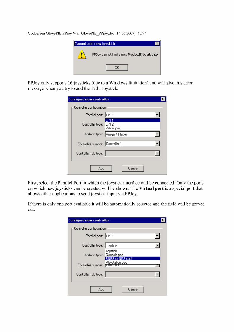
Godbersen GlovePIE PPjo
y Wii (GlovePIE_PPjoydoc 14062007) 4774
PPJoy only supports 16 joysticks (due to a Windows limitation) and will give this error message when you try to add the 17th Joystick
First select the Parallel Port to which the joystick interface will be connected Only the ports on which new joysticks can be created will be shown The Virtual port is a special port that allows other applications to send joystick input via PPJoy
If there is only one port available it will be automatically selected and the field will be greyed out
Godbersen GlovePIE PPjoy Wii (GlovePIE_PPjoydoc 14062007) 4874 Next select the type of controller that is you want to connect to the particular port The interfaces available (see below) will depend on the selection made here The following controller types are currently supported
bull Joystick Standard digital joystick like on Commodore 64 Amstrad Spectrum etc or any other device that does not fit into the categories below
bull Genesis pad This is for Sega GenesisMegadrive controllers bull SNES or NES pad Nintendo NES SNES or Virtual Gameboy controllers bull Playstation pad Playstation or Playstation 2 controllers bull Virtual joystick Joystick device emulated by a Win32 application (minidriver)
Only the Virtual joystick device will only be shown when the Virtual Port is selected as parallel port The other device types will be shown for normal parallel ports
You cannot have more than one controller type or interface type on a single port If there are already joysticks defined for a given port the Controller Type and Interface Type will automatically be selected and greyed out
Next select the interface type that will be connected to the port This field will be greyed out if there is already an interface type defined for the selected port The list of interfaces shown are dependent on the Controller Type selected above
Note that the Controller Type and Interface Type together determines which physical interface is used For example the DirectPad Pro interface for the Playstation Pad Controller Type is very different from the DirectPad Pro interface for the Joystick Controller type
Godbersen GlovePIE
PPjoy Wii (GlovePIE_PPjoydoc 14062007) 4974
If the selected interface allows more than joystick to be connected (eg TurboGraFX or Linux0802) this field will allow you to choose the specific joystick If the interface only caters for one joystick this field will be greyed out
The last field allows you to select the specific type of controller connected if applicable
Currently the SNES or NES pad and Genesis pad controller type require a sub type to be specified because the sub types are read in different ways
Sub types for SNES or NES pad
bull SNES or Virtual Gameboy bull NES
Sub types for Genesis pad
bull ABC and Start This is the earlier Genesis pad
Godbersen GlovePIE PPjoy Wii (GlovePIE_PPjoydoc 14062007) 5074
bull ABCXYZ Start and Mode This is the later Genesis pad with 6 buttons
Click on Add to add the joystick to the system The screenshots shown below are from Windows XP the sequence for Windows 2000 is very similar On Windows 98Me you will need your original CD as Windows 98Me needs to install a driver from the CD
Make sure that Install the software automatically (as shown) are selected and click on Next
Click on Continue Anyway (Windows XP) or Yes (Windows 2000) if a warning appears about unsigned drivers This will depend on your settings for driver signing
Godbersen GlovePIE PPjoy W
ii (GlovePIE_PPjoydoc 14062007) 5174
Click on Finish
Make sure that Install the software automatically (as shown) are selected and click on Next
Click on Finish
Godbersen GlovePIE PPjoy Wii (GlovePIE_PPjoydoc 14062007) 5274
Removing an existing joystick This document describes how to remove an existing joystick using the PPJoy Control Panel applet See Opening the Control Panel applet for information on how to open the PPJoy control Panel applet
To delete a joystick select a joystick from the list displayed in the PPJoy applet then click on Remove Remove will only be enabled after you have selected a joystick from the list
There are two options when deleting a joystick
Remove joystick config from DirectInput should normally be ticked If it is not ticked the rest of Windows will think the joystick is simply unplugged It may also lead to failure when adding additional joysticks
Remove joystick driver from the system determines whether to delete the PPJoy device driver for the specified joystick It can safely be unchecked PPJoy uses a pool of up to 16 device drivers for the joysticks it emulates and can reuse the driver of a deleted joystick
Click on OK to confirm the deletion
Godbersen GlovePIE PPjoy Wii (GlovePIE_PPjoydoc 14062007) 5374
Changing button and axis the mapping PPJoy allows you to completely change the way the joystick buttons and axes configured The following topics will explain the mapping process in more detail
bull Important concepts bull Changing the button and axis mapping of a joystick bull Deleting a joystick mapping
Important concepts There are three levels of mapping in PPJoy
bull The Default mapping is used when there is no more specific (interface or individual) mapping for a particular joystick
bull The Interface mapping mapping applies to all joysticks without individual mappings that connect to this interface type
bull Individual mappings apply to a single joystick
If an individual mapping is defined for a joystick it will always be used If a joystick has no individual mapping the interface mapping will be used instead If there is no individual or interface mapping for a joystick the built-in default mapping will be used
The joystick mapping is used to transform the raw digital and analog values that PPJoy reads from a joystick into button presses axis movements and POV direction
bull Controls with an on-off motion are read as digital values All the buttons and the axes on most of the supported joysticks fall into this category
bull Controls with a range of motion are read as analog values Currently the Playstation controllers FMS PPM RC and the virtual joystick can return analog values
A button press can be mapped in the following ways
bull As a digital value read from a joystick bull When an analog control is moved to its minimum position bull When an analog control is moved to its maximum position bull As nothing in which case the button will never be pressed
An axis can be mapped in the following ways
bull Directly as an analog value read from a joystick bull Reverse of the analog value read from a joystick bull Two digital values one for minimum and one for the maximum axis position bull As nothing in which case the axis will always be centred
A POV hat can be mapped in three ways
bull As four directions These directional input can be any combination of button presses or axis minmax movements
Godbersen GlovePIE PPjoy Wii (GlovePIE_PPjoydoc 14062007) 5474
bull As a continuous direction between 0 and 359 degrees In this case a single analog input is used
bull As nothing in which case the POV hat will report not pressed
PPJoy allows you change the number of buttons and axes and POV hats reported for a joystick By default only the virtual joystick and PSX controllers have a POV hat defined
Changing the button and axis mapping of a joystick
Start by selecting the joystick to change and click on the Mapping button A new dialog box similar to the one below should appear
Godbersen Gl
ovePIE PPjoy Wii (GlovePIE_PPjoydoc 14062007) 5574
Broadly there are two groups of options the interface (top three) and individual (bottom three) options If no mapping exists for a given category (interface or individual) you are offered the chance to create a mapping else you have to option to modify or delete the mapping See the section Deleting a mapping for more information on how to delete a joystick mapping
The interface mapping will affect all controllers using that interface type unless the controller has its own individual mapping Individual mappings will always take precedence over interface mappings
If you choose a Set (Create) or Modify option and click on Next you will see the screen below
Godbersen Gl
ovePIE PPjoy Wii (GlovePIE_PPjoydoc 14062007) 5674
This screen will show you the number of buttons axes and hats that PPJoy will report to Windows for this device It will also show you the HID types reported for the axes You can change the number of axes buttons and hats reported to DirectX as well as their types Older verions of DirectX does not like this and will cause DrWatson errors in the Game Controllers Control Panel and possibly other applications as well Changing these values with DirectX 9 installed on Windows XP seems to work fine
Click on Next to continue
Godbersen Gl
ovePIE PPjoy Wii (GlovePIE_PPjoydoc 14062007) 5774
This screen will allow you to change the mapping for each axis Note that playstation pads have two mapping modes - digital and analog mode After configuring the mapping for digital mode you will be shown the same screens to configure the mapping for analog mode Currently all other devices only have a single mapping mode
An axis can be mapped in one of the following ways
bull Directly as an analog value read from a joystick for example an analog Playstation pad (Analog xx in the drop-down list)
bull An analog value read from a joystick with the direction reversed (Analog xx rev in the drop-down list)
bull Two digital values (buttons or digital joystick axes) one for minimum and one for the maximum axis position (Digital xx in the drop-down list)
bull As nothing in which case the axis will always be centred (nothing in the drop-down list)
The easiest way to set the mapping for a particular axis is to click on the Scan button in the Min column next to the axis you want to change The following screen will appear
Godbersen GlovePIE PPjoy Wii (G
lovePIE_PPjoydoc 14062007) 5874
Now press the button or move the control in the minimum (up left) direction that you want to map to this axis As soon as PPJoy senses any button press or axis movement on the selected device it will close the scan dialog and update the mapping page (If a button is pressed or an axis moved before clicking on the scan button the mapping page will immediately be updated and the scan dialog will not appear)
When an analog value is selected in the Min column for an axis the Max column for that axis will be greyed out This is because a single analog value completely defines an axis When a digital value is entered in the axis minimum column another digital value must be specified in the maximum column for that axis
Most interfaces will report the following values for up down left and right
bull D 0 Joystick is pressed UP bull D 1 Joystick is pressed DOWN bull D 2 Joystick is pressed LEFT bull D 3 Joystick is pressed RIGHT
When all the axis mappings are configured click on Next This takes you to the button mapping page
Godbersen Gl
ovePIE PPjoy Wii (GlovePIE_PPjoydoc 14062007) 5974
The button mapping page operates similar to the axis mapping page A button can be mapped in the following ways
bull Directly as digital value read from a joystick (Digital xx in the drop-down list) bull An analog value set to its minimum value (position) (Analog xx min in the drop-
down list) bull An analog value set to its maximum value (position) (Analog xx max in the drop-
down list) bull As nothing in which case the button will never be pressed (nothing in the drop-down
list)
The scan button operates the same as it does on the axis mapping page
Click on Next when you configured all the buttons If the device has more than 16 buttons you will be shown the button mapping page again this time for buttons 17 to (possibly) 32 otherwise you will proceed to the POV hat mapping page If there is no POV hat defined for the device this page is skipped
Godbersen Gl
ovePIE PPjoy Wii (GlovePIE_PPjoydoc 14062007) 6074
If you select a directional button POV you must provide a mapping for 4 buttons The mapping for these direction buttons works exactly like the mapping of (fire) buttons on the previous page
For a continuous position POV you must provide an analog input for the POV - you cannot use any digital inputs here Just like for axes you can use the analog value in its normal and reversed senses Take note that very few devices provides analog inputs
If this device has more than one configuration (like playstation pads) the Next button will take you to the axis mapping page for the next mapping After you have finished configuring the POV hats for the last mapping mode you will be moved on to the finish screen
Godbersen GlovePIE PPjo
y Wii (GlovePIE_PPjoydoc 14062007) 6174
This screen confirms that the mapping is complete It is also your last chance to cancel without writing the mapping to the joystick driver Click on Finish to write the new mapping to the driver
Deleting a joystick mapping
Godbersen Gl
ovePIE PPjoy Wii (GlovePIE_PPjoydoc 14062007) 6274
Start by selecting a joystick and clicking on the Mapping button
Select whether you want to delete the individual mapping for a joystick or the interface mapping Then click on Next If a mapping does not exist the option to delete it will be greyed out
Godbersen Gl
ovePIE PPjoy Wii (GlovePIE_PPjoydoc 14062007) 6374
This is the confirmation screen before the delete You have to select Yes before the Finish button will be activated After you selected Yes click on Finish
Changing the joystick interface timing parameters Certain joystick interfaces require relatively long delays which uses a lot of CPU cycles to read the joystick PPJoy allows you to customise the timing values used in order to minimize the CPU usage
Below is a list of the joystick and gamepad interfaces that have configurable timing parameters
bull Genesis gamepads bull NESSNES gamepads bull Playstation controllers bull LPT-switch controller bull FMS PPM RC transmitter
The following topics will explain changing timing parameters in more detail
bull Important concepts bull Changing the joystick timing parameters bull Deleting timing parameters
Godbersen GlovePIE PPjoy Wii (GlovePIE_PPjoydoc 14062007) 6474 Important concepts There are three levels of timing parameters in PPJoy
bull The Default timing is used when there are no more specific (interface or individual) timing parameters for a particular joystick They are probably not optimal for your controller but should be adequate in most cases
bull The Interface timing applies to all joysticks without individual timings that connect to this interface type
bull Individual timing applies to a single joystick
If individual timing parameters are defined for a joystick they will always be used If a joystick has no individual timing parameters the interface timing will be used instead If there is no individual or interface timing for a joystick the built-in default timing parameters will be used
Different interfaces even for the same controller type have separate interface timing settings For example the DirectPad Pro and Linux interfaces for Playstation controllers will each have their own interface timing parameters
Changing the joystick timing parameters
Start by selecting the joystick to change and click on the Timing button A new dialog box similar to the one below should appear
Godbersen Gl
ovePIE PPjoy Wii (GlovePIE_PPjoydoc 14062007) 6574
Broadly there are two groups of options the interface (top three) and individual (bottom three) options If no timing parameters exist for a given category (interface or individual) you are offered the chance to create new timing parameters else you have to option to modify or delete them See the section Deleting timing parameters for more information on how to delete the timing parameters
The interface timing parameters will affect all controllers using that interface type unless the controller has its own individual parameters Individual timing parameters will always take precedence over interface parameters
If you choose a Set (Create) or Modify option and click on Next you will see a screen like the one below The exact screen will depend on the joystick type for which you want to modify the timing parameters
Godbersen Gl
ovePIE PPjoy Wii (GlovePIE_PPjoydoc 14062007) 6674
The top part of the screen will list the timing parameters available for the selected controller or interface and allow you to change them Click on Apply to activate the new parameters while keeping the wizard open Clicking on Finish will apply the new timing values and close the wizard
The best strategy to configure timing parameters is probably to gradually lower and apply one parameter until the controllers operation becomes unstable Repeat this process for the other parameters
Clicking on Reset defaults will change the timing parameters back to the values they were when the wizard was started and apply them
Click on Finish after modifying the timing parameters
Godbersen Glov
ePIE PPjoy Wii (GlovePIE_PPjoydoc 14062007) 6774
Deleting timing parameters
Start by selecting a joystick and clicking on the Timing button
Godbersen Gl
ovePIE PPjoy Wii (GlovePIE_PPjoydoc 14062007) 6874
Select whether you want to delete the individual timing parameters for a joystick or the interface timing parameters Then click on Next If timing parameters do not exist the option to delete it will be greyed out
Godbersen Gl
ovePIE PPjoy Wii (GlovePIE_PPjoydoc 14062007) 6974
This is the confirmation screen before the delete You have to select Yes before the Finish button will be activated After you selected Yes click on Finish
Introduction This page provides information on the timing parameters available to tune the way PPJoy scans various controller types
The following controller types have customisable timing parameters
bull Sega Genesis controllers bull LPT-switch controllers bull PPM RC transmitters bull Playstation controllers bull SNESNES controllers
Sega Genesis controller timing parameters The timing parameters presented below are applicable to all Genesys interfaces
Godb
ersen GlovePIE PPjoy Wii (GlovePIE_PPjoydoc 14062007) 7074
There are two protocols used to Sega Genesis controllers The protocol used depends on the controller subtype specified when the controller was added If you specify ABC and Start as the controller type the 3-button protocol will be used if you specify ABCXYZ Start and Mode the 6-button protocol is used
bull Genesis interbit delay specifies the number of microseconds delay between changing the state of the Select line and reading the joystick state when using the 3-button protocol
bull Genesis 6 button interbit delay specifies the number of microseconds delay between changing the state of the Select line and reading the joystick state when using the 6-button protocol
LPT-switch controller timing parameters The timing parameters presented below are applicable to the LPT-switch interface
Godbersen Glov
ePIE PPjoy Wii (GlovePIE_PPjoydoc 14062007) 7174
The LPTswitch interface has a single timing parameter LPTswitch row select delay This parameter specifies the delay in microseconds between setting the row-select line low and reading the column data from the interface
PPM RC transmitter timing parameters The timing parameters presented below are applicable to the PPM RC transmitter interface
The PPM RC IRQ interface measures the durations between two consecutive low-to-high transitions of the IRQ pin This means that PPJoy does not care whether the timing pulses are high or low (Normal or Inverted signal)
The three applicable timing parameters are
bull PPM min servo pulse width specifies the minimum duration in microseconds between timing pulses If the duration between two consecutive pulses is less than this value the corresponding joystick axis will report its minimum position
bull PPM max servo pulse width specifies the maximum duration in microseconds between timing pulses If the duration between two consecutive pulses is more than this value but less than the minimum sync pulse width the corresponding joystick axis will report its maximum position
Godbersen GlovePIE PPjoy Wii (GlovePIE_PPjoydoc 14062007) 7274
bull PPM min sync pulse width specifies the minimum duration in microseconds of the sync pulse An inter-pulse duration greater than this value marks the beginning of a new frame
Playstation timing parameters The timing parameters presented below are applicable to Playstation interfaces
The figure above is timing for the transfer of an entire data packet The diagram below details the transfer of a single byte between the PC and PSX controller
There are five parameters for Playstation controllers
bull PSX Sel delay specifies the duration in microseconds that the select signal will be taken low before the first byte is transferred
bull PSX Bit delay specifies the duration in microseconds the delay between setting the clock signal high and writing a bit to the controller and between setting the clock line low and reading a bit from the controller
bull PSX Ack1 delay specifies the maximum duration in microseconds to wait for an ACK pulse from the controller after transferring the first byte to the controller
bull PSX AckX delay specifies the maximum duration in microseconds to wait for an ACK pulse from the controller after transferring the second or later byte to the controller
bull PSX Tail delay specifies the duration in microseconds that the Select signal will remain low after the packet transfer between the PC and controller is completed
Godb
ersen GlovePIE PPjoy Wii (GlovePIE_PPjoydoc 14062007) 7374
SNESNES timing parameters The timing parameters presented below are applicable to all SNESNESVirtual Gameboy interfaces
SNESNES interfaces have two timing parameters
bull SNES setup delay specifies the duration in microseconds that the latch signal will be held high
bull SNES interbit delay specifies the duration in microseconds between changes in the signal Every two bit delays an input bit will be read from the controller
Setting PPJoy global options PPJoy has a number of global options that affects the operation of one or more interfaces The options screen shown below can be activated by clicking on the Options button in the main PPJoy screen
Currently PPJoy supports the following options
bull Debug PPM RC interface Setting this option causes PPJoy to make a click (toggle speaker state) every time it detects an incoming pulse from PPM interface (LPT IRQ triggered) When the interface is working properly you should hear a steady tone
Godbersen GlovePIE PPjoy Wii (GlovePIE_PPjoydoc 14062007) 7474
bull Debug Playstation interfaces Setting this option causes PPJoy to make a click each time it reads an invalidcorrupted data packet from a playstation controller
bull Dont allocate ports to assigned joysticks This option only affects PPJoy on Windows 2000 XP and 2003 When it is set PPJoy acts the same way is does on Windows 98 Me where it does not allocate a parallel port when a joystick is configured Thus you do not have to disable PPJoy to use a printer connected to the parallel port
It is recommended that you do not turn on this option Turning on this option may interfere with printing and will also disable the PPM RC interface You need to restart your computer for changes to this option to take effect
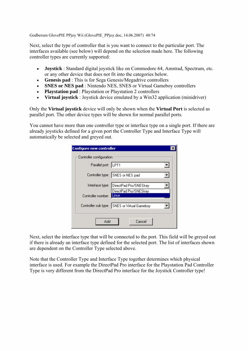
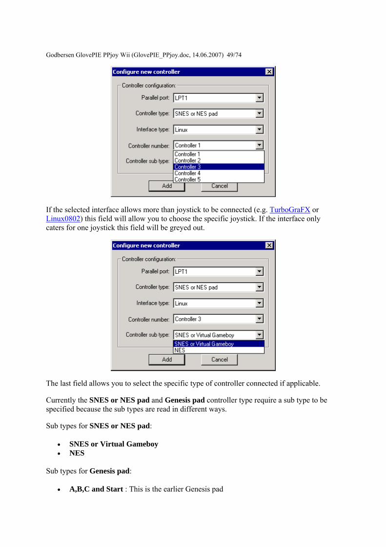
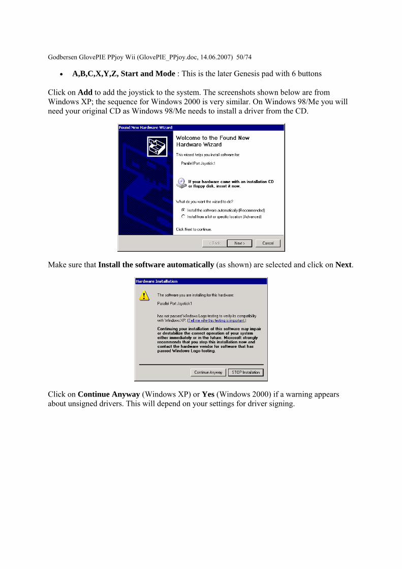
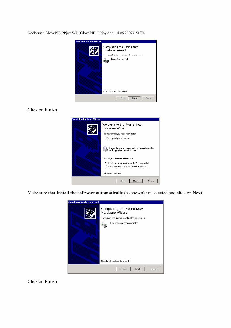
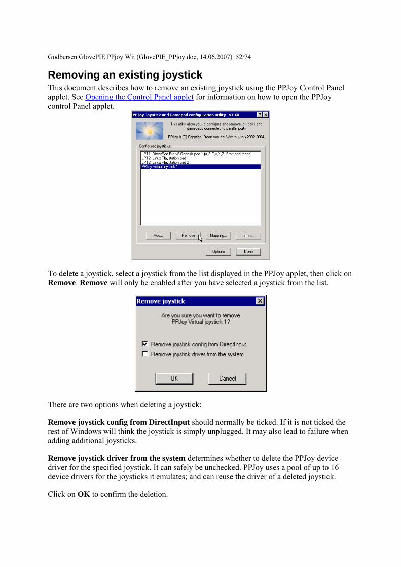
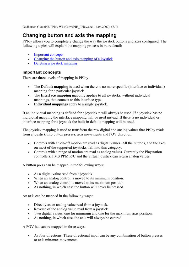
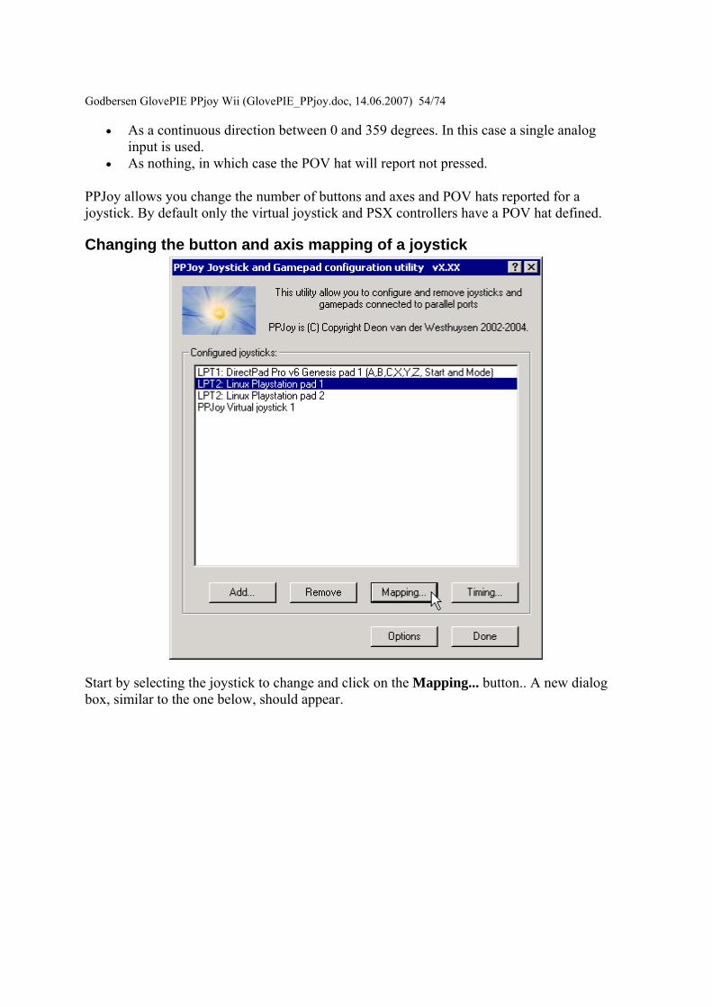
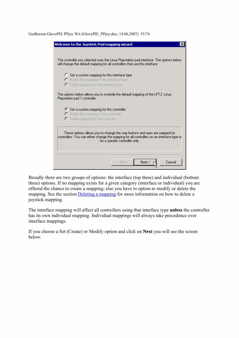
Godbersen Gl
ovePIE PPjoy Wii (GlovePIE_PPjoydoc 14062007) 5574
Broadly there are two groups of options the interface (top three) and individual (bottom three) options If no mapping exists for a given category (interface or individual) you are offered the chance to create a mapping else you have to option to modify or delete the mapping See the section Deleting a mapping for more information on how to delete a joystick mapping
The interface mapping will affect all controllers using that interface type unless the controller has its own individual mapping Individual mappings will always take precedence over interface mappings
If you choose a Set (Create) or Modify option and click on Next you will see the screen below
Godbersen Gl
ovePIE PPjoy Wii (GlovePIE_PPjoydoc 14062007) 5674
This screen will show you the number of buttons axes and hats that PPJoy will report to Windows for this device It will also show you the HID types reported for the axes You can change the number of axes buttons and hats reported to DirectX as well as their types Older verions of DirectX does not like this and will cause DrWatson errors in the Game Controllers Control Panel and possibly other applications as well Changing these values with DirectX 9 installed on Windows XP seems to work fine
Click on Next to continue
Godbersen Gl
ovePIE PPjoy Wii (GlovePIE_PPjoydoc 14062007) 5774
This screen will allow you to change the mapping for each axis Note that playstation pads have two mapping modes - digital and analog mode After configuring the mapping for digital mode you will be shown the same screens to configure the mapping for analog mode Currently all other devices only have a single mapping mode
An axis can be mapped in one of the following ways
bull Directly as an analog value read from a joystick for example an analog Playstation pad (Analog xx in the drop-down list)
bull An analog value read from a joystick with the direction reversed (Analog xx rev in the drop-down list)
bull Two digital values (buttons or digital joystick axes) one for minimum and one for the maximum axis position (Digital xx in the drop-down list)
bull As nothing in which case the axis will always be centred (nothing in the drop-down list)
The easiest way to set the mapping for a particular axis is to click on the Scan button in the Min column next to the axis you want to change The following screen will appear
Godbersen GlovePIE PPjoy Wii (G
lovePIE_PPjoydoc 14062007) 5874
Now press the button or move the control in the minimum (up left) direction that you want to map to this axis As soon as PPJoy senses any button press or axis movement on the selected device it will close the scan dialog and update the mapping page (If a button is pressed or an axis moved before clicking on the scan button the mapping page will immediately be updated and the scan dialog will not appear)
When an analog value is selected in the Min column for an axis the Max column for that axis will be greyed out This is because a single analog value completely defines an axis When a digital value is entered in the axis minimum column another digital value must be specified in the maximum column for that axis
Most interfaces will report the following values for up down left and right
bull D 0 Joystick is pressed UP bull D 1 Joystick is pressed DOWN bull D 2 Joystick is pressed LEFT bull D 3 Joystick is pressed RIGHT
When all the axis mappings are configured click on Next This takes you to the button mapping page
Godbersen Gl
ovePIE PPjoy Wii (GlovePIE_PPjoydoc 14062007) 5974
The button mapping page operates similar to the axis mapping page A button can be mapped in the following ways
bull Directly as digital value read from a joystick (Digital xx in the drop-down list) bull An analog value set to its minimum value (position) (Analog xx min in the drop-
down list) bull An analog value set to its maximum value (position) (Analog xx max in the drop-
down list) bull As nothing in which case the button will never be pressed (nothing in the drop-down
list)
The scan button operates the same as it does on the axis mapping page
Click on Next when you configured all the buttons If the device has more than 16 buttons you will be shown the button mapping page again this time for buttons 17 to (possibly) 32 otherwise you will proceed to the POV hat mapping page If there is no POV hat defined for the device this page is skipped
Godbersen Gl
ovePIE PPjoy Wii (GlovePIE_PPjoydoc 14062007) 6074
If you select a directional button POV you must provide a mapping for 4 buttons The mapping for these direction buttons works exactly like the mapping of (fire) buttons on the previous page
For a continuous position POV you must provide an analog input for the POV - you cannot use any digital inputs here Just like for axes you can use the analog value in its normal and reversed senses Take note that very few devices provides analog inputs
If this device has more than one configuration (like playstation pads) the Next button will take you to the axis mapping page for the next mapping After you have finished configuring the POV hats for the last mapping mode you will be moved on to the finish screen
Godbersen GlovePIE PPjo
y Wii (GlovePIE_PPjoydoc 14062007) 6174
This screen confirms that the mapping is complete It is also your last chance to cancel without writing the mapping to the joystick driver Click on Finish to write the new mapping to the driver
Deleting a joystick mapping
Godbersen Gl
ovePIE PPjoy Wii (GlovePIE_PPjoydoc 14062007) 6274
Start by selecting a joystick and clicking on the Mapping button
Select whether you want to delete the individual mapping for a joystick or the interface mapping Then click on Next If a mapping does not exist the option to delete it will be greyed out
Godbersen Gl
ovePIE PPjoy Wii (GlovePIE_PPjoydoc 14062007) 6374
This is the confirmation screen before the delete You have to select Yes before the Finish button will be activated After you selected Yes click on Finish
Changing the joystick interface timing parameters Certain joystick interfaces require relatively long delays which uses a lot of CPU cycles to read the joystick PPJoy allows you to customise the timing values used in order to minimize the CPU usage
Below is a list of the joystick and gamepad interfaces that have configurable timing parameters
bull Genesis gamepads bull NESSNES gamepads bull Playstation controllers bull LPT-switch controller bull FMS PPM RC transmitter
The following topics will explain changing timing parameters in more detail
bull Important concepts bull Changing the joystick timing parameters bull Deleting timing parameters
Godbersen GlovePIE PPjoy Wii (GlovePIE_PPjoydoc 14062007) 6474 Important concepts There are three levels of timing parameters in PPJoy
bull The Default timing is used when there are no more specific (interface or individual) timing parameters for a particular joystick They are probably not optimal for your controller but should be adequate in most cases
bull The Interface timing applies to all joysticks without individual timings that connect to this interface type
bull Individual timing applies to a single joystick
If individual timing parameters are defined for a joystick they will always be used If a joystick has no individual timing parameters the interface timing will be used instead If there is no individual or interface timing for a joystick the built-in default timing parameters will be used
Different interfaces even for the same controller type have separate interface timing settings For example the DirectPad Pro and Linux interfaces for Playstation controllers will each have their own interface timing parameters
Changing the joystick timing parameters
Start by selecting the joystick to change and click on the Timing button A new dialog box similar to the one below should appear
Godbersen Gl
ovePIE PPjoy Wii (GlovePIE_PPjoydoc 14062007) 6574
Broadly there are two groups of options the interface (top three) and individual (bottom three) options If no timing parameters exist for a given category (interface or individual) you are offered the chance to create new timing parameters else you have to option to modify or delete them See the section Deleting timing parameters for more information on how to delete the timing parameters
The interface timing parameters will affect all controllers using that interface type unless the controller has its own individual parameters Individual timing parameters will always take precedence over interface parameters
If you choose a Set (Create) or Modify option and click on Next you will see a screen like the one below The exact screen will depend on the joystick type for which you want to modify the timing parameters
Godbersen Gl
ovePIE PPjoy Wii (GlovePIE_PPjoydoc 14062007) 6674
The top part of the screen will list the timing parameters available for the selected controller or interface and allow you to change them Click on Apply to activate the new parameters while keeping the wizard open Clicking on Finish will apply the new timing values and close the wizard
The best strategy to configure timing parameters is probably to gradually lower and apply one parameter until the controllers operation becomes unstable Repeat this process for the other parameters
Clicking on Reset defaults will change the timing parameters back to the values they were when the wizard was started and apply them
Click on Finish after modifying the timing parameters
Godbersen Glov
ePIE PPjoy Wii (GlovePIE_PPjoydoc 14062007) 6774
Deleting timing parameters
Start by selecting a joystick and clicking on the Timing button
Godbersen Gl
ovePIE PPjoy Wii (GlovePIE_PPjoydoc 14062007) 6874
Select whether you want to delete the individual timing parameters for a joystick or the interface timing parameters Then click on Next If timing parameters do not exist the option to delete it will be greyed out
Godbersen Gl
ovePIE PPjoy Wii (GlovePIE_PPjoydoc 14062007) 6974
This is the confirmation screen before the delete You have to select Yes before the Finish button will be activated After you selected Yes click on Finish
Introduction This page provides information on the timing parameters available to tune the way PPJoy scans various controller types
The following controller types have customisable timing parameters
bull Sega Genesis controllers bull LPT-switch controllers bull PPM RC transmitters bull Playstation controllers bull SNESNES controllers
Sega Genesis controller timing parameters The timing parameters presented below are applicable to all Genesys interfaces
Godb
ersen GlovePIE PPjoy Wii (GlovePIE_PPjoydoc 14062007) 7074
There are two protocols used to Sega Genesis controllers The protocol used depends on the controller subtype specified when the controller was added If you specify ABC and Start as the controller type the 3-button protocol will be used if you specify ABCXYZ Start and Mode the 6-button protocol is used
bull Genesis interbit delay specifies the number of microseconds delay between changing the state of the Select line and reading the joystick state when using the 3-button protocol
bull Genesis 6 button interbit delay specifies the number of microseconds delay between changing the state of the Select line and reading the joystick state when using the 6-button protocol
LPT-switch controller timing parameters The timing parameters presented below are applicable to the LPT-switch interface
Godbersen Glov
ePIE PPjoy Wii (GlovePIE_PPjoydoc 14062007) 7174
The LPTswitch interface has a single timing parameter LPTswitch row select delay This parameter specifies the delay in microseconds between setting the row-select line low and reading the column data from the interface
PPM RC transmitter timing parameters The timing parameters presented below are applicable to the PPM RC transmitter interface
The PPM RC IRQ interface measures the durations between two consecutive low-to-high transitions of the IRQ pin This means that PPJoy does not care whether the timing pulses are high or low (Normal or Inverted signal)
The three applicable timing parameters are
bull PPM min servo pulse width specifies the minimum duration in microseconds between timing pulses If the duration between two consecutive pulses is less than this value the corresponding joystick axis will report its minimum position
bull PPM max servo pulse width specifies the maximum duration in microseconds between timing pulses If the duration between two consecutive pulses is more than this value but less than the minimum sync pulse width the corresponding joystick axis will report its maximum position
Godbersen GlovePIE PPjoy Wii (GlovePIE_PPjoydoc 14062007) 7274
bull PPM min sync pulse width specifies the minimum duration in microseconds of the sync pulse An inter-pulse duration greater than this value marks the beginning of a new frame
Playstation timing parameters The timing parameters presented below are applicable to Playstation interfaces
The figure above is timing for the transfer of an entire data packet The diagram below details the transfer of a single byte between the PC and PSX controller
There are five parameters for Playstation controllers
bull PSX Sel delay specifies the duration in microseconds that the select signal will be taken low before the first byte is transferred
bull PSX Bit delay specifies the duration in microseconds the delay between setting the clock signal high and writing a bit to the controller and between setting the clock line low and reading a bit from the controller
bull PSX Ack1 delay specifies the maximum duration in microseconds to wait for an ACK pulse from the controller after transferring the first byte to the controller
bull PSX AckX delay specifies the maximum duration in microseconds to wait for an ACK pulse from the controller after transferring the second or later byte to the controller
bull PSX Tail delay specifies the duration in microseconds that the Select signal will remain low after the packet transfer between the PC and controller is completed
Godb
ersen GlovePIE PPjoy Wii (GlovePIE_PPjoydoc 14062007) 7374
SNESNES timing parameters The timing parameters presented below are applicable to all SNESNESVirtual Gameboy interfaces
SNESNES interfaces have two timing parameters
bull SNES setup delay specifies the duration in microseconds that the latch signal will be held high
bull SNES interbit delay specifies the duration in microseconds between changes in the signal Every two bit delays an input bit will be read from the controller
Setting PPJoy global options PPJoy has a number of global options that affects the operation of one or more interfaces The options screen shown below can be activated by clicking on the Options button in the main PPJoy screen
Currently PPJoy supports the following options
bull Debug PPM RC interface Setting this option causes PPJoy to make a click (toggle speaker state) every time it detects an incoming pulse from PPM interface (LPT IRQ triggered) When the interface is working properly you should hear a steady tone
Godbersen GlovePIE PPjoy Wii (GlovePIE_PPjoydoc 14062007) 7474
bull Debug Playstation interfaces Setting this option causes PPJoy to make a click each time it reads an invalidcorrupted data packet from a playstation controller
bull Dont allocate ports to assigned joysticks This option only affects PPJoy on Windows 2000 XP and 2003 When it is set PPJoy acts the same way is does on Windows 98 Me where it does not allocate a parallel port when a joystick is configured Thus you do not have to disable PPJoy to use a printer connected to the parallel port
It is recommended that you do not turn on this option Turning on this option may interfere with printing and will also disable the PPM RC interface You need to restart your computer for changes to this option to take effect
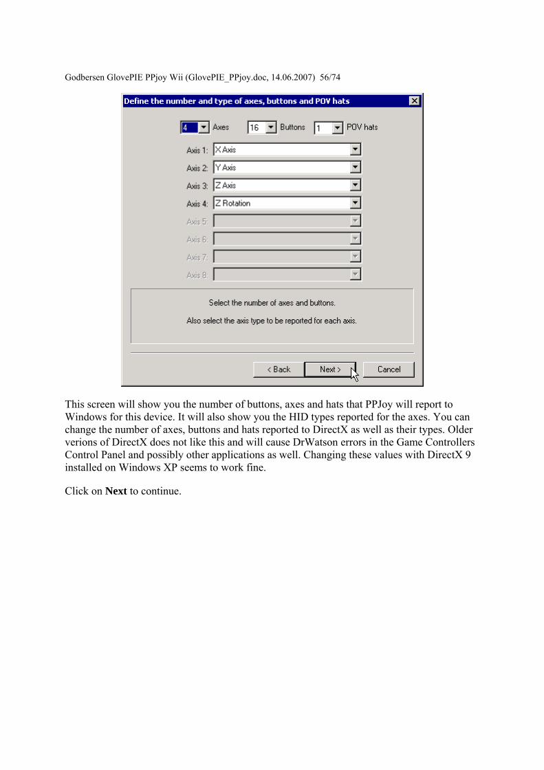
Godbersen Gl
ovePIE PPjoy Wii (GlovePIE_PPjoydoc 14062007) 5674
This screen will show you the number of buttons axes and hats that PPJoy will report to Windows for this device It will also show you the HID types reported for the axes You can change the number of axes buttons and hats reported to DirectX as well as their types Older verions of DirectX does not like this and will cause DrWatson errors in the Game Controllers Control Panel and possibly other applications as well Changing these values with DirectX 9 installed on Windows XP seems to work fine
Click on Next to continue
Godbersen Gl
ovePIE PPjoy Wii (GlovePIE_PPjoydoc 14062007) 5774
This screen will allow you to change the mapping for each axis Note that playstation pads have two mapping modes - digital and analog mode After configuring the mapping for digital mode you will be shown the same screens to configure the mapping for analog mode Currently all other devices only have a single mapping mode
An axis can be mapped in one of the following ways
bull Directly as an analog value read from a joystick for example an analog Playstation pad (Analog xx in the drop-down list)
bull An analog value read from a joystick with the direction reversed (Analog xx rev in the drop-down list)
bull Two digital values (buttons or digital joystick axes) one for minimum and one for the maximum axis position (Digital xx in the drop-down list)
bull As nothing in which case the axis will always be centred (nothing in the drop-down list)
The easiest way to set the mapping for a particular axis is to click on the Scan button in the Min column next to the axis you want to change The following screen will appear
Godbersen GlovePIE PPjoy Wii (G
lovePIE_PPjoydoc 14062007) 5874
Now press the button or move the control in the minimum (up left) direction that you want to map to this axis As soon as PPJoy senses any button press or axis movement on the selected device it will close the scan dialog and update the mapping page (If a button is pressed or an axis moved before clicking on the scan button the mapping page will immediately be updated and the scan dialog will not appear)
When an analog value is selected in the Min column for an axis the Max column for that axis will be greyed out This is because a single analog value completely defines an axis When a digital value is entered in the axis minimum column another digital value must be specified in the maximum column for that axis
Most interfaces will report the following values for up down left and right
bull D 0 Joystick is pressed UP bull D 1 Joystick is pressed DOWN bull D 2 Joystick is pressed LEFT bull D 3 Joystick is pressed RIGHT
When all the axis mappings are configured click on Next This takes you to the button mapping page
Godbersen Gl
ovePIE PPjoy Wii (GlovePIE_PPjoydoc 14062007) 5974
The button mapping page operates similar to the axis mapping page A button can be mapped in the following ways
bull Directly as digital value read from a joystick (Digital xx in the drop-down list) bull An analog value set to its minimum value (position) (Analog xx min in the drop-
down list) bull An analog value set to its maximum value (position) (Analog xx max in the drop-
down list) bull As nothing in which case the button will never be pressed (nothing in the drop-down
list)
The scan button operates the same as it does on the axis mapping page
Click on Next when you configured all the buttons If the device has more than 16 buttons you will be shown the button mapping page again this time for buttons 17 to (possibly) 32 otherwise you will proceed to the POV hat mapping page If there is no POV hat defined for the device this page is skipped
Godbersen Gl
ovePIE PPjoy Wii (GlovePIE_PPjoydoc 14062007) 6074
If you select a directional button POV you must provide a mapping for 4 buttons The mapping for these direction buttons works exactly like the mapping of (fire) buttons on the previous page
For a continuous position POV you must provide an analog input for the POV - you cannot use any digital inputs here Just like for axes you can use the analog value in its normal and reversed senses Take note that very few devices provides analog inputs
If this device has more than one configuration (like playstation pads) the Next button will take you to the axis mapping page for the next mapping After you have finished configuring the POV hats for the last mapping mode you will be moved on to the finish screen
Godbersen GlovePIE PPjo
y Wii (GlovePIE_PPjoydoc 14062007) 6174
This screen confirms that the mapping is complete It is also your last chance to cancel without writing the mapping to the joystick driver Click on Finish to write the new mapping to the driver
Deleting a joystick mapping
Godbersen Gl
ovePIE PPjoy Wii (GlovePIE_PPjoydoc 14062007) 6274
Start by selecting a joystick and clicking on the Mapping button
Select whether you want to delete the individual mapping for a joystick or the interface mapping Then click on Next If a mapping does not exist the option to delete it will be greyed out
Godbersen Gl
ovePIE PPjoy Wii (GlovePIE_PPjoydoc 14062007) 6374
This is the confirmation screen before the delete You have to select Yes before the Finish button will be activated After you selected Yes click on Finish
Changing the joystick interface timing parameters Certain joystick interfaces require relatively long delays which uses a lot of CPU cycles to read the joystick PPJoy allows you to customise the timing values used in order to minimize the CPU usage
Below is a list of the joystick and gamepad interfaces that have configurable timing parameters
bull Genesis gamepads bull NESSNES gamepads bull Playstation controllers bull LPT-switch controller bull FMS PPM RC transmitter
The following topics will explain changing timing parameters in more detail
bull Important concepts bull Changing the joystick timing parameters bull Deleting timing parameters
Godbersen GlovePIE PPjoy Wii (GlovePIE_PPjoydoc 14062007) 6474 Important concepts There are three levels of timing parameters in PPJoy
bull The Default timing is used when there are no more specific (interface or individual) timing parameters for a particular joystick They are probably not optimal for your controller but should be adequate in most cases
bull The Interface timing applies to all joysticks without individual timings that connect to this interface type
bull Individual timing applies to a single joystick
If individual timing parameters are defined for a joystick they will always be used If a joystick has no individual timing parameters the interface timing will be used instead If there is no individual or interface timing for a joystick the built-in default timing parameters will be used
Different interfaces even for the same controller type have separate interface timing settings For example the DirectPad Pro and Linux interfaces for Playstation controllers will each have their own interface timing parameters
Changing the joystick timing parameters
Start by selecting the joystick to change and click on the Timing button A new dialog box similar to the one below should appear
Godbersen Gl
ovePIE PPjoy Wii (GlovePIE_PPjoydoc 14062007) 6574
Broadly there are two groups of options the interface (top three) and individual (bottom three) options If no timing parameters exist for a given category (interface or individual) you are offered the chance to create new timing parameters else you have to option to modify or delete them See the section Deleting timing parameters for more information on how to delete the timing parameters
The interface timing parameters will affect all controllers using that interface type unless the controller has its own individual parameters Individual timing parameters will always take precedence over interface parameters
If you choose a Set (Create) or Modify option and click on Next you will see a screen like the one below The exact screen will depend on the joystick type for which you want to modify the timing parameters
Godbersen Gl
ovePIE PPjoy Wii (GlovePIE_PPjoydoc 14062007) 6674
The top part of the screen will list the timing parameters available for the selected controller or interface and allow you to change them Click on Apply to activate the new parameters while keeping the wizard open Clicking on Finish will apply the new timing values and close the wizard
The best strategy to configure timing parameters is probably to gradually lower and apply one parameter until the controllers operation becomes unstable Repeat this process for the other parameters
Clicking on Reset defaults will change the timing parameters back to the values they were when the wizard was started and apply them
Click on Finish after modifying the timing parameters
Godbersen Glov
ePIE PPjoy Wii (GlovePIE_PPjoydoc 14062007) 6774
Deleting timing parameters
Start by selecting a joystick and clicking on the Timing button
Godbersen Gl
ovePIE PPjoy Wii (GlovePIE_PPjoydoc 14062007) 6874
Select whether you want to delete the individual timing parameters for a joystick or the interface timing parameters Then click on Next If timing parameters do not exist the option to delete it will be greyed out
Godbersen Gl
ovePIE PPjoy Wii (GlovePIE_PPjoydoc 14062007) 6974
This is the confirmation screen before the delete You have to select Yes before the Finish button will be activated After you selected Yes click on Finish
Introduction This page provides information on the timing parameters available to tune the way PPJoy scans various controller types
The following controller types have customisable timing parameters
bull Sega Genesis controllers bull LPT-switch controllers bull PPM RC transmitters bull Playstation controllers bull SNESNES controllers
Sega Genesis controller timing parameters The timing parameters presented below are applicable to all Genesys interfaces
Godb
ersen GlovePIE PPjoy Wii (GlovePIE_PPjoydoc 14062007) 7074
There are two protocols used to Sega Genesis controllers The protocol used depends on the controller subtype specified when the controller was added If you specify ABC and Start as the controller type the 3-button protocol will be used if you specify ABCXYZ Start and Mode the 6-button protocol is used
bull Genesis interbit delay specifies the number of microseconds delay between changing the state of the Select line and reading the joystick state when using the 3-button protocol
bull Genesis 6 button interbit delay specifies the number of microseconds delay between changing the state of the Select line and reading the joystick state when using the 6-button protocol
LPT-switch controller timing parameters The timing parameters presented below are applicable to the LPT-switch interface
Godbersen Glov
ePIE PPjoy Wii (GlovePIE_PPjoydoc 14062007) 7174
The LPTswitch interface has a single timing parameter LPTswitch row select delay This parameter specifies the delay in microseconds between setting the row-select line low and reading the column data from the interface
PPM RC transmitter timing parameters The timing parameters presented below are applicable to the PPM RC transmitter interface
The PPM RC IRQ interface measures the durations between two consecutive low-to-high transitions of the IRQ pin This means that PPJoy does not care whether the timing pulses are high or low (Normal or Inverted signal)
The three applicable timing parameters are
bull PPM min servo pulse width specifies the minimum duration in microseconds between timing pulses If the duration between two consecutive pulses is less than this value the corresponding joystick axis will report its minimum position
bull PPM max servo pulse width specifies the maximum duration in microseconds between timing pulses If the duration between two consecutive pulses is more than this value but less than the minimum sync pulse width the corresponding joystick axis will report its maximum position
Godbersen GlovePIE PPjoy Wii (GlovePIE_PPjoydoc 14062007) 7274
bull PPM min sync pulse width specifies the minimum duration in microseconds of the sync pulse An inter-pulse duration greater than this value marks the beginning of a new frame
Playstation timing parameters The timing parameters presented below are applicable to Playstation interfaces
The figure above is timing for the transfer of an entire data packet The diagram below details the transfer of a single byte between the PC and PSX controller
There are five parameters for Playstation controllers
bull PSX Sel delay specifies the duration in microseconds that the select signal will be taken low before the first byte is transferred
bull PSX Bit delay specifies the duration in microseconds the delay between setting the clock signal high and writing a bit to the controller and between setting the clock line low and reading a bit from the controller
bull PSX Ack1 delay specifies the maximum duration in microseconds to wait for an ACK pulse from the controller after transferring the first byte to the controller
bull PSX AckX delay specifies the maximum duration in microseconds to wait for an ACK pulse from the controller after transferring the second or later byte to the controller
bull PSX Tail delay specifies the duration in microseconds that the Select signal will remain low after the packet transfer between the PC and controller is completed
Godb
ersen GlovePIE PPjoy Wii (GlovePIE_PPjoydoc 14062007) 7374
SNESNES timing parameters The timing parameters presented below are applicable to all SNESNESVirtual Gameboy interfaces
SNESNES interfaces have two timing parameters
bull SNES setup delay specifies the duration in microseconds that the latch signal will be held high
bull SNES interbit delay specifies the duration in microseconds between changes in the signal Every two bit delays an input bit will be read from the controller
Setting PPJoy global options PPJoy has a number of global options that affects the operation of one or more interfaces The options screen shown below can be activated by clicking on the Options button in the main PPJoy screen
Currently PPJoy supports the following options
bull Debug PPM RC interface Setting this option causes PPJoy to make a click (toggle speaker state) every time it detects an incoming pulse from PPM interface (LPT IRQ triggered) When the interface is working properly you should hear a steady tone
Godbersen GlovePIE PPjoy Wii (GlovePIE_PPjoydoc 14062007) 7474
bull Debug Playstation interfaces Setting this option causes PPJoy to make a click each time it reads an invalidcorrupted data packet from a playstation controller
bull Dont allocate ports to assigned joysticks This option only affects PPJoy on Windows 2000 XP and 2003 When it is set PPJoy acts the same way is does on Windows 98 Me where it does not allocate a parallel port when a joystick is configured Thus you do not have to disable PPJoy to use a printer connected to the parallel port
It is recommended that you do not turn on this option Turning on this option may interfere with printing and will also disable the PPM RC interface You need to restart your computer for changes to this option to take effect
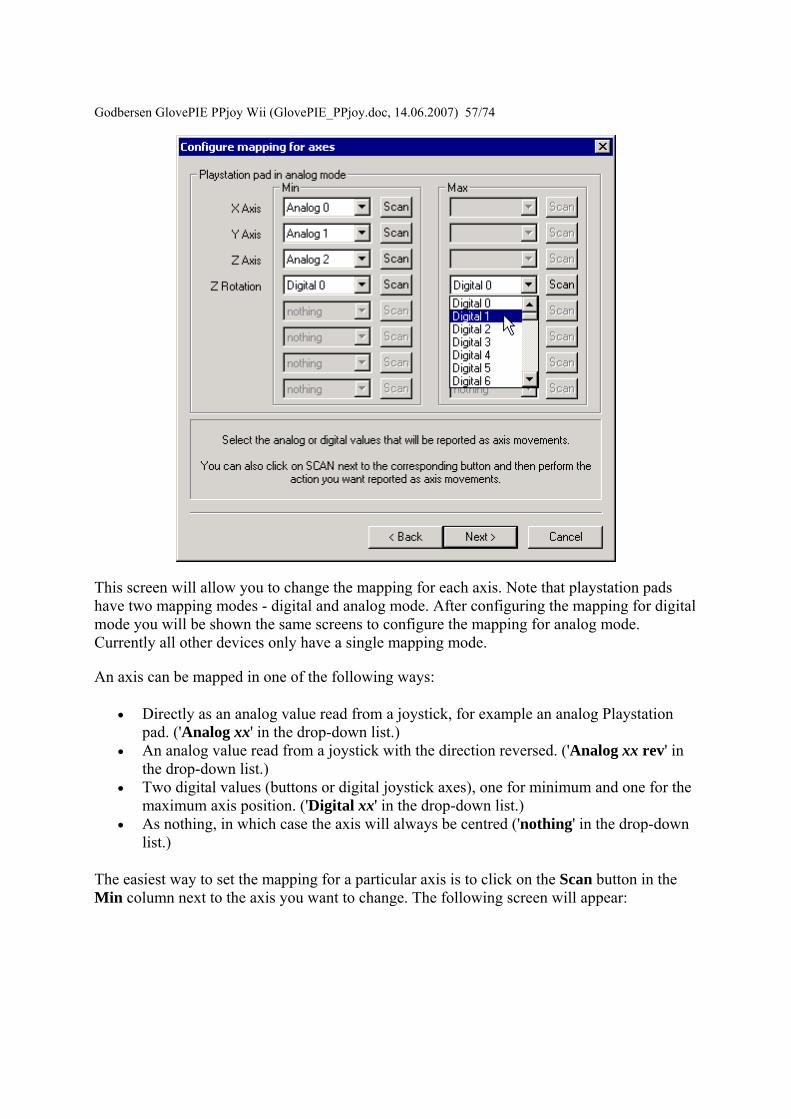
Godbersen Gl
ovePIE PPjoy Wii (GlovePIE_PPjoydoc 14062007) 5774
This screen will allow you to change the mapping for each axis Note that playstation pads have two mapping modes - digital and analog mode After configuring the mapping for digital mode you will be shown the same screens to configure the mapping for analog mode Currently all other devices only have a single mapping mode
An axis can be mapped in one of the following ways
bull Directly as an analog value read from a joystick for example an analog Playstation pad (Analog xx in the drop-down list)
bull An analog value read from a joystick with the direction reversed (Analog xx rev in the drop-down list)
bull Two digital values (buttons or digital joystick axes) one for minimum and one for the maximum axis position (Digital xx in the drop-down list)
bull As nothing in which case the axis will always be centred (nothing in the drop-down list)
The easiest way to set the mapping for a particular axis is to click on the Scan button in the Min column next to the axis you want to change The following screen will appear
Godbersen GlovePIE PPjoy Wii (G
lovePIE_PPjoydoc 14062007) 5874
Now press the button or move the control in the minimum (up left) direction that you want to map to this axis As soon as PPJoy senses any button press or axis movement on the selected device it will close the scan dialog and update the mapping page (If a button is pressed or an axis moved before clicking on the scan button the mapping page will immediately be updated and the scan dialog will not appear)
When an analog value is selected in the Min column for an axis the Max column for that axis will be greyed out This is because a single analog value completely defines an axis When a digital value is entered in the axis minimum column another digital value must be specified in the maximum column for that axis
Most interfaces will report the following values for up down left and right
bull D 0 Joystick is pressed UP bull D 1 Joystick is pressed DOWN bull D 2 Joystick is pressed LEFT bull D 3 Joystick is pressed RIGHT
When all the axis mappings are configured click on Next This takes you to the button mapping page
Godbersen Gl
ovePIE PPjoy Wii (GlovePIE_PPjoydoc 14062007) 5974
The button mapping page operates similar to the axis mapping page A button can be mapped in the following ways
bull Directly as digital value read from a joystick (Digital xx in the drop-down list) bull An analog value set to its minimum value (position) (Analog xx min in the drop-
down list) bull An analog value set to its maximum value (position) (Analog xx max in the drop-
down list) bull As nothing in which case the button will never be pressed (nothing in the drop-down
list)
The scan button operates the same as it does on the axis mapping page
Click on Next when you configured all the buttons If the device has more than 16 buttons you will be shown the button mapping page again this time for buttons 17 to (possibly) 32 otherwise you will proceed to the POV hat mapping page If there is no POV hat defined for the device this page is skipped
Godbersen Gl
ovePIE PPjoy Wii (GlovePIE_PPjoydoc 14062007) 6074
If you select a directional button POV you must provide a mapping for 4 buttons The mapping for these direction buttons works exactly like the mapping of (fire) buttons on the previous page
For a continuous position POV you must provide an analog input for the POV - you cannot use any digital inputs here Just like for axes you can use the analog value in its normal and reversed senses Take note that very few devices provides analog inputs
If this device has more than one configuration (like playstation pads) the Next button will take you to the axis mapping page for the next mapping After you have finished configuring the POV hats for the last mapping mode you will be moved on to the finish screen
Godbersen GlovePIE PPjo
y Wii (GlovePIE_PPjoydoc 14062007) 6174
This screen confirms that the mapping is complete It is also your last chance to cancel without writing the mapping to the joystick driver Click on Finish to write the new mapping to the driver
Deleting a joystick mapping
Godbersen Gl
ovePIE PPjoy Wii (GlovePIE_PPjoydoc 14062007) 6274
Start by selecting a joystick and clicking on the Mapping button
Select whether you want to delete the individual mapping for a joystick or the interface mapping Then click on Next If a mapping does not exist the option to delete it will be greyed out
Godbersen Gl
ovePIE PPjoy Wii (GlovePIE_PPjoydoc 14062007) 6374
This is the confirmation screen before the delete You have to select Yes before the Finish button will be activated After you selected Yes click on Finish
Changing the joystick interface timing parameters Certain joystick interfaces require relatively long delays which uses a lot of CPU cycles to read the joystick PPJoy allows you to customise the timing values used in order to minimize the CPU usage
Below is a list of the joystick and gamepad interfaces that have configurable timing parameters
bull Genesis gamepads bull NESSNES gamepads bull Playstation controllers bull LPT-switch controller bull FMS PPM RC transmitter
The following topics will explain changing timing parameters in more detail
bull Important concepts bull Changing the joystick timing parameters bull Deleting timing parameters
Godbersen GlovePIE PPjoy Wii (GlovePIE_PPjoydoc 14062007) 6474 Important concepts There are three levels of timing parameters in PPJoy
bull The Default timing is used when there are no more specific (interface or individual) timing parameters for a particular joystick They are probably not optimal for your controller but should be adequate in most cases
bull The Interface timing applies to all joysticks without individual timings that connect to this interface type
bull Individual timing applies to a single joystick
If individual timing parameters are defined for a joystick they will always be used If a joystick has no individual timing parameters the interface timing will be used instead If there is no individual or interface timing for a joystick the built-in default timing parameters will be used
Different interfaces even for the same controller type have separate interface timing settings For example the DirectPad Pro and Linux interfaces for Playstation controllers will each have their own interface timing parameters
Changing the joystick timing parameters
Start by selecting the joystick to change and click on the Timing button A new dialog box similar to the one below should appear
Godbersen Gl
ovePIE PPjoy Wii (GlovePIE_PPjoydoc 14062007) 6574
Broadly there are two groups of options the interface (top three) and individual (bottom three) options If no timing parameters exist for a given category (interface or individual) you are offered the chance to create new timing parameters else you have to option to modify or delete them See the section Deleting timing parameters for more information on how to delete the timing parameters
The interface timing parameters will affect all controllers using that interface type unless the controller has its own individual parameters Individual timing parameters will always take precedence over interface parameters
If you choose a Set (Create) or Modify option and click on Next you will see a screen like the one below The exact screen will depend on the joystick type for which you want to modify the timing parameters
Godbersen Gl
ovePIE PPjoy Wii (GlovePIE_PPjoydoc 14062007) 6674
The top part of the screen will list the timing parameters available for the selected controller or interface and allow you to change them Click on Apply to activate the new parameters while keeping the wizard open Clicking on Finish will apply the new timing values and close the wizard
The best strategy to configure timing parameters is probably to gradually lower and apply one parameter until the controllers operation becomes unstable Repeat this process for the other parameters
Clicking on Reset defaults will change the timing parameters back to the values they were when the wizard was started and apply them
Click on Finish after modifying the timing parameters
Godbersen Glov
ePIE PPjoy Wii (GlovePIE_PPjoydoc 14062007) 6774
Deleting timing parameters
Start by selecting a joystick and clicking on the Timing button
Godbersen Gl
ovePIE PPjoy Wii (GlovePIE_PPjoydoc 14062007) 6874
Select whether you want to delete the individual timing parameters for a joystick or the interface timing parameters Then click on Next If timing parameters do not exist the option to delete it will be greyed out
Godbersen Gl
ovePIE PPjoy Wii (GlovePIE_PPjoydoc 14062007) 6974
This is the confirmation screen before the delete You have to select Yes before the Finish button will be activated After you selected Yes click on Finish
Introduction This page provides information on the timing parameters available to tune the way PPJoy scans various controller types
The following controller types have customisable timing parameters
bull Sega Genesis controllers bull LPT-switch controllers bull PPM RC transmitters bull Playstation controllers bull SNESNES controllers
Sega Genesis controller timing parameters The timing parameters presented below are applicable to all Genesys interfaces
Godb
ersen GlovePIE PPjoy Wii (GlovePIE_PPjoydoc 14062007) 7074
There are two protocols used to Sega Genesis controllers The protocol used depends on the controller subtype specified when the controller was added If you specify ABC and Start as the controller type the 3-button protocol will be used if you specify ABCXYZ Start and Mode the 6-button protocol is used
bull Genesis interbit delay specifies the number of microseconds delay between changing the state of the Select line and reading the joystick state when using the 3-button protocol
bull Genesis 6 button interbit delay specifies the number of microseconds delay between changing the state of the Select line and reading the joystick state when using the 6-button protocol
LPT-switch controller timing parameters The timing parameters presented below are applicable to the LPT-switch interface
Godbersen Glov
ePIE PPjoy Wii (GlovePIE_PPjoydoc 14062007) 7174
The LPTswitch interface has a single timing parameter LPTswitch row select delay This parameter specifies the delay in microseconds between setting the row-select line low and reading the column data from the interface
PPM RC transmitter timing parameters The timing parameters presented below are applicable to the PPM RC transmitter interface
The PPM RC IRQ interface measures the durations between two consecutive low-to-high transitions of the IRQ pin This means that PPJoy does not care whether the timing pulses are high or low (Normal or Inverted signal)
The three applicable timing parameters are
bull PPM min servo pulse width specifies the minimum duration in microseconds between timing pulses If the duration between two consecutive pulses is less than this value the corresponding joystick axis will report its minimum position
bull PPM max servo pulse width specifies the maximum duration in microseconds between timing pulses If the duration between two consecutive pulses is more than this value but less than the minimum sync pulse width the corresponding joystick axis will report its maximum position
Godbersen GlovePIE PPjoy Wii (GlovePIE_PPjoydoc 14062007) 7274
bull PPM min sync pulse width specifies the minimum duration in microseconds of the sync pulse An inter-pulse duration greater than this value marks the beginning of a new frame
Playstation timing parameters The timing parameters presented below are applicable to Playstation interfaces
The figure above is timing for the transfer of an entire data packet The diagram below details the transfer of a single byte between the PC and PSX controller
There are five parameters for Playstation controllers
bull PSX Sel delay specifies the duration in microseconds that the select signal will be taken low before the first byte is transferred
bull PSX Bit delay specifies the duration in microseconds the delay between setting the clock signal high and writing a bit to the controller and between setting the clock line low and reading a bit from the controller
bull PSX Ack1 delay specifies the maximum duration in microseconds to wait for an ACK pulse from the controller after transferring the first byte to the controller
bull PSX AckX delay specifies the maximum duration in microseconds to wait for an ACK pulse from the controller after transferring the second or later byte to the controller
bull PSX Tail delay specifies the duration in microseconds that the Select signal will remain low after the packet transfer between the PC and controller is completed
Godb
ersen GlovePIE PPjoy Wii (GlovePIE_PPjoydoc 14062007) 7374
SNESNES timing parameters The timing parameters presented below are applicable to all SNESNESVirtual Gameboy interfaces
SNESNES interfaces have two timing parameters
bull SNES setup delay specifies the duration in microseconds that the latch signal will be held high
bull SNES interbit delay specifies the duration in microseconds between changes in the signal Every two bit delays an input bit will be read from the controller
Setting PPJoy global options PPJoy has a number of global options that affects the operation of one or more interfaces The options screen shown below can be activated by clicking on the Options button in the main PPJoy screen
Currently PPJoy supports the following options
bull Debug PPM RC interface Setting this option causes PPJoy to make a click (toggle speaker state) every time it detects an incoming pulse from PPM interface (LPT IRQ triggered) When the interface is working properly you should hear a steady tone
Godbersen GlovePIE PPjoy Wii (GlovePIE_PPjoydoc 14062007) 7474
bull Debug Playstation interfaces Setting this option causes PPJoy to make a click each time it reads an invalidcorrupted data packet from a playstation controller
bull Dont allocate ports to assigned joysticks This option only affects PPJoy on Windows 2000 XP and 2003 When it is set PPJoy acts the same way is does on Windows 98 Me where it does not allocate a parallel port when a joystick is configured Thus you do not have to disable PPJoy to use a printer connected to the parallel port
It is recommended that you do not turn on this option Turning on this option may interfere with printing and will also disable the PPM RC interface You need to restart your computer for changes to this option to take effect
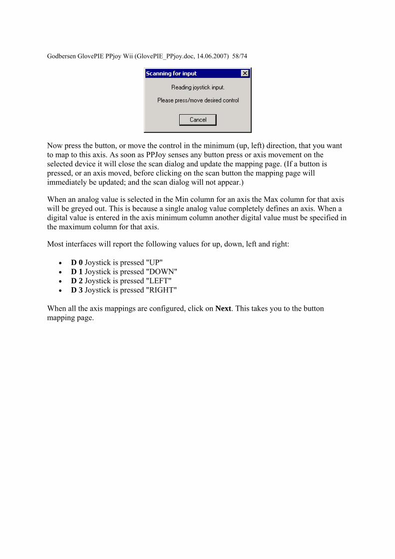
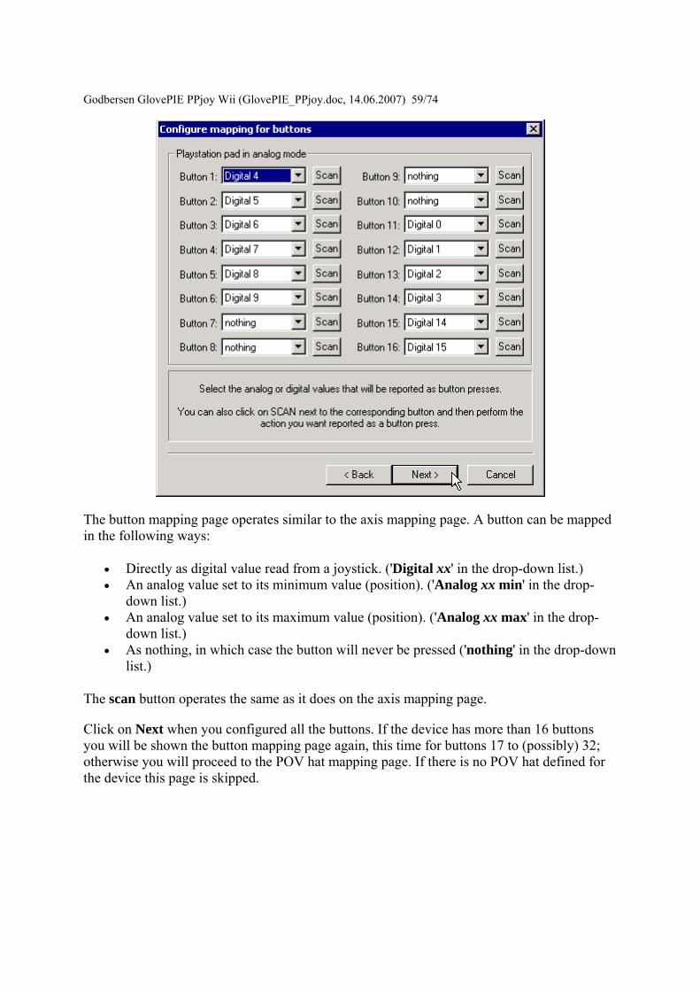
Godbersen Gl
ovePIE PPjoy Wii (GlovePIE_PPjoydoc 14062007) 5974
The button mapping page operates similar to the axis mapping page A button can be mapped in the following ways
bull Directly as digital value read from a joystick (Digital xx in the drop-down list) bull An analog value set to its minimum value (position) (Analog xx min in the drop-
down list) bull An analog value set to its maximum value (position) (Analog xx max in the drop-
down list) bull As nothing in which case the button will never be pressed (nothing in the drop-down
list)
The scan button operates the same as it does on the axis mapping page
Click on Next when you configured all the buttons If the device has more than 16 buttons you will be shown the button mapping page again this time for buttons 17 to (possibly) 32 otherwise you will proceed to the POV hat mapping page If there is no POV hat defined for the device this page is skipped
Godbersen Gl
ovePIE PPjoy Wii (GlovePIE_PPjoydoc 14062007) 6074
If you select a directional button POV you must provide a mapping for 4 buttons The mapping for these direction buttons works exactly like the mapping of (fire) buttons on the previous page
For a continuous position POV you must provide an analog input for the POV - you cannot use any digital inputs here Just like for axes you can use the analog value in its normal and reversed senses Take note that very few devices provides analog inputs
If this device has more than one configuration (like playstation pads) the Next button will take you to the axis mapping page for the next mapping After you have finished configuring the POV hats for the last mapping mode you will be moved on to the finish screen
Godbersen GlovePIE PPjo
y Wii (GlovePIE_PPjoydoc 14062007) 6174
This screen confirms that the mapping is complete It is also your last chance to cancel without writing the mapping to the joystick driver Click on Finish to write the new mapping to the driver
Deleting a joystick mapping
Godbersen Gl
ovePIE PPjoy Wii (GlovePIE_PPjoydoc 14062007) 6274
Start by selecting a joystick and clicking on the Mapping button
Select whether you want to delete the individual mapping for a joystick or the interface mapping Then click on Next If a mapping does not exist the option to delete it will be greyed out
Godbersen Gl
ovePIE PPjoy Wii (GlovePIE_PPjoydoc 14062007) 6374
This is the confirmation screen before the delete You have to select Yes before the Finish button will be activated After you selected Yes click on Finish
Changing the joystick interface timing parameters Certain joystick interfaces require relatively long delays which uses a lot of CPU cycles to read the joystick PPJoy allows you to customise the timing values used in order to minimize the CPU usage
Below is a list of the joystick and gamepad interfaces that have configurable timing parameters
bull Genesis gamepads bull NESSNES gamepads bull Playstation controllers bull LPT-switch controller bull FMS PPM RC transmitter
The following topics will explain changing timing parameters in more detail
bull Important concepts bull Changing the joystick timing parameters bull Deleting timing parameters
Godbersen GlovePIE PPjoy Wii (GlovePIE_PPjoydoc 14062007) 6474 Important concepts There are three levels of timing parameters in PPJoy
bull The Default timing is used when there are no more specific (interface or individual) timing parameters for a particular joystick They are probably not optimal for your controller but should be adequate in most cases
bull The Interface timing applies to all joysticks without individual timings that connect to this interface type
bull Individual timing applies to a single joystick
If individual timing parameters are defined for a joystick they will always be used If a joystick has no individual timing parameters the interface timing will be used instead If there is no individual or interface timing for a joystick the built-in default timing parameters will be used
Different interfaces even for the same controller type have separate interface timing settings For example the DirectPad Pro and Linux interfaces for Playstation controllers will each have their own interface timing parameters
Changing the joystick timing parameters
Start by selecting the joystick to change and click on the Timing button A new dialog box similar to the one below should appear
Godbersen Gl
ovePIE PPjoy Wii (GlovePIE_PPjoydoc 14062007) 6574
Broadly there are two groups of options the interface (top three) and individual (bottom three) options If no timing parameters exist for a given category (interface or individual) you are offered the chance to create new timing parameters else you have to option to modify or delete them See the section Deleting timing parameters for more information on how to delete the timing parameters
The interface timing parameters will affect all controllers using that interface type unless the controller has its own individual parameters Individual timing parameters will always take precedence over interface parameters
If you choose a Set (Create) or Modify option and click on Next you will see a screen like the one below The exact screen will depend on the joystick type for which you want to modify the timing parameters
Godbersen Gl
ovePIE PPjoy Wii (GlovePIE_PPjoydoc 14062007) 6674
The top part of the screen will list the timing parameters available for the selected controller or interface and allow you to change them Click on Apply to activate the new parameters while keeping the wizard open Clicking on Finish will apply the new timing values and close the wizard
The best strategy to configure timing parameters is probably to gradually lower and apply one parameter until the controllers operation becomes unstable Repeat this process for the other parameters
Clicking on Reset defaults will change the timing parameters back to the values they were when the wizard was started and apply them
Click on Finish after modifying the timing parameters
Godbersen Glov
ePIE PPjoy Wii (GlovePIE_PPjoydoc 14062007) 6774
Deleting timing parameters
Start by selecting a joystick and clicking on the Timing button
Godbersen Gl
ovePIE PPjoy Wii (GlovePIE_PPjoydoc 14062007) 6874
Select whether you want to delete the individual timing parameters for a joystick or the interface timing parameters Then click on Next If timing parameters do not exist the option to delete it will be greyed out
Godbersen Gl
ovePIE PPjoy Wii (GlovePIE_PPjoydoc 14062007) 6974
This is the confirmation screen before the delete You have to select Yes before the Finish button will be activated After you selected Yes click on Finish
Introduction This page provides information on the timing parameters available to tune the way PPJoy scans various controller types
The following controller types have customisable timing parameters
bull Sega Genesis controllers bull LPT-switch controllers bull PPM RC transmitters bull Playstation controllers bull SNESNES controllers
Sega Genesis controller timing parameters The timing parameters presented below are applicable to all Genesys interfaces
Godb
ersen GlovePIE PPjoy Wii (GlovePIE_PPjoydoc 14062007) 7074
There are two protocols used to Sega Genesis controllers The protocol used depends on the controller subtype specified when the controller was added If you specify ABC and Start as the controller type the 3-button protocol will be used if you specify ABCXYZ Start and Mode the 6-button protocol is used
bull Genesis interbit delay specifies the number of microseconds delay between changing the state of the Select line and reading the joystick state when using the 3-button protocol
bull Genesis 6 button interbit delay specifies the number of microseconds delay between changing the state of the Select line and reading the joystick state when using the 6-button protocol
LPT-switch controller timing parameters The timing parameters presented below are applicable to the LPT-switch interface
Godbersen Glov
ePIE PPjoy Wii (GlovePIE_PPjoydoc 14062007) 7174
The LPTswitch interface has a single timing parameter LPTswitch row select delay This parameter specifies the delay in microseconds between setting the row-select line low and reading the column data from the interface
PPM RC transmitter timing parameters The timing parameters presented below are applicable to the PPM RC transmitter interface
The PPM RC IRQ interface measures the durations between two consecutive low-to-high transitions of the IRQ pin This means that PPJoy does not care whether the timing pulses are high or low (Normal or Inverted signal)
The three applicable timing parameters are
bull PPM min servo pulse width specifies the minimum duration in microseconds between timing pulses If the duration between two consecutive pulses is less than this value the corresponding joystick axis will report its minimum position
bull PPM max servo pulse width specifies the maximum duration in microseconds between timing pulses If the duration between two consecutive pulses is more than this value but less than the minimum sync pulse width the corresponding joystick axis will report its maximum position
Godbersen GlovePIE PPjoy Wii (GlovePIE_PPjoydoc 14062007) 7274
bull PPM min sync pulse width specifies the minimum duration in microseconds of the sync pulse An inter-pulse duration greater than this value marks the beginning of a new frame
Playstation timing parameters The timing parameters presented below are applicable to Playstation interfaces
The figure above is timing for the transfer of an entire data packet The diagram below details the transfer of a single byte between the PC and PSX controller
There are five parameters for Playstation controllers
bull PSX Sel delay specifies the duration in microseconds that the select signal will be taken low before the first byte is transferred
bull PSX Bit delay specifies the duration in microseconds the delay between setting the clock signal high and writing a bit to the controller and between setting the clock line low and reading a bit from the controller
bull PSX Ack1 delay specifies the maximum duration in microseconds to wait for an ACK pulse from the controller after transferring the first byte to the controller
bull PSX AckX delay specifies the maximum duration in microseconds to wait for an ACK pulse from the controller after transferring the second or later byte to the controller
bull PSX Tail delay specifies the duration in microseconds that the Select signal will remain low after the packet transfer between the PC and controller is completed
Godb
ersen GlovePIE PPjoy Wii (GlovePIE_PPjoydoc 14062007) 7374
SNESNES timing parameters The timing parameters presented below are applicable to all SNESNESVirtual Gameboy interfaces
SNESNES interfaces have two timing parameters
bull SNES setup delay specifies the duration in microseconds that the latch signal will be held high
bull SNES interbit delay specifies the duration in microseconds between changes in the signal Every two bit delays an input bit will be read from the controller
Setting PPJoy global options PPJoy has a number of global options that affects the operation of one or more interfaces The options screen shown below can be activated by clicking on the Options button in the main PPJoy screen
Currently PPJoy supports the following options
bull Debug PPM RC interface Setting this option causes PPJoy to make a click (toggle speaker state) every time it detects an incoming pulse from PPM interface (LPT IRQ triggered) When the interface is working properly you should hear a steady tone
Godbersen GlovePIE PPjoy Wii (GlovePIE_PPjoydoc 14062007) 7474
bull Debug Playstation interfaces Setting this option causes PPJoy to make a click each time it reads an invalidcorrupted data packet from a playstation controller
bull Dont allocate ports to assigned joysticks This option only affects PPJoy on Windows 2000 XP and 2003 When it is set PPJoy acts the same way is does on Windows 98 Me where it does not allocate a parallel port when a joystick is configured Thus you do not have to disable PPJoy to use a printer connected to the parallel port
It is recommended that you do not turn on this option Turning on this option may interfere with printing and will also disable the PPM RC interface You need to restart your computer for changes to this option to take effect
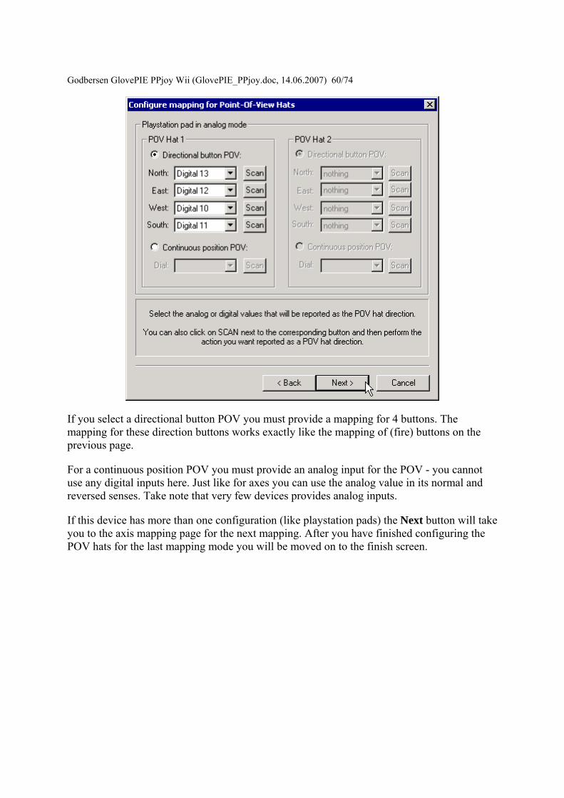
Godbersen Gl
ovePIE PPjoy Wii (GlovePIE_PPjoydoc 14062007) 6074
If you select a directional button POV you must provide a mapping for 4 buttons The mapping for these direction buttons works exactly like the mapping of (fire) buttons on the previous page
For a continuous position POV you must provide an analog input for the POV - you cannot use any digital inputs here Just like for axes you can use the analog value in its normal and reversed senses Take note that very few devices provides analog inputs
If this device has more than one configuration (like playstation pads) the Next button will take you to the axis mapping page for the next mapping After you have finished configuring the POV hats for the last mapping mode you will be moved on to the finish screen
Godbersen GlovePIE PPjo
y Wii (GlovePIE_PPjoydoc 14062007) 6174
This screen confirms that the mapping is complete It is also your last chance to cancel without writing the mapping to the joystick driver Click on Finish to write the new mapping to the driver
Deleting a joystick mapping
Godbersen Gl
ovePIE PPjoy Wii (GlovePIE_PPjoydoc 14062007) 6274
Start by selecting a joystick and clicking on the Mapping button
Select whether you want to delete the individual mapping for a joystick or the interface mapping Then click on Next If a mapping does not exist the option to delete it will be greyed out
Godbersen Gl
ovePIE PPjoy Wii (GlovePIE_PPjoydoc 14062007) 6374
This is the confirmation screen before the delete You have to select Yes before the Finish button will be activated After you selected Yes click on Finish
Changing the joystick interface timing parameters Certain joystick interfaces require relatively long delays which uses a lot of CPU cycles to read the joystick PPJoy allows you to customise the timing values used in order to minimize the CPU usage
Below is a list of the joystick and gamepad interfaces that have configurable timing parameters
bull Genesis gamepads bull NESSNES gamepads bull Playstation controllers bull LPT-switch controller bull FMS PPM RC transmitter
The following topics will explain changing timing parameters in more detail
bull Important concepts bull Changing the joystick timing parameters bull Deleting timing parameters
Godbersen GlovePIE PPjoy Wii (GlovePIE_PPjoydoc 14062007) 6474 Important concepts There are three levels of timing parameters in PPJoy
bull The Default timing is used when there are no more specific (interface or individual) timing parameters for a particular joystick They are probably not optimal for your controller but should be adequate in most cases
bull The Interface timing applies to all joysticks without individual timings that connect to this interface type
bull Individual timing applies to a single joystick
If individual timing parameters are defined for a joystick they will always be used If a joystick has no individual timing parameters the interface timing will be used instead If there is no individual or interface timing for a joystick the built-in default timing parameters will be used
Different interfaces even for the same controller type have separate interface timing settings For example the DirectPad Pro and Linux interfaces for Playstation controllers will each have their own interface timing parameters
Changing the joystick timing parameters
Start by selecting the joystick to change and click on the Timing button A new dialog box similar to the one below should appear
Godbersen Gl
ovePIE PPjoy Wii (GlovePIE_PPjoydoc 14062007) 6574
Broadly there are two groups of options the interface (top three) and individual (bottom three) options If no timing parameters exist for a given category (interface or individual) you are offered the chance to create new timing parameters else you have to option to modify or delete them See the section Deleting timing parameters for more information on how to delete the timing parameters
The interface timing parameters will affect all controllers using that interface type unless the controller has its own individual parameters Individual timing parameters will always take precedence over interface parameters
If you choose a Set (Create) or Modify option and click on Next you will see a screen like the one below The exact screen will depend on the joystick type for which you want to modify the timing parameters
Godbersen Gl
ovePIE PPjoy Wii (GlovePIE_PPjoydoc 14062007) 6674
The top part of the screen will list the timing parameters available for the selected controller or interface and allow you to change them Click on Apply to activate the new parameters while keeping the wizard open Clicking on Finish will apply the new timing values and close the wizard
The best strategy to configure timing parameters is probably to gradually lower and apply one parameter until the controllers operation becomes unstable Repeat this process for the other parameters
Clicking on Reset defaults will change the timing parameters back to the values they were when the wizard was started and apply them
Click on Finish after modifying the timing parameters
Godbersen Glov
ePIE PPjoy Wii (GlovePIE_PPjoydoc 14062007) 6774
Deleting timing parameters
Start by selecting a joystick and clicking on the Timing button
Godbersen Gl
ovePIE PPjoy Wii (GlovePIE_PPjoydoc 14062007) 6874
Select whether you want to delete the individual timing parameters for a joystick or the interface timing parameters Then click on Next If timing parameters do not exist the option to delete it will be greyed out
Godbersen Gl
ovePIE PPjoy Wii (GlovePIE_PPjoydoc 14062007) 6974
This is the confirmation screen before the delete You have to select Yes before the Finish button will be activated After you selected Yes click on Finish
Introduction This page provides information on the timing parameters available to tune the way PPJoy scans various controller types
The following controller types have customisable timing parameters
bull Sega Genesis controllers bull LPT-switch controllers bull PPM RC transmitters bull Playstation controllers bull SNESNES controllers
Sega Genesis controller timing parameters The timing parameters presented below are applicable to all Genesys interfaces
Godb
ersen GlovePIE PPjoy Wii (GlovePIE_PPjoydoc 14062007) 7074
There are two protocols used to Sega Genesis controllers The protocol used depends on the controller subtype specified when the controller was added If you specify ABC and Start as the controller type the 3-button protocol will be used if you specify ABCXYZ Start and Mode the 6-button protocol is used
bull Genesis interbit delay specifies the number of microseconds delay between changing the state of the Select line and reading the joystick state when using the 3-button protocol
bull Genesis 6 button interbit delay specifies the number of microseconds delay between changing the state of the Select line and reading the joystick state when using the 6-button protocol
LPT-switch controller timing parameters The timing parameters presented below are applicable to the LPT-switch interface
Godbersen Glov
ePIE PPjoy Wii (GlovePIE_PPjoydoc 14062007) 7174
The LPTswitch interface has a single timing parameter LPTswitch row select delay This parameter specifies the delay in microseconds between setting the row-select line low and reading the column data from the interface
PPM RC transmitter timing parameters The timing parameters presented below are applicable to the PPM RC transmitter interface
The PPM RC IRQ interface measures the durations between two consecutive low-to-high transitions of the IRQ pin This means that PPJoy does not care whether the timing pulses are high or low (Normal or Inverted signal)
The three applicable timing parameters are
bull PPM min servo pulse width specifies the minimum duration in microseconds between timing pulses If the duration between two consecutive pulses is less than this value the corresponding joystick axis will report its minimum position
bull PPM max servo pulse width specifies the maximum duration in microseconds between timing pulses If the duration between two consecutive pulses is more than this value but less than the minimum sync pulse width the corresponding joystick axis will report its maximum position
Godbersen GlovePIE PPjoy Wii (GlovePIE_PPjoydoc 14062007) 7274
bull PPM min sync pulse width specifies the minimum duration in microseconds of the sync pulse An inter-pulse duration greater than this value marks the beginning of a new frame
Playstation timing parameters The timing parameters presented below are applicable to Playstation interfaces
The figure above is timing for the transfer of an entire data packet The diagram below details the transfer of a single byte between the PC and PSX controller
There are five parameters for Playstation controllers
bull PSX Sel delay specifies the duration in microseconds that the select signal will be taken low before the first byte is transferred
bull PSX Bit delay specifies the duration in microseconds the delay between setting the clock signal high and writing a bit to the controller and between setting the clock line low and reading a bit from the controller
bull PSX Ack1 delay specifies the maximum duration in microseconds to wait for an ACK pulse from the controller after transferring the first byte to the controller
bull PSX AckX delay specifies the maximum duration in microseconds to wait for an ACK pulse from the controller after transferring the second or later byte to the controller
bull PSX Tail delay specifies the duration in microseconds that the Select signal will remain low after the packet transfer between the PC and controller is completed
Godb
ersen GlovePIE PPjoy Wii (GlovePIE_PPjoydoc 14062007) 7374
SNESNES timing parameters The timing parameters presented below are applicable to all SNESNESVirtual Gameboy interfaces
SNESNES interfaces have two timing parameters
bull SNES setup delay specifies the duration in microseconds that the latch signal will be held high
bull SNES interbit delay specifies the duration in microseconds between changes in the signal Every two bit delays an input bit will be read from the controller
Setting PPJoy global options PPJoy has a number of global options that affects the operation of one or more interfaces The options screen shown below can be activated by clicking on the Options button in the main PPJoy screen
Currently PPJoy supports the following options
bull Debug PPM RC interface Setting this option causes PPJoy to make a click (toggle speaker state) every time it detects an incoming pulse from PPM interface (LPT IRQ triggered) When the interface is working properly you should hear a steady tone
Godbersen GlovePIE PPjoy Wii (GlovePIE_PPjoydoc 14062007) 7474
bull Debug Playstation interfaces Setting this option causes PPJoy to make a click each time it reads an invalidcorrupted data packet from a playstation controller
bull Dont allocate ports to assigned joysticks This option only affects PPJoy on Windows 2000 XP and 2003 When it is set PPJoy acts the same way is does on Windows 98 Me where it does not allocate a parallel port when a joystick is configured Thus you do not have to disable PPJoy to use a printer connected to the parallel port
It is recommended that you do not turn on this option Turning on this option may interfere with printing and will also disable the PPM RC interface You need to restart your computer for changes to this option to take effect
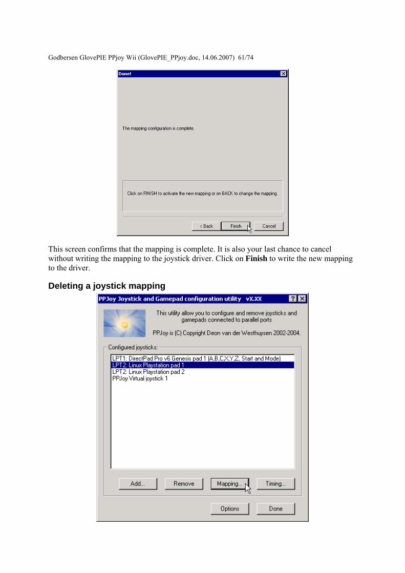
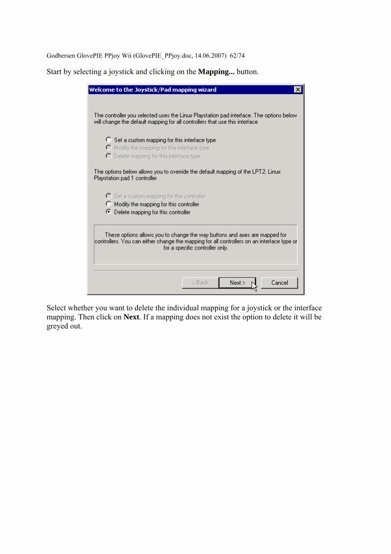
Godbersen Gl
ovePIE PPjoy Wii (GlovePIE_PPjoydoc 14062007) 6274
Start by selecting a joystick and clicking on the Mapping button
Select whether you want to delete the individual mapping for a joystick or the interface mapping Then click on Next If a mapping does not exist the option to delete it will be greyed out
Godbersen Gl
ovePIE PPjoy Wii (GlovePIE_PPjoydoc 14062007) 6374
This is the confirmation screen before the delete You have to select Yes before the Finish button will be activated After you selected Yes click on Finish
Changing the joystick interface timing parameters Certain joystick interfaces require relatively long delays which uses a lot of CPU cycles to read the joystick PPJoy allows you to customise the timing values used in order to minimize the CPU usage
Below is a list of the joystick and gamepad interfaces that have configurable timing parameters
bull Genesis gamepads bull NESSNES gamepads bull Playstation controllers bull LPT-switch controller bull FMS PPM RC transmitter
The following topics will explain changing timing parameters in more detail
bull Important concepts bull Changing the joystick timing parameters bull Deleting timing parameters
Godbersen GlovePIE PPjoy Wii (GlovePIE_PPjoydoc 14062007) 6474 Important concepts There are three levels of timing parameters in PPJoy
bull The Default timing is used when there are no more specific (interface or individual) timing parameters for a particular joystick They are probably not optimal for your controller but should be adequate in most cases
bull The Interface timing applies to all joysticks without individual timings that connect to this interface type
bull Individual timing applies to a single joystick
If individual timing parameters are defined for a joystick they will always be used If a joystick has no individual timing parameters the interface timing will be used instead If there is no individual or interface timing for a joystick the built-in default timing parameters will be used
Different interfaces even for the same controller type have separate interface timing settings For example the DirectPad Pro and Linux interfaces for Playstation controllers will each have their own interface timing parameters
Changing the joystick timing parameters
Start by selecting the joystick to change and click on the Timing button A new dialog box similar to the one below should appear
Godbersen Gl
ovePIE PPjoy Wii (GlovePIE_PPjoydoc 14062007) 6574
Broadly there are two groups of options the interface (top three) and individual (bottom three) options If no timing parameters exist for a given category (interface or individual) you are offered the chance to create new timing parameters else you have to option to modify or delete them See the section Deleting timing parameters for more information on how to delete the timing parameters
The interface timing parameters will affect all controllers using that interface type unless the controller has its own individual parameters Individual timing parameters will always take precedence over interface parameters
If you choose a Set (Create) or Modify option and click on Next you will see a screen like the one below The exact screen will depend on the joystick type for which you want to modify the timing parameters
Godbersen Gl
ovePIE PPjoy Wii (GlovePIE_PPjoydoc 14062007) 6674
The top part of the screen will list the timing parameters available for the selected controller or interface and allow you to change them Click on Apply to activate the new parameters while keeping the wizard open Clicking on Finish will apply the new timing values and close the wizard
The best strategy to configure timing parameters is probably to gradually lower and apply one parameter until the controllers operation becomes unstable Repeat this process for the other parameters
Clicking on Reset defaults will change the timing parameters back to the values they were when the wizard was started and apply them
Click on Finish after modifying the timing parameters
Godbersen Glov
ePIE PPjoy Wii (GlovePIE_PPjoydoc 14062007) 6774
Deleting timing parameters
Start by selecting a joystick and clicking on the Timing button
Godbersen Gl
ovePIE PPjoy Wii (GlovePIE_PPjoydoc 14062007) 6874
Select whether you want to delete the individual timing parameters for a joystick or the interface timing parameters Then click on Next If timing parameters do not exist the option to delete it will be greyed out
Godbersen Gl
ovePIE PPjoy Wii (GlovePIE_PPjoydoc 14062007) 6974
This is the confirmation screen before the delete You have to select Yes before the Finish button will be activated After you selected Yes click on Finish
Introduction This page provides information on the timing parameters available to tune the way PPJoy scans various controller types
The following controller types have customisable timing parameters
bull Sega Genesis controllers bull LPT-switch controllers bull PPM RC transmitters bull Playstation controllers bull SNESNES controllers
Sega Genesis controller timing parameters The timing parameters presented below are applicable to all Genesys interfaces
Godb
ersen GlovePIE PPjoy Wii (GlovePIE_PPjoydoc 14062007) 7074
There are two protocols used to Sega Genesis controllers The protocol used depends on the controller subtype specified when the controller was added If you specify ABC and Start as the controller type the 3-button protocol will be used if you specify ABCXYZ Start and Mode the 6-button protocol is used
bull Genesis interbit delay specifies the number of microseconds delay between changing the state of the Select line and reading the joystick state when using the 3-button protocol
bull Genesis 6 button interbit delay specifies the number of microseconds delay between changing the state of the Select line and reading the joystick state when using the 6-button protocol
LPT-switch controller timing parameters The timing parameters presented below are applicable to the LPT-switch interface
Godbersen Glov
ePIE PPjoy Wii (GlovePIE_PPjoydoc 14062007) 7174
The LPTswitch interface has a single timing parameter LPTswitch row select delay This parameter specifies the delay in microseconds between setting the row-select line low and reading the column data from the interface
PPM RC transmitter timing parameters The timing parameters presented below are applicable to the PPM RC transmitter interface
The PPM RC IRQ interface measures the durations between two consecutive low-to-high transitions of the IRQ pin This means that PPJoy does not care whether the timing pulses are high or low (Normal or Inverted signal)
The three applicable timing parameters are
bull PPM min servo pulse width specifies the minimum duration in microseconds between timing pulses If the duration between two consecutive pulses is less than this value the corresponding joystick axis will report its minimum position
bull PPM max servo pulse width specifies the maximum duration in microseconds between timing pulses If the duration between two consecutive pulses is more than this value but less than the minimum sync pulse width the corresponding joystick axis will report its maximum position
Godbersen GlovePIE PPjoy Wii (GlovePIE_PPjoydoc 14062007) 7274
bull PPM min sync pulse width specifies the minimum duration in microseconds of the sync pulse An inter-pulse duration greater than this value marks the beginning of a new frame
Playstation timing parameters The timing parameters presented below are applicable to Playstation interfaces
The figure above is timing for the transfer of an entire data packet The diagram below details the transfer of a single byte between the PC and PSX controller
There are five parameters for Playstation controllers
bull PSX Sel delay specifies the duration in microseconds that the select signal will be taken low before the first byte is transferred
bull PSX Bit delay specifies the duration in microseconds the delay between setting the clock signal high and writing a bit to the controller and between setting the clock line low and reading a bit from the controller
bull PSX Ack1 delay specifies the maximum duration in microseconds to wait for an ACK pulse from the controller after transferring the first byte to the controller
bull PSX AckX delay specifies the maximum duration in microseconds to wait for an ACK pulse from the controller after transferring the second or later byte to the controller
bull PSX Tail delay specifies the duration in microseconds that the Select signal will remain low after the packet transfer between the PC and controller is completed
Godb
ersen GlovePIE PPjoy Wii (GlovePIE_PPjoydoc 14062007) 7374
SNESNES timing parameters The timing parameters presented below are applicable to all SNESNESVirtual Gameboy interfaces
SNESNES interfaces have two timing parameters
bull SNES setup delay specifies the duration in microseconds that the latch signal will be held high
bull SNES interbit delay specifies the duration in microseconds between changes in the signal Every two bit delays an input bit will be read from the controller
Setting PPJoy global options PPJoy has a number of global options that affects the operation of one or more interfaces The options screen shown below can be activated by clicking on the Options button in the main PPJoy screen
Currently PPJoy supports the following options
bull Debug PPM RC interface Setting this option causes PPJoy to make a click (toggle speaker state) every time it detects an incoming pulse from PPM interface (LPT IRQ triggered) When the interface is working properly you should hear a steady tone
Godbersen GlovePIE PPjoy Wii (GlovePIE_PPjoydoc 14062007) 7474
bull Debug Playstation interfaces Setting this option causes PPJoy to make a click each time it reads an invalidcorrupted data packet from a playstation controller
bull Dont allocate ports to assigned joysticks This option only affects PPJoy on Windows 2000 XP and 2003 When it is set PPJoy acts the same way is does on Windows 98 Me where it does not allocate a parallel port when a joystick is configured Thus you do not have to disable PPJoy to use a printer connected to the parallel port
It is recommended that you do not turn on this option Turning on this option may interfere with printing and will also disable the PPM RC interface You need to restart your computer for changes to this option to take effect
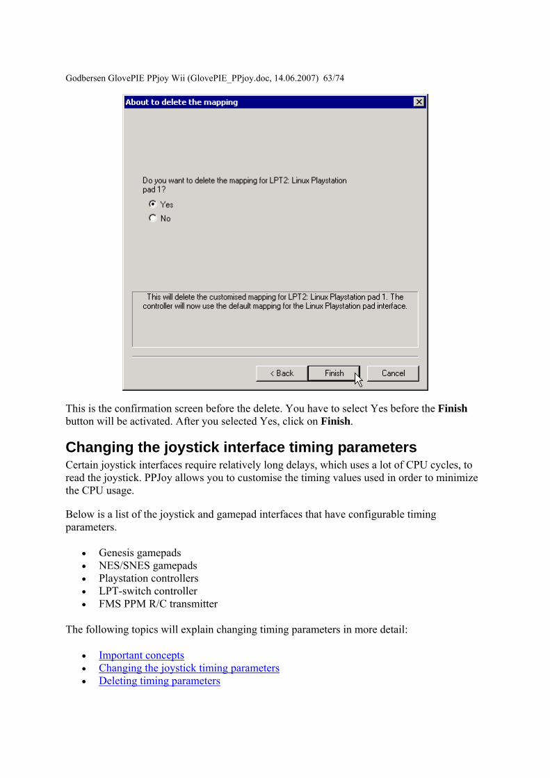
Godbersen Gl
ovePIE PPjoy Wii (GlovePIE_PPjoydoc 14062007) 6374
This is the confirmation screen before the delete You have to select Yes before the Finish button will be activated After you selected Yes click on Finish
Changing the joystick interface timing parameters Certain joystick interfaces require relatively long delays which uses a lot of CPU cycles to read the joystick PPJoy allows you to customise the timing values used in order to minimize the CPU usage
Below is a list of the joystick and gamepad interfaces that have configurable timing parameters
bull Genesis gamepads bull NESSNES gamepads bull Playstation controllers bull LPT-switch controller bull FMS PPM RC transmitter
The following topics will explain changing timing parameters in more detail
bull Important concepts bull Changing the joystick timing parameters bull Deleting timing parameters
Godbersen GlovePIE PPjoy Wii (GlovePIE_PPjoydoc 14062007) 6474 Important concepts There are three levels of timing parameters in PPJoy
bull The Default timing is used when there are no more specific (interface or individual) timing parameters for a particular joystick They are probably not optimal for your controller but should be adequate in most cases
bull The Interface timing applies to all joysticks without individual timings that connect to this interface type
bull Individual timing applies to a single joystick
If individual timing parameters are defined for a joystick they will always be used If a joystick has no individual timing parameters the interface timing will be used instead If there is no individual or interface timing for a joystick the built-in default timing parameters will be used
Different interfaces even for the same controller type have separate interface timing settings For example the DirectPad Pro and Linux interfaces for Playstation controllers will each have their own interface timing parameters
Changing the joystick timing parameters
Start by selecting the joystick to change and click on the Timing button A new dialog box similar to the one below should appear
Godbersen Gl
ovePIE PPjoy Wii (GlovePIE_PPjoydoc 14062007) 6574
Broadly there are two groups of options the interface (top three) and individual (bottom three) options If no timing parameters exist for a given category (interface or individual) you are offered the chance to create new timing parameters else you have to option to modify or delete them See the section Deleting timing parameters for more information on how to delete the timing parameters
The interface timing parameters will affect all controllers using that interface type unless the controller has its own individual parameters Individual timing parameters will always take precedence over interface parameters
If you choose a Set (Create) or Modify option and click on Next you will see a screen like the one below The exact screen will depend on the joystick type for which you want to modify the timing parameters
Godbersen Gl
ovePIE PPjoy Wii (GlovePIE_PPjoydoc 14062007) 6674
The top part of the screen will list the timing parameters available for the selected controller or interface and allow you to change them Click on Apply to activate the new parameters while keeping the wizard open Clicking on Finish will apply the new timing values and close the wizard
The best strategy to configure timing parameters is probably to gradually lower and apply one parameter until the controllers operation becomes unstable Repeat this process for the other parameters
Clicking on Reset defaults will change the timing parameters back to the values they were when the wizard was started and apply them
Click on Finish after modifying the timing parameters
Godbersen Glov
ePIE PPjoy Wii (GlovePIE_PPjoydoc 14062007) 6774
Deleting timing parameters
Start by selecting a joystick and clicking on the Timing button
Godbersen Gl
ovePIE PPjoy Wii (GlovePIE_PPjoydoc 14062007) 6874
Select whether you want to delete the individual timing parameters for a joystick or the interface timing parameters Then click on Next If timing parameters do not exist the option to delete it will be greyed out
Godbersen Gl
ovePIE PPjoy Wii (GlovePIE_PPjoydoc 14062007) 6974
This is the confirmation screen before the delete You have to select Yes before the Finish button will be activated After you selected Yes click on Finish
Introduction This page provides information on the timing parameters available to tune the way PPJoy scans various controller types
The following controller types have customisable timing parameters
bull Sega Genesis controllers bull LPT-switch controllers bull PPM RC transmitters bull Playstation controllers bull SNESNES controllers
Sega Genesis controller timing parameters The timing parameters presented below are applicable to all Genesys interfaces
Godb
ersen GlovePIE PPjoy Wii (GlovePIE_PPjoydoc 14062007) 7074
There are two protocols used to Sega Genesis controllers The protocol used depends on the controller subtype specified when the controller was added If you specify ABC and Start as the controller type the 3-button protocol will be used if you specify ABCXYZ Start and Mode the 6-button protocol is used
bull Genesis interbit delay specifies the number of microseconds delay between changing the state of the Select line and reading the joystick state when using the 3-button protocol
bull Genesis 6 button interbit delay specifies the number of microseconds delay between changing the state of the Select line and reading the joystick state when using the 6-button protocol
LPT-switch controller timing parameters The timing parameters presented below are applicable to the LPT-switch interface
Godbersen Glov
ePIE PPjoy Wii (GlovePIE_PPjoydoc 14062007) 7174
The LPTswitch interface has a single timing parameter LPTswitch row select delay This parameter specifies the delay in microseconds between setting the row-select line low and reading the column data from the interface
PPM RC transmitter timing parameters The timing parameters presented below are applicable to the PPM RC transmitter interface
The PPM RC IRQ interface measures the durations between two consecutive low-to-high transitions of the IRQ pin This means that PPJoy does not care whether the timing pulses are high or low (Normal or Inverted signal)
The three applicable timing parameters are
bull PPM min servo pulse width specifies the minimum duration in microseconds between timing pulses If the duration between two consecutive pulses is less than this value the corresponding joystick axis will report its minimum position
bull PPM max servo pulse width specifies the maximum duration in microseconds between timing pulses If the duration between two consecutive pulses is more than this value but less than the minimum sync pulse width the corresponding joystick axis will report its maximum position
Godbersen GlovePIE PPjoy Wii (GlovePIE_PPjoydoc 14062007) 7274
bull PPM min sync pulse width specifies the minimum duration in microseconds of the sync pulse An inter-pulse duration greater than this value marks the beginning of a new frame
Playstation timing parameters The timing parameters presented below are applicable to Playstation interfaces
The figure above is timing for the transfer of an entire data packet The diagram below details the transfer of a single byte between the PC and PSX controller
There are five parameters for Playstation controllers
bull PSX Sel delay specifies the duration in microseconds that the select signal will be taken low before the first byte is transferred
bull PSX Bit delay specifies the duration in microseconds the delay between setting the clock signal high and writing a bit to the controller and between setting the clock line low and reading a bit from the controller
bull PSX Ack1 delay specifies the maximum duration in microseconds to wait for an ACK pulse from the controller after transferring the first byte to the controller
bull PSX AckX delay specifies the maximum duration in microseconds to wait for an ACK pulse from the controller after transferring the second or later byte to the controller
bull PSX Tail delay specifies the duration in microseconds that the Select signal will remain low after the packet transfer between the PC and controller is completed
Godb
ersen GlovePIE PPjoy Wii (GlovePIE_PPjoydoc 14062007) 7374
SNESNES timing parameters The timing parameters presented below are applicable to all SNESNESVirtual Gameboy interfaces
SNESNES interfaces have two timing parameters
bull SNES setup delay specifies the duration in microseconds that the latch signal will be held high
bull SNES interbit delay specifies the duration in microseconds between changes in the signal Every two bit delays an input bit will be read from the controller
Setting PPJoy global options PPJoy has a number of global options that affects the operation of one or more interfaces The options screen shown below can be activated by clicking on the Options button in the main PPJoy screen
Currently PPJoy supports the following options
bull Debug PPM RC interface Setting this option causes PPJoy to make a click (toggle speaker state) every time it detects an incoming pulse from PPM interface (LPT IRQ triggered) When the interface is working properly you should hear a steady tone
Godbersen GlovePIE PPjoy Wii (GlovePIE_PPjoydoc 14062007) 7474
bull Debug Playstation interfaces Setting this option causes PPJoy to make a click each time it reads an invalidcorrupted data packet from a playstation controller
bull Dont allocate ports to assigned joysticks This option only affects PPJoy on Windows 2000 XP and 2003 When it is set PPJoy acts the same way is does on Windows 98 Me where it does not allocate a parallel port when a joystick is configured Thus you do not have to disable PPJoy to use a printer connected to the parallel port
It is recommended that you do not turn on this option Turning on this option may interfere with printing and will also disable the PPM RC interface You need to restart your computer for changes to this option to take effect
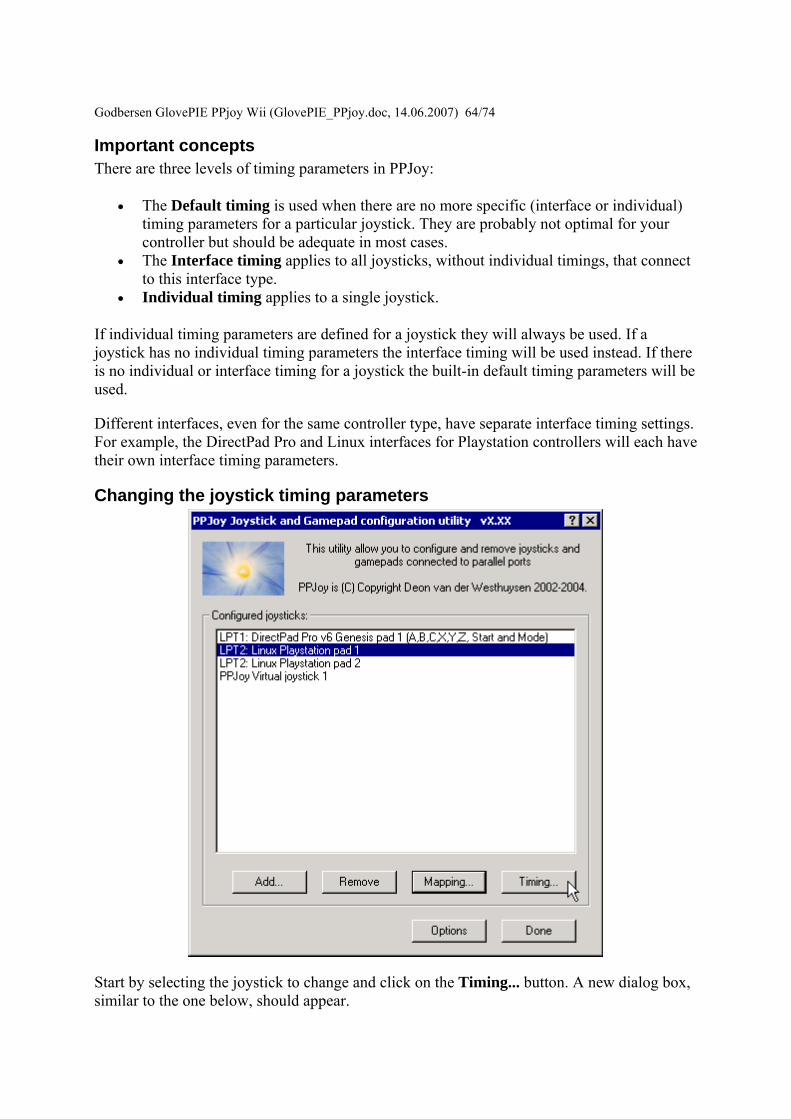
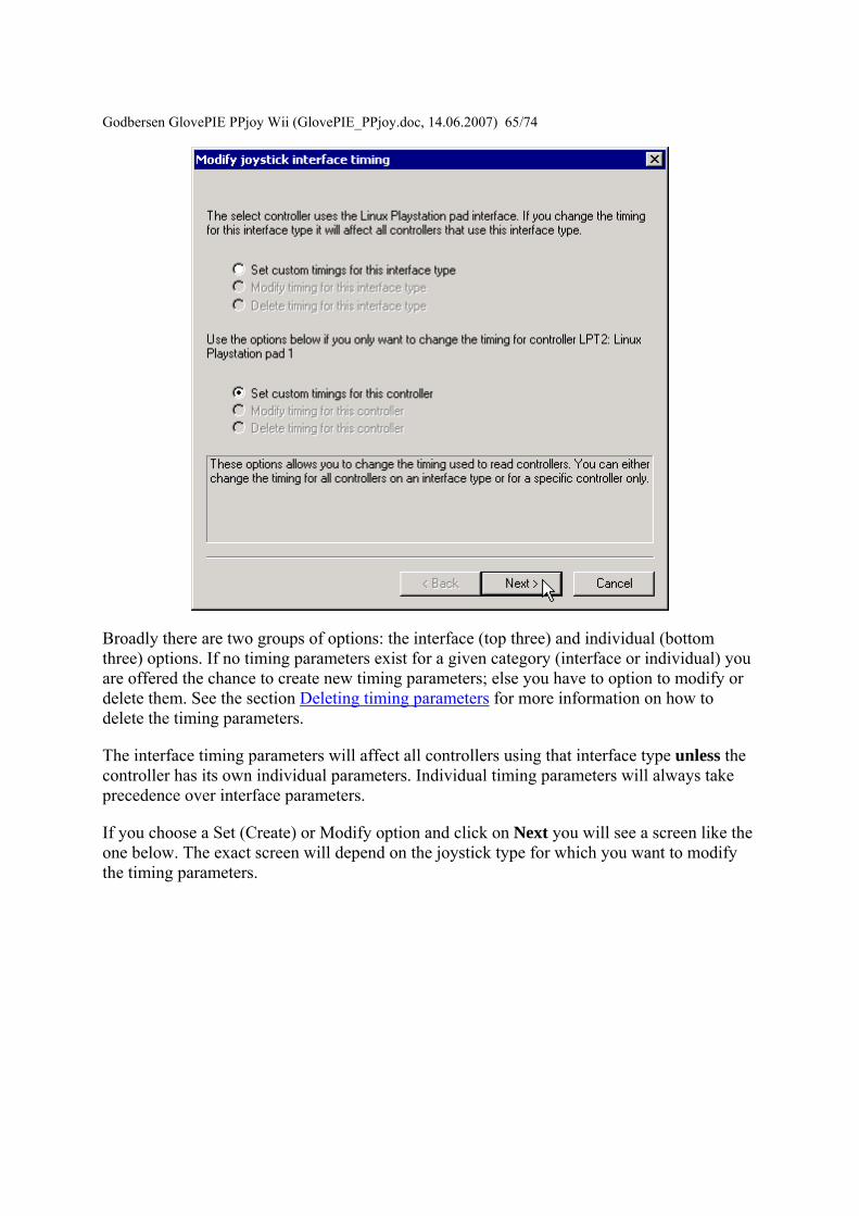
Godbersen Gl
ovePIE PPjoy Wii (GlovePIE_PPjoydoc 14062007) 6574
Broadly there are two groups of options the interface (top three) and individual (bottom three) options If no timing parameters exist for a given category (interface or individual) you are offered the chance to create new timing parameters else you have to option to modify or delete them See the section Deleting timing parameters for more information on how to delete the timing parameters
The interface timing parameters will affect all controllers using that interface type unless the controller has its own individual parameters Individual timing parameters will always take precedence over interface parameters
If you choose a Set (Create) or Modify option and click on Next you will see a screen like the one below The exact screen will depend on the joystick type for which you want to modify the timing parameters
Godbersen Gl
ovePIE PPjoy Wii (GlovePIE_PPjoydoc 14062007) 6674
The top part of the screen will list the timing parameters available for the selected controller or interface and allow you to change them Click on Apply to activate the new parameters while keeping the wizard open Clicking on Finish will apply the new timing values and close the wizard
The best strategy to configure timing parameters is probably to gradually lower and apply one parameter until the controllers operation becomes unstable Repeat this process for the other parameters
Clicking on Reset defaults will change the timing parameters back to the values they were when the wizard was started and apply them
Click on Finish after modifying the timing parameters
Godbersen Glov
ePIE PPjoy Wii (GlovePIE_PPjoydoc 14062007) 6774
Deleting timing parameters
Start by selecting a joystick and clicking on the Timing button
Godbersen Gl
ovePIE PPjoy Wii (GlovePIE_PPjoydoc 14062007) 6874
Select whether you want to delete the individual timing parameters for a joystick or the interface timing parameters Then click on Next If timing parameters do not exist the option to delete it will be greyed out
Godbersen Gl
ovePIE PPjoy Wii (GlovePIE_PPjoydoc 14062007) 6974
This is the confirmation screen before the delete You have to select Yes before the Finish button will be activated After you selected Yes click on Finish
Introduction This page provides information on the timing parameters available to tune the way PPJoy scans various controller types
The following controller types have customisable timing parameters
bull Sega Genesis controllers bull LPT-switch controllers bull PPM RC transmitters bull Playstation controllers bull SNESNES controllers
Sega Genesis controller timing parameters The timing parameters presented below are applicable to all Genesys interfaces
Godb
ersen GlovePIE PPjoy Wii (GlovePIE_PPjoydoc 14062007) 7074
There are two protocols used to Sega Genesis controllers The protocol used depends on the controller subtype specified when the controller was added If you specify ABC and Start as the controller type the 3-button protocol will be used if you specify ABCXYZ Start and Mode the 6-button protocol is used
bull Genesis interbit delay specifies the number of microseconds delay between changing the state of the Select line and reading the joystick state when using the 3-button protocol
bull Genesis 6 button interbit delay specifies the number of microseconds delay between changing the state of the Select line and reading the joystick state when using the 6-button protocol
LPT-switch controller timing parameters The timing parameters presented below are applicable to the LPT-switch interface
Godbersen Glov
ePIE PPjoy Wii (GlovePIE_PPjoydoc 14062007) 7174
The LPTswitch interface has a single timing parameter LPTswitch row select delay This parameter specifies the delay in microseconds between setting the row-select line low and reading the column data from the interface
PPM RC transmitter timing parameters The timing parameters presented below are applicable to the PPM RC transmitter interface
The PPM RC IRQ interface measures the durations between two consecutive low-to-high transitions of the IRQ pin This means that PPJoy does not care whether the timing pulses are high or low (Normal or Inverted signal)
The three applicable timing parameters are
bull PPM min servo pulse width specifies the minimum duration in microseconds between timing pulses If the duration between two consecutive pulses is less than this value the corresponding joystick axis will report its minimum position
bull PPM max servo pulse width specifies the maximum duration in microseconds between timing pulses If the duration between two consecutive pulses is more than this value but less than the minimum sync pulse width the corresponding joystick axis will report its maximum position
Godbersen GlovePIE PPjoy Wii (GlovePIE_PPjoydoc 14062007) 7274
bull PPM min sync pulse width specifies the minimum duration in microseconds of the sync pulse An inter-pulse duration greater than this value marks the beginning of a new frame
Playstation timing parameters The timing parameters presented below are applicable to Playstation interfaces
The figure above is timing for the transfer of an entire data packet The diagram below details the transfer of a single byte between the PC and PSX controller
There are five parameters for Playstation controllers
bull PSX Sel delay specifies the duration in microseconds that the select signal will be taken low before the first byte is transferred
bull PSX Bit delay specifies the duration in microseconds the delay between setting the clock signal high and writing a bit to the controller and between setting the clock line low and reading a bit from the controller
bull PSX Ack1 delay specifies the maximum duration in microseconds to wait for an ACK pulse from the controller after transferring the first byte to the controller
bull PSX AckX delay specifies the maximum duration in microseconds to wait for an ACK pulse from the controller after transferring the second or later byte to the controller
bull PSX Tail delay specifies the duration in microseconds that the Select signal will remain low after the packet transfer between the PC and controller is completed
Godb
ersen GlovePIE PPjoy Wii (GlovePIE_PPjoydoc 14062007) 7374
SNESNES timing parameters The timing parameters presented below are applicable to all SNESNESVirtual Gameboy interfaces
SNESNES interfaces have two timing parameters
bull SNES setup delay specifies the duration in microseconds that the latch signal will be held high
bull SNES interbit delay specifies the duration in microseconds between changes in the signal Every two bit delays an input bit will be read from the controller
Setting PPJoy global options PPJoy has a number of global options that affects the operation of one or more interfaces The options screen shown below can be activated by clicking on the Options button in the main PPJoy screen
Currently PPJoy supports the following options
bull Debug PPM RC interface Setting this option causes PPJoy to make a click (toggle speaker state) every time it detects an incoming pulse from PPM interface (LPT IRQ triggered) When the interface is working properly you should hear a steady tone
Godbersen GlovePIE PPjoy Wii (GlovePIE_PPjoydoc 14062007) 7474
bull Debug Playstation interfaces Setting this option causes PPJoy to make a click each time it reads an invalidcorrupted data packet from a playstation controller
bull Dont allocate ports to assigned joysticks This option only affects PPJoy on Windows 2000 XP and 2003 When it is set PPJoy acts the same way is does on Windows 98 Me where it does not allocate a parallel port when a joystick is configured Thus you do not have to disable PPJoy to use a printer connected to the parallel port
It is recommended that you do not turn on this option Turning on this option may interfere with printing and will also disable the PPM RC interface You need to restart your computer for changes to this option to take effect
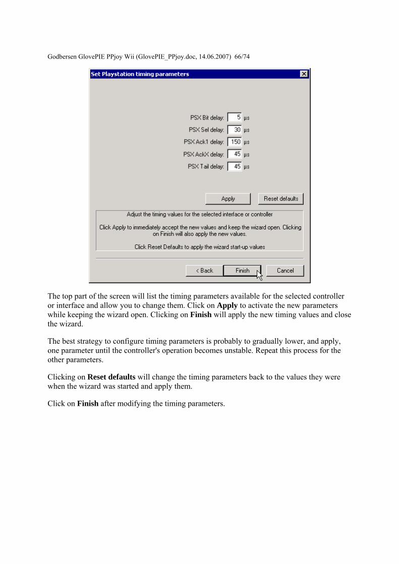
Godbersen Gl
ovePIE PPjoy Wii (GlovePIE_PPjoydoc 14062007) 6674
The top part of the screen will list the timing parameters available for the selected controller or interface and allow you to change them Click on Apply to activate the new parameters while keeping the wizard open Clicking on Finish will apply the new timing values and close the wizard
The best strategy to configure timing parameters is probably to gradually lower and apply one parameter until the controllers operation becomes unstable Repeat this process for the other parameters
Clicking on Reset defaults will change the timing parameters back to the values they were when the wizard was started and apply them
Click on Finish after modifying the timing parameters
Godbersen Glov
ePIE PPjoy Wii (GlovePIE_PPjoydoc 14062007) 6774
Deleting timing parameters
Start by selecting a joystick and clicking on the Timing button
Godbersen Gl
ovePIE PPjoy Wii (GlovePIE_PPjoydoc 14062007) 6874
Select whether you want to delete the individual timing parameters for a joystick or the interface timing parameters Then click on Next If timing parameters do not exist the option to delete it will be greyed out
Godbersen Gl
ovePIE PPjoy Wii (GlovePIE_PPjoydoc 14062007) 6974
This is the confirmation screen before the delete You have to select Yes before the Finish button will be activated After you selected Yes click on Finish
Introduction This page provides information on the timing parameters available to tune the way PPJoy scans various controller types
The following controller types have customisable timing parameters
bull Sega Genesis controllers bull LPT-switch controllers bull PPM RC transmitters bull Playstation controllers bull SNESNES controllers
Sega Genesis controller timing parameters The timing parameters presented below are applicable to all Genesys interfaces
Godb
ersen GlovePIE PPjoy Wii (GlovePIE_PPjoydoc 14062007) 7074
There are two protocols used to Sega Genesis controllers The protocol used depends on the controller subtype specified when the controller was added If you specify ABC and Start as the controller type the 3-button protocol will be used if you specify ABCXYZ Start and Mode the 6-button protocol is used
bull Genesis interbit delay specifies the number of microseconds delay between changing the state of the Select line and reading the joystick state when using the 3-button protocol
bull Genesis 6 button interbit delay specifies the number of microseconds delay between changing the state of the Select line and reading the joystick state when using the 6-button protocol
LPT-switch controller timing parameters The timing parameters presented below are applicable to the LPT-switch interface
Godbersen Glov
ePIE PPjoy Wii (GlovePIE_PPjoydoc 14062007) 7174
The LPTswitch interface has a single timing parameter LPTswitch row select delay This parameter specifies the delay in microseconds between setting the row-select line low and reading the column data from the interface
PPM RC transmitter timing parameters The timing parameters presented below are applicable to the PPM RC transmitter interface
The PPM RC IRQ interface measures the durations between two consecutive low-to-high transitions of the IRQ pin This means that PPJoy does not care whether the timing pulses are high or low (Normal or Inverted signal)
The three applicable timing parameters are
bull PPM min servo pulse width specifies the minimum duration in microseconds between timing pulses If the duration between two consecutive pulses is less than this value the corresponding joystick axis will report its minimum position
bull PPM max servo pulse width specifies the maximum duration in microseconds between timing pulses If the duration between two consecutive pulses is more than this value but less than the minimum sync pulse width the corresponding joystick axis will report its maximum position
Godbersen GlovePIE PPjoy Wii (GlovePIE_PPjoydoc 14062007) 7274
bull PPM min sync pulse width specifies the minimum duration in microseconds of the sync pulse An inter-pulse duration greater than this value marks the beginning of a new frame
Playstation timing parameters The timing parameters presented below are applicable to Playstation interfaces
The figure above is timing for the transfer of an entire data packet The diagram below details the transfer of a single byte between the PC and PSX controller
There are five parameters for Playstation controllers
bull PSX Sel delay specifies the duration in microseconds that the select signal will be taken low before the first byte is transferred
bull PSX Bit delay specifies the duration in microseconds the delay between setting the clock signal high and writing a bit to the controller and between setting the clock line low and reading a bit from the controller
bull PSX Ack1 delay specifies the maximum duration in microseconds to wait for an ACK pulse from the controller after transferring the first byte to the controller
bull PSX AckX delay specifies the maximum duration in microseconds to wait for an ACK pulse from the controller after transferring the second or later byte to the controller
bull PSX Tail delay specifies the duration in microseconds that the Select signal will remain low after the packet transfer between the PC and controller is completed
Godb
ersen GlovePIE PPjoy Wii (GlovePIE_PPjoydoc 14062007) 7374
SNESNES timing parameters The timing parameters presented below are applicable to all SNESNESVirtual Gameboy interfaces
SNESNES interfaces have two timing parameters
bull SNES setup delay specifies the duration in microseconds that the latch signal will be held high
bull SNES interbit delay specifies the duration in microseconds between changes in the signal Every two bit delays an input bit will be read from the controller
Setting PPJoy global options PPJoy has a number of global options that affects the operation of one or more interfaces The options screen shown below can be activated by clicking on the Options button in the main PPJoy screen
Currently PPJoy supports the following options
bull Debug PPM RC interface Setting this option causes PPJoy to make a click (toggle speaker state) every time it detects an incoming pulse from PPM interface (LPT IRQ triggered) When the interface is working properly you should hear a steady tone
Godbersen GlovePIE PPjoy Wii (GlovePIE_PPjoydoc 14062007) 7474
bull Debug Playstation interfaces Setting this option causes PPJoy to make a click each time it reads an invalidcorrupted data packet from a playstation controller
bull Dont allocate ports to assigned joysticks This option only affects PPJoy on Windows 2000 XP and 2003 When it is set PPJoy acts the same way is does on Windows 98 Me where it does not allocate a parallel port when a joystick is configured Thus you do not have to disable PPJoy to use a printer connected to the parallel port
It is recommended that you do not turn on this option Turning on this option may interfere with printing and will also disable the PPM RC interface You need to restart your computer for changes to this option to take effect
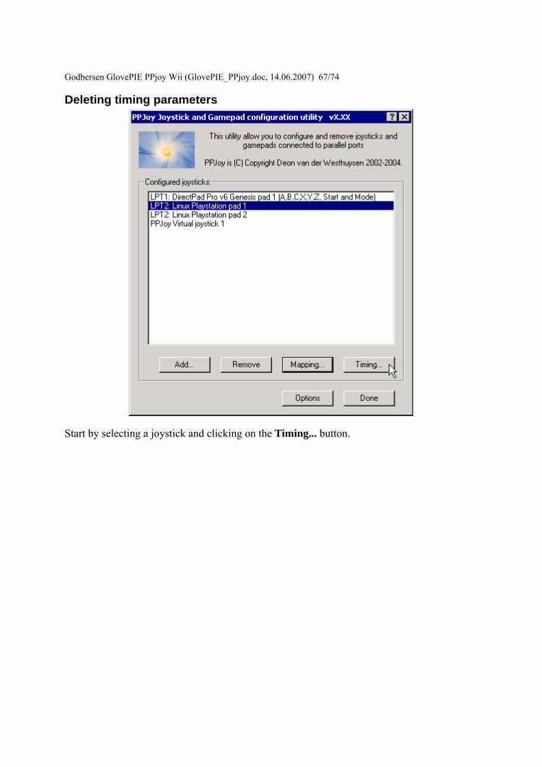
Godbersen Glov
ePIE PPjoy Wii (GlovePIE_PPjoydoc 14062007) 6774
Deleting timing parameters
Start by selecting a joystick and clicking on the Timing button
Godbersen Gl
ovePIE PPjoy Wii (GlovePIE_PPjoydoc 14062007) 6874
Select whether you want to delete the individual timing parameters for a joystick or the interface timing parameters Then click on Next If timing parameters do not exist the option to delete it will be greyed out
Godbersen Gl
ovePIE PPjoy Wii (GlovePIE_PPjoydoc 14062007) 6974
This is the confirmation screen before the delete You have to select Yes before the Finish button will be activated After you selected Yes click on Finish
Introduction This page provides information on the timing parameters available to tune the way PPJoy scans various controller types
The following controller types have customisable timing parameters
bull Sega Genesis controllers bull LPT-switch controllers bull PPM RC transmitters bull Playstation controllers bull SNESNES controllers
Sega Genesis controller timing parameters The timing parameters presented below are applicable to all Genesys interfaces
Godb
ersen GlovePIE PPjoy Wii (GlovePIE_PPjoydoc 14062007) 7074
There are two protocols used to Sega Genesis controllers The protocol used depends on the controller subtype specified when the controller was added If you specify ABC and Start as the controller type the 3-button protocol will be used if you specify ABCXYZ Start and Mode the 6-button protocol is used
bull Genesis interbit delay specifies the number of microseconds delay between changing the state of the Select line and reading the joystick state when using the 3-button protocol
bull Genesis 6 button interbit delay specifies the number of microseconds delay between changing the state of the Select line and reading the joystick state when using the 6-button protocol
LPT-switch controller timing parameters The timing parameters presented below are applicable to the LPT-switch interface
Godbersen Glov
ePIE PPjoy Wii (GlovePIE_PPjoydoc 14062007) 7174
The LPTswitch interface has a single timing parameter LPTswitch row select delay This parameter specifies the delay in microseconds between setting the row-select line low and reading the column data from the interface
PPM RC transmitter timing parameters The timing parameters presented below are applicable to the PPM RC transmitter interface
The PPM RC IRQ interface measures the durations between two consecutive low-to-high transitions of the IRQ pin This means that PPJoy does not care whether the timing pulses are high or low (Normal or Inverted signal)
The three applicable timing parameters are
bull PPM min servo pulse width specifies the minimum duration in microseconds between timing pulses If the duration between two consecutive pulses is less than this value the corresponding joystick axis will report its minimum position
bull PPM max servo pulse width specifies the maximum duration in microseconds between timing pulses If the duration between two consecutive pulses is more than this value but less than the minimum sync pulse width the corresponding joystick axis will report its maximum position
Godbersen GlovePIE PPjoy Wii (GlovePIE_PPjoydoc 14062007) 7274
bull PPM min sync pulse width specifies the minimum duration in microseconds of the sync pulse An inter-pulse duration greater than this value marks the beginning of a new frame
Playstation timing parameters The timing parameters presented below are applicable to Playstation interfaces
The figure above is timing for the transfer of an entire data packet The diagram below details the transfer of a single byte between the PC and PSX controller
There are five parameters for Playstation controllers
bull PSX Sel delay specifies the duration in microseconds that the select signal will be taken low before the first byte is transferred
bull PSX Bit delay specifies the duration in microseconds the delay between setting the clock signal high and writing a bit to the controller and between setting the clock line low and reading a bit from the controller
bull PSX Ack1 delay specifies the maximum duration in microseconds to wait for an ACK pulse from the controller after transferring the first byte to the controller
bull PSX AckX delay specifies the maximum duration in microseconds to wait for an ACK pulse from the controller after transferring the second or later byte to the controller
bull PSX Tail delay specifies the duration in microseconds that the Select signal will remain low after the packet transfer between the PC and controller is completed
Godb
ersen GlovePIE PPjoy Wii (GlovePIE_PPjoydoc 14062007) 7374
SNESNES timing parameters The timing parameters presented below are applicable to all SNESNESVirtual Gameboy interfaces
SNESNES interfaces have two timing parameters
bull SNES setup delay specifies the duration in microseconds that the latch signal will be held high
bull SNES interbit delay specifies the duration in microseconds between changes in the signal Every two bit delays an input bit will be read from the controller
Setting PPJoy global options PPJoy has a number of global options that affects the operation of one or more interfaces The options screen shown below can be activated by clicking on the Options button in the main PPJoy screen
Currently PPJoy supports the following options
bull Debug PPM RC interface Setting this option causes PPJoy to make a click (toggle speaker state) every time it detects an incoming pulse from PPM interface (LPT IRQ triggered) When the interface is working properly you should hear a steady tone
Godbersen GlovePIE PPjoy Wii (GlovePIE_PPjoydoc 14062007) 7474
bull Debug Playstation interfaces Setting this option causes PPJoy to make a click each time it reads an invalidcorrupted data packet from a playstation controller
bull Dont allocate ports to assigned joysticks This option only affects PPJoy on Windows 2000 XP and 2003 When it is set PPJoy acts the same way is does on Windows 98 Me where it does not allocate a parallel port when a joystick is configured Thus you do not have to disable PPJoy to use a printer connected to the parallel port
It is recommended that you do not turn on this option Turning on this option may interfere with printing and will also disable the PPM RC interface You need to restart your computer for changes to this option to take effect
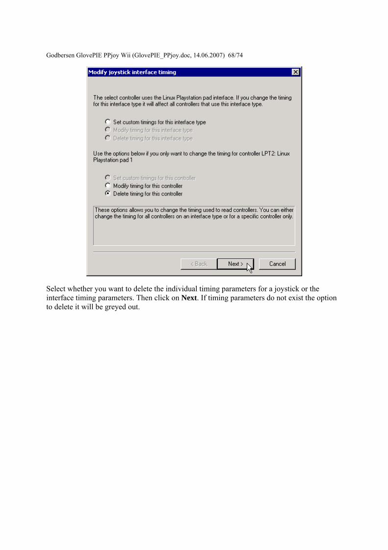
Godbersen Gl
ovePIE PPjoy Wii (GlovePIE_PPjoydoc 14062007) 6874
Select whether you want to delete the individual timing parameters for a joystick or the interface timing parameters Then click on Next If timing parameters do not exist the option to delete it will be greyed out
Godbersen Gl
ovePIE PPjoy Wii (GlovePIE_PPjoydoc 14062007) 6974
This is the confirmation screen before the delete You have to select Yes before the Finish button will be activated After you selected Yes click on Finish
Introduction This page provides information on the timing parameters available to tune the way PPJoy scans various controller types
The following controller types have customisable timing parameters
bull Sega Genesis controllers bull LPT-switch controllers bull PPM RC transmitters bull Playstation controllers bull SNESNES controllers
Sega Genesis controller timing parameters The timing parameters presented below are applicable to all Genesys interfaces
Godb
ersen GlovePIE PPjoy Wii (GlovePIE_PPjoydoc 14062007) 7074
There are two protocols used to Sega Genesis controllers The protocol used depends on the controller subtype specified when the controller was added If you specify ABC and Start as the controller type the 3-button protocol will be used if you specify ABCXYZ Start and Mode the 6-button protocol is used
bull Genesis interbit delay specifies the number of microseconds delay between changing the state of the Select line and reading the joystick state when using the 3-button protocol
bull Genesis 6 button interbit delay specifies the number of microseconds delay between changing the state of the Select line and reading the joystick state when using the 6-button protocol
LPT-switch controller timing parameters The timing parameters presented below are applicable to the LPT-switch interface
Godbersen Glov
ePIE PPjoy Wii (GlovePIE_PPjoydoc 14062007) 7174
The LPTswitch interface has a single timing parameter LPTswitch row select delay This parameter specifies the delay in microseconds between setting the row-select line low and reading the column data from the interface
PPM RC transmitter timing parameters The timing parameters presented below are applicable to the PPM RC transmitter interface
The PPM RC IRQ interface measures the durations between two consecutive low-to-high transitions of the IRQ pin This means that PPJoy does not care whether the timing pulses are high or low (Normal or Inverted signal)
The three applicable timing parameters are
bull PPM min servo pulse width specifies the minimum duration in microseconds between timing pulses If the duration between two consecutive pulses is less than this value the corresponding joystick axis will report its minimum position
bull PPM max servo pulse width specifies the maximum duration in microseconds between timing pulses If the duration between two consecutive pulses is more than this value but less than the minimum sync pulse width the corresponding joystick axis will report its maximum position
Godbersen GlovePIE PPjoy Wii (GlovePIE_PPjoydoc 14062007) 7274
bull PPM min sync pulse width specifies the minimum duration in microseconds of the sync pulse An inter-pulse duration greater than this value marks the beginning of a new frame
Playstation timing parameters The timing parameters presented below are applicable to Playstation interfaces
The figure above is timing for the transfer of an entire data packet The diagram below details the transfer of a single byte between the PC and PSX controller
There are five parameters for Playstation controllers
bull PSX Sel delay specifies the duration in microseconds that the select signal will be taken low before the first byte is transferred
bull PSX Bit delay specifies the duration in microseconds the delay between setting the clock signal high and writing a bit to the controller and between setting the clock line low and reading a bit from the controller
bull PSX Ack1 delay specifies the maximum duration in microseconds to wait for an ACK pulse from the controller after transferring the first byte to the controller
bull PSX AckX delay specifies the maximum duration in microseconds to wait for an ACK pulse from the controller after transferring the second or later byte to the controller
bull PSX Tail delay specifies the duration in microseconds that the Select signal will remain low after the packet transfer between the PC and controller is completed
Godb
ersen GlovePIE PPjoy Wii (GlovePIE_PPjoydoc 14062007) 7374
SNESNES timing parameters The timing parameters presented below are applicable to all SNESNESVirtual Gameboy interfaces
SNESNES interfaces have two timing parameters
bull SNES setup delay specifies the duration in microseconds that the latch signal will be held high
bull SNES interbit delay specifies the duration in microseconds between changes in the signal Every two bit delays an input bit will be read from the controller
Setting PPJoy global options PPJoy has a number of global options that affects the operation of one or more interfaces The options screen shown below can be activated by clicking on the Options button in the main PPJoy screen
Currently PPJoy supports the following options
bull Debug PPM RC interface Setting this option causes PPJoy to make a click (toggle speaker state) every time it detects an incoming pulse from PPM interface (LPT IRQ triggered) When the interface is working properly you should hear a steady tone
Godbersen GlovePIE PPjoy Wii (GlovePIE_PPjoydoc 14062007) 7474
bull Debug Playstation interfaces Setting this option causes PPJoy to make a click each time it reads an invalidcorrupted data packet from a playstation controller
bull Dont allocate ports to assigned joysticks This option only affects PPJoy on Windows 2000 XP and 2003 When it is set PPJoy acts the same way is does on Windows 98 Me where it does not allocate a parallel port when a joystick is configured Thus you do not have to disable PPJoy to use a printer connected to the parallel port
It is recommended that you do not turn on this option Turning on this option may interfere with printing and will also disable the PPM RC interface You need to restart your computer for changes to this option to take effect
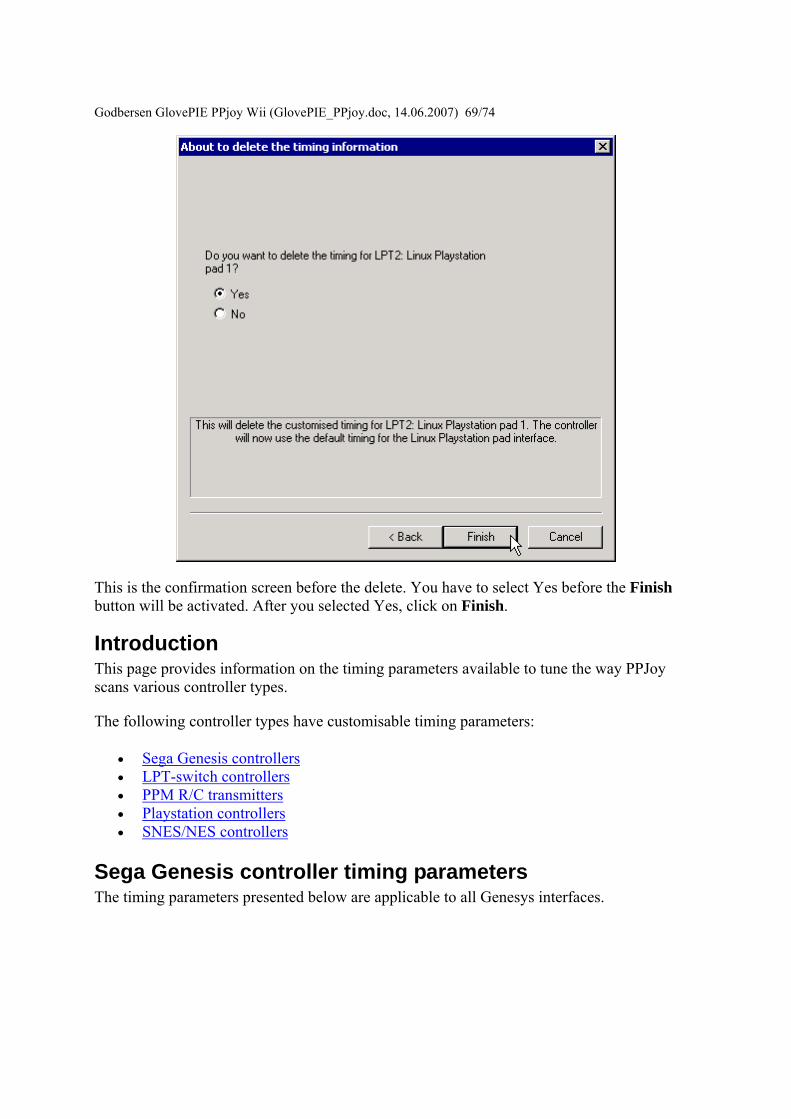
Godbersen Gl
ovePIE PPjoy Wii (GlovePIE_PPjoydoc 14062007) 6974
This is the confirmation screen before the delete You have to select Yes before the Finish button will be activated After you selected Yes click on Finish
Introduction This page provides information on the timing parameters available to tune the way PPJoy scans various controller types
The following controller types have customisable timing parameters
bull Sega Genesis controllers bull LPT-switch controllers bull PPM RC transmitters bull Playstation controllers bull SNESNES controllers
Sega Genesis controller timing parameters The timing parameters presented below are applicable to all Genesys interfaces
Godb
ersen GlovePIE PPjoy Wii (GlovePIE_PPjoydoc 14062007) 7074
There are two protocols used to Sega Genesis controllers The protocol used depends on the controller subtype specified when the controller was added If you specify ABC and Start as the controller type the 3-button protocol will be used if you specify ABCXYZ Start and Mode the 6-button protocol is used
bull Genesis interbit delay specifies the number of microseconds delay between changing the state of the Select line and reading the joystick state when using the 3-button protocol
bull Genesis 6 button interbit delay specifies the number of microseconds delay between changing the state of the Select line and reading the joystick state when using the 6-button protocol
LPT-switch controller timing parameters The timing parameters presented below are applicable to the LPT-switch interface
Godbersen Glov
ePIE PPjoy Wii (GlovePIE_PPjoydoc 14062007) 7174
The LPTswitch interface has a single timing parameter LPTswitch row select delay This parameter specifies the delay in microseconds between setting the row-select line low and reading the column data from the interface
PPM RC transmitter timing parameters The timing parameters presented below are applicable to the PPM RC transmitter interface
The PPM RC IRQ interface measures the durations between two consecutive low-to-high transitions of the IRQ pin This means that PPJoy does not care whether the timing pulses are high or low (Normal or Inverted signal)
The three applicable timing parameters are
bull PPM min servo pulse width specifies the minimum duration in microseconds between timing pulses If the duration between two consecutive pulses is less than this value the corresponding joystick axis will report its minimum position
bull PPM max servo pulse width specifies the maximum duration in microseconds between timing pulses If the duration between two consecutive pulses is more than this value but less than the minimum sync pulse width the corresponding joystick axis will report its maximum position
Godbersen GlovePIE PPjoy Wii (GlovePIE_PPjoydoc 14062007) 7274
bull PPM min sync pulse width specifies the minimum duration in microseconds of the sync pulse An inter-pulse duration greater than this value marks the beginning of a new frame
Playstation timing parameters The timing parameters presented below are applicable to Playstation interfaces
The figure above is timing for the transfer of an entire data packet The diagram below details the transfer of a single byte between the PC and PSX controller
There are five parameters for Playstation controllers
bull PSX Sel delay specifies the duration in microseconds that the select signal will be taken low before the first byte is transferred
bull PSX Bit delay specifies the duration in microseconds the delay between setting the clock signal high and writing a bit to the controller and between setting the clock line low and reading a bit from the controller
bull PSX Ack1 delay specifies the maximum duration in microseconds to wait for an ACK pulse from the controller after transferring the first byte to the controller
bull PSX AckX delay specifies the maximum duration in microseconds to wait for an ACK pulse from the controller after transferring the second or later byte to the controller
bull PSX Tail delay specifies the duration in microseconds that the Select signal will remain low after the packet transfer between the PC and controller is completed
Godb
ersen GlovePIE PPjoy Wii (GlovePIE_PPjoydoc 14062007) 7374
SNESNES timing parameters The timing parameters presented below are applicable to all SNESNESVirtual Gameboy interfaces
SNESNES interfaces have two timing parameters
bull SNES setup delay specifies the duration in microseconds that the latch signal will be held high
bull SNES interbit delay specifies the duration in microseconds between changes in the signal Every two bit delays an input bit will be read from the controller
Setting PPJoy global options PPJoy has a number of global options that affects the operation of one or more interfaces The options screen shown below can be activated by clicking on the Options button in the main PPJoy screen
Currently PPJoy supports the following options
bull Debug PPM RC interface Setting this option causes PPJoy to make a click (toggle speaker state) every time it detects an incoming pulse from PPM interface (LPT IRQ triggered) When the interface is working properly you should hear a steady tone
Godbersen GlovePIE PPjoy Wii (GlovePIE_PPjoydoc 14062007) 7474
bull Debug Playstation interfaces Setting this option causes PPJoy to make a click each time it reads an invalidcorrupted data packet from a playstation controller
bull Dont allocate ports to assigned joysticks This option only affects PPJoy on Windows 2000 XP and 2003 When it is set PPJoy acts the same way is does on Windows 98 Me where it does not allocate a parallel port when a joystick is configured Thus you do not have to disable PPJoy to use a printer connected to the parallel port
It is recommended that you do not turn on this option Turning on this option may interfere with printing and will also disable the PPM RC interface You need to restart your computer for changes to this option to take effect
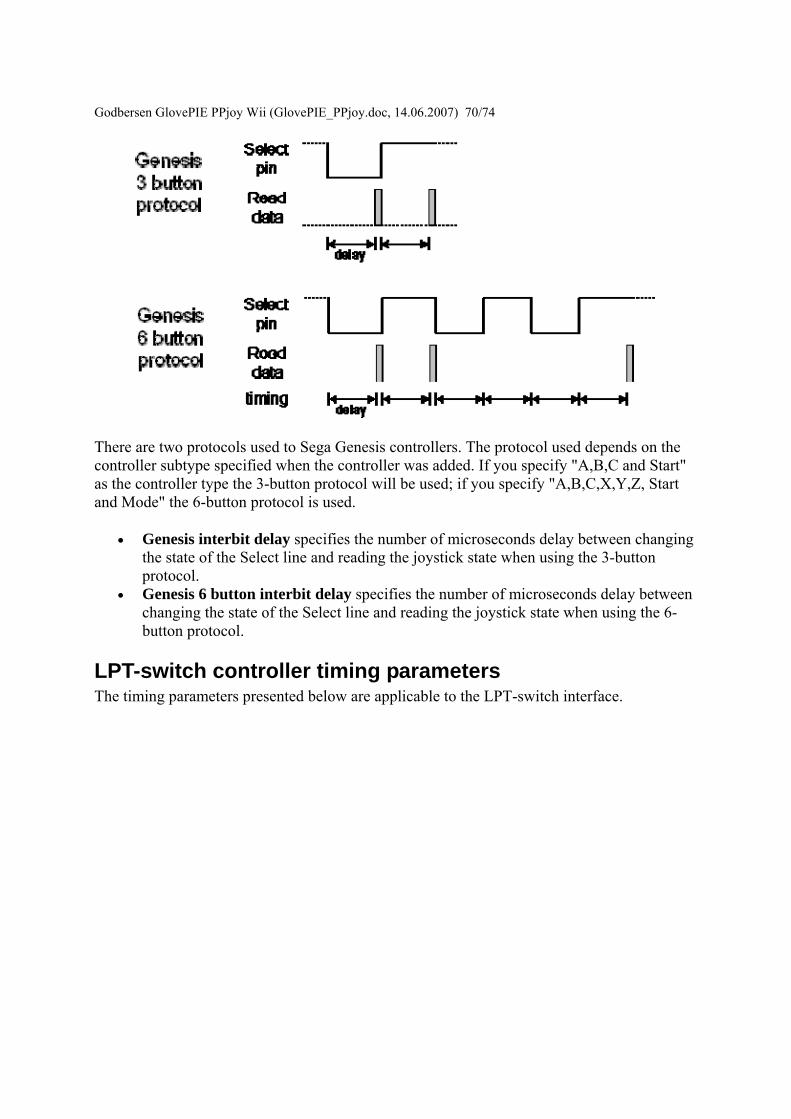
Godb
ersen GlovePIE PPjoy Wii (GlovePIE_PPjoydoc 14062007) 7074
There are two protocols used to Sega Genesis controllers The protocol used depends on the controller subtype specified when the controller was added If you specify ABC and Start as the controller type the 3-button protocol will be used if you specify ABCXYZ Start and Mode the 6-button protocol is used
bull Genesis interbit delay specifies the number of microseconds delay between changing the state of the Select line and reading the joystick state when using the 3-button protocol
bull Genesis 6 button interbit delay specifies the number of microseconds delay between changing the state of the Select line and reading the joystick state when using the 6-button protocol
LPT-switch controller timing parameters The timing parameters presented below are applicable to the LPT-switch interface
Godbersen Glov
ePIE PPjoy Wii (GlovePIE_PPjoydoc 14062007) 7174
The LPTswitch interface has a single timing parameter LPTswitch row select delay This parameter specifies the delay in microseconds between setting the row-select line low and reading the column data from the interface
PPM RC transmitter timing parameters The timing parameters presented below are applicable to the PPM RC transmitter interface
The PPM RC IRQ interface measures the durations between two consecutive low-to-high transitions of the IRQ pin This means that PPJoy does not care whether the timing pulses are high or low (Normal or Inverted signal)
The three applicable timing parameters are
bull PPM min servo pulse width specifies the minimum duration in microseconds between timing pulses If the duration between two consecutive pulses is less than this value the corresponding joystick axis will report its minimum position
bull PPM max servo pulse width specifies the maximum duration in microseconds between timing pulses If the duration between two consecutive pulses is more than this value but less than the minimum sync pulse width the corresponding joystick axis will report its maximum position
Godbersen GlovePIE PPjoy Wii (GlovePIE_PPjoydoc 14062007) 7274
bull PPM min sync pulse width specifies the minimum duration in microseconds of the sync pulse An inter-pulse duration greater than this value marks the beginning of a new frame
Playstation timing parameters The timing parameters presented below are applicable to Playstation interfaces
The figure above is timing for the transfer of an entire data packet The diagram below details the transfer of a single byte between the PC and PSX controller
There are five parameters for Playstation controllers
bull PSX Sel delay specifies the duration in microseconds that the select signal will be taken low before the first byte is transferred
bull PSX Bit delay specifies the duration in microseconds the delay between setting the clock signal high and writing a bit to the controller and between setting the clock line low and reading a bit from the controller
bull PSX Ack1 delay specifies the maximum duration in microseconds to wait for an ACK pulse from the controller after transferring the first byte to the controller
bull PSX AckX delay specifies the maximum duration in microseconds to wait for an ACK pulse from the controller after transferring the second or later byte to the controller
bull PSX Tail delay specifies the duration in microseconds that the Select signal will remain low after the packet transfer between the PC and controller is completed
Godb
ersen GlovePIE PPjoy Wii (GlovePIE_PPjoydoc 14062007) 7374
SNESNES timing parameters The timing parameters presented below are applicable to all SNESNESVirtual Gameboy interfaces
SNESNES interfaces have two timing parameters
bull SNES setup delay specifies the duration in microseconds that the latch signal will be held high
bull SNES interbit delay specifies the duration in microseconds between changes in the signal Every two bit delays an input bit will be read from the controller
Setting PPJoy global options PPJoy has a number of global options that affects the operation of one or more interfaces The options screen shown below can be activated by clicking on the Options button in the main PPJoy screen
Currently PPJoy supports the following options
bull Debug PPM RC interface Setting this option causes PPJoy to make a click (toggle speaker state) every time it detects an incoming pulse from PPM interface (LPT IRQ triggered) When the interface is working properly you should hear a steady tone
Godbersen GlovePIE PPjoy Wii (GlovePIE_PPjoydoc 14062007) 7474
bull Debug Playstation interfaces Setting this option causes PPJoy to make a click each time it reads an invalidcorrupted data packet from a playstation controller
bull Dont allocate ports to assigned joysticks This option only affects PPJoy on Windows 2000 XP and 2003 When it is set PPJoy acts the same way is does on Windows 98 Me where it does not allocate a parallel port when a joystick is configured Thus you do not have to disable PPJoy to use a printer connected to the parallel port
It is recommended that you do not turn on this option Turning on this option may interfere with printing and will also disable the PPM RC interface You need to restart your computer for changes to this option to take effect
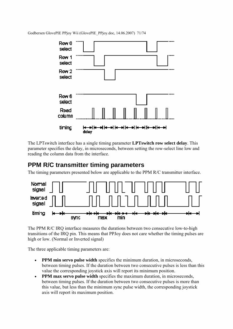
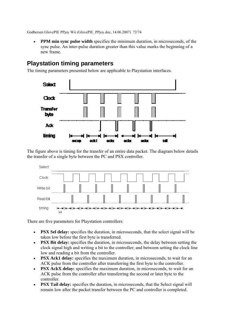
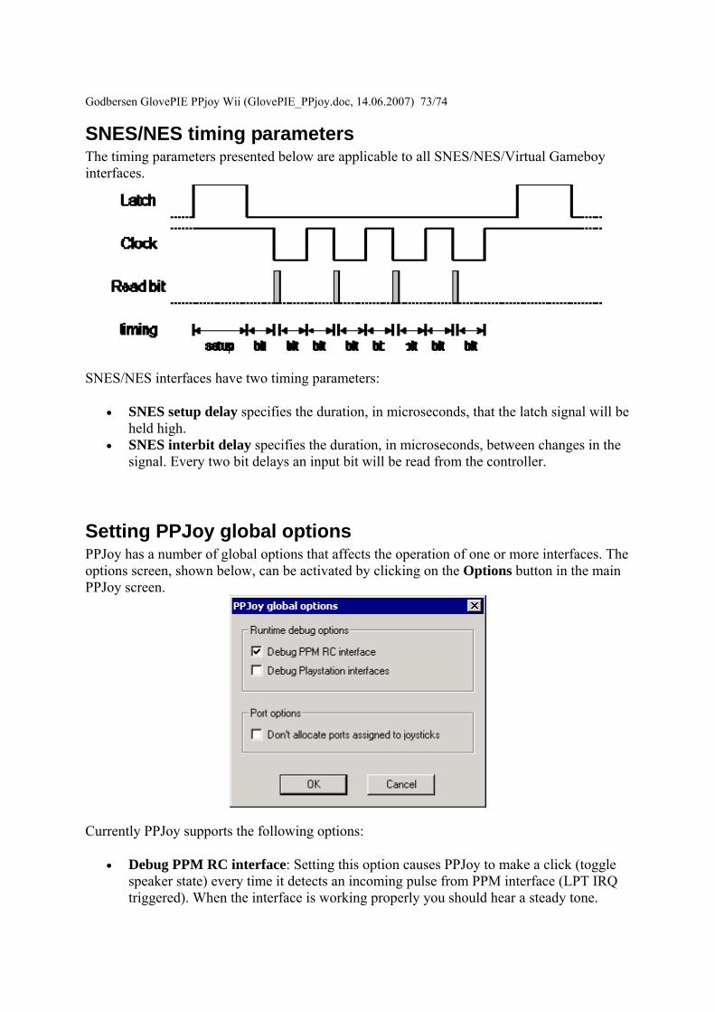