Embed Size (px)
Citation preview

CITY POWER JOHANNESBURG
EVOLUTION OF MEDIUM VOLTAGE
POWER CABLES
PATRICK O’HALLORAN
OCTOBER 2013

Presentation outline
• Introduction to City Power
• MV power cable construction
• Factors influencing cable technology changes (Evolution)
• Cable testing techniques to better determine reliability and remaining life
• Conclusion
Hopefully this presentation evolves your thoughts on MV power cables!

City of Johannesburg: Orientation
& Electricity Supply Rights
Legend
City of Joburg
City Power Supply Area
Eskom Supply Area
South Africa
Johannesburg
BRYANSTON
FERNDALE
ZOLA
LINDEN
FAIRLAND
DUBE
JABAVU
KENSINGTON
HOUGHTON ESTATE
JABULANI
PARKTOWN
GRASMERE
ALEXANDRA
KELVIN
NALEDI
BUCCLEUCH
KIBLER PARK
EDENBURG
MOROKA
TLADI
HORISON
CHIAWELO
ENNERDALE SOUTH
BRUMA
DOBSONVILLE
NANCEFIELD
FLORIDA PARK
MAPETLA
UNAVILLE AH
MAYFAIR
EMDENI
FLORIDA
WYNBERG
FOURWAYS
PARKVIEW
NATURENA
PARKMORE
CRAIGHALL PARK
BEREA
PROTEA NORTH
NEWLANDS
BOSMONT
KLOOFENDAL
SANDHURST
SELBY
DAINFERN
ZONDI
ROBERTSHAM
ATHOLL
MOLAPO
TRIOMF
TURFFONTEIN
CYRILDENE
BRAMLEY
LAWLEY ESTATE
POORTJE
WITPOORTJIE
BERARIO
FINETOWN
MELVILLE
NASREC
NORTHCLIFF
WAVERLEY
WESTCLIFF
MID-ENNERDALE
JEPPESTOWN
OAKDENE
HURLINGHAM
SUIDEROORD
VORNA VALLEY
MOFOLO CENTRAL
OAKLANDS
DISCOVERY
LAWLEY EXT.1
MOLETSANE
ELDORADO PARK
MARLBORO
CRAIGHALL
KLIPSPRUIT
LYNDHURST
LAKESIDE EXT.1
RIVERLEA
LENASIA SOUTH
LENASIA EXT.9
TULISA PARK
FLEURHOF
BASSONIA
LINKSFIELD
BEZUIDENHOUT VALLEY
GREENSIDEROSEBANK
NORWOOD
ROODEPOORT
MARAISBURG
SOUTH HILLS
QUELLERINA
ROSETTENVILLE
WENDYWOOD
DE WETSHOF
LINDHAVEN
NOORDGESIG
GLENESKBOOYSENSMOFOLO NORTH
HELDERKRUIN
ALAN MANOR
MEREDALE
PAULSHOF
INDUSTRIA
CHLOORKOP
KYA SAND
MAYFAIR WEST
DENVER
RABIE RIDGE
PROTEA GLEN
OPHIRTON
SUNNINGHILL
ORANGE FARM
WILROPARK
LENASIA
HAMBERG
EBONY PARK
RIVERCLUB
GREYMONT
KLIPSPRUIT WEST
EMMARENTIA
WOODLANDS
BIRDHAVENRISIDALE
CROWN GARDENS
BLACKHEATH
BELLE-VUE
DEVLAND
RISANA
KILLARNEY
MONTGOMERY PARK
AEROTON
FOREST HILL
LOMBARDY WEST
MALANSHOF
INDUSTRIA WESTBERTRAMS
GALLO MANOR
HORISON PARK
FLORIDA NORTH
MMESI PARK
MEADOWLANDS
MULBARTON
PIMVILLE ZONE 1
LA ROCHELLE
DHLAMINI
RANDPARKRIF
SLOVOVILLE
ELECTRON
CITY AND SUBURBAN
GRESSWOLD
LONE HILL
DOORNFONTEIN
ENNERDALE
COUNTRY VIEW
GILLVIEW
LONE HILL EXT.10
KLIPRIVIERSOOG
VREDEDORP
NOORDWYK
HURST HILL
LYME PARK
KLEVEHILL PARK
RICHMOND
VALERIEDENE
KYALAMI ESTATE
REUVEN
LIEFDE EN VREDE
TANGANANI
DAINFERN RIDGE
AMALGAM
ANCHORVILLE
POWER PARK
TOWNSVIEW
HEADWAY HILL
THETA
HERIOTDALE
KAALFONTEIN EXT.1
MORET
BERGBRON
KELLAND
CONSTANTIA KLOOF
SUNDOWNER
WILGEHEUWEL
EPSOM DOWNS
CRESTA
FOUNDERS HILL
EASTGATE
COMPTONVILLE
ROODEKRANS
FAR EAST BANK
FRANKENWALD
DAVIDSONVILLE
JOHANNESBURG-NORTH
LENASIA EXT.4
CITY DEEP
WOLHUTER
OSUMMIT
JACANLEE
STRETFORD EXT.3
CLEVELAND
Soweto
BENROSE
WITKOPPEN
DALECROSS
HONEYDEW
ARMADALE
NOORDHANG
ZANDSPRUIT EXT.10
FAIRWAY
SHARONLEA
GLEN ATHOL
BOSKRUIN
SOUTHGATE
ROSEACRE
ZAKARIYYA PARK EXT.5
SOUTHFORK
LENASIA SOUTH EXT.20
MAROELADAL EXT.11
MAGALIESSIG
STORMILL
LENASIA SOUTH EXT.6
BARBEQUE DOWNS
RANDJESFONTEIN
MEADOWHURST
BRYANBRINK
STRIJDOMPARK
RAND LEASES EXT.1
MARYVALE
WESTBURY
GLENSAN
ILLOVO
MOODIE HILL
PRINCESS
BRAAMPARK
WILFORDON
TRES JOLIE .
KHYBER ROCK
COMMERCIA
CRAMERVIEW
RANDJESPARK EXT.1
LENASIA EXT.12
BELLAIRSPARK
WILLAWAY
HOOGLAND
HALFWAY HOUSE
PROLECON
NORTHGATE
BATAVIA
EAGLES NEST
RUIMSIG
WATERVAL EXT.2
PRESIDENT PARK
STRATHAVON
PROTEA INDUSTRIAL PARK
MIDRIDGE PARK
DRIEZIEK
FOUNDERS HILL
SEBENZA EXT.6
BORDEAUX
NEWTOWN
FORDSBURG
Reuven
Lenasia
Roodepoort
Randburg
HurstHillSiemert
Edenvale
Midrand
Alexandra
Midrand
7304 km of MV power cable
Installed in City Power
More than 6000 failures in 3 years

Our business model
National Energy Regulator of South Africa (NERSA)Kelvin
We are in the business of buying electricity and selling it to customers
GenerationTransmission Distribution
4

City Power’s Vision
A World Class
Electricity Utility5

Slide 6
Typical example of MV
power cable network
Mini-subs
N/O point
Metal-clad
switchgear
MV LPU
supply
Primary feeders
Secondary feeders
Sub-ring feeder
Sub-switching
stations
Switching stationHV/MV sub-station
MV LPU
supply
Sub-switching
station
Sub-switching
station
N/O points
Secondary
distribution
network

Evolution of MV Power Cables
Evolution, what
should be use?

Slide 8
Evolution of MV Power Cables
• The first power distribution system was developed byThomas Edison in the early 1880’s in New York City.
• A power cable constructed from copper rods, wrapped injute and placed in rigid pipes filled with a bituminouscompound.

Slide 9
Evolution of MV Power Cables
• The range of voltage and the capacity of power transmittedthrough cables are showing a steady increase over the years.
• Environmental concerns, aesthetic issues, lack of servitudesand difficulty in routing overhead lines in urban areas are someof the reasons for the growth of cable technology.
• Due to physical limits on cable lengths for manufacturing andpackaging, joints in cables become inevitable, particularly inthe context of the utility sector.
• Various types of switchgear exist and hence many differentways of terminating need to be considered and understood.
• Loss of skills to install cable systems, especially joints andterminations.

Slide 10
MV power cable
specifications in SA
• SANS 97 - Electric cables –Impregnated-paper-insulated metal-sheathed cables for rated voltages 3,3/3,3 kV up to 19/33 kV
• SANS 1339 - Electric cables –Cross-linked polyethylene (XLPE)-insulated cables for voltages from 3,8/6,6 kV to 19/33 kV
• VC 8077 - Compulsory specification for the safety of medium voltage electric cables
• NRS 013 – Medium-voltage cables

Slide 11
MV Power cable construction
Paper-insulated cables (PILC)
Armoured Unarmoured

Slide 12
• The paper insulation is impregnated with a non-draining compound. Mass Impregnated Non-Draining (MIND) cable mass impregnated using a “non-draining” compound.
Older mass impregnated cables were “draining” and used oil-based compounds susceptible to draining (e.g. rosin oil)
• There are two types of “non-draining” compounds used by various manufacturers :
• a compound processed from a mineral based amorphous crystalline wax.
• more recently a synthetic compound better known as Poly-Iso-Butylene (PIB) compound.
MV Power cable construction
Paper-insulated cables (PILC)

Slide 13
PILC Cable – Belted design
PILC Cable – Screened design (Improved design)
MV Power cable construction
Paper-insulated cables (PILC)

Slide 15
• Electric field lines in belted and individually screened three core cables
Unscreened (belted) cable Screened cable
MV Power cable construction
Paper-insulated cables (PILC)

Slide 16
PILC Belted cable – for “earthed” system design (6,35/11 kV)
PILC Belted cable – for “unearthed” system design (11/11 kV)
MV Power cable construction
Paper-insulated cables (PILC)
Slide 17
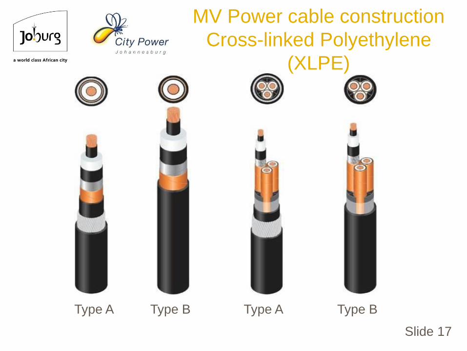
Type A Type B Type A Type B
MV Power cable construction
Cross-linked Polyethylene
(XLPE)
Slide 19
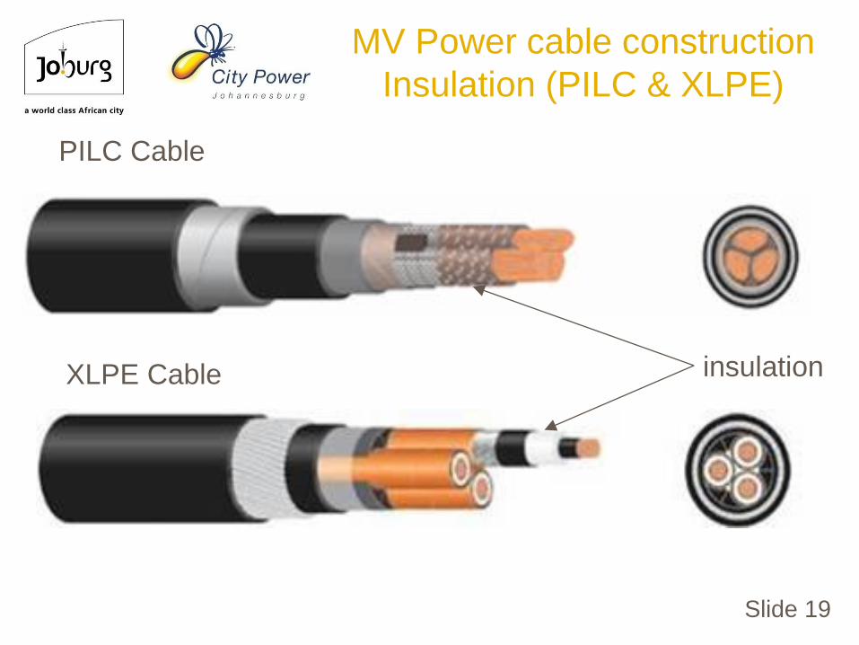
PILC Cable
XLPE Cable insulation
MV Power cable construction
Insulation (PILC & XLPE)

Slide 21
Cable VoltageInsulation Thickness
(SANS 97)
Screened Belted
Core Belt
3,8/6,6 kV N/A 2,1 mm 0,9 mm
6,6/6,6 kV N/A 2,1 mm 2,1 mm
6,35/11 kV 3,2 mm 2,9 mm 0,9 mm
11/11 kV N/A 2,9 mm 2,9 mm
12,7/22 kV 5,8 mm N/A N/A
19/33 kV 7,1 mm N/A N/A
Typical paper insulation thicknesses – SANS 97
MV Power cable construction
Insulation (PILC)

Slide 24
• The polymer chains then combine
• Chains that where “ loose” before are now bound together
• CROSS-LINKED polymers
H2
CC
CC
CH
H H
HH
H
H
H
HR R
C CC C
C
HH
HH
H
HH
HH
RR
MV Power cable construction
Insulation (XLPE)

Slide 26
Typical XLPE insulation thicknesses – SANS 1339 and these are the same as IEC 60502-2
Cable VoltageInsulation Thickness
(SANS 1339, IEC 60502)
3,8/6,6 kV ≥ 2,5 mm
6.35/11 kV 3,4 mm
12,7/22 kV 5,5 mm
19/33 kV 8,0 mm
MV Power cable construction
Insulation (XLPE)

Slide 27
PILC Cable XLPE-insulated Cable
Continuous operating temperature = 70°C Continuous operating temperature = 90°C
Short circuit temperature = 160 °C Short circuit temperature = 250 °C
MV Power cable construction
Insulation operating temperatures

Slide 29
PILC Cable
XLPE Cable core screening
MV Power cable construction
Core (insulation) screening

Slide 33
Strippable core screen (normal design)
Fully bonded core screen
MV Power cable construction
Core (insulation) screening
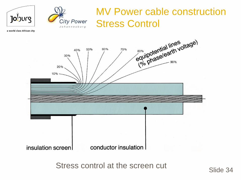
Slide 34Stress control at the screen cut
MV Power cable construction
Stress Control

Slide 35
Stress control is required
at the screen cut
MV Power cable construction
Stress Control

Slide 38
•City Power and Eskom have changed their MV power cablespecifications to longitudinally water blocked XLPE insulatedcables as a standard.
•Concept is like a babies nappy, where water swellablecompounds and tapes are included in the areas where watercould flow in the cable once it has entered in the cable forwhich ever reason. (Damage Sheath, lugs, existing cables,storage, etc.
•Water penetration type test as per SANS 1339 shall beconducted to prove the design.
•This design will extend the life of the cable as when waterenters, it is stopped where it enters. In so doing also stoppingthe old problem of XLPE cables becoming water pipes.
MV Power cable construction
Longitudinally water blocked

Slide 39
MV Power cable construction
Longitudinally water blocked
Areas that have to be water blocked;
Conductors
Core(s) and metallic screening
Laid up cores for 3 core designs
Armouring
Pictures provided by
CBi Electric

MV Power cable construction
Longitudinally water blocked
Slide 40

CBi’s unique
water blocking
tissue tape
filler design
MV Power cable construction
Longitudinally water blocked
Slide 41

All layers removed till
water blocked conductors
for type testing
Test Rig for water
penetration test
MV Power cable construction
Longitudinally water blocked
Water penetration type test as per SANS 1339
Slide 42

MV Power cable construction
Longitudinally water blocked
Water penetration type test as per SANS 1339
Slide 43

Slide 44
0%
20%
40%
60%
80%
100%
PILC XLPE
Terminations
Joints
Cable Insulation
Partial discharge (PD) measured in MV cable systems
(International Statistics)
MV Power cable construction
PD in MV cables systems

Slide 45
Common consequence of failures :
• Loss of supply – cost of unserved energy to customers
• Decreased network reliability:
• network performance
• quality of supply (NRS 048)
• Cost of repairs (cable joints and terminations)
• Typical time of failure – never at a convenient time
• Electrical and mechanical stress on system due to faults
MV Power cable construction
Consequences of failure

Slide 46
Cables and joints:
• Alternative sources of supply (back-feeding) options not always available (e.g. with radials / spurs)
• Requires network switching to isolate faulty section (network reconfiguration to restore supply)
• Emergency way-leaves required for breakdowns
• Excavations cause disruptions to traffic flow
• public inconvenience
• drain on resources !
MV Power cable construction
Consequences of failure

Slide 47
Terminations :
• Termination failure often results in catastrophic damage to equipment:
• followed by equipment failure
• additional costs to replace equipment
• degree of damage dependant on effectiveness of protection systems
• common mode failures result when fault spreads to adjacent switchgear panel compartments (ionisation of air)
• Safety risk to staff and general public from internal arc
MV Power cable construction
Consequences of failure

MV Power cable construction
Consequences of failure
Slide 48

Slide 49
Impregnated paper-insulated cables inherently contain
microvoids but these are generally not serious as the insulation is
considered to be “self-healing”.
Localised discharges melt the impregnating compound locally
resulting in the quenching and healing of the partial discharge site
Moisture is another destructive factor if present in insulation.
The paper used in paper-insulated cables is known to be
hydroscopic (i.e. absorbs water)
• water is removed during manufacturing, and
• prior to jointing and termination (Crackle test)
!!TEST FOR MOISTURE ALWAYS!!
MV Power cable construction
Destructive factors PILC

Slide 50
Poorly manufactured XLPE-insulated cables may also contain
microvoids that, depending on their size, may be detrimental to
the cable life :
• after the discharge is extinguished, the voltage across the
void increases again and a new discharge will ignite. This
occurs several times until the insulation is completely broken
down.
• however, all new XLPE-insulated cables undergo partial
discharge routine testing (< 5 pC)
MV Power cable construction
Destructive factors XLPE
Slide 51
• XLPE insulation used to suffer from water treeing especially in
the older generation of XLPE cables manufactured pre 1980
• Modern manufacturing uses dry-curing methods (nitrogen) for
cross-linking as opposed to old steam curing which introduced
moisture during manufacture.
• Improved XLPE compounds, clean manufacturing processes
and improved triple extruded designs. (TR, Super Clean etc.)
• Accelerated wet aging type tests required (SANS 1339)
• Proper cable installation is required to prevent damage to the
cable’s protective outer layers and correct tools to remove core
screen layer. (No Stanley knives!)
• Longitudinal water blocking materials prevent moisture
migration along the cable
MV Power cable construction
Destructive factors XLPE
!!THIRD GENERATION XLPE CABLES!!

Slide 54
Evolution of MV Power Cables
Factors influencing cable
technology changes

Slide 55
Evolution of MV Power Cables
Switchgear trends due to
insulation medium improvements

Slide 56
Compound-filled boxes;
• Original way of termination PILC cables
• Completely filled system (no voids or air present)
• Varied bushing types
• No environmental pollution on bushing or termination
Evolution of MV Power Cables
Types of cable terminations

Slide 57
Air-filled cable boxes (Unscreened and screened interfaces)
1) Unscreened interfaces;
• Requires special attention to clearances due to air
• Varied bushing types – especially in older type boxes
• Standardised bushings required for unscreened separable connectors
• Exposed to environmental pollution -tracking and erosion may occur
Evolution of MV Power Cables
Types of cable terminations

Slide 58
2) Screened interfaces;
• Fully insulated and screened system (no environmental issues)
• Standardised bushings required for screened separable connectors (SSC)
• Inner-cone or outer-core options
Evolution of MV Power Cables
Types of cable terminations

Slide 59
1 2 3 4 5
Cable type Termination tail length
mm
Rated voltage Uo/U
kV
3,8/6,6 6,35/11 12,7/22 19/33
Three-core (indoor) 650 650 650 800
Three-core (outdoor) 1200* 1200* 1200* 1200*
Single-core (indoor and
outdoor)
350 (max.) 350 (max.) 450 (max.) 600 (max.)
*Eskom : 1600 mm outdoor termination tails lengths
Evolution of MV Power Cables
MV cable termination
tail lengths

Slide 60
• Measurements are made from the top down in order to maximize the length of the metallic core screen.
• Longer metallic core screen requires less stripping of the semi-conductive core screen (XLPE-insulated cables).
Evolution of MV Power Cables
MV cable termination
top down principle

Slide 61
Example of 11 kV
3-core PILC
termination
dimensions
TANK Industries
Evolution of MV Power Cables
MV cable termination tail lengths
top down principle
Slide 62
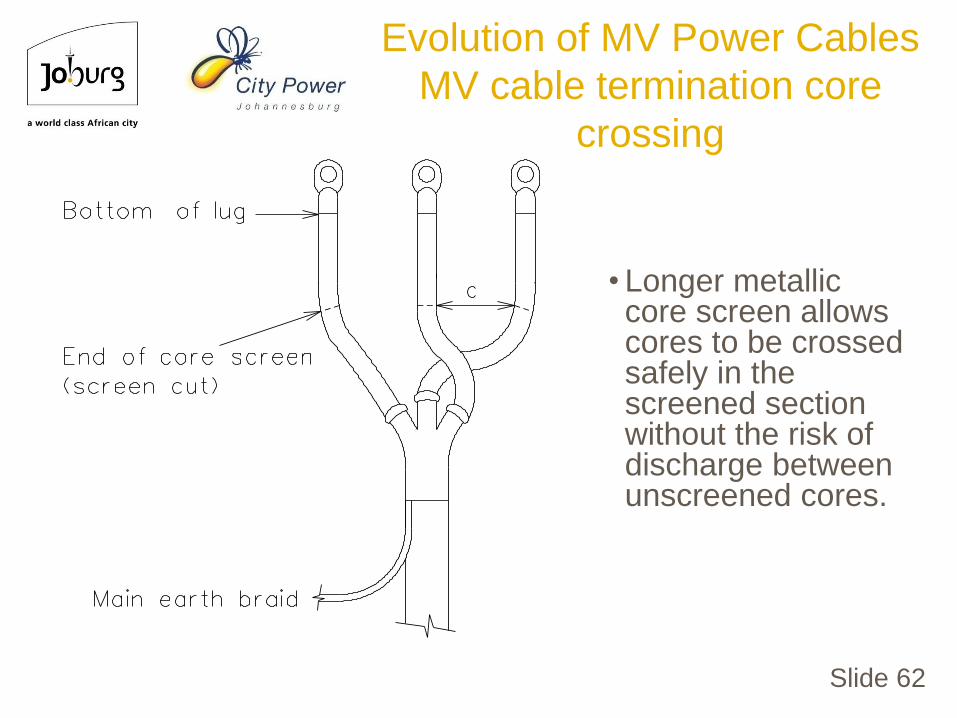
• Longer metallic core screen allows cores to be crossed safely in the screened section without the risk of discharge between unscreened cores.
Evolution of MV Power Cables
MV cable termination core
crossing

Slide 63
Evolution of MV Power Cables
MV cable termination core
crossing (Correctly done)

Slide 64
NRS 012 specifies the following requirements for cable termination and live conductors in air :
– Definitions
– Insulation co-ordination
– Rated insulation levels
– Types of terminations
– Clearances
– Creepage distances
– Cable termination enclosures (boxes)
Evolution of MV Power Cables
MV cable terminations in air-filled
enclosures SANS 876/NRS 012

Slide 66
5 types of terminations:
• Type 1: Bare
• Type 2: Shrouded
• Type 3: Unscreened Separable Connectors (USC)
• Type 4: Screened Separable Connectors – external plugin (SSC)
• Type 5: Screened Separable Connectors - internal plugin (SSC)
Evolution of MV Power Cables
MV cable terminations in air-filled
enclosures SANS 876/NRS 012

Slide 67
• Cable cores terminated with stress
control appropriate to the cable design
and voltage
• Air being the sole insulation medium
for the terminal connections
• The minimum distance from any live
bare metal (e.g. bushing, post
insulator, live conductor, lug, fitting
etc.) to an adjacent phase or to earth
determined by the impulse withstand
voltage requirement
Evolution of MV Power Cables
NRS 012 – Type 1 : Bare (air-
insulated)

Slide 68
Evolution of MV Power Cables
NRS 012 – Type 1 : Bare (air-
insulated)

Slide 71
• Cable cores terminated with stress control
appropriate to the cable design & voltage
• Unscreened local insulation enhancement
at the terminal connections
• The minimum distance from any
unscreened, shrouded, live metal (e.g.
shrouds, cable cores etc.) to an adjacent
phase or to earth determined by power
frequency (e.g. corona inception and
extinction) and impulse withstand voltage
considerations
Evolution of MV Power Cables
NRS 012 – Type 2 : Shrouded

Slide 72
Evolution of MV Power Cables
NRS 012 – Type 2 : Shrouded

Slide 75
Shroud
Unscreened
Stress control
Screened area
Evolution of MV Power Cables
NRS 012 – Type 2 : Shrouded

Slide 76
• Cable cores terminated by stress control
appropriate to the cable design & voltage
• USC at terminal connections
• The minimum distance from any
unscreened, live metal (e.g. USC, cable
cores etc.) to an adjacent phase or to earth
is the same as for a shrouded Type 2
termination.
Evolution of MV Power Cables
NRS 012 – Type 3 : USC

Slide 77
Evolution of MV Power Cables
NRS 012 – Type 3 : USC
Slide 79
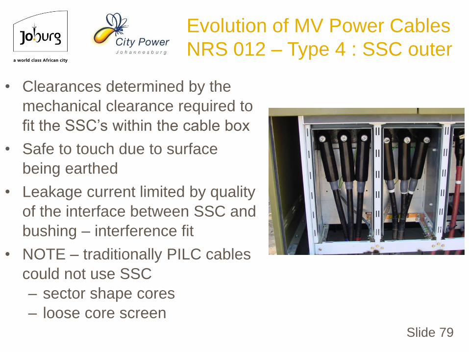
• Clearances determined by the
mechanical clearance required to
fit the SSC’s within the cable box
• Safe to touch due to surface
being earthed
• Leakage current limited by quality
of the interface between SSC and
bushing – interference fit
• NOTE – traditionally PILC cables
could not use SSC
– sector shape cores
– loose core screen
Evolution of MV Power Cables
NRS 012 – Type 4 : SSC outer

Slide 80
Evolution of MV Power Cables
NRS 012 – Type 4 : SSC outer

Slide 81
SSC boots (screened)
Stress cone
Screened (trifurcating kit)
Evolution of MV Power Cables
NRS 012 – Type 4 : SSC outer

Slide 82
Inner cone switchgear
connection system
36 kV up to 1250A
Evolution of MV Power Cables
NRS 012 – Type 5 : SSC Inner
Slide 83
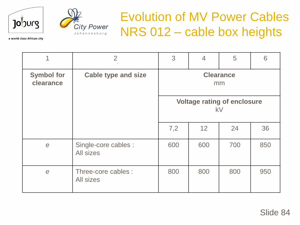
Evolution of MV Power Cables
NRS 012 – cable box heights
Slide 84
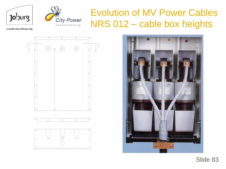
1 2 3 4 5 6
Symbol for
clearance
Cable type and size Clearance
mm
Voltage rating of enclosure
kV
7,2 12 24 36
e Single-core cables :
All sizes
600 600 700 850
e Three-core cables :
All sizes
800 800 800 950
Evolution of MV Power Cables
NRS 012 – cable box heights
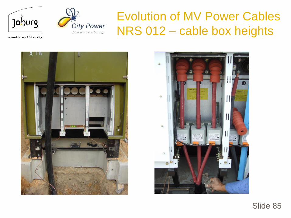
Slide 85
Evolution of MV Power Cables
NRS 012 – cable box heights
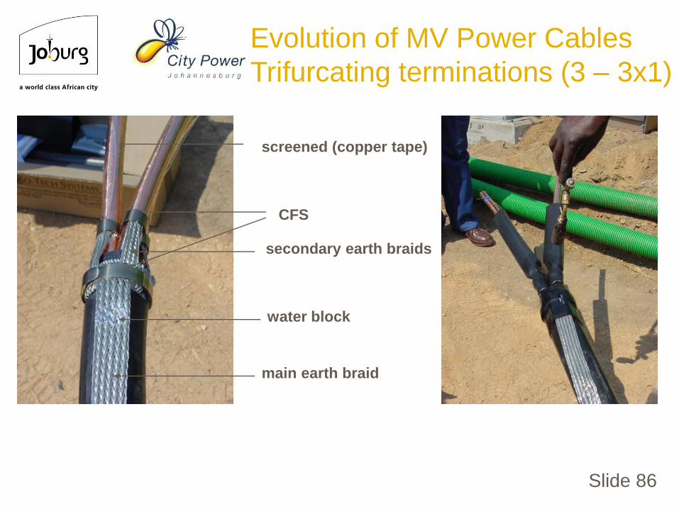
Slide 86
screened (copper tape)
secondary earth braids
main earth braid
water block
CFS
Evolution of MV Power Cables
Trifurcating terminations (3 – 3x1)

Slide 87
Evolution of MV Power Cables
Trifurcating terminations (3 – 3x1)

Slide 88
1 Connector
2 Oil barrier tubing
3 Stress-wedge and oil-blocking void filler
4 Insulation and screen tubes
5 Breakout and trifurcation (1C XLPE–3C PILC)
6 Solderless earth connection
7 Metallic screening
8 Outer sealing and protection
9 Moisture seal
10 Filler
11 Core separator
12 Main earth braid
5 7 1 2 4 3 9 6 8
10 11 12
Evolution of MV Power Cables
Transition joint (3 – 3x1)
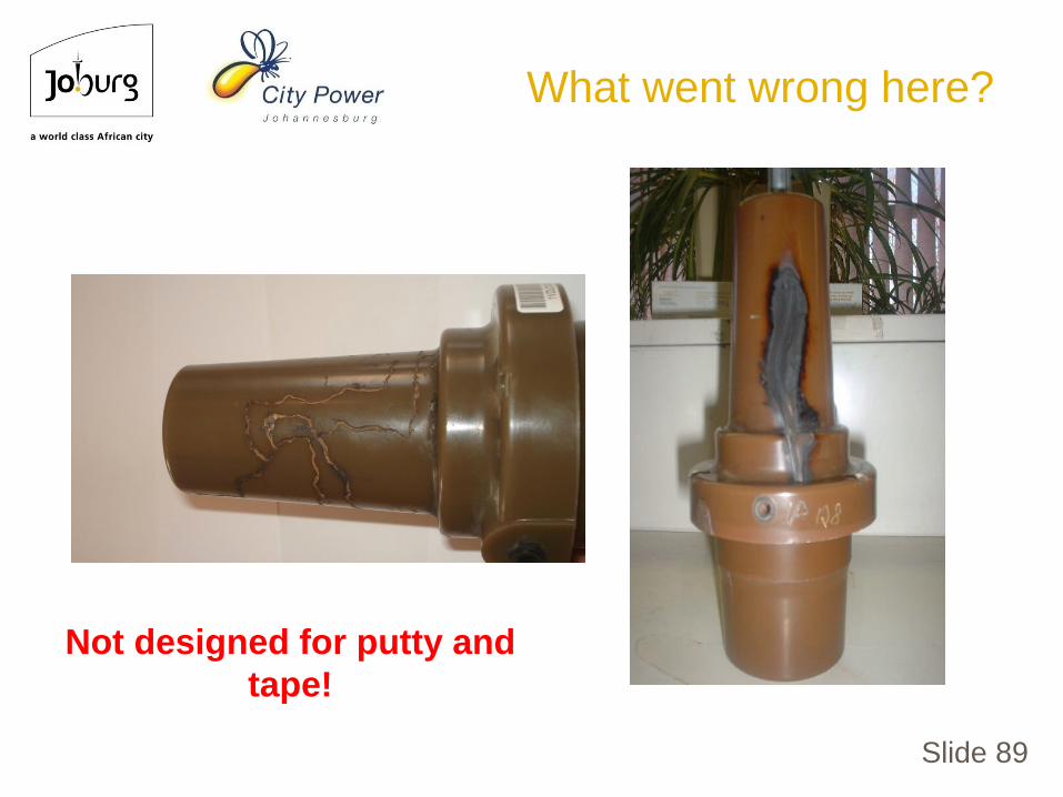
Slide 89
Not designed for putty and
tape!
What went wrong here?

What went wrong here?

What went wrong here?

Slide 92
What went wrong here?

Slide 93
What went wrong here?

Slide 94
What went wrong here?
Slide 95
• Most utilities use d.c. cable pressure test equipment with nodiagnostic results. They have been available for manyyears, portable and cheapest pressure test equipment.
• A high d.c. voltage is applied for a predefined period. Ifnothing trips, the cable is declared healthy to energize.
• This is referred to as “Go or No go” testing.
• Why do failures of the cable, joint or terminations still occurafter energizing?
• d.c. testing only tests the resistivity properties of the cablesystem. However when energized with AC 50Hz the cablesystem the permittivity properties of the components areexperianced.
Evolution of MV Power Cables
MV cable testing

Slide 96
• To ensure future cable system failures are avoided and tomake an informed remaining life decision with regards topossible replacement of the faulted or aged MV power cable.
• With the improved technologies in testing voltage sources,we can test the permittivity properties of the cable systems,and simulate the as in service AC system conditions.
– Very Low Frequency (VLF)
– Damped Oscillating Waveform Test Voltage (DOWTS)
– Alternating Current (AC) @ power frequency
– Resonant Alternating Current (RAC)
Evolution of MV Power Cables
MV cable testing

Slide 97
• A diagnostic test should be conducted before energizing anew cable or after a repair has been made after a failure.
• Off line Tan Delta and PD tests can be performed at thisstage. Results available on site.
• These results provide us with a finger print of the condition.
• So instead of just a “Go or No go” tests, we can now make aninformed decision on the condition of the cable system.
• The revised SANS 10198-13 code of practice for cabletesting, now recommends integrated voltage withstand anddiagnostic test do not take longer to perform as they are nowintegrated in the new available test equipment
Evolution of MV Power Cables
MV cable testing

Slide 98
• The onsite testing of PILC cable systems is complicated dueto the properties of the compound insulation;
• Lots of distributed PD in the cable by design
• Presence of moisture masks PD
• Tan Delta testing is a good indications, but finding theactual problem which a failure could occur from.
• The onsite testing of XLPE cable systems is simplified due tothe properties of the solid insulation;
• No PD in the cable, and
• Jointer mistakes and weak insulation problems can belocated to the approximate distance.
Evolution of MV Power Cables
MV cable testing

99
MV power cable potential
technology changes
• New composite CopperClad Steel (CCS) orCopper Clad Aluminium(CCA) conductors
• Could deter cable theft

Slide 100
• Install screened rather than belted designed PILC cables.
• Select and specify the corrected termination types up front.
• Ensure clearances are kept at all times.
• Ensure jointers are trained to install the MV cable accessories.
• If PILC cable are installed test for moisture always.
• If XLPE cable is installed utilise the right screen removing tool.
• Considered single core cables instead of large 3 core cables.
• Perform combined voltage withstand and diagnostic testing, sothe actual condition of the cable system is now and futurefaults could be avoided.
Evolution of MV Power Cables
Conclusion

101
THE END
(BUT NOT OF EVOLUTION)