Embed Size (px)
Citation preview
hélita® rangeDirect lightning protection
Main catalogue

ABB Hélita® range - Direct lightning protectionn | 1
Hélita® rangeDirect lightning protection
Lightning protection technologies ................................................................................2
Lightning conductor range
ESE typical installation ................................................................................................................6
Early streamer emission lightning rods .....................................................................................8
Simple rods ................................................................................................................................10
Masts .........................................................................................................................................11
Roof fixing accessories .............................................................................................................13
Pylons ........................................................................................................................................14
Lateral fixations .........................................................................................................................15
Conductors and coupling accessories .....................................................................................16
Conductor fasteners .................................................................................................................17
Earth coupling accessories .......................................................................................................18
Earthing system .........................................................................................................................19
Equipotential bonding ...............................................................................................................21
Meshed Cage
Typical installation .....................................................................................................................22
Accessories ...............................................................................................................................23
Index .......................................................................................................................................24
2 | ABB Hélita® range - Direct lightning protection
Lightning protection technologies
Protection against direct lightning strokeTo protect a structure against lightning strokes, a preferred impact point is selected to protect the surrounding struc-ture and conduct the flow of the electric current towards the
ground, with minimal impedance on the path followed by the lightning. Four types of protection systems meet these requirements.
Protection systems Standards
Early streamer emission lightning conductors NF C 17-102 & IEC 62 305-3
Simple rod lightning conductors IEC 62 305-3
Meshed cages IEC 62 305-3
Stretched wires IEC 62 305-3
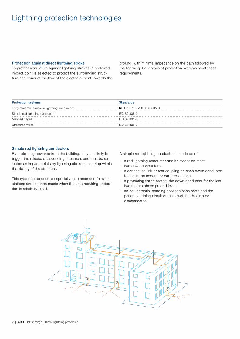
Simple rod lightning conductorsBy protruding upwards from the building, they are likely to trigger the release of ascending streamers and thus be se-lected as impact points by lightning strokes occurring within the vicinity of the structure.
This type of protection is especially recommended for radio stations and antenna masts when the area requiring protec-tion is relatively small.
A simple rod lightning conductor is made up of:
– a rod lightning conductor and its extension mast – two down conductors – a connection link or test coupling on each down conductor
to check the conductor earth resistance – a protecting flat to protect the down conductor for the last
two meters above ground level – an equipotential bonding between each earth and the
general earthing circuit of the structure; this can be disconnected.
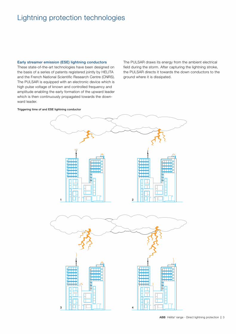
ABB Hélita® range - Direct lightning protection | 3
Early streamer emission (ESE) lightning conductorsThese state-of-the-art technologies have been designed on the basis of a series of patents registered jointly by HELITA and the French National Scientific Research Centre (CNRS). The PULSAR is equipped with an electronic device which is high pulse voltage of known and controlled frequency and amplitude enabling the early formation of the upward leader which is then continuously propagated towards the down-ward leader.
The PULSAR draws its energy from the ambient electrical field during the storm. After capturing the lightning stroke, the PULSAR directs it towards the down conductors to the ground where it is dissipated.
Lightning protection technologies
Triggering time of and ESE lightning conductor
1
3
2
4
4 | ABB Hélita® range - Direct lightning protection
Lightning protection technologies
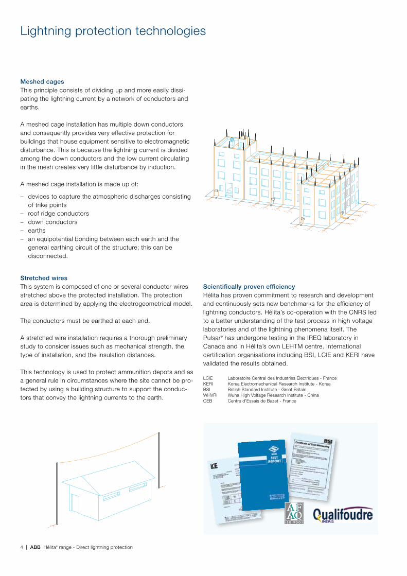
Meshed cagesThis principle consists of dividing up and more easily dissi-pating the lightning current by a network of conductors and earths.
A meshed cage installation has multiple down conductors and consequently provides very effective protection for buildings that house equipment sensitive to electromagnetic disturbance. This is because the lightning current is divided among the down conductors and the low current circulating in the mesh creates very little disturbance by induction.
A meshed cage installation is made up of:
– devices to capture the atmospheric discharges consisting of trike points
– roof ridge conductors – down conductors – earths – an equipotential bonding between each earth and the
general earthing circuit of the structure; this can be disconnected.
Stretched wiresThis system is composed of one or several conductor wires stretched above the protected installation. The protection area is determined by applying the electrogeometrical model.
The conductors must be earthed at each end.
A stretched wire installation requires a thorough preliminary study to consider issues such as mechanical strength, the type of installation, and the insulation distances.
This technology is used to protect ammunition depots and as a general rule in circumstances where the site cannot be pro-tected by using a building structure to support the conduc-tors that convey the lightning currents to the earth.
Scientifically proven efficiencyHélita has proven commitment to research and development and continuously sets new benchmarks for the efficiency of lightning conductors. Hélita’s co-operation with the CNRS led to a better understanding of the test process in high voltage laboratories and of the lightning phenomena itself. The Pulsar® has undergone testing in the IREQ laboratory in Canada and in Hélita’s own LEHTM centre. International certification organisations including BSI, LCIE and KERI have validated the results obtained.
LCIE Laboratoire Central des Industries Électriques - FranceKERI Korea Electromechanical Research Institute - KoreaBSI British Standard Institute - Great BritainWHVRI Wuha High Voltage Research Institute - ChinaCEB Centre d’Essais de Bazet - France
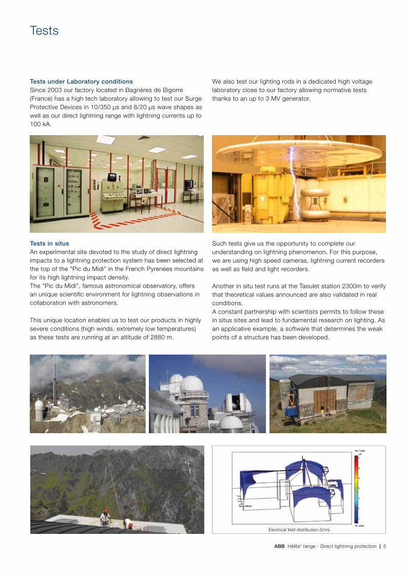
ABB Hélita® range - Direct lightning protection | 5
Tests under Laboratory conditions Since 2003 our factory located in Bagnères de Bigorre (France) has a high tech laboratory allowing to test our Surge Protective Devices in 10/350 µs and 8/20 µs wave shapes as well as our direct lightning range with lightning currents up to 100 kA.
Tests
Tests in situs An experimental site devoted to the study of direct lightning impacts to a lightning protection system has been selected at the top of the "Pic du Midi" in the French Pyrenées mountains for its high lightning impact density. The "Pic du Midi", famous astronomical observatory, offers an unique scientific environment for lightning observations in collaboration with astronomers.
This unique location enables us to test our products in highly severe conditions (high winds, extremely low temperatures) as these tests are running at an altitude of 2880 m.
Such tests give us the opportunity to complete our understanding on lightning phenomenon. For this purpose, we are using high speed cameras, lightning current recorders as well as field and light recorders.
Another in situ test runs at the Taoulet station 2300m to verify that theoretical values announced are also validated in real conditions.A constant partnership with scientists permits to follow these in situs sites and lead to fundamental research on lighting. As an applicative example, a software that determines the weak points of a structure has been developed.
Electrical field distribution (V/m)
We also test our lighting rods in a dedicated high voltage laboratory close to our factory allowing normative tests thanks to an up to 3 MV generator.
6 | ABB Hélita® range - Direct lightning protection
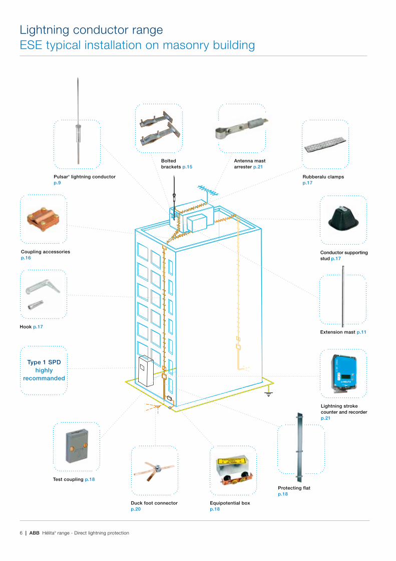
Lightning conductor rangeESE typical installation on masonry building
Pulsar® lightning conductorp.9
Coupling accessoriesp.16
Hook p.17
Type 1 SPD highly
recommanded
Test coupling p.18
Duck foot connectorp.20
Lightning stroke counter and recorderp.21
Extension mast p.11
Conductor supportingstud p.17
Rubberalu clampsp.17
Antenna mast arrester p.21
Boltedbrackets p.15
Protecting flatp.18
Equipotential box p.18
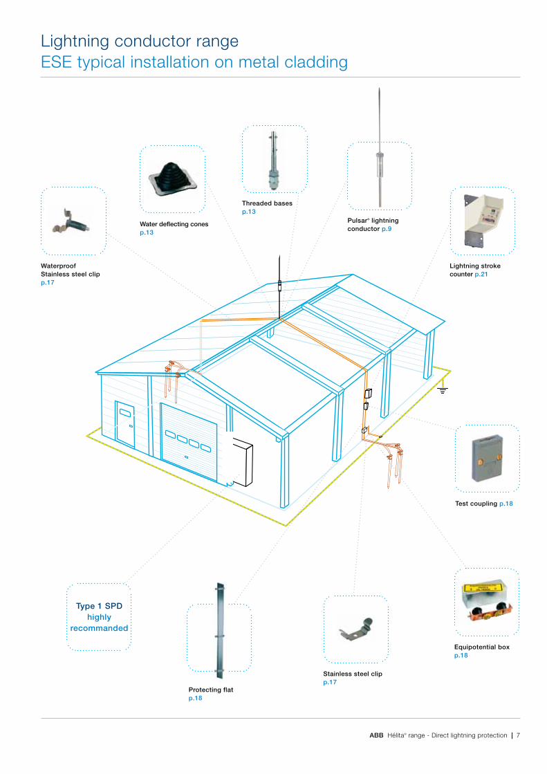
ABB Hélita® range - Direct lightning protection | 7
Lightning conductor rangeESE typical installation on metal cladding
Pulsar® lightning conductor p.9
Threaded bases p.13
Test coupling p.18
Equipotential boxp.18
Lightning stroke counter p.21
Stainless steel clipp.17
Protecting flatp.18
Water deflecting conesp.13
WaterproofStainless steel clipp.17
Type 1 SPD highly
recommanded

8 | ABB Hélita® range - Direct lightning protection
Lightning conductor range Early streamer emissionPulsar®, the high pulse voltage, initiation advance lightning conductor
In ongoing collaboration with the CNRS (French National Research Organisation), Hélita continues to innovate, and has developed a new generation of lightning devices. The new Pulsar® range with increased initiation advance performances, represents further progress in terms of protection, operating autonomy and ease of maintenance. These advancements reinforce Hélita‘s position as International leader in direct lightning protection with over 200 000 installations through-out the world.
Hélita manufacturing qualityThe enviable reputation of the Pulsar® has been earned through maintaining a consistently high quality in manufac-ture. Before leaving the factory, each Pulsar® has been tested for installation breakdown at high voltage, and subjected to a current test that ensures its performance when conduct-ing lightning discharges. The high voltage output pulses at the Pulsar® are also examined to verify correct amplitude and frequency. The Pulsar® is built to withstand the arduous conditions encountered in service, and its ongoing perform-ance can be monitored simply and quickly using the Pulsar® test set.
The advantage of initiation advanceThe unique efficiency of the Pulsar® lightning conductor is based on a specific initiation advance, well before the natural formation of an upward leader, the Pulsar® generates a leader that rapidly propagates to capture the lightning and direct it to earth. Validated in the laboratory, this gain in time relative to the simple rod provides additional essential protection.
Complete autonomyDuring a storm the ambient electric field may rise to between 10 to 20 kV/m. As soon as the field exceeds a threshold rep-resenting the minimum risk of a lightning strike, the Pulsar® lightning terminal is activated. It draws its energy from the ambient electric field the energy required to generate high voltage pulses, creating and propagating an upward leader. No other power sources are required, and no radioactive components are used.
Upward leaders Meeting pointReturn arc
A B C D
Pulsar® Upward leaders Meeting point
A B C D
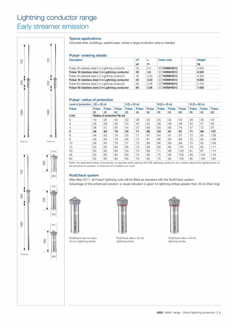
ABB Hélita® range - Direct lightning protection | 9
230
ø74
ø60
200
ø74
ø60
260
ø74
ø60
1080
200
725
1080
230
725
Pulsar 30
1080
260
725
Pulsar 60
Pulsar 45
RodCheck has not been hit by a lightning stroke
RodCheck after a 50 kA lightning stroke
RodCheck after a 25 kA lightning stroke
Lightning conductor rangeEarly streamer emission
Typical applicationsIndustrial sites, buildings, warehouses, where a large protection area is needed.
Pulsar® ordering detailsDescription ∆T L Order code Weight
µs m kg
Pulsar 30 stainless steel 2 m Lightning conductor 30 2.0 2CTH0IMH3012 5.000Pulsar 30 stainless steel 3 m Lightning conductor 30 3.0 2CTH0IMH3013 6.500Pulsar 45 stainless steel 2 m Lightning conductor 45 2.03 2CTH0IMH4512 5.300Pulsar 45 stainless steel 3 m Lightning conductor 45 3.03 2CTH0IMH4513 6.800Pulsar 60 stainless steel 2 m Lightning conductor 60 2.06 2CTH0IMH6012 5.700Pulsar 60 stainless steel 3 m Lightning conductor 60 3.06 2CTH0IMH6013 7.000
Pulsar® radius of protectionLevel of protection I (D = 20 m) II (D = 30 m) III (D = 45 m) IV (D = 60 m)
Pulsar Pulsar 30
Pulsar 45
Pulsar 60
Pulsar 30
Pulsar 45
Pulsar 60
Pulsar 30
Pulsar 45
Pulsar 60
Pulsar 30
Pulsar 45
Pulsar 60
h (m) Radius of protection Rp (m)2 19 25 32 22 28 35 25 32 40 28 36 443 28 38 48 33 42 52 38 48 59 42 57 654 38 51 64 44 57 69 50 65 78 57 72 875 48 63 79 55 71 86 63 81 97 71 89 1076 48 63 79 55 71 87 64 81 97 72 90 1088 49 64 79 56 72 87 66 83 99 75 92 10910 49 64 79 57 72 88 66 83 99 75 92 10915 50 65 80 58 73 89 69 85 101 78 95 11120 50 65 80 59 74 89 71 86 102 81 97 11345 50 65 80 60 75 90 75 90 105 89 104 11960 50 65 80 60 75 90 75 90 105 90 105 120Note: the optimized radius of protection is reached when placing the ESE lightning conductor at 5 meters above the highest point of the structure to protect. A minimum of 2 meters is a must.
RodCheck systemAfter May 2011, all Pulsar® lightning rods will be fitted as standard with the RodCheck system. Advantage of this enhanced solution: a visual indication is given for lightning strikes greater than 25 kA (Red ring)
10 | ABB Hélita® range - Direct lightning protection
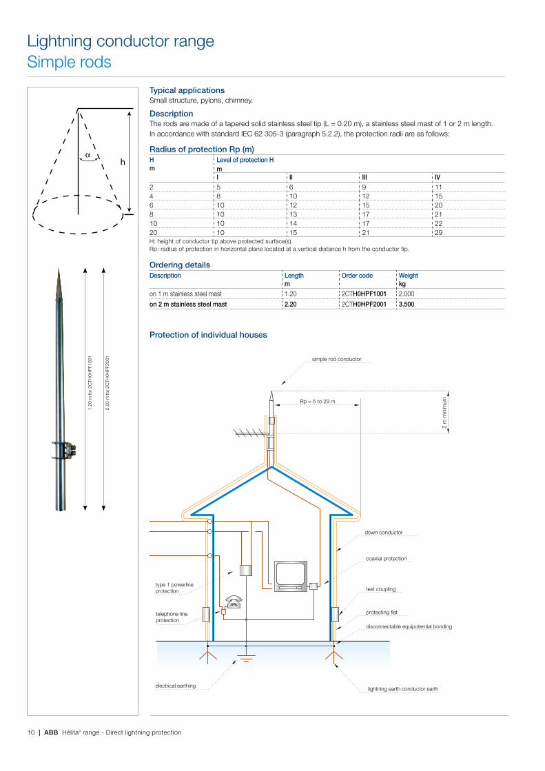
Typical applicationsSmall structure, pylons, chimney.
DescriptionThe rods are made of a tapered solid stainless steel tip (L = 0.20 m), a stainless steel mast of 1 or 2 m length.In accordance with standard IEC 62 305-3 (paragraph 5.2.2), the protection radii are as follows:
Radius of protection Rp (m)Hm
Level of protection HmI II III IV
2 5 6 9 114 8 10 12 156 10 12 15 208 10 13 17 2110 10 14 17 2220 10 15 21 29H: height of conductor tip above protected surface(s).Rp: radius of protection in horizontal plane located at a vertical distance h from the conductor tip.
Ordering detailsDescription Length Order code Weight
m kgon 1 m stainless steel mast 1.20 2CTH0HPF1001 2.000
on 2 m stainless steel mast 2.20 2CTH0HPF2001 3.500
Protection of individual houses
αh
1.20
m fo
r 2C
TH0H
PF1
001
2.20
m fo
r 2C
TH0H
PF2
001
PROTECTION OF INDIVIDUAL HOUSES
2 m
min
imum
protecting flat
disconnectable equipotential bonding
type 1 powerlineprotection
telephone lineprotection
coaxial protection
lightning earth conductor earth
test coupling
down conductor
simple rod conductor
Rp = 5 to 29 m
electrical earthing
Lightning conductor rangeSimple rods
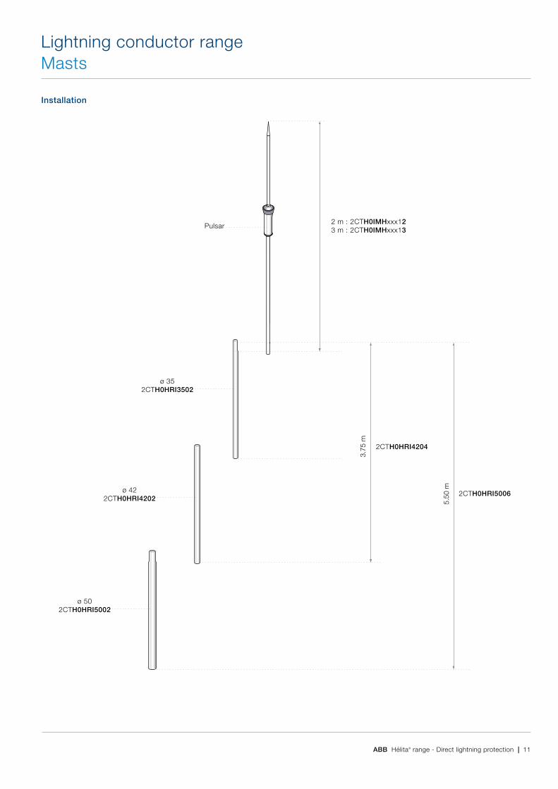
ABB Hélita® range - Direct lightning protection | 11
Installation
Lightning conductor rangeMasts
ø 352CTH0HRI3502
ø 422CTH0HRI4202
ø 502CTH0HRI5002
2 m : 2CTH0IMHxxx123 m : 2CTH0IMHxxx13
3.75
m
5.50
m2CTH0HRI4204
2CTH0HRI5006
Pulsar

12 | ABB Hélita® range - Direct lightning protection
DescriptionThe interlocking extension masts reach a maximum height of 5.75 m, i.e. 7.60 m when equipped with a 2 m lightning conductor.Material: stainless steel.
Ordering detailsDescription Length Order code Weight
m kgStainless steel mast ø 35 / int. 31 2 2CTH0HRI3502 3.400Stainless steel mast Ø 35 / int. 31 3 2CTH0HRI3503 5.200Stainless steel mast ø 42 / int. 36 2 2CTH0HRI4202 6.400Stainless steel mast ø 42 / int. 36 3 2CTH0HRI4203 9.600Stainless steel mast ø 50 / int. 44 2 2CTH0HRI5002 7.500Set of 2 stainless steel masts / int. 44 3.75 2CTH0HRI4204 9.800Set of 2 stainless steel masts / int. 44 5.75 2CTH0HRI4206 14.800Set of 3 stainless steel masts / int. 44 5.50 2CTH0HRI5006 17.300Stainless steel extension mast ø 50 / int. 44 3 2CTH0HRI5003 11.000
DescriptionMast configuration without guying kit for a wind below 140 km/h and more than 6 km away from the sea.
Nominal height Conductor type Mast typem4 2CTH0IMHxx12 2CTH0HRI35025 2CTH0IMHxx13 2CTH0HRI35026 2CTH0IMHxx13 2CTH0HRI35037 2CTH0IMHxx13 2CTH0HRI3502 + 2CTH0HRI4202 = 2CTH0HRI42048 2CTH0IMHxx12 2CTH0HRI3503 + 2CTH0HRI4203 = 2CTH0HRI4206
DescriptionMast configuration without guying kit for a wind below 170 km/h.
Nominal height Conductor type Mast typem4 2CTH0IMHxx12 2CTH0HRI35025 2CTH0IMHxx13 2CTH0HRI35026 2CTH0IMHxx12 2CTH0HRI3502 + 2CTH0HRI4202 = 2CTH0HRI42047 2CTH0IMHxx13 2CTH0HRI3502 + 2CTH0HRI4202 = 2CTH0HRI42048 2CTH0IMHxx12 2CTH0HRI3502 + 2CTH0HRI4202 + 2CTH0HRI5002 = 2CTH0HRI5006For wind speed above 170 km/h a guying must be used.
Lightning conductor rangeMasts
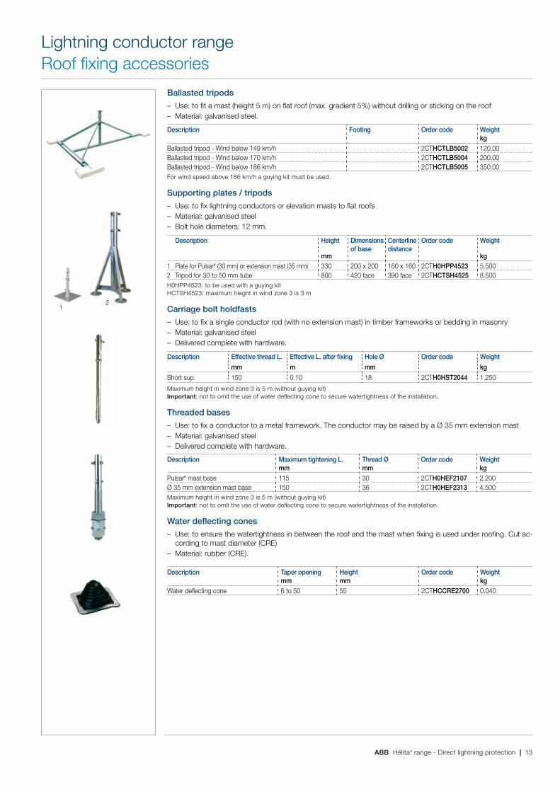
ABB Hélita® range - Direct lightning protection | 13
Ballasted tripods
– Use: to fit a mast (height 5 m) on flat roof (max. gradient 5%) without drilling or sticking on the roof – Material: galvanised steel.
Description Footing Order code Weightkg
Ballasted tripod - Wind below 149 km/h 2CTHCTLB5002 120.00Ballasted tripod - Wind below 170 km/h 2CTHCTLB5004 200.00Ballasted tripod - Wind below 186 km/h 2CTHCTLB5005 350.00For wind speed above 186 km/h a guying kit must be used.
Supporting plates / tripods
– Use: to fix lightning conductors or elevation masts to flat roofs – Material: galvanised steel – Bolt hole diameters: 12 mm.
Description Height Dimensions of base
Centerline distance
Order code Weight
mm kg1 Plate for Pulsar® (30 mm) or extension mast (35 mm) 330 200 x 200 160 x 160 2CTH0HPP4523 5.5002 Tripod for 30 to 50 mm tube 800 420 face 390 face 2CTHCTSH4525 8.500H0HPP4523: to be used with a guying kit HCTSH4523: maximum height in wind zone 3 is 3 m
Carriage bolt holdfasts
– Use: to fix a single conductor rod (with no extension mast) in timber frameworks or bedding in masonry – Material: galvanised steel – Delivered complete with hardware.
Description Effective thread L. Effective L. after fixing Hole Ø Order code Weight
mm m mm kg
Short sup. 150 0.10 18 2CTH0HST2044 1.250
Maximum height in wind zone 3 is 5 m (without guying kit) Important: not to omit the use of water deflecting cone to secure watertightness of the installation.
Threaded bases
– Use: to fix a conductor to a metal framework. The conductor may be raised by a ø 35 mm extension mast – Material: galvanised steel – Delivered complete with hardware.
Description Maximum tightening L. Thread Ø Order code Weightmm mm kg
Pulsar® mast base 115 30 2CTH0HEF2107 2.200ø 35 mm extension mast base 150 36 2CTH0HEF2313 4.500Maximum height in wind zone 3 is 5 m (without guying kit) Important: not to omit the use of water deflecting cone to secure watertightness of the installation.
Water deflecting cones
– Use: to ensure the watertightness in between the roof and the mast when fixing is used under roofing. Cut ac-cording to mast diameter (CRE)
– Material: rubber (CRE).
Description Taper opening Height Order code Weightmm mm kg
Water deflecting cone 6 to 50 55 2CTHCCRE2700 0.040
Lightning conductor rangeRoof fixing accessories
12

14 | ABB Hélita® range - Direct lightning protection
Self carrying pylons
– Material: hot galvanised steel – These pylons are made of a welded steel lattice with a triangular cross-section. Each element is 3 m in length,
except the ground anchoring section (about 1 m). – Delivered complete with stainless steel hardware and Hélita ø 35 mm mast head (to receive Pulsar® mast) – The concrete anchorage blocks should be made with concrete in a proportion of 350 kg/m3 and calculated for
a good ground.
Height * Self-supporting m
Zone I136 km/h
Zone II149 km/h
Zone III167 km/h
Zone IV183 km/h
9 2CTHCHPA0109 2CTHCHPA0209 2CTHCHPA0309 2CTHCHPA040912 2CTHCHPA0112 2CTHCHPA0212 2CTHCHPA0312 2CTHCHPA041215 2CTHCHPA0115 2CTHCHPA0215 2CTHCHPA0315 2CTHCHPA041518 2CTHCHPA0118 2CTHCHPA0218 2CTHCHPA0318 2CTHCHPA0418* Other sizes on request - Technical specifications available - For wind zone V (210 km/h) please consult us.
Guyed pylons
– Material: hot galvanised steel – These pylons are made of a welded steel lattice with a triangular cross-section (centerline distance 175 mm)
supplied in lengths of 3 or 6 m – Use: lightning conductor supports for flat roofs – Fibre glass guying (1 set per section) – Delivered complete with base and neoprene tile, Hélita ø 35 mm mast head, fibre glass and accessories (an-
choring clips and stay tighteners) for guying, with bolted anchoring.
Height * Guyedm Zones I and II9 2CTHCHPH090012 2CTHCHPH120015 2CTHCHPH150018 2CTHCHPH1800* Other sizes on request - Technical specifications available - For wind zone V (210 km/h) please consult us.
Guying kit for lightning rod with mast
Complete kit with: – 25 m of fibre glass cable – 6 anchoring clips – 3 stay tighteners – 3 ring fasteners – 1 3-directional clamp – 1 base (2CTHCHPP4523).
Description Order code Weightkg
Guying kit 2CTH0HKH0025 12.000
OBSTA obstruction lights
The OBSTA HISTI is an obstruction light for hazard to low-flying aircraft for airport, building, broadcast transmit-ting towers, chimneys, bridges and transmission lines. This lamp based on cold neon discharge principle offers high reliability, robustness in hostile environments (EMC, climatic...), proven long life (more than 25 000 hours) on all kinds of obstacle like transmission lines, TV towers and exposure in electromagnetic fields and high tempera-ture. One unique model will adjust itself to the main supply voltages, continuously from 100 V to 240 Vrms 50/60 Hz.
Description Order code Weightkg
OBSTA HISTI 110 to 240 V 2CTHCHCO0071 5.000OBSTA photoelectric cell 230 V 2CTHCHCO0752 0.400
Incendescent obstruction lights
Simple obstruction light of very simple conception with special lamp 55 W - 230 V (2CTHCFOH2101) having an average life time of 8 000 hours.
Description Order code Weightkg
1 Single obstruction light - H 190 mm - ø 110 mm 2CTHCFOH2100 1.4002 Support plate with studs for obstruction light - H 145 mm 2CTHCFOH2101 0.600
55 W lamp - 230 V - 8 000 hours 2CTHCFOH2201
Lightning conductor rangePylons
Pulsar
guying ring
base
�ber glass guy
stay tightener
anchor
masts
1
2
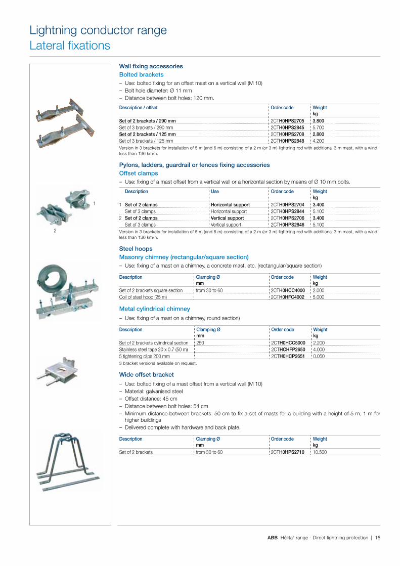
ABB Hélita® range - Direct lightning protection | 15
Wall fixing accessoriesBolted brackets – Use: bolted fixing for an offset mast on a vertical wall (M 10) – Bolt hole diameter: ø 11 mm – Distance between bolt holes: 120 mm.
Description / offset Order code Weightkg
Set of 2 brackets / 290 mm 2CTH0HPS2705 3.800Set of 3 brackets / 290 mm 2CTH0HPS2845 5.700Set of 2 brackets / 125 mm 2CTH0HPS2708 2.800Set of 3 brackets / 125 mm 2CTH0HPS2848 4.200Version in 3 brackets for installation of 5 m (and 6 m) consisting of a 2 m (or 3 m) lightning rod with additional 3 m mast, with a wind less than 136 km/h.
Pylons, ladders, guardrail or fences fixing accessoriesOffset clamps – Use: fixing of a mast offset from a vertical wall or a horizontal section by means of ø 10 mm bolts.
Description Use Order code Weightkg
1 Set of 2 clamps Horizontal support 2CTH0HPS2704 3.400Set of 3 clamps Horizontal support 2CTH0HPS2844 5.100
2 Set of 2 clamps Vertical support 2CTH0HPS2706 3.400Set of 3 clamps Vertical support 2CTH0HPS2846 5.100
Version in 3 brackets for installation of 5 m (and 6 m) consisting of a 2 m (or 3 m) lightning rod with additional 3 m mast, with a wind less than 136 km/h.
Steel hoopsMasonry chimney (rectangular/square section) – Use: fixing of a mast on a chimney, a concrete mast, etc. (rectangular/square section)
Description Clamping Ø Order code Weightmm kg
Set of 2 brackets square section from 30 to 60 2CTH0HCC4000 2.000Coil of steel hoop (25 m) 2CTH0HFC4002 5.000
Metal cylindrical chimney
– Use: fixing of a mast on a chimney, round section)
Description Clamping Ø Order code Weightmm kg
Set of 2 brackets cylindrical section 250 2CTH0HCC5000 2.200Stainless steel tape 20 x 0.7 (50 m) 2CTHCHFP2650 4.0005 tightening clips 200 mm 2CTH0HCP2651 0.0503 bracket versions available on request.
Wide offset bracket
– Use: bolted fixing of a mast offset from a vertical wall (M 10) – Material: galvanised steel – Offset distance: 45 cm – Distance between bolt holes: 54 cm – Minimum distance between brackets: 50 cm to fix a set of masts for a building with a height of 5 m; 1 m for
higher buildings – Delivered complete with hardware and back plate.
Description Clamping Ø Order code Weightmm kg
Set of 2 brackets from 30 to 60 2CTH0HPS2710 10.500
Lightning conductor rangeLateral fixations
1
2
16 | ABB Hélita® range - Direct lightning protection
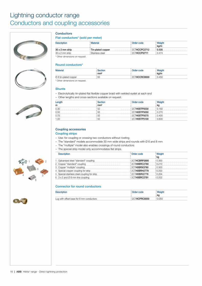
ConductorsFlat conductors* (sold per meter)
Description Material Order code Weightkg/m
30 x 2 mm strip Tin-plated copper 2CTHCCPC2712 0.53530 x 2 mm strip Stainless steel 2CTHCCPI2711 0.474* Other dimensions on request.
Round conductors*
Material Section Order code Weightmm² kg/m
ø 8 tin-plated copper 50 2CTHCCRC8000 0.450* Other dimensions on request.
Shunts
– Electrolytically tin-plated flat flexible copper braid with welded eyelet at each end – Other lengths and cross-sections available on request.
Length Section Order code Weightm mm² kg0.30 50 2CTH0STP5030 0.1600.50 50 2CTH0STP5050 0.2700.75 50 2CTH0STP5075 0.4001.00 50 2CTH0STP5100 0.600
Coupling accessoriesCoupling strips – Use: for coupling or crossing two conductors without riveting – The "standard" models accommodate 30 mm wide strips and rounds with ø 6 and 8 mm – The "multiple" model also enables crossings of round conductors – The special strip model only accommodates flat strips.
Description Order code Weightkg
1 Galvanised steel "standard" coupling 2CTHCBRP2680 0.3002 Copper "standard" coupling 2CTH0BRC2780 0.2103 Copper "multiple" coupling 2CTH0BRX3780 0.3004 Special copper coupling for strip 2CTH0BRH2779 0.2005 Special stainless steel coupling for strip 2CTH0BRI2779 0.2046 3 x 2 and ø 8 mm line coupling 2CTH0BRC2781 0.202
Connector for round conductors
Description Order code Weightkg
Lug with offset base for 8 mm conductors 2CTHCPRC8000 0.050
Lightning conductor rangeConductors and coupling accessories
1 2
4 3
5
6

ABB Hélita® range - Direct lightning protection | 17
Roof fixing accessoriesConductor supporting studs – Material: black synthetic exterior filled with cement (except 2CTHCHPV2771 to be filled up by your means) – Eliminates the need to drill through waterproofing to attach the conductor – Can be glued with neoprene glue – Height: 8 cm.
Description Use Order code Weightkg
1 Hollow stud ø 8 mm conductor 30 x 2 mm conductor Cable raceway
2CTHCHPV2771 0.160
2 Solid stud (clip) Ø 8 mm conductor 30 x 2 mm conductor
2CTHCHPB2772 1.290
Ruberalu brackets for flat roof with waterproofing
– Material: bituminised aluminium – These brackets are attached by hot-melt gluing.
Dimensions Order code Weightmm kg150 x 40 2CTH0HBR2717 0.020Rolls also available
Wall fixing accessories for flat conductorsHook for masonry walls – Fixing: on masonry by driving into lead dowels – For flat strip.
Description Material Order code Weightkg
Hook 30 mm Galvanised steel 2CTH0HCM2704 0.014Dowel Lead 2CTH0HCC2696 0.003
Stainless steel clips
– Material: stainless steel – For fixing a flat strip conductor – Fixed with pop rivets or screws (ø 4 mm) not supplied.
Description Order code Weightkg
1 Stainless steel clips for 30 x 2 2CTH0HBI2703 0.0022 50 aluminium waterproof pop rivets ø 4 2CTH0HRP2705 0.1003 Stainless steel clip for waterproof cladding for 30 x 2 2CTH0HCB4240 0.005
Wall fixing accessories for round conductors
Description Order code Weightkg
4 Grey PVC fixture 2CTH0HAR2445 0.0075 Grey clipped tile fastener 2CTH0HAR2745 0.045
Pylon or ladder fixing accessories for round or flat conductorStainless steel collars – Use: to clamp conductors on tube supports – Material: stainless steel.
Tightening Ø Order code Weightmm kg30 to 50 2CTHCHCI2419 0.01540 to 70 2CTHCHCI2420 0.02060 to 100 2CTHCHCI2421 0.025
Lightning conductor rangeConductor fasteners
1
2
1
2
3
4
5
18 | ABB Hélita® range - Direct lightning protection
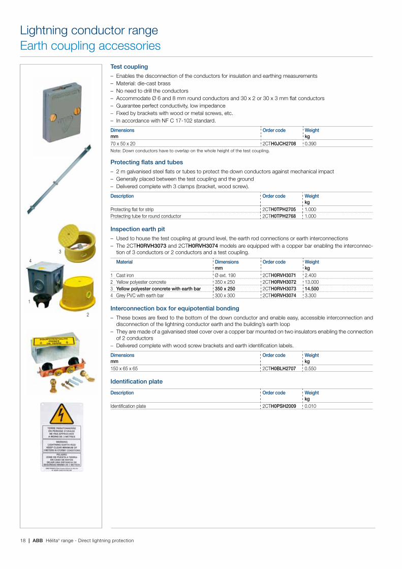
Test coupling
– Enables the disconnection of the conductors for insulation and earthing measurements – Material: die-cast brass – No need to drill the conductors – Accommodate ø 6 and 8 mm round conductors and 30 x 2 or 30 x 3 mm flat conductors – Guarantee perfect conductivity, low impedance – Fixed by brackets with wood or metal screws, etc. – In accordance with NF C 17-102 standard.
Dimensions Order code Weightmm kg70 x 50 x 20 2CTH0JCH2708 0.390Note: Down conductors have to overlap on the whole height of the test coupling.
Protecting flats and tubes
– 2 m galvanised steel flats or tubes to protect the down conductors against mechanical impact – Generally placed between the test coupling and the ground – Delivered complete with 3 clamps (bracket, wood screw).
Description Order code Weightkg
Protecting flat for strip 2CTH0TPH2705 1.000Protecting tube for round conductor 2CTH0TPH2768 1.000
Inspection earth pit
– Used to house the test coupling at ground level, the earth rod connections or earth interconnections – The 2CTH0RVH3073 and 2CTH0RVH3074 models are equipped with a copper bar enabling the interconnec-
tion of 3 conductors or 2 conductors and a test coupling.
Material Dimensions Order code Weightmm kg
1 Cast iron ø ext. 190 2CTH0RVH3071 2.4002 Yellow polyester concrete 350 x 250 2CTH0RVH3072 13.0003 Yellow polyester concrete with earth bar 350 x 250 2CTH0RVH3073 14.5004 Grey PVC with earth bar 300 x 300 2CTH0RVH3074 3.300
Interconnection box for equipotential bonding
– These boxes are fixed to the bottom of the down conductor and enable easy, accessible interconnection and disconnection of the lightning conductor earth and the building’s earth loop
– They are made of a galvanised steel cover over a copper bar mounted on two insulators enabling the connection of 2 conductors
– Delivered complete with wood screw brackets and earth identification labels.
Dimensions Order code Weightmm kg150 x 65 x 65 2CTH0BLH2707 0.550
Identification plate
Description Order code Weightkg
Identification plate 2CTH0PSH2009 0.010
Lightning conductor rangeEarth coupling accessories
1
2
4
3

ABB Hélita® range - Direct lightning protection | 19
OverviewEach down conductor in a lightning protection system must be connected to an earth termination system designed to carry away the lightning current. The earth termination system must fulfil three indispensable conditions:
– The earth termination resistance value French and other international standards, as well as the technical requirements of a number of authorities stipulate an earth termination resistance value of less than 10 ohms. This value should be measured on the earth connection isolated from any other conductive component. If the resistance value of 10 ohms cannot be achieved, the
General earth systemDuck's foot earth termination systemThe minimum earth termination system is made up of 25 meters of 30 x 2 mm tin-plated copper strip, split into 3 strands buried in 3 trenches at a depth of 60 to 80 cm dug in a fan shape like a duck’s foot: one end of the longest strand is connected to the test coupling, the two other strands being linked to a special connection known as a duck’s foot connector.
Lightning conductor rangeEarthing system
protection �at
30 x 2 strip
3 m1 m from walldepth
60 to 80 cm
4 m
stainless steel clamp
NB: the earth termination is covered by a red or orange warning grid
DUCK'S FOOT SYSTEM FOR A MESHED CAGE
duck's foot connector
protection �at
30 x 2 strip
2 m
1 m from walldepth 60 to 80 cm
stainless steel clamp
NB: the earth termination is covered by a red or orange warning grid 2 m rod
eart
h ro
d
clam
p
ROD TRIANGLE EARTH TERMINATION SYSTEM
DUCK'S FOOT EARTH TERMINATION SYSTEM WITH EARTH RODS
protection �at
30 x 2 strip
8 to 12 m
6 to 9 mdepth 60 to 80 cm
duck's foot connector
stainless steel clamp
NB: the earth termination is covered by a red or orange warning grid
rod
eart
h ro
d
clam
p
1 m from wall
Standard list of material
Rod systemDescription Order code Nb of pcs or mDuck's foot connector 2CTH0RPO2840 1 pcFlat conductor 2CTHCCPC2712 10 mSelf-extensible earth rod 2CTHCPVB2010 6 pcsManual snap tool ø 19 2CTHCBMA0019 1 pcEarth rod clamp 2CTH0CRH4020 3 pcsNote: The earth termination is covered by a red or orange warning grid.
Rod triangle earth termination systemWhen the site topography does not lend itself to the installa-tion of a duck’s foot as described above, an earth termination system can be developed using at least 3 copper earth rods each with a minimum length of 2 m, buried vertically in the ground: the rods should be spaced at intervals of about 2 m and at a mandatory distance of 1 m to 1.5 m from the foundations.
Duck's foot earth termination system with earth rodsIf the soil type is not altogether suitable for a duck’s foot con-nector, a combination of duck’s foot and earth rods will significantly enhance protection. In this case, the end of each duck’s foot connector strand is connected to an earth rod.
Standard list of material
Description Order code Nb of pcs or mDuck's foot connector 2CTH0RPO2840 1 pcFlat conductor 2CTHCCPC2712 25 mNote: The earth termination is covered by a red or orange warning grid.
earth termination is nonetheless considered compliant if it is made up of at least 100 m of conductors or electrodes, each section measuring no more than 20 m (for level of protection 2, 3 and 4) and 160 m (8 x 20 m) for level 1.
– Equipotential bonding Standards require the equipotential bonding of lightning conductor earth termination systems with the existing earthing systems.
– Inspection earth pit The connection parts between lightning earth system and electrical system test coupling can be accessed by an inspection pit.
Standard list of material
Rod systemDescription Order code Nb of pcs or mDuck's foot connector 2CTH0RPO2840 1 pcFlat conductor 2CTHCCPC2712 25 mStandard copperbond rod, 2 m 2CTH0PCS1920 3 pcsManual snap tool ø 19 2CTHCBMA0019 1 pcEarth rod clamp 2CTH0CRH4020 3 pcsNote: The earth termination is covered by a red or orange warning grid.

20 | ABB Hélita® range - Direct lightning protection
Earth rods
– The use of a reusable treated steel snap tool is compulsory to protect the rod head when driving in
Description Order code Weightkg
1 Galvanised steel rod ø 20 - L. 1 m 2CTHCPVB2010 2.4002 Standard copperbond earth rod ø 19 - L. 210 m 2CTHCPCS19203 Manual snap tool ø 19* 2CTHCBMA0019 0.3004 Earth rod clamp for 30 x 2 strip 2CTH0CRH4020 0.150(1) 2CTHCPVB2010: high resistance steel tube hot galvanised (2) 2CTHCPCS1920: high corrosion resistance due to a 250 µ thickness of electrolytically plated copper (3) 2CTHCBMA0019: manual snap tool - one for 3 rods to be hammered in
Duck foot connectors
– Zinc-plated, die-cast brass parts enabling the connection of three of four strands of tin-plated copper 30 x 2 mm conductor strip
– Variable strand angles – Perfect electrical conductivity and strong tightening.
Description Order code Weightkg
Duck foot connector ø 85 - thickness 30 mm 2CTH0RPO2840 0.800
Earth grids
– Earth grids are made of solid red copper with a mesh size of 115 x 40 mm.
Description Thickness Order code Weightmm kg
Earth grid 0.66 x 0.92 m * 3 2CTHCGMD6692 3.800Earth grid 1.00 x 2.00 m ** 3 2CTHCGMD1020 8.400* Equivalent to 18 m of ø 8 mm round conductor ** Equivalent to 54 m of ø 8 mm round conductor
Digital earth test set
– Battery-powered and watertight the 2CTHCACA6460 is a device that is easy to use and has been designed for operation in the field
– On all installations requiring the qualification of electrical or lightning conductor earths, using traditional earth rod methods, the 2CTHCACA6460 measures the earth resistance and resistivity of the soil.
Description Order code Weightkg
1 Digital earth and resistivity test set 2CTHCACA6460 1.300Housing for test set with accessories (4 leads + 4 rods) 2CTHCACA2025 6.000
2 High frequency ground test * 2CTHCACA9500 3.500* The high frequency ground test set 2CTHCACA9500 is a self powered and easily carried impedance analyser that measures auto-matically the R (resistance), Z (impedance) and X (imaginary impedance) of a ground system or a ground loop on a bandwidth from 10 Hz to 1 MHz. This test set permits to improve the present measurement standards by introducing the frequency response to a discharge current impulse. Delivered with housing of accessories.
Lightning conductor rangeEarthing system
1 23
4
1
2
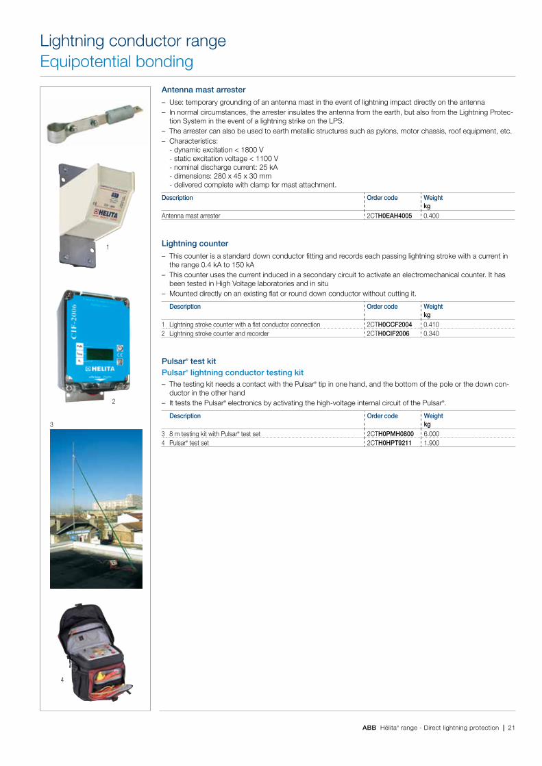
ABB Hélita® range - Direct lightning protection | 21
Antenna mast arrester
– Use: temporary grounding of an antenna mast in the event of lightning impact directly on the antenna – In normal circumstances, the arrester insulates the antenna from the earth, but also from the Lightning Protec-
tion System in the event of a lightning strike on the LPS. – The arrester can also be used to earth metallic structures such as pylons, motor chassis, roof equipment, etc. – Characteristics:
- dynamic excitation < 1800 V - static excitation voltage < 1100 V - nominal discharge current: 25 kA - dimensions: 280 x 45 x 30 mm - delivered complete with clamp for mast attachment.
Description Order code Weightkg
Antenna mast arrester 2CTH0EAH4005 0.400
Lightning counter
– This counter is a standard down conductor fitting and records each passing lightning stroke with a current in the range 0.4 kA to 150 kA
– This counter uses the current induced in a secondary circuit to activate an electromechanical counter. It has been tested in High Voltage laboratories and in situ
– Mounted directly on an existing flat or round down conductor without cutting it.
Description Order code Weightkg
1 Lightning stroke counter with a flat conductor connection 2CTH0CCF2004 0.4102 Lightning stroke counter and recorder 2CTH0CIF2006 0.340
Pulsar® test kitPulsar® lightning conductor testing kit – The testing kit needs a contact with the Pulsar® tip in one hand, and the bottom of the pole or the down con-
ductor in the other hand – It tests the Pulsar® electronics by activating the high-voltage internal circuit of the Pulsar®.
Description Order code Weightkg
3 8 m testing kit with Pulsar® test set 2CTH0PMH0800 6.0004 Pulsar® test set 2CTH0HPT9211 1.900
Lightning conductor rangeEquipotential bonding
1
2
3
4
22 | ABB Hélita® range - Direct lightning protection
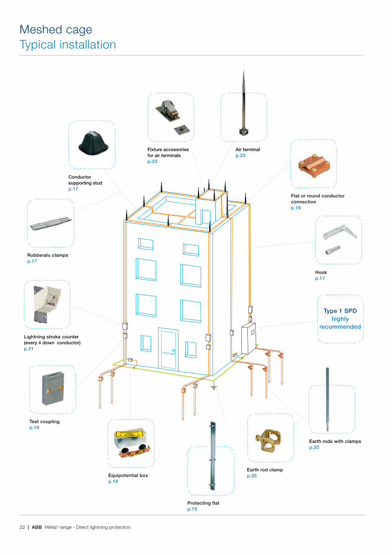
Meshed cageTypical installation
Flat or round conductor connectionp.16
Hookp.17
Test couplingp.18
Equipotential boxp.18
Lightning stroke counter (every 4 down conductor)p.21
Conductor supporting studp.17
Fixture accessories for air terminalsp.23
Air terminalp.23
Rubberalu clampsp.17
Protecting flatp.19
Earth rods with clampsp.20
Type 1 SPD highly
recommended
Earth rod clampp.20
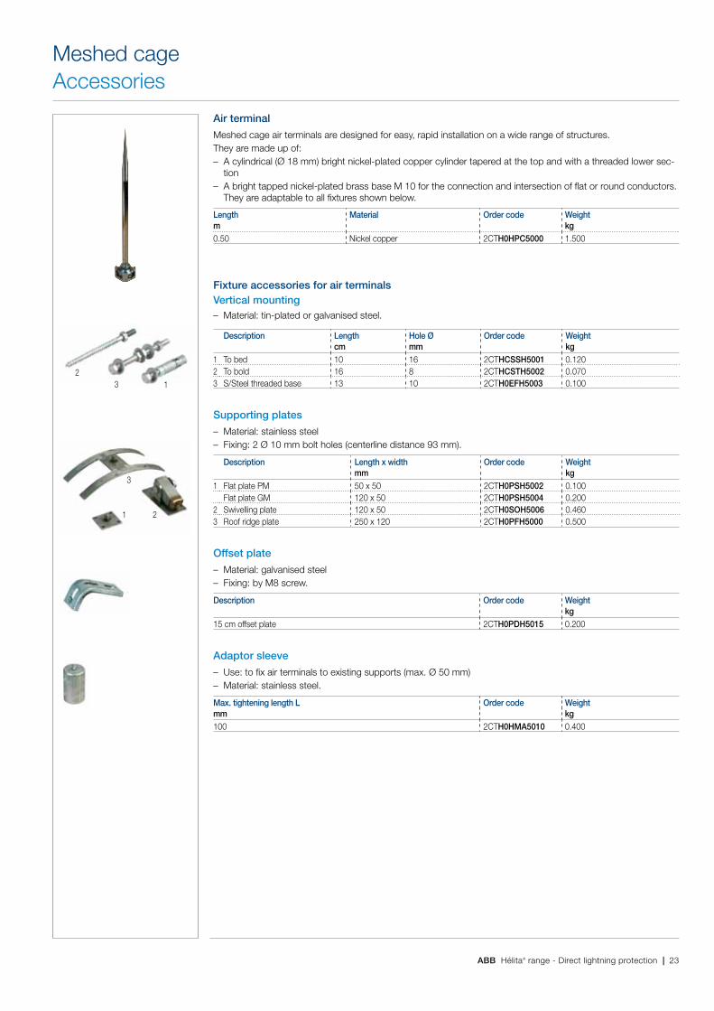
ABB Hélita® range - Direct lightning protection | 23
Air terminal
Meshed cage air terminals are designed for easy, rapid installation on a wide range of structures.They are made up of: – A cylindrical (ø 18 mm) bright nickel-plated copper cylinder tapered at the top and with a threaded lower sec-
tion – A bright tapped nickel-plated brass base M 10 for the connection and intersection of flat or round conductors.
They are adaptable to all fixtures shown below.
Length Material Order code Weightm kg0.50 Nickel copper 2CTH0HPC5000 1.500
Fixture accessories for air terminalsVertical mounting – Material: tin-plated or galvanised steel.
Description Length Hole Ø Order code Weightcm mm kg
1 To bed 10 16 2CTHCSSH5001 0.1202 To bold 16 8 2CTHCSTH5002 0.0703 S/Steel threaded base 13 10 2CTH0EFH5003 0.100
Supporting plates
– Material: stainless steel – Fixing: 2 ø 10 mm bolt holes (centerline distance 93 mm).
Description Length x width Order code Weightmm kg
1 Flat plate PM 50 x 50 2CTH0PSH5002 0.100Flat plate GM 120 x 50 2CTH0PSH5004 0.200
2 Swivelling plate 120 x 50 2CTH0SOH5006 0.4603 Roof ridge plate 250 x 120 2CTH0PFH5000 0.500
Offset plate
– Material: galvanised steel – Fixing: by M8 screw.
Description Order code Weightkg
15 cm offset plate 2CTH0PDH5015 0.200
Adaptor sleeve
– Use: to fix air terminals to existing supports (max. ø 50 mm) – Material: stainless steel.
Max. tightening length L Order code Weightmm kg100 2CTH0HMA5010 0.400
Meshed cageAccessories
1 2
3
132

IndexOrder code
Order code Page Order code Page Order code Page
24 | ABB Hélita® range - Direct lightning protection
2CTH0BLH2707 18
2CTH0BRC2780 16
2CTH0BRC2781 16
2CTH0BRH2779 16
2CTH0BRI2779 16
2CTH0BRX3780 16
2CTH0CCF2004 21
2CTH0CIF2006 21
2CTH0CRH4020 19
2CTH0EAH4005 21
2CTH0EFH5003 23
2CTH0HAR2445 17
2CTH0HAR2745 17
2CTH0HBI2703 17
2CTH0HBR2717 17
2CTH0HCB4240 17
2CTH0HCC2696 17
2CTH0HCC4000 15
2CTH0HCC5000 15
2CTH0HCM2704 17
2CTH0HCP2651 15
2CTH0HEF2107 13
2CTH0HEF2313 13
2CTH0HFC4002 15
2CTH0HKH0025 14
2CTH0HMA5010 23
2CTH0HPC5000 23
2CTH0HPF1001 10
2CTH0HPF2001 10
2CTH0HPP4523 13
2CTH0HPS2704 15
2CTH0HPS2705 15
2CTH0HPS2706 15
2CTH0HPS2708 15
2CTH0HPS2710 15
2CTH0HPS2844 15
2CTH0HPS2845 15
2CTH0HPS2846 15
2CTH0HPS2848 15
2CTH0HPT9211 21
2CTH0HRI3502 12
2CTH0HRI3503 12
2CTH0HRI4202 12
2CTH0HRI4203 12
2CTH0HRI4204 12
2CTH0HRI4206 12
2CTH0HRI5002 12
2CTH0HRI5003 12
2CTH0HRI5006 12
2CTH0HRP2705 17
2CTH0HST2044 13
2CTH0IMH3012 9
2CTH0IMH3013 9
2CTH0IMH4512 9
2CTH0IMH4513 9
2CTH0IMH6012 9
2CTH0IMH6013 9
2CTH0JCH2708 18
2CTH0PCS1920 19
2CTH0PDH5015 23
2CTH0PFH5000 23
2CTH0PMH0800 21
2CTH0PSH2009 18
2CTH0PSH5002 23
2CTH0PSH5004 23
2CTH0RPO2840 19
2CTH0RVH3071 18
2CTH0RVH3072 18
2CTH0RVH3073 18
2CTH0RVH3074 18
2CTH0SOH5006 23
2CTH0STP5030 16
2CTH0STP5050 16
2CTH0STP5075 16
2CTH0STP5100 16
2CTH0TPH2705 18
2CTH0TPH2768 18
2CTHCACA2025 20
2CTHCACA6460 20
2CTHCACA9500 20
2CTHCBMA0019 19
2CTHCBRP2680 16
2CTHCCPC2712 16
2CTHCCPI2711 16
2CTHCCRC8000 16
2CTHCCRE2700 13
2CTHCFOH2100 14
2CTHCFOH2101 14
2CTHCFOH2201 14
2CTHCGMD1020 20
2CTHCGMD6692 20
2CTHCHCI2419 17
2CTHCHCI2420 17
2CTHCHCI2421 17
2CTHCHCO0071 14
2CTHCHCO0752 14
2CTHCHFP2650 15
2CTHCHPA0109 14
2CTHCHPA0112 14
2CTHCHPA0115 14
2CTHCHPA0118 14
2CTHCHPA0209 14
2CTHCHPA0212 14
2CTHCHPA0215 14
2CTHCHPA0218 14
2CTHCHPA0309 14
2CTHCHPA0312 14
2CTHCHPA0315 14
2CTHCHPA0318 14
2CTHCHPA0409 14
2CTHCHPA0412 14
2CTHCHPA0415 14
2CTHCHPA0418 14
2CTHCHPB2772 17
2CTHCHPH0900 14
2CTHCHPH1200 14
2CTHCHPH1500 14
2CTHCHPH1800 14
2CTHCHPV2771 17
2CTHCPCS1920 20
2CTHCPRC8000 16
2CTHCPVB2010 19
2CTHCSSH5001 23
2CTHCSTH5002 23
2CTHCTLB5002 13
2CTHCTLB5004 13
2CTHCTLB5005 13
2CTHCTSH4525 13
hélita® rangePulsar® lightning conductors
1TXH 000 084 B0201_Pulsar-Lightning-Protection_Version ABB.indd 1 17/01/2011 09:22:01
hélita® rangePulsar® lightning conductors
1TXH 000 084 B0201
Other documentation

1TX
H 0
00 0
44 C
0201
- P
rinte
d in
Fra
nce
(Y+
V 0
1.20
11 L
amaz
ière
)
Contact us
NoteWe reserve the right to make technical changes or modify the contents of this document without prior notice. With regard to purchase orders, the agreed particulars shall prevail. ABB does not accept any responsibility whatsoever for potential errors or possible lack of information in this document.
We reserve all rights in this document and in the subject matter and illustrations contained therein. Any reproduction, disclosure to third parties or utilization of its contents – in whole or in parts – is forbidden without prior written consent of ABB.
Copyright© 2011 ABBAll rights reserved
ABB FranceLow Voltage Products DivisionPôle Foudre Soulé & Hélita1, avenue des Victimes du 11 juin 194465203 Bagnères de Bigorre - FranceTel: +33 (0)5 62 91 45 60Fax: +33 (0)5 62 91 45 62
www.abb.com