Embed Size (px)
Citation preview
Mahendra Sponge and Power Limited [Expansion of Steel plant]
Plot No.: 76 & 77, Phase # 2,
Industrial Growth Center, Siltara,
Raipur District, Chhattisgarh
PRE-FEASIBILITY REPORT
Expansion of Steel Plant Pre-feasibility Report
1
Chapter - 1
EXECUTIVE SUMMARY
1.1 ABOUT PROJECT PROPONENT
Mahendra Sponge & Power Ltd. [here in after referred as MSPL] company is in steel
business and having good reputation in the market, which was gained with good business
experience. Looking forward in prospects of Steel sector, MSPL propose to go for expansion
of steel plant in Raipur District of Chhattisgarh State.
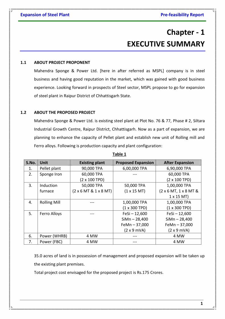
1.2 ABOUT THE PROPOSED PROJECT
Mahendra Sponge & Power Ltd. is existing steel plant at Plot No. 76 & 77, Phase # 2, Siltara
Industrial Growth Centre, Raipur District, Chhattisgarh. Now as a part of expansion, we are
planning to enhance the capacity of Pellet plant and establish new unit of Rolling mill and
Ferro alloys. Following is production capacity and plant configuration:
Table 1
S.No. Unit Existing plant Proposed Expansion After Expansion
1. Pellet plant 90,000 TPA 6,00,000 TPA 6,90,000 TPA
2. Sponge Iron 60,000 TPA (2 x 100 TPD)
--- 60,000 TPA (2 x 100 TPD)
3. Induction furnace
50,000 TPA (2 x 6 MT & 1 x 8 MT)
50,000 TPA (1 x 15 MT)
1,00,000 TPA (2 x 6 MT, 1 x 8 MT &
1 x 15 MT)
4. Rolling Mill --- 1,00,000 TPA (1 x 300 TPD)
1,00,000 TPA (1 x 300 TPD)
5. Ferro Alloys --- FeSi – 12,600 SiMn – 28,400 FeMn – 37,000
(2 x 9 mVA)
FeSi – 12,600 SiMn – 28,400 FeMn – 37,000
(2 x 9 mVA)
6. Power (WHRB) 4 MW --- 4 MW
7. Power (FBC) 4 MW --- 4 MW
35.0 acres of land is in possession of management and proposed expansion will be taken up
the existing plant premises.
Total project cost envisaged for the proposed project is Rs.175 Crores.
Expansion of Steel Plant Pre-feasibility Report
2
Chapter - 2 INTRODUCTION OF THE PROJECT / BACKGROUND INFORMATION
2.1 IDENTIFICATION OF PROJECT AND PROJECT PROPONENT
Mahendra Sponge & Power Ltd. [here in after referred as MSPL] company is engaged in
steel business and having good reputation in the market, which was gained with good
business experience. Looking forward in prospects of Steel sector, MSPL propose to go for
expansion of steel plant in Raipur District of Chhattisgarh State.
2.2 BRIEF DESCRIPTION OF NATURE OF PRODUCT
The company after assessing the market potential of the steel industry thoroughly decided
to go in for iron-ore pellets. The highly encouraging response received on market survey
also ruled favorably for the said project. Promoters are well experienced entrepreneurs
and are well supported by technical personnel experience to run such unit.
Presently, most of the coal based sponge iron plants in India uses iron ore lumps. The
requirement is generally 1.8 t/ t of sponge iron. This high requirement is mainly due to the
fines generated in handling the purchased ore from the source to the plant. This reduces
the kiln campaign length and increases ore fines lost.
Use of pellets with better physical and metallurgical properties for sponge iron production
reduces the accretion formation in the kiln and the pellets consumption is about1.6 t/t.
Further, the production from the kiln is expected to increase by 25% to 30%.
In view of the above, Mahendra Sponge & Power Ltd. proposed to go for expansion of
pellet plant in the existing steel plant at Plot No. 76 & 77, Phase # 2, Siltara Industrial
Growth Centre, Raipur District, Chhattisgarh.
2.3 NEED FOR THE PROJECT AND IMPORTANCE TO THE REGION
Utilization of low grade ore and fines has to play an important role. In India partly due to
the sponge iron sector; the overall percentage of lumps usage in steel making (47%) is
higher than most other countries. As hard ore reserves is depleting day by day, lump
generation suitable for blast furnace operation is coming down resulting in production of
large amount of surplus fines. Alternative iron making processes for production of steel
may lead to changing pattern of use material inputs and feed stock causing significant shift
Expansion of Steel Plant Pre-feasibility Report
3
in respective share of lumps and agglomerated iron ore (pellets) and will also enable the
use of ores which could not be utilized earlier. As fines forms considerable part of iron ore
resources, value addition to the iron ore fines through various activities such as
beneficiation, Pelletization is the need of the hour.
2.4 DEMAND – SUPPLY GAP
With the rapid development of Infrastructure and manufacturing sector, the Iron and steel
industry is poised for an accelerated growth. Steel demand in the country is increasing at
an average rate of 10% and is likely to remain in 10-12% range at least for the next
decade. In order to meet the steadily growing steel demand in the country, domestic steel
producing capacity is required to be higher than 110 mtpa within next three years and,
150 mtpa by the year 2016-17. Indian economy is growing at more than 10% rate, steel
demand and supply will grow in the same way. As good quality iron ore deposits are
depleting fast beneficiation technologies will have to be adopted to meet iron ore
demand. Therefore good yield of beneficiation process generally around 70 % will make
this technology economically viable.
Agglomeration technologies such as Pelletization will have to be added to DRI Plant
/ Steel Plant so that concentrates can be used as feed material. Recycling of
cheaper raw material (fines) by beneficiation and pelletization process as feed
material will result in better Return on Investment as compared to using Iron ore
as feed material.
With superior reducibility behavior of pellets compared to lump ore efficiency of
DRI production improves.
It can be concluded from results obtained by conducting various tests on
manufactured pavement blocks that substitution of iron ore tailings for sand or
quarry dust shows better compressive strength without much change in water
absorption.
In the Indian context, by the year 2020, India’s production of steel is expected to touch110
Million Tonnes and it is imperative that the fines generated in the mining of iron ore be
utilized for the production of steel. The Indian steel industry which predominantly uses
expensive lump ore is gradually moving towards usage of iron ore pellets.
Expansion of Steel Plant Pre-feasibility Report
4
The present Indian raw material scenario offers an opportunistic disposition towards
pellet making owing to the availability of large quantities of sub grade fines, slimes and
blue dust etc. at different mine heads. These materials are not suitable for sinter making.
Pelletization is the only possible route for salvaging these, otherwise waste but valuable
materials. Recent techno-economic studies indicated favorable indices for installation of
pellet plants, both small and large scale. The demand supply analysis also underlines the
need for Pelletization.
2.6 EMPLOYMENT GENERATION (DIRECT & INDIRECT)
PHYSICAL INFRASTRUCTURE
Once the proposed activity is commissioned, the socio-economic status of the local people
will improve and there by infrastructure facilities like communication systems will
improve. Most of the villages at present do not have protected water supply. After the
implementation of the project, the affordability of the public to spend on water
treatment, supply & distribution will more along with the aid from the state government.
EMPLOYMENT POTENTIAL
The proposed project creates employment to 100 people during construction and 50
people during operation of the proposed expansion.
SKILLED
Total skilled employment in the proposed plant will be around 15.
SEMI-SKILLED
Total Semi-skilled employment in the proposed project will be around 15. Priority will be
given to local people for semi-skilled jobs.
UNSKILLED
Total Unskilled employment in the proposed project will be around 20. Top priority will be
given to local people for unskilled jobs.
Expansion of Steel Plant Pre-feasibility Report
5
Chapter - 3
PROJECT DESCRIPTION
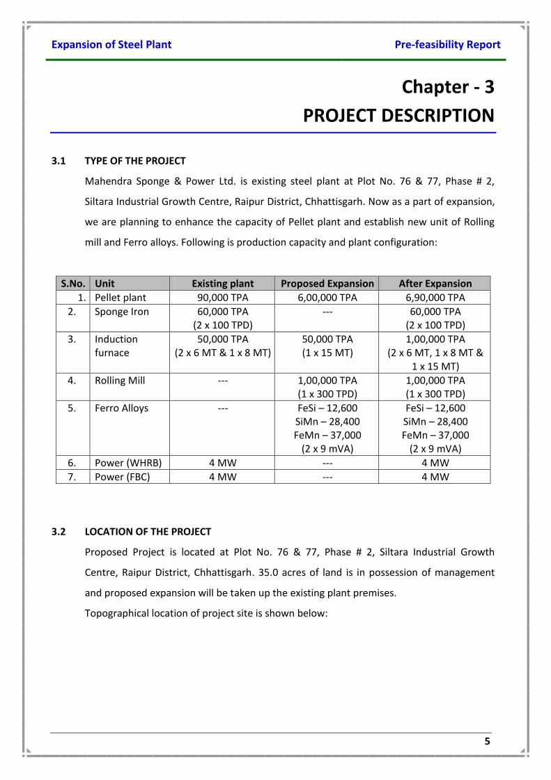
3.1 TYPE OF THE PROJECT
Mahendra Sponge & Power Ltd. is existing steel plant at Plot No. 76 & 77, Phase # 2,
Siltara Industrial Growth Centre, Raipur District, Chhattisgarh. Now as a part of expansion,
we are planning to enhance the capacity of Pellet plant and establish new unit of Rolling
mill and Ferro alloys. Following is production capacity and plant configuration:
S.No. Unit Existing plant Proposed Expansion After Expansion
1. Pellet plant 90,000 TPA 6,00,000 TPA 6,90,000 TPA
2. Sponge Iron 60,000 TPA (2 x 100 TPD)
--- 60,000 TPA (2 x 100 TPD)
3. Induction furnace
50,000 TPA (2 x 6 MT & 1 x 8 MT)
50,000 TPA (1 x 15 MT)
1,00,000 TPA (2 x 6 MT, 1 x 8 MT &
1 x 15 MT)
4. Rolling Mill --- 1,00,000 TPA (1 x 300 TPD)
1,00,000 TPA (1 x 300 TPD)
5. Ferro Alloys --- FeSi – 12,600 SiMn – 28,400 FeMn – 37,000
(2 x 9 mVA)
FeSi – 12,600 SiMn – 28,400 FeMn – 37,000
(2 x 9 mVA)
6. Power (WHRB) 4 MW --- 4 MW
7. Power (FBC) 4 MW --- 4 MW
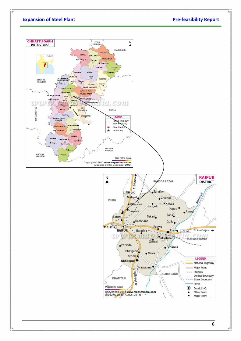
3.2 LOCATION OF THE PROJECT
Proposed Project is located at Plot No. 76 & 77, Phase # 2, Siltara Industrial Growth
Centre, Raipur District, Chhattisgarh. 35.0 acres of land is in possession of management
and proposed expansion will be taken up the existing plant premises.
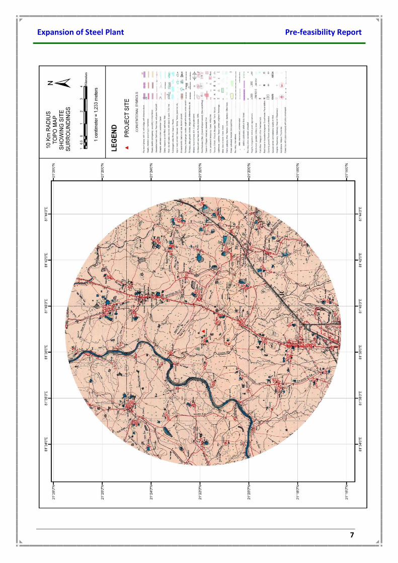
Topographical location of project site is shown below:
Expansion of Steel Plant Pre-feasibility Report
6
Expansion of Steel Plant Pre-feasibility Report
7
Expansion of Steel Plant Pre-feasibility Report
8
3.3 DETAILS OF THE ALTERNATE SITES
No alternative site have been considered as proposed expansion will be taken up in the
existing plant premises.
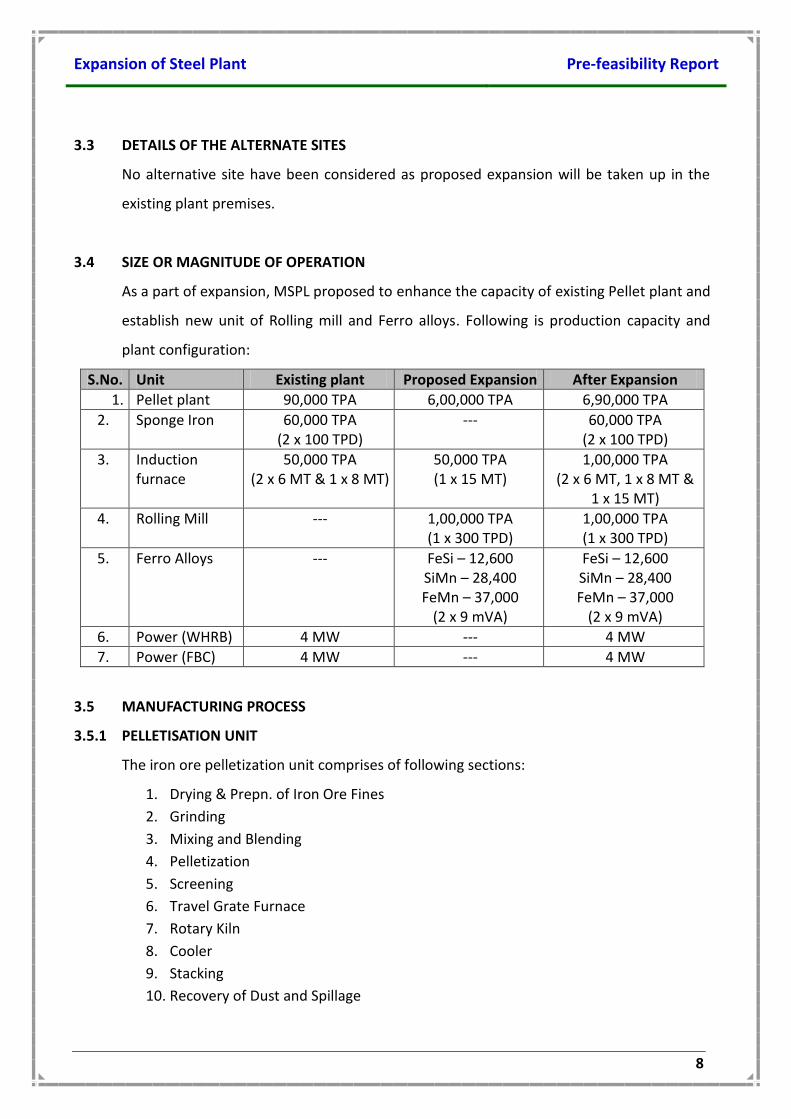
3.4 SIZE OR MAGNITUDE OF OPERATION
As a part of expansion, MSPL proposed to enhance the capacity of existing Pellet plant and
establish new unit of Rolling mill and Ferro alloys. Following is production capacity and
plant configuration:
S.No. Unit Existing plant Proposed Expansion After Expansion
1. Pellet plant 90,000 TPA 6,00,000 TPA 6,90,000 TPA
2. Sponge Iron 60,000 TPA (2 x 100 TPD)
--- 60,000 TPA (2 x 100 TPD)
3. Induction furnace
50,000 TPA (2 x 6 MT & 1 x 8 MT)
50,000 TPA (1 x 15 MT)
1,00,000 TPA (2 x 6 MT, 1 x 8 MT &
1 x 15 MT)
4. Rolling Mill --- 1,00,000 TPA (1 x 300 TPD)
1,00,000 TPA (1 x 300 TPD)
5. Ferro Alloys --- FeSi – 12,600 SiMn – 28,400 FeMn – 37,000
(2 x 9 mVA)
FeSi – 12,600 SiMn – 28,400 FeMn – 37,000
(2 x 9 mVA)
6. Power (WHRB) 4 MW --- 4 MW
7. Power (FBC) 4 MW --- 4 MW
3.5 MANUFACTURING PROCESS
3.5.1 PELLETISATION UNIT
The iron ore pelletization unit comprises of following sections:
1. Drying & Prepn. of Iron Ore Fines
2. Grinding
3. Mixing and Blending
4. Pelletization
5. Screening
6. Travel Grate Furnace
7. Rotary Kiln
8. Cooler
9. Stacking
10. Recovery of Dust and Spillage
Expansion of Steel Plant Pre-feasibility Report
9
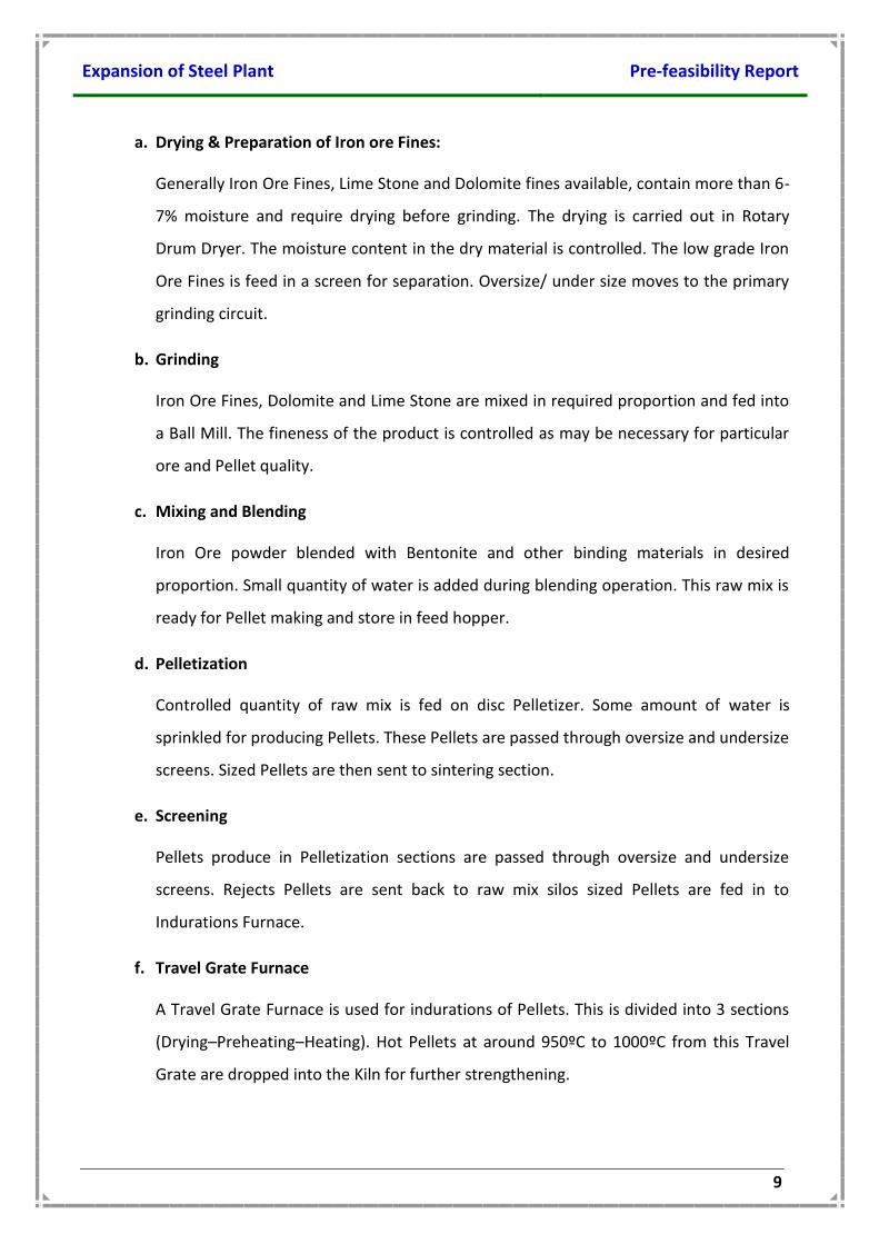
a. Drying & Preparation of Iron ore Fines:
Generally Iron Ore Fines, Lime Stone and Dolomite fines available, contain more than 6-
7% moisture and require drying before grinding. The drying is carried out in Rotary
Drum Dryer. The moisture content in the dry material is controlled. The low grade Iron
Ore Fines is feed in a screen for separation. Oversize/ under size moves to the primary
grinding circuit.
b. Grinding
Iron Ore Fines, Dolomite and Lime Stone are mixed in required proportion and fed into
a Ball Mill. The fineness of the product is controlled as may be necessary for particular
ore and Pellet quality.
c. Mixing and Blending
Iron Ore powder blended with Bentonite and other binding materials in desired
proportion. Small quantity of water is added during blending operation. This raw mix is
ready for Pellet making and store in feed hopper.
d. Pelletization
Controlled quantity of raw mix is fed on disc Pelletizer. Some amount of water is
sprinkled for producing Pellets. These Pellets are passed through oversize and undersize
screens. Sized Pellets are then sent to sintering section.
e. Screening
Pellets produce in Pelletization sections are passed through oversize and undersize
screens. Rejects Pellets are sent back to raw mix silos sized Pellets are fed in to
Indurations Furnace.
f. Travel Grate Furnace
A Travel Grate Furnace is used for indurations of Pellets. This is divided into 3 sections
(Drying–Preheating–Heating). Hot Pellets at around 950ºC to 1000ºC from this Travel
Grate are dropped into the Kiln for further strengthening.
Expansion of Steel Plant Pre-feasibility Report
10
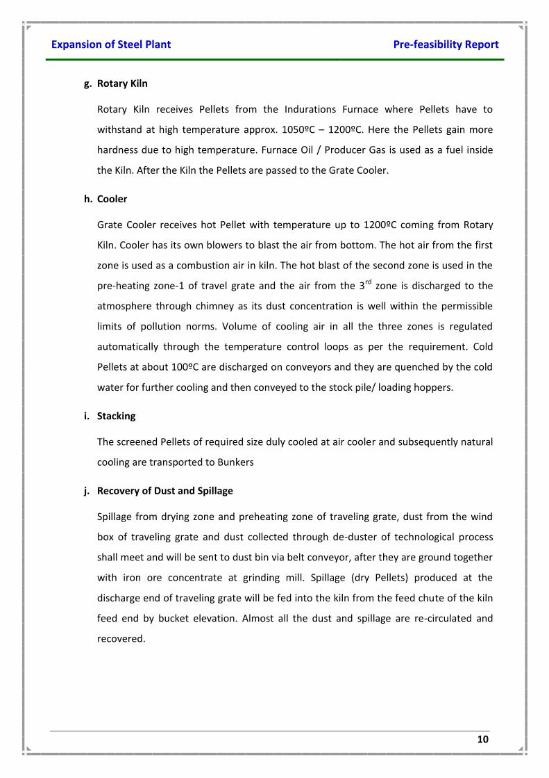
g. Rotary Kiln
Rotary Kiln receives Pellets from the Indurations Furnace where Pellets have to
withstand at high temperature approx. 1050ºC – 1200ºC. Here the Pellets gain more
hardness due to high temperature. Furnace Oil / Producer Gas is used as a fuel inside
the Kiln. After the Kiln the Pellets are passed to the Grate Cooler.
h. Cooler
Grate Cooler receives hot Pellet with temperature up to 1200ºC coming from Rotary
Kiln. Cooler has its own blowers to blast the air from bottom. The hot air from the first
zone is used as a combustion air in kiln. The hot blast of the second zone is used in the
pre-heating zone-1 of travel grate and the air from the 3rd zone is discharged to the
atmosphere through chimney as its dust concentration is well within the permissible
limits of pollution norms. Volume of cooling air in all the three zones is regulated
automatically through the temperature control loops as per the requirement. Cold
Pellets at about 100ºC are discharged on conveyors and they are quenched by the cold
water for further cooling and then conveyed to the stock pile/ loading hoppers.
i. Stacking
The screened Pellets of required size duly cooled at air cooler and subsequently natural
cooling are transported to Bunkers
j. Recovery of Dust and Spillage
Spillage from drying zone and preheating zone of traveling grate, dust from the wind
box of traveling grate and dust collected through de-duster of technological process
shall meet and will be sent to dust bin via belt conveyor, after they are ground together
with iron ore concentrate at grinding mill. Spillage (dry Pellets) produced at the
discharge end of traveling grate will be fed into the kiln from the feed chute of the kiln
feed end by bucket elevation. Almost all the dust and spillage are re-circulated and
recovered.
Expansion of Steel Plant Pre-feasibility Report
11
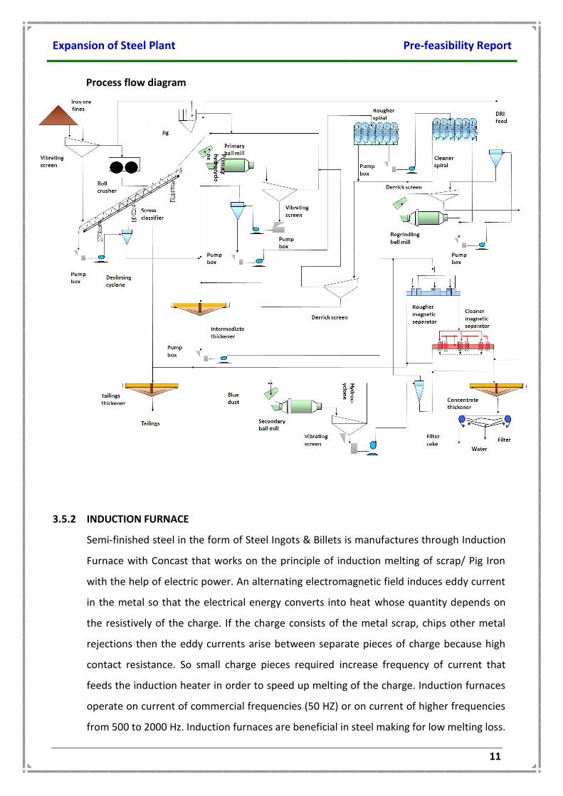
Process flow diagram
3.5.2 INDUCTION FURNACE
Semi-finished steel in the form of Steel Ingots & Billets is manufactures through Induction
Furnace with Concast that works on the principle of induction melting of scrap/ Pig Iron
with the help of electric power. An alternating electromagnetic field induces eddy current
in the metal so that the electrical energy converts into heat whose quantity depends on
the resistively of the charge. If the charge consists of the metal scrap, chips other metal
rejections then the eddy currents arise between separate pieces of charge because high
contact resistance. So small charge pieces required increase frequency of current that
feeds the induction heater in order to speed up melting of the charge. Induction furnaces
operate on current of commercial frequencies (50 HZ) or on current of higher frequencies
from 500 to 2000 Hz. Induction furnaces are beneficial in steel making for low melting loss.
Expansion of Steel Plant Pre-feasibility Report
12
An Induction furnace constitutes a single larger primary coil made of water- cooled copper
tube. The working voltage impressed across the terminals of the coil. These furnaces have
a great much application for melting of iron, Steel and Nonferrous. This type of furnace
has a rammed lining. The ramming matenal silica mass contains should more then 96%
silica and minimum of Al2O3 & Fe2O3. Before ramming the material a steel template kept
inside the furnace and rammed the material between the template and the insulated coil
of the induction heater. To minimize the consumption of electric power and cut down the
melting period the crucible wall must be as thin as possible. During running the furnace
one must keep watch on the state of lining because it operates under most unfavorable
condition. The inside of crucible lining is in contact with liquid metal while its outside
surface contacts the water-cooled induction.
Charging: -
The pieces of scrap should be kept on the bottom gently to avoiding impacts into a
compact heap. The scrap pieces / Pig Iron should be in small size that provide good
compacting of the batch without leaving spacing between the charge and crucible wall.
This offer an advantage of quick melting of the charge with a minimum power spent in the
stage for the heat.
The zone of a highest temperature during the meet lies in the power part of the crucible
therefore it is practical to place first high melting scrap on the crucible bottom. Large and
high melting pieces should stand parallel and close to the crucible was while low melting
components should be in the middle of the large crucible. Small capacity furnaces are
loaded manually and the large capacity furnaces with the aid of buckets.
Melting: -
At the beginning of the melting the furnace works for 5 to 10 minutes on low power until
the surge of current fed from the generator disappear. The furnace power is then brought
up to a maximum. The charge melts with the crucible held closed. When the charge
approaches the fluid stages then the solid pieces are pressed backed with a crow bar. The
furnaces is then loaded to its capacity by adding small size of scrap as soon as the charge
melted, the stag is formed to protect the metal from oxidation and to avoid reduce the
melting loss. If the slag generate in excess it should be skimmed off periodically, at the last
to deoxidized the metal with Ferromanganese, Silico-manganese and Ferro-silicon. Now
the metal is ready tap for either in ingot or billet casting.
Expansion of Steel Plant Pre-feasibility Report
13
Casting in Ingot mould: -
For casting ingot the metal temperature should be around 1560ºC/ 1570 ºC in ladle. Liquid
metal tap from furnace to ladle by the help of crane then the ladle in the centered on the
trumpet metal flows from the ladle bottom and filled the ingot mould. Thus the ingot is
ready.
Casting in B.C.M: -
Steel for making billet, the temperature of liquid metal from furnace to ladle, the final
metal temperature in ladle should be 80ºC. superheat from liquidious. Liquid metal is
storage in tundish through ladle then the tundish metal passes from the various section of
mould jacket that is as per requirement (100 X 100 mm, 125 X 125 mm, 160 X 160 mm,
200 X 200 mm) this is a continuous process, length of billet of is cut as par requirement.
Process flow chart is enclosed.
PLANT FACILITIES FOR CONTINUOUS CASTING MACHINE
Billet caster:
The billet caster shall be complete with ladle stand, mould assembly, strand guide
segments and supports withdrawal and straightening system, mould cooling system, Cut
off equipment including length measuring device, Marking machine etc. Requisite dummy
bar and facilities for Dummy bar disconnecting and a dummy bar receiver will be included.
Auxiliary equipment :
The auxiliary facilities required for the Billet caster will be included. This will include
operating platform, cooling bed, ventilation system for spray chambers, equipment for
collection and disposal of crop-ends, Repair and assembly facilities for moulds, and
segments, Tundishes, Tundish preparation facilities including tundish drying station,
Hydraulic system and Centralized lubrication system, scale handling system.
Electrical Equipment:
The electrical equipment for the caster will include the drives, HT switchgear, LT
switchgear, control desks, cabling and accessories.
Instrumental and automation:
A modern DCS process automation system shall be provided for control of process
function, sequencing and interlocking and to execute safely controls. Specific features
shall include mould level control, computer aided quality control, and process field
Expansion of Steel Plant Pre-feasibility Report
14
instruments comprising measuring units, transmitters, load cells, actuators, Programmable
controllers and PCs ands communication system.
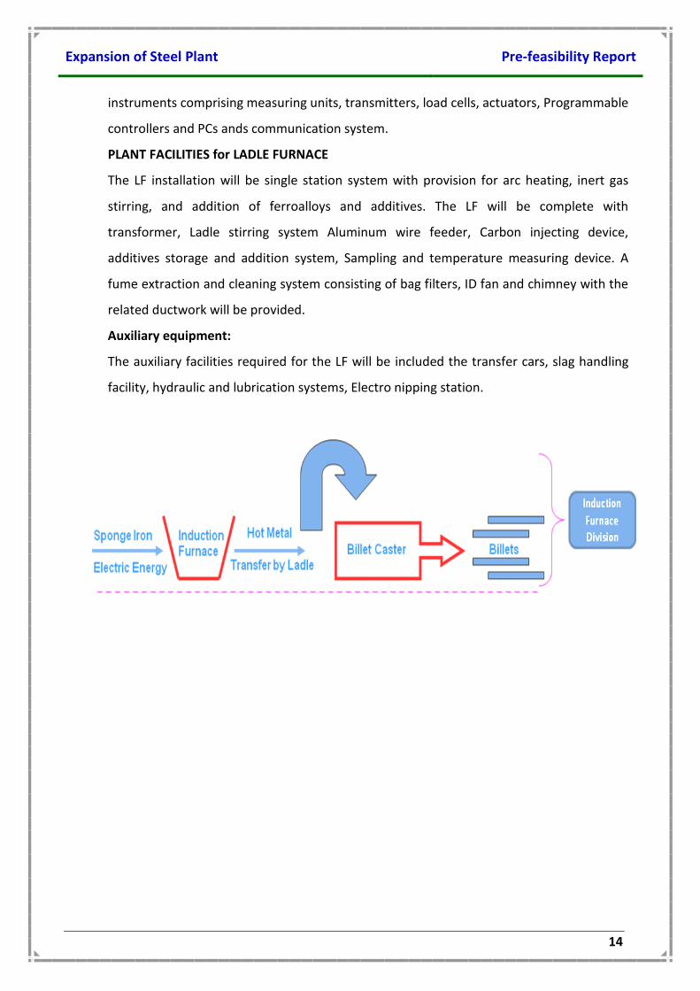
PLANT FACILITIES for LADLE FURNACE
The LF installation will be single station system with provision for arc heating, inert gas
stirring, and addition of ferroalloys and additives. The LF will be complete with
transformer, Ladle stirring system Aluminum wire feeder, Carbon injecting device,
additives storage and addition system, Sampling and temperature measuring device. A
fume extraction and cleaning system consisting of bag filters, ID fan and chimney with the
related ductwork will be provided.
Auxiliary equipment:
The auxiliary facilities required for the LF will be included the transfer cars, slag handling
facility, hydraulic and lubrication systems, Electro nipping station.
Expansion of Steel Plant Pre-feasibility Report
15
3.5.3 ROLLING MILL UNIT
Rolling mill unit comprise of Reheating furnace and Bar & round mill.
Reheating furnace
A pusher type furnace has been envisaged for the heating of billets. The furnace will be
end charging and side discharging. It will have single row as well as double row charging
facility. The furnace will be heated with FO. The furnace combustion system will comprise
of air blowers, FO storage, supply and preheating system and other associated facilities.
The product of combustion will leave the furnace at charging end and exhausted through
underground flue tunnel and passed through a metallic tubular recuperator before finally
let off to a self-supporting steel chimney of sufficient height. A set of instrument will be
used for smooth operation of the furnace.
Bar and round mill
A cross country type mill has been envisaged for the plant. The stands have been grouped
into roughing, intermediate and finishing groups. Roughing group will have 4 (four)
stands, intermediate group will have 8 (eight) stands and finishing mill will have 8 (eight)
stands. Roughing group of stands will be driven by one motor. 4 nos. of intermediate
stands will be driven by two motors and balance 4 nos. will be driven by a separate motor.
Each stand of finishing group will be driven by single motor. Necessary guides and troughs
will be provided at entry and exit of mill stands.
One wire rod out let has been provided in the mill. The wire rod line will have 4 stand
block driven by a single motor through gear box. Coil forming and handling of coil is
provided.
Automated tilting, drop type tilter and feeding arrangement will be provided in roughing
group of stands. Repeaters have been provided in roughing / intermediate stands as
necessary.
Design provision has been made for introduction of slit rolling facility in future to roll 8
mm, 10 mm & 12 mm rebars in two strands. The rebars discharged from the mill will pass
through a water cooling system comprising cooling pipes with high pressure water nozzles
for rapid water quenching. At the cooling pipes the bar skin temperature will be reduced
to about 600ºC. The core of the bar still remains hot. This entrapped heat tempers the
bar. This thermo-mechanical treatment of the bars increases tensile strength without
Expansion of Steel Plant Pre-feasibility Report
16
adversely effecting weldability and elongation properties. This process eliminates
requirement of cold twisting of bars for production of rebars.
A dividing shear, to cut the products to cooling bed length, will be located immediately
after the water cooling system. This shear will divide all products to cooling bed lengths.
Rake type cooling beds have been envisaged to receive the rolled product. Cooling bed
will be provided with incoming and outgoing roller tables. One cold shear has been
provided to cut the bars coming out of cooling bed into commercial length of 6 to 12 m.
The bar products will be formed into bundles and will be strapped by strapping machine
manually.
The finished products will be removed by overhead EOT crane and stored in the storage
area or dispatched through road vehicles.
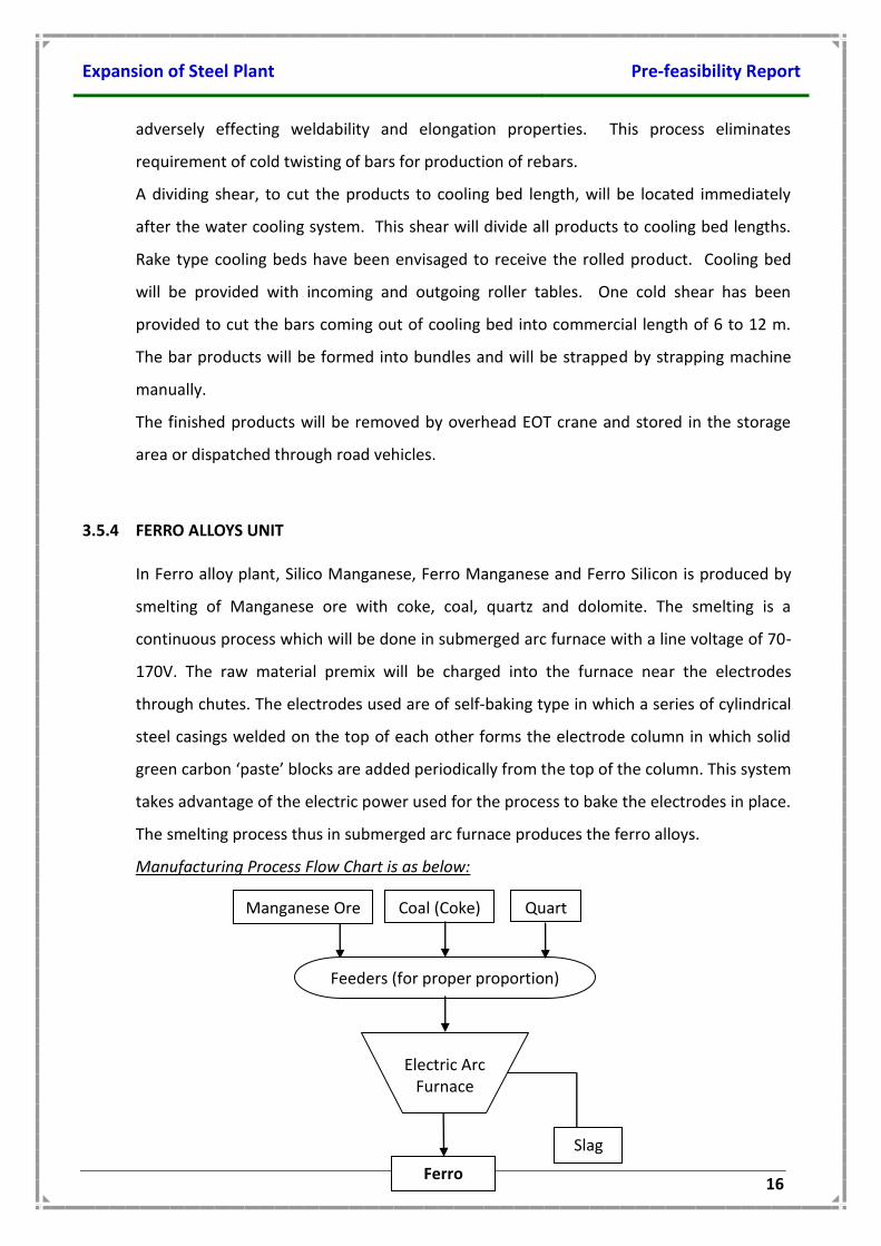
3.5.4 FERRO ALLOYS UNIT
In Ferro alloy plant, Silico Manganese, Ferro Manganese and Ferro Silicon is produced by
smelting of Manganese ore with coke, coal, quartz and dolomite. The smelting is a
continuous process which will be done in submerged arc furnace with a line voltage of 70-
170V. The raw material premix will be charged into the furnace near the electrodes
through chutes. The electrodes used are of self-baking type in which a series of cylindrical
steel casings welded on the top of each other forms the electrode column in which solid
green carbon ‘paste’ blocks are added periodically from the top of the column. This system
takes advantage of the electric power used for the process to bake the electrodes in place.
The smelting process thus in submerged arc furnace produces the ferro alloys.
Manufacturing Process Flow Chart is as below:
Electric Arc Furnace
Feeders (for proper proportion)
Quartz
Manganese Ore Coal (Coke)
Ferro Alloys
Slag
Expansion of Steel Plant Pre-feasibility Report
17
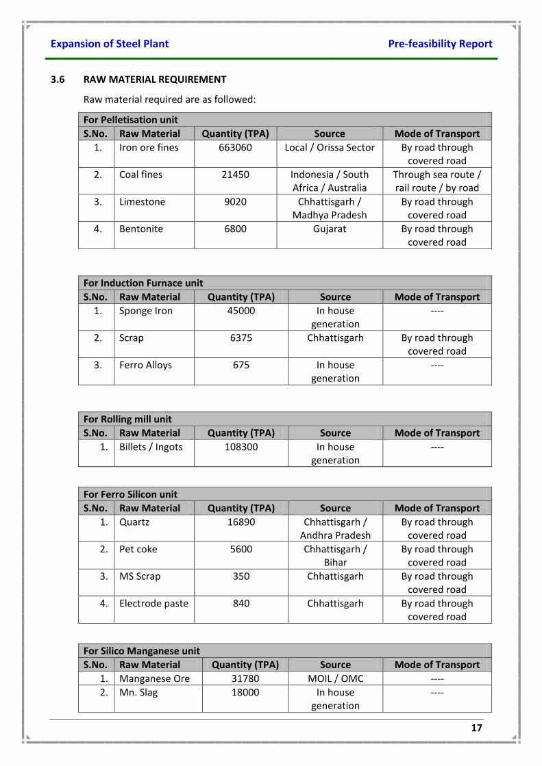
3.6 RAW MATERIAL REQUIREMENT
Raw material required are as followed:
For Pelletisation unit
S.No. Raw Material Quantity (TPA) Source Mode of Transport
1. Iron ore fines 663060 Local / Orissa Sector By road through covered road
2. Coal fines 21450 Indonesia / South Africa / Australia
Through sea route / rail route / by road
3. Limestone 9020 Chhattisgarh / Madhya Pradesh
By road through covered road
4. Bentonite 6800 Gujarat By road through covered road
For Induction Furnace unit
S.No. Raw Material Quantity (TPA) Source Mode of Transport
1. Sponge Iron 45000 In house generation
----
2. Scrap 6375 Chhattisgarh By road through covered road
3. Ferro Alloys 675 In house generation
----
For Rolling mill unit
S.No. Raw Material Quantity (TPA) Source Mode of Transport
1. Billets / Ingots 108300 In house generation
----
For Ferro Silicon unit
S.No. Raw Material Quantity (TPA) Source Mode of Transport
1. Quartz 16890 Chhattisgarh / Andhra Pradesh
By road through covered road
2. Pet coke 5600 Chhattisgarh / Bihar
By road through covered road
3. MS Scrap 350 Chhattisgarh By road through covered road
4. Electrode paste 840 Chhattisgarh By road through covered road
For Silico Manganese unit
S.No. Raw Material Quantity (TPA) Source Mode of Transport
1. Manganese Ore 31780 MOIL / OMC ----
2. Mn. Slag 18000 In house generation
----
Expansion of Steel Plant Pre-feasibility Report
18
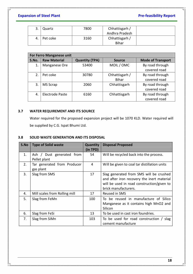
3. Quartz 7800 Chhattisgarh / Andhra Pradesh
4. Pet coke 3160 Chhattisgarh / Bihar
For Ferro Manganese unit
S.No. Raw Material Quantity (TPA) Source Mode of Transport
1. Manganese Ore 53400 MOIL / OMC By road through covered road
2. Pet coke 30780 Chhattisgarh / Bihar
By road through covered road
3. MS Scrap 2060 Chhattisgarh By road through covered road
4. Electrode Paste 6160 Chhattisgarh By road through covered road
3.7 WATER REQUIREMENT AND ITS SOURCE
Water required for the proposed expansion project will be 1070 KLD. Water required will
be supplied by C.G. Ispat Bhumi Ltd.
3.8 SOLID WASTE GENERATION AND ITS DISPOSAL
S.No Type of Solid waste Quantity (in TPD)
Disposal Proposed
1. Ash / Dust generated from Pellet plant
54 Will be recycled back into the process.
2. Tar generated from Producer gas plant
4 Will be given to coal tar distillation units
3. Slag from SMS 17 Slag generated from SMS will be crushed and after iron recovery the inert material will be used in road construction/given to brick manufacturers.
4. Mill scales from Rolling mill 17 Reused in SMS
5. Slag from FeMn 100 To be reused in manufacture of Silico Manganese as it contains high MnO2 and Silicon
6. Slag from FeSi 13 To be used in cast iron foundries.
7. Slag from SiMn 103 To be used for road construction / slag cement manufacture
Expansion of Steel Plant Pre-feasibility Report
19
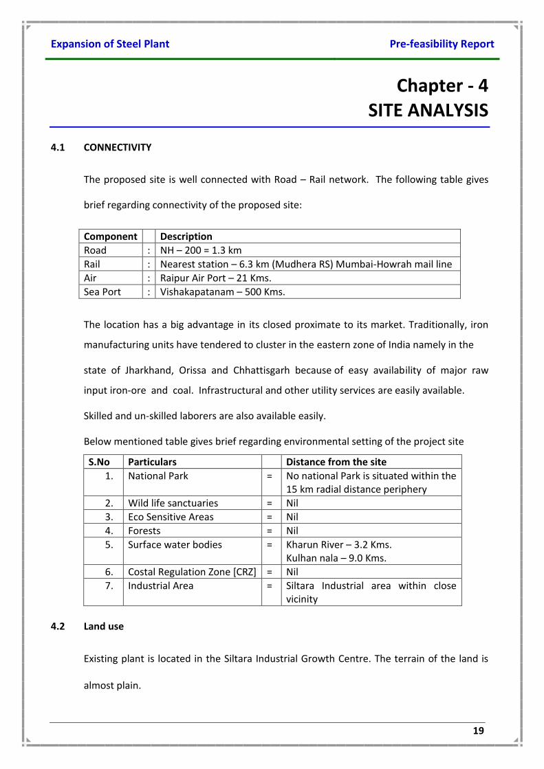
Chapter - 4 SITE ANALYSIS
4.1 CONNECTIVITY
The proposed site is well connected with Road – Rail network. The following table gives
brief regarding connectivity of the proposed site:
Component Description
Road : NH – 200 = 1.3 km
Rail : Nearest station – 6.3 km (Mudhera RS) Mumbai-Howrah mail line
Air : Raipur Air Port – 21 Kms.
Sea Port : Vishakapatanam – 500 Kms.
The location has a big advantage in its closed proximate to its market. Traditionally, iron
manufacturing units have tendered to cluster in the eastern zone of India namely in the
state of Jharkhand, Orissa and Chhattisgarh because of easy availability of major raw
input iron-ore and coal. Infrastructural and other utility services are easily available.
Skilled and un-skilled laborers are also available easily.
Below mentioned table gives brief regarding environmental setting of the project site
S.No Particulars Distance from the site
1. National Park = No national Park is situated within the 15 km radial distance periphery
2. Wild life sanctuaries = Nil
3. Eco Sensitive Areas = Nil
4. Forests = Nil
5. Surface water bodies = Kharun River – 3.2 Kms. Kulhan nala – 9.0 Kms.
6. Costal Regulation Zone [CRZ] = Nil
7. Industrial Area = Siltara Industrial area within close vicinity
4.2 Land use
Existing plant is located in the Siltara Industrial Growth Centre. The terrain of the land is
almost plain.
Expansion of Steel Plant Pre-feasibility Report
20
4.3 Topography
The topography of the land is flat without undulations.
4.4 Existing land use pattern
MSPL is an existing plant situated in Siltara Industrial Growth Centre. Land is converted for
Industrial purpose. 35.0 acres of land is in possession of management and proposed
expansion will be taken up in the existing plant premises.
There are no ecologically sensitive places like national park, sanctuary, biosphere
reserve, reserve forest etc. around 10 Kms. radius of the site. There is no route of
migratory animals within the project site. The site satisfies the criteria stipulated by the
Ministry of Environment & Forest, Government of India for setting up of industries.
4.4 Existing infrastructure
Water supply in most of the villages is available. Inter-village transport facility is available
only for the selected villages. While educational facilities & health facilities are not
encouraging in most of the villages. There is well established road connection.
4.5 Climatic data from secondary sources
Raipur has a tropical wet and dry climate, temperatures remain moderate throughout the
year, except from March to June, which can be extremely hot. The temperature in April–
May sometimes rises above 48 °C (118 °F).These summer months also have dry and hot
winds. In summers, the temperature can also go up to 50 °C. The city receives about 1,300
millimetres (51 in) of rain, mostly in the monsoon season from late June to early October.
Winters last from November to January and are mild, although lows can fall to 5 °C (41 °F).
Expansion of Steel Plant Pre-feasibility Report
21
Chapter - 5 PLANNING BRIEF
5.1 Planning Concept
Mahendra Sponge & Power Ltd. is existing steel plant at Plot No. 76 & 77, Phase # 2,
Siltara Industrial Growth Centre, Raipur District, Chhattisgarh. Now as a part of expansion,
we are planning to enhance the capacity of Pellet plant and establish new unit of Rolling
mill and Ferro alloys.
5.2 Population Projection
The project will be providing direct employment to nearly 100 workers. The local persons
will be given preference in employment as per the qualification and technical
competencies. Necessary training will be given to train the unemployed youths of the
nearby villages as per the qualification and technical competencies. Indirect employment
opportunities will be created in the periphery of the project automatically as the
project started operation in the region. In order to operate and maintain the plant
facilities, including its technical general administration needs, the manpower for the
proposed expansion will be 100. The above manpower covers the top management,
middle and junior level executives and other supporting staff including workforce.
5.3 Land use Planning
MSPL is an existing plant situated in Siltara Industrial Growth Centre. Land is converted for
Industrial purpose. 35.0 acres of land is in possession of management and proposed
expansion will be taken up in the existing plant premises.
Item Area in Acres
Built up area with ancillaries 10.5
Internal roads 1.5
Storage yard (Raw material & Product) 6.0
Greenbelt 14.0
Expansion of Steel Plant Pre-feasibility Report
22
Open area 3.0
Total land 35.0
5.4 Amenities / Facilities
Facilities like canteen, rest room and indoor games facilities has already been provided in
the existing plant as basic facilities to workers. No other additional facilities are proposed.
Expansion of Steel Plant Pre-feasibility Report
23
Chapter - 6 PROPOSED INFRASTRUCTURE
6.1 INDUSTRIAL AREA (PROCESSING AREA)
The main plant area comprises of iron ore handling area, storage area, crushing sizing
area, iron ore beneficiation unit etc.
The major equipment and facilities envisaged for the pelletizing plant are described below
The pelletizing plant will mainly consist of the following sections:
Storage and handling of iron ore fines
Storage, handling and preparation of binder and additive
Iron ore improvement
Proportioning and mixing
Balling, in duration and cooling
Finished product storage
6.2 RESIDENTIAL AREA (NON PROCESSING AREA)
No colonization is proposed; however facilities like canteen, rest room and indoor games
facilities will be provided in the proposed plant and one Admin building is also proposed.
6.3 GREEN BELT
More than 1/3rd of total land availability is reserved for plantation i.e. greenery.
Greenbelt development plan
Local DFO will be consulted in developing the green belt.
Greenbelt of 33% of the area will be developed in the plant premises as per CPCB
guidelines.
15 m wide greenbelt is being maintained all around the plant.
The tree species to be selected for the plantation are pollutant tolerant, fast
growing, wind firm, deep rooted. A three tier plantation is proposed comprising of
an outer most belt of taller trees which will act as barrier, middle core acting as air
cleaner and the innermost core which may be termed as absorptive layer
consisting of trees which are known to be particularly tolerant to pollutants.
Expansion of Steel Plant Pre-feasibility Report
24
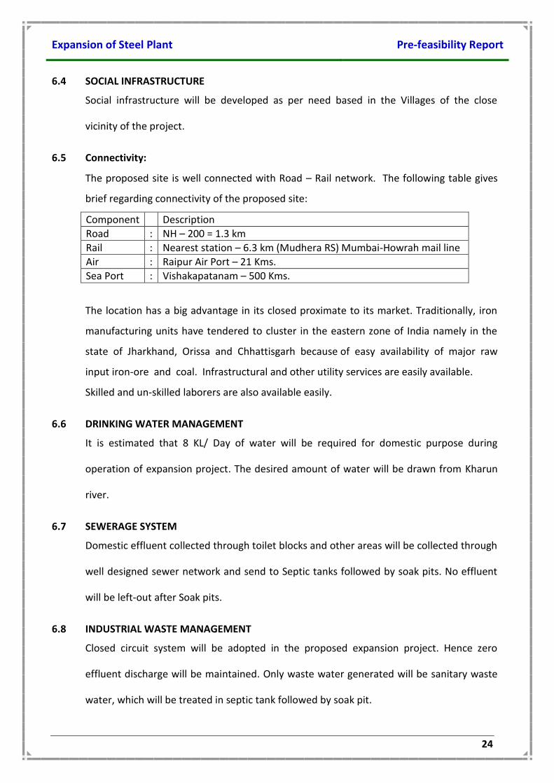
6.4 SOCIAL INFRASTRUCTURE
Social infrastructure will be developed as per need based in the Villages of the close
vicinity of the project.
6.5 Connectivity:
The proposed site is well connected with Road – Rail network. The following table gives
brief regarding connectivity of the proposed site:
Component Description
Road : NH – 200 = 1.3 km
Rail : Nearest station – 6.3 km (Mudhera RS) Mumbai-Howrah mail line
Air : Raipur Air Port – 21 Kms.
Sea Port : Vishakapatanam – 500 Kms.
The location has a big advantage in its closed proximate to its market. Traditionally, iron
manufacturing units have tendered to cluster in the eastern zone of India namely in the
state of Jharkhand, Orissa and Chhattisgarh because of easy availability of major raw
input iron-ore and coal. Infrastructural and other utility services are easily available.
Skilled and un-skilled laborers are also available easily.
6.6 DRINKING WATER MANAGEMENT
It is estimated that 8 KL/ Day of water will be required for domestic purpose during
operation of expansion project. The desired amount of water will be drawn from Kharun
river.
6.7 SEWERAGE SYSTEM
Domestic effluent collected through toilet blocks and other areas will be collected through
well designed sewer network and send to Septic tanks followed by soak pits. No effluent
will be left-out after Soak pits.
6.8 INDUSTRIAL WASTE MANAGEMENT
Closed circuit system will be adopted in the proposed expansion project. Hence zero
effluent discharge will be maintained. Only waste water generated will be sanitary waste
water, which will be treated in septic tank followed by soak pit.
Expansion of Steel Plant Pre-feasibility Report
25
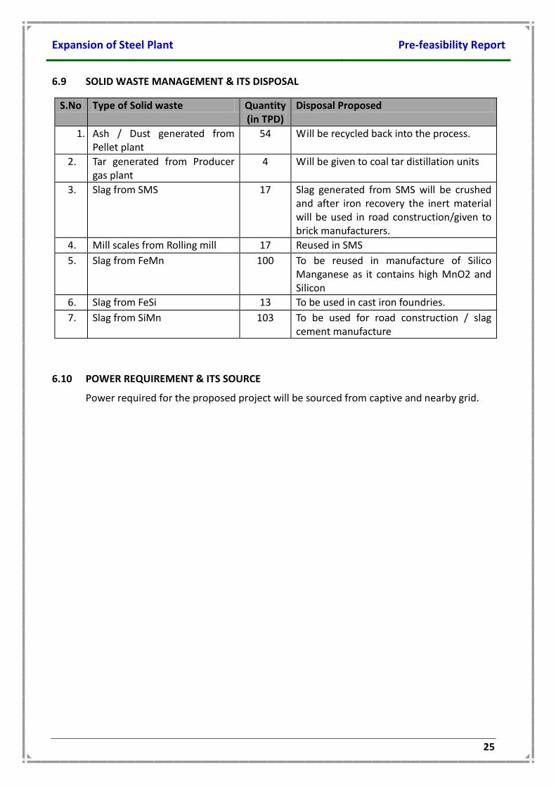
6.9 SOLID WASTE MANAGEMENT & ITS DISPOSAL
S.No Type of Solid waste Quantity (in TPD)
Disposal Proposed
1. Ash / Dust generated from Pellet plant
54 Will be recycled back into the process.
2. Tar generated from Producer gas plant
4 Will be given to coal tar distillation units
3. Slag from SMS 17 Slag generated from SMS will be crushed and after iron recovery the inert material will be used in road construction/given to brick manufacturers.
4. Mill scales from Rolling mill 17 Reused in SMS
5. Slag from FeMn 100 To be reused in manufacture of Silico Manganese as it contains high MnO2 and Silicon
6. Slag from FeSi 13 To be used in cast iron foundries.
7. Slag from SiMn 103 To be used for road construction / slag cement manufacture
6.10 POWER REQUIREMENT & ITS SOURCE
Power required for the proposed project will be sourced from captive and nearby grid.

Expansion of Steel Plant Pre-feasibility Report
26
Chapter - 7 REHABILITATION & RESETTLEMENT (R & R) PLAN
No rehabilitation and resettlement is required as there are no habitations in the in the
Project site, as proposed project site is situated in Siltara Industrial Growth Centre.
Expansion of Steel Plant Pre-feasibility Report
27
Chapter - 8 PROJECT SCHEDULE & COST ESTIMATES
8.1 PROJECT SCHEDULE
The plant will be implemented in 18 months from the date of receipt of Environmental
Clearance from the Hon’ble MoEF & NOC from CECB.
8.1 PROJECT COST
The estimated cost for the proposed project will be Rs.175 crores.
Expansion of Steel Plant Pre-feasibility Report
28
Chapter - 9 ANALYSIS OF PROPOSAL
9.1 FINANCIAL AND SOCIAL BENEFITS
With the implementation of the proposed project, the socio-economic status of the local
people will improve substantially. The land rates in the area will improve in the nearby
areas due to the proposed activity. This will help in upliftment of the social status of the
people in the area. Educational institutions will also come-up and will lead to
improvement of educational status of the people in the area. Primary health centre will
also be developed by us and the medical facilities will certainly improve due to the
proposed project.
9.2 SOCIO-ECONOMIC DEVELOPMENTAL ACTIVITIES
The management is committed to uplift the standards of living of the villagers by
undertaking following activities / responsibilities as the part of Corporate Social
Responsibility.
Health & hygiene
Drinking water
Education for poor
Village roads
Lighting
HEALTH & HYGINE
Personal and domestic hygiene,
Maintaining clean neighborhood,
Weekly health camps offering free-check up & medicines
Ambulance services
Education & drug de-addiction, aids.
DRINKING WATER
Making drinking water available at centralized locations in the village,
Expansion of Steel Plant Pre-feasibility Report
29
SUPPORTING EDUCATION
Providing books to all poor children,
Conducting annual sports festival in the village schools,
Providing amenities like fans, lavatories,
Maintain play ground etc.


![final mahendra[1]](https://img.pdfslide.us/doc/110x75/577d2e381a28ab4e1eaebc67/final-mahendra1.jpg)