Embed Size (px)
Citation preview
MAHARASHTRA STATE BOARD OF TECHNICAL EDUCATION (Autonomous)
(ISO/IEC - 27001 - 2013 Certified)
__________________________________________________________________________________________________
Page 1 of 18
SUMMER – 19 EXAMINATION Subject Name: FLUID MECHANICS AND MACHINERY Model Answer Subject C
Important Instructions to examiners: 1) The answers should be examined by key words and not as word-to-word as given in the model answer
scheme. 2) The model answer and the answer written by candidate may vary but the examiner may try to assess the
understanding level of the candidate. 3) The language errors such as grammatical, spelling errors should not be given more Importance (Not
applicable for subject English and Communication Skills. 4) While assessing figures, examiner may give credit for principal components indicated in the figure. The
figures drawn by candidate and model answer may vary. The examiner may give credit for any equivalent figure drawn.
5) Credits may be given step wise for numerical problems. In some cases, the assumed constant values may vary and there may be some difference in the candidate’s answers and model answer.
6) In case of some questions credit may be given by judgement on part of examiner of relevant answer based on candidate’s understanding.
7) For programming language papers, credit may be given to any other program based on equivalent concept.
Q.1. Attempt any FIVE of the following: 10 Marks
a) a List out the various measuring devices used for measuring fluid pressure
The Barometer, Piezometer or Pressure Tube, Manometers, The Bourdon Gauge
The Diaphragm Pressure Gauge, Micro Manometer (U-Tube with Enlarged Ends)
02
b Height of water column, h 1 = 100 m
Specific gravity of water s1 = 1.0
Specific gravity of kerosene s2 = 0.81
Specific gravity of carbon-tetra-chloride, s3 = 1.6
For the equivalent water head
Weight of the water column = Weight of the kerosene column.
So, ρg h1 s1 = r g h2 s2 = ρg h3 s3
1000x 9.81x100x1.0=1000x9.81xh2 x 0.81=1000x9.81xh3 x 1.6
h2=10/0.81
h2=12.3456m and h3=6.25m
02
22445
MAHARASHTRA STATE BOARD OF TECHNICAL EDUCATION (Autonomous)
(ISO/IEC - 27001 - 2013 Certified)
__________________________________________________________________________________________________
Page 2 of 18
c Hydraulic gradient line :
Hydraulic gradient line is basically defined as the line which will give the sum of pressure
head and datum head or potential head of a fluid flowing through a pipe with respect to
some reference line.
Total Energy Line
Total energy line is basically defined as the line which will give the sum of pressure head,
potential head and kinetic head of a fluid flowing through a pipe with respect to some
reference line.
01
01
d. For laminar flow-
i) The frictional resistance is proportional to velocity of flow.
ii) The frictional resistance is independent of
iii) The frictional resistance is proportional to the surface area in contact
iv) The frictional resistance is varies with changes in temperature
1/2 mark
each
e Draft tube:
The draft tube is a conduit which connects the runner exit to the tail race where the water
is being finally discharged from the turbine. The primary function of the draft tube is to
reduce the velocity of the discharged water to minimize the loss of kinetic energy at the
outlet.
Different types of Draft Tubes
i. Simple Elbow Draft Tube.
ii. Elbow with varying cross section.
iii. Moody Spreading Draft Tube.
iv. Conical Diffuser or Divergent Draft Tube.
01
01
f (i)Net Positive Suction Head or NPSH for pumps: It can be defined as the difference
between liquid pressure at pump suction and liquid vapor pressure, expressed in terms of
height of liquid column. Suction head is the term used to describe liquid pressure at pump
suction in terms of height of liquid column.
(ii) Cavitation: It is a phenomenon in which rapid changes of pressure in a liquid lead to
the formation of small vapor-filled cavities, in places where the pressure is relatively low.
When subjected to higher pressure, these cavities, called "bubbles" or "voids", collapse and
can generate an intense shock wave.
01 mark
01 mark
g Methods of priming.
The pumps can be primed by any of the following methods.
1.Manually 2.With vacuum pump 3.With jet pump 4.With separator
½ each
MAHARASHTRA STATE BOARD OF TECHNICAL EDUCATION (Autonomous)
(ISO/IEC - 27001 - 2013 Certified)
__________________________________________________________________________________________________
Page 3 of 18
2 Attempt any THREE of the following: 12
a There are three physical properties of fluids that are particularly important: density,
viscosity, and surface tension. Density. Density depends on the mass of an individual
molecule and the number of such molecules that occupy a unit of volume For liquids,
viscosity also depends strongly on the temperature; Water at 20°C has a surface tension of
72.8 dynes/cm compared 465 for mercury.
Water Mercury
I. Density of water=998 kg/m3 at 20
0c Density of mercuryr=13550 kg/m
3 at 20
0c
II. kinematic viscosity= 0.657x 10⁶
kinematic viscosity= 0.109x 10⁶
III. surface tension =71.78 N/m surface tension = 4.6 x 10 -1
N/m
1 each
b Area = bxd = 0.6x1.2 =0.72 m2
X = 0.7+ 0.6 sin450 =0.7+0.6x0.707=1.1243m
Force = wAx = 9810x 0.72x1.1243=7940.90N
Centre of pressure h = Ig sin245/A x + x
Ig = bd3/12 = 0.6 x 1.2
3/12 = 0.0864m
4
h= 0.0864x0.5/0.72x1.1243+1.1243=1.243m
01 mark
01 mark
01 mark
01 mark
c An orifice plate: It is a thin plate with a hole in it, which is usually placed in a pipe. When
a fluid (whether liquid or gaseous) passes through the orifice, its pressure builds up slightly
upstream of the orifice but as the fluid is forced to converge to pass through the hole, the
velocity increases and the fluid pressure decreases. A little downstream of the orifice the
flow reaches its point of maximum convergence, the vena contracta where the velocity
reaches its maximum and the pressure reaches its minimum. Beyond that, the flow
expands, the velocity falls and the pressure increases.
04 marks
d
01 mark
Sketch
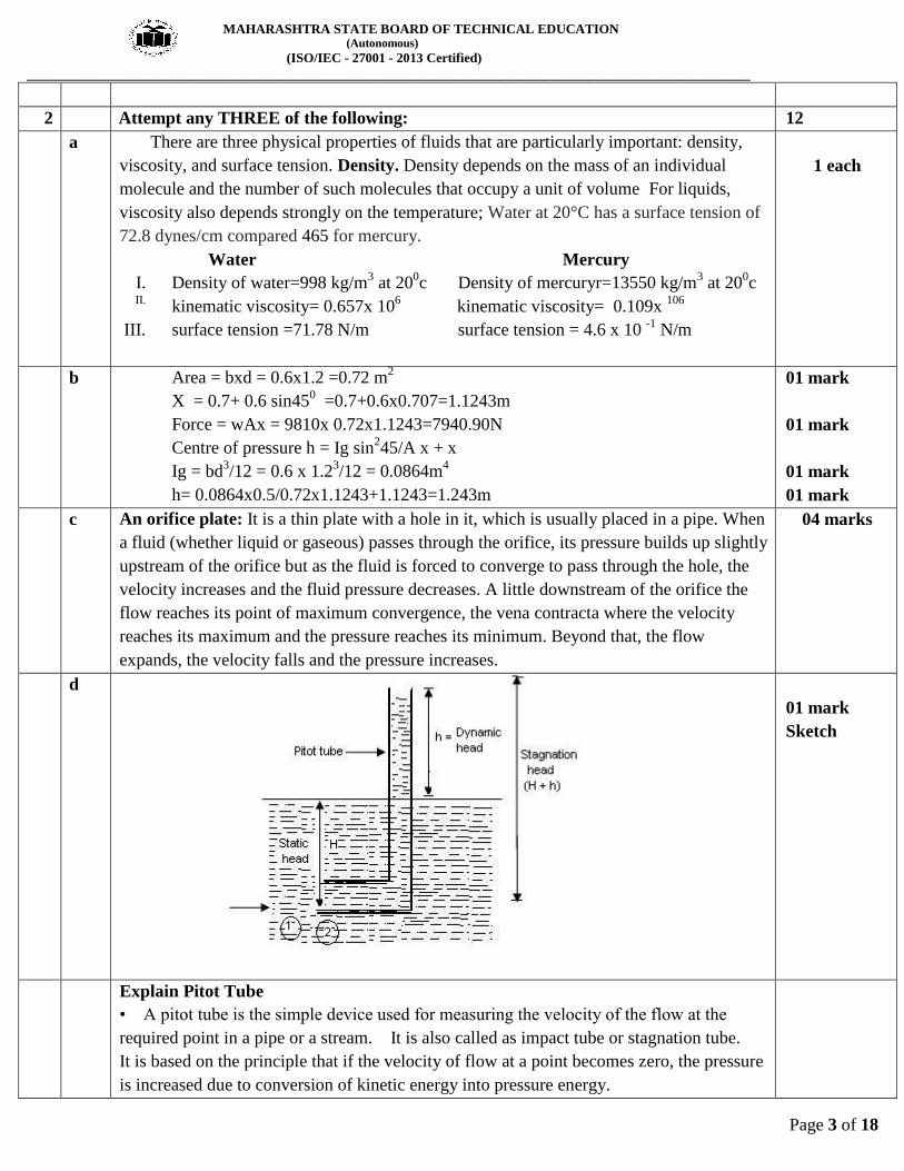
Explain Pitot Tube
• A pitot tube is the simple device used for measuring the velocity of the flow at the
required point in a pipe or a stream. It is also called as impact tube or stagnation tube.
It is based on the principle that if the velocity of flow at a point becomes zero, the pressure
is increased due to conversion of kinetic energy into pressure energy.
MAHARASHTRA STATE BOARD OF TECHNICAL EDUCATION (Autonomous)
(ISO/IEC - 27001 - 2013 Certified)
__________________________________________________________________________________________________
Page 4 of 18
• In its simple form, a pitot tube consists of a transparent glass tube bent through 900 and
with ends unsealed. Diameter of tube is larger enough to neglect capillary effects. One
leg called as the body is inserted into the flow at upstream and aligned with the direction of
flow whereas the other leg, called as stem, is vertical and open to atmosphere. The liquid is
raise in the tube due to changes in energy. The velocity is determined by measuring the
rise in the tube.
Consider a section 1 and 2 at a same level just in front of inlet of the tube
Apply Bernoulli’s equation
P1/ γ + V12 / 2g + Z1 = P2 / γ + V2
2 / 2g + Z2
Z1 = Z2 as they are at same level
V2 = 0 because flow of particle is comes to rest at point 2.
h = rise in tube
H = head of pressure at
h + H = stagnation head
Substitute above value in Bernoulli’s
H + V12 / 2g = h + H h = V1
2 / 2g
V1 = √2gh
Actual velocity V = Cv V theoretical
V = Cv √2gh
Where Cv = Coefficient of velocity
03 marks
Explain
Q. No.
Sub Q. N.
Answer Marking Scheme
3
3
a
b
Interpret the type of flow (Laminar / Turbulent)
i. Laminar Flow
ii. Turbulent Flow
iii. Laminar Flow
iv. Turbulent Flow
Water hammer phenomenon: commonly occurs when a valve closes suddenly at an end of
a pipeline system, and a pressure wave propagates in the pipe.
To reduce / avoid water hammer effect following things are used.
1. Provide surge tank before the valve on main pipe line.
2. Provide bypass pipe near the valve.
3. Provide Air traps or stand pipes (open at the top) to absorb the potentially damaging
forces caused by the moving water.
4. Use high strength pipes.
5. Close the valve slowly.
01 Mark each
02 Marks for Cause
02 Marks for any 2 effects
MAHARASHTRA STATE BOARD OF TECHNICAL EDUCATION (Autonomous)
(ISO/IEC - 27001 - 2013 Certified)
__________________________________________________________________________________________________
Page 5 of 18
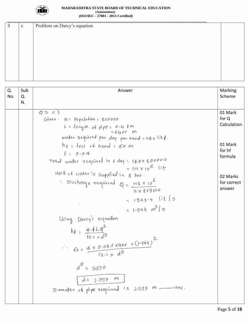
3
c Problem on Darcy’s equation
Q. No.
Sub Q. N.
Answer Marking Scheme
01 Mark for Q Calculation
01 Mark for hf formula
02 Marks for correct answer
MAHARASHTRA STATE BOARD OF TECHNICAL EDUCATION (Autonomous)
(ISO/IEC - 27001 - 2013 Certified)
__________________________________________________________________________________________________
Page 6 of 18
Q. No.
Sub Q. N.
Answer Marking Scheme
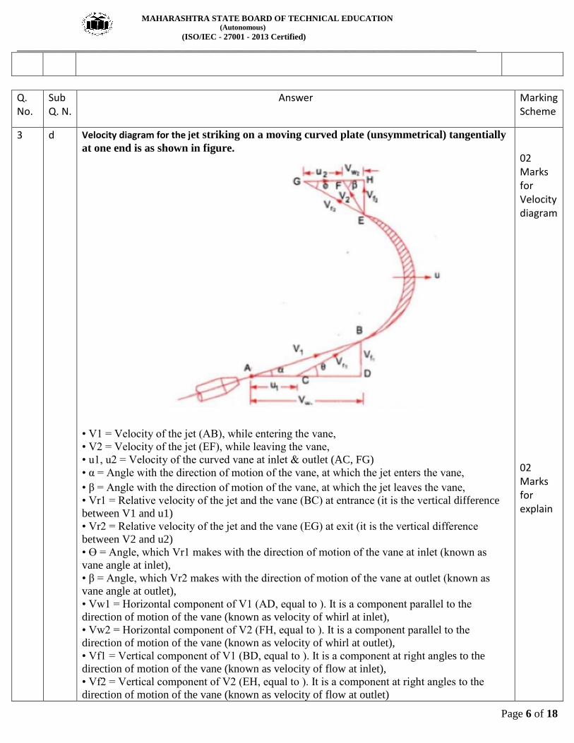
3
d Velocity diagram for the jet striking on a moving curved plate (unsymmetrical) tangentially
at one end is as shown in figure.
• V1 = Velocity of the jet (AB), while entering the vane,
• V2 = Velocity of the jet (EF), while leaving the vane,
• u1, u2 = Velocity of the curved vane at inlet & outlet (AC, FG)
• α = Angle with the direction of motion of the vane, at which the jet enters the vane,
• β = Angle with the direction of motion of the vane, at which the jet leaves the vane,
• Vr1 = Relative velocity of the jet and the vane (BC) at entrance (it is the vertical difference
between V1 and u1)
• Vr2 = Relative velocity of the jet and the vane (EG) at exit (it is the vertical difference
between V2 and u2)
• Ɵ = Angle, which Vr1 makes with the direction of motion of the vane at inlet (known as
vane angle at inlet),
• β = Angle, which Vr2 makes with the direction of motion of the vane at outlet (known as
vane angle at outlet),
• Vw1 = Horizontal component of V1 (AD, equal to ). It is a component parallel to the
direction of motion of the vane (known as velocity of whirl at inlet),
• Vw2 = Horizontal component of V2 (FH, equal to ). It is a component parallel to the
direction of motion of the vane (known as velocity of whirl at outlet),
• Vf1 = Vertical component of V1 (BD, equal to ). It is a component at right angles to the
direction of motion of the vane (known as velocity of flow at inlet),
• Vf2 = Vertical component of V2 (EH, equal to ). It is a component at right angles to the
direction of motion of the vane (known as velocity of flow at outlet)
02 Marks for Velocity diagram
02 Marks for explain

MAHARASHTRA STATE BOARD OF TECHNICAL EDUCATION (Autonomous)
(ISO/IEC - 27001 - 2013 Certified)
__________________________________________________________________________________________________
Page 7 of 18
Q. No.
Sub Q. N.
Answer Marking Scheme
3
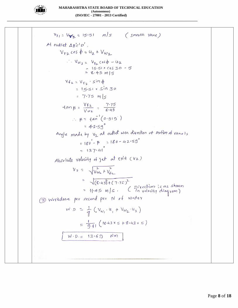
e
01 Mark for correct value of angle
02 Mark for correct value of v2
01 Marks for correct value of Workdone
MAHARASHTRA STATE BOARD OF TECHNICAL EDUCATION (Autonomous)
(ISO/IEC - 27001 - 2013 Certified)
__________________________________________________________________________________________________
Page 8 of 18
MAHARASHTRA STATE BOARD OF TECHNICAL EDUCATION (Autonomous)
(ISO/IEC - 27001 - 2013 Certified)
__________________________________________________________________________________________________
Page 9 of 18
Q. No.
Sub Q. N.
Answer Marking Scheme
4
4
a
b
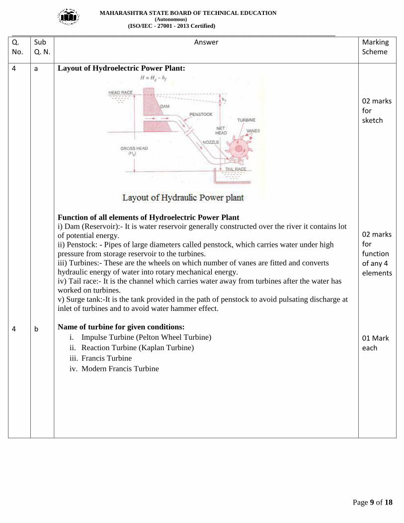
Layout of Hydroelectric Power Plant:
Function of all elements of Hydroelectric Power Plant
i) Dam (Reservoir):- It is water reservoir generally constructed over the river it contains lot
of potential energy.
ii) Penstock: - Pipes of large diameters called penstock, which carries water under high
pressure from storage reservoir to the turbines.
iii) Turbines:- These are the wheels on which number of vanes are fitted and converts
hydraulic energy of water into rotary mechanical energy.
iv) Tail race:- It is the channel which carries water away from turbines after the water has
worked on turbines.
v) Surge tank:-It is the tank provided in the path of penstock to avoid pulsating discharge at
inlet of turbines and to avoid water hammer effect.
Name of turbine for given conditions:
i. Impulse Turbine (Pelton Wheel Turbine)
ii. Reaction Turbine (Kaplan Turbine)
iii. Francis Turbine
iv. Modern Francis Turbine
02 marks for sketch
02 marks for function of any 4 elements
01 Mark each
MAHARASHTRA STATE BOARD OF TECHNICAL EDUCATION (Autonomous)
(ISO/IEC - 27001 - 2013 Certified)
__________________________________________________________________________________________________
Page 10 of 18
Q. No.
Sub Q. N.
Answer Marking Scheme
4
4
c
d
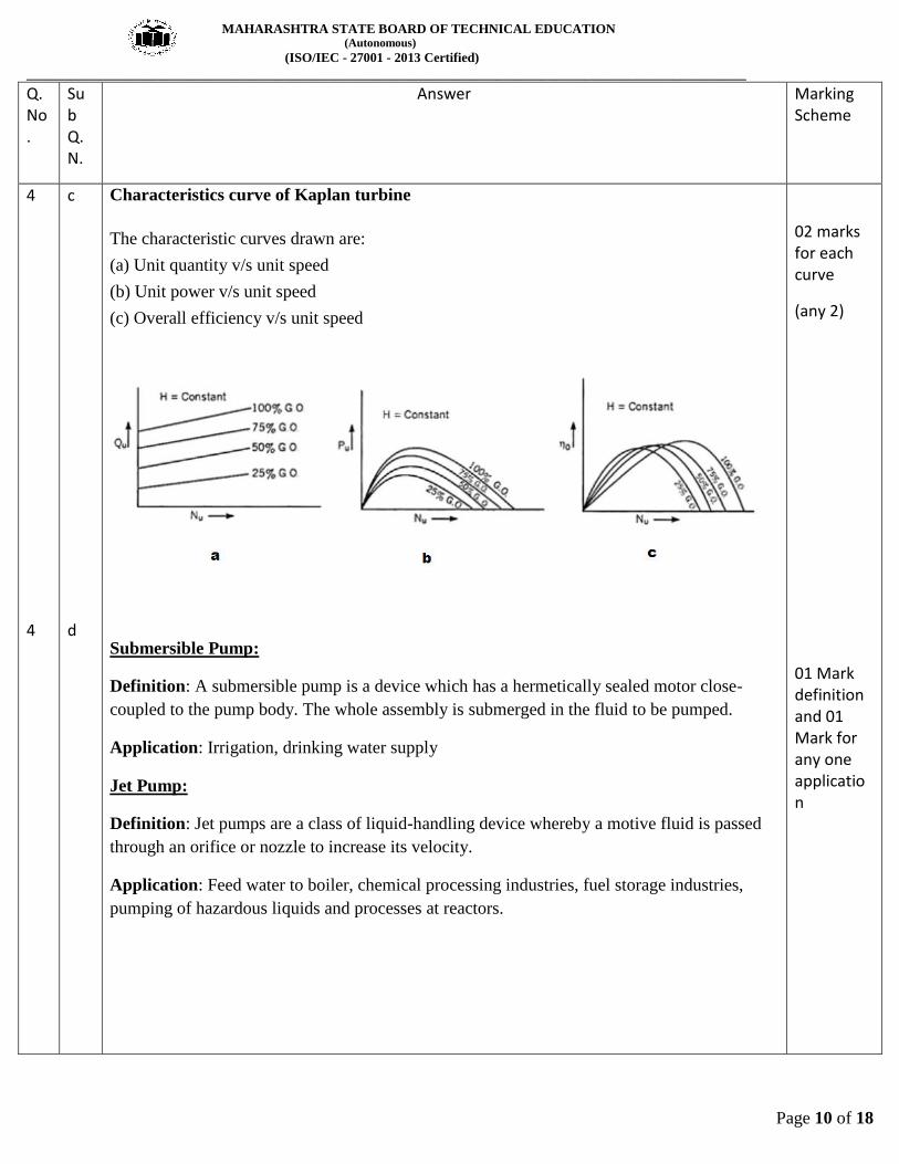
Characteristics curve of Kaplan turbine
The characteristic curves drawn are:
(a) Unit quantity v/s unit speed
(b) Unit power v/s unit speed
(c) Overall efficiency v/s unit speed
Submersible Pump:
Definition: A submersible pump is a device which has a hermetically sealed motor close-
coupled to the pump body. The whole assembly is submerged in the fluid to be pumped.
Application: Irrigation, drinking water supply
Jet Pump:
Definition: Jet pumps are a class of liquid-handling device whereby a motive fluid is passed
through an orifice or nozzle to increase its velocity.
Application: Feed water to boiler, chemical processing industries, fuel storage industries,
pumping of hazardous liquids and processes at reactors.
02 marks for each curve
(any 2)
01 Mark definition and 01 Mark for any one application
MAHARASHTRA STATE BOARD OF TECHNICAL EDUCATION (Autonomous)
(ISO/IEC - 27001 - 2013 Certified)
__________________________________________________________________________________________________
Page 11 of 18
Q. No.
Sub Q. N.
Answer Marking Scheme
4
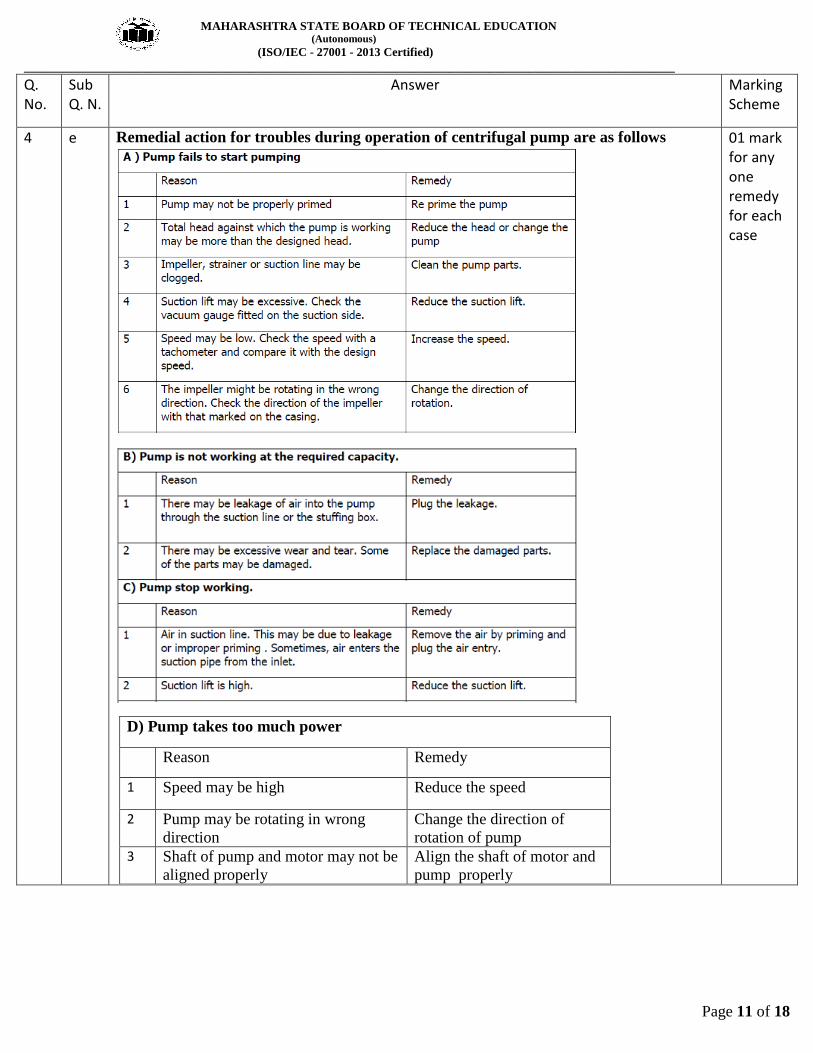
e Remedial action for troubles during operation of centrifugal pump are as follows
D) Pump takes too much power
Reason Remedy
1 Speed may be high Reduce the speed
2 Pump may be rotating in wrong
direction
Change the direction of
rotation of pump
3 Shaft of pump and motor may not be
aligned properly
Align the shaft of motor and
pump properly
01 mark for any one remedy for each case
MAHARASHTRA STATE BOARD OF TECHNICAL EDUCATION (Autonomous)
(ISO/IEC - 27001 - 2013 Certified)
__________________________________________________________________________________________________
Page 12 of 18
Q.
No.
Sub
Q. N.
Answer Marking
Scheme
Q. 5 Attempt any TWO of the following 12 Marks
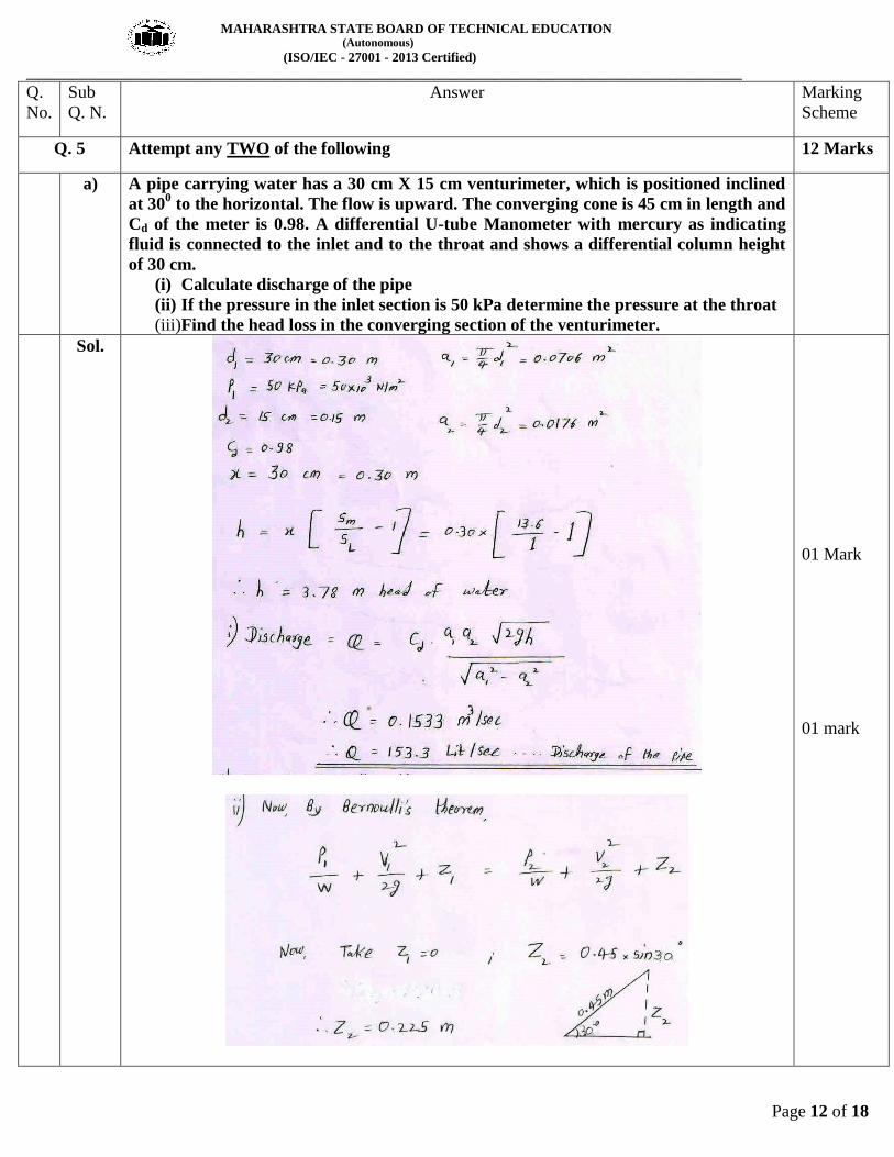
a) A pipe carrying water has a 30 cm X 15 cm venturimeter, which is positioned inclined
at 300 to the horizontal. The flow is upward. The converging cone is 45 cm in length and
Cd of the meter is 0.98. A differential U-tube Manometer with mercury as indicating
fluid is connected to the inlet and to the throat and shows a differential column height
of 30 cm.
(i) Calculate discharge of the pipe
(ii) If the pressure in the inlet section is 50 kPa determine the pressure at the throat
(iii)Find the head loss in the converging section of the venturimeter.
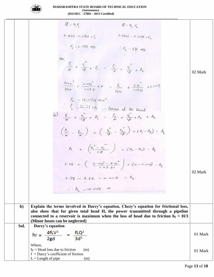
Sol.
01 Mark
01 mark
MAHARASHTRA STATE BOARD OF TECHNICAL EDUCATION (Autonomous)
(ISO/IEC - 27001 - 2013 Certified)
__________________________________________________________________________________________________
Page 13 of 18
02 Mark
02 Mark
b) Explain the terms involved in Darcy’s equation, Chezy’s equation for frictional loss,
also show that for given total head H, the power transmitted through a pipeline
connected to a reservoir is maximum when the loss of head due to friction hf = H/3
(Minor losses can be neglected)
Sol. Darcy’s equation
Where,
hf = Head loss due to friction (m)
f = Darcy’s coefficient of friction
L = Length of pipe (m)
01 Mark
01 Mark
MAHARASHTRA STATE BOARD OF TECHNICAL EDUCATION (Autonomous)
(ISO/IEC - 27001 - 2013 Certified)
__________________________________________________________________________________________________
Page 14 of 18
V = Velocity of flowing fluid (m/s)
Q = Discharge through pipe (m3/s)
d = Diameter of pipe (m)
g = Acceleration due to gravity (9.81 m/s2)
Chezy’s equation
Where,
V = velocity of water in pipe
m = hydraulic mean depth =A/P = d/4
i = loss of head per unit length = hf/L
C =Chezy’s constant
Power Transmitted Through a Pipe
Power = W x Q x ( H - hf )
For Maximum Power Transmission
Power = W x Q x ( H – H/3)
Where,
W = Specific Weight of fluid (N/m3)
Q = Volume flow rate (m3/s)
H = Head of fluid available at inlet of pipe (m) hf = Head loss due to friction (m)
01 Mark
01 Mark
01 Mark
01 Mark
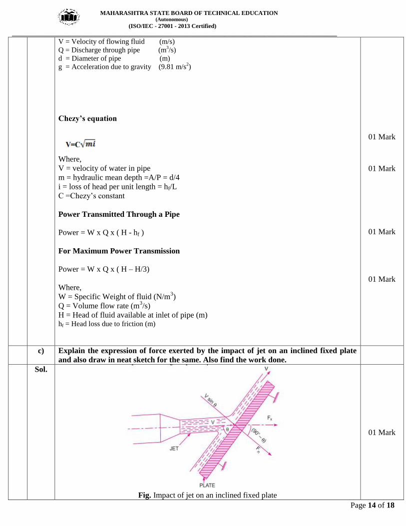
c) Explain the expression of force exerted by the impact of jet on an inclined fixed plate
and also draw in neat sketch for the same. Also find the work done.
Sol.
Fig. Impact of jet on an inclined fixed plate
01 Mark
MAHARASHTRA STATE BOARD OF TECHNICAL EDUCATION (Autonomous)
(ISO/IEC - 27001 - 2013 Certified)
__________________________________________________________________________________________________
Page 15 of 18
Let,
d = diameter of jet
a = Area of jet = (π/4) d2 V = Velocity of jet before striking the plate
Vsinθ = component of velocity normal to plate
m = mass of water striking the plate per sec in Kg.
m= ρ a V
Fn = Normal force on the plate.
Fn = mass of water X (velocity before impact in the direction normal to plate - Velocity
after impact in the direction normal to plate )
Fn = ρ a V (Vsinθ - 0)
= ρ a V2sinθ
Fx = Force in the direction of jet = Fn sinθ = ρ a V2sin
2θ
Fy = Force in the direction normal to the jet = Fn cosθ = ρ a V2sinθ x cosθ
Work done = 0 …..since plate is stationary
01 Mark
01 Mark
01 Mark
01 Mark
01 Mark
Q.6 Attempt any TWO of the following 12 Marks
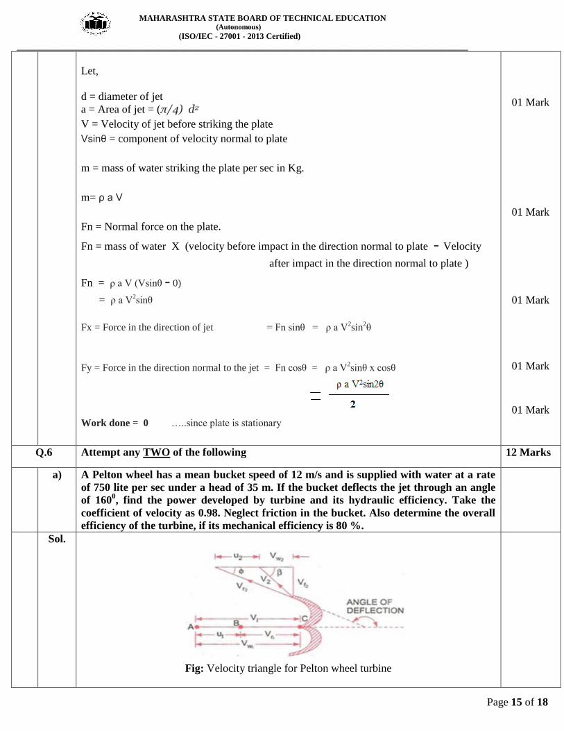
a) A Pelton wheel has a mean bucket speed of 12 m/s and is supplied with water at a rate
of 750 lite per sec under a head of 35 m. If the bucket deflects the jet through an angle
of 1600, find the power developed by turbine and its hydraulic efficiency. Take the
coefficient of velocity as 0.98. Neglect friction in the bucket. Also determine the overall
efficiency of the turbine, if its mechanical efficiency is 80 %.
Sol.
Fig: Velocity triangle for Pelton wheel turbine
MAHARASHTRA STATE BOARD OF TECHNICAL EDUCATION (Autonomous)
(ISO/IEC - 27001 - 2013 Certified)
__________________________________________________________________________________________________
Page 16 of 18
Data: U1 = 12 m/s
Q = 750 lit/sec = 0.750 m3/s
H = 35 m
Ø = 1800 – 160
0 = 20
0
Cv = 0.98
Ƞmech = 80 % = 0.80
Power = ?
Ƞhyd = ?
Ƞoverall = ?
= 0.98 x (2 x 9.81 x 35)1/2
= 25.68 m/s
From Inlet Velocity triangle, Vw1 = V1 = 25.68 m/s
Vr1 = V1 – U1 = 25.68 – 12 = 13.68 m/s
But, Vr2 = Vr1 = 13.68 m/s
From Outlet Velocity triangle,
Vw2 = cos Ø Vr2 - U = (cos 200 x 13.68) - 12
Vw2 = 0.8558 m/s
Power = ρQ (Vw1 + Vw2) U
Power = 238.82 X 10³ Watt
= 92.74 %
02 Marks
02 Marks
02 Marks
MAHARASHTRA STATE BOARD OF TECHNICAL EDUCATION (Autonomous)
(ISO/IEC - 27001 - 2013 Certified)
__________________________________________________________________________________________________
Page 17 of 18
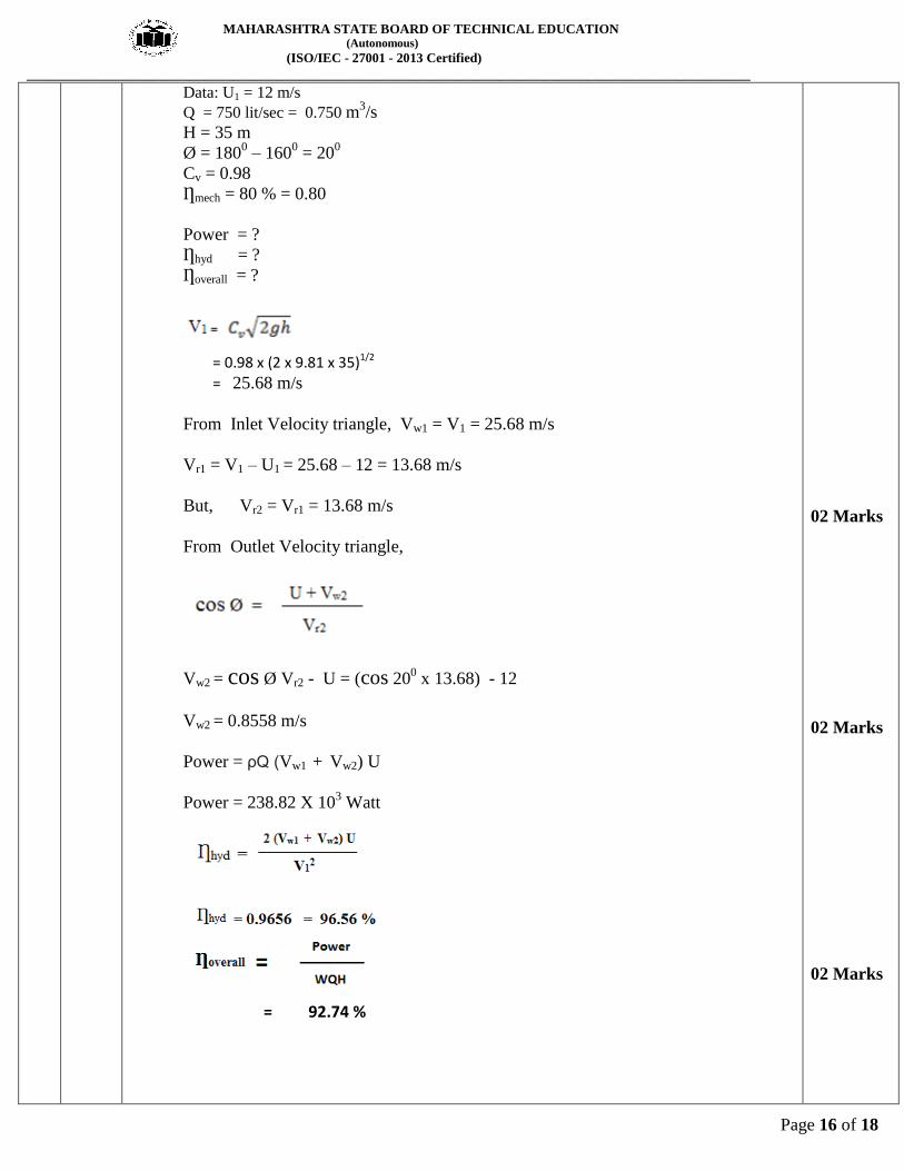
b) Draw indicator diagrams of a reciprocating pump showing the effect of acceleration
and friction head on suction and delivery pipes connected with air vessels and without
air vessels.
Sol.
Fig. Effect of acceleration and friction in
indicator diagram with air vessels
Fig. Effect of acceleration and friction in
indicator diagram without air vessels
03 Marks
for each
diagram
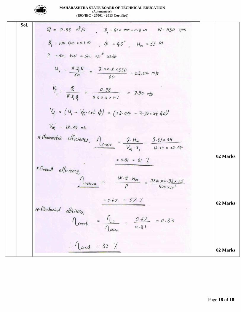
c) A centrifugal pump has following characteristics: outer diameter of impeller = 800 mm;
width of impeller vanes at outlet = 100 mm; angle of impeller vanes at outlet = 400. The
impeller runes at 550 rpm and delivers 0.98 cubic meters of water per sec under an
effective head of 35 m. a 500 KW motors is used to drive the pump. Determine the
manometric, mechanical and overall efficiencies of the pump. Assume water enters the
impeller vanes radially at inlet.
MAHARASHTRA STATE BOARD OF TECHNICAL EDUCATION (Autonomous)
(ISO/IEC - 27001 - 2013 Certified)
__________________________________________________________________________________________________
Page 18 of 18
Sol.
02 Marks
02 Marks
02 Marks