Embed Size (px)
Citation preview

MAHARASHTRA STATE BOARD OF TECHNICAL EDUCATION
(Autonomous)
(ISO/IEC-27001-2013 Certified) __________________________________________________________________________________________
Summer– 2018 Examinations
Model Answer Subject Code: 17508 (SAP)
Page No: 1 of 17
Important Instructions to examiners:
1) The answers should be examined by key words and not as word-to-word as given in the model
answer scheme.
2) The model answer and the answer written by candidate may vary but the examiner should assess the
understanding level of the candidate.
3) The language errors such as grammatical, spelling errors should not be given importance.
(Not applicable for subject English and Communication Skills).
4) While assessing figures, examiner may give credit for principal components indicated in the figure.
The figures drawn by candidate and model answer may vary. The examiner should give credit for
any equivalent figure/figures drawn.
5) Credits to be given step wise for numerical problems. In some cases, the assumed constant values
may vary and there may be some difference in the candidate’s answers and model answer (as long
as the assumptions are not incorrect).
6) In case of some questions credit may be given by judgment on part of examiner of relevant answer
based on candidate’s understanding.
7) For programming language papers, credit may be given to any other program based on equivalent
concept

MAHARASHTRA STATE BOARD OF TECHNICAL EDUCATION
(Autonomous)
(ISO/IEC-27001-2013 Certified) __________________________________________________________________________________________
Summer– 2018 Examinations
Model Answer Subject Code: 17508 (SAP)
Page No: 2 of 17
1 a) Attempt any THREE of the following: 12
1 a) (i) State any four differences between symmetrical and asymmetrical fault. (any
four points)
Ans:
Difference between symmetrical and asymmetrical fault:
Sr.
No.
Symmetrical fault Asymmetrical fault
1 The fault on the power system
which gives rise to symmetrical
fault currents in the system is
called symmetrical fault.
The fault on the power system
which gives rise to unsymmetrical
fault currents in the system is
called unsymmetrical fault.
2 These faults occur very rarely in
practice.
These faults occur for majority of
times in practice.
3 It is more severe type of fault in
nature.
It is comparatively somewhat less
severe type of fault.
4 The nature of this type of fault
is balanced.
The nature of this type of fault is
unbalanced.
5 Because of balance nature of
fault, only one phase need to be
considered in calculations.
Because of unbalance nature of
fault, all three phases need to be
considered in calculations.
6 Symmetrical fault imposes
more heavy duty on circuit
breakers.
Unsymmetrical fault imposes
somewhat less duty on circuit
breakers.
7 Symmetrical fault calculations
and analysis is comparatively
simple & easy.
Unsymmetrical fault calculations
and analysis is complicated &
tedious.
8 Symmetrical faults involve all
the three phases.
Unsymmetrical faults involve one
or two phases.
9 Examples: (a) L-L-L Fault
(b) L-L-L-G Fault.
Examples: (a) L-G Fault
(b) L-L-G Fault
(c) L-L Fault etc.
Each point
1 Mark
(any four
points)
= 4 Marks
1 a) (ii) Draw neat circuit diagram of
1) Bus bar reactor
2) Feeder reactor
3) Generator reactor
Ans:
1) Bus bar reactor
Ring system Tie - Bar system
2 Marks

MAHARASHTRA STATE BOARD OF TECHNICAL EDUCATION
(Autonomous)
(ISO/IEC-27001-2013 Certified) __________________________________________________________________________________________
Summer– 2018 Examinations
Model Answer Subject Code: 17508 (SAP)
Page No: 3 of 17
2) Feeder reactor
3) Generator reactor
1 Mark
1 Mark
1 a) (iii) Draw neat circuit diagram of Balanced beam type relay.
Ans:
Balanced Beam Type Relay:
Labeled diagram 4 Marks
Partially Labeled diagram 3 Marks
Un-Labeled
diagram 2 Marks
1 a) (iv) State any four properties of good protective system.
Ans:
Properties of good protective system: i) Selectivity: It is the ability of protective system to select correctly that part of
system in trouble and disconnect the faulty part without disturbing the rest of the
system.
ii) Speed: The relay system should disconnect the faulty section as fast as possible
to prevent the electrical apparatus from damage and for system stability.
iii) Sensitivity: It is the ability of the relay system to operate with low value of
actuating quantity. iv) Reliability: It is the ability of the relay system to operate under
predetermined conditions. v) Simplicity: The relay system should be simple so that it can be easily
maintained. vi) Economy: The most important factor in the choice of particular protection
Each point
1 Mark
(any four
points)
= 4 Marks

MAHARASHTRA STATE BOARD OF TECHNICAL EDUCATION
(Autonomous)
(ISO/IEC-27001-2013 Certified) __________________________________________________________________________________________
Summer– 2018 Examinations
Model Answer Subject Code: 17508 (SAP)
Page No: 4 of 17
scheme is the economic aspect. The protective gear should not cost more than 5% of the total cost of equipment to be protected.
1 b) Attempt any ONE of the following: 6
1 b) (i) Draw circuit diagram for men merz price protection scheme for Delta-Delta (D-
D) connected 3 phase power transformer.
Ans:
Merz price protection scheme for Delta-Delta(D-D) connected 3 phase
Power Transformer:
Labeled diagram 6 Marks
Partially Labeled diagram 5 Marks
Un-Labeled
diagram 4 Marks
1 b) (ii) Two 11kV, 3 phase, 5000kVA generators having reactances of 20% operate in
parallel. The generator supply power to transmission line through 3000kVA
transformer of ratio 22kV/33kV having leakage reactance of 6%. Calculate
Fault kVA on H.T. side of transformer.
Ans:
Assume base KVA = 5000 KVA
% Reactance related to base KVA
% X = (Base KVA / Rated KVA) x % Reactance on Rated KVA
XG1 = (5000/5000) x 20%
= 20 %
Similarly,
XG2 = 20 %
XT = (5000/3000) x 6
= 10 %
For Fault F (HT side)
Total reactance is %X = (XG1 || XG2) + XT
1 Mark for
reactance
diagram
2 Marks for
reactance
calculation
MAHARASHTRA STATE BOARD OF TECHNICAL EDUCATION
(Autonomous)
(ISO/IEC-27001-2013 Certified) __________________________________________________________________________________________
Summer– 2018 Examinations
Model Answer Subject Code: 17508 (SAP)
Page No: 5 of 17
= (20||20)+10 = 10 + 10 % X = 20 %
Rated current at base KVA
I = (5000 x 1000) / (√3 x 33 x 1000)
I = 87.477 Amp.
ISC = I x (100 / % X)
= 87.477 x (100 / 20)
ISC = 437.385 amp
S.C. KVA = Base KVA x (100/ % X)
= 5000 x (100 /20)
= 25000 KVA
S.C. MVA = 25 MVA
2 Marks for
stepwise
solution of ISC
1 Mark for
SC MVA
2 Attempt any FOUR of the following: 16
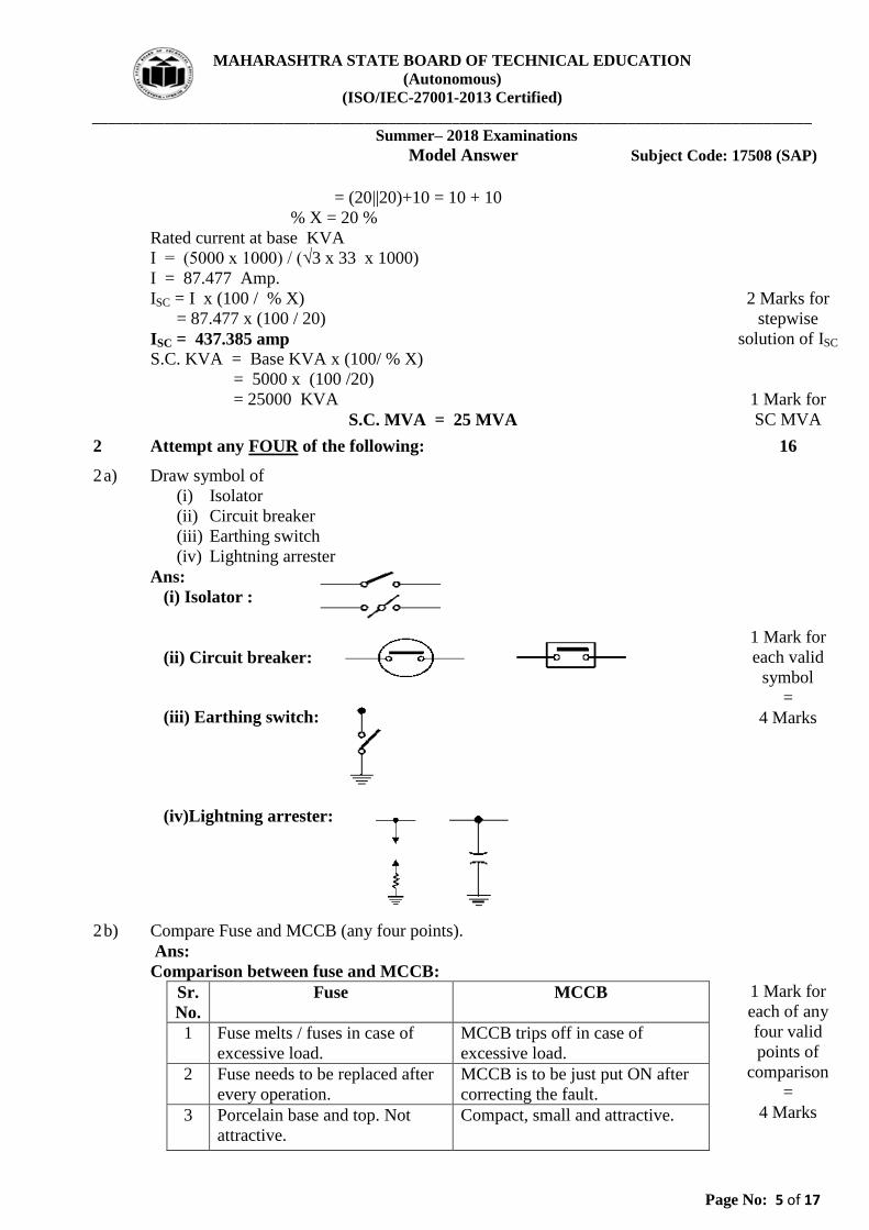
2 a) Draw symbol of
(i) Isolator
(ii) Circuit breaker
(iii) Earthing switch
(iv) Lightning arrester
Ans:
(i) Isolator :
(ii) Circuit breaker:
(iii) Earthing switch:
(iv)Lightning arrester:
1 Mark for
each valid
symbol
=
4 Marks
2 b) Compare Fuse and MCCB (any four points).
Ans:
Comparison between fuse and MCCB:
Sr.
No.
Fuse MCCB
1 Fuse melts / fuses in case of
excessive load.
MCCB trips off in case of
excessive load.
2 Fuse needs to be replaced after
every operation.
MCCB is to be just put ON after
correcting the fault.
3 Porcelain base and top. Not
attractive.
Compact, small and attractive.
1 Mark for
each of any
four valid
points of
comparison
=
4 Marks

MAHARASHTRA STATE BOARD OF TECHNICAL EDUCATION
(Autonomous)
(ISO/IEC-27001-2013 Certified) __________________________________________________________________________________________
Summer– 2018 Examinations
Model Answer Subject Code: 17508 (SAP)
Page No: 6 of 17
4 Works on melting / fusing due
to high temperature.
Works on bi–metal expansion or
induced magnetism.
5 Relatively economical than
MCCB.
Relatively costlier than fuse.
6 Simple in construction. Complicated in construction.
7 Operating time is very small.
(0.002 sec or so)
Operating time is comparatively
large. (0.1 to 0.2 sec)
8 Risk in putting on the fuse
element.(Unsafe)
No risk in putting “ON” the
MCCB. (Safe).
9 Generally protects the load
against short-circuit.
Generally protects the load
against different types of faults.
2 c) Define the following terms:
(i) Arc voltage
(ii) Recovery voltage
(iii)RRRV
(iv) Restriking voltage
Ans:
i) Arc Voltage: The voltage existing between the circuit breaker contacts
during arcing is called as the arc voltage.
ii) Recovery voltage: The normal power frequency voltage that appears
across the contacts after the arc is finally extinguished and the transients
have fully disappeared is the recovery voltage.
iii) RRRV: The RRRV (rate of rise of the restriking voltage) is defined as the
slope of the steepest tangent to the restriking voltage curve. It is expressed
in volts per micro-second.
iv) Restriking voltage: The transient voltage that appears across the contacts
of the circuit breaker at the instant of the arc getting extinguished is called
as the restriking voltage.
1 Mark for
each definition
=
4 Marks
2 d) Explain with neat diagram rod gap type lightning arrestor.
Ans:
Rod Gap Type Lightning Arrestor:
It consists of two 1.5cm rods which are bent at right angles with a gap in
between as shown in figure. One rod is connected to line and other rod is
connected to earth.
Under normal operating conditions the gap remains non-conducting. On the
occurrence of high voltage surge on the line, the gap sparks over and the surge
current is conducted to earth safely.
2 Marks for
explanation
2 Marks for
diagram

MAHARASHTRA STATE BOARD OF TECHNICAL EDUCATION
(Autonomous)
(ISO/IEC-27001-2013 Certified) __________________________________________________________________________________________
Summer– 2018 Examinations
Model Answer Subject Code: 17508 (SAP)
Page No: 7 of 17
2 e) Compare Resistance earthing and Reactance earthing. (any four points)
Ans:
Comparison between Resistance earthing and Reactance earthing:
Sr. No. Resistance earthing Reactance earthing
1.
2. Neutral is connected to ground
through resistance
Neutral is connected to
ground through inductance
3. Economical Expensive
4. Minimizes arcing earth faults Made arcing earth faults self-
extinguishing
5. Suitable for high capacity
lightning arrestor
Suitable for low capacity
lightning arrestor
6. Suitable for moderate capacity
circuit breakers
Suitable for low capacity
circuit breakers
7. Used upto 33kV system Used above 33kV system.
1 Mark for
each of any
four valid
points of
comparison
=
4 Marks
2 f) Draw neat circuit diagram of solenoid type relay.
Ans:
Solenoid Type Relay:
Labeled diagram 4 Marks
Partially Labeled diagram 3 Marks
Un-Labeled
diagram 2 Marks
3 Attempt any FOUR of the following: 16
3 a) Draw and explain neat circuit diagram of MCB.
Ans:
Miniature Circuit Breaker (MCB):
MCB is used to provide protection against overloads and short circuits. It
consists of inbuilt thermal bimetal element and electromagnetic coil. The
bimetal heats up and bends in response to overcurrent conditions to unlatch a
spring operated mechanism to open the contacts. Under short circuit condition,
the heavy current passing through magnetic coil produces sufficient pull to
separate the contacts thus provides protction against short circuit.
2 Marks for
explanation

MAHARASHTRA STATE BOARD OF TECHNICAL EDUCATION
(Autonomous)
(ISO/IEC-27001-2013 Certified) __________________________________________________________________________________________
Summer– 2018 Examinations
Model Answer Subject Code: 17508 (SAP)
Page No: 8 of 17
2 Marks for
diagram
3 b) Draw and explain neat circuit diagram of Vacuum Circuit Breaker.
Ans:
Vacuum Circuit Breaker:
Explanation:
During the operation of the breaker, the moving contact separates from the fixed
contact resulting in arcing between them. The production of arc is due to the
ionization of metal ions and depends very much upon the materials of contacts.
The arc is quickly extinguished because the metallic vapours, electrons and ions
produced during arc are diffused in a short time and seized by the surface of
moving and fixed members and shields. The arc gets extinguished quickly as
vacuum has good recovery of dielectric strength. The arc extinction occurs at a
small vacuum gap of about 0.6 to 0.7cm.
2 Marks for
diagram
2 Marks for
explanation
3 c) Write function of Buchholz relay and state application of it for transformer
protection
Ans:
Function of Buchholz relay: It is used for the protection of transformers from the faults occurring inside the
transformer. Short circuit faults such as inter-turn faults, incipient winding
faults, core faults etc. may occur due to the impulse breakdown of the
insulation. To protect transformer against these faults, Buchholz relay is used.
Appliction of Buchholz relay for transformer protection:
It is universal practice to use Buchholz relay on all oil immersed transformers
having rating in exess of 750 kVA at generation power plant, receving sub-station,
distribution sub-station, power transformers in industry etc.
2 Marks
2 Marks
.

MAHARASHTRA STATE BOARD OF TECHNICAL EDUCATION
(Autonomous)
(ISO/IEC-27001-2013 Certified) __________________________________________________________________________________________
Summer– 2018 Examinations
Model Answer Subject Code: 17508 (SAP)
Page No: 9 of 17
3 d) Draw neat circuit diagram of Inter-turn protection for transformer.
Ans:
Inter-turn protection for transformer:
S1 and S2 are the turns of one of the same phase of transformer winding.
Labeled diagram 4 Marks
Partially Labeled diagram 3 Marks
Un-Labeled
diagram 2 Marks
3 e) State various Abnormalities taking place in case of alternator.
Ans:
Various abnormalities taking place in case of alternator:
1) Thermal overheating.
2) Overloading.
3) Loss of field.
4) Under/Over frequency.
5) Too much vibrations.
6) Bearing overheating.
7) Motoring of generator.
8) Over voltages.
9) Over speed.
10) Over current.
11) Failure of prime-mover.
Each point ½
Mark (any 8
points)
= 4 Marks
3 f) Write any four safety precautions while using CT and PT.
Ans:
Safety precautions while using C.T. and P.T.:
i) CT secondary terminals should never be kept open. CTs must be energized
only after connecting the burden across them.
ii) PT secondary should never be shorted as they are designed for high
impedance burdens (extremely low currents).
iii) To be used as per the specified rating of voltage, current & burdens only.
The burdens should never be exceeded when multiple ones are connected
across one instrument transformer. They are designed to give the highest
accuracy at the rated burdens only, else for lower and slightly higher
burdens, ratio & phase angle errors are present and compensation is
needed. iv) CTs for measurement must not be interchanged with those for protection
and vice versa.
Each point
1 Mark
(any four
points)
= 4 Marks

MAHARASHTRA STATE BOARD OF TECHNICAL EDUCATION
(Autonomous)
(ISO/IEC-27001-2013 Certified) __________________________________________________________________________________________
Summer– 2018 Examinations
Model Answer Subject Code: 17508 (SAP)
Page No: 10 of 17
4 a) Attempt any THREE of the following: 12
4 a) i) Explain with neat diagram Horn gap type lightning arrester.
Ans:
Horn Gap Type Lightning Arrester:
It consists of two horn shaped metal rods A and B separated by a small air gap.
The horns are so connected that distance between them gradually increases
towards the top. One end of the horn is connected to the line through resistance
and choke coil while other end is effectively earthed. The resistance and
inductance limits the current flow at normal frequency and does not allow the
transients. Under normal operating conditions the gap G is non-conducting. On
occurrence of over voltage, spark takes place across the gap and high voltage is
diverted towards earth for safety of equipment. Arc being hot, moves up
naturally along the horns. So it is elongated and naturally quenched.
2 Marks for
description
2 Marks for
diagram
4 a) ii) Draw neat connection diagram of ELCB for residential installation.
Ans:
Connection diagram of ELCB for residential installation:
Labeled
diagram
4 Marks
Partially
Labeled
diagram
3 Marks
Un-Labeled
diagram
2 Marks
4 a) iii) State different faults that occur in alternator.
Ans:
Different Faults in Alternator:
1) Stator winding faults.
2) Thermal overheating.
3) Rotor winding faults.
4) Loss of field.
5) Under/Over frequency.
6) Vibration & Bearing overheating.
7) Motoring of generator.
8) Faults because of external causes.
9) Over voltages.
10) Over current.
Each point ½
Mark (any 8
points)
= 4 Marks

MAHARASHTRA STATE BOARD OF TECHNICAL EDUCATION
(Autonomous)
(ISO/IEC-27001-2013 Certified) __________________________________________________________________________________________
Summer– 2018 Examinations
Model Answer Subject Code: 17508 (SAP)
Page No: 11 of 17
4 a) iv) Explain in brief the operation of microprocessor based overcurrent relay used
for protection system.
Ans:
Microprocessor Based Overcurrent Relay:
The ac voltage proportional to the load current is converted into dc through a
precision rectifier. Thus the microprocessor accepts dc voltage proportional to
the load current. The schematic diagram is shown in the figure. The output of
rectifier is fed to the multiplexer. The output of multiplexer is fed to the A/D
converter to obtain the signal in digital form. The A/D converter ADC 0800 is
used for this purpose.
The microprocessor sends signal to the ADC for starting the conversion. The
microprocessor reads the end of conversion signal to examine whether the
conversion is over or not. As soon as conversion is over, the microprocessor
reads the current signal in digital form and then compares it with the pickup
value. The microprocessor first determines the magnitude of the fault current
and then selects the corresponding time of operation from the look up table.
Then it goes in delay subroutine and sends a trip signal to the circuit breaker
after the predetermined time delay.
2 Marks for
Explanation
2 Marks for
diagram
4 b) Attempt any ONE of the following. 6
4 b) i) Explain with neat diagram fault bus protection for Bus bar protection.
Ans:
Fault bus protection of bus-bar:
Here substation is so designed that every fault on the bus bar is converted to
earth fault. Under normal operating conditions, there is no current flowing
through the fault bus to ground and the relay remains inoperative. When any
fault occurs on bus-bar involving a connection between conductor and earthed
support structure, it will cause a flow of current to earth through the fault bus.
This results in operation of relay to actuate trip coil of CB to trip the circuit.
3 Marks for
Explanation

MAHARASHTRA STATE BOARD OF TECHNICAL EDUCATION
(Autonomous)
(ISO/IEC-27001-2013 Certified) __________________________________________________________________________________________
Summer– 2018 Examinations
Model Answer Subject Code: 17508 (SAP)
Page No: 12 of 17
3 Marks for
Diagram
4 b) ii) State the different causes of Abnormalities and faults in Induction motor. Write
the operation of single phase preventer.
Ans:
Different Causes of Abnormalities and Faults in Induction motor: Squirrel Cage Induction Motors:
A) Electrical / magnetic sections:
1) Electrical supply failure due to single phasing, under voltage, unbalanced
voltages and reversal of phases.
2) Short circuit faults between turns of a stator coil due to failure of insulation.
3) Short circuit faults between stator coils due to failure of insulation.
4) Short circuit faults between stator coil/s and body of motor due to failure of
insulation.
5) Open circuit in stator winding/coils or their terminal connections.
6) Loose or broken rotor bars.
7) Damaged core stampings/teeth.
B) Mechanical section:
1) Unbalanced rotor.
2) Damaged bearings.
3) End play in shaft, bent shaft.
4) Cooling/ventilation system failures, damaged fan.
5) Failure/disturbances of alignment.
6) Foundation arrangement disturbed.
Slip Ring Induction Motors:
A) Electrical / magnetic sections:
1) Electrical supply failure due to single phasing, under voltage, unbalanced
voltages and reversal of phases.
2) Short circuit faults between turns of a coil on stator or rotor due to failure of
insulation.
3) Short circuit faults between coils due to failure of insulation.
4) Short circuit faults between coil/s and body of motor due to failure of
insulation.
5) Open circuit in stator or rotor winding/coils or their terminal connections.
6) Damaged core stampings/teeth of stator or rotor.
B) Mechanical section:
1) Unbalanced rotor.
2) Damaged bearings.
3) Grooved slip rings.
4) Worn out brushes leading to abnormal operation with sparking etc.
Each point ½
Mark (any 6
points)
= 3 Marks

MAHARASHTRA STATE BOARD OF TECHNICAL EDUCATION
(Autonomous)
(ISO/IEC-27001-2013 Certified) __________________________________________________________________________________________
Summer– 2018 Examinations
Model Answer Subject Code: 17508 (SAP)
Page No: 13 of 17
5) End play in shaft, bent shaft.
6) Cooling/ventilation system failures, damaged fan.
7) Failure/disturbances of alignment.
8) Foundation arrangement disturbed.
Operation of single phase preventer:
Single phasing preventers are generally used for small / medium capacity
motors. Single phasing preventers are connected in secondary of line CTs.
These mainly contain a negative sequence filter. The output of negative
sequence filter is fed to the level detector, which further sends tripping
command to starter or CB. When one of the three input lines get disconnected
because of any reason, ultimately the NC contact gets opened which stops the
motor to avoid further damage when single phasing occurs.
1 Mark for
Diagram
2 Marks for
operation
5 Attempt any FOUR of the following 16
5 a) Give any two advantages and two disadvantages of SF6 CB.
Ans:
Advantages of SF6 CB:
i) Due to superior arc quenching property, they have very short arcing time.
ii) As SF6 gas is non-inflammable, no risk of fire.
iii) Noiseless operation.
iv) It does not pollute the atmosphere.
v) Very much suitable in coal mines etc.
vi) They have minimum maintenance cost.
vii) The same gas is recycled and reused.
viii) There are no carbon deposits on contact tips.
ix) It is very much suitable for high voltage applications.
x) Because of very high dielectric strength, effective arc quenching is
possible.
Disadvantages of SF6 CB:
i) SF6 gas is very costly. Hence this CB is expensive.
ii) SF6 gas has to be reconditioned after every operation.
1 Mark for
each of any
two
advantages
= 2 Marks
1 Mark for
each of any
two dis-
advantages
= 2 Marks
5 b) Compare kitkat fuse and HRC fuse. (any four points)
Ans:
Comparison of Kitkat fuse and HRC fuse:
Sr. No. Kitkat fuse HRC fuse
1 Slow operation Fast operation
2 Less accurate More accurate

MAHARASHTRA STATE BOARD OF TECHNICAL EDUCATION
(Autonomous)
(ISO/IEC-27001-2013 Certified) __________________________________________________________________________________________
Summer– 2018 Examinations
Model Answer Subject Code: 17508 (SAP)
Page No: 14 of 17
3 Bulky size Compact size
4 Economical Expensive
5 Low reliable High reliable
6 Not sealed Fully sealed
7 Properties deteriorate with
time
Properties remain unchanged
with time
8 Looks very shabby Good appearence
9 Poor discrimination Very good discrimination
10 No arc quenching mechanism Inbuilt arc quenching facility
1 Mark for
each valid
point of
comparison
=
4 Marks
5 c) Define relay time and pick up current.
Ans:
i) Relay Time : The time interval between occurrence of fault and closure
of relay contacts.
ii)Pickup current: The threshold value of operating current above which
the relay operates. OR
It is the minimum current in the relay coil at which the relay
starts to operate.
2 Marks for
each definition
= 4 Marks
5 d) Draw neat circuit diagram of attracted armature type relay.
Ans: Attracted Armature Type Relay:
Any one
Labeled
diagram
4 Marks
Any one
Partially
labeled
diagram
3 Marks
Any one
Unlabeled
diagram
2 Marks

MAHARASHTRA STATE BOARD OF TECHNICAL EDUCATION
(Autonomous)
(ISO/IEC-27001-2013 Certified) __________________________________________________________________________________________
Summer– 2018 Examinations
Model Answer Subject Code: 17508 (SAP)
Page No: 15 of 17
5 e) Explain with neat diagram shaded pole type relay.
Ans:
Shaded Pole Type Relay:
Explanation:
It consists of a pivoted aluminium disc free to rotate in the air gap of an
electromagnet. One half of each pole of the magnet is surrouded by a copper
band known as shaded ring. The alternating flux s in the shaded portion of the
poles will, owing to the reaction of the current induced in the ring lags behind
the flux u in the unshaded portion by an angle α. These two ac fluxes produce
the necessary torque to rotate the disc.
2 Marks for
diagram
2 Marks for
description
5 f) Explain in brief the necessity of insulation co-ordination.
Ans:
Necessity of insulation co-ordination: The insulation strength of various
equipment like transformers, circuit
breakers etc. should be higher than that of
lightning arresters and other surge
protective devices. The Insulation Co-
ordination is thus the matching of the volt
time flash over and break down
characteristcs of equipment and protective devices in order to obtain maximum
protective margin at a reasonable cost.
e.g. In figure above A can be the insulation level (BIL) of the lightning arrestor
while B will be the insulation level (BIL) of the transformer. Similarly other
devices BILs should be above A.
1 Mark for
Graph
3 Marks for
Explanation
6 Attempt any FOUR of the following 16
6 a) Draw neat circuit diagram of Buchholz relay.
Ans:
Labeled
diagram
4 Marks
Partially
Labeled
diagram
3 Marks
Un-Labeled
diagram
2 Marks

MAHARASHTRA STATE BOARD OF TECHNICAL EDUCATION
(Autonomous)
(ISO/IEC-27001-2013 Certified) __________________________________________________________________________________________
Summer– 2018 Examinations
Model Answer Subject Code: 17508 (SAP)
Page No: 16 of 17
6 b) Explain negative phase sequence and overheating protection.
Ans:
Negative Phase Sequence and Overheating Protection:
Because of unbalance load, negative phase sequence currents are produced and they
overheats alternator, the protection against this is provided by negative phase sequence
current protection scheme.
Here the CTs, as shown in the diagram, feed the negative phase sequence filter that
consists of resistors and inductors so arranged that under normal balanced load
conditions, the relay does not operate.
But when an appreciable unbalance occurs, the negative phase sequence currents are
sensed by the CTs and fed to the negative phase sequence filter, resulting in sufficient
current to operate the relay R that trips the circuit breaker CB.
2 Marks for
description
2 Marks for
diagram
6 c) Explain definite distance relay with neat diagram.
Ans:
Definite Distance Relay:
Figure shows schematic arrangement of definite distance type impedance relay.
It consists of a pivoted beam F and two electromagnets energized respectively
by a current and voltage transformer in the protected circuit. The beam is
provided with a bridging piece for the trip contacts.
Under normal operating conditions, the pull due to voltage element is greater
than current element. Hence relay contacts remains open. Under fault conditions
current increases while voltage decreases and the ratio of voltage to current i.e.
impedance falls below the predetermined value, ultimately pull from CT side
increases, resulting in closing the trip contacts.
2 Marks for
description
2 Marks for
diagram
6 d) State the requirements of transmission line protection.
Ans:

MAHARASHTRA STATE BOARD OF TECHNICAL EDUCATION
(Autonomous)
(ISO/IEC-27001-2013 Certified) __________________________________________________________________________________________
Summer– 2018 Examinations
Model Answer Subject Code: 17508 (SAP)
Page No: 17 of 17
Requirements of Transmission Line Protection:
i) Faults on lines should be quickly detected to initiate actions to maintain
system stability.
ii) For very long lines the protection system must be capable of identifying
the fault location.
iii) In the event of short circuit fault on the line, the circuit breaker nearest to
it must operate to open the line, while the other circuit breakers remain
closed.
iv) Adjacent circuit breakers should provide immediate backup protection in
the event of failure of circuit breaker (nearest to fault) to operate.
v) If the line is of prime importance it should have two primary protection
schemes working on different principles.
1 Mark for
each of any
four points
= 4 Marks
6 e) State the limitations under which differential protection scheme for transformer
is used.
Ans:
Limitations of Differential Protection Scheme for Transformer: 1) Due to the magnetization characteristics of the CTs used, the ratio errors
change with respect to the circulating currents. 2) The pilot wires used may vary in length due to which the unbalance in
the secondary circuit parameter (resistance) is created, which results in improper operation.
3) During heavy short circuit conditions, the high currents create saturation of the flux in core of CTs that lead to abnormal relaying or unexpected behavior of the relaying circuit.
4) Tap changing may lead to change in settings & improper operation. 5) Inrush of magnetizing current may lead to inadvertent operation & hence
the settings are done for higher values of fault current (higher imbalance)
due to which accuracy of sensing & operation is decreased.
1 mark for
each of any 4
limitations
= 4 Marks
6 f) Explain how pilot wire protection is applied to transmission line.
Ans:
Pilot wire protection applied to transmission line: Figure shows the single line diagram of Merz price voltage balance system for
pilot wire protection of three phase transmission line. The pair of CTs in each
line is connected in series with a relay in such a way that under normal
conditions their secondary voltages are equal and opposite, because current
entering is equal to current leaving i.e. they cancel out and no current flowing
through relay coil. Suppose a fault occurs at point F, the current entering and
leaving are different, now causing current to flow through the relay which trips
the circuit breaker for protection of transmission line.
2 Marks for
description
2 Marks for
diagram