Embed Size (px)
DESCRIPTION
Maguire's Water Experience covers water and wastewater engineering projects throughout New England and the U.S. Virgin Islands.
Citation preview

Water Resources
Architecture
Land Development
Transportation
Water Resources


MAG
UIR
E G
RO
UP, IN
TAB
LE O
F C
ON
TEN
TS
C
.
Section I Company Overview Section II Water Engineering Section III Wastewater Engineering Section IV Dam Engineering

Experience… Vision… Success
I n f r a s t r u c t u r e f o r t h e r e a l w o r l d .
Maguire Group was founded in 1938 and has grown to become one of the nation’s leading architectural, engineering and planning firms. With over 200 professionals and support staff located in offices throughout the Eastern Seaboard and the U.S. Virgin Islands, Maguire provides a full complement of services through its Build-ings, Land Development, Transportation, and Water Resources divisions. We are proud to provide these diverse services to private- and public-sector entities, in-cluding the Federal Government as well as state, local and municipal governments.
Maguire’s diversity is reflected in a long list of successfully completed projects…from the Central Artery “Big Dig” in Boston to the Ryan Convocation Center at the University of Rhode Island… from on-call port/marine services for the Port Authority of NY/NJ… to the design of the $37-million parking garage at Bradley International Airport… from financial oversight of new stadiums for the Pittsburgh Pirates and Steelers… to the design of the Charles River Dam and Navigation Locks Project in Boston, recipient of the first-ever Presidential Award for Design Excellence… and on to the design for the River Relocation in Providence, receiving a second Presidential Award for Design Excellence.
Maguire Group offers fully-integrated services and is able to forge experienced professionals—architects, designers, planners, engineers and managers—into a seamless staff, deploying resources throughout the company to serve clients no matter where your project is located. Our repeat business tells us we’re doing many things right, and we welcome the opportunity to demonstrate in person why Maguire has been so successful on behalf of our clients for over 70 years.
M a g u i r e G r o u p I n c . Architects / Engineers / Planners
MAG
UIR
E G
RO
UP IN
C.
Program Management
Value Engineering
Highway Engineering Bridge Engineering
Geotechnical Engineering Hydraulics and
Drainage Design Traffic Engineering
Transportation Planning Pavement Engineering
Services to Lenders Project Oversight
Owner’s Representative Services Construction and Program Management
Value Engineering
Water Engineering Services Water Quality, Supply, Storage, Treatment,
Distribution and Piping Groundwater Development
Stormwater Management Pilot Plant Design/Studies
Wellhead/Watershed Management and Security Reservoir Dredging and Yield Studies
Pumping Stations Dam Rehabilitation
Public Involvement and Education Contract Administration
Value Engineering
ion/Treatment Enhanced Nutrient Removal Systems Solids Handling and Disposal Combined Sewer Overflow (CSO) Projects Infiltration/Inflow (I/I) Odor Control Hydraulic/Hydrologic Modeling Pumping Stations Contract Administration and Inspection Constructability and Biddability Reviews Value Engineering
Architectural Planning and Design
Building Design, Rehabilitation and Renovation Comprehensive Facilities Analysis and Design
Building Systems Engineering Structural Engineering
Planning and Programming Mechanical / Electrical / Plumbing Engineering
Site and Utilities Engineering Landscape Architecture
Value Engineering Owner’s Representative Services
Construction Management / Inspection
Land and Real Estate Development Environmental Compliance / Permitting
Hazardous Waste / Materials Remediation GIS Mapping and Support
Solid Waste Engineering Brownfields Redevelopment
Stormwater Management Planning / Compliance Public Involvement and Education
Comprehensive / Master / Land-Use Planning Marine and Port Engineering
Civil Site Development Hydrogeologic Investigations / Analyses
Program Management and Value Engineering
Highway / Roadway / Bridge Engineering Mass Transit / Subway / Airport Systems Design
Geotechnical Engineering Hydraulics and Drainage Design
Corridor Studies / Highway Development Transportation Planning
Traffic Improvement and Site Access Analysis Pavement Engineering
Services to Lenders Project Oversight
Owner’s Representative Services Construction and Program Management
Water Engineering Services Water Quality, Supply, Storage, Treatment,
Distribution and Piping Groundwater Development
Stormwater Management Pilot Plant Design / Studies
Wellhead / Watershed Management & Security Reservoir Dredging and Yield Studies
Pumping Stations Dam and Levee Rehabilitation
Public Involvement and Education Contract Administration
Value Engineering
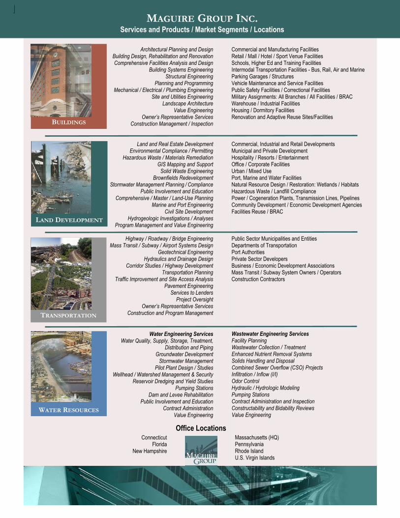
Commercial and Manufacturing Facilities Retail / Mall / Hotel / Sport Venue Facilities Schools, Higher Ed and Training Facilities Intermodal Transportation Facilities - Bus, Rail, Air and Marine Parking Garages / Structures Vehicle Maintenance and Service Facilities Public Safety Facilities / Correctional Facilities Military Assignments: All Branches / All Facilities / BRAC Warehouse / Industrial Facilities Housing / Dormitory Facilities Renovation and Adaptive Reuse Sites/Facilities Commercial, Industrial and Retail Developments Municipal and Private Development Hospitality / Resorts / Entertainment Office / Corporate Facilities Urban / Mixed Use Port, Marine and Water Facilities Natural Resource Design / Restoration: Wetlands / Habitats Hazardous Waste / Landfill Compliance Power / Cogeneration Plants, Transmission Lines, Pipelines Community Development / Economic Development Agencies Facilities Reuse / BRAC Public Sector Municipalities and Entities Departments of Transportation Port Authorities Private Sector Developers Business / Economic Development Associations Mass Transit / Subway System Owners / Operators Construction Contractors
Wastewater Engineering Services Facility Planning Wastewater Collection / Treatment Enhanced Nutrient Removal Systems Solids Handling and Disposal Combined Sewer Overflow (CSO) Projects Infiltration / Inflow (I/I) Odor Control Hydraulic / Hydrologic Modeling Pumping Stations Contract Administration and Inspection Constructability and Bidability Reviews Value Engineering
Office Locations
BUILDINGS
TRANSPORTATION
WATER RESOURCES
LAND DEVELOPMENT
MAGUIRE GROUP INC. Services and Products / Market Segments / Locations
Massachusetts (HQ) Pennsylvania Rhode Island U.S. Virgin Islands
Connecticut Florida
New Hampshire

Innovation… Protection… Security I n f r a s t r u c t u r e f o r t h e r e a l w o r l d .
Water Resources is dedicated to providing clients with the best, most innovative and cost-effective solutions. We established a position as a local leader in the water field by combining technical innovation and practical solutions that control capital expenditures and mitigate the impact of regulatory initiatives or compliance actions. No matter how large or small, our clients receive satisfying solutions.
Maguire takes pride in the ground-breaking work that becomes the industry standard for years to come, in both our water and wastewater groups. We offer technical and planning services to support integrated resources planning, water supply development and management, pollution control, ecosystem restoration, and wetlands and watershed management. Our water experts help clients protect water at its source, deliver water to homes and businesses, and collect and treat wastewater before reintroducing it safely into the environment.
Maguire’s water-related services have grown to encompass energy conservation issues, rate analysis and municipal advocacy as well as value engineering and construction engineering. Our experienced staff works with towns, cities, and districts throughout the Eastern Seaboard and the U.S. Virgin Islands to protect water resources, provide safe drinking water, and assure the public health through effective wastewater treatment. From planning through design, construction, and operations and management, we help clients meet the challenges they face in providing water services.
WATER RESOURCES
M a g u i r e G r o u p I n c . Architects / Engineers / Planners
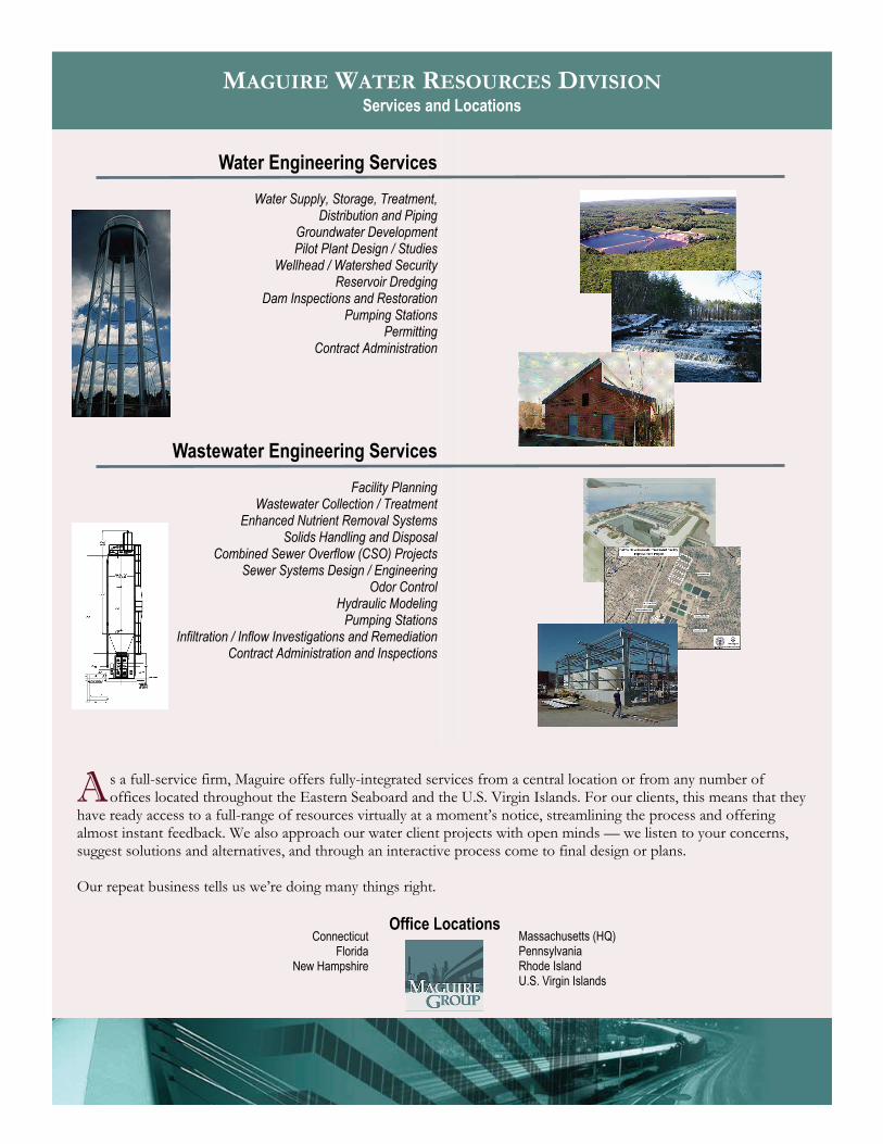
A s a full-service firm, Maguire offers fully-integrated services from a central location or from any number of offices located throughout the Eastern Seaboard and the U.S. Virgin Islands. For our clients, this means that they
have ready access to a full-range of resources virtually at a moment’s notice, streamlining the process and offering almost instant feedback. We also approach our water client projects with open minds — we listen to your concerns, suggest solutions and alternatives, and through an interactive process come to final design or plans. Our repeat business tells us we’re doing many things right.
MAGUIRE WATER RESOURCES DIVISION Services and Locations
Office Locations
Water Engineering Services
Water Supply, Storage, Treatment,
Distribution and Piping Groundwater Development Pilot Plant Design / Studies
Wellhead / Watershed Security Reservoir Dredging
Dam Inspections and Restoration Pumping Stations
Permitting Contract Administration
Wastewater Engineering Services
Facility Planning Wastewater Collection / Treatment
Enhanced Nutrient Removal Systems Solids Handling and Disposal
Combined Sewer Overflow (CSO) Projects Sewer Systems Design / Engineering
Odor Control Hydraulic Modeling
Pumping Stations Infiltration / Inflow Investigations and Remediation
Contract Administration and Inspections
Massachusetts (HQ) Pennsylvania Rhode Island U.S. Virgin Islands
Connecticut Florida
New Hampshire

Energy/Industrial Facilities Management Central Chilling/Heating Plants Coal-Electric Generation Units Cogeneration Communications/Control/SCADA Systems Distribution Automation Fluidized Bed Combustion Systems Gas, Oil, and Diesel-Driven Generators Heating, Venting and Air Conditioning Industrial and Institutional Utilities Instrumentation and Controls Plant Inspection and Evaluations Steam-Electric Generation Plants/ Substations Utility Distribution/Mapping Systems Utility Master Planning Studies
Environmental Asbestos and Lead Paint Surveys Air Quality Permitting and Modeling Biological Resources Studies Brownfield Investigation and Development Chemical and Ecological Risk Assessments Environmental Site Assessment/Impact Statements, Audits and Permitting Hazardous and Solid Waste Management Land Reclamation Landfill Design/Closing/Compliance Municipal and Industrial Waste Treatment Noise Control/Reduction Noise Modeling and Monitoring Odor Control Pollution Prevention/Abatement/Control Regulatory Strategies and Compliance Remedial Action Management Siting Studies Solid Waste Management Spill Prevention/Control/Countermeasure Plans (SPCC) Storage Tank Site Investigations/ Corrective Action Stormwater Measurement/Management Stream/Watershed Modeling Training on Regulatory Requirements Transactional Assessments Water Pollution Control/Treatment Wetland Delineation, Studies, and Mitigation Zoning Updates
Facilities Architectural Buildings Design/Engineering Building Inspections and Evaluations Building Specialty Systems • Security Access Control • Fire Detection and Alarm • Network and Communication Clean Rooms
Facilities (Continued) Facility Master Planning Historic Preservation HVAC System Studies and Upgrades Industrial/Commercial Buildings Design Industrial Process Facilities MEP Systems: Mechanical/Electrical/Plumbing Plant Inspection and Evaluations Structural Design and Engineering
Infrastructure Building Expansion and Renovation Combined Sewer Overflow (CSO) Services Commercial/Manufacturing/Warehouse/ Distribution Facilities Community Centers Correctional Facilities Dams and Reservoirs Educational Facilities Ferry Terminals Geotechnical Engineering Intermodal Transportation Facilities Land Development Mass Transit/Subway/Airport Systems Military Facilities and Airports Municipal Office Buildings—Town Halls Navigation Lock and Dam Rehabilitation Parks and Recreation Parking Garages and Structures Piers and Jetties Ports, Harbors and Marinas Public Safety Facilities Renovation and Adaptive Reuse Sites/Facilities Runway Extensions Schools/Universities/Housing Site Utilities/Development Sports/Entertainment Venues Surveying and Mapping Vehicle Maintenance/Service Facilities Water and Wastewater Engineering Waterfront Development Wellhead/Watershed Management/Security
Land Development/ Resource Management Casino and Resort Development Commercial/Residential Site Development Community Planning/Development Design Build Services Downtown Beautification/Reuse Programs Flood Protection and Control Hotels and Resorts Industrial/Business Park Complexes Irrigation and Drainage Natural Resource Management Parks, Open Space and Recreation Retail/Mall Development Urban and Regional Planning Waterfront/Marinas Wetlands Strategies
Management Constructability and Bidability Reviews Construction Management Contract Administration/Inspections Contractor Procurement Cost Estimating and Control Design-Build Oversight Funding Application Support Expert Witness MCPPO-Certified Professional Services Operations & Maintenance (O&M) Services Owner’s Project Mgmt. (OPM) Services Program/Project Management & Oversight Public Involvement and Education Start-up and Operator Training Technical Management Value Engineering
Planning, Design and Studies Architectural Design Comprehensive/Master/Land-use Planning Computer-Aided Design/Drafting (CADD) Design-Build Engineering Electrical Design Engineering Design Engineering Feasibility Studies Environmental Studies GIS Planning Landscape Architecture Mechanical Design Site Selection Evaluations & Site Planning Structural Design Surveying and Mapping Transportation Engineering & Planning Urban and Regional Planning Programs Utility Planning
Transportation Expressways/Interchanges/Interstates Highways, Roads, Streets and Bridges Traffic Control and Signalization Transit Systems Transportation Engineering and Planning
Water Resources CSO Services Dams and Reservoirs Enhanced Nutrient Removal (ENR) Systems Hydraulics and Drainage Design & Modeling Hydrogeologic Investigations Groundwater Development Infiltration/Inflow Modeling (I/I) Pilot Plant Design/Studies Pumping Stations Wastewater Collection/Treatment/Reuse WWTP Design and Engineering Water Quality/Supply/Treatment/Storage/ Distribution and Piping Wellhead/Watershed Management and Security
PORTFOLIO: Professional Services and Project Types www.maguiregroup.com
i n f r a s t r u c t u r e for the real world


MAG
UIR
E G
RO
UP, IN
TAB
LE O
F C
ON
TEN
TS
C
.
Section I Company Overview Section II Water Engineering Section III Wastewater Engineering Section IV Dam Engineering

MAG
UIR
E G
RO
UP, IN
WATER
EN
GIN
EER
ING
C
.
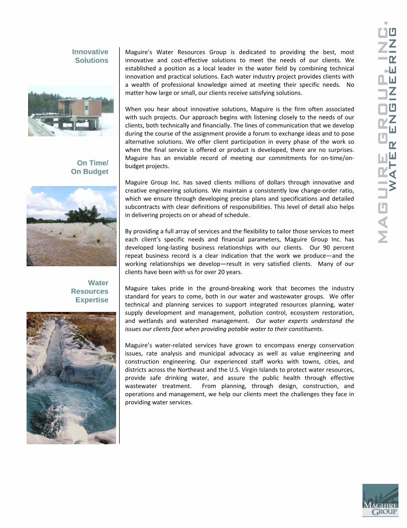
Maguire’s Water Resources Group is dedicated to providing the best, most innovative and cost‐effective solutions to meet the needs of our clients. We established a position as a local leader in the water field by combining technical innovation and practical solutions. Each water industry project provides clients with a wealth of professional knowledge aimed at meeting their specific needs. No matter how large or small, our clients receive satisfying solutions. When you hear about innovative solutions, Maguire is the firm often associated with such projects. Our approach begins with listening closely to the needs of our clients, both technically and financially. The lines of communication that we develop during the course of the assignment provide a forum to exchange ideas and to pose alternative solutions. We offer client participation in every phase of the work so when the final service is offered or product is developed, there are no surprises. Maguire has an enviable record of meeting our commitments for on‐time/on‐budget projects. Maguire Group Inc. has saved clients millions of dollars through innovative and creative engineering solutions. We maintain a consistently low change‐order ratio, which we ensure through developing precise plans and specifications and detailed subcontracts with clear definitions of responsibilities. This level of detail also helps in delivering projects on or ahead of schedule. By providing a full array of services and the flexibility to tailor those services to meet each client’s specific needs and financial parameters, Maguire Group Inc. has developed long‐lasting business relationships with our clients. Our 90 percent repeat business record is a clear indication that the work we produce—and the working relationships we develop—result in very satisfied clients. Many of our clients have been with us for over 20 years. Maguire takes pride in the ground‐breaking work that becomes the industry standard for years to come, both in our water and wastewater groups. We offer technical and planning services to support integrated resources planning, water supply development and management, pollution control, ecosystem restoration, and wetlands and watershed management. Our water experts understand the issues our clients face when providing potable water to their constituents. Maguire’s water‐related services have grown to encompass energy conservation issues, rate analysis and municipal advocacy as well as value engineering and construction engineering. Our experienced staff works with towns, cities, and districts across the Northeast and the U.S. Virgin Islands to protect water resources, provide safe drinking water, and assure the public health through effective wastewater treatment. From planning, through design, construction, and operations and management, we help our clients meet the challenges they face in providing water services.
Innovative Solutions
On Time/ On Budget
Water Resources
Expertise
MAG
UIR
E G
RO
UP, IN
C.
WATER
EN
GIN
EER
ING
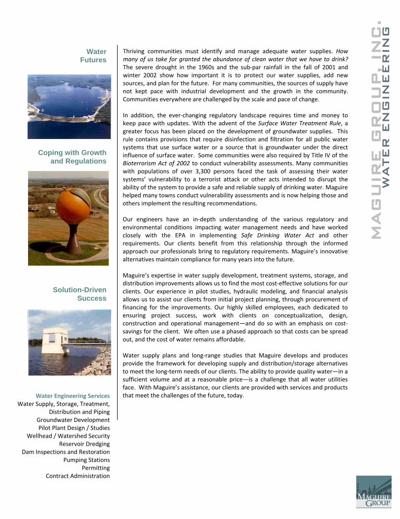
Thriving communities must identify and manage adequate water supplies. How many of us take for granted the abundance of clean water that we have to drink? The severe drought in the 1960s and the sub‐par rainfall in the fall of 2001 and winter 2002 show how important it is to protect our water supplies, add new sources, and plan for the future. For many communities, the sources of supply have not kept pace with industrial development and the growth in the community. Communities everywhere are challenged by the scale and pace of change. In addition, the ever‐changing regulatory landscape requires time and money to keep pace with updates. With the advent of the Surface Water Treatment Rule, a greater focus has been placed on the development of groundwater supplies. This rule contains provisions that require disinfection and filtration for all public water systems that use surface water or a source that is groundwater under the direct influence of surface water. Some communities were also required by Title IV of the Bioterrorism Act of 2002 to conduct vulnerability assessments. Many communities with populations of over 3,300 persons faced the task of assessing their water systems’ vulnerability to a terrorist attack or other acts intended to disrupt the ability of the system to provide a safe and reliable supply of drinking water. Maguire helped many towns conduct vulnerability assessments and is now helping those and others implement the resulting recommendations. Our engineers have an in‐depth understanding of the various regulatory and environmental conditions impacting water management needs and have worked closely with the EPA in implementing Safe Drinking Water Act and other requirements. Our clients benefit from this relationship through the informed approach our professionals bring to regulatory requirements. Maguire’s innovative alternatives maintain compliance for many years into the future. Maguire’s expertise in water supply development, treatment systems, storage, and distribution improvements allows us to find the most cost‐effective solutions for our clients. Our experience in pilot studies, hydraulic modeling, and financial analysis allows us to assist our clients from initial project planning, through procurement of financing for the improvements. Our highly skilled employees, each dedicated to ensuring project success, work with clients on conceptualization, design, construction and operational management—and do so with an emphasis on cost‐savings for the client. We often use a phased approach so that costs can be spread out, and the cost of water remains affordable. Water supply plans and long‐range studies that Maguire develops and produces provide the framework for developing supply and distribution/storage alternatives to meet the long‐term needs of our clients. The ability to provide quality water—in a sufficient volume and at a reasonable price—is a challenge that all water utilities face. With Maguire’s assistance, our clients are provided with services and products that meet the challenges of the future, today.
Water Futures
Coping with Growth and Regulations
Solution-Driven Success
Water Engineering Services Water Supply, Storage, Treatment,
Distribution and Piping Groundwater Development Pilot Plant Design / Studies
Wellhead / Watershed Security Reservoir Dredging
Dam Inspections and Restoration Pumping Stations
Permitting Contract Administration
C.
MAG
UIR
E G
RO
UP, IN
WATER
EN
GIN
EER
ING
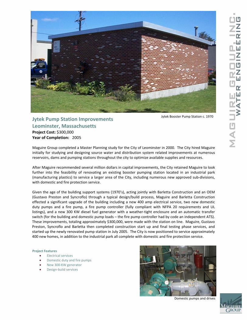
Jytek Pump Station Improvements Leominster, Massachusetts Project Cost: $300,000 Year of Completion: 2005 Maguire Group completed a Master Planning study for the City of Leominster in 2000. The City hired Maguire initially for studying and designing source water and distribution system related improvements at numerous reservoirs, dams and pumping stations throughout the city to optimize available supplies and resources. After Maguire recommended several million dollars in capital improvements, the City retained Maguire to look further into the feasibility of renovating an existing booster pumping station located in an industrial park (manufacturing plastics) to service a larger area of the City, including numerous new approved sub‐divisions, with domestic and fire protection service. Given the age of the building support systems (1970’s), acting jointly with Barletta Construction and an OEM (Gustavo Preston and Syncroflo) through a typical design/build process, Maguire and Barletta Construction effected a significant upgrade of the building including a new 400 amp electrical service, two new domestic duty pumps and a fire pump, a fire pump controller (fully compliant with NFPA 20 requirements and UL listings), and a new 300 KW diesel fuel generator with a weather‐tight enclosure and an automatic transfer switch (for the building and domestic pump loads – the fire pump controller had by code an independent ATS). These improvements, totaling approximately $300,000, were made with the station on line. Maguire, Gustavo Preston, Syncroflo and Barletta then completed construction start up and final testing phase services, and started up the newly renovated pump station in July 2005. The City is now positioned to service approximately 400 new homes, in addition to the industrial park all complete with domestic and fire protection service.
Project Features • Electrical services • Domestic duty and fire pumps • New 300‐KW generator • Design‐build services
Jytek Booster Pump Station c. 1970
Domestic pumps and drives
C.
MAG
UIR
E G
RO
UP, IN
WATER
EN
GIN
EER
ING
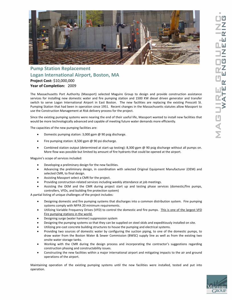
Pump Station Replacement Logan International Airport, Boston, MA Project Cost: $10,000,000 Year of Completion: 2009 The Massachusetts Port Authority (Massport) selected Maguire Group to design and provide construction assistance services for installing new domestic water and fire pumping station and 1500 KW diesel driven generator and transfer switch to serve Logan International Airport in East Boston. The new facilities are replacing the existing Prescott St. Pumping Station that had been in operation since 1951. Recent changes in the Massachusetts statutes allow Massport to use the Construction Management at Risk delivery process for the project.
Since the existing pumping systems were nearing the end of their useful life, Massport wanted to install new facilities that would be more technologically advanced and capable of meeting future water demands more efficiently.
The capacities of the new pumping facilities are:
• Domestic pumping station: 3,000 gpm @ 90 psig discharge.
• Fire pumping station: 8,500 gpm @ 90 psi discharge.
• Combined station output (determined at start‐up testing): 8,300 gpm @ 90 psig discharge without all pumps on. More flow was possible but limited by amount of fire hydrants that could be opened at the airport.
Maguire’s scope of services included:
• Developing a preliminary design for the new facilities. • Advancing the preliminary design, in coordination with selected Original Equipment Manufacturer (OEM) and
selected CMR, to final design. • Assisting Massport select a CMR for the project. • Providing construction‐related services including weekly attendance at job meetings. • Assisting the OEM and the CMR during project start up and testing phase services (domestic/fire pumps,
controllers, VFDs, and building fire protection system) A partial listing of unique challenges of the project includes:
• Designing domestic and fire pumping systems that discharges into a common distribution system. Fire pumping systems comply with NFPA 20 minimum requirements.
• Utilizing Variable Frequency Drives (VFD) to control the domestic and fire pumps. This is one of the largest VFD Fire pumping stations in the world.
• Designing surge (water hammer) suppression system • Designing the pumping systems so that they can be supplied on steel skids and expeditiously installed on site. • Utilizing pre‐cast concrete building structures to house the pumping and electrical systems. • Providing two sources of domestic water by configuring the suction piping, to one of the domestic pumps, to
draw water from the Boston Water & Sewer Commission (BWSC) supply line as well as from the existing two onsite water storage tanks.
• Working with the CMR during the design process and incorporating the contractor’s suggestions regarding construction phasing and constructability issues.
• Constructing the new facilities within a major international airport and mitigating impacts to the air and ground operations of the airport.
Maintaining operation of the existing pumping systems until the new facilities were installed, tested and put into operation.
C.
MAG
UIR
E G
RO
UP, IN
WATER
EN
GIN
EER
ING
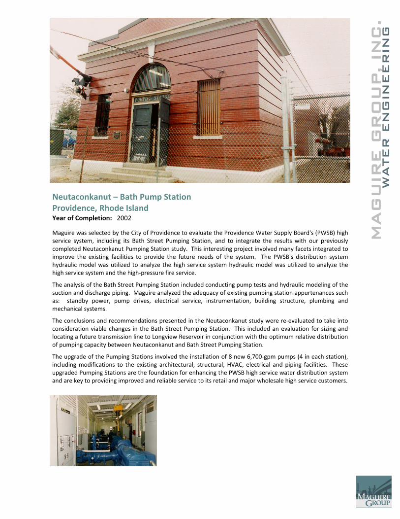
Neutaconkanut – Bath Pump Station Providence, Rhode Island Year of Completion: 2002
Maguire was selected by the City of Providence to evaluate the Providence Water Supply Board's (PWSB) high service system, including its Bath Street Pumping Station, and to integrate the results with our previously completed Neutaconkanut Pumping Station study. This interesting project involved many facets integrated to improve the existing facilities to provide the future needs of the system. The PWSB's distribution system hydraulic model was utilized to analyze the high service system hydraulic model was utilized to analyze the high service system and the high‐pressure fire service.
The analysis of the Bath Street Pumping Station included conducting pump tests and hydraulic modeling of the suction and discharge piping. Maguire analyzed the adequacy of existing pumping station appurtenances such as: standby power, pump drives, electrical service, instrumentation, building structure, plumbing and mechanical systems.
The conclusions and recommendations presented in the Neutaconkanut study were re‐evaluated to take into consideration viable changes in the Bath Street Pumping Station. This included an evaluation for sizing and locating a future transmission line to Longview Reservoir in conjunction with the optimum relative distribution of pumping capacity between Neutaconkanut and Bath Street Pumping Station.
The upgrade of the Pumping Stations involved the installation of 8 new 6,700‐gpm pumps (4 in each station), including modifications to the existing architectural, structural, HVAC, electrical and piping facilities. These upgraded Pumping Stations are the foundation for enhancing the PWSB high service water distribution system and are key to providing improved and reliable service to its retail and major wholesale high service customers.
C.
MAG
UIR
E G
RO
UP, IN
WATER
EN
GIN
EER
ING
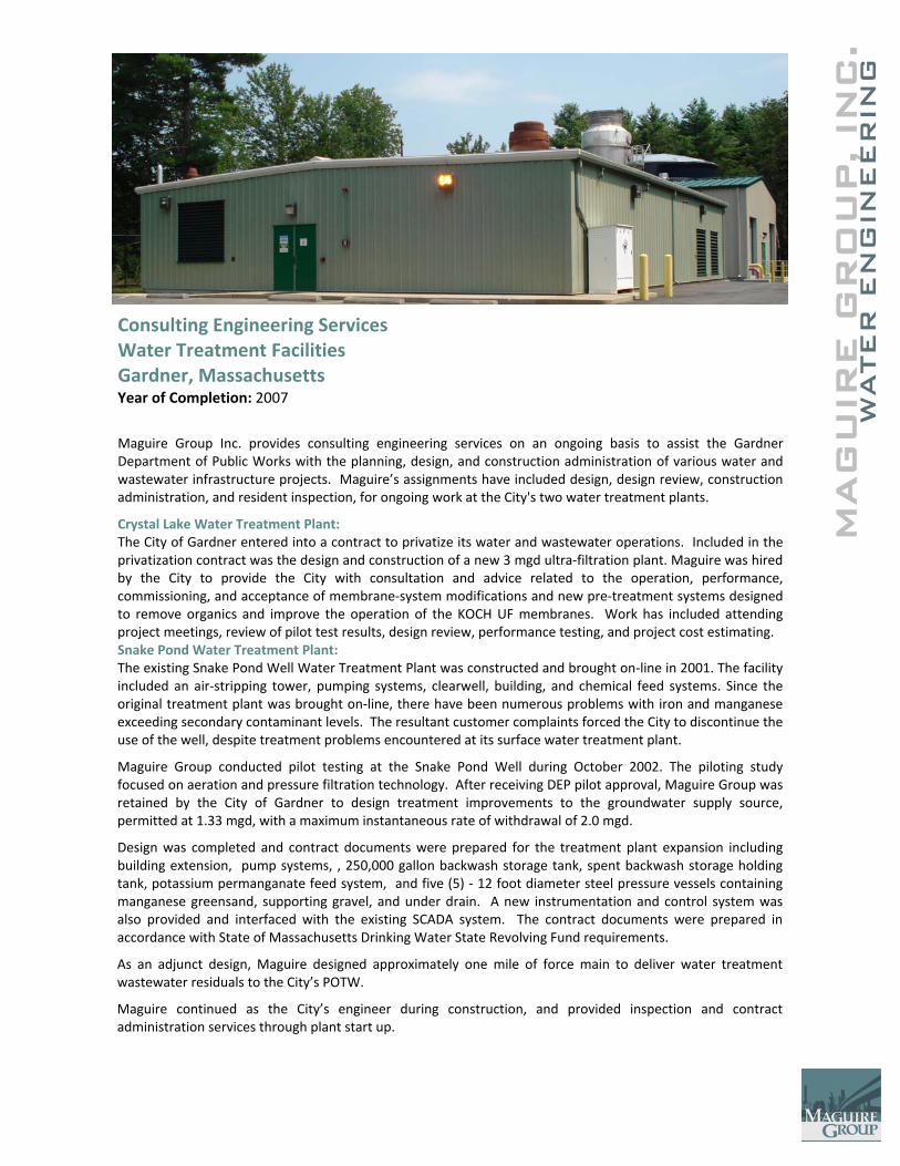
Consulting Engineering Services Water Treatment Facilities Gardner, Massachusetts Year of Completion: 2007
Maguire Group Inc. provides consulting engineering services on an ongoing basis to assist the Gardner Department of Public Works with the planning, design, and construction administration of various water and wastewater infrastructure projects. Maguire’s assignments have included design, design review, construction administration, and resident inspection, for ongoing work at the City's two water treatment plants.
Crystal Lake Water Treatment Plant: The City of Gardner entered into a contract to privatize its water and wastewater operations. Included in the privatization contract was the design and construction of a new 3 mgd ultra‐filtration plant. Maguire was hired by the City to provide the City with consultation and advice related to the operation, performance, commissioning, and acceptance of membrane‐system modifications and new pre‐treatment systems designed to remove organics and improve the operation of the KOCH UF membranes. Work has included attending project meetings, review of pilot test results, design review, performance testing, and project cost estimating. Snake Pond Water Treatment Plant: The existing Snake Pond Well Water Treatment Plant was constructed and brought on‐line in 2001. The facility included an air‐stripping tower, pumping systems, clearwell, building, and chemical feed systems. Since the original treatment plant was brought on‐line, there have been numerous problems with iron and manganese exceeding secondary contaminant levels. The resultant customer complaints forced the City to discontinue the use of the well, despite treatment problems encountered at its surface water treatment plant.
Maguire Group conducted pilot testing at the Snake Pond Well during October 2002. The piloting study focused on aeration and pressure filtration technology. After receiving DEP pilot approval, Maguire Group was retained by the City of Gardner to design treatment improvements to the groundwater supply source, permitted at 1.33 mgd, with a maximum instantaneous rate of withdrawal of 2.0 mgd.
Design was completed and contract documents were prepared for the treatment plant expansion including building extension, pump systems, , 250,000 gallon backwash storage tank, spent backwash storage holding tank, potassium permanganate feed system, and five (5) ‐ 12 foot diameter steel pressure vessels containing manganese greensand, supporting gravel, and under drain. A new instrumentation and control system was also provided and interfaced with the existing SCADA system. The contract documents were prepared in accordance with State of Massachusetts Drinking Water State Revolving Fund requirements.
As an adjunct design, Maguire designed approximately one mile of force main to deliver water treatment wastewater residuals to the City’s POTW.
Maguire continued as the City’s engineer during construction, and provided inspection and contract administration services through plant start up.
C.
MAG
UIR
E G
RO
UP, IN
WATER
EN
GIN
EER
ING
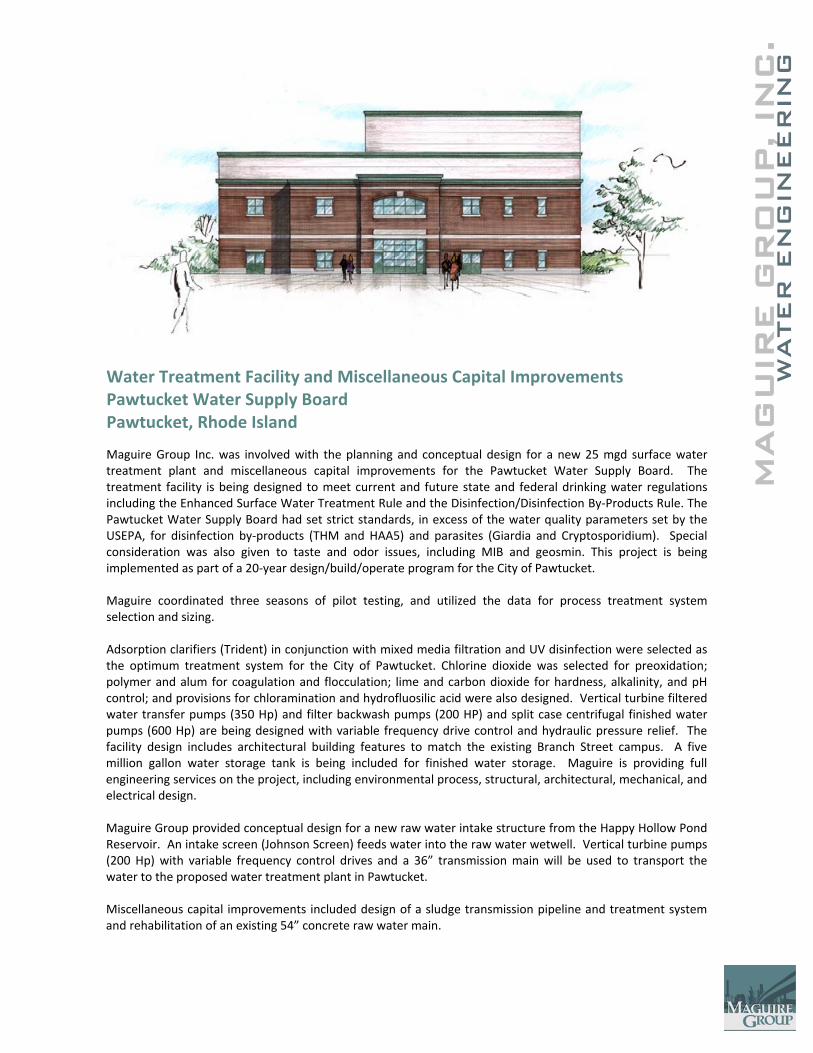
Water Treatment Facility and Miscellaneous Capital Improvements Pawtucket Water Supply Board Pawtucket, Rhode Island
Maguire Group Inc. was involved with the planning and conceptual design for a new 25 mgd surface water treatment plant and miscellaneous capital improvements for the Pawtucket Water Supply Board. The treatment facility is being designed to meet current and future state and federal drinking water regulations including the Enhanced Surface Water Treatment Rule and the Disinfection/Disinfection By‐Products Rule. The Pawtucket Water Supply Board had set strict standards, in excess of the water quality parameters set by the USEPA, for disinfection by‐products (THM and HAA5) and parasites (Giardia and Cryptosporidium). Special consideration was also given to taste and odor issues, including MIB and geosmin. This project is being implemented as part of a 20‐year design/build/operate program for the City of Pawtucket. Maguire coordinated three seasons of pilot testing, and utilized the data for process treatment system selection and sizing. Adsorption clarifiers (Trident) in conjunction with mixed media filtration and UV disinfection were selected as the optimum treatment system for the City of Pawtucket. Chlorine dioxide was selected for preoxidation; polymer and alum for coagulation and flocculation; lime and carbon dioxide for hardness, alkalinity, and pH control; and provisions for chloramination and hydrofluosilic acid were also designed. Vertical turbine filtered water transfer pumps (350 Hp) and filter backwash pumps (200 HP) and split case centrifugal finished water pumps (600 Hp) are being designed with variable frequency drive control and hydraulic pressure relief. The facility design includes architectural building features to match the existing Branch Street campus. A five million gallon water storage tank is being included for finished water storage. Maguire is providing full engineering services on the project, including environmental process, structural, architectural, mechanical, and electrical design. Maguire Group provided conceptual design for a new raw water intake structure from the Happy Hollow Pond Reservoir. An intake screen (Johnson Screen) feeds water into the raw water wetwell. Vertical turbine pumps (200 Hp) with variable frequency control drives and a 36” transmission main will be used to transport the water to the proposed water treatment plant in Pawtucket. Miscellaneous capital improvements included design of a sludge transmission pipeline and treatment system and rehabilitation of an existing 54” concrete raw water main.
C.
MAG
UIR
E G
RO
UP, IN
WATER
EN
GIN
EER
ING
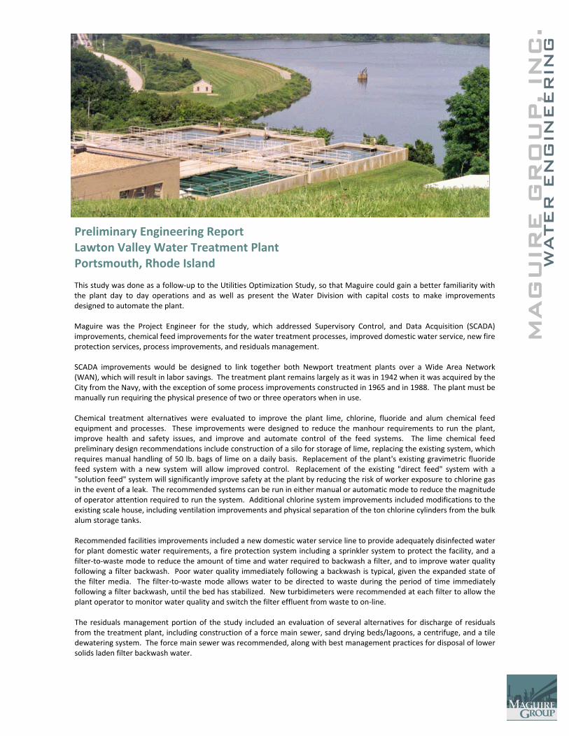
Preliminary Engineering Report Lawton Valley Water Treatment Plant Portsmouth, Rhode Island This study was done as a follow‐up to the Utilities Optimization Study, so that Maguire could gain a better familiarity with the plant day to day operations and as well as present the Water Division with capital costs to make improvements designed to automate the plant. Maguire was the Project Engineer for the study, which addressed Supervisory Control, and Data Acquisition (SCADA) improvements, chemical feed improvements for the water treatment processes, improved domestic water service, new fire protection services, process improvements, and residuals management. SCADA improvements would be designed to link together both Newport treatment plants over a Wide Area Network (WAN), which will result in labor savings. The treatment plant remains largely as it was in 1942 when it was acquired by the City from the Navy, with the exception of some process improvements constructed in 1965 and in 1988. The plant must be manually run requiring the physical presence of two or three operators when in use. Chemical treatment alternatives were evaluated to improve the plant lime, chlorine, fluoride and alum chemical feed equipment and processes. These improvements were designed to reduce the manhour requirements to run the plant, improve health and safety issues, and improve and automate control of the feed systems. The lime chemical feed preliminary design recommendations include construction of a silo for storage of lime, replacing the existing system, which requires manual handling of 50 lb. bags of lime on a daily basis. Replacement of the plant's existing gravimetric fluoride feed system with a new system will allow improved control. Replacement of the existing "direct feed" system with a "solution feed" system will significantly improve safety at the plant by reducing the risk of worker exposure to chlorine gas in the event of a leak. The recommended systems can be run in either manual or automatic mode to reduce the magnitude of operator attention required to run the system. Additional chlorine system improvements included modifications to the existing scale house, including ventilation improvements and physical separation of the ton chlorine cylinders from the bulk alum storage tanks. Recommended facilities improvements included a new domestic water service line to provide adequately disinfected water for plant domestic water requirements, a fire protection system including a sprinkler system to protect the facility, and a filter‐to‐waste mode to reduce the amount of time and water required to backwash a filter, and to improve water quality following a filter backwash. Poor water quality immediately following a backwash is typical, given the expanded state of the filter media. The filter‐to‐waste mode allows water to be directed to waste during the period of time immediately following a filter backwash, until the bed has stabilized. New turbidimeters were recommended at each filter to allow the plant operator to monitor water quality and switch the filter effluent from waste to on‐line. The residuals management portion of the study included an evaluation of several alternatives for discharge of residuals from the treatment plant, including construction of a force main sewer, sand drying beds/lagoons, a centrifuge, and a tile dewatering system. The force main sewer was recommended, along with best management practices for disposal of lower solids laden filter backwash water.
C.
MAG
UIR
E G
RO
UP, IN
WATER
EN
GIN
EER
ING
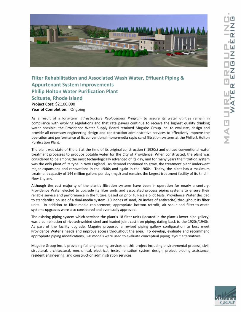
Filter Rehabilitation and Associated Wash Water, Effluent Piping & Appurtenant System Improvements Philip Holton Water Purification Plant Scituate, Rhode Island Project Cost: $2,100,000 Year of Completion: Ongoing
As a result of a long‐term Infrastructure Replacement Program to assure its water utilities remain in compliance with evolving regulations and that rate payers continue to receive the highest quality drinking water possible, the Providence Water Supply Board retained Maguire Group Inc. to evaluate, design and provide all necessary engineering design and construction administrative services to effectively improve the operation and performance of its conventional mono‐media rapid sand filtration systems at the Philip J. Holton Purification Plant.
The plant was state‐of‐the‐art at the time of its original construction (~1920s) and utilizes conventional water treatment processes to produce potable water for the City of Providence. When constructed, the plant was considered to be among the most technologically advanced of its day, and for many years the filtration system was the only plant of its type in New England. As demand continued to grow, the treatment plant underwent major expansions and renovations in the 1940s and again in the 1960s. Today, the plant has a maximum treatment capacity of 144 million gallons per day (mgd) and remains the largest treatment facility of its kind in New England.
Although the vast majority of the plant’s filtration systems have been in operation for nearly a century, Providence Water elected to upgrade its filter units and associated process piping systems to ensure their reliable service and performance in the future. Based on prior full‐scale pilot tests, Providence Water decided to standardize on use of a dual‐media system (10 inches of sand, 20 inches of anthracite) throughout its filter units. In addition to filter media replacement, appropriate bottom retrofit, air scour and filter‐to‐waste systems upgrades were also considered and eventually approved.
The existing piping system which serviced the plant’s 18 filter units (located in the plant’s lower pipe gallery) was a combination of riveted/welded steel and leaded‐joint cast‐iron piping, dating back to the 1920s/1940s. As part of the facility upgrade, Maguire proposed a revised piping gallery configuration to best meet Providence Water’s needs and improve access throughout the area. To develop, evaluate and recommend appropriate piping modifications, 3‐D models were used to evaluate conceptual piping layout alternatives. Maguire Group Inc. is providing full engineering services on this project including environmental process, civil, structural, architectural, mechanical, electrical, instrumentation system design, project bidding assistance, resident engineering, and construction administration services.
C.
MAG
UIR
E G
RO
UP, IN
WATER
EN
GIN
EER
ING
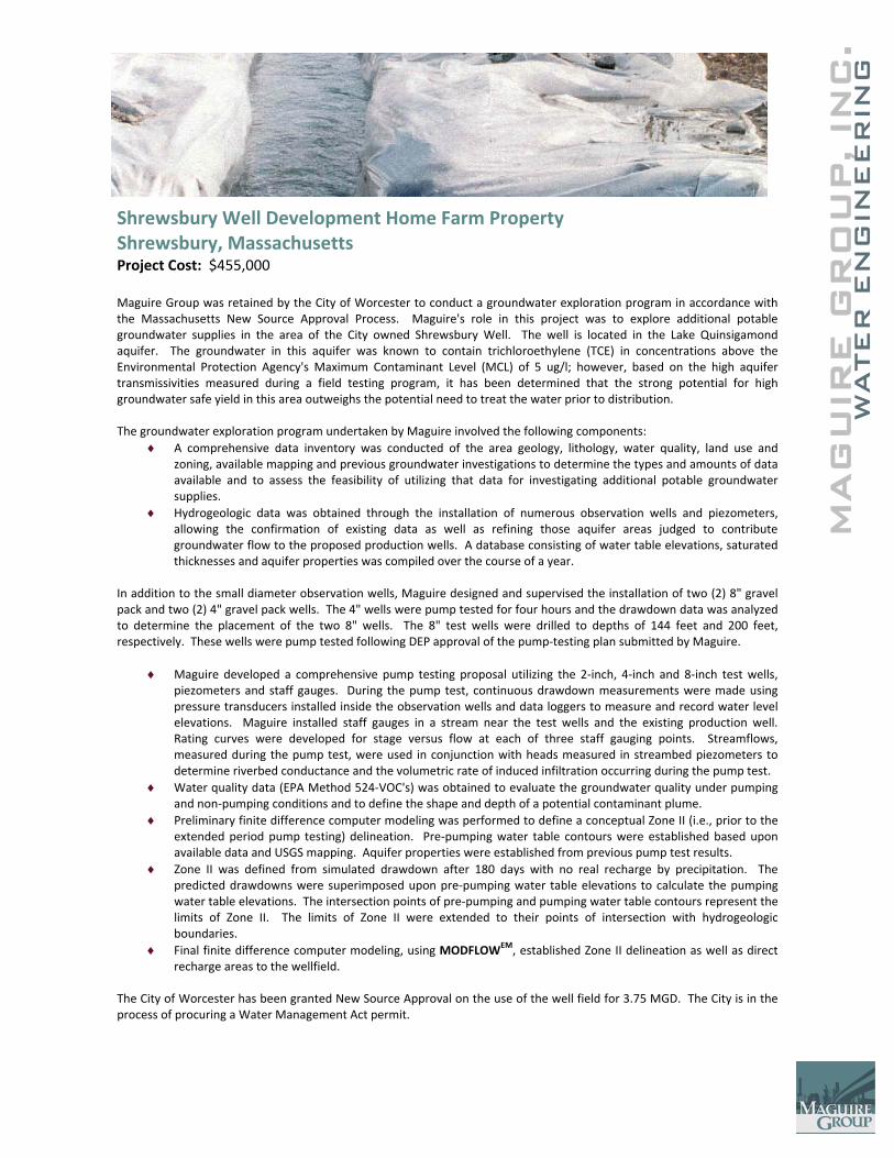
Shrewsbury Well Development Home Farm Property Shrewsbury, Massachusetts Project Cost: $455,000 Maguire Group was retained by the City of Worcester to conduct a groundwater exploration program in accordance with the Massachusetts New Source Approval Process. Maguire's role in this project was to explore additional potable groundwater supplies in the area of the City owned Shrewsbury Well. The well is located in the Lake Quinsigamond aquifer. The groundwater in this aquifer was known to contain trichloroethylene (TCE) in concentrations above the Environmental Protection Agency's Maximum Contaminant Level (MCL) of 5 ug/l; however, based on the high aquifer transmissivities measured during a field testing program, it has been determined that the strong potential for high groundwater safe yield in this area outweighs the potential need to treat the water prior to distribution. The groundwater exploration program undertaken by Maguire involved the following components:
♦ A comprehensive data inventory was conducted of the area geology, lithology, water quality, land use and zoning, available mapping and previous groundwater investigations to determine the types and amounts of data available and to assess the feasibility of utilizing that data for investigating additional potable groundwater supplies.
♦ Hydrogeologic data was obtained through the installation of numerous observation wells and piezometers, allowing the confirmation of existing data as well as refining those aquifer areas judged to contribute groundwater flow to the proposed production wells. A database consisting of water table elevations, saturated thicknesses and aquifer properties was compiled over the course of a year.
In addition to the small diameter observation wells, Maguire designed and supervised the installation of two (2) 8" gravel pack and two (2) 4" gravel pack wells. The 4" wells were pump tested for four hours and the drawdown data was analyzed to determine the placement of the two 8" wells. The 8" test wells were drilled to depths of 144 feet and 200 feet, respectively. These wells were pump tested following DEP approval of the pump‐testing plan submitted by Maguire.
♦ Maguire developed a comprehensive pump testing proposal utilizing the 2‐inch, 4‐inch and 8‐inch test wells, piezometers and staff gauges. During the pump test, continuous drawdown measurements were made using pressure transducers installed inside the observation wells and data loggers to measure and record water level elevations. Maguire installed staff gauges in a stream near the test wells and the existing production well. Rating curves were developed for stage versus flow at each of three staff gauging points. Streamflows, measured during the pump test, were used in conjunction with heads measured in streambed piezometers to determine riverbed conductance and the volumetric rate of induced infiltration occurring during the pump test.
♦ Water quality data (EPA Method 524‐VOC's) was obtained to evaluate the groundwater quality under pumping and non‐pumping conditions and to define the shape and depth of a potential contaminant plume.
♦ Preliminary finite difference computer modeling was performed to define a conceptual Zone II (i.e., prior to the extended period pump testing) delineation. Pre‐pumping water table contours were established based upon available data and USGS mapping. Aquifer properties were established from previous pump test results.
♦ Zone II was defined from simulated drawdown after 180 days with no real recharge by precipitation. The predicted drawdowns were superimposed upon pre‐pumping water table elevations to calculate the pumping water table elevations. The intersection points of pre‐pumping and pumping water table contours represent the limits of Zone II. The limits of Zone II were extended to their points of intersection with hydrogeologic boundaries.
♦ Final finite difference computer modeling, using MODFLOWEM, established Zone II delineation as well as direct recharge areas to the wellfield.
The City of Worcester has been granted New Source Approval on the use of the well field for 3.75 MGD. The City is in the process of procuring a Water Management Act permit.

C.
MAG
UIR
E G
RO
UP, IN
WATER
EN
GIN
EER
ING
Initial Individual Water Supply Plan and Master Plan East Hampton, Connecticut Project Cost: $350,000 Year of Completion: 2005 A significant event in the history of the East Hampton municipal water system occurred on January 6, 2003 when the State directed the Town of East Hampton to prepare an Initial Water Supply Plan. On January 6, 2003 the Town received a Compliance Order from the Connecticut Department of Public Health, Drinking Water Section, to submit, on or before November 19, 2004, an “Initial Individual Water Supply Plan (IWSP)”. This order was duly authorized under State of Connecticut Statues and necessitated compliance to avoid civil penalties of “not to exceed $5,000.00 per day”. The impetus behind this order was the Health Department’s acceptance of the Southeastern Connecticut’s Water Utility Coordinating Committee Report in which the Town of East Hampton was named one of three “Exclusive Service Area Providers” for the Town. The preparation of this IWSP for the Town included these major components: “Well Site Approvals”, “Source Safe Yield Analysis”, “Siting Analysis”, “Level A Mapping Plan of Data Collection and Analysis”, “Population Served”, “Present and Future Service Areas” “Land Use”, “Source Protection”, “Demand Projection”, “Emergency Contingency Plan”, “Water Conservation Plan”, “Capital Improvements” and “Financial Analysis”. In addition, a Water Supply Plan was prepared for the town’s existing Village Center System (2 wells, iron and manganese precipitation, carbon filtration, pumping, below grade clearwell and hydropneumatic storage tanks) serving 31 customers that was certified as a public water system by DPUC in the early 1990’s in response to private wells contamination.
Maguire Group’s focus was on completion of this State ordered Initial Individual Water Supply Plan and to simultaneously develop a Municipal Water System Master Plan identifying major capital infrastructure components (source, treatment, residuals disposal, transmission and distribution system piping, storage tanks, split zones) for a newly expanded “Centralized Water System” to eventually serve greater than 10,000 persons. The Master Plan included a comprehensive document which represents the Preliminary Engineering “Opinion of Probable Project Cost” for the East Hampton Municipal Water System Project. Buy‐in costs were assessed based upon an “Equivalent Metering Unit (EMU)”. This analysis assessed future number of connections (Phase I, II and III construction contracts), number of EMUs, portion of State and Federal Grants (CIAC), Annualized rate of inflation, short term and long term borrowing rates, construction schedule, uncollectibles, public safety assessment and portion of costs paid by future sales revenue. The analysis assessed operations costs and defined a “critical mass” of customers to make the centralized water system self‐sustaining.
Some of the reasons that ultimately lead to the CT Department of Public Health’s directive for the Town to prepare the IWSP are:
• Increasing frequency of groundwater contamination of individual on‐site wells • General Public health and safety concerns over groundwater pollution • Coliform Bacteria water quality issues associated with homes on the eastern side of Lake Pocotopaug • Business retention and economic revitalization of the Village Center; and • Quality of life • The Town’s firm position to obtain/retain its Exclusive Service Area rights to the entire Town of East Hampton and its
opposition to the Southeast Water Utility Coordinating Committee findings that the Town would have 3 Exclusive Service Area providers.
Final Water Supply Plan approval was granted in the spring of 2006 following CTDPH, CTDPUC and CTDEP comments. This Plan represents a blueprint for moving forward to expand the existing water ystem (31 customers) to the centralized system (5,000 customers).
Maguire successfully completed other work including an individual diversion permit, a flood management certification, Phase II Environmental Site Assessment, a Remedial Action Plan, and contract documents to remediate a soils contaminated site.
C.
MAG
UIR
E G
RO
UP, IN
WATER
EN
GIN
EER
ING
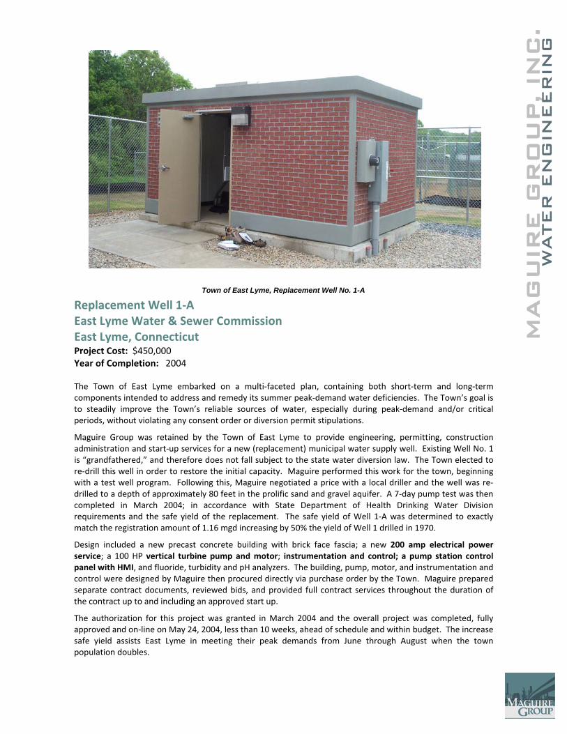
Replacement Well 1‐A East Lyme Water & Sewer Commission East Lyme, Connecticut Project Cost: $450,000 Year of Completion: 2004 The Town of East Lyme embarked on a multi‐faceted plan, containing both short‐term and long‐term components intended to address and remedy its summer peak‐demand water deficiencies. The Town’s goal is to steadily improve the Town’s reliable sources of water, especially during peak‐demand and/or critical periods, without violating any consent order or diversion permit stipulations.
Maguire Group was retained by the Town of East Lyme to provide engineering, permitting, construction administration and start‐up services for a new (replacement) municipal water supply well. Existing Well No. 1 is “grandfathered,” and therefore does not fall subject to the state water diversion law. The Town elected to re‐drill this well in order to restore the initial capacity. Maguire performed this work for the town, beginning with a test well program. Following this, Maguire negotiated a price with a local driller and the well was re‐drilled to a depth of approximately 80 feet in the prolific sand and gravel aquifer. A 7‐day pump test was then completed in March 2004; in accordance with State Department of Health Drinking Water Division requirements and the safe yield of the replacement. The safe yield of Well 1‐A was determined to exactly match the registration amount of 1.16 mgd increasing by 50% the yield of Well 1 drilled in 1970.
Design included a new precast concrete building with brick face fascia; a new 200 amp electrical power service; a 100 HP vertical turbine pump and motor; instrumentation and control; a pump station control panel with HMI, and fluoride, turbidity and pH analyzers. The building, pump, motor, and instrumentation and control were designed by Maguire then procured directly via purchase order by the Town. Maguire prepared separate contract documents, reviewed bids, and provided full contract services throughout the duration of the contract up to and including an approved start up.
The authorization for this project was granted in March 2004 and the overall project was completed, fully approved and on‐line on May 24, 2004, less than 10 weeks, ahead of schedule and within budget. The increase safe yield assists East Lyme in meeting their peak demands from June through August when the town population doubles.
Town of East Lyme, Replacement Well No. 1-A
C.
MAG
UIR
E G
RO
UP, IN
WATER
EN
GIN
EER
ING
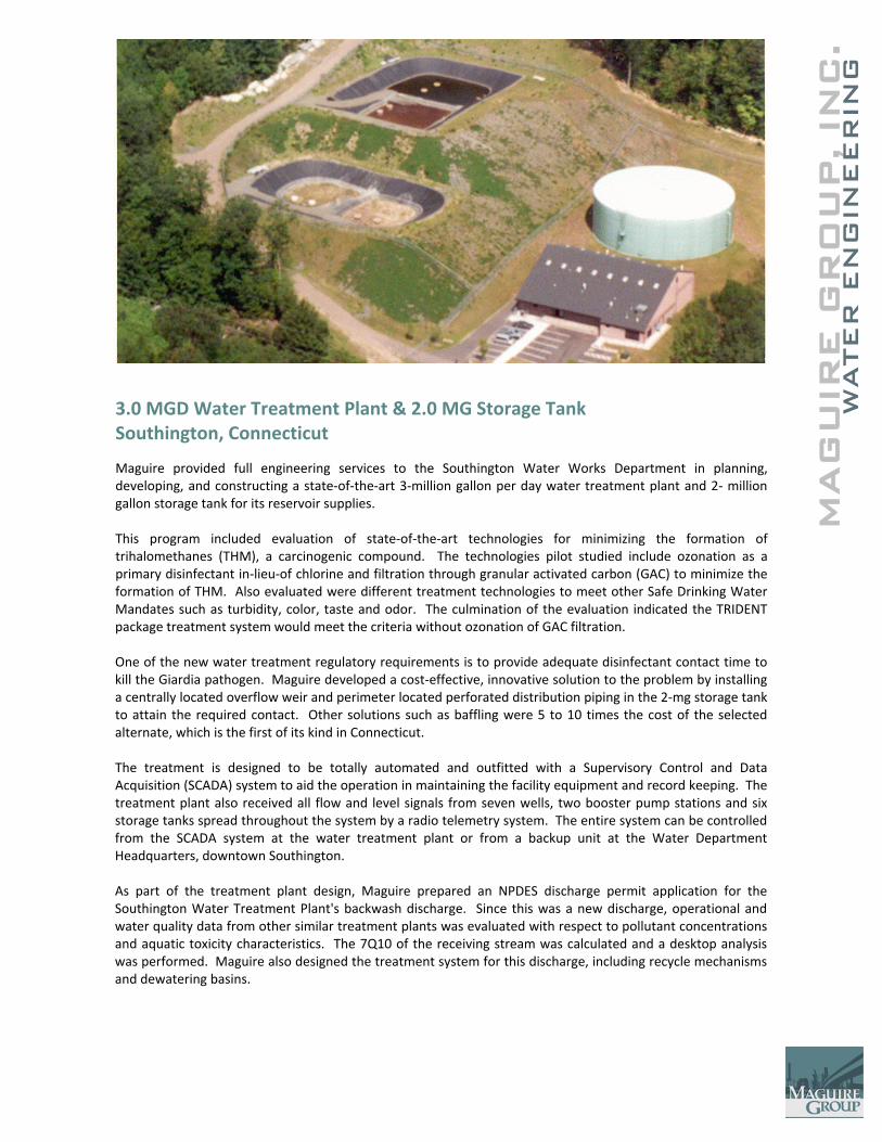
3.0 MGD Water Treatment Plant & 2.0 MG Storage Tank Southington, Connecticut
Maguire provided full engineering services to the Southington Water Works Department in planning, developing, and constructing a state‐of‐the‐art 3‐million gallon per day water treatment plant and 2‐ million gallon storage tank for its reservoir supplies. This program included evaluation of state‐of‐the‐art technologies for minimizing the formation of trihalomethanes (THM), a carcinogenic compound. The technologies pilot studied include ozonation as a primary disinfectant in‐lieu‐of chlorine and filtration through granular activated carbon (GAC) to minimize the formation of THM. Also evaluated were different treatment technologies to meet other Safe Drinking Water Mandates such as turbidity, color, taste and odor. The culmination of the evaluation indicated the TRIDENT package treatment system would meet the criteria without ozonation of GAC filtration. One of the new water treatment regulatory requirements is to provide adequate disinfectant contact time to kill the Giardia pathogen. Maguire developed a cost‐effective, innovative solution to the problem by installing a centrally located overflow weir and perimeter located perforated distribution piping in the 2‐mg storage tank to attain the required contact. Other solutions such as baffling were 5 to 10 times the cost of the selected alternate, which is the first of its kind in Connecticut. The treatment is designed to be totally automated and outfitted with a Supervisory Control and Data Acquisition (SCADA) system to aid the operation in maintaining the facility equipment and record keeping. The treatment plant also received all flow and level signals from seven wells, two booster pump stations and six storage tanks spread throughout the system by a radio telemetry system. The entire system can be controlled from the SCADA system at the water treatment plant or from a backup unit at the Water Department Headquarters, downtown Southington. As part of the treatment plant design, Maguire prepared an NPDES discharge permit application for the Southington Water Treatment Plant's backwash discharge. Since this was a new discharge, operational and water quality data from other similar treatment plants was evaluated with respect to pollutant concentrations and aquatic toxicity characteristics. The 7Q10 of the receiving stream was calculated and a desktop analysis was performed. Maguire also designed the treatment system for this discharge, including recycle mechanisms and dewatering basins.
C.
MAG
UIR
E G
RO
UP, IN
WATER
EN
GIN
EER
ING
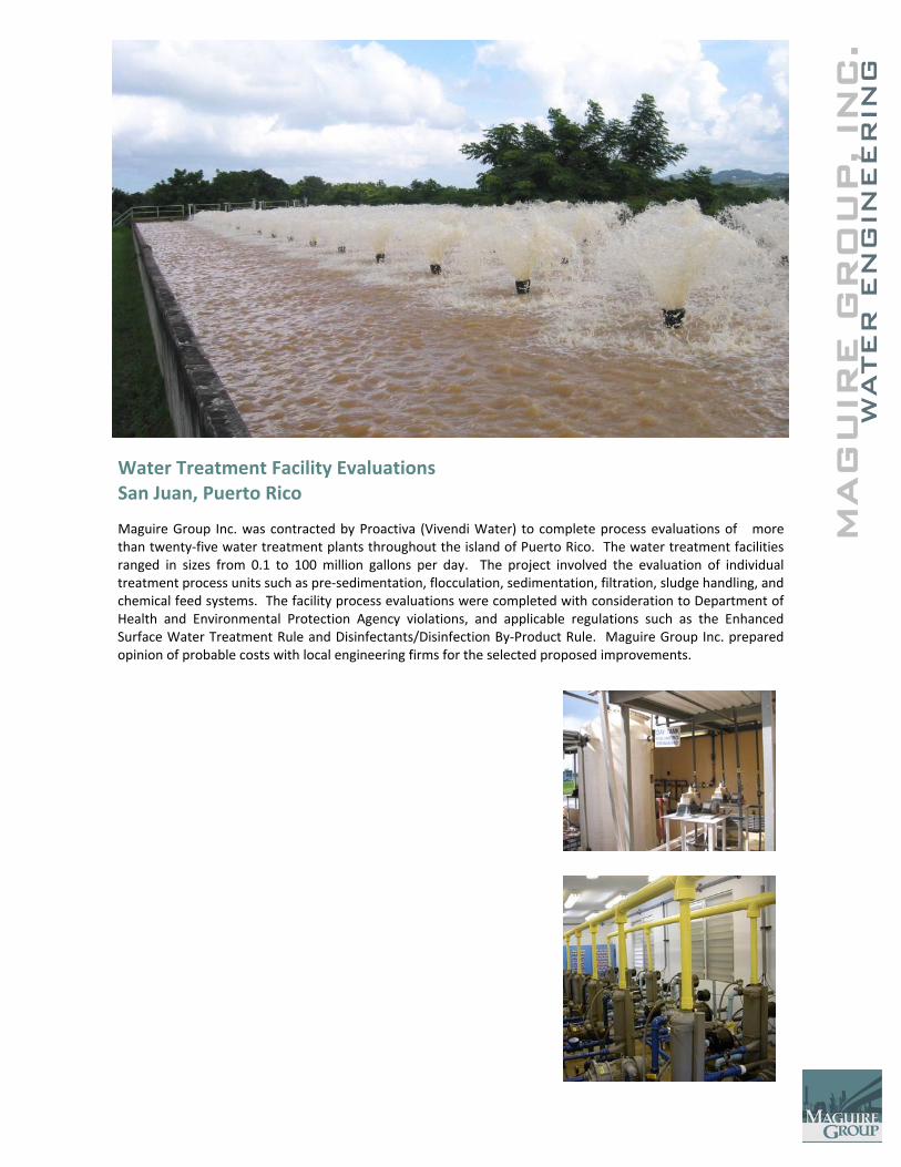
Water Treatment Facility Evaluations San Juan, Puerto Rico
Maguire Group Inc. was contracted by Proactiva (Vivendi Water) to complete process evaluations of more than twenty‐five water treatment plants throughout the island of Puerto Rico. The water treatment facilities ranged in sizes from 0.1 to 100 million gallons per day. The project involved the evaluation of individual treatment process units such as pre‐sedimentation, flocculation, sedimentation, filtration, sludge handling, and chemical feed systems. The facility process evaluations were completed with consideration to Department of Health and Environmental Protection Agency violations, and applicable regulations such as the Enhanced Surface Water Treatment Rule and Disinfectants/Disinfection By‐Product Rule. Maguire Group Inc. prepared opinion of probable costs with local engineering firms for the selected proposed improvements.
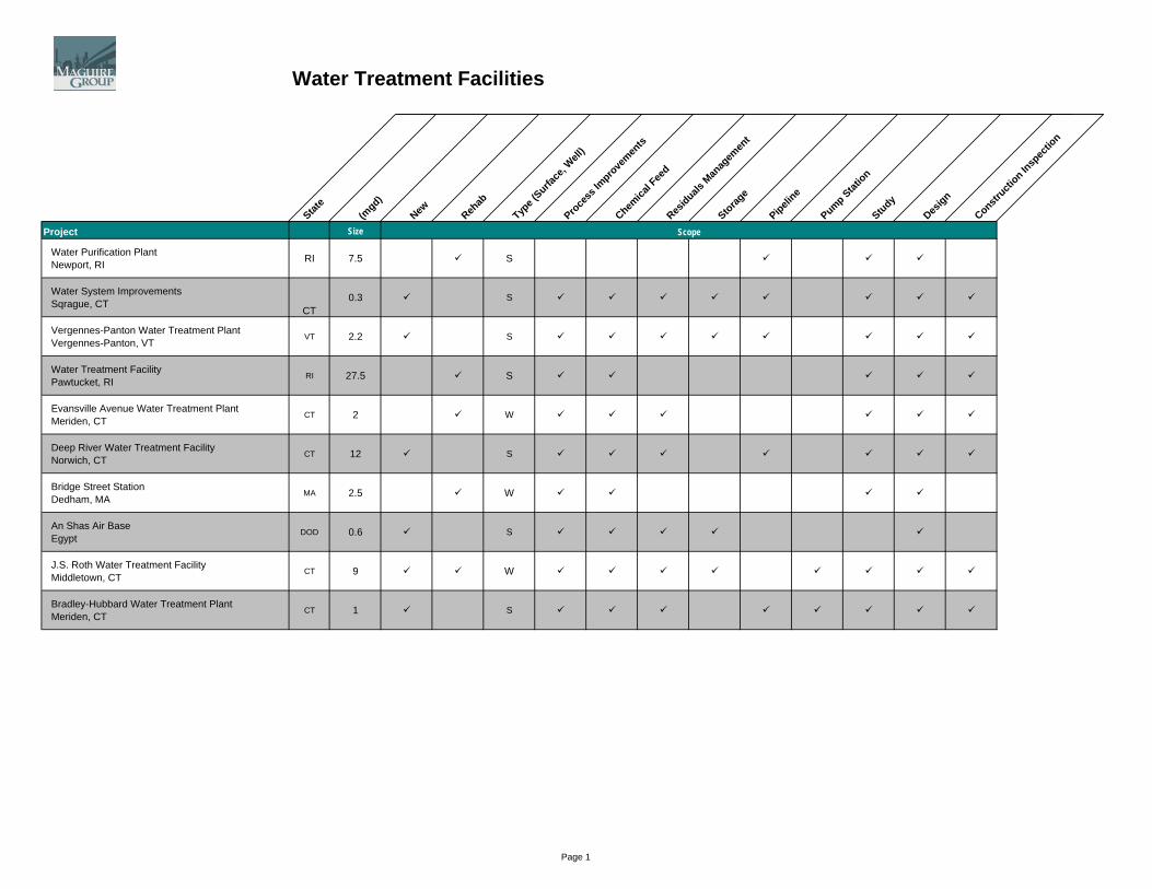
Water Treatment Facilities
State
(mgd)
New Rehab
Type (
Surface
, Well
)Pro
cess
Impro
vemen
ts
Chemica
l Fee
dRes
iduals M
anag
emen
t
Storage
Pipeline
Pump Station
Study
Design
Constructi
on Insp
ectio
n
ScopeProject Size
Water Purification PlantNewport, RI RI 7.5 S
Water System ImprovementsSqrague, CT
CT0.3 S
Vergennes-Panton Water Treatment PlantVergennes-Panton, VT
VT 2.2 S
Water Treatment FacilityPawtucket, RI
RI 27.5 S
Evansville Avenue Water Treatment PlantMeriden, CT
CT 2 W
Deep River Water Treatment FacilityNorwich, CT
CT 12 S
Bridge Street StationDedham, MA
MA 2.5 W
An Shas Air BaseEgypt
DOD 0.6 S
J.S. Roth Water Treatment FacilityMiddletown, CT
CT 9 W
Bradley-Hubbard Water Treatment PlantMeriden, CT
CT 1 S
Scope
Page 1
Water Treatment Facilities
State
(mgd)
New Rehab
Type (
Surface
, Well
)Pro
cess
Impro
vemen
ts
Chemica
l Fee
dRes
iduals M
anag
emen
t
Storage
Pipeline
Pump Station
Study
Design
Constructi
on Insp
ectio
n
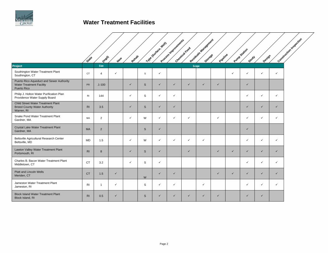
ScopeProject Size Scope
Southington Water Treatment PlantSouthington, CT
CT 4 S
Puerto Rico Aqueduct and Sewer Authority Water Treatment FacilityPuerto Rico
PR .1-100 S
Philip J. Holton Water Purification PlanProvidence Water Supply Board
RI 144 S
Child Street Water Treatment PlantBristol County Water AuthorityWarren, RI
RI 3.5 S
Snake Pond Water Treatment PlantGardner, MA
MA 2 W
Crystal Lake Water Treatment PlantGardner, MA MA 2 S
Beltsville Agricultural Research CenterBeltsville, MD MD 1.5 W
Lawton Valley Water Treatment PlantPortsmouth, RI RI 8 S
Charles B. Bacon Water Treatment PlantMiddletown, CT CT 3.2 S
Platt and Lincoln WellsMeriden, CT CT 1.5
W
Jameston Water Treatment PlantJameston, RI RI 1 S
Block Island Water Treatment PlantBlock Island, RI RI 0.5 S
Page 2
Water Systems Plan and Studies
State
Wells
Surface
StudyDam
sRes
ervoirs
Water Q
uality
Study
Rate Study
Treatm
ent F
acilit
y
Tank,
Elevate
dTan
k, Gro
undTunne
lsPump/B
ooster F
acilit
ies
Pipelines
Leak D
etecti
onMete
ring
Environm
ental
Ass
essm
ent
Aqueducts
Computer M
odeli
ng
Master
PlanRes
ource
Mgmt.
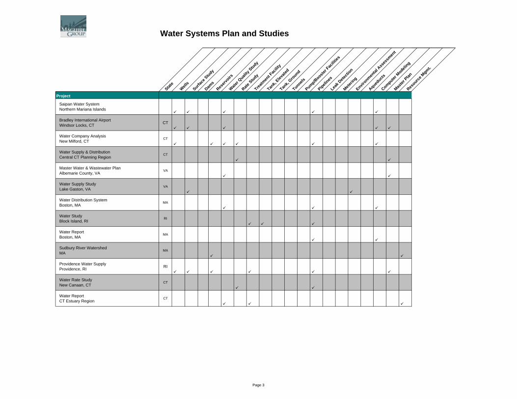
Project
Saipan Water SystemNorthern Mariana Islands
Bradley International AirportWindsor Locks, CT CT
Water Company AnalysisNew Milford, CT
CT
Water Supply & DistributionCentral CT Planning Region
CT
Master Water & Wastewater PlanAlbemarie County, VA
VA
Water Supply StudyLake Gaston, VA
VA
Water Distribution SystemBoston, MA
MA
Water StudyBlock Island, RI
RI
Water ReportBoston, MA
MA
Sudbury River WatershedMA
MA
Providence Water SupplyProvidence, RI RI
Water Rate StudyNew Canaan, CT
CT
Water ReportCT Estuary Region
CT
Page 3
Water Systems Plan and Studies
State
Wells
Surface
StudyDam
sRes
ervoirs
Water Q
uality
Study
Rate Study
Treatm
ent F
acilit
y
Tank,
Elevate
dTan
k, Gro
undTunne
lsPump/B
ooster F
acilit
ies
Pipelines
Leak D
etecti
onMete
ring
Environm
ental
Ass
essm
ent
Aqueducts
Computer M
odeli
ng
Master
PlanRes
ource
Mgmt.
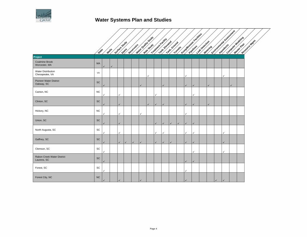
Project
Coalmine BrookWorcester, MA MA
Water DistributionChesapeake, VA
VA
Pioneer Water DistrictOakway, SC SC
Canton, NC NC
Clinton, SC SC
Hickory, NC NC
Union, SC SC
North Augusta, SC SC
Gaffney, SC SC
Clemson, SC SC
Rabon Creek Water DistrictLaurens, SC SC
Forest, SC SC
Forest City, NC NC
Page 4

Water Systems Plan and Studies
State
Wells
Surface
StudyDam
sRes
ervoirs
Water Q
uality
Study
Rate Study
Treatm
ent F
acilit
y
Tank,
Elevate
dTan
k, Gro
undTunne
lsPump/B
ooster F
acilit
ies
Pipelines
Leak D
etecti
onMete
ring
Environm
ental
Ass
essm
ent
Aqueducts
Computer M
odeli
ng
Master
PlanRes
ource
Mgmt.
Project
Water StudyMeriden, CT CT
Water StudyNY-NJ Port Authority NJ
USDABeltsville, MD MD
Water StudyMiddletown, CT CT
Water StudyNorwich, CT CT
Water StudyLeominster, MA MA
Water StudyGardner, MA MA
Water StudyEast Lym, CT CT
Water StudyAquidneck Island, RI RI
Water Rate Study (3 Phases)Rhode Island Water Resource Board RI
Page 5
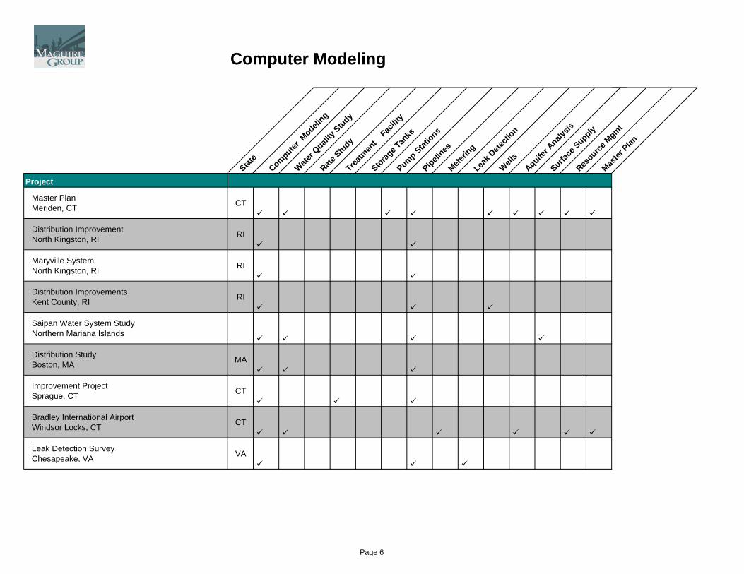
Computer Modeling
State
Computer M
odeling
Water Q
uality
Study
Rate Study
Treatm
ent
Facilit
y
Storage T
anks
Pump Stations
Pipelines
Meterin
gLea
k Dete
ction
Wells
Aquifer A
nalysis
Surface
SupplyRes
ource M
gmt
Master
Plan
Project
Master PlanMeriden, CT CT
Distribution ImprovementNorth Kingston, RI RI
Maryville SystemNorth Kingston, RI RI
Distribution ImprovementsKent County, RI RI
Saipan Water System StudyNorthern Mariana Islands
Distribution StudyBoston, MA MA
Improvement ProjectSprague, CT CT
Bradley International AirportWindsor Locks, CT CT
Leak Detection SurveyChesapeake, VA VA
Page 6
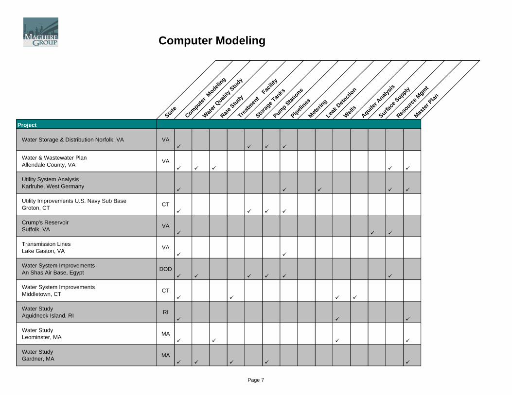
Computer Modeling
State
Computer M
odeling
Water Q
uality
Study
Rate Study
Treatm
ent
Facilit
y
Storage T
anks
Pump Stations
Pipelines
Meterin
gLea
k Dete
ction
Wells
Aquifer A
nalysis
Surface
SupplyRes
ource M
gmt
Master
Plan
Project
Water Storage & Distribution Norfolk, VA VA
Water & Wastewater PlanAllendale County, VA VA
Utility System AnalysisKarlruhe, West Germany
Utility Improvements U.S. Navy Sub BaseGroton, CT CT
Crump's ReservoirSuffolk, VA VA
Transmission LinesLake Gaston, VA VA
Water System ImprovementsAn Shas Air Base, Egypt DOD
Water System ImprovementsMiddletown, CT CT Water StudyAquidneck Island, RI RI
Water StudyLeominster, MA MA
Water StudyGardner, MA MA
Page 7
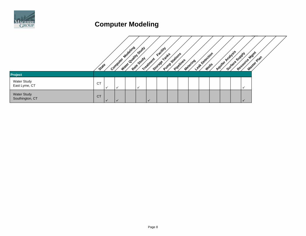
Computer Modeling
State
Computer M
odeling
Water Q
uality
Study
Rate Study
Treatm
ent
Facilit
y
Storage T
anks
Pump Stations
Pipelines
Meterin
gLea
k Dete
ction
Wells
Aquifer A
nalysis
Surface
SupplyRes
ource M
gmt
Master
Plan
Project
Water StudyEast Lyme, CT CT
Water StudySouthington, CT CT
Page 8
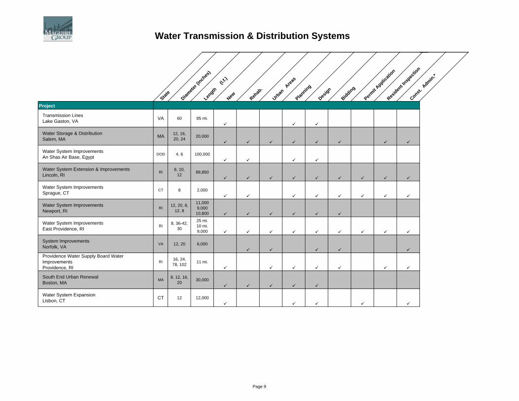
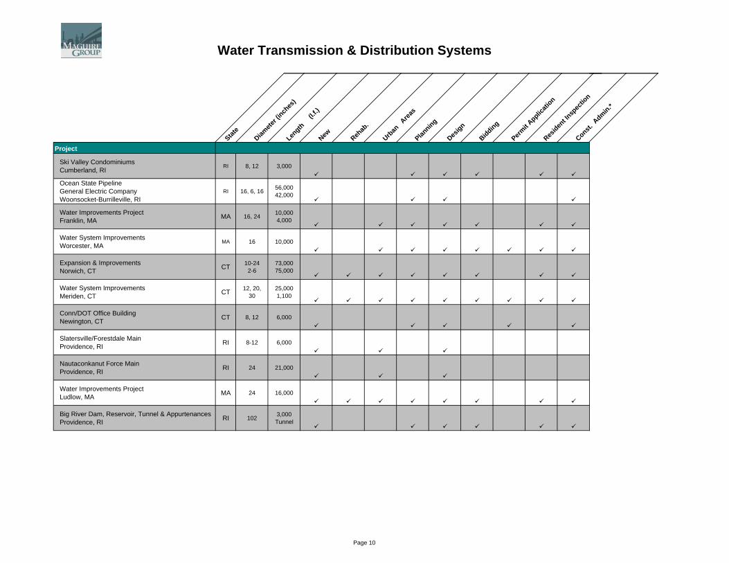
Water Transmission & Distribution Systems
State
Diamete
r (inch
es)
Length
(l.f.)
New Rehab
.
Urban
Area
sPlan
ning
Design
Bidding
Permit A
pplicati
onRes
ident In
spec
tion
Const. A
dmin.*
Project
Transmission LinesLake Gaston, VA VA 60 85 mi.
Water Storage & DistributionSalem, MA MA 12, 16,
20, 24 20,000
Water System ImprovementsAn Shas Air Base, Egypt
DOD 4, 6 100,000
Water System Extension & ImprovementsLincoln, RI
RI 8, 10, 12 89,850
Water System ImprovementsSprague, CT
CT 8 2,000
Water System ImprovementsNewport, RI
RI 12, 20, 8, 12, 8
11,000 9,000 10,800
Water System ImprovementsEast Providence, RI
RI 8, 36-42, 30
25 mi. 10 mi. 9,000
System ImprovementsNorfolk, VA
VA 12, 20 6,000
Providence Water Supply Board Water ImprovementsProvidence, RI
RI 16, 24, 78, 102 11 mi.
South End Urban RenewalBoston, MA
MA 8, 12, 16, 20 30,000
Water System ExpansionLisbon, CT CT 12 12,000
Page 9
Water Transmission & Distribution Systems
State
Diamete
r (inch
es)
Length
(l.f.)
New Rehab
.
Urban
Area
sPlan
ning
Design
Bidding
Permit A
pplicati
onRes
ident In
spec
tion
Const. A
dmin.*
Project
Ski Valley CondominiumsCumberland, RI
RI 8, 12 3,000
Ocean State PipelineGeneral Electric CompanyWoonsocket-Burrilleville, RI
RI 16, 6, 16 56,000 42,000
Water Improvements ProjectFranklin, MA MA 16, 24 10,000
4,000
Water System ImprovementsWorcester, MA
MA 16 10,000
Expansion & ImprovementsNorwich, CT CT 10-24
2-673,000 75,000
Water System ImprovementsMeriden, CT CT 12, 20,
3025,000 1,100
Conn/DOT Office BuildingNewington, CT CT 8, 12 6,000
Slatersville/Forestdale MainProvidence, RI RI 8-12 6,000
Nautaconkanut Force MainProvidence, RI RI 24 21,000
Water Improvements ProjectLudlow, MA MA 24 16,000
Big River Dam, Reservoir, Tunnel & AppurtenancesProvidence, RI RI 102 3,000
Tunnel
Page 10

Water Transmission & Distribution Systems
State
Diamete
r (inch
es)
Length
(l.f.)
New Rehab
.
Urban
Area
sPlan
ning
Design
Bidding
Permit A
pplicati
onRes
ident In
spec
tion
Const. A
dmin.*
Project
Utility ImprovementsU.S. Sub Base, Groton, CT CT 12 7,000
Water Distribution ImprovementsNorth Attleboro, MA MA 12 5,000
Water Improvements Projects Phases I & IIPawtucket, RI RI 12, 20
2648,190 20,760
Water System Improvements Bradley International AirportWindsor Locks, CT
CT 16 10,000
Wayne Township Water MainsWayne, NJ NJ 16, 12 1,700
30
Water Main ReplacementPort Authority of New York & New Jersey NJ 16 4,000
Route 86 Relocation of Water Transmissions MainNew London, CT CT 30 1,600
Water System ImprovementsSouthington, CT CT 12, 8, 10-
12
15,700 3,800 15,300
Downtown RedevelopmentMeriden, CT CT 8-10, 12,
16 6,600
Church Street MarketplaceBurlington, CT CT 16 2,200
Page 11
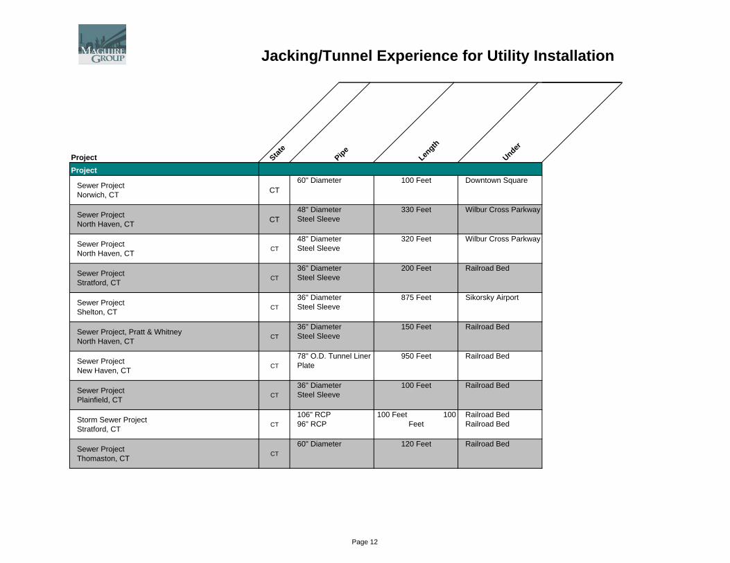
Jacking/Tunnel Experience for Utility Installation
Project State
Pipe
Length
Under
Project
Sewer ProjectNorwich, CT CT
60" Diameter 100 Feet Downtown Square
Sewer ProjectNorth Haven, CT CT
48" Diameter Steel Sleeve
330 Feet Wilbur Cross Parkway
Sewer ProjectNorth Haven, CT
CT48" Diameter Steel Sleeve
320 Feet Wilbur Cross Parkway
Sewer ProjectStratford, CT
CT36" Diameter Steel Sleeve
200 Feet Railroad Bed
Sewer ProjectShelton, CT
CT36" Diameter Steel Sleeve
875 Feet Sikorsky Airport
Sewer Project, Pratt & WhitneyNorth Haven, CT
CT36" Diameter Steel Sleeve
150 Feet Railroad Bed
Sewer ProjectNew Haven, CT
CT78" O.D. Tunnel Liner Plate
950 Feet Railroad Bed
Sewer ProjectPlainfield, CT
CT36" Diameter Steel Sleeve
100 Feet Railroad Bed
Storm Sewer ProjectStratford, CT
CT106" RCP 96" RCP
100 Feet 100 Feet
Railroad Bed Railroad Bed
Sewer ProjectThomaston, CT
CT60" Diameter 120 Feet Railroad Bed
Page 12
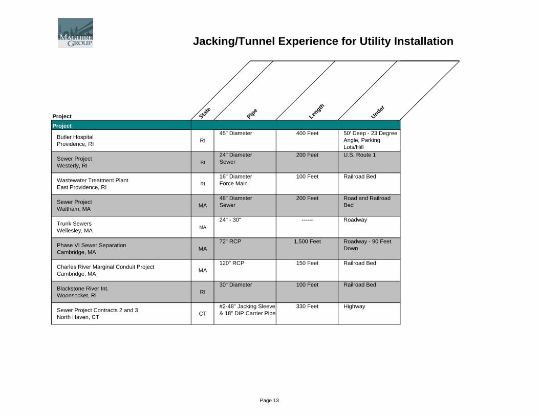
Jacking/Tunnel Experience for Utility Installation
Project State
Pipe
Length
Under
Project
Butler HospitalProvidence, RI RI
45" Diameter 400 Feet 50' Deep - 23 Degree Angle, Parking Lots/Hill
Sewer ProjectWesterly, RI
RI24" Diameter Sewer
200 Feet U.S. Route 1
Wastewater Treatment PlantEast Providence, RI
RI16" Diameter Force Main
100 Feet Railroad Bed
Sewer ProjectWaltham, MA MA
48" Diameter Sewer
200 Feet Road and Railroad Bed
Trunk SewersWellesley, MA
MA24" - 30" ------ Roadway
Phase VI Sewer SeparationCambridge, MA MA
72" RCP 1,500 Feet Roadway - 90 Feet Down
Charles River Marginal Conduit ProjectCambridge, MA MA
120" RCP 150 Feet Railroad Bed
Blackstone River Int.Woonsocket, RI RI
30" Diameter 100 Feet Railroad Bed
Sewer Project Contracts 2 and 3North Haven, CT CT
#2-48" Jacking Sleeve & 18" DIP Carrier Pipe
330 Feet Highway
Page 13


MAG
UIR
E G
RO
UP, IN
TAB
LE O
F C
ON
TEN
TS
C
.
Section I Company Overview Section II Water Engineering Section III Wastewater Engineering Section IV Dam Engineering

MAG
UIR
E G
RO
UP, IN
WAS
TEW
ATER
EN
GIN
EER
ING
C
.
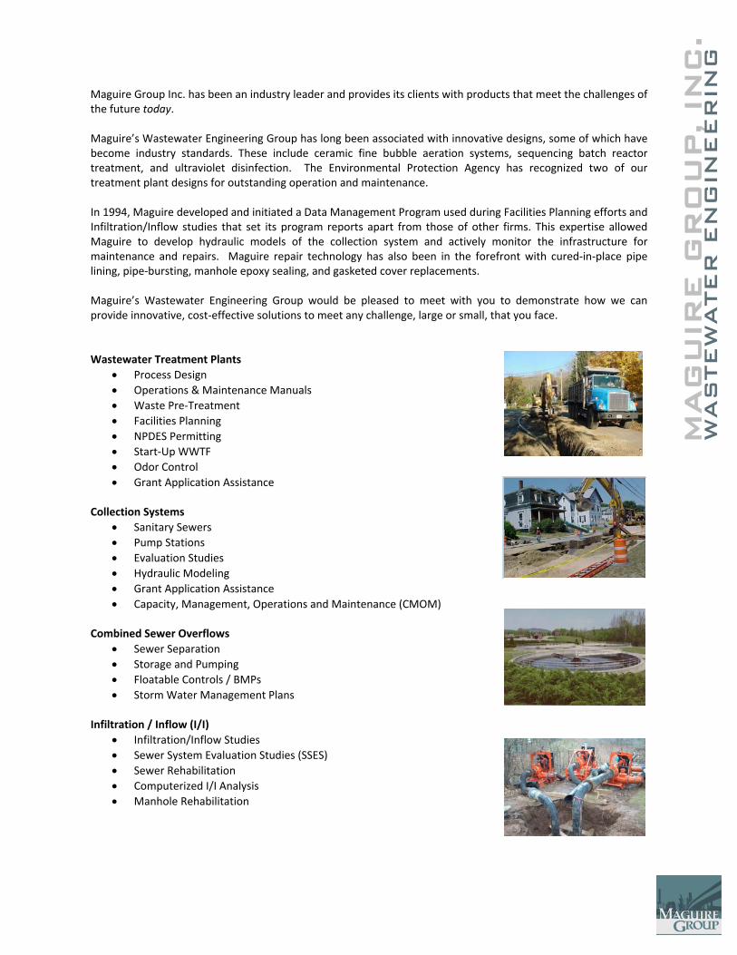
Maguire Group Inc. has been an industry leader and provides its clients with products that meet the challenges of the future today. Maguire’s Wastewater Engineering Group has long been associated with innovative designs, some of which have become industry standards. These include ceramic fine bubble aeration systems, sequencing batch reactor treatment, and ultraviolet disinfection. The Environmental Protection Agency has recognized two of our treatment plant designs for outstanding operation and maintenance. In 1994, Maguire developed and initiated a Data Management Program used during Facilities Planning efforts and Infiltration/Inflow studies that set its program reports apart from those of other firms. This expertise allowed Maguire to develop hydraulic models of the collection system and actively monitor the infrastructure for maintenance and repairs. Maguire repair technology has also been in the forefront with cured‐in‐place pipe lining, pipe‐bursting, manhole epoxy sealing, and gasketed cover replacements. Maguire’s Wastewater Engineering Group would be pleased to meet with you to demonstrate how we can provide innovative, cost‐effective solutions to meet any challenge, large or small, that you face. Wastewater Treatment Plants
• Process Design • Operations & Maintenance Manuals • Waste Pre‐Treatment • Facilities Planning • NPDES Permitting • Start‐Up WWTF • Odor Control • Grant Application Assistance
Collection Systems
• Sanitary Sewers • Pump Stations • Evaluation Studies • Hydraulic Modeling • Grant Application Assistance • Capacity, Management, Operations and Maintenance (CMOM)
Combined Sewer Overflows
• Sewer Separation • Storage and Pumping • Floatable Controls / BMPs • Storm Water Management Plans
Infiltration / Inflow (I/I)
• Infiltration/Inflow Studies • Sewer System Evaluation Studies (SSES) • Sewer Rehabilitation • Computerized I/I Analysis • Manhole Rehabilitation

C.
MAG
UIR
E G
RO
UP, IN
WAS
TEW
ATER
EN
GIN
EER
ING
Pump Station #200 Construction Management Services Hialeah, Florida Cost: $5,600,000 Year Completion: 2009
The Hialeah Pump Station # 200 is a 9.9 MGD wastewater pumping station that was constructed by the City of Hialeah Water & Sewers Department. The project included the construction of a wetwell, pump chamber and building using innovative dewatering and sheeting techniques. Dry pit pump chamber included (4) 450 HP dry‐pit submersible pumps. Maguire provided construction contract administration and resident inspection services through project startup. Project Features
• Document Control via Primavera Contract Manager
• Construction Administration
• Full‐Time Resident Inspection
• Claims Evaluation
• Schedule Monitoring
• Shop Drawing Submission & Distribution
• Daily Reports
• RFI’s
• Construction Photos
• Progress Meetings
C.
MAG
UIR
E G
RO
UP, IN
WAS
TEW
ATER
EN
GIN
EER
ING
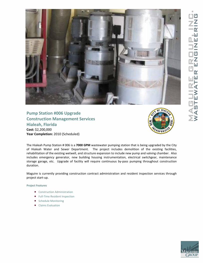
Pump Station #006 Upgrade Construction Management Services Hialeah, Florida Cost: $2,200,000 Year Completion: 2010 (Scheduled)
The Hialeah Pump Station # 006 is a 7000 GPM wastewater pumping station that is being upgraded by the City of Hialeah Water and Sewer Department. The project includes demolition of the existing facilities, rehabilitation of the existing wetwell, and structure expansion to include new pump and valving chamber. Also includes emergency generator, new building housing instrumentation, electrical switchgear, maintenance storage garage, etc. Upgrade of facility will require continuous by‐pass pumping throughout construction duration. Maguire is currently providing construction contract administration and resident inspection services through project start‐up. Project Features
• Construction Administration
• Full‐Time Resident Inspection
• Schedule Monitoring
• Claims Evaluation

C.
MAG
UIR
E G
RO
UP, IN
WAS
TEW
ATER
EN
GIN
EER
ING
Naamans Creek Wastewater Pump Station and Force Main Marcus Hook, Pennsylvania Maguire Group Inc. was engaged by Catania Engineering Associates of Milmont, PA to redesign the Naamans Creek wastewater pumping station (NCPS) and force main for the Southern Delaware County Authority (SDCA). Prior to Maguire Group’s involvement, Catania Engineering Associates had already designed the project with a firm capacity of 3‐mgd (million gallons per day) and the SDCA had already bid and awarded five construction contracts based on that capacity. The redesign was necessary because the SDCA subsequently determined the need to increase the capacity of the station and force main from 3‐mgd to 8‐mgd. Because SDCA had already awarded the construction contracts for this work, Maguire Group was tasked with the speedy redesign of the station and force main and the timely issuance of several Change Order Request Bulletins for each of the five contractors. Change Order Request Bulletins were prepared and issued in priority of the most urgent station components for the purpose of avoiding costly delays in constructing the project. The redesigned pumping station is a custom‐designed, built‐in‐place facility with three non‐clog vertical‐centrifugal solids‐handling pumps with extended power shafting. The adjustable speed of the 200‐horsepower, premium‐efficiency pump drive motors is controlled by variable frequency controllers based on influent wetwell level. Each pump has a capacity range of approximately 400 gpm to over 4000 gpm. The redesigned pumping station has a firm capacity, with one pump in standby, of 5560 gpm (8 mgd). The emergency power system comprises a 400‐kW diesel generator with a 1200 Ampere automatic transfer switch. The NCPS discharges through a new 20‐inch diameter ductile iron force main to an existing 36‐inch diameter force main from the Sunoco oil refinery to the DELCORA wastewater treatment plant. The NCPS pump selection, force main hydraulics, and pumping system control strategy were unusually complex because of the wide range of flows anticipated in the combined DELCORA force main. These problems were solved successfully by computer simulation of the various discharge scenarios and design of an automatic pump control system that continuously monitors the force main discharge pressure and maintains the pump speeds within an acceptable operating range. The Southern Delaware County Authority, located in southeastern Pennsylvania, has historically discharged its collected wastewater through a gravity interceptor sewer into the State of Delaware. The Namaans Creek Pumping Station and Force Main Project now allow the SDCA to send its wastewater flows to a much more cost‐effective treatment and disposal facility (DELCORA) within the Commonwealth of Pennsylvania.

C.
MAG
UIR
E G
RO
UP, IN
WAS
TEW
ATER
EN
GIN
EER
ING
Electric Avenue, Kennedy Drive, Hickory Hill Road, and Woodbridge Lane Pump Stations Thomaston, Connecticut This project involved the rehabilitation design of four (4) wastewater pumping stations, ranging in capacity from 50 gpm to 350 gpm. One of the stations is a submersible pump type station while the other three are wet pit/dry pit type stations with vertical centrifugal pumps. The scope of work of rehabilitation included new replacement wastewater pumps, hydraulic actuated control valves, emergency generators housed in new precast concrete buildings, removal of buried fuel oil storage tanks and replacement with above‐grade fuel‐oil storage tanks in double‐containment vaults, an odor control system, and site improvements including grading, paving and fencing. The construction scope of work for the rehabilitation work included sequencing of the construction activities to ensure that all pump stations remain on‐line during virtually all of the rehabilitation work. Wastewater pump models were standardized to reduce the Town’s spare parts inventory and personnel training. Maguire also provided Contract Administration and Resident Inspection for this project.
C.
MAG
UIR
E G
RO
UP, IN
WAS
TEW
ATER
EN
GIN
EER
ING
Gardner WWTF Phosphorus and Copper Treatment Studies Gardner, Massachusetts Mr. Dane Arnold ‐ DPW Director 978‐632‐7661 Year of Completion: Ongoing Maguire Group is providing engineering services to assist the Gardner Department of Public Works in evaluating phosphorus and copper treatability at the Gardner Wastewater Treatment Facility. In 2004, the Gardner WWTF received a revised discharge permit that lowered the monthly average total phosphorus effluent limit from 0.9 to 0.2 milligrams per liter (mg/L) and notified the City that its interim copper limit of 66 micrograms per liter (ug/L) would be lowered to 15 ug/L. During 2005‐2006, Maguire completed a full‐scale pilot treatability study at the WWTF to evaluate the effectiveness of chemical salt (ferric/alum) precipitation to remove phosphorus and copper to meet the facility’s effluent discharge limits. Based on the process optimization study and treatability study performed by Maguire, the following opportunities for copper and phosphorus reduction were offered:
• Perform water system corrosion control evaluations; considering the impact of phosphate‐containing corrosion inhibitors on WWTF phosphorus loadings.
• Perform a WWTF phosphorus‐loading evaluation and phosphorus and copper reduction program using metal salts or other coagulants for chemical precipitation.
• Conduct a site‐specific evaluation for copper bioavailability/toxicity and request adjusted NPDES permit limits accordingly.
The Gardner WWTF was able to successfully meet its 2004 NPDES permit for phosphorus, averaging 0.15 mg/l between 2004 and 2008. In 2009, the City’s was notified that its NPDES discharge permit would include a further reduction in the effluent phosphorus limit to 0.1 mg/l. Maguire completed a Flows and Loads Analysis report that evaluated the plant’s ability to meet this new limit. The study concluded that the plant would require additional tertiary treatment to meet the new limit. Maguire is currently evaluating various treatment processes such as ballasted flocculation, DAF, along with other process modifications including sidestream treatment options to finalize the recommendation for the plant improvements.
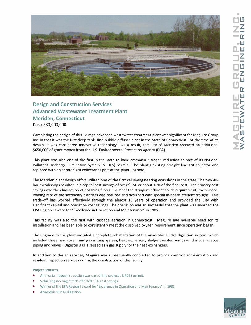
C.
MAG
UIR
E G
RO
UP, IN
WAS
TEW
ATER
EN
GIN
EER
ING
Design and Construction Services Advanced Wastewater Treatment Plant Meriden, Connecticut Cost: $30,000,000 Completing the design of this 12‐mgd advanced wastewater treatment plant was significant for Maguire Group Inc. in that it was the first deep‐tank, fine‐bubble diffuser plant in the State of Connecticut. At the time of its design, it was considered innovative technology. As a result, the City of Meriden received an additional $650,000 of grant money from the U.S. Environmental Protection Agency (EPA). This plant was also one of the first in the state to have ammonia nitrogen reduction as part of its National Pollutant Discharge Elimination System (NPDES) permit. The plant’s existing straight‐line grit collector was replaced with an aerated grit collector as part of the plant upgrade. The Meriden plant design effort utilized one of the first value‐engineering workshops in the state. The two 40‐hour workshops resulted in a capital cost savings of over $3M, or about 10% of the final cost. The primary cost savings was the elimination of polishing filters. To meet the stringent effluent solids requirement, the surface‐loading rate of the secondary clarifiers was reduced and designed with special in‐board effluent troughs. This trade‐off has worked effectively through the almost 15 years of operation and provided the City with significant capital and operation cost savings. The operation was so successful that the plant was awarded the EPA Region I award for “Excellence in Operation and Maintenance” in 1985. This facility was also the first with cascade aeration in Connecticut. Maguire had available head for its installation and has been able to consistently meet the dissolved oxygen requirement since operation began. The upgrade to the plant included a complete rehabilitation of the anaerobic sludge digestion system, which included three new covers and gas mixing system, heat exchanger, sludge transfer pumps an d miscellaneous piping and valves. Digester gas is reused as a gas supply for the heat exchangers. In addition to design services, Maguire was subsequently contracted to provide contract administration and resident inspection services during the construction of this facility. Project Features
• Ammonia nitrogen reduction was part of the project’s NPDES permit.
• Value‐engineering efforts effected 10% cost savings.
• Winner of the EPA Region I award for “Excellence in Operation and Maintenance” in 1985.
• Anaerobic sludge digestion
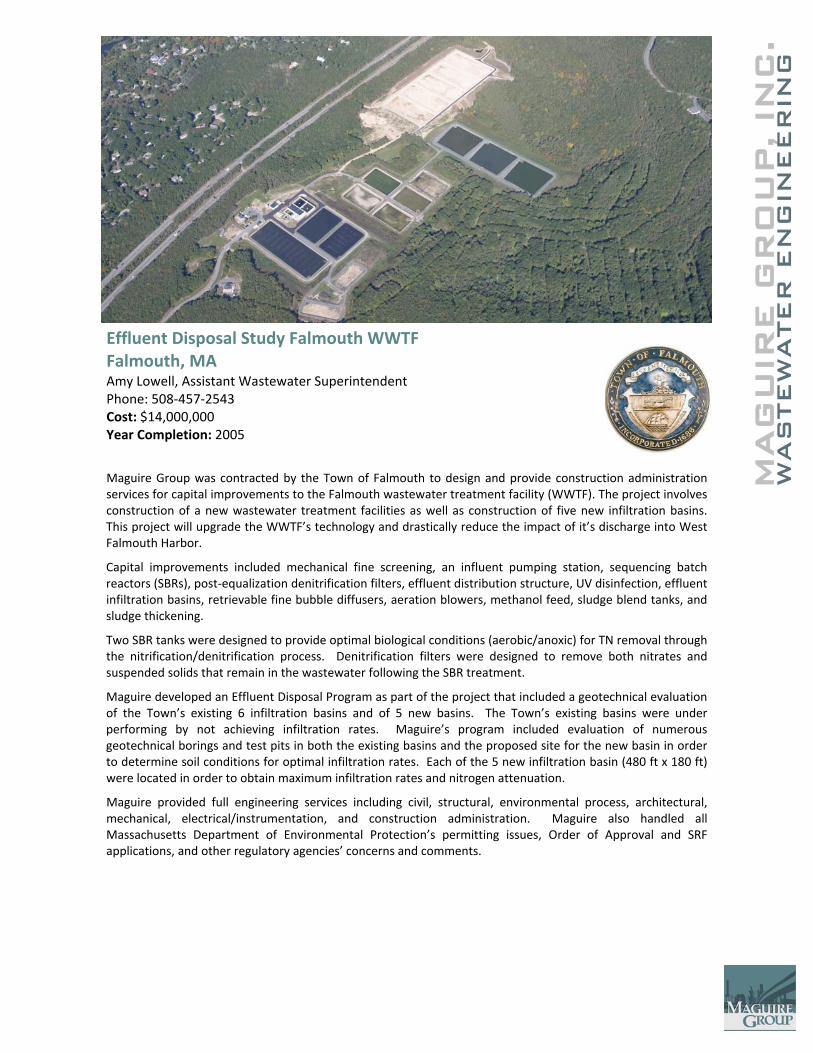
C.
MAG
UIR
E G
RO
UP, IN
WAS
TEW
ATER
EN
GIN
EER
ING
Effluent Disposal Study Falmouth WWTF Falmouth, MA Amy Lowell, Assistant Wastewater Superintendent Phone: 508‐457‐2543 Cost: $14,000,000 Year Completion: 2005 Maguire Group was contracted by the Town of Falmouth to design and provide construction administration services for capital improvements to the Falmouth wastewater treatment facility (WWTF). The project involves construction of a new wastewater treatment facilities as well as construction of five new infiltration basins. This project will upgrade the WWTF’s technology and drastically reduce the impact of it’s discharge into West Falmouth Harbor.
Capital improvements included mechanical fine screening, an influent pumping station, sequencing batch reactors (SBRs), post‐equalization denitrification filters, effluent distribution structure, UV disinfection, effluent infiltration basins, retrievable fine bubble diffusers, aeration blowers, methanol feed, sludge blend tanks, and sludge thickening.
Two SBR tanks were designed to provide optimal biological conditions (aerobic/anoxic) for TN removal through the nitrification/denitrification process. Denitrification filters were designed to remove both nitrates and suspended solids that remain in the wastewater following the SBR treatment.
Maguire developed an Effluent Disposal Program as part of the project that included a geotechnical evaluation of the Town’s existing 6 infiltration basins and of 5 new basins. The Town’s existing basins were under performing by not achieving infiltration rates. Maguire’s program included evaluation of numerous geotechnical borings and test pits in both the existing basins and the proposed site for the new basin in order to determine soil conditions for optimal infiltration rates. Each of the 5 new infiltration basin (480 ft x 180 ft) were located in order to obtain maximum infiltration rates and nitrogen attenuation.
Maguire provided full engineering services including civil, structural, environmental process, architectural, mechanical, electrical/instrumentation, and construction administration. Maguire also handled all Massachusetts Department of Environmental Protection’s permitting issues, Order of Approval and SRF applications, and other regulatory agencies’ concerns and comments.

C.
MAG
UIR
E G
RO
UP, IN
WAS
TEW
ATER
EN
GIN
EER
ING
Wastewater Treatment Plants St. Croix and St. Thomas, U.S.V.I. Government of the Virgin Islands Charles Bornman ‐ Senior Construction Manager 340/776‐4844 x 245 Cost: $26,000,000 Year Completion: 2007
The Government of the U.S. Virgin Islands (GVI) awarded its first‐ever design‐build‐operate contract to Veolia Water for the development of a long‐term solution to its wastewater management needs on the islands of St. Thomas and St. Croix. Maguire Group is part of the Veolia team for this comprehensive project: $123M, 20‐year contract to design, construct and operate upgrades and expansions for two new 4‐mgd wastewater treatment facilities (WWTF) located in Anguilla on St. Croix and at Red Point on St. Thomas. The project includes the decommissioning of certain existing treatment processes and providing new sequencing batch reactor (SBR) treatment facilities. These new facilities will help the territory meet the requirements of a Consent Agreement with the EPA concerning ocean discharge. The treatment plants will be capable of nitrogen reduction, and the St Croix plant will have the opportunity for water reuse. A number of alternative biological treatment processes was evaluated and the SBR technology was the option that provided the lowest present worth cost. Each of the plants will utilize SBR as the biological process for achieving the water quality goals of the Virgin Islands. Each plant will also utilize aerobic digestion to reduce the volume of sludge that must be disposed. The digestion process will reduce the volume of volatile solids by 40 percent and enables a significant reduction in operation cost.
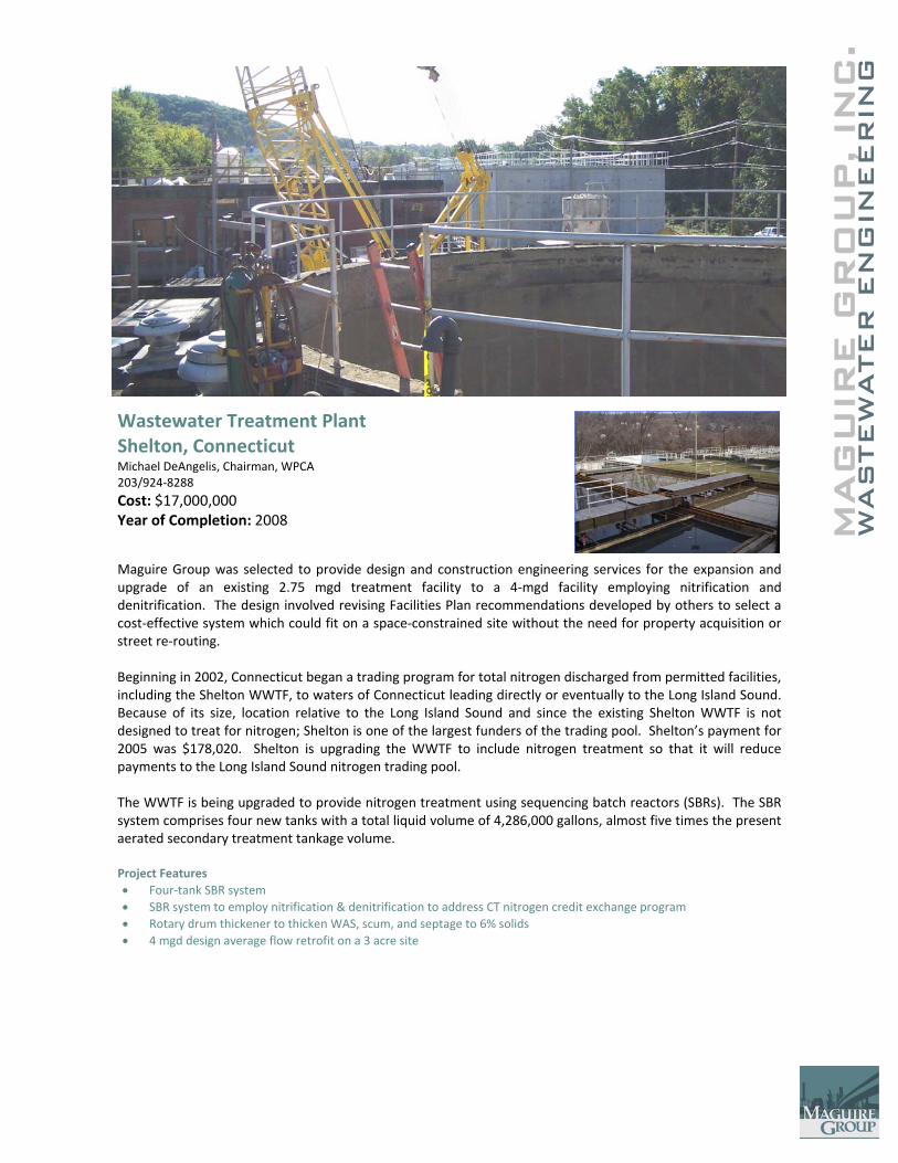
C.
MAG
UIR
E G
RO
UP, IN
WAS
TEW
ATER
EN
GIN
EER
ING
Wastewater Treatment Plant Shelton, Connecticut Michael DeAngelis, Chairman, WPCA 203/924‐8288 Cost: $17,000,000 Year of Completion: 2008
Maguire Group was selected to provide design and construction engineering services for the expansion and upgrade of an existing 2.75 mgd treatment facility to a 4‐mgd facility employing nitrification and denitrification. The design involved revising Facilities Plan recommendations developed by others to select a cost‐effective system which could fit on a space‐constrained site without the need for property acquisition or street re‐routing. Beginning in 2002, Connecticut began a trading program for total nitrogen discharged from permitted facilities, including the Shelton WWTF, to waters of Connecticut leading directly or eventually to the Long Island Sound. Because of its size, location relative to the Long Island Sound and since the existing Shelton WWTF is not designed to treat for nitrogen; Shelton is one of the largest funders of the trading pool. Shelton’s payment for 2005 was $178,020. Shelton is upgrading the WWTF to include nitrogen treatment so that it will reduce payments to the Long Island Sound nitrogen trading pool. The WWTF is being upgraded to provide nitrogen treatment using sequencing batch reactors (SBRs). The SBR system comprises four new tanks with a total liquid volume of 4,286,000 gallons, almost five times the present aerated secondary treatment tankage volume. Project Features • Four‐tank SBR system • SBR system to employ nitrification & denitrification to address CT nitrogen credit exchange program • Rotary drum thickener to thicken WAS, scum, and septage to 6% solids • 4 mgd design average flow retrofit on a 3 acre site
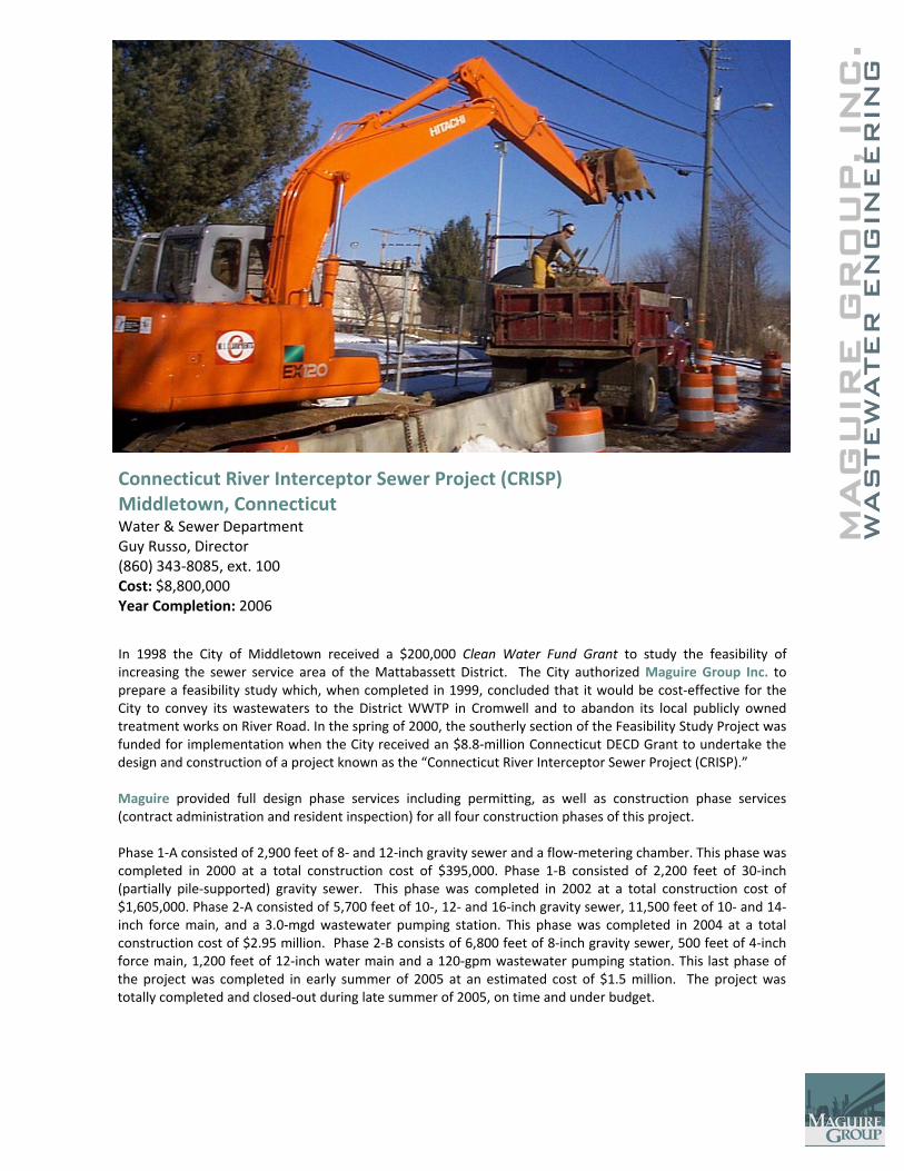
C.
MAG
UIR
E G
RO
UP, IN
WAS
TEW
ATER
EN
GIN
EER
ING
Connecticut River Interceptor Sewer Project (CRISP) Middletown, Connecticut Water & Sewer Department Guy Russo, Director (860) 343‐8085, ext. 100 Cost: $8,800,000 Year Completion: 2006 In 1998 the City of Middletown received a $200,000 Clean Water Fund Grant to study the feasibility of increasing the sewer service area of the Mattabassett District. The City authorized Maguire Group Inc. to prepare a feasibility study which, when completed in 1999, concluded that it would be cost‐effective for the City to convey its wastewaters to the District WWTP in Cromwell and to abandon its local publicly owned treatment works on River Road. In the spring of 2000, the southerly section of the Feasibility Study Project was funded for implementation when the City received an $8.8‐million Connecticut DECD Grant to undertake the design and construction of a project known as the “Connecticut River Interceptor Sewer Project (CRISP).” Maguire provided full design phase services including permitting, as well as construction phase services (contract administration and resident inspection) for all four construction phases of this project. Phase 1‐A consisted of 2,900 feet of 8‐ and 12‐inch gravity sewer and a flow‐metering chamber. This phase was completed in 2000 at a total construction cost of $395,000. Phase 1‐B consisted of 2,200 feet of 30‐inch (partially pile‐supported) gravity sewer. This phase was completed in 2002 at a total construction cost of $1,605,000. Phase 2‐A consisted of 5,700 feet of 10‐, 12‐ and 16‐inch gravity sewer, 11,500 feet of 10‐ and 14‐inch force main, and a 3.0‐mgd wastewater pumping station. This phase was completed in 2004 at a total construction cost of $2.95 million. Phase 2‐B consists of 6,800 feet of 8‐inch gravity sewer, 500 feet of 4‐inch force main, 1,200 feet of 12‐inch water main and a 120‐gpm wastewater pumping station. This last phase of the project was completed in early summer of 2005 at an estimated cost of $1.5 million. The project was totally completed and closed‐out during late summer of 2005, on time and under budget.
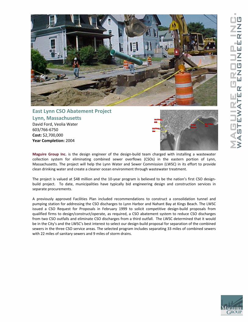
C.
MAG
UIR
E G
RO
UP, IN
WAS
TEW
ATER
EN
GIN
EER
ING
East Lynn CSO Abatement Project Lynn, Massachusetts David Ford, Veolia Water 603/766‐6750 Cost: $2,700,000 Year Completion: 2004
Maguire Group Inc. is the design engineer of the design‐build team charged with installing a wastewater collection system for eliminating combined sewer overflows (CSOs) in the eastern portion of Lynn, Massachusetts. The project will help the Lynn Water and Sewer Commission (LWSC) in its effort to provide clean drinking water and create a cleaner ocean environment through wastewater treatment. The project is valued at $48 million and the 10‐year program is believed to be the nation’s first CSO design‐build project. To date, municipalities have typically bid engineering design and construction services in separate procurements. A previously approved Facilities Plan included recommendations to construct a consolidation tunnel and pumping station for addressing the CSO discharges to Lynn Harbor and Nahant Bay at Kings Beach. The LWSC issued a CSO Request for Proposals in February 1999 to solicit competitive design‐build proposals from qualified firms to design/construct/operate, as required, a CSO abatement system to reduce CSO discharges from two CSO outfalls and eliminate CSO discharges from a third outfall. The LWSC determined that it would be in the City’s and the LWSC’s best interest to select our design‐build proposal for separation of the combined sewers in the three CSO service areas. The selected program includes separating 33 miles of combined sewers with 22 miles of sanitary sewers and 9 miles of storm drains.
OUTFALL OUTFALL 005005
OUTFALL OUTFALL 004004
OUTFALL OUTFALL 006006
KingsKingsBeachBeach
OUTFALL OUTFALL 005005
OUTFALL OUTFALL 004004
OUTFALL OUTFALL 006006
KingsKingsBeachBeach
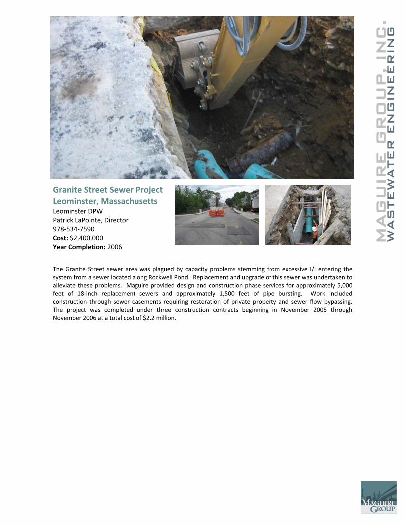
MAG
UIR
E G
RO
UP, IN
WAS
TEW
ATER
EN
GIN
EER
ING
C
.
Granite Street Sewer Project Leominster, Massachusetts Leominster DPW Patrick LaPointe, Director 978‐534‐7590 Cost: $2,400,000 Year Completion: 2006
The Granite Street sewer area was plagued by capacity problems stemming from excessive I/I entering the system from a sewer located along Rockwell Pond. Replacement and upgrade of this sewer was undertaken to alleviate these problems. Maguire provided design and construction phase services for approximately 5,000 feet of 18‐inch replacement sewers and approximately 1,500 feet of pipe bursting. Work included construction through sewer easements requiring restoration of private property and sewer flow bypassing. The project was completed under three construction contracts beginning in November 2005 through November 2006 at a total cost of $2.2 million.
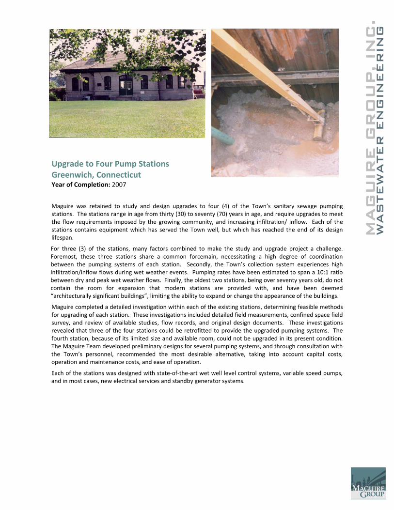
C.
MAG
UIR
E G
RO
UP, IN
WAS
TEW
ATER
EN
GIN
EER
ING
Upgrade to Four Pump Stations Greenwich, Connecticut Year of Completion: 2007
Maguire was retained to study and design upgrades to four (4) of the Town’s sanitary sewage pumping stations. The stations range in age from thirty (30) to seventy (70) years in age, and require upgrades to meet the flow requirements imposed by the growing community, and increasing infiltration/ inflow. Each of the stations contains equipment which has served the Town well, but which has reached the end of its design lifespan.
For three (3) of the stations, many factors combined to make the study and upgrade project a challenge. Foremost, these three stations share a common forcemain, necessitating a high degree of coordination between the pumping systems of each station. Secondly, the Town’s collection system experiences high infiltration/inflow flows during wet weather events. Pumping rates have been estimated to span a 10:1 ratio between dry and peak wet weather flows. Finally, the oldest two stations, being over seventy years old, do not contain the room for expansion that modern stations are provided with, and have been deemed “architecturally significant buildings”, limiting the ability to expand or change the appearance of the buildings.
Maguire completed a detailed investigation within each of the existing stations, determining feasible methods for upgrading of each station. These investigations included detailed field measurements, confined space field survey, and review of available studies, flow records, and original design documents. These investigations revealed that three of the four stations could be retrofitted to provide the upgraded pumping systems. The fourth station, because of its limited size and available room, could not be upgraded in its present condition. The Maguire Team developed preliminary designs for several pumping systems, and through consultation with the Town’s personnel, recommended the most desirable alternative, taking into account capital costs, operation and maintenance costs, and ease of operation.
Each of the stations was designed with state‐of‐the‐art wet well level control systems, variable speed pumps, and in most cases, new electrical services and standby generator systems.
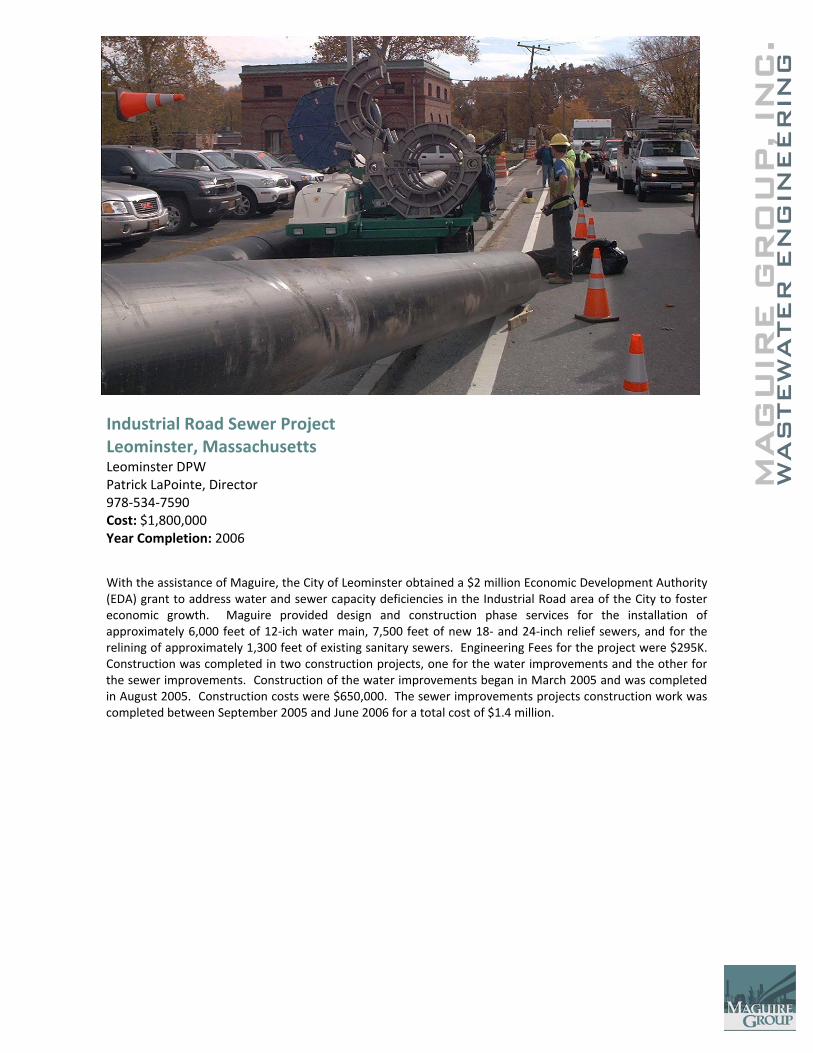
MAG
UIR
E G
RO
UP, IN
WAS
TEW
ATER
EN
GIN
EER
ING
C
.
Industrial Road Sewer Project Leominster, Massachusetts Leominster DPW Patrick LaPointe, Director 978‐534‐7590 Cost: $1,800,000 Year Completion: 2006
With the assistance of Maguire, the City of Leominster obtained a $2 million Economic Development Authority (EDA) grant to address water and sewer capacity deficiencies in the Industrial Road area of the City to foster economic growth. Maguire provided design and construction phase services for the installation of approximately 6,000 feet of 12‐ich water main, 7,500 feet of new 18‐ and 24‐inch relief sewers, and for the relining of approximately 1,300 feet of existing sanitary sewers. Engineering Fees for the project were $295K. Construction was completed in two construction projects, one for the water improvements and the other for the sewer improvements. Construction of the water improvements began in March 2005 and was completed in August 2005. Construction costs were $650,000. The sewer improvements projects construction work was completed between September 2005 and June 2006 for a total cost of $1.4 million.
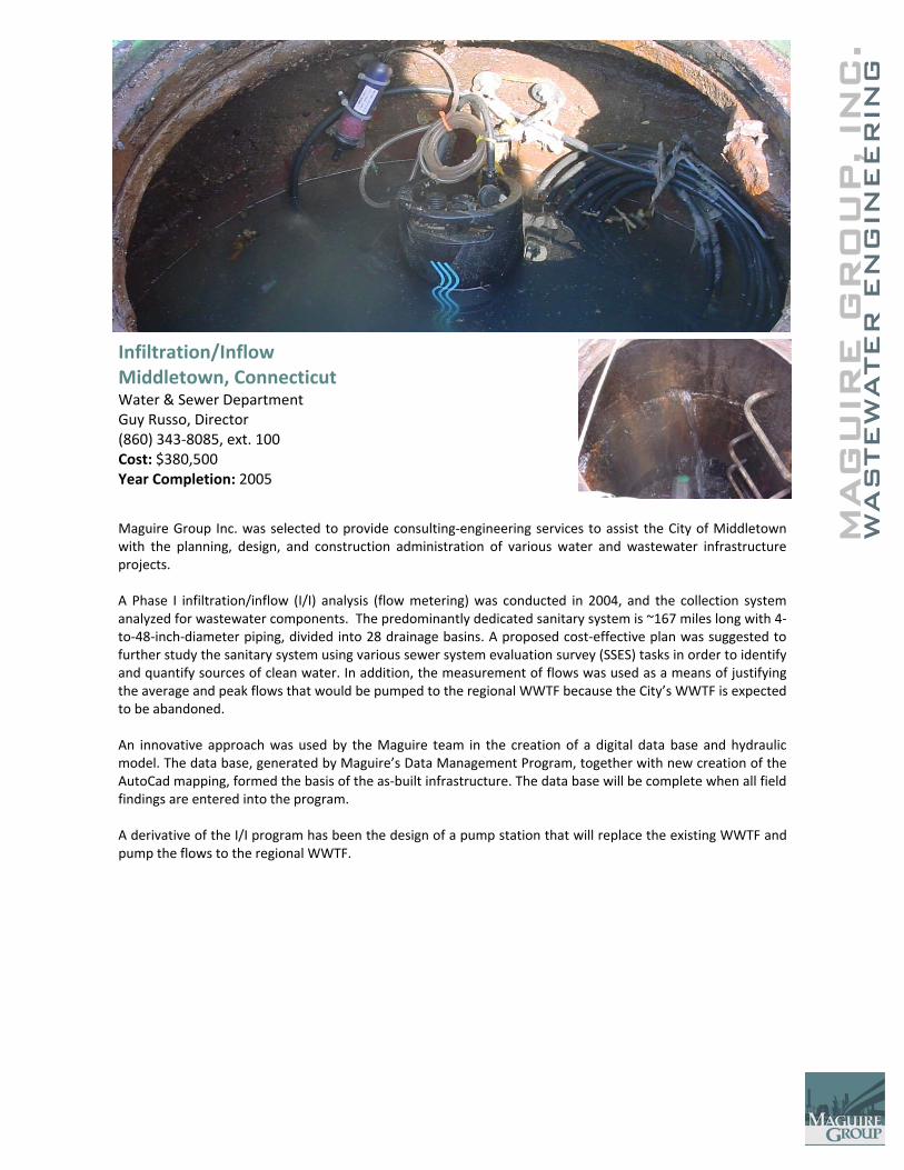
C.
MAG
UIR
E G
RO
UP, IN
WAS
TEW
ATER
EN
GIN
EER
ING
Infiltration/Inflow Middletown, Connecticut Water & Sewer Department Guy Russo, Director (860) 343‐8085, ext. 100 Cost: $380,500 Year Completion: 2005
Maguire Group Inc. was selected to provide consulting‐engineering services to assist the City of Middletown with the planning, design, and construction administration of various water and wastewater infrastructure projects. A Phase I infiltration/inflow (I/I) analysis (flow metering) was conducted in 2004, and the collection system analyzed for wastewater components. The predominantly dedicated sanitary system is ~167 miles long with 4‐to‐48‐inch‐diameter piping, divided into 28 drainage basins. A proposed cost‐effective plan was suggested to further study the sanitary system using various sewer system evaluation survey (SSES) tasks in order to identify and quantify sources of clean water. In addition, the measurement of flows was used as a means of justifying the average and peak flows that would be pumped to the regional WWTF because the City’s WWTF is expected to be abandoned. An innovative approach was used by the Maguire team in the creation of a digital data base and hydraulic model. The data base, generated by Maguire’s Data Management Program, together with new creation of the AutoCad mapping, formed the basis of the as‐built infrastructure. The data base will be complete when all field findings are entered into the program. A derivative of the I/I program has been the design of a pump station that will replace the existing WWTF and pump the flows to the regional WWTF.
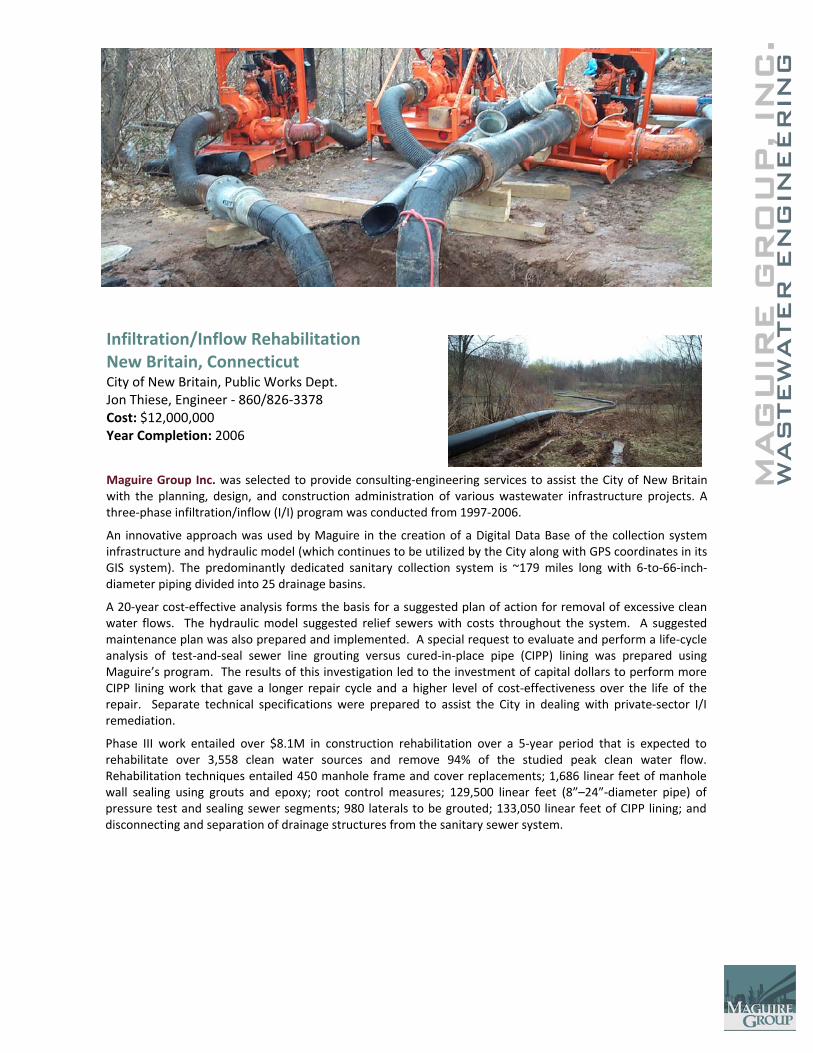
C.
MAG
UIR
E G
RO
UP, IN
WAS
TEW
ATER
EN
GIN
EER
ING
Infiltration/Inflow Rehabilitation New Britain, Connecticut City of New Britain, Public Works Dept. Jon Thiese, Engineer ‐ 860/826‐3378 Cost: $12,000,000 Year Completion: 2006
Maguire Group Inc. was selected to provide consulting‐engineering services to assist the City of New Britain with the planning, design, and construction administration of various wastewater infrastructure projects. A three‐phase infiltration/inflow (I/I) program was conducted from 1997‐2006.
An innovative approach was used by Maguire in the creation of a Digital Data Base of the collection system infrastructure and hydraulic model (which continues to be utilized by the City along with GPS coordinates in its GIS system). The predominantly dedicated sanitary collection system is ~179 miles long with 6‐to‐66‐inch‐diameter piping divided into 25 drainage basins.
A 20‐year cost‐effective analysis forms the basis for a suggested plan of action for removal of excessive clean water flows. The hydraulic model suggested relief sewers with costs throughout the system. A suggested maintenance plan was also prepared and implemented. A special request to evaluate and perform a life‐cycle analysis of test‐and‐seal sewer line grouting versus cured‐in‐place pipe (CIPP) lining was prepared using Maguire’s program. The results of this investigation led to the investment of capital dollars to perform more CIPP lining work that gave a longer repair cycle and a higher level of cost‐effectiveness over the life of the repair. Separate technical specifications were prepared to assist the City in dealing with private‐sector I/I remediation.
Phase III work entailed over $8.1M in construction rehabilitation over a 5‐year period that is expected to rehabilitate over 3,558 clean water sources and remove 94% of the studied peak clean water flow. Rehabilitation techniques entailed 450 manhole frame and cover replacements; 1,686 linear feet of manhole wall sealing using grouts and epoxy; root control measures; 129,500 linear feet (8”–24”‐diameter pipe) of pressure test and sealing sewer segments; 980 laterals to be grouted; 133,050 linear feet of CIPP lining; and disconnecting and separation of drainage structures from the sanitary sewer system.
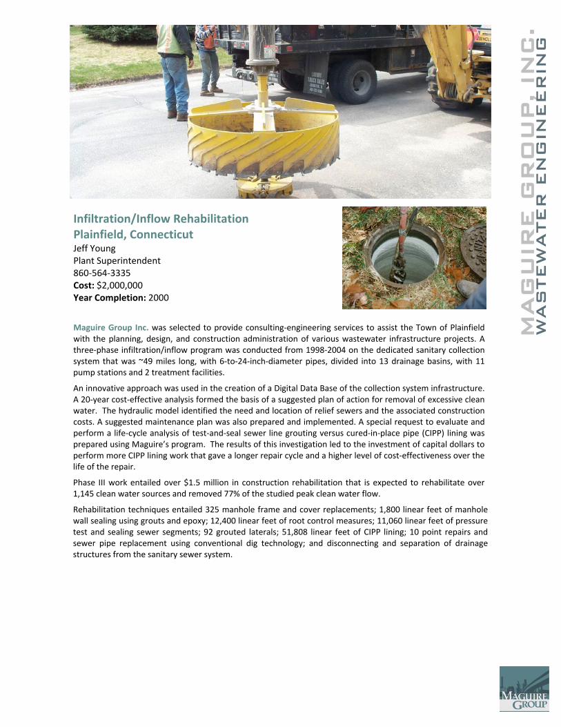
C.
MAG
UIR
E G
RO
UP, IN
WAS
TEW
ATER
EN
GIN
EER
ING
Infiltration/Inflow Rehabilitation Plainfield, Connecticut Jeff Young Plant Superintendent 860‐564‐3335 Cost: $2,000,000 Year Completion: 2000 Maguire Group Inc. was selected to provide consulting‐engineering services to assist the Town of Plainfield with the planning, design, and construction administration of various wastewater infrastructure projects. A three‐phase infiltration/inflow program was conducted from 1998‐2004 on the dedicated sanitary collection system that was ~49 miles long, with 6‐to‐24‐inch‐diameter pipes, divided into 13 drainage basins, with 11 pump stations and 2 treatment facilities.
An innovative approach was used in the creation of a Digital Data Base of the collection system infrastructure. A 20‐year cost‐effective analysis formed the basis of a suggested plan of action for removal of excessive clean water. The hydraulic model identified the need and location of relief sewers and the associated construction costs. A suggested maintenance plan was also prepared and implemented. A special request to evaluate and perform a life‐cycle analysis of test‐and‐seal sewer line grouting versus cured‐in‐place pipe (CIPP) lining was prepared using Maguire’s program. The results of this investigation led to the investment of capital dollars to perform more CIPP lining work that gave a longer repair cycle and a higher level of cost‐effectiveness over the life of the repair.
Phase III work entailed over $1.5 million in construction rehabilitation that is expected to rehabilitate over 1,145 clean water sources and removed 77% of the studied peak clean water flow.
Rehabilitation techniques entailed 325 manhole frame and cover replacements; 1,800 linear feet of manhole wall sealing using grouts and epoxy; 12,400 linear feet of root control measures; 11,060 linear feet of pressure test and sealing sewer segments; 92 grouted laterals; 51,808 linear feet of CIPP lining; 10 point repairs and sewer pipe replacement using conventional dig technology; and disconnecting and separation of drainage structures from the sanitary sewer system.
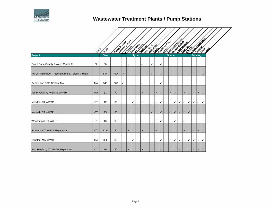
Wastewater Treatment Plants / Pump Stations
State
MGD
Pump Station
Capac
ity-M
GD
Primary
Secondary
Advance
dPac
kage
Municipal
Industrial
StudyFac
ilities
Plan
Design
Computer U
sage
Ocean
Outfa
ll
O&M Man
ual
Start-U
pCM/C
EIGran
t Applic
ation
Federa
lStat
eLoca
l
Type FundingScopeProject Size
South Dade County Project, Miami, FL FL 50
PA-LI Wastewater Treatment Plant, Taipeil, Taiwan 844 N/A
Deer Island STP, Boston, MA MA 343 600
Fall River, MA, Regional WWTP MA 31 70
Meriden, CT WWTP CT 12 36
Norwalk, CT WWTP CT 15 35
Woonsocket, RI WWTP RI 16 35
Stratford, CT, WPCP Expansion CT 11.5 30
Taunton, MA WWTF MA 8.4 30
East Hartford, CT WPCP, Expansion CT 10 30
Type FundingScope
Page 1
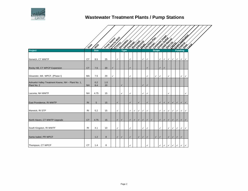
Wastewater Treatment Plants / Pump Stations
State
MGD
Pump Station
Capac
ity-M
GD
Primary
Secondary
Advance
dPac
kage
Municipal
Industrial
StudyFac
ilities
Plan
Design
Computer U
sage
Ocean
Outfa
ll
O&M Man
ual
Start-U
pCM/C
EIGran
t Applic
ation
Federa
lStat
eLoca
l
Type FundingScopeProject Size Type FundingScope
Norwich, CT WWTP CT 8.5 25
Rocky Hill, CT WPCP Expansion CT 7.5 20
Glouester, MA WPCF, (Phase I) MA 7.5 20
Ashuelot Valley Treatment Keene, NH – Plant No. 1, Plant No. 2 NH
0.28.4
1.020
Laconia, NH WWTF NH 4.75 15
East Providence, RI WWTP RI 5 15
Warwick, RI STP RI 5.2 15
North Haven, CT WWTP Upgrade CT 4.75 15
South Kingston, RI WWTF RI 4.1 10
Santa Isabel, PR WPCF 1.2 8
Thompson, CT WPCP CT 1.4 8
Page 2

Wastewater Treatment Plants / Pump Stations
State
MGD
Pump Station
Capac
ity-M
GD
Primary
Secondary
Advance
dPac
kage
Municipal
Industrial
StudyFac
ilities
Plan
Design
Computer U
sage
Ocean
Outfa
ll
O&M Man
ual
Start-U
pCM/C
EIGran
t Applic
ation
Federa
lStat
eLoca
l
Type FundingScopeProject Size Type FundingScope
Montpelier, VT WPCP VT 2.4 7
Plymouth, CT WPCF CT 1.75 6
Plainfield, CT WWTP CT 1.75 6
East Greenwich, RI STP Expansion RI 1.75 6
Thomaston, CT WPCP Expansion CT 1.2 5
Bennington, VT WWTP VT 1.5 4.5
Litchfield, CT WPCP CT 0.8 3
Hatfield, MA WPCF MA 0.5 3
Burrilville, RI STP RI 1 3
Warren, RI STP RI 0.5 1.5
Westerly, RI STP RI 0.5 1.5
Page 3
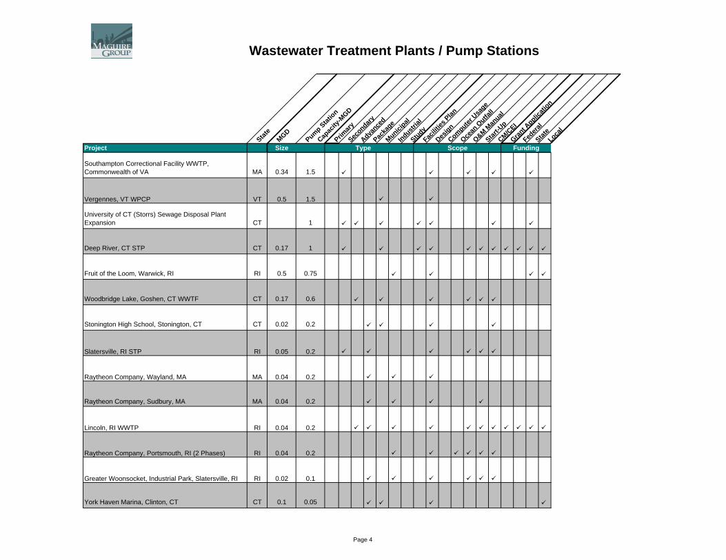
Wastewater Treatment Plants / Pump Stations
State
MGD
Pump Station
Capac
ity-M
GD
Primary
Secondary
Advance
dPac
kage
Municipal
Industrial
StudyFac
ilities
Plan
Design
Computer U
sage
Ocean
Outfa
ll
O&M Man
ual
Start-U
pCM/C
EIGran
t Applic
ation
Federa
lStat
eLoca
l
Type FundingScopeProject Size Type FundingScope
Southampton Correctional Facility WWTP, Commonwealth of VA MA 0.34 1.5
Vergennes, VT WPCP VT 0.5 1.5
University of CT (Storrs) Sewage Disposal Plant Expansion CT 1
Deep River, CT STP CT 0.17 1
Fruit of the Loom, Warwick, RI RI 0.5 0.75
Woodbridge Lake, Goshen, CT WWTF CT 0.17 0.6
Stonington High School, Stonington, CT CT 0.02 0.2
Slatersville, RI STP RI 0.05 0.2
Raytheon Company, Wayland, MA MA 0.04 0.2
Raytheon Company, Sudbury, MA MA 0.04 0.2
Lincoln, RI WWTP RI 0.04 0.2
Raytheon Company, Portsmouth, RI (2 Phases) RI 0.04 0.2
Greater Woonsocket, Industrial Park, Slatersville, RI RI 0.02 0.1
York Haven Marina, Clinton, CT CT 0.1 0.05
Page 4
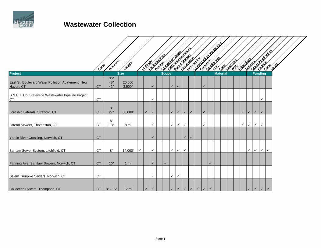
Wastewater Collection
State
Diamete
rLen
gth
I/I Study
Facilit
ies Plan
Design
Computer U
sage
CSO Impro
vemen
ts
Pump Station
Force M
ainInter
ceptor
Constructi
on Insp
ectio
n
Concrete
Ductile
Iron
Clay Steel
Cast Ir
onPVCFiberg
lass
TunnelsGran
t Applic
ation
Federa
lStat
eLoca
l
Size FundingMaterialScopeProject
East St. Boulevard Water Pollution Abatement, New Haven, CT CT
36"48"42"
20,0003,500"
S.N.E.T. Co. Statewide Wastewater Pipeline Project CT CT
Lordship Laterals, Stratford, CT CT8"
27" 80,000'
Lateral Sewers, Thomaston, CT CT8"
18" 8 mi
Yantic River Crossing, Norwich, CT CT
Bantam Sewer System, Litchfield, CT CT 8" 14,000'
Fanning Ave. Sanitary Sewers, Norwich, CT CT 10" 1 mi
Salem Turnpike Sewers, Norwich, CT CT
Collection System, Thompson, CT CT 8" - 15" 12 mi
Size FundingMaterialScope
Page 1
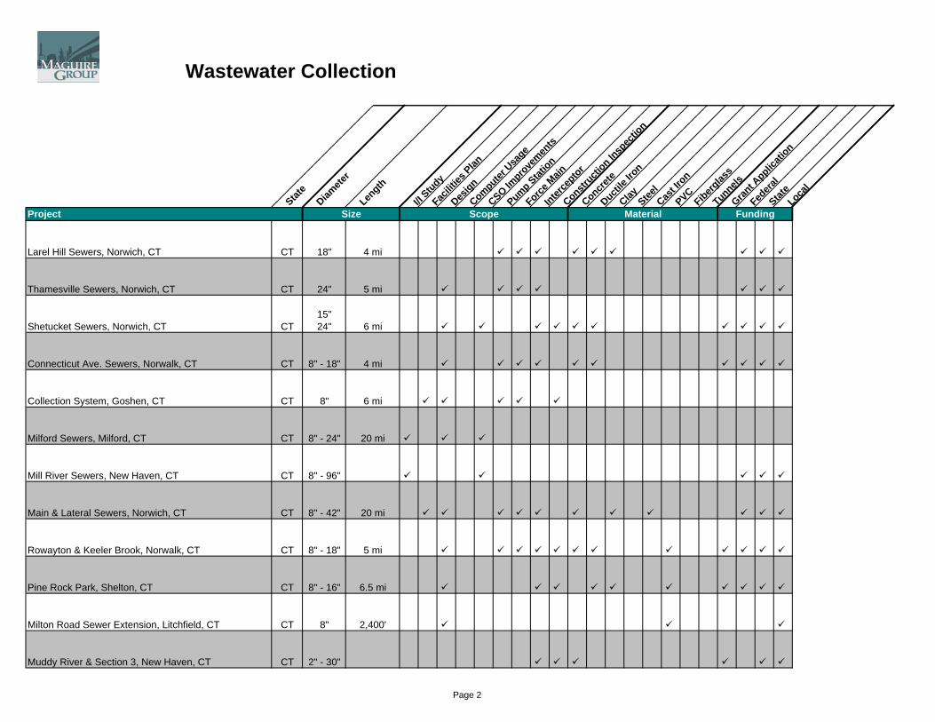
Wastewater Collection
State
Diamete
rLen
gth
I/I Study
Facilit
ies Plan
Design
Computer U
sage
CSO Impro
vemen
ts
Pump Station
Force M
ainInter
ceptor
Constructi
on Insp
ectio
n
Concrete
Ductile
Iron
Clay Steel
Cast Ir
onPVCFiberg
lass
TunnelsGran
t Applic
ation
Federa
lStat
eLoca
l
Size FundingMaterialScopeProject Size FundingMaterialScope
Larel Hill Sewers, Norwich, CT CT 18" 4 mi
Thamesville Sewers, Norwich, CT CT 24" 5 mi
Shetucket Sewers, Norwich, CT CT15"24" 6 mi
Connecticut Ave. Sewers, Norwalk, CT CT 8" - 18" 4 mi
Collection System, Goshen, CT CT 8" 6 mi
Milford Sewers, Milford, CT CT 8" - 24" 20 mi
Mill River Sewers, New Haven, CT CT 8" - 96"
Main & Lateral Sewers, Norwich, CT CT 8" - 42" 20 mi
Rowayton & Keeler Brook, Norwalk, CT CT 8" - 18" 5 mi
Pine Rock Park, Shelton, CT CT 8" - 16" 6.5 mi
Milton Road Sewer Extension, Litchfield, CT CT 8" 2,400'
Muddy River & Section 3, New Haven, CT CT 2" - 30"
Page 2

Wastewater Collection
State
Diamete
rLen
gth
I/I Study
Facilit
ies Plan
Design
Computer U
sage
CSO Impro
vemen
ts
Pump Station
Force M
ainInter
ceptor
Constructi
on Insp
ectio
n
Concrete
Ductile
Iron
Clay Steel
Cast Ir
onPVCFiberg
lass
TunnelsGran
t Applic
ation
Federa
lStat
eLoca
l
Size FundingMaterialScopeProject Size FundingMaterialScope
Collection System, Deep River, CT CT 8" - 16" 21,000'
Harbor Crossing, New Haven, CT CT (2) 42" (2) 1,000'
Sewer Separation, Shelton, CT CT 8" - 24"17,900'26,700'
Glen Street Slip Lining, New Britain, CT CT 8" 3,000'
Montowese Laturals, North Haven, CT CT 8"
Huntington Sewers, Shelton, CT CT 8" - 15" 20,000'
Route 202 Sewers, Litchfield, CT CT 8" 8,100'
Phase III Rehabilitation, Meriden, CT CT 8" - 24"
Quinnipiac River Crossing, New Haven, CT CT 8" 3,000'
Shepaug River Crossing, Litchfield, CT CT 8" - 20" 30,000'
Charles River Estuary CrossingCambridge-Boston, MA MA 60" 500'
Miller's River CrossingCambridge, MA MA 96" 2,000'
Page 3

Wastewater Collection
State
Diamete
rLen
gth
I/I Study
Facilit
ies Plan
Design
Computer U
sage
CSO Impro
vemen
ts
Pump Station
Force M
ainInter
ceptor
Constructi
on Insp
ectio
n
Concrete
Ductile
Iron
Clay Steel
Cast Ir
onPVCFiberg
lass
TunnelsGran
t Applic
ation
Federa
lStat
eLoca
l
Size FundingMaterialScopeProject Size FundingMaterialScope
Slip Lining Project, Fall River, MA MA33,500'60,000
South End Project Sewage & Storm Drainage, Boston, MA MA
10"6" 17 mi
Sewer Reconstruction, Cambridge, MA MA
8"24"10' 91,000'
Deer Island Collection, Boston, MA MA11.5'10'
4 mi4 mi5 mi
Sewage Collection System, Taunton, MA MA8"
24" 25,000'
Marginal Conduit Sewer Screening, Somerville, MA MA 84" 2,600'
Sewer/Drainage, Salem, MA MA8"
30" 10 mi
N. Charles Relief Sewer, Cambridge, MA MA 6" 1.5 mi
Lake Quinsigamond Sewer Rehabilitation, Worcester, MA MA 8" - 42" 6 mi
Page 4
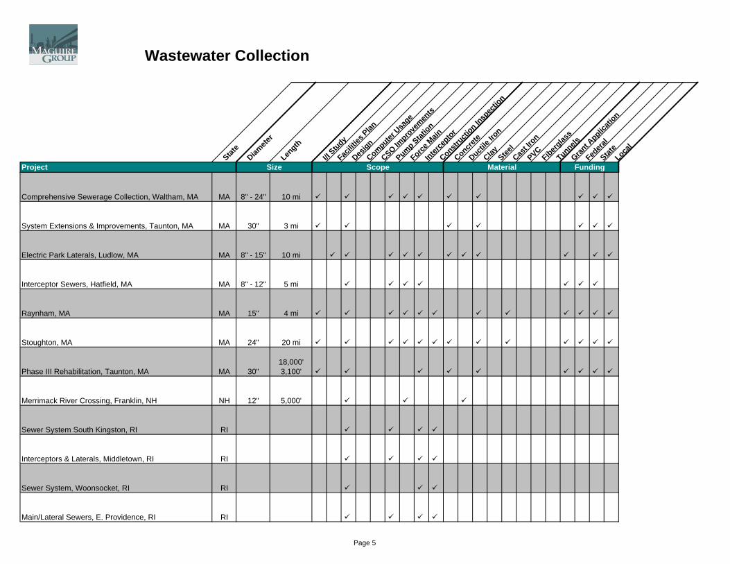
Wastewater Collection
State
Diamete
rLen
gth
I/I Study
Facilit
ies Plan
Design
Computer U
sage
CSO Impro
vemen
ts
Pump Station
Force M
ainInter
ceptor
Constructi
on Insp
ectio
n
Concrete
Ductile
Iron
Clay Steel
Cast Ir
onPVCFiberg
lass
TunnelsGran
t Applic
ation
Federa
lStat
eLoca
l
Size FundingMaterialScopeProject Size FundingMaterialScope
Comprehensive Sewerage Collection, Waltham, MA MA 8" - 24" 10 mi
System Extensions & Improvements, Taunton, MA MA 30" 3 mi
Electric Park Laterals, Ludlow, MA MA 8" - 15" 10 mi
Interceptor Sewers, Hatfield, MA MA 8" - 12" 5 mi
Raynham, MA MA 15" 4 mi
Stoughton, MA MA 24" 20 mi
Phase III Rehabilitation, Taunton, MA MA 30"18,000'3,100'
Merrimack River Crossing, Franklin, NH NH 12" 5,000'
Sewer System South Kingston, RI RI
Interceptors & Laterals, Middletown, RI RI
Sewer System, Woonsocket, RI RI
Main/Lateral Sewers, E. Providence, RI RI
Page 5

Wastewater Collection
State
Diamete
rLen
gth
I/I Study
Facilit
ies Plan
Design
Computer U
sage
CSO Impro
vemen
ts
Pump Station
Force M
ainInter
ceptor
Constructi
on Insp
ectio
n
Concrete
Ductile
Iron
Clay Steel
Cast Ir
onPVCFiberg
lass
TunnelsGran
t Applic
ation
Federa
lStat
eLoca
l
Size FundingMaterialScopeProject Size FundingMaterialScope
Bald Hill Sewer, Line Warwick, RI RI
Collection Facilities, Burrillville, RI RI
Sewage Collection, Westerly, RI RI 20 mi
Hoxie Laterals, Warwick, RI RI 12" 2 mi
Pawtuxet Sewers, Warwick, RI RI 15" 5 mi
Pawtuxet River Crossing, Warwick, RI RI 12" 100'
North End Salt Pond Crossing, S. Kingston, RI RI 8" - 24"17,900'26,700'
Page 6

Wastewater Collection
State
Diamete
rLen
gth
I/I Study
Facilit
ies Plan
Design
Computer U
sage
CSO Impro
vemen
ts
Pump Station
Force M
ainInter
ceptor
Constructi
on Insp
ectio
n
Concrete
Ductile
Iron
Clay Steel
Cast Ir
onPVCFiberg
lass
TunnelsGran
t Applic
ation
Federa
lStat
eLoca
l
Size FundingMaterialScopeProject Size FundingMaterialScope
Hunt's River Crossing, E. Providence, RI RI 8" 8,100'
Woonasquatucket River, Johnston, RI RI 4" - 8" 12,000'
Wastewater System Improvements, Cheasapeake, VA VA 8" 22.5 mi
Sewer System Buelah Road, Henrico County, VA VA 24" 12,000'
VA Dept. of Corrections, Southampton Corr. Ctr, Lorton, VA VA 8" 3,200'
Southampton Correc. Unit, Southampton County, VA VA 8" 3,200'
Monticello Storm Sewers, Albemarle County, VA VA 66" 1,600'
Albemarle County, VA VA 8" - 20" 30,000'
Anne Arundel County, VA VA 12" 5,000'
Hanover County, VA VA 4" - 8" 12,000'
Polaski Correction Unit, Commonwealth of VA VA 15" 4 mi
Stafford Correctional Unit, Commonwealth of VA VA 24" 20 mi
Page 7
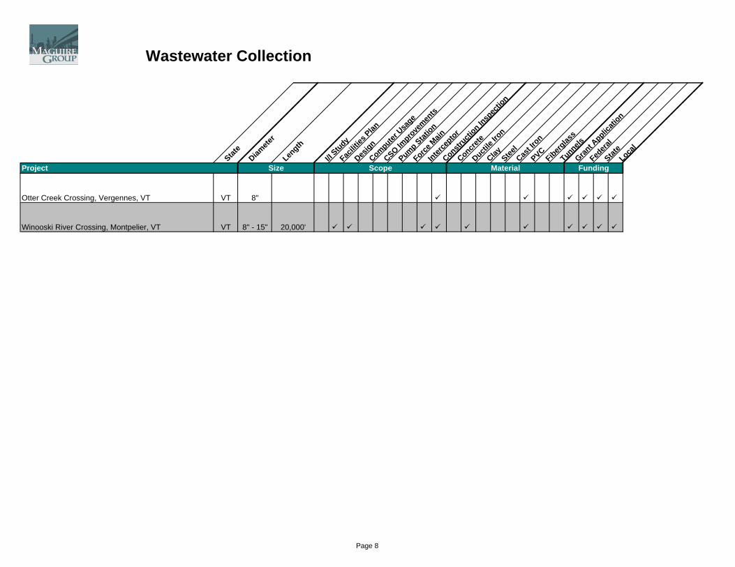
Wastewater Collection
State
Diamete
rLen
gth
I/I Study
Facilit
ies Plan
Design
Computer U
sage
CSO Impro
vemen
ts
Pump Station
Force M
ainInter
ceptor
Constructi
on Insp
ectio
n
Concrete
Ductile
Iron
Clay Steel
Cast Ir
onPVCFiberg
lass
TunnelsGran
t Applic
ation
Federa
lStat
eLoca
l
Size FundingMaterialScopeProject Size FundingMaterialScope
Otter Creek Crossing, Vergennes, VT VT 8"
Winooski River Crossing, Montpelier, VT VT 8" - 15" 20,000'
Page 8
MAG
UIR
E G
RO
UP, IN
TAB
LE O
F C
ON
TEN
TS
C
.
Section I Company Overview Section II Water Engineering Section III Wastewater Engineering Section IV Dam Engineering

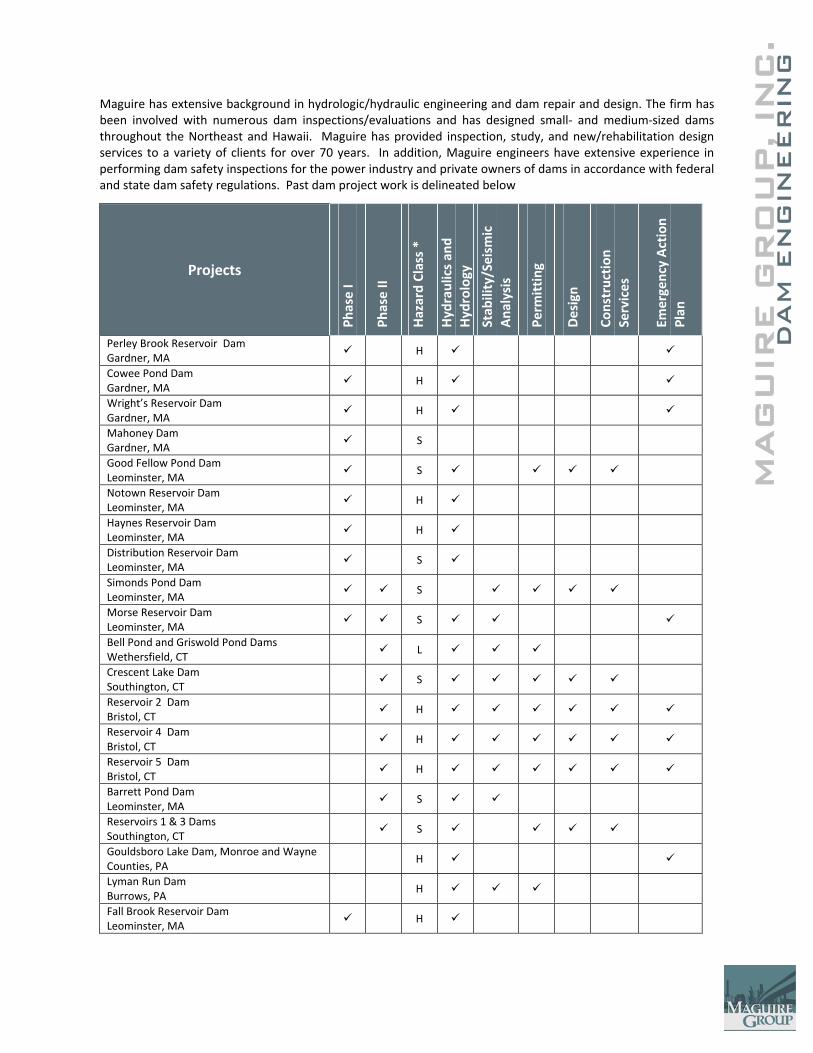
MAG
UIR
E G
RO
UP, IN
DAM
EN
GIN
EER
ING
C
.
Maguire has extensive background in hydrologic/hydraulic engineering and dam repair and design. The firm has been involved with numerous dam inspections/evaluations and has designed small‐ and medium‐sized dams throughout the Northeast and Hawaii. Maguire has provided inspection, study, and new/rehabilitation design services to a variety of clients for over 70 years. In addition, Maguire engineers have extensive experience in performing dam safety inspections for the power industry and private owners of dams in accordance with federal and state dam safety regulations. Past dam project work is delineated below
Projects
Phase I
Phase II
Hazard Class *
Hydraulics an
d Hydrology
Stab
ility/Seism
ic
Ana
lysis
Perm
itting
Design
Construction
Services
Emergency Action
Plan
Perley Brook Reservoir Dam Gardner, MA
H
Cowee Pond Dam Gardner, MA
H
Wright’s Reservoir Dam Gardner, MA
H
Mahoney Dam Gardner, MA
S
Good Fellow Pond Dam Leominster, MA
S
Notown Reservoir Dam Leominster, MA
H
Haynes Reservoir Dam Leominster, MA
H
Distribution Reservoir Dam Leominster, MA
S
Simonds Pond Dam Leominster, MA
S
Morse Reservoir Dam Leominster, MA
S
Bell Pond and Griswold Pond Dams Wethersfield, CT
L
Crescent Lake Dam Southington, CT
S
Reservoir 2 Dam Bristol, CT
H
Reservoir 4 Dam Bristol, CT
H
Reservoir 5 Dam Bristol, CT
H
Barrett Pond Dam Leominster, MA
S
Reservoirs 1 & 3 Dams Southington, CT
S
Gouldsboro Lake Dam, Monroe and Wayne Counties, PA
H
Lyman Run Dam Burrows, PA
H
Fall Brook Reservoir Dam Leominster, MA
H
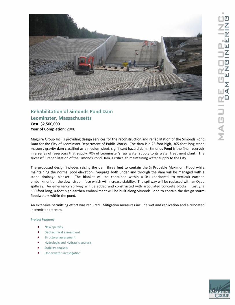
MAG
UIR
E G
RO
UP, IN
DAM
EN
GIN
EER
ING
C
.
Rehabilitation of Simonds Pond Dam Leominster, Massachusetts Cost: $2,500,000 Year of Completion: 2006 Maguire Group Inc. is providing design services for the reconstruction and rehabilitation of the Simonds Pond Dam for the City of Leominster Department of Public Works. The dam is a 26‐foot high, 365‐foot long stone masonry gravity dam classified as a medium sized, significant hazard dam. Simonds Pond is the final reservoir in a series of reservoirs that supply 70% of Leominster’s raw water supply to its water treatment plant. The successful rehabilitation of the Simonds Pond Dam is critical to maintaining water supply to the City. The proposed design includes raising the dam three feet to contain the ½ Probable Maximum Flood while maintaining the normal pool elevation. Seepage both under and through the dam will be managed with a stone drainage blanket. The blanket will be contained within a 3:1 (horizontal to vertical) earthen embankment on the downstream face which will increase stability. The spillway will be replaced with an Ogee spillway. An emergency spillway will be added and constructed with articulated concrete blocks. Lastly, a 500‐foot long, 4‐foot high earthen embankment will be built along Simonds Pond to contain the design storm floodwaters within the pond. An extensive permitting effort was required. Mitigation measures include wetland replication and a relocated intermittent stream. Project Features
• New spillway
• Geotechnical assessment
• Structural assessment
• Hydrologic and Hydraulic analysis
• Stability analysis
• Underwater Investigation
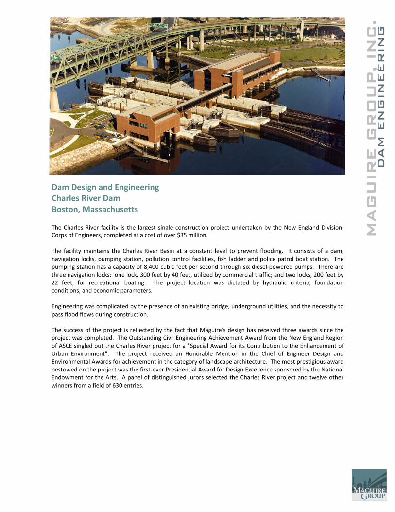
C.
MAG
UIR
E G
RO
UP, IN
DAM
EN
GIN
EER
ING
Dam Design and Engineering Charles River Dam Boston, Massachusetts The Charles River facility is the largest single construction project undertaken by the New England Division, Corps of Engineers, completed at a cost of over $35 million. The facility maintains the Charles River Basin at a constant level to prevent flooding. It consists of a dam, navigation locks, pumping station, pollution control facilities, fish ladder and police patrol boat station. The pumping station has a capacity of 8,400 cubic feet per second through six diesel‐powered pumps. There are three navigation locks: one lock, 300 feet by 40 feet, utilized by commercial traffic; and two locks, 200 feet by 22 feet, for recreational boating. The project location was dictated by hydraulic criteria, foundation conditions, and economic parameters. Engineering was complicated by the presence of an existing bridge, underground utilities, and the necessity to pass flood flows during construction. The success of the project is reflected by the fact that Maguire's design has received three awards since the project was completed. The Outstanding Civil Engineering Achievement Award from the New England Region of ASCE singled out the Charles River project for a "Special Award for its Contribution to the Enhancement of Urban Environment". The project received an Honorable Mention in the Chief of Engineer Design and Environmental Awards for achievement in the category of landscape architecture. The most prestigious award bestowed on the project was the first‐ever Presidential Award for Design Excellence sponsored by the National Endowment for the Arts. A panel of distinguished jurors selected the Charles River project and twelve other winners from a field of 630 entries.
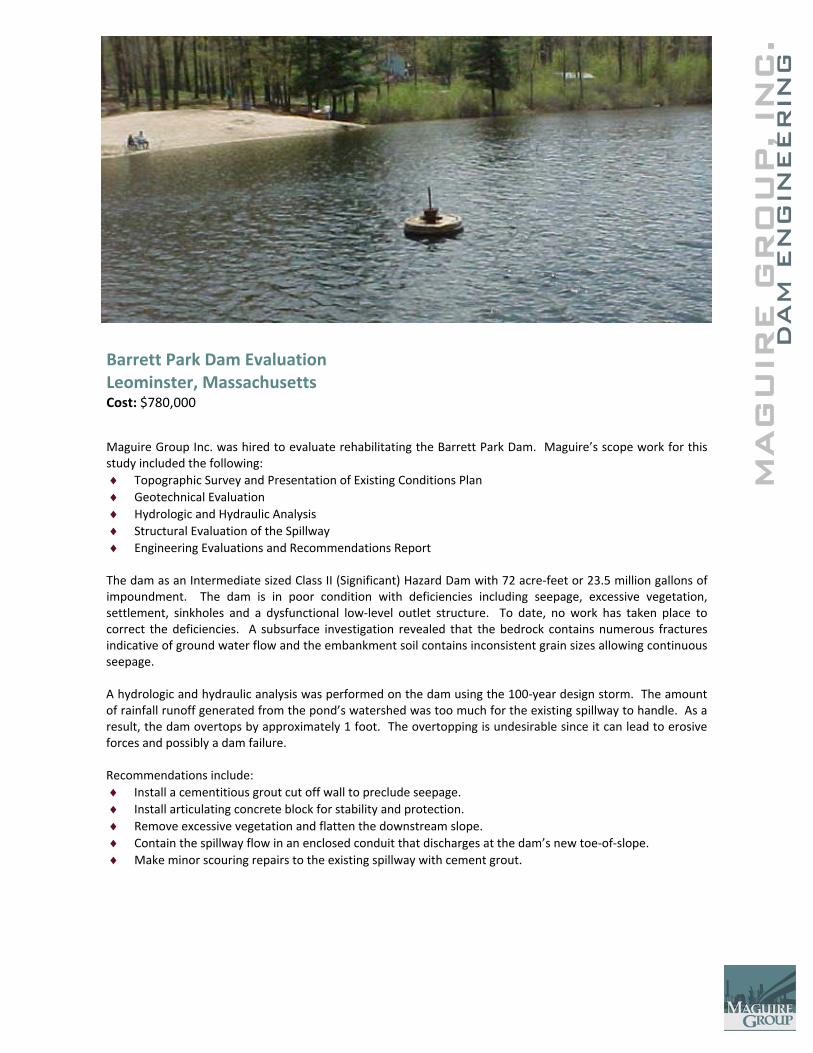
MAG
UIR
E G
RO
UP, IN
DAM
EN
GIN
EER
ING
C
.
Barrett Park Dam Evaluation Leominster, Massachusetts Cost: $780,000
Maguire Group Inc. was hired to evaluate rehabilitating the Barrett Park Dam. Maguire’s scope work for this study included the following: ♦ Topographic Survey and Presentation of Existing Conditions Plan ♦ Geotechnical Evaluation ♦ Hydrologic and Hydraulic Analysis ♦ Structural Evaluation of the Spillway ♦ Engineering Evaluations and Recommendations Report The dam as an Intermediate sized Class II (Significant) Hazard Dam with 72 acre‐feet or 23.5 million gallons of impoundment. The dam is in poor condition with deficiencies including seepage, excessive vegetation, settlement, sinkholes and a dysfunctional low‐level outlet structure. To date, no work has taken place to correct the deficiencies. A subsurface investigation revealed that the bedrock contains numerous fractures indicative of ground water flow and the embankment soil contains inconsistent grain sizes allowing continuous seepage. A hydrologic and hydraulic analysis was performed on the dam using the 100‐year design storm. The amount of rainfall runoff generated from the pond’s watershed was too much for the existing spillway to handle. As a result, the dam overtops by approximately 1 foot. The overtopping is undesirable since it can lead to erosive forces and possibly a dam failure. Recommendations include: ♦ Install a cementitious grout cut off wall to preclude seepage. ♦ Install articulating concrete block for stability and protection. ♦ Remove excessive vegetation and flatten the downstream slope. ♦ Contain the spillway flow in an enclosed conduit that discharges at the dam’s new toe‐of‐slope. ♦ Make minor scouring repairs to the existing spillway with cement grout.

MAG
UIR
E G
RO
UP, IN
DAM
EN
GIN
EER
ING
C
.
Dam Evaluations Leominster, Massachusetts
Maguire Group, Inc. was hired by the City of Leominster, Department of Public Works to perform visual inspections and evaluation reports on seven reservoir dams. The dams included Simonds Pond Dam, Goodfellow Pond Dam, Notown Reservoir Dam, Haynes Reservoir Dam, Distributing Reservoir Dam, Fall Brook Reservoir Dam, and Morse Reservoir Dam. The dams were inspected in accordance with Army Corps of Engineers' requirements, the Massachusetts Department of Conservation and Recreation (DCR), and the requirements set forth in the Code of Massachusetts Regulations (302 CMR 10.00 Dam Safety Rules and Regulations). The purpose of the evaluation is to identify expeditiously those dams which may pose hazards to human life or property. The scope of the work for the Phase I evaluations was divided into four parts: 1) obtain and review all available reports, investigations, and data previously submitted to the DCR, owner, or U.S. Army Corps of Engineers pertaining to each dam and appurtenant structures; 2) perform a visual inspection of each site and completion of the standard dam inspection checklist; 3) evaluate the status and need for an emergency action plan for the site; and 4) prepare and submit a final report presenting the evaluation of each retention structure, including recommendations and remedial action. In addition two of the dams required Phase II evaluations. The evaluation included installation of piezometers to monitor water levels and seepage, performance of a stability analysis, evaluation of hydraulic capacity of the spillway and condition evaluation of the entire structure and appurtenances.
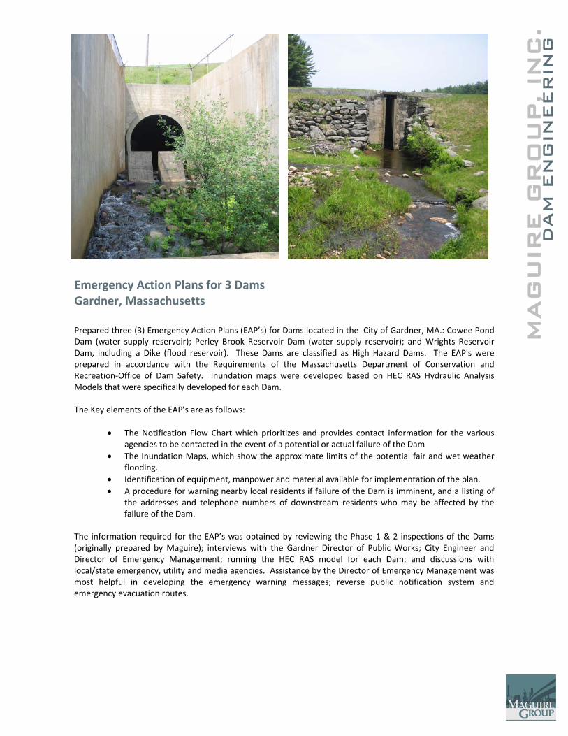
C.
MAG
UIR
E G
RO
UP, IN
DAM
EN
GIN
EER
ING
Emergency Action Plans for 3 Dams Gardner, Massachusetts Prepared three (3) Emergency Action Plans (EAP’s) for Dams located in the City of Gardner, MA.: Cowee Pond Dam (water supply reservoir); Perley Brook Reservoir Dam (water supply reservoir); and Wrights Reservoir Dam, including a Dike (flood reservoir). These Dams are classified as High Hazard Dams. The EAP's were prepared in accordance with the Requirements of the Massachusetts Department of Conservation and Recreation‐Office of Dam Safety. Inundation maps were developed based on HEC RAS Hydraulic Analysis Models that were specifically developed for each Dam. The Key elements of the EAP’s are as follows:
• The Notification Flow Chart which prioritizes and provides contact information for the various agencies to be contacted in the event of a potential or actual failure of the Dam
• The Inundation Maps, which show the approximate limits of the potential fair and wet weather flooding.
• Identification of equipment, manpower and material available for implementation of the plan. • A procedure for warning nearby local residents if failure of the Dam is imminent, and a listing of
the addresses and telephone numbers of downstream residents who may be affected by the failure of the Dam.
The information required for the EAP’s was obtained by reviewing the Phase 1 & 2 inspections of the Dams (originally prepared by Maguire); interviews with the Gardner Director of Public Works; City Engineer and Director of Emergency Management; running the HEC RAS model for each Dam; and discussions with local/state emergency, utility and media agencies. Assistance by the Director of Emergency Management was most helpful in developing the emergency warning messages; reverse public notification system and emergency evacuation routes.
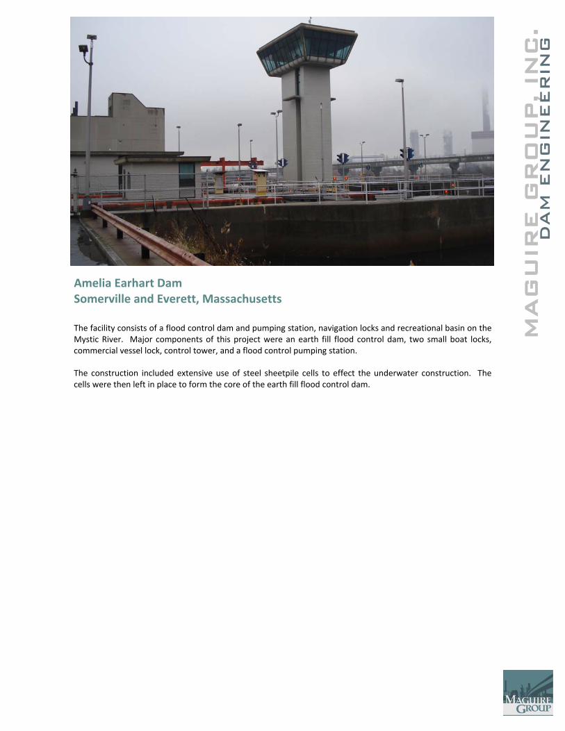
MAG
UIR
E G
RO
UP, IN
DAM
EN
GIN
EER
ING
C
.
Amelia Earhart Dam Somerville and Everett, Massachusetts The facility consists of a flood control dam and pumping station, navigation locks and recreational basin on the Mystic River. Major components of this project were an earth fill flood control dam, two small boat locks, commercial vessel lock, control tower, and a flood control pumping station. The construction included extensive use of steel sheetpile cells to effect the underwater construction. The cells were then left in place to form the core of the earth fill flood control dam.
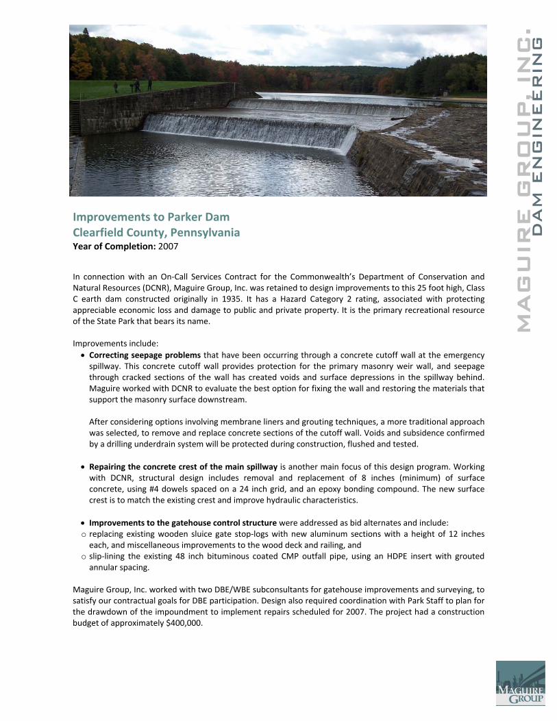
MAG
UIR
E G
RO
UP, IN
DAM
EN
GIN
EER
ING
C
.
Improvements to Parker Dam Clearfield County, Pennsylvania Year of Completion: 2007
In connection with an On‐Call Services Contract for the Commonwealth’s Department of Conservation and Natural Resources (DCNR), Maguire Group, Inc. was retained to design improvements to this 25 foot high, Class C earth dam constructed originally in 1935. It has a Hazard Category 2 rating, associated with protecting appreciable economic loss and damage to public and private property. It is the primary recreational resource of the State Park that bears its name. Improvements include: • Correcting seepage problems that have been occurring through a concrete cutoff wall at the emergency spillway. This concrete cutoff wall provides protection for the primary masonry weir wall, and seepage through cracked sections of the wall has created voids and surface depressions in the spillway behind. Maguire worked with DCNR to evaluate the best option for fixing the wall and restoring the materials that support the masonry surface downstream.
After considering options involving membrane liners and grouting techniques, a more traditional approach was selected, to remove and replace concrete sections of the cutoff wall. Voids and subsidence confirmed by a drilling underdrain system will be protected during construction, flushed and tested.
• Repairing the concrete crest of the main spillway is another main focus of this design program. Working with DCNR, structural design includes removal and replacement of 8 inches (minimum) of surface concrete, using #4 dowels spaced on a 24 inch grid, and an epoxy bonding compound. The new surface crest is to match the existing crest and improve hydraulic characteristics.
• Improvements to the gatehouse control structure were addressed as bid alternates and include: o replacing existing wooden sluice gate stop‐logs with new aluminum sections with a height of 12 inches each, and miscellaneous improvements to the wood deck and railing, and
o slip‐lining the existing 48 inch bituminous coated CMP outfall pipe, using an HDPE insert with grouted annular spacing.
Maguire Group, Inc. worked with two DBE/WBE subconsultants for gatehouse improvements and surveying, to satisfy our contractual goals for DBE participation. Design also required coordination with Park Staff to plan for the drawdown of the impoundment to implement repairs scheduled for 2007. The project had a construction budget of approximately $400,000.
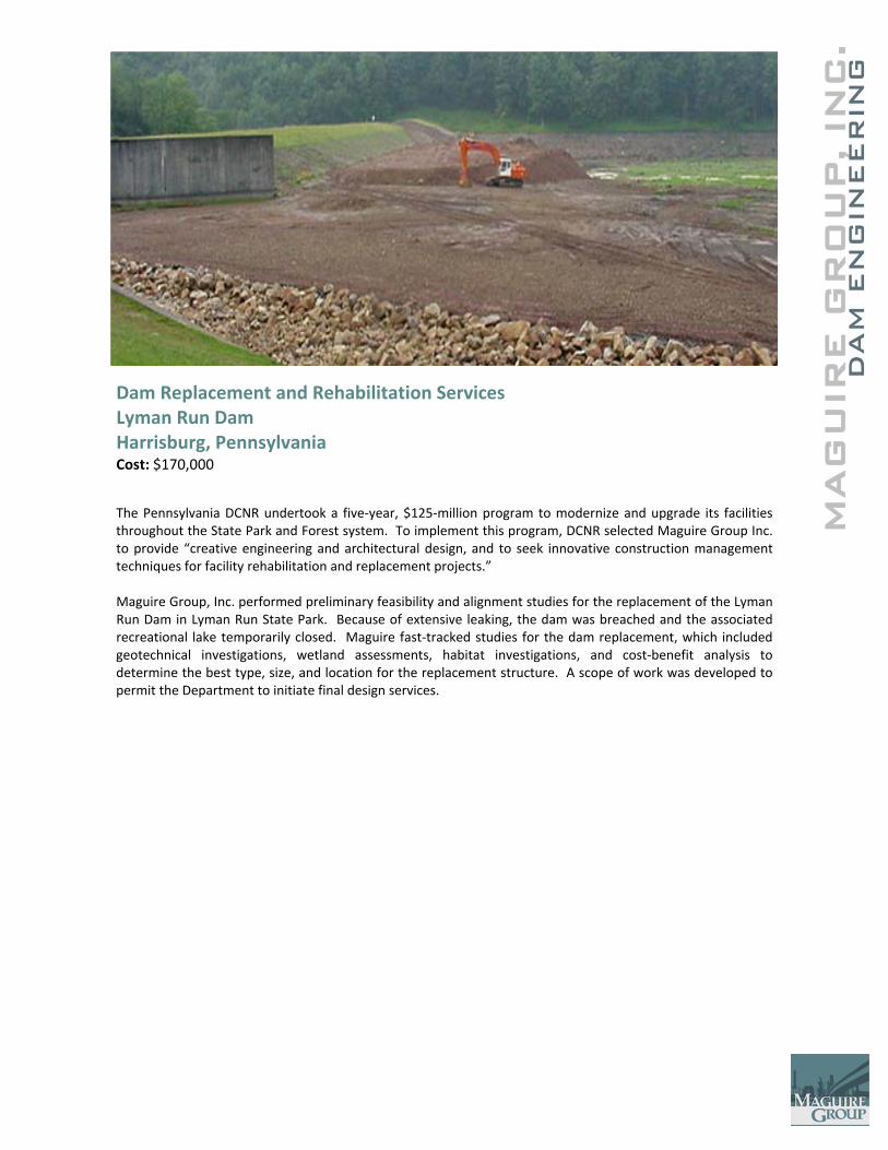
MAG
UIR
E G
RO
UP, IN
DAM
EN
GIN
EER
ING
C
.
Dam Replacement and Rehabilitation Services Lyman Run Dam Harrisburg, Pennsylvania Cost: $170,000
The Pennsylvania DCNR undertook a five‐year, $125‐million program to modernize and upgrade its facilities throughout the State Park and Forest system. To implement this program, DCNR selected Maguire Group Inc. to provide “creative engineering and architectural design, and to seek innovative construction management techniques for facility rehabilitation and replacement projects.” Maguire Group, Inc. performed preliminary feasibility and alignment studies for the replacement of the Lyman Run Dam in Lyman Run State Park. Because of extensive leaking, the dam was breached and the associated recreational lake temporarily closed. Maguire fast‐tracked studies for the dam replacement, which included geotechnical investigations, wetland assessments, habitat investigations, and cost‐benefit analysis to determine the best type, size, and location for the replacement structure. A scope of work was developed to permit the Department to initiate final design services.
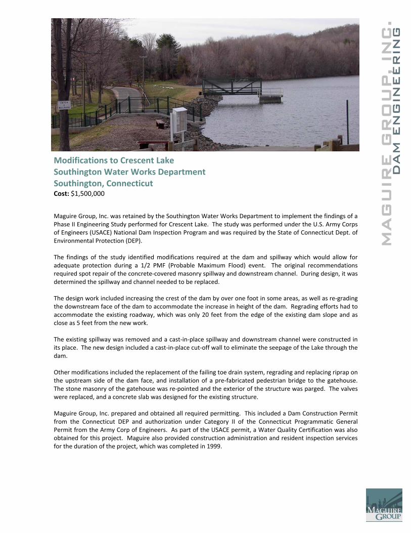
MAG
UIR
E G
RO
UP, IN
DAM
EN
GIN
EER
ING
C
.
Modifications to Crescent Lake Southington Water Works Department Southington, Connecticut Cost: $1,500,000
Maguire Group, Inc. was retained by the Southington Water Works Department to implement the findings of a Phase II Engineering Study performed for Crescent Lake. The study was performed under the U.S. Army Corps of Engineers (USACE) National Dam Inspection Program and was required by the State of Connecticut Dept. of Environmental Protection (DEP). The findings of the study identified modifications required at the dam and spillway which would allow for adequate protection during a 1/2 PMF (Probable Maximum Flood) event. The original recommendations required spot repair of the concrete‐covered masonry spillway and downstream channel. During design, it was determined the spillway and channel needed to be replaced. The design work included increasing the crest of the dam by over one foot in some areas, as well as re‐grading the downstream face of the dam to accommodate the increase in height of the dam. Regrading efforts had to accommodate the existing roadway, which was only 20 feet from the edge of the existing dam slope and as close as 5 feet from the new work. The existing spillway was removed and a cast‐in‐place spillway and downstream channel were constructed in its place. The new design included a cast‐in‐place cut‐off wall to eliminate the seepage of the Lake through the dam. Other modifications included the replacement of the failing toe drain system, regrading and replacing riprap on the upstream side of the dam face, and installation of a pre‐fabricated pedestrian bridge to the gatehouse. The stone masonry of the gatehouse was re‐pointed and the exterior of the structure was parged. The valves were replaced, and a concrete slab was designed for the existing structure. Maguire Group, Inc. prepared and obtained all required permitting. This included a Dam Construction Permit from the Connecticut DEP and authorization under Category II of the Connecticut Programmatic General Permit from the Army Corp of Engineers. As part of the USACE permit, a Water Quality Certification was also obtained for this project. Maguire also provided construction administration and resident inspection services for the duration of the project, which was completed in 1999.

MAG
UIR
E G
RO
UP, IN
DAM
EN
GIN
EER
ING
C
.
Bell Pond and Griswold Pond Structural & Geotechnical Condition Evaluation Wethersfield, Connecticut Cost: $300,000 Year of Completion: 2006 Maguire Group, Inc. was selected by the Town of Wethersfield to conduct an evaluation of the existing Bell Pond and Griswold Pond dams and spillways. The purpose of the evaluation was to identify remedial work required at each site. Maguire Group, Inc. conducted a structural and geotechnical condition evaluation and provided the Town with alternative construction repair options, including preliminary quantity and construction cost estimates. Maguire Group, Inc. also prepared design drawings, technical specifications, and DEP permit applications for the selected construction repair option. Project Features
• Structural assessment
• Geotechnical assessment
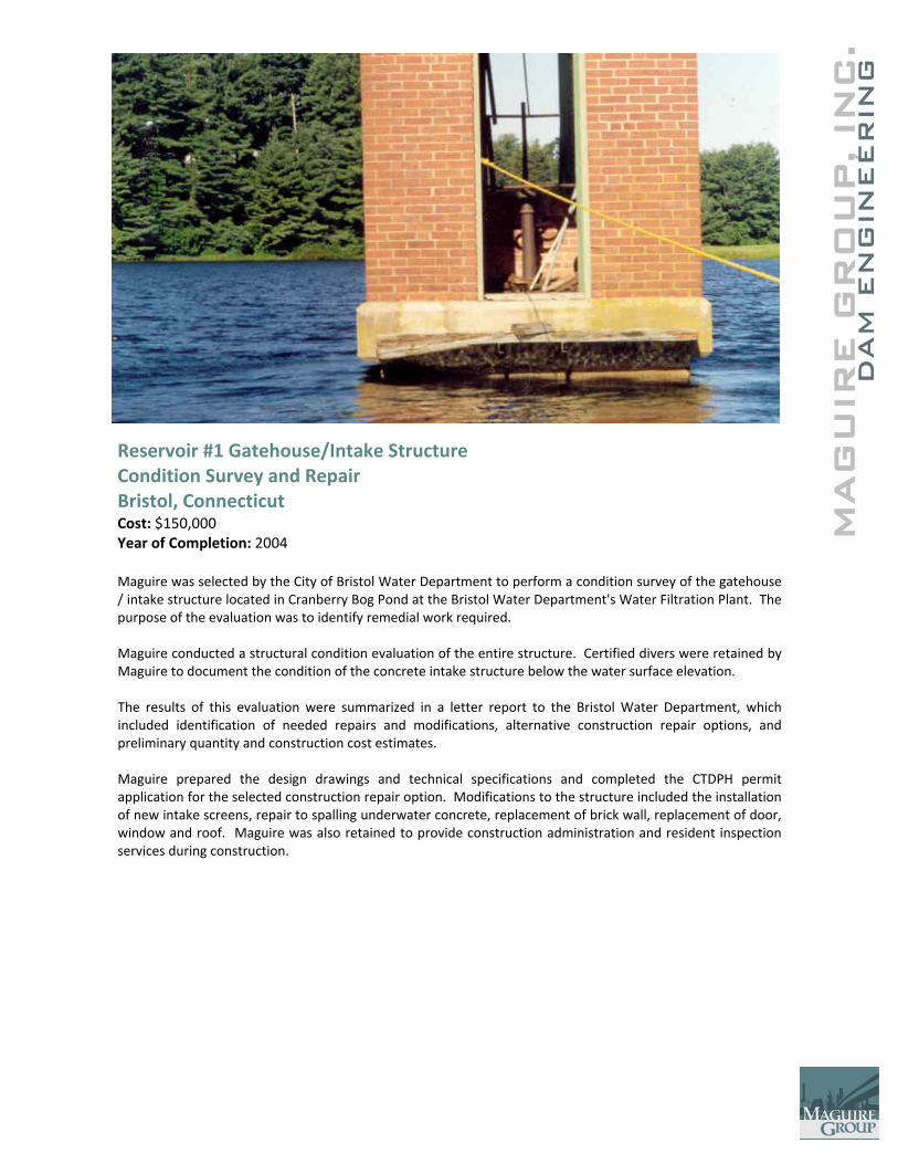
MAG
UIR
E G
RO
UP, IN
DAM
EN
GIN
EER
ING
C
.
Reservoir #1 Gatehouse/Intake Structure Condition Survey and Repair Bristol, Connecticut Cost: $150,000 Year of Completion: 2004 Maguire was selected by the City of Bristol Water Department to perform a condition survey of the gatehouse / intake structure located in Cranberry Bog Pond at the Bristol Water Department's Water Filtration Plant. The purpose of the evaluation was to identify remedial work required. Maguire conducted a structural condition evaluation of the entire structure. Certified divers were retained by Maguire to document the condition of the concrete intake structure below the water surface elevation. The results of this evaluation were summarized in a letter report to the Bristol Water Department, which included identification of needed repairs and modifications, alternative construction repair options, and preliminary quantity and construction cost estimates. Maguire prepared the design drawings and technical specifications and completed the CTDPH permit application for the selected construction repair option. Modifications to the structure included the installation of new intake screens, repair to spalling underwater concrete, replacement of brick wall, replacement of door, window and roof. Maguire was also retained to provide construction administration and resident inspection services during construction.
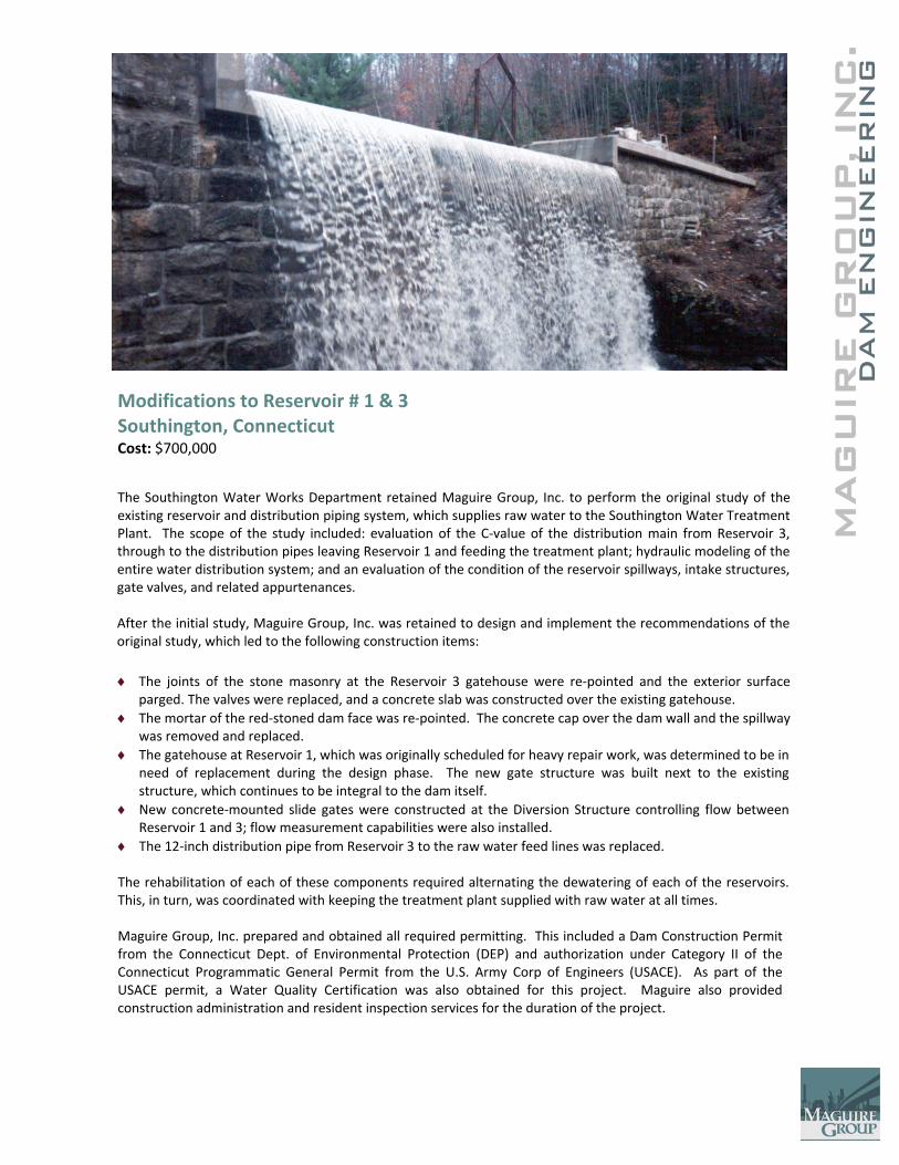
MAG
UIR
E G
RO
UP, IN
DAM
EN
GIN
EER
ING
C
.
Modifications to Reservoir # 1 & 3 Southington, Connecticut Cost: $700,000
The Southington Water Works Department retained Maguire Group, Inc. to perform the original study of the existing reservoir and distribution piping system, which supplies raw water to the Southington Water Treatment Plant. The scope of the study included: evaluation of the C‐value of the distribution main from Reservoir 3, through to the distribution pipes leaving Reservoir 1 and feeding the treatment plant; hydraulic modeling of the entire water distribution system; and an evaluation of the condition of the reservoir spillways, intake structures, gate valves, and related appurtenances. After the initial study, Maguire Group, Inc. was retained to design and implement the recommendations of the original study, which led to the following construction items: ♦ The joints of the stone masonry at the Reservoir 3 gatehouse were re‐pointed and the exterior surface
parged. The valves were replaced, and a concrete slab was constructed over the existing gatehouse. ♦ The mortar of the red‐stoned dam face was re‐pointed. The concrete cap over the dam wall and the spillway
was removed and replaced. ♦ The gatehouse at Reservoir 1, which was originally scheduled for heavy repair work, was determined to be in
need of replacement during the design phase. The new gate structure was built next to the existing structure, which continues to be integral to the dam itself.
♦ New concrete‐mounted slide gates were constructed at the Diversion Structure controlling flow between Reservoir 1 and 3; flow measurement capabilities were also installed.
♦ The 12‐inch distribution pipe from Reservoir 3 to the raw water feed lines was replaced. The rehabilitation of each of these components required alternating the dewatering of each of the reservoirs. This, in turn, was coordinated with keeping the treatment plant supplied with raw water at all times. Maguire Group, Inc. prepared and obtained all required permitting. This included a Dam Construction Permit from the Connecticut Dept. of Environmental Protection (DEP) and authorization under Category II of the Connecticut Programmatic General Permit from the U.S. Army Corp of Engineers (USACE). As part of the USACE permit, a Water Quality Certification was also obtained for this project. Maguire also provided construction administration and resident inspection services for the duration of the project.
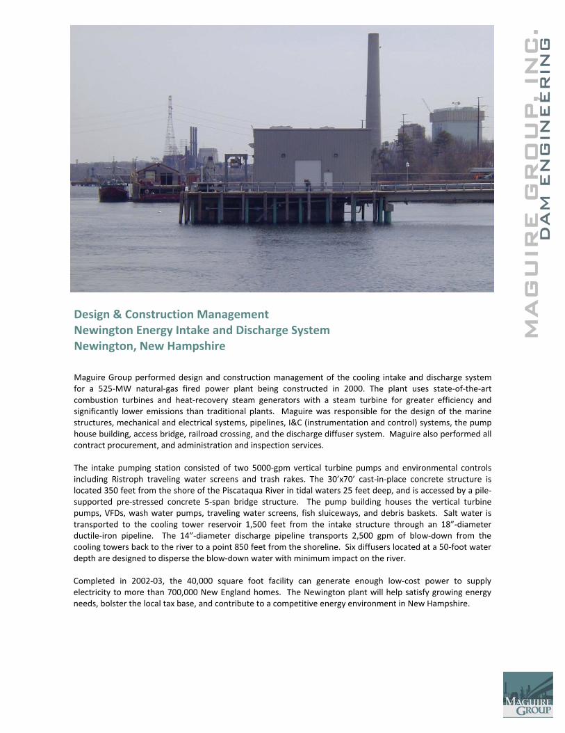
MAG
UIR
E G
RO
UP, IN
DAM
EN
GIN
EER
ING
C
.
Design & Construction Management Newington Energy Intake and Discharge System Newington, New Hampshire
Maguire Group performed design and construction management of the cooling intake and discharge system for a 525‐MW natural‐gas fired power plant being constructed in 2000. The plant uses state‐of‐the‐art combustion turbines and heat‐recovery steam generators with a steam turbine for greater efficiency and significantly lower emissions than traditional plants. Maguire was responsible for the design of the marine structures, mechanical and electrical systems, pipelines, I&C (instrumentation and control) systems, the pump house building, access bridge, railroad crossing, and the discharge diffuser system. Maguire also performed all contract procurement, and administration and inspection services. The intake pumping station consisted of two 5000‐gpm vertical turbine pumps and environmental controls including Ristroph traveling water screens and trash rakes. The 30’x70’ cast‐in‐place concrete structure is located 350 feet from the shore of the Piscataqua River in tidal waters 25 feet deep, and is accessed by a pile‐supported pre‐stressed concrete 5‐span bridge structure. The pump building houses the vertical turbine pumps, VFDs, wash water pumps, traveling water screens, fish sluiceways, and debris baskets. Salt water is transported to the cooling tower reservoir 1,500 feet from the intake structure through an 18”‐diameter ductile‐iron pipeline. The 14”‐diameter discharge pipeline transports 2,500 gpm of blow‐down from the cooling towers back to the river to a point 850 feet from the shoreline. Six diffusers located at a 50‐foot water depth are designed to disperse the blow‐down water with minimum impact on the river. Completed in 2002‐03, the 40,000 square foot facility can generate enough low‐cost power to supply electricity to more than 700,000 New England homes. The Newington plant will help satisfy growing energy needs, bolster the local tax base, and contribute to a competitive energy environment in New Hampshire.