Embed Size (px)
Citation preview
Magnus Technical
News LetterEdition #127 September ‘16
In this IssueQualities of an effective team player
By HR Department
Water Treatment SystemsBy Process Department
Basis for deciding Stress critical lines
By Piping Department
Proper slab construction concepts By Guest Article
HRD QUALITIES OF AN EFFECTIVE TEAM PLAYER
"Work effectively in a team environment" is an
important skill for almost every employee to have. Being
a member of a team means your work is interdependent.
Your ability to do your job is dependent upon others
getting their work done, and others depend on you to
get their work done. Working effectively in a team
environment requires you to communicate well and
often. It demands you to be flexible and that you meet
your deadlines. It's also important for you to recognize
each member of the team for his/her important
contributions.
Here are some of the important features which helps
you to become an Effective Team Player:
COMMUNICATE CONSTRUCTIVELY:
Teams need people who speak up and express their
thoughts and ideas clearly, directly, honestly, and with
respect for others and for the work of the team. That’s
what it means to communicate constructively. Such a
team member does not shy away from making a point
but makes it in the best way possible — in a positive,
confident, and respectful manner. Effective
communication ensures that all team members know
what is required of them. By conducting regular
meetings and sharing information, the project team
manager creates an environment where team members
can demonstrate their individual contributions to the
effort, as well as ask clarifying questions. This minimizes
ambiguity and prevents misunderstandings and conflict.
BE AN ACTIVE PARTICIPANT:
Good team players are active participants. They come
prepared for team meetings and listen and speak up in
discussions. They’re fully engaged in the work of the
team and do not sit passively on the sidelines.
Team members who function as active participants take
the initiative to help make things happen, and they
volunteer for assignments.
DON’T BLAME OTHERS:
People in your group lose respect for you if you're
constantly blaming others for not meeting
deadlines. You're not fooling anyone, people know
who isn't pulling his weight in a group. Pointing the
finger will only make you look cowardly. Group
members understand if you have a heavy workload
and weren't able to meet a deadline. Saying
something like, "I'm really sorry, but I'll get it to you
by the end of today." will earn you a lot more
respect than trying to make it seem like it's
everyone else's fault that you missed your deadline.
GET INVOLVED:
Share suggestions, ideas, solutions and proposals
with your team members. Take the time to help
your fellow teammates, no matter the request.
TIME MANAGEMENT:
Team members depend on each other to complete
tasks according to the plan so that work flows
smoothly from one process or task to the next.
Effective time management involves prioritizing,
scheduling and focusing on work to maintain
productivity. For example, to operate efficiently,
team members should assess each task as important
or urgent. Important activities typically lead to
personal achievement. Urgent activities require
immediate attention and may be associated with
demands from superiors. By categorizing activities,
you can identify distractions and interruptions, and
minimize them in your schedule in the future. This
helps you focus on work that truly contributes to the
overall team’s goal as well as your personal career
objectives.
BE FLEXIBLE:
Teams often deal with changing conditions and
often create changes themselves. Good team
players roll with the punches; they adapt to ever-
changing situations. They don’t complain or get
stressed out because something new is being tried
or some new direction is being set.
Process Water Treatment Systems
Water is a simple compound (H2O), which isindispensable for human health, but when not purified,can harm well beings. These waters have effects not onlyon personal hygiene, but even on industrial levels. To beclean, the water should undergo a number of treatmentsnecessary to make it drinkable, like purifiers to eliminateor reduce pollutants like nitrates, pesticides, heavymetals, organic materials, etc. as well as improvingquality of water by eliminating halides.
Generally treatment plants would follow processesinvolving pre-chlorination to kill germs, addition of alumto coagulate heavy impurities and lime to neutralize thewater, sent to clari-flocculators to remove of settledsludge, followed by filtering overflow water using sandfilters. At this point, water can be re-used at an industriallevel, as boiler feed water (BFW), in utility services, etc.However, this pure water can be made potable bysubjecting to chlorination, resulting in domestic usage.
Let’s discuss about the purificational necessities forindustrial purposes.
Two main processes of industrial water treatment areBoiler Water Treatment and Cooling Water Treatment.Water treatment is necessary to minimize bacterialreactions within pipe work / boiler housing resulting infine-silt like scale deposits which leads to machinery in-efficiency, such as increased fuel consumption whileheating water due to thermal resistance offered by scaleformations. Scales also narrows pipe widths and therebyincreases energy required to pump water through pipes.
Corrosion in low pressure boilers can be caused bydissolved oxygen, acidity and excessive alkalinity.Treatment must remove these to maintain boilerwater with appropriate pH and alkalinity levels.Without effective water treatment, cooling watersystems may suffer from scale formation, corrosionand fouling and may become a breeding ground forharmful bacteria; thereby, shortening plant life andmaking operations unreliable. Corrosion also leadsto leaks, which leads to catastrophic failures, inpressurized systems.
Microbes thrive in untreated cooling waters whichare full of organic nutrients, as found in wet coolingtowers. Dust, flies, grass, fungal spores, and otherscollect in the water and create a sort of "microbialsoup", if not treated with biocides; thereby,stringent Health & Safety guidelines concerningcooling tower operations have been implemented.
Technologies
Advancements in water treatment technology haveaffected all areas of industrial water treatment.Although mechanical filtration, such as reverseosmosis, is widely employed to filter contaminants,there are other technologies that may find betterimplementation as follows:
Ozone Treatment is a process in which ozone gas isinjected into waste streams as a means to reduce oreliminate the need for water treatment chemicals orsanitizers that may be hazardous, including chlorine.
Ultraviolet (UV) Disinfection technology has been acommon water treatment technology in the pasttwo decades due to its ability to provide disinfectedwater without the use of harmful chemicals. The UV-C portion represents wavelengths from 200 nm -280 nm which is used for disinfection, penetratingcells and damaging the nucleic acid, rendering themincapable of reproduction.
Process Water Treatment Systems
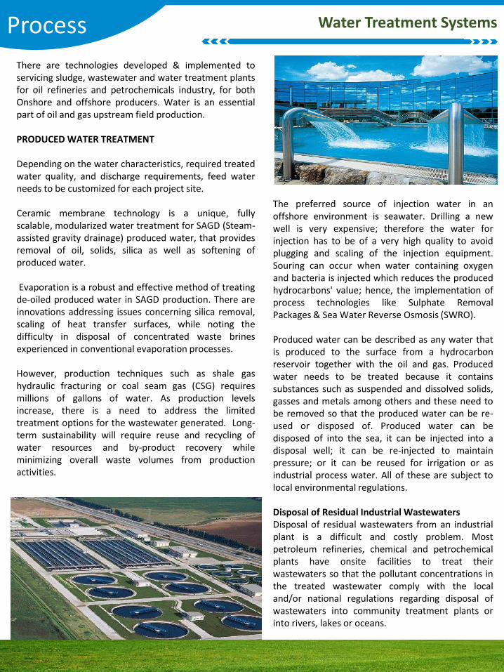
There are technologies developed & implemented toservicing sludge, wastewater and water treatment plantsfor oil refineries and petrochemicals industry, for bothOnshore and offshore producers. Water is an essentialpart of oil and gas upstream field production.
PRODUCED WATER TREATMENT
Depending on the water characteristics, required treatedwater quality, and discharge requirements, feed waterneeds to be customized for each project site.
Ceramic membrane technology is a unique, fullyscalable, modularized water treatment for SAGD (Steam-assisted gravity drainage) produced water, that providesremoval of oil, solids, silica as well as softening ofproduced water.
Evaporation is a robust and effective method of treatingde-oiled produced water in SAGD production. There areinnovations addressing issues concerning silica removal,scaling of heat transfer surfaces, while noting thedifficulty in disposal of concentrated waste brinesexperienced in conventional evaporation processes.
However, production techniques such as shale gashydraulic fracturing or coal seam gas (CSG) requiresmillions of gallons of water. As production levelsincrease, there is a need to address the limitedtreatment options for the wastewater generated. Long-term sustainability will require reuse and recycling ofwater resources and by-product recovery whileminimizing overall waste volumes from productionactivities.
The preferred source of injection water in anoffshore environment is seawater. Drilling a newwell is very expensive; therefore the water forinjection has to be of a very high quality to avoidplugging and scaling of the injection equipment.Souring can occur when water containing oxygenand bacteria is injected which reduces the producedhydrocarbons' value; hence, the implementation ofprocess technologies like Sulphate RemovalPackages & Sea Water Reverse Osmosis (SWRO).
Produced water can be described as any water thatis produced to the surface from a hydrocarbonreservoir together with the oil and gas. Producedwater needs to be treated because it containssubstances such as suspended and dissolved solids,gasses and metals among others and these need tobe removed so that the produced water can be re-used or disposed of. Produced water can bedisposed of into the sea, it can be injected into adisposal well; it can be re-injected to maintainpressure; or it can be reused for irrigation or asindustrial process water. All of these are subject tolocal environmental regulations.
Disposal of Residual Industrial WastewatersDisposal of residual wastewaters from an industrialplant is a difficult and costly problem. Mostpetroleum refineries, chemical and petrochemicalplants have onsite facilities to treat theirwastewaters so that the pollutant concentrations inthe treated wastewater comply with the localand/or national regulations regarding disposal ofwastewaters into community treatment plants orinto rivers, lakes or oceans.
Structural PROPER SLAB CONSTRUCTION CONCEPTS:
A CHALLENGE TO OVERCOME
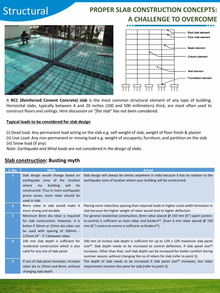
A RCC (Reinforced Cement Concrete) slab is the most common structural element of any type of building.Horizontal slabs, typically between 4 and 20 inches (100 and 500 millimeters) thick, are most often used toconstruct floors and ceilings. Here discussion on “flat slab” has not been considered.
Typical loads to be considered for slab design
(i) Dead load: Any permanent load acting on the slab e.g. self-weight of slab, weight of floor finish & plaster(ii) Live Load: Any non-permanent or moving load e.g. weight of occupants, furniture, and partition on the slab (iii) Snow load (if any)Note: Earthquake and Wind loads are not considered in the design of slabs.
S. No. Myth Actual
1 Slab design would change based on
earthquake zone of the location
where my building will be
constructed. Thus in more earthquake
prone zones, more rebar should be
used in slab.
Slab design will always be similar anywhere in India because it has no relation to the
earthquake zone of location where your building will be constructed.
2 More rebar in slab would make it
more strong and durable.
Placing more rebar/less spacing than required leads to higher crack width formation in
slab because the higher weight of rebar would lead to higher deflection.
3 Minimum 8mm dia rebar is required
for slab construction. However, it is
better if 10mm or 12mm dia rebar can
be used with spacing of 100mm -
125mm (4” - 5’’) between rebar.
For general residential construction, 8mm rebar placed @ 150 mm (6’’) apart (centre-
to-centre) is sufficient as main rebar and binders(a). [Even 6 mm rebar placed @ 150
mm (6’’) centre-to-centre is sufficient as binders(a)]
4 100 mm slab depth is sufficient for
residential construction which is also
valid for any size of slab panel.
100 mm (4 inches) slab depth is sufficient for up to 12ft x 12ft maximum slab panel
size(b). Slab depth needs to be increased to control deflection, if slab panel size(b)
increases. Other than that, roof slab depth can be increased for better comfort during
summer season, without changing the no of rebars for slab (refer to point 3).
5 If size of slab panel increases, increase
rebar dia to 10mm and 8mm, without
changing slab depth.
The depth of slab needs to be increased if slab panel size(b) increases, but rebar
requirement remains the same for slab (refer to point 3).
Slab construction: Busting myth
Structural PROPER SLAB CONSTRUCTION CONCEPTS:
A CHALLENGE TO OVERCOME
6 20mm clear cover in slab is sufficient. 20mm clear cover is sufficient for intermediate floor slabs, and 30mm clear cover
should be provided for roof slab exposed to rain(c).
7 The rebar used in the slab have
resulted in the formation of cracks.
There is no known influence of quality of rebar on the development of cracks in slabs,
unless the rebar is of too inferior strength than required. Factors such as: Building
design not factoring the safe bearing capacity of soil, differential settlement of
footings and wrong design engineering, poor construction practices (such as improper
concrete mix proportioning, higher water-cement ratio, improper compaction,
inadequate curing, improper construction joint treatment) are in general responsible
for the development of cracks in the slabs.
Recommended slab construction practices:
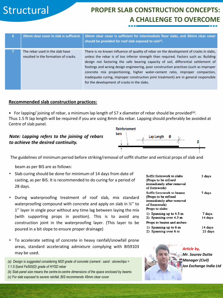
• For lapping/ joining of rebar, a minimum lap length of 57 x diameter of rebar should be provided(a). Thus 1.5 ft lap length will be required if you are using 8mm dia rebar. Lapping should preferably be avoided at Centre of slab panel.
Note: Lapping refers to the joining of rebarsto achieve the desired continuity.
The guidelines of minimum period before striking/removal of soffit shutter and vertical props of slab and
beam as per BIS are as follows:
• Slab curing should be done for minimum of 14 days from date of
casting, as per BIS. It is recommended to do curing for a period of
28 days.
• During waterproofing treatment of roof slab, mix standard
waterproofing compound with concrete and apply on slab in ½’’ to
1’’ layer in single pour without any time lag between laying the mix
(with supporting props in position). This is to avoid any
construction joint in the waterproofing layer. (This layer to be
poured in a bit slope to ensure proper drainage)
• To accelerate setting of concrete in heavy rainfall/snowfall prone
areas, standard accelerating admixture complying with BIS9103
may be used.Article by,
Mr. Sourav Dutta
Manager (Civil)
Ion Exchange India Ltd(a) Design is suggested considering M20 grade of concrete (cement : sand : stonechips =
1:1.5:3)and Fe500(D) grade of HYSD rebar
(b) Slab panel size means the centre-to-centre dimensions of the space enclosed by beams
(c) For slab exposed to severe rainfall, BIS recommends 45mm clear cover
Piping Basis for deciding Stress critical lines
Basis for deciding Stress critical lines:Stress analysis is a complex task and in any process unitthere are a huge number of lines exist which runs fromone location to other. Analyzing all lines will take a lotof time which in turn will increase the engineering timeand corresponding cost. So every engineeringorganization in this field has set up some guidelines fordeciding which lines are to be stress analysed usingsoftware (Caesar II, Auto pipe, Caepipe or Rohr II).
The main factors which decide stress critical lines areas follows:
• Line design/operating/upset temperature• Equipment connection• Pipe and Equipment material• Pipe condition• Pipe thickness• Design/Upset pressure
Every organization has their own guidelines and theguidelines vary from project to project. The followingwrite up will provide few criteria for deciding stresscritical lines. This is only a idea of how thedifferentiation occurs. User are requested to checkproject specific documents for use in any project.
Mostly the critical lines for which stress analysis is tobe performed by formal computer analysis consists ofthe following lines:
• All Pump (Centrifugal-API/ANSI, gear pump, Screwpump) suction and discharge piping (4 inch and larger).• Centrifugal Compressor inlet and outlet piping.• Lines to and from steam generators.• Reciprocating pump and compressor suction anddischarge piping.• Piping requiring expansion joints or other proprietaryexpansion devices.• Steam and Gas Turbine inlet and outlet piping.• Air Cooler inlet and outlet piping (3 inch and larger).• Process Heater inlet and outlet piping• Lines classified as category M as per ASME B31.3.• Piping subjected to high cyclic temperatureconditions.• All jacketed lines.
• Lines that require nozzle load compliance asstipulated per applicable codes or equipmentVendor allowable (Heat exchanger, Pressure VesselConnected systems).• Lines subject to dynamic loading (relief lines, linewith large pressure drop at control valves, surgepressure, slug flow, churn, two phase flow, waterhammer, flashing, etc.)• All Fiberglass, aluminium alloy, refractory orelastomer lined piping.• All piping systems connected to FRP, plastic, glasslined steel or brittle equipment• Lines subjected to non-thermal movements(Expected differential settlement betweenstructures, structure-equipment, etc., processequipment growth, header growth, tower growth orother significant displacements, etc.)• All lines 8” and larger operating above 150 deg. C(300 deg. F) and greater.• All lines 20” and larger operating above 80 deg. C(200 deg. F) and greater.• All lines 36” and larger.• All lines operating below -45 deg. C (-50 deg. F)which require special “cold” supports.• All plastic lined piping systems. Special attentionshall be given to add enough additional supports tolimit the external forces and moments in the flangeconnections to avoid an extra risk of flange leaks• Lines with special design requirements• All Safety pressure relieving systems 4 inch andlarger (not including thermal reliefs)

FOCUS :Magnus Technical News Letter is a unique attempt fromMagnus Group to create a platform for engineers ofdifferent streams to understand concurrent technologiesand know real time challenges faced, along with possiblesolutions.
It gives us immense pleasure to inform you’ll that we willbe publishing the news letter at least once a month. Wewould like to thank the engineering departments for theenthusiasm shown in sharing technology.
YOU CAN BE A PART OF THE TEAM :We welcome you to be a part of this technical movementby sending us your articles or write-up with respect totechnical challenges faced with possible solutions.Please note that your article will be published under yourname after verification of the Article.
Corporate Office : Magnus Global Tech Private Limited#874, Raineo House, 1st Floor, Modi Hospital Road, Basaveshwaranagar, Bengaluru -560086.
Ph No: 91-80-42042954, Email : [email protected]
Scheduled Events
Magnus Global Tech Group
Corporate websitewww.magnus-global.com
Education www.edu.magnus-global.com
Job Portalwww.magnuscorejobs.com
Plant Engineering www.ong.magnus-global.com
MAGNUS CAREER ORIENTATION PROGRAMME – 2016
Magnus Career OrientationProgramme' is a technical,informative and educationalseminar to young engineers.Magnus Global Tech Education -the educational wing of MagnusGroup is organizing MCOP 2016to create an awareness withrespect to industrial expectationand preparation required to besuccessful in getting the desiredjobs.We have conducted MCOP 2016in following colleges to helpcandidates by creatingawareness about core industries.
1. Kongu Engineering College –ERODE
2. St. Joseph Engineering College- Mangaluru.
Please visit expo.magnus-global.com
for further information.


![VARIO Magnus [e]Magnus](https://img.pdfslide.us/doc/110x75/62e7b22695cddb648811f746/vario-magnus-emagnus.jpg)