Embed Size (px)
Citation preview

R.P.S. Corporation Phone: 1-800-450-9824P.O. Box 241 Fax: 1-866-632-6961Racine, Wisconsin 53401
MAGNUMOperator Manual
MA
GN
UM
SE
RIE
S
Version 4.002/19/08
This manual contains the following sections:
- HOW TO USE THIS MANUAL - SAFETY - OPERATIONS - MAINTENANCE - PARTS LIST
The HOW TO USE THIS MANUAL section willtell you how to find important informationfor ordering the correct replacement parts.
Parts may be ordered from authorized dealers.When placing an order for parts, the machinemodel and serial number are important.
Refer to MACHINE INFORMATION on page oneof this manual, which is filled out during theinstallation of your machine.
The serial number of your machine is locatedon the lower half of the control panel of themachine. (See Picture Below)
The SAFETY section contains important informationregarding hazard or unsafe practices of themachine.
Levels of hazards are identified that could resultin product or personal injury, or severe injuryresulting in death.
The OPERATIONS section is to familiarize theoperator with the operation and function of themachine.
The MAINTENANCE section contains preventativemaintenance to keep the machine and itscomponents in good working condition. They arelisted in this general order:
- Batteries - Scrub Brushes - Adjusting Squeegee - Service Schedule - Machine Trouble Shooting
The PARTS LIST section contains assembled partsillustrations and corresponding parts list. The partslists include a number of columns of information:
- ITEM - Column refers to the reference number on the parts illustration.
- PART NO. - Column lists the part number for the part.
- QTY - Column lists the quantity of the part used in that area of the machine.
- DESCRIPTION - Column is a brief description of the part.
- COMMENTS - Column for information not noted by the other columns.
NOTE: If a service or option kit is installed on yourmachine, be sure to keep the KIT INSTRUCTIONSwhich came with the kit. It contains replacementpart numbers needed for ordering future parts.
HOW TO USE THIS MANUAL
As our policy is one of constant improvement, all informationand specifications are subject to change without notice. **
Serial Number
MACHINE INFORMATION FORMWARRANTY REGISTRATION FORMMACHINE SPECIFICATIONSCOMMON WEAR PARTSSAFETY MESSAGES!!SAFETY PRECAUTIONS!!MACHINE CONTROLS AND FEATURESMACHINE SETUPADJUSTING & REMOVING SQUEEGEEINSTALLING PAD DRIVER OR BRUSHINSTALLING CYLINDRICAL BRUSHESSIDE BROOM SYSTEMOPERATIONADJ. SOLUTION FLOW & CURTAINS, DRAINING TANKSCLEANING RECOVERY TANKTIP TANK, RAISE & LOWER SQUEEGEEADJUST DECK HEIGHT, VAC MOTOR & SOLUTION FILTERCHARGING BATTERIESON-BOARD BATTERY CHARGER "OPTIONAL"MAINTENANCE & STORING MACHINEPREVENTATIVE MAINTENANCE RECORDSLCD SCREEN MENU DISPLAY'STROUBLESHOOTING
PAGE 1PAGE 2PAGE 3PAGE 4PAGE 5PAGE 6PAGE 7-8PAGE 9PAGE 10PAGE 11PAGE 12PAGE 13PAGE 14-15PAGE 16PAGE 17PAGE 18PAGE 19PAGE 20PAGE 21-26PAGE 27PAGE 28-29PAGE 30PAGE 31-36
TABLE OF CONTENTS
PAGE 1
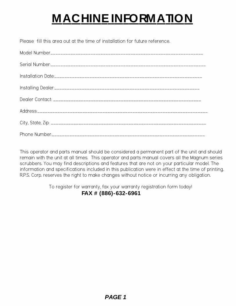
MACHINE INFORMATIONPlease fill this area out at the time of installation for future reference.
Model Number_____________________________________________________________
Serial Number:______________________________________________________________
Installation Date:___________________________________________________________
Installing Dealer:__________________________________________________________
Dealer Contact: ___________________________________________________________
Address:____________________________________________________________________
City, State, Zip: ______________________________________________________________
Phone Number:_____________________________________________________________
This operator and parts manual should be considered a permanent part of the unit and shouldremain with the unit at all times. This operator and parts manual covers all the Magnum seriesscrubbers. You may find descriptions and features that are not on your particular model. Theinformation and specifications included in this publication were in effect at the time of printing.R.P.S. Corp. reserves the right to make changes without notice or incurring any obligation.
To register for warranty, fax your warranty registration form today!FAX # (886)-632-6961
R.P.S. CORPORATIONP.O. BOX 368RACINE, WI 53401PHONE: 800-634-4060
PAGE 2
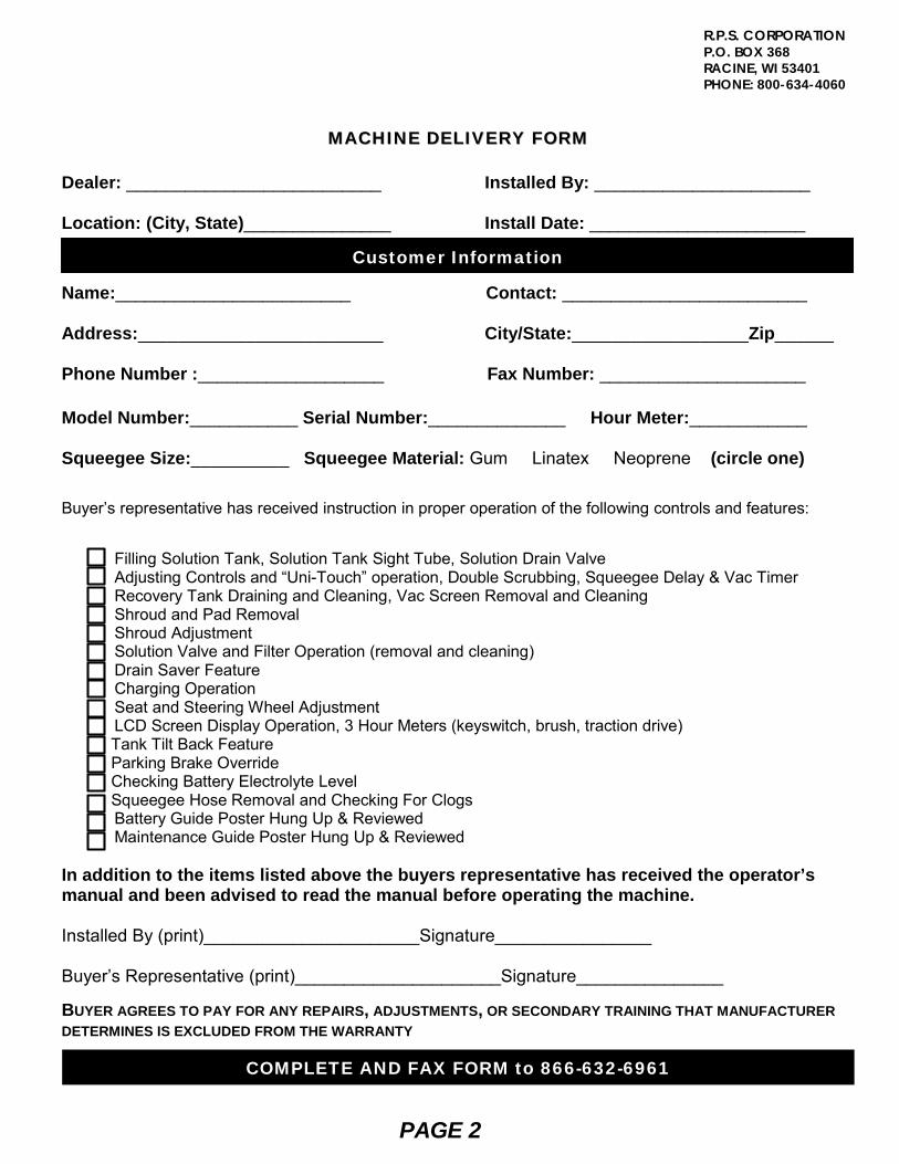
MMAACCHHIINNEE DDEELLIIVVEERRYY FFOORRMM
Dealer: __________________________ Installed By: ______________________ Location: (City, State)_______________ Install Date: ______________________ Name:________________________ Contact: _________________________ Address:_________________________ City/State:__________________Zip______ Phone Number :___________________ Fax Number: _____________________ Model Number:___________ Serial Number:______________ Hour Meter:____________ Squeegee Size:__________ Squeegee Material: Gum Linatex Neoprene (circle one)
Buyer’s representative has received instruction in proper operation of the following controls and features:
Filling Solution Tank, Solution Tank Sight Tube, Solution Drain Valve Adjusting Controls and “Uni-Touch” operation, Double Scrubbing, Squeegee Delay & Vac Timer Recovery Tank Draining and Cleaning, Vac Screen Removal and Cleaning Shroud and Pad Removal Shroud Adjustment Solution Valve and Filter Operation (removal and cleaning) Drain Saver Feature Charging Operation Seat and Steering Wheel Adjustment LCD Screen Display Operation, 3 Hour Meters (keyswitch, brush, traction drive) Tank Tilt Back Feature Parking Brake Override Checking Battery Electrolyte Level Squeegee Hose Removal and Checking For Clogs Battery Guide Poster Hung Up & Reviewed Maintenance Guide Poster Hung Up & Reviewed In addition to the items listed above the buyers representative has received the operator’s manual and been advised to read the manual before operating the machine. Installed By (print)______________________Signature________________ Buyer’s Representative (print)_____________________Signature_______________ BUYER AGREES TO PAY FOR ANY REPAIRS, ADJUSTMENTS, OR SECONDARY TRAINING THAT MANUFACTURER DETERMINES IS EXCLUDED FROM THE WARRANTY COMPLETE AND FAX FORM to 866-632-6961
Customer Information
PAGE 3
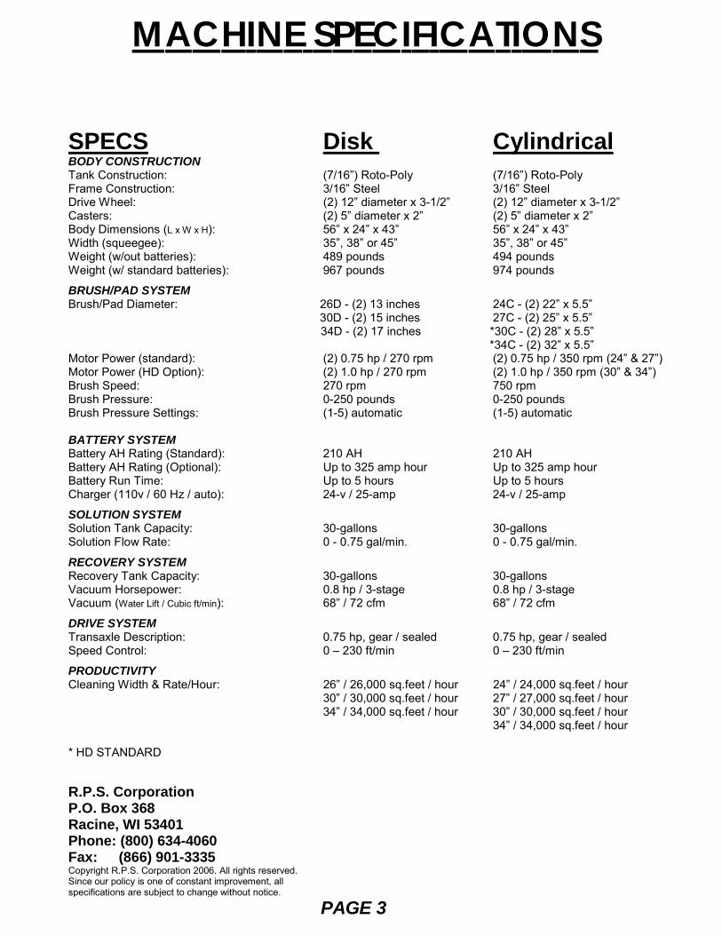
SPECS Disk Cylindrical BODY CONSTRUCTION Tank Construction: (7/16”) Roto-Poly (7/16”) Roto-Poly Frame Construction: 3/16” Steel 3/16” Steel Drive Wheel: (2) 12” diameter x 3-1/2” (2) 12” diameter x 3-1/2” Casters: (2) 5” diameter x 2” (2) 5” diameter x 2” Body Dimensions (L x W x H): 56” x 24” x 43” 56” x 24” x 43” Width (squeegee): 35”, 38” or 45” 35”, 38” or 45” Weight (w/out batteries): 489 pounds 494 pounds Weight (w/ standard batteries): 967 pounds 974 pounds
BRUSH/PAD SYSTEM Brush/Pad Diameter: 26D - (2) 13 inches 24C - (2) 22” x 5.5” 30D - (2) 15 inches 27C - (2) 25” x 5.5” 34D - (2) 17 inches *30C - (2) 28” x 5.5”
*34C - (2) 32” x 5.5” Motor Power (standard): (2) 0.75 hp / 270 rpm (2) 0.75 hp / 350 rpm (24” & 27”)Motor Power (HD Option): (2) 1.0 hp / 270 rpm (2) 1.0 hp / 350 rpm (30” & 34”) Brush Speed: 270 rpm 750 rpm Brush Pressure: 0-250 pounds 0-250 pounds Brush Pressure Settings: (1-5) automatic (1-5) automatic
BATTERY SYSTEM Battery AH Rating (Standard): 210 AH 210 AH Battery AH Rating (Optional): Up to 325 amp hour Up to 325 amp hour Battery Run Time: Up to 5 hours Up to 5 hours Charger (110v / 60 Hz / auto): 24-v / 25-amp 24-v / 25-amp
SOLUTION SYSTEM Solution Tank Capacity: 30-gallons 30-gallons Solution Flow Rate: 0 - 0.75 gal/min. 0 - 0.75 gal/min.
RECOVERY SYSTEM Recovery Tank Capacity: 30-gallons 30-gallons Vacuum Horsepower: 0.8 hp / 3-stage 0.8 hp / 3-stage Vacuum (Water Lift / Cubic ft/min): 68” / 72 cfm 68” / 72 cfm
DRIVE SYSTEM Transaxle Description: 0.75 hp, gear / sealed 0.75 hp, gear / sealed Speed Control: 0 – 230 ft/min 0 – 230 ft/min
PRODUCTIVITY Cleaning Width & Rate/Hour: 26” / 26,000 sq.feet / hour 24” / 24,000 sq.feet / hour
30” / 30,000 sq.feet / hour 27” / 27,000 sq.feet / hour 34” / 34,000 sq.feet / hour 30” / 30,000 sq.feet / hour
34” / 34,000 sq.feet / hour
* HD STANDARD R.P.S. Corporation P.O. Box 368 Racine, WI 53401 Phone: (800) 634-4060 Fax: (866) 901-3335 Copyright R.P.S. Corporation 2006. All rights reserved. Since our policy is one of constant improvement, all specifications are subject to change without notice.
MACHINE SPECIFICATIONS

COMMON WEAR PARTS
PAGE 4
MODEL24"-CYL
N/A 225-821S 225-821C 225-821PS N/A 225-821N
MODEL34"-DISK 17-421SS 17-421S 17-421C 17-421PS 17-421P 17-421N 17-421T 17-421D 17-421DD
MODEL30"-DISK
15-421SS 15-421S 15-421C 15-421PS 15-421P 15-421N 15-421T 15-421D 15-421DD
MODEL26"-DISK
13-421SS 13-421S 13-421C 13-421PS 13-421P 13-421N 13-421T 13-421D 13-421DD
MODEL27"-CYL
N/A 255-821S 255-821C 255-821PS N/A 255-821N
MODEL30"-CYL
N/A 285-821S 285-821C 285-821PS N/A 285-821N
MODEL34"-CYL
N/A 325-821S 325-821C 325-821PS N/A 325-821N
BRUSHESSUPER-GRIT
TOUGH-GRITMIDI-GRITLIGHT-GRITPOLY (.028)
NYLON (.016)TAMPICO
PAD DRIVERDIAMOND DRIVER
SQUEEGEE SIZE'S32" SQUEEGEE "OPTIONAL".35" SQUEEGEE "STANDARD" ON 24", 26" & 27" MACHINES.38" SQUEEGEE "STANDARD" ON 30" MACHINES.45" SQUEEGEE "STANDARD" ON 34" MACHINES.
GUM RUBBER22-770G25-770G28-770G290-770G
LINATEX22-770L25-770L28-770L
290-770L
SQUEEGEE KITS INCLUDE: (1) Rear Blade, (1) Front Blade, and (2) Backup Wheels with harware.
NOTE: Size is stamped into the top of the painted steel squeegee body on all squeegee's.
NOTE: The squeegee is designed for narrow isles and may not have the same water control around tight turns as the larger squeegees.
EXTRA PAD DRIVER RETAINING CLIP: 40-433BRUSH REPAIR KIT: 40-423 REPLACEMENT LOCATING CLIP FOR ALL DISK BRUSHES.
NEW STYLE CYL BRUSHES FOR MACHINE SERIAL #50000 & GREATER
OLD STYLE CYL BRUSHES FOR MACHINES PRIOR TO SERIAL #50000
BRUSHESSUPER-GRIT
TOUGH-GRITMIDI-GRITLIGHT-GRITPOLY (.028)
NYLON (.016)
BRUSHESSUPER-GRIT
TOUGH-GRITMIDI-GRITLIGHT-GRITPOLY (.028)
NYLON (.016)TAMPICO
MODEL24"-CYL
N/A 22-521S 22-521C 22-521PS N/A 22-521N N/A
MODEL27"-CYL
N/A 25-521S 25-521C 25-521PS N/A 25-521N N/A
MODEL30"-CYL
N/A 28-521S 28-521C 28-521PS N/A 28-521N N/A
MODEL34"-CYL
N/A 32-521S 32-521C 32-521PS N/A 32-521N N/A
NOTE: Squeegee Assemblies (complete) listed below all come with Linatex blades.
SIZE P/N 32" 23-7180 35" 25-7180 38" 28-7180 45" 290-7180
PADSSUPER BLACK
BLACKBROWNGREENBLUERED
WHITE
LEVELVERY HIGH
HIGHHIGH
MEDIUMMODERATEMODERATE
LIGHT
COLORBLACKBLACK
BROWNGREENBLUERED
WHITE
SOAPHeavy Duty DegreaserCitrusFreezerTire Mark RemoverFor more soap information call PowerCat 414-745-9337www.powercatsolutions.com
DISK##422BB##422B##422BR##422G##422BL##422R##422W
NOTE: # In Disk Column Denotes Pad Size: 13,15, 17
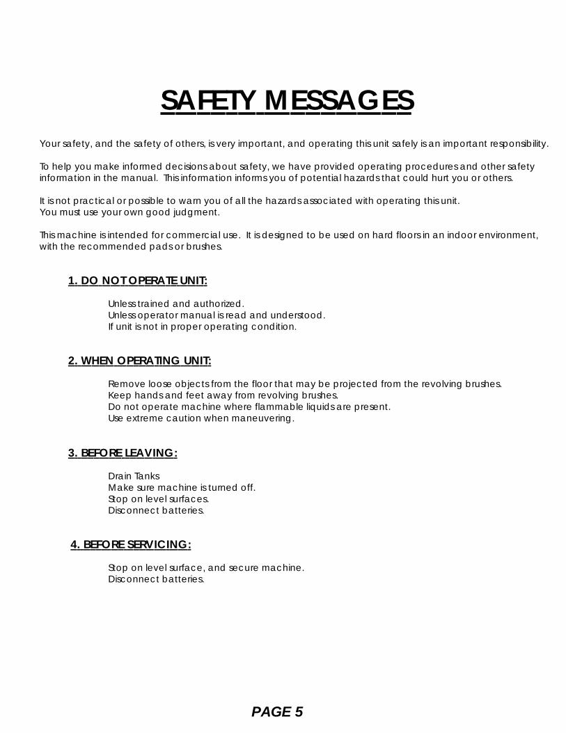
SAFETY MESSAGESYour safety, and the safety of others, is very important, and operating this unit safely is an important responsibility.
To help you make informed decisions about safety, we have provided operating procedures and other safetyinformation in the manual. This information informs you of potential hazards that could hurt you or others.
It is not practical or possible to warn you of all the hazards associated with operating this unit.You must use your own good judgment.
This machine is intended for commercial use. It is designed to be used on hard floors in an indoor environment,with the recommended pads or brushes.
1. DO NOT OPERATE UNIT:
Unless trained and authorized. Unless operator manual is read and understood. If unit is not in proper operating condition.
2. WHEN OPERATING UNIT:
Remove loose objects from the floor that may be projected from the revolving brushes. Keep hands and feet away from revolving brushes. Do not operate machine where flammable liquids are present. Use extreme caution when maneuvering.
3. BEFORE LEAVING:
Drain Tanks Make sure machine is turned off. Stop on level surfaces. Disconnect batteries.
4. BEFORE SERVICING:
Stop on level surface, and secure machine. Disconnect batteries.
PAGE 5
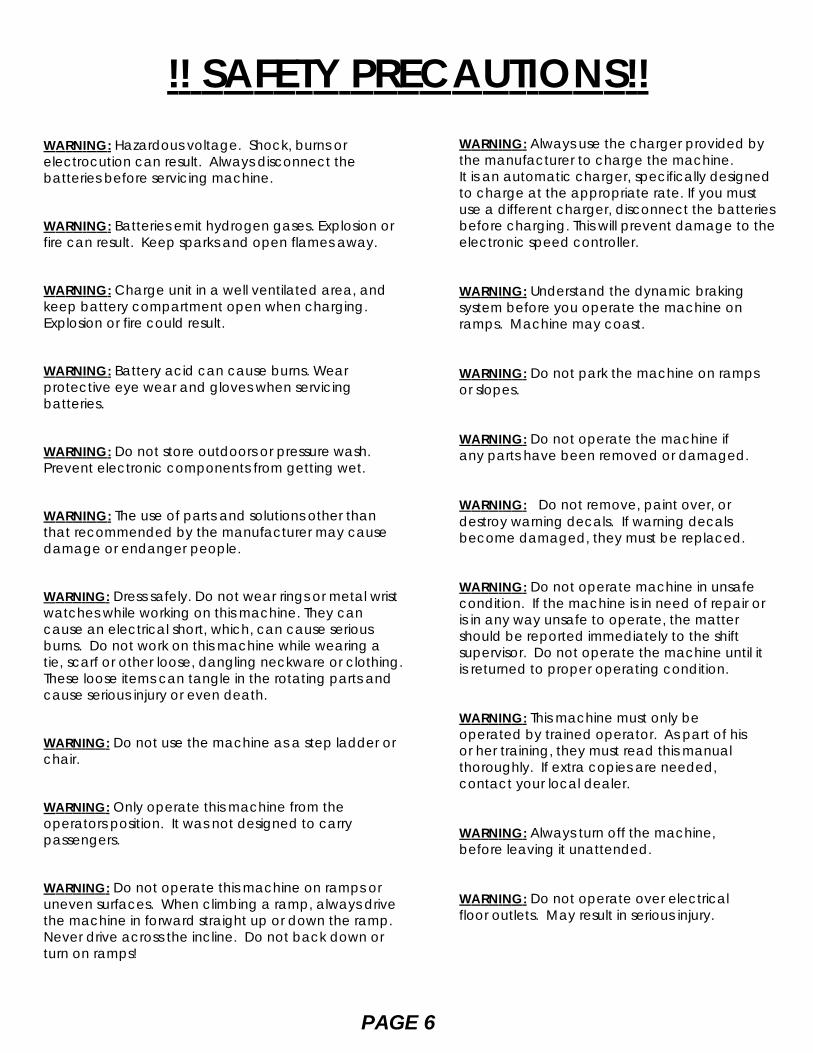
!! SAFETY PRECAUTIONS!!WARNING: Always use the charger provided bythe manufacturer to charge the machine.It is an automatic charger, specifically designedto charge at the appropriate rate. If you mustuse a different charger, disconnect the batteriesbefore charging. This will prevent damage to theelectronic speed controller.
WARNING: Understand the dynamic brakingsystem before you operate the machine onramps. Machine may coast.
WARNING: Do not park the machine on rampsor slopes.
WARNING: Do not operate the machine ifany parts have been removed or damaged.
WARNING: Do not remove, paint over, ordestroy warning decals. If warning decalsbecome damaged, they must be replaced.
WARNING: Do not operate machine in unsafecondition. If the machine is in need of repair oris in any way unsafe to operate, the mattershould be reported immediately to the shiftsupervisor. Do not operate the machine until itis returned to proper operating condition.
WARNING: This machine must only beoperated by trained operator. As part of hisor her training, they must read this manualthoroughly. If extra copies are needed,contact your local dealer.
WARNING: Always turn off the machine,before leaving it unattended.
WARNING: Do not operate over electricalfloor outlets. May result in serious injury.
PAGE 6
WARNING: Hazardous voltage. Shock, burns orelectrocution can result. Always disconnect thebatteries before servicing machine.
WARNING: Batteries emit hydrogen gases. Explosion orfire can result. Keep sparks and open flames away.
WARNING: Charge unit in a well ventilated area, andkeep battery compartment open when charging.Explosion or fire could result.
WARNING: Battery acid can cause burns. Wearprotective eye wear and gloves when servicingbatteries.
WARNING: Do not store outdoors or pressure wash.Prevent electronic components from getting wet.
WARNING: The use of parts and solutions other thanthat recommended by the manufacturer may causedamage or endanger people.
WARNING: Dress safely. Do not wear rings or metal wristwatches while working on this machine. They cancause an electrical short, which, can cause seriousburns. Do not work on this machine while wearing atie, scarf or other loose, dangling neckware or clothing.These loose items can tangle in the rotating parts andcause serious injury or even death.
WARNING: Do not use the machine as a step ladder orchair.
WARNING: Only operate this machine from theoperators position. It was not designed to carrypassengers.
WARNING: Do not operate this machine on ramps oruneven surfaces. When climbing a ramp, always drivethe machine in forward straight up or down the ramp.Never drive across the incline. Do not back down orturn on ramps!
PAGE 7
FIGURE 1.
MACHINE CONTROLS AND FEATURES1
2 3
4 5
6 7 8
24
31
25
29
28
23
30
26
27
32
33
34
393538
40
20
FIGURE 3.
FIGURE 4A.FIGURE 4B.
21 22
3637
41
9
10
11
12
13
14
1515
19
17
18
FIGURE 2.
PAGE 8
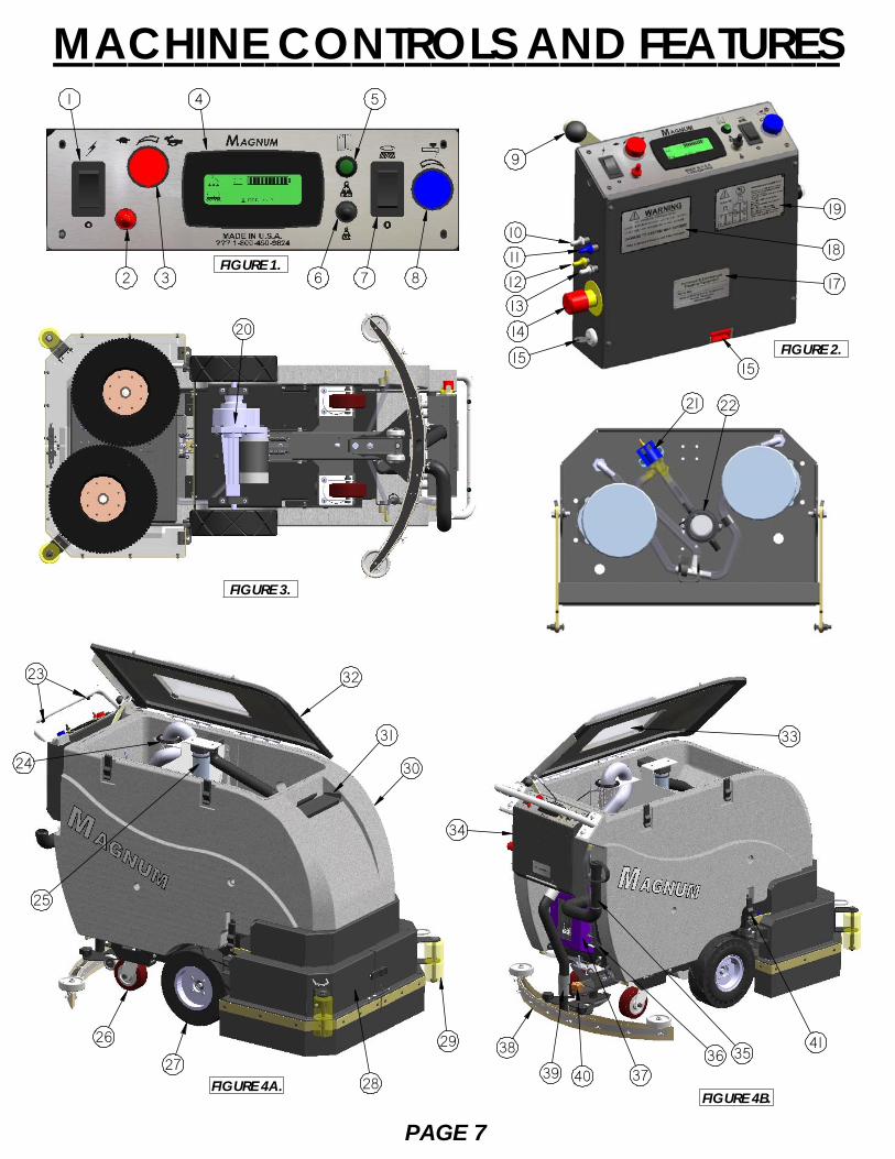
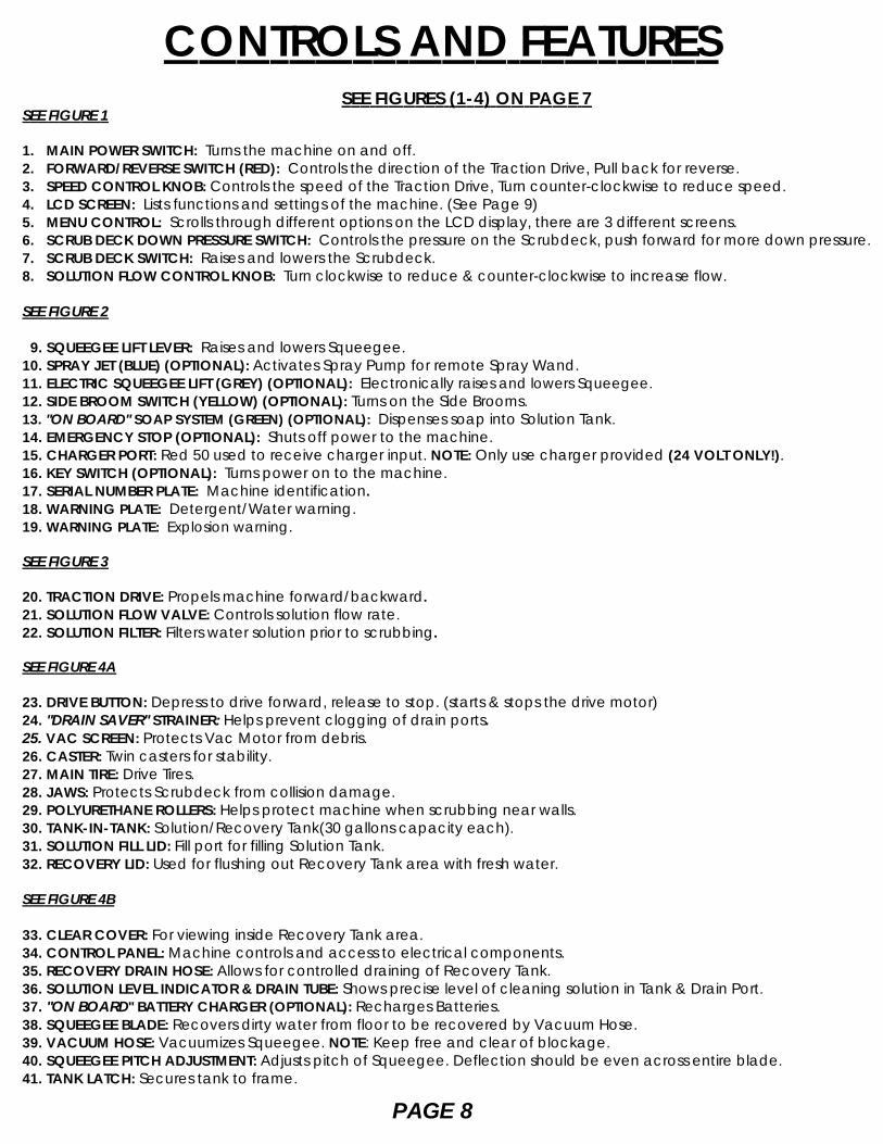
CONTROLS AND FEATURESSEE FIGURES (1-4) ON PAGE 7
SEE FIGURE 1
1. MAIN POWER SWITCH: Turns the machine on and off.2. FORWARD/REVERSE SWITCH (RED): Controls the direction of the Traction Drive, Pull back for reverse.3. SPEED CONTROL KNOB: Controls the speed of the Traction Drive, Turn counter-clockwise to reduce speed.4. LCD SCREEN: Lists functions and settings of the machine. (See Page 9)5. MENU CONTROL: Scrolls through different options on the LCD display, there are 3 different screens.6. SCRUB DECK DOWN PRESSURE SWITCH: Controls the pressure on the Scrubdeck, push forward for more down pressure.7. SCRUB DECK SWITCH: Raises and lowers the Scrubdeck.8. SOLUTION FLOW CONTROL KNOB: Turn clockwise to reduce & counter-clockwise to increase flow.
SEE FIGURE 2
9. SQUEEGEE LIFT LEVER: Raises and lowers Squeegee.10. SPRAY JET (BLUE) (OPTIONAL): Activates Spray Pump for remote Spray Wand.11. ELECTRIC SQUEEGEE LIFT (GREY) (OPTIONAL): Electronically raises and lowers Squeegee.12. SIDE BROOM SWITCH (YELLOW) (OPTIONAL): Turns on the Side Brooms.13. "ON BOARD" SOAP SYSTEM (GREEN) (OPTIONAL): Dispenses soap into Solution Tank.14. EMERGENCY STOP (OPTIONAL): Shuts off power to the machine.15. CHARGER PORT: Red 50 used to receive charger input. NOTE: Only use charger provided (24 VOLT ONLY!).16. KEY SWITCH (OPTIONAL): Turns power on to the machine.17. SERIAL NUMBER PLATE: Machine identification.18. WARNING PLATE: Detergent/Water warning.19. WARNING PLATE: Explosion warning.
SEE FIGURE 3
20. TRACTION DRIVE: Propels machine forward/backward.21. SOLUTION FLOW VALVE: Controls solution flow rate.22. SOLUTION FILTER: Filters water solution prior to scrubbing.
SEE FIGURE 4A
23. DRIVE BUTTON: Depress to drive forward, release to stop. (starts & stops the drive motor)24. "DRAIN SAVER" STRAINER: Helps prevent clogging of drain ports.25. VAC SCREEN: Protects Vac Motor from debris.26. CASTER: Twin casters for stability.27. MAIN TIRE: Drive Tires.28. JAWS: Protects Scrubdeck from collision damage.29. POLYURETHANE ROLLERS: Helps protect machine when scrubbing near walls.30. TANK-IN-TANK: Solution/Recovery Tank(30 gallons capacity each).31. SOLUTION FILL LID: Fill port for filling Solution Tank.32. RECOVERY LID: Used for flushing out Recovery Tank area with fresh water.
SEE FIGURE 4B
33. CLEAR COVER: For viewing inside Recovery Tank area.34. CONTROL PANEL: Machine controls and access to electrical components.35. RECOVERY DRAIN HOSE: Allows for controlled draining of Recovery Tank.36. SOLUTION LEVEL INDICATOR & DRAIN TUBE: Shows precise level of cleaning solution in Tank & Drain Port.37. "ON BOARD" BATTERY CHARGER (OPTIONAL): Recharges Batteries.38. SQUEEGEE BLADE: Recovers dirty water from floor to be recovered by Vacuum Hose.39. VACUUM HOSE: Vacuumizes Squeegee. NOTE: Keep free and clear of blockage.40. SQUEEGEE PITCH ADJUSTMENT: Adjusts pitch of Squeegee. Deflection should be even across entire blade.41. TANK LATCH: Secures tank to frame.
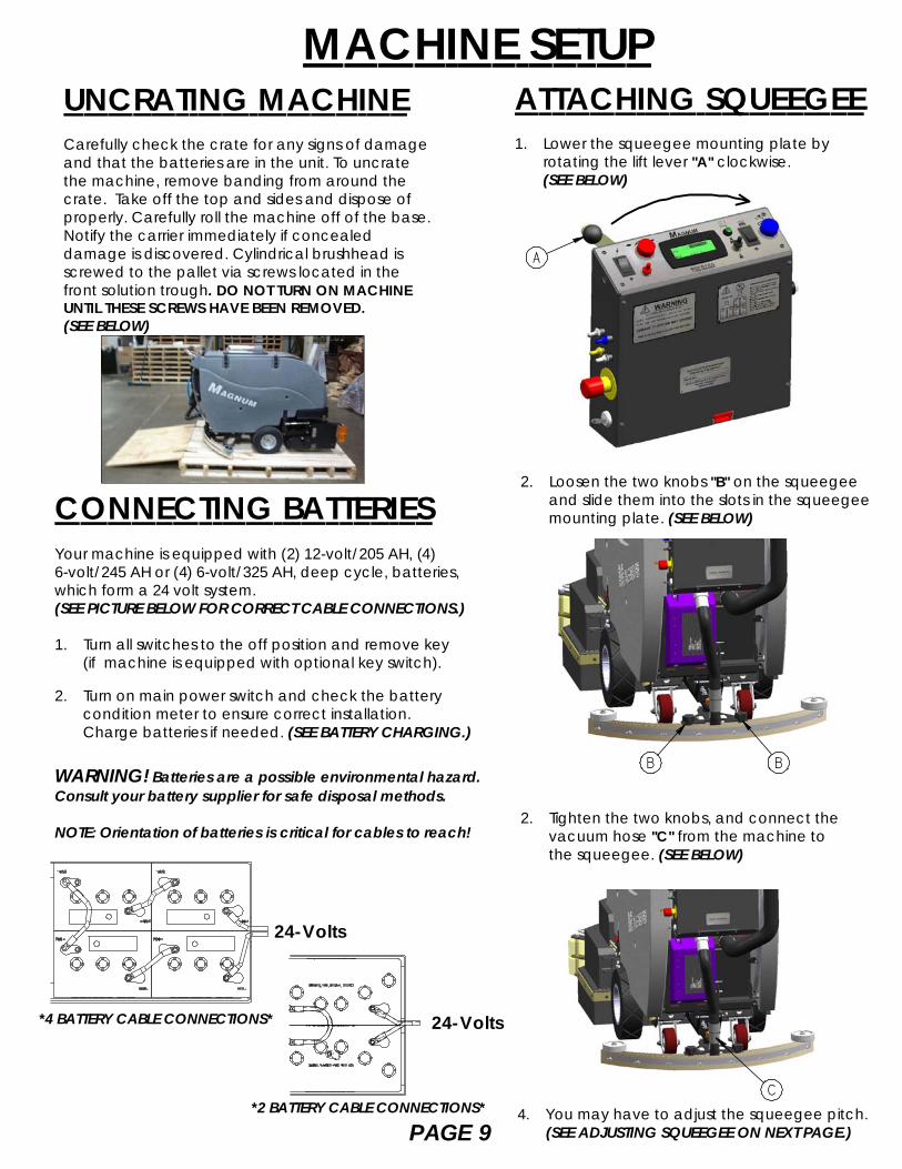
UNCRATING MACHINECarefully check the crate for any signs of damageand that the batteries are in the unit. To uncratethe machine, remove banding from around thecrate. Take off the top and sides and dispose ofproperly. Carefully roll the machine off of the base.Notify the carrier immediately if concealeddamage is discovered. Cylindrical brushhead isscrewed to the pallet via screws located in thefront solution trough. DO NOT TURN ON MACHINEUNTIL THESE SCREWS HAVE BEEN REMOVED.(SEE BELOW)
PAGE 9
MACHINE SETUP
CONNECTING BATTERIESYour machine is equipped with (2) 12-volt/205 AH, (4)6-volt/245 AH or (4) 6-volt/325 AH, deep cycle, batteries,which form a 24 volt system.(SEE PICTURE BELOW FOR CORRECT CABLE CONNECTIONS.)
1. Turn all switches to the off position and remove key (if machine is equipped with optional key switch).
2. Turn on main power switch and check the battery condition meter to ensure correct installation. Charge batteries if needed. (SEE BATTERY CHARGING.)
WARNING! Batteries are a possible environmental hazard.Consult your battery supplier for safe disposal methods.
NOTE: Orientation of batteries is critical for cables to reach!
2. Loosen the two knobs "B" on the squeegee and slide them into the slots in the squeegee mounting plate. (SEE BELOW)
ATTACHING SQUEEGEE1. Lower the squeegee mounting plate by rotating the lift lever "A" clockwise. (SEE BELOW)
4. You may have to adjust the squeegee pitch.(SEE ADJUSTING SQUEEGEE ON NEXT PAGE.)
*2 BATTERY CABLE CONNECTIONS*
2. Tighten the two knobs, and connect the vacuum hose "C" from the machine to the squeegee. (SEE BELOW)
BB
C
24-Volts
24-Volts*4 BATTERY CABLE CONNECTIONS*
A
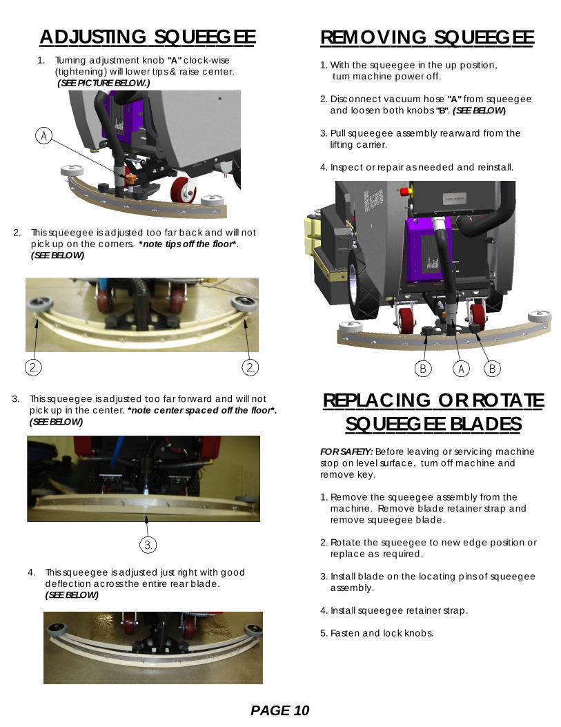
1. Turning adjustment knob "A" clock-wise (tightening) will lower tips & raise center.
(SEE PICTURE BELOW.)
2. This squeegee is adjusted too far back and will not pick up on the corners. *note tips off the floor*. (SEE BELOW)
3. This squeegee is adjusted too far forward and will not pick up in the center. *note center spaced off the floor*.
(SEE BELOW)
4. This squeegee is adjusted just right with good deflection across the entire rear blade. (SEE BELOW)
ADJUSTING SQUEEGEE
REPLACING OR ROTATESQUEEGEE BLADES
FOR SAFETY: Before leaving or servicing machinestop on level surface, turn off machine andremove key.
1. Remove the squeegee assembly from the machine. Remove blade retainer strap and remove squeegee blade.
2. Rotate the squeegee to new edge position or replace as required.
3. Install blade on the locating pins of squeegee assembly.
4. Install squeegee retainer strap.
5. Fasten and lock knobs.
REMOVING SQUEEGEE1. With the squeegee in the up position, turn machine power off.
2. Disconnect vacuum hose "A" from squeegee and loosen both knobs "B". (SEE BELOW)
3. Pull squeegee assembly rearward from the lifting carrier.
4. Inspect or repair as needed and reinstall.
PAGE 10
A BB2. 2.
A
3.
PAGE 11***FOR CORRECT PAD APPLICATION , CALL YOUR LOCAL DEALER***
1. Turn on machine power.
2. Raise the scrub deck by depressing the brush switch (O) to the up and off position and turn machine power back off.
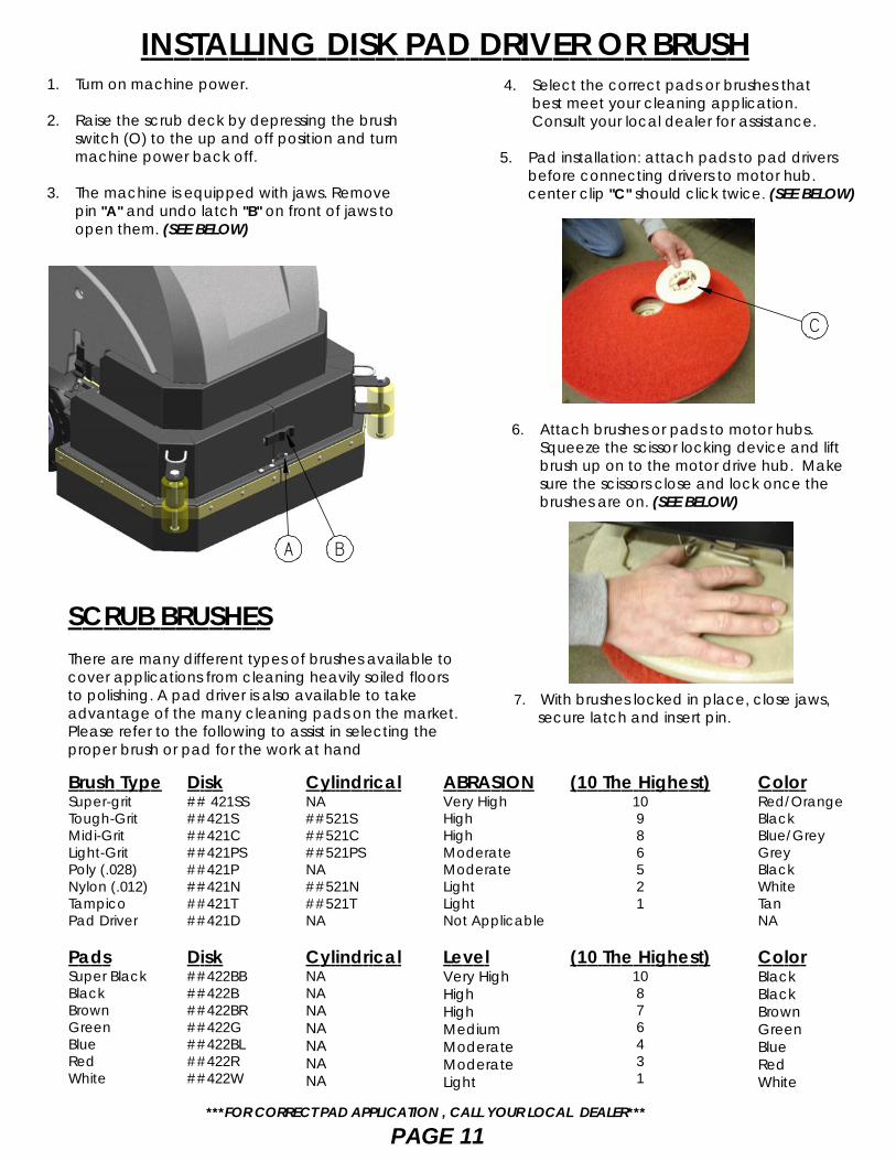
3. The machine is equipped with jaws. Remove pin "A" and undo latch "B" on front of jaws to open them. (SEE BELOW)
7. With brushes locked in place, close jaws, secure latch and insert pin.
4. Select the correct pads or brushes that best meet your cleaning application. Consult your local dealer for assistance.
5. Pad installation: attach pads to pad drivers before connecting drivers to motor hub. center clip "C" should click twice. (SEE BELOW)
6. Attach brushes or pads to motor hubs. Squeeze the scissor locking device and lift brush up on to the motor drive hub. Make sure the scissors close and lock once the brushes are on. (SEE BELOW)
INSTALLING DISK PAD DRIVER OR BRUSH
BA
C
SCRUB BRUSHESThere are many different types of brushes available tocover applications from cleaning heavily soiled floorsto polishing. A pad driver is also available to takeadvantage of the many cleaning pads on the market.Please refer to the following to assist in selecting theproper brush or pad for the work at hand
Disk## 421SS##421S##421C##421PS##421P##421N##421T##421D
Disk##422BB##422B##422BR##422G##422BL##422R##422W
CylindricalNA##521S##521C##521PSNA##521N##521TNA
CylindricalNANANANANANANA
(10 The Highest)10986521
(10 The Highest)10876431
Brush TypeSuper-gritTough-GritMidi-GritLight-GritPoly (.028)Nylon (.012)TampicoPad Driver
PadsSuper BlackBlackBrownGreenBlueRedWhite
ABRASIONVery HighHighHighModerateModerateLightLightNot Applicable
LevelVery HighHighHighMediumModerateModerateLight
ColorRed/OrangeBlackBlue/GreyGreyBlackWhiteTanNA
ColorBlackBlackBrownGreenBlueRedWhite
D
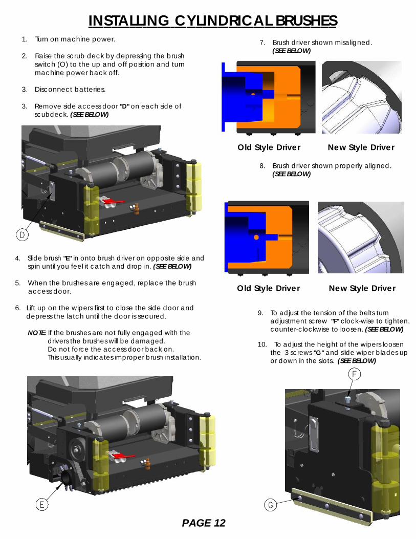
4. Slide brush "E" in onto brush driver on opposite side and spin until you feel it catch and drop in. (SEE BELOW)
5. When the brushes are engaged, replace the brush access door.
6. Lift up on the wipers first to close the side door and depress the latch until the door is secured.
NOTE: If the brushes are not fully engaged with the drivers the brushes will be damaged. Do not force the access door back on. This usually indicates improper brush installation.
E
PAGE 12
INSTALLING CYLINDRICAL BRUSHES1. Turn on machine power.
2. Raise the scrub deck by depressing the brush switch (O) to the up and off position and turn machine power back off.
3. Disconnect batteries.
3. Remove side access door "D" on each side of scubdeck. (SEE BELOW)
7. Brush driver shown misaligned. (SEE BELOW)
8. Brush driver shown properly aligned. (SEE BELOW)
9. To adjust the tension of the belts turn adjustment screw "F" clock-wise to tighten, counter-clockwise to loosen. (SEE BELOW)
10. To adjust the height of the wipers loosen the 3 screws "G" and slide wiper blades up or down in the slots. (SEE BELOW)
F
G
Old Style Driver New Style Driver
Old Style Driver New Style Driver
SIDE BROOM SYSTEM
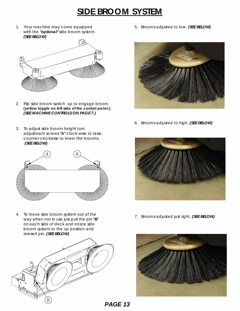
2. Flip side broom switch up to engage broom. (yellow toggle on left side of the control panel.) (SEE MACHINE CONTROLS ON PAGE 7.)
1. Your machine may come equipped with the "optional" side broom system. (SEE BELOW)
3. To adjust side broom height turn adjustment screws "A" clock-wise to raise, counter-clockwise to lower the brooms.
(SEE BELOW)
A A
5. Brooms adjusted to low. (SEE BELOW)
6. Brooms adjusted to high. (SEE BELOW)
7. Brooms adjusted just right. (SEE BELOW)
PAGE 13
4. To move side broom system out of the way when not in use just pull the pin "B" on each side of deck and rotate side broom system to the up position and reinsert pin. (SEE BELOW)
B
PAGE 14
PRE-CLEANING CHECK LISTRead and understand the safety section on pages 5 and 6before operating the machine.
1. Check battery condition gauge on the control panel. Make sure batteries are fully charged before using.
2. Check the condition of the pads or brushes.
3. Check the condition of the squeegee blades.
4. Transport the machine to the filling station. Raise the scrubhead and squeegee when transporting.
5. Turn machine off.
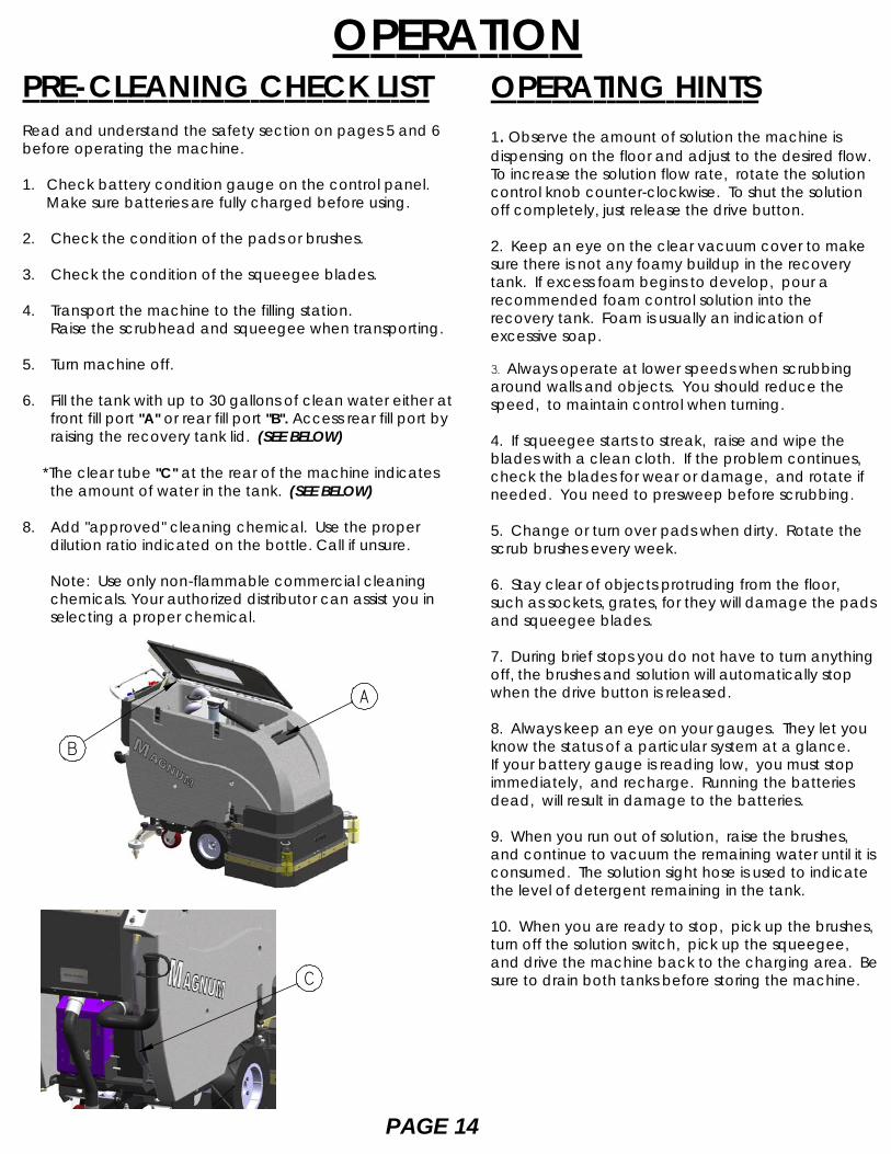
6. Fill the tank with up to 30 gallons of clean water either at front fill port "A" or rear fill port "B". Access rear fill port by raising the recovery tank lid. (SEE BELOW)
*The clear tube "C" at the rear of the machine indicates the amount of water in the tank. (SEE BELOW)
8. Add "approved" cleaning chemical. Use the proper dilution ratio indicated on the bottle. Call if unsure.
Note: Use only non-flammable commercial cleaning chemicals. Your authorized distributor can assist you in selecting a proper chemical.
OPERATIONOPERATING HINTS1. Observe the amount of solution the machine isdispensing on the floor and adjust to the desired flow.To increase the solution flow rate, rotate the solutioncontrol knob counter-clockwise. To shut the solutionoff completely, just release the drive button.
2. Keep an eye on the clear vacuum cover to makesure there is not any foamy buildup in the recoverytank. If excess foam begins to develop, pour arecommended foam control solution into therecovery tank. Foam is usually an indication ofexcessive soap.
3. Always operate at lower speeds when scrubbingaround walls and objects. You should reduce thespeed, to maintain control when turning.
4. If squeegee starts to streak, raise and wipe theblades with a clean cloth. If the problem continues,check the blades for wear or damage, and rotate ifneeded. You need to presweep before scrubbing.
5. Change or turn over pads when dirty. Rotate thescrub brushes every week.
6. Stay clear of objects protruding from the floor,such as sockets, grates, for they will damage the padsand squeegee blades.
7. During brief stops you do not have to turn anythingoff, the brushes and solution will automatically stopwhen the drive button is released.
8. Always keep an eye on your gauges. They let youknow the status of a particular system at a glance.If your battery gauge is reading low, you must stopimmediately, and recharge. Running the batteriesdead, will result in damage to the batteries.
9. When you run out of solution, raise the brushes,and continue to vacuum the remaining water until it isconsumed. The solution sight hose is used to indicatethe level of detergent remaining in the tank.
10. When you are ready to stop, pick up the brushes,turn off the solution switch, pick up the squeegee,and drive the machine back to the charging area. Besure to drain both tanks before storing the machine.C
A
B
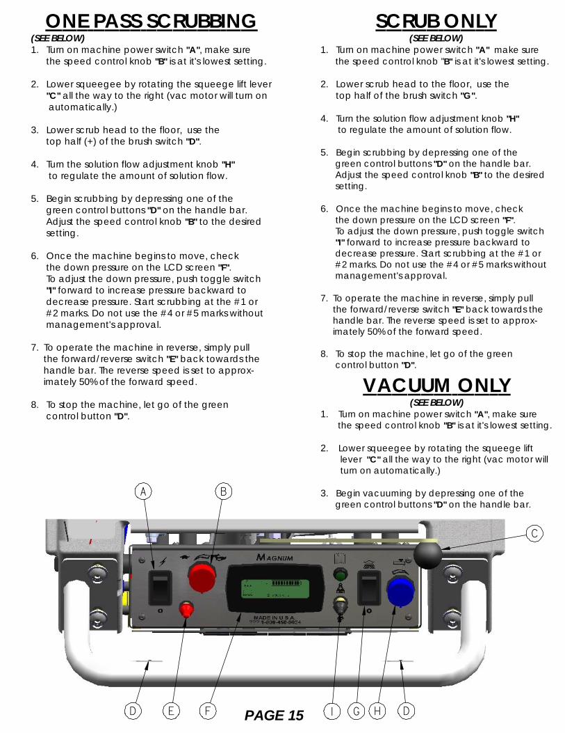
ONE PASS SCRUBBING(SEE BELOW)1. Turn on machine power switch "A", make sure the speed control knob "B" is at it's lowest setting.
2. Lower squeegee by rotating the squeege lift lever "C" all the way to the right (vac motor will turn on
automatically.)
3. Lower scrub head to the floor, use the top half (+) of the brush switch "D".
4. Turn the solution flow adjustment knob "H" to regulate the amount of solution flow.
5. Begin scrubbing by depressing one of the green control buttons "D" on the handle bar. Adjust the speed control knob "B" to the desired setting.
6. Once the machine begins to move, check the down pressure on the LCD screen "F". To adjust the down pressure, push toggle switch
"I" forward to increase pressure backward to decrease pressure. Start scrubbing at the #1 or #2 marks. Do not use the #4 or #5 marks without management's approval.
7. To operate the machine in reverse, simply pull the forward/reverse switch "E" back towards the handle bar. The reverse speed is set to approx- imately 50% of the forward speed.
8. To stop the machine, let go of the green control button "D".
PAGE 15
SCRUB ONLY(SEE BELOW)
1. Turn on machine power switch "A" make sure the speed control knob "B" is at it's lowest setting.
2. Lower scrub head to the floor, use the top half of the brush switch "G".
4. Turn the solution flow adjustment knob "H" to regulate the amount of solution flow.
5. Begin scrubbing by depressing one of the green control buttons "D" on the handle bar. Adjust the speed control knob "B" to the desired setting.
6. Once the machine begins to move, check the down pressure on the LCD screen "F". To adjust the down pressure, push toggle switch
"I" forward to increase pressure backward to decrease pressure. Start scrubbing at the #1 or #2 marks. Do not use the #4 or #5 marks without management's approval.
7. To operate the machine in reverse, simply pull the forward/reverse switch "E" back towards the handle bar. The reverse speed is set to approx- imately 50% of the forward speed.
8. To stop the machine, let go of the green control button "D".
VACUUM ONLY(SEE BELOW)
1. Turn on machine power switch "A", make sure the speed control knob "B" is at it's lowest setting.
2. Lower squeegee by rotating the squeege lift lever "C" all the way to the right (vac motor will turn on automatically.)
3. Begin vacuuming by depressing one of the green control buttons "D" on the handle bar.
C
A
G H DD F
B
E I
PAGE 16
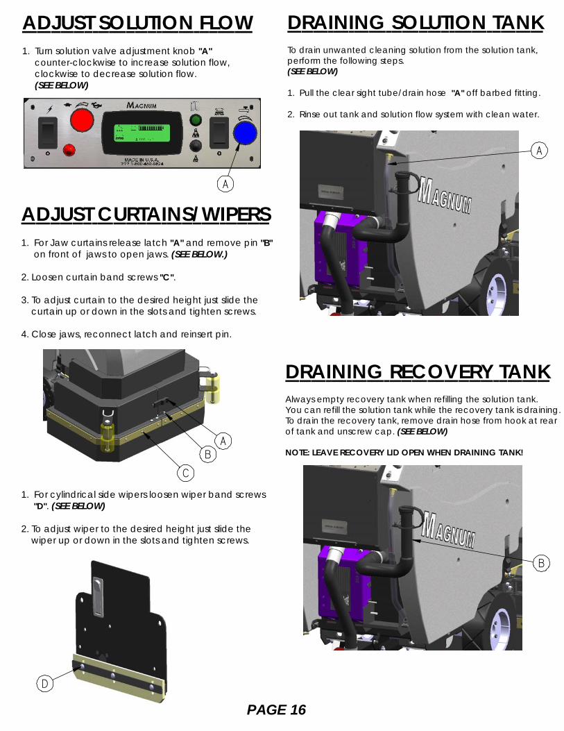
DRAINING SOLUTION TANKTo drain unwanted cleaning solution from the solution tank,perform the following steps.(SEE BELOW)
1. Pull the clear sight tube/drain hose "A" off barbed fitting.
2. Rinse out tank and solution flow system with clean water.
ADJUST SOLUTION FLOW1. Turn solution valve adjustment knob "A"
counter-clockwise to increase solution flow, clockwise to decrease solution flow.
(SEE BELOW)
DRAINING RECOVERY TANKAlways empty recovery tank when refilling the solution tank.You can refill the solution tank while the recovery tank is draining.To drain the recovery tank, remove drain hose from hook at rearof tank and unscrew cap. (SEE BELOW)
NOTE: LEAVE RECOVERY LID OPEN WHEN DRAINING TANK!
A
AB
A
B
ADJUST CURTAINS/WIPERS1. For Jaw curtains release latch "A" and remove pin "B" on front of jaws to open jaws. (SEE BELOW.)
2. Loosen curtain band screws "C".
3. To adjust curtain to the desired height just slide the curtain up or down in the slots and tighten screws.
4. Close jaws, reconnect latch and reinsert pin.
C
1. For cylindrical side wipers loosen wiper band screws "D". (SEE BELOW)
2. To adjust wiper to the desired height just slide the wiper up or down in the slots and tighten screws.
D
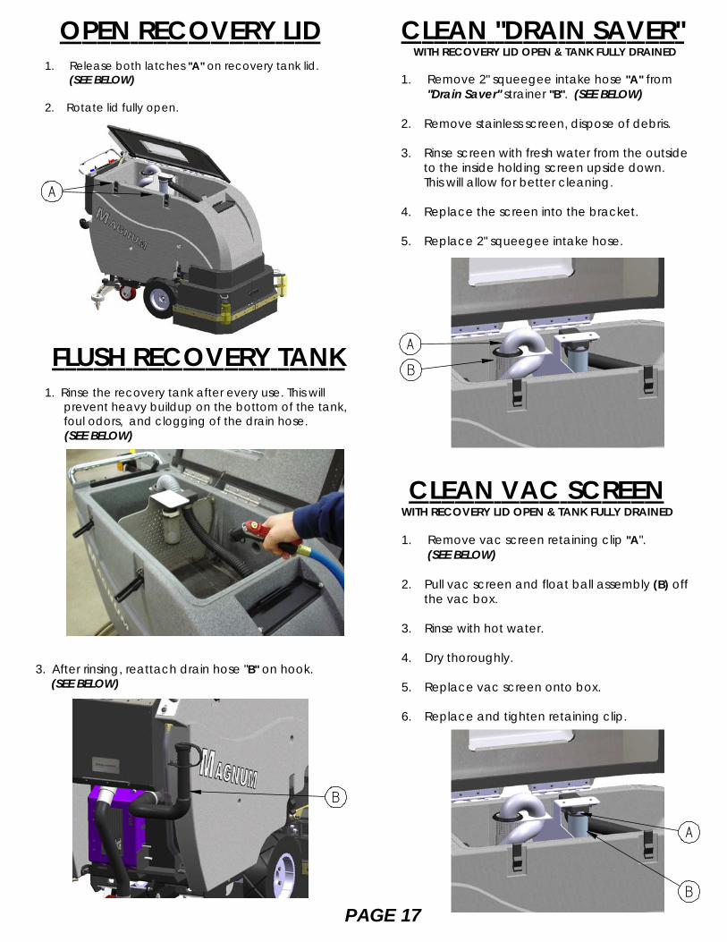
OPEN RECOVERY LID1. Release both latches "A" on recovery tank lid.
(SEE BELOW)
2. Rotate lid fully open.
CLEAN "DRAIN SAVER" WITH RECOVERY LID OPEN & TANK FULLY DRAINED
1. Remove 2" squeegee intake hose "A" from"Drain Saver" strainer "B". (SEE BELOW)
2. Remove stainless screen, dispose of debris.
3. Rinse screen with fresh water from the outside to the inside holding screen upside down. This will allow for better cleaning.
4. Replace the screen into the bracket.
5. Replace 2" squeegee intake hose.
FLUSH RECOVERY TANK1. Rinse the recovery tank after every use. This will prevent heavy buildup on the bottom of the tank, foul odors, and clogging of the drain hose. (SEE BELOW)
3. After rinsing, reattach drain hose "B" on hook. (SEE BELOW)
CLEAN VAC SCREENWITH RECOVERY LID OPEN & TANK FULLY DRAINED
1. Remove vac screen retaining clip "A".(SEE BELOW)
2. Pull vac screen and float ball assembly (B) off the vac box.
3. Rinse with hot water.
4. Dry thoroughly.
5. Replace vac screen onto box.
6. Replace and tighten retaining clip.
A
B
A
B
A
PAGE 17
B
PAGE 18
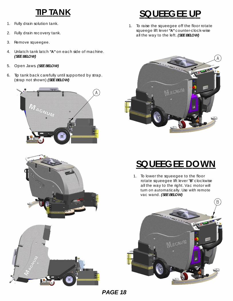
TIP TANK1. Fully drain solution tank.
2. Fully drain recovery tank.
3. Remove squeegee.
4. Unlatch tank latch "A" on each side of machine.(SEE BELOW)
5. Open Jaws. (SEE BELOW)
6. Tip tank back carefully until supported by strap. (strap not shown) (SEE BELOW)
SQUEEGEE UP1. To raise the squeegee off the floor rotate squeege lift lever "A" counter-clock-wise all the way to the left. (SEE BELOW)
SQUEEGEE DOWN1. To lower the squeegee to the floor rotate squeegee lift lever "B" clockwise all the way to the right. Vac motor will turn on automatically. Use with remote vac wand. (SEE BELOW)
A
A
B
DECK HEIGHTADJUSTMENT
VAC MOTOR(SEE BELOW)
SOLUTION FILTER
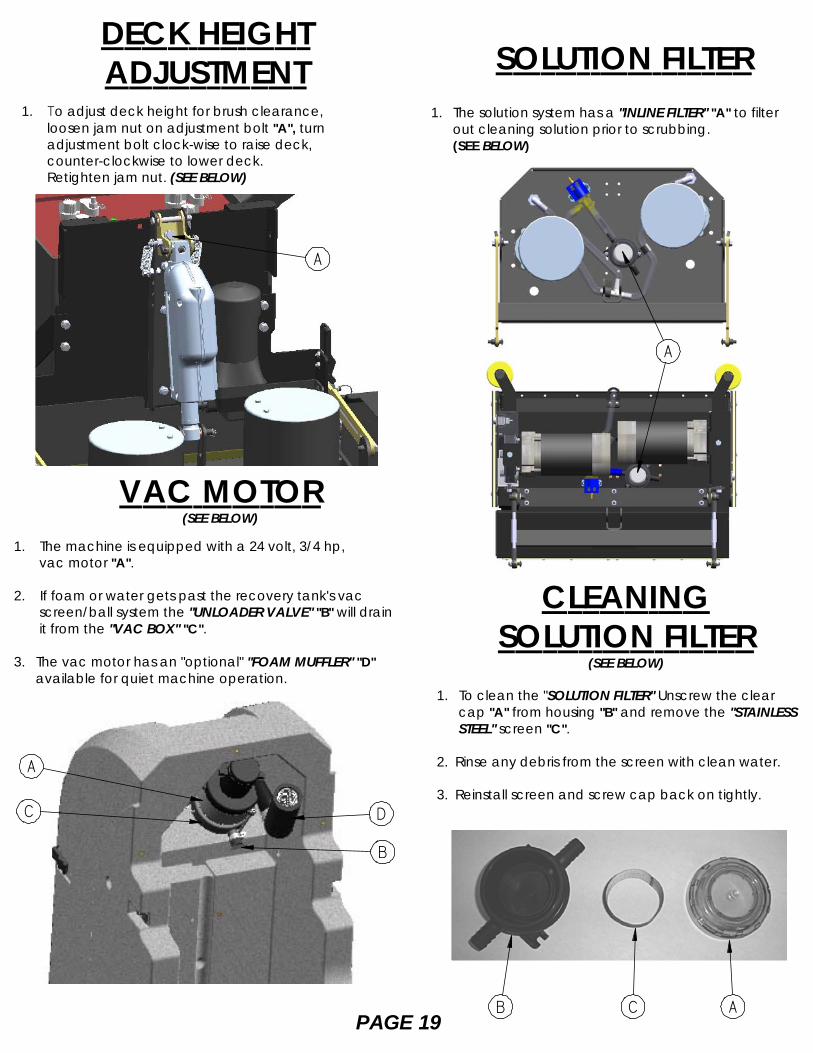
1. The machine is equipped with a 24 volt, 3/4 hp, vac motor "A".
2. If foam or water gets past the recovery tank's vac screen/ball system the "UNLOADER VALVE" "B" will drain it from the "VAC BOX" "C".
3. The vac motor has an "optional" "FOAM MUFFLER" "D" available for quiet machine operation.
1. The solution system has a "INLINE FILTER" "A" to filter out cleaning solution prior to scrubbing.
(SEE BELOW)
CLEANINGSOLUTION FILTER
(SEE BELOW)
1. To clean the "SOLUTION FILTER" Unscrew the clear cap "A" from housing "B" and remove the "STAINLESS STEEL" screen "C".
2. Rinse any debris from the screen with clean water.
3. Reinstall screen and screw cap back on tightly.
PAGE 19B C A
A
A
B
DC
1. To adjust deck height for brush clearance, loosen jam nut on adjustment bolt "A", turn adjustment bolt clock-wise to raise deck, counter-clockwise to lower deck. Retighten jam nut. (SEE BELOW)
A
PAGE 20
BATTERY CHARGINGCAUTION:The following instructions are intended for the 24v charger supplied with the machine.
Do not use any other charger with this machine.
CHARGER SPECIFICATIONS
* OUTPUT VOLTAGE OF 24 VOLTS.
* OUTPUT CURRENT OF 25 AMPS MAX (STANDARD).
* OUTPUT CURRENT OF 36 AMPS MAX (OPTIONAL).
* INPUT VOLTAGE OF 110 VOLTS/60 HZ.
* AUTOMATIC SHUT OFF CIRCUIT.
* MADE FOR DEEP CYCLE BATTERIES.
DANGER: Always charge batteries in a well ventilated area.Batteries emit hydrogen gas. Explosion or fire can result.Keep sparks and flame away. Shield eyes when servicingbatteries and avoid contact with battery acid.
1. Transport machine to a well ventilated area for charging.
2. Turn the machine off.
3. CAUTION ALWAYS WEAR EYE PROTECTION WHEN BATTERIES ARE EXPOSED.
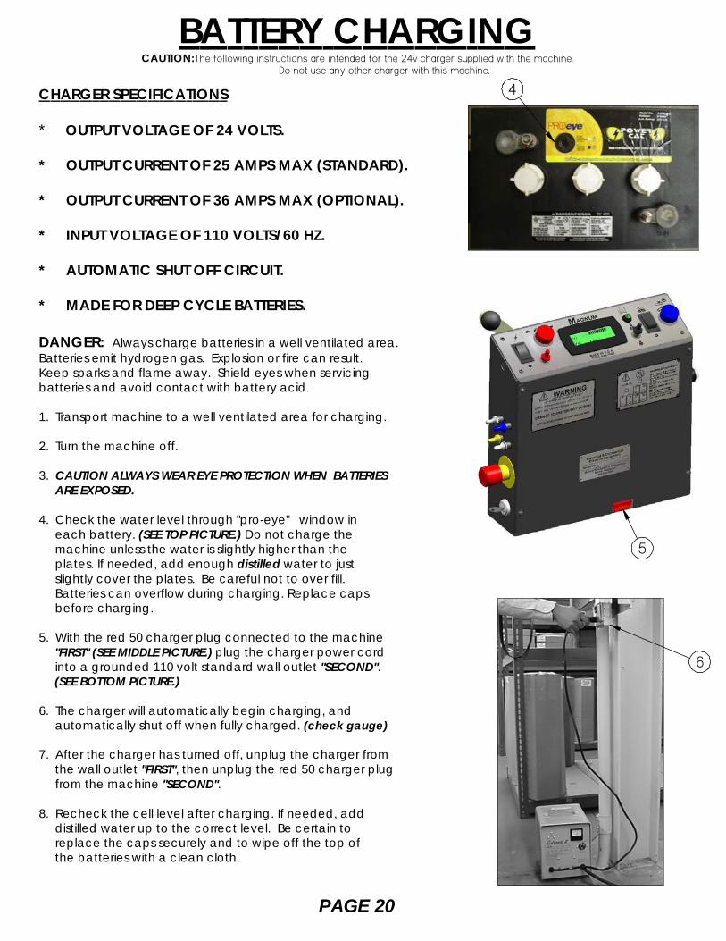
4. Check the water level through "pro-eye" window in each battery. (SEE TOP PICTURE.) Do not charge the machine unless the water is slightly higher than the plates. If needed, add enough distilled water to just slightly cover the plates. Be careful not to over fill. Batteries can overflow during charging. Replace caps before charging.
5. With the red 50 charger plug connected to the machine "FIRST" (SEE MIDDLE PICTURE.) plug the charger power cord into a grounded 110 volt standard wall outlet "SECOND". (SEE BOTTOM PICTURE.)
6. The charger will automatically begin charging, and automatically shut off when fully charged. (check gauge)
7. After the charger has turned off, unplug the charger from the wall outlet "FIRST", then unplug the red 50 charger plug from the machine "SECOND".
8. Recheck the cell level after charging. If needed, add distilled water up to the correct level. Be certain to replace the caps securely and to wipe off the top of the batteries with a clean cloth.
6
4
5
PAGE 21
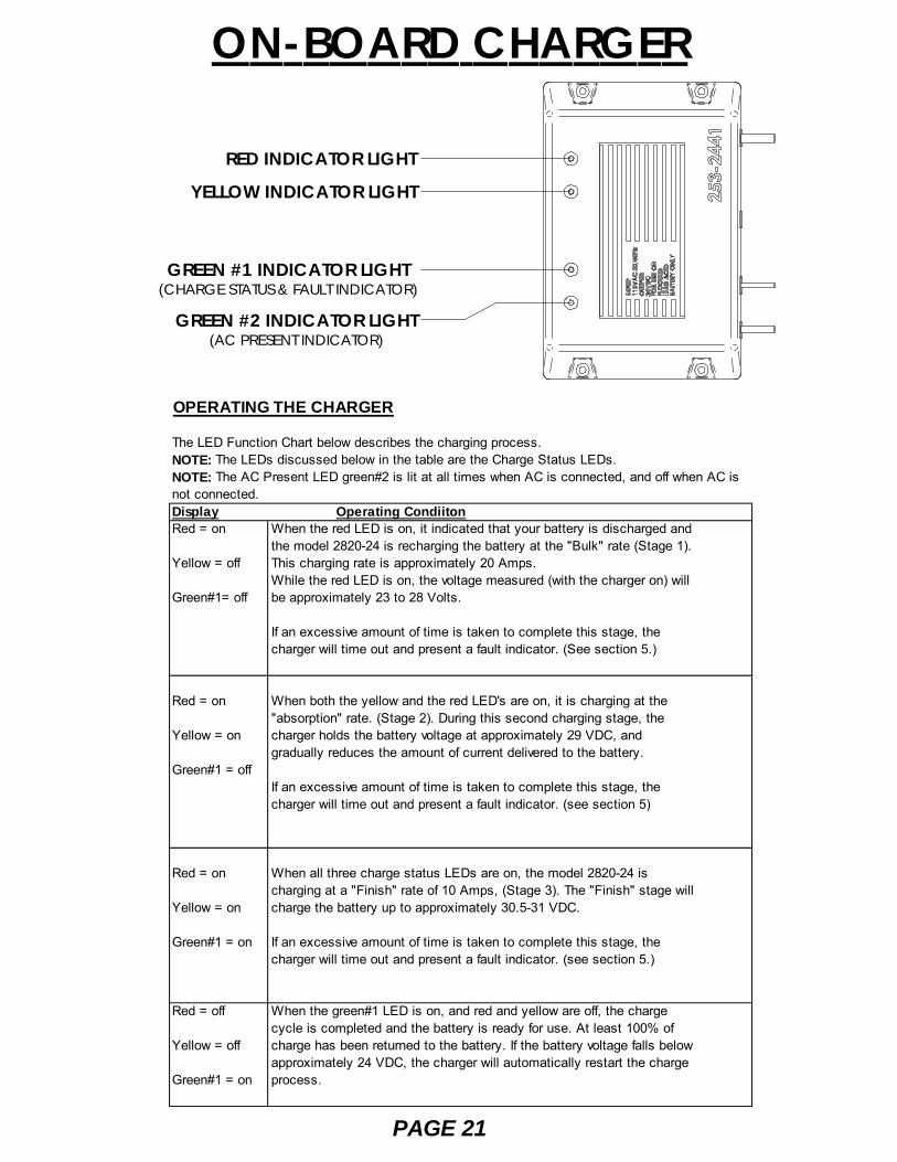
ON-BOARD CHARGER
RED INDICATOR LIGHT
YELLOW INDICATOR LIGHT
GREEN #1 INDICATOR LIGHT(CHARGE STATUS & FAULT INDICATOR)
GREEN #2 INDICATOR LIGHT(AC PRESENT INDICATOR)
OPERATING THE CHARGER
The LED Function Chart below describes the charging process.NOTE: The LEDs discussed below in the table are the Charge Status LEDs.NOTE: The AC Present LED green#2 is lit at all times when AC is connected, and off when AC isnot connected.Display Operating CondiitonRed = on When the red LED is on, it indicated that your battery is discharged and
the model 2820-24 is recharging the battery at the "Bulk" rate (Stage 1).Yellow = off This charging rate is approximately 20 Amps.
While the red LED is on, the voltage measured (with the charger on) willGreen#1= off be approximately 23 to 28 Volts.
If an excessive amount of time is taken to complete this stage, thecharger will time out and present a fault indicator. (See section 5.)
Red = on When both the yellow and the red LED's are on, it is charging at the"absorption" rate. (Stage 2). During this second charging stage, the
Yellow = on charger holds the battery voltage at approximately 29 VDC, andgradually reduces the amount of current delivered to the battery.
Green#1 = offIf an excessive amount of time is taken to complete this stage, thecharger will time out and present a fault indicator. (see section 5)
Red = on When all three charge status LEDs are on, the model 2820-24 ischarging at a "Finish" rate of 10 Amps, (Stage 3). The "Finish" stage will
Yellow = on charge the battery up to approximately 30.5-31 VDC.
Green#1 = on If an excessive amount of time is taken to complete this stage, thecharger will time out and present a fault indicator. (see section 5.)
Red = off When the green#1 LED is on, and red and yellow are off, the chargecycle is completed and the battery is ready for use. At least 100% of
Yellow = off charge has been returned to the battery. If the battery voltage falls belowapproximately 24 VDC, the charger will automatically restart the charge
Green#1 = on process.
ON-BOARD CHARGER
PAGE 22
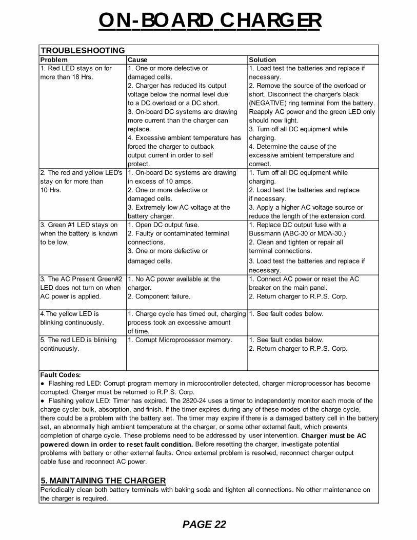
TROUBLESHOOTINGProblem Cause Solution1. Red LED stays on for 1. One or more defective or 1. Load test the batteries and replace ifmore than 18 Hrs. damaged cells. necessary.
2. Charger has reduced its output 2. Remove the source of the overload orvoltage below the normal level due short. Disconnect the charger's blackto a DC overload or a DC short. (NEGATIVE) ring terminal from the battery.3. On-board DC systems are drawing Reapply AC power and the green LED onlymore current than the charger can should now light.replace. 3. Turn off all DC equipment while 4. Excessive ambient temperature has charging.forced the charger to cutback 4. Determine the cause of theoutput current in order to self excessive ambient temperature andprotect. correct.
2. The red and yellow LED's 1. On-board Dc systems are drawing 1. Turn off all DC equipment whilestay on for more than in excess of 10 amps. charging.10 Hrs. 2. One or more defective or 2. Load test the batteries and replace
damaged cells. if necessary.3. Extremely low AC voltage at the 3. Apply a higher AC voltage source or battery charger. reduce the length of the extension cord.
3. Green #1 LED stays on 1. Open DC output fuse. 1. Replace DC output fuse with awhen the battery is known 2. Faulty or contaminated terminal Bussmann (ABC-30 or MDA-30.)to be low. connections. 2. Clean and tighten or repair all
3. One or more defective or terminal connections.damaged cells. 3. Load test the batteries and replace if
necessary.3. The AC Present Green#2 1. No AC power available at the 1. Connect AC power or reset the ACLED does not turn on when charger. breaker on the main panel.AC power is applied. 2. Component failure. 2. Return charger to R.P.S. Corp.
4.The yellow LED is 1. Charge cycle has timed out, charging 1. See fault codes below.blinking continuously. process took an excessive amount
of time.5. The red LED is blinking 1. Corrupt Microprocessor memory. 1. See fault codes below.continuously. 2. Return charger to R.P.S. Corp.
Fault Codes:● Flashing red LED: Corrupt program memory in microcontroller detected, charger microprocessor has becomecorrupted. Charger must be returned to R.P.S. Corp.● Flashing yellow LED: Timer has expired. The 2820-24 uses a timer to independently monitor each mode of thecharge cycle: bulk, absorption, and finish. If the timer expires during any of these modes of the charge cycle,there could be a problem with the battery set. The timer may expire if there is a damaged battery cell in the batteryset, an abnormally high ambient temperature at the charger, or some other external fault, which preventscompletion of charge cycle. These problems need to be addressed by user intervention. Charger must be ACpowered down in order to reset fault condition. Before resetting the charger, investigate potentialproblems with battery or other external faults. Once external problem is resolved, reconnect charger outputcable fuse and reconnect AC power.
5. MAINTAINING THE CHARGERPeriodically clean both battery terminals with baking soda and tighten all connections. No other maintenance onthe charger is required.
PAGE 23
OPERATING MANUALGENERAL INFORMATION AND WARNING • Electronic automatic battery charger with microprocessor suitable for any battery type. • Fully automatic charging cycle with electronic setting; protected against overload, short‐circuit
at clamps and reversed polarity. • Never disconnect the battery while charging: this could cause sparks. • Never use the equipment in the rain, in areas used for washing and in damp areas. • Before starting to charge, make sure the voltage of the equipment suits the voltage of the
battery and that the selected charging curve (for lead‐acid free batteries and airtight gel batteries) is correct for the type of battery to be charged. In addition, make sure the rated inputvoltage of the charger suits the available supply voltage and the system is equipped with grounding.
• If necessary, replace the fuse with another of the same type and value as indicated on the ratingplate.
• Pay attention to any remarks of the battery manufacturer. For lead‐acid batteries with liquid electrolyte:
• Control the water level after each charging process. • Refill with distilled water only. • Caution! The gases generated during charging are explosive. Do not smoke in the vicinity of the
batteries. When working with cables and electrical equipment, avoid open flame and sparks. • Attention: Use protective glasses and gloves during battery maintenance. Battery acid causes
injuries. In case of contact with battery acid, wash the affected parts with a lot of fresh waterand consult a doctor if necessary.
CONTROLS (see figure behind the cover)
1. Three‐digit display + symbol (1), to view A =the charging current, U = the battery voltage, h = thecharging time, C = the charging ampere‐hours [AH], E = the energy used [KWh].
2. Button for the Selection of the display mode (2): A, U, h, C, E. After about 10 seconds the display returns to the visualization of the charging current.
3. Red control indicator (3): when it is on, the charging cycle has started. 4. Yellow control indicator (4): when it is on, the final phase of the charging cycle has started. 5. Green control indicator (5): when it is on, the charging cycle has finished.
OPERATION
• Plug the cord into the socket. • Connect the battery, checking the polarity. • Now, the battery charger’s display will show a sequence of details on the charger’s internal
programming: after the name “SPE”, it will show the software release installed in theequipment, then, in sequence, the following parameters: battery voltage, charging current,charging curve number, and finally the words “GEL” or “Acd” depending on the set up charging curve being suitable for airtight gel batteries or lead‐acid batteries. Make sure the type of batteries to be charged (gel or lead‐acid batteries) matches the displayed details (“GEL” or“Acd”, respectively). If it doesn’t, contact our dealer. Now, a test is run on the battery voltage to decide if the charging process should be started or not. If the battery is not connected to thebattery charger, the display will show the word “bat”. The word will stay on, even if the test is failed (for instance, reversed polarities or incorrect battery connection). If the test is passed, thedisplay will show the battery voltage for approximately 5 seconds and the battery will begin to
BATTERY CHARGER
*continued on next page*
PAGE 24
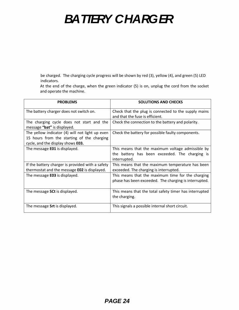
be charged. The charging cycle progress will be shown by red (3), yellow (4), and green (5) LED indicators.
At the end of the charge, when the green indicator (5) is on, unplug the cord from the socket and operate the machine.
PROBLEMS SOLUTIONS AND CHECKS
The battery charger does not switch on. Check that the plug is connected to the supply mains and that the fuse is efficient.
The charging cycle does not start and the message “bat” is displayed.
Check the connection to the battery and polarity.
The yellow indicator (4) will not light up even 15 hours from the starting of the charging cycle, and the display shows E03.
Check the battery for possible faulty components.
The message E01 is displayed. This means that the maximum voltage admissible by the battery has been exceeded. The charging is interrupted.
If the battery charger is provided with a safety thermostat and the message E02 is displayed.
This means that the maximum temperature has been exceeded. The charging is interrupted.
The message E03 is displayed. This means that the maximum time for the charging phase has been exceeded. The charging is interrupted.
The message SCt is displayed. This means that the total safety timer has interrupted the charging.
The message Srt is displayed. This signals a possible internal short circuit.
BATTERY CHARGER
PAGE 25
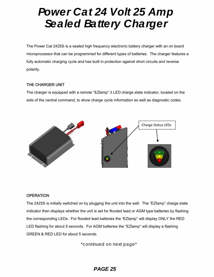
Power Cat 24 Volt 25 AmpSealed Battery Charger
The Power Cat 2425S is a sealed high frequency electronic battery charger with an on board
microprocessor that can be programmed for different types of batteries. The charger features a
fully automatic charging cycle and has built in protection against short circuits and reverse
polarity.
THE CHARGER UNIT
The charger is equipped with a remote “EZlamp” 3 LED charge state indicator, located on the
side of the central command, to show charge cycle information as well as diagnostic codes.
OPERATION
The 2425S is initially switched on by plugging the unit into the wall. The “EZlamp” charge state
indicator then displays whether the unit is set for flooded lead or AGM type batteries by flashing
the corresponding LEDs. For flooded lead batteries the “EZlamp” will display ONLY the RED
LED flashing for about 5 seconds. For AGM batteries the “EZlamp” will display a flashing
GREEN & RED LED for about 5 seconds.
Charge Status LEDs
*continued on next page*
PAGE 26
Power Cat 24 Volt 25 AmpSealed Battery Charger
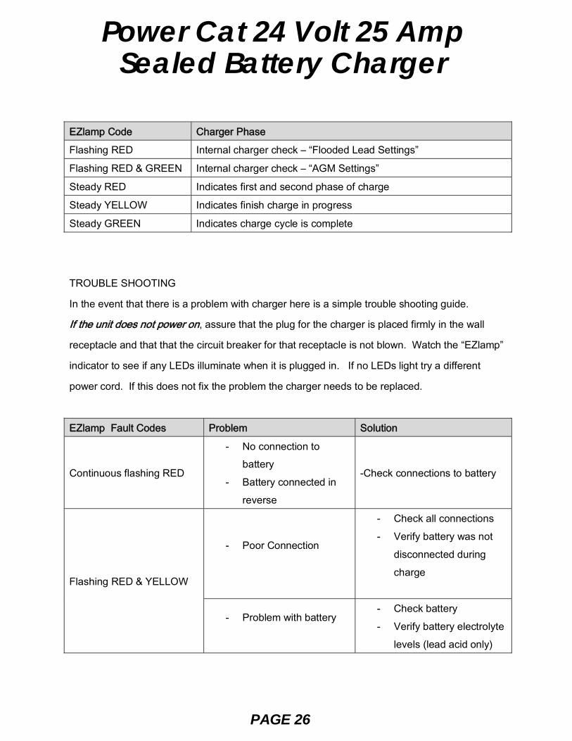
EZlamp Code Charger Phase
Flashing RED Internal charger check – “Flooded Lead Settings”
Flashing RED & GREEN Internal charger check – “AGM Settings”
Steady RED Indicates first and second phase of charge
Steady YELLOW Indicates finish charge in progress
Steady GREEN Indicates charge cycle is complete
TROUBLE SHOOTING
In the event that there is a problem with charger here is a simple trouble shooting guide.
If the unit does not power on, assure that the plug for the charger is placed firmly in the wall
receptacle and that that the circuit breaker for that receptacle is not blown. Watch the “EZlamp”
indicator to see if any LEDs illuminate when it is plugged in. If no LEDs light try a different
power cord. If this does not fix the problem the charger needs to be replaced.
EZlamp Fault Codes Problem Solution
Continuous flashing RED
- No connection to battery
- Battery connected in reverse
-Check connections to battery
Flashing RED & YELLOW
- Poor Connection
- Check all connections - Verify battery was not
disconnected during charge
- Problem with battery
- Check battery - Verify battery electrolyte
levels (lead acid only)
PAGE 27
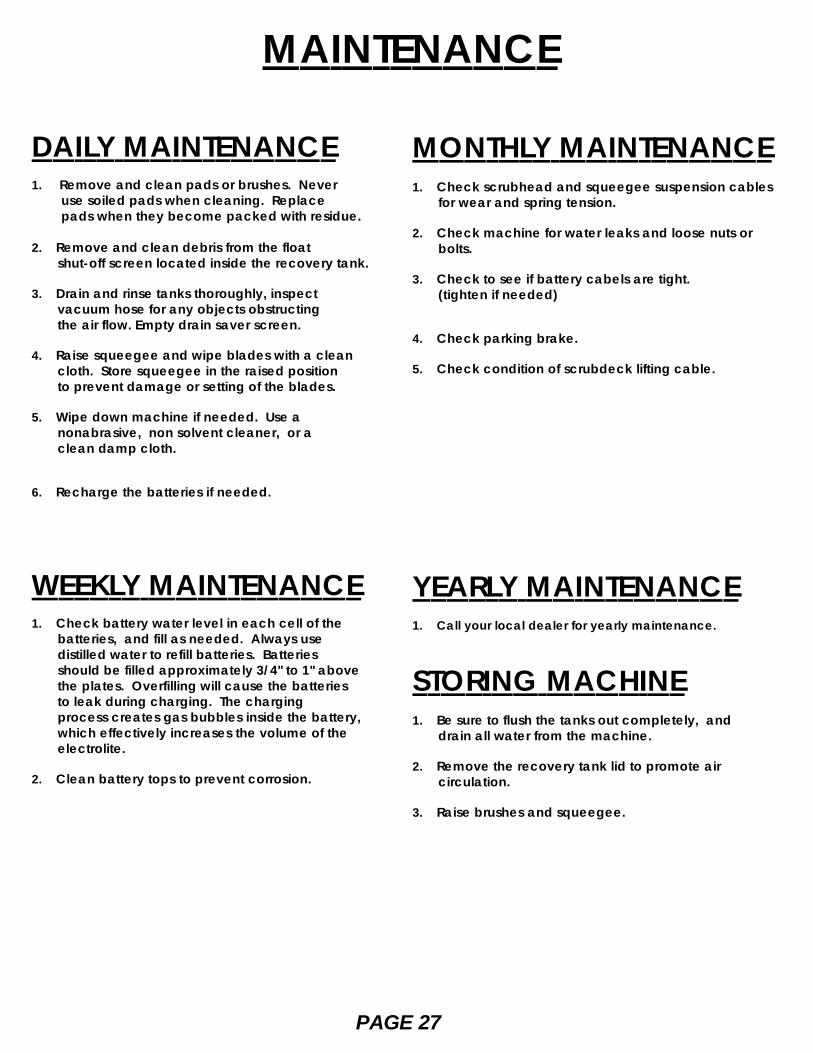
MONTHLY MAINTENANCE1. Check scrubhead and squeegee suspension cables for wear and spring tension.
2. Check machine for water leaks and loose nuts or bolts.
3. Check to see if battery cabels are tight. (tighten if needed)
4. Check parking brake.
5. Check condition of scrubdeck lifting cable.
YEARLY MAINTENANCE1. Call your local dealer for yearly maintenance.
STORING MACHINE1. Be sure to flush the tanks out completely, and drain all water from the machine.
2. Remove the recovery tank lid to promote air circulation.
3. Raise brushes and squeegee.
DAILY MAINTENANCE1. Remove and clean pads or brushes. Never use soiled pads when cleaning. Replace pads when they become packed with residue.
2. Remove and clean debris from the float shut-off screen located inside the recovery tank.
3. Drain and rinse tanks thoroughly, inspect vacuum hose for any objects obstructing the air flow. Empty drain saver screen.
4. Raise squeegee and wipe blades with a clean cloth. Store squeegee in the raised position to prevent damage or setting of the blades.
5. Wipe down machine if needed. Use a nonabrasive, non solvent cleaner, or a clean damp cloth.
6. Recharge the batteries if needed.
WEEKLY MAINTENANCE1. Check battery water level in each cell of the batteries, and fill as needed. Always use distilled water to refill batteries. Batteries should be filled approximately 3/4" to 1" above the plates. Overfilling will cause the batteries to leak during charging. The charging process creates gas bubbles inside the battery, which effectively increases the volume of the electrolite.
2. Clean battery tops to prevent corrosion.
MAINTENANCE
PAGE 28
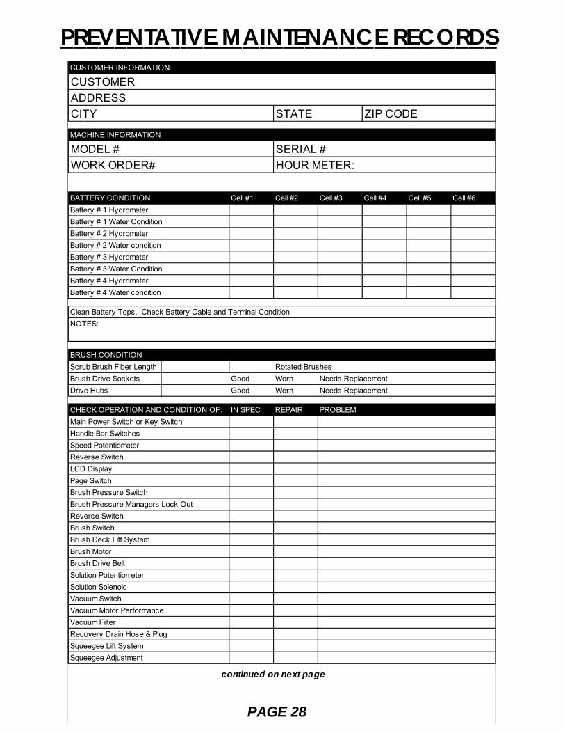
PREVENTATIVE MAINTENANCE RECORDS
continued on next page
CUSTOMER INFORMATION
CUSTOMERADDRESSCITY STATE ZIP CODE
MACHINE INFORMATION
MODEL # SERIAL #WORK ORDER# HOUR METER:
BATTERY CONDITION Cell #1 Cell #2 Cell #3 Cell #4 Cell #5 Cell #6Battery # 1 Hydrometer Battery # 1 Water Condition Battery # 2 Hydrometer Battery # 2 Water condition Battery # 3 Hydrometer Battery # 3 Water Condition Battery # 4 Hydrometer Battery # 4 Water condition
Clean Battery Tops. Check Battery Cable and Terminal ConditionNOTES:
BRUSH CONDITIONScrub Brush Fiber Length Rotated BrushesBrush Drive Sockets Good Worn Needs ReplacementDrive Hubs Good Worn Needs Replacement
CHECK OPERATION AND CONDITION OF: IN SPEC REPAIR PROBLEMMain Power Switch or Key SwitchHandle Bar SwitchesSpeed PotentiometerReverse SwitchLCD DisplayPage SwitchBrush Pressure Switch Brush Pressure Managers Lock OutReverse SwitchBrush SwitchBrush Deck Lift SystemBrush MotorBrush Drive BeltSolution PotentiometerSolution SolenoidVacuum SwitchVacuum Motor PerformanceVacuum FilterRecovery Drain Hose & PlugSqueegee Lift SystemSqueegee Adjustment

PAGE 29
PREVENTATIVE MAINTENANCE RECORDS
continued from previous page
CHECK OPERATION AND CONDITION OF: IN SPEC REPAIR PROBLEMSpray Jet SwitchSpray Jet Pump, Hose & NozzleBattery Charger ConnectorsBattery Charger
CLEAN AND/OR LUBRICATE IN SPEC REPAIR PROBLEMSolution FilterSqueegee Pivot Points & KnobsScrub Deck LinkageCaster grease fittingsSqueegee Knob ThreadsSqueegee Pivot PointsBrush Head Pivot Points
VISUALLY INSPECT: IN SPEC REPAIR PROBLEMSolution Tank ConditionRecovery Tank & Lid ConditionDrain SaverVacuum FloatVacuum Motor BrushesVacuum HosesVacuum FilterSolution HosesSqueegee Tool and ThroatSqueegee BladesBlade retainers & HardwareSqueegee WheelsBrush SkirtsBrush Motor BrushesBrush or Pad Driver ConditionDrive Wheel ConditionCaster Condition
COMMENTS
Technician's Name
Technician's Signature Date
Customer's Name:
Customer's Signature Date
©2006 R.P.S. Corporation
PAGE 30
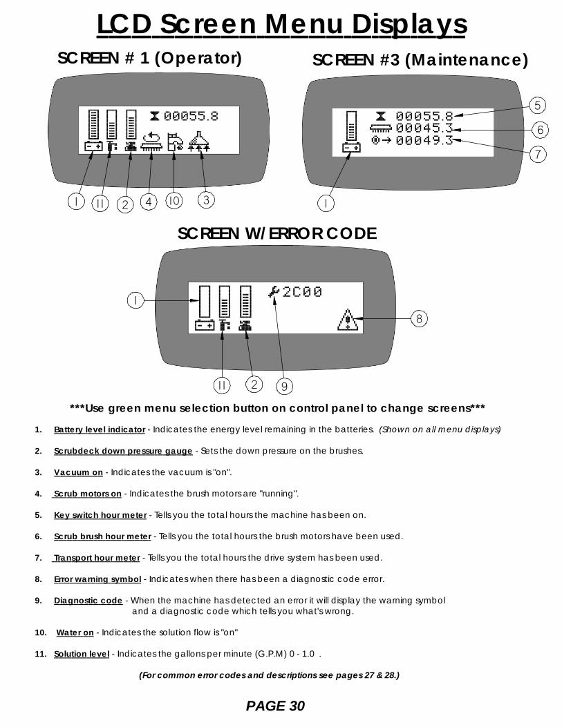
1. Battery level indicator - Indicates the energy level remaining in the batteries. (Shown on all menu displays)
2. Scrubdeck down pressure gauge - Sets the down pressure on the brushes.
3. Vacuum on - Indicates the vacuum is "on".
4. Scrub motors on - Indicates the brush motors are "running".
5. Key switch hour meter - Tells you the total hours the machine has been on.
6. Scrub brush hour meter - Tells you the total hours the brush motors have been used.
7. Transport hour meter - Tells you the total hours the drive system has been used.
8. Error warning symbol - Indicates when there has been a diagnostic code error.
9. Diagnostic code - When the machine has detected an error it will display the warning symbol and a diagnostic code which tells you what's wrong.
10. Water on - Indicates the solution flow is "on"
11. Solution level - Indicates the gallons per minute (G.P.M) 0 - 1.0 .
(For common error codes and descriptions see pages 27 & 28.)
LCD Screen Menu DisplaysSCREEN #3 (Maintenance)
***Use green menu selection button on control panel to change screens***
SCREEN # 1 (Operator)
SCREEN W/ERROR CODE
1
9
8
1
5
6
7
41 11 3102
11 2
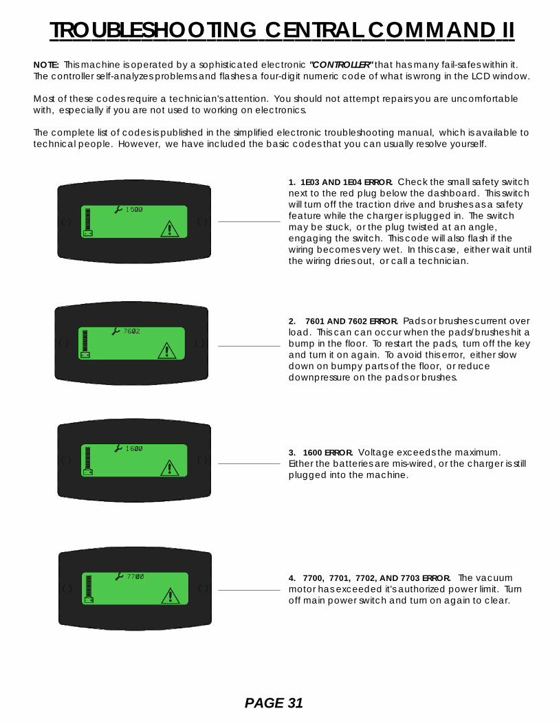
TROUBLESHOOTING CENTRAL COMMAND IINOTE: This machine is operated by a sophisticated electronic "CONTROLLER" that has many fail-safes within it.The controller self-analyzes problems and flashes a four-digit numeric code of what is wrong in the LCD window.
Most of these codes require a technician's attention. You should not attempt repairs you are uncomfortablewith, especially if you are not used to working on electronics.
The complete list of codes is published in the simplified electronic troubleshooting manual, which is available totechnical people. However, we have included the basic codes that you can usually resolve yourself.
1. 1E03 AND 1E04 ERROR. Check the small safety switchnext to the red plug below the dashboard. This switchwill turn off the traction drive and brushes as a safetyfeature while the charger is plugged in. The switchmay be stuck, or the plug twisted at an angle,engaging the switch. This code will also flash if thewiring becomes very wet. In this case, either wait untilthe wiring dries out, or call a technician.
2. 7601 AND 7602 ERROR. Pads or brushes current overload. This can can occur when the pads/brushes hit abump in the floor. To restart the pads, turn off the keyand turn it on again. To avoid this error, either slowdown on bumpy parts of the floor, or reducedownpressure on the pads or brushes.
3. 1600 ERROR. Voltage exceeds the maximum.Either the batteries are mis-wired, or the charger is stillplugged into the machine.
4. 7700, 7701, 7702, AND 7703 ERROR. The vacuummotor has exceeded it's authorized power limit. Turnoff main power switch and turn on again to clear.
PAGE 31
9. All other error codes. Turn off the main power switch and disconnect the positve battery cable from thebatteries for more than one minute (the time is needed to drain the controller's on-board capacitor).Reconnect the cables being sure they are tight; too loose will burn the batteries. If you overtighten the cablesyou can damage the battery's lead terminal. Try again.
10. If the problem cannot be solved by any of these remedie's call your local dealer's service department.
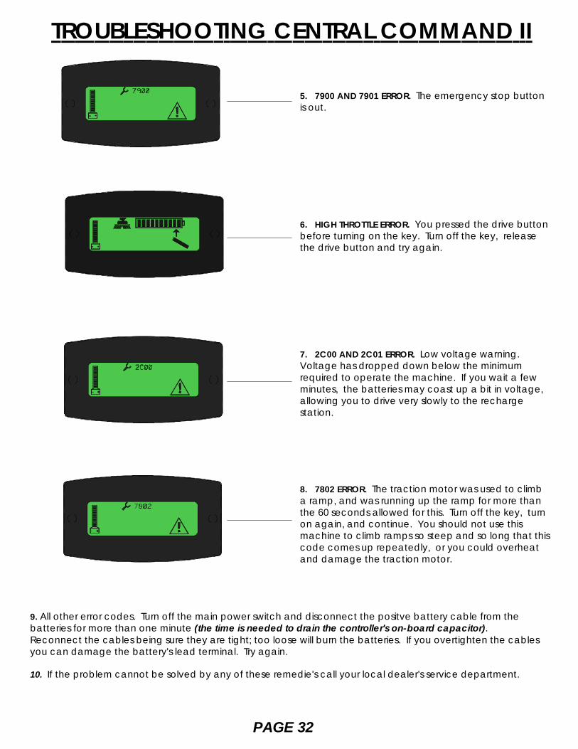
5. 7900 AND 7901 ERROR. The emergency stop buttonis out.
6. HIGH THROTTLE ERROR. You pressed the drive buttonbefore turning on the key. Turn off the key, releasethe drive button and try again.
7. 2C00 AND 2C01 ERROR. Low voltage warning.Voltage has dropped down below the minimumrequired to operate the machine. If you wait a fewminutes, the batteries may coast up a bit in voltage,allowing you to drive very slowly to the rechargestation.
8. 7802 ERROR. The traction motor was used to climba ramp, and was running up the ramp for more thanthe 60 seconds allowed for this. Turn off the key, turnon again, and continue. You should not use thismachine to climb ramps so steep and so long that thiscode comes up repeatedly, or you could overheatand damage the traction motor.
PAGE 32
TROUBLESHOOTING CENTRAL COMMAND II
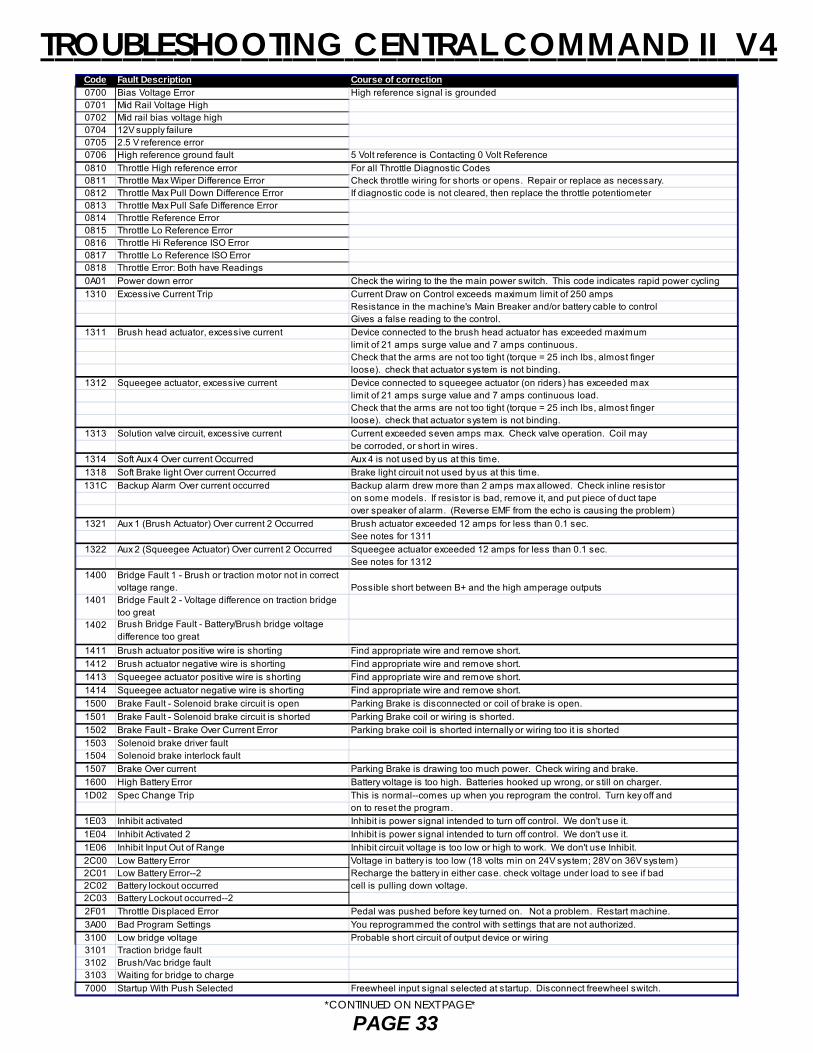
Code Fault Description Course of correction0700 Bias Voltage Error High reference signal is grounded0701 Mid Rail Voltage High0702 Mid rail bias voltage high0704 12V supply failure0705 2.5 V reference error0706 High reference ground fault 5 Volt reference is Contacting 0 Volt Reference0810 Throttle High reference error For all Throttle Diagnostic Codes0811 Throttle Max Wiper Difference Error Check throttle wiring for shorts or opens. Repair or replace as necessary.0812 Throttle Max Pull Down Difference Error If diagnostic code is not cleared, then replace the throttle potentiometer0813 Throttle Max Pull Safe Difference Error0814 Throttle Reference Error0815 Throttle Lo Reference Error0816 Throttle Hi Reference ISO Error0817 Throttle Lo Reference ISO Error0818 Throttle Error: Both have Readings0A01 Power down error Check the wiring to the the main power switch. This code indicates rapid power cycling1310 Excessive Current Trip Current Draw on Control exceeds maximum limit of 250 amps
Resistance in the machine's Main Breaker and/or battery cable to controlGives a false reading to the control.
1311 Brush head actuator, excessive current Device connected to the brush head actuator has exceeded maximumlimit of 21 amps surge value and 7 amps continuous.Check that the arms are not too tight (torque = 25 inch lbs, almost fingerloose). check that actuator system is not binding.
1312 Squeegee actuator, excessive current Device connected to squeegee actuator (on riders) has exceeded maxlimit of 21 amps surge value and 7 amps continuous load.Check that the arms are not too tight (torque = 25 inch lbs, almost fingerloose). check that actuator system is not binding.
1313 Solution valve circuit, excessive current Current exceeded seven amps max. Check valve operation. Coil maybe corroded, or short in wires.
1314 Soft Aux 4 Over current Occurred Aux 4 is not used by us at this time. 1318 Soft Brake light Over current Occurred Brake light circuit not used by us at this time.131C Backup Alarm Over current occurred Backup alarm drew more than 2 amps max allowed. Check inline resistor
on some models. If resistor is bad, remove it, and put piece of duct tapeover speaker of alarm. (Reverse EMF from the echo is causing the problem)
1321 Aux 1 (Brush Actuator) Over current 2 Occurred Brush actuator exceeded 12 amps for less than 0.1 sec.See notes for 1311
1322 Aux 2 (Squeegee Actuator) Over current 2 Occurred Squeegee actuator exceeded 12 amps for less than 0.1 sec.See notes for 1312
1400 Bridge Fault 1 - Brush or traction motor not in correct voltage range. Possible short between B+ and the high amperage outputs
1401 Bridge Fault 2 - Voltage difference on traction bridgetoo great
1402 Brush Bridge Fault - Battery/Brush bridge voltage difference too great
1411 Brush actuator positive wire is shorting Find appropriate wire and remove short.1412 Brush actuator negative wire is shorting Find appropriate wire and remove short.1413 Squeegee actuator positive wire is shorting Find appropriate wire and remove short.1414 Squeegee actuator negative wire is shorting Find appropriate wire and remove short.1500 Brake Fault - Solenoid brake circuit is open Parking Brake is disconnected or coil of brake is open.1501 Brake Fault - Solenoid brake circuit is shorted Parking Brake coil or wiring is shorted.1502 Brake Fault - Brake Over Current Error Parking brake coil is shorted internally or wiring too it is shorted1503 Solenoid brake driver fault1504 Solenoid brake interlock fault1507 Brake Over current Parking Brake is drawing too much power. Check wiring and brake.1600 High Battery Error Battery voltage is too high. Batteries hooked up wrong, or still on charger.1D02 Spec Change Trip This is normal--comes up when you reprogram the control. Turn key off and
on to reset the program.1E03 Inhibit activated Inhibit is power signal intended to turn off control. We don't use it.1E04 Inhibit Activated 2 Inhibit is power signal intended to turn off control. We don't use it.1E06 Inhibit Input Out of Range Inhibit circuit voltage is too low or high to work. We don't use Inhibit.2C00 Low Battery Error Voltage in battery is too low (18 volts min on 24V system; 28V on 36V system)2C01 Low Battery Error--2 Recharge the battery in either case. check voltage under load to see if bad2C02 Battery lockout occurred cell is pulling down voltage.2C03 Battery Lockout occurred--22F01 Throttle Displaced Error Pedal was pushed before key turned on. Not a problem. Restart machine.3A00 Bad Program Settings You reprogrammed the control with settings that are not authorized.3100 Low bridge voltage Probable short circuit of output device or wiring3101 Traction bridge fault3102 Brush/Vac bridge fault3103 Waiting for bridge to charge7000 Startup With Push Selected Freewheel input signal selected at startup. Disconnect freewheel switch.
PAGE 33
TROUBLESHOOTING CENTRAL COMMAND II V4
*CONTINUED ON NEXT PAGE*

7001 Push Activated in Drive Mode Freewheel input signal activated while driving. Disconnect freewheel switch.NOTE: As of this reading, we do not use Freewheel. This permits pushingmachine more easily by disconnecting traction motor from control.
7500 Throttle Comms Time Out Problem with LCD dash module or with wiring to it. Check and replace as necessary.7501 LCD Module settings corrupt Disconnect batteries and wait 2 minutes to reconnect7600 Brush motor not connected Check for open circuit7601 Soft Brush Current Fold back Too much load on brush motor. May be from hitting a bump or wire tangled in
brush drive mechanism. Possible wiring or brush motor short.7602 Soft Brush Current Foldback--2 Same as above.7603 Soft Brush Current Foldback--3 Same as above.7604 Brush Inhibit is on We do not use Brush Inhibit at this time.7605 Brush startup over current detection You may have started brushes on carpet or rubber or other high resistance material.
This may have stalled motor before actuator could react to lift brush head up.If chronic problem, call Factory to discuss reprogramming machine for application.
7700 Soft Vacuum Motor Disconnected Error Check wiring to vac motor. On 390, check wiring to Hella relay for vac motor7701 Vac Motor Current Fold back Too much amp load on vac circuit. Check wiring. May come from picking up
large column of water.7702 Soft Vacuum Current Foldback--2 Same as above7703 Soft Vacuum Current Foldback--3 Same as above7800 Traction Motor Fault No. 1 Check traction motor wiring and connectors. Include connector at steering pivot under
floor cover!7801 Traction Motor Over current Error Too much current due to bad motor or wiring to motor.7802 Soft Traction Motor in Fold back State Traction motor being overloaded, or ramp climbing that took longer than 60 seconds.
(Fold back means normal low amp setting to motor. There is one minute ramp climbingsurge that may be 4 times as high as the fold back rate).
7803 Motor Line Voltages Instability Timeout May be loose wire at motor or at control. Possible motor problem7880 Traction Speed Input Out of Range Throttle setting wrong for motor speed. Check throttle pot. and wiring.7900 Emergency Stop Error Emergency Stop Button is Actuated when you tried to move. Optional button.7901 Soft Belly Button Actuated Belly Button Switch activated. We don't use this.8000 Service Mode Service Timer Limits have been reached. We don't normally use them; they are
dealer option.9000 Brushes not fitted Check brush deck to make sure brushes are on, and on securely.0003 Possible terminal short in system For all of these Diagnostic Codes:0100 1. Turn off keyswitch and disconnect battery for two minutes, using your watch to 0204 measure time.0A01 2. When you reconnect battery, you must see a spark. This shows the control's 0B02 on-board capacitor has been discharged and has been refilled.1704 3. Restore the battery connection. Make sure battery cable is on tight before trying1705 machine or you could burn battery posts and cable. 1706 4. Turn on machine. If diagnostic code still shows, then replace the control.
TROUBLESHOOTING CENTRAL COMMAND II V4
PAGE 34
*CONTINUED FROM PREVIOUS PAGE*
TROUBLE SHOOTING
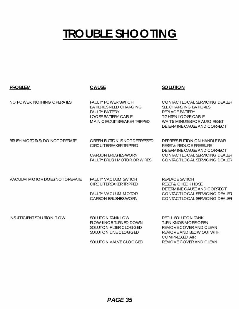
PROBLEM
NO POWER, NOTHING OPERATES
BRUSH MOTOR(S) DO NOT OPERATE
VACUUM MOTOR DOES NOT OPERATE
INSUFFICIENT SOLUTION FLOW
CAUSE
FAULTY POWER SWITCHBATTERIES NEED CHARGINGFAULTY BATTERYLOOSE BATTERY CABLEMAIN CIRCUIT BREAKER TRIPPED
GREEN BUTTON IS NOT DEPRESSEDCIRCUIT BREAKER TRIPPED
CARBON BRUSHES WORNFAULTY BRUSH MOTOR OR WIRES
FAULTY VACUUM SWITCHCIRCUIT BREAKER TRIPPED
FAULTY VACUUM MOTORCARBON BRUSHES WORN
SOLUTION TANK LOWFLOW KNOB TURNED DOWNSOLUTION FILTER CLOGGEDSOLUTION LINE CLOGGED
SOLUTION VALVE CLOGGED
SOLUTION
CONTACT LOCAL SERVICING DEALERSEE CHARGING BATTERIESREPLACE BATTERYTIGHTEN LOOSE CABLEWAIT 5 MINUTES FOR AUTO RESETDETERMINE CAUSE AND CORRECT
DEPRESS BUTTON ON HANDLE BARRESET & REDUCE PRESSUREDETERMINE CAUSE AND CORRECTCONTACT LOCAL SERVICING DEALERCONTACT LOCAL SERVICING DEALER
REPLACE SWITCHRESET & CHECK HOSEDETERMINE CAUSE AND CORRECTCONTACT LOCAL SERVICING DEALERCONTACT LOCAL SERVICING DEALER
REFILL SOLUTION TANKTURN KNOB MORE OPENREMOVE COVER AND CLEANREMOVE AND BLOW OUT WITHCOMPRESSED AIRREMOVE COVER AND CLEAN
PAGE 35
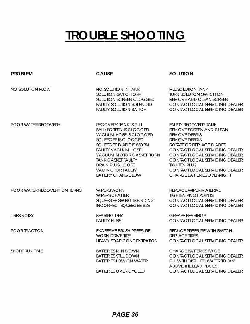
PROBLEM
NO SOLUTION FLOW
POOR WATER RECOVERY
POOR WATER RECOVERY ON TURNS
TIRES NOISY
POOR TRACTION
SHORT RUN TIME
CAUSE
NO SOLUTION IN TANKSOLUTION SWITCH OFFSOLUTION SCREEN CLOGGEDFAULTY SOLUTION SOLENOIDFAULTY SOLUTION SWITCH
RECOVERY TANK IS FULLBALL/SCREEN IS CLOGGEDVACUUM HOSE IS CLOGGEDSQUEEGEE IS CLOGGEDSQUEEGEE BLADE IS WORNFAULTY VACUUM HOSEVACUUM MOTOR GASKET TORNTANK GASKET FAULTYDRAIN PLUG LOOSEVAC MOTOR FAULTYBATTERY CHARGE LOW
WIPERS WORNWIPERS CHATTERSQUEEGEE SWING IS BINDINGINCORRECT SQUEEGEE SIZE
BEARING DRYFAULTY HUBS
EXCESSIVE BRUSH PRESSUREWORN DRIVE TIREHEAVY SOAP CONCENTRATION
BATTERIES RUN DOWNBATTERIES STILL DOWNBATTERIES LOW ON WATER
BATTERIES OVER CYCLED
SOLUTION
FILL SOLUTION TANKTURN SOLUTION SWITCH ONREMOVE AND CLEAN SCREENCONTACT LOCAL SERVICING DEALERCONTACT LOCAL SERVICING DEALER
EMPTY RECOVERY TANKREMOVE SCREEN AND CLEANREMOVE DEBRISREMOVE DEBRISROTATE OR REPLACE BLADESCONTACT LOCAL SERVICING DEALERCONTACT LOCAL SERVICING DEALERCONTACT LOCAL SERVICING DEALERTIGHTEN PLUGCONTACT LOCAL SERVICING DEALERCHARGE BATTERIES OVERNIGHT
REPLACE WIPER MATERIALTIGHTEN PIVOT POINTSCONTACT LOCAL SERVICING DEALERCONTACT LOCAL SERVICING DEALER
GREASE BEARINGSCONTACT LOCAL SERVICING DEALER
REDUCE PRESSURE WITH SWITCHREPLACE TIRESCONTACT LOCAL SERVICING DEALER
CHARGE BATTERIES TWICECONTACT LOCAL SERVICING DEALERFILL WITH DISTILLED WATER TO 3/4"ABOVE THE LEAD PLATESCONTACT LOCAL SERVICING DEALER
TROUBLE SHOOTING
PAGE 36

THIS PAGE INTENTIONALLY LEFT BLANK