Embed Size (px)
Citation preview
MAGNETO IGNITION SYSTEM
The magneto is mounted in the same way as a distributor, and is driven at half engine-speed from the camshaft. A rotating Ipagnet design is used and, in order to facilitate servicing, the contact breaker is of the standard pattern used in coil ignition distributors.
The coil consists of a laminated core, around which are wound the primary or low tension and the secondary or high tension windings. The high tension winding is brought out to a terminal stud, from which the connection to the rotating distributor arm is made by means of a contact spring in the coil cover and a short length of rubber-covered cable.
The engine drives the rotor, and by its rotation an alternating low tension current is induced in the primary winding. At the instant when this current is at or near a maximum, a lobe of the cam opens the contact breaker points, and a high voltage is induced in the secondary. At the same moment the rotor arm of the distributor connects the magneto to the sparking plug in the cylinder under compression, and the mixture is ignited.
The magneto has horizontal high tension connections, and is fitted with a centrifugal automatic timing control.
MAINTENANCE
In general, routine maintenance consists of cleaning, lubrication and the occasional adjustment of the contact breaker.
Take great care to prevent oil or grease getting on or near the contacts. ,
Every IOO running hours
Add thin machine oil through the oiler in the base to the level of the lubricator plug to lubricate the magneto shaft and the automatic timing control.
Note - The bearings are pre-lubricated and need no other lubrication.
Every zoo running hours
Note - Any necessity for over-frequent gap adjustment will usuallv be due to excessive wear of the heel of the contac; breaker lever, resulting from lack of cam lubrication.
Smear the cam with a little light grease. Place a spot of oil on the pivot on which the contact breaker lever works.
Thoroughly clean the magneto cap, inside and out, with a soft, dry cloth, paying particular attention to the spaces between the metal electrodes. Ensure that the small carbon brush moves freely in its holder.
Check the contacts for cleanliness and freedom from oil or grease. If they are burnt or blackened, clean them with fine emery cloth or a very fine carborundum stone and then wipe with a petrol-moistened cloth.
Cleaning is facilitated by removal of the moving contact. The contact breaker spring is slotted for this purpose.
4 After cleaning, check the contact breaker setting. Turn the engine by hand until the contacts show the maximum opening, whch should measure 0.010 in. to 0.012 in., i.e., a gauge of thls thickness should be a sliding fit between the contacts. If adjustment is necessary, keep the engine in the position giving maximum opening of the contacts and slacken the rwo screws securing the fixed contact plate. Move the plate until the gap is set to the thickness of the gauge. Tighten the screws firmly after adjustment.
5 Check the adjustment with other positions of the engine giving'maximum opening.
Testing in Position t o Locate Cause of Uneven Firing
Run the engine at a fairly fast idling speed.
Short circuit each plug in turn with the blade of an insulated screwdriver placed across the terminal to contact the cylinder head.
Short-circuiting the defective plug will cause no noticeable change in the running note. On the others, however, there will be a pronounced increase in roughness. Having thus located the defective cylinder, stop the engine and remove the cable from the sparking plug terminal.
Restart the engine and hold the end of the cable about & in, from the cylinder head. If sparking is strong and regular, the fault lies with the sparking plug, and it should be removed, cleaned and adjusted, or a replacement fitted. If, however, there is no spark, examine the cable from th? plug to the distributor for deterioration of the insulation, renewing the cable if the rubber is cracked or perished.
To connect a new cable to the magneto cap, cut the cable squarely to the required length. Loosen the securing screw from the inside of the cap,, push the cable into the cap as far as it will go, and tlghten the securing screw so that its point pierces right through the cable to make good contact with the core.
Clean and examine the magneto cap, ensuring that the carbon brush can move freely. If tracking has occurred, indicated by a thin black line on the cap, usually between two or more electrodes, a new cap must be fitted.
If the magneto has been replaced recently, check that it is correctly timed.
Testing in Position t o Locate Cause of Ignition Failure
1 Remove the magneto cap, and examine for dirt or oil, signs of tracking and condition of carbon brush. Examine the cable from the coil to the centre terminal of the cap for cracked or perished insulation, renewing if necessary.
ELECTRICAL
2 Lift off the rotor and check the contacts for cleanliness and correct gap setting.
Check the tension of the contact breaker spring. The correct value is 20 to 24 oz., measured at the contacts.
3 Disconnect tGe lead to the switch from the low-tension terminal on the magneto body, and turn the engine. If the magneto now functions normally, inspect the lead and switch to ensure that there is no evidence of short-circuit to earth.
Condenser
The condenser is secured to the contact breaker base by means of a clip, retaining screw and spring washer. Its P-nnecting strip is slotted to enable it to be lifted off the
ninal bolt.
The possible causes of condenser trouble, and the symptoms by which each may be recognised, are :-
(a) Open circuit, indicated by excessive burning at the contacts.
(b) Short circuit, indicated by complete failure of ignition and no sparking at contacts when the magneto is turned by hand.
(c) Abnormally low insulation resistance, indicated by poor low speed performance, when the condenser becomes heated after a period of running.
It should be noted that loose or dirty connections to the condenser will produce the same symptoms as (a), and that in the case of (c) the insulation resistance must fall to a very low value before ignition performance is appreciably affected.
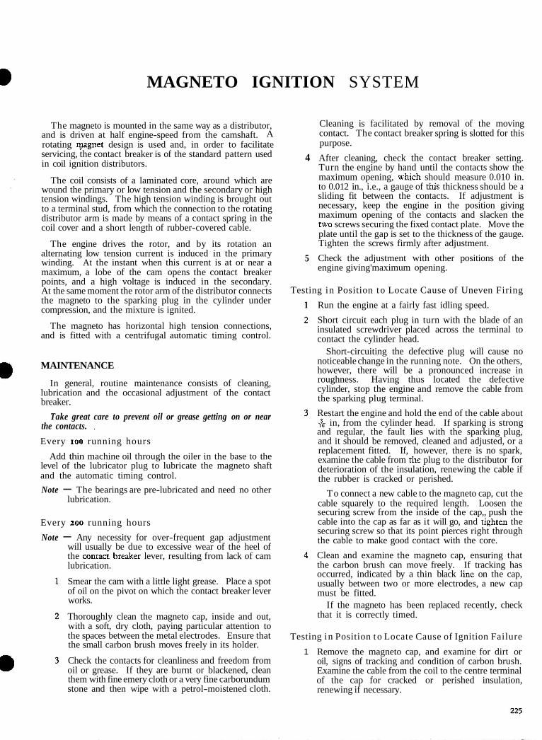
Fig. 264 Starting Position
Fig. 265 Normal Running Position
Star t ing Procedure
A manual control is incorporated and m u s t b e used f o r retarding the ignition for s tar t ing purposes.
I Pull out the spring-loaded manual advance and retard handle and turn it a half-turn (left- or right-hand) to the vertical position to retard the ignition. (See Figs. 264 and 265.)
2 Switch on the ignition and start the tractor. Return the handle to the horizontal position, as soon as the engine starts, to advance the ignition for normal running.
To Stop
Turn the ignition key to the " off" (vertical) position to earth " the primary circuit of the magneto and cut out the igni~ion.
To Adjust the Contact Breaker Points G a p
1 Unscrew the two thumb screws retaining the magneto cap and remove the cap.
2 Turn the engine so that the heel of the contact breaker is on the highest point of the cam.
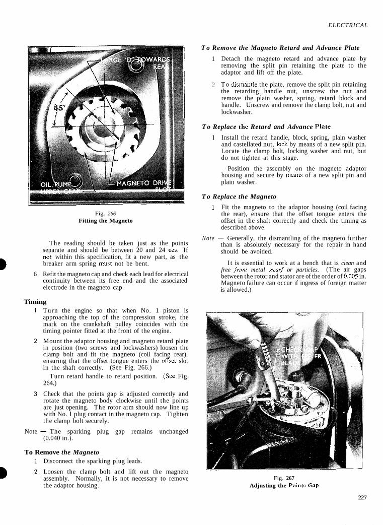
3 Slacken the locking screws securing the adjustable contact to the base and adjust the points gap to 0.010 in. to 0.012 in. (See Fig. 267.)
4 Tighten both locking screws and recheck the gap on - - all cam lobes.
5 Measure the contact breaker arm spring tension by pressing the hook of the scale AT/SV 12162 a~ainst
a the breaker arm adjacent to the contact point.-
ELECTRICAL
T o Remove the Magneto Retard and Advance Plate
Fig. 266 Fitting the Magneto
The reading should be taken just as the points senarate and should be between 20 and 24 02s. If n i t within this specification, fit a new part, as the breaker arm spring must not be bent.
6 Refit the magneto cap and check each lead for electrical continuity between its free end and the associated electrode in the magneto cap.
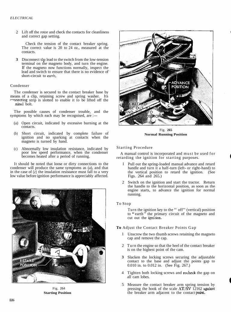
Timing 1 Turn the engine so that when No. 1 piston is
approaching the top of the compression stroke, the mark on the crankshaft pulley coincides with the timing pointer fitted at the front of the engine.
2 Mount the adaptor housing and magneto retard plate in position (two screws and lockwashers) loosen the clamp bolt and fit the magneto (coil facing rear), ensuring that the offset tongue enters the oEsct slot in the shaft correctly. (See Fig. 266.)
Turn retard handle to retard position. (Sce Fig. 264.)
3 Check that the points gap is adjusted correctly and rotate the magneto body clockwise until the points are just opening. The rotor arm should now line up with No. l plug contact in the magneto cap. Tighten the clamp bolt securely.
Note - The sparking plug gap remains unchanged (0.040 in.).
To Remove the Magneto Disconnect the sparking plug leads.
Loosen the clamp bolt and lift out the magneto assembly. Normally, it is not necessary to remove the adaptor housing.
1 Detach the magneto retard and advance plate by removing the split pin retaining the plate to the adaptor and lift off the plate.
2 T o dismantle the plate, remove the split pin retaining the retarding handle nut, unscrew the nut and remove the plain washer, spring, retard block and handle. Unscrew and remove the clamp bolt, nut and lockwasher.
T o Replace the Retard and Advance Plate
l Install the retard handle, block, spring, plain washer and castellated nut, lcck by means of a new split pin. Locate the clamp bolt, locking washer and nut, but do not tighten at this stage.
Position the assembly on the magneto adaptor housing and secure by means of a new split pin and plain washer.
T o Replace the Magneto
1 Fit the magneto to the adaptor housing (coil facing the rear), ensure that the offset tongue enters the offset in the shaft correctly and check the timing as described above.
Note - Generally, the dismantling of the magneto further than is absolutely necessary for the repair in hand should be avoided.
I t is essential to work at a bench that is clean and free from metal swurJ or particles. (The air gaps between the rotor and stator are of the order of 0.005 in. Magneto failure can occur if ingress of foreign matter is allowed.)
Fig. 267 Adjusting the Points Gztp
227
ELECTRICAL
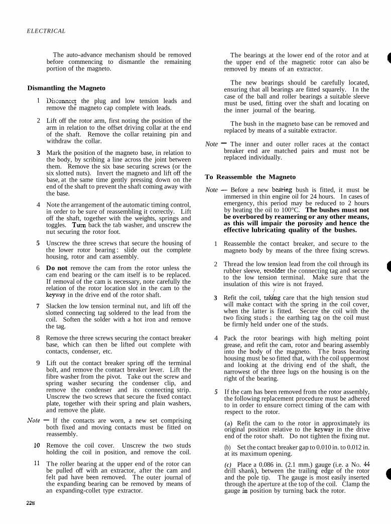
The auto-advance mechanism should be removed before commencing to dismantle the remaining portion of the magneto.
Dismantling the Magneto
1 Disconnec; the plug and low tension leads and remove the magneto cap complete with leads.
2 Lift off the rotor arm, first noting the position of the arm in relation to the offset driving collar at the end of the shaft. Remove the collar retaining pin and withdraw the collar.
3 Mark the position of the magneto base, in relation to the body, by scribing a line across the joint between them. Remove the six base securing screws (or the six slotted nuts). Invert the magneto and lift off the base, at the same time gently pressing down on the end of the shaft to prevent the shaft coming away with the base.
4 Note the arrangement of the automatic timing control, in order to be sure of reassembling it correctly. Lift off the shaft, together with the weights, springs and toggles. Turn back the tab washer, and unscrew the nut securing the rotor foot.
5 Unscrew the three screws that secure the housing of the lower rotor bearing : slide out the complete housing, rotor and cam assembly.
6 Do not remove the cam from the rotor unless the cam end bearing or the cam itself is to be replaced. If removal of the cam is necessary, note carefully the relation of the rotor location slot in the cam to the keyway in the drive end of the rotor shaft.
7 Slacken the low tension terminal nut, and lift off the slotted connecting tag soldered to the lead from the coil. Soften the solder with a hot iron and remove the tag.
8 Remove the three screws securing the contact breaker base, which can then be lifted out complete with contacts, condenser, etc.
9 Lift out the contact breaker spring off the terminal bolt, and remove the contact breaker lever. Lift the fibre washer from the pivot. Take out the screw and spring washer securing the condenser clip, and remove the condenser and its connecting strip. Unscrew the two screws that secure the fixed contact plate, together with their spring and plain washers, and remove the plate.
LVote - If the contacts are worn, a new set comprising both fixed and moving contacts must be fitted on reassembly.
10 Remove the coil cover. Unscrew the two studs holding the coil in position, and remove the coil.
11 The roller bearing at the upper end of the rotor can be pulled off with an extractor, after the cam and felt pad have been removed. The outer journal of the expanding bearing can be removed by means of an expanding-collet type extractor.
The bearings at the lower end of the rotor and at the upper end of the magnetic rotor can also be removed by means of an extractor.
4 The new bearings should be carefully located,
ensuring that all bearings are fitted squarely. In the case of the ball and roller bearings a suitable sleeve must be used, fitting over the shaft and locating on the inner journal of the bearing.
The bush in the magneto base can be removed and replaced by means of a suitable extractor.
Note - The inner and outer roller races at the contact breaker end are matched pairs and must not be replaced individually.
To Reassemble the Magneto
Note - Before a new bedring bush is fitted, it must be immersed in thin engine oil for 24 hours. In cases of emergency, this period may be reduced to 2 hours by heating the oil to 100°C. The bushes must not be overbored by reamering or any other means, as this will impair the porosity and hence the effective lubricating quality of the bushes.
1 Reassemble the contact breaker, and secure to the magneto body by means of the three fixing screws.
2 Thread the low tension lead from the coil through its rubber sleeve, resolder the connecting tag and secure to the low tension terminal. Make sure that the insulation of this wire is not frayed.
l
3 Refit the coil, takiing care that the high tension stud will make contact with the spring in the coil cover, when the latter is fitted. Secure the coil with the two fixing studs ; the earthing tag on the coil must be firmly held under one of the studs.
4 Pack the rotor bearings with high melting point grease, and refit the cam, rotor and bearing assembly into the body of the magneto. The brass bearing housing must be so fitted that, with the coil uppermost and looking at the driving end of the shaft, the narrowest of the three lugs on the housing is on the right of the bearing.
5 If the cam has been removed from the rotor assembly, the following replacement procedure must be adhered to in order to ensure correct timing of the cam with respect to the rotor.
(a) Refit the cam to the rotor in approximately its original position relative to the keyway in the drive end of the rotor shaft. Do not tighten the fixing nut.
(b) Set the contact breaker gap to 0.010 in. to 0.012 in. at its maximum opening.
(c ) Place a 0.086 in. (2.1 mm.) gauge (i.e. a NO. 44 drill shank), between the trailing edge of the rotor and the pole tip. The gauge is most easily inserted through the aperture at the top of the coil. Clamp the gauge h position by turning back the rotor.
ELECTRICAL
CONTACT BREAKER CAM
WASHER
FELT (LARGE) DISHED WASHER- MAGNETO CAP
MAGNE ROTOR
BEARING
CONDENSOR CONTACT BREAKER SPRING
BAKELITE BUSH
/-INSULATING PLATE
INSULATING WASHER CONTACT PLAIN WASHER BREAKER BASE
NUT NUT
EEVE
W A S H E R - MAGNETO BODY
DRIVING F 0 0
TAB WASHER
AUTO ADVANCE WEIGHT TOGGLE
LUBRICATOR
T A B WASHER
MAGNETO BASE
TARD PLATE
CLAMP BOLT
ADAPTOR HOUSING
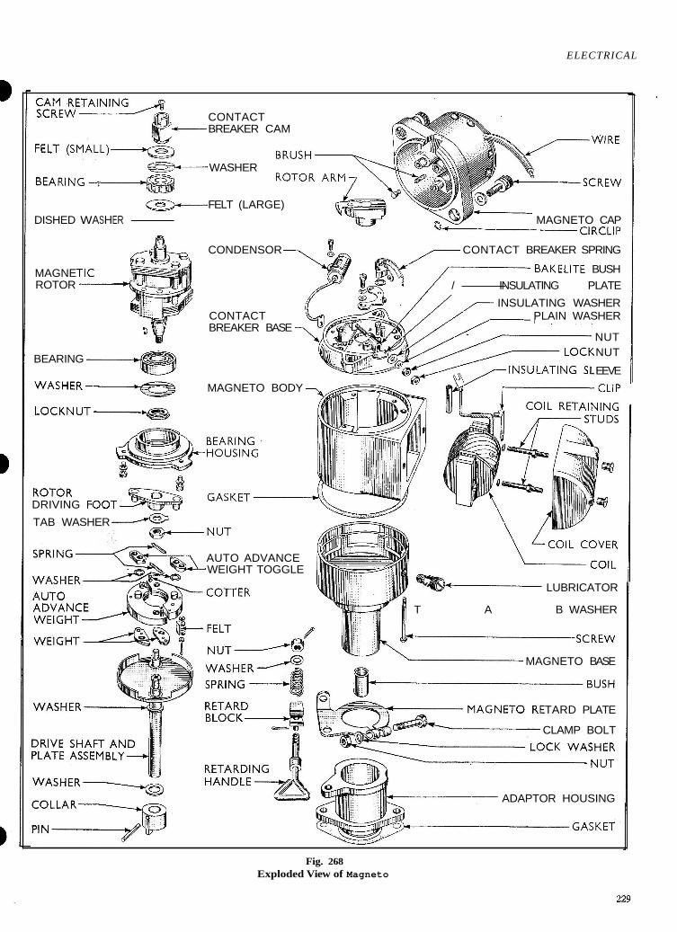
Fig. 268 Exploded View of Magneto
ELECTRICAL
6 Adjust the cam until the contacts are just about to break, i.e. the slightest movement of the rotor in the correct direction of rotation results in the contacts opening.
Lightly tap the cam home on its taper and tighten the fixing nut and lock nut.
7
Note - This must always be done before reassembling the automatic timing control.
7 Fit the rotor driving foot on to the shaft, taking care that it does not ride over the key, and secure with the tab washer and nut.
8 Assemble the main weights, auxiliary weights, springs and toggles on to the action plate. See that the brass washers are in position under the toggles.
9 Support the magneto in an inverted position, and # engage the pins on the rotor foot with the holes in the toggles. Place the fibre washer over the shaft.
10 Place the base over the shaft, and press into position, taking care that the reference marks scribed across the joint now coincide. Fit the six fixing screws and tighten down securely.
11 Refit the coil cover, rotor arm and magneto cap.
12 Locate the offset driving collar in position and secure by means of the pin, peen over the end to retain in position.
Note - When fitting the collar, great care must be taken that the driving shaft is not forced endways. A tapped hole is provided in the end of the shaft, so that by inserting a bolt the shaft can be supported while driving on the collar.
SPECIFICATION AND REPAIR DATA
Firing angles . . . . . . 0°, 90°, 180°, 270" + 1"
Contact breaker open period . . . . . . 55" + 2"
Contact breaker closed period . . . . 35" i 2"
Contact breaker gap . . . . . . 0.010 in. to 0.012 in.
Contact breaker spring tension, measured at contacts : 20 to 24 ozs.
Condenser capacity . . . . . . 0.2 microfarad
Direction of rotation : Anti-clockwise (viewed from drive end)
Maximum range . . . . . . . . 14"-16"
Springs . . . . . . . . 488232 (2 off)
High speed test : no missing must occur at 3,000 r.p.m., using an 8 kV. rotary gap.
Low speed test : regular sparking must occur at 45-60 r.p.m. on a 5.5 mm. 3 point gap. 45 r.p.m. is the standard test figure for a new magneto. In service, allowance should be made for depreciation.
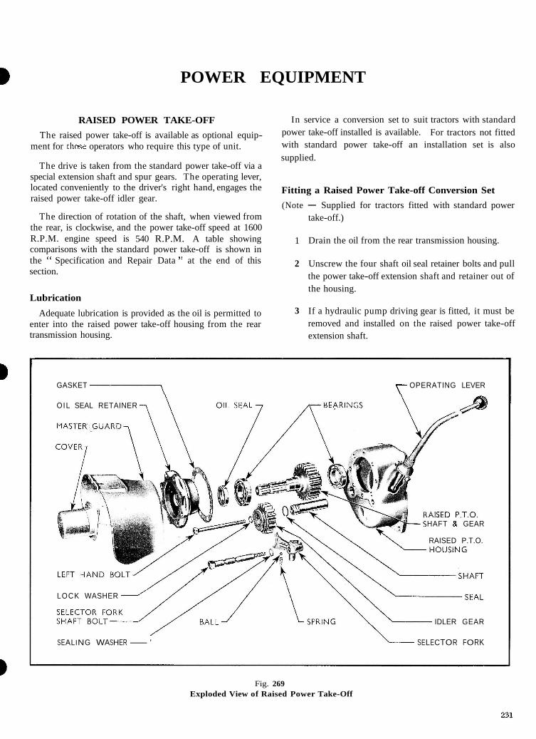
POWER EQUIPMENT
RAISED POWER TAKE-OFF
The raised power take-off is available as optional equip- ment for thme operators who require this type of unit.
The drive is taken from the standard power take-off via a special extension shaft and spur gears. The operating lever, located conveniently to the driver's right hand, engages the raised power take-off idler gear.
The direction of rotation of the shaft, when viewed from the rear, is clockwise, and the power take-off speed at 1600 R.P.M. engine speed is 540 R.P.M. A table showing comparisons with the standard power take-off is shown in the " Specification and Repair Data " at the end of this section.
Lubrication
Adequate lubrication is provided as the oil is permitted to enter into the raised power take-off housing from the rear transmission housing.
In service a conversion set to suit tractors with standard power take-off installed is available. For tractors not fitted with standard power take-off an installation set is also supplied.
Fitting a Raised Power Take-off Conversion Set
(Note - Supplied for tractors fitted with standard power take-off.)
1 Drain the oil from the rear transmission housing.
2 Unscrew the four shaft oil seal retainer bolts and pull the power take-off extension shaft and retainer out of the housing.
3 If a hydraulic pump driving gear is fitted, it must be removed and installed on the raised power take-off extension shaft.
GASKET y- OPERATING LEVER
OIL SEAL RETAINER
HAFT & GEAR
RAISED P.T.O.
LOCK WASHER
IDLER GEAR
SEALING WASHER-' L SELECTOR FORK
Fig. 269 Exploded View of Raised Power Take-Off
POWER EQUIPMENT
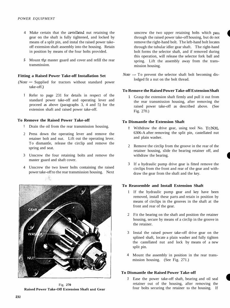
4 Make certain that the castel!ated nut retaining the gear .on the shaft is fully tightened, and locked by means of a split pin, and instal the raised power take- off extension shaft assembly into the housing. Retain in position by means of the four bolts provided.
5 Mount tbe master guard and cover and refill the rear transmission.
Fitting a Raised Power Take-off Installation Set
(Note - Supplied for tractors without standard power take-off .)
1 Refer to page 231 for details in respect of the standard power take-off and operating lever and proceed as above (paragraphs 3, 4 and 5) for the extension shaft and raised power take-off.
To Remove the Raised Power Take-off
1 Drain the oil from the rear transmission housing.
2 Press down the operating lever and remove the retainer bolt and nut. Lift out the operating lever. To dismantle, release the circlip and remove the spring and seat.
3 Unscrew the four retaining bolts and remove the master guard and shaft cover.
4 Unscrew the two lower bolts containing the raised power take-off to the rear transmission housing. Next
Fig. 270 Raised Power Take-Off Extension Shaft and Gear
unscrew the two upper retaining bolts which pass through the raised power take-off housing, but do not remove the right-hand bolt. The left-hand bolt locates
a through the tubular idler gear shaft. The right-hand bolt forms the selector shaft, and if removed during this operation, will release the selector fork ball and spring. Lift the assembly away from the trans- mission housing.
Note -- To prevent the selector shaft bolt becoming dis- lodged fit a nut on the bolt thread.
To Remove the Raised Power Take-off Extension Shaft
1 Grasp the extension shaft firmly and pull it out from the rear transmission housing, after removing the raised power take-off as described above. (See Fig. 270.)
To Dismantle the Extension Shaft
1 Withdraw the drive gear, using tool No. Tr/NM. 6306-A after removing the split pin, castellated nut and plain washer.
2 Remove the circlip from the groove in the rear of the retainer housing, slide the bearing retainer off, and withdraw the bearing.
3 If a hydraulic pump drive gear is fitted remove the circlips from the front and rear of the gear and with- draw the gear from the shaft and the key.
To Reassemble and Install Extension Shaft
1 If the hydraulic pump gear and key have been removed, install these parts and retain in position by means of circlips in the grooves in the shaft at the front and rear of the gear.
2 Fit the bearing on the shaft and position the retainer housing, secure by means of a circlip in the groove in the retainer.
3 Instal the raised power take-off drive gear on the splined shaft, locate a plain washer and fully tighten the castellated nut and lock by means of a new split pin.
4 Mount the assembly in position in the rear trans- mission housing. (See Fig. 271.)
To Dismantle the Raised Power Take-off
1 Ease the power take-off shaft, bearing and oil seal retainer out of the housing, after removing the four bolts securing the retainer to the housing. If

POWER EQUIPMENT
necessary, extract the oil seal from the retamer and fit a new seal with lip towards the housing. The two bearings may now be withdrawn in the normal manner and new parts fitted.
3 Carefully withdraw the selector fork shaft bolt (pr~viously left loose, when removing the raised pcwer take-off so that the ball and spring are not lost). The fork may now be removed from the housing.
3 Drive the tubular shaft out of the rear of the housing, supporting the idler gear during this operation.
To Reassemble and Replace the Raised Power Take-off
1 Position the idler gear, with the fork slot to the rear, locate the tubulzr shaft with a new oil sealing ring in the groove, and gently drive it home against the stop in the housing with the flat, at the outer end, positioned correctly to accommodate the oil seal retainer housing.
2 Locate the selector fork in the gear, position the spring and ball in the seat in the fork, gently holding the ball down from the front with a suitable tool and enter the shaft bolt (and sealing washer) from the rear. The shaft bolt is provided with a lead-in to facilitate assembly.
Note - To avoid losing the ball and spring take care that the shaft bolt is not now withdrawn from the housing.
3 Mount the raised power take-off assembly (with a - ,
new gasket) to the rear transmission housing and securely tighten the four retaining bolts (and washers).
Note - Spring lockwashers are fitted to the tubular idler gear shaft bolt and the two lower retaining bolts. A special sealing washer is fitted behind the head of the selector fork shaft bolt.
Instal and press down the operating lever in the neck of the housing, ensuring that it is engaged with the selector fork and retained by means of the bolt, lock- washer and nut.
Instal the power take-off shaft and oil seal retainer, with a new gasket, making certain that the flat of the housing coincides with the flat on the idler gear shaft. Secure by means of the four bolts and lockwashers.
Mount the master guard and cover in position using four bolts and lockwashers provided.
Refill the rear transmission housing with the correct grade and quantity of lubricant.
POWER TAKE-OFF
The power take-off supplied as optional equipment is fitted in the base of the front and the rear transmission housings, and is driven by the primary lower shaft gear and power take-off gear.
The power take-off extension shaft extends through the rear of the rear axle housing, a cover and shield is provided over the splined end of the shaft.
The power take-off is controlled by a lever which is mounted to the gear box selector plate, on the left-hand side of the tractor. Rearward movement of the lever engages the drive, which also actuates the hydraulic pump.
For details of the raised power take-off see pages 231 and 232.
Removing the Power Take-off and Extension Shaft
1 Drain the oil from the gearbox and the rear axle (see appropriate sections).
2 Remove the power take-off extension shaft master guard and cover (three bolts). Unscrew the four shaft oil seal retainer bolts and pull the shaft out of the housing.
3 Disconnect the operating lever (left-hand side of the tractor), and remove the selector housing (four bolts).
Fig. 271 Raised Power Take-Off
POWER EQUIPMENT
4 Unscrew the six bolts securing the power take-off to the base of the gearbox housing and remove the power take-off. Remove the rubber oil seal from the end of the housing.
5 Remove the hydraulic pump gear retaining circlip and press .?the gear off the shaft and key.
T o Replace the Power Take-off Extension Shaft
1 Locate the hydraulic pump gear to the shaft and key, fit the front and rear circlips to retain in position.
2 Assemble a ncw oilsseal in the retainer, fit the bearing on the shaft and position the oil seal and retainer. Secure by means of the circlip in the groove in the retainer.
3 Mount in position in the rear axle, using a new gasket between the retainer and axle housing. Tighten up thoroughly the four screws and lock- washers and fit the master guard and cover.
Dismantling the Power Take-off Extension Shaf t
1 Remove the hydraulic pump gear front circlip and draw the gear off the key and shaft.
2 Remove the bearing circlip and tap the oil seal retainer off the splined end of the shaft. The bearing is retained to the shaft by a collar that is shrunk in position. This collar must be removed if it is desired to withdraw the bearing. Remove the oil seal from the retainer.
To Remove the Power Take-off
1 Drain the oil from the gearbox and the rear axle.
2 Remove the power take-off extension shaft shield and cover (three bolts). Unscrew the four shaft oil seal retainer bolts, and pull the shaft and retainer out of the housing.
3 Disconnect the operating lever and remove the selector housing.
4 Remove the power take-off from the base of the gear. box, after unscrewing the six securing bolts. Remove the rubber oil seal from the end of the housing.
To Dismantle the Power Take-off
1 Remove the split pin retaining the idling gear shaft in the lugs of the housing, push out the shafi which will release the idler gear.
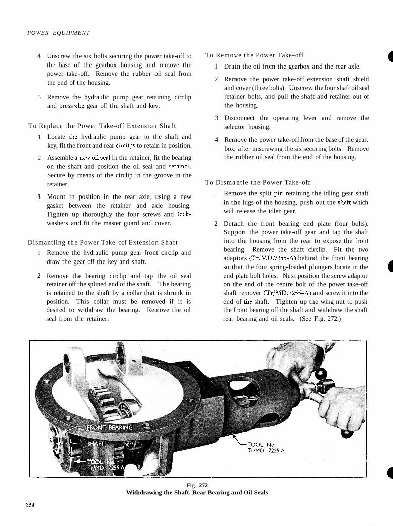
2 Detach the front bearing end plate (four bolts). Support the power take-off gear and tap the shaft into the housing from the rear to expose the front bearing. Remove the shaft circlip. Fit the two adaptors (TrlMD.7255-A) behind the front bearing so that the four spring-loaded plungers locate in the (I end plate bolt holes. Next position the screw adaptor on the end of the centre bolt of the power take-off shaft remover (TrIMD.7255-A) and screw it into the end of the shaft. Tighten up the wing nut to push the front bearing off the shaft and withdraw the shaft rear bearing and oil seals. (See Fig. 272.)
Fig. 272 Withdrawing the Shaft, Rear Bearing and Oil Seals
POWER EQUIPMENT
3 Remove the shaft rear bearing circlip and press off the bearing, using the tool numbered Tr/D.7006. Detach the circlip from the groove in the front bearing and lift out the power take-off gear.
To Reassemble the Power Take-off
1 Lo&te the front bearing and fit the circlip in the groove to retain it in position. Place the dummy end plate (TrID.77012) in front of the bearing and stand the housing on the plate.
2 Position the power take-off gear, with the selector fork upwards, and press the bearing on to the shaft using the tool TrID.7006. Fit the circlip and enter the shaft into the gear splines and tap into position into the lower bearing.
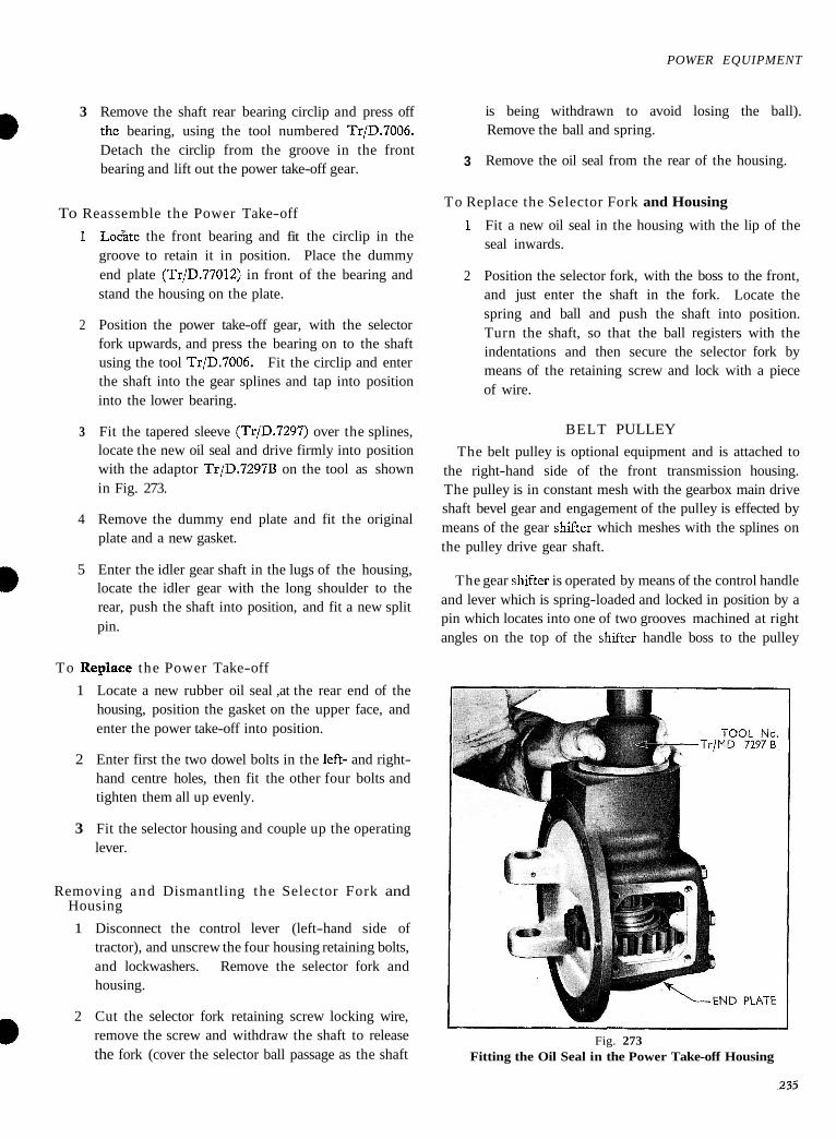
3 Fit the tapered sleeve (TrlD.7297) over the splines, locate the new oil seal and drive firmly into position with the adaptor TrID.7297B on the tool as shown in Fig. 273.
4 Remove the dummy end plate and fit the original plate and a new gasket.
5 Enter the idler gear shaft in the lugs of the housing, locate the idler gear with the long shoulder to the rear, push the shaft into position, and fit a new split pin.
To Replace the Power Take-off
1 Locate a new rubber oil seal ,at the rear end of the housing, position the gasket on the upper face, and enter the power take-off into position.
2 Enter first the two dowel bolts in the left- and right- hand centre holes, then fit the other four bolts and tighten them all up evenly.
3 Fit the selector housing and couple up the operating lever.
Removing and Dismantling the Selector Fork and Housing
1 Disconnect the control lever (left-hand side of tractor), and unscrew the four housing retaining bolts, and lockwashers. Remove the selector fork and housing.
a 2 Cut the selector fork retaining screw locking wire, remove the screw and withdraw the shaft to release the fork (cover the selector ball passage as the shaft
is being withdrawn to avoid losing the ball). Remove the ball and spring.
3 Remove the oil seal from the rear of the housing.
To Replace the Selector Fork and Housing
1 Fit a new oil seal in the housing with the lip of the seal inwards.
2 Position the selector fork, with the boss to the front, and just enter the shaft in the fork. Locate the spring and ball and push the shaft into position. Turn the shaft, so that the ball registers with the indentations and then secure the selector fork by means of the retaining screw and lock with a piece of wire.
BELT PULLEY
The belt pulley is optional equipment and is attached to the right-hand side of the front transmission housing. The pulley is in constant mesh with the gearbox main drive shaft bevel gear and engagement of the pulley is effected by means of the gear shifter which meshes with the splines on the pulley drive gear shaft.
The gear shifter is operated by means of the control handle and lever which is spring-loaded and locked in position by a pin which locates into one of two grooves machined at right angles on the top of the shifter handle boss to the pulley
Fig. 273 Fitting the Oil Seal in the Power Take-off Housing
POWER EQUIPMENT
housing. This method reduces the number of moving parts to a minimum and proviaes a secure drive either in, or out of, engagemend and avoids the possibility of it shifting due to vibration.
Lubrication ?
Sufficient lubrication is provided by the front transmission lubricant.
To Remove the Belt Pulley
1 Unscrew the two cover retaining bolts and remove the cover.
2 Unscrew the six retainer bolts and lift the pulley assembly and cover from the front transmission housing.
To Replace the Belt Pulley
1 Position a gasket on the pulley housing and enter the assembly in the mounting provided on the right-hand side of the front transmission housing. Normally, one gasket is sufficient to pravide sufficient backlash. Secure the pulley to the housing by means of the six retainer bolts.
2 Mount the cover in position and secure by the two retaining bolts.
On starting the tractor the pulley, when engaged under load, should operate without any whining or grinding noise.
To Dismantle the Belt Pulley
1 Disconnect the control handle from the lever by removing the split pin and cotter pin at the base of the handle.
2 Remove the split pin retaining the castellated nut on the end of the drive shaft, unscrew the nut and remove the outer washer. Using two of the bolts retaining the pulley to the front transmission housing, withdraw the splined bush from the centre of the pulley by screwing the bolts in the tapped holes in the splined bush. Tighten them up alternately, a little at a time, during this operation.
3 Pull the pulley from the drive shaft.
4 Withdraw the drive shaft assembly and remove the drive gear shifter.
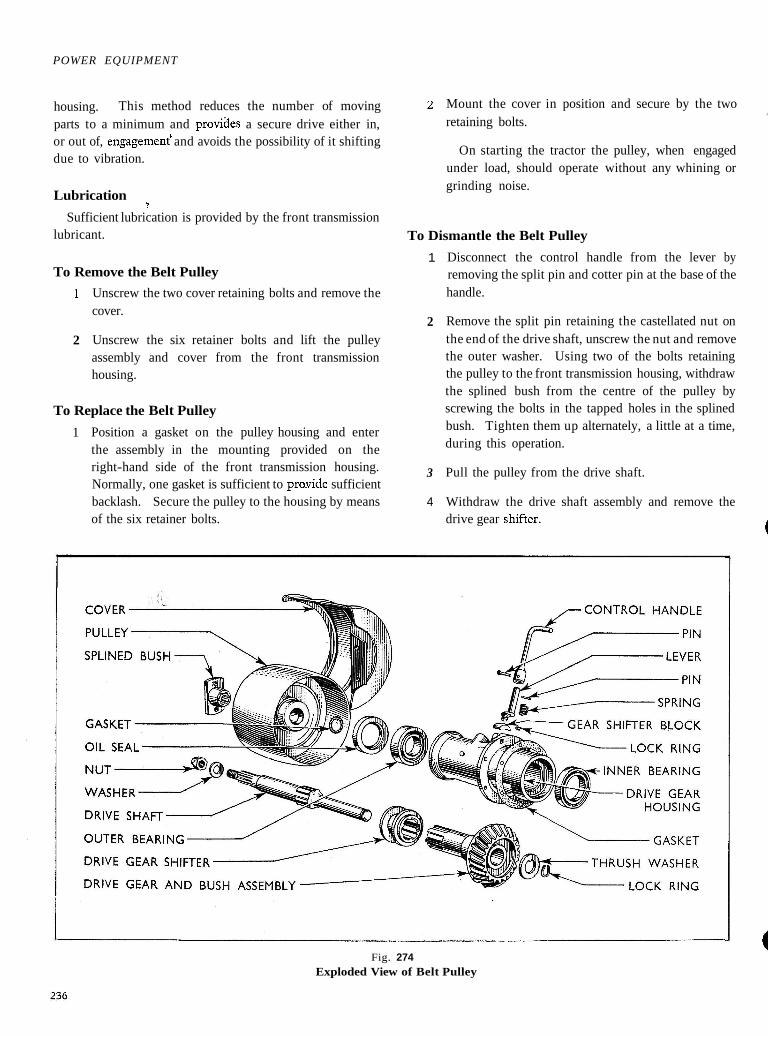
Fig. 274 Exploded View of Belt Pulley
POWER EQUIPMENT
TO dismantle the drive shaft assembly, remove the 3
lock ring from the end of the shaft, lift off the thrust washer and slide the drive shaft out of the drive gear.
5 Drive out the lever retaining groove pin from the lower 4 hole in the shaft and remove the lever and spring. To dihantle the block from the lever, drive the lever out of the block and remove the lock ring.
5
6 Remove the oil seal from the outer end of the housing.
7 Withdraw the inner and outer bearings, using suitable 6
equipment.
'To Assemble the Belt Pulley 7
1 Press the inner bearing in the housing.
2 Locate the lock ring in the groove in the end of the control handle lever and press the gear shift block on to the lever to engage the lock ring. Position the spring on the lever and enter the assembly through
Position the drive shaft in the drive gear and bush assembly and locate the thrust washer on the end of the shaft. Secure by means of the lock ring in the groove on the shaft.
Install the d r i~e '~ea r ahifter in position in the housing and enter the drive shaft assembly through the splines of the drive gear shifter.
Press on the outer bearing and then the oil seal (lip towards bearing) and locate the small gasket on the end of the shaft.
Position the pulley hub on the shaft, locate the outer washer and press on the splined bush retainer. Secure by means of the castellated nut which must be fully tightened and locked with a new split pin.
Install the control handle (facing rearwards) on the lever and retain by means of the cotter pin and split pin.
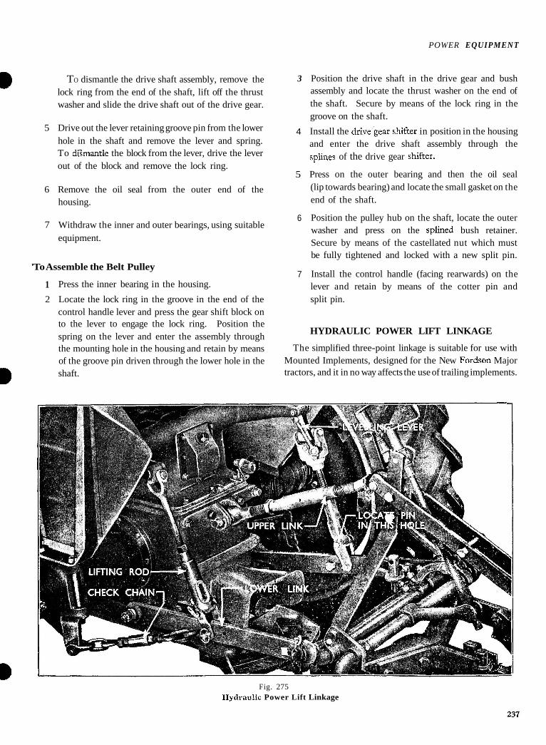
HYDRAULIC POWER LIFT LINKAGE
the mounting hole in the housing and retain by means The simplified three-point linkage is suitable for use with of the groove pin driven through the lower hole in the Mounted Implements, designed for the New Fordson Major shaft. tractors, and it in no way affects the use of trailing implements.
Fig. 275 Hydrau!ic Power Lift Linkage
P O V E R EQUIPMENT
All the necessary adjustments are easy to make, and include turnbuckle-type check chains to stabilise row-crop implements, and an adjustable top link which controls the pitch of Mounted Implements. Fixed and telescopic positions are provided on the lift and levelling rods, the latter ihcorporates a simple control for adjusting the level of mounted equipment.
The linkage (gee Fig. 275) plays a very important part in the successful working of the implement, and the operator must be fully conversant with the various positions in whict it may be used. I t must be understood that the linkage has been designed for any types of implements, and therefore some of the following information will not be applicable to every implement, but, nevertheless, it has been necessary to mention it.
The Hydraulic Power Lift Linkage comprises one adjustable upper link, two lower links, one lifting rod, one lifting link and levelling box assembly, two check chains, together with the necessary mounting brackets.
The upper and lower links are fitted with self-aligning ball sockets at each end. The ball sockets must not be lubricated, otherwise undue wear will result.
In addition to the linkage, a safety chain is provided for connecting the two lower links together when the implement is detached, to prevent the lower links striking the rear wheel.
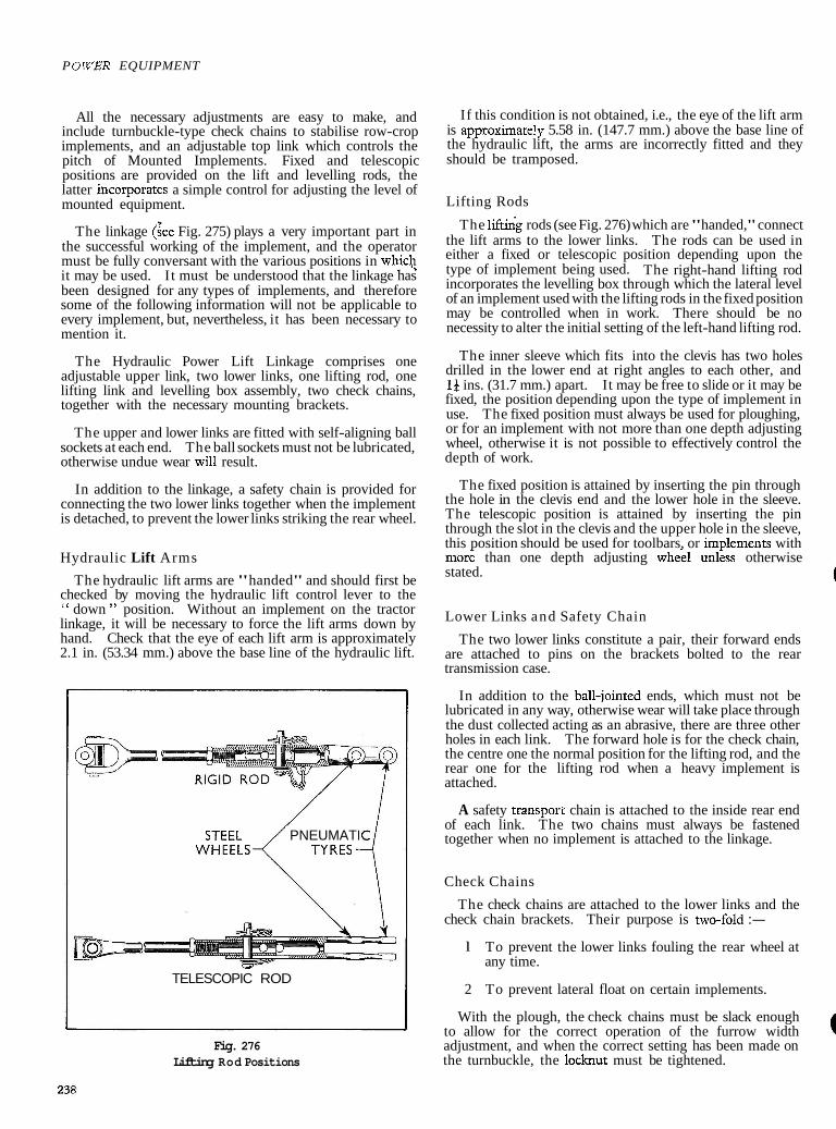
Hydraulic Lift Arms
The hydraulic lift arms are "handed" and should first be checked by moving the hydraulic lift control lever to the " down " position. Without an implement on the tractor linkage, it will be necessary to force the lift arms down by hand. Check that the eye of each lift arm is approximately 2.1 in. (53.34 mm.) above the base line of the hydraulic lift.
PNEUMATIC 1 TELESCOPIC ROD
Fig. 276 Lifting Rod Positions
If this condition is not obtained, i.e., the eye of the lift arm is approximate!^ 5.58 in. (147.7 mm.) above the base line of the hydraulic lift, the arms are incorrectly fitted and they
a should be tramposed.
Lifting Rods
The lifting rods (see Fig. 276) which are "handed," connect the lift arms to the lower links. The rods can be used in either a fixed or telescopic position depending upon the type of implement being used. The right-hand lifting rod incorporates the levelling box through which the lateral level of an implement used with the lifting rods in the fixed position may be controlled when in work. There should be no necessity to alter the initial setting of the left-hand lifting rod.
The inner sleeve which fits into the clevis has two holes drilled in the lower end at right angles to each other, and 19 ins. (31.7 mm.) apart. It may be free to slide or it may be fixed, the position depending upon the type of implement in use. The fixed position must always be used for ploughing, or for an implement with not more than one depth adjusting wheel, otherwise it is not possible to effectively control the depth of work.
The fixed position is attained by inserting the pin through the hole in the clevis end and the lower hole in the sleeve. The telescopic position is attained by inserting the pin through the slot in the clevis and the upper hole in the sleeve, this position should be used for toolbars, or imvlements with more than one depth adjusting wheel uncss otherwise stated.
Lower Links and Safety Chain
The two lower links constitute a pair, their forward ends are attached to pins on the brackets bolted to the rear transmission case.
In addition to the ball-jointed ends, which must not be lubricated in any way, otherwise wear will take place through the dust collected acting as an abrasive, there are three other holes in each link. The forward hole is for the check chain, the centre one the normal position for the lifting rod, and the rear one for the lifting rod when a heavy implement is attached.
A safety transport chain is attached to the inside rear end of each link. The two chains must always be fastened together when no implement is attached to the linkage.
Check Chains
The check chains are attached to the lower links and the check chain brackets. Their purpose is two-fold :-
l To prevent the lower links fouling the rear wheel at any time.
2 To prevent lateral float on certain implements.
With the plough, the check chains must be slack enough to allow for the correct operation of the furrow width adjustment, and when the correct setting has been made on the turnbuckle, the locknut must be tightened.
POWER EQUIPMENT
When rowcrop implements are being used, then the check chains must be tight, otherwise the crop will be damaged due to lateral float of the implement.
Upper Link
The upper l&k is attached, at the one end, to a bracket bolted to the rear of the tractor. The other end of the link is attached to the top hamper of the implement. Both ends of the link are ball-jointed as are the lower links and should not be lubricated, otherwise wear will take place through the dust collected acting as an abrasive.
The upper link has a left-hand thread at one end, a right-hand thread at the other, the two being joined by a turnbuckle having a left- and right-hand thread, hence the link is adjustable for length.
The upper link controls the fore and aft level of an implement. If the link is shortened, this will increase the pitch of an implement, and if it be lengthened, the pitch will be decreased.
Lateral Level
The lateral level of the plough when in work is effected by means of the levelling box, incorporated in the right-hand side lifting rod, providing the lifting rods are in the fixed position. The levelling box contains bevel reduction gears ; clockwise rotation of the levelling lever will shorten the effective length of the lifting rod, and, therefore, lift the furrow side of the plough, whilst an anti-clockwise rotation will have the reverse effect.
To Remove
1 Remove the split pin, clevin pin, and disconnect the lift arms from the lift rods.
2 Unscrew the retaining bolts, washers and remove the lift arms from the hydraulic lift cross-shaft.
3 Remove the linch pin and disconnect the left-hand side lift rod from the lower link.
4 Remove the linch pin and support pin, disconnect the right-hand side lift rod, complete with levelling box, from the lower link.
5 Remove the linch pin, support pin, and upper link from the tractor.
6 Remove :he split pins, support pins, and disconnect the check chains from the check chain brackets.
7 Unscrew the nuts, spring washers, and disconnect the check chains from the lower links.
8 Remove the split pins, unscrew the castellated nuts and remove the lower links from the rear axle housing.
To Replace
1 Fit the lower links to the rear axle housing and secure with a castellated nut and split pin on each.
2 The check chains should next be fitted and each secured to the lower links by a nut and spring washer.
3 Fit the check chains to the check chain brackets, fit support pin and split pin.
4 Fit the support pin, linch pin, to secure the upper link to its bracket on the tractor.
5 Fit the support pin, linch pin, to secure right-hand side lift rod to the lower link.
6 Fit the support pin and linch pin to secure left-hand side lift rod to the lower link.
7 Refit the lift arms with the lever in the " Lower " position. Secure with a bolt and washer.
8 Fit the support pins and linch pins to secure the lift rods.
POWER EQUIPMENT
SPECIFICATION AND REPAIR DATA
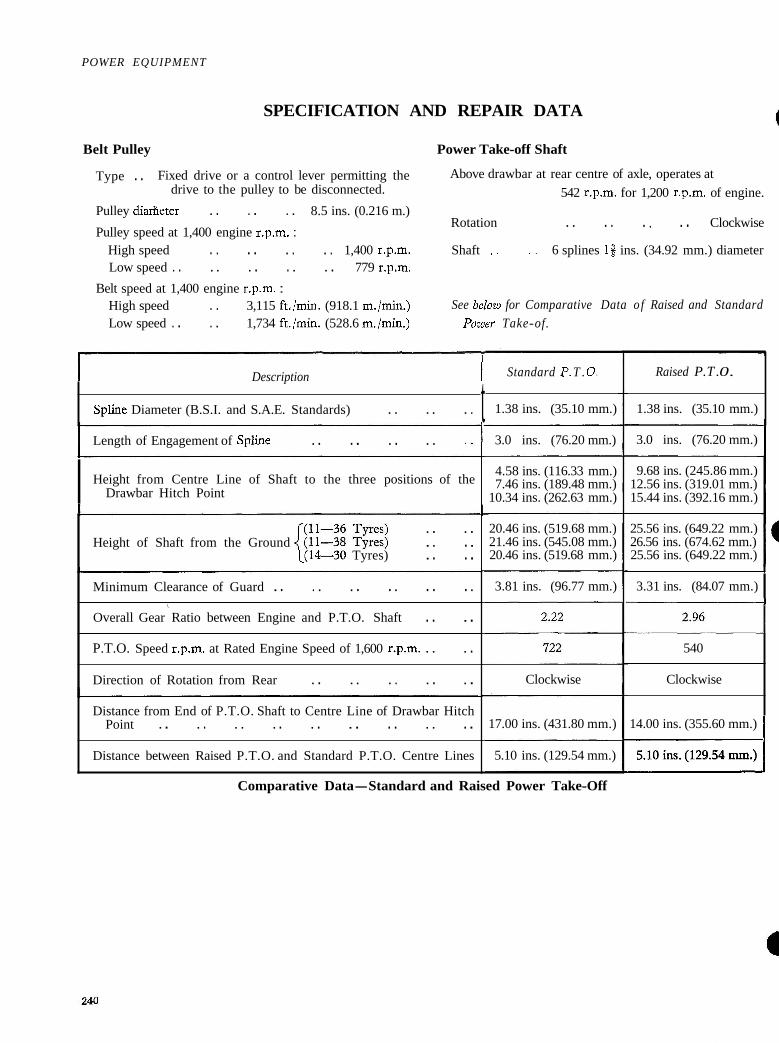
Belt Pulley Power Take-off Shaft
Type . . Fixed drive or a control lever permitting the Above drawbar at rear centre of axle, operates at drive to the pulley to be disconnected. 542 r.p.m. for 1,200 r.p.m. of engine.
Pulley diarheter . . . . . . 8.5 ins. (0.216 m.) Rotation . . . . . , . . Clockwise
Pulley speed at 1,400 engine r.p.m. : High speed . . . . . . . . 1,400 r.p.m. Shaft . . . . 6 splines 18 ins. (34.92 mm.) diameter Low speed . . . . . . . . . . 779 r.p.m.
Belt speed at 1,400 engine r.p.m. : High speed . . 3,115 ft./min. (918.1 m./min.) See below for Comparative Data o f Raised and Standard Low speed . . . . 1,734 ft./min. (528.6 m./min.) Power Take-of.
I Description I Spline Diameter (B.S.I. and S.A.E. Standards) . . . . . . t
Standard P. T . 0.
1.38 ins. (35.10 mm.)
I Length of Engagement of SpIine . . . . . . . . 3.0 ins. (76.20 mm.)
I Height from Centre Line of Shaft to the three positions of the Drawbar Hitch Point
4.58 ins. (116.33 mm.) 7.46 ins. (189.48 mm.)
10.34 ins. (262.63 mm.)
. . . . Height of Shaft from the Ground . . . .
l(l4-30 Tyres) . . . . 20.46 ins. (519.68 mm.) 21.46 ins. (545.08 mm.) 20.46 ins. (519.68 mm.)
Minimum Clearance of Guard . . . . . . . . . . . . \
Overall Gear Ratio between Engine and P.T.O. Shaft . . . .
P.T.O. Speed r.p.m. at Rated Engine Speed of 1,600 r.p.m. . . . .
Direction of Rotation from Rear . . . . . . . . . .
Distance from End of P.T.O. Shaft to Centre Line of Drawbar Hitch Point . . . . . . . . . . . . . . . . . .
Distance between Raised P.T.O. and Standard P.T.O. Centre Lines
3.81 ins. (96.77 mm.)
Clockwise
17.00 ins. (431.80 mm.)
5.10 ins. (129.54 mm.)
Raised P. T . 0.
1.38 ins. (35.10 mm.)
3.0 ins. (76.20 mm.) l 9.68 ins. (245.86 mm.)
12.56 ins. (319.01 mm.) 15.44 ins. (392.16 mm.)
25.56 ins. (649.22 mm.) 26.56 ins. (674.62 mm.) 25.56 ins. (649.22 mm.)
3.31 ins. (84.07 mm.) I
540
Clockwise
14.00 ins. (355.60 mm.) I 5.10 ins. (129.54 mm.) I
Comparative Data-Standard and Raised Power Take-Off
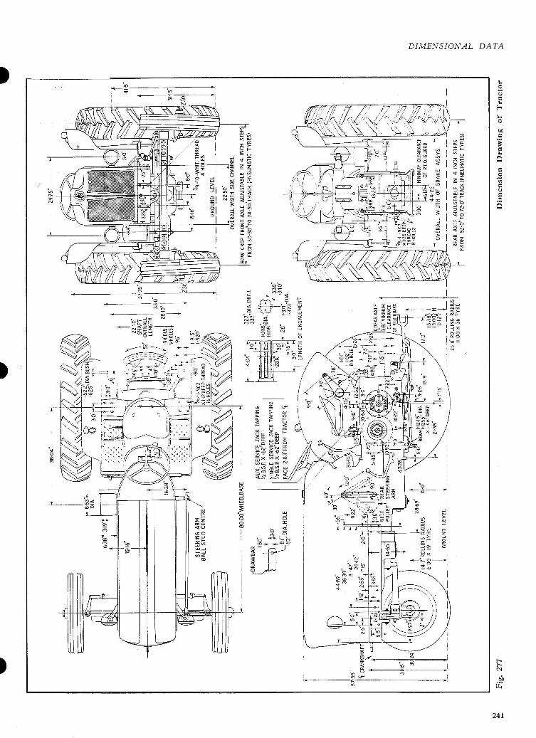
DI"IIEXSI0A'AL DATA
INDEX D=Diesel Engine. P.- V.O.=Petrol--Vaporising Oil Engines. Unless otherwise stated the items refer to all models.
Page Braking System
Adjustments for Normal Lining Wear Brake Cables . . . . . . . . Brake Pedal Cross-shaft . . . . Brake Plate . . . . . . . . Centralising Brake Shoes . . . . Industrial Tractor Brakes . . . . Foot Pedal Linkage . . . . . . Hand Brakes . . . . . . . . Parking Brake . . . . . . . . Steady Post . . . . . . . . Specification and Repair Data . .
Distributor Weight Springs . . . . Generator . . . . . . . . Generator Brushes . . . . . . Generator Commutator . . . . Generator Commutator End Bra~ket . . Generator Drive End Bracket . . Generator Field Coils . . . . . . Headlamps . . . . . . . . Headlamp Bulb . . . . . . Headlamp Glass . . . . . . Horn . . . . . . . . . . Ignition and Light switch . . . . Ignition Coil . . . . . . . . Ignition Timing . . . . . . Lighting System . . . . . . Magneto Ignition . . . . . .
. . . . Magneto Specification . . Side Lamps . . . . . . . . Side Lamp Bulb . . . . . . Side Lamp Glass . . . . . . Spark Plugs . . . . . . . . Specification and Repair Data . . Starter Motor-Diesel . . . . . . Starter Motor-Petrol/Vap. Oil . . Starter Motor Armature (all models) Starter Motor Brushes (all models) . . Starter Motor Commutator (all models) Starter Motor Field Coils (all models) Tail Lamp . . . . . . . . Wiring Diagrams . . . . . .
Clutch Adjustment of Clutch . . . . . . . . . . Adjusting Hydraulic Automatic Clutch Release . . Adjusting Hydraulic Clutch Release Relief Valve . . Clutch Pilot Bearing . . . . . . . . . . Heavy Duty Clutch . . . . . . . . . . Hydraulic Automatic Clutch Release . . . . . . Installation of Hydraulic Automatic Clutch Release . . Maintenance-Clutch Release . . . . . . Overhauling the Clutch . . . . . . . . Specification and Repair Data. . . . . . . . Upper Link-Hydraulic Clutch Release . . . .
Cooling System Draining the System . . . . . . Fan . . . . . . . . . . Fan Belt . . . . . . . . Filling the System . . . . . . Flushing the System . . . . . . Hoses-Radiator . . . . . . Radiator . . . . . . . . . . Specification and Repair Data . . Temperature Gauge . . . . . . Thermostat . . . . . . . . Water Pump . . . . . . . .
Engine ~ u & l i a r ~ Drive Shaft . . . . . .
Camshaft and Tappets . . . .
Connecting Rods . . . . . .
Connecting Rod Alignment . . . . Dimensional Data
Dimensional Chart of Tractor. . . . Crankshaft . . . . . . . .
Electrical System Cylinder Head and Gasket . . . . . . D. Ammeter . . . . . . . . . . . . 221 P.-V.O.
Battery . . . . 191 Cylinder Liners . . . . . . . . . . . . . . . . . . D. P.-V.O.
Controls . . . . . . . . . . . . . . 218 Decarbonising . . . . . . . . . . D. Distributor-Condenser . . . . . . . . 205 P.-V.O. Distributor-Contact Breaker Points . .
:: (I . . 204 Engine Oil Indicator . . . . . . . . . . 62
Distributor . . . . . . . . . . . . 204 D. 16 Distributor Overhaul . . . . . . . . . . 206 P.-V 0 . 42
INDEX
Filter-Engine Oil . . . . . . Flywheel and Ring Gear . . . .
Front Mounting Plate . . . . . .
Injector Houshgs and Seals . . . . Inlet and ~xhaus t Manifold . . . .
Lubrication System . . . . . . Main Bearing Bolts . . . . . .
Main Bearing Caps . . . . . .
Main Bearing Liners . . . . . .
Major Repair Operations . . . .
Manifold-Inlet and Exhaust . . . .
Page 61 30 54 25 50 15 8
36 59 29 54 29 53 28 52 31 54 8
36 Oil Indicator . . . . . . . .
Valve Seats . . . . . . . .
Valve Seat Inserts . . . . . .
Valve Springs . . . . . . . .
Front Axle
Axle Beam . . . . . . . . Drag Link . . . . . . . . Front Axle . . . . . . . . Radius Rod . . . . . . . . Spindle Arm . . . . . . . . Specification and Repair Data . . Spindle Bushes . . . . . . . . Trunnion Pin . . . . . . . . . Wheel Bearings . . . . . .
Front Transmission-Gearbox
Page 13 40 12 39 14 40
170 168 171 170 170 172 171 168 167
Oil Filter . . . . . . . . . . . . 61 Adjustments . . . . . . . . . . . . 131 Oil Pressure Gauge . . . . . . . . . . 62 Gearbox Data . . . . . . . . . . . . 130 Oil Pump . . . . . . . . . . . . 59 Main Gearbox . . . . . . . . . . . . . . 132
D 17 Main Gear Lever . . . . . . . . . . 132 P.-V.o. 42 Primary Gear Lever . . . . . . . . . . 131
Oil Pump Test . . . . . . . . . . . . 61 Primary Gearbox . . . . . . . . . . 132 Pistons . . . . . . . . . .
' ' D l9 Selector Housing and Clutch Balance Lever . . . . 132
Pistons and Connectine: Rods . . -V'o' 45 Specification and Repair Data . . . . . . . . D . 17 . . 136
Piston Pins . . . . . . . . Fuel System
Piston Rings . . . . . . . . . . D . 19 Diesel Fuel System P.-V.O. 44
Pressure Gauge-Oil . . 62 Bleeding the System . . . . . . . . . . . . . . . . . . 9 4
Push Rods and Tappets . . 14 Calibrating the Pump . . . . . . . . D . . . . . 81 & 89 P.-v.o. 40 Camshaft Modified . . . . . . . . . . S 3
Relief Valve-Oil . . . . . . Ring Gear . . . . . . . .
Rocker Shaft . . . . . . . .
Rotator-Type Exhaust Valves . . Specification and Repair Data . . Sump and Gaskets . . . . . .
Timing Cover and Oil Seal . . . .
Timing Gears . . . . . . . .
Valve Grinding . . . . . . . . Valve Guides and Springs . . . . Valve Guides . . . . . . . .
Delivery Valve . . . . . . . . . . 77 & 80 Engine Idling . . . . . . . . . . . . g 1 Excess Fuel and Stop Device . . . . . . . . 7 8 Fault Diagnosis . . . . . . . . . . g 5 Fitting the Pump . . . . . . . . . . g 0 Filter-Fuel Oil . . . . . . . . . . g 4 Injectors . . . . . . . . . . . . g 1 Injectors-Testing . . . . . . . . . . g 2 Injectors-Cleaning . . . . . . . . . . g 2 Injector Pipcs . . . . . . . . . . . . g 5 Lubrication . . . . . . . . . . . . 7 8 Maximum No Load Governed Speed . . . . g 1 Phasing the Pump . . . . . . . . 81 & 86 Pneumatic Governor ... . . . . . . 77 & 80 Pumping Element . . . . . . . . . . 7 6 Pump Storage . . . . . . . . . . . . 8 9 Spill Cut-off Setting . . . . . . . . . . 8 6 Timing the Pump . . . . . . . . . . g 0

INDEX
Fuel Tanks and Fuel Supply Taps
Fuel Lift Pump . . . . Tanks-Fuel . . . . . . Tank Caps . . . . . . Taps . . . . . . . .
7
Vaporiser and Carburettor
Adjustable MeteringIMain Jet Air Cleaner . . . . . . Carburettor . . . . . . IdlingAdjustment . . . . Mechanical Governor . . . . Specification and Repair Data Petrol Starting Carburettor . . Vaporiser . . . . . .
Hydraulic System
Adjusting Rate of Fall . . . . . . . . . . 153 Adjusting Valve Control Unit . . . . .. 152 Control Lever . . . . . . . . . . . . 155 Cross-shaft . . . . . . . . . . . . 158 Diagrammatic Rdpresentation of Hydraulic System . . 150 Fault Diagnosis . . . . . . . . . . .. 165 Hydraulic Pump . . . . . . . . 1478~162 Hydraulic Pump Test . . . . . . . . . . 161 Lift Arms . . . . . . . . . . . . 157 Lowering Position . . . . . . . . . . 152 Magnetic Filters . . . . . . . . . . . . . . 147 Neutral Position . . . . . . . . . . 152 Non-Return Valve Seat . . . . . . . . 154 Non-Return Valve Test . . . . . . . . 153 Piston Valve . . . . . . S . . . . . . 155 Pump Pedestal . . . . . . . . . . . . 164 Pump Pedestal Ball Valves . . . . . . . . 147
. . . . Raised Position . . . . . . . . 152 Raising Position . . . . . . . . . . . . 152 Ram Cylinder . . . . . . . . . . . . 157 Ram Cylinder Piston . . . . . . . . . . 158 Rate of Fall Adjustment . . . . . . . . 153 Specification and Repair Data . . . . . . 166 Unloading Valve Test . . . . . . . . . . 152 Valve Control Unit . . . . . . 148, 153 & 155 Wire Mesh Filter Screen . . . . . . 147&164
Power Equipment
Belt Pulley . . . . . . . . . . . . 235 Check Chains . . . . . . . . . . . . 238 Lift Arms . . . . . . . . . . . . 238 Lift Link . . . . . . . . . . . . 237 Lift Rods . . . . . . . . . . . . 238
244
Lower Links . . . . . . . . Power Take.Off . . . . . . . . Power Take-Off Extension Shaft . . Power Take-Off Selector . . . . Raised Power Take-Off . . . . Raised Power Take-Off Extension Shaft Raised Power Take-Off Installation . . Safety Chains . . ' . . . . . . Specification and Repair Data . .
Rear Transmission-Rear Axle
Axle Shaft . . . . . . Axle Shaft Bearings and Cups Axle Shaft Oil Seal . . . . Axle Shaft Outer Bearings . . Brake Extension Houshgs . . Bull Pinion Bearings . . . . Bull Pinion Housing Bearing Cups Bull Pinion Shaft . . . . Crown Wheel and Differential Drawbar . . . . . . Driving Pinion . . . . . . Rear Transmission . . . . Rear Wheels . . . . . . Rear Wheel Width Adjustment Specification and Repair Data
Separating the Tractor
Dismantling Front Transmission after Engine and Front Axle Separated . . . . . . . . 117
Engine and Front Axle from Front Transmission . . 115 Gearbox and Engine to Rear Transmission . . . . 118 Rear Transmission from Front Transmission and
Engine . . . . .. . . . . . . 118
Steering Gear
Adjustments . . . . . . . . . . . . 174 Lubrication . . . . . . . . . . . . 173 Rocker Shaft . . . . . . . . . . . . 174 Specification and Repair Data . . . . . . 178 Steering Column . . . . . . . . . . 175 Steering Gear . . . . . . . . . . . . 175 Steering Shaft . . . . . . . . . . . . 174
Wheels and Tyres
Dual Rear Wheels . . . . . . . . . . 189 Liquid Ballast . . . . . . . . . . Specification and Repair Data . . . . . . 190 Tyres . . . . . . . . . . . . . . . 189 Wheel Weights . . . . . . . . . . . . 187
SUPPLEMENT
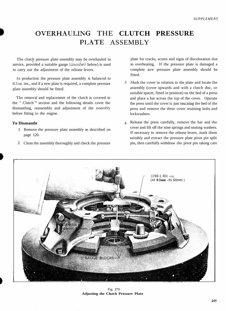
OVERHAULING THE CLUTCH PRESSURE PLATE ASSEMBLY
The clutch pressure plate assembly may be overhauled in I
service, provided a suitable gauge (dcscr~bed below) is used to carry out the adjustment of the release levers.
In production the pressure plate assembly is balanced to 0.5 oz. ins., and if a new plate is required, a complete pressure 3
plate assembly should be fitted.
The removal and replacement of the clutch is covered in the " Clutch " section and the following details cover the dismantling, reassembly and adjustment of the assembly before fitting to the engine.
To Dismantle 4
1 Remove the pressure plate assembly as described on page 120.
2 Clean the assembly thoroughly and check the pressure
plate for cracks, scores and signs of discoloration due to overheating. If the pressure plate is damaged a complete new pressure plate assembly should be fitted.
h4ark the cover in relation to the plate and locate the assembly (cover upwards and with a clutch disc, or suitable spacer, fitted in position) on the bed of a press and place a bar across the top of the cover. Operate the press until the cover is just toucning the bed of the press and remove the three cover retaining bolts and lockwashers.
Release the press carefully, remove the bar and the cover and lift off the nine springs and seating washers. If necessary to remove the release levers, mark them suitably and extract the pressure plate pivot pin split pin, then carefully withdraw the pivot pin taking care
1769-1 831 Ins (44 93mm -46 50mm 1
Fig. 278 Adjusting the Clutch Pressure Plate
SUPPLEMENT-CLUTCH
not to lose the nineteen needle rollers. To dismantle the lever remove the split pin retaining the yoke pin, withdraw the yoke pin and small roller.
To Reassemble and Adjust
Note - To carry gut the adjustment of the release levers it will be necessary to obtain three gauge blocks which can be made from metal strips 5 ins. (127 mm.) long, 0.356 in.-0.366 in. (9.04-9.29 mm.) thick and 1.0 in. (25.4 mm.) wide. (See Fig. 278.) These are placed between the pressure plate and the flywheel to represent the clutch disc for the purpose of this adjustment.
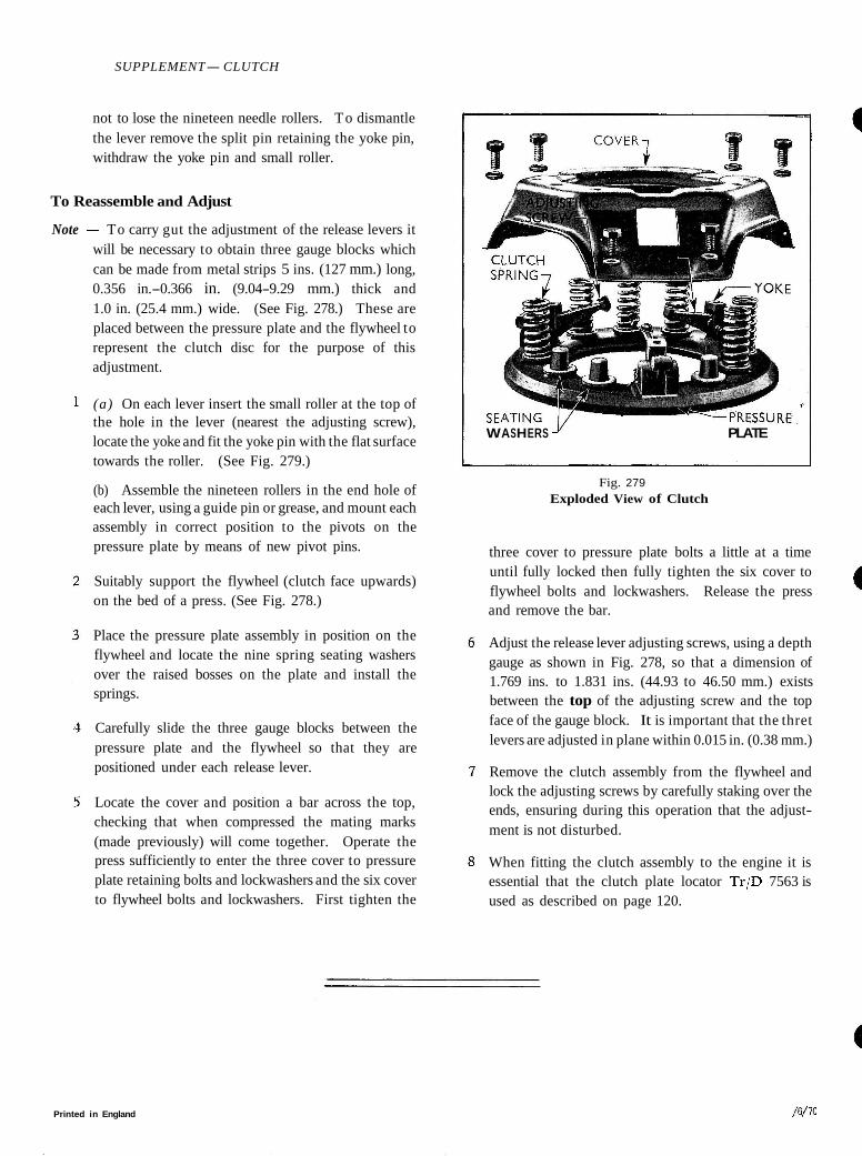
(a) On each lever insert the small roller at the top of the hole in the lever (nearest the adjusting screw), locate the yoke and fit the yoke pin with the flat surface towards the roller. (See Fig. 279.)
(b) Assemble the nineteen rollers in the end hole of each lever, using a guide pin or grease, and mount each assembly in correct position to the pivots on the pressure plate by means of new pivot pins.
Suitably support the flywheel (clutch face upwards) on the bed of a press. (See Fig. 278.)
Place the pressure plate assembly in position on the flywheel and locate the nine spring seating washers over the raised bosses on the plate and install the springs.
Carefully slide the three gauge blocks between the pressure plate and the flywheel so that they are positioned under each release lever.
Locate the cover and position a bar across the top, checking that when compressed the mating marks (made previously) will come together. Operate the press sufficiently to enter the three cover to pressure plate retaining bolts and lockwashers and the six cover to flywheel bolts and lockwashers. First tighten the
WASHERS J' PLATE
Fig. 279 Exploded View of Clutch
three cover to pressure plate bolts a little at a time until fully locked then fully tighten the six cover to flywheel bolts and lockwashers. Release the press and remove the bar.
a Adjust the release lever adjusting screws, using a depth gauge as shown in Fig. 278, so that a dimension of 1.769 ins. to 1.831 ins. (44.93 to 46.50 mm.) exists between the top of the adjusting screw and the top face of the gauge block. It is important that the thret levers are adjusted in plane within 0.015 in. (0.38 mm.)
Remove the clutch assembly from the flywheel and lock the adjusting screws by carefully staking over the ends, ensuring during this operation that the adjust- ment is not disturbed.
When fitting the clutch assembly to the engine it is essential that the clutch plate locator T r / D 7563 is used as described on page 120.
Printed in England / W 7 0