Embed Size (px)
Citation preview
International Journal of Scientific & Engineering Research, Volume 7, Issue 12, December-2016 ISSN 2229-5518
IJSER © 2016
http://www.ijser.org
Magneto Hydro Dynamic Generation Muhammad Muneeb Khan, Muhammad Aamir Shafi, Zahid Riaz
Abstract— Magneto hydrodynamics (MHD) Generator’s working principle based on Faraday law of induction. In MHD generator, salt water
is passed through duct under the presence of strong magnetic field .As a result, voltage is induced and output can be extracted by placing
the electrodes in suitable positions. The mathematical modeling of MHD processes has been done then experimental results obtained
through prototype model verified with simulated results using MATLAB. The MHD generator prototype that is developed and discussed in
this research paper is closed cycle. MHD close cycle has been used for less consumption of electrolyte and due to cost effectiveness. The
voltage induce in this prototype is 2~3v that can be improved by scaling some parameters (magnetic field effect, velocity of fluid, selection
of materials and solution) carefully.
Index Terms— Renewable energy sources, Sustainable energy, Magneto hydrodynamics generator, Electrolytes, Navier stroke
equations, Simulation modeling, Magneto hydrodynamics in Sea water, Prototype model using salt water in MHD
—————————— ——————————
1 INTRODUCTION
he interaction of moving conducting fluids with electric and magnetic fields provides for a rich variety of phe-nomena associated with electro-fluid-mechanical energy
conversion. Effects from such interactions can be observed in liquids, gas-es, two-phase mixtures, or plasmas. Numerous scientific and technical applications exist, such as heating and flow control in metals processing, power generation from two-phase mix-tures or seeded high temperature gases, magnetic confinement of high-temperature plasmas — even dynamos that create magnetic fields in planetary bodies. Several terms have been applied to the broad field of electromagnetic effects in con-ducting fluids, such as magneto-fluid mechanics magneto-gas-dynamics, and the more common one used here — magneto-hydrodynamics, or “MHD”. More recently, MHD devices have been used for stirring, levitating, and otherwise control-ling flows of liquid metals for metallurgical processing and other applications Gas-phase MHD is probably best known in MHD power generation. Major efforts have been carried out around the world to develop this technology in order to im-prove electric conversion efficiency, increase reliability by eliminating moving parts, and reduce emissions from coal and gas plants. Closed-cycle liquid metal MHD systems using both single phase and two-phase flows also have been explored. Still more novel applications are in development or on the horizon. For example, recent research has shown the possibil-ity of seawater propulsion using MHD and control of turbu-lent boundary layers to reduce drag .Extensive worldwide research on magnetic confinement of plasmas has led to at-tainment of conditions approaching those needed to sustain fusion reactions. In the following sections, we review the basic equations describing coupled MHD behavior as well as some basic MHD phenomena in liquids, gases and two-phase mix-
tures. Much of the underlying physics described is common to many of the applications cited above. Also included are dis-cussions of several of the most important applications, togeth-er with their special analysis techniques and examples of equipment involved. One of the current problems in submarine and antisubmarine warfare vessels is the minimization of radiated noise. On nu-clear- powered ships a large fraction of this noise is generated by the steam turbines used to provide the ship's propulsive power and the ship's "hotel" power (i.e. electrical power for lights, radar, sonar, etc.). If electric motors, rather than tur-bines, could be used for these purposes, much of this radiated noise would be eliminated. Furthermore, since for all practical purposes, effective future development of the steam cycle is rapidly nearing an end (in terms of improved efficiency), it seems reasonable to investigate other means of converting nuclear energy to electrical energy that would meet the need for quieter operation at little, or no, loss in efficiency. One possible method of accomplishing this conversion is to couple a magneto-hydro-dynamic generator to a nuclear reac-tor utilizing either a Brayton or a Rankine thermodynamic cycle. Magneto-hydro dynamics, or MHD, uses a magnetic field to convert energy between hydrodynamic and electrical forms. Conductor moving in a magnetic field could be made to generate an electric current, which is the principle that has traditionally been applied to electric motors and generators. the interaction of a current and a magnetic field in a liquid conductor and found that the passage of a current through mercury in an open tray caused a V-shaped depression to form in the center. He suggested this phenomenon ("pinching effect") as the basis for achieving motion without the use of brushes or slip rings. The basic idea of an MHD device is to create a net force, movement, on a charge by producing an electric current per-pendicular to a magnetic field. By using an ionic solution, we are able to produce a net flow of liquid through our MHD without moving parts. Our goal was to design/develop a more efficient pump using MHD theory. The rapid increase in the combustion of power energy created problems that how to enhance generation of power to fulfill
T
————————————————
Muhammad Muneeb Khan, Electrical Engineering, COMSATS Institute of Information Technology, Islamabad, Pakistan, +923047233341, ([email protected]).
Muhammad Aamir Shafi, Electrical Engineering, COMSATS Institute of Information Technology, Islamabad, Pakistan, +923006951920, ([email protected]).
Zahid Riaz, Electrical Engineering, University of Engineering and Tech-nology, Centre of Energy Research & Development, Lahore, Pakistan, +92346-7132337, ([email protected]).
281
IJSER
International Journal of Scientific & Engineering Research Volume 7, Issue 6, June-2016 ISSN 2229-5518
IJSER © 2016
http://www.ijser.org
the needs. All most all the plant converted mechanical energy, into electrical energy .But in MHD (magneto-hydrodynamic) generator the energy of conducting fluids can be directly con-verted into electrical energy. In MHD generator, no mechani-cal parts exist that eliminates frictional losses and reduced the maintenance cost. MHD generator is low cost generator which is beneficial for under developed countries. Plasma based MHD generator also working in developed countries, retro fitting of MHD generator also under process in INDIA [17]. MHD can be classified according to the electrolyte, such as used different gases, salt water, plasma and liquid metals but due to rich sources of salt in Pakistan like salt mines resources that’s why salt water as an electrolyte used in research to pro-duce electricity through MHD generator. Also due to less loss-es because of less friction between different parts [6].MHD Generator process either open cycle or closed cycle. Through MATLAB calculation has made to measure the strength of electric, magnetic field, Lorentz force and velocity of electro-lyte that is moving under the strong magnetic field.
2 DEVELOPMENT OF MHD IN SEA WATER
2.1 Development of MHD in Sea Water
MHD generation only requires the motion of a conducting fluid such as sea water. Thus the presence of the Atlantic in Nigeria makes it a viable method of power generation in the country, in as much as the necessary physical conditions of high conductivity and flow speed can be met.But while the latter can be solved by a suitable engineering design, we must be a bit conservative about the former. The reasons for this conservatism may be apparent from a few observations. First, initial estimates may suggest the practicali-ty of the method, yet it must be noted that only the simplistic Lorentz force law coupled with the definition of work, which leads to an estimate of motional EMF in a medium such as flowing salt water, which contains charged ions, has been used in obtaining this estimate. In-depth analysis requires a consideration of both the Navier-Stokes equation and the Maxwell’s law of electromagnetism in addition to the Lorentz force law. Second, research in other places on sea water has shown that MHD has exclusively been in respect of developing high speed boats that exploit the Lorentz force law by sending in-tense electric currents into the surrounding sea water, while MHD electric power generation has been exclusively restricted to the use of plasma. So if it turns out that the reason for this is that sea water just isn’t conducting enough on the basis of oth-er considerations that go deeper than the Lorentz force Law, we cannot do much, since any attempt to adjust the conductiv-ity of the sea water would alter its salinity, which is not advis-able for the reasons of conservation of the natural habitat. Put-ting all this into perspective, therefore, it should be said that more research is needed to decide on the feasibility of the method, which we shall undertake in the sequel to the present paper. However, encouraging in this regard is that U tube demonstrations have shown small scale successes in France and England using the method, although demonstrations are in controlled environments and the voltages shown in the
demonstrations are terribly fluctuating.
2.2 General Design of MHD:
MHD is a design that consisted of two strong magnets and
two electrodes, assembled within a custom acrylic housing. With this design, we hoped to propel a highly saturated liquid through an acrylic box by creating very strong perpendicular electric and magnetic fields.
A magneto hydrodynamics drive (MHD) deals with con-cepts from the combined fields of physics, chemistry, electrical engineering, and mechanical engineering. The basic idea of an MHD device is to create a net force, movement, on a charge by producing an electric current perpendicular to a magnetic field. By using an ionic solution, we are able to produce a net flow of liquid through our MHD without moving parts.
2.3 Prototype Model
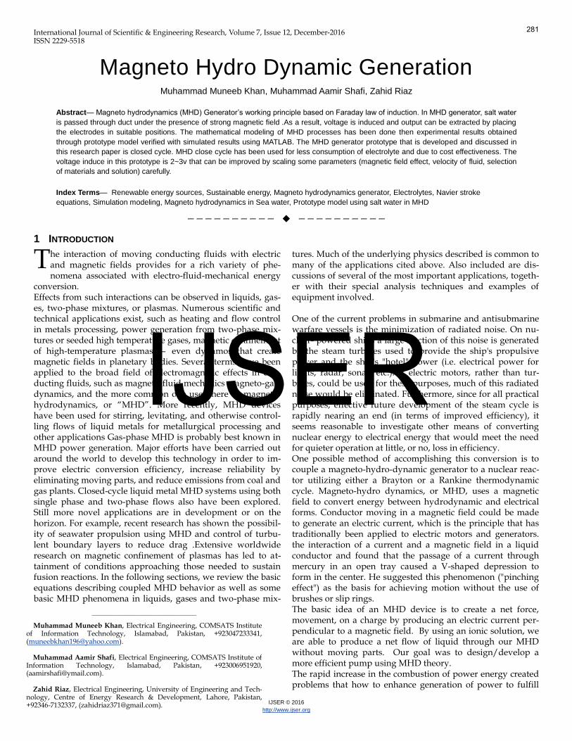
Fig.1 Schematic Model of MHD
2.4 MHD Prototype Model
The basic principal for MHD generator is based on Fara-day’s law of induction. Firstly work done on theory, feasibility and previously developed models, that provided different ideas to built efficient MHD generator. In the initial stage of prototype model preparation, a rectangle type duct for the flow of salt water built, that duct is made up of transparent material. Different electrodes configuration has been em-ployed for the accumulation of charges and creation of electric field perpendicular to the magnetic field in experiments. In initial stage both electrodes of zinc for collection of different polarities charges (+ve and -ve), due to high electro-negativity (ability to attract electrons) it act as positive electrode and able to accumulate more negative charges. Next both electrodes of copper have been used and it proves more efficient for posi-tive charges due to less electro-negativity. One behave as more electropositive and other as more electronegative, due to this reason use of one copper electrode and other one zinc elec-trode has been made and accurate results up-to some instant obtained. The properties of copper and zinc that , both were employed for charge accumulation due to their conductivity which depends upon the size of electrodes as well as magnetic properties of material. These electrodes act as anode and cath-ode for accumulation of charges. Electrodes used in this model should have more conductivity as values given in (table 2). Its working principal is similar to mechanical dynamo in which a conductor moves and cut the magnetic field lines as a result
282
IJSER
International Journal of Scientific & Engineering Research Volume 7, Issue 6, June-2016 ISSN 2229-5518
IJSER © 2016
http://www.ijser.org
induce voltage. But in MHD generator, salt water fluid used instead of conductor which provides best efficiency due to absence of mechanical part. Moving fluid that contain 75% of water and 25% of salt (Nacl), for the best result or more charg-es their concentration must be same [5]. To produce magnetic field permanent magnets used, for better results neo-magnets may be employed due to high magnetic field effect. The fluid recycled to make the circuit as close loop, due to this salted water can be used again and again for more generation. With these parameters and evolutions of different new ideas, devel-opment of different models has been made. It enables us to built final MHD prototype that is shown in figures. For more accurate results from MHD prototype, we need better instru-ments .The process to develop is same as describe above and working on same principal. Schematic diagram of MHD sys-tem is shown in fig 5 and prototype model is shown in fig 6(I,II).
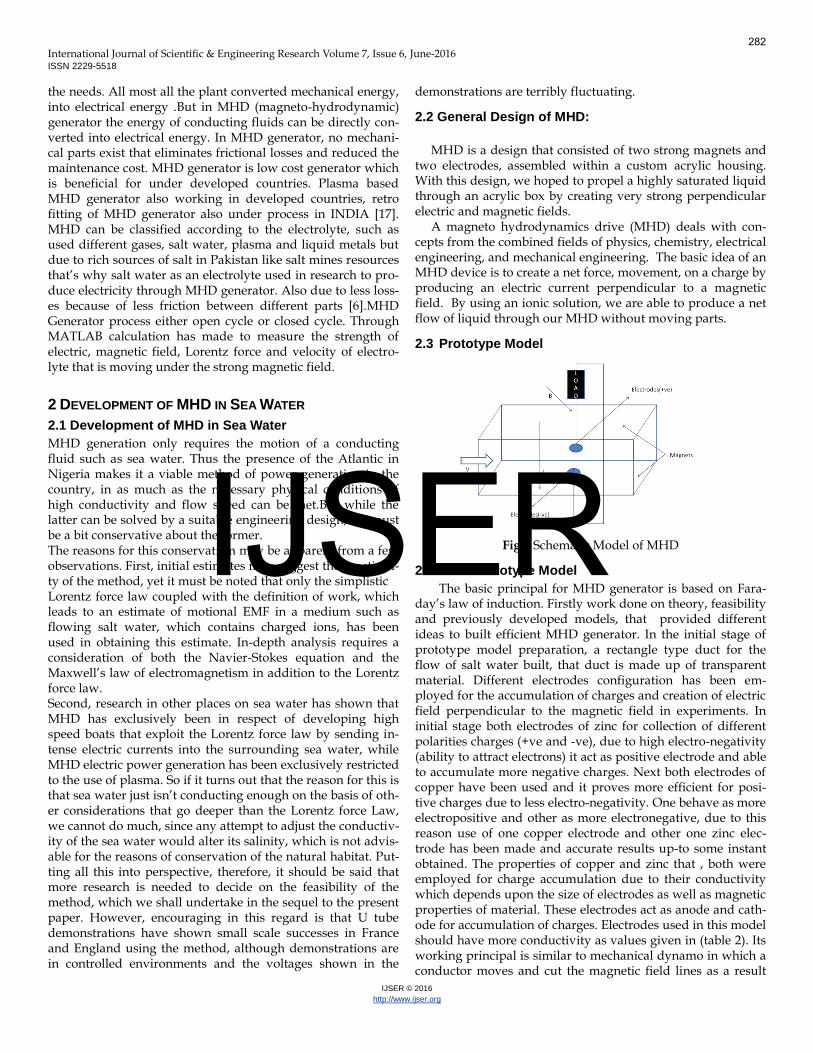
Fig.2 Prototype Model of MHD Selection of electrodes: Depends on conductivity Depends on cost and availability Ionization is directly proportional to the conductivity[18].
Table.1 Conductivity of different materials
Material of Electrode Conductivity(% IACS)
Lead 8.4
Copper 100
Zinc(Commercial rolled) 28
Platinum 16.28
Gold 73.4
Silver 105
3 WORKING PRINCIPAL
3.1 Protoype using Salt Water as An Electrolyte
With the knowledge on few basic ideas of MHD generator, first phase of work was basic research on the paper developed. The basic principal for MHD generator is based on Faraday’s law of induction. Firstly work done on theory, feasibility and previously developed models, which provided different ideas to built efficient MHD generator. In the initial stage of proto-type model preparation, a rectangle type duct for the flow of salt water built, that duct is made up of transparent material. Different electrodes configuration has been employed for the accumulation of charges and creation of electric field perpen-dicular to the magnetic field in experiments. In initial stage both electrodes of zinc for collection of different polarities
charges (+ve and -ve), due to high electro-negativity (ability to attract electrons) it act as positive electrode and able to accu-mulate more negative charges. Next both electrodes of copper have been used and it proves more efficient for positive charg-es due to less electro-negativity. One behave as more electro-positive and other as more electronegative, due to this reason use of one copper electrode and other one zinc electrode has been made and accurate results up-to some instant obtained. One advantage of these electrodes is that they prevent from corrosion. Due to properties of copper and zinc, both were employed for charge accumulation due to their conductivity which depends upon the size of electrodes as well as magnetic properties of material. These electrodes act as anode and cath-ode for accumulation of charges. Electrodes used in this model should have more conductivity as values given in table 1. Its working principal is similar to mechanical dynamo in which a conductor moves and cut the magnetic field lines as a result induce voltage. But in MHD generator, salt water fluid used instead of conductor which provides best efficiency due to absence of mechanical part. Moving fluid that contain 75% of water and 25% of salt(Nacl), for the best result or more charg-es their concentration must be same. To produce magnetic field permanent magnets used, for better results neo-magnets may be employed due to high magnetic field effect. The fluid recycled to make the circuit as close loop, due to this salted water can be used again and again for more generation. With these parameters and evolutions of different new ideas, devel-opment of different models has been made. It enables us to built final MHD prototype that is shown in figures. For more accurate results from MHD prototype, we need better instru-ments .The process to develop is same as describe above and working on same principal.
3.2 Using different Salt and Solution as An Electrolyte
With the knowledge on few basic ideas of MHD generator, first phase of work was basic research on the paper developed.
Without prior knowledge of the area of MHD, we began our project with basic research into applications, previous de-signs, and theory. This provided us with ideas for the major parts and fundamental ideas required to build a MHD genera-tor. Our main components consisted of two strong neodymi-um magnets connected to two ferromagnetic arches to form a focused magnetic field. We also used two electrodes to create a strong electric field perpendicular to the magnetic field. These were made of copper and aluminum to resist corrosion. In addition, we created a custom housing to contain our test-ing device.With basic research complete and ideas flowing, we produced several alternate designs of the project. First, we found two strong magnets that would be the center of our de-sign. Next, we experimented with ionic solutions to insure a harmful gas would not be produced, we settled on MgSO4 (Epsom Salt). We then tested electrodes for resistance to cor-rosion by inducing an electrolysis reaction between electrodes of varying materials in our ionic solution. In addition to these test results we needed a material for our electrodes that is non-magnetic, so as not to disrupt the magnetic field. With this experiment, we determined that aluminum and copper were most resistive to corrosion and electroplating, furthermore
283
IJSER
International Journal of Scientific & Engineering Research Volume 7, Issue 6, June-2016 ISSN 2229-5518
IJSER © 2016
http://www.ijser.org
they are easily accessible. This knowledge enabled us to start designing the final MHD generator.
MHD design consisted of a basic acrylic box that would house the electrodes and the liquid solution on the inside and the magnets and ferromagnetic arches on the outside; this would be connected to two side tanks connected by an equal-izer tube to maintain a constant water level. We used a laser to cut out the MHD box and cut precisely measured holes needed to fit the MHD box and equalizer tube in both tanks. This enabled us to exactly fit the MHD box and the equalizer tube into the two side tanks and ensure a watertight seal by using 100% silicon rubber sealant. Our final modifications of the design included curved plastic deflectors to smooth out turbulence and a pressure gauge in the equalizer tube to give a rough power estimate of our MHD’s fluid output. Another addition was foam, cut and fit to prevent the electrodes from falling over. With our system constructed, we proceeded with testing of the MHD generator. We experimented with elec-trode material placement, magnetic placement, ferromagnetic material, power intensity, plastic deflector placement, and the velocity of liquid. Most of our research was performed on ma-terials, as the physics behind MHD was already solved for us. We experimented with less corrosive electrolyte solutions, better electrodes, and observed the effects of focusing the magnetic and electrical fields. Our first concern was the dead-ly chlorine gas produced by NaCl during electrolysis. We cir-cumvented this problem by using MgSO4 (Epsom Salt), how-ever this did not solve our corrosion problem. Our search for a less corrosive electrolyte, pointed us away from ionic solu-tions and towards de-ionized water. De-ionized water cut down build-up of material on the electrodes significantly; however, we can obtain de-ionized water in limited quantities only. After discovering a proper electrolyte solution, we fo-cused on finding the optimal material for our electrodes. Through five-minute timed resistance tests and observations, we determined that copper and aluminum would serve us best during an oxidation-reduction reaction. Any build up of chemicals on copper, would only change the resistance slight-ly and could be quickly and easily removed, unfortunately after testing aluminum with more power we noticed a build up of material on the aluminum electrodes that we could not easily take off. With this in mind we decided to use only cop-per.
Table.2 Resistance of different materials
We ran a number of tests involving focused magnetic and
electrical fields. From these tests, we determined that focusing does in fact increase the effectiveness of our MHD device. Velocity inside the MHD channel was so fast that we were unable to take ac-
curate measurements with equipment at hand, however we can estimate the average velocity of the water pumped to be about 0.18 seconds per inch at the outlet.We were largely un-successful finding a less corrosive electrolyte. We eventually realized that our source of water (tap) was most likely the cause of chemical build up on the electrodes. After testing with de-ionized water, we confirmed this hypothesis. Our decision to use copper was surprising to us, however, once one considers that copper is quickly cleaned, and relatively stable in terms of change of resistance, then copper appears to be the choice electrode. When the magnetic and electric fields were unfocused, the velocity of flow would slow down due to opposing forces created when the magnetic field ran in oppo-site directions to the electric current. Without the use of fer-romagnetic material to create a uniform focused field, the MHD channel was less efficient, because of counteracting forces on the charged solution, which in turn propelled less water. To avoid this we connected both magnets with two arches of ferromagnetic material to focus the magnetic field. This proved to be an effective modification to the MHD chnnel as it now propelled the fluid considerably faster than with an unfocused field. By angling the electrode plates, a smaller cross sectional area was formed increasing the velocity of the water based on Bernoulli’s principle, furthermore by angling the plates the electric field and magnetic field would interact to focus the resultant force to a point.The liquid was propelled so quickly that the MHD force on the water created turbulence in the tanks and eddies in the MHD pump. We inserted plas-tic deflectors in both side tanks and fitted foam pieces in the MHD pump. The plastic deflectors corrected the turbulence and the foam stopped the circular eddies around the elec-trodes. 3.3 Principle of Magneto Hydrodynamic Power
Generation
When an electric conductor is moved so as to cut lines of magnetic induction, the charged particles in the conductor experience a force in a direction mutually perpendicular to the B field and to the velocity of the conductor. The negative charges tend to move in one direction and the positive charges in the opposite direction. This induced electric field or mo-tional EMF provides the basis for converting mechanical ener-gy into electrical energy. At present, nearly all electrical power generators utilize solid conductors which are caused to rotate between the poles of a magnet. In the case of hydroelectric generators, the energy required to maintain the rotation is supplied by the gravitational motion of river water. Turbo generators, on the other hand, generally operate using a high-speed flow of steam or other gas. The heat source required to produce the high speed gas flow may be supplied by the com-bustion of a fossil fuel or by a nuclear reactor.
For magneto hydrodynamic power generation, the solid conductor of a conventional generator is replaced by a fluid conductor. The fluid can be a liquid metal or heated and seed-ed noble gas. In an open cycle MHD generator, a fossil fuel, burnt in oxygen or preheated compressed air, is seeded with an element of low ionization (such as potassium or caesium ). This element is thermally ionized at the combus-tion temperature (usually over 2500K) producing sufficient
Material ∆Ω(resistance)
Copper 0.3
Stainless Steel 0.2
Graphite 4.5
Aluminum 0.1
284
IJSER
International Journal of Scientific & Engineering Research Volume 7, Issue 6, June-2016 ISSN 2229-5518
IJSER © 2016
http://www.ijser.org
free electrons eg (K→ K++ e) to produce adequate electrical conductivity. The interaction between the moving conducting fluid and the strong applied magnetic fluid across it generates an E.M.F on the faraday principle. The power output per unit fluid volume (W) is given by
W = Kσν2Β2 Where
σ stands for the conductivity ν stands for its velocity Β stands for the magnetic flux density K is a constant.
The Lorentz force law describes the effects of a charged parti-cle moving in a constant magnetic field. The simplest form of this law is given by the vector equation
F = Q· (v × B) Where
F stands for the force acting on the particle Q stands for the charge on the particle V stands for the velocity B stands for the magnetic field. The vector F is perpendicular to both v and B according to
the right hand rule. In a closed-cycle system of MHD, the fluid is continuously re circulated through a compressor; the fluid consists of a heated and seeded noble gas or liquid metal.
Our proposed MHD generator is one whose fluid conduc-tor is salt water. MHD is suitable to meet high short term de-mands. This of course is a non renewable source and has a major drawback of which air pollution is the lead. Harnessing power by employing an MHD generator with salt water as its fluid conductor is hugely advantageous in that the source is renewable, it requires no external energy input to facilitate its operation, it has no moving parts and as such does not con-tribute to mortality of aquatic organisms and finally, it does not pose problems of pollution.
4 SELECTION OF MATERIALS
4.1 Electrode Selection
Electrodes can be selected depends on their conductance in MHD channel. They maybe some type of metal but with good conductance and less resistance.
Table.3 Resistance of Different Material Less resistance is better
Table.4 Conductivity of Different Materials
Material of Electrode Conductivity(% IACS)
Lead 8.4
Copper 100
Zinc(Commercial rolled) 28
Platinum 16.28
Gold 73.4
Silver 105
Selection of electrodes depends on also:
Conductivity Cost and availability
4.2 Solution Selection
The best solution is that which can produce more ions in solution and different type of solution available for MHD channel like H2SO4, HCL, KCL solution, salt water, NAOH solution, all these solution can be used but depends upon their conductivity and availability and cost. All these factors are important for the selection of solution that used in MHD solu-tion. 4.3 Magnets Selection
Magnets are must be one which create strong magnetic field and that are only neodymium magnets. Other circular or cylindrical magnets are not create strong magnetic field and in this way no magnetic fields effect come in the MHD channel so just for this way there strong magnetic field neodymium magnets are required. Which create strong magnetic field for electrolyte. There can be coils also used but better results only give neodymium magnets are the best for electrolyte solutions.
5 MHD EQUATIONS
5.1 Flow Equations
NAVIER STOKES equation is very important equation in the field of fluid dynamics.
A simplification of the resulting flow equations is obtained when considering an incompressible flow of a Newtonian flu-id. The assumption of incompressibility rules out the possibil-ity of sound orshock wavesto occur; so this simplification is not useful if these phenomena are of interest. The incompress-ible flow assumption typically holds well even when dealing with a "compressible" fluid, such as air at room temperature at low Mach numbers (even when flowing up to about Mach 0.3). Taking the incompressible flow assumption into account and assuming constant viscosity, the Navier–Stokes equations will read, in vector form:
It describe the motion of fluid substances .In this case, flu-id under consideration is incompressible
A continuity equation in physics is an equation that de-
scribes the transport of a conserved quantity. Since mass, energy, momentum, electric chargeand other nat-ural quantities are conserved under their respective appropri-ate conditions, a variety of physical phenomena may be de-scribed using continuity equations.
Continuity equations are a stronger, local form of conservation laws. For example, it is true that "the total en-ergy in the universe is conserved". But this statement does not immediately rule out the possibility that energy could disap-pear from Earth while simultaneously appearing in another galaxy. A stronger statement is that energy is locally conserved: Energy can neither be created nor de-stroyed, nor can it "teleport" from one place to another—it can only move by a continuous flow. A continuity equation is the mathematical way to express this kind of statement.
Continuity equations more generally can include "source"
∆Ω (resistance) Material
0.3 Copper
0.2 Stainless Steel
4.5 Graphite
0.1 Aluminum
285
IJSER
International Journal of Scientific & Engineering Research Volume 7, Issue 6, June-2016 ISSN 2229-5518
IJSER © 2016
http://www.ijser.org
and "sink" terms, which allow them to describe quantities that are often but not always conserved, such as the density of a molecular species which can be created or destroyed by chem-ical reactions. In an everyday example, there is a continuity equation for the number of living humans; it has a "source term" to account for people giving birth, and a "sink term" to account for people dying.
Any continuity equation can be expressed in an "integral form" (in terms of a flux integral), which applies to any finite region, or in a "differential form" (in terms of the divergence operator) which applies at a point.
Continuity equations underlie more specific transport equations such as the convection–diffusion equa-tion, Boltzmann transport equation, and Navier-Stokes equa-tion
Where u velocity field p the dynamic pressure j current density B magnetic field F volumetric force
operator As changing the entering and leaving area of fluid varies
the velocity and pressure of fluid that describe through these equations.
where P pressure A cross sectional area
wall conductance ampere current
charge density
/Area
a inlet area of duct b outlet area of duct v velocity
5.2 Electric Equations
Ohm's Law cited above is a constitutive relationship (for instance, analogous to the Equation of state for gases) and as such has a limited range of applicability. Various forms of Ohm’s Law can be obtained depending upon the approxima-tions made in deriving the current-field relationships from the equations of motion and the interactions of the constituent parts of the fluid.
Where B Magnetic field V velocity E electric field
Distance between electrodes
5.3 Magnetic Induction Equations
Electromagnetic induction was discovered independently by Michael Faraday and Joseph Henry in 1831; however, Far-aday was the first to publish the results of his experiments. In Faraday's first experimental demonstration of electromagnetic induction (August 29, 1831he wrapped two wires around op-posite sides of an iron ring or "torus" (an arrangement similar to a modern toroidal transformer). Based on his assessment of recently discovered properties of electromagnets, he expected that when current started to flow in one wire, a sort of wave would travel through the ring and cause some electrical effect on the opposite side. He plugged one wire into a galvanometer, and watched it as he connected the other wire to a battery. Indeed, he saw a transient current (which he called a "wave of electricity") when he connected the wire to the battery, and another when he disconnected it.This induc-tion was due to the change in magnetic flux that occurred when the battery was connected and disconnected Within two months, Faraday had found several other manifestations of electromagnetic induction. For example, he saw transient cur-rents when he quickly slid a bar magnet in and out of a coil of wires, and he generated a steady (DC) current by rotating a copper disk near the bar magnet with a sliding electrical lead ("Faraday's disk")
Faraday explained electromagnetic induction using a con-
cept he called lines of force. However, scientists at the time widely rejected his theoretical ideas, mainly because they were not formulated mathematically. An exception was Maxwell, who used Faraday's ideas as the basis of his quantitative elec-tromagnetic theory. In Maxwell's papers, the time varying aspect of electromagnetic induction is expressed as a differen-tial equation which Oliver Heaviside referred to as Faraday's law even though it is slightly different in form from the origi-nal version of Faraday's law, and does not describe motional EMF. Heaviside's version (see Maxwell–Faraday equation be-low) is the form recognized today in the group of equations known as Maxwell's equations.
Magnetic induction equation describe that the motion of a
conducting liquid in an applied magnetic field will induced a magnetic field in the medium. The total field is the sum of ap-plied and induced magnetic field.
Magnetic induction is derived by taking the curl of Ohms law. Induction equation links it with magnetic field, velocity field and the diffusion of the magnetic field within the do-main.
=
where E electric field U velocity of liquid
It also depend upon flow continuity, continuity equation
describe that In 1831, Michael Faraday, an English physicist gave one of
most basic law of electromagnetism called Faraday's law of
286
IJSER
International Journal of Scientific & Engineering Research Volume 7, Issue 6, June-2016 ISSN 2229-5518
IJSER © 2016
http://www.ijser.org
electromagnetic induction. This law explains the working principle of most of electrical motors, generators electrical transformers and inductors. This law shows the relationship between electric circuit and magnetic field. Faraday performs an experiment with a magnet and coil. During this experiment he found how EMF is induced in the coil when flux linked with it changes. He has also done experiments in electrochem-istry and electrolysis.
Faraday’s law describe the effect of changing magnetic
field on induce EMF. Any change in the magnetic field produced EMF, no mat-
ter how the change is it will produce voltage.
operator E= Electric field
=change in magnetic field According to Electromagnetic equations, it describe the in-
teraction between electric and magnetic field in a continuous medium
Describe electric charges distributed with in the medium.
Equation(8) shows how the changing of magnetic field pro-duced the electric field. 5.4 Chemical Equations
It's interesting to understand every aspect of this demon-stration, within the capabilities of graduation students. One very interesting aspect, which involves a little chemistry 12, concerns the question: how do the electrons "flow" through the salt water from one electrode to the other?
This might be a natural question since the force which propels the MHD boat comes from the motion of the SODIUM and CHLORINE ions in the magnetic field and NOT from any moving electrons. In fact, the electrons do not directly travel through the water at all.
In explaining this you need to consider the electro-chemical reactions which occur at each electrode. From a re-duction/oxidation table in a standard Chem. 12 text you can come up with the equations for the electrolysis of salt water:
Reduction of water at the negative electrode 2H2O + 2e- → H2(gas) + 2OH-
Oxidation of chlorine ions at the positive electrode 2Cl → Cl2(gas) + 2e-
The 2Na+ ions are attracted to negative electrode and combine with the 2OH- ions to form NaOH.
NaCl(aq) + H2O → H2(g) + Cl2(g) + NaOH(aq) So you can see that electrons are taken up at one electrode
and given up at the other electrode to simulate a current flow. Indeed the properties of this behavior approximate the elec-tron flow through wire and any calculations done can be as if the electrons actually do produce a regular circuit.
6 RESULTS AND DISCUSSIONS
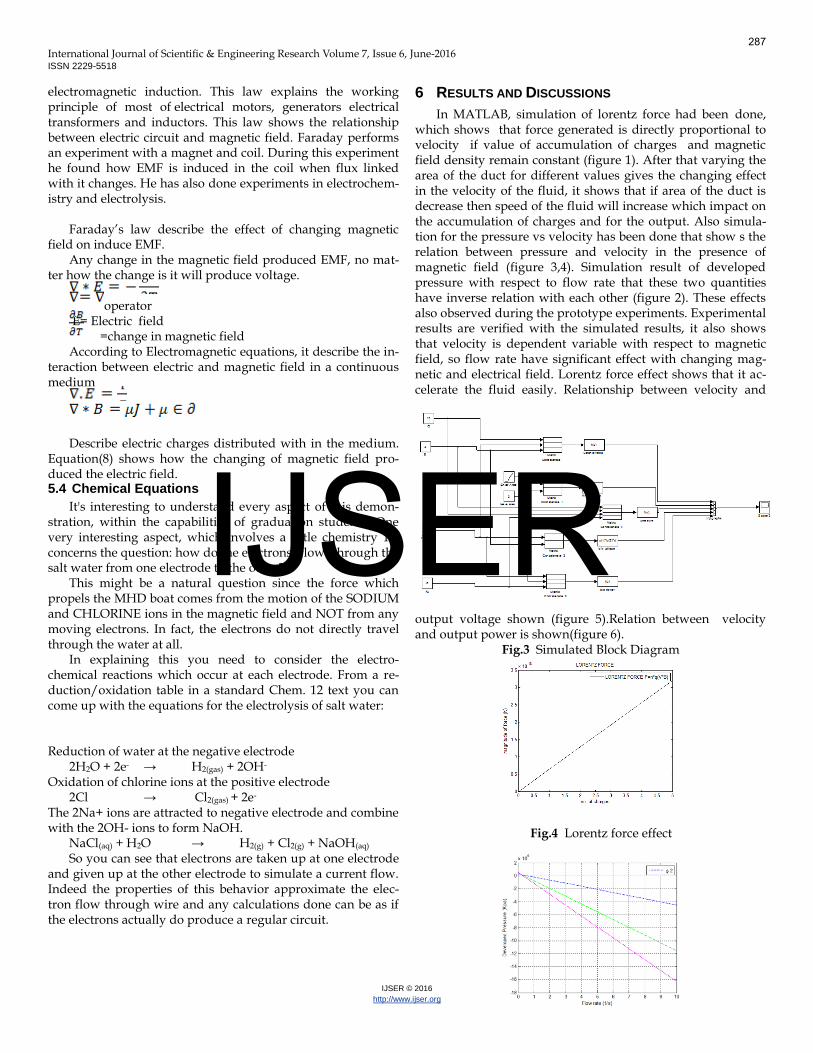
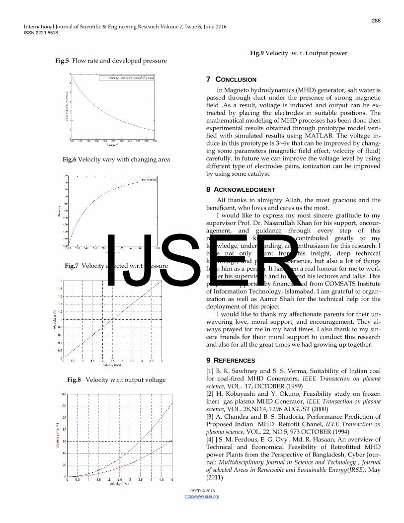
In MATLAB, simulation of lorentz force had been done, which shows that force generated is directly proportional to velocity if value of accumulation of charges and magnetic field density remain constant (figure 1). After that varying the area of the duct for different values gives the changing effect in the velocity of the fluid, it shows that if area of the duct is decrease then speed of the fluid will increase which impact on the accumulation of charges and for the output. Also simula-tion for the pressure vs velocity has been done that show s the relation between pressure and velocity in the presence of magnetic field (figure 3,4). Simulation result of developed pressure with respect to flow rate that these two quantities have inverse relation with each other (figure 2). These effects also observed during the prototype experiments. Experimental results are verified with the simulated results, it also shows that velocity is dependent variable with respect to magnetic field, so flow rate have significant effect with changing mag-netic and electrical field. Lorentz force effect shows that it ac-celerate the fluid easily. Relationship between velocity and
output voltage shown (figure 5).Relation between velocity and output power is shown(figure 6).
Fig.3 Simulated Block Diagram
Fig.4 Lorentz force effect
287
IJSER
International Journal of Scientific & Engineering Research Volume 7, Issue 6, June-2016 ISSN 2229-5518
IJSER © 2016
http://www.ijser.org
Fig.5 Flow rate and developed pressure
Fig.6 Velocity vary with changing area
Fig.7 Velocity affected w.r.t pressure
Fig.8 Velocity w.r.t output voltage
Fig.9 Velocity w. r. t output power
7 CONCLUSION
In Magneto hydrodynamics (MHD) generator, salt water is passed through duct under the presence of strong magnetic field .As a result, voltage is induced and output can be ex-tracted by placing the electrodes in suitable positions. The mathematical modeling of MHD processes has been done then experimental results obtained through prototype model veri-fied with simulated results using MATLAB. The voltage in-duce in this prototype is 3~4v that can be improved by chang-ing some parameters (magnetic field effect, velocity of fluid) carefully. In future we can improve the voltage level by using different type of electrodes pairs, ionization can be improved by using some catalyst.
8 ACKNOWLEDGMENT
All thanks to almighty Allah, the most gracious and the beneficent, who loves and cares us the most.
I would like to express my most sincere gratitude to my supervisor Prof. Dr. Nasarullah Khan for his support, encour-agement, and guidance through every step of this research. His kind efforts contributed greatly to my knowledge, understanding, and enthusiasm for this research. I have not only learnt from his insight, deep technical knowledge, and practical experience, but also a lot of things from him as a person. It has been a real honour for me to work under his supervision and to attend his lectures and talks. This project is supported by financial aid from COMSATS Institute of Information Technology, Islamabad. I am grateful to organ-ization as well as Aamir Shafi for the technical help for the deployment of this project.
I would like to thank my affectionate parents for their un-wavering love, moral support, and encouragement. They al-ways prayed for me in my hard times. I also thank to my sin-cere friends for their moral support to conduct this research and also for all the great times we had growing up together.
9 REFERENCES
[1] B. K. Sawhney and S. S. Verma, Suitability of Indian coal for coal-fired MHD Generators, IEEE Transaction on plasma science, VOL. 17, OCTOBER (1989) [2] H. Kobayashi and Y. Okuno, Feasibility study on frozen inert gas plasma MHD Generator, IEEE Transaction on plasma science, VOL. 28,NO 4, 1296 AUGUST (2000) [3] A. Chandra and B. S. Bhadoria, Performance Prediction of Proposed Indian MHD Retrofit Chanel, IEEE Transaction on plasma science, VOL. 22, NO 5, 973 OCTOBER (1994) [4] ] S. M. Ferdous, E. G. Ovy , Md. R. Hasaan, An overview of Technical and Economical Feasibility of Retrofitted MHD power Plants from the Perspective of Bangladesh, Cyber Jour-nal: Multidisciplinary Journal in Science and Technology , Journal of selected Areas in Renewable and Sustainable Energy(JRSE), May (2011)
288
IJSER
International Journal of Scientific & Engineering Research Volume 7, Issue 6, June-2016 ISSN 2229-5518
IJSER © 2016
http://www.ijser.org
[5] R. Yaduvanshi ,H. Parthasarthy, Exact solution of Magne-to-Hydrodynamic System with non linearity analysis, journal of theoretical applied information technology, APRIL (2011) [6] R. S. Yaduvanshi, H. Parthasarathy, Development and Simulations of MHD Equations with its proto type implemen-tation, (IJACSA) International Journal of Advanced Computer Science and Applications, VOL. 1, NO 4, OCTOBER (2010) [7] E. M. Braun, F. K. Lu, and D. R. Wilson, A Critical Review of Electric and Electromagnetic Flow Control Research Ap-plied to Aerodynamics , MS THESIS University of Texas at Ar-lington ,Arlington, Texas, 76019, USA, (2008) [8] A. Liberati, T. Murakami, Simulation on Performance of MHD Generator in the Closed- loop Experimental Facility, IEEE Transaction on plasma science, VOL.34,NO.6,2669(2006) [9] Takeda, Okuji, Fundamental Studies of Helical-Type Sea-water MHD Generation System, IEEE Transaction on applied superconductivity, APRIL (2005) [10] J. D. Hutchinson, Magneto-hydrodynamic power genera-tion for nuclear-powered sea-going vessel, MS THESIS, MAY (1996) [11] M. Freeman, MHD pulsed for geophysical research, EIR Science and Technology, VOL 22,NO 25, JUNE (1995) [12] V. DOUSSET, Numerical simulations of MHD flows past obstacles in a duct under externally applied magnetic field ,Coventry University, MS THESIS DECEMBER (2009) [13] S. O. Mathew , O, C. Dike, E. U. Akabuogu, Magneto-hydrodynamic power generation using salt water, Asian Jour-nal of Natural and Applied Science, ISSN: 2186-8468, VOL. 1 DECEMBER, ( 2012) [14] A. T. Eswara, Hasan, S. Roy, Madras, and G. Nath , Ban-galore, Unsteady MHD forced flow due to a point sink, Atca Mechanica 145,159-172, (2000) [15] V. Chernyshev, International co-operation in MHD Elec-trical power generation, IAEA BULLETEN, VOL. 20, NO 1, (1966) [16] K. V. S. Sundaram, S. K. Somasundaram, S. Sridharan, MHD Research project ,Bharat Heavy Electricals Limited, Tiruchirapalli,620 014,(1985) [17] V. D. Dhareppagol & A. Saurav , The future power gener-ation with MHD Generators Magneto Hydro Dynamic genera-tion, Bijapur-586103. India, ISSN:2278-8948, Volume-2, (2013)
[18] A. K. R , J. B. S, Magnetohydrodynamic Power Genera-tion,International Journal of scientific and Reaearch Publication, Volume 3, JUNE (2013)
289
IJSER