Embed Size (px)
Citation preview
MM. 22.6.2
P.O. ENGINEERING DEPARTMENT EDUCATIONAL PAMPHLET - DRAFT SERIES TELEPHONES 2/2
MAGNETO AND C.B.S. WORKING
CONTENTS
introduction
Page
The Magneto System 2
Central Battery Signalling (C.B.S.) Systems 19
C.B.S. No. 1 System 20
C.B.S. No 2 System 25
C.B.S. No. 3 System 33
INTRODUCTION
The magneto system was among the earliest switching systems used in manual telephony. As the name implies the system uses a low frequesubscriber'sing voltage for the purpose of signalling. The signalling voltage is produced by manually operated generators both at the exchange and at the subscriberss telephone. When an exchange is handling a large volume of traffic the use of hand operated generators at each position reduces the overall operating efficiency ® It is usual, therefore, at large magneto exchanges to instal a machine driven alternator and for the operator to connect the signalling voltage to a circuit by meae.m.f.a key.
In the central battery signalling (C.B.S.) system a direct current is used for signalling, when subscribers call the exchange. The source of e.m.f, for signalling is obtained from a battery situated at the exchange.
An important similarity between the two systems discussed in this pamphlet is the need for a local battery at the subscribers telephone® The local battery provides the source of current for the energization of the transmitter.
In the magneto system and the central battery signalling system the calling device, on the switchboard consists of an electromagnetic flap indicator. Although, in some cases magneto switchboards have had the indicators replaced by lamps.
Issue 1 3/60
E.P. TELEPHONES 2/2
MAGNETO SYSTEM
Layout of switchboard.
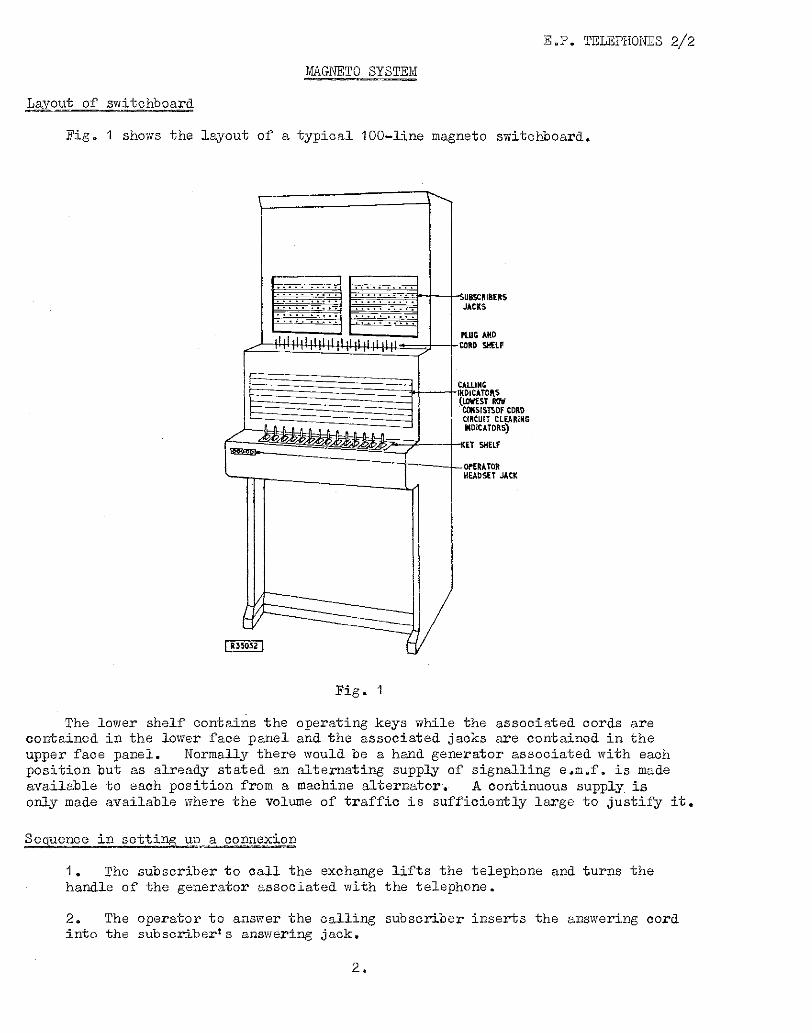
Fig. 1 shows the layout of a typical 100—line magneto switchboard.
Fig.
The lower shelf contains the operating keys while the associated cords are contained in the lower face panel and the associated jacks are contained in the upper face panel. Normally there would be a hand generator associated with each position but as already stated an alternating supply of signalling e.m.f. is made available to each position from a machine alternator. A continuous supply is only made available where the volume of traffic is sufficiently large to justify it.
Sequence in setting up a connexion
1. The subscriber to call the exchange lifts the telephone and turns the handle of the generator associated with the telephone.
2. The operator to answer the calling subscriber inserts the answering cord into the subscriber's answering jack.
2.
E.P. TELEPHONES 2/2
3. The calling subscriber's indicator flap is restored manually by the operator.
4.. The speak key associated with the answering cord circuit is thrown by the operator and the number of the wanted subscriber is requested.
5. If the wanted subscriber is connected to the same exchange, the operator inserts the calling end of the same cord circuit into the jack associated with the subscriber to be called.
6. To call the subscriber, the operator throws the ring key and connects ringing current to the required line.
7. When the called subscriber answers, the setting up of the call is complete and the operator withdraws from the circuit by restoring the speak key.
8. To operate the cord circuit supervisory indicator at the completion of the call the subscribers operate their hand generators.
9. When the cord circuit supervisory indicator flap is dropped the operator withdraws both plugs and restores the indicators.
Non-condensered and condensered exchanges
In the original magneto system supervisory signals were produced by manually operated generators. As manual switching systems developed e.g. C.B.S. and. C.B. systems, provision was made for supervisories to be transmitted to the exchange automatically by restoring and removing the handset. The new systems also possessed the property of through, signalling directly under the control of the subscriber's telephone switch springs.
The supervisory signal consists of a disconnexion at the subscriber's telephone. Since neither the cord circuit nor the subscriber's telephone circuit in the magneto system were suitable for extending a disconnexion modifications to the circuits were necessary. The circuit changes required that a direct current blocking capacitor be inserted to remove the effect of bridging apparatus across the line.
E.P. TELEPHONES 2/2
Subscriber's telephone
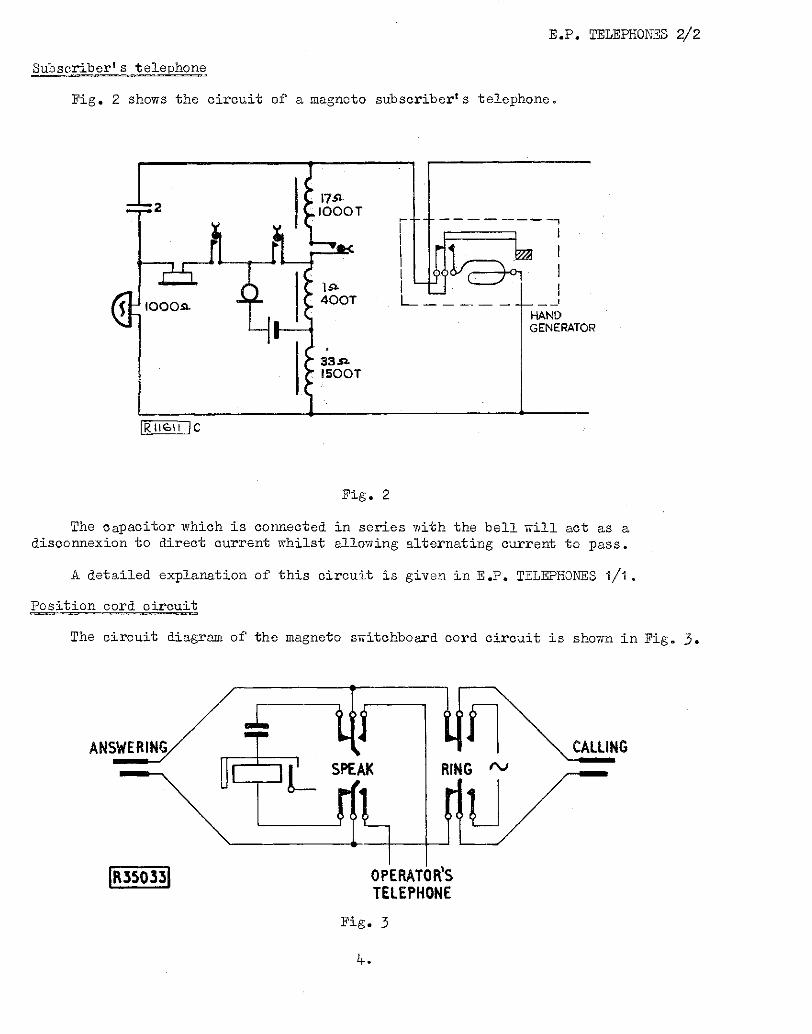
Fig. 2 shows the circuit of a magneto subscriber's telephone.
Fig. 2
The capacitor which is connected in series with the bell will act as a disconnexion to direct current whilst allowing alternating current to pass.
A detailed explanation of this circuit is given in E.P. TELEPHONES 1/1.
Position cord circuit
The circuit diagram of the magneto switchboard cord circuit is shown in Fig. 3.
Fig. 3
4..
E.P. TELEPHONES 2/2
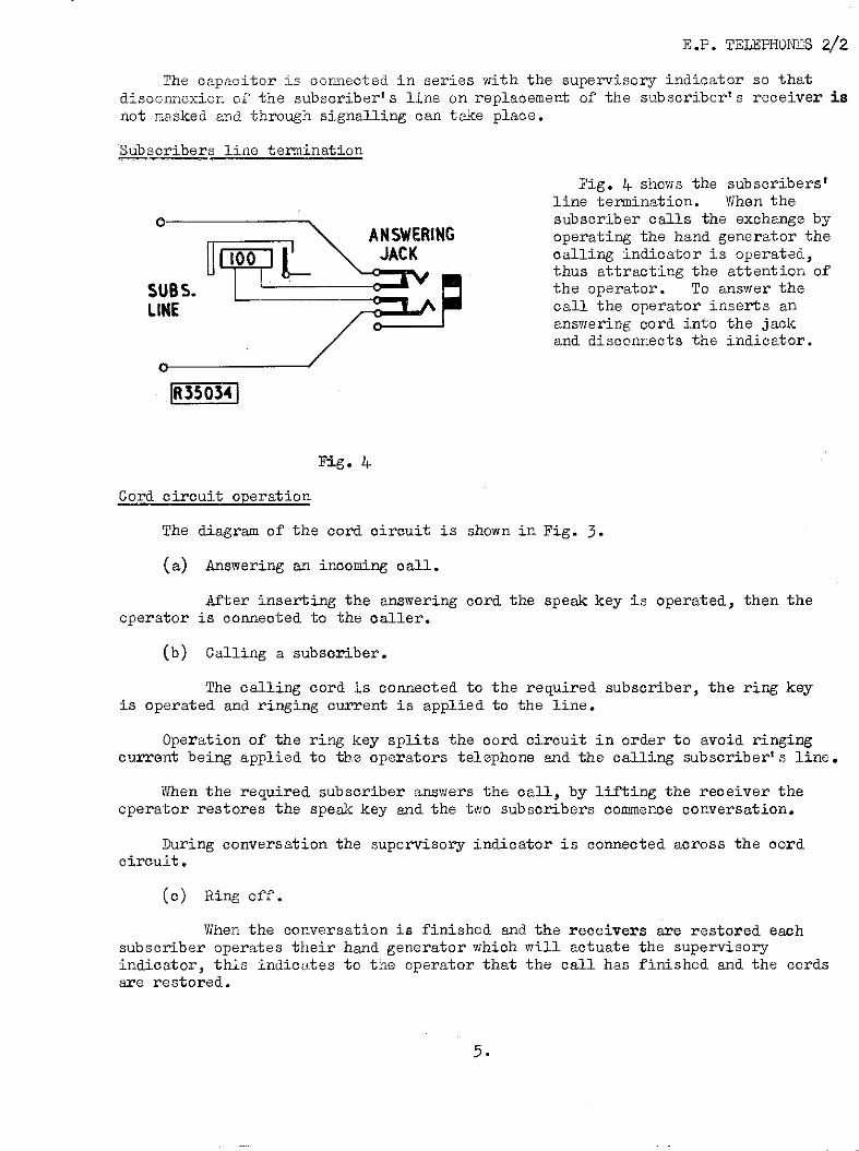
The capacitor is connected in series with the supervisory indicator so that disconnexion of the subscriber's line on replacement of the subscriber's receiver is not masked and through signalling can take place.
Subscribers line termination
Fig. 4 shows the subscribers' line termination. When the subscriber calls the exchange by operating the hand generator the calling indicator is operated, thus attracting the attention of the operator. To answer the call the operator inserts an answering cord into the jack and disconnects the indicator.
Fig. 4.
Cord circuit operation
The diagram of the cord circuit is shown in Fig. 3.
(a) Answering an incoming call.
After inserting the answering cord the speak key is operated, then the operator is connected to the caller.
(b) Calling a subscriber.
The calling cord is connected to the required subscriber, the ring key is operated and ringing current is applied to the line.
Operation of the ring key splits the cord circuit in order to avoid ringing current being applied to the operators telephone and the calling subscriber's line.
When the required subscriber answers the call, by lifting the receiver the operator restores the speak key and the two subscribers commence conversation.
During conversation the supervisory indicator is connected across the cord circuit.
(c) Ring off.
When the conversation is finished and the receivers are restored each subscriber operates their hand generator which will actuate the supervisory indicator, this indicates to the operator that the call has finished and the cords are restored.
5.
MULTIPLE
HOME SECTION
i4T81
Fig. 5
E.P. TELEPHONES 2/2
MULTIPLE SWITCHBOARD CIRCUITS
The switchboards most commonly used in small and medium sized exchanges are the 50 and 100 line boards. If, however, the requirements are such that they cannot be met by a 100 line board, then another 100 line board is installed in an adjacent position to cater for the extra lines.
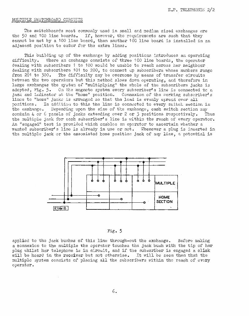
This building up of the exchange by adding positions introduces an operating difficulty. Where an exchange consists of three 100 line boards, the operator dealing with subscribers 1 to 100 would be unable to reach across her neighbour dealing with subscribers 101 to 200, to connect up subscribers whose numbers range from 201 to 300. The difficulty may be overcome by means of transfer circuits between the two operators but this method slows down operating, and therefore in large exchanges the system of "multiplying" the whole of the subscribers jacks is adopted, Fig. 5. On the magneto system every subscriber's line is connected to a jack and indicator at the "home" position. Connexion of the working subscriber's lines to "home" jacks is arranged so that the load is evenly spread over all positions. In addition to this the line is connected to every switch section in the exchange. Depending upon the size of the exchange, each switch section may contain 4 or 6 panels of jacks extending over 2 or 3 positions respectively. Thus the multiple jack for each subscriber's line is within the reach of every operator. An "engaged" test is provided which enables an operator to ascertain whether a wanted subscriber's line is already in use or not. Whenever a plug is inserted in the multiple jack or the associated home position jack of any line, a potential is
applied to the jack buR11G18of this line through-out the exchange. Before making a connexion to the multiple the operator touches the jack bush with the tip of her plug whilst her telephone is in circuit, and if the subscriber is engaged a click will be heard in the receiver but not otherwise. It will be seen then that the multiple system consists of placing all the subscribers within the reach of every operator.
6.
ANS CALL
CORD CIRCUIT
OPERATOR'S TELEPHONE CIRCUIT
A
Fig. 6
E.P. TELEPHONES 2/2
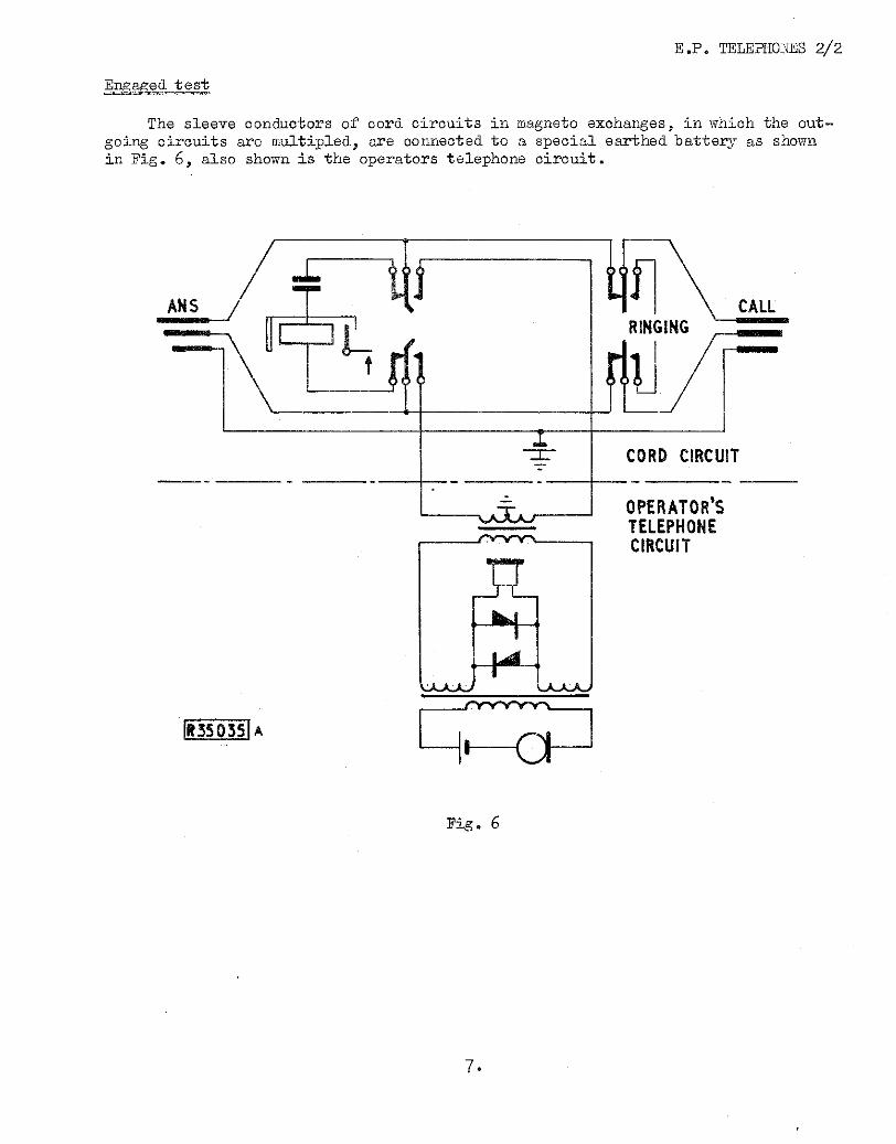
Engaged test
The sleeve conductors of cord circuits in magneto exchanges, in which the out going circuits are multipled, are connected to a special earthed battery as shown in Fig. 6, also shown is the operators telephone circuit.
7,
ITS-50361A
ENGAG;NG TIP OF PLUG TESTING PLUG
MULTIPLE
_0-71 /MIL
HOME SECTION
E.P. TELEPHONES 2/2
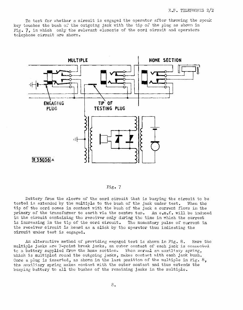
To test for whether a circuit is engaged the operator after throwing the speak key touches the bush of the outgoing jack with the tip of the plug as shown in Fig. 7, in which only the relevant elements of the cora circuit and operators telephone circuit are shown.
R 3 50361A
ENGAGINGfrom the sleeve of the cord circuit that is busying the circuit to be tested is extended by the multiple to the bush of the jack under test. When the tip of the cord comes in contact with the bush of the jack a current flows in the primary of the transformer to earth via the centre tap. An e.m.f, will be induced in the circuit containing the receiver only during the time in which the current is increasing in the tip of the cord circuit. The momentary pulse of current in the receiver circuit is heard as a click by the operator thus indicating the circuit under test is engaged.
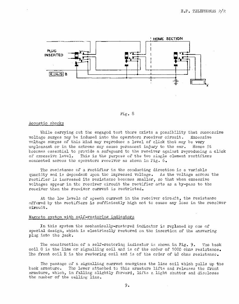
An alternative method of providing engaged test is shown in Fig. 8. Here the multiple jacks are 7—point break jacks, an outer contact of each jack is connecLed to a battery supplied from the home section. When normal an auxiliarconnected which , is multipled round the outgoing jacks, makes contact with each jack bush. Once a plug is inserted : as shown in the last position of the multiple in Fig. 8, the auxiliary spring makes contact with the outer contact and thus extends the busying battery to all the bushes of the remaining jacks in the multiple.
8.
E.P. TELEPHONES 2/2
HOME SECTION
PLUG INSERTED
R 11619 B
;AT
Fig. 8
Acoustic shocks
While carrying out the engaged test there exists a possibility that successive voltage surges may be induced into the operators receiver circuit. Excessive voltage surges of this kind may reproduce a level of click that may be very unpleasant or in the extreme may cause permanent injury to the ear. Hence it becomes essential to provide a safeguard to the receiver against reproducing a click of excessive level. This is the purpose of the two single element rectifiers connected across the operators receiver as shown in Fig. 6.
The resistance of a rectifier in the conducting direction is a variable quantity and is dependent upon the impressed voltage. As the voltage across the rectifier is increased its resistance becomes smaller, so that when excessive voltages appear in the receiver circuit the rectifier acts as a by—pass to the receiver then the receiver current is restricted.
At the low levels of speech current in the receiver circuit, the resistance offered by the rectifiers is sufficiently high not to cause any loss in the receiver circuit.
Magneto system with self—restoring indicators
In this system the mechanically—restored indicator is replaced by one of special design, which is electrically restored on the insertion of the answering plug into the jack.
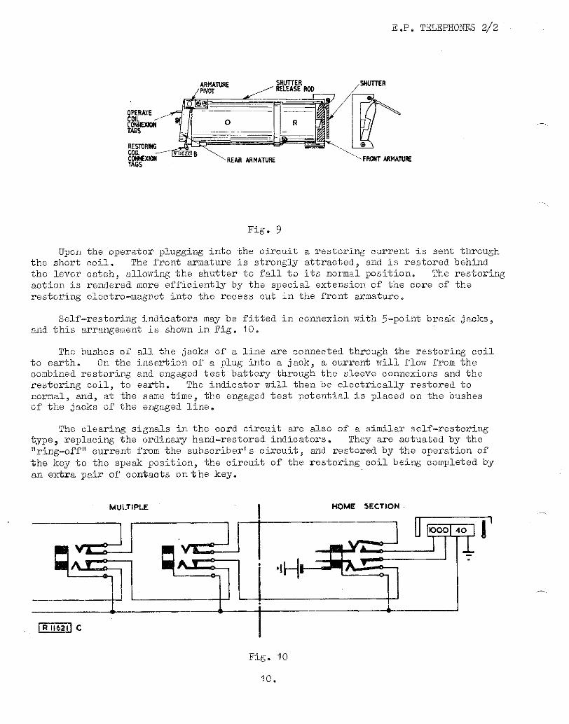
The construction of a self—restoring indicator is shown in Fig. 9. The back coil 0 is the line or signalling coil and is of the order of 1000 ohms resistance. The front coil R is the restoring coil and is of the order of 40 ohms resistance.
The passage of a signalling current energizes the line coil which pulls up the back armature. The lever attached to this armature lifts and releases the front armature, which, in falling slightly forward, lifts a light shutter and discloses the number of the calling line.
9'
OK= c
E.P. TELEPHONES 2/2
Fig. 9
Upon the operator plugging into the circuit a restoring current is sent through the short coil. The front armature is strongly attracted, and is restored behind the lever catch, allowing the shutter to fall to its normal position. The restoring action is rendered more efficiently by the special extension of the core of the restoring electromagnet into the recess cut in the front armature.
Self-restoring indicators may be fitted in connexion with 5-point break jacks, and this arrangement is shown in Fig. 100
The bushes of all the jacks of a line are connected through the restoring coil to earth. On the insertion of a plug into a jack, a current will flow from the combined restoring and engaged test battery through the sleeve connexions and the restoring coil, to earth. The indicator will then be electrically restored to normal, and, at the same time, the engaged test potential is placed on the bushes of the jacks of the engaged line.
The clearing signals in the cord circuit are also of a similar self-restoring type, replacing the ordinary hand-restored indicators. They are actuated by the "ring-off" current from the subscriber's circuit, and restored by the operation of the key to the speak position, the circuit of the restoring coil being completed by an extra pair of contacts on the key.
MULTIPLE I HOME SECTION
Fig. 10
10.
R I1622 B
Fig. 11
E.P. TELEPHONES 2/2
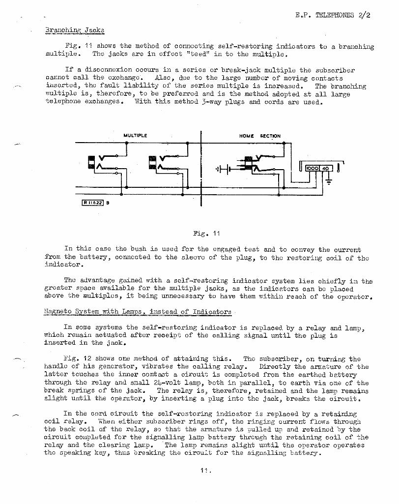
Branching Jacks
Fig. 11 shows the method of connecting self-restoring indicators to a branching multiple. The jacks are in effect "teed" in to the multiple.
If a disconnexion occurs in a series or break-jack multiple the subscriber cannot call the exchange. Also, due to the large number of moving contacts inserted, the fault liability of the series multiple is increased. The branching multiple is, therefore, to be preferred and is the method adopted at all large telephone exchanges. With this method 3-way plugs and cords are used.
MULTIPLE HOME SECTION
In this case the bush is used for the engaged test and to convey the current from the battery, connected to the sleeve of the plug, to the restoring coil of the indicator.
The advantage gained with a self-restoring indicator system lies chiefly in the greater space available for the multiple jacks, as the indicators can be placed above the multiples, it being unnecessary to have them within reach of the operator.
Magneto System with Lamps, instead of Indicators
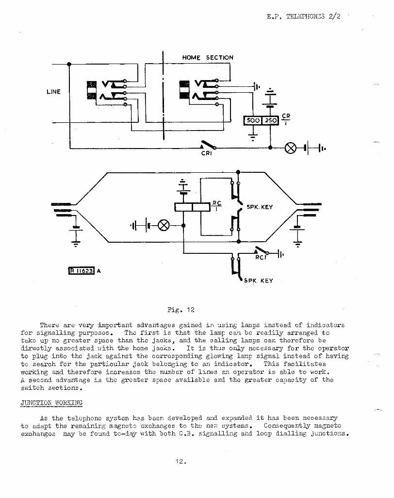
In some systems the self-restoring indicator is replaced by a relay and lamp, which remain actuated after receipt of the calling signal until the plug is inserted in the jack.
Fig. 12 shows one method of attaining this. The subscriber, on turning the handle of his generator, vibrates the calling relay. Directly the armature of the latter touches the inner contact a circuit is completed from the earthed battery through the relay and small 24-volt lamp, both in parallel, to earth via one of the break springs of the jack. The relay is, therefore, retained and the lamp remains alight until the operator, by inserting a plug into the jack, breaks the circuit.
In the cord circuit the self-restoring indicator is replaced by a retaining coil relay. When either subscriber rings off, the ringing current flows through the back coil of the relay, so that the armature is pulled up and retained by the circuit completed for the signalling lamp battery through the retaining coil of the relay and the clearing lamp. The lamp remains alight until the operator operates the speaking key, thus breaking the circuit for the signalling battery.
11,
LINE
HOME SECTION
E.P. TELEPHONES 2/2
Fig. 12
There are very important advantages gained in using lamps instead of indicators ror signalling purfores. The first is that the lamp can be readily arranged to take up no greater space than the jacks, and the calling lamps can therefore be directly associated with the home jacks. It is thus only necessary for the operator to plug into the jack against the corresponding glowing lamp signal instead of having to search for the particular jack belonging to an indicator. This facilitates Norking and therefworkingreases the number of lines an operator is able to work. second advantage is the greater space available and the greater capacity of the
switch sections.
MOTION WORKING-
As the telephone system has been developed and expanded it has been necessary to adapt the remaining magneto exchanges to the new systems. Consequently magneto exchanges may be found to—day with both C.B. signalling and loop dialling junctions.
12 .
TO LINE
E.P. TELEPHONES 2/2
Magneto signalling
The line termination on junctions using this type of signalling is the same as the subscriber's line termination, and the circuit operation is similar.
C.B. signalling
Outgoing junction
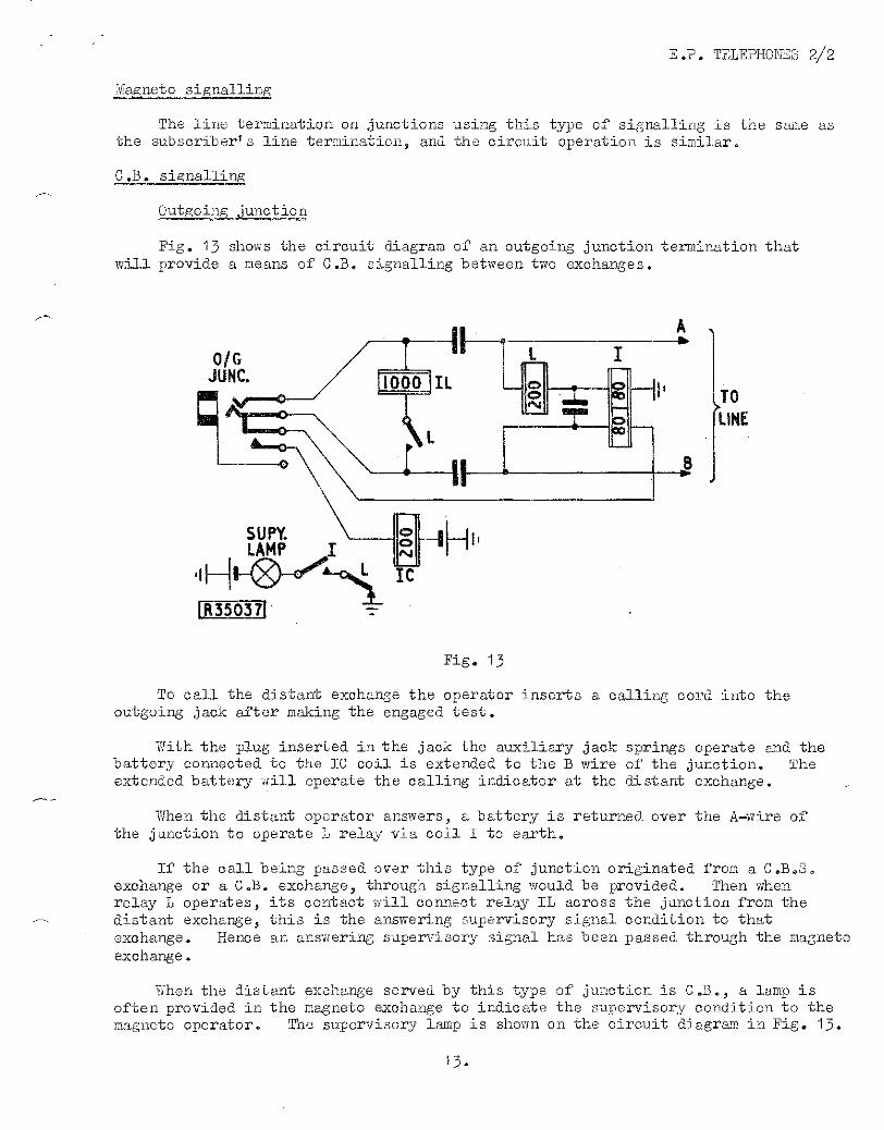
Fig. 13 shows the circuit diagram of an outgoing junction termination that will provide a means of C.B. signalling between two exchanges.
Fig. 13
To call the distant exchange the operator inserts a calling cord into the outgoing jack after making the engaged test.
With the plug inserted in the jack the auxiliary jack springs operate and the battery connected to the IC coil is extended to the B wire of the junction. The extended battery will operate the calling indicator at the distant exchange.
When the distant operator answers, a battery is returned over the A-wire of the junction to operate L relay via coil I to earth.
If the call being passed over this type of junction originated from a C.B.S. exchange or a C.B. exchange, through signalling would be provided. Then when relay L operates, its contact will connect relay IL across the junction from the distant exchange, this is the answering supervisory signal condition to that exchange. Hence an answering supervisory signal has been passed through the magneto exchange.
When the distant exchange served by this type of junction is C.B., a lamp is often provided in the magneto exchange to indicate the supervisory condition to the magneto operator. The supervisory lamp is shown on the circuit diagram in Fig. 13.
E.P. TELEPHONES
When the magneto operator calls the distant exchange the battery extended to the B wire of the junction operates the I relay. Then t distant operator answers, the battery returned over use wire of the junction operates relay L, the contact of which disconnects the supervisory lamp. Then the originating operator knows that when the supervisory lamp is extinguished, the distant operator has answered.
Incoming junction
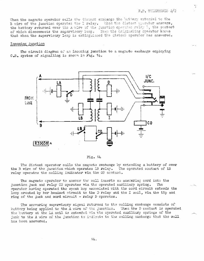
The circuit diagram of an incoming junction to a magneto exchange employing C.B. system of signalling is shown in Fig. 1 4-
FROM) UNE
Fig.
The distant., operator calls the magneto exchange by extending a battery of over the B wire of the junction which operates LB relay. The operated contact of LB relay operates the calling indicator via the CO contact.
The magneto operator to answer the call inserts an answering cord into the junction jack and relay CO operates via the operated auxiliary spring. The operator having operated the speak key associated with the cord circuit extends the loop created by her headset circuit to the D relay and the I coil, via the tip and ring of the jack and cord circuit - relay D operates.
The answering supervisory signal returned to the calling exchange consists of battery being applied to the A wire of the junction. 'Men the D contact is operated the battery at the LA coil is extended via the operated auxiliary springs of the jack to the A wire of the junction to indi c ate to the calling exchange that the call has been answered
LINE
I IC JUNC.
CALL & e CLEAR SUPY.
INDICATOR R 35039 A
DDI
FROM LINE
Fig. 15
E.P. TELEPHONES 2/2
When the junction is extended to a subscriber and the operator has withdrawn from the circuit the D relay will remain operated providing the subscriber has answered, hence the supervisory battery is maintained on the A. wire of the junction by the operated D contact.
Immediately the called subscriber restores the telephone the D relay releases and the battery is removed from the A. wire. The absence of the battery on the A. wire at the outgoing exchange will cause a lamp or indicator to operate, thus indicating to the operator that the distant subscriber has restored and the cords can also be restored.
The circuits of the C.B. signalling junction terminations shown in Figs. 13 and 1L- can be worked together to form a C.B. signalling junction. When this is done the A and B wires of one termination must be reversed. If this reversal was not included at one end of the junction the calling supervisory signals would be applied to the wrong relays.
AUTOMATIC EXCHANGE JUNCTIONS
Incoming junctions
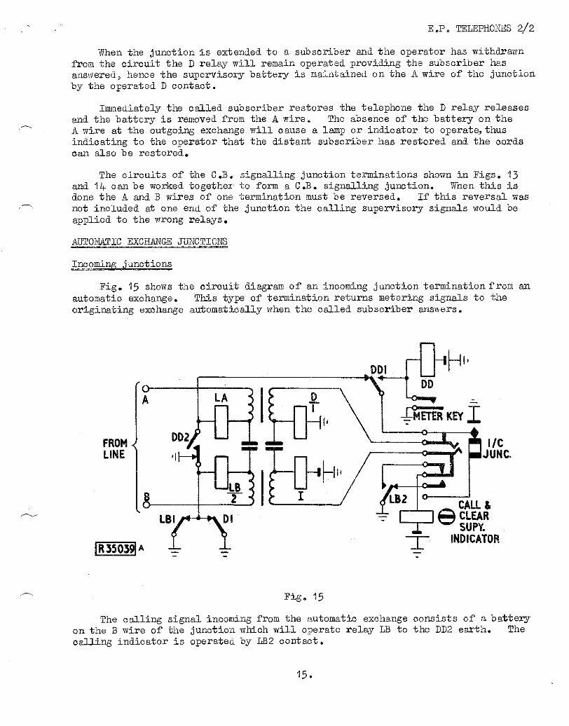
Fig. 15 shows the circuit diagram of an incoming junction termination from an automatic exchange. This type of termination returns metering signals to the originating exchange automatically when the called subscriber answers.
The calling signal incoming from the automatic exchange consists of a battery on the B wire of the junction which will operate relay LB to the DD2 earth. The calling indicator is operated by LB2 contact.
1 5.
YA = 10,000 ohms QB=QA = 2uF
FROM OPERATORS TELEPHONES
Fig. 16
16.
E.P. TELEPHONES 2/2
When the operator inserts an answering cord, the auxiliary springs of the jack operate, one set of which extends an earth via DD1 contact to the A wire of the junction to remove ring tone from the calling subscriber's line at the automatic exchange. The remaining set of auxiliary springs disconnect the calling indicator. The operator then extends the call to the required subscriber and then operates the meter key. Relay DD operates and provides an alternative holding path via its own contact DD1 to the auxiliary spring earth. Operation of contact DD2 prepares for metering to take place when the called subscriber answers, relay DD remains operated for the duration of the connexion.
When the called subscriber answers, a loop is extended to the cord circuit which operates relay D to the battery connected to coil I. Operation of contact D1 removes earth from the relays LA and LB and returns the battery, being extended over the B wire of the junction, back to the automatic exchange via LA relay which then operates. The return of battery back over the A wire of the junction constitutes answering supervisory and thus the calling subscriber's meter is operated.
When the calling subscribers' telephone is restored to normal the junction is disconnected at the automatic exchange and relays LA and LB restore. Contact LB2 then completes the circuit for the calling indicator which acts as a visible supervisory signal to the operator who can then restore the cords. Withdrawal of the plug of answering cord restores the jack auxiliary springs thus releasing the calling indicator and relay DD.
If only the called subscriber replaces the receiver relay D would release and contact DI extends earth to the A wire of the junction thus repeating clearing supervisory to the automatic exchange. Clearing supervisory is indicated to the magneto exchange operator only if the called subscriber operates the hand generator in this circumstance.
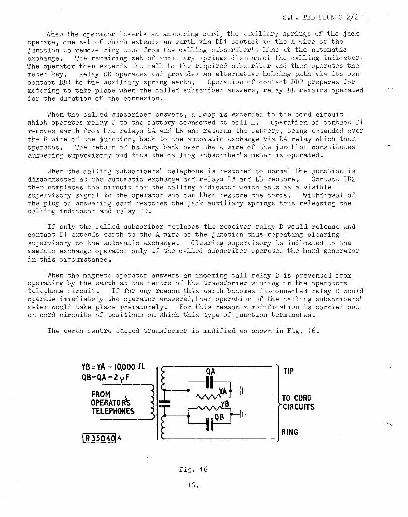
When the magneto operator answers an incoming call relay D is prevented from operating by the earth at the centre of the transformer winding in the operators telephone circuit. If for any reason this earth becomes disconnected relay D would operate immediately the operator answered, then operation of the calling subscribers' meter would take place prematurely. For this reason a modification is carried out on cord circuits of positions on which this type of junction terminates.
The earth centre tapped transformer is modified as shown in Fig. 16,
TIP TO CORD CIRCUITS
RING
E.P. TELEPHONES 2/2
When carrying out engaged test with the tip of the plug on an engaged circuit with this modified cord circuit the momentary flow of current charges capacitor QA. The resistor YA connected across the capacitor QA ensures that the capacitor is always in the discharged state prior to the test being carried out. The value of YA is sufficiently large not to have any effect on relay D in the cord circuit. In order that balance is maintained the ring of the cord circuit is similarly connected to capacitor QB and resistor YB.
The junction termination shown in Fig. 15 may be used on an incoming route that can carry calls from both automatic subscribers and manual operators via an automatic exchange. If the call being answered by the magneto operator originated at a manual exchange it is essential to return answering supervisory without making use of the termination's metering facility. Similar circumstances apply when the junction route is restricted to incoming manual traffic only. To cater for these varied circumstances special arrangements are made at the incoming junction termination.
Outgoing junction
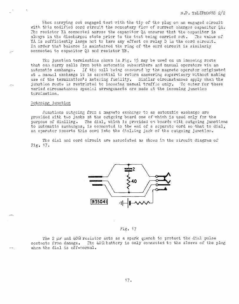
Junctions outgoing from a magneto exchange to an automatic exchange are provided with two jacks at the outgoing board one of which is used only for the purpose of dialling. The dial, which is provided on boards with outgoing junctions to automatic exchanges, is connected to the end of a separate cord so that to dial, an operator inserts this cord into the dialling jack of the outgoing junction.
The dial and cord circuit are associated as shown in the circuit diagram of Fig. 17.
Fig. 17
The 2µF and 2+0C1 resistor acts as a spark quench to protect the dial pulse contacts from damage. The 24_0(6. battery is only connected to the sleeve of the plug when the dial is off—normal.
1 7.
A 835042
DIALLING JACK
0/G JACK
SUPY.
0/G JUNC.
FOR B/W WORKING TO I/C EQUIPMENT
Fig. 18
E.P. TELEPHONES 2 2;
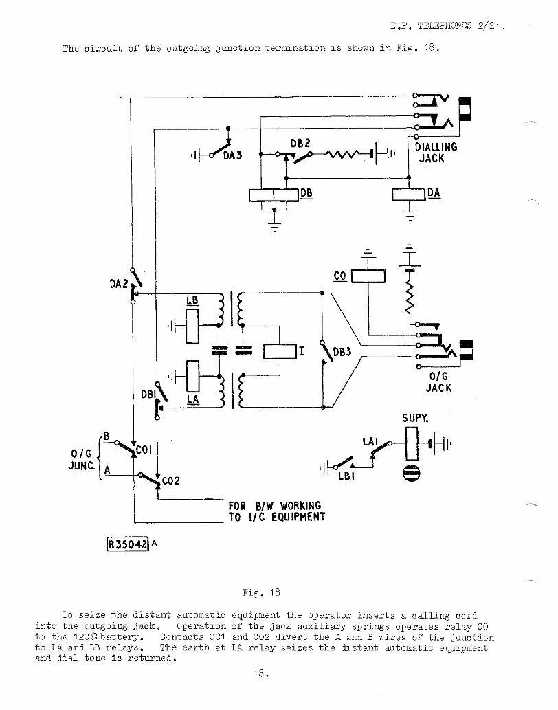
The circuit of the outgoing junction termination is shown in Fig. 18.
To seize the distant automatic into the outgoing jack. Operation to the 120Q battery. Contacts C01 to LA and LB relays. The earth at and dial tone is returned.
equipment the operator inserts a calling cord of the jack auxiliary springs operates relay CO and CO2 divert the A and B wires of the junction LA relay seizes the distant automatic equipment
18.
E.P. TELEPHONES 2/2
The dialling commences to dial is applied to the
DBI and DA2
DB 2
DB3
cord is then inserted into the dialling jack and the operator Immediately the off-normal springs of the dial operate, battery
bush of the dialling jack and. DA and DB relays opDB1te. Contacts:-
divert the A and B wires of the junction to the dial via the tip and ring of the dialling jack.
ensures that relay DB will not release until the dialling cord is withdrawn,
short circuits the tip and ring of the outgoing jack to prevent the operator LB1ring clicks as DA2 restores the B wire to the LB relay each time the dial returns to normal.
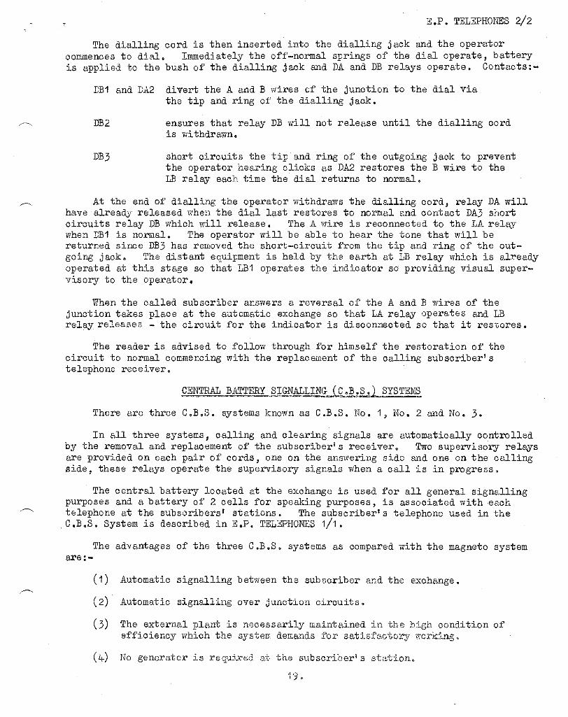
At the end of dialling the operator withdraws the dialling cord, relay DA will have already released when the dial last restores to normal and contact DA3 short circuits relay DB which will release. The A wire is reconnected to the LA relay when DBI is normal. The operator will be able to hear the tone that will be returned since DB3 has removed the short-circuit from the tip and ring of the out-going jack. The distant equipment is held by the earth at LB relay which is aC.B.Sy operated at this stage so that LBI operates the indicator so providing visual super-visory to the operator.
When the called subscriber answers a reversal of the A and. B wires of the junction takes place at the automatic exchange so that LA relay operates and. LB relay releases - the circuit for the indicator is disconnected so that it restores.
The reader is advised to follow through for himself the restoration of the circuit to normal commencing with the replacement of the calling subscriber's telephone receiver.
CENTRAL BATTERY SIGNALLING C.B.S. SYSTEMS
There are three C.B.S. systems known as C.D.S. No, 1, No. 2 and. No. 3.
In all three systems, calling and clearing signals are automatically controlled by the removal and replacement of the subscriber's receiver. Two supervisory relays are provided on each pair of cords, one on the answering side and one on the calling side, these relays operate the supervisory signals when a call is in progress.
The central battery located at the exchange is used for all genera signalling purposes and a battery of 2 cells for speaking purposes, is associated with each telephone at the subscribers' stations. The subscriber's telephone used in the C.B.S. System is described in E.P. TELEPHONES 1/1.
The advantages of the three C.B.S. systems as compared with the magneto system are:
(1) Automatic signalling between the subscriber and the exchange.
(2) Automatic signalling over junction circuits.
(3) The external plant is necessarily maintained in the high condition of efficiency which the system demands for satisfactory working.
(if) No generator is required at the subscriber's station.
1 9 .
E.P. TELEPHONES 2/2
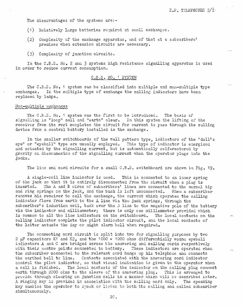
The disadvantages of the systems are:-
(1) Relatively large batteries required at small exchanges.
(2) Complexity of the exchange apparatus, and of that at a subscribers' premises when extension circuits are necessary.
(3) Complexity of junction circuits.
In the C.B.S. No 2 and 3 systems high resistance signalling apparatus is used in order to reduce current consumption.
C.B.S. NO. 1 SYSTEM
The C.B.S. No 1 system can be classified into multiple and non-multiple type exchanges. In the multiple type of exchange the calling indicators have been replaced by lamps.
Non-multiple exchanges
The C.B.S. No, I system was the first to Be introduced. The basis of signalling is "loop" call and "earth" clear. In this system the lifting of the receiver from its rest completes the circuit for current to pass through the calling device from a central battery installed in the exchange.
In the smaller switchboards of the wall pattern type, indicators of the "doll's eye" or "eyeball" type are usually employed. This type of indicator is energized and actuated by the signalling current, but is automatically self-restored by gravity on disconnexion of the signalling current when the operator plugs into the jacks.
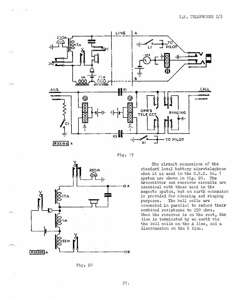
The line and cord circuits for a small C.B.S. switchboard are shown in Fig. 19.
A single-coil line indicator is used. This is connected to an inner spring of the jack so that it is entirely disconnected from the circuit when a plug is inserted. The A. and. B wires of subscribers lines are connected to the normal tip and ring springs on the jack, and the bush is left unconnected. When a subscriber removes his receiver to call the exchange, the current which operates the calling indicator flows from earth to the A line via the jack springs, through the subscriber's induction coil, back over the 2 line to the negative pole of the battery via the indicator and milliammeter; there is only one milliammeter provided which is common to all the line indicators on the switchboard. The local contacts on the calling indicator complete the pilot indicator circuit, and the local contacts of the latter actuate the day or night alarm bell when required.
The connecting cord circuit is split into two for signalling purposes by two 2 0 capacitors K1 and. K2, and the 1000 1000 ohms differentially wound eyeball indicators A and. C are bridged across the answering and calling cords respectively with their centre points connected to battery. These indicators are operated when the subscriber connected to the relevant cord hangs up his telephone and connects the earthed bell to line. Contacts associated with the answering cord indicator control the pilot indicator, so that visual indication is given to the operator when a call is finished. The local contacts of the indicator on the calling plug connect earth through 2000 ohms to the sleeve of the answering plug. This is arranged to provide through clearing on junction calls in a manner which will be described later. A ringing key is provided in association with the calling cord only. The speaking key enables the operator to sneak or listen to both the calling and called subscriber simultaneously.
20.
E.P. TELEPHONES 2/2
Fig. 19
Fig, 20
The circuit connexions of the standard local battery microtelephone when it is used in the C.B.S. No 1 system are shown in Fig. 20. The transmitter and receiver circuits are
A identical with those used in the magneto system, but an earth connexion is provided for clearing and ringing purposes. The bell coils are connected in parallel to reduce their combined resistance to 250 ohms. When the receiver is on the rest, the line is terminated by an earth via the bell coils on the A line, and a disconnexion on the B line.
21.
E.P. TELEPHONES 2/2
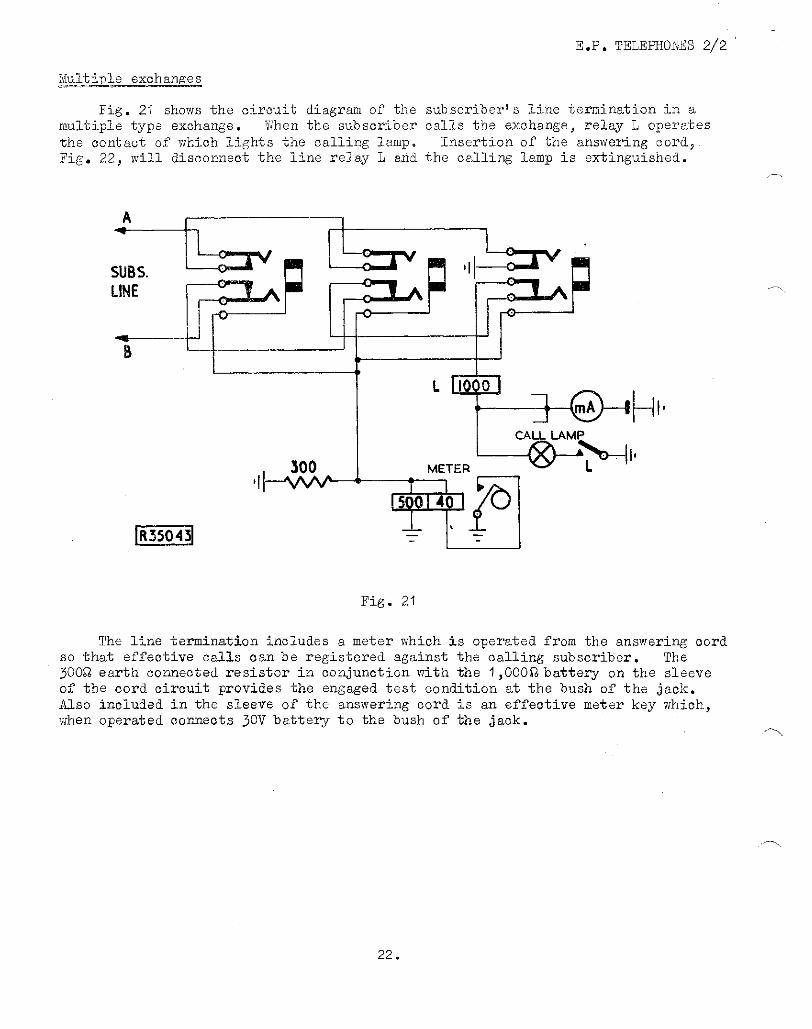
Multiple exchanges
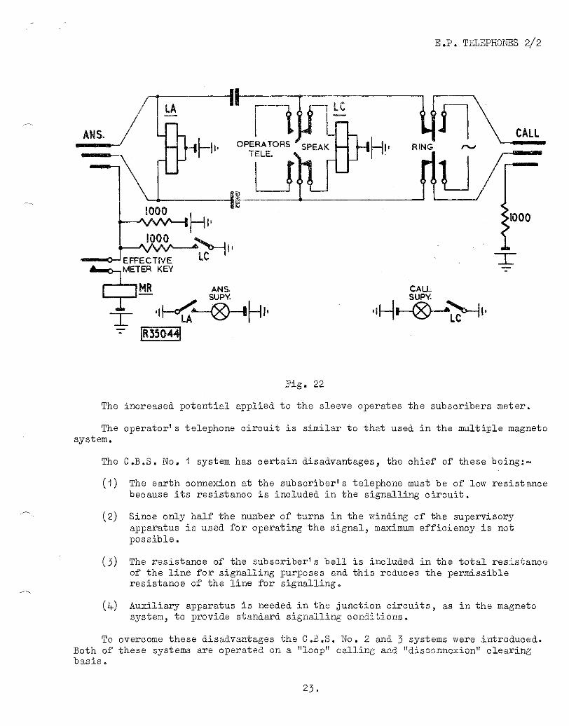
Fig. 21 shows the circuit diagram of the subscriber's line termination in a multiple type exchange. When the subscriber calls the exchange, relay L operates the contact of which lights the calling lamp. Insertion of the answering cord, Fig. 22, will disconnect the line relay L and the calling lamp is extinguished.
Fig. 21
The line termination includes a meter which is operated from the answering cord so that effective calls can be registered against the calling subscriber. The 300 earth connected resistor in conjunction with the 1 ,000Q battery on the sleeve of the cord circuit provides the engaged test condition at the bush of the jack. Also included in the sleeve of the answering cord is an effective meter key which, when operated connects 30V battery to the bush of the jack.
22.
E.P. TELEPHONES 2/2
Fig. 22
The increased potential applied to the sleeve operates the subscribers meter.
The operator's telephone circuit is similar to that used in the multiple magneto system.
The C.B.S. No. I system has certain disadvantages, the chief of these being:—
0) The earth connexion at the subscriber's telephone must be of low resistance because its resistance is included in the signalling circuit.
(2) Since only half the number of turns in the winding of the supervisory apparatus is used for operating the signal, maximum efficiency is not possible.
(3) The resistance of the subscriber's bell is included in the total resistance of the line for signalling purposes and this reduces the permissible resistance of the line for signalling.
(iv) Auxiliary apparatus is needed in the junction circuits, as in the magneto system, to provide standard signalling conditions.
To overcome these disadvantages the C.B.S. No. 2 and 3 systems were introduced. Both of these systems are operated on a "loop" calling and "disconnexion" clearing basis®
23.
E.P. TELEPHONES 2/2
JUNCTION WORKING.
Junctions between C.B.S. No 1 exchanges and other manual exchanges are usually worked on the principle of C.B. signalling. Then junctions are required between automatic exchanges and C.B.S. No exchanges the equipment and operation at the manual exchange will be very similar to that already described for junctions between automatic and magneto exchanges. If the reader is particularly concerned with junctions from C.B.S. No I to Auto exchanges then reference should be made to the Magneto System section of this pamphlet where junctions to and from automatic exchanges are discussed.
C.B. signalling
Outgoing
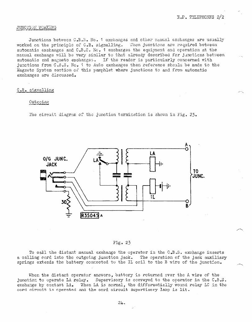
The circuit diagram of the junction termination is shown in Fig. 23.
Fig, 23
To call the distant manual exchange the operator in the C.B.S. exchange inserts a calling cord into the outgoing junction jack. The operation of the jack auxiliary springs extends the battery connected to the IL coil to the B wire of the junction.
When the distant operator answers, battery is returned over the A wire of the junction to operate LA relay. Supervisory is conveyed to the operator in the C.B.S. exchange by contact LA. When LA is normal, the differentially wound relay LC in the cord circuit is operated and the cord circuit supervisory lamp is lit.
E.P. TELEPHONES 2/2
Incoming
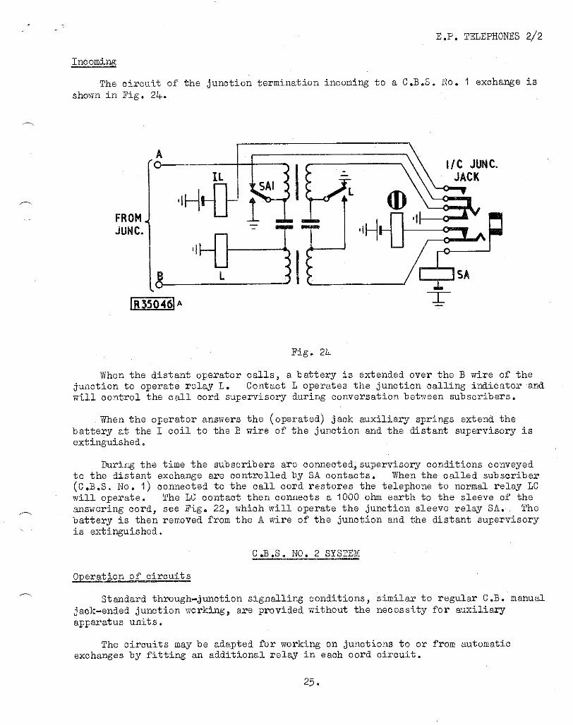
The circuit of the junction termination incoming to a C.B.S. No. 1 exchange is shown in Fig. 24.
Fig. 24
When the distant operator calls, a battery is extended over the B wire of the junction to operate relay L. Contact L operates the junction calling indicator and will control the call cord supervisory during conversation between subscribers.
When the operator answers the (operated) jack auxiliary springs extend the battery at the I coil to the B wire of the junction and the distant supervisory is extinguished.
During the time the subscribers are connected,supervisory conditions conveyed to the distant exchange are controlled by SA contacts. When the called subscriber (C.B.S. No. 1) connected to the call cord restores the telephone to normal relay LC will operate. The LC contact then connects a 1000 ohm earth to the sleeve of the answering cord, see Fig. 22, which will operate the junction sleeve relay SA. The battery is then removed from the A wire of the junction and the distant supervisory is extinguished.
C.B.S. NO. 2 SYSTEM
Operation of circuits
Standard through-junction signalling conditions, similar to regular C.B. manual jack-ended junction working, are provided without the necessity for auxiliary apparatus units.
The circuits may be adapted for working on junctions to or from automatic exchanges by fitting an additional relay in each cord circuit.
25.
E.P. TELEPHONES 2/2
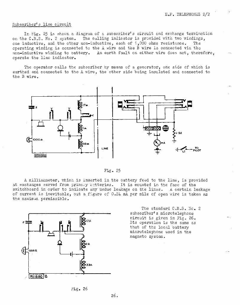
Subscriber's line circuit
In Fig. 25 is shown a diagram of a subscriber's circuit and exchange termination on the C.B.S. No. 2 system. The calling indicator is provided with two windings, one inductive, and the other non-inductive, each of 1,000 ohms resistance. The operating winding is connected to the A wire and the B wire is connected via the non-inductive winding to battery. An earth fault on either wire does not, therefore, operate the line indicator.
The operator calls the subscriber by means of a generator, one side of which is earthed and connected to the A wire, the other side being insulated and connected to the B wire.
Fig. 25
A milliammeter, which is inserted in the battery feed to the line, is provided at exchanges served from primary batteries. It is mounted in the face of the switchboard in order to indicate any undue leakage on the lines. A certain leakage of current is inevitable, but a figure of 0.24 mA per mile of open wire is taken as the maximum permissible.
The standard C.B.S. No. 2 subscriberlssubscriber'sone circuit is given in Fig. 26. Its operation is the same as that of the local battery microtelephone used in the magneto system.
Fig. 26
26.
E.P. TELEPHONES 2/2
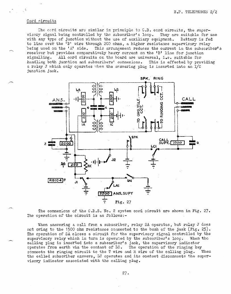
Cord circuits
The cord circuits are similar in principle to C.B. cord circuits, the super-visory signal being controlled by the subscriber's loop. They are suitable for use with any type of junction without the use of auxiliary equipment. Battery is fed to line over the 1 72' wire through 200 ohms, a higher resistance supervisory relay being used on the 'Al side. This arrangement reduces the current in the subscriber's receiver but provides comparatively heavy current on the 'B' line for junction signalling. All cord circuits on the board are universal, i.e. suitable for handling both junction and subscribers' connexions. This is effected by providing a relay J which only operates when the answering plug is inserted into an VC junction jack.
Fig. 27
The connexions of the C.B.S. No. 2 system cord circuit are shown in Fig. 27. The operation of the circuit is as follows:-
When answering a call from a subscriber, relay SA operates, but relay J does not owing to the 1500 ohm resistance connected to the bush of the jack (Fig. 25). The operation of SA closes a circuit for the supervisory signal controlled by the supervisory relay which in turn is operated by the subscriber's loop. When the calling plug is inserted into a subscriber's jack, the supervisory indicator operates from earth via the contact of LC. The operation of the ringing key connects the ringing circuit to the T wire and R wire of the calling plug. When the called subscriber answers, LC operates and its contact disconnects the super-visory indicator associated with the calling plug.
27.
E.P. TELEPHONES 2/2
When both subscribers replace their receivers relays LA and LC release and complete the circuit for their respective supervisory signals. A contact associated with the answering supervisory indicator operates the pilot indicator and, on receiving this clearing signal, the operator clears down the connexion.
The 2 g capacitors connected across relay J and the call supervisory coil are provided so that the operator will not receive shocks while operating. As will be explained later relay J operates only when the cord is used to answer an incoming junction call. The capacitor also ensures that relay J only operates in the correct circumstances and not to surges of voltages.
JUNCTION WORKING
C.B. signalling
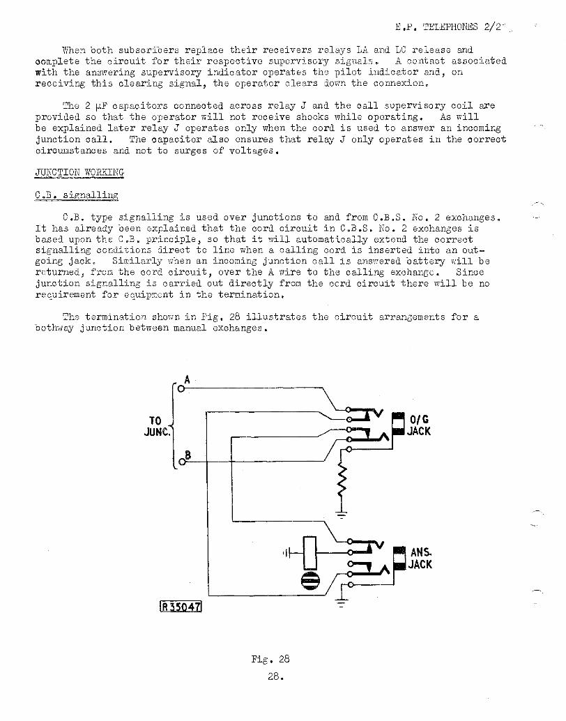
C.B. type signalling is used over junctions to and from C.B.S. No. 2 exchanges. It has already been explained that the cord circuit in C.B.S. No. 2 exchanges is based upon the C.B. principle, so that it will automatically extend the correct signalling conditions direct to line when a calling cord is inserted into an out-going jack. Similarly when an incoming junction call is answered battery will be returned, from the cord circuit, over the A wire to the calling exchange. Since junction signalling is carried out directly from the cord circuit there will be no requirement for equipment in the termination.
The termination shown in Fig. 28 illustrates the circuit arrangements for a bothway junction between manual exchanges.
0/ G JACK
ANS. JACK
E.P. TELEPHONES 2/2
The incoming jack of the junction will be that jack associated with the calling indicator. The connexions to the jack are so arranged that when:-
(I) An outgoing call is originated the calling cord extends battery over the B wire of the junction and,
(2) An incoming call is answered the answering cord will extend battery over the A wire of the junction. Hence, this explains the necessity for the reversal in the connexion between the answer and call jacks of the junction.
Now consider an incoming call being answered. On insertion of the answering cord, Fig. 27, the sleeve re .ay J operates to the full earth on the bush of the jack. Relay SA also operates momentarily but cannot hold since contact J1 is operated. The answer supervisory will be operated by contact SA1 and held by contact J1 (operated) when contact SA1 restores to normal. When the answering operator throws the speak key, battery is extended over the A wire of the junction, from the speak key auxiliary springs, to provide the answer supervisory signal to the calling operator. Contact J2 ensures that the answer supervisory is only returned to the calling exchange when the speak key is operated.
When the incoming call has been extended to the called subscriber and the operator has restored the speak key, supervisory returned to the originating exchange is controlled by contact LC1 directly under the control of the called subscriber.
When an outgoing call is originated by the C.B.S. exchange operator, battery is extended to the B wire of the junction from the IC coil in the cord circuit.
Automatic exchange junctions
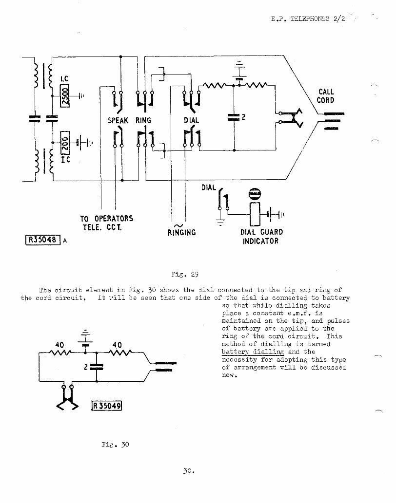
The switchboard cord circuit in C.B.S. No. 2 exchanges, Fig. 27, will have to be modified before dialling is made possible. The relevant portion of the cord circuit illustrating the method of connecting the dial and dial key is shown in Fig. 29.
There will only be one dial key per position and it is connected in such a manner that when it is operated the ringing current will be disconnected from all the ring keys on the board. To connect the dial to the tip and ring of the cord circuit both the ring and dial keys must be operated. So that misoperation will not occur the ring key is of the non-locking type and an auxiliary contact of the dial key is connected to a visual indicator to guard against omission to restore the dial key.
29.
E.P. TELEPHONES 2/2
Fig. 25
The circuit element in Fig. 30 shows the dial connected to the tip and ring of the cord circuit. It will be seen that one side of the dial is connected to battery
so that while dialling takes place a constant e.m.f. is maintained on the tip, and pulses of battery are applied to the ring of 'the cord circuit. This method of dialling is termed battery dialling and the necessity for adopting this type of arrangement will be discussed now.
Fig. 30
30.
E.P. TELEPHONES 2/2
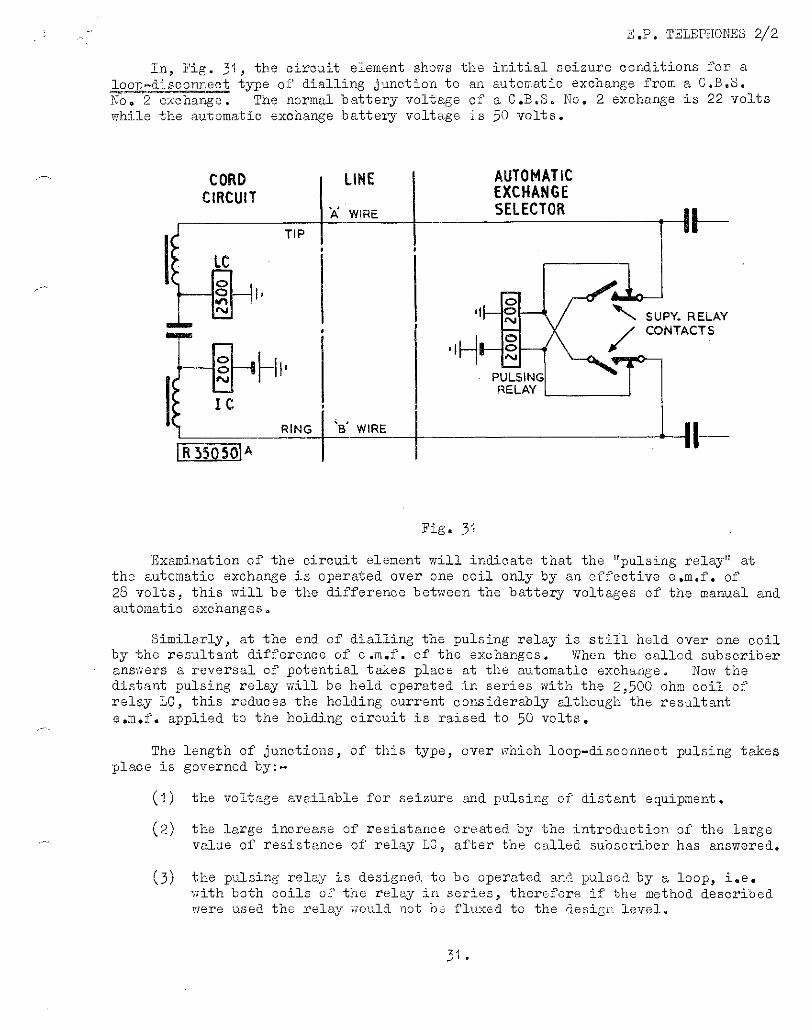
In, Fig. 31, the circuit element shows the initial seizure conditions for a loop-disconnect type of dialling junction to an automatic exchange from a C.B.S.
No. 2 exchange. The normal battery voltage of a C.B.S. No. 2 exchange is 22 volts while the automatic exchange battery voltage is 50 volts.
Fig. 31
Examination of the circuit element will indicate that the "pulsing relay" at the automatic exchange is operated over one coil only by an effective e.m.f. of 28 volts, this will be the difference between the battery voltages of the manual and automatic exchanges.
Similarly, at the end of dialling the pulsing relay is still held over one coil by the resultant difference of e.m.f. of the exchanges. When the called subscriber answers a reversal of potential takes place at the automatic exchange. Now the distant pulsing relay will be held operated in series with the 2,500 ohm coil of relay LC, this reduces the holding current considerably although the resultant e.m.f. applied to the holding circuit is raised to 50 volts.
The length of junctions, of this type, over which loop-disconnect pulsing takes place is governed by:-
(1) the voltage available for seizure and pulsing of distant equipment.
(2) the large increase of resistance created by the introduction of the large value of resistance of relay LC, after the called subscriber has answered.
(3) the pulsing relay is designed to be operated and pulsed by a loop, i.e. with both coils of the relay in series, therefore if the method described were used the relay would not be fluxed to the design level.
3 1
I L
R35051
MANUAL EXCHANGE A
G
PULSING RELAY
Fig. 32
AUTOMATIC EXCHANGE LINE
E.P. TELEPHONES 2/2
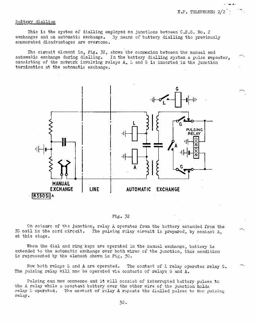
Battery dialling
This is the system of dialling employed on junctions between C.B.S. No. 2 exchanges and an automatic exchange. By means of battery dialling the previously enumerated disadvantages are overcome.
The circuit element in, Fig. 32, shows the connexion between the manual and automatic exchange during dialling. In the battery dialling system a pulse repeater, consisting of the network involving relays A, L and G is inserted in the junction termination at the automatic exchange.
On seizure of the junction, relay A operates from the battery extended from the IC coil in the cord circuit. The pulsing relay circuit is prepared, by contact A, at this stage.
When the dial and ring keys are operated in the manual exchange, battery is extended to the automatic exchange over both wires of the junction, this condition is represented by the element shown in Fig. 30.
Now both relays L and A are operated. The contact of L relay operates relay G. The pulsing relay will now be operated via contacts of relays G and A.
Pulsing can now commence and it will consist of interrupted battery pulses to the A relay while a constant battery over the other wire of the junction holds relay L operated. The oontaot of relay A repeats the dialled pulses to the pulsing relay.
32.
E.P. TELEPHONES 2/2
C.B.S. NO, 3 SYSTEM
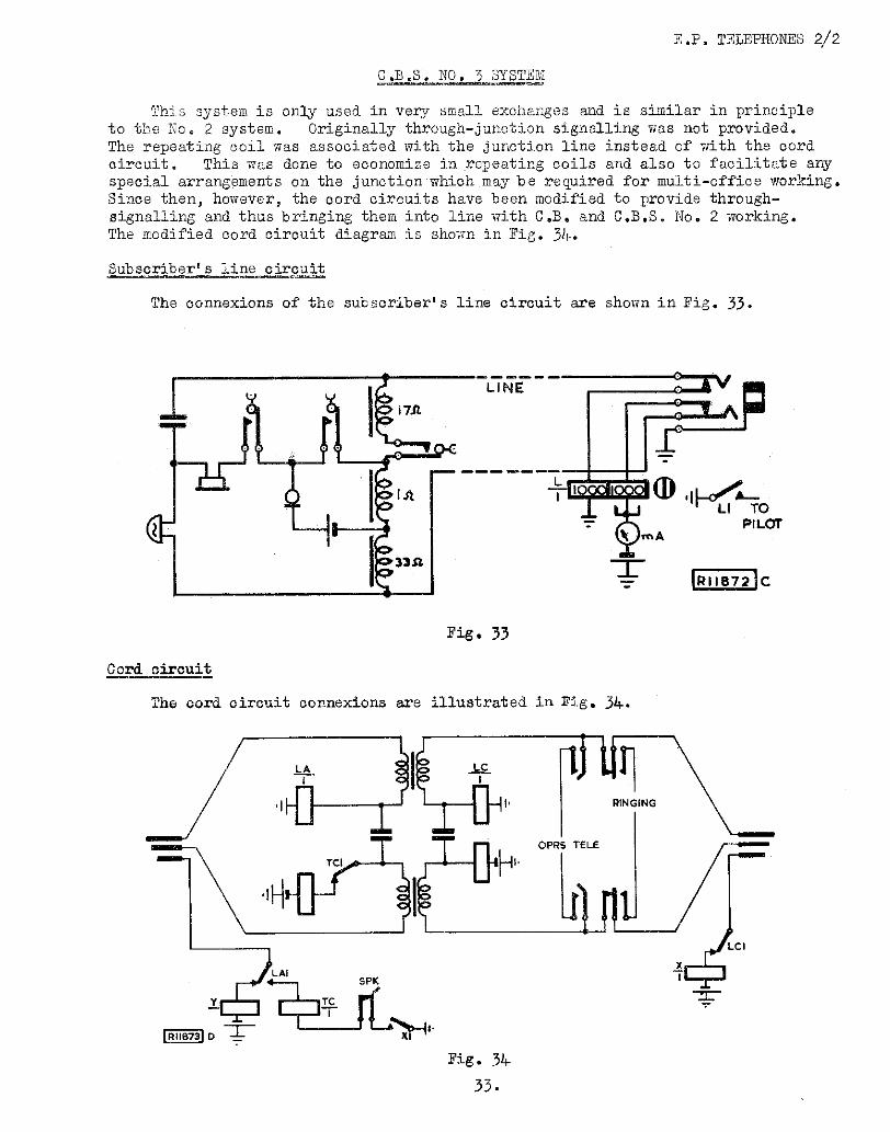
This system is only used in very small exchanges and is similar in principle to the No 2 system. Originally through-junction signalling was not provided. The repeating coil was associated with the junction line instead of with the cord circuit. This was done to economize in repeating coils and also to facilitate any special arrangements on the junction which may be required for multi-office working. Since then, however, the cord circuits have been modified to provide through-signalling and thus bringing them into line with C.B. and. C.B.S. No 2 working. The modified cord circuit diagram is shown in Fig. 3k.
Subscriber' line circuit
The connexions of the subscriber's line circuit are shown in Fig. 33.
Fig. 33
Cord circuit
The cord circuit connexions are illustrated in Fig. 34.
Fig. 34
33.
E.P. TELEPHONES 2/2
When answering a call from a subscriber, LA operates from the subscriber's loop and at LA1 disconnects the answering supervisory indicator Y The called subscriber is rung in the usual way and, until he answers, the calling supervisory indicator X is operated via LC1 normal to the earth on the bush of the jack, When the called party answers LC operates to the subscriber's loop and at LC1 disconnects the calling supervisory indicator, At the conclusion of the call both receivers are replaced and LA and LC restoring reconnect the answering and calling supervisory indicators which operate and give the clearing signals. The connexion is then taken down and the circuit is restored to normal.
The function of relay TO is to provide through-signalling on junction calls. When the called subscriber clears, relay LC releases and at LC1 reconnects the indicator I which operates. Contact X1 completes the circuit for the operation of TO, which at TC1 disconnects the battery from the ring wire of the answering cord and thus gives the clearing signal to the distant exchange.
END OF PAMPHLET
REFERENCES:- E.P. - Draft Series TELEPHONES I/1
34.