Embed Size (px)
DESCRIPTION
Magnetism. The density of a magnetic field (number of magnetic lines passing through a given surface) is the magnetic flux:. Units of flux are Webers. Tesla/m 2. Sources of Magnetism. Solenoid: Produces lines of flux as shown (in blue). - PowerPoint PPT Presentation
Citation preview

MagnetismThe density of a magnetic field (number of magnetic lines passing
through a given surface) is the magnetic flux:
SdBB
Units of flux are Webers. Tesla/m2

Sources of Magnetism
Solenoid: Produces lines of flux as shown (in blue).
Note that the magnetic field lines are continuous with no source or sink

Inside the solenoid the magnetic flux density is:
InB Where n = number of turns of wire.
= permeability of the core material.I = current through the core.
There are permanent magnets (ferromagnets) too; these are very useful for small compact sensors.
Active solenoids have many uses in sensor technologies.
Solenoids make inductive sensors which can be used to detect motion, displacement, position, and magnetic quantities.

Permanent Magnets
Residual inductance (B) in Gauss – how strong the magnet is
Coercive force (H) in Oersteds -Resistance to demagnetization
Maximum Energy Product (MEP), (B x H) in gauss-oersteds times 10^6. The overall figure of merit for a magnet
Temperature coefficient %/°C, how much the magnetic field decreaes with temperature.
There are four main ways to characterise permanent magnets:

Some common permanent magnets.

Photos of flux gate magnetometers, used for sensing magnetic fields
down to a few microtesla, which is about the size of the earth’s magnetic field.
Magnetic Induction
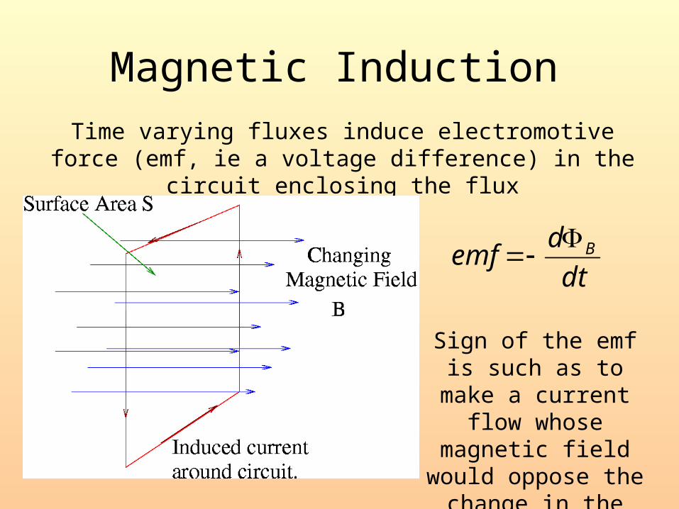
Time varying fluxes induce electromotive force (emf, ie a voltage difference) in the circuit enclosing the flux
dt
demf B
Sign of the emf is such as to make a current flow whose magnetic
field would oppose the change in the flux.

We can also plot magnetisation instead of flux density to get a similar hysteresis curve.


Some rare earth magnets-notice how the small
spheres are strong enough magnets to support the
weight of the heavy tools.

These structures were created by the action of rare earth magnets on a suspension of magnetic particles (a ferrofluid).

Hard disk reading heads use permanent magnets.
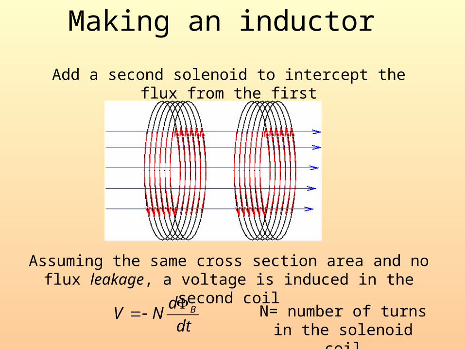
Add a second solenoid to intercept the flux from the first
Assuming the same cross section area and no flux leakage, a voltage is induced in the second coil
dt
dNV B
N= number of turns in the solenoid coil
Making an inductor

Assuming B is constant over area A gives a more useful relation :
dt
BAdNV
)(
This second coil is called the pickup circuit. We get a signal in this circuit if the magnitude of the magnetic field (B) changes or if the area of the circuit (A) changes.
We get an induced voltage if we:
• Move the source of the magnetic field (magnet, coil etc.)
• Vary the current in the coil or wire which produces the magnetic field
• Change the orientation of the magnetic field in the source
• Change the geometry of the pickup circuit, (eg. stretching or squeezing)

Example: Motion Sensor.
Pickup coil with N turns, moves into the gap of a permanent magnet
Blxb Flux enclosed by the loop is:
The induced voltage is:
nBlvdt
dxnBlBLx
dt
dN
dt
dV B
)(

Example: recording tape
http://www.research.ibm.com/research/demos/gmr/index.html

Self Induction.
The magnetic field generated by a coil also induces an emf in itself. This voltage is given by: dt
ndV B )(
The number in parenthesis is called the flux linkage, and is proportional to the current in the coil.
Lin B
The constant of proportionality is labeled the inductance, L.
dt
diL
dt
ndV B
)(
We can therefore define the inductancedtdiV
L

Induction notes.
dtdiV
L The defining equation is:
Induced voltage is proportional to current change
Voltage is zero for DC (inductors look like short circuit to DC)
Voltage increases linearly with rate of change of coil current
Voltage polarity different for increased and decreased current in same direction
Induced Voltage in direction which acts to oppose change in current
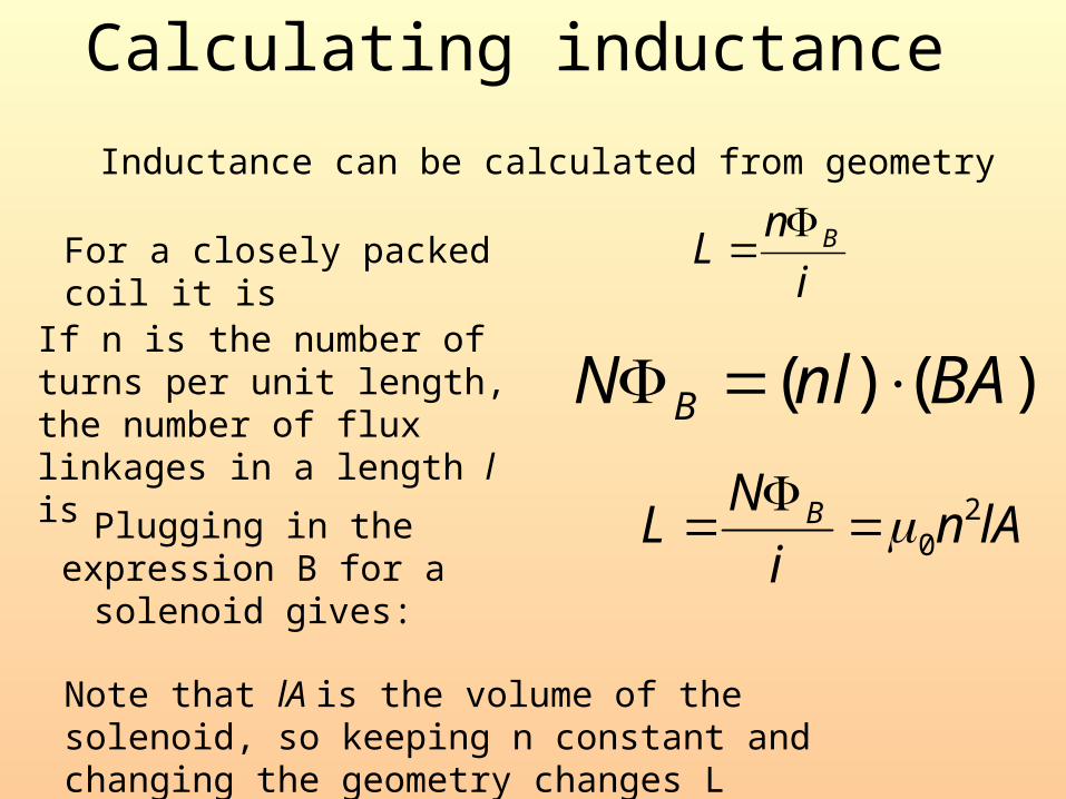
Inductance can be calculated from geometry
For a closely packed coil it isi
nL B
If n is the number of turns per unit length, the number of flux linkages in a length l is
)()( BAnlN B
Plugging in the expression B for a solenoid gives:
lAni
NL B 2
0
Note that lA is the volume of the solenoid, so keeping n constant and changing the geometry changes L
Calculating inductance

In an electronic circuit, inductance can be represented as
complex resistance, like capacitance.
Lji
V
i(t) is a sinusoidal current having a frequency =2f
Two coils brought near each other one coil induces an emf in the other dt
diMV 1
212
Where M21 is the coefficient of mutual inductance between the coils.
Inductors and complex resistance

Mutual inductance.
For a coil placed around a long cylinder: nNRM 2
0
For a coil placed around a torus, mutual inductance is
)ln(2
210
a
bhNNM

Hall Effect.
When an electron moves through a magnetic field it
experiences a sideways force:
qvBF
Q is the electron charge, v is the electron velocity, B the magnetic
field
This gives rise to an potential difference across an appropriate
sensor.

The direction of the current and magnetic fields is vital in determining size of the potential difference.
The deflecting force shifts the electrons in
the diagram to the right side.
This deflection produces the transverse Hall potential VH
Qualitative Hall effect
qvB=qE=qVH/w
v=I/neA
vH=IBL/enA
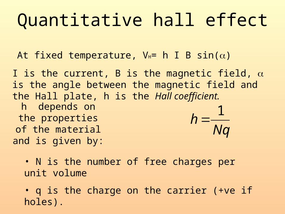
At fixed temperature, VH= h I B sin()
I is the current, B is the magnetic field, is the angle between the magnetic field and the Hall plate, h is the Hall coefficient.
h depends on the properties of the material
and is given by: Nqh
1
• N is the number of free charges per unit volume
• q is the charge on the carrier (+ve if holes).
Quantitative hall effect

Example
• A Cu strip of cross sectional area 5.0 x 0.02 cm carries a current of 20A in a magnetic field of 1.5T. What is the Hall voltage?
• Ans = 11 V, so a small effect!
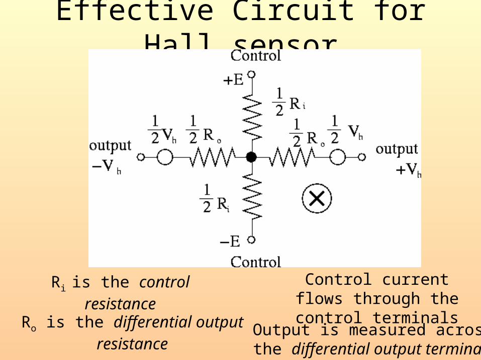
Effective Circuit for Hall sensor
Ri is the control resistance
Ro is the differential output resistance
Control current flows through the control terminals
Output is measured across the differential output terminals

Hall effect sensors are almost always Semiconductor devices.
Control Current 3 mAControl Resistance, Ri 2.2 k OhmsControl Resistance, Ri vs Temperature 0.8%/CDifferential Output Resistance, Ro 4.4 K OhmsOutput offset Voltage 5.0 mV (at B=0 Gauss)Sensitivity 60 micro-Volts/GaussSensitivity vs Temperature 0.1%/COverall Sensitivity 20 V/Ohm-kGaussMaximum B Unlimited
Parameters of a Typical sensor.
Note the significant temperature sensitivity.
Piezoresistance of silicon should be remembered; makes
semiconductor sensors very sensitive to shocks.
Also note need to use a constant current source for control.


![L 28 Electricity and Magnetism [5] magnetism magnetic forces applications](https://img.pdfslide.us/doc/110x75/56649db65503460f94aa8390/l-28-electricity-and-magnetism-5-magnetism-magnetic-forces-applications.jpg)