Embed Size (px)
Citation preview
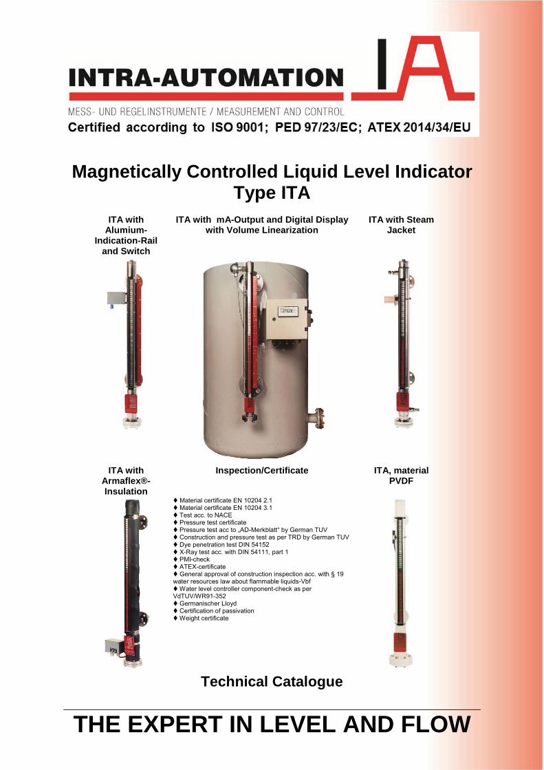
THE EXPERT IN LEVEL AND FLOW
Magnetically Controlled Liquid Level IndicatorType ITA
ITA with Alumium-
Indication-Rail and Switch
ITA with mA-Output and Digital Display with Volume Linearization
ITA with Steam Jacket
ITA with Armaflex®-Insulation
Inspection/Certificate ITA, material PVDF
Material certificate EN 10204 2.1Material certificate EN 10204 3.1Test acc. to NACEPressure test certificatePressure test acc to „AD-Merkblatt“ by German TUVConstruction and pressure test as per TRD by German TUVDye penetration test DIN 54152X-Ray test acc. with DIN 54111, part 1PMI-checkATEX-certificateGeneral approval of construction inspection acc. with § 19
water resources law about flammable liquids-VbfWater level controller component-check as per
VdTUV/WR91-352Germanischer LloydCertification of passivationWeight certificate
Technical Catalogue
Technical Catalogue ITA magnetically controlled liquid level indicator Intra-Automation
1. 1
2. 22.1 22.2 22.3 32.4 32.5 32.6 42.7 42.8 42.9 42.10 5
3. 63.1.1 63.1.2 83.1.3 103.1.4 113.2.1 193.2.2 213.3.1 283.3.2 303.4.1 373.4.2 393.5.1 443.5.2 463.6.1 503.6.2 523.6.3 543.7.1 583.7.2 603.7.3 623.8.1 673.8.2 693.8.3 713.9.1 763.9.2 783.9.3 793.9.4 813.10.1 893.10.2 913.11.1 963.11.2 983.12.1 1033.12.2 1053.12.3 1073.12.4 1083.13.1 1153.13.2 117
List of Contents
Order codes for ITA-8.1
ITA-7ITA-7.0
ITA-6.0
Order codes for ITA-7 & ITA-7.0ITA-8.1 (PVC)
ITA-6 Cryo (cryogenic applications)Order codes for ITA-6 CryoITA-6 CR64 (cryogenic applications)Order codes for ITA-6 CR64
Pressure-Temperature Table ITA-6 (Float pipe)
Pressure-Temperature Table ITA-7 (Float pipe)
ITA-4.1.0Order codes for ITA-4.1 & ITA-4.1.0ITA-5ITA-5.0Oder codes for ITA-5 & ITA-5.0ITA-6
Order codes for ITA-6 & ITA-6.0
ITA-3.8Order codes for ITA-3.8ITA-4ITA-4.0Order codes for ITA-4 & ITA-4.0ITA-4.1
ITA-3 Cryo (cryogenic applications)Order codes for ITA-3 CryoITA-3-CR64 (cryogenic applications)Order codes for ITA-3 CR64ITA-3.5Order codes for ITA-3.5
MaterialsSpecial versions
ITA-3.0
Order codes for ITA-3 & ITA-3.0
Level gauges in detailsITA-3
Additional equipmentAcceptance tests and certificates
Pressure-Temperature Table ITA-3 (Float pipe)
Functioning and General Information
ISO 9001-certificate
FloatsIndication rails
Magnetically controlled liquid level gauge type ITALevel measurement tasksAdvantagesSwitches and alarm contacts
Technical Catalogue ITA magnetically controlled liquid level indicator Intra-Automation
3.14.1 1203.14.2 1223.15.1 1253.15.3 1283.16.1 1303.16.2 1323.17.1 1343.17.2 1363.18.1 1383.18.2 1403.19.1 1423.19.2 1443.19.3 1463.19.4 1473.20.1 1543.20.2 1563.20.3 1583.20.4 1593.21.1 1663.21.2 1683.21.3 1703.21.4 1713.22.1 1783.22.2 1803.22.3 1823.22.3 183
4. 1904.1 1904.2 1914.3 1924.4 1934.5 1954.6 1974.7 1984.8 1994.9 2004.10 2034.10 205
5. 2335.1 2335.2 237
216220221230
Magnetostrictive level transmitterTransmitter
ITA-T1SSpecial constructions
Technical data switchesContact NJ-EXIndication rails
Digital Indication with mag. Level Gauges type ITA and Reed Chain
ITA-T1R
For documentation
(behind each subchapter of chapter 3)For mag. level gauges
For add. EquipmentFor special designsFor spare parts
Order codes:
Reed-contact
Armaflex -insulationHeat insulation
Equipment
Order codes for ITA-12 & ITA-12.0ITA-13ITA-13.0
ITA-3 Cryo, ITA-3 CR64
Order codes for ITA-13 & ITA-13.0Pressure-Temperature Table ITA-13 (Float pipe)
Order codes for ITA-10 & ITA-10.0ITA-11ITA-11.0
Order codes for ITA-11 & ITA-11.0
Pressure-Temperature Table ITA-10 (Float pipe)
Niveau-source
Pressure-Temperature Table ITA-11 (Float pipe)
Pressure-Temperature Table ITA-12 (Float pipe)
Order codes for ITA-8.3
ITA-12ITA-12.0
Order codes for ITA-9.1ITA-9.2 (PP)Order codes for ITA-9.2ITA-9.3 (PVDF)Order codes for ITA-9.3ITA-10ITA-10.0
List of Contents (continuation)
ITA-9.1 (PVC)
ITA-8.2 (PP)Order codes for ITA-8.2ITA-8.3 (PVDF)
Technical Catalogue ITA magnetically controlled liquid level indicator Intra-Automation
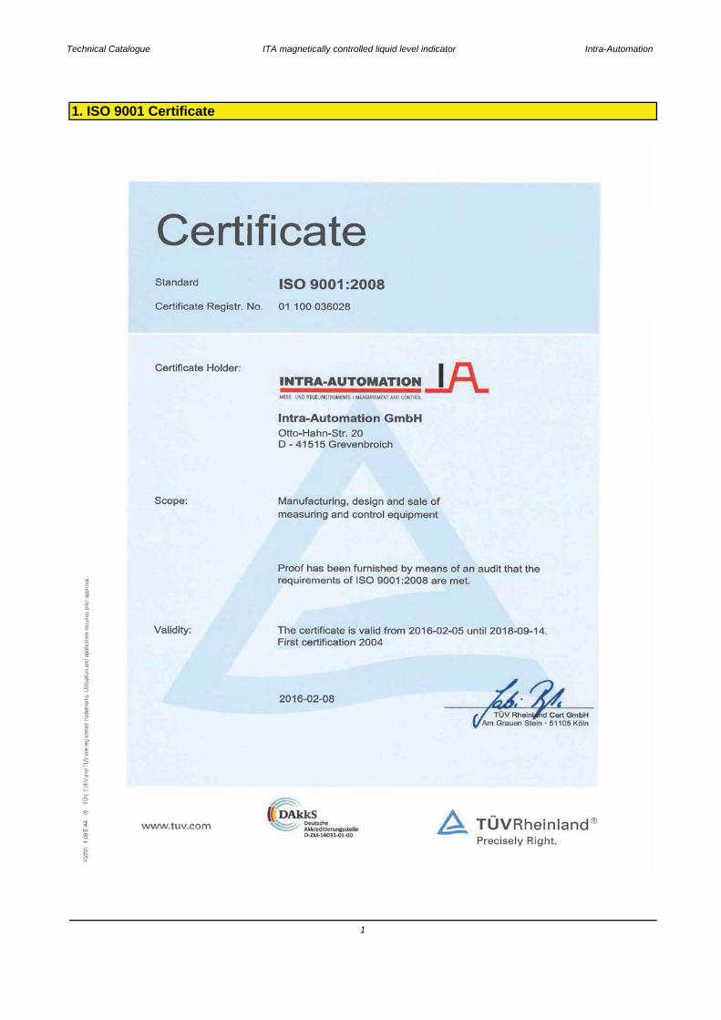
1. ISO 9001 Certificate
1
Technical Catalogue ITA magnetically controlled liquid level indicator Intra-Automation
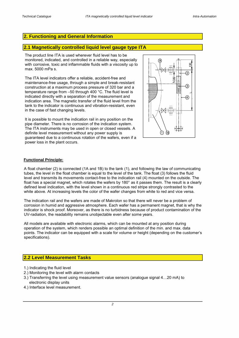
Functional Principle:
1.) Indicating the fluid level2.) Monitoring the level with alarm contacts3.) Transferring the level using measurement value sensors (analogue signal 4…20 mA) to electronic display units4.) Interface level measurement.
2. Functioning and General Information
2.1 Magnetically controlled liquid level gauge type ITA
2.2 Level Measurement Tasks
2
The product line ITA is used wherever fluid level has to be monitored, indicated, and controlled in a reliable way, especially with corrosive, toxic and inflammable fluids with a viscosity up to max. 5000 mPa s.
The ITA level indicators offer a reliable, accident-free and maintenance-free usage, through a simple and break-resistant construction at a maximum process pressure of 320 bar and a temperature range from –50 through 400 °C. The fluid level is indicated directly with a separation of the measurement and indication area. The magnetic transfer of the fluid level from the tank to the indicator is continuous and vibration-resistant, even in the case of fast changing levels.
It is possible to mount the indication rail in any position on the pipe diameter. There is no corrosion of the indication system. The ITA instruments may be used in open or closed vessels. A definite level measurement without any power supply is guaranteed due to a continuous rotation of the wafers, even if a power loss in the plant occurs.
A float chamber (2) is connected (1A and 1B) to the tank (1), and following the law of communicating tubes, the level in the float chamber is equal to the level of the tank. The float (3) follows the fluid level and transmits its movements contact-free to the indication rail (4) mounted on the outside. The float has a special magnet, which rotates the wafers by 180° as it passes them. The result is a clearly defined level indication, with the level shown in a continuous red stripe strongly contrasted to the white above. At increasing levels the color of the wafer changes from white to red and vice versa.
The indication rail and the wafers are made of Makrolon so that there will never be a problem of corrosion in humid and aggressive atmosphere. Each wafer has a permanent magnet, that is why the indicator is shock proof. Moreover, as there is no turbidness because of product contamination of the UV-radiation, the readability remains unobjectable even after some years.
All models are available with electronic alarms, which can be mounted at any position during operation of the system, which renders possible an optimal definition of the min. and max. data points. The indicator can be equipped with a scale for volume or height (depending on the customer’s specifications).
Technical Catalogue ITA magnetically controlled liquid level indicator Intra-Automation
2.3 Advantages
2.4 Switches / Alarm Contacts
2.5 Floats
3
No risk of glass breakage as a result of the separation of the measurement and indicator areas. The float principle means that changes of the density in the medium have very little influence on the indication accuracy.
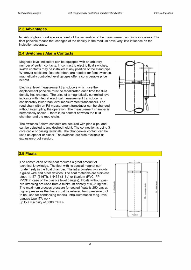
Magnetic level indicators can be equipped with an arbitrary number of switch contacts. In contrast to electric float switches, switch contacts may be installed at any position of the stand pipe. Wherever additional float chambers are needed for float switches, magnetically controlled level gauges offer a considerable price benefit.
Electrical level measurement transducers which use the displacement principle must be recalibrated each time the fluid density has changed. The price of a magnetically controlled level indicator with integral electrical measurement transducer is considerably lower than level measurement transducers. The reed chain with an R/I measurement transducer can be changed without interrupting the operation. The measurement chamber is hermetically sealed – there is no contact between the fluid chamber and the reed chain.
The switches / alarm contacts are secured with pipe clips, and can be adjusted to any desired height. The connection is using 3-core cable or casing terminals. The changeover contact can be used as opener or closer. The switches are also available as explosion-proof version.
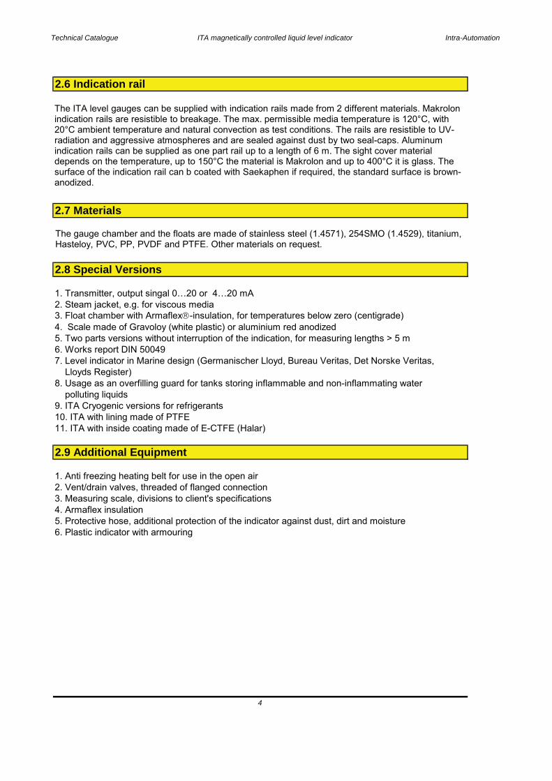
The construction of the float requires a great amount of technical knowledge. The float with its special magnet can rotate freely in the float chamber. The Intra construction avoids a guide wire and other devices. The float materials are stainless steel, 1.4571(316Ti), 1.4435 (316L) or titanium (PVC, PP, PVDF in case of the plastics level gauges). Floats without gas-pre-stressing are used from a minimum density of 0,35 kg/dm³. The maximum process pressure for sealed floats is 250 bar; at higher pressures the floats must be relieved from pressure (not to be used for condensing media). Intra-Automation mag. level gauges type ITA workup to a viscosity of 5000 mPa s.
Technical Catalogue ITA magnetically controlled liquid level indicator Intra-Automation
1. Transmitter, output singal 0…20 or 4…20 mA2. Steam jacket, e.g. for viscous media3. Float chamber with Armaflex -insulation, for temperatures below zero (centigrade)4. Scale made of Gravoloy (white plastic) or aluminium red anodized5. Two parts versions without interruption of the indication, for measuring lengths > 5 m6. Works report DIN 500497. Level indicator in Marine design (Germanischer Lloyd, Bureau Veritas, Det Norske Veritas, Lloyds Register)8. Usage as an overfilling guard for tanks storing inflammable and non-inflammating water polluting liquids9. ITA Cryogenic versions for refrigerants10. ITA with lining made of PTFE11. ITA with inside coating made of E-CTFE (Halar)
1. Anti freezing heating belt for use in the open air2. Vent/drain valves, threaded of flanged connection3. Measuring scale, divisions to client's specifications4. Armaflex insulation5. Protective hose, additional protection of the indicator against dust, dirt and moisture6. Plastic indicator with armouring
2.9 Additional Equipment
4
2.6 Indication rail
2.7 Materials
2.8 Special Versions
The ITA level gauges can be supplied with indication rails made from 2 different materials. Makrolon indication rails are resistible to breakage. The max. permissible media temperature is 120°C, with 20°C ambient temperature and natural convection as test conditions. The rails are resistible to UV-radiation and aggressive atmospheres and are sealed against dust by two seal-caps. Aluminum indication rails can be supplied as one part rail up to a length of 6 m. The sight cover material depends on the temperature, up to 150°C the material is Makrolon and up to 400°C it is glass. The surface of the indication rail can b coated with Saekaphen if required, the standard surface is brown-anodized.
The gauge chamber and the floats are made of stainless steel (1.4571), 254SMO (1.4529), titanium, Hasteloy, PVC, PP, PVDF and PTFE. Other materials on request.

Technical Catalogue ITA magnetically controlled liquid level indicator Intra-Automation
1. Material certificate EN 10204 2.12. Material certificate EN 10204 2.23. Material certificate EN 10204 3.1/3.2/3.34. Test according to NACE5. Pressure test certificate6. Pressure test according to "AD-Merkblatt" by the German TÜV7. Construction and pressure test as per TRD by the TÜV8. Dye penetration test DIN 541529. X-ray-test in accordance with DN 54111 part 110. PMI-check11. ATEX certification12. General approval of construction inspection in accordance with § 19 water resources law - WHG - and § 12 law about flammable liquids - VbF13. Water level controller component check as per VdTÜV/WR91-35214. Germanischer Lloyd15. Certificate of Passivation16. Weight certificate17. PED 97/23/EG
2.10 Inspection / Certificates
5

Technical Catalogue ITA magnetically controlled liquid level indicator Intra-Automation
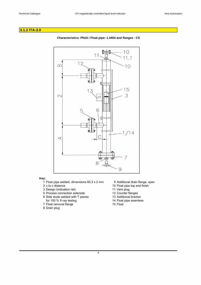
Key:1 Float pipe welded, dimensions 60,3 x 2 mm 9 Additional drain flange, open2 c to c distance 10 Float pipe top end finish3 Design (indication rail) 11 Vent plug5 Process connection side/side 12 Counter flanges6 Side studs welded with T pieces 13 Additional bracket
for 100 % X-ray testing 14 Float pipe seamless7 Float removal flange 15 Float8 Drain plug
3. Level Gauges in Details
3.1.1 ITA-3
Characteristics: PN16 / Float pipe and flange material: 1.4404
6

Technical Catalogue ITA magnetically controlled liquid level indicator Intra-Automation
Base equipment printed in bold letters!*for densities < 0,7374 kg/dm³ enlarge the scale A**only with vent- and/or drain flanges DN50 resp. 2"
Mounting position: vertical
Technical specifications magnetic level gauge type ITA-3
Principle: Communicating tubes with magnetic float
Pipe diameter: 60,3 x 2 mm welded,
Measuring range: max. 5000 mm (one-part)> 5000 mm 2- or multipart
necking connection or buttweld with T-pieces
60,3 x 2 mm seamless2" Sch10
Welding or threaded stud
Process connection: to specify:Flanges DN15…50 (1/2"…2" 150#),
Inconel 625 (2.4856); Inconel 825 (2.4858);Titan (3.7035) (other materials on request)
Drain/Vent connections: Plug R1/2" (for more please see order codes)
Pipe material: 1.4404; 1.4435; 1.4539; Hastelloy C4 (2.4610);
Float material: 1.4404Flange material: same as pipe material
Operation temperature: -50..+400 °C
Titan, Titan/E-CTFE-coated
Operation density: min. 0,3761 kg/dm³
Operation pressure: max. 16 bar
Bolts & Nuts: CSViscosity: max. 5000 mPa s
Gasket PTFE up to 100 °CKlingersil C4400 up to 175 °C
SS
Indication rail: Makrolon up to 120 °CAluminium up to 400 °C
Graphit spiral wound up to 400 °C**
Float types: Cylindical, sealed typeLength:
1.4301 up to 400 °C
-150 mm-210 mm
-270 mm-130 mm
-530 mm-630 mm
-330 mm-430 mm
7
-B = 130 mm- C = 40 mm
Standard dimensions: -A = 240 mm*
Technical Catalogue ITA magnetically controlled liquid level indicator Intra-Automation
Key:1 Float pipe welded, dimensions 60,3 x 2 mm 9 Additional drain flange, open2 c to c distance 10 Float pipe top end finish3 Design (indication rail) 11 Vent plug5 Process connection side/side 12 Counter flanges6 Side studs welded with T pieces 13 Additional bracket
for 100 % X-ray testing 14 Float pipe seamless7 Float removal flange 15 Float8 Drain plug
8
3.1.2 ITA-3.0
Characteristics: PN16 / Float pipe: 1.4404 and flanges : CS
Technical Catalogue ITA magnetically controlled liquid level indicator Intra-Automation
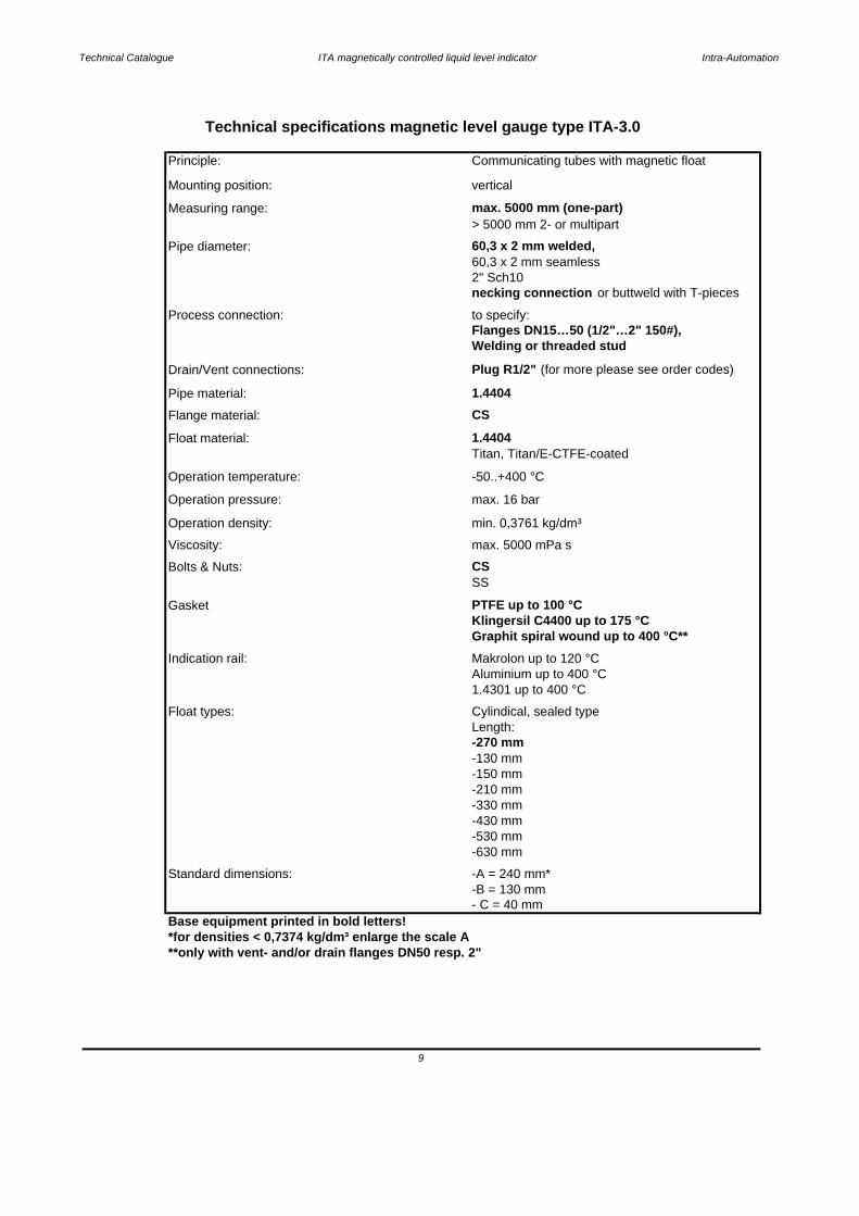
Base equipment printed in bold letters!*for densities < 0,7374 kg/dm³ enlarge the scale A**only with vent- and/or drain flanges DN50 resp. 2"
Technical specifications magnetic level gauge type ITA-3.0
Principle: Communicating tubes with magnetic float
Mounting position: vertical
Measuring range: max. 5000 mm (one-part)> 5000 mm 2- or multipart
Pipe diameter: 60,3 x 2 mm welded,60,3 x 2 mm seamless2" Sch10necking connection or buttweld with T-pieces
Process connection: to specify:Flanges DN15…50 (1/2"…2" 150#),Welding or threaded stud
Drain/Vent connections: Plug R1/2" (for more please see order codes)
Pipe material: 1.4404Flange material: CS
Float material: 1.4404Titan, Titan/E-CTFE-coated
Operation temperature: -50..+400 °C
Operation pressure: max. 16 bar
Operation density: min. 0,3761 kg/dm³
Bolts & Nuts: CSViscosity: max. 5000 mPa s
SS
Gasket PTFE up to 100 °CKlingersil C4400 up to 175 °CGraphit spiral wound up to 400 °C**
Indication rail: Makrolon up to 120 °CAluminium up to 400 °C1.4301 up to 400 °C
Float types: Cylindical, sealed typeLength: -270 mm-130 mm-150 mm-210 mm-330 mm-430 mm-530 mm-630 mm
Standard dimensions: -A = 240 mm*
9
-B = 130 mm- C = 40 mm

3.1.3 Pressure-Temperature Table ITA-3 (Float pipe)
10

Technical Catalogue ITA magnetically controlled liquid level indicator Intra-Automation
Description
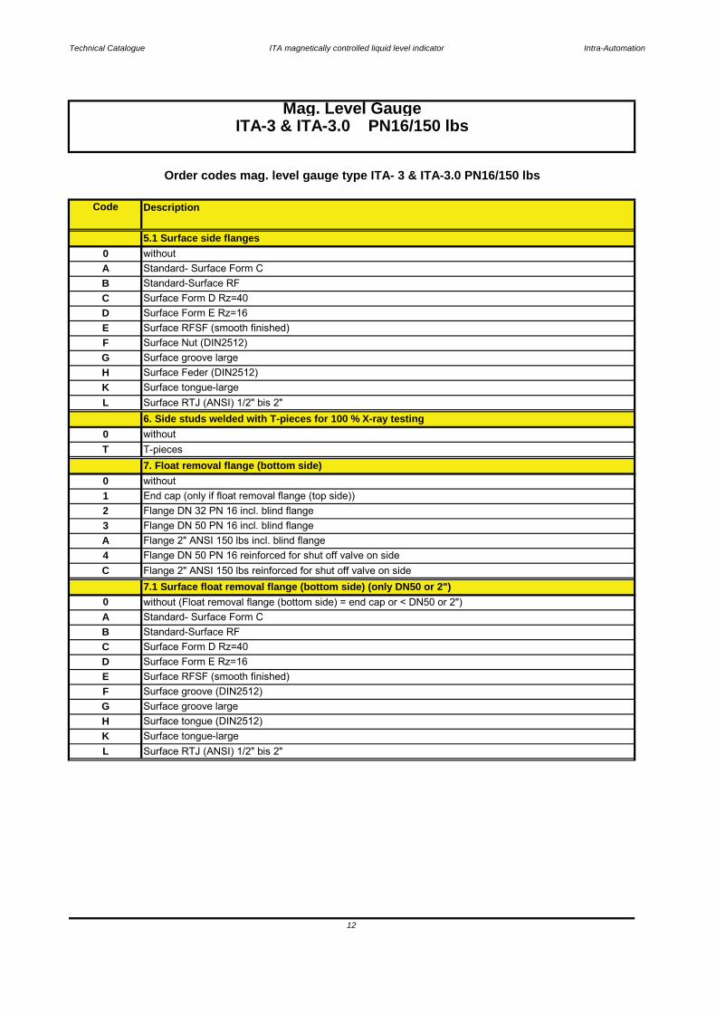
3.1.4 Order codes ITA-3 & ITA-3.0
3 Indication rail material: 1.4401 max. 400 °C, pro 100 mm2 Indication rail material: Aluminium max. 400 °C, pro 100 mm
A > 5000 mm - with flange connection; 2" ANSI 150 lbs, two or more parts design5. Process connection side/side
Code
Mag. Level GaugeITA-3 & ITA-3.0 PN16/150 lbs
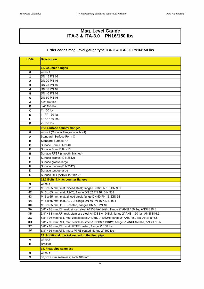
Order codes mag. level gauge type ITA- 3 & ITA-3.0 PN16/150 lbs
2. c to c distance
ITA-3 1. Float pipe weldedDimensions 60,3 x 2 mm
1 Indication rail material: Makrolon max. 120 °C; each 100 mm
c to c distance in mm
0 without indication rail each 100 mm
L3. Design
4. c to c distance < 5000 mm0 < 5000 mm - one part design
4 Flanges DN 32 PN 16
Y Welding connection (please specify)0 without
Z Threaded connection (please specify)1 Flanges DN 15 PN 16
3 Flanges DN 25 PN 162 Flanges DN 20 PN 16
6 Flanges DN 50 PN 16
D Flanges 1 1/4" ANSI 150 lbs
Flanges 1/2" ANSI 150 lbs B Flanges 3/4" ANSI 150 lbsC Flanges 1" ANSI 150 lbs
Flanges 2" ANSI 150 lbs
Flanges DN 40 PN 16
A
5
Flanges 300 lbs
H additional price for flanges 300 lbs0 without
E Flanges 1 1/2" ANSI 150 lbsF
11
1 > 5000 mm - with flange connection; DN 32 PN 16, two or more parts design2 > 5000 mm - with flange connection; DN 50 PN 16, two or more parts design
Technical Catalogue ITA magnetically controlled liquid level indicator Intra-Automation
Description
without
F Surface Nut (DIN2512)
5.1 Surface side flanges
A Standard- Surface Form C
Code
ESurface Form E Rz=16Surface Form D Rz=40
D
B Standard-Surface RFC
0 without6. Side studs welded with T-pieces for 100 % X-ray testing
G
T T-pieces
Surface Feder (DIN2512)K Surface tongue-largeL Surface RTJ (ANSI) 1/2" bis 2"
H
Order codes mag. level gauge type ITA- 3 & ITA-3.0 PN16/150 lbs
Surface groove large
0
Surface RFSF (smooth finished)
Mag. Level GaugeITA-3 & ITA-3.0 PN16/150 lbs
3 Flange DN 50 PN 16 incl. blind flange2
7. Float removal flange (bottom side)
1Flange DN 32 PN 16 incl. blind flange
0 withoutEnd cap (only if float removal flange (top side))
Flange DN 50 PN 16 reinforced for shut off valve on side4A
C Flange 2" ANSI 150 lbs reinforced for shut off valve on side7.1 Surface float removal flange (bottom side) (only DN50 or 2")
Flange 2" ANSI 150 lbs incl. blind flange
0
F Surface groove (DIN2512)
D Surface Form E Rz=16C Surface Form D Rz=40
without (Float removal flange (bottom side) = end cap or < DN50 or 2")
E Surface RFSF (smooth finished)
B Standard-Surface RFA Standard- Surface Form C
K Surface tongue-largeL Surface RTJ (ANSI) 1/2" bis 2"
G Surface groove largeH Surface tongue (DIN2512)
12
Technical Catalogue ITA magnetically controlled liquid level indicator Intra-Automation
Description
13
3X M16 x 65 mm, PTFE-coated, flanges DN 50 PN 16
3C 5/8" x 95 mm;RTJ, mat. zinced steel A193B7/A1942H; flange 2" ANSI 150 lbs, ANSI B16.5
3T 5/8" x 83 mm;RF, mat.: PTFE coated, flange 2" 150 lbs
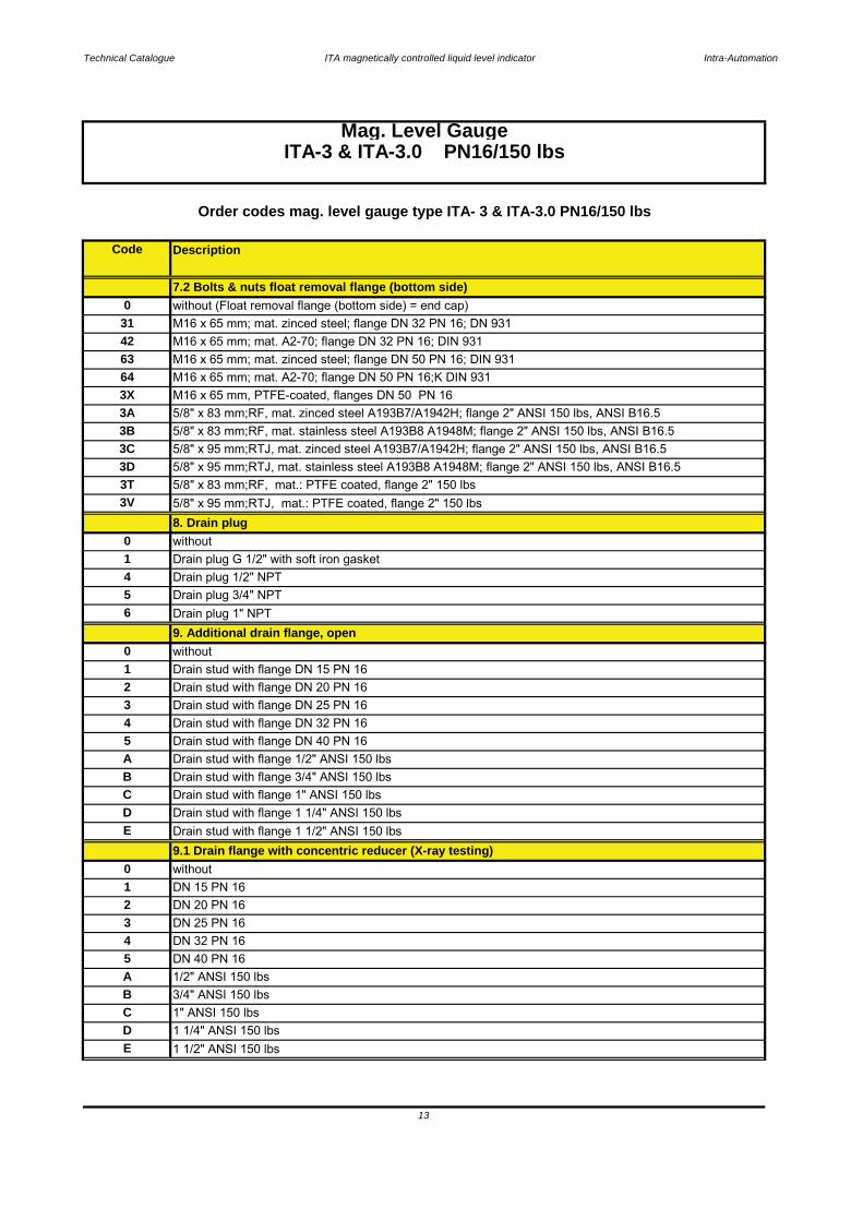
8. Drain plug3V 5/8" x 95 mm;RTJ, mat.: PTFE coated, flange 2" 150 lbs
3D 5/8" x 95 mm;RTJ, mat. stainless steel A193B8 A1948M; flange 2" ANSI 150 lbs, ANSI B16.5
31 M16 x 65 mm; mat. zinced steel; flange DN 32 PN 16; DN 93142 M16 x 65 mm; mat. A2-70; flange DN 32 PN 16; DIN 931
7.2 Bolts & nuts float removal flange (bottom side)0 without (Float removal flange (bottom side) = end cap)
3A 5/8" x 83 mm;RF, mat. zinced steel A193B7/A1942H; flange 2" ANSI 150 lbs, ANSI B16.53B 5/8" x 83 mm;RF, mat. stainless steel A193B8 A1948M; flange 2" ANSI 150 lbs, ANSI B16.5
63 M16 x 65 mm; mat. zinced steel; flange DN 50 PN 16; DIN 93164 M16 x 65 mm; mat. A2-70; flange DN 50 PN 16;K DIN 931
9. Additional drain flange, open
4 Drain plug 1/2" NPT5 Drain plug 3/4" NPT
Mag. Level GaugeITA-3 & ITA-3.0 PN16/150 lbs
6 Drain plug 1" NPT
0 without1 Drain plug G 1/2" with soft iron gasket
0 without
2 Drain stud with flange DN 20 PN 161 Drain stud with flange DN 15 PN 16
3 Drain stud with flange DN 25 PN 16
1" ANSI 150 lbs
E
1
D
5 Drain stud with flange DN 40 PN 164
A
Drain stud with flange 1" ANSI 150 lbs
2
Drain stud with flange 1/2" ANSI 150 lbsB
DN 15 PN 16without
Drain stud with flange 3/4" ANSI 150 lbs
0
E
DN 25 PN 16
C
9.1 Drain flange with concentric reducer (X-ray testing)
34
Order codes mag. level gauge type ITA- 3 & ITA-3.0 PN16/150 lbs
Code
A 1/2" ANSI 150 lbs
Drain stud with flange DN 32 PN 16
Drain stud with flange 1 1/4" ANSI 150 lbs
DN 20 PN 16
Drain stud with flange 1 1/2" ANSI 150 lbs
DN 32 PN 16
C
5 DN 40 PN 16
3/4" ANSI 150 lbs
1 1/4" ANSI 150 lbs1 1/2" ANSI 150 lbs
D
B

Technical Catalogue ITA magnetically controlled liquid level indicator Intra-Automation
Bezeichnung
14
Mag. Level GaugeITA-3 & ITA-3.0 PN16/150 lbs
3C 5/8" x 95 mm;RTJ, mat. zinced steel A193B7/A1942H; flange 2" ANSI 150 lbs, ANSI B16.53D
5/8" x 83 mm;RF, mat. stainless steel A193B8 A1948M; flange 2" ANSI 150 lbs, ANSI B16.5
64
5/8" x 95 mm;RTJ, mat. stainless steel A193B8 A1948M; flange 2" ANSI 150 lbs, ANSI B16.5
Code
Order codes mag. level gauge type ITA- 3 & ITA-3.0 PN16/150 lbs
3B
3T 5/8" x 83 mm;RF, mat.: PTFE coated, flange 2" 150 lbs3V 5/8" x 95 mm;RTJ, mat.: PTFE coated, flange 2" 150 lbs
4 Flange with blind flange 2" ANSI 150 lbs
M16 x 65 mm; mat. A2-70; flange DN 32 PN 16; DIN 93163 M16 x 65 mm; mat. zinced steel; flange DN 50 PN 16; DIN 93142
10.1 Surface float pipe top end finish flange (only DN50 or 2")0 without (Float pipe top end finish = End cap or < DN50 or 2")
9.2 Surface open drain flange0 without (additional drain flange = without)
B Surface RFA Suface Form C
E Surface RFSF (smooth finished)F Surface groove (DIN2512)
C Surface Form D Rz=40D Surface Form E Rz=16
K Surface tongue-large (ANSI B16.5)L Surface RTJ (ANSI B16.5) 1/2" to 2"
G Surface groove large (ANSI B16.5)H Surface tongue (DIN2512)
10. Float pipe top end finish
1 End cap0 without
2 Flange with blind flange DN 32 PN 163 Flange with blind flange DN 50 PN 165 Flange with blind flange DN 50 PN 16, reinforced for shut off valve on side
4 Flange with blind flange 2" ANSI 150 lbs reinforced for shut off valve on side
C Surface Form D Rz=40D Surface Form E Rz=16
A Standard- Surface Form CB Standard-Surface RF
G Surface groove largeH Surface tongue (DIN2512)
E Surface RFSF (smooth finished)F Surface groove (DIN2512)
K Surface tongue-large
10.2 Bolts & nuts float pipe top end finish flange (only DN50 or 2")L Surface RTJ (ANSI) 1/2" bis 2"
M16 x 65 mm, PTFE-coated, flanges DN 50 PN 163A 5/8" x 83 mm;RF, mat. zinced steel A193B7/A1942H; flange 2" ANSI 150 lbs, ANSI B16.5
0 without (Float removal flange (bottom side) = end cap)31 M16 x 65 mm; mat. zinced steel; flange DN 32 PN 16; DN 931
M16 x 65 mm; mat. A2-70; flange DN 50 PN 16;K DIN 9313X
Technical Catalogue ITA magnetically controlled liquid level indicator Intra-Automation
Description
15
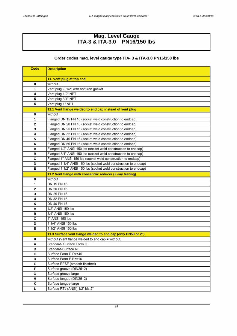
Flanged DN 15 PN 16 (socket weld construction to endcap)
Mag. Level GaugeITA-3 & ITA-3.0 PN16/150 lbs
2 Flanged DN 20 PN 16 (socket weld construction to endcap)
11.1 Vent flange welded to end cap instead of vent plug
1
4
C
0 without
11. Vent plug at top end
1 Vent plug G 1/2" with soft iron gasket0 without
3 Flanged DN 25 PN 16 (socket weld construction to endcap)
6
4 Vent plug 1/2" NPT5 Vent plug 3/4" NPT
Vent plug 1" NPT
B Flanged 3/4" ANSI 150 lbs (socket weld construction to endcap)
Flanged DN 32 PN 16 (socket weld construction to endcap)5 Flanged DN 40 PN 16 (socket weld construction to endcap)
Flanged 1" ANSI 150 lbs (socket weld construction to endcap)
6 Flanged DN 50 PN 16 (socket weld construction to endcap)A Flanged 1/2" ANSI 150 lbs (socket weld construction to endcap)
11.2 Vent flange with concentric reducer (X-ray testing)0 without
D Flanged 1 1/4" ANSI 150 lbs (socket weld construction to endcap)E Flanged 1 1/2" ANSI 150 lbs (socket weld construction to endcap)
3 DN 25 PN 164 DN 32 PN 16
1 DN 15 PN 162 DN 20 PN 16
B 3/4" ANSI 150 lbsC 1" ANSI 150 lbs
5 DN 40 PN 16A 1/2" ANSI 150 lbs
11.3 Surface vent flange welded to end cap (only DN50 or 2")0 without (Vent flange welded to end cap = without)
D 1 1/4" ANSI 150 lbsE 1 1/2" ANSI 150 lbs
E Surface RFSF (smooth finished)
A Standard- Surface Form CB Standard-Surface RFC Surface Form D Rz=40D Surface Form E Rz=16
F Surface groove (DIN2512)
K Surface tongue-largeHG Surface groove large
Surface tongue (DIN2512)
L Surface RTJ (ANSI) 1/2" bis 2"
Order codes mag. level gauge type ITA- 3 & ITA-3.0 PN16/150 lbs
Code
Technical Catalogue ITA magnetically controlled liquid level indicator Intra-Automation
Description
16
3V 5/8" x 95 mm;RTJ, mat.: PTFE coated, flange 2" 150 lbs
3C 5/8" x 95 mm;RTJ, mat. zinced steel A193B7/A1942H; flange 2" ANSI 150 lbs, ANSI B16.53D 5/8" x 95 mm;RTJ, mat. stainless steel A193B8 A1948M; flange 2" ANSI 150 lbs, ANSI B16.53T 5/8" x 83 mm;RF, mat.: PTFE coated, flange 2" 150 lbs
3B 5/8" x 83 mm;RF, mat. stainless steel A193B8 A1948M; flange 2" ANSI 150 lbs, ANSI B16.53A 5/8" x 83 mm;RF, mat. zinced steel A193B7/A1942H; flange 2" ANSI 150 lbs, ANSI B16.5
0 without
42 M16 x 65 mm; mat. A2-70; flange DN 32 PN 16; DIN 93131 M16 x 65 mm; mat. zinced steel; flange DN 32 PN 16; DN 931
12. Counter flanges
2 DN 20 PN 161 DN 15 PN 160 without
DN 40 PN 16
3 DN 25 PN 164 DN 32 PN 16
B 3/4" 150 lbs
56 DN 50 PN 16A 1/2" 150 lbs
1 1/2" 150 lbsF 2" 150 lbs
C 1" 150 lbsD 1 1/4" 150 lbs
12.1 Surface counter flanges
Mag. Level GaugeITA-3 & ITA-3.0 PN16/150 lbs
Order codes mag. level gauge type ITA- 3 & ITA-3.0 PN16/150 lbs
Code
E
B Standard-Surface RFC Surface Form D Rz=40
0 without (Counter flanges = without)A Standard- Surface Form C
F Surface groove (DIN2512)G Surface groove large
D Surface Form E Rz=16E Surface RFSF (smooth finished)
L Surface RTJ (ANSI) 1/2" bis 2"12.2 Bolts & Nuts counter flanges
H Surface tongue (DIN2512)K Surface tongue-large
3X M16 x 65 mm, PTFE-coated, flanges DN 50 PN 16
63 M16 x 65 mm; mat. zinced steel; flange DN 50 PN 16; DIN 93164 M16 x 65 mm; mat. A2-70; flange DN 50 PN 16;K DIN 931
S 60,3 x 2 mm seamless; each 100 mm
14. Float pipe seamless0 without
H Bracket
13. Additional bracket welded to the float pipe0 without
Technical Catalogue ITA magnetically controlled liquid level indicator Intra-Automation
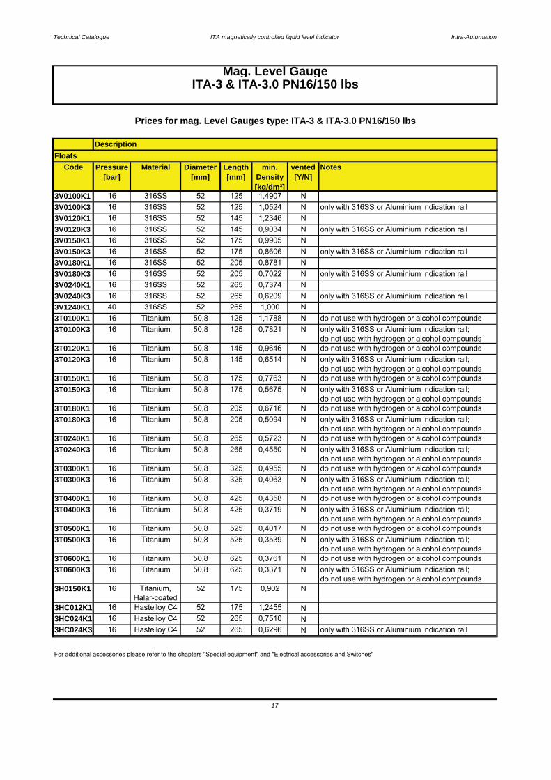
Code Pressure[bar]
Material Diameter[mm]
Length[mm]
min. Density[kg/dm³]
vented[Y/N]
Notes
3V0100K1 16 316SS 52 125 1,4907 N3V0100K3 16 316SS 52 125 1,0524 N only with 316SS or Aluminium indication rail3V0120K1 16 316SS 52 145 1,2346 N3V0120K3 16 316SS 52 145 0,9034 N only with 316SS or Aluminium indication rail3V0150K1 16 316SS 52 175 0,9905 N3V0150K3 16 316SS 52 175 0,8606 N only with 316SS or Aluminium indication rail3V0180K1 16 316SS 52 205 0,8781 N3V0180K3 16 316SS 52 205 0,7022 N only with 316SS or Aluminium indication rail3V0240K1 16 316SS 52 265 0,7374 N3V0240K3 16 316SS 52 265 0,6209 N only with 316SS or Aluminium indication rail3V1240K1 40 316SS 52 265 1,000 N3T0100K1 16 Titanium 50,8 125 1,1788 N do not use with hydrogen or alcohol compounds3T0100K3 16 Titanium 50,8 125 0,7821 N only with 316SS or Aluminium indication rail;
do not use with hydrogen or alcohol compounds3T0120K1 16 Titanium 50,8 145 0,9646 N do not use with hydrogen or alcohol compounds3T0120K3 16 Titanium 50,8 145 0,6514 N only with 316SS or Aluminium indication rail;
do not use with hydrogen or alcohol compounds3T0150K1 16 Titanium 50,8 175 0,7763 N do not use with hydrogen or alcohol compounds3T0150K3 16 Titanium 50,8 175 0,5675 N only with 316SS or Aluminium indication rail;
do not use with hydrogen or alcohol compounds3T0180K1 16 Titanium 50,8 205 0,6716 N do not use with hydrogen or alcohol compounds3T0180K3 16 Titanium 50,8 205 0,5094 N only with 316SS or Aluminium indication rail;
do not use with hydrogen or alcohol compounds3T0240K1 16 Titanium 50,8 265 0,5723 N do not use with hydrogen or alcohol compounds3T0240K3 16 Titanium 50,8 265 0,4550 N only with 316SS or Aluminium indication rail;
do not use with hydrogen or alcohol compounds3T0300K1 16 Titanium 50,8 325 0,4955 N do not use with hydrogen or alcohol compounds3T0300K3 16 Titanium 50,8 325 0,4063 N only with 316SS or Aluminium indication rail;
do not use with hydrogen or alcohol compounds3T0400K1 16 Titanium 50,8 425 0,4358 N do not use with hydrogen or alcohol compounds3T0400K3 16 Titanium 50,8 425 0,3719 N only with 316SS or Aluminium indication rail;
do not use with hydrogen or alcohol compounds3T0500K1 16 Titanium 50,8 525 0,4017 N do not use with hydrogen or alcohol compounds3T0500K3 16 Titanium 50,8 525 0,3539 N only with 316SS or Aluminium indication rail;
do not use with hydrogen or alcohol compounds3T0600K1 16 Titanium 50,8 625 0,3761 N do not use with hydrogen or alcohol compounds3T0600K3 16 Titanium 50,8 625 0,3371 N only with 316SS or Aluminium indication rail;
do not use with hydrogen or alcohol compounds3H0150K1 16 Titanium,
Halar-coated52 175 0,902 N
3HC012K1 16 Hastelloy C4 52 175 1,2455 N3HC024K1 16 Hastelloy C4 52 265 0,7510 N3HC024K3 16 Hastelloy C4 52 265 0,6296 N only with 316SS or Aluminium indication rail
17
Mag. Level GaugeITA-3 & ITA-3.0 PN16/150 lbs
For additional accessories please refer to the chapters "Special equipment" and "Electrical accessories and Switches"
Prices for mag. Level Gauges type: ITA-3 & ITA-3.0 PN16/150 lbs
DescriptionFloats
Technical Catalogue ITA magnetically controlled liquid level indicator Intra-Automation
18
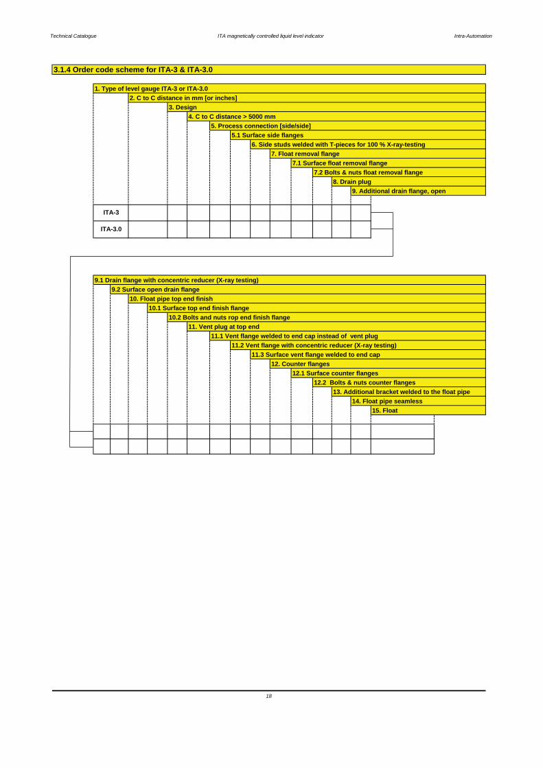
15. Float
10. Float pipe top end finish10.1 Surface top end finish flange
9.2 Surface open drain flange
3.1.4 Order code scheme for ITA-3 & ITA-3.0
14. Float pipe seamless
12. Counter flanges12.1 Surface counter flanges
12.2 Bolts & nuts counter flanges13. Additional bracket welded to the float pipe
9.1 Drain flange with concentric reducer (X-ray testing)
ITA-3
ITA-3.0
8. Drain plug9. Additional drain flange, open
11.3 Surface vent flange welded to end cap
10.2 Bolts and nuts rop end finish flange11. Vent plug at top end
11.1 Vent flange welded to end cap instead of vent plug11.2 Vent flange with concentric reducer (X-ray testing)
5. Process connection [side/side]5.1 Surface side flanges
6. Side studs welded with T-pieces for 100 % X-ray-testing7. Float removal flange
7.1 Surface float removal flange7.2 Bolts & nuts float removal flange
1. Type of level gauge ITA-3 or ITA-3.02. C to C distance in mm [or inches]
3. Design4. C to C distance > 5000 mm
Technical Catalogue ITA magnetically controlled liquid level indicator Intra-Automation
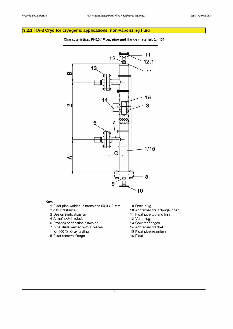
Key:1 Float pipe welded, dimensions 60,3 x 2 mm 9 Drain plug2 c to c distance 10 Additional drain flange, open3 Design (indication rail) 11 Float pipe top end finish4 Armaflex insulation 12 Vent plug6 Process connection side/side 13 Counter flanges7 Side studs welded with T pieces 14 Additional bracket
for 100 % X-ray testing 15 Float pipe seamless8 Float removal flange 16 Float
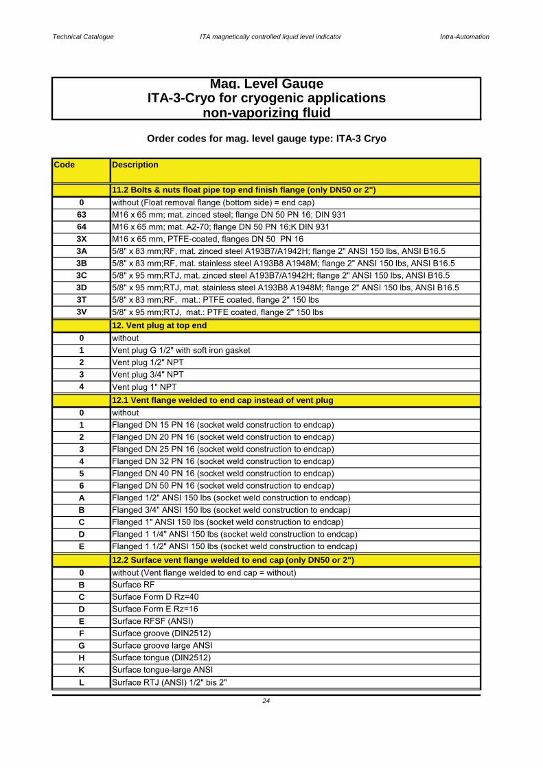
3.2.1 ITA-3 Cryo for cryogenic applications, non-vaporizing fluid
Characteristics: PN16 / Float pipe and flange material: 1.4404
19
Technical Catalogue ITA magnetically controlled liquid level indicator Intra-Automation
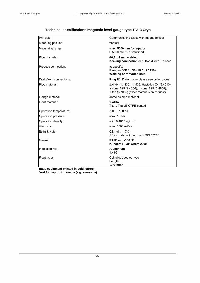
Base equipment printed in bold letters!*not for vaporizing media (e.g. ammonia)
20
Aluminium
-270 mm*
Float types: Cylindical, sealed typeLength:
1.4301
Klingersil TOP Chem 2000Indication rail:
SS or material in acc. with DIN 17280Gasket PTFE min -150 °C
Bolts & Nuts: CS (min. -10°C)
Viscosity: max. 5000 mPa s
Operation density: min. 0,4017 kg/dm³
Operation temperature: -200..+100 °C
Operation pressure: max. 16 bar
Float material: 1.4404Titan, Titan/E-CTFE-coated
Flange material: same as pipe material
Pipe material: 1.4404; 1.4435; 1.4539; Hastelloy C4 (2.4610); Inconel 625 (2.4856); Inconel 825 (2.4858);Titan (3.7035) (other materials on request)
Drain/Vent connections: Plug R1/2" (for more please see order codes)
Process connection: to specify:Flanges DN15…50 (1/2"…2" 150#),Welding or threaded stud
Pipe diameter: 60,3 x 2 mm welded,necking connection or buttweld with T-pieces
Measuring range: max. 5000 mm (one-part)> 5000 mm 2- or multipart
Mounting position: vertical
Technical specifications magnetic level gauge type ITA-3 Cryo
Principle: Communicating tubes with magnetic float
Technical Catalogue ITA magnetically controlled liquid level indicator Intra-Automation
Code Description
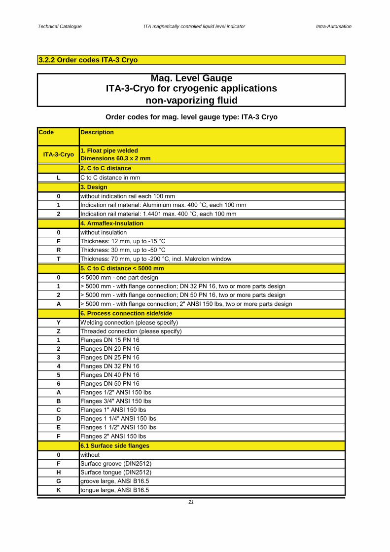
3.2.2 Order codes ITA-3 Cryo
21
0 withoutF Surface groove (DIN2512)H Surface tongue (DIN2512)
D Flanges 1 1/4" ANSI 150 lbs
6.1 Surface side flanges
E Flanges 1 1/2" ANSI 150 lbsF Flanges 2" ANSI 150 lbs
> 5000 mm - with flange connection; DN 32 PN 16, two or more parts design
5 Flanges DN 40 PN 16
2 Flanges DN 20 PN 163 Flanges DN 25 PN 16
Z
2 > 5000 mm - with flange connection; DN 50 PN 16, two or more parts design
T Thickness: 70 mm, up to -200 °C, incl. Makrolon window5. C to C distance < 5000 mm
Threaded connection (please specify)
0 < 5000 mm - one part design
Y Welding connection (please specify)6. Process connection side/side
1
0 without indication rail each 100 mm
Thickness: 30 mm, up to -50 °CF Thickness: 12 mm, up to -15 °C0 without insulation
4. Armaflex-Insulation
R
ITA-3-Cryo 1. Float pipe welded Dimensions 60,3 x 2 mm2. C to C distance
Order codes for mag. level gauge type: ITA-3 Cryo
non-vaporizing fluid
Mag. Level GaugeITA-3-Cryo for cryogenic applications
4
A Flanges 1/2" ANSI 150 lbs
L C to C distance in mm3. Design
2 Indication rail material: 1.4401 max. 400 °C, each 100 mm1 Indication rail material: Aluminium max. 400 °C, each 100 mm
Flanges DN 50 PN 16
A > 5000 mm - with flange connection; 2" ANSI 150 lbs, two or more parts design
1
K tongue large, ANSI B16.5
Flanges DN 15 PN 16
G groove large, ANSI B16.5
Flanges DN 32 PN 16
B Flanges 3/4" ANSI 150 lbsC Flanges 1" ANSI 150 lbs
6
Technical Catalogue ITA magnetically controlled liquid level indicator Intra-Automation
Code Description
22
ITA-3-Cryo for cryogenic applicationsnon-vaporizing fluid
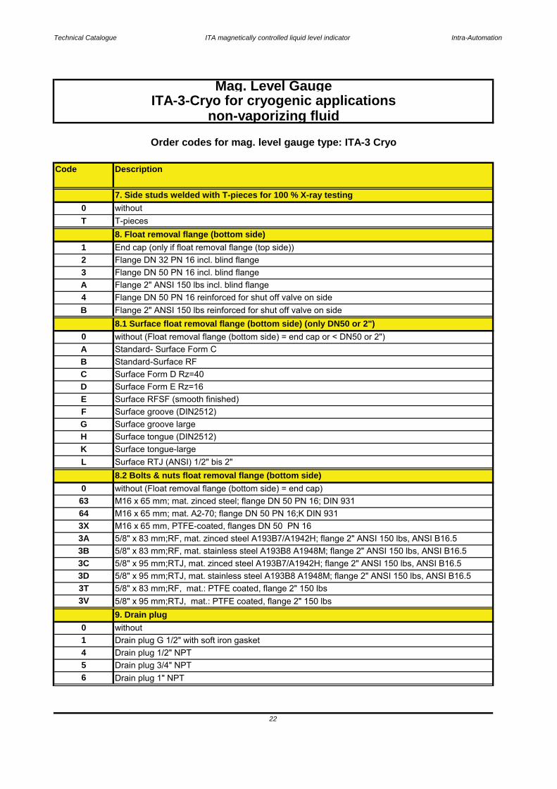
5 Drain plug 3/4" NPT6 Drain plug 1" NPT
63 M16 x 65 mm; mat. zinced steel; flange DN 50 PN 16; DIN 931
M16 x 65 mm, PTFE-coated, flanges DN 50 PN 163A
Order codes for mag. level gauge type: ITA-3 Cryo
4 Drain plug 1/2" NPT1 Drain plug G 1/2" with soft iron gasket0 without
9. Drain plug
8.2 Bolts & nuts float removal flange (bottom side)without (Float removal flange (bottom side) = end cap)0
64 M16 x 65 mm; mat. A2-70; flange DN 50 PN 16;K DIN 931
5/8" x 83 mm;RF, mat. zinced steel A193B7/A1942H; flange 2" ANSI 150 lbs, ANSI B16.53B 5/8" x 83 mm;RF, mat. stainless steel A193B8 A1948M; flange 2" ANSI 150 lbs, ANSI B16.5
HSurface tongue-large
L Surface RTJ (ANSI) 1/2" bis 2"
Surface tongue (DIN2512)K
D Surface Form E Rz=16E Surface RFSF (smooth finished)
G Surface groove largeF Surface groove (DIN2512)
B Standard-Surface RFA Standard- Surface Form C
8.1 Surface float removal flange (bottom side) (only DN50 or 2")
C Surface Form D Rz=40
Flange DN 32 PN 16 incl. blind flange3
Flange DN 50 PN 16 reinforced for shut off valve on side
0 without (Float removal flange (bottom side) = end cap or < DN50 or 2")
B Flange 2" ANSI 150 lbs reinforced for shut off valve on side
T T-pieces8. Float removal flange (bottom side)
4
1 End cap (only if float removal flange (top side))
Flange DN 50 PN 16 incl. blind flangeA Flange 2" ANSI 150 lbs incl. blind flange
2
7. Side studs welded with T-pieces for 100 % X-ray testing
3X
0 without
Mag. Level Gauge
3C 5/8" x 95 mm;RTJ, mat. zinced steel A193B7/A1942H; flange 2" ANSI 150 lbs, ANSI B16.5
3V 5/8" x 95 mm;RTJ, mat.: PTFE coated, flange 2" 150 lbs
3D 5/8" x 95 mm;RTJ, mat. stainless steel A193B8 A1948M; flange 2" ANSI 150 lbs, ANSI B16.53T 5/8" x 83 mm;RF, mat.: PTFE coated, flange 2" 150 lbs
Technical Catalogue ITA magnetically controlled liquid level indicator Intra-Automation
Code Description
23
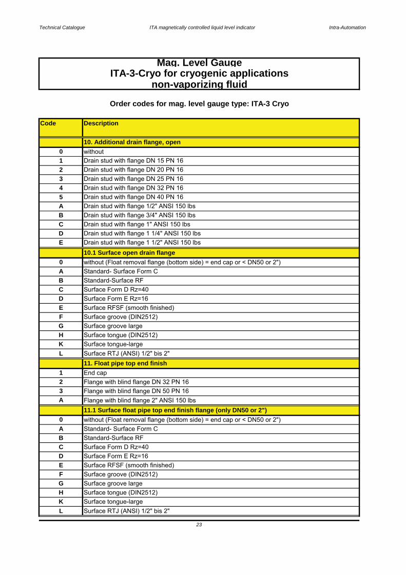
H Surface tongue (DIN2512)K Surface tongue-large
Mag. Level GaugeITA-3-Cryo for cryogenic applications
Surface RTJ (ANSI) 1/2" bis 2"L
G Surface groove large
11.1 Surface float pipe top end finish flange (only DN50 or 2")
Surface groove (DIN2512)
Flange with blind flange 2" ANSI 150 lbs
D Surface Form E Rz=16C
F
Surface Form D Rz=40
A
0
1
A Standard- Surface Form C
E Surface RFSF (smooth finished)
B Standard-Surface RF
H
without (Float removal flange (bottom side) = end cap or < DN50 or 2")
K
3 Flange with blind flange DN 50 PN 16
11. Float pipe top end finishL Surface RTJ (ANSI) 1/2" bis 2"
2 Flange with blind flange DN 32 PN 16
Surface Form E Rz=16
End cap
Standard-Surface RF
EFG
Surface tongue-large
Surface groove large
Surface RFSF (smooth finished)Surface groove (DIN2512)
Surface Form D Rz=40C
10.1 Surface open drain flange0 without (Float removal flange (bottom side) = end cap or < DN50 or 2")
Surface tongue (DIN2512)
D
A Standard- Surface Form CB
B Drain stud with flange 3/4" ANSI 150 lbsC Drain stud with flange 1" ANSI 150 lbs
E Drain stud with flange 1 1/2" ANSI 150 lbsD Drain stud with flange 1 1/4" ANSI 150 lbs
4 Drain stud with flange DN 32 PN 165 Drain stud with flange DN 40 PN 16A Drain stud with flange 1/2" ANSI 150 lbs
3 Drain stud with flange DN 25 PN 162 Drain stud with flange DN 20 PN 16
Order codes for mag. level gauge type: ITA-3 Cryo
non-vaporizing fluid
1 Drain stud with flange DN 15 PN 160 without
10. Additional drain flange, open
Technical Catalogue ITA magnetically controlled liquid level indicator Intra-Automation
Code Description
G Surface groove large ANSI
ITA-3-Cryo for cryogenic applications
24
Mag. Level Gauge
non-vaporizing fluid
Surface tongue-large ANSIH Surface tongue (DIN2512)KL Surface RTJ (ANSI) 1/2" bis 2"
F Surface groove (DIN2512)
C Surface Form D Rz=40D Surface Form E Rz=16E
Flanged DN 50 PN 16 (socket weld construction to endcap)
Flanged 1 1/4" ANSI 150 lbs (socket weld construction to endcap)
A
Surface RFSF (ANSI)
E Flanged 1 1/2" ANSI 150 lbs (socket weld construction to endcap)
B Flanged 3/4" ANSI 150 lbs (socket weld construction to endcap)C
Vent plug 1" NPT
Flanged 1/2" ANSI 150 lbs (socket weld construction to endcap)
Flanged 1" ANSI 150 lbs (socket weld construction to endcap)
B Surface RF0 without (Vent flange welded to end cap = without)
D
6
12.2 Surface vent flange welded to end cap (only DN50 or 2")
4 Flanged DN 32 PN 16 (socket weld construction to endcap)5 Flanged DN 40 PN 16 (socket weld construction to endcap)
Flanged DN 20 PN 16 (socket weld construction to endcap)23 Flanged DN 25 PN 16 (socket weld construction to endcap)
2 Vent plug 1/2" NPT
12.1 Vent flange welded to end cap instead of vent plug
1 Flanged DN 15 PN 16 (socket weld construction to endcap)0 without
3 Vent plug 3/4" NPT4
11.2 Bolts & nuts float pipe top end finish flange (only DN50 or 2")
3C 5/8" x 95 mm;RTJ, mat. zinced steel A193B7/A1942H; flange 2" ANSI 150 lbs, ANSI B16.5
3X M16 x 65 mm, PTFE-coated, flanges DN 50 PN 163A
0 without (Float removal flange (bottom side) = end cap)
64 M16 x 65 mm; mat. A2-70; flange DN 50 PN 16;K DIN 931
Order codes for mag. level gauge type: ITA-3 Cryo
5/8" x 83 mm;RF, mat. zinced steel A193B7/A1942H; flange 2" ANSI 150 lbs, ANSI B16.5
3V 5/8" x 95 mm;RTJ, mat.: PTFE coated, flange 2" 150 lbs
63 M16 x 65 mm; mat. zinced steel; flange DN 50 PN 16; DIN 931
3D 5/8" x 95 mm;RTJ, mat. stainless steel A193B8 A1948M; flange 2" ANSI 150 lbs, ANSI B16.53T 5/8" x 83 mm;RF, mat.: PTFE coated, flange 2" 150 lbs
3B 5/8" x 83 mm;RF, mat. stainless steel A193B8 A1948M; flange 2" ANSI 150 lbs, ANSI B16.5
0 without12. Vent plug at top end
1 Vent plug G 1/2" with soft iron gasket

Technical Catalogue ITA magnetically controlled liquid level indicator Intra-Automation
Code Description
25
A 1/2" 150 lbs
0 without15. Float pipe seamless
0 without (Float removal flange (bottom side) = end cap)13.2 Bolts & Nuts counter flanges
S 60,3 x 2 mm seamless; each 100 mm
14. Additional bracket welded to the float pipe0 withoutH Bracket
F Surface groove (DIN2512)0 without (Counter flanges = without)
H Surface tongue (DIN2512)
ITA-3-Cryo for cryogenic applicationsnon-vaporizing fluid
Order codes for mag. level gauge type: ITA-3 Cryo
13.1 Surface counter flanges
E 1 1/2" 150 lbsF 2" 150 lbs
D 1 1/4" 150 lbsC 1" 150 lbs
6 DN 50 PN 16
B 3/4" 150 lbs
5
1 DN 15 PN 162 DN 20 PN 163 DN 25 PN 164 DN 32 PN 16
DN 40 PN 16
0 without13. Counter flanges
Mag. Level Gauge
63 M16 x 65 mm; mat. zinced steel; flange DN 50 PN 16; DIN 93164 M16 x 65 mm; mat. A2-70; flange DN 50 PN 16;K DIN 931
3B 5/8" x 83 mm;RF, mat. stainless steel A193B8 A1948M; flange 2" ANSI 150 lbs, ANSI B16.53C 5/8" x 95 mm;RTJ, mat. zinced steel A193B7/A1942H; flange 2" ANSI 150 lbs, ANSI B16.5
3X M16 x 65 mm, PTFE-coated, flanges DN 50 PN 163A 5/8" x 83 mm;RF, mat. zinced steel A193B7/A1942H; flange 2" ANSI 150 lbs, ANSI B16.5
3V 5/8" x 95 mm;RTJ, mat.: PTFE coated, flange 2" 150 lbs
3D 5/8" x 95 mm;RTJ, mat. stainless steel A193B8 A1948M; flange 2" ANSI 150 lbs, ANSI B16.53T 5/8" x 83 mm;RF, mat.: PTFE coated, flange 2" 150 lbs

Technical Catalogue ITA magnetically controlled liquid level indicator Intra-Automation
Code Description
Pressure[bar] Material
16 Titanium
16 Titanium
16 Titanium
Mag. Level GaugeITA-3-Cryo for cryogenic applications
26
non-vaporizing fluid
0,5723 N do not use for hydrogene or alcohol compoundsdo not use for hydrogene or alcohol compounds
N0,5038 only with 316SS or Aluminium inication rail, do not use for hydrogene or alcohol compounds
0,5509 N
3C0240K1
3C0500K1
3C0500K3
45
50,8
45
Floats
Diameter[mm]
min. Density[kg/dm³]
vented[Y/N] notes
Order codes for mag. level gauge type: ITA-3 Cryo
Technical Catalogue ITA magnetically controlled liquid level indicator Intra-Automation
13. Counter flanges13.1 Surface counter flanges
27
13.2 Bolts & nuts counter flanges14. Additional bracket welded to the float pipe
15. Float pipe seamless16. Float
11. Float pipe top end finish11.1 Surface top end finish flange
11.2 Bolts and nuts rop end finish flange12. Vent plug at top end
12.1 Vent flange welded to end cap instead of vent plug12.2 Surface vent flange
9. Drain plug
10. Additional drain flange, open10.1 Surface open drain flange
ITA-3-Cryo
8.1 Surface float removal flange8.2 Bolts & nuts float removal flange
7. Side studs welded with T-pieces for 100 % X-ray-testing8. Float removal flangeSurface float removal flange
6. Process connection [side/side]6.1 Surface side flanges
4. Armaflex insulation5. C to C distance > 5000 mm
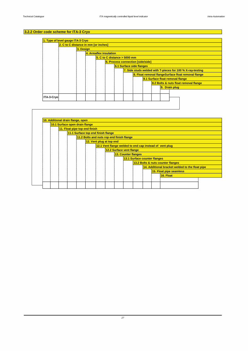
3.2.2 Order code scheme for ITA-3 Cryo
1. Type of level gauge ITA-3 Cryo2. C to C distance in mm [or inches]
3. Design
Technical Catalogue ITA magnetically controlled liquid level indicator Intra-Automation
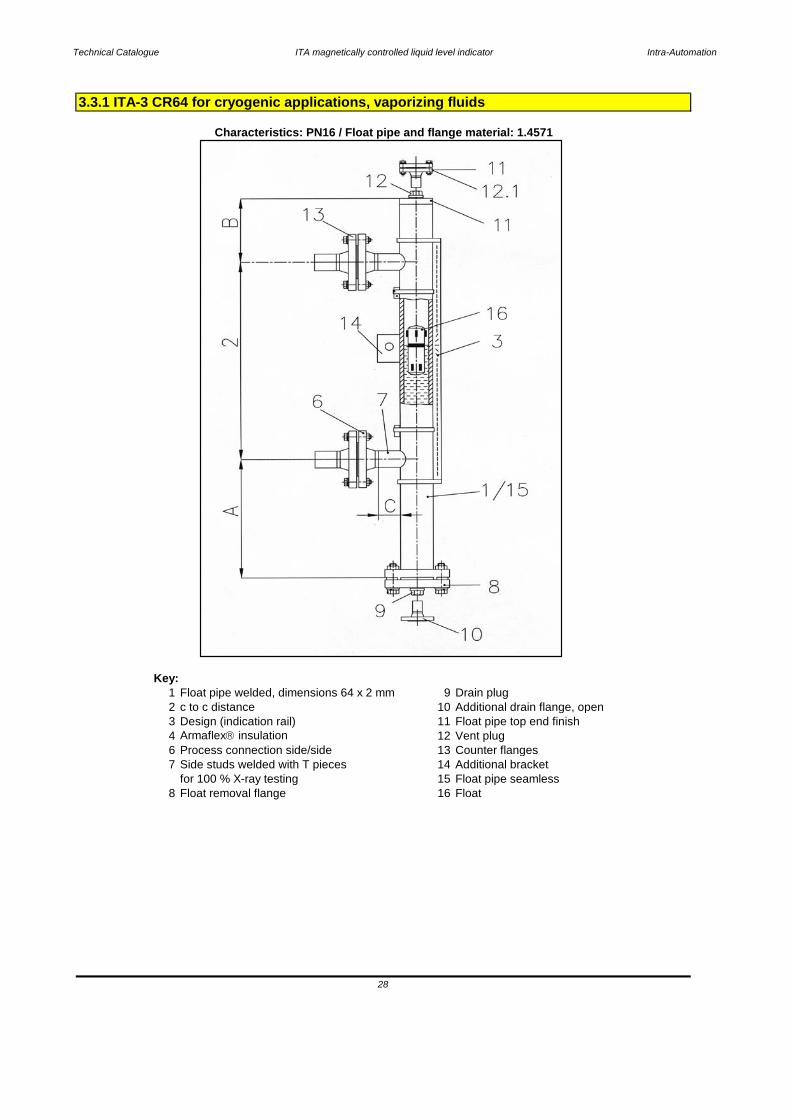
Key:1 Float pipe welded, dimensions 64 x 2 mm 9 Drain plug2 c to c distance 10 Additional drain flange, open3 Design (indication rail) 11 Float pipe top end finish4 Armaflex insulation 12 Vent plug6 Process connection side/side 13 Counter flanges7 Side studs welded with T pieces 14 Additional bracket
for 100 % X-ray testing 15 Float pipe seamless8 Float removal flange 16 Float
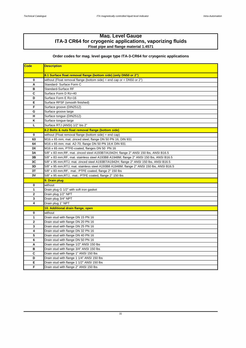
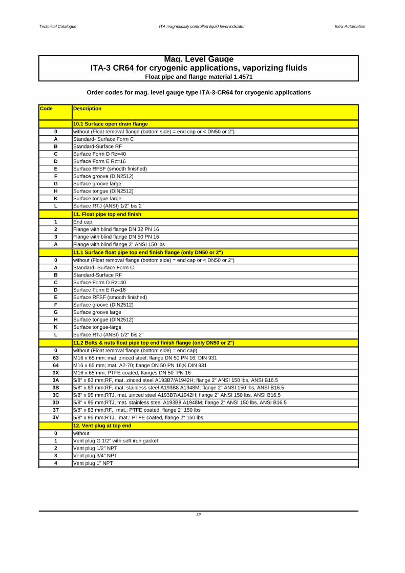
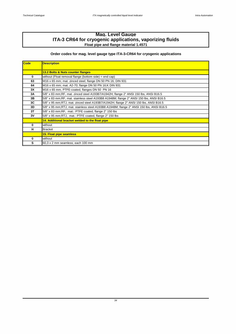
3.3.1 ITA-3 CR64 for cryogenic applications, vaporizing fluids
Characteristics: PN16 / Float pipe and flange material: 1.4571
28
Technical Catalogue ITA magnetically controlled liquid level indicator Intra-Automation
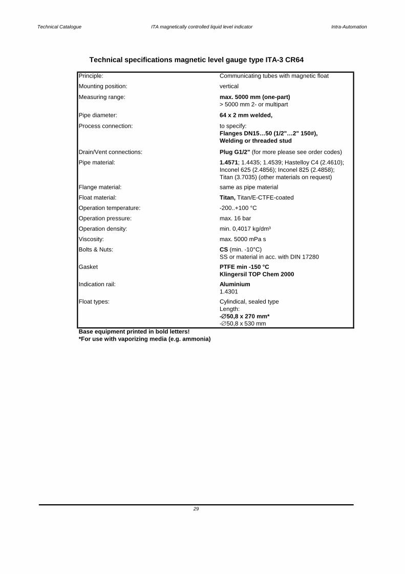
Base equipment printed in bold letters!*For use with vaporizing media (e.g. ammonia)
Float types: Cylindical, sealed typeLength:
29
-∅50,8 x 270 mm*-∅50,8 x 530 mm
Indication rail: Aluminium1.4301
SS or material in acc. with DIN 17280
Gasket PTFE min -150 °CKlingersil TOP Chem 2000
Bolts & Nuts: CS (min. -10°C)
Viscosity: max. 5000 mPa s
Operation density: min. 0,4017 kg/dm³
Operation temperature: -200..+100 °C
Operation pressure: max. 16 bar
Float material: Titan, Titan/E-CTFE-coated
Flange material: same as pipe material
Pipe material: 1.4571; 1.4435; 1.4539; Hastelloy C4 (2.4610); Inconel 625 (2.4856); Inconel 825 (2.4858);Titan (3.7035) (other materials on request)
Drain/Vent connections: Plug G1/2" (for more please see order codes)
Process connection: to specify:Flanges DN15…50 (1/2"…2" 150#),Welding or threaded stud
Measuring range: max. 5000 mm (one-part)> 5000 mm 2- or multipart
Pipe diameter: 64 x 2 mm welded,
Mounting position: vertical
Technical specifications magnetic level gauge type ITA-3 CR64
Principle: Communicating tubes with magnetic float

Technical Catalogue ITA magnetically controlled liquid level indicator Intra-Automation
Code Description
Mag. Level GaugeITA-3 CR64 for cryogenic applications, vaporizing fluids
Float pipe and flange material 1.4571
1. Float pipe welded Dimensions 64 x 2 mm
B > 5000 mm - with flange connection; DN 32 PN 16
Indication rail material: 1.4401 max. 400 °C, each 100 mm
4. Armaflex-Insulation2
< 5000 mm - without flange connection; DN 32 PN 16
5. C to C distance < 5000 mm
Order codes for mag. level gauge type ITA-3-CR64 for cryogenic applications
L C to C distance in mm
3. Design
1 Indication rail material: Aluminium max. 400 °C, each 100 mm
0
2. C to C distance
without indication rail each 100 mm
ITA-3 CR64
6. Process connection side/side
F Thickness: 12 mm, up to -15 °C
0 without insulation
R Thickness: 30 mm, up to -50 °C
T Thickness: 70 mm, up to -200 °C, incl. Makrolon window
A
6 Flanges DN 50 PN 16
Y Welding connection (please specify)
2 Flanges DN 20 PN 16
3 Flanges DN 25 PN 16
Z Threaded connection (please specify)
1 Flanges DN 15 PN 16
4 Flanges DN 32 PN 16
5 Flanges DN 40 PN 16
A Flanges 1/2" ANSI 150 lbs
Flanges 3/4" ANSI 150 lbs
C Flanges 1" ANSI 150 lbs
B
F Flanges 2" ANSI 150 lbs
D Flanges 1 1/4" ANSI 150 lbs
E Flanges 1 1/2" ANSI 150 lbs
Surface tongue (DIN2512)
7. Side studs welded with T-pieces for 100 % X-ray testing
6.1 Surface side flanges0 without
F Surface groove (DIN2512)
H
8. Float removal flange (bottom side)1 End cap (only if float removal flange (top side))
2 Flange DN 32 PN 16 incl. blind flange
0 without
T T-pieces
A Flange 2" ANSI 150 lbs incl. blind flange
Flange DN 50 PN 16 reinforced for shut off valve on side4
3 Flange DN 50 PN 16 incl. blind flange
B Flange 2" ANSI 150 lbs reinforced for shut off valve on side
3.3.2 Order codes ITA-3 CR64
30
Technical Catalogue ITA magnetically controlled liquid level indicator Intra-Automation
Code Description
3 Drain stud with flange DN 25 PN 16
1 Drain plug G 1/2" with soft iron gasket
4 Drain plug 1" NPT
0 without
1 Drain stud with flange DN 15 PN 16
2 Drain stud with flange DN 20 PN 16
3C 5/8" x 95 mm;RTJ, mat. zinced steel A193B7/A1942H; flange 2" ANSI 150 lbs, ANSI B16.5
3D 5/8" x 95 mm;RTJ, mat. stainless steel A193B8 A1948M; flange 2" ANSI 150 lbs, ANSI B16.5
3T 5/8" x 83 mm;RF, mat.: PTFE coated, flange 2" 150 lbs
3V 5/8" x 95 mm;RTJ, mat.: PTFE coated, flange 2" 150 lbs
3A 5/8" x 83 mm;RF, mat. zinced steel A193B7/A1942H; flange 2" ANSI 150 lbs, ANSI B16.5
3B 5/8" x 83 mm;RF, mat. stainless steel A193B8 A1948M; flange 2" ANSI 150 lbs, ANSI B16.5
M16 x 65 mm; mat. zinced steel; flange DN 50 PN 16; DIN 931
64 M16 x 65 mm; mat. A2-70; flange DN 50 PN 16;K DIN 931
3X M16 x 65 mm, PTFE-coated, flanges DN 50 PN 16
0 without (Float removal flange (bottom side) = end cap)
without (Float removal flange (bottom side) = end cap or < DN50 or 2")
A Standard- Surface Form C
8.1 Surface float removal flange (bottom side) (only DN50 or 2")0
Order codes for mag. level gauge type ITA-3-CR64 for cryogenic applications
B Standard-Surface RF
Surface tongue (DIN2512)
Surface RFSF (smooth finished)
F Surface groove (DIN2512)
G Surface groove large
HKL Surface RTJ (ANSI) 1/2" bis 2"
C Surface Form D Rz=40
D Surface Form E Rz=16
E
Surface tongue-large
8.2 Bolts & nuts float removal flange (bottom side)
0 without
10. Additional drain flange, open
9. Drain plug
2 Drain plug 1/2" NPT
3 Drain plug 3/4" NPT
63
4 Drain stud with flange DN 32 PN 16
Drain stud with flange DN 40 PN 16
Drain stud with flange 1 1/4" ANSI 150 lbs
6 Drain stud with flange DN 50 PN 16
5
DC Drain stud with flange 1" ANSI 150 lbs
E Drain stud with flange 1 1/2" ANSI 150 lbs
A Drain stud with flange 1/2" ANSI 150 lbs
Mag. Level GaugeITA-3 CR64 for cryogenic applications, vaporizing fluids
Float pipe and flange material 1.4571
F
B Drain stud with flange 3/4" ANSI 150 lbs
Drain stud with flange 2" ANSI 150 lbs
31
Technical Catalogue ITA magnetically controlled liquid level indicator Intra-Automation
Code Description
0 without
12. Vent plug at top end
4 Vent plug 1" NPT
3T 5/8" x 83 mm;RF, mat.: PTFE coated, flange 2" 150 lbs
3V 5/8" x 95 mm;RTJ, mat.: PTFE coated, flange 2" 150 lbs
3C 5/8" x 95 mm;RTJ, mat. zinced steel A193B7/A1942H; flange 2" ANSI 150 lbs, ANSI B16.5
3D 5/8" x 95 mm;RTJ, mat. stainless steel A193B8 A1948M; flange 2" ANSI 150 lbs, ANSI B16.5
3A 5/8" x 83 mm;RF, mat. zinced steel A193B7/A1942H; flange 2" ANSI 150 lbs, ANSI B16.5
3B 5/8" x 83 mm;RF, mat. stainless steel A193B8 A1948M; flange 2" ANSI 150 lbs, ANSI B16.5
64 M16 x 65 mm; mat. A2-70; flange DN 50 PN 16;K DIN 931
3X M16 x 65 mm, PTFE-coated, flanges DN 50 PN 16
63 M16 x 65 mm; mat. zinced steel; flange DN 50 PN 16; DIN 931
10.1 Surface open drain flange
A Standard- Surface Form C
0 without (Float removal flange (bottom side) = end cap or < DN50 or 2")
Order codes for mag. level gauge type ITA-3-CR64 for cryogenic applications
B Standard-Surface RF
C Surface Form D Rz=40
D Surface Form E Rz=16
E Surface RFSF (smooth finished)
L Surface RTJ (ANSI) 1/2" bis 2"
F Surface groove (DIN2512)
G Surface groove large
Surface tongue (DIN2512)
K Surface tongue-large
H
Standard- Surface Form C
11. Float pipe top end finish
11.1 Surface float pipe top end finish flange (only DN50 or 2")
Surface tongue-large
Surface groove (DIN2512)
Flange with blind flange 2" ANSI 150 lbs
1 End cap
2 Flange with blind flange DN 32 PN 16
A3 Flange with blind flange DN 50 PN 16
C Surface Form D Rz=40
B Standard-Surface RF
0 without (Float removal flange (bottom side) = end cap or < DN50 or 2")
A
E Surface RFSF (smooth finished)
D Surface Form E Rz=16
F
L
0 without (Float removal flange (bottom side) = end cap)
G Surface groove large
11.2 Bolts & nuts float pipe top end finish flange (only DN50 or 2")Surface RTJ (ANSI) 1/2" bis 2"
H Surface tongue (DIN2512)
K
2 Vent plug 1/2" NPT
1 Vent plug G 1/2" with soft iron gasket
3 Vent plug 3/4" NPT
ITA-3 CR64 for cryogenic applications, vaporizing fluidsFloat pipe and flange material 1.4571
Mag. Level Gauge
32

Technical Catalogue ITA magnetically controlled liquid level indicator Intra-Automation
Code Description
Flanged DN 20 PN 16 (socket weld construction to endcap)
5 Flanged DN 40 PN 16 (socket weld construction to endcap)
1 Flanged DN 15 PN 16 (socket weld construction to endcap)
2
0 without
12.1 Vent flange welded to end cap instead of vent plug
Flanged 1 1/4" ANSI 150 lbs (socket weld construction to endcap)
6 Flanged DN 50 PN 16 (socket weld construction to endcap)
3 Flanged DN 25 PN 16 (socket weld construction to endcap)
4 Flanged DN 32 PN 16 (socket weld construction to endcap)
A Flanged 1/2" ANSI 150 lbs (socket weld construction to endcap)
B
C Surface Form E Rz=16
B Surface Form D Rz=40
C Flanged 1" ANSI 150 lbs (socket weld construction to endcap)
D
Surface RF
E Flanged 1 1/2" ANSI 150 lbs (socket weld construction to endcap)
0 without (Vent flange welded to end cap = without)
A
12.2 Surface vent flange welded to end cap (only DN50 or 2")
G Surface tongue (DIN2512)
D Surface RFSF (ANSI)
E Surface groove (DIN2512)
F Surface groove large ANSI
Dichtfläche RTJ (ANSI)
13. Counter flanges
H Surface tongue-large ANSI
K Surface RTJ (ANSI) 1/2" bis 2"
L
C 1" 150 lbs
0 without
2 DN 20 PN 16
1 DN 15 PN 16
3 DN 25 PN 16
4 DN 32 PN 16
5 DN 40 PN 16
6 DN 50 PN 16
B 3/4" 150 lbs
A 1/2" 150 lbs
0 without (Counter flanges = without)
D 1 1/4" 150 lbs
E 1 1/2" 150 lbs
13.1 Surface counter flangesF 2" 150 lbs
F Surface groove (DIN2512)
H Surface tongue (DIN2512)
Mag. Level GaugeITA-3 CR64 for cryogenic applications, vaporizing fluids
Flanged 3/4" ANSI 150 lbs (socket weld construction to endcap)
33
Float pipe and flange material 1.4571
Order codes for mag. level gauge type ITA-3-CR64 for cryogenic applications
Technical Catalogue ITA magnetically controlled liquid level indicator Intra-Automation
Code Description
3V 5/8" x 95 mm;RTJ, mat.: PTFE coated, flange 2" 150 lbs
3D 5/8" x 95 mm;RTJ, mat. stainless steel A193B8 A1948M; flange 2" ANSI 150 lbs, ANSI B16.5
3T 5/8" x 83 mm;RF, mat.: PTFE coated, flange 2" 150 lbs
5/8" x 83 mm;RF, mat. zinced steel A193B7/A1942H; flange 2" ANSI 150 lbs, ANSI B16.5
3B 5/8" x 83 mm;RF, mat. stainless steel A193B8 A1948M; flange 2" ANSI 150 lbs, ANSI B16.5
3C 5/8" x 95 mm;RTJ, mat. zinced steel A193B7/A1942H; flange 2" ANSI 150 lbs, ANSI B16.5
63 M16 x 65 mm; mat. zinced steel; flange DN 50 PN 16; DIN 931
0 without (Float removal flange (bottom side) = end cap)
Float pipe and flange material 1.4571
Order codes for mag. level gauge type ITA-3-CR64 for cryogenic applications
ITA-3 CR64 for cryogenic applications, vaporizing fluids
Bracket
15. Float pipe seamless
13.2 Bolts & Nuts counter flanges
64 M16 x 65 mm; mat. A2-70; flange DN 50 PN 16;K DIN 931
3X M16 x 65 mm, PTFE-coated, flanges DN 50 PN 16
3A
S 60,3 x 2 mm seamless; each 100 mm
14. Additional bracket welded to the float pipe0 without
0 without
H
34
Mag. Level Gauge

Technical Catalogue ITA magnetically controlled liquid level indicator Intra-Automation
Code Pressure[bar]
Material Diameter[mm]
Length[mm]
min. Density[kg/dm³]
vented[Y/N]
Notes
3C0501K1 16 Titanium 50,8 525 0,4017 N with spacers;do not use for hydrogen or alcohol compounds
3C0501K2 16 Titanium 50,8 525 0,389 N with spacers;do not use for hydrogen or alcohol compounds
35
Mag. Level GaugeITA-3 CR64 for cryogenic applications, vaporizing fluids
Float pipe and flanges material: 1.4571
For additional accessories please refer to the chapters "Special equipment" and "Electrical accessories and Switches"
Order codes for mag. Level Gauges type: ITA-3-Cryo
DescriptionFloats

Technical Catalogue ITA magnetically controlled liquid level indicator Intra-Automation
36
15. Float pipe seamless16. Float
12.1 Vent flange welded to end cap instead of vent plug12.2 Surface vent flange
13. Counter flanges13.1 Surface counter flanges
13.2 Bolts & nuts counter flanges14. Additional bracket welded to the float pipe
10. Additional drain flange, open10.1 Surface open drain flange
11. Float pipe top end finish11.1 Surface top end finish flange
11.2 Bolts and nuts rop end finish flange12. Vent plug at top end
9. Drain plug
ITA-3-CR64
8.1 Surface float removal flange8.2 Bolts & nuts float removal flange
7. Side studs welded with T-pieces for 100 % X-ray-testing8. Float removal flangeSurface float removal flange
6. Process connection [side/side]6.1 Surface side flanges
4. Armaflex insulation5. C to C distance > 5000 mm
3.3.2 Order code scheme for ITA-3 Cryo
1. Type of level gauge ITA-3 CR642. C to C distance in mm [or inches]
3. Design
Technical Catalogue ITA magnetically controlled liquid level indicator Intra-Automation
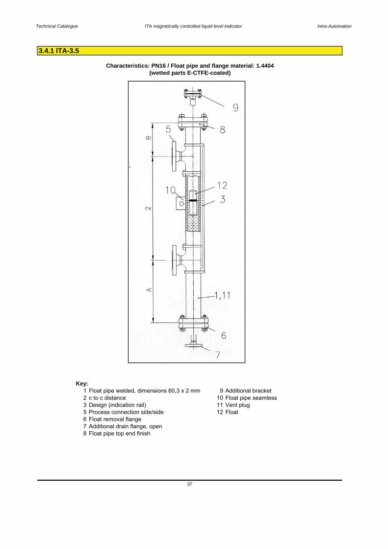
Key:1 Float pipe welded, dimensions 60,3 x 2 mm 9 Additional bracket2 c to c distance 10 Float pipe seamless3 Design (indication rail) 11 Vent plug5 Process connection side/side 12 Float6 Float removal flange7 Additional drain flange, open8 Float pipe top end finish
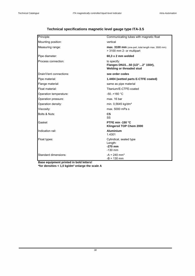
3.4.1 ITA-3.5
Characteristics: PN16 / Float pipe and flange material: 1.4404
37
(wetted parts E-CTFE-coated)
Technical Catalogue ITA magnetically controlled liquid level indicator Intra-Automation
Base equipment printed in bold letters!*for densities < 1,0 kg/dm³ enlarge the scale A
38
-B = 130 mmStandard dimensions: -A = 240 mm*
-130 mm
Float types: Cylindical, sealed typeLength: -270 mm
Indication rail: Aluminium1.4301
SSGasket PTFE min -150 °C
Klingersil TOP Chem 2000
Bolts & Nuts: CSViscosity: max. 5000 mPa s
Operation pressure: max. 16 bar
Operation density: min. 0,5645 kg/dm³
Operation temperature: -50..+160 °C
Pipe material: 1.4404 (wetted parts E-CTFE coated)
Float material: Titanium/E-CTFE-coated
Flange material: same as pipe material
Drain/Vent connections: see order codes
Process connection: to specify:Flanges DN15…50 (1/2"…2" 150#),Welding or threaded stud
Measuring range: max. 3100 mm (one-part, total length max. 3500 mm)> 3100 mm 2- or multipart
Pipe diameter: 60,3 x 2 mm welded
Mounting position: vertical
Technical specifications magnetic level gauge type ITA-3.5
Principle: Communicating tubes with magnetic float
Technical Catalogue ITA magnetically controlled liquid level indicator Intra-Automation
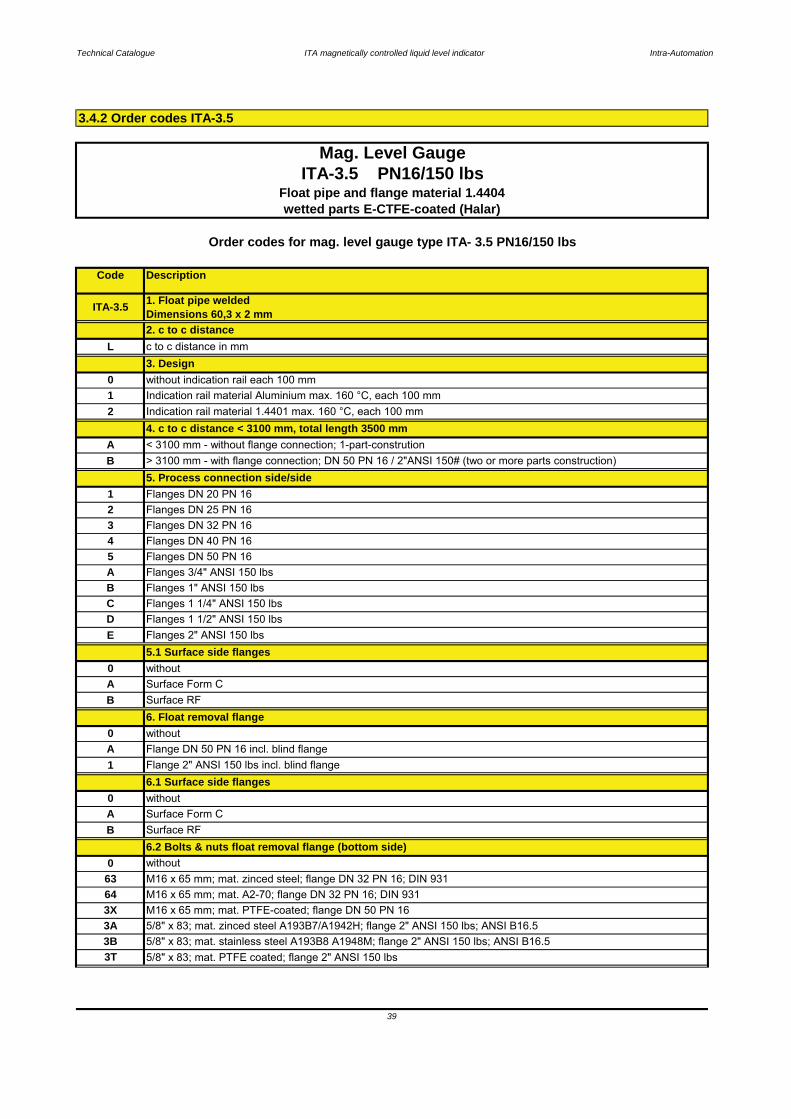
3.4.2 Order codes ITA-3.5
39
3T 5/8" x 83; mat. PTFE coated; flange 2" ANSI 150 lbs
64 M16 x 65 mm; mat. A2-70; flange DN 32 PN 16; DIN 9313X M16 x 65 mm; mat. PTFE-coated; flange DN 50 PN 163A 5/8" x 83; mat. zinced steel A193B7/A1942H; flange 2" ANSI 150 lbs; ANSI B16.53B 5/8" x 83; mat. stainless steel A193B8 A1948M; flange 2" ANSI 150 lbs; ANSI B16.5
6.2 Bolts & nuts float removal flange (bottom side)
63 M16 x 65 mm; mat. zinced steel; flange DN 32 PN 16; DIN 9310 without
E Flanges 2" ANSI 150 lbs
C Flanges 1 1/4" ANSI 150 lbsD Flanges 1 1/2" ANSI 150 lbs
A Flanges 3/4" ANSI 150 lbsB Flanges 1" ANSI 150 lbs
4 Flanges DN 40 PN 165 Flanges DN 50 PN 16
2 Flanges DN 25 PN 163 Flanges DN 32 PN 16
5. Process connection side/side1 Flanges DN 20 PN 16
A < 3100 mm - without flange connection; 1-part-construtionB > 3100 mm - with flange connection; DN 50 PN 16 / 2"ANSI 150# (two or more parts construction)
2 Indication rail material 1.4401 max. 160 °C, each 100 mm4. c to c distance < 3100 mm, total length 3500 mm
1 Indication rail material Aluminium max. 160 °C, each 100 mm
L c to c distance in mm3. Design
Mag. Level GaugeITA-3.5 PN16/150 lbs
Float pipe and flange material 1.4404wetted parts E-CTFE-coated (Halar)
Order codes for mag. level gauge type ITA- 3.5 PN16/150 lbs
0 without indication rail each 100 mm
Code Description
2. c to c distance
ITA-3.5 1. Float pipe weldedDimensions 60,3 x 2 mm
5.1 Surface side flanges
6. Float removal flange
0 withoutA Surface Form CB Surface RF
1 Flange 2" ANSI 150 lbs incl. blind flange6.1 Surface side flanges
0 withoutA Flange DN 50 PN 16 incl. blind flange
B Surface RF
0 withoutA Surface Form C
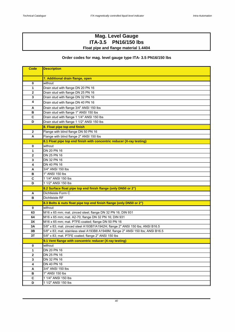
Technical Catalogue ITA magnetically controlled liquid level indicator Intra-Automation
40
B 1" ANSI 150 lbs
2 DN 25 PN 163 DN 32 PN 164 DN 40 PN 16A 3/4" ANSI 150 lbs
C 1 1/4" ANSI 150 lbsD 1 1/2" ANSI 150 lbs
9.1 Vent flange with concentric reducer (X-ray testing)
1 DN 20 PN 160 without
3B 5/8" x 83; mat. stainless steel A193B8 A1948M; flange 2" ANSI 150 lbs; ANSI B16.53T 5/8" x 83; mat. PTFE coated; flange 2" ANSI 150 lbs
3X M16 x 65 mm; mat. PTFE-coated; flange DN 50 PN 163A 5/8" x 83; mat. zinced steel A193B7/A1942H; flange 2" ANSI 150 lbs; ANSI B16.5
63 M16 x 65 mm; mat. zinced steel; flange DN 32 PN 16; DIN 93164 M16 x 65 mm; mat. A2-70; flange DN 32 PN 16; DIN 931
8.3 Bolts & nuts float pipe top end finish flange (only DN50 or 2")0 without
B Dichtleiste RF
D 1 1/2" ANSI 150 lbs8.2 Surface float pipe top end finish flange (only DN50 or 2")
A Dichtleiste Form C
10
BA
1" ANSI 150 lbsC 1 1/4" ANSI 150 lbs
3/4" ANSI 150 lbs
3 DN 32 PN 164 DN 40 PN 16
2
Order codes for mag. level gauge type ITA- 3.5 PN16/150 lbs
A
8.1 Float pipe top end finish with concentric reducer (X-ray testing)
DN 25 PN 16DN 20 PN 16without
2 Flange with blind flange DN 50 PN 16A Flange with blind flange 2" ANSI 150 lbs
C Drain stud with flange 1 1/4" ANSI 150 lbs
8. Float pipe top end finish
Code Description
Mag. Level GaugeITA-3.5 PN16/150 lbs
Float pipe and flange material 1.4404
D Drain stud with flange 1 1/2" ANSI 150 lbs
Drain stud with flange DN 32 PN 164 Drain stud with flange DN 40 PN 16
Drain stud with flange 3/4" ANSI 150 lbsB Drain stud with flange 1" ANSI 150 lbs
7. Additional drain flange, open
1 Drain stud with flange DN 20 PN 162 Drain stud with flange DN 25 PN 163
0 without
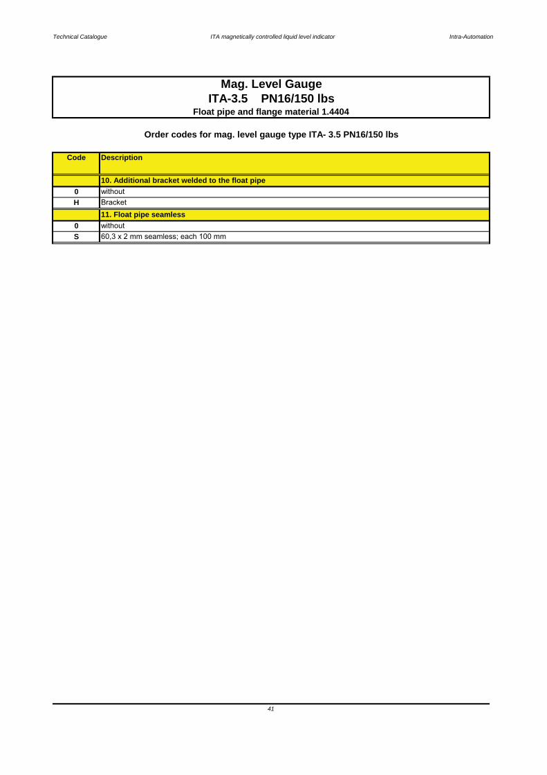
Technical Catalogue ITA magnetically controlled liquid level indicator Intra-Automation
41
Code Description
Mag. Level Gauge
11. Float pipe seamless
0 withoutBracket
S 60,3 x 2 mm seamless; each 100 mm0 without
H
10. Additional bracket welded to the float pipe
ITA-3.5 PN16/150 lbsFloat pipe and flange material 1.4404
Order codes for mag. level gauge type ITA- 3.5 PN16/150 lbs

Technical Catalogue ITA magnetically controlled liquid level indicator Intra-Automation
Code Pressure[bar]
Material Diameter[mm]
Length[mm]
min. Density[kg/dm³]
vented[Y/N]
Notes
35H024K1 16 Titanium,Halar-coated
52 240 0,6873 N
35H024K3 16 Titanium,Halar-coated
52 240 0,5645 N only with 316SS or Aluminium indication rail
42
Mag. Level GaugeITA-3.5 PN16/150 lbs
Float pipe and flanges material: 1.4404wetted parts E-CTFE-coated (Halar)
For additional accessories please refer to the chapters "Special equipment" and "Electrical accessories and Switches"
Order codes for mag. Level Gauges type: ITA-3.5 PN16/150 lbs
DescriptionFloats
Technical Catalogue ITA magnetically controlled liquid level indicator Intra-Automation
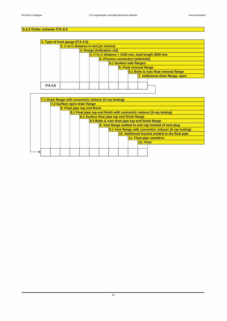
6.1 Bolts & nuts float removal flange
3.4.2 Order scheme ITA-3.5
8.2 Surface float pipe top end finish flange8.3 Bolts & nuts float pipe top end finish flange
5. Process connection [side/side]
8.1 Float pipe top end finish with concentric reducer (X-ray testing)
7.1 Drain flange with concentric reducer (X-ray testing)
6. Float removal flange
1. Type of level gauge [ITA-3.5]
3. Design [Indication rail]4. C to C distance > 3100 mm, total length 3500 mm
8. Float pipe top end finish
5.1 Surface side flanges
2. C to C distance in mm [or inches]
7.2 Surface open drain flange
43
10. Additional bracket welded to the float pipe11. Float pipe seamless
12. Float
9.1 Vent flange with concentric reducer (X-ray testing)
7. Addisional drain flange, open
9. Vent flange welded to end cap instead of vent plug
ITA-3.5
Technical Catalogue ITA magnetically controlled liquid level indicator Intra-Automation
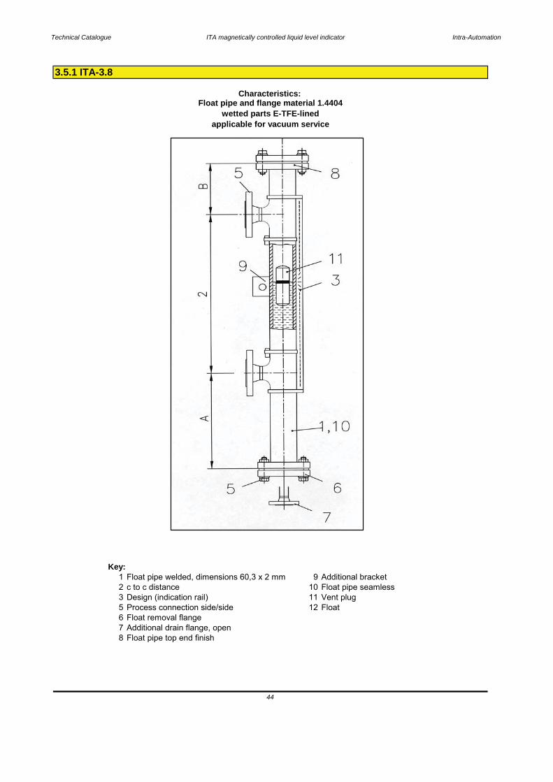
Key:1 Float pipe welded, dimensions 60,3 x 2 mm 9 Additional bracket2 c to c distance 10 Float pipe seamless3 Design (indication rail) 11 Vent plug5 Process connection side/side 12 Float6 Float removal flange7 Additional drain flange, open8 Float pipe top end finish
3.5.1 ITA-3.8
Characteristics: Float pipe and flange material 1.4404
wetted parts E-TFE-linedapplicable for vacuum service
44
Technical Catalogue ITA magnetically controlled liquid level indicator Intra-Automation
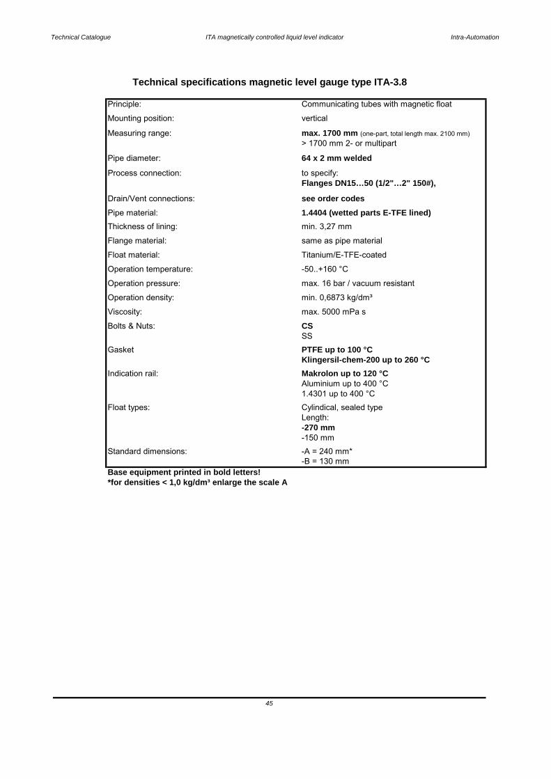
Base equipment printed in bold letters!*for densities < 1,0 kg/dm³ enlarge the scale A
Mounting position: vertical
Technical specifications magnetic level gauge type ITA-3.8
Principle: Communicating tubes with magnetic float
Pipe diameter: 64 x 2 mm welded
Measuring range: max. 1700 mm (one-part, total length max. 2100 mm)> 1700 mm 2- or multipart
Flanges DN15…50 (1/2"…2" 150#),Process connection: to specify:
Pipe material: 1.4404 (wetted parts E-TFE lined)Drain/Vent connections: see order codes
Float material: Titanium/E-TFE-coated
Flange material: same as pipe material
Operation pressure: max. 16 bar / vacuum resistant
Operation temperature: -50..+160 °C
Operation density: min. 0,6873 kg/dm³
SSBolts & Nuts: CSViscosity: max. 5000 mPa s
Indication rail: Makrolon up to 120 °C
Gasket PTFE up to 100 °CKlingersil-chem-200 up to 260 °C
Float types: Cylindical, sealed typeLength:
1.4301 up to 400 °C
Standard dimensions: -A = 240 mm*
-270 mm-150 mm
-B = 130 mm
45
Thickness of lining: min. 3,27 mm
Aluminium up to 400 °C
Technical Catalogue ITA magnetically controlled liquid level indicator Intra-Automation
Code Description
3T 5/8" x 83; mat. PTFE coated; flange 2" ANSI 150 lbs
3X M16 x 65 mm; mat. PTFE-coated; flange DN 50 PN 163A 5/8" x 83; mat. zinced steel A193B7/A1942H; flange 2" ANSI 150 lbs; ANSI B16.53B 5/8" x 83; mat. stainless steel A193B8 A1948M; flange 2" ANSI 150 lbs; ANSI B16.5
0 without
64 M16 x 65 mm; mat. A2-70; flange DN 32 PN 16; DIN 93163 M16 x 65 mm; mat. zinced steel; flange DN 32 PN 16; DIN 931
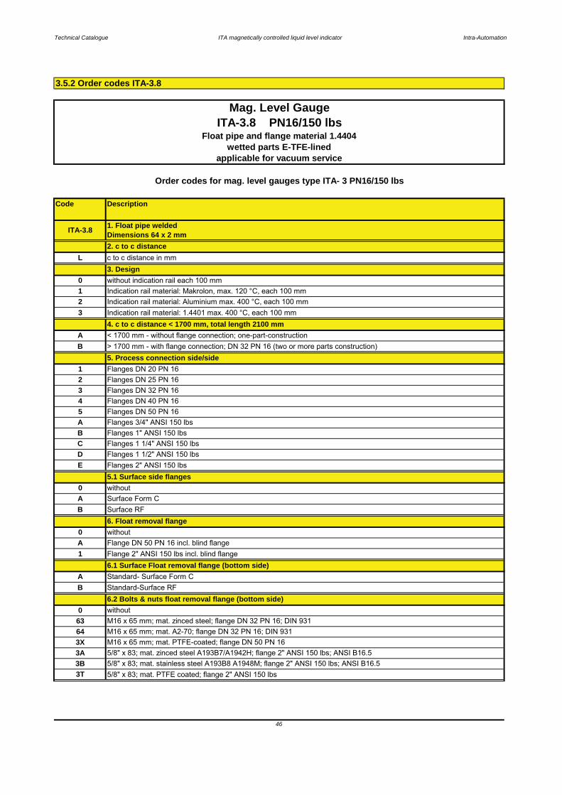
Standard- Surface Form C6.1 Surface Float removal flange (bottom side)
A
6.2 Bolts & nuts float removal flange (bottom side)B Standard-Surface RF
5 Flanges DN 50 PN 16
B Flanges 1" ANSI 150 lbsA Flanges 3/4" ANSI 150 lbs
5.1 Surface side flanges
Flanges DN 32 PN 16
Flanges 2" ANSI 150 lbs
C Flanges 1 1/4" ANSI 150 lbs
EFlanges 1 1/2" ANSI 150 lbsD
34 Flanges DN 40 PN 16
A < 1700 mm - without flange connection; one-part-construction
2 Flanges DN 25 PN 16
> 1700 mm - with flange connection; DN 32 PN 16 (two or more parts construction)B5. Process connection side/side
1 Flanges DN 20 PN 16
4. c to c distance < 1700 mm, total length 2100 mm
0 without indication rail each 100 mm
Indication rail material: Aluminium max. 400 °C, each 100 mm1 Indication rail material: Makrolon, max. 120 °C, each 100 mm2
2. c to c distance
3 Indication rail material: 1.4401 max. 400 °C, each 100 mm
L c to c distance in mm3. Design
Mag. Level GaugeITA-3.8 PN16/150 lbs
Order codes for mag. level gauges type ITA- 3 PN16/150 lbs
ITA-3.8 1. Float pipe weldedDimensions 64 x 2 mm
Float pipe and flange material 1.4404wetted parts E-TFE-lined
applicable for vacuum service
Surface RF6. Float removal flange
0 withoutA Surface Form C
3.5.2 Order codes ITA-3.8
46
1 Flange 2" ANSI 150 lbs incl. blind flange
0 withoutA Flange DN 50 PN 16 incl. blind flange
B

Technical Catalogue ITA magnetically controlled liquid level indicator Intra-Automation
Code Description
H Bracket
ITA-3.8 PN16/150 lbsFloat pipe and flange material 1.4404
wetted parts E-TFE-linedapplicable for vacuum service
1 Drain stud with flange DN 20 PN 16
7. Additional drain flange, open0 without
5/8" x 83; mat. PTFE coated; flange 2" ANSI 150 lbs
S 64 x 2 mm seamless; each 100 mm
0 without
0 without10. Float pipe seamless
Standard- Surface Form Cwithout
9. Additional bracket welded to the float pipe
3B 5/8" x 83; mat. stainless steel A193B8 A1948M; flange 2" ANSI 150 lbs; ANSI B16.5
3X M16 x 65 mm; mat. PTFE-coated; flange DN 50 PN 163A 5/8" x 83; mat. zinced steel A193B7/A1942H; flange 2" ANSI 150 lbs; ANSI B16.5
3T
64 M16 x 65 mm; mat. A2-70; flange DN 32 PN 16; DIN 931
F Flanged 2" ANSI 150 lbs (socket weld construction to blind flange)E Flanged 1 1/2" ANSI 150 lbs (socket weld construction to blind flange)
8.1 Surface vent flange0
8.2 Bolts & Nuts vent flange
D Flanged 1 1/4" ANSI 150 lbs (socket weld construction to blind flange)
B Flanged 3/4" ANSI 150 lbs (socket weld construction to blind flange)
63 M16 x 65 mm; mat. zinced steel; flange DN 32 PN 16; DIN 931
B Standard-Surface RFA
C Flanged 1" ANSI 150 lbs (socket weld construction to blind flange)
2 Flanged DN 20 PN 16 (socket weld construction to blind flange)
0 without
6 Flanged DN 50 PN 16 (socket weld construction to blind flange)A Flanged 1/2" ANSI 150 lbs (socket weld construction to blind flange)
0 without
5 Flanged DN 40 PN 16 (socket weld construction to blind flange)
3 Flanged DN 25 PN 16 (socket weld construction to blind flange)4 Flanged DN 32 PN 16 (socket weld construction to blind flange)
1 Flanged DN 15 PN 16 (socket weld construction to blind flange)
D Drain stud with flange 1 1/2" ANSI 150 lbs
Order codes for mag. level gauges type ITA- 3 PN16/150 lbs
8. Vent flange welded to blind flange
2 Drain stud with flange DN 25 PN 163 Drain stud with flange DN 32 PN 16
B
4 Drain stud with flange DN 40 PN 16
C
A Drain stud with flange 3/4" ANSI 150 lbs
Drain stud with flange 1 1/4" ANSI 150 lbsDrain stud with flange 1" ANSI 150 lbs
Mag. Level Gauge
47

Technical Catalogue ITA magnetically controlled liquid level indicator Intra-Automation
Code Pressure[bar]
Material Diameter[mm]
Length[mm]
min. Density[kg/dm³]
vented[Y/N]
Notes
34PVD1K1 10 PVDF 50 135 1,3000 N34PVD2K1 10 PVDF 50 255 0,8500 N
48
Mag. Level GaugeITA-3.8 PN16/150 lbs
Float pipe and flanges material: 1.4404wetted parts ETFE-lined
applicable for vacuum service
For additional accessories please refer to the chapters "Special equipment" and "Electrical accessories and Switches"
Order codes for mag. Level Gauges type: ITA-3.5 PN16/150 lbs
DescriptionFloats
Technical Catalogue ITA magnetically controlled liquid level indicator Intra-Automation
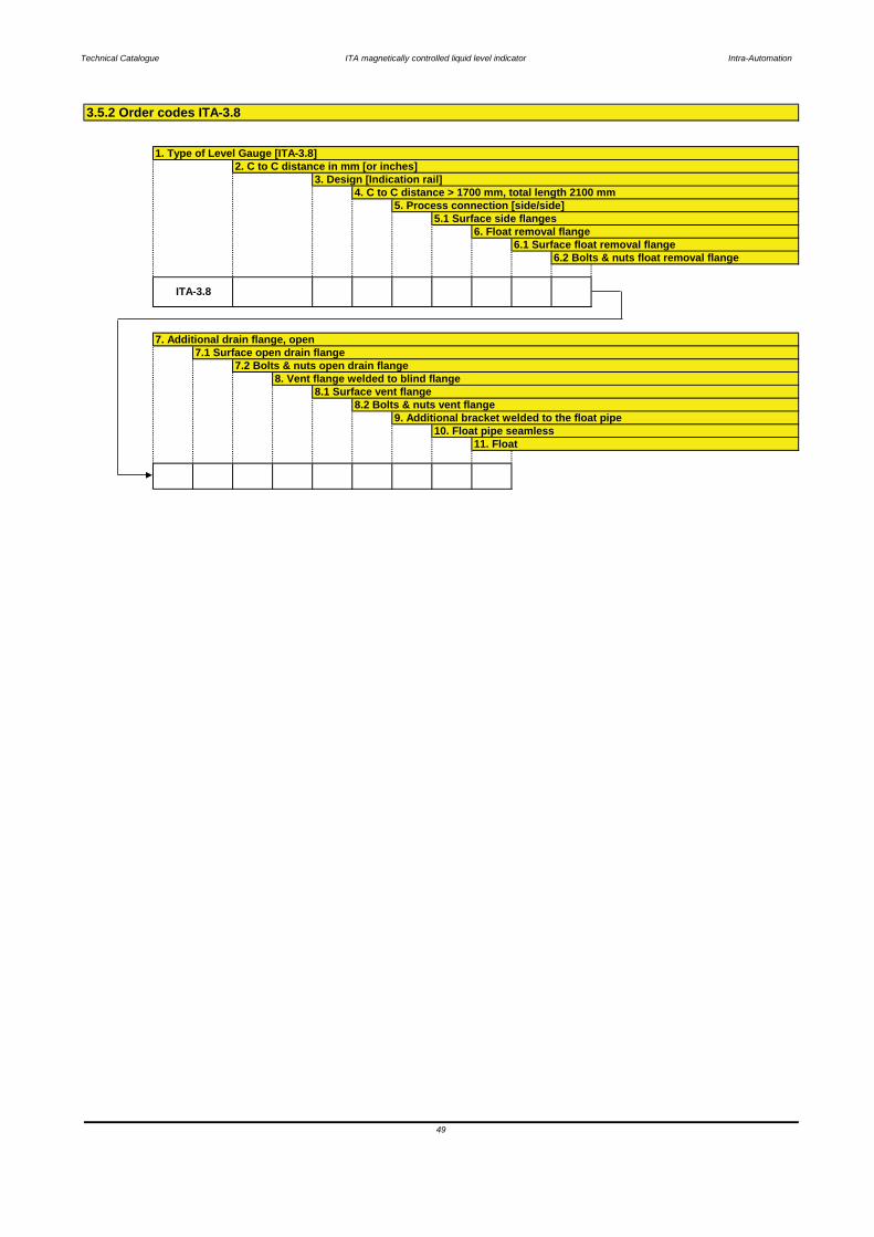
1. Type of Level Gauge [ITA-3.8]2. C to C distance in mm [or inches]
7.2 Bolts & nuts open drain flange7.1 Surface open drain flange
3. Design [Indication rail]
3.5.2 Order codes ITA-3.8
9. Additional bracket welded to the float pipe
5.1 Surface side flanges
10. Float pipe seamless
6. Float removal flange
8.1 Surface vent flange8. Vent flange welded to blind flange
4. C to C distance > 1700 mm, total length 2100 mm
8.2 Bolts & nuts vent flange
5. Process connection [side/side]
49
11. Float
6.1 Surface float removal flange6.2 Bolts & nuts float removal flange
7. Additional drain flange, open
ITA-3.8
Technical Catalogue ITA magnetically controlled liquid level indicator Intra-Automation
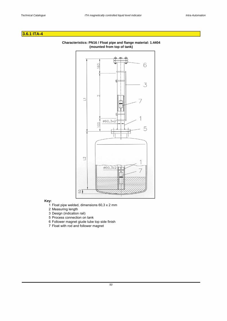
Key:1 Float pipe welded, dimensions 60,3 x 2 mm2 Measuring length3 Design (indication rail)5 Process connection on tank6 Follower magnet giude tube top side finish7 Float with rod and follower magnet
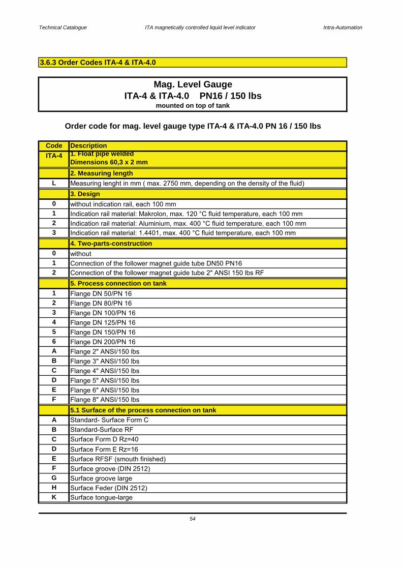
3.6.1 ITA-4
Characteristics: PN16 / Float pipe and flange material: 1.4404
50
(mounted from top of tank)

Technical Catalogue ITA magnetically controlled liquid level indicator Intra-Automation
Base equipment printed in bold letters!
Principle: Communicating tubes with magnetic float
Technical specifications magnetic level gauge type ITA-4
Measuring range: max. 2750 mm(depending on fluid's density)
Mounting position: Top of tank
necking connectionsPipe diameter: 60,3 x 2 mm welded,
Process connection: to specify:Flanges DN50 PN 16 pr 2" 150#
Pipe material: 1.4404; 1.4435; 1.4539; Hastelloy C4 (2.4610); Inconel 625 (2.4856); Inconel 825 (2.4858);
Drain/Vent connections: Plug R1/2"
Flange material: same as pipe materialTitan (3.7035) (other materials on request)
Operation temperature: -50..+400 °C
Float material: 1.4404Titan, Titan/E-CTFE-coated
Operation density: min. 0,68 kg/dm³
Operation pressure: max. 16 bar
Bolts & Nuts: CSViscosity: max. 5000 mPa s
Gasket PTFE up to 100 °CKlingersil C4400 up to 175 °C
SS
Indication rail: Makrolon up to 120 °CAluminium up to 400 °C
Graphit spiral wound up to 400 °C
Cylindical, sealed type, with rod1.4301 up to 400 °C
Float types:
51
Technical Catalogue ITA magnetically controlled liquid level indicator Intra-Automation
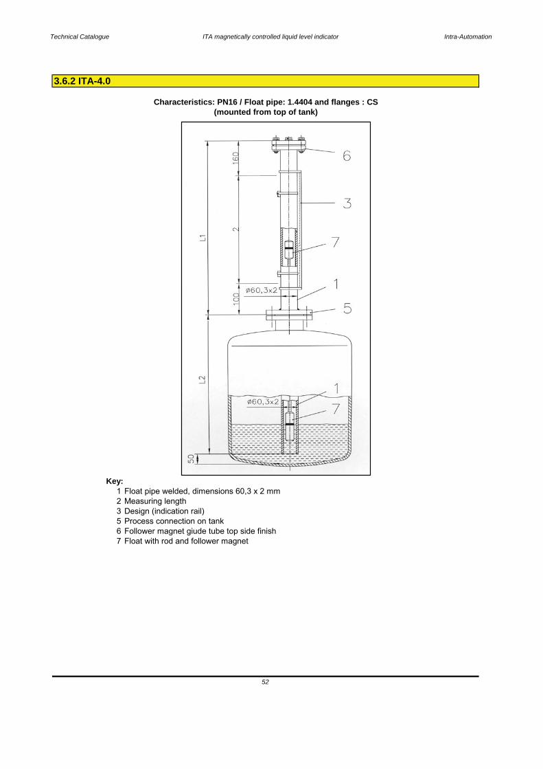
Key:1 Float pipe welded, dimensions 60,3 x 2 mm2 Measuring length3 Design (indication rail)5 Process connection on tank6 Follower magnet giude tube top side finish7 Float with rod and follower magnet
3.6.2 ITA-4.0
Characteristics: PN16 / Float pipe: 1.4404 and flanges : CS
52
(mounted from top of tank)
Technical Catalogue ITA magnetically controlled liquid level indicator Intra-Automation
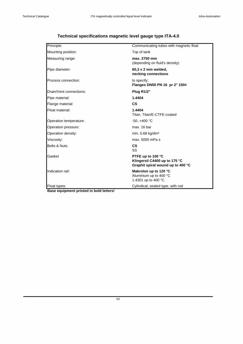
Base equipment printed in bold letters!Float types: Cylindical, sealed type, with rod
53
1.4301 up to 400 °C
Indication rail: Makrolon up to 120 °CAluminium up to 400 °C
Graphit spiral wound up to 400 °C
Gasket PTFE up to 100 °CKlingersil C4400 up to 175 °C
SSBolts & Nuts: CSViscosity: max. 5000 mPa s
Operation density: min. 0,68 kg/dm³
Operation pressure: max. 16 bar
Operation temperature: -50..+400 °C
Float material: 1.4404Titan, Titan/E-CTFE-coated
Flange material: CSPipe material: 1.4404Drain/Vent connections: Plug R1/2"
Flanges DN50 PN 16 pr 2" 150#Process connection: to specify:
Pipe diameter: 60,3 x 2 mm welded,necking connections
(depending on fluid's density)Measuring range: max. 2750 mm
Communicating tubes with magnetic float
Mounting position: Top of tank
Technical specifications magnetic level gauge type ITA-4.0
Principle:
Technical Catalogue ITA magnetically controlled liquid level indicator Intra-Automation
CodeITA-4
L
0123
012
123456ABCDEF
ABCDEFGHK
Connection of the follower magnet guide tube DN50 PN16
Surface tongue-large
Flange 6" ANSI/150 lbs
Surface Feder (DIN 2512)
Surface groove (DIN 2512)
Surface Form E Rz=16Surface RFSF (smouth finished)
Surface groove large
Flange DN 125/PN 16Flange DN 150/PN 16
without
Indication rail material: Aluminium, max. 400 °C fluid temperature, each 100 mmIndication rail material: 1.4401, max. 400 °C fluid temperature, each 100 mm
Mag. Level Gauge
mounted on top of tankITA-4 & ITA-4.0 PN16 / 150 lbs
4. Two-parts-construction
Measuring lenght in mm ( max. 2750 mm, depending on the density of the fluid)
Flange DN 200/PN 16Flange 2" ANSI/150 lbs
Connection of the follower magnet guide tube 2" ANSI 150 lbs RF5. Process connection on tankFlange DN 50/PN 16Flange DN 80/PN 16Flange DN 100/PN 16
Flange 4" ANSI/150 lbs
Surface Form D Rz=40
Flange 8" ANSI/150 lbs5.1 Surface of the process connection on tankStandard- Surface Form CStandard-Surface RF
Flange 5" ANSI/150 lbs
3.6.3 Order Codes ITA-4 & ITA-4.0
54
Order code for mag. level gauge type ITA-4 & ITA-4.0 PN 16 / 150 lbs
3. Designwithout indication rail, each 100 mmIndication rail material: Makrolon, max. 120 °C fluid temperature, each 100 mm
Description1. Float pipe weldedDimensions 60,3 x 2 mm2. Measuring length
Flange 3" ANSI/150 lbs
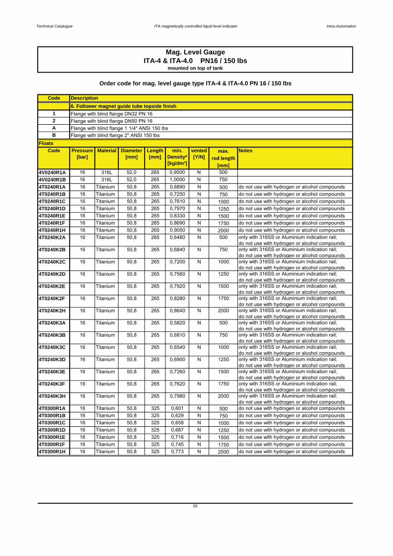
Technical Catalogue ITA magnetically controlled liquid level indicator Intra-Automation
Code
12AB
Code Pressure[bar]
Material Diameter[mm]
Length[mm]
min. Density*[kg/dm³]
vented[Y/N]
max.rod length
[mm]
Notes
4V0240R1A 16 316L 52,0 265 0,9500 N 5004V0240R1B 16 316L 52,0 265 1,0000 N 7504T0240R1A 16 Titanium 50,8 265 0,6890 N 500 do not use with hydrogen or alcohol compounds4T0240R1B 16 Titanium 50,8 265 0,7250 N 750 do not use with hydrogen or alcohol compounds4T0240R1C 16 Titanium 50,8 265 0,7610 N 1000 do not use with hydrogen or alcohol compounds4T0240R1D 16 Titanium 50,8 265 0,7970 N 1250 do not use with hydrogen or alcohol compounds4T0240R1E 16 Titanium 50,8 265 0,8330 N 1500 do not use with hydrogen or alcohol compounds4T0240R1F 16 Titanium 50,8 265 0,8690 N 1750 do not use with hydrogen or alcohol compounds4T0240R1H 16 Titanium 50,8 265 0,9050 N 2000 do not use with hydrogen or alcohol compounds4T0240K2A 16 Titanium 50,8 265 0,6480 N 500 only with 316SS or Aluminium indication rail;
do not use with hydrogen or alcohol compounds4T0240K2B 16 Titanium 50,8 265 0,6840 N 750 only with 316SS or Aluminium indication rail;
do not use with hydrogen or alcohol compounds4T0240K2C 16 Titanium 50,8 265 0,7200 N 1000 only with 316SS or Aluminium indication rail;
do not use with hydrogen or alcohol compounds4T0240K2D 16 Titanium 50,8 265 0,7560 N 1250 only with 316SS or Aluminium indication rail;
do not use with hydrogen or alcohol compounds4T0240K2E 16 Titanium 50,8 265 0,7920 N 1500 only with 316SS or Aluminium indication rail;
do not use with hydrogen or alcohol compounds4T0240K2F 16 Titanium 50,8 265 0,8280 N 1750 only with 316SS or Aluminium indication rail;
do not use with hydrogen or alcohol compounds4T0240K2H 16 Titanium 50,8 265 0,8640 N 2000 only with 316SS or Aluminium indication rail;
do not use with hydrogen or alcohol compounds4T0240K3A 16 Titanium 50,8 265 0,5820 N 500 only with 316SS or Aluminium indication rail;
do not use with hydrogen or alcohol compounds4T0240K3B 16 Titanium 50,8 265 0,6810 N 750 only with 316SS or Aluminium indication rail;
do not use with hydrogen or alcohol compounds4T0240K3C 16 Titanium 50,8 265 0,6540 N 1000 only with 316SS or Aluminium indication rail;
do not use with hydrogen or alcohol compounds4T0240K3D 16 Titanium 50,8 265 0,6900 N 1250 only with 316SS or Aluminium indication rail;
do not use with hydrogen or alcohol compounds4T0240K3E 16 Titanium 50,8 265 0,7260 N 1500 only with 316SS or Aluminium indication rail;
do not use with hydrogen or alcohol compounds4T0240K3F 16 Titanium 50,8 265 0,7620 N 1750 only with 316SS or Aluminium indication rail;
do not use with hydrogen or alcohol compounds4T0240K3H 16 Titanium 50,8 265 0,7980 N 2000 only with 316SS or Aluminium indication rail;
do not use with hydrogen or alcohol compounds4T0300R1A 16 Titanium 50,8 325 0,601 N 500 do not use with hydrogen or alcohol compounds4T0300R1B 16 Titanium 50,8 325 0,629 N 750 do not use with hydrogen or alcohol compounds4T0300R1C 16 Titanium 50,8 325 0,658 N 1000 do not use with hydrogen or alcohol compounds4T0300R1D 16 Titanium 50,8 325 0,687 N 1250 do not use with hydrogen or alcohol compounds4T0300R1E 16 Titanium 50,8 325 0,716 N 1500 do not use with hydrogen or alcohol compounds4T0300R1F 16 Titanium 50,8 325 0,745 N 1750 do not use with hydrogen or alcohol compounds4T0300R1H 16 Titanium 50,8 325 0,773 N 2000 do not use with hydrogen or alcohol compounds
Mag. Level GaugeITA-4 & ITA-4.0 PN16 / 150 lbs
mounted on top of tank
Order code for mag. level gauge type ITA-4 & ITA-4.0 PN 16 / 150 lbs
Floats
Description6. Follower magnet guide tube topside finishFlange with blind flange DN32 PN 16Flange with blind flange DN50 PN 16Flange with blind flange 1 1/4" ANSI 150 lbsFlange with blind flange 2" ANSI 150 lbs
55
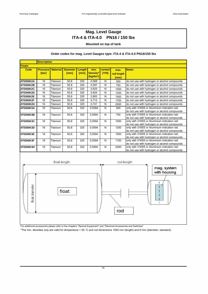
Technical Catalogue ITA magnetically controlled liquid level indicator Intra-Automation
Code Pressure[bar]
Material Diameter[mm]
Length[mm]
min. Density*[kg/dm³]
vented[Y/N]
max.rod length
[mm]
Notes
4T0300K2A 16 Titanium 50,8 325 0,568 N 500 do not use with hydrogen or alcohol compounds4T0300K2B 16 Titanium 50,8 325 0,597 N 750 do not use with hydrogen or alcohol compounds4T0300K2C 16 Titanium 50,8 325 0,625 N 1000 do not use with hydrogen or alcohol compounds4T0300K2D 16 Titanium 50,8 325 0,654 N 1250 do not use with hydrogen or alcohol compounds4T0300K2E 16 Titanium 50,8 325 0,683 N 1500 do not use with hydrogen or alcohol compounds4T0300K2F 16 Titanium 50,8 325 0,712 N 1750 do not use with hydrogen or alcohol compounds4T0300K2H 16 Titanium 50,8 325 0,741 N 2000 do not use with hydrogen or alcohol compounds4T0300K3A 16 Titanium 50,8 325 0,5594 N 500 only with 316SS or Aluminium indication rail;
do not use with hydrogen or alcohol compounds4T0300K3B 16 Titanium 50,8 325 0,5594 N 750 only with 316SS or Aluminium indication rail;
do not use with hydrogen or alcohol compounds4T0300K3C 16 Titanium 50,8 325 0,5594 N 1000 only with 316SS or Aluminium indication rail;
do not use with hydrogen or alcohol compounds4T0300K3D 16 Titanium 50,8 325 0,5594 N 1250 only with 316SS or Aluminium indication rail;
do not use with hydrogen or alcohol compounds4T0300K3E 16 Titanium 50,8 325 0,5594 N 1500 only with 316SS or Aluminium indication rail;
do not use with hydrogen or alcohol compounds4T0300K3F 16 Titanium 50,8 325 0,5594 N 1750 only with 316SS or Aluminium indication rail;
do not use with hydrogen or alcohol compounds4T0300K3H 16 Titanium 50,8 325 0,5594 N 2000 only with 316SS or Aluminium indication rail;
do not use with hydrogen or alcohol compounds
For additional accessories please refer to the chapters "Special Equipment" and "Electrical Accessories and Switches"
Mag. Level GaugeITA-4 & ITA-4.0 PN16 / 150 lbs
Mounted on top of tank
56
*The min. densities only are valid for temperature = 50 °C and rod dimensions 1000 mm (length) and 6 mm (diameter, standard).
Order codes for mag. Level Gauges type: ITA-4 & ITA-4.0 PN16/150 lbs
DescriptionFloats

Technical Catalogue ITA magnetically controlled liquid level indicator Intra-Automation
ITA-4
ITA-4.0
3.6.3 Order Codes ITA-4 & ITA-4.0
57
5. Process connection to tank5.1 Surface of process connection flange
6. Follower magnet guide tube topside finish7. Float
1. Type of Level Gauge2. Mesuring length in mm [or inches]
3. Design [Indication rail]4. Two-parts construction
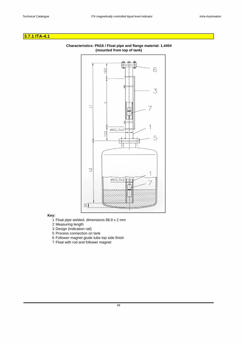
Technical Catalogue ITA magnetically controlled liquid level indicator Intra-Automation
Key:1 Float pipe welded, dimensions 88,9 x 2 mm2 Measuring length3 Design (indication rail)5 Process connection on tank6 Follower magnet giude tube top side finish7 Float with rod and follower magnet
3.7.1 ITA-4.1
Characteristics: PN16 / Float pipe and flange material: 1.4404(mounted from top of tank)
58
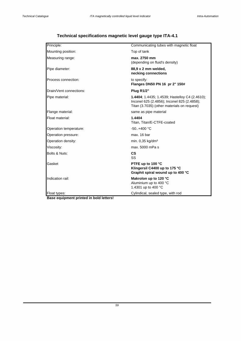
Technical Catalogue ITA magnetically controlled liquid level indicator Intra-Automation
Base equipment printed in bold letters!
59
Float types: Cylindical, sealed type, with rod
Aluminium up to 400 °C1.4301 up to 400 °C
Indication rail: Makrolon up to 120 °C
Klingersil C4400 up to 175 °CGraphit spiral wound up to 400 °C
Gasket PTFE up to 100 °C
Bolts & Nuts: CSSS
Operation density: min. 0,35 kg/dm³
Operation pressure: max. 16 bar
Operation temperature: -50..+400 °C
Titan, Titan/E-CTFE-coatedFloat material: 1.4404Flange material: same as pipe material
Inconel 625 (2.4856); Inconel 825 (2.4858);Titan (3.7035) (other materials on request)
Pipe material: 1.4404; 1.4435; 1.4539; Hastelloy C4 (2.4610);
Drain/Vent connections: Plug R1/2"
Process connection: to specify:Flanges DN50 PN 16 pr 2" 150#
Pipe diameter: 88,9 x 2 mm welded,
(depending on fluid's density)
Mounting position: Top of tank
necking connections
Measuring range: max. 2750 mm
Viscosity: max. 5000 mPa s
Technical specifications magnetic level gauge type ITA-4.1
Principle: Communicating tubes with magnetic float

Technical Catalogue ITA magnetically controlled liquid level indicator Intra-Automation
Key:1 Float pipe welded, dimensions 88,9 x 2 mm2 Measuring length3 Design (indication rail)5 Process connection on tank6 Follower magnet giude tube top side finish7 Float with rod and follower magnet
60
3.7.2 ITA-4.1.0
Characteristics: PN16 / Float pipe: 1.4404 and flanges : CS(mounted from top of tank)

Technical Catalogue ITA magnetically controlled liquid level indicator Intra-Automation
Base equipment printed in bold letters!Float types: Cylindical, sealed type, with rod
61
1.4301 up to 400 °C
Indication rail: Makrolon up to 120 °CAluminium up to 400 °C
Graphit spiral wound up to 400 °C
Gasket PTFE up to 100 °CKlingersil C4400 up to 175 °C
SSBolts & Nuts: CSViscosity: max. 5000 mPa s
Operation density: min. 0,35 kg/dm³
Operation pressure: max. 16 bar
Operation temperature: -50..+400 °C
Float material: 1.4404Titan, Titan/E-CTFE-coated
Flange material: CSPipe material: 1.4404Drain/Vent connections: Plug R1/2"
Flanges DN50 PN 16 pr 2" 150#Process connection: to specify:
Pipe diameter: 88,9 x 2 mm welded,necking connections
(depending on fluid's density)Measuring range: max. 2750 mm
Mounting position: Top of tank
Technical specifications magnetic level gauge type ITA-4.1.0
Principle: Communicating tubes with magnetic float
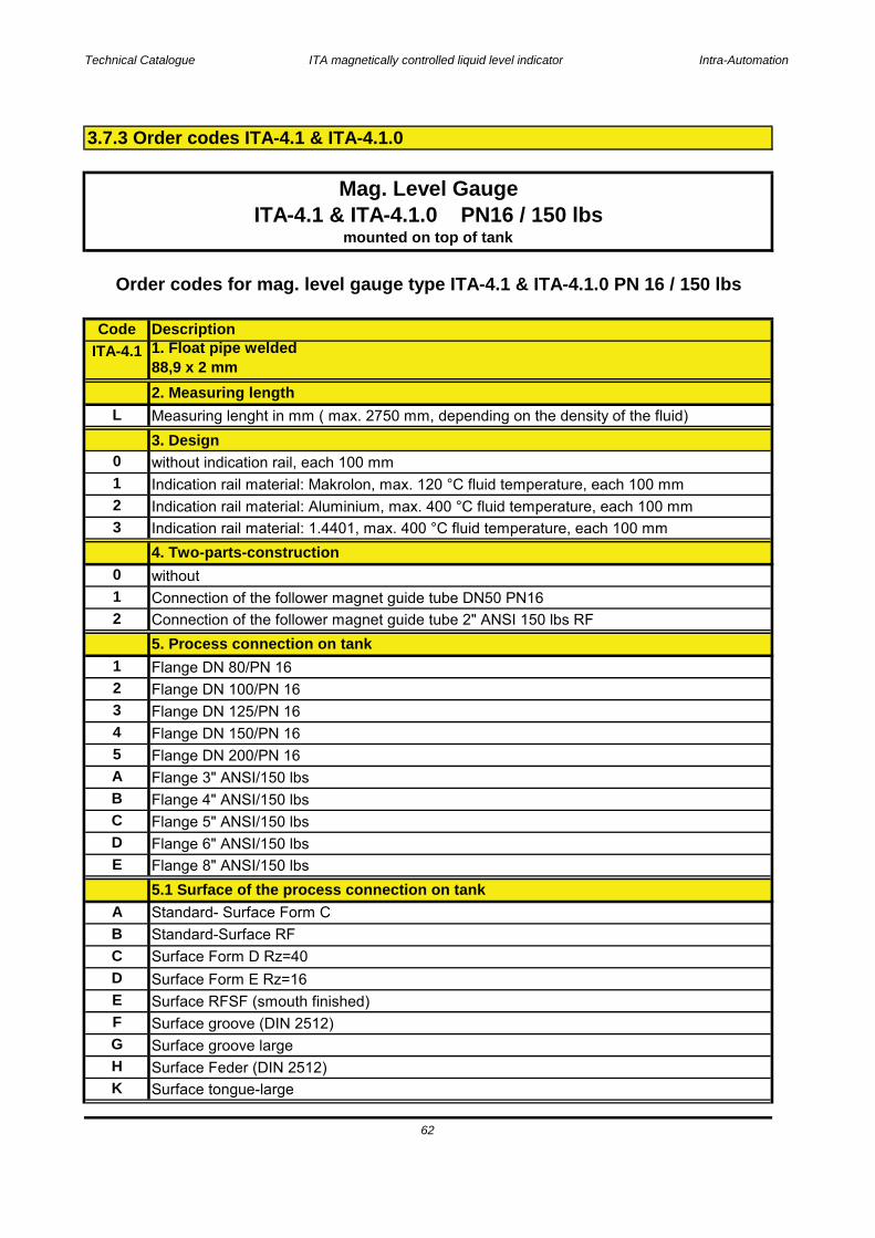
Technical Catalogue ITA magnetically controlled liquid level indicator Intra-Automation
CodeITA-4.1
L
0123
012
12345ABCDE
ABCDEFGHK
Standard-Surface RFSurface Form D Rz=40
5. Process connection on tankConnection of the follower magnet guide tube 2" ANSI 150 lbs RF
Surface RFSF (smouth finished)Surface groove (DIN 2512)
Surface Form E Rz=16
Flange DN 150/PN 16Flange DN 200/PN 16Flange 3" ANSI/150 lbs
Surface groove largeSurface Feder (DIN 2512)Surface tongue-large
Mag. Level GaugeITA-4.1 & ITA-4.1.0 PN16 / 150 lbs
mounted on top of tank
5.1 Surface of the process connection on tankStandard- Surface Form C
Flange DN 100/PN 16Flange DN 80/PN 16
Flange 4" ANSI/150 lbsFlange 5" ANSI/150 lbsFlange 6" ANSI/150 lbsFlange 8" ANSI/150 lbs
Indication rail material: Makrolon, max. 120 °C fluid temperature, each 100 mmIndication rail material: Aluminium, max. 400 °C fluid temperature, each 100 mmIndication rail material: 1.4401, max. 400 °C fluid temperature, each 100 mm4. Two-parts-constructionwithoutConnection of the follower magnet guide tube DN50 PN16
3.7.3 Order codes ITA-4.1 & ITA-4.1.0
62
Order codes for mag. level gauge type ITA-4.1 & ITA-4.1.0 PN 16 / 150 lbs
2. Measuring lengthMeasuring lenght in mm ( max. 2750 mm, depending on the density of the fluid)3. Design
Description1. Float pipe welded88,9 x 2 mm
Flange DN 125/PN 16
without indication rail, each 100 mm
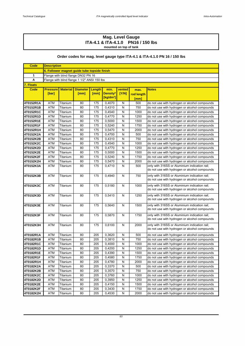
Technical Catalogue ITA magnetically controlled liquid level indicator Intra-Automation
Code
1A
Code Pressure[bar]
Material Diameter[mm]
Length[mm]
min. Density*[kg/dm³]
vented[Y/N]
max.rod length
[mm]
Notes
4T0152R1A ATM Titanium 80 175 0,4070 N 500 do not use with hydrogen or alcohol compounds4T0152R1B ATM Titanium 80 175 0,4310 N 750 do not use with hydrogen or alcohol compounds4T0152R1C ATM Titanium 80 175 0,4540 N 1000 do not use with hydrogen or alcohol compounds4T0152R1D ATM Titanium 80 175 0,4770 N 1250 do not use with hydrogen or alcohol compounds4T0152R1E ATM Titanium 80 175 0,5000 N 1500 do not use with hydrogen or alcohol compounds4T0152R1F ATM Titanium 80 175 0,5240 N 1750 do not use with hydrogen or alcohol compounds4T0152R1H ATM Titanium 80 175 0,5470 N 2000 do not use with hydrogen or alcohol compounds4T0152K2A ATM Titanium 80 175 0,4700 N 500 do not use with hydrogen or alcohol compounds4T0152K2B ATM Titanium 80 175 0,4310 N 750 do not use with hydrogen or alcohol compounds4T0152K2C ATM Titanium 80 175 0,4540 N 1000 do not use with hydrogen or alcohol compounds4T0152K2D ATM Titanium 80 175 0,4770 N 1250 do not use with hydrogen or alcohol compounds4T0152K2E ATM Titanium 80 175 0,5000 N 1500 do not use with hydrogen or alcohol compounds4T0152K2F ATM Titanium 80 175 0,5240 N 1750 do not use with hydrogen or alcohol compounds4T0152K2H ATM Titanium 80 175 0,5470 N 2000 do not use with hydrogen or alcohol compounds4T0152K3A ATM Titanium 80 175 0,4710 N 500 only with 316SS or Aluminium indication rail;
do not use with hydrogen or alcohol compounds
4T0152K3B ATM Titanium 80 175 0,4940 N 750 only with 316SS or Aluminium indication rail;do not use with hydrogen or alcohol compounds
4T0152K3C ATM Titanium 80 175 0,5180 N 1000 only with 316SS or Aluminium indication rail;do not use with hydrogen or alcohol compounds
4T0152K3D ATM Titanium 80 175 0,5410 N 1250 only with 316SS or Aluminium indication rail;do not use with hydrogen or alcohol compounds
4T0152K3E ATM Titanium 80 175 0,5640 N 1500 only with 316SS or Aluminium indication rail;do not use with hydrogen or alcohol compounds
4T0152K3F ATM Titanium 80 175 0,5870 N 1750 only with 316SS or Aluminium indication rail;do not use with hydrogen or alcohol compounds
4T0152K3H ATM Titanium 80 175 0,6100 N 2000 only with 316SS or Aluminium indication rail;do not use with hydrogen or alcohol compounds
4T0182R1A ATM Titanium 80 205 0,3620 N 500 do not use with hydrogen or alcohol compounds4T0182R1B ATM Titanium 80 205 0,3810 N 750 do not use with hydrogen or alcohol compounds4T0182R1C ATM Titanium 80 205 0,4000 N 1000 do not use with hydrogen or alcohol compounds4T0182R1D ATM Titanium 80 205 0,4200 N 1250 do not use with hydrogen or alcohol compounds4T0182R1E ATM Titanium 80 205 0,4390 N 1500 do not use with hydrogen or alcohol compounds4T0182R1F ATM Titanium 80 205 0,4580 N 1750 do not use with hydrogen or alcohol compounds4T0182R1H ATM Titanium 80 205 0,4780 N 2000 do not use with hydrogen or alcohol compounds4T0182K2A ATM Titanium 80 205 0,3370 N 500 do not use with hydrogen or alcohol compounds4T0182K2B ATM Titanium 80 205 0,3570 N 750 do not use with hydrogen or alcohol compounds4T0182K2C ATM Titanium 80 205 0,3760 N 1000 do not use with hydrogen or alcohol compounds4T0182K2D ATM Titanium 80 205 0,3950 N 1250 do not use with hydrogen or alcohol compounds4T0182K2E ATM Titanium 80 205 0,4150 N 1500 do not use with hydrogen or alcohol compounds4T0182K2F ATM Titanium 80 205 0,3430 N 1750 do not use with hydrogen or alcohol compounds4T0182K2H ATM Titanium 80 205 0,4530 N 2000 do not use with hydrogen or alcohol compounds
Description6. Follower magnet guide tube topside finishFlange with blind flange DN32 PN 16Flange with blind flange 1 1/2" ANSI 150 lbs
7. Floats
63
Mag. Level GaugeITA-4.1 & ITA-4.1.0 PN16 / 150 lbs
mounted on top of tank
Order codes for mag. level gauge type ITA-4.1 & ITA-4.1.0 PN 16 / 150 lbs

Technical Catalogue ITA magnetically controlled liquid level indicator Intra-Automation
Code Pressure[bar]
Material Diameter[mm]
Length[mm]
min. Density*[kg/dm³]
vented[Y/N]
max.rod length
[mm]
Notes
4T0182K3A ATM Titanium 80 205 0,3000 N 500 only with 316SS or Aluminium indication rail;do not use with hydrogen or alcohol compounds
4T0182K3B ATM Titanium 80 205 0,3190 N 750 only with 316SS or Aluminium indication rail;do not use with hydrogen or alcohol compounds
4T0182K3C ATM Titanium 80 205 0,3380 N 1000 only with 316SS or Aluminium indication rail;do not use with hydrogen or alcohol compounds
4T0182K3D ATM Titanium 80 205 0,3580 N 1250 only with 316SS or Aluminium indication rail;do not use with hydrogen or alcohol compounds
4T0182K3E ATM Titanium 80 205 0,3770 N 1500 only with 316SS or Aluminium indication rail;do not use with hydrogen or alcohol compounds
4T0182K3F ATM Titanium 80 205 0,3960 N 1750 only with 316SS or Aluminium indication rail;do not use with hydrogen or alcohol compounds
4T0182K3H ATM Titanium 80 205 0,4160 N 2000 only with 316SS or Aluminium indication rail;do not use with hydrogen or alcohol compounds
4T0242R1A ATM Titanium 80 265 0,2980 N 500 do not use with hydrogen or alcohol compounds4T0242R1B ATM Titanium 80 265 0,3120 N 750 do not use with hydrogen or alcohol compounds4T0242R1C ATM Titanium 80 265 0,3270 N 1000 do not use with hydrogen or alcohol compounds4T0242R1D ATM Titanium 80 265 0,3410 N 1250 do not use with hydrogen or alcohol compounds4T0242R1E ATM Titanium 80 265 0,3560 N 1500 do not use with hydrogen or alcohol compounds4T0242R1F ATM Titanium 80 265 0,3700 N 1750 do not use with hydrogen or alcohol compounds4T0242R1H ATM Titanium 80 265 0,3850 N 2000 do not use with hydrogen or alcohol compounds4T0242K2A ATM Titanium 80 265 0,2800 N 500 do not use with hydrogen or alcohol compounds4T0242K2B ATM Titanium 80 265 0,2940 N 750 do not use with hydrogen or alcohol compounds4T0242K2C ATM Titanium 80 265 0,3090 N 1000 do not use with hydrogen or alcohol compounds4T0242K2D ATM Titanium 80 265 0,3230 N 1250 do not use with hydrogen or alcohol compounds4T0242K2E ATM Titanium 80 265 0,3380 N 1500 do not use with hydrogen or alcohol compounds4T0242K2F ATM Titanium 80 265 0,3520 N 1750 do not use with hydrogen or alcohol compounds4T0242K2H ATM Titanium 80 265 0,3670 N 2000 do not use with hydrogen or alcohol compounds4T0242K3A ATM Titanium 80 265 0,2530 N 500 only with 316SS or Aluminium indication rail;
do not use with hydrogen or alcohol compounds
4T0242K3B ATM Titanium 80 265 0,2680 N 750 only with 316SS or Aluminium indication rail;do not use with hydrogen or alcohol compounds
4T0242K3C ATM Titanium 80 265 0,2820 N 1000 only with 316SS or Aluminium indication rail;do not use with hydrogen or alcohol compounds
4T0242K3D ATM Titanium 80 265 0,2970 N 1250 only with 316SS or Aluminium indication rail;do not use with hydrogen or alcohol compounds
4T0242K3E ATM Titanium 80 265 0,3110 N 1500 only with 316SS or Aluminium indication rail;do not use with hydrogen or alcohol compounds
4T0242K3F ATM Titanium 80 265 0,3260 N 1750 only with 316SS or Aluminium indication rail;do not use with hydrogen or alcohol compounds
4T0242K3H ATM Titanium 80 265 0,3400 N 2000 only with 316SS or Aluminium indication rail;do not use with hydrogen or alcohol compounds
Order codes for mag. Level Gauges type: ITA-4.1 & ITA-4.1.0 PN16/150 lbs
DescriptionFloats
64
ITA-4.1 & ITA-4.1.0 PN16 / 150 lbsMounted on top of tank
Mag. Level Gauge
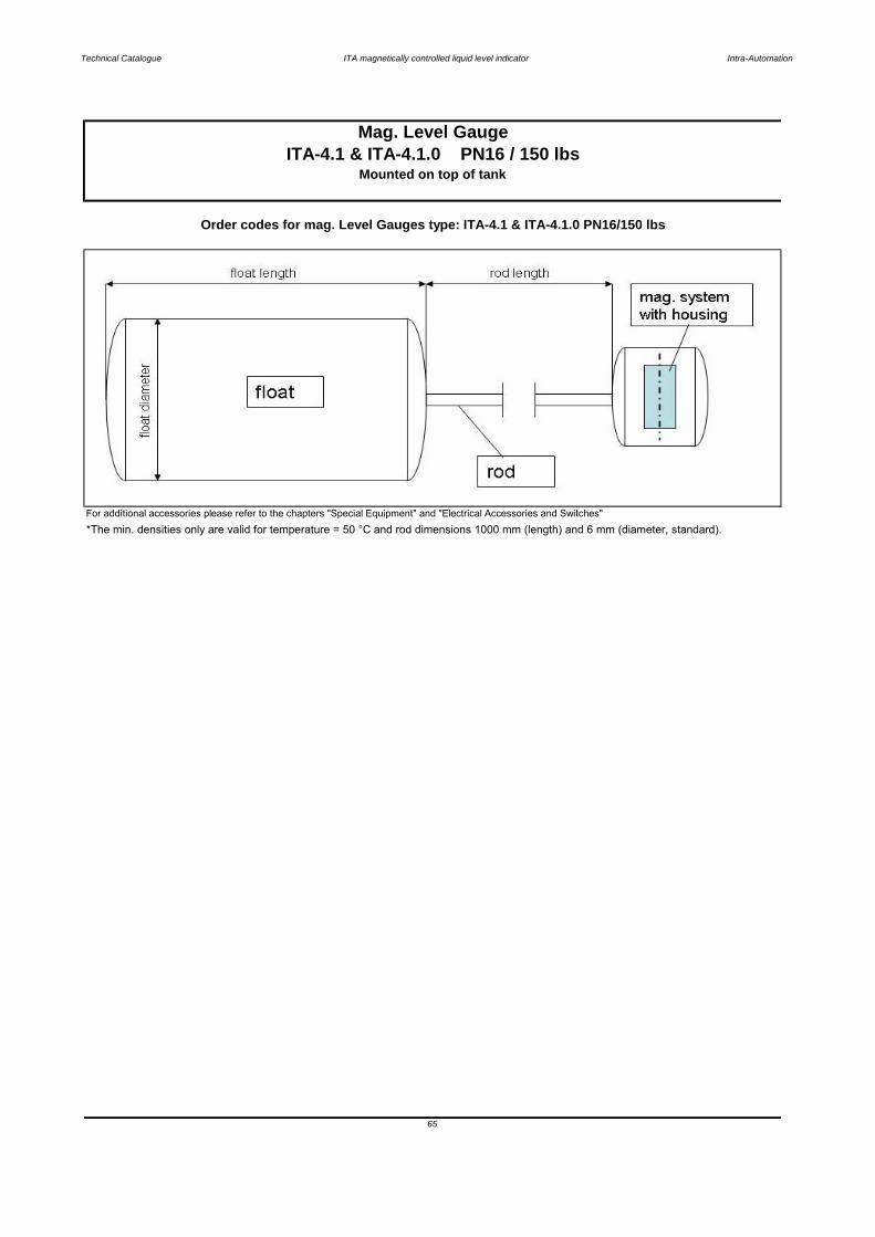
Technical Catalogue ITA magnetically controlled liquid level indicator Intra-Automation
For additional accessories please refer to the chapters "Special Equipment" and "Electrical Accessories and Switches"
65
Mag. Level GaugeITA-4.1 & ITA-4.1.0 PN16 / 150 lbs
Mounted on top of tank
Order codes for mag. Level Gauges type: ITA-4.1 & ITA-4.1.0 PN16/150 lbs
*The min. densities only are valid for temperature = 50 °C and rod dimensions 1000 mm (length) and 6 mm (diameter, standard).
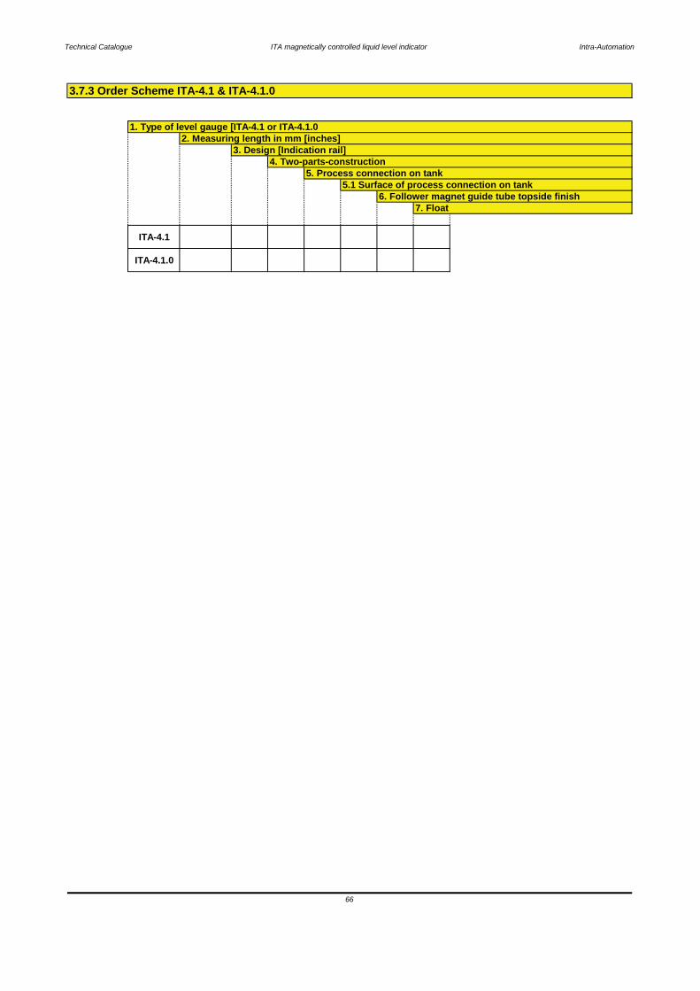
Technical Catalogue ITA magnetically controlled liquid level indicator Intra-Automation
ITA-4.1
ITA-4.1.0
7. Float
3.7.3 Order Scheme ITA-4.1 & ITA-4.1.0
66
4. Two-parts-construction5. Process connection on tank
5.1 Surface of process connection on tank6. Follower magnet guide tube topside finish
1. Type of level gauge [ITA-4.1 or ITA-4.1.02. Measuring length in mm [inches]
3. Design [Indication rail]

Technical Catalogue ITA magnetically controlled liquid level indicator Intra-Automation
Key:1 Float pipe welded, dimensions 60,3 x 2 mm2 Distance between process connections3 Design (indication rail)5 Process connection top side6 Process connection bottom side7 Float removal flange
3.8.1 ITA-5
Characteristics: PN16 / Float pipe and flange material: 1.4404
67
(Process connections top/bottom)
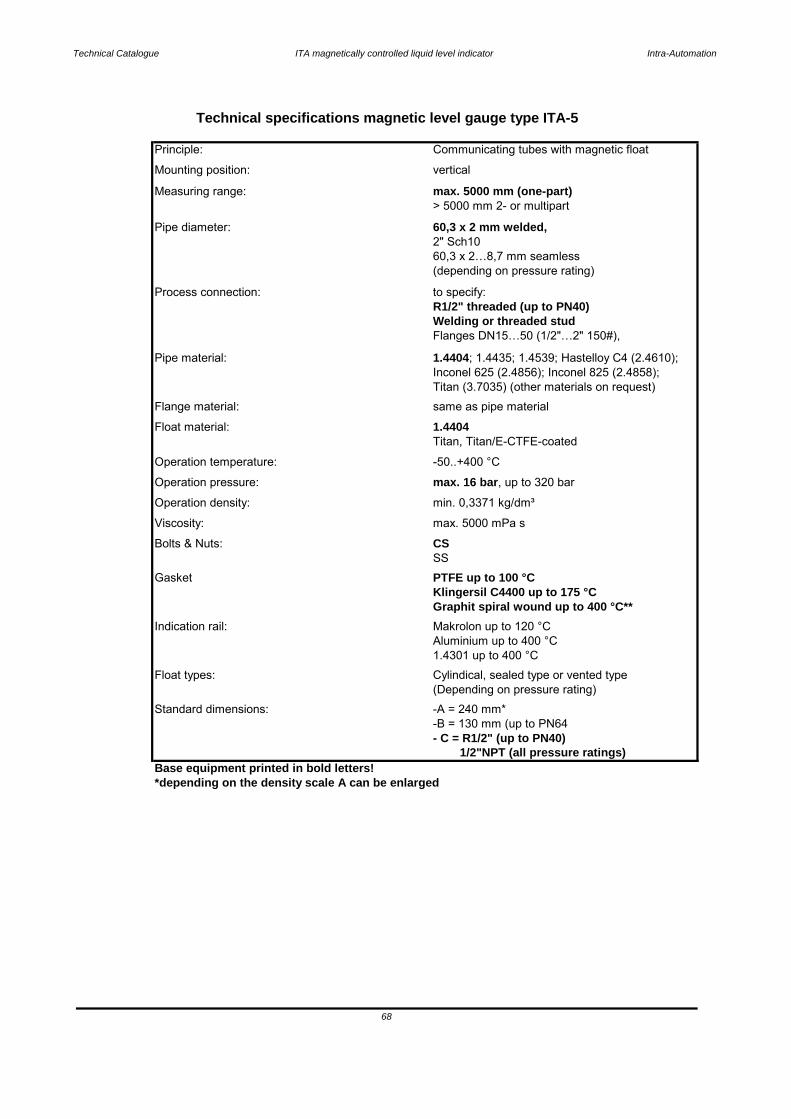
Technical Catalogue ITA magnetically controlled liquid level indicator Intra-Automation
1/2"NPT (all pressure ratings)Base equipment printed in bold letters!*depending on the density scale A can be enlarged
Technical specifications magnetic level gauge type ITA-5
Viscosity: max. 5000 mPa s
Mounting position: vertical
Principle: Communicating tubes with magnetic float
Pipe diameter: 60,3 x 2 mm welded,
Measuring range: max. 5000 mm (one-part)> 5000 mm 2- or multipart
(depending on pressure rating)60,3 x 2…8,7 mm seamless2" Sch10
Process connection: to specify:
Flanges DN15…50 (1/2"…2" 150#),Welding or threaded stud
Inconel 625 (2.4856); Inconel 825 (2.4858);Titan (3.7035) (other materials on request)
Pipe material: 1.4404; 1.4435; 1.4539; Hastelloy C4 (2.4610);
Float material: 1.4404Flange material: same as pipe material
Operation temperature: -50..+400 °C
Titan, Titan/E-CTFE-coated
Operation density: min. 0,3371 kg/dm³
Operation pressure: max. 16 bar, up to 320 bar
Gasket PTFE up to 100 °C
Bolts & Nuts: CSSS
Indication rail: Makrolon up to 120 °C
Klingersil C4400 up to 175 °CGraphit spiral wound up to 400 °C**
Float types: Cylindical, sealed type or vented type
Aluminium up to 400 °C1.4301 up to 400 °C
Standard dimensions: -A = 240 mm*-B = 130 mm (up to PN64
(Depending on pressure rating)
- C = R1/2" (up to PN40)
68
R1/2" threaded (up to PN40)
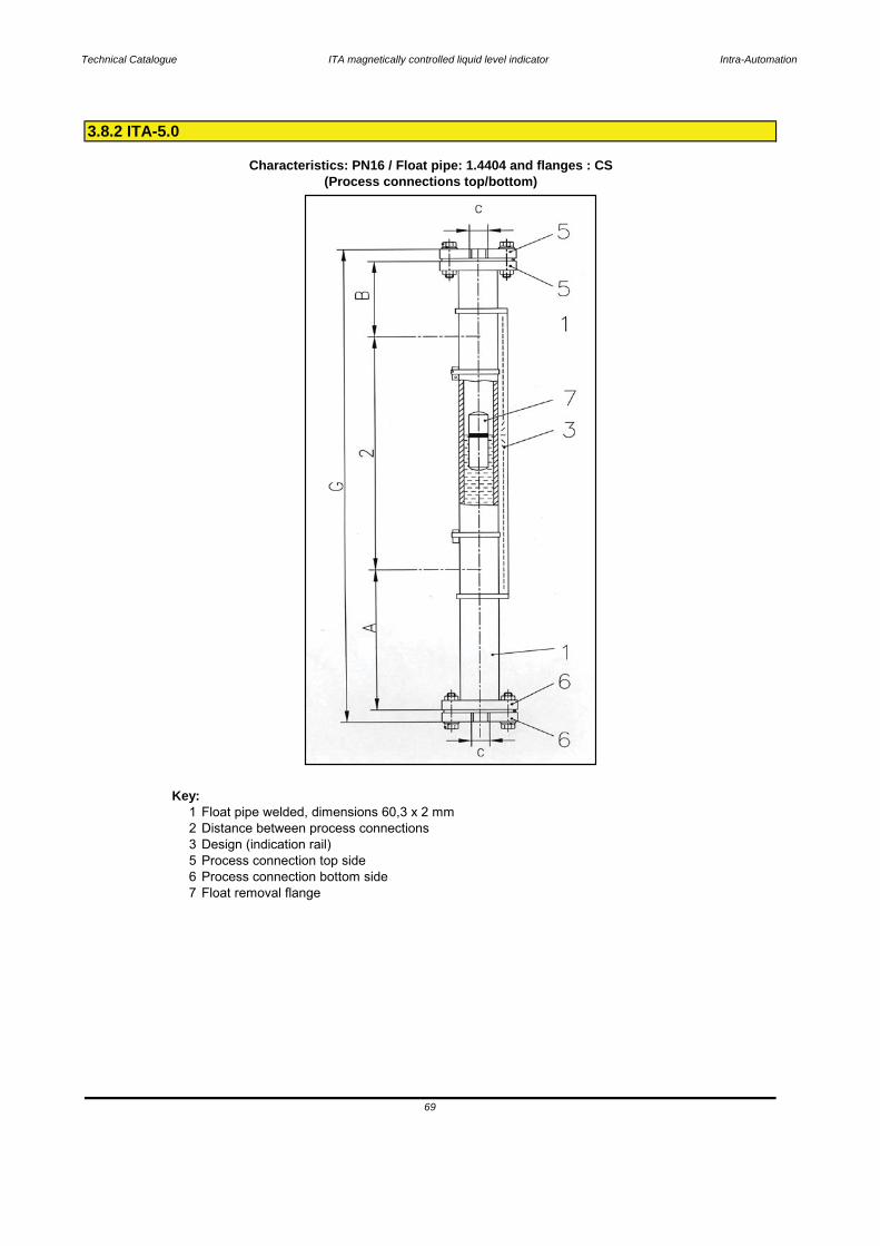
Technical Catalogue ITA magnetically controlled liquid level indicator Intra-Automation
Key:1 Float pipe welded, dimensions 60,3 x 2 mm2 Distance between process connections3 Design (indication rail)5 Process connection top side6 Process connection bottom side7 Float removal flange
Characteristics: PN16 / Float pipe: 1.4404 and flanges : CS
69
3.8.2 ITA-5.0
(Process connections top/bottom)
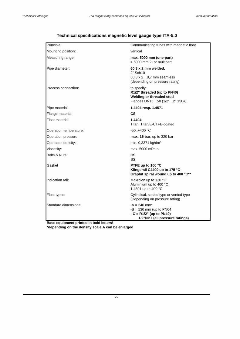
Technical Catalogue ITA magnetically controlled liquid level indicator Intra-Automation
1/2"NPT (all pressure ratings)Base equipment printed in bold letters!*depending on the density scale A can be enlarged
70
- C = R1/2" (up to PN40)
Standard dimensions: -A = 240 mm*-B = 130 mm (up to PN64
(Depending on pressure rating)Float types: Cylindical, sealed type or vented type
Aluminium up to 400 °C1.4301 up to 400 °C
Indication rail: Makrolon up to 120 °C
Klingersil C4400 up to 175 °CGraphit spiral wound up to 400 °C**
Gasket PTFE up to 100 °C
Bolts & Nuts: CSSS
Operation density: min. 0,3371 kg/dm³
Operation pressure: max. 16 bar, up to 320 bar
Operation temperature: -50..+400 °C
Titan, Titan/E-CTFE-coatedFloat material: 1.4404Flange material: CSPipe material: 1.4404 resp. 1.4571
Flanges DN15…50 (1/2"…2" 150#),
Process connection: to specify:R1/2" threaded (up to PN40)Welding or threaded stud
60,3 x 2…8,7 mm seamless(depending on pressure rating)
Pipe diameter: 60,3 x 2 mm welded,2" Sch10
> 5000 mm 2- or multipartMeasuring range: max. 5000 mm (one-part)
Mounting position: vertical
Technical specifications magnetic level gauge type ITA-5.0
Principle: Communicating tubes with magnetic float
Viscosity: max. 5000 mPa s
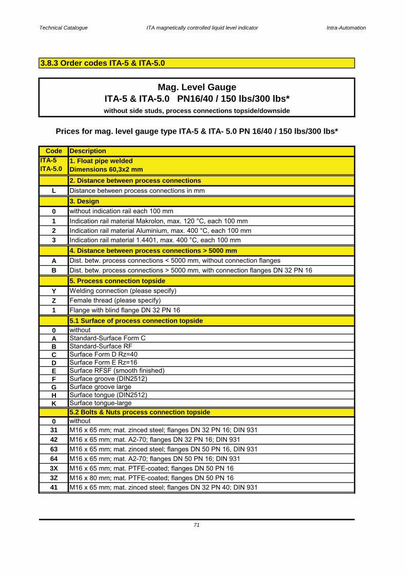
Technical Catalogue ITA magnetically controlled liquid level indicator Intra-Automation
CodeITA-5ITA-5.0
L
0123
AB
YZ1
0ABCDEFGHK
0314263643X3Z41
M16 x 65 mm; mat. PTFE-coated; flanges DN 50 PN 16M16 x 80 mm; mat. PTFE-coated; flanges DN 50 PN 16M16 x 65 mm; mat. zinced steel; flanges DN 32 PN 40; DIN 931
Surface groove largeSurface tongue (DIN2512)Surface tongue-large5.2 Bolts & Nuts process connection topsidewithoutM16 x 65 mm; mat. zinced steel; flanges DN 32 PN 16; DIN 931M16 x 65 mm; mat. A2-70; flanges DN 32 PN 16; DIN 931M16 x 65 mm; mat. zinced steel; flanges DN 50 PN 16, DIN 931M16 x 65 mm; mat. A2-70; flanges DN 50 PN 16; DIN 931
without indication rail each 100 mmIndication rail material Makrolon, max. 120 °C, each 100 mm
Surface Form D Rz=40Surface Form E Rz=16Surface RFSF (smooth finished)Surface groove (DIN2512)
withoutStandard-Surface Form CStandard-Surface RF
5.1 Surface of process connection topside
Indication rail material 1.4401, max. 400 °C, each 100 mm4. Distance between process connections > 5000 mm
Prices for mag. level gauge type ITA-5 & ITA- 5.0 PN 16/40 / 150 lbs/300 lbs*
Indication rail material Aluminium, max. 400 °C, each 100 mm
Description
Female thread (please specify)
Dist. betw. process connections < 5000 mm, without connection flangesDist. betw. process connections > 5000 mm, with connection flanges DN 32 PN 165. Process connection topside
1. Float pipe weldedDimensions 60,3x2 mm2. Distance between process connectionsDistance between process connections in mm
without side studs, process connections topside/downside
Mag. Level GaugeITA-5 & ITA-5.0 PN16/40 / 150 lbs/300 lbs*
Flange with blind flange DN 32 PN 16
3. Design
Welding connection (please specify)
3.8.3 Order codes ITA-5 & ITA-5.0
71

Technical Catalogue ITA magnetically controlled liquid level indicator Intra-Automation
Code
324344656667686X6Z
3A3B3C3D3T3VFAFBFCFDFTFV
YZA
0ABCDEFGHK
without side studs, process connections topside/downside
Surface tongue-large
Surface groove (DIN2512)
Surface Form D Rz=40Surface Form E Rz=16Surface RFSF (smooth finished)
M16 x 65 mm; mat. A2-70; flanges DN 32 PN 40; DIN 931M16 x 80 mm; mat. zinced steel; flanges DN 32 PN 40, DIN 2510M16 x 80 mm; mat. A2-70; flanges DN 32 PN 40; DIN 2510
6. Process connection bottom side
Flange with blind flange DN 50 PN 16
Welding connection (please specify)Female thread (please specify)
M16 x 65 mm; mat. PTFE-coated; flanges DN 50 PN 40M16 x 80 mm; mat. PTFE-coated; flanges DN 50 PN 40
Mag. Level GaugeITA-5 & ITA-5.0 PN16/40 / 150 lbs/300 lbs*
Description
Prices for mag. level gauge type ITA-5 & ITA- 5.0 PN 16/40 / 150 lbs/300 lbs*
M16 x 80 mm; mat. zinced steel; flanges DN 50 PN 40, DIN 2510M16 x 80 mm; mat. A2-70; flanges DN 50 PN 40; DIN 2510
M16 x 65 mm; mat. zinced steel; flanges DN 50 PN 40; DIN 931M16 x 65 mm; mat. A2-70; flanges DN 50 PN 40; DIN 931
5/8 x 95 mm; RTJ; mat. A193B7/A1942H zinced steel; flange 2" 150 lbs; ANSI B 16.55/8 x 95 mm; RTJ; mat. A193B8/A1948M SS; flange 2" 150 lbs; ANSI B 16.5
5/8 x 83 mm; RF; mat. A193B7/A1942H zinced steel; flange 2" 150 lbs; ANSI B 16.55/8 x 83 mm; RF; mat. A193B8/A1948M SS; flange 2" 150 lbs; ANSI B 16.5
5/8 x 102 mm; RTJ; mat. A193B7/A1942H zinced steel; flange 2" 300 lbs; ANSI B 16.55/8 x 102 mm; RTJ; mat. A193B8/A1948M SS; flange 2" 300 lbs; ANSI B 16.55/8 x 89 mm; RF; mat. PTFE-coated; flange 2" 300 lbs; ANSI B 16.55/8 x 102 mm; RTJ; mat. PTFE-coated; flange 2" 300 lbs; ANSI B 16.5
5/8 x 83 mm; RF; mat. PTFE-coated; flange 2" 150 lbs; ANSI B 16.55/8 x 95 mm; RTJ; mat. PTFE-coated; flange 2" 150 lbs; ANSI B 16.55/8 x 89 mm; RF; mat. A193B7/A1942H zinced steel; flange 2" 300 lbs; ANSI B 16.55/8 x 89 mm; RF; mat. A193B8/A1948M SS; flange 2" 300 lbs; ANSI B 16.5
Standard-Surface RF
6.1 Surface of process connection bottom sidewithoutStandard-Surface Form C
Surface groove largeSurface tongue (DIN2512)
5.2 Bolts & Nuts process connection topside (Continuation)
72
5.2 Bolts & Nuts process connection topside (Continuation)
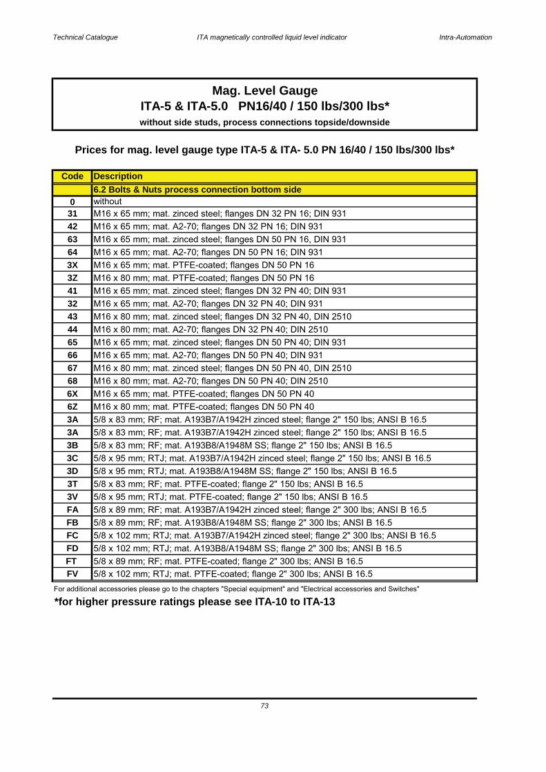
Technical Catalogue ITA magnetically controlled liquid level indicator Intra-Automation
Code
0314263643X3Z41324344656667686X6Z3A3A3B3C3D3T3VFAFBFCFDFTFV
*for higher pressure ratings please see ITA-10 to ITA-13
M16 x 65 mm; mat. A2-70; flanges DN 50 PN 40; DIN 931
5/8 x 89 mm; RF; mat. PTFE-coated; flange 2" 300 lbs; ANSI B 16.5
Mag. Level GaugeITA-5 & ITA-5.0 PN16/40 / 150 lbs/300 lbs*without side studs, process connections topside/downside
6.2 Bolts & Nuts process connection bottom side
M16 x 80 mm; mat. A2-70; flanges DN 50 PN 40; DIN 2510
M16 x 80 mm; mat. A2-70; flanges DN 32 PN 40; DIN 2510M16 x 65 mm; mat. zinced steel; flanges DN 50 PN 40; DIN 931
For additional accessories please go to the chapters "Special equipment" and "Electrical accessories and Switches"
M16 x 65 mm; mat. PTFE-coated; flanges DN 50 PN 40M16 x 80 mm; mat. PTFE-coated; flanges DN 50 PN 40
5/8 x 83 mm; RF; mat. A193B7/A1942H zinced steel; flange 2" 150 lbs; ANSI B 16.55/8 x 83 mm; RF; mat. A193B8/A1948M SS; flange 2" 150 lbs; ANSI B 16.55/8 x 95 mm; RTJ; mat. A193B7/A1942H zinced steel; flange 2" 150 lbs; ANSI B 16.55/8 x 95 mm; RTJ; mat. A193B8/A1948M SS; flange 2" 150 lbs; ANSI B 16.55/8 x 83 mm; RF; mat. PTFE-coated; flange 2" 150 lbs; ANSI B 16.5
5/8 x 102 mm; RTJ; mat. A193B8/A1948M SS; flange 2" 300 lbs; ANSI B 16.5
M16 x 80 mm; mat. zinced steel; flanges DN 50 PN 40, DIN 2510
M16 x 65 mm; mat. A2-70; flanges DN 32 PN 40; DIN 931M16 x 80 mm; mat. zinced steel; flanges DN 32 PN 40, DIN 2510
M16 x 65 mm; mat. A2-70; flanges DN 50 PN 16; DIN 931M16 x 65 mm; mat. PTFE-coated; flanges DN 50 PN 16
5/8 x 95 mm; RTJ; mat. PTFE-coated; flange 2" 150 lbs; ANSI B 16.55/8 x 89 mm; RF; mat. A193B7/A1942H zinced steel; flange 2" 300 lbs; ANSI B 16.55/8 x 89 mm; RF; mat. A193B8/A1948M SS; flange 2" 300 lbs; ANSI B 16.55/8 x 102 mm; RTJ; mat. A193B7/A1942H zinced steel; flange 2" 300 lbs; ANSI B 16.5
Prices for mag. level gauge type ITA-5 & ITA- 5.0 PN 16/40 / 150 lbs/300 lbs*
Description
M16 x 80 mm; mat. PTFE-coated; flanges DN 50 PN 16M16 x 65 mm; mat. zinced steel; flanges DN 32 PN 40; DIN 931
withoutM16 x 65 mm; mat. zinced steel; flanges DN 32 PN 16; DIN 931
73
5/8 x 83 mm; RF; mat. A193B7/A1942H zinced steel; flange 2" 150 lbs; ANSI B 16.5
M16 x 65 mm; mat. A2-70; flanges DN 32 PN 16; DIN 931M16 x 65 mm; mat. zinced steel; flanges DN 50 PN 16, DIN 931
5/8 x 102 mm; RTJ; mat. PTFE-coated; flange 2" 300 lbs; ANSI B 16.5
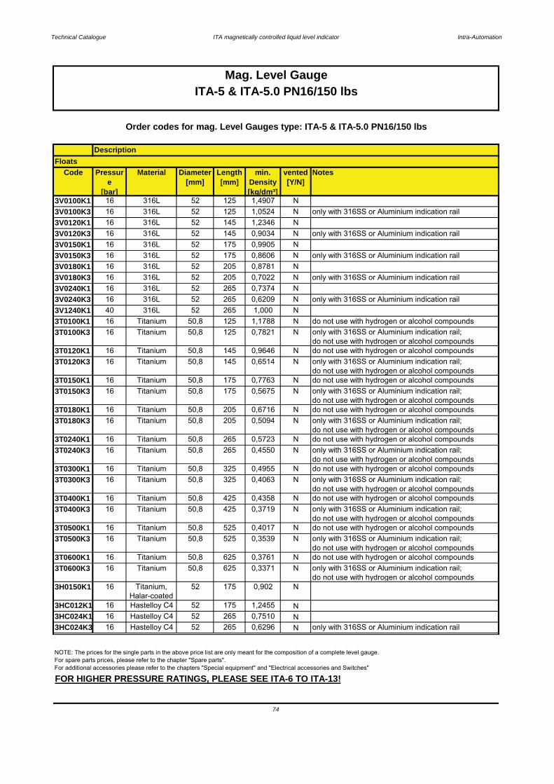
Technical Catalogue ITA magnetically controlled liquid level indicator Intra-Automation
Code Pressure
[bar]
Material Diameter[mm]
Length[mm]
min. Density[kg/dm³]
vented[Y/N]
Notes
3V0100K1 16 316L 52 125 1,4907 N3V0100K3 16 316L 52 125 1,0524 N only with 316SS or Aluminium indication rail3V0120K1 16 316L 52 145 1,2346 N3V0120K3 16 316L 52 145 0,9034 N only with 316SS or Aluminium indication rail3V0150K1 16 316L 52 175 0,9905 N3V0150K3 16 316L 52 175 0,8606 N only with 316SS or Aluminium indication rail3V0180K1 16 316L 52 205 0,8781 N3V0180K3 16 316L 52 205 0,7022 N only with 316SS or Aluminium indication rail3V0240K1 16 316L 52 265 0,7374 N3V0240K3 16 316L 52 265 0,6209 N only with 316SS or Aluminium indication rail3V1240K1 40 316L 52 265 1,000 N3T0100K1 16 Titanium 50,8 125 1,1788 N do not use with hydrogen or alcohol compounds3T0100K3 16 Titanium 50,8 125 0,7821 N only with 316SS or Aluminium indication rail;
do not use with hydrogen or alcohol compounds3T0120K1 16 Titanium 50,8 145 0,9646 N do not use with hydrogen or alcohol compounds3T0120K3 16 Titanium 50,8 145 0,6514 N only with 316SS or Aluminium indication rail;
do not use with hydrogen or alcohol compounds3T0150K1 16 Titanium 50,8 175 0,7763 N do not use with hydrogen or alcohol compounds3T0150K3 16 Titanium 50,8 175 0,5675 N only with 316SS or Aluminium indication rail;
do not use with hydrogen or alcohol compounds3T0180K1 16 Titanium 50,8 205 0,6716 N do not use with hydrogen or alcohol compounds3T0180K3 16 Titanium 50,8 205 0,5094 N only with 316SS or Aluminium indication rail;
do not use with hydrogen or alcohol compounds3T0240K1 16 Titanium 50,8 265 0,5723 N do not use with hydrogen or alcohol compounds3T0240K3 16 Titanium 50,8 265 0,4550 N only with 316SS or Aluminium indication rail;
do not use with hydrogen or alcohol compounds3T0300K1 16 Titanium 50,8 325 0,4955 N do not use with hydrogen or alcohol compounds3T0300K3 16 Titanium 50,8 325 0,4063 N only with 316SS or Aluminium indication rail;
do not use with hydrogen or alcohol compounds3T0400K1 16 Titanium 50,8 425 0,4358 N do not use with hydrogen or alcohol compounds3T0400K3 16 Titanium 50,8 425 0,3719 N only with 316SS or Aluminium indication rail;
do not use with hydrogen or alcohol compounds3T0500K1 16 Titanium 50,8 525 0,4017 N do not use with hydrogen or alcohol compounds3T0500K3 16 Titanium 50,8 525 0,3539 N only with 316SS or Aluminium indication rail;
do not use with hydrogen or alcohol compounds3T0600K1 16 Titanium 50,8 625 0,3761 N do not use with hydrogen or alcohol compounds3T0600K3 16 Titanium 50,8 625 0,3371 N only with 316SS or Aluminium indication rail;
do not use with hydrogen or alcohol compounds3H0150K1 16 Titanium,
Halar-coated52 175 0,902 N
3HC012K1 16 Hastelloy C4 52 175 1,2455 N3HC024K1 16 Hastelloy C4 52 265 0,7510 N3HC024K3 16 Hastelloy C4 52 265 0,6296 N only with 316SS or Aluminium indication rail
Mag. Level GaugeITA-5 & ITA-5.0 PN16/150 lbs
74
DescriptionFloats
NOTE: The prices for the single parts in the above price list are only meant for the composition of a complete level gauge.For spare parts prices, please refer to the chapter "Spare parts".For additional accessories please refer to the chapters "Special equipment" and "Electrical accessories and Switches"
FOR HIGHER PRESSURE RATINGS, PLEASE SEE ITA-6 TO ITA-13!
Order codes for mag. Level Gauges type: ITA-5 & ITA-5.0 PN16/150 lbs
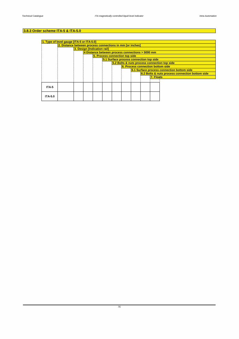
Technical Catalogue ITA magnetically controlled liquid level indicator Intra-Automation
ITA-5
ITA-5.0
75
6. Process connection bottom side6.1 Surface process connection bottom side
6.2 Bolts & nuts process connection bottom side7. Floats
4 Distance between process connections > 5000 mm5. Process connection top side
5.1 Surface process connection top side5.2 Bolts & nuts process connection top side
3.8.3 Order scheme ITA-5 & ITA-5.0
1. Type of level gauge [ITA-5 or ITA-5.0]2. Distance between process connections in mm [or inches]
3. Design [Indication rail]
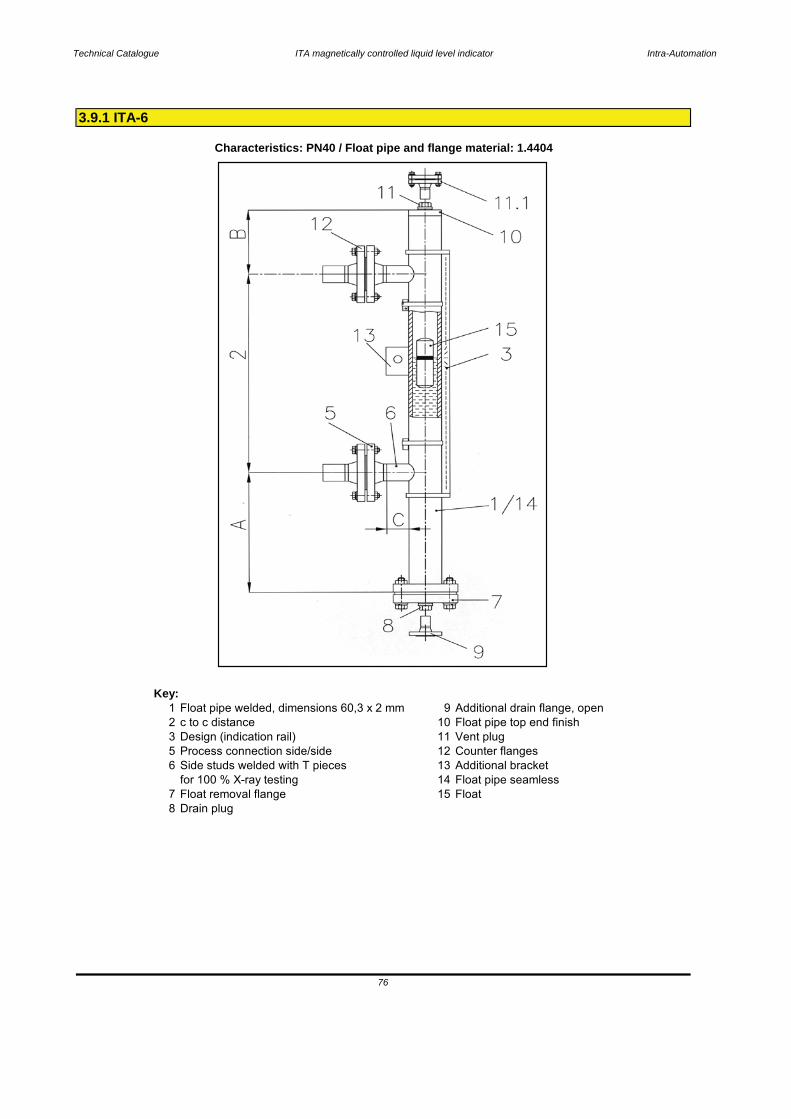
Technical Catalogue ITA magnetically controlled liquid level indicator Intra-Automation
Key:1 Float pipe welded, dimensions 60,3 x 2 mm 9 Additional drain flange, open2 c to c distance 10 Float pipe top end finish3 Design (indication rail) 11 Vent plug5 Process connection side/side 12 Counter flanges6 Side studs welded with T pieces 13 Additional bracket
for 100 % X-ray testing 14 Float pipe seamless7 Float removal flange 15 Float8 Drain plug
3.9.1 ITA-6
Characteristics: PN40 / Float pipe and flange material: 1.4404
76
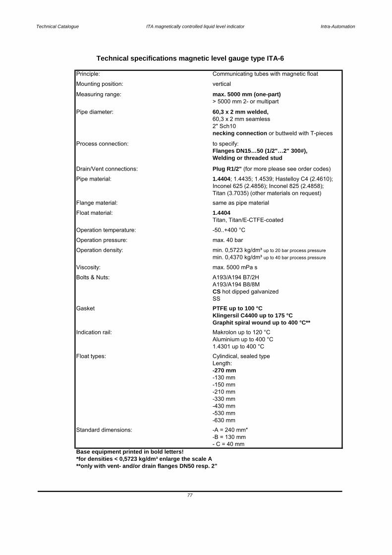
Technical Catalogue ITA magnetically controlled liquid level indicator Intra-Automation
Base equipment printed in bold letters!*for densities < 0,5723 kg/dm³ enlarge the scale A**only with vent- and/or drain flanges DN50 resp. 2"
Gasket PTFE up to 100 °C
Technical specifications magnetic level gauge type ITA-6
Principle: Communicating tubes with magnetic float
Mounting position:
Viscosity: max. 5000 mPa s
vertical
Measuring range: max. 5000 mm (one-part)
Pipe diameter: 60,3 x 2 mm welded,60,3 x 2 mm seamless
> 5000 mm 2- or multipart
Process connection: to specify:
2" Sch10necking connection or buttweld with T-pieces
Drain/Vent connections: Plug R1/2" (for more please see order codes)
Flanges DN15…50 (1/2"…2" 300#),Welding or threaded stud
Inconel 625 (2.4856); Inconel 825 (2.4858);Titan (3.7035) (other materials on request)
Pipe material: 1.4404; 1.4435; 1.4539; Hastelloy C4 (2.4610);
Float material: 1.4404Flange material: same as pipe material
Operation temperature: -50..+400 °C
Titan, Titan/E-CTFE-coated
Operation density: min. 0,5723 kg/dm³ up to 20 bar process pressure
Operation pressure: max. 40 bar
Bolts & Nuts:
CS hot dipped galvanizedSS
Indication rail: Makrolon up to 120 °C
Klingersil C4400 up to 175 °CGraphit spiral wound up to 400 °C**
Float types: Cylindical, sealed type
Aluminium up to 400 °C1.4301 up to 400 °C
-130 mm-150 mm
Length: -270 mm
-430 mm-530 mm
-210 mm-330 mm
Standard dimensions: -A = 240 mm*-B = 130 mm
-630 mm
- C = 40 mm
77
min. 0,4370 kg/dm³ up to 40 bar process pressure
A193/A194 B8/8MA193/A194 B7/2H
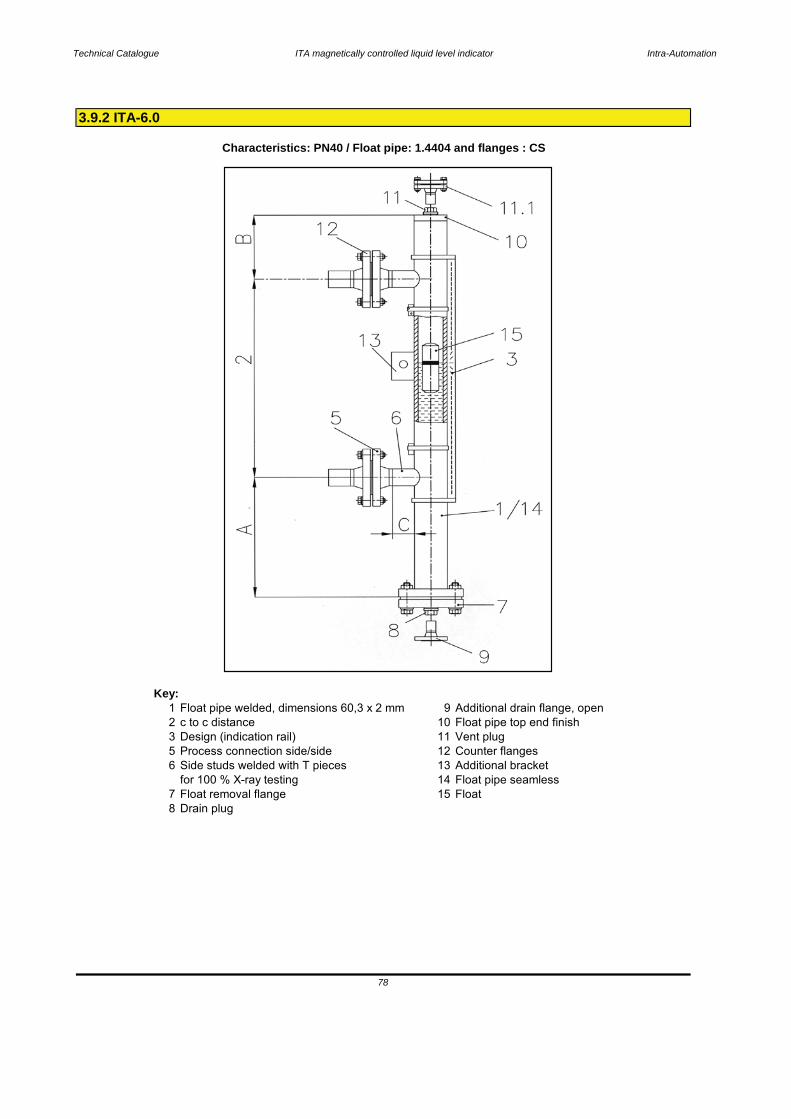
Technical Catalogue ITA magnetically controlled liquid level indicator Intra-Automation
Key:1 Float pipe welded, dimensions 60,3 x 2 mm 9 Additional drain flange, open2 c to c distance 10 Float pipe top end finish3 Design (indication rail) 11 Vent plug5 Process connection side/side 12 Counter flanges6 Side studs welded with T pieces 13 Additional bracket
for 100 % X-ray testing 14 Float pipe seamless7 Float removal flange 15 Float8 Drain plug
Characteristics: PN40 / Float pipe: 1.4404 and flanges : CS
78
3.9.2 ITA-6.0

Technical Catalogue ITA magnetically controlled liquid level indicator Intra-Automation
Base equipment printed in bold letters!*for densities < 0,5723 kg/dm³ enlarge the scale A**only with vent- and/or drain flanges DN50 resp. 2"
79
Standard dimensions: -A = 240 mm*-B = 130 mm
-630 mm
-430 mm-530 mm
-210 mm-330 mm
-130 mm-150 mm
Length: -270 mm
Float types: Cylindical, sealed type
Aluminium up to 400 °C1.4301 up to 400 °C
Indication rail: Makrolon up to 120 °C
Klingersil C4400 up to 175 °CGraphit spiral wound up to 400 °C**
Gasket PTFE up to 100 °C
CS hot dipped galvanizedSS
Bolts & Nuts: A193/A194 B7/2HA193/A194 B8/8M
Operation pressure: max. 40 bar
min. 0,4370 kg/dm³ up to 40 bar process pressure
Operation density: min. 0,5723 kg/dm³ up to 20 bar process pressure
Operation temperature: -50..+400 °C
Titan, Titan/E-CTFE-coatedFloat material: 1.4404Flange material: CSPipe material: 1.4404Drain/Vent connections: Plug R1/2" (for more please see order codes)
Flanges DN15…50 (1/2"…2" 300#),Welding or threaded stud
Process connection: to specify:
2" Sch10necking connection or buttweld with T-pieces
Pipe diameter: 60,3 x 2 mm welded,60,3 x 2 mm seamless
> 5000 mm 2- or multipartMeasuring range: max. 5000 mm (one-part)
Mounting position: vertical
Technical specifications magnetic level gauge type ITA-6.0
Principle: Communicating tubes with magnetic float
Viscosity: max. 5000 mPa s
- C = 40 mm

3.9.3 Pressure-Temperature Table ITA-6 (Float pipe)
80

Technical Catalogue ITA magnetically controlled liquid level indicator Intra-Automation
Code Description
6. Side studs welded with T-pieces for 100 % X-ray testing0 withoutT T-pieces
K Surface tongue-largeL Surface RTJ (ANSI) 1/2" bis 2"
G Surface groove largeH Surface Feder (DIN2512)
E Surface RFSF (smooth finished)F Surface Nut (DIN2512)
C Surface Form D Rz=40D Surface Form E Rz=16
A Standard- Surface Form CB Standard-Surface RF
5.1 Surface side flanges0 without
E Flanges 1 1/2" ANSI 300 lbsF Flanges 2" ANSI 300 lbs
C Flanges 1" ANSI 300 lbsD Flanges 1 1/4" ANSI 300 lbs
A Flanges 1/2" ANSI 300 lbsB Flanges 3/4" ANSI 300 lbs
5 Flanges DN 40 PN 406 Flanges DN 50 PN 40
3 Flanges DN 25 PN 404 Flanges DN 32 PN 40
1 Flanges DN 15 PN 402 Flanges DN 20 PN 40
Z Threaded connection (please specify)
B > 5000 mm - with flange connection; DN 32 PN 405. Process connection side/side
Y Welding connection (please specify)
4. c to c distance < 5000 mmA < 5000 mm - without flange connection; DN 32 PN 40
2 Indication rail material: Aluminium max. 400 °C, pro 100 mm3 Indication rail material: 1.4401 max. 400 °C, pro 100 mm
3.9.4 Order codes ITA-6 & ITA-6.0
Mag. Level GaugeITA-6 & ITA-6.0 PN40/300 lbs
1 Indication rail material: Makrolon max. 120 °C; each 100 mm0 without indication rail each 100 mm
Order codes for mag. level gauge type ITA-6 & ITA-6.0 PN40/300 lbs
L c to c distance in mm
ITA-6ITA-6.0
1. Float pipe weldedDimensions 60,3 x 2 mm2. c to c distance
3. Design
81
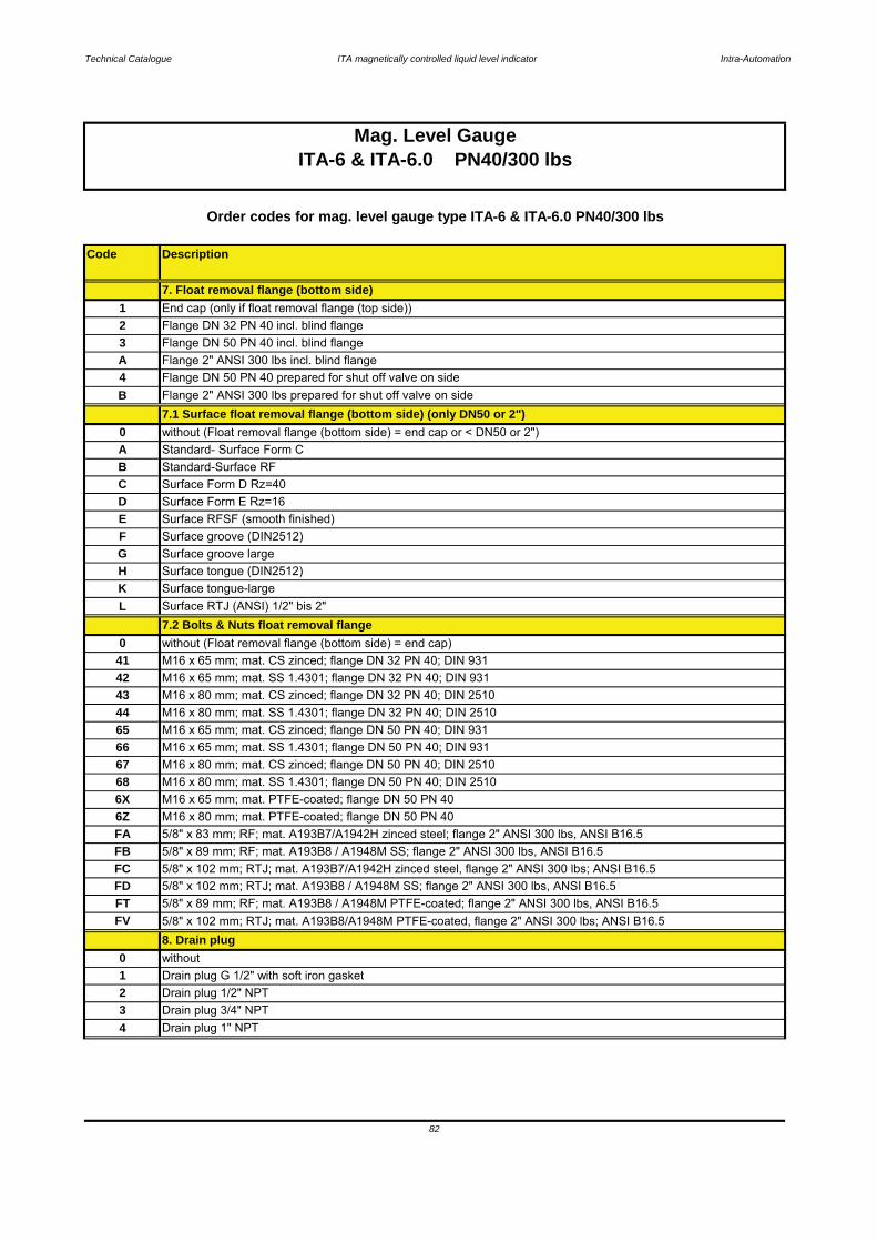
Technical Catalogue ITA magnetically controlled liquid level indicator Intra-Automation
Code Description
2 Flange DN 32 PN 40 incl. blind flangeEnd cap (only if float removal flange (top side))
3 Drain plug 3/4" NPT4 Drain plug 1" NPT
2 Drain plug 1/2" NPT
8. Drain plug0 without
FB 5/8" x 89 mm; RF; mat. A193B8 / A1948M SS; flange 2" ANSI 300 lbs, ANSI B16.5FC 5/8" x 102 mm; RTJ; mat. A193B7/A1942H zinced steel, flange 2" ANSI 300 lbs; ANSI B16.5
1 Drain plug G 1/2" with soft iron gasket
FD 5/8" x 102 mm; RTJ; mat. A193B8 / A1948M SS; flange 2" ANSI 300 lbs, ANSI B16.5
FV 5/8" x 102 mm; RTJ; mat. A193B8/A1948M PTFE-coated, flange 2" ANSI 300 lbs; ANSI B16.5FT 5/8" x 89 mm; RF; mat. A193B8 / A1948M PTFE-coated; flange 2" ANSI 300 lbs, ANSI B16.5
42 M16 x 65 mm; mat. SS 1.4301; flange DN 32 PN 40; DIN 931
65 M16 x 65 mm; mat. CS zinced; flange DN 50 PN 40; DIN 931
43 M16 x 80 mm; mat. CS zinced; flange DN 32 PN 40; DIN 251044 M16 x 80 mm; mat. SS 1.4301; flange DN 32 PN 40; DIN 2510
FA 5/8" x 83 mm; RF; mat. A193B7/A1942H zinced steel; flange 2" ANSI 300 lbs, ANSI B16.5
68 M16 x 80 mm; mat. SS 1.4301; flange DN 50 PN 40; DIN 25106X M16 x 65 mm; mat. PTFE-coated; flange DN 50 PN 406Z M16 x 80 mm; mat. PTFE-coated; flange DN 50 PN 40
0 without (Float removal flange (bottom side) = end cap)41 M16 x 65 mm; mat. CS zinced; flange DN 32 PN 40; DIN 931
L Surface RTJ (ANSI) 1/2" bis 2"7.2 Bolts & Nuts float removal flange
Standard- Surface Form C
C Surface Form D Rz=40
Surface groove (DIN2512)
K Surface tongue-large
G Surface groove largeH Surface tongue (DIN2512)
D
B Standard-Surface RF
0 without (Float removal flange (bottom side) = end cap or < DN50 or 2")
FE Surface RFSF (smooth finished)
Surface Form E Rz=16
A
4 Flange DN 50 PN 40 prepared for shut off valve on side
7.1 Surface float removal flange (bottom side) (only DN50 or 2")B Flange 2" ANSI 300 lbs prepared for shut off valve on side
A Flange 2" ANSI 300 lbs incl. blind flange3 Flange DN 50 PN 40 incl. blind flange
Order codes for mag. level gauge type ITA-6 & ITA-6.0 PN40/300 lbs
17. Float removal flange (bottom side)
Mag. Level GaugeITA-6 & ITA-6.0 PN40/300 lbs
67 M16 x 80 mm; mat. CS zinced; flange DN 50 PN 40; DIN 251066 M16 x 65 mm; mat. SS 1.4301; flange DN 50 PN 40; DIN 931
82
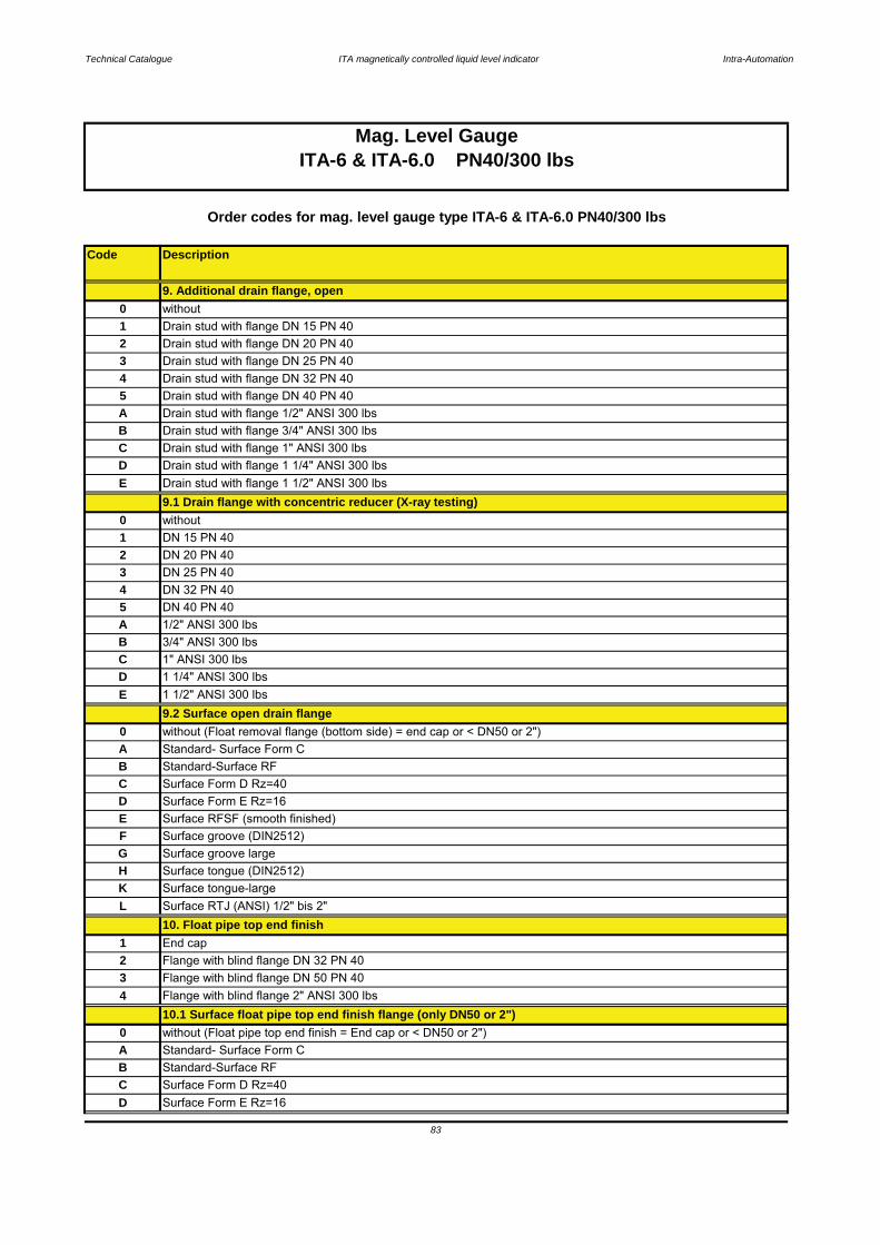
Technical Catalogue ITA magnetically controlled liquid level indicator Intra-Automation
Code Description
DN 32 PN 405
1 1/4" ANSI 300 lbs
3
A 1/2" ANSI 300 lbs
1" ANSI 300 lbs
ITA-6 & ITA-6.0 PN40/300 lbsMag. Level Gauge
B 3/4" ANSI 300 lbsC
1
D
3 Flange with blind flange DN 50 PN 404 Flange with blind flange 2" ANSI 300 lbs
1 End cap2 Flange with blind flange DN 32 PN 40
L Surface RTJ (ANSI) 1/2" bis 2"10. Float pipe top end finish
H Surface tongue (DIN2512)K Surface tongue-large
F Surface groove (DIN2512)G Surface groove large
E Surface RFSF (smooth finished)
B Standard-Surface RFC Surface Form D Rz=40D Surface Form E Rz=16
Drain stud with flange 1" ANSI 300 lbs
DN 15 PN 40
D
0 without (Float removal flange (bottom side) = end cap or < DN50 or 2")A Standard- Surface Form C
DN 25 PN 40
9.2 Surface open drain flange
9.1 Drain flange with concentric reducer (X-ray testing)0 without
E 1 1/2" ANSI 300 lbs
DN 40 PN 40
2 DN 20 PN 40
4
5 Drain stud with flange DN 40 PN 40A Drain stud with flange 1/2" ANSI 300 lbs
E Drain stud with flange 1 1/2" ANSI 300 lbsDrain stud with flange 1 1/4" ANSI 300 lbs
B Drain stud with flange 3/4" ANSI 300 lbsC
3 Drain stud with flange DN 25 PN 404 Drain stud with flange DN 32 PN 40
1 Drain stud with flange DN 15 PN 402 Drain stud with flange DN 20 PN 40
9. Additional drain flange, open0 without
Order codes for mag. level gauge type ITA-6 & ITA-6.0 PN40/300 lbs
83
Surface Form D Rz=40
10.1 Surface float pipe top end finish flange (only DN50 or 2")0 without (Float pipe top end finish = End cap or < DN50 or 2")A Standard- Surface Form CB Standard-Surface RFCD Surface Form E Rz=16
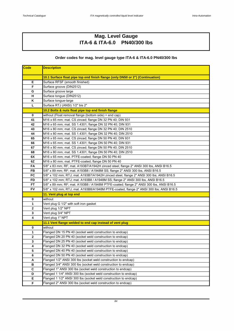
Technical Catalogue ITA magnetically controlled liquid level indicator Intra-Automation
Code Description
K Surface tongue-large
2 Vent plug 1/2" NPT
L Surface RTJ (ANSI) 1/2" bis 2"10.2 Bolts & nuts float pipe top end finish flange
42 M16 x 65 mm; mat. SS 1.4301; flange DN 32 PN 40; DIN 931
3 Vent plug 3/4" NPT
F Flanged 2" ANSI 300 lbs (socket weld construction to endcap)
Flanged DN 40 PN 40 (socket weld construction to endcap)6 Flanged DN 50 PN 40 (socket weld construction to endcap)
C Flanged 1" ANSI 300 lbs (socket weld construction to endcap)
11.1 Vent flange welded to end cap instead of vent plug
1without0Flanged DN 15 PN 40 (socket weld construction to endcap)
A Flanged 1/2" ANSI 300 lbs (socket weld construction to endcap)
4 Flanged DN 32 PN 40 (socket weld construction to endcap)5
0 without1 Vent plug G 1/2" with soft iron gasket
2
43 M16 x 80 mm; mat. CS zinced; flange DN 32 PN 40; DIN 2510
0 without (Float removal flange (bottom side) = end cap)41 M16 x 65 mm; mat. CS zinced; flange DN 32 PN 40; DIN 931
G Surface groove largeH Surface tongue (DIN2512)
E Surface RFSF (smooth finished)F Surface groove (DIN2512)
10.1 Surface float pipe top end finish flange (only DN50 or 2") (Continuation)
Order codes for mag. level gauge type ITA-6 & ITA-6.0 PN40/300 lbs
Mag. Level GaugeITA-6 & ITA-6.0 PN40/300 lbs
M16 x 65 mm; mat. PTFE-coated; flange DN 50 PN 406Z
Flanged DN 20 PN 40 (socket weld construction to endcap)
4 Vent plug 1" NPT
65 M16 x 65 mm; mat. CS zinced; flange DN 50 PN 40; DIN 93166
11. Vent plug at top end
M16 x 65 mm; mat. SS 1.4301; flange DN 50 PN 40; DIN 93167
6XM16 x 80 mm; mat. PTFE-coated; flange DN 50 PN 40
FA 5/8" x 83 mm; RF; mat. A193B7/A1942H zinced steel; flange 2" ANSI 300 lbs, ANSI B16.5FB 5/8" x 89 mm; RF; mat. A193B8 / A1948M SS; flange 2" ANSI 300 lbs, ANSI B16.5
44 M16 x 80 mm; mat. SS 1.4301; flange DN 32 PN 40; DIN 2510
M16 x 80 mm; mat. CS zinced; flange DN 50 PN 40; DIN 251068 M16 x 80 mm; mat. SS 1.4301; flange DN 50 PN 40; DIN 2510
3 Flanged DN 25 PN 40 (socket weld construction to endcap)
D Flanged 1 1/4" ANSI 300 lbs (socket weld construction to endcap)E Flanged 1 1/2" ANSI 300 lbs (socket weld construction to endcap)
B Flanged 3/4" ANSI 300 lbs (socket weld construction to endcap)
84
FV 5/8" x 102 mm; RTJ; mat. A193B8/A1948M PTFE-coated, flange 2" ANSI 300 lbs; ANSI B16.5
FC 5/8" x 102 mm; RTJ; mat. A193B7/A1942H zinced steel, flange 2" ANSI 300 lbs; ANSI B16.5FD 5/8" x 102 mm; RTJ; mat. A193B8 / A1948M SS; flange 2" ANSI 300 lbs, ANSI B16.5FT 5/8" x 89 mm; RF; mat. A193B8 / A1948M PTFE-coated; flange 2" ANSI 300 lbs, ANSI B16.5
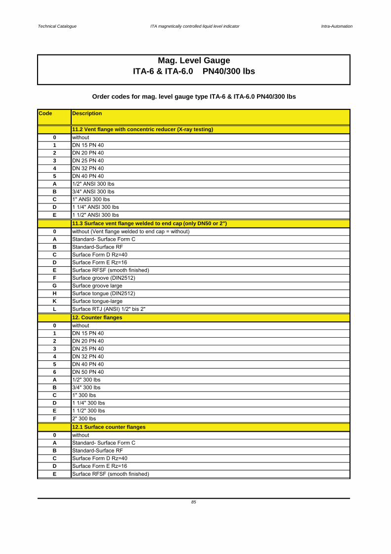
Technical Catalogue ITA magnetically controlled liquid level indicator Intra-Automation
Code Description
E Surface RFSF (smooth finished)D Surface Form E Rz=16
A Standard- Surface Form C
C Surface Form D Rz=40B Standard-Surface RF
E 1 1/2" 300 lbsD 1 1/4" 300 lbs
A 1/2" 300 lbs
C 1" 300 lbs
2 DN 20 PN 403 DN 25 PN 40
0 without12.1 Surface counter flanges
F 2" 300 lbs
DN 50 PN 40
B 3/4" 300 lbs
4 DN 32 PN 405 DN 40 PN 406
0 without1 DN 15 PN 40
L Surface RTJ (ANSI) 1/2" bis 2"12. Counter flanges
H Surface tongue (DIN2512)K Surface tongue-large
F Surface groove (DIN2512)G Surface groove large
D Surface Form E Rz=16E Surface RFSF (smooth finished)
B Standard-Surface RFC Surface Form D Rz=40
0 without (Vent flange welded to end cap = without)A Standard- Surface Form C
E 1 1/2" ANSI 300 lbs11.3 Surface vent flange welded to end cap (only DN50 or 2")
C 1" ANSI 300 lbsD 1 1/4" ANSI 300 lbs
A 1/2" ANSI 300 lbsB 3/4" ANSI 300 lbs
4 DN 32 PN 405 DN 40 PN 40
2 DN 20 PN 403 DN 25 PN 40
1 DN 15 PN 40
11.2 Vent flange with concentric reducer (X-ray testing)
Mag. Level GaugeITA-6 & ITA-6.0 PN40/300 lbs
Order codes for mag. level gauge type ITA-6 & ITA-6.0 PN40/300 lbs
0 without
85
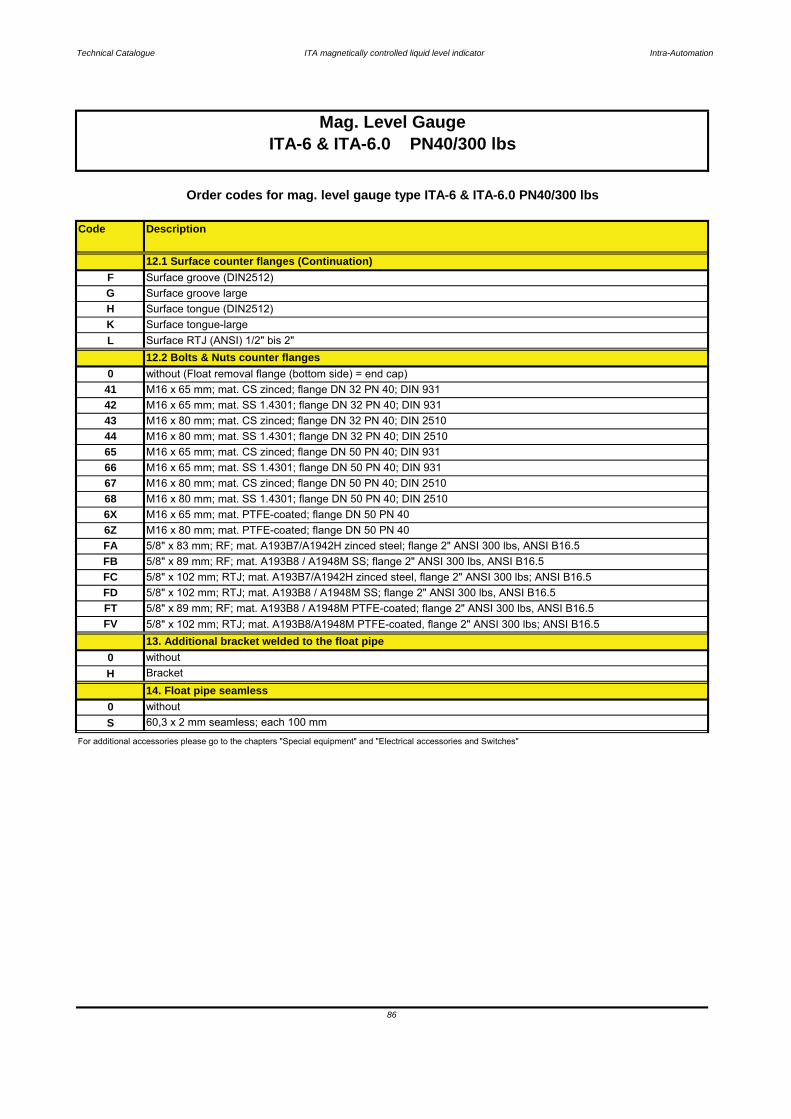
Technical Catalogue ITA magnetically controlled liquid level indicator Intra-Automation
Code Description
F Surface groove (DIN2512)
Surface tongue (DIN2512)
Order codes for mag. level gauge type ITA-6 & ITA-6.0 PN40/300 lbs
12.1 Surface counter flanges (Continuation)
60,3 x 2 mm seamless; each 100 mm0 without
12.2 Bolts & Nuts counter flanges
FV 5/8" x 102 mm; RTJ; mat. A193B8/A1948M PTFE-coated, flange 2" ANSI 300 lbs; ANSI B16.5
FD 5/8" x 102 mm; RTJ; mat. A193B8 / A1948M SS; flange 2" ANSI 300 lbs, ANSI B16.5FT
For additional accessories please go to the chapters "Special equipment" and "Electrical accessories and Switches"
Bracket
13. Additional bracket welded to the float pipe0 without
14. Float pipe seamlessH
S
Surface tongue-largeSurface RTJ (ANSI) 1/2" bis 2"
HG Surface groove large
KL
5/8" x 89 mm; RF; mat. A193B8 / A1948M PTFE-coated; flange 2" ANSI 300 lbs, ANSI B16.5
FB 5/8" x 89 mm; RF; mat. A193B8 / A1948M SS; flange 2" ANSI 300 lbs, ANSI B16.5FC 5/8" x 102 mm; RTJ; mat. A193B7/A1942H zinced steel, flange 2" ANSI 300 lbs; ANSI B16.5
6Z M16 x 80 mm; mat. PTFE-coated; flange DN 50 PN 40
66 M16 x 65 mm; mat. SS 1.4301; flange DN 50 PN 40; DIN 93167 M16 x 80 mm; mat. CS zinced; flange DN 50 PN 40; DIN 2510
44 M16 x 80 mm; mat. SS 1.4301; flange DN 32 PN 40; DIN 251065 M16 x 65 mm; mat. CS zinced; flange DN 50 PN 40; DIN 931
FA 5/8" x 83 mm; RF; mat. A193B7/A1942H zinced steel; flange 2" ANSI 300 lbs, ANSI B16.5
68 M16 x 80 mm; mat. SS 1.4301; flange DN 50 PN 40; DIN 25106X M16 x 65 mm; mat. PTFE-coated; flange DN 50 PN 40
42 M16 x 65 mm; mat. SS 1.4301; flange DN 32 PN 40; DIN 93143 M16 x 80 mm; mat. CS zinced; flange DN 32 PN 40; DIN 2510
41 M16 x 65 mm; mat. CS zinced; flange DN 32 PN 40; DIN 9310 without (Float removal flange (bottom side) = end cap)
Mag. Level GaugeITA-6 & ITA-6.0 PN40/300 lbs
86
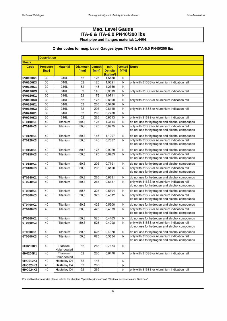
Technical Catalogue ITA magnetically controlled liquid level indicator Intra-Automation
Code Pressure[bar]
Material Diameter[mm]
Length[mm]
min. Density[kg/dm³]
vented[Y/N]
Notes
6V0100K1 30 316L 52 125 1,5188 N6V0100K3 30 316L 52 125 1,0891 N only with 316SS or Aluminium indication rail6V0120K1 30 316L 52 145 1,2780 N6V0120K3 30 316L 52 145 0,9519 N only with 316SS or Aluminium indication rail6V0150K1 30 316L 52 175 1,0711 N6V0150K3 30 316L 52 175 0,8309 N only with 316SS or Aluminium indication rail6V0180K1 30 316L 52 205 0,9486 N6V0180K3 30 316L 52 205 0,8140 N only with 316SS or Aluminium indication rail6V0240K1 30 316L 52 265 0,7738 N6V0240K3 30 316L 52 265 0,6513 N only with 316SS or Aluminium indication rail6T0100K1 40 Titanium 50,8 125 1,3114 N do not use for hydrogen and alcohol compounds6T0100K3 40 Titanium 50,8 125 0,8975 N only with 316SS or Aluminium indication rail
do not use for hydrogen and alcohol compounds
6T0120K1 40 Titanium 50,8 145 1,1007 N do not use for hydrogen and alcohol compounds6T0120K3 40 Titanium 50,8 145 0,7837 N only with 316SS or Aluminium indication rail
do not use for hydrogen and alcohol compounds
6T0150K1 40 Titanium 50,8 175 0,9029 N do not use for hydrogen and alcohol compounds6T0150K3 40 Titanium 50,8 175 0,6763 N only with 316SS or Aluminium indication rail
do not use for hydrogen and alcohol compounds
6T0180K1 40 Titanium 50,8 205 0,7791 N do not use for hydrogen and alcohol compounds6T0180K3 40 Titanium 50,8 205 0,6100 N only with 316SS or Aluminium indication rail
do not use for hydrogen and alcohol compounds
6T0240K1 40 Titanium 50,8 265 0,6391 N do not use for hydrogen and alcohol compounds6T0240K3 40 Titanium 50,8 265 0,5187 N only with 316SS or Aluminium indication rail
do not use for hydrogen and alcohol compounds
6T0300K1 40 Titanium 50,8 325 0,5694 N do not use for hydrogen and alcohol compounds6T0300K3 40 Titanium 50,8 325 0,4812 N only with 316SS or Aluminium indication rail
do not use for hydrogen and alcohol compounds
6T0400K1 40 Titanium 50,8 425 0,5300 N do not use for hydrogen and alcohol compounds6T0400K3 40 Titanium 50,8 425 0,4373 N only with 316SS or Aluminium indication rail
do not use for hydrogen and alcohol compounds
6T0500K1 40 Titanium 50,8 525 0,4463 N do not use for hydrogen and alcohol compounds6T0500K3 40 Titanium 50,8 525 0,4098 N only with 316SS or Aluminium indication rail
do not use for hydrogen and alcohol compounds
6T0600K1 40 Titanium 50,8 625 0,4370 N do not use for hydrogen and alcohol compounds6T0600K3 40 Titanium 50,8 625 0,3834 N only with 316SS or Aluminium indication rail
do not use for hydrogen and alcohol compounds
6H0200K1 40 Titanium,Halar-coated
52 265 0,7674 N
6H0200K1 40 Titanium,Halar-coated
52 265 0,6470 N only with 316SS or Aluminium indication rail
6HC012K1 40 Hastelloy C4 52 145 N6HC024K1 40 Hastelloy C4 52 265 N6HC024K3 40 Hastelloy C4 52 265 N only with 316SS or Aluminium indication rail
87
Mag. Level GaugeITA-6 & ITA-6.0 PN40/300 lbsFloat pipe and flanges material: 1.4404
For additional accessories please refer to the chapters "Special equipment" and "Electrical accessories and Switches"
Order codes for mag. Level Gauges type: ITA-6 & ITA-6.0 PN40/300 lbs
DescriptionFloats
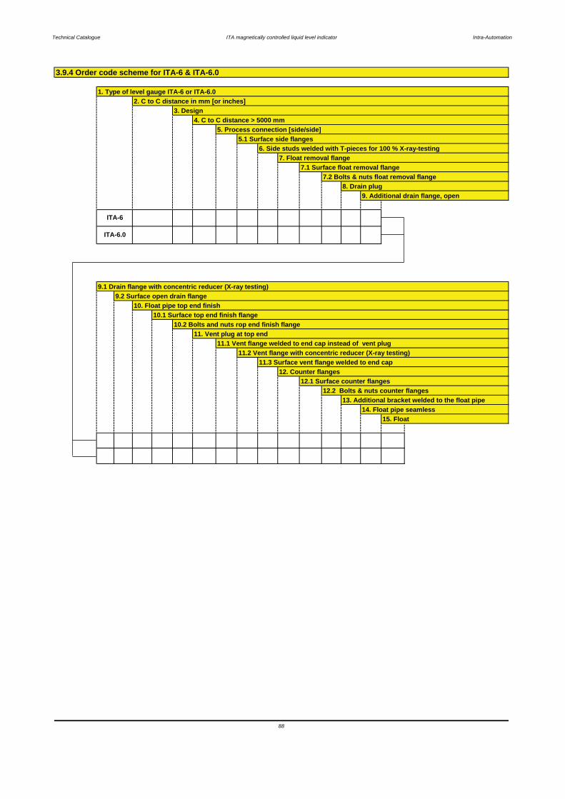
Technical Catalogue ITA magnetically controlled liquid level indicator Intra-Automation
3.9.4 Order code scheme for ITA-6 & ITA-6.0
1. Type of level gauge ITA-6 or ITA-6.02. C to C distance in mm [or inches]
3. Design4. C to C distance > 5000 mm
5. Process connection [side/side]5.1 Surface side flanges
6. Side studs welded with T-pieces for 100 % X-ray-testing7. Float removal flange
7.1 Surface float removal flange7.2 Bolts & nuts float removal flange
8. Drain plug9. Additional drain flange, open
ITA-6.0
9.1 Drain flange with concentric reducer (X-ray testing)9.2 Surface open drain flange
ITA-6
11.1 Vent flange welded to end cap instead of vent plug11.2 Vent flange with concentric reducer (X-ray testing)
11.3 Surface vent flange welded to end cap 12. Counter flanges
10. Float pipe top end finish10.1 Surface top end finish flange
10.2 Bolts and nuts rop end finish flange11. Vent plug at top end
88
15. Float
12.1 Surface counter flanges12.2 Bolts & nuts counter flanges
13. Additional bracket welded to the float pipe14. Float pipe seamless
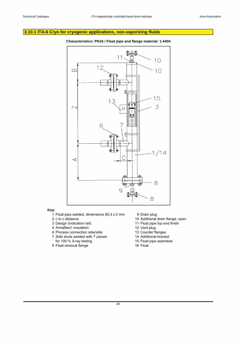
Technical Catalogue ITA magnetically controlled liquid level indicator Intra-Automation
Key:1 Float pipe welded, dimensions 60,3 x 2 mm 9 Drain plug2 c to c distance 10 Additional drain flange, open3 Design (indication rail) 11 Float pipe top end finish4 Armaflex insulation 12 Vent plug6 Process connection side/side 13 Counter flanges7 Side studs welded with T pieces 14 Additional bracket
for 100 % X-ray testing 15 Float pipe seamless8 Float removal flange 16 Float
3.10.1 ITA-6 Cryo for cryogenic applications, non-vaporizing fluids
Characteristics: PN16 / Float pipe and flange material: 1.4404
89
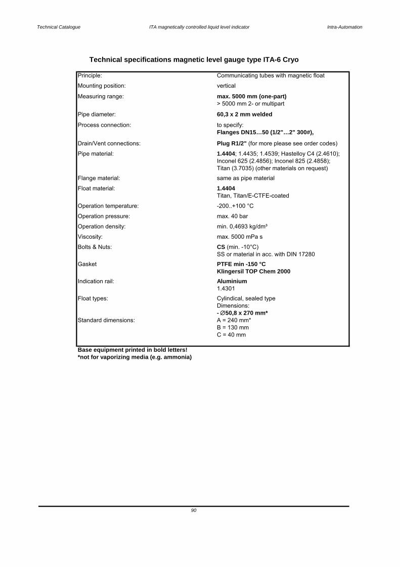
Technical Catalogue ITA magnetically controlled liquid level indicator Intra-Automation
Base equipment printed in bold letters!*not for vaporizing media (e.g. ammonia)
Technical specifications magnetic level gauge type ITA-6 Cryo
Mounting position: vertical
Principle: Communicating tubes with magnetic float
Pipe diameter: 60,3 x 2 mm welded
Measuring range: max. 5000 mm (one-part)> 5000 mm 2- or multipart
Process connection: to specify:Flanges DN15…50 (1/2"…2" 300#),
Drain/Vent connections: Plug R1/2" (for more please see order codes)
Titan (3.7035) (other materials on request)
Pipe material: 1.4404; 1.4435; 1.4539; Hastelloy C4 (2.4610); Inconel 625 (2.4856); Inconel 825 (2.4858);
Float material: 1.4404Titan, Titan/E-CTFE-coated
Flange material: same as pipe material
Operation pressure: max. 40 bar
Operation temperature: -200..+100 °C
Operation density: min. 0,4693 kg/dm³
SS or material in acc. with DIN 17280Bolts & Nuts: CS (min. -10°C)
Viscosity: max. 5000 mPa s
Indication rail: Aluminium
Gasket PTFE min -150 °CKlingersil TOP Chem 2000
C = 40 mm
Float types: Cylindical, sealed typeDimensions:
1.4301
- 50,8 x 270 mm*
90
Standard dimensions: A = 240 mm*B = 130 mm
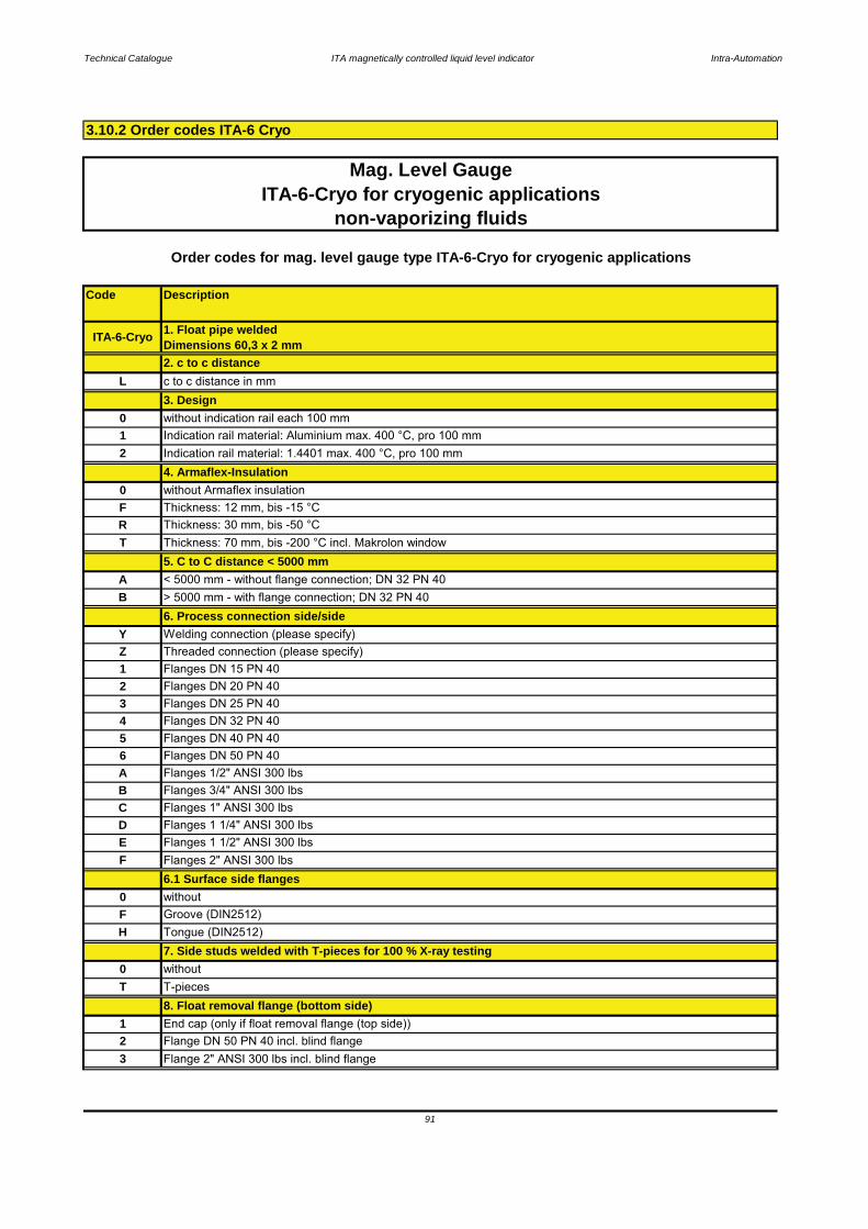
Technical Catalogue ITA magnetically controlled liquid level indicator Intra-Automation
Code Description
Mag. Level GaugeITA-6-Cryo for cryogenic applications
non-vaporizing fluids
H Tongue (DIN2512)
3 Flange 2" ANSI 300 lbs incl. blind flange2 Flange DN 50 PN 40 incl. blind flange1
0T T-pieces
8. Float removal flange (bottom side)
7. Side studs welded with T-pieces for 100 % X-ray testing
End cap (only if float removal flange (top side))
without
D
Groove (DIN2512)F
6.1 Surface side flanges0 without
Flanges 1 1/4" ANSI 300 lbs
F Flanges 2" ANSI 300 lbs
Flanges DN 50 PN 40A Flanges 1/2" ANSI 300 lbsB Flanges 3/4" ANSI 300 lbsC Flanges 1" ANSI 300 lbs
Flanges DN 15 PN 40
3 Flanges DN 25 PN 40
E Flanges 1 1/2" ANSI 300 lbs
4 Flanges DN 32 PN 405 Flanges DN 40 PN 406
Thickness: 12 mm, bis -15 °CR Thickness: 30 mm, bis -50 °CT Thickness: 70 mm, bis -200 °C incl. Makrolon window
5. C to C distance < 5000 mm
2 Flanges DN 20 PN 40
Z Threaded connection (please specify)
B > 5000 mm - with flange connection; DN 32 PN 406. Process connection side/side
Y Welding connection (please specify)
1
2. c to c distance
ITA-6-Cryo
Order codes for mag. level gauge type ITA-6-Cryo for cryogenic applications
1. Float pipe weldedDimensions 60,3 x 2 mm
A < 5000 mm - without flange connection; DN 32 PN 40
4. Armaflex-Insulation0 without Armaflex insulationF
L c to c distance in mm3. Design
2 Indication rail material: 1.4401 max. 400 °C, pro 100 mm
0 without indication rail each 100 mm1 Indication rail material: Aluminium max. 400 °C, pro 100 mm
3.10.2 Order codes ITA-6 Cryo
91

Technical Catalogue ITA magnetically controlled liquid level indicator Intra-Automation
Code Description
0
Mag. Level Gauge
0 without (Float pipe top end finish = End cap or < DN50 or 2")
H Tongue (DIN2512)
M16 x 65 mm; mat. SS 1.4301; flange DN 50 PN 40; DIN 93166
FC 5/8" x 102 mm; RTJ; mat. A193B7/A1942H zinced steel, flange 2" ANSI 300 lbs; ANSI B16.5
10.2 Bolts & nuts float pipe top end finish flange
F Groove (DIN2512)
01 G 1/2" DIN1910
9. Drain plugwithout
M16 x 65 mm; mat. CS zinced; flange DN 50 PN 40; DIN 931
68 M16 x 80 mm; mat. SS 1.4301; flange DN 50 PN 40; DIN 25106X
67 M16 x 80 mm; mat. CS zinced; flange DN 50 PN 40; DIN 2510
6566 M16 x 65 mm; mat. SS 1.4301; flange DN 50 PN 40; DIN 931
M16 x 65 mm; mat. PTFE-coated; flange DN 50 PN 40
H
non-vaporizing fluids
without (Float removal flange (bottom side) = end cap or < DN50 or 2")F
Order codes for mag. level gauge type ITA-6-Cryo for cryogenic applications
08.1 Surface float removal flange (bottom side) (only DN50 or 2")
without (Float removal flange (bottom side) = end cap)
Groove (DIN2512)Tongue (DIN2512)8.2 Bolts & Nuts float removal flange
ITA-6-Cryo for cryogenic applications
FD 5/8" x 102 mm; RTJ; mat. A193B8 / A1948M SS; flange 2" ANSI 300 lbs, ANSI B16.5FT 5/8" x 89 mm; RF; mat. A193B8 / A1948M PTFE-coated; flange 2" ANSI 300 lbs, ANSI B16.5
6Z M16 x 80 mm; mat. PTFE-coated; flange DN 50 PN 40FA 5/8" x 83 mm; RF; mat. A193B7/A1942H zinced steel; flange 2" ANSI 300 lbs, ANSI B16.5
5/8" x 89 mm; RF; mat. A193B8 / A1948M SS; flange 2" ANSI 300 lbs, ANSI B16.5FB
FV 5/8" x 102 mm; RTJ; mat. A193B8/A1948M PTFE-coated, flange 2" ANSI 300 lbs; ANSI B16.5
67 M16 x 80 mm; mat. CS zinced; flange DN 50 PN 40; DIN 2510
10. Float pipe top end finish
Flange with blind flange 2" ANSI 300 lbs2 Flange with blind flange DN 50 PN 401 End cap
68 M16 x 80 mm; mat. SS 1.4301; flange DN 50 PN 40; DIN 25106X M16 x 65 mm; mat. PTFE-coated; flange DN 50 PN 40
10.1 Surface float pipe top end finish flange (only DN50 or 2")A
65 M16 x 65 mm; mat. CS zinced; flange DN 50 PN 40; DIN 9310 without (Float pipe top end = end cap)
FB 5/8" x 89 mm; RF; mat. A193B8 / A1948M SS; flange 2" ANSI 300 lbs, ANSI B16.5FC 5/8" x 102 mm; RTJ; mat. A193B7/A1942H zinced steel, flange 2" ANSI 300 lbs; ANSI B16.5
6Z M16 x 80 mm; mat. PTFE-coated; flange DN 50 PN 40FA 5/8" x 83 mm; RF; mat. A193B7/A1942H zinced steel; flange 2" ANSI 300 lbs, ANSI B16.5
FD 5/8" x 102 mm; RTJ; mat. A193B8 / A1948M SS; flange 2" ANSI 300 lbs, ANSI B16.5FT 5/8" x 89 mm; RF; mat. A193B8 / A1948M PTFE-coated; flange 2" ANSI 300 lbs, ANSI B16.5FV 5/8" x 102 mm; RTJ; mat. A193B8/A1948M PTFE-coated, flange 2" ANSI 300 lbs; ANSI B16.5
10
11. Vent plug on topside
Vent plug G 1/2" with soft iron gasketwithout
92
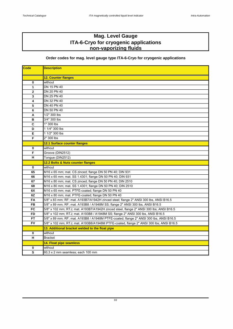
Technical Catalogue ITA magnetically controlled liquid level indicator Intra-Automation
Code Description
H Bracket
13. Additional bracket welded to the float pipe
68
FT 5/8" x 89 mm; RF; mat. A193B8 / A1948M PTFE-coated; flange 2" ANSI 300 lbs, ANSI B16.5
0 without
FC
Order codes for mag. level gauge type ITA-6-Cryo for cryogenic applications
non-vaporizing fluids
Tongue (DIN2512)
6Z6X M16 x 65 mm; mat. PTFE-coated; flange DN 50 PN 40
12.2 Bolts & Nuts counter flanges
2" 300 lbs
M16 x 65 mm; mat. SS 1.4301; flange DN 50 PN 40; DIN 931
H
M16 x 80 mm; mat. SS 1.4301; flange DN 50 PN 40; DIN 2510
F
S 60,3 x 2 mm seamless; each 100 mm
5/8" x 102 mm; RTJ; mat. A193B7/A1942H zinced steel, flange 2" ANSI 300 lbs; ANSI B16.5
14. Float pipe seamless0 without
5/8" x 89 mm; RF; mat. A193B8 / A1948M SS; flange 2" ANSI 300 lbs, ANSI B16.55/8" x 83 mm; RF; mat. A193B7/A1942H zinced steel; flange 2" ANSI 300 lbs, ANSI B16.5
1 1/2" 300 lbs
4 DN 32 PN 40
FA
12.1 Surface counter flanges
0 without
6766
without
D 1 1/4" 300 lbsE
Groove (DIN2512)
Mag. Level GaugeITA-6-Cryo for cryogenic applications
C 1" 300 lbs
F
56 DN 50 PN 40
DN 40 PN 40
M16 x 80 mm; mat. CS zinced; flange DN 50 PN 40; DIN 2510
A 1/2" 300 lbsB 3/4" 300 lbs
0
DN 25 PN 40
0 without
2 DN 20 PN 401
65 M16 x 65 mm; mat. CS zinced; flange DN 50 PN 40; DIN 931
12. Counter flanges
DN 15 PN 40
3
93
FD 5/8" x 102 mm; RTJ; mat. A193B8 / A1948M SS; flange 2" ANSI 300 lbs, ANSI B16.5
FV 5/8" x 102 mm; RTJ; mat. A193B8/A1948M PTFE-coated, flange 2" ANSI 300 lbs; ANSI B16.5
M16 x 80 mm; mat. PTFE-coated; flange DN 50 PN 40
FB
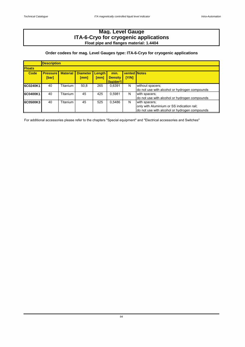
Technical Catalogue ITA magnetically controlled liquid level indicator Intra-Automation
Code Pressure[bar]
Material Diameter[mm]
Length[mm]
min. Density[kg/dm³]
vented[Y/N]
Notes
6C0240K1 40 Titanium 50,8 265 0,6391 N without spacers;do not use with alcohol or hydrogen compounds
6C0400K1 40 Titanium 45 425 0,5981 N with spacers;do not use with alcohol or hydrogen compounds
6C0500K3 40 Titanium 45 525 0,5486 N with spacers; only with Aluminium or SS indication rail;do not use with alcohol or hydrogen compounds
For additional accessories please refer to the chapters "Special equipment" and "Electrical accessories and Switches"
94
Mag. Level GaugeITA-6-Cryo for cryogenic applications
Float pipe and flanges material: 1.4404
Floats
Order codees for mag. Level Gauges type: ITA-6-Cryo for cryogenic applications
Description
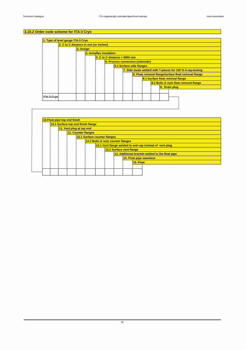
Technical Catalogue ITA magnetically controlled liquid level indicator Intra-Automation
3.10.2 Order code scheme for ITA-3 Cryo
1. Type of level gauge ITA-3 Cryo2. C to C distance in mm [or inches]
3. Design4. Armaflex insulation
5. C to C distance > 5000 mm6. Process connection [side/side]
6.1 Surface side flanges 7. Side studs welded with T-pieces for 100 % X-ray-testing
8.2 Bolts & nuts float removal flange9. Drain plug
8. Float removal flangeSurface float removal flange8.1 Surface float removal flange
ITA-3-Cryo
12.1 Surface counter flanges12.2 Bolts & nuts counter flanges
12.1 Vent flange welded to end cap instead of vent plug12.2 Surface vent flange
10.Float pipe top end finish10.1 Surface top end finish flange
11. Vent plug at top end12. Counter flanges
95
13. Additional bracket welded to the float pipe14. Float pipe seamless
15. Float

Technical Catalogue ITA magnetically controlled liquid level indicator Intra-Automation
Key:1 Float pipe welded, dimensions 64 x 2 mm 9 Drain plug2 c to c distance 10 Additional drain flange, open3 Design (indication rail) 11 Float pipe top end finish4 Armaflex insulation 12 Vent plug6 Process connection side/side 13 Counter flanges7 Side studs welded with T pieces 14 Additional bracket
for 100 % X-ray testing 15 Float pipe seamless8 Float removal flange 16 Float
3.11.1 ITA-6 CR64 for cryogenic applications, vaporizing fluid
Characteristics: PN40 / Float pipe and flange material: 1.4571
96
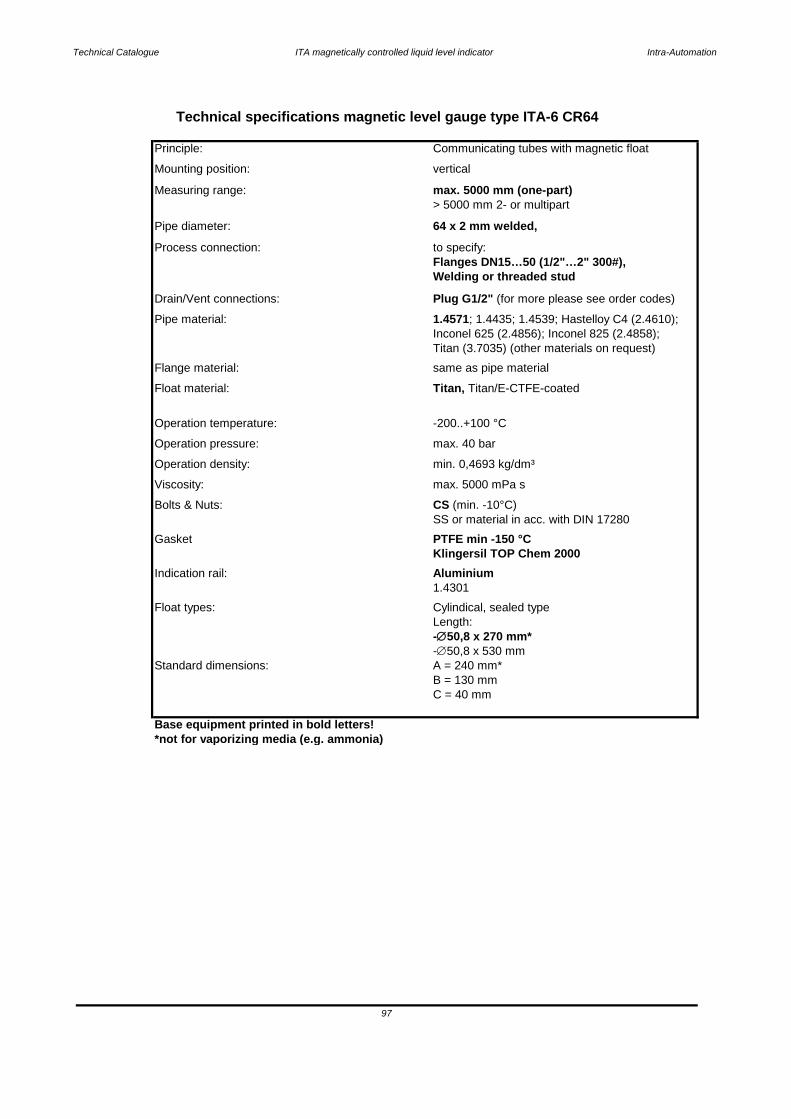
Technical Catalogue ITA magnetically controlled liquid level indicator Intra-Automation
Base equipment printed in bold letters!*not for vaporizing media (e.g. ammonia)
Viscosity: max. 5000 mPa s
Principle: Communicating tubes with magnetic float
> 5000 mm 2- or multipart
Technical specifications magnetic level gauge type ITA-6 CR64
Measuring range: max. 5000 mm (one-part)
Mounting position: vertical
Process connection: to specify:
Pipe diameter: 64 x 2 mm welded,
Drain/Vent connections: Plug G1/2" (for more please see order codes)
Flanges DN15…50 (1/2"…2" 300#),Welding or threaded stud
Inconel 625 (2.4856); Inconel 825 (2.4858);Titan (3.7035) (other materials on request)
Pipe material: 1.4571; 1.4435; 1.4539; Hastelloy C4 (2.4610);
Float material: Titan, Titan/E-CTFE-coated
Flange material: same as pipe material
Operation temperature: -200..+100 °C
Operation density: min. 0,4693 kg/dm³
Operation pressure: max. 40 bar
Gasket PTFE min -150 °C
Bolts & Nuts: CS (min. -10°C)SS or material in acc. with DIN 17280
Indication rail: Aluminium1.4301
Klingersil TOP Chem 2000
-∅50,8 x 530 mm
Float types: Cylindical, sealed typeLength: -∅50,8 x 270 mm*
97
Standard dimensions: A = 240 mm*B = 130 mmC = 40 mm
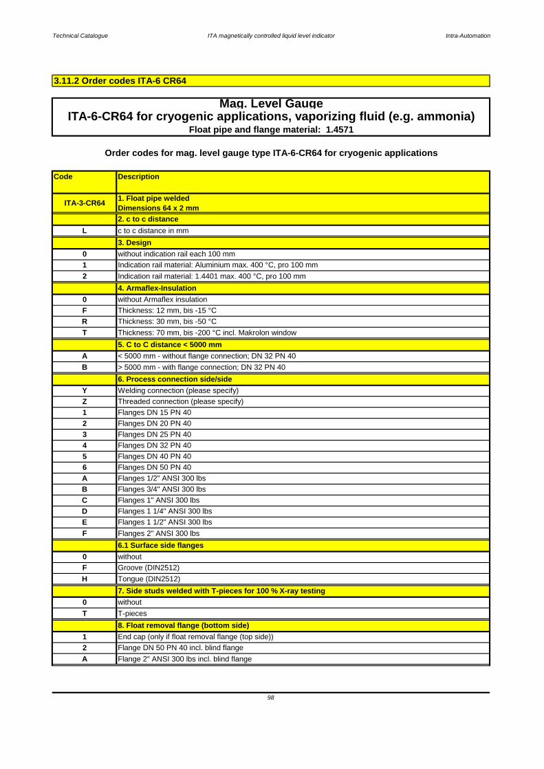
Technical Catalogue ITA magnetically controlled liquid level indicator Intra-Automation
Code Description
Mag. Level GaugeITA-6-CR64 for cryogenic applications, vaporizing fluid (e.g. ammonia)
Float pipe and flange material: 1.4571
1 End cap (only if float removal flange (top side))
0T T-pieces
8. Float removal flange (bottom side)
F
2 Flange DN 50 PN 40 incl. blind flange
A Flange 2" ANSI 300 lbs incl. blind flange
0 without
Groove (DIN2512)
without
6.1 Surface side flanges
H Tongue (DIN2512)
7. Side studs welded with T-pieces for 100 % X-ray testing
F Flanges 2" ANSI 300 lbs
Flanges DN 50 PN 40
A Flanges 1/2" ANSI 300 lbs
B Flanges 3/4" ANSI 300 lbs
C Flanges 1" ANSI 300 lbs
DFlanges 1 1/2" ANSI 300 lbs
4 Flanges DN 32 PN 40
5 Flanges DN 40 PN 40
6
Flanges 1 1/4" ANSI 300 lbs
A < 5000 mm - without flange connection; DN 32 PN 40
3 Flanges DN 25 PN 40
6. Process connection side/side
2 Flanges DN 20 PN 40
Z
T Thickness: 70 mm, bis -200 °C incl. Makrolon window
5. C to C distance < 5000 mm
Y Welding connection (please specify)
0 without Armaflex insulation
F Thickness: 12 mm, bis -15 °C
R Thickness: 30 mm, bis -50 °C
3. Design
2 Indication rail material: 1.4401 max. 400 °C, pro 100 mm
0 without indication rail each 100 mm
1 Indication rail material: Aluminium max. 400 °C, pro 100 mm
4. Armaflex-Insulation
Threaded connection (please specify)
B > 5000 mm - with flange connection; DN 32 PN 40
1 Flanges DN 15 PN 40
E
ITA-3-CR64
Order codes for mag. level gauge type ITA-6-CR64 for cryogenic applications
2. c to c distanceL c to c distance in mm
1. Float pipe weldedDimensions 64 x 2 mm
3.11.2 Order codes ITA-6 CR64
98
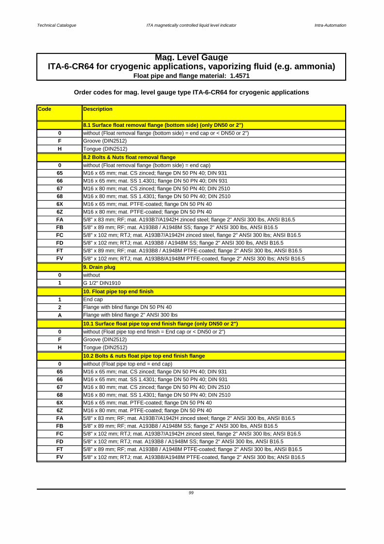
Technical Catalogue ITA magnetically controlled liquid level indicator Intra-Automation
Code Description
Mag. Level Gauge
F Groove (DIN2512)
8.2 Bolts & Nuts float removal flange0
M16 x 80 mm; mat. SS 1.4301; flange DN 50 PN 40; DIN 2510
6X
65 M16 x 65 mm; mat. CS zinced; flange DN 50 PN 40; DIN 931
66
10.1 Surface float pipe top end finish flange (only DN50 or 2")0F Groove (DIN2512)
H Tongue (DIN2512)
68
67 M16 x 80 mm; mat. CS zinced; flange DN 50 PN 40; DIN 2510
Flange with blind flange 2" ANSI 300 lbs
1
10.2 Bolts & nuts float pipe top end finish flange0 without (Float pipe top end = end cap)
End cap
2 Flange with blind flange DN 50 PN 40
without (Float removal flange (bottom side) = end cap)
H
65 M16 x 65 mm; mat. CS zinced; flange DN 50 PN 40; DIN 931
66 M16 x 65 mm; mat. SS 1.4301; flange DN 50 PN 40; DIN 931
ITA-6-CR64 for cryogenic applications, vaporizing fluid (e.g. ammonia)Float pipe and flange material: 1.4571
0 without (Float removal flange (bottom side) = end cap or < DN50 or 2")
Order codes for mag. level gauge type ITA-6-CR64 for cryogenic applications
Tongue (DIN2512)
8.1 Surface float removal flange (bottom side) (only DN50 or 2")
68 M16 x 80 mm; mat. SS 1.4301; flange DN 50 PN 40; DIN 2510
6X M16 x 65 mm; mat. PTFE-coated; flange DN 50 PN 40
FB 5/8" x 89 mm; RF; mat. A193B8 / A1948M SS; flange 2" ANSI 300 lbs, ANSI B16.5
FC 5/8" x 102 mm; RTJ; mat. A193B7/A1942H zinced steel, flange 2" ANSI 300 lbs; ANSI B16.5
6Z M16 x 80 mm; mat. PTFE-coated; flange DN 50 PN 40
FA 5/8" x 83 mm; RF; mat. A193B7/A1942H zinced steel; flange 2" ANSI 300 lbs, ANSI B16.5
G 1/2" DIN1910
10. Float pipe top end finish
A
FD 5/8" x 102 mm; RTJ; mat. A193B8 / A1948M SS; flange 2" ANSI 300 lbs, ANSI B16.5
FT 5/8" x 89 mm; RF; mat. A193B8 / A1948M PTFE-coated; flange 2" ANSI 300 lbs, ANSI B16.5
0 without
9. Drain plug
M16 x 65 mm; mat. PTFE-coated; flange DN 50 PN 40
6Z M16 x 80 mm; mat. PTFE-coated; flange DN 50 PN 40
FV 5/8" x 102 mm; RTJ; mat. A193B8/A1948M PTFE-coated, flange 2" ANSI 300 lbs; ANSI B16.5
M16 x 65 mm; mat. SS 1.4301; flange DN 50 PN 40; DIN 931
67 M16 x 80 mm; mat. CS zinced; flange DN 50 PN 40; DIN 2510
without (Float pipe top end finish = End cap or < DN50 or 2")
1
FC 5/8" x 102 mm; RTJ; mat. A193B7/A1942H zinced steel, flange 2" ANSI 300 lbs; ANSI B16.5
FD 5/8" x 102 mm; RTJ; mat. A193B8 / A1948M SS; flange 2" ANSI 300 lbs, ANSI B16.5
FA 5/8" x 83 mm; RF; mat. A193B7/A1942H zinced steel; flange 2" ANSI 300 lbs, ANSI B16.5
FB 5/8" x 89 mm; RF; mat. A193B8 / A1948M SS; flange 2" ANSI 300 lbs, ANSI B16.5
FT 5/8" x 89 mm; RF; mat. A193B8 / A1948M PTFE-coated; flange 2" ANSI 300 lbs, ANSI B16.5
FV 5/8" x 102 mm; RTJ; mat. A193B8/A1948M PTFE-coated, flange 2" ANSI 300 lbs; ANSI B16.5
99
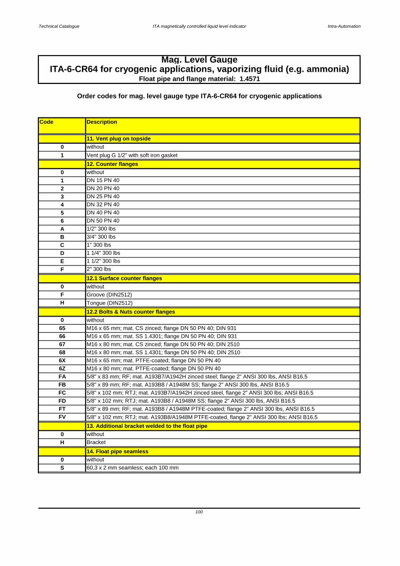
Technical Catalogue ITA magnetically controlled liquid level indicator Intra-Automation
Code Description
Float pipe and flange material: 1.4571ITA-6-CR64 for cryogenic applications, vaporizing fluid (e.g. ammonia)
Order codes for mag. level gauge type ITA-6-CR64 for cryogenic applications
A
DN 20 PN 40
4 DN 32 PN 40
DN 25 PN 40
1/2" 300 lbs
2
013. Additional bracket welded to the float pipe
F
1 1/2" 300 lbs
14. Float pipe seamless
without
S 60,3 x 2 mm seamless; each 100 mm
0 without
H Bracket
10
Groove (DIN2512)
D 1 1/4" 300 lbs
12.1 Surface counter flanges
E
1" 300 lbs
without0
F
B
5 DN 40 PN 40
12. Counter flanges1 Vent plug G 1/2" with soft iron gasket
Mag. Level Gauge
2" 300 lbs
C
without
3
3/4" 300 lbs
DN 15 PN 40
M16 x 65 mm; mat. CS zinced; flange DN 50 PN 40; DIN 931
66 M16 x 65 mm; mat. SS 1.4301; flange DN 50 PN 40; DIN 931
0 without
11. Vent plug on topside0 without
6 DN 50 PN 40
68 M16 x 80 mm; mat. SS 1.4301; flange DN 50 PN 40; DIN 2510
6X M16 x 65 mm; mat. PTFE-coated; flange DN 50 PN 40
H Tongue (DIN2512)
67 M16 x 80 mm; mat. CS zinced; flange DN 50 PN 40; DIN 2510
12.2 Bolts & Nuts counter flanges
65
FB 5/8" x 89 mm; RF; mat. A193B8 / A1948M SS; flange 2" ANSI 300 lbs, ANSI B16.5
FC 5/8" x 102 mm; RTJ; mat. A193B7/A1942H zinced steel, flange 2" ANSI 300 lbs; ANSI B16.5
6Z M16 x 80 mm; mat. PTFE-coated; flange DN 50 PN 40
FA 5/8" x 83 mm; RF; mat. A193B7/A1942H zinced steel; flange 2" ANSI 300 lbs, ANSI B16.5
100
FV 5/8" x 102 mm; RTJ; mat. A193B8/A1948M PTFE-coated, flange 2" ANSI 300 lbs; ANSI B16.5
FD 5/8" x 102 mm; RTJ; mat. A193B8 / A1948M SS; flange 2" ANSI 300 lbs, ANSI B16.5
FT 5/8" x 89 mm; RF; mat. A193B8 / A1948M PTFE-coated; flange 2" ANSI 300 lbs, ANSI B16.5
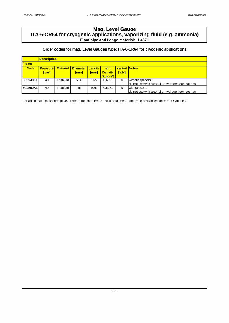
Technical Catalogue ITA magnetically controlled liquid level indicator Intra-Automation
Code Pressure[bar]
Material Diameter[mm]
Length[mm]
min. Density[kg/dm³]
vented[Y/N]
Notes
6C0240K1 40 Titanium 50,8 265 0,6391 N without spacers;do not use with alcohol or hydrogen compounds
6C0500K1 40 Titanium 45 525 0,5981 N with spacers;do not use with alcohol or hydrogen compounds
For additional accessories please refer to the chapters "Special equipment" and "Electrical accessories and Switches"
101
Mag. Level Gauge
Float pipe and flange material: 1.4571
Floats
Order codes for mag. Level Gauges type: ITA-6-CR64 for cryogenic applications
Description
ITA-6-CR64 for cryogenic applications, vaporizing fluid (e.g. ammonia)

Technical Catalogue ITA magnetically controlled liquid level indicator Intra-Automation
3.11.2 Order code scheme for ITA-3 Cryo
1. Type of level gauge ITA-3 Cryo2. C to C distance in mm [or inches]
3. Design4. Armaflex insulation
5. C to C distance > 5000 mm6. Process connection [side/side]
6.1 Surface side flanges 7. Side studs welded with T-pieces for 100 % X-ray-testing
8.2 Bolts & nuts float removal flange9. Drain plug
8. Float removal flangeSurface float removal flange8.1 Surface float removal flange
ITA-3-Cryo
12.1 Surface counter flanges12.2 Bolts & nuts counter flanges
12.1 Vent flange welded to end cap instead of vent plug12.2 Surface vent flange
10.Float pipe top end finish10.1 Surface top end finish flange
11. Vent plug at top end12. Counter flanges
102
13. Additional bracket welded to the float pipe14. Float pipe seamless
15. Float

Technical Catalogue ITA magnetically controlled liquid level indicator Intra-Automation
Key:1 Float pipe welded, dimensions 60,3 x 2 mm 9 Additional drain flange, open2 c to c distance 10 Float pipe top end finish3 Design (indication rail) 11 Vent plug5 Process connection side/side 12 Counter flanges6 Side studs welded with T pieces 13 Additional bracket
for 100 % X-ray testing 14 Float pipe seamless7 Float removal flange 15 Float8 Drain plug
3.12.1 ITA-7
Characteristics: PN64 / Float pipe and flange material: 1.4571
103
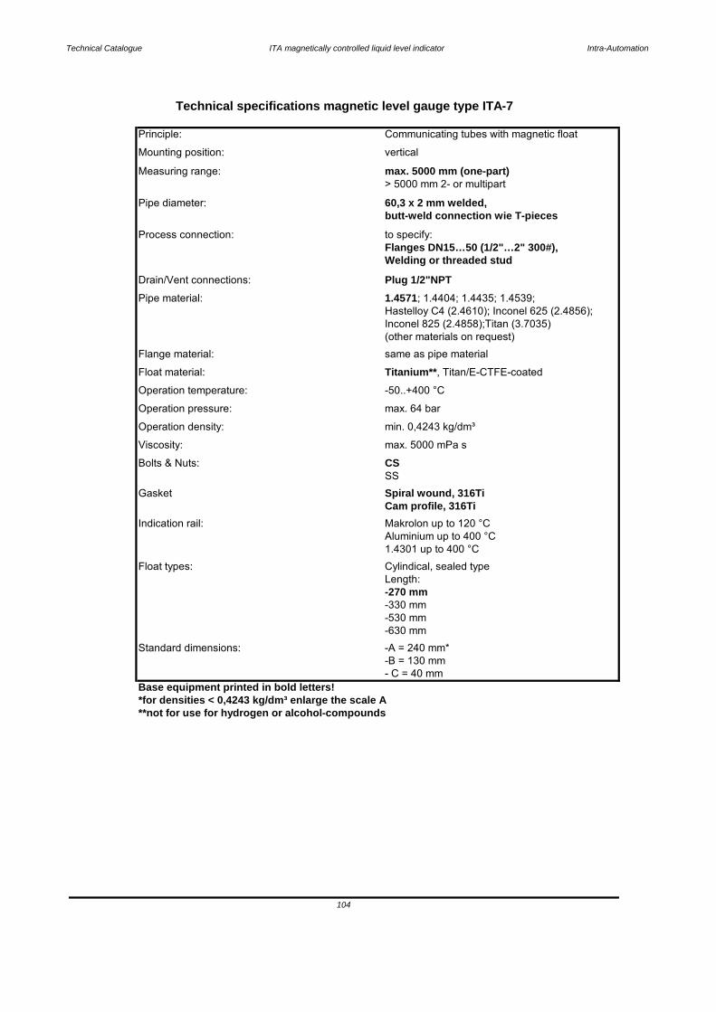
Technical Catalogue ITA magnetically controlled liquid level indicator Intra-Automation
Base equipment printed in bold letters!*for densities < 0,4243 kg/dm³ enlarge the scale A**not for use for hydrogen or alcohol-compounds
Principle: Communicating tubes with magnetic float
Technical specifications magnetic level gauge type ITA-7
Measuring range: max. 5000 mm (one-part)> 5000 mm 2- or multipart
Mounting position: vertical
butt-weld connection wie T-piecesPipe diameter: 60,3 x 2 mm welded,
Welding or threaded stud
Process connection: to specify:Flanges DN15…50 (1/2"…2" 300#),
Pipe material: 1.4571; 1.4404; 1.4435; 1.4539;Hastelloy C4 (2.4610); Inconel 625 (2.4856);
Drain/Vent connections: Plug 1/2"NPT
Flange material: same as pipe material
Inconel 825 (2.4858);Titan (3.7035)(other materials on request)
Operation temperature: -50..+400 °C
Float material: Titanium**, Titan/E-CTFE-coated
Operation density: min. 0,4243 kg/dm³
Operation pressure: max. 64 bar
Bolts & Nuts:
Viscosity: max. 5000 mPa s
Gasket Spiral wound, 316Ti
CSSS
Indication rail: Makrolon up to 120 °CCam profile, 316Ti
Float types: Cylindical, sealed type
Aluminium up to 400 °C1.4301 up to 400 °C
-530 mm-330 mm
Length: -270 mm
Standard dimensions: -A = 240 mm*-B = 130 mm
-630 mm
- C = 40 mm
104
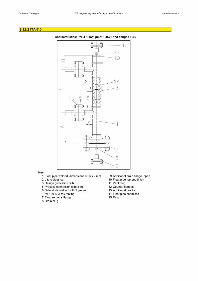
Technical Catalogue ITA magnetically controlled liquid level indicator Intra-Automation
Key:1 Float pipe welded, dimensions 60,3 x 2 mm 9 Additional drain flange, open2 c to c distance 10 Float pipe top end finish3 Design (indication rail) 11 Vent plug5 Process connection side/side 12 Counter flanges6 Side studs welded with T pieces 13 Additional bracket
for 100 % X-ray testing 14 Float pipe seamless7 Float removal flange 15 Float8 Drain plug
Characteristics: PN64 / Float pipe: 1.4571 and flanges : CS
3.12.2 ITA-7.0
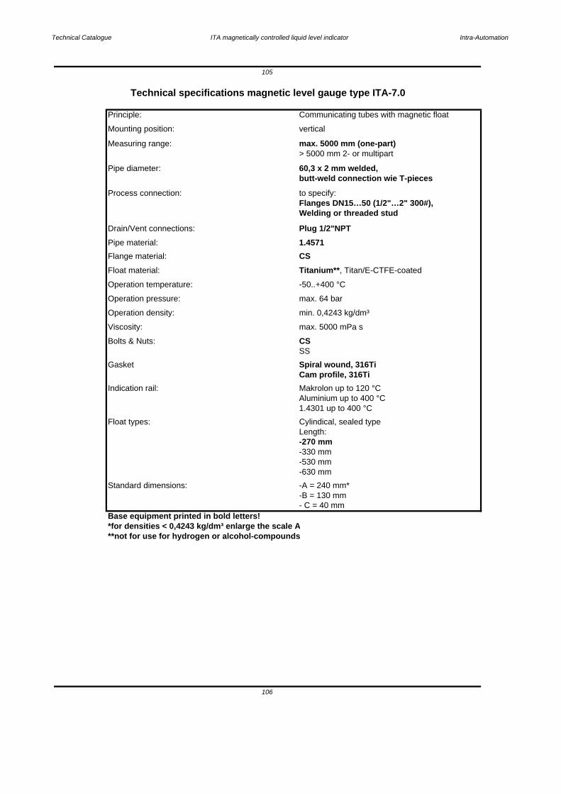
Technical Catalogue ITA magnetically controlled liquid level indicator Intra-Automation
Base equipment printed in bold letters!*for densities < 0,4243 kg/dm³ enlarge the scale A**not for use for hydrogen or alcohol-compounds
106
Indication rail:
- C = 40 mm
Standard dimensions: -A = 240 mm*-B = 130 mm
-630 mm
-330 mm-530 mm
Length: -270 mm
Float types: Cylindical, sealed type
Aluminium up to 400 °C1.4301 up to 400 °C
Cam profile, 316TiMakrolon up to 120 °C
SS
Gasket Spiral wound, 316Ti
Bolts & Nuts: CSViscosity: max. 5000 mPa s
Operation density: min. 0,4243 kg/dm³
Operation pressure: max. 64 bar
Operation temperature: -50..+400 °C
Float material: Titanium**, Titan/E-CTFE-coated
Flange material: CSPipe material: 1.4571Drain/Vent connections: Plug 1/2"NPT
Flanges DN15…50 (1/2"…2" 300#),Welding or threaded stud
Process connection: to specify:
Pipe diameter: 60,3 x 2 mm welded,butt-weld connection wie T-pieces
> 5000 mm 2- or multipartMeasuring range: max. 5000 mm (one-part)
Mounting position: vertical
105
Technical specifications magnetic level gauge type ITA-7.0
Principle: Communicating tubes with magnetic float
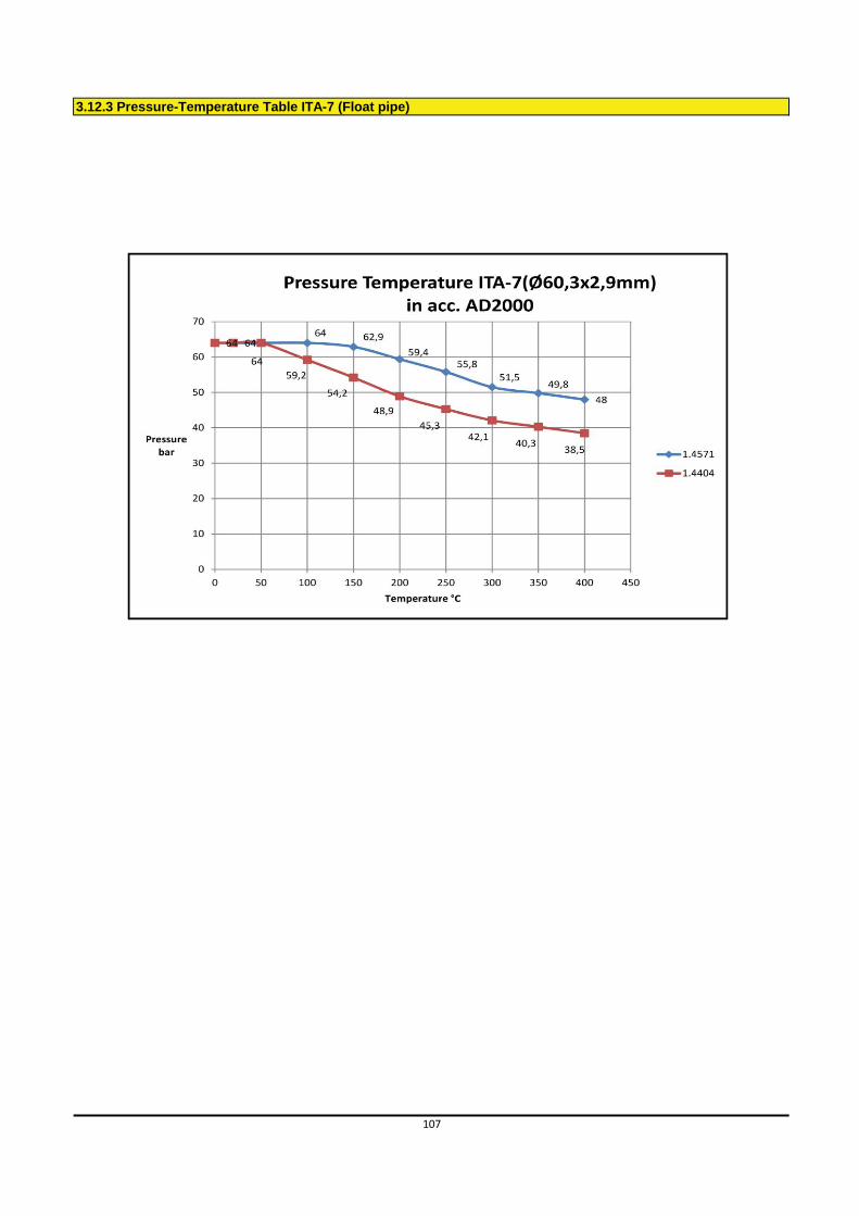
3.12.3 Pressure-Temperature Table ITA-7 (Float pipe)
107
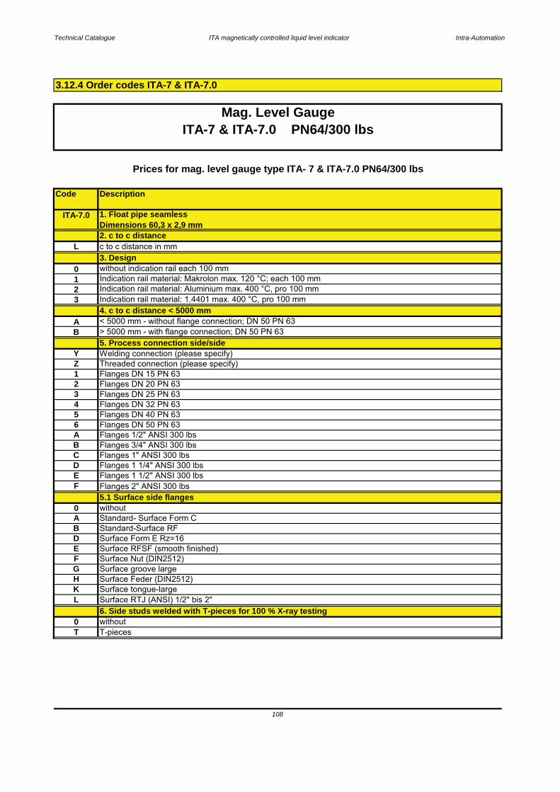
Technical Catalogue ITA magnetically controlled liquid level indicator Intra-Automation
Code Description
6. Side studs welded with T-pieces for 100 % X-ray testing0 without
L Surface RTJ (ANSI) 1/2" bis 2"
T T-pieces
F Surface Nut (DIN2512)G Surface groove largeH Surface Feder (DIN2512)K Surface tongue-large
D Surface Form E Rz=16E Surface RFSF (smooth finished)
A Standard- Surface Form CB Standard-Surface RF
5.1 Surface side flanges0 without
E Flanges 1 1/2" ANSI 300 lbsF Flanges 2" ANSI 300 lbs
C Flanges 1" ANSI 300 lbsD Flanges 1 1/4" ANSI 300 lbs
A Flanges 1/2" ANSI 300 lbs B Flanges 3/4" ANSI 300 lbs
5 Flanges DN 40 PN 636 Flanges DN 50 PN 63
3 Flanges DN 25 PN 634 Flanges DN 32 PN 63
1 Flanges DN 15 PN 632 Flanges DN 20 PN 63
Y Welding connection (please specify)Z Threaded connection (please specify)
Indication rail material: Makrolon max. 120 °C; each 100 mm
B > 5000 mm - with flange connection; DN 50 PN 635. Process connection side/side
4. c to c distance < 5000 mmA < 5000 mm - without flange connection; DN 50 PN 63
2. c to c distanceL c to c distance in mm
2 Indication rail material: Aluminium max. 400 °C, pro 100 mm3 Indication rail material: 1.4401 max. 400 °C, pro 100 mm
0 without indication rail each 100 mm1
Prices for mag. level gauge type ITA- 7 & ITA-7.0 PN64/300 lbs
Mag. Level GaugeITA-7 & ITA-7.0 PN64/300 lbs
3. Design
ITA-7.0 1. Float pipe seamlessDimensions 60,3 x 2,9 mm
3.12.4 Order codes ITA-7 & ITA-7.0
108
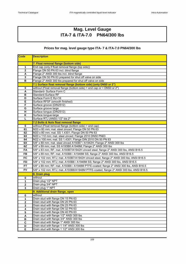
Technical Catalogue ITA magnetically controlled liquid level indicator Intra-Automation
Code Description
7.1 Surface float removal flange (bottom side) (only DN50 or 2")
Mag. Level GaugeITA-7 & ITA-7.0 PN64/300 lbs
3 Drain stud with flange DN 25 PN 634 Drain stud with flange DN 32 PN 63
E Drain stud with flange 1 1/2" ANSI 300 lbs
Drain stud with flange 3/4" ANSI 300 lbsC Drain stud with flange 1" ANSI 300 lbsB
1 Drain stud with flange DN 15 PN 632 Drain stud with flange DN 20 PN 63
5
Drain stud with flange 1 1/4" ANSI 300 lbs
Drain stud with flange DN 40 PN 63
D
A Drain stud with flange 1/2" ANSI 300 lbs
8. Drain plug
9. Additional drain flange, open
2 Drain plug 3/4" NPT3 Drain plug 1" NPT
6X 5/8" x 89 mm; mat. steel zinced A193B7 / A1942H; Flange 2" ANSI 300 lbs6Z 5/8" x 89 mm; mat. SS A193B8 A1948M; Flange 2" ANSI 300 lbs
63 M20 x 110 mm; mat. steel zinced; Flange 2510 DN50 PN6364 M22 x 100 mm; mat. SS 1.4301; Flange DIN 2510 DN 50 PN 63
61 M20 x 80 mm; mat. steel zinced; Flange DN 50 PN 6362 M20 x 80 mm; mat. SS 1.4301; Flange DN 50 PN 63
7.2 Bolts & Nuts float removal flange0 without (Float removal flange (bottom side) = end cap)
Prices for mag. level gauge type ITA- 7 & ITA-7.0 PN64/300 lbs
K Surface tongue-largeL Surface RTJ (ANSI) 1/2" bis 2"
G Surface groove largeH Surface tongue (DIN2512)
F Surface groove (DIN2512)
3 Flange DN 50 PN 63 prepared for shut off valve on sideB Flange 2" ANSI 300 lbs prepared for shut off valve on side
A Standard- Surface Form C0 without (Float removal flange (bottom side) = end cap or < DN50 or 2")
B Standard-Surface RF
E Surface RFSF (smooth finished)D Surface Form E Rz=16
2 Flange DN 50 PN 63 incl. blind flangeA Flange 2" ANSI 300 lbs incl. blind flange
7. Float removal flange (bottom side)1 End cap (only if float removal flange (top side))
FA 5/8" x 83 mm; RF; mat. A193B7/A1942H zinced steel; flange 2" ANSI 300 lbs, ANSI B16.5
FD 5/8" x 102 mm; RTJ; mat. A193B8 / A1948M SS; flange 2" ANSI 300 lbs, ANSI B16.5FT 5/8" x 89 mm; RF; mat. A193B8 / A1948M PTFE-coated; flange 2" ANSI 300 lbs, ANSI B16.5
FB 5/8" x 89 mm; RF; mat. A193B8 / A1948M SS; flange 2" ANSI 300 lbs, ANSI B16.5FC 5/8" x 102 mm; RTJ; mat. A193B7/A1942H zinced steel, flange 2" ANSI 300 lbs; ANSI B16.5
FV 5/8" x 102 mm; RTJ; mat. A193B8/A1948M PTFE-coated, flange 2" ANSI 300 lbs; ANSI B16.5
0 without
0 without1 Drain plug 1/2" NPT
109
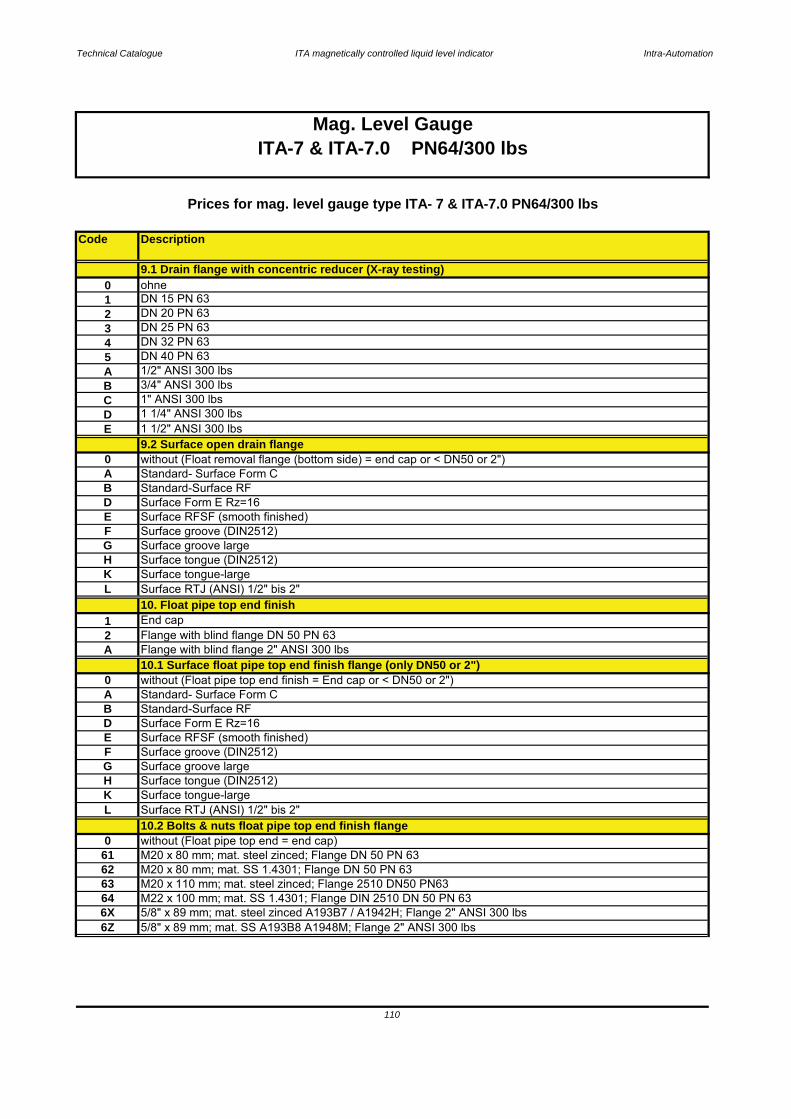
Technical Catalogue ITA magnetically controlled liquid level indicator Intra-Automation
Code Description
Mag. Level GaugeITA-7 & ITA-7.0 PN64/300 lbs
61 M20 x 80 mm; mat. steel zinced; Flange DN 50 PN 6362 M20 x 80 mm; mat. SS 1.4301; Flange DN 50 PN 63
64 M22 x 100 mm; mat. SS 1.4301; Flange DIN 2510 DN 50 PN 636X 5/8" x 89 mm; mat. steel zinced A193B7 / A1942H; Flange 2" ANSI 300 lbs6Z
0 without (Float pipe top end = end cap)
H Surface tongue (DIN2512)K Surface tongue-largeL Surface RTJ (ANSI) 1/2" bis 2"
10.2 Bolts & nuts float pipe top end finish flange
F Surface groove (DIN2512)G Surface groove large
D Surface Form E Rz=16E Surface RFSF (smooth finished)
A Standard- Surface Form CB Standard-Surface RF
10.1 Surface float pipe top end finish flange (only DN50 or 2")0 without (Float pipe top end finish = End cap or < DN50 or 2")
2 Flange with blind flange DN 50 PN 63A Flange with blind flange 2" ANSI 300 lbs
10. Float pipe top end finish1 End cap
L Surface RTJ (ANSI) 1/2" bis 2"
G Surface groove largeH Surface tongue (DIN2512)
E Surface RFSF (smooth finished)
K Surface tongue-large
F Surface groove (DIN2512)
D Surface Form E Rz=16
0 without (Float removal flange (bottom side) = end cap or < DN50 or 2")
E 1 1/2" ANSI 300 lbs
B Standard-Surface RF
Prices for mag. level gauge type ITA- 7 & ITA-7.0 PN64/300 lbs
A Standard- Surface Form C
C 1" ANSI 300 lbsD 1 1/4" ANSI 300 lbs
9.2 Surface open drain flange
2 DN 20 PN 63
4 DN 32 PN 63
9.1 Drain flange with concentric reducer (X-ray testing)0 ohne1 DN 15 PN 63
B 3/4" ANSI 300 lbs
3 DN 25 PN 63
A 1/2" ANSI 300 lbs 5 DN 40 PN 63
63 M20 x 110 mm; mat. steel zinced; Flange 2510 DN50 PN63
5/8" x 89 mm; mat. SS A193B8 A1948M; Flange 2" ANSI 300 lbs
110

Technical Catalogue ITA magnetically controlled liquid level indicator Intra-Automation
Code Description
1 1/2" ANSI 300 lbs
A 1/2" ANSI 300 lbs B 3/4" ANSI 300 lbs
Surface groove large
Surface Form E Rz=16E Surface RFSF (smooth finished)F
E
Surface tongue-largeL Surface RTJ (ANSI) 1/2" bis 2"K
11.3 Surface vent flange welded to end cap (only DN50 or 2")0 without (Vent flange welded to end cap = without)A Standard- Surface Form C
H Surface tongue (DIN2512)
B Standard-Surface RFD
C 1" ANSI 300 lbsD 1 1/4" ANSI 300 lbs
Surface groove (DIN2512)G
4 DN 32 PN 635 DN 40 PN 63
2 DN 20 PN 633 DN 25 PN 63
1 DN 15 PN 63
E Flange 1 1/2" ANSI 300 lbs (socket weld construction to end cap)11.2 Vent flange with concentric reducer (X-ray testing)
0 without
C Flange 1" ANSI 300 lbs (socket weld construction to end cap)D Flange 1 1/4" ANSI 300 lbs (socket weld construction to end cap)
A Flange 1/2" ANSI 300 lbs (socket weld construction to end cap)B Flange 3/4" ANSI 300 lbs (socket weld construction to end cap)
11.1 Vent flange welded to end cap instead of vent plug
5 Flange DN 40 PN 63 (socket weld construction to end cap)
1 Flange DN 15 PN 63 (socket weld construction to endcap)0 without
Flange DN 20 PN 63 (socket weld construction to end cap)
4Flange DN 25 PN 63 (socket weld construction to end cap)
3 Vent plug 3/4" NPT4 Vent plug 1" NPT
11. Vent plug at top end0 without
FA 5/8" x 83 mm; RF; mat. A193B7/A1942H zinced steel; flange 2" ANSI 300 lbs, ANSI B16.5FB 5/8" x 89 mm; RF; mat. A193B8 / A1948M SS; flange 2" ANSI 300 lbs, ANSI B16.5
ITA-7 & ITA-7.0 PN64/300 lbsMag. Level Gauge
Prices for mag. level gauge type ITA- 7 & ITA-7.0 PN64/300 lbs
FT 5/8" x 89 mm; RF; mat. A193B8 / A1948M PTFE-coated; flange 2" ANSI 300 lbs, ANSI B16.5FV 5/8" x 102 mm; RTJ; mat. A193B8/A1948M PTFE-coated, flange 2" ANSI 300 lbs; ANSI B16.5
FC 5/8" x 102 mm; RTJ; mat. A193B7/A1942H zinced steel, flange 2" ANSI 300 lbs; ANSI B16.5FD 5/8" x 102 mm; RTJ; mat. A193B8 / A1948M SS; flange 2" ANSI 300 lbs, ANSI B16.5
1 Vent plug G 1/2" DIN9102 Vent plug 1/2" NPT
2
Flange DN 32 PN 63 (socket weld construction to end cap)3
111
10.2 Bolts & nuts float pipe top end finish flange (Continuation)
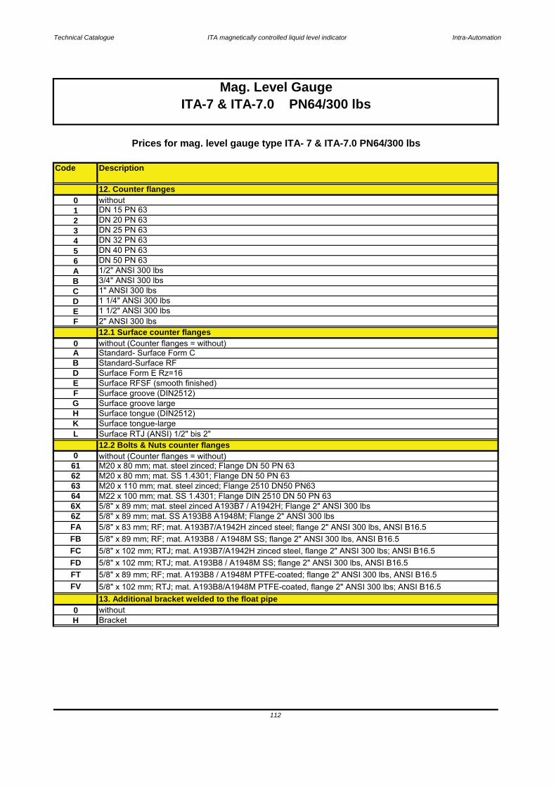
Technical Catalogue ITA magnetically controlled liquid level indicator Intra-Automation
Code Description
13. Additional bracket welded to the float pipe0 withoutH Bracket
12.2 Bolts & Nuts counter flanges0 without (Counter flanges = without)
6162 M20 x 80 mm; mat. SS 1.4301; Flange DN 50 PN 6363
K Surface tongue-largeL Surface RTJ (ANSI) 1/2" bis 2"
G Surface groove largeH Surface tongue (DIN2512)
E Surface RFSF (smooth finished)F Surface groove (DIN2512)
B Standard-Surface RFD Surface Form E Rz=16
F 2" ANSI 300 lbsE 1 1/2" ANSI 300 lbs
A Standard- Surface Form C
12.1 Surface counter flanges0 without (Counter flanges = without)
D 1 1/4" ANSI 300 lbs
6 DN 50 PN 63A 1/2" ANSI 300 lbs
C 1" ANSI 300 lbsB 3/4" ANSI 300 lbs
5 DN 40 PN 634 DN 32 PN 63
12. Counter flanges
Prices for mag. level gauge type ITA- 7 & ITA-7.0 PN64/300 lbs
3 DN 25 PN 63
1 DN 15 PN 632 DN 20 PN 63
0 without
M20 x 80 mm; mat. steel zinced; Flange DN 50 PN 63
Mag. Level GaugeITA-7 & ITA-7.0 PN64/300 lbs
6Z 5/8" x 89 mm; mat. SS A193B8 A1948M; Flange 2" ANSI 300 lbsFA 5/8" x 83 mm; RF; mat. A193B7/A1942H zinced steel; flange 2" ANSI 300 lbs, ANSI B16.5
M20 x 110 mm; mat. steel zinced; Flange 2510 DN50 PN6364 M22 x 100 mm; mat. SS 1.4301; Flange DIN 2510 DN 50 PN 636X 5/8" x 89 mm; mat. steel zinced A193B7 / A1942H; Flange 2" ANSI 300 lbs
FD 5/8" x 102 mm; RTJ; mat. A193B8 / A1948M SS; flange 2" ANSI 300 lbs, ANSI B16.5FT 5/8" x 89 mm; RF; mat. A193B8 / A1948M PTFE-coated; flange 2" ANSI 300 lbs, ANSI B16.5
FB 5/8" x 89 mm; RF; mat. A193B8 / A1948M SS; flange 2" ANSI 300 lbs, ANSI B16.5FC 5/8" x 102 mm; RTJ; mat. A193B7/A1942H zinced steel, flange 2" ANSI 300 lbs; ANSI B16.5
112
FV 5/8" x 102 mm; RTJ; mat. A193B8/A1948M PTFE-coated, flange 2" ANSI 300 lbs; ANSI B16.5
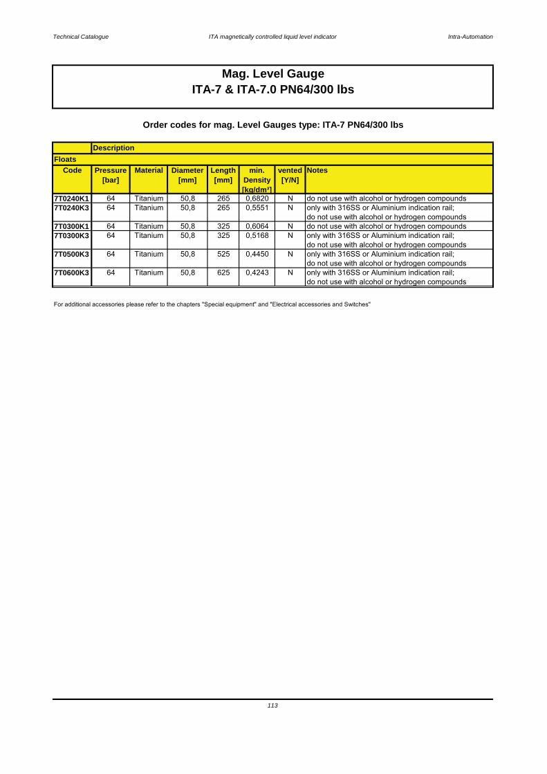
Technical Catalogue ITA magnetically controlled liquid level indicator Intra-Automation
Code Pressure[bar]
Material Diameter[mm]
Length[mm]
min. Density[kg/dm³]
vented[Y/N]
Notes
7T0240K1 64 Titanium 50,8 265 0,6820 N do not use with alcohol or hydrogen compounds7T0240K3 64 Titanium 50,8 265 0,5551 N only with 316SS or Aluminium indication rail;
do not use with alcohol or hydrogen compounds7T0300K1 64 Titanium 50,8 325 0,6064 N do not use with alcohol or hydrogen compounds7T0300K3 64 Titanium 50,8 325 0,5168 N only with 316SS or Aluminium indication rail;
do not use with alcohol or hydrogen compounds7T0500K3 64 Titanium 50,8 525 0,4450 N only with 316SS or Aluminium indication rail;
do not use with alcohol or hydrogen compounds7T0600K3 64 Titanium 50,8 625 0,4243 N only with 316SS or Aluminium indication rail;
do not use with alcohol or hydrogen compounds
113
Mag. Level GaugeITA-7 & ITA-7.0 PN64/300 lbs
For additional accessories please refer to the chapters "Special equipment" and "Electrical accessories and Switches"
Order codes for mag. Level Gauges type: ITA-7 PN64/300 lbs
DescriptionFloats

Technical Catalogue ITA magnetically controlled liquid level indicator Intra-Automation
3.12.4 Order code scheme for ITA-7 & ITA-7.0
1. Type of level gauge ITA-7 or ITA-7.02. C to C distance in mm [or inches]
3. Design4. C to C distance > 5000 mm
5. Process connection [side/side]5.1 Surface side flanges
6. Side studs welded with T-pieces for 100 % X-ray-testing7. Float removal flange
7.1 Surface float removal flange7.2 Bolts & nuts float removal flange
8. Drain plug9. Additional drain flange, open
ITA-7.0
9.1 Drain flange with concentric reducer (X-ray testing)9.2 Surface open drain flange
ITA-7
11.1 Vent flange welded to end cap instead of vent plug11.2 Vent flange with concentric reducer (X-ray testing)
11.3 Surface vent flange welded to end cap 12. Counter flanges
10. Float pipe top end finish10.1 Surface top end finish flange
10.2 Bolts and nuts rop end finish flange11. Vent plug at top end
114
12.1 Surface counter flanges12.2 Bolts & nuts counter flanges
13. Additional bracket welded to the float pipe14. Float

Technical Catalogue ITA magnetically controlled liquid level indicator Intra-Automation
Key:1 Float pipe PVC, dimensions 63 x 47 mm2 c to c distance3 Design (indication rail)6 Process connection side/side7 Drain plug8 Float pipe top end finish9 Mounting link
10 Float
3.13.1 ITA-8.1 [PVC]
Characteristics: PN6 / Material: PVC
115

Technical Catalogue ITA magnetically controlled liquid level indicator Intra-Automation
Base equipment printed in bold letters!*for densities < 0,75 kg/dm³ enlarge scale A
Principle: Communicating tubes with magnetic float
Technical specifications magnetic level gauge type ITA-8.1
Measuring range: max. 5000 mm (one-part)> 5000 mm 2- or multipart
Mounting position: vertical
Process connection: to specify:
Pipe diameter: 63 x 4,7 mm
Drain/Vent connections: Plug R1/2" (for more please see order codes)
Flanges DN15…50 (1/2"…2")
Flange material: same as pipe materialPipe material: PVC
Float material: PVC
Operation pressure: max. 6 bar
Operation temperature: -30..+60 °C
Bolts & Nuts: SS
Operation density: min. 0,75 kg/dm³
Viscosity: max. 5000 mPa s
Gasket Viton
Float types: Cylindical, sealed type
Indication rail: Aluminium1.4301
- 135 mm
Standard dimensions: A = 240 mm*
Length: - 255 mm
116
B = 130 mmC = 110 mm
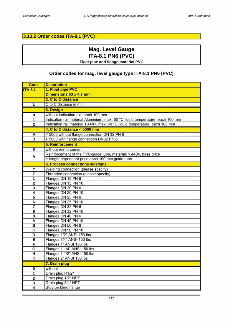
Technical Catalogue ITA magnetically controlled liquid level indicator Intra-Automation
CodeITA-8.1
L
012
AB
0
YZ123456789ABCDEFGHK
01234
117
Stud on blind flange
Drain plug 1/2" NPT
Threaded connection (please specify)
Flanges DN 50 PN 6
Drain plug R1/2"
Flanges DN 50 PN 10Flanges 1/2" ANSI 150 lbsFlanges 3/4" ANSI 150 lbs
Flanges DN 20 PN 10
Drain plug 3/4" NPT
Flanges 1" ANSI 150 lbsFlanges 1 1/4" ANSI 150 lbs
Flanges DN 40 PN 10
Flanges 1 1/2" ANSI 150 lbsFlanges 2" ANSI 150 lbs7. Drain plugwithout
Flanges DN 32 PN 10Flanges DN 40 PN 6
Flanges DN 20 PN 6
Flanges DN 25 PN 6Flanges DN 25 PN 10Flanges DN 32 PN 6
Flanges DN 15 PN 10
Reinforcement of the PVC-guide tube, material: 1.4404, base price+ length dependent price each 100 mm guide tube6. Process connections side/sideWelding connection (please specify)
> 5000 with flange connection DN32 PN 6
Flanges DN 15 PN 6
5. Reinforcementwithout reinforcement
4. C to C distance < 5000 mm< 5000 without flange connection DN 32 PN 6
Order codes for mag. level gauge type ITA-8.1 PN6 (PVC)
Description1. Float pipe PVCDimensions 63 x 4,7 mm2. C to C distance
3.13.2 Order codes ITA-8.1 (PVC)
Indication rail material 1.4401, max. 60 °C liquid temperature, each 100 mm
Float pipe and flange material PVC
A
C to C distance in mm
without indication rail, each 100 mm3. Design
Indication rail material Aluminium, max. 60 °C liquid temperature, each 100 mm
Mag. Level GaugeITA-8.1 PN6 (PVC)
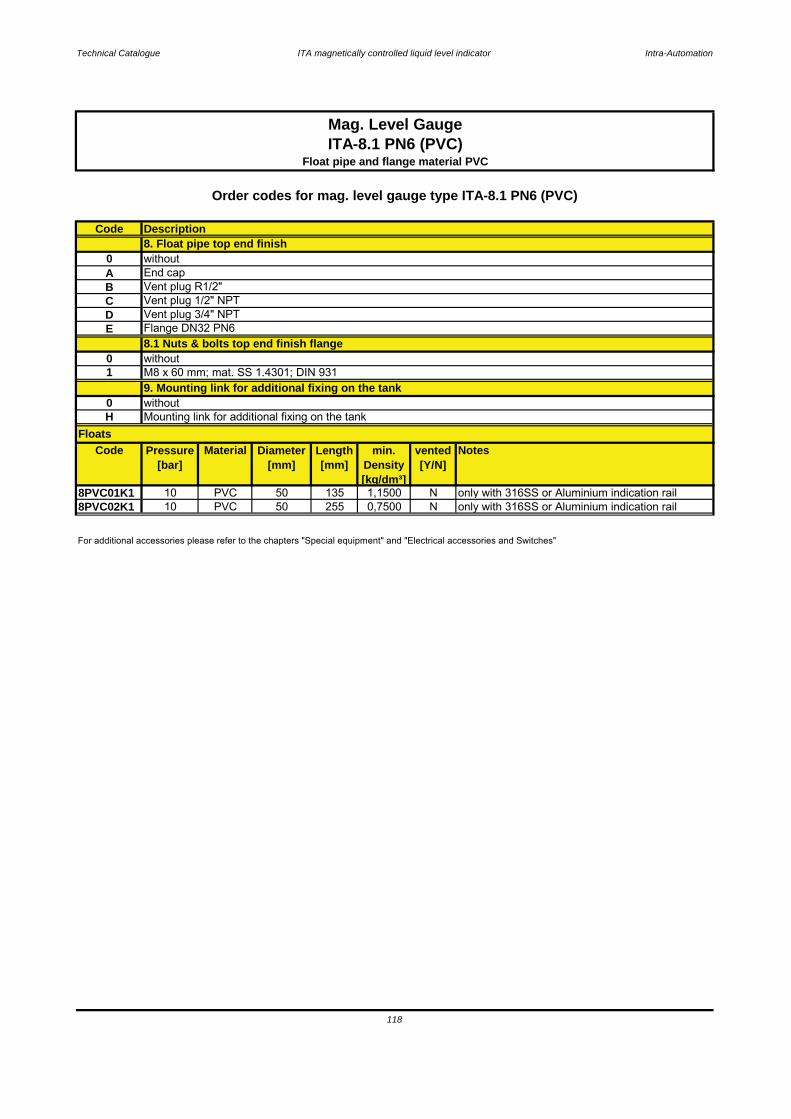
Technical Catalogue ITA magnetically controlled liquid level indicator Intra-Automation
Code
0ABCDE
01
0H
Code Pressure[bar]
Material Diameter[mm]
Length[mm]
min. Density[kg/dm³]
vented[Y/N]
Notes
8PVC01K1 10 PVC 50 135 1,1500 N only with 316SS or Aluminium indication rail8PVC02K1 10 PVC 50 255 0,7500 N only with 316SS or Aluminium indication rail
8. Float pipe top end finishwithoutEnd cap
M8 x 60 mm; mat. SS 1.4301; DIN 931without
Vent plug 1/2" NPT
Mag. Level GaugeITA-8.1 PN6 (PVC)
Float pipe and flange material PVC
Order codes for mag. level gauge type ITA-8.1 PN6 (PVC)
Description
For additional accessories please refer to the chapters "Special equipment" and "Electrical accessories and Switches"
Vent plug 3/4" NPT
118
Vent plug R1/2"
Mounting link for additional fixing on the tankFloats
9. Mounting link for additional fixing on the tankwithout
8.1 Nuts & bolts top end finish flange Flange DN32 PN6
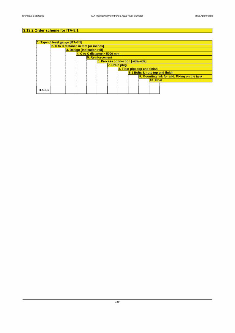
Technical Catalogue ITA magnetically controlled liquid level indicator Intra-Automation
ITA-8.1
10. Float
5. Reinforcement6. Process connection [side/side]
7. Drain plug8. Float pipe top end finish
3.13.2 Order scheme for ITA-8.1
119
1. Type of level gauge [ITA-8.1]2. C to C distance in mm [or inches]
3. Design [Indication rail]4. C to C distance > 5000 mm
8.1 Bolts & nuts top end finish9. Mounting link for add. Fixing on the tank
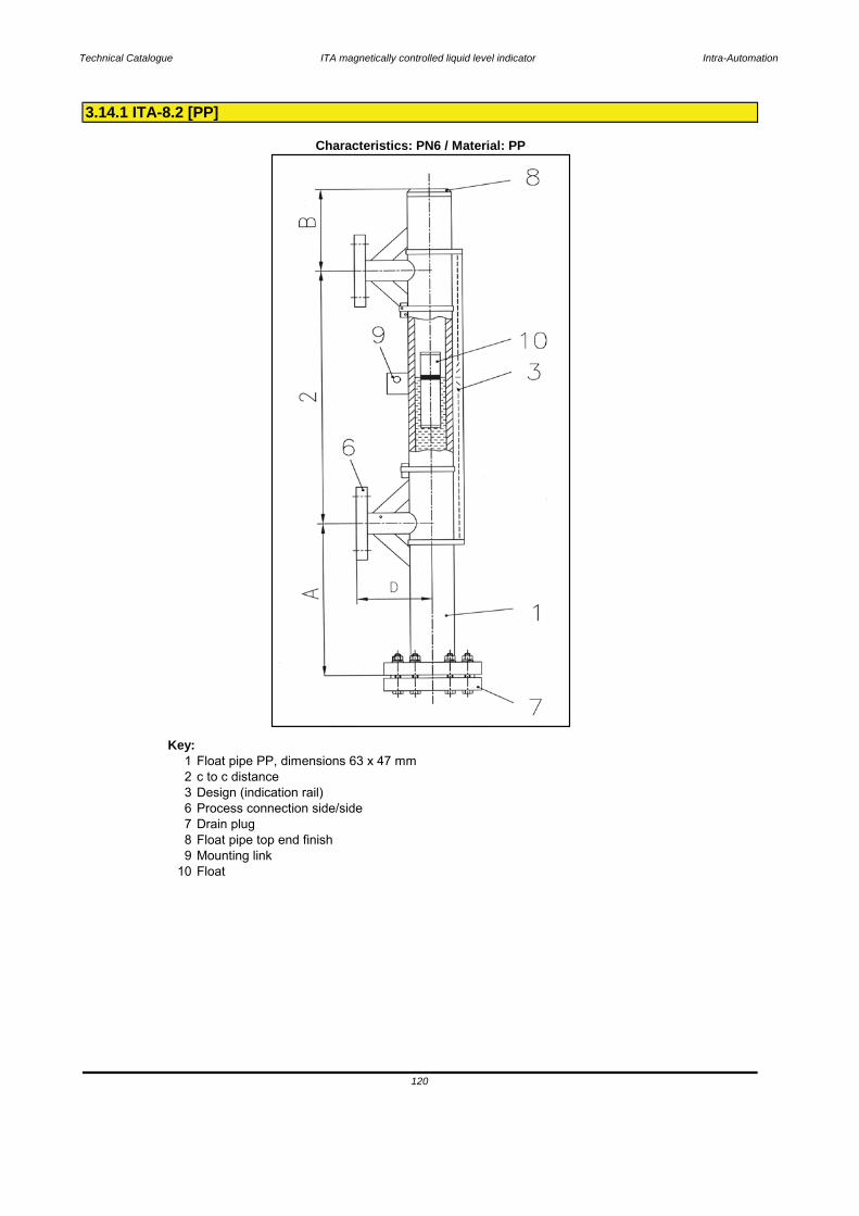
Technical Catalogue ITA magnetically controlled liquid level indicator Intra-Automation
Key:1 Float pipe PP, dimensions 63 x 47 mm2 c to c distance3 Design (indication rail)6 Process connection side/side7 Drain plug8 Float pipe top end finish9 Mounting link
10 Float
3.14.1 ITA-8.2 [PP]
Characteristics: PN6 / Material: PP
120
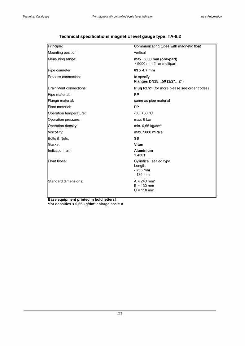
Technical Catalogue ITA magnetically controlled liquid level indicator Intra-Automation
Base equipment printed in bold letters!*for densities < 0,65 kg/dm³ enlarge scale A
Standard dimensions: A = 240 mm*
121
B = 130 mmC = 110 mm
Length: - 255 mm- 135 mm
1.4301Float types: Cylindical, sealed type
Gasket VitonIndication rail: Aluminium
Bolts & Nuts: SSViscosity: max. 5000 mPa s
Operation pressure: max. 6 bar
Operation density: min. 0,65 kg/dm³
Operation temperature: -30..+80 °C
Flange material: same as pipe material
Float material: PP
Pipe material: PP
Flanges DN15…50 (1/2"…2")
Drain/Vent connections: Plug R1/2" (for more please see order codes)
Pipe diameter: 63 x 4,7 mm
Process connection: to specify:
Measuring range: max. 5000 mm (one-part)> 5000 mm 2- or multipart
Mounting position: vertical
Technical specifications magnetic level gauge type ITA-8.2
Principle: Communicating tubes with magnetic float
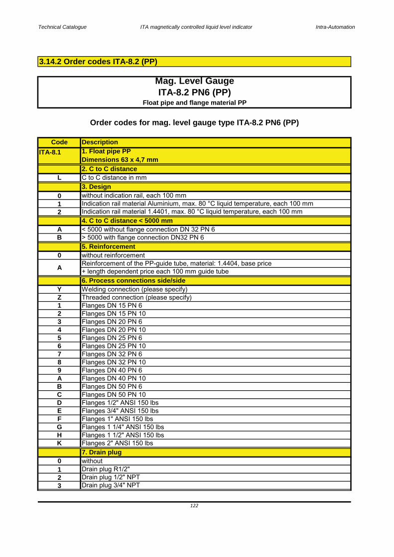
Technical Catalogue ITA magnetically controlled liquid level indicator Intra-Automation
CodeITA-8.1
L
012
AB
0
YZ123456789ABCDEFGHK
0123
3.14.2 Order codes ITA-8.2 (PP)
122
Flanges 1 1/2" ANSI 150 lbsFlanges 2" ANSI 150 lbs7. Drain plugwithout
Drain plug 1/2" NPT
Flanges DN 32 PN 10Flanges DN 40 PN 6
Flanges 1" ANSI 150 lbs
Drain plug 3/4" NPT
Flanges DN 40 PN 10Flanges DN 50 PN 6Flanges DN 50 PN 10Flanges 1/2" ANSI 150 lbsFlanges 3/4" ANSI 150 lbs
Drain plug R1/2"
Flanges DN 25 PN 6Flanges DN 25 PN 10Flanges DN 32 PN 6
Flanges 1 1/4" ANSI 150 lbs
Description1. Float pipe PPDimensions 63 x 4,7 mm2. C to C distance
Indication rail material 1.4401, max. 80 °C liquid temperature, each 100 mmIndication rail material Aluminium, max. 80 °C liquid temperature, each 100 mm
Flanges DN 20 PN 6Flanges DN 20 PN 10
Mag. Level GaugeITA-8.2 PN6 (PP)
4. C to C distance < 5000 mm< 5000 without flange connection DN 32 PN 6
Order codes for mag. level gauge type ITA-8.2 PN6 (PP)
Flanges DN 15 PN 10
A Reinforcement of the PP-guide tube, material: 1.4404, base price+ length dependent price each 100 mm guide tube6. Process connections side/side
> 5000 with flange connection DN32 PN 6
Flanges DN 15 PN 6
5. Reinforcementwithout reinforcement
Threaded connection (please specify)Welding connection (please specify)
C to C distance in mm
without indication rail, each 100 mm3. Design
Float pipe and flange material PP

Technical Catalogue ITA magnetically controlled liquid level indicator Intra-Automation
ABCDE
01
01
Code Pressure[bar]
Material Diameter[mm]
Length[mm]
min. Density[kg/dm³]
vented[Y/N]
Notes
8PP001K1 10 PP 50 135 0,9500 N only with 316SS or Aluminium indication rail8PP002K1 10 PP 50 255 0,6500 N only with 316SS or Aluminium indication rail
8. Float pipe top end finish
123
without
Vent plug R1/2"Vent plug 1/2" NPT
End cap
8.1 Nuts & bolts top end finish flange withoutM8 x 60 mm; mat. SS 1.4301; DIN 9319. Mounting link for additional fixing on the tank
Mag. Level GaugeITA-8.2 PN6 (PP)
Float pipe and flanges material: PP
For additional accessories please refer to the chapters "Special equipment" and "Electrical accessories and Switches"
Order codes for mag. Level Gauges type: ITA-8.2 PN6 (PP)
Description
9. Floats
Vent plug 3/4" NPT
Mounting link for additional fixing on the tank
Flange DN32 PN6

Technical Catalogue ITA magnetically controlled liquid level indicator Intra-Automation
ITA-8.2
6. Process connection [side/side]7. Drain plug
124
8. Float pipe top end finish8.1 Bolts & nuts top end finish
9. Mounting link for add. Fixing on the tank10. Float
3.14.2 Order scheme for ITA-8.2
1. Type of level gauge [ITA-8.2]2. C to C distance in mm [or inches]
3. Design [Indication rail]4. C to C distance > 5000 mm
5. Reinforcement
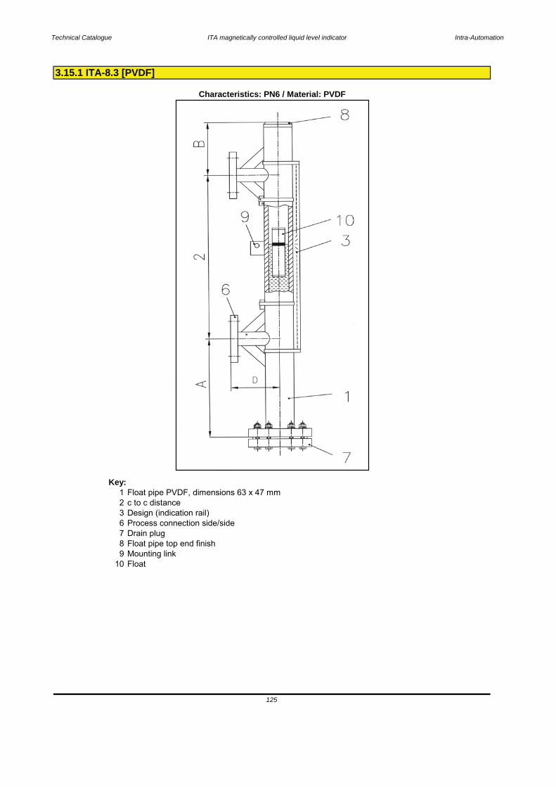
Technical Catalogue ITA magnetically controlled liquid level indicator Intra-Automation
Key:1 Float pipe PVDF, dimensions 63 x 47 mm2 c to c distance3 Design (indication rail)6 Process connection side/side7 Drain plug8 Float pipe top end finish9 Mounting link
10 Float
3.15.1 ITA-8.3 [PVDF]
Characteristics: PN6 / Material: PVDF
125

Technical Catalogue ITA magnetically controlled liquid level indicator Intra-Automation
Base equipment printed in bold letters!*for densities < 0,85 kg/dm³ enlarge scale A
Standard dimensions: A = 240 mm*
126
B = 130 mmC = 110 mm
Length: - 255 mm- 135 mm
1.4301Float types: Cylindical, sealed type
Gasket VitonIndication rail: Aluminium
Bolts & Nuts: SSViscosity: max. 5000 mPa s
Operation pressure: max. 6 bar
Operation density: min. 0,85 kg/dm³
Operation temperature: -40..+120 °C
Flange material: same as pipe material
Float material: PVDF
Pipe material: PVDF
Flanges DN15…50 (1/2"…2")
Drain/Vent connections: Plug R1/2" (for more please see order codes)
Pipe diameter: 63 x 4,7 mm
Process connection: to specify:
Measuring range: max. 5000 mm (one-part)> 5000 mm 2- or multipart
Mounting position: vertical
Technical specifications magnetic level gauge type ITA-8.3
Principle: Communicating tubes with magnetic float

Technical Catalogue ITA magnetically controlled liquid level indicator Intra-Automation
CodeITA-8.3
L
012
AB
0
YZ123456789ABCDEFGHK
0123
3.15.2 Order codes ITA-8.3 (PVDF)
127
Flanges 1 1/2" ANSI 150 lbsFlanges 2" ANSI 150 lbs7. Drain plugwithout
Drain plug 1/2" NPT
Flanges DN 32 PN 10Flanges DN 40 PN 6
Flanges 1" ANSI 150 lbs
Drain plug 3/4" NPT
Flanges DN 40 PN 10Flanges DN 50 PN 6Flanges DN 50 PN 10Flanges 1/2" ANSI 150 lbsFlanges 3/4" ANSI 150 lbs
Drain plug R1/2"
Flanges DN 25 PN 6Flanges DN 25 PN 10Flanges DN 32 PN 6
Flanges 1 1/4" ANSI 150 lbs
Description1. Float pipe PVDFDimensions 63 x 2 mm2. C to C distance
Indication rail material 1.4401, max. 120 °C liquid temperature, each 100 mmIndication rail material Aluminium, max. 120 °C liquid temperature, each 100 mm
Flanges DN 20 PN 6Flanges DN 20 PN 10
Mag. Level GaugeITA-8.3 PN6 (PVDF)
4. C to C distance < 5000 mm< 5000 without flange connection DN 32 PN 6
Order codes for mag. level gauge type ITA-8.3 PN6 (PVDF)
Flanges DN 15 PN 10
A Reinforcement of the PVDF-guide tube, material: 1.4404, base price+ length dependent price each 100 mm guide tube6. Process connections side/side
> 5000 with flange connection DN32 PN 6
Flanges DN 15 PN 6
5. Reinforcementwithout reinforcement
Threaded connection (please specify)Welding connection (please specify)
C to C distance in mm
without indication rail, each 100 mm3. Design
Float pipe and flange material PVDF

Technical Catalogue ITA magnetically controlled liquid level indicator Intra-Automation
ABCDE
01
01
Code Pressure[bar]
Material Diameter[mm]
Length[mm]
min. Density[kg/dm³]
vented[Y/N]
Notes
8PVDF1K1 10 PVDF 50 135 1,3000 N only with 316SS or Aluminium indication rail8PVDF2K1 10 PVDF 50 255 0,8500 N only with 316SS or Aluminium indication rail
8. Float pipe top end finish
128
without
Vent plug R1/2"Vent plug 1/2" NPT
End cap
8.1 Nuts & bolts top end finish flange withoutM8 x 60 mm; mat. SS 1.4301; DIN 9319. Mounting link for additional fixing on the tank
Mag. Level GaugeITA-8.3 PN6 (PVDF)
Float pipe and flanges material: PVDF
For additional accessories please refer to the chapters "Special equipment" and "Electrical accessories and Switches"
Order codes for mag. Level Gauges type: ITA-8.3 PN6 (PVDF)
Description
Floats
Vent plug 3/4" NPT
Mounting link for additional fixing on the tank
Flange DN32 PN6

Technical Catalogue ITA magnetically controlled liquid level indicator Intra-Automation
ITA-8.3
6. Process connection [side/side]7. Drain plug
129
8. Float pipe top end finish8.1 Bolts & nuts top end finish
9. Mounting link for add. Fixing on the tank10. Float
3.15.2 Order scheme for ITA-8.3
1. Type of level gauge [ITA-8.3]2. C to C distance in mm [or inches]
3. Design [Indication rail]4. C to C distance > 5000 mm
5. Reinforcement

Technical Catalogue ITA magnetically controlled liquid level indicator Intra-Automation
Key:1 Float pipe PVC, dimensions 63 x 4,7 mm2 Measuring length3 Design (indication rail)4 Process connection on tank5 Follower magnet guide tube topside finish
(mounted from top of tank)
3.16.1 ITA-9.1 [PVC]
Characteristics: PN6 / Material: PVC
130
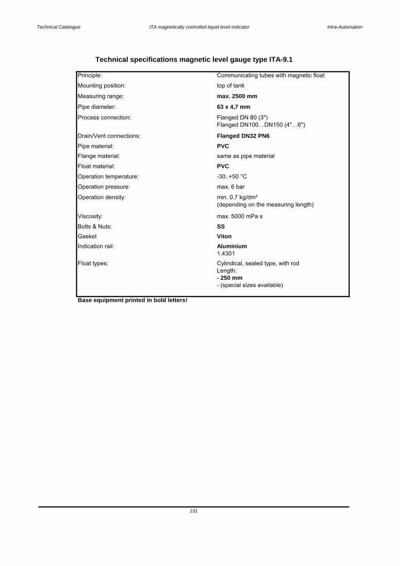
Technical Catalogue ITA magnetically controlled liquid level indicator Intra-Automation
Base equipment printed in bold letters!
- 250 mm
Viscosity: max. 5000 mPa s
Float types: Cylindical, sealed type, with rod
1.4301
131
- (special sizes available)
Length:
Indication rail: AluminiumGasket Viton
Operation density: min. 0,7 kg/dm³(depending on the measuring length)
Bolts & Nuts: SS
Operation pressure: max. 6 bar
Float material: PVCOperation temperature: -30..+50 °C
Flange material: same as pipe material
Drain/Vent connections: Flanged DN32 PN6Pipe material: PVC
Process connection: Flanged DN 80 (3")Flanged DN100…DN150 (4"…6")
Pipe diameter: 63 x 4,7 mm
Measuring range: max. 2500 mm
Mounting position: top of tank
Technical specifications magnetic level gauge type ITA-9.1
Principle: Communicating tubes with magnetic float
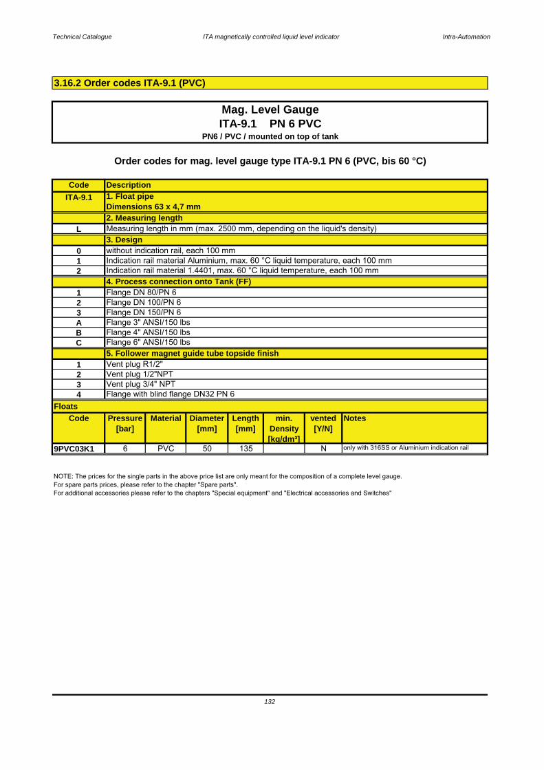
Technical Catalogue ITA magnetically controlled liquid level indicator Intra-Automation
CodeITA-9.1
L
012
123ABC
1234
Code Pressure[bar]
Material Diameter[mm]
Length[mm]
min. Density[kg/dm³]
vented[Y/N]
Notes
9PVC03K1 6 PVC 50 135 N only with 316SS or Aluminium indication rail
3.16.2 Order codes ITA-9.1 (PVC)
132
Floats
NOTE: The prices for the single parts in the above price list are only meant for the composition of a complete level gauge.For spare parts prices, please refer to the chapter "Spare parts".For additional accessories please refer to the chapters "Special equipment" and "Electrical accessories and Switches"
Vent plug 1/2"NPTVent plug 3/4" NPTFlange with blind flange DN32 PN 6
Flange DN 150/PN 6Flange 3" ANSI/150 lbsFlange 4" ANSI/150 lbs
Indication rail material 1.4401, max. 60 °C liquid temperature, each 100 mm
3. Designwithout indication rail, each 100 mmIndication rail material Aluminium, max. 60 °C liquid temperature, each 100 mm
Vent plug R1/2"
4. Process connection onto Tank (FF)Flange DN 80/PN 6Flange DN 100/PN 6
Flange 6" ANSI/150 lbs5. Follower magnet guide tube topside finish
Mag. Level GaugeITA-9.1 PN 6 PVC
PN6 / PVC / mounted on top of tank
Measuring length in mm (max. 2500 mm, depending on the liquid's density)
Order codes for mag. level gauge type ITA-9.1 PN 6 (PVC, bis 60 °C)
Description1. Float pipeDimensions 63 x 4,7 mm2. Measuring length

Technical Catalogue ITA magnetically controlled liquid level indicator Intra-Automation
ITA-9.1
5. Follower magnet guide tube topside finish6. Float
3.16.2 Order scheme for ITA-9.1
133
1. Type of level gauge [ITA-9.1]2. Measuring length in mm [or inches]
3. Design [Indication rail]4. Process connection on the tank [FF]
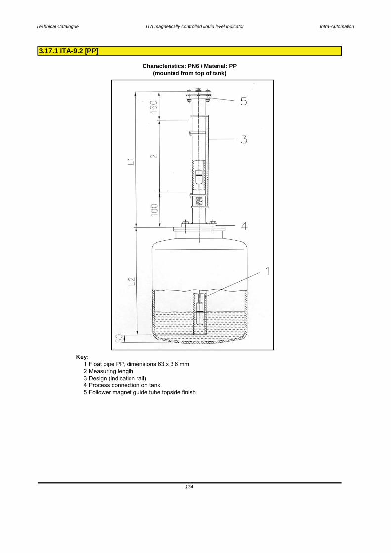
Technical Catalogue ITA magnetically controlled liquid level indicator Intra-Automation
Key:1 Float pipe PP, dimensions 63 x 3,6 mm2 Measuring length3 Design (indication rail)4 Process connection on tank5 Follower magnet guide tube topside finish
3.17.1 ITA-9.2 [PP]
Characteristics: PN6 / Material: PP(mounted from top of tank)
134

Technical Catalogue ITA magnetically controlled liquid level indicator Intra-Automation
Base equipment printed in bold letters!
135
- (special sizes available)
Viscosity: max. 5000 mPa s
Float types: Cylindical, sealed type, with rodLength: - 250 mm
Indication rail: Aluminium1.4301
Gasket Viton
Operation density: min. 0,7 kg/dm³(depending on the measuring length)
Bolts & Nuts: SS
Operation pressure: max. 6 bar
Float material: PPOperation temperature: -10..+80 °C
Flange material: same as pipe material
Drain/Vent connections: Flanged DN32 PN6Pipe material: PP
Process connection: Flanged DN 80 (3")Flanged DN100…DN150 (4"…6")
Pipe diameter: 63 x 3,6 mm
Measuring range: max. 2500 mm
Mounting position: top of tank
Technical specifications magnetic level gauge type ITA-9.2
Principle: Communicating tubes with magnetic float
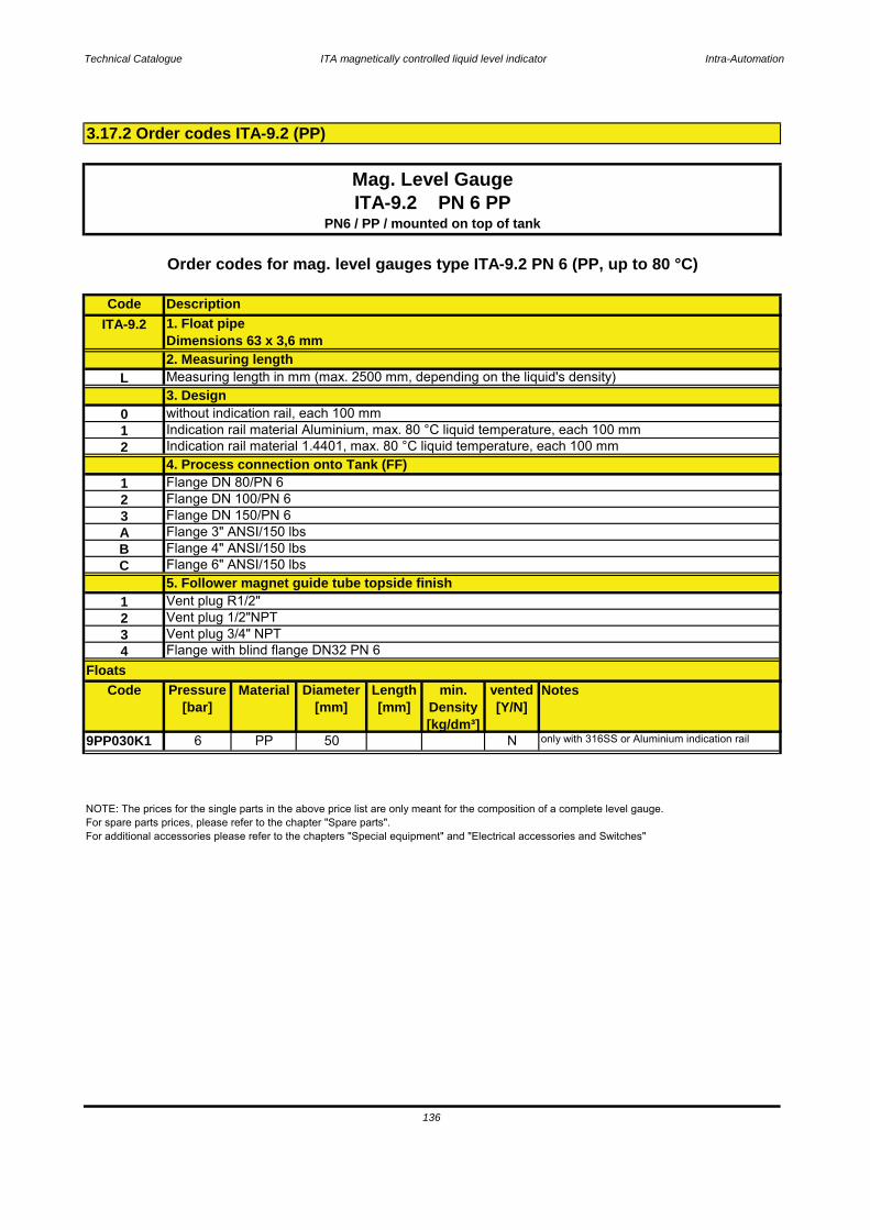
Technical Catalogue ITA magnetically controlled liquid level indicator Intra-Automation
CodeITA-9.2
L
012
123ABC
1234
Code Pressure[bar]
Material Diameter[mm]
Length[mm]
min. Density[kg/dm³]
vented[Y/N]
Notes
9PP030K1 6 PP 50 N only with 316SS or Aluminium indication rail
3.17.2 Order codes ITA-9.2 (PP)
136
Floats
NOTE: The prices for the single parts in the above price list are only meant for the composition of a complete level gauge.For spare parts prices, please refer to the chapter "Spare parts".For additional accessories please refer to the chapters "Special equipment" and "Electrical accessories and Switches"
Vent plug 1/2"NPTVent plug 3/4" NPTFlange with blind flange DN32 PN 6
Flange DN 150/PN 6Flange 3" ANSI/150 lbsFlange 4" ANSI/150 lbs
Indication rail material 1.4401, max. 80 °C liquid temperature, each 100 mm
3. Designwithout indication rail, each 100 mmIndication rail material Aluminium, max. 80 °C liquid temperature, each 100 mm
Vent plug R1/2"
4. Process connection onto Tank (FF)Flange DN 80/PN 6Flange DN 100/PN 6
Flange 6" ANSI/150 lbs5. Follower magnet guide tube topside finish
Mag. Level GaugeITA-9.2 PN 6 PP
PN6 / PP / mounted on top of tank
Measuring length in mm (max. 2500 mm, depending on the liquid's density)
Order codes for mag. level gauges type ITA-9.2 PN 6 (PP, up to 80 °C)
Description1. Float pipeDimensions 63 x 3,6 mm2. Measuring length

Technical Catalogue ITA magnetically controlled liquid level indicator Intra-Automation
ITA-9.2
6. Float
137
3.17.2 Order scheme for ITA-9.2
1. Type of level gauge [ITA-9.2]2. Measuring length in mm [or inches]
3. Design [Indication rail]4. Process connection on the tank [FF]
5. Follower magnet guide tube topside finish

Technical Catalogue ITA magnetically controlled liquid level indicator Intra-Automation
Key:1 Float pipe PVDF, dimensions 63 x 3 mm2 Measuring length3 Design (indication rail)4 Process connection on tank5 Follower magnet guide tube topside finish
3.18.1 ITA-9.3 [PVDF]
Characteristics: PN6 / Material: PVDF(mounted from top of tank)
138

Technical Catalogue ITA magnetically controlled liquid level indicator Intra-Automation
Base equipment printed in bold letters!
139
- (special sizes available)
Viscosity: max. 5000 mPa s
Float types: Cylindical, sealed type, with rodLength: - 250 mm
Indication rail: Aluminium1.4301
Gasket Viton
Operation density: min. 0,7 kg/dm³(depending on the measuring length)
Bolts & Nuts: SS
Operation pressure: max. 6 bar
Float material: PVDFOperation temperature: -40..+120 °C
Flange material: same as pipe material
Drain/Vent connections: Flanged DN32 PN6Pipe material: PVDF
Process connection: Flanged DN 80 (3")Flanged DN100…DN150 (4"…6")
Pipe diameter: 63 x 3 mm
Measuring range: max. 2500 mm
Mounting position: top of tank
Technical specifications magnetic level gauge type ITA-9.3
Principle: Communicating tubes with magnetic float

Technical Catalogue ITA magnetically controlled liquid level indicator Intra-Automation
CodeITA-9.3
L
012
123ABC
1234
Code Pressure[bar]
Material Diameter[mm]
Length[mm]
min. Density[kg/dm³]
vented[Y/N]
Notes
9PVD03K 6 PVDF 50 N only with 316SS or Aluminium indication rail
3.18.2 Order codes ITA-9.3 (PVDF)
140
Floats
NOTE: The prices for the single parts in the above price list are only meant for the composition of a complete level gauge.For spare parts prices, please refer to the chapter "Spare parts".For additional accessories please refer to the chapters "Special equipment" and "Electrical accessories and Switches"
Vent plug 1/2"NPTVent plug 3/4" NPTFlange with blind flange DN32 PN 6
Flange DN 150/PN 6Flange 3" ANSI/150 lbsFlange 4" ANSI/150 lbs
Indication rail material 1.4401, max. 120 °C liquid temperature, each 100 mm
3. Designwithout indication rail, each 100 mmIndication rail material Aluminium, max. 120 °C liquid temperature, each 100 mm
Vent plug R1/2"
4. Process connection onto tank (FF)Flange DN 80/PN 6Flange DN 100/PN 6
Flange 6" ANSI/150 lbs5. Follower magnet guide tube topside finish
Mag. Level GaugeITA-9.3 PN 6 PVDF
PN6 / PP / mounted on top of tank
Measuring length in mm (max. 2500 mm, depending on the liquid's density)
Order codes for mag. level gauge type ITA-9.3 PN 6 (PVDF, up to 120 °C)
Description1. Float PipeDimensions 63 x 3 mm2. Measuring length
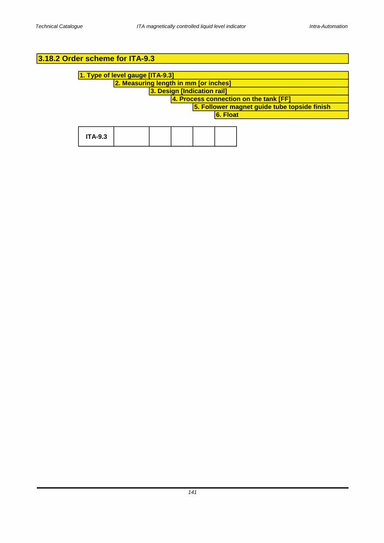
Technical Catalogue ITA magnetically controlled liquid level indicator Intra-Automation
ITA-9.3
6. Float
141
3.18.2 Order scheme for ITA-9.3
1. Type of level gauge [ITA-9.3]2. Measuring length in mm [or inches]
3. Design [Indication rail]4. Process connection on the tank [FF]
5. Follower magnet guide tube topside finish
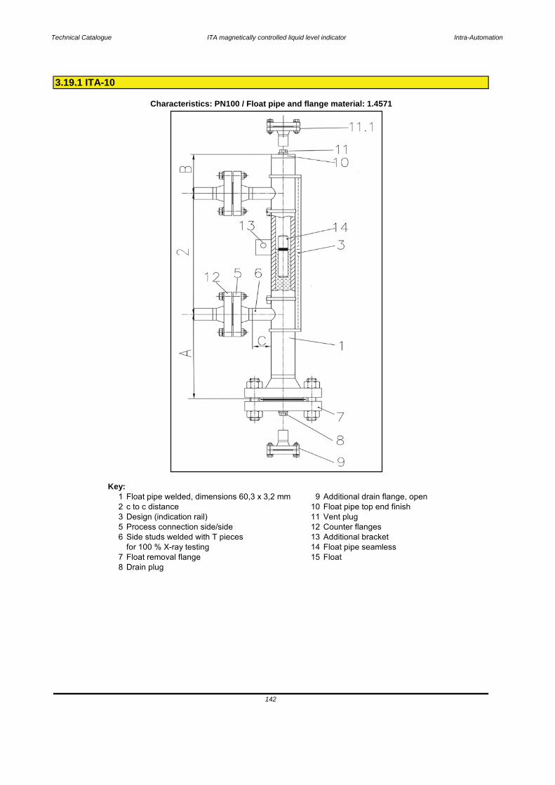
Technical Catalogue ITA magnetically controlled liquid level indicator Intra-Automation
Key:1 Float pipe welded, dimensions 60,3 x 3,2 mm 9 Additional drain flange, open2 c to c distance 10 Float pipe top end finish3 Design (indication rail) 11 Vent plug5 Process connection side/side 12 Counter flanges6 Side studs welded with T pieces 13 Additional bracket
for 100 % X-ray testing 14 Float pipe seamless7 Float removal flange 15 Float8 Drain plug
3.19.1 ITA-10
Characteristics: PN100 / Float pipe and flange material: 1.4571
142
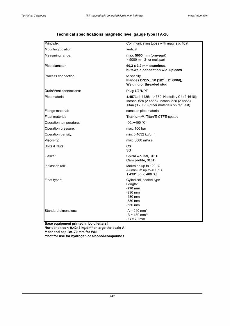
Technical Catalogue ITA magnetically controlled liquid level indicator Intra-Automation
-430 mm
Base equipment printed in bold letters!*for densities < 0,4243 kg/dm³ enlarge the scale A** for end cap B=170 mm for WN**not for use for hydrogen or alcohol-compounds
143
Standard dimensions: -A = 240 mm*-B = 130 mm**- C = 70 mm
-530 mm-630 mm
Length: -270 mm-330 mm
1.4301 up to 400 °C
Float types: Cylindical, sealed type
Indication rail: Makrolon up to 120 °CAluminium up to 400 °C
SS
Gasket Spiral wound, 316TiCam profile, 316Ti
Operation density: min. 0,4632 kg/dm³
Bolts & Nuts: CSViscosity: max. 5000 mPa s
Operation pressure: max. 100 bar
Float material: Titanium***, Titan/E-CTFE-coated
Operation temperature: -50..+400 °C
Flange material: same as pipe material
Pipe material: 1.4571; 1.4435; 1.4539; Hastelloy C4 (2.4610); Inconel 625 (2.4856); Inconel 825 (2.4858);Titan (3.7035) (other materials on request)
Drain/Vent connections: Plug 1/2"NPT
Process connection: to specify:Flanges DN15…50 (1/2"…2" 600#),Welding or threaded stud
Pipe diameter: 60,3 x 3,2 mm seamless,butt-weld connection wie T-pieces
Measuring range: max. 5000 mm (one-part)> 5000 mm 2- or multipart
Mounting position: vertical
Technical specifications magnetic level gauge type ITA-10
Principle: Communicating tubes with magnetic float
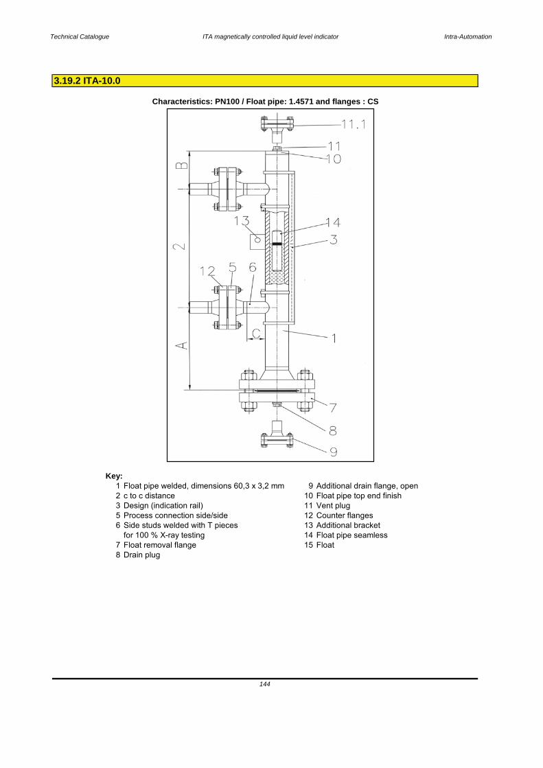
Technical Catalogue ITA magnetically controlled liquid level indicator Intra-Automation
Key:1 Float pipe welded, dimensions 60,3 x 3,2 mm 9 Additional drain flange, open2 c to c distance 10 Float pipe top end finish3 Design (indication rail) 11 Vent plug5 Process connection side/side 12 Counter flanges6 Side studs welded with T pieces 13 Additional bracket
for 100 % X-ray testing 14 Float pipe seamless7 Float removal flange 15 Float8 Drain plug
3.19.2 ITA-10.0
Characteristics: PN100 / Float pipe: 1.4571 and flanges : CS
144
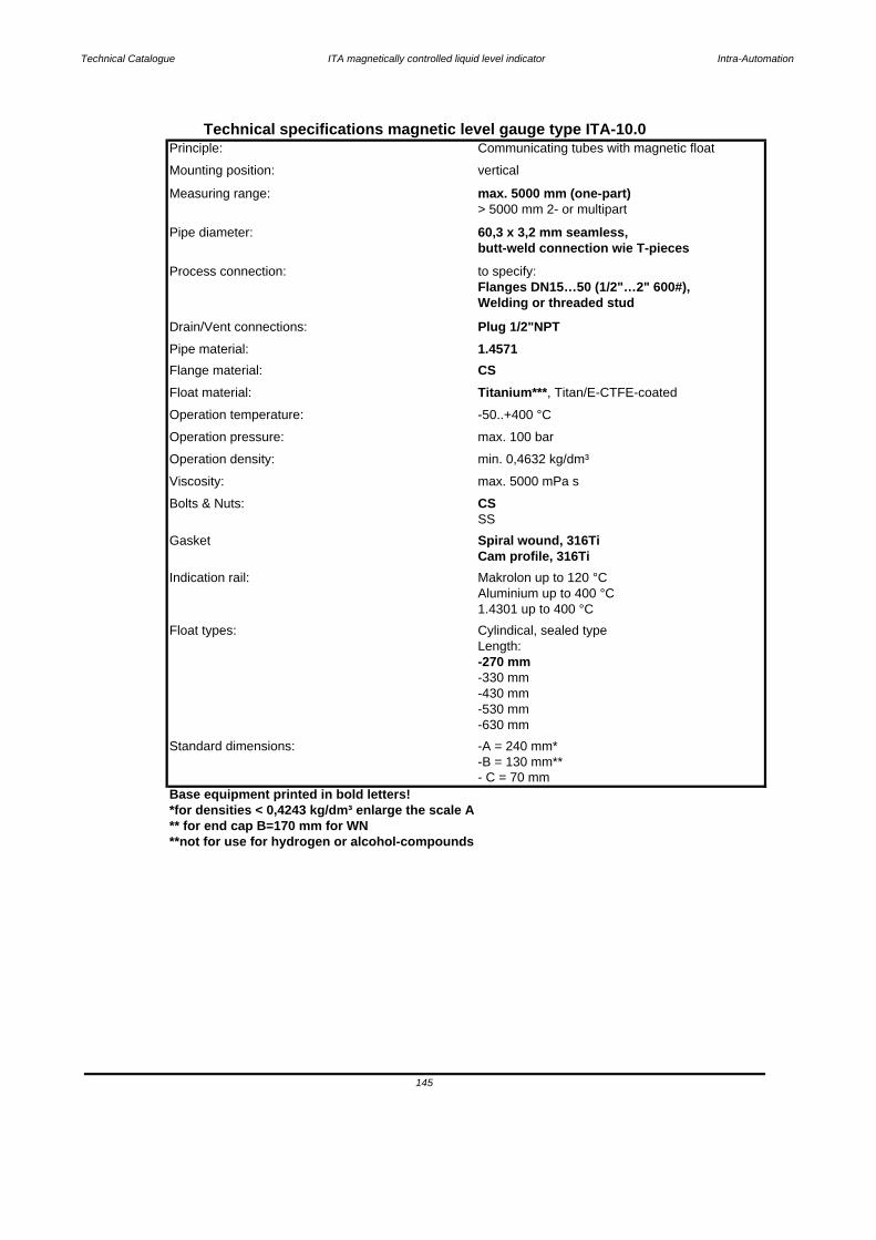
Technical Catalogue ITA magnetically controlled liquid level indicator Intra-Automation
-430 mm
Base equipment printed in bold letters!*for densities < 0,4243 kg/dm³ enlarge the scale A** for end cap B=170 mm for WN**not for use for hydrogen or alcohol-compounds
Technical specifications magnetic level gauge type ITA-10.0Principle: Communicating tubes with magnetic float
Mounting position: vertical
Measuring range: max. 5000 mm (one-part)> 5000 mm 2- or multipart
Pipe diameter: 60,3 x 3,2 mm seamless,butt-weld connection wie T-pieces
Process connection: to specify:Flanges DN15…50 (1/2"…2" 600#),Welding or threaded stud
Drain/Vent connections: Plug 1/2"NPTPipe material: 1.4571Flange material: CS
-50..+400 °C
Float material: Titanium***, Titan/E-CTFE-coated
Bolts & Nuts: CSSS
Operation density: min. 0,4632 kg/dm³
Viscosity: max. 5000 mPa s
Gasket Spiral wound, 316TiCam profile, 316Ti
Indication rail: Makrolon up to 120 °CAluminium up to 400 °C1.4301 up to 400 °C
Float types: Cylindical, sealed type
-630 mm
-330 mm
Length: -270 mm
-B = 130 mm**- C = 70 mm
Standard dimensions:
Operation pressure: max. 100 bar
Operation temperature:
145
-A = 240 mm*
-530 mm
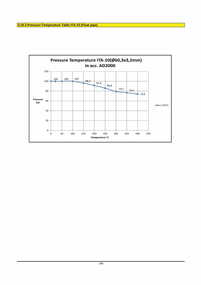
3.19.3 Pressure-Temperature Table ITA-10 (Float pipe)
146
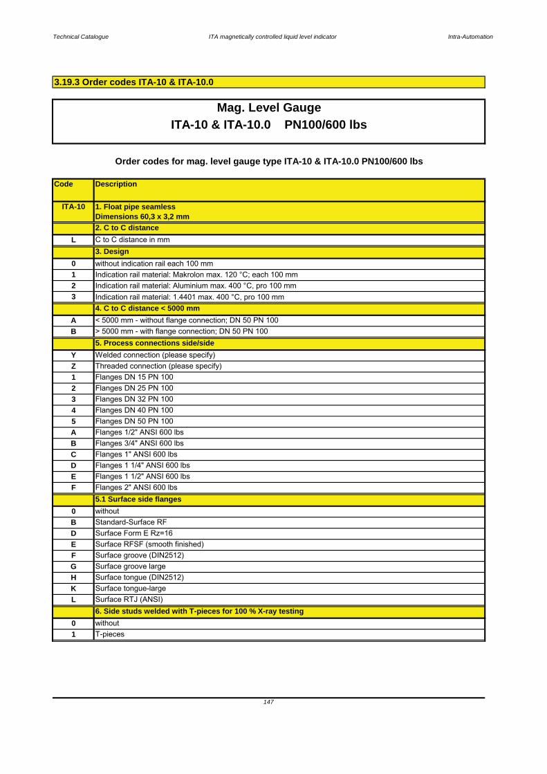
Technical Catalogue ITA magnetically controlled liquid level indicator Intra-Automation
Code Description
3.19.3 Order codes ITA-10 & ITA-10.0
147
Mag. Level GaugeITA-10 & ITA-10.0 PN100/600 lbs
B Standard-Surface RFD Surface Form E Rz=16E Surface RFSF (smooth finished)
6. Side studs welded with T-pieces for 100 % X-ray testing0 without1 T-pieces
K Surface tongue-largeL Surface RTJ (ANSI)
G Surface groove largeH Surface tongue (DIN2512)
F Surface groove (DIN2512)
E Flanges 1 1/2" ANSI 600 lbsF Flanges 2" ANSI 600 lbs
5.1 Surface side flanges0 without
C Flanges 1" ANSI 600 lbsD Flanges 1 1/4" ANSI 600 lbs
A Flanges 1/2" ANSI 600 lbs B Flanges 3/4" ANSI 600 lbs
4 Flanges DN 40 PN 1005 Flanges DN 50 PN 100
2 Flanges DN 25 PN 1003 Flanges DN 32 PN 100
1 Flanges DN 15 PN 100
5. Process connections side/sideY Welded connection (please specify)
3 Indication rail material: 1.4401 max. 400 °C, pro 100 mm4. C to C distance < 5000 mm
Z Threaded connection (please specify)
Order codes for mag. level gauge type ITA-10 & ITA-10.0 PN100/600 lbs
ITA-10 1. Float pipe seamless Dimensions 60,3 x 3,2 mm2. C to C distance
0 without indication rail each 100 mm
L C to C distance in mm
1 Indication rail material: Makrolon max. 120 °C; each 100 mm2 Indication rail material: Aluminium max. 400 °C, pro 100 mm
A < 5000 mm - without flange connection; DN 50 PN 100B > 5000 mm - with flange connection; DN 50 PN 100
3. Design

Technical Catalogue ITA magnetically controlled liquid level indicator Intra-Automation
Code Description
Drain stud with flange 1 1/2" ANSI 600 lbs
148
Mag. Level Gauge
F Surface groove (DIN2512)
H Surface tongue (DIN2512)
B Drain stud with flange 3/4" ANSI 600 lbsC Drain stud with flange 1" ANSI 600 lbs
Drain stud with flange 1 1/4" ANSI 600 lbsED
4 Drain stud with flange DN 40 PN 100A Drain stud with flange 1/2" ANSI 600 lbs
2 Drain stud with flange DN 25 PN 1003 Drain stud with flange DN 32 PN 100
4 Drain plug 1" NPT
without9. Additional drain flange, open
0
Drain plug G 1/2" with soft iron gasket
3 Drain plug 3/4" NPT
M24 x 120 mm; mat. PTFE-coated; Flange 2510 DN50 PN 100FA 5/8" x 108 mm; RF; mat. A193B7/A1942H zinced steel; flange 2" ANSI 600 lbs, ANSI B16.5FB 5/8" x 108 mm; RF; mat. A193B8 / A1948M SS; flange 2" ANSI 600 lbs, ANSI B16.5
0
7.2 Bolts & Nuts float removal flange
61 M24 x 120 mm; mat. steel zinced; Flange DN 50 PN 10062 M24 x 120 mm; mat. SS 1.4301; Flange DN 50 PN 10063
L Surface RTJ (ANSI) K
G Surface groove large
4 Flange 2" ANSI 600 lbs prepared for shut off valve on side
1 Flange DN 50 PN 100 incl. blind flange
Order codes for mag. level gauge type ITA-10 & ITA-10.0 PN100/600 lbs
Surface tongue-large
2 Flange 2" ANSI 600 lbs incl. blind flange3
D Surface Form E Rz=16
Flange DN 50 PN 100 prepared for shut off valve on side
E Surface RFSF (smooth finished)
7.1 Surface float removal flange (bottom side) (only DN50 or 2")B Standard-Surface RF
7. Float removal flange (bottom side)
ITA-10 & ITA-10.0 PN100/600 lbs
0 without (Float removal flange (bottom side) = end cap)
FD 5/8" x 108 mm; RTJ; mat. A193B8 / A1948M SS; flange 2" ANSI 600 lbs, ANSI B16.5FT 5/8" x 108 mm; RF; mat. A193B8 / A1948M PTFE-coated; flange 2" ANSI 600 lbs, ANSI B16.5
without1
1 Drain stud with flange DN 15 PN 100
FC 5/8" x 108 mm; RTJ; mat. A193B7/A1942H zinced steel, flange 2" ANSI 600 lbs; ANSI B16.5
5/8" x 108 mm; RTJ; mat. A193B8/A1948M PTFE-coated, flange 2" ANSI 600 lbs; ANSI B16.5
2 Drain plug 1/2" NPT
8. Drain plugFV
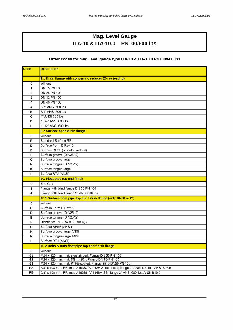
Technical Catalogue ITA magnetically controlled liquid level indicator Intra-Automation
Code Description
149
Mag. Level GaugeITA-10 & ITA-10.0 PN100/600 lbs
62
FB
63 M24 x 120 mm; mat. PTFE-coated; Flange 2510 DN50 PN 100FA 5/8" x 108 mm; RF; mat. A193B7/A1942H zinced steel; flange 2" ANSI 600 lbs, ANSI B16.5
L Surface RTJ (ANSI) 10.2 Bolts & nuts float pipe top end finish flange
0 without
K Surface tongue-large ANSI
F Dichtleiste RF - RA = 3,2 bis 6,3G Surface RFSF (ANSI)H Surface groove large ANSI
B Surface Form E Rz=16
E Surface tongue (DIN2512)D Surface groove (DIN2512)
01 Flange with blind flange DN 50 PN 100
End Cap 10. Float pipe top end finish
L
F Surface groove (DIN2512)
0 without10.1 Surface float pipe top end finish flange (only DN50 or 2")
Surface RTJ (ANSI)
A Flange with blind flange 2" ANSI 600 lbs
D Surface Form E Rz=16E Surface RFSF (smooth finished)
K Surface tongue-largeH Surface tongue (DIN2512)G Surface groove large
B Standard-Surface RF
E 1 1/2" ANSI 600 lbs9.2 Surface open drain flange
0 without
A
C 1" ANSI 600 lbsD
B 3/4" ANSI 600 lbs
1 1/4" ANSI 600 lbs
1/2" ANSI 600 lbs 4 DN 40 PN 100
2 DN 25 PN 1001 DN 15 PN 100
9.1 Drain flange with concentric reducer (X-ray testing)
Order codes for mag. level gauge type ITA-10 & ITA-10.0 PN100/600 lbs
without
3 DN 32 PN 100
0
5/8" x 108 mm; RF; mat. A193B8 / A1948M SS; flange 2" ANSI 600 lbs, ANSI B16.5
M24 x 120 mm; mat. SS 1.4301; Flange DN 50 PN 10061 M24 x 120 mm; mat. steel zinced; Flange DN 50 PN 100
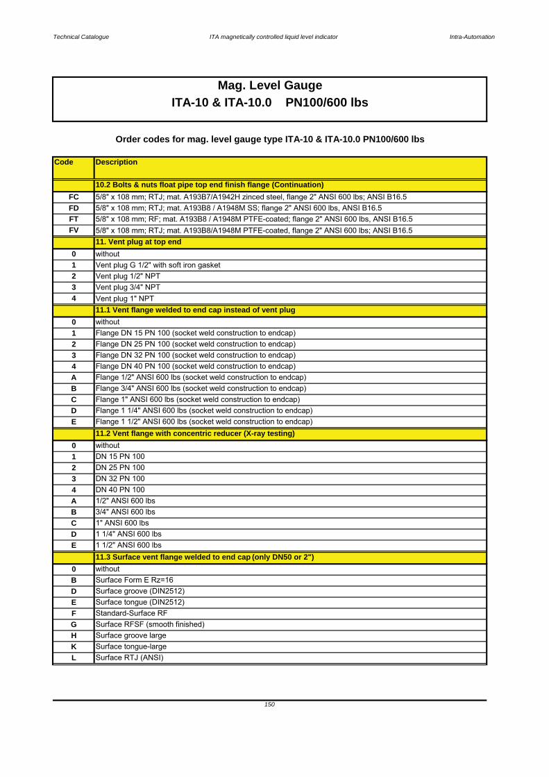
Technical Catalogue ITA magnetically controlled liquid level indicator Intra-Automation
Code Description
without Flange DN 15 PN 100 (socket weld construction to endcap)Flange DN 25 PN 100 (socket weld construction to endcap)Flange DN 32 PN 100 (socket weld construction to endcap)Flange DN 40 PN 100 (socket weld construction to endcap)Flange 1/2" ANSI 600 lbs (socket weld construction to endcap)Flange 3/4" ANSI 600 lbs (socket weld construction to endcap)Flange 1" ANSI 600 lbs (socket weld construction to endcap)Flange 1 1/4" ANSI 600 lbs (socket weld construction to endcap)Flange 1 1/2" ANSI 600 lbs (socket weld construction to endcap)
withoutDN 15 PN 100DN 25 PN 100DN 32 PN 100DN 40 PN 1001/2" ANSI 600 lbs 3/4" ANSI 600 lbs1" ANSI 600 lbs1 1/4" ANSI 600 lbs
withoutSurface Form E Rz=16Surface groove (DIN2512)Surface tongue (DIN2512)Standard-Surface RFSurface RFSF (smooth finished)Surface groove largeSurface tongue-largeSurface RTJ (ANSI)
150
10.2 Bolts & nuts float pipe top end finish flange (Continuation)
Mag. Level GaugeITA-10 & ITA-10.0 PN100/600 lbs
Order codes for mag. level gauge type ITA-10 & ITA-10.0 PN100/600 lbs
34
11.2 Vent flange with concentric reducer (X-ray testing)012
BC
DC
B
FG
ED
E 1 1/2" ANSI 600 lbs
AB
LKH
11.3 Surface vent flange welded to end cap (only DN50 or 2")0
DE
without
A4
11.1 Vent flange welded to end cap instead of vent plug0123
Vent plug 1/2" NPT
4 Vent plug 1" NPT3 Vent plug 3/4" NPT
FT 5/8" x 108 mm; RF; mat. A193B8 / A1948M PTFE-coated; flange 2" ANSI 600 lbs, ANSI B16.5
1 Vent plug G 1/2" with soft iron gasket2
FD 5/8" x 108 mm; RTJ; mat. A193B8 / A1948M SS; flange 2" ANSI 600 lbs, ANSI B16.5
11. Vent plug at top end0
FV 5/8" x 108 mm; RTJ; mat. A193B8/A1948M PTFE-coated, flange 2" ANSI 600 lbs; ANSI B16.5
FC 5/8" x 108 mm; RTJ; mat. A193B7/A1942H zinced steel, flange 2" ANSI 600 lbs; ANSI B16.5
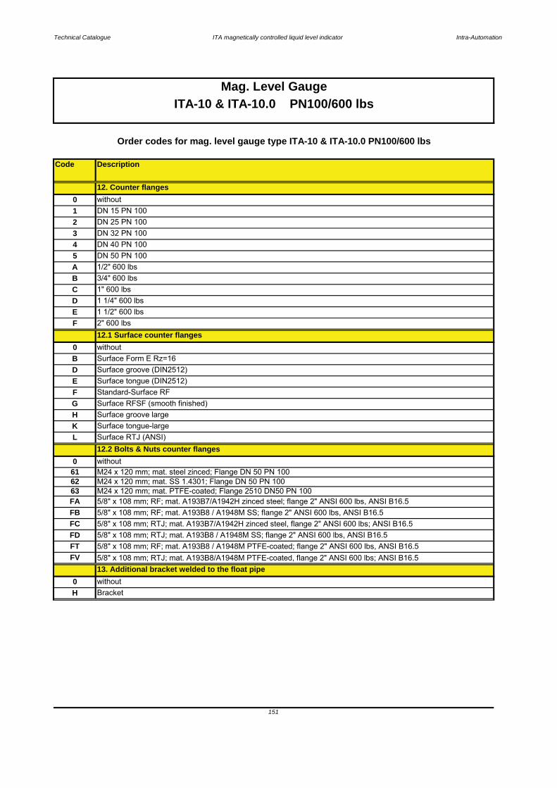
Technical Catalogue ITA magnetically controlled liquid level indicator Intra-Automation
Code Description
withoutSurface Form E Rz=16Surface groove (DIN2512)Surface tongue (DIN2512)Standard-Surface RFSurface RFSF (smooth finished)Surface groove largeSurface tongue-largeSurface RTJ (ANSI)
without
Order codes for mag. level gauge type ITA-10 & ITA-10.0 PN100/600 lbs
151
Mag. Level GaugeITA-10 & ITA-10.0 PN100/600 lbs
62 M24 x 120 mm; mat. SS 1.4301; Flange DN 50 PN 100
12.2 Bolts & Nuts counter flanges
61 M24 x 120 mm; mat. steel zinced; Flange DN 50 PN 1000
KL
G
H Bracket
13. Additional bracket welded to the float pipe0 without
2" 600 lbs12.1 Surface counter flanges
0
F
H
F
BDE
DN 50 PN 100
D 1 1/4" 600 lbsE 1 1/2" 600 lbs
B 3/4" 600 lbsC 1" 600 lbs
1 DN 15 PN 1002
A 1/2" 600 lbs
3 DN 32 PN 1004 DN 40 PN 1005
DN 25 PN 100
0 without12. Counter flanges
FB 5/8" x 108 mm; RF; mat. A193B8 / A1948M SS; flange 2" ANSI 600 lbs, ANSI B16.5FC 5/8" x 108 mm; RTJ; mat. A193B7/A1942H zinced steel, flange 2" ANSI 600 lbs; ANSI B16.5
63 M24 x 120 mm; mat. PTFE-coated; Flange 2510 DN50 PN 100FA 5/8" x 108 mm; RF; mat. A193B7/A1942H zinced steel; flange 2" ANSI 600 lbs, ANSI B16.5
FV 5/8" x 108 mm; RTJ; mat. A193B8/A1948M PTFE-coated, flange 2" ANSI 600 lbs; ANSI B16.5
FD 5/8" x 108 mm; RTJ; mat. A193B8 / A1948M SS; flange 2" ANSI 600 lbs, ANSI B16.5FT 5/8" x 108 mm; RF; mat. A193B8 / A1948M PTFE-coated; flange 2" ANSI 600 lbs, ANSI B16.5
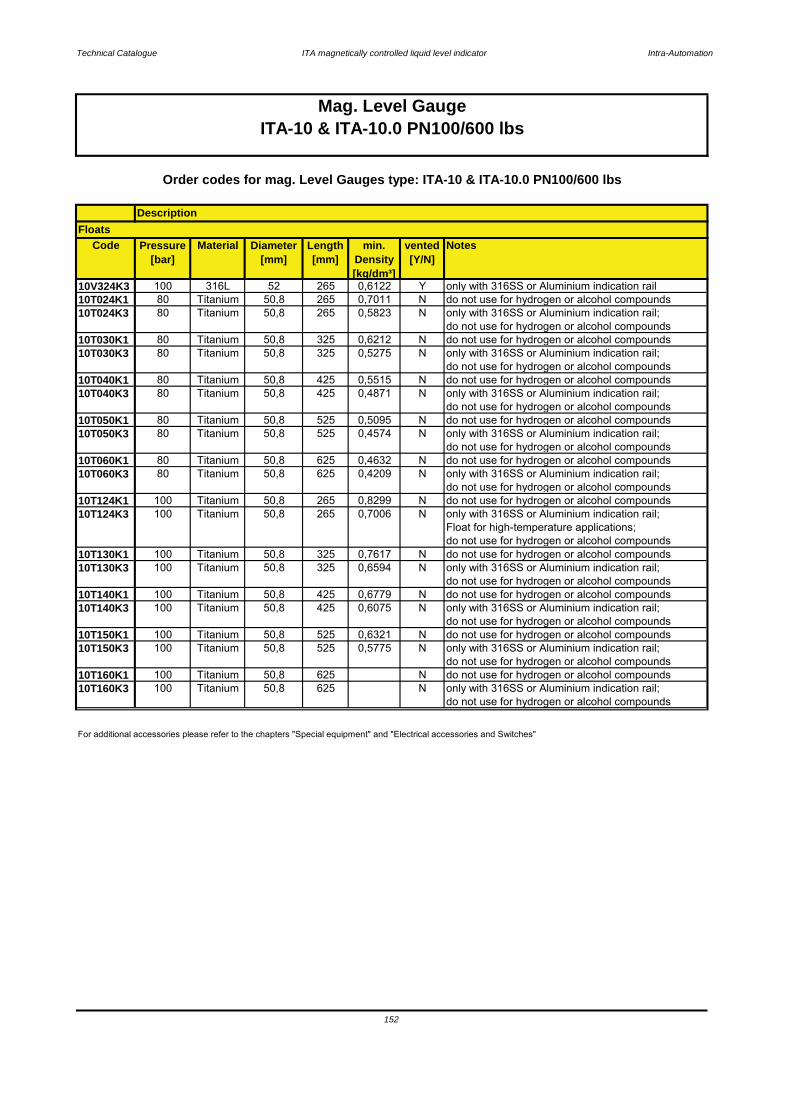
Technical Catalogue ITA magnetically controlled liquid level indicator Intra-Automation
Code Pressure[bar]
Material Diameter[mm]
Length[mm]
min. Density[kg/dm³]
vented[Y/N]
Notes
10V324K3 100 316L 52 265 0,6122 Y only with 316SS or Aluminium indication rail10T024K1 80 Titanium 50,8 265 0,7011 N do not use for hydrogen or alcohol compounds10T024K3 80 Titanium 50,8 265 0,5823 N only with 316SS or Aluminium indication rail;
do not use for hydrogen or alcohol compounds10T030K1 80 Titanium 50,8 325 0,6212 N do not use for hydrogen or alcohol compounds10T030K3 80 Titanium 50,8 325 0,5275 N only with 316SS or Aluminium indication rail;
do not use for hydrogen or alcohol compounds10T040K1 80 Titanium 50,8 425 0,5515 N do not use for hydrogen or alcohol compounds10T040K3 80 Titanium 50,8 425 0,4871 N only with 316SS or Aluminium indication rail;
do not use for hydrogen or alcohol compounds10T050K1 80 Titanium 50,8 525 0,5095 N do not use for hydrogen or alcohol compounds10T050K3 80 Titanium 50,8 525 0,4574 N only with 316SS or Aluminium indication rail;
do not use for hydrogen or alcohol compounds10T060K1 80 Titanium 50,8 625 0,4632 N do not use for hydrogen or alcohol compounds10T060K3 80 Titanium 50,8 625 0,4209 N only with 316SS or Aluminium indication rail;
do not use for hydrogen or alcohol compounds10T124K1 100 Titanium 50,8 265 0,8299 N do not use for hydrogen or alcohol compounds10T124K3 100 Titanium 50,8 265 0,7006 N only with 316SS or Aluminium indication rail;
Float for high-temperature applications;do not use for hydrogen or alcohol compounds
10T130K1 100 Titanium 50,8 325 0,7617 N do not use for hydrogen or alcohol compounds10T130K3 100 Titanium 50,8 325 0,6594 N only with 316SS or Aluminium indication rail;
do not use for hydrogen or alcohol compounds10T140K1 100 Titanium 50,8 425 0,6779 N do not use for hydrogen or alcohol compounds10T140K3 100 Titanium 50,8 425 0,6075 N only with 316SS or Aluminium indication rail;
do not use for hydrogen or alcohol compounds10T150K1 100 Titanium 50,8 525 0,6321 N do not use for hydrogen or alcohol compounds10T150K3 100 Titanium 50,8 525 0,5775 N only with 316SS or Aluminium indication rail;
do not use for hydrogen or alcohol compounds10T160K1 100 Titanium 50,8 625 N do not use for hydrogen or alcohol compounds10T160K3 100 Titanium 50,8 625 N only with 316SS or Aluminium indication rail;
do not use for hydrogen or alcohol compounds
152
Mag. Level GaugeITA-10 & ITA-10.0 PN100/600 lbs
For additional accessories please refer to the chapters "Special equipment" and "Electrical accessories and Switches"
Order codes for mag. Level Gauges type: ITA-10 & ITA-10.0 PN100/600 lbs
DescriptionFloats

Technical Catalogue ITA magnetically controlled liquid level indicator Intra-Automation
153
12.1 Surface counter flanges12.2 Bolts & nuts counter flanges
13. Additional bracket welded to the float pipe14. Float
10.2 Bolts and nuts rop end finish flange11. Vent plug at top end
11.1 Vent flange welded to end cap instead of vent plug11.2 Vent flange with concentric reducer (X-ray testing)
11.3 Surface vent flange welded to end cap 12. Counter flanges
ITA-10.0
9.1 Drain flange with concentric reducer (X-ray testing)9.2 Surface open drain flange
10. Float pipe top end finish10.1 Surface top end finish flange
9. Additional drain flange, open
ITA-10
7.2 Bolts & nuts float removal flange8. Drain plug
7. Float removal flange7.1 Surface float removal flange
5.1 Surface side flanges6. Side studs welded with T-pieces for 100 % X-ray-testing
4. C to C distance > 5000 mm5. Process connection [side/side]
3.19.4 Order code scheme for ITA-10 & ITA-10.0
1. Type of level gauge ITA-10 or ITA-10.02. C to C distance in mm [or inches]
3. Design

Technical Catalogue ITA magnetically controlled liquid level indicator Intra-Automation
Key:1 Float pipe welded, dimensions 60,3 x 3,91 mm 9 Additional drain flange, open2 c to c distance 10 Float pipe top end finish3 Design (indication rail) 11 Vent plug5 Process connection side/side 12 Counter flanges6 Side studs welded with T pieces 13 Additional bracket
for 100 % X-ray testing 14 Float pipe seamless7 Float removal flange 15 Float8 Drain plug
3.20.1 ITA-11
Characteristics: PN160 / Float pipe and flange material: 1.4571
154
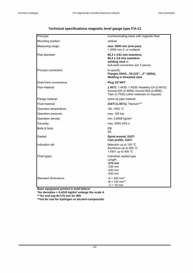
Technical Catalogue ITA magnetically controlled liquid level indicator Intra-Automation
-430 mm
Base equipment printed in bold letters!*for densities < 0,4243 kg/dm³ enlarge the scale A** for end cap B=170 mm for WN**not for use for hydrogen or alcohol-compounds
Viscosity: max. 5000 mPa s
60,3 x 3,6 mm seamlesswelding stud or
- C = 70 mm
155
-330 mm
-530 mmStandard dimensions: -A = 240 mm*
-B = 130 mm**
Length: -270 mm
1.4301 up to 400 °CFloat types: Cylindical, sealed type
Indication rail: Makrolon up to 120 °CAluminium up to 400 °C
SSGasket Spiral wound, 316Ti
Cam profile, 316Ti
Operation density: min. 0,6008 kg/dm³
Bolts & Nuts: CS
Operation pressure: max. 160 bar
Float material: 316Ti (1.4571); Titanium***
Operation temperature: -50..+400 °C
Flange material: same as pipe material
Pipe material: 1.4571; 1.4435; 1.4539; Hastelloy C4 (2.4610); Inconel 625 (2.4856); Inconel 825 (2.4858);Titan (3.7035) (other materials on request)
Drain/Vent connections: Plug 1/2"NPT
Process connection: to specify:Flanges DN15…50 (1/2"…2" 1500#),Welding or threaded stud
Pipe diameter: 60,3 x 3,91 mm seamless,
butt-weld connection wie T-pieces
Measuring range: max. 5000 mm (one-part)> 5000 mm 2- or multipart
Mounting position: vertical
Technical specifications magnetic level gauge type ITA-11
Principle: Communicating tubes with magnetic float

Technical Catalogue ITA magnetically controlled liquid level indicator Intra-Automation
Key:1 Float pipe welded, dimensions 60,3 x 3,91 mm 9 Additional drain flange, open2 c to c distance 10 Float pipe top end finish3 Design (indication rail) 11 Vent plug5 Process connection side/side 12 Counter flanges6 Side studs welded with T pieces 13 Additional bracket
for 100 % X-ray testing 14 Float pipe seamless7 Float removal flange 15 Float8 Drain plug
156
3.20.2 ITA-11.0
Characteristics: PN160 / Float pipe: 1.4571 and flanges : CS
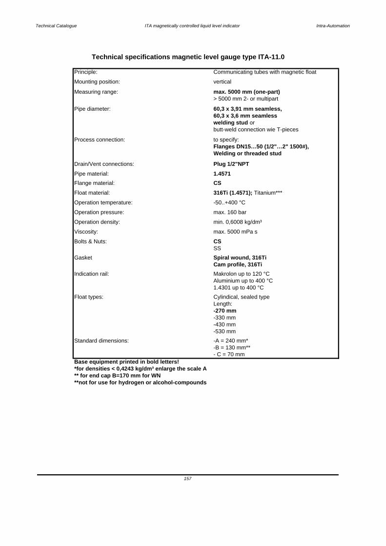
Technical Catalogue ITA magnetically controlled liquid level indicator Intra-Automation
-430 mm
Base equipment printed in bold letters!*for densities < 0,4243 kg/dm³ enlarge the scale A** for end cap B=170 mm for WN**not for use for hydrogen or alcohol-compounds
- C = 70 mm
Technical specifications magnetic level gauge type ITA-11.0
Principle: Communicating tubes with magnetic float
Mounting position: vertical
Measuring range: max. 5000 mm (one-part)> 5000 mm 2- or multipart
60,3 x 3,6 mm seamlesswelding stud or
Pipe diameter: 60,3 x 3,91 mm seamless,
butt-weld connection wie T-pieces
Process connection: to specify:Flanges DN15…50 (1/2"…2" 1500#),Welding or threaded stud
Drain/Vent connections: Plug 1/2"NPTPipe material: 1.4571 Flange material: CSFloat material: 316Ti (1.4571); Titanium***
Operation temperature: -50..+400 °C
SS
min. 0,6008 kg/dm³
Bolts & Nuts: CSViscosity: max. 5000 mPa s
Gasket Spiral wound, 316TiCam profile, 316Ti
Indication rail: Makrolon up to 120 °CAluminium up to 400 °C1.4301 up to 400 °C
Float types: Cylindical, sealed type
-270 mm-330 mm
Standard dimensions: -A = 240 mm*
-530 mm
157
Operation density:
Length:
-B = 130 mm**
Operation pressure: max. 160 bar
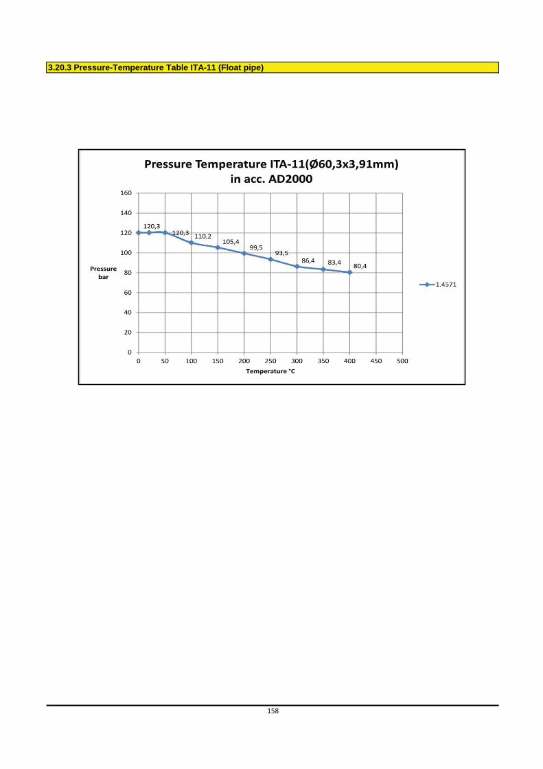
3.20.3 Pressure-Temperature Table ITA-11 (Float pipe)
158
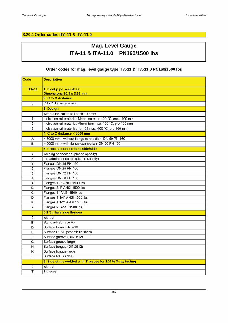
Technical Catalogue ITA magnetically controlled liquid level indicator Intra-Automation
Code Description
3.20.4 Order codes ITA-11 & ITA-11.0
159
L Surface RTJ (ANSI) 6. Side studs welded with T-pieces for 100 % X-ray testing
0 withoutT T-pieces
H Surface tongue (DIN2512)K Surface tongue-large
F Surface groove (DIN2512)G Surface groove large
D Surface Form E Rz=16E Surface RFSF (smooth finished)
0 withoutB Standard-Surface RF
F Flanges 2" ANSI 1500 lbs5.1 Surface side flanges
D Flanges 1 1/4" ANSI 1500 lbsE Flanges 1 1/2" ANSI 1500 lbs
B Flanges 3/4" ANSI 1500 lbsC Flanges 1" ANSI 1500 lbs
4 Flanges DN 50 PN 160A Flanges 1/2" ANSI 1500 lbs
2 Flanges DN 25 PN 1603 Flanges DN 32 PN 160
1 Flanges DN 15 PN 160
5. Process connections side/sideY welding connection (please specify)
1 Indication rail material: Makrolon max. 120 °C; each 100 mm
3 Indication rail material: 1.4401 max. 400 °C, pro 100 mm
Z threaded connection (please specify)
A < 5000 mm - without flange connection; DN 50 PN 160
2 Indication rail material: Aluminium max. 400 °C, pro 100 mm
B > 5000 mm - with flange connection; DN 50 PN 160
4. C to C distance < 5000 mm
0 without indication rail each 100 mm
L C to C distance in mm3. Design
2. C to C distance
Mag. Level GaugeITA-11 & ITA-11.0 PN160/1500 lbs
Order codes for mag. level gauge type ITA-11 & ITA-11.0 PN160/1500 lbs
ITA-11 1. Float pipe seamlessDimensions 60,3 x 3,91 mm
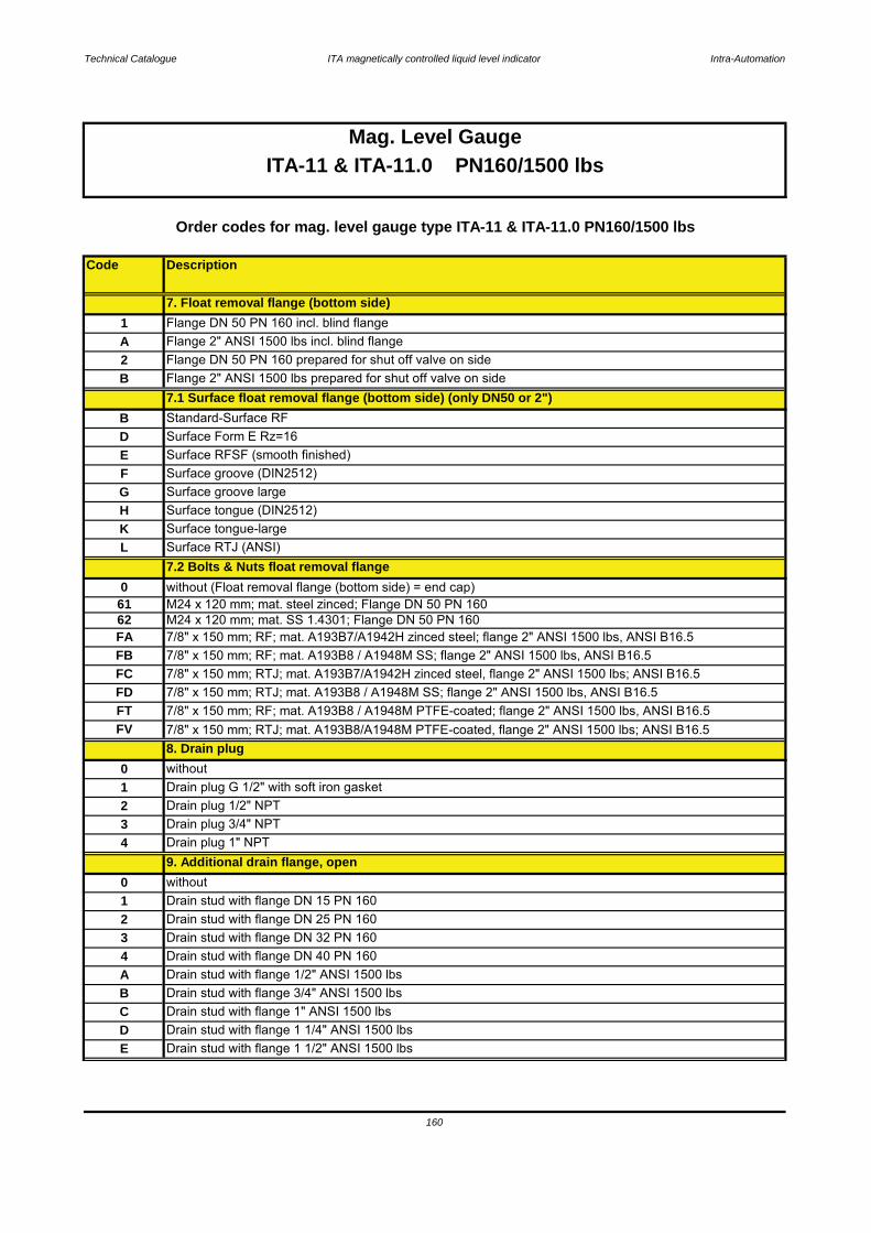
Technical Catalogue ITA magnetically controlled liquid level indicator Intra-Automation
Code Description
160
Mag. Level GaugeITA-11 & ITA-11.0 PN160/1500 lbs
Drain stud with flange 1 1/4" ANSI 1500 lbsE Drain stud with flange 1 1/2" ANSI 1500 lbs
A Drain stud with flange 1/2" ANSI 1500 lbs B Drain stud with flange 3/4" ANSI 1500 lbsC Drain stud with flange 1" ANSI 1500 lbsD
3 Drain stud with flange DN 32 PN 1604 Drain stud with flange DN 40 PN 160
2 Drain plug 1/2" NPT
1 Drain stud with flange DN 15 PN 1602 Drain stud with flange DN 25 PN 160
9. Additional drain flange, open0 without
L Surface RTJ (ANSI)
61
FB 7/8" x 150 mm; RF; mat. A193B8 / A1948M SS; flange 2" ANSI 1500 lbs, ANSI B16.5
without
7.2 Bolts & Nuts float removal flange0 without (Float removal flange (bottom side) = end cap)
FA 7/8" x 150 mm; RF; mat. A193B7/A1942H zinced steel; flange 2" ANSI 1500 lbs, ANSI B16.562
FT 7/8" x 150 mm; RF; mat. A193B8 / A1948M PTFE-coated; flange 2" ANSI 1500 lbs, ANSI B16.5
Order codes for mag. level gauge type ITA-11 & ITA-11.0 PN160/1500 lbs
E Surface RFSF (smooth finished)F Surface groove (DIN2512)
B Standard-Surface RFD Surface Form E Rz=16
Flange 2" ANSI 1500 lbs incl. blind flange2 Flange DN 50 PN 160 prepared for shut off valve on sideB Flange 2" ANSI 1500 lbs prepared for shut off valve on side
M24 x 120 mm; mat. SS 1.4301; Flange DN 50 PN 160M24 x 120 mm; mat. steel zinced; Flange DN 50 PN 160
K
7. Float removal flange (bottom side)
Surface tongue-large
G Surface groove largeH Surface tongue (DIN2512)
7.1 Surface float removal flange (bottom side) (only DN50 or 2")
A1 Flange DN 50 PN 160 incl. blind flange
FV 7/8" x 150 mm; RTJ; mat. A193B8/A1948M PTFE-coated, flange 2" ANSI 1500 lbs; ANSI B16.5
FC 7/8" x 150 mm; RTJ; mat. A193B7/A1942H zinced steel, flange 2" ANSI 1500 lbs; ANSI B16.5FD 7/8" x 150 mm; RTJ; mat. A193B8 / A1948M SS; flange 2" ANSI 1500 lbs, ANSI B16.5
8. Drain plug0
3 Drain plug 3/4" NPT4 Drain plug 1" NPT
1 Drain plug G 1/2" with soft iron gasket
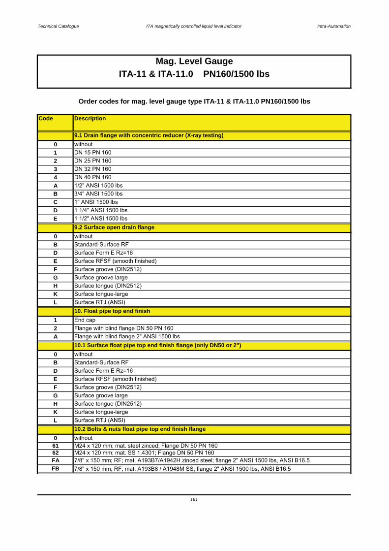
Technical Catalogue ITA magnetically controlled liquid level indicator Intra-Automation
Code Description
Mag. Level Gauge
161
A Flange with blind flange 2" ANSI 1500 lbs
L Surface RTJ (ANSI)
0 without
62 M24 x 120 mm; mat. SS 1.4301; Flange DN 50 PN 16061 M24 x 120 mm; mat. steel zinced; Flange DN 50 PN 160
10.2 Bolts & nuts float pipe top end finish flange
F Surface groove (DIN2512)G Surface groove largeH Surface tongue (DIN2512)K Surface tongue-large
10. Float pipe top end finish
E Surface RFSF (smooth finished)
0 without
D Surface Form E Rz=16B
B Standard-Surface RFD Surface Form E Rz=16E
Standard-Surface RF
10.1 Surface float pipe top end finish flange (only DN50 or 2")
Flange with blind flange DN 50 PN 1602
K Surface tongue-large
1 End cap
G Surface groove largeH Surface tongue (DIN2512)
L Surface RTJ (ANSI)
Surface RFSF (smooth finished)F Surface groove (DIN2512)
D 1 1/4" ANSI 1500 lbsE 1 1/2" ANSI 1500 lbs
9.2 Surface open drain flange0 without
4 DN 40 PN 160A 1/2" ANSI 1500 lbs B 3/4" ANSI 1500 lbsC 1" ANSI 1500 lbs
3 DN 32 PN 160
0 without1 DN 15 PN 1602 DN 25 PN 160
9.1 Drain flange with concentric reducer (X-ray testing)
ITA-11 & ITA-11.0 PN160/1500 lbs
Order codes for mag. level gauge type ITA-11 & ITA-11.0 PN160/1500 lbs
7/8" x 150 mm; RF; mat. A193B7/A1942H zinced steel; flange 2" ANSI 1500 lbs, ANSI B16.5FAFB 7/8" x 150 mm; RF; mat. A193B8 / A1948M SS; flange 2" ANSI 1500 lbs, ANSI B16.5
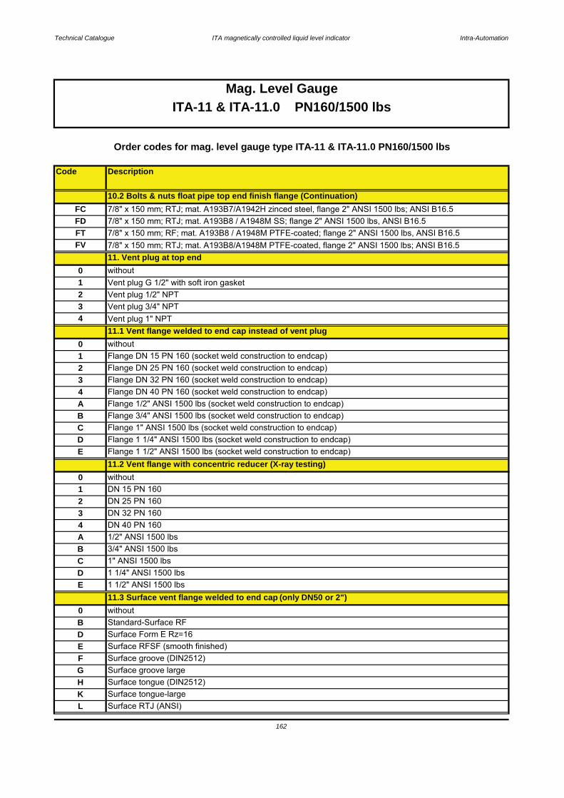
Technical Catalogue ITA magnetically controlled liquid level indicator Intra-Automation
Code Description
1 1/4" ANSI 1500 lbs
B 3/4" ANSI 1500 lbsC 1" ANSI 1500 lbs
162
10.2 Bolts & nuts float pipe top end finish flange (Continuation)
E 1 1/2" ANSI 1500 lbsD
K Surface tongue-largeL Surface RTJ (ANSI)
G Surface groove largeH Surface tongue (DIN2512)
E Surface RFSF (smooth finished)F Surface groove (DIN2512)
0 without11.3 Surface vent flange welded to end cap (only DN50 or 2")
D Surface Form E Rz=16B Standard-Surface RF
A 1/2" ANSI 1500 lbs
3 DN 32 PN 160
without1 DN 15 PN 1602 DN 25 PN 160
0
E Flange 1 1/2" ANSI 1500 lbs (socket weld construction to endcap)11.2 Vent flange with concentric reducer (X-ray testing)
4 DN 40 PN 160
C Flange 1" ANSI 1500 lbs (socket weld construction to endcap)D Flange 1 1/4" ANSI 1500 lbs (socket weld construction to endcap)
A Flange 1/2" ANSI 1500 lbs (socket weld construction to endcap)B Flange 3/4" ANSI 1500 lbs (socket weld construction to endcap)
3 Flange DN 32 PN 160 (socket weld construction to endcap)4 Flange DN 40 PN 160 (socket weld construction to endcap)
1 Flange DN 15 PN 160 (socket weld construction to endcap)2 Flange DN 25 PN 160 (socket weld construction to endcap)
11.1 Vent flange welded to end cap instead of vent plug0 without
3 Vent plug 3/4" NPT4 Vent plug 1" NPT
11. Vent plug at top end
FC 7/8" x 150 mm; RTJ; mat. A193B7/A1942H zinced steel, flange 2" ANSI 1500 lbs; ANSI B16.5
Mag. Level GaugeITA-11 & ITA-11.0 PN160/1500 lbs
Order codes for mag. level gauge type ITA-11 & ITA-11.0 PN160/1500 lbs
1 Vent plug G 1/2" with soft iron gasket2 Vent plug 1/2" NPT
FD 7/8" x 150 mm; RTJ; mat. A193B8 / A1948M SS; flange 2" ANSI 1500 lbs, ANSI B16.5FT 7/8" x 150 mm; RF; mat. A193B8 / A1948M PTFE-coated; flange 2" ANSI 1500 lbs, ANSI B16.5
0 without
FV 7/8" x 150 mm; RTJ; mat. A193B8/A1948M PTFE-coated, flange 2" ANSI 1500 lbs; ANSI B16.5
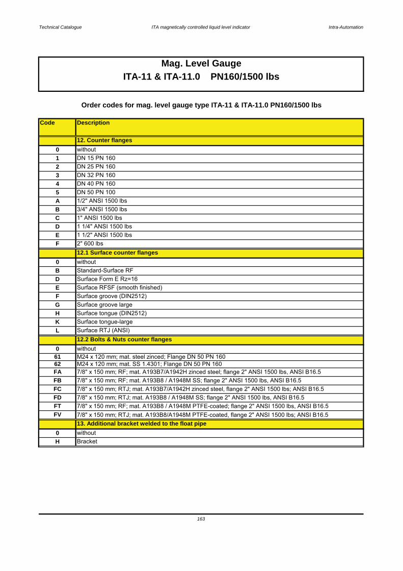
Technical Catalogue ITA magnetically controlled liquid level indicator Intra-Automation
Code Description
0 without
Order codes for mag. level gauge type ITA-11 & ITA-11.0 PN160/1500 lbs
163
Mag. Level GaugeITA-11 & ITA-11.0 PN160/1500 lbs
12.2 Bolts & Nuts counter flangesL Surface RTJ (ANSI)
M24 x 120 mm; mat. steel zinced; Flange DN 50 PN 160
H Bracket
13. Additional bracket welded to the float pipe0 without
61
H Surface tongue (DIN2512)K Surface tongue-large
F Surface groove (DIN2512)G Surface groove large
D Surface Form E Rz=16E Surface RFSF (smooth finished)
0 withoutB Standard-Surface RF
F 2" 600 lbs12.1 Surface counter flanges
D 1 1/4" ANSI 1500 lbsE 1 1/2" ANSI 1500 lbs
B 3/4" ANSI 1500 lbsC 1" ANSI 1500 lbs
5 DN 50 PN 100A 1/2" ANSI 1500 lbs
3 DN 32 PN 1604 DN 40 PN 160
1 DN 15 PN 1602 DN 25 PN 160
12. Counter flanges0 without
FB 7/8" x 150 mm; RF; mat. A193B8 / A1948M SS; flange 2" ANSI 1500 lbs, ANSI B16.5FC 7/8" x 150 mm; RTJ; mat. A193B7/A1942H zinced steel, flange 2" ANSI 1500 lbs; ANSI B16.5
M24 x 120 mm; mat. SS 1.4301; Flange DN 50 PN 160FA 7/8" x 150 mm; RF; mat. A193B7/A1942H zinced steel; flange 2" ANSI 1500 lbs, ANSI B16.562
FV 7/8" x 150 mm; RTJ; mat. A193B8/A1948M PTFE-coated, flange 2" ANSI 1500 lbs; ANSI B16.5
FD 7/8" x 150 mm; RTJ; mat. A193B8 / A1948M SS; flange 2" ANSI 1500 lbs, ANSI B16.5FT 7/8" x 150 mm; RF; mat. A193B8 / A1948M PTFE-coated; flange 2" ANSI 1500 lbs, ANSI B16.5
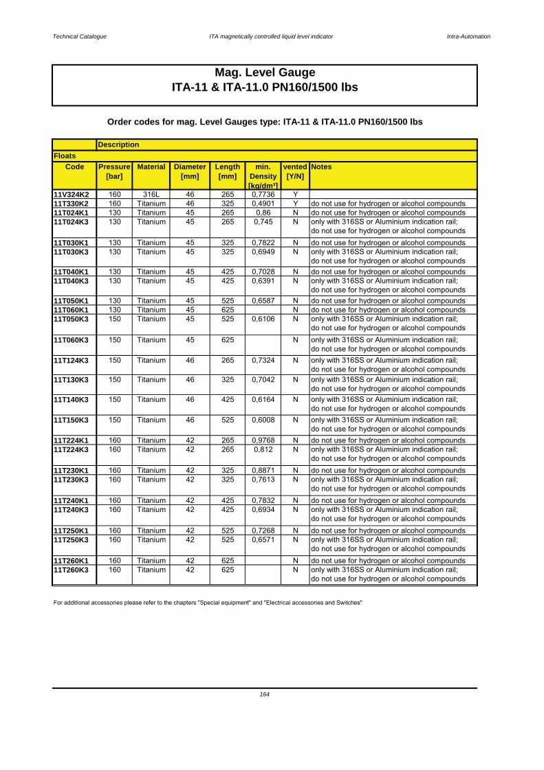
Technical Catalogue ITA magnetically controlled liquid level indicator Intra-Automation
Code Pressure[bar]
Material Diameter[mm]
Length[mm]
min. Density[kg/dm³]
vented[Y/N]
Notes
11V324K2 160 316L 46 265 0,7736 Y11T330K2 160 Titanium 46 325 0,4901 Y do not use for hydrogen or alcohol compounds11T024K1 130 Titanium 45 265 0,86 N do not use for hydrogen or alcohol compounds11T024K3 130 Titanium 45 265 0,745 N only with 316SS or Aluminium indication rail;
do not use for hydrogen or alcohol compounds11T030K1 130 Titanium 45 325 0,7822 N do not use for hydrogen or alcohol compounds11T030K3 130 Titanium 45 325 0,6949 N only with 316SS or Aluminium indication rail;
do not use for hydrogen or alcohol compounds11T040K1 130 Titanium 45 425 0,7028 N do not use for hydrogen or alcohol compounds11T040K3 130 Titanium 45 425 0,6391 N only with 316SS or Aluminium indication rail;
do not use for hydrogen or alcohol compounds11T050K1 130 Titanium 45 525 0,6587 N do not use for hydrogen or alcohol compounds11T060K1 130 Titanium 45 625 N do not use for hydrogen or alcohol compounds11T050K3 150 Titanium 45 525 0,6106 N only with 316SS or Aluminium indication rail;
do not use for hydrogen or alcohol compounds11T060K3 150 Titanium 45 625 N only with 316SS or Aluminium indication rail;
do not use for hydrogen or alcohol compounds11T124K3 150 Titanium 46 265 0,7324 N only with 316SS or Aluminium indication rail;
do not use for hydrogen or alcohol compounds11T130K3 150 Titanium 46 325 0,7042 N only with 316SS or Aluminium indication rail;
do not use for hydrogen or alcohol compounds11T140K3 150 Titanium 46 425 0,6164 N only with 316SS or Aluminium indication rail;
do not use for hydrogen or alcohol compounds11T150K3 150 Titanium 46 525 0,6008 N only with 316SS or Aluminium indication rail;
do not use for hydrogen or alcohol compounds11T224K1 160 Titanium 42 265 0,9768 N do not use for hydrogen or alcohol compounds11T224K3 160 Titanium 42 265 0,812 N only with 316SS or Aluminium indication rail;
do not use for hydrogen or alcohol compounds11T230K1 160 Titanium 42 325 0,8871 N do not use for hydrogen or alcohol compounds11T230K3 160 Titanium 42 325 0,7613 N only with 316SS or Aluminium indication rail;
do not use for hydrogen or alcohol compounds11T240K1 160 Titanium 42 425 0,7832 N do not use for hydrogen or alcohol compounds11T240K3 160 Titanium 42 425 0,6934 N only with 316SS or Aluminium indication rail;
do not use for hydrogen or alcohol compounds11T250K1 160 Titanium 42 525 0,7268 N do not use for hydrogen or alcohol compounds11T250K3 160 Titanium 42 525 0,6571 N only with 316SS or Aluminium indication rail;
do not use for hydrogen or alcohol compounds11T260K1 160 Titanium 42 625 N do not use for hydrogen or alcohol compounds11T260K3 160 Titanium 42 625 N only with 316SS or Aluminium indication rail;
do not use for hydrogen or alcohol compounds
164
Mag. Level GaugeITA-11 & ITA-11.0 PN160/1500 lbs
For additional accessories please refer to the chapters "Special equipment" and "Electrical accessories and Switches"
Order codes for mag. Level Gauges type: ITA-11 & ITA-11.0 PN160/1500 lbs
DescriptionFloats

Technical Catalogue ITA magnetically controlled liquid level indicator Intra-Automation
165
12.1 Surface counter flanges12.2 Bolts & nuts counter flanges
13. Additional bracket welded to the float pipe14. Float
10.2 Bolts and nuts rop end finish flange11. Vent plug at top end
11.1 Vent flange welded to end cap instead of vent plug11.2 Vent flange with concentric reducer (X-ray testing)
11.3 Surface vent flange welded to end cap 12. Counter flanges
ITA-11.0
9.1 Drain flange with concentric reducer (X-ray testing)9.2 Surface open drain flange
10. Float pipe top end finish10.1 Surface top end finish flange
9. Additional drain flange, open
ITA-11
7.2 Bolts & nuts float removal flange8. Drain plug
7. Float removal flange7.1 Surface float removal flange
5.1 Surface side flanges6. Side studs welded with T-pieces for 100 % X-ray-testing
4. C to C distance > 5000 mm5. Process connection [side/side]
3.20.4 Order code scheme for ITA-11 & ITA-11.0
1. Type of level gauge ITA-11 or ITA-11.02. C to C distance in mm [or inches]
3. Design
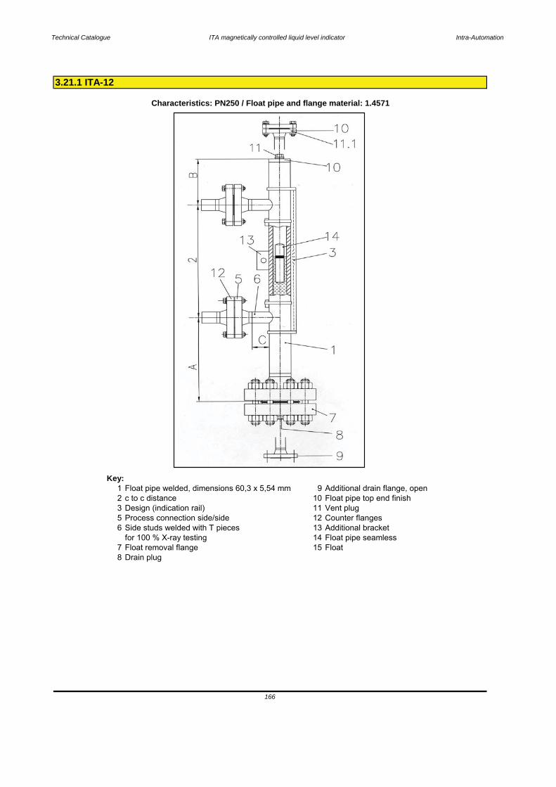
Technical Catalogue ITA magnetically controlled liquid level indicator Intra-Automation
Key:1 Float pipe welded, dimensions 60,3 x 5,54 mm 9 Additional drain flange, open2 c to c distance 10 Float pipe top end finish3 Design (indication rail) 11 Vent plug5 Process connection side/side 12 Counter flanges6 Side studs welded with T pieces 13 Additional bracket
for 100 % X-ray testing 14 Float pipe seamless7 Float removal flange 15 Float8 Drain plug
3.21.1 ITA-12
Characteristics: PN250 / Float pipe and flange material: 1.4571
166
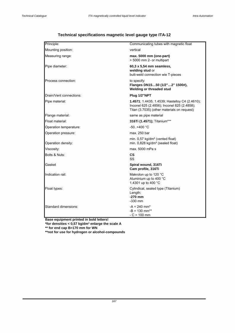
Technical Catalogue ITA magnetically controlled liquid level indicator Intra-Automation
Base equipment printed in bold letters!*for densities < 0,57 kg/dm³ enlarge the scale A** for end cap B=170 mm for WN**not for use for hydrogen or alcohol-compounds
167
Standard dimensions: -A = 240 mm*-B = 130 mm**- C = 100 mm
Length: -270 mm-330 mm
1.4301 up to 400 °CFloat types: Cylindical, sealed type (Titanium)
Indication rail: Makrolon up to 120 °CAluminium up to 400 °C
SSGasket Spiral wound, 316Ti
Cam profile, 316Ti
Bolts & Nuts: CSViscosity: max. 5000 mPa s
Operation density:min. 0,57 kg/dm³ (vented float)min. 0,828 kg/dm³ (sealed float)
Operation temperature: -50..+400 °C
Operation pressure: max. 250 bar
Float material: 316Ti (1.4571); Titanium***
Titan (3.7035) (other materials on request)Flange material: same as pipe material
Pipe material: 1.4571; 1.4435; 1.4539; Hastelloy C4 (2.4610); Inconel 625 (2.4856); Inconel 825 (2.4858);
Welding or threaded stud
Drain/Vent connections: Plug 1/2"NPT
60,3 x 5,54 mm seamless,
Process connection: to specify:Flanges DN15…50 (1/2"…2" 1500#),
Measuring range: max. 5000 mm (one-part)> 5000 mm 2- or multipart
welding stud or butt-weld connection wie T-pieces
Pipe diameter:
Mounting position: vertical
Technical specifications magnetic level gauge type ITA-12
Principle: Communicating tubes with magnetic float
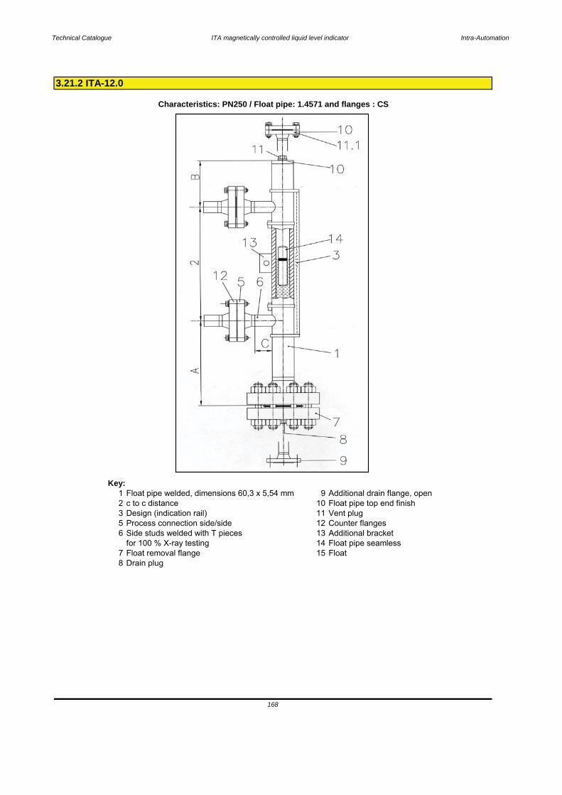
Technical Catalogue ITA magnetically controlled liquid level indicator Intra-Automation
Key:1 Float pipe welded, dimensions 60,3 x 5,54 mm 9 Additional drain flange, open2 c to c distance 10 Float pipe top end finish3 Design (indication rail) 11 Vent plug5 Process connection side/side 12 Counter flanges6 Side studs welded with T pieces 13 Additional bracket
for 100 % X-ray testing 14 Float pipe seamless7 Float removal flange 15 Float8 Drain plug
3.21.2 ITA-12.0
Characteristics: PN250 / Float pipe: 1.4571 and flanges : CS
168
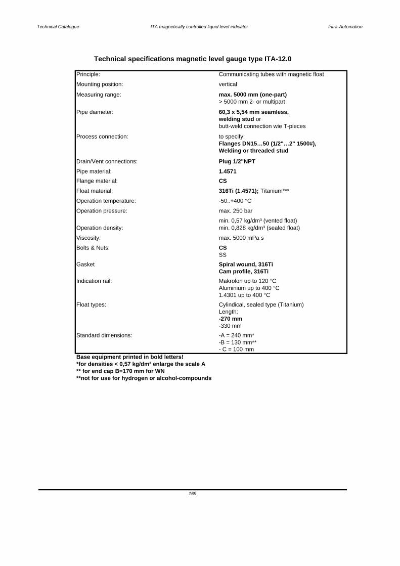
Technical Catalogue ITA magnetically controlled liquid level indicator Intra-Automation
Base equipment printed in bold letters!*for densities < 0,57 kg/dm³ enlarge the scale A** for end cap B=170 mm for WN**not for use for hydrogen or alcohol-compounds
Technical specifications magnetic level gauge type ITA-12.0
Principle: Communicating tubes with magnetic float
Mounting position: vertical
Measuring range: max. 5000 mm (one-part)> 5000 mm 2- or multipart
Pipe diameter: 60,3 x 5,54 mm seamless,welding stud or butt-weld connection wie T-pieces
Process connection: to specify:Flanges DN15…50 (1/2"…2" 1500#),Welding or threaded stud
Drain/Vent connections: Plug 1/2"NPTPipe material: 1.4571Flange material: CSFloat material: 316Ti (1.4571); Titanium***
Operation temperature: -50..+400 °C
Operation pressure: max. 250 bar
Operation density:min. 0,57 kg/dm³ (vented float)min. 0,828 kg/dm³ (sealed float)
Bolts & Nuts: CSViscosity: max. 5000 mPa s
SS
Gasket Spiral wound, 316TiCam profile, 316Ti
Indication rail: Makrolon up to 120 °CAluminium up to 400 °C1.4301 up to 400 °C
Float types: Cylindical, sealed type (Titanium)Length:
-B = 130 mm**
-270 mm-330 mm
169
Standard dimensions: -A = 240 mm*
- C = 100 mm

3.21.3 Pressure-Temperature Table ITA-12 (Float pipe)
170
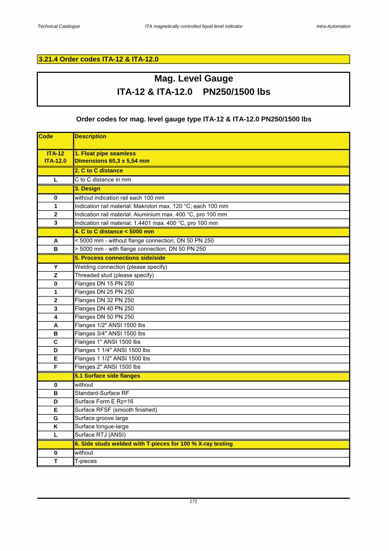
Technical Catalogue ITA magnetically controlled liquid level indicator Intra-Automation
Code Description
Mag. Level GaugeITA-12 & ITA-12.0 PN250/1500 lbs
B Standard-Surface RFD Surface Form E Rz=16
3.21.4 Order codes ITA-12 & ITA-12.0
T
6. Side studs welded with T-pieces for 100 % X-ray testing0 without
171
T-pieces
E Surface RFSF (smooth finished)G Surface groove largeK Surface tongue-largeL Surface RTJ (ANSI)
5.1 Surface side flanges0 without
E Flanges 1 1/2" ANSI 1500 lbsF Flanges 2" ANSI 1500 lbs
C Flanges 1" ANSI 1500 lbsD Flanges 1 1/4" ANSI 1500 lbs
A Flanges 1/2" ANSI 1500 lbs B Flanges 3/4" ANSI 1500 lbs
3 Flanges DN 40 PN 2504 Flanges DN 50 PN 250
1 Flanges DN 25 PN 2502 Flanges DN 32 PN 250
Z Threaded stud (please specify)0 Flanges DN 15 PN 250
5. Process connections side/sideY Welding connection (please specify)
A < 5000 mm - without flange connection; DN 50 PN 250B > 5000 mm - with flange connection; DN 50 PN 250
3 Indication rail material: 1.4401 max. 400 °C, pro 100 mm4. C to C distance < 5000 mm
1 Indication rail material: Makrolon max. 120 °C; each 100 mm2 Indication rail material: Aluminium max. 400 °C, pro 100 mm
3. Design0 without indication rail each 100 mm
L C to C distance in mm
Order codes for mag. level gauge type ITA-12 & ITA-12.0 PN250/1500 lbs
ITA-12ITA-12.0
1. Float pipe seamlessDimensions 60,3 x 5,54 mm2. C to C distance
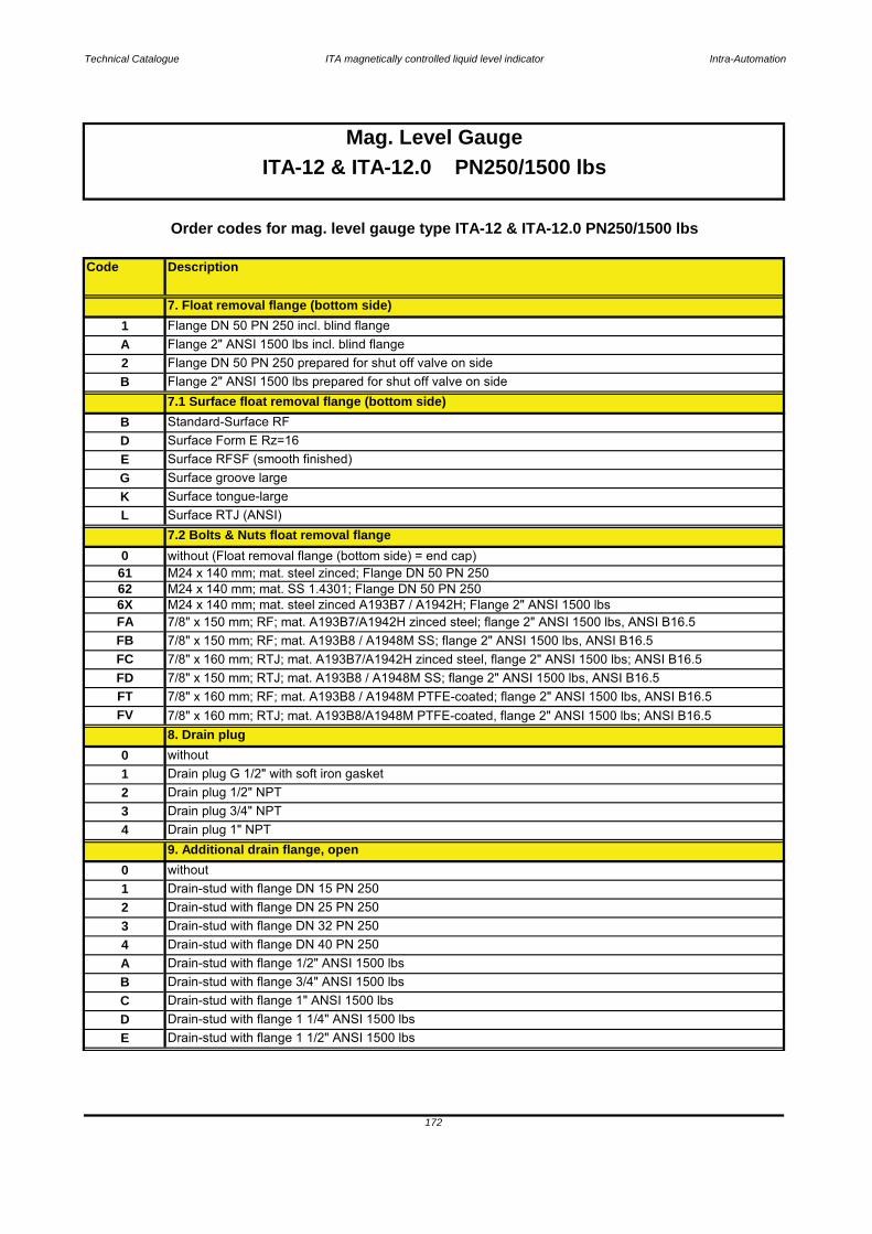
Technical Catalogue ITA magnetically controlled liquid level indicator Intra-Automation
Code Description
172
Mag. Level GaugeITA-12 & ITA-12.0 PN250/1500 lbs
D Drain-stud with flange 1 1/4" ANSI 1500 lbsE Drain-stud with flange 1 1/2" ANSI 1500 lbs
B Drain-stud with flange 3/4" ANSI 1500 lbsC Drain-stud with flange 1" ANSI 1500 lbs
4 Drain-stud with flange DN 40 PN 250A Drain-stud with flange 1/2" ANSI 1500 lbs
2 Drain-stud with flange DN 25 PN 2503 Drain-stud with flange DN 32 PN 250
0 without1 Drain-stud with flange DN 15 PN 250
9. Additional drain flange, open
2 Drain plug 1/2" NPT3 Drain plug 3/4" NPT
8. Drain plug0 without
4 Drain plug 1" NPT
7.2 Bolts & Nuts float removal flange
Order codes for mag. level gauge type ITA-12 & ITA-12.0 PN250/1500 lbs
Surface tongue-largeL Surface RTJ (ANSI) K
D Surface Form E Rz=16
G Surface groove largeE Surface RFSF (smooth finished)
7.1 Surface float removal flange (bottom side)B Standard-Surface RF
1 Flange DN 50 PN 250 incl. blind flange
2 Flange DN 50 PN 250 prepared for shut off valve on sideB Flange 2" ANSI 1500 lbs prepared for shut off valve on side
7. Float removal flange (bottom side)
A Flange 2" ANSI 1500 lbs incl. blind flange
6X M24 x 140 mm; mat. steel zinced A193B7 / A1942H; Flange 2" ANSI 1500 lbs
0 without (Float removal flange (bottom side) = end cap)61 M24 x 140 mm; mat. steel zinced; Flange DN 50 PN 250
FC 7/8" x 160 mm; RTJ; mat. A193B7/A1942H zinced steel, flange 2" ANSI 1500 lbs; ANSI B16.5FD 7/8" x 150 mm; RTJ; mat. A193B8 / A1948M SS; flange 2" ANSI 1500 lbs, ANSI B16.5
62 M24 x 140 mm; mat. SS 1.4301; Flange DN 50 PN 250
FB 7/8" x 150 mm; RF; mat. A193B8 / A1948M SS; flange 2" ANSI 1500 lbs, ANSI B16.5FA 7/8" x 150 mm; RF; mat. A193B7/A1942H zinced steel; flange 2" ANSI 1500 lbs, ANSI B16.5
FT 7/8" x 160 mm; RF; mat. A193B8 / A1948M PTFE-coated; flange 2" ANSI 1500 lbs, ANSI B16.5FV 7/8" x 160 mm; RTJ; mat. A193B8/A1948M PTFE-coated, flange 2" ANSI 1500 lbs; ANSI B16.5
1 Drain plug G 1/2" with soft iron gasket
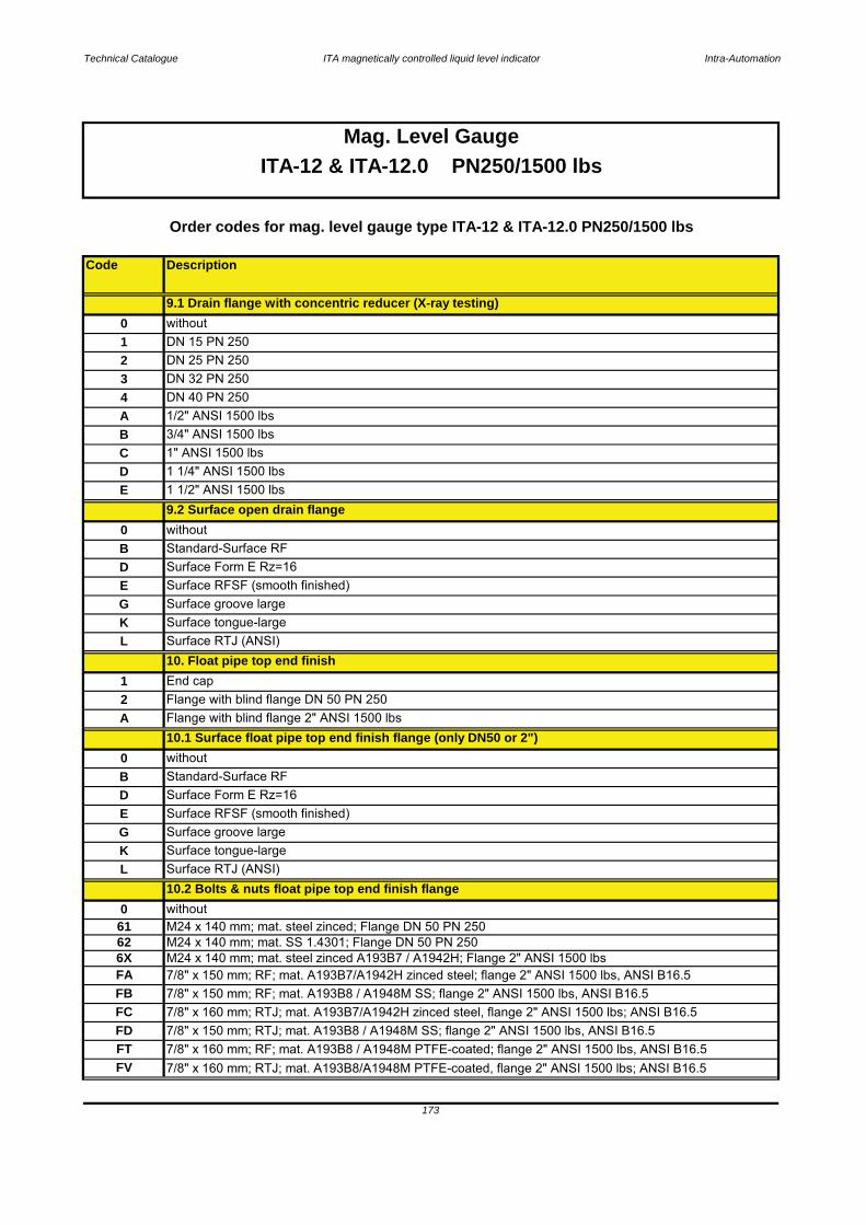
Technical Catalogue ITA magnetically controlled liquid level indicator Intra-Automation
Code Description
Mag. Level Gauge
173
Order codes for mag. level gauge type ITA-12 & ITA-12.0 PN250/1500 lbs
K Surface tongue-large
0 without
62 M24 x 140 mm; mat. SS 1.4301; Flange DN 50 PN 25061 M24 x 140 mm; mat. steel zinced; Flange DN 50 PN 250
E Surface RFSF (smooth finished)G
10.2 Bolts & nuts float pipe top end finish flangeL Surface RTJ (ANSI)
Surface groove large
A Flange with blind flange 2" ANSI 1500 lbs10.1 Surface float pipe top end finish flange (only DN50 or 2")
D Surface Form E Rz=16
0 withoutB Standard-Surface RF
L Surface RTJ (ANSI) 10. Float pipe top end finish
1 End cap 2 Flange with blind flange DN 50 PN 250
D Surface Form E Rz=16E Surface RFSF (smooth finished)G Surface groove largeK Surface tongue-large
0 withoutB Standard-Surface RF
E 1 1/2" ANSI 1500 lbs9.2 Surface open drain flange
C 1" ANSI 1500 lbsD 1 1/4" ANSI 1500 lbs
A 1/2" ANSI 1500 lbs B 3/4" ANSI 1500 lbs
3 DN 32 PN 2504 DN 40 PN 250
1 DN 15 PN 2502 DN 25 PN 250
9.1 Drain flange with concentric reducer (X-ray testing)0 without
ITA-12 & ITA-12.0 PN250/1500 lbs
M24 x 140 mm; mat. steel zinced A193B7 / A1942H; Flange 2" ANSI 1500 lbsFA 7/8" x 150 mm; RF; mat. A193B7/A1942H zinced steel; flange 2" ANSI 1500 lbs, ANSI B16.56X
FD 7/8" x 150 mm; RTJ; mat. A193B8 / A1948M SS; flange 2" ANSI 1500 lbs, ANSI B16.5FT 7/8" x 160 mm; RF; mat. A193B8 / A1948M PTFE-coated; flange 2" ANSI 1500 lbs, ANSI B16.5
FB 7/8" x 150 mm; RF; mat. A193B8 / A1948M SS; flange 2" ANSI 1500 lbs, ANSI B16.5FC 7/8" x 160 mm; RTJ; mat. A193B7/A1942H zinced steel, flange 2" ANSI 1500 lbs; ANSI B16.5
FV 7/8" x 160 mm; RTJ; mat. A193B8/A1948M PTFE-coated, flange 2" ANSI 1500 lbs; ANSI B16.5
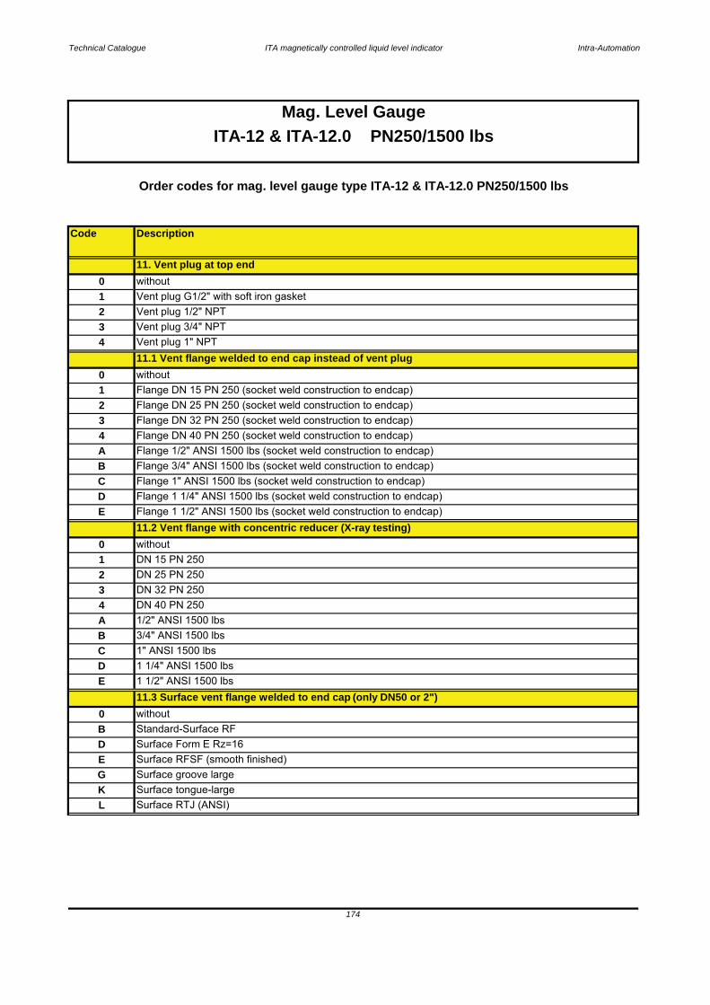
Technical Catalogue ITA magnetically controlled liquid level indicator Intra-Automation
Code Description
174
Mag. Level GaugeITA-12 & ITA-12.0 PN250/1500 lbs
Order codes for mag. level gauge type ITA-12 & ITA-12.0 PN250/1500 lbs
K Surface tongue-largeL Surface RTJ (ANSI)
E Surface RFSF (smooth finished)G Surface groove large
B Standard-Surface RFD Surface Form E Rz=16
11.3 Surface vent flange welded to end cap (only DN50 or 2")0 without
D 1 1/4" ANSI 1500 lbsE 1 1/2" ANSI 1500 lbs
B 3/4" ANSI 1500 lbsC 1" ANSI 1500 lbs
4 DN 40 PN 250A 1/2" ANSI 1500 lbs
2 DN 25 PN 2503 DN 32 PN 250
0 without1 DN 15 PN 250
E Flange 1 1/2" ANSI 1500 lbs (socket weld construction to endcap)11.2 Vent flange with concentric reducer (X-ray testing)
C Flange 1" ANSI 1500 lbs (socket weld construction to endcap)D Flange 1 1/4" ANSI 1500 lbs (socket weld construction to endcap)
A Flange 1/2" ANSI 1500 lbs (socket weld construction to endcap)B Flange 3/4" ANSI 1500 lbs (socket weld construction to endcap)
3 Flange DN 32 PN 250 (socket weld construction to endcap)4 Flange DN 40 PN 250 (socket weld construction to endcap)
1 Flange DN 15 PN 250 (socket weld construction to endcap)2 Flange DN 25 PN 250 (socket weld construction to endcap)
0 without
11.1 Vent flange welded to end cap instead of vent plug0 without
3 Vent plug 3/4" NPT4 Vent plug 1" NPT
1 Vent plug G1/2" with soft iron gasket2 Vent plug 1/2" NPT
11. Vent plug at top end
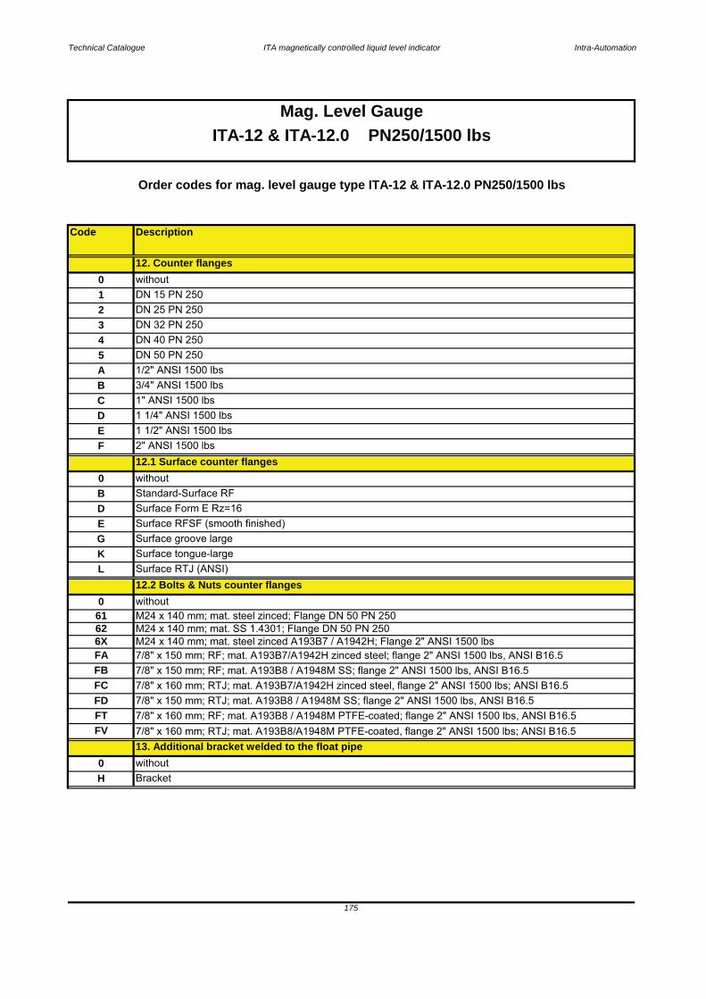
Technical Catalogue ITA magnetically controlled liquid level indicator Intra-Automation
Code Description
Surface tongue-large
175
Mag. Level GaugeITA-12 & ITA-12.0 PN250/1500 lbs
Order codes for mag. level gauge type ITA-12 & ITA-12.0 PN250/1500 lbs
0 withoutB
1 1/4" ANSI 1500 lbs
7/8" x 150 mm; RF; mat. A193B8 / A1948M SS; flange 2" ANSI 1500 lbs, ANSI B16.5
M24 x 140 mm; mat. SS 1.4301; Flange DN 50 PN 250
Surface Form E Rz=16E Surface RFSF (smooth finished)
Surface groove large
Surface RTJ (ANSI) 12.2 Bolts & Nuts counter flanges
B
L
without
without0
62
FAM24 x 140 mm; mat. steel zinced A193B7 / A1942H; Flange 2" ANSI 1500 lbs
C
7/8" x 150 mm; RF; mat. A193B7/A1942H zinced steel; flange 2" ANSI 1500 lbs, ANSI B16.5
G
H
K
6X
D
0
FB
7/8" x 150 mm; RTJ; mat. A193B8 / A1948M SS; flange 2" ANSI 1500 lbs, ANSI B16.57/8" x 160 mm; RF; mat. A193B8 / A1948M PTFE-coated; flange 2" ANSI 1500 lbs, ANSI B16.5
FV 7/8" x 160 mm; RTJ; mat. A193B8/A1948M PTFE-coated, flange 2" ANSI 1500 lbs; ANSI B16.5FT
FC
Bracket
13. Additional bracket welded to the float pipe
7/8" x 160 mm; RTJ; mat. A193B7/A1942H zinced steel, flange 2" ANSI 1500 lbs; ANSI B16.5FD
1 1/2" ANSI 1500 lbs
0
DN 32 PN 250
withoutDN 15 PN 250
Standard-Surface RF
12.1 Surface counter flangesF 2" ANSI 1500 lbs
2
E
A 1/2" ANSI 1500 lbs 5 DN 50 PN 250
1DN 25 PN 250
34
3/4" ANSI 1500 lbs
D
12. Counter flanges
1" ANSI 1500 lbs
DN 40 PN 250
61 M24 x 140 mm; mat. steel zinced; Flange DN 50 PN 250
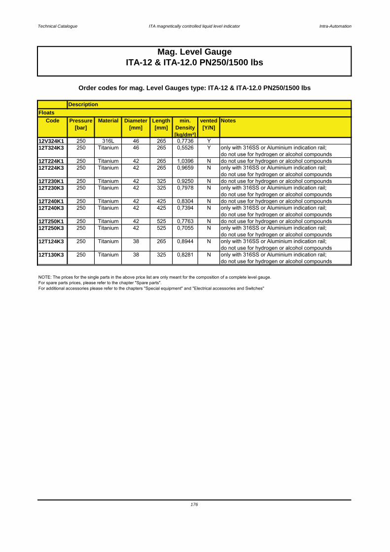
Technical Catalogue ITA magnetically controlled liquid level indicator Intra-Automation
Code Pressure[bar]
Material Diameter[mm]
Length[mm]
min. Density[kg/dm³]
vented[Y/N]
Notes
12V324K1 250 316L 46 265 0,7736 Y12T324K3 250 Titanium 46 265 0,5526 Y only with 316SS or Aluminium indication rail;
do not use for hydrogen or alcohol compounds12T224K1 250 Titanium 42 265 1,0396 N do not use for hydrogen or alcohol compounds12T224K3 250 Titanium 42 265 0,9659 N only with 316SS or Aluminium indication rail;
do not use for hydrogen or alcohol compounds12T230K1 250 Titanium 42 325 0,9250 N do not use for hydrogen or alcohol compounds12T230K3 250 Titanium 42 325 0,7978 N only with 316SS or Aluminium indication rail;
do not use for hydrogen or alcohol compounds12T240K1 250 Titanium 42 425 0,8304 N do not use for hydrogen or alcohol compounds12T240K3 250 Titanium 42 425 0,7394 N only with 316SS or Aluminium indication rail;
do not use for hydrogen or alcohol compounds12T250K1 250 Titanium 42 525 0,7763 N do not use for hydrogen or alcohol compounds12T250K3 250 Titanium 42 525 0,7055 N only with 316SS or Aluminium indication rail;
do not use for hydrogen or alcohol compounds12T124K3 250 Titanium 38 265 0,8944 N only with 316SS or Aluminium indication rail;
do not use for hydrogen or alcohol compounds12T130K3 250 Titanium 38 325 0,8281 N only with 316SS or Aluminium indication rail;
do not use for hydrogen or alcohol compounds
176
Mag. Level GaugeITA-12 & ITA-12.0 PN250/1500 lbs
NOTE: The prices for the single parts in the above price list are only meant for the composition of a complete level gauge.For spare parts prices, please refer to the chapter "Spare parts".For additional accessories please refer to the chapters "Special equipment" and "Electrical accessories and Switches"
Order codes for mag. Level Gauges type: ITA-12 & ITA-12.0 PN250/1500 lbs
DescriptionFloats

Technical Catalogue ITA magnetically controlled liquid level indicator Intra-Automation
177
12.1 Surface counter flanges12.2 Bolts & nuts counter flanges
13. Additional bracket welded to the float pipe14. Float
10.2 Bolts and nuts rop end finish flange11. Vent plug at top end
11.1 Vent flange welded to end cap instead of vent plug11.2 Vent flange with concentric reducer (X-ray testing)
11.3 Surface vent flange welded to end cap 12. Counter flanges
ITA-12.0
9.1 Drain flange with concentric reducer (X-ray testing)9.2 Surface open drain flange
10. Float pipe top end finish10.1 Surface top end finish flange
9. Additional drain flange, open
ITA-12
7.2 Bolts & nuts float removal flange8. Drain plug
7. Float removal flange7.1 Surface float removal flange
5.1 Surface side flanges6. Side studs welded with T-pieces for 100 % X-ray-testing
4. C to C distance > 5000 mm5. Process connection [side/side]
3.21.4 Order code scheme for ITA-12 & ITA-12.0
1. Type of level gauge ITA-12 or ITA-12.02. C to C distance in mm [or inches]
3. Design
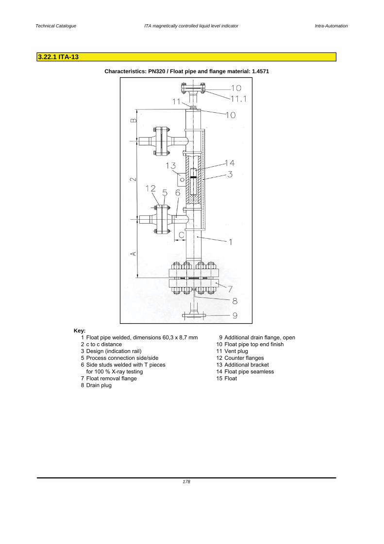
Technical Catalogue ITA magnetically controlled liquid level indicator Intra-Automation
Key:1 Float pipe welded, dimensions 60,3 x 8,7 mm 9 Additional drain flange, open2 c to c distance 10 Float pipe top end finish3 Design (indication rail) 11 Vent plug5 Process connection side/side 12 Counter flanges6 Side studs welded with T pieces 13 Additional bracket
for 100 % X-ray testing 14 Float pipe seamless7 Float removal flange 15 Float8 Drain plug
3.22.1 ITA-13
Characteristics: PN320 / Float pipe and flange material: 1.4571
178
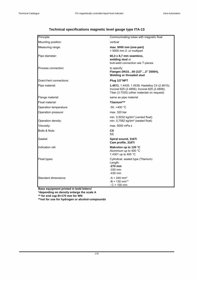
Technical Catalogue ITA magnetically controlled liquid level indicator Intra-Automation
Base equipment printed in bold letters!*depending on density enlarge the scale A** for end cap B=170 mm for WN**not for use for hydrogen or alcohol-compounds
-430 mm
- C = 100 mm
179
Standard dimensions: -A = 240 mm*-B = 130 mm**
Length: -270 mm-330 mm
1.4301 up to 400 °CFloat types: Cylindical, sealed type (Titanium)
Indication rail: Makrolon up to 120 °CAluminium up to 400 °C
SSGasket Spiral wound, 316Ti
Cam profile, 316Ti
Operation density:min. 0,5032 kg/dm³ (vented float)min. 0,7582 kg/dm³ (sealed float)
Bolts & Nuts: CSViscosity: max. 5000 mPa s
Operation pressure: max. 320 bar
Float material: Titanium***Operation temperature: -50..+400 °C
Flange material: same as pipe material
Pipe material: 1.4571; 1.4435; 1.4539; Hastelloy C4 (2.4610); Inconel 625 (2.4856); Inconel 825 (2.4858);Titan (3.7035) (other materials on request)
Drain/Vent connections: Plug 1/2"NPT
Process connection: to specify:Flanges DN15…50 (1/2"…2" 2500#),Welding or threaded stud
Pipe diameter: 60,3 x 8,7 mm seamless,welding stud or butt-weld connection wie T-pieces
Measuring range: max. 5000 mm (one-part)> 5000 mm 2- or multipart
Mounting position: vertical
Technical specifications magnetic level gauge type ITA-13
Principle: Communicating tubes with magnetic float

Technical Catalogue ITA magnetically controlled liquid level indicator Intra-Automation
Key:1 Float pipe welded, dimensions 60,3 x 8,7 mm 9 Additional drain flange, open2 c to c distance 10 Float pipe top end finish3 Design (indication rail) 11 Vent plug5 Process connection side/side 12 Counter flanges6 Side studs welded with T pieces 13 Additional bracket
for 100 % X-ray testing 14 Float pipe seamless7 Float removal flange 15 Float8 Drain plug
3.22.2 ITA-13.0
Characteristics: PN320 / Float pipe: 1.4571 and flanges : CS
180
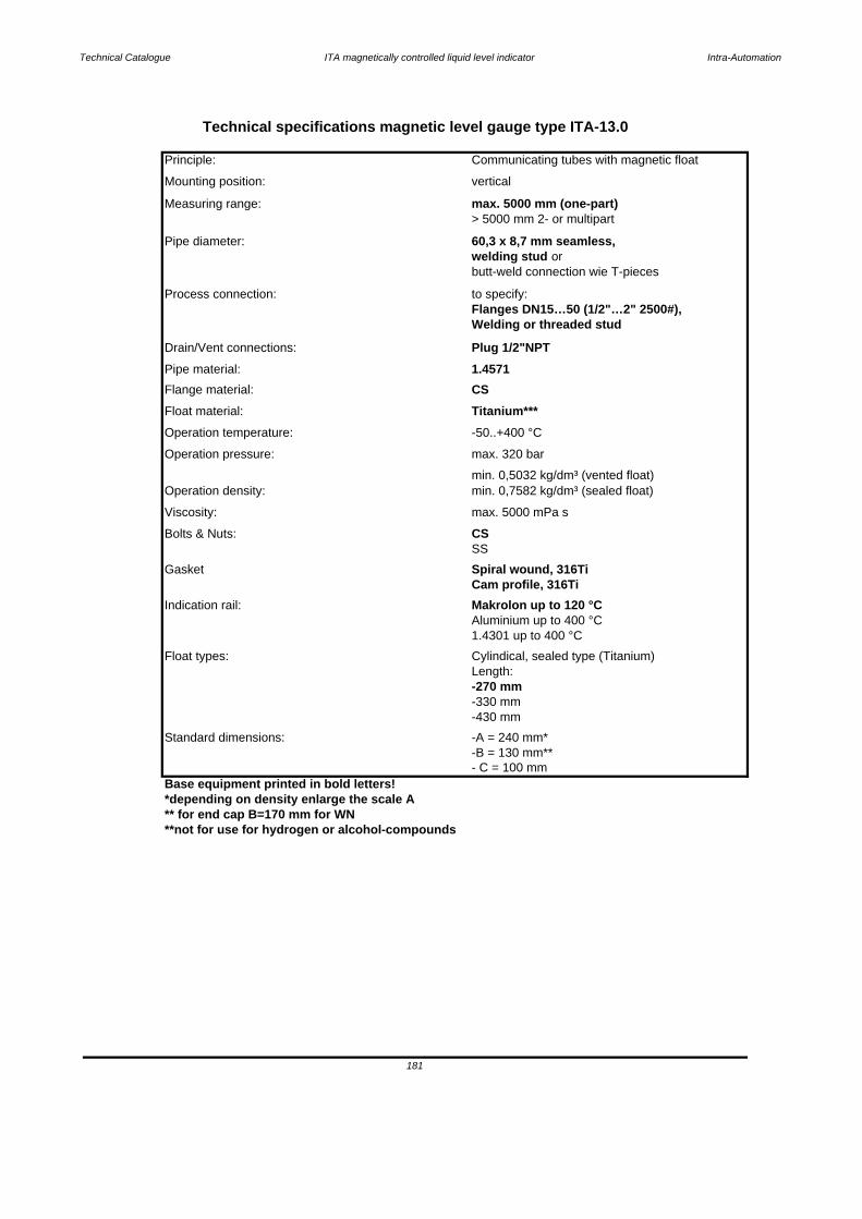
Technical Catalogue ITA magnetically controlled liquid level indicator Intra-Automation
Base equipment printed in bold letters!*depending on density enlarge the scale A** for end cap B=170 mm for WN**not for use for hydrogen or alcohol-compounds
Technical specifications magnetic level gauge type ITA-13.0
Principle: Communicating tubes with magnetic float
Mounting position: vertical
Measuring range: max. 5000 mm (one-part)> 5000 mm 2- or multipart
Pipe diameter: 60,3 x 8,7 mm seamless,welding stud or butt-weld connection wie T-pieces
Process connection: to specify:Flanges DN15…50 (1/2"…2" 2500#),Welding or threaded stud
Drain/Vent connections: Plug 1/2"NPTPipe material: 1.4571Flange material: CSFloat material: Titanium***Operation temperature: -50..+400 °C
Operation pressure: max. 320 bar
Operation density:min. 0,5032 kg/dm³ (vented float)min. 0,7582 kg/dm³ (sealed float)
Bolts & Nuts: CSViscosity: max. 5000 mPa s
SS
Gasket Spiral wound, 316TiCam profile, 316Ti
Indication rail: Makrolon up to 120 °CAluminium up to 400 °C1.4301 up to 400 °C
Float types: Cylindical, sealed type (Titanium)Length: -270 mm-330 mm
181
- C = 100 mm
Standard dimensions: -A = 240 mm*-B = 130 mm**
-430 mm

3.22.3 Pressure-Temperature Table ITA-13 (Float pipe)
182
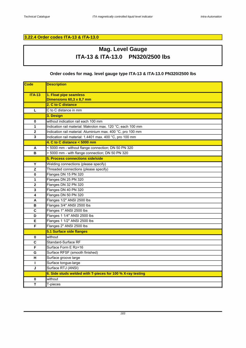
Technical Catalogue ITA magnetically controlled liquid level indicator Intra-Automation
Code Description
3.22.4 Order codes ITA-13 & ITA-13.0
183
0 withoutT T-pieces
J Surface RTJ (ANSI) 6. Side studs welded with T-pieces for 100 % X-ray testing
H Surface groove largeI Surface tongue-large
F Surface Form E Rz=16G Surface RFSF (smooth finished)
0 withoutC Standard-Surface RF
F Flanges 2" ANSI 2500 lbs5.1 Surface side flanges
D Flanges 1 1/4" ANSI 2500 lbsE Flanges 1 1/2" ANSI 2500 lbs
B Flanges 3/4" ANSI 2500 lbsC Flanges 1" ANSI 2500 lbs
4 Flanges DN 50 PN 320A Flanges 1/2" ANSI 2500 lbs
2 Flanges DN 32 PN 3203 Flanges DN 40 PN 320
1 Flanges DN 25 PN 320
Y Welding connections (please specify)Z Threaded connections (please specify)
A < 5000 mm - without flange connection; DN 50 PN 320
3 Indication rail material: 1.4401 max. 400 °C, pro 100 mm
0 Flanges DN 15 PN 320
ITA-13 1. Float pipe seamlessDimensions 60,3 x 8,7 mm
3. Design
4. C to C distance < 5000 mm
Indication rail material: Makrolon max. 120 °C; each 100 mm
L C to C distance in mm
2 Indication rail material: Aluminium max. 400 °C, pro 100 mm
0 without indication rail each 100 mm
B > 5000 mm - with flange connection; DN 50 PN 3205. Process connections side/side
Mag. Level GaugeITA-13 & ITA-13.0 PN320/2500 lbs
Order codes for mag. level gauge type ITA-13 & ITA-13.0 PN320/2500 lbs
2. C to C distance
1
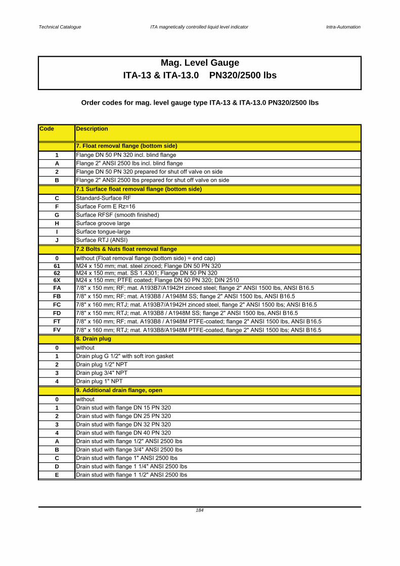
Technical Catalogue ITA magnetically controlled liquid level indicator Intra-Automation
Code Description
184
Mag. Level GaugeITA-13 & ITA-13.0 PN320/2500 lbs
Order codes for mag. level gauge type ITA-13 & ITA-13.0 PN320/2500 lbs
D Drain stud with flange 1 1/4" ANSI 2500 lbsE Drain stud with flange 1 1/2" ANSI 2500 lbs
B Drain stud with flange 3/4" ANSI 2500 lbsC Drain stud with flange 1" ANSI 2500 lbs
4 Drain stud with flange DN 40 PN 320A Drain stud with flange 1/2" ANSI 2500 lbs
2 Drain stud with flange DN 25 PN 3203 Drain stud with flange DN 32 PN 320
0 without1 Drain stud with flange DN 15 PN 320
4 Drain plug 1" NPT9. Additional drain flange, open
2 Drain plug 1/2" NPT3 Drain plug 3/4" NPT
0 without1 Drain plug G 1/2" with soft iron gasket
8. Drain plug
I Surface tongue-largeJ Surface RTJ (ANSI)
7.2 Bolts & Nuts float removal flange061
Surface Form E Rz=16
B Flange 2" ANSI 2500 lbs prepared for shut off valve on side
C Standard-Surface RF
H
7.1 Surface float removal flange (bottom side)
62 M24 x 150 mm; mat. SS 1.4301; Flange DN 50 PN 320
Surface groove large
without (Float removal flange (bottom side) = end cap)M24 x 150 mm; mat. steel zinced; Flange DN 50 PN 320
A Flange 2" ANSI 2500 lbs incl. blind flange2 Flange DN 50 PN 320 prepared for shut off valve on side
G Surface RFSF (smooth finished)F
7. Float removal flange (bottom side)1 Flange DN 50 PN 320 incl. blind flange
FA 7/8" x 150 mm; RF; mat. A193B7/A1942H zinced steel; flange 2" ANSI 1500 lbs, ANSI B16.5FB 7/8" x 150 mm; RF; mat. A193B8 / A1948M SS; flange 2" ANSI 1500 lbs, ANSI B16.5
6X M24 x 150 mm; PTFE coated; Flange DN 50 PN 320; DIN 2510
FT 7/8" x 160 mm; RF; mat. A193B8 / A1948M PTFE-coated; flange 2" ANSI 1500 lbs, ANSI B16.5FV 7/8" x 160 mm; RTJ; mat. A193B8/A1948M PTFE-coated, flange 2" ANSI 1500 lbs; ANSI B16.5
FC 7/8" x 160 mm; RTJ; mat. A193B7/A1942H zinced steel, flange 2" ANSI 1500 lbs; ANSI B16.5FD 7/8" x 150 mm; RTJ; mat. A193B8 / A1948M SS; flange 2" ANSI 1500 lbs, ANSI B16.5
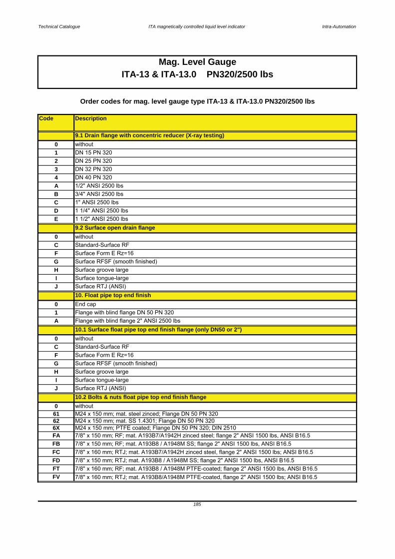
Technical Catalogue ITA magnetically controlled liquid level indicator Intra-Automation
Code Description
185
Mag. Level GaugeITA-13 & ITA-13.0 PN320/2500 lbs
0 without61 M24 x 150 mm; mat. steel zinced; Flange DN 50 PN 320
J Surface RTJ (ANSI) 10.2 Bolts & nuts float pipe top end finish flange
I Surface tongue-large
F Surface Form E Rz=16G Surface RFSF (smooth finished)
C Standard-Surface RF0 without
H Surface groove large
0 End cap 1 Flange with blind flange DN 50 PN 320A
10.1 Surface float pipe top end finish flange (only DN50 or 2")
J Surface RTJ (ANSI) 10. Float pipe top end finish
Flange with blind flange 2" ANSI 2500 lbs
Order codes for mag. level gauge type ITA-13 & ITA-13.0 PN320/2500 lbs
0 without
H Surface groove largeG Surface RFSF (smooth finished)
I Surface tongue-large
E 1 1/2" ANSI 2500 lbs
C Standard-Surface RFF Surface Form E Rz=16
9.2 Surface open drain flange
A 1/2" ANSI 2500 lbs B 3/4" ANSI 2500 lbsC 1" ANSI 2500 lbsD 1 1/4" ANSI 2500 lbs
3 DN 32 PN 3204 DN 40 PN 320
1 DN 15 PN 3202 DN 25 PN 320
9.1 Drain flange with concentric reducer (X-ray testing)0 without
M24 x 150 mm; PTFE coated; Flange DN 50 PN 320; DIN 251062
FA 7/8" x 150 mm; RF; mat. A193B7/A1942H zinced steel; flange 2" ANSI 1500 lbs, ANSI B16.5
M24 x 150 mm; mat. SS 1.4301; Flange DN 50 PN 3206X
FD 7/8" x 150 mm; RTJ; mat. A193B8 / A1948M SS; flange 2" ANSI 1500 lbs, ANSI B16.5FT 7/8" x 160 mm; RF; mat. A193B8 / A1948M PTFE-coated; flange 2" ANSI 1500 lbs, ANSI B16.5
FB 7/8" x 150 mm; RF; mat. A193B8 / A1948M SS; flange 2" ANSI 1500 lbs, ANSI B16.5FC 7/8" x 160 mm; RTJ; mat. A193B7/A1942H zinced steel, flange 2" ANSI 1500 lbs; ANSI B16.5
FV 7/8" x 160 mm; RTJ; mat. A193B8/A1948M PTFE-coated, flange 2" ANSI 1500 lbs; ANSI B16.5
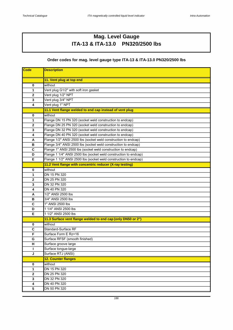
Technical Catalogue ITA magnetically controlled liquid level indicator Intra-Automation
Code Description
Mag. Level GaugeITA-13 & ITA-13.0 PN320/2500 lbs
Order codes for mag. level gauge type ITA-13 & ITA-13.0 PN320/2500 lbs
0 without1
J
186
DN 32 PN 3204
DN 50 PN 320
Surface Form E Rz=16G
Surface RTJ (ANSI)
Surface RFSF (smooth finished)
C Standard-Surface RF
2 DN 25 PN 3203
DN 40 PN 3205
DN 15 PN 320
H Surface groove large
11.3 Surface vent flange welded to end cap (only DN50 or 2")
12. Counter flanges
0 without
F
B 3/4" ANSI 2500 lbsC 1" ANSI 2500 lbs
I Surface tongue-large
1 1/4" ANSI 2500 lbsE 1 1/2" ANSI 2500 lbsD
2 DN 25 PN 3203 DN 32 PN 320
A 1/2" ANSI 2500 lbs 4 DN 40 PN 320
0 without1 DN 15 PN 320
E Flange 1 1/2" ANSI 2500 lbs (socket weld construction to endcap)11.2 Vent flange with concentric reducer (X-ray testing)
C Flange 1" ANSI 2500 lbs (socket weld construction to endcap)D Flange 1 1/4" ANSI 2500 lbs (socket weld construction to endcap)
A Flange 1/2" ANSI 2500 lbs (socket weld construction to endcap)B Flange 3/4" ANSI 2500 lbs (socket weld construction to endcap)
3 Flange DN 32 PN 320 (socket weld construction to endcap)4 Flange DN 40 PN 320 (socket weld construction to endcap)
1 Flange DN 15 PN 320 (socket weld construction to endcap)2 Flange DN 25 PN 320 (socket weld construction to endcap)
0 without
11.1 Vent flange welded to end cap instead of vent plug0 without
3 Vent plug 3/4" NPT4 Vent plug 1" NPT
1 Vent plug G1/2" with soft iron gasket2 Vent plug 1/2" NPT
11. Vent plug at top end
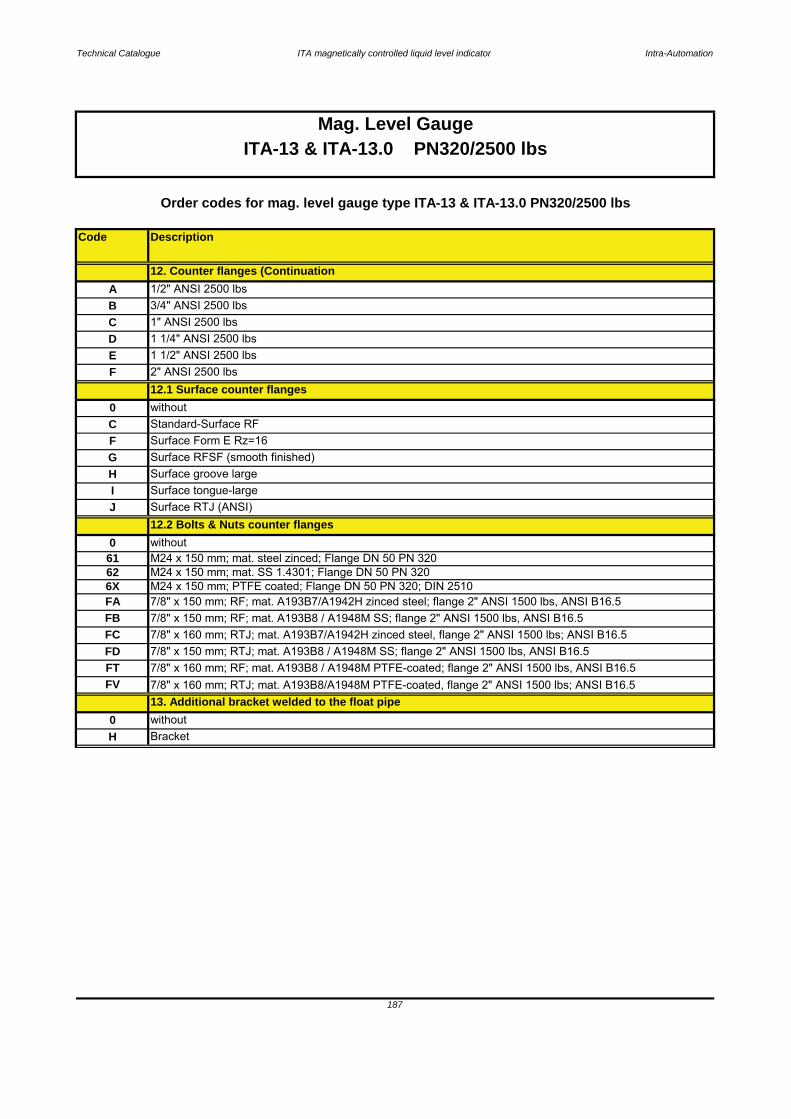
Technical Catalogue ITA magnetically controlled liquid level indicator Intra-Automation
Code Description
187
12. Counter flanges (Continuation
Mag. Level Gauge
E 1 1/2" ANSI 2500 lbs
C 1" ANSI 2500 lbsB 3/4" ANSI 2500 lbs
13. Additional bracket welded to the float pipe0 without
A 1/2" ANSI 2500 lbs
H Bracket
I Surface tongue-largeJ Surface RTJ (ANSI)
12.2 Bolts & Nuts counter flanges0 without
G Surface RFSF (smooth finished)H Surface groove large
C Standard-Surface RFF Surface Form E Rz=16
12.1 Surface counter flanges0 without
F 2" ANSI 2500 lbs
D 1 1/4" ANSI 2500 lbs
Order codes for mag. level gauge type ITA-13 & ITA-13.0 PN320/2500 lbs
ITA-13 & ITA-13.0 PN320/2500 lbs
61 M24 x 150 mm; mat. steel zinced; Flange DN 50 PN 320
FC 7/8" x 160 mm; RTJ; mat. A193B7/A1942H zinced steel, flange 2" ANSI 1500 lbs; ANSI B16.5
62 M24 x 150 mm; mat. SS 1.4301; Flange DN 50 PN 3206X M24 x 150 mm; PTFE coated; Flange DN 50 PN 320; DIN 2510
FV 7/8" x 160 mm; RTJ; mat. A193B8/A1948M PTFE-coated, flange 2" ANSI 1500 lbs; ANSI B16.5
FD 7/8" x 150 mm; RTJ; mat. A193B8 / A1948M SS; flange 2" ANSI 1500 lbs, ANSI B16.5
FA 7/8" x 150 mm; RF; mat. A193B7/A1942H zinced steel; flange 2" ANSI 1500 lbs, ANSI B16.5
FT 7/8" x 160 mm; RF; mat. A193B8 / A1948M PTFE-coated; flange 2" ANSI 1500 lbs, ANSI B16.5
FB 7/8" x 150 mm; RF; mat. A193B8 / A1948M SS; flange 2" ANSI 1500 lbs, ANSI B16.5
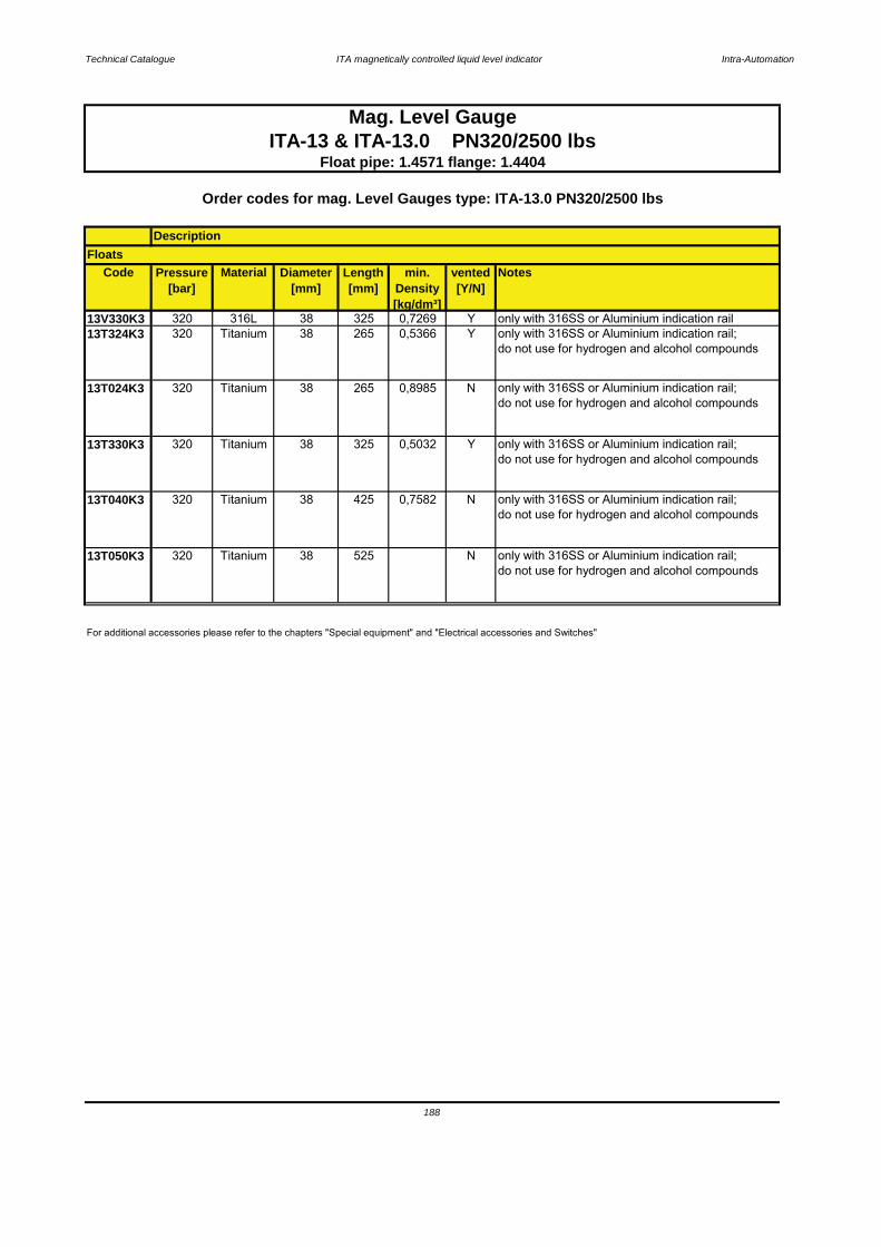
Technical Catalogue ITA magnetically controlled liquid level indicator Intra-Automation
Code Pressure[bar]
Material Diameter[mm]
Length[mm]
min. Density[kg/dm³]
vented[Y/N]
Notes
13V330K3 320 316L 38 325 0,7269 Y only with 316SS or Aluminium indication rail13T324K3 320 Titanium 38 265 0,5366 Y only with 316SS or Aluminium indication rail;
do not use for hydrogen and alcohol compounds
13T024K3 320 Titanium 38 265 0,8985 N only with 316SS or Aluminium indication rail;do not use for hydrogen and alcohol compounds
13T330K3 320 Titanium 38 325 0,5032 Y only with 316SS or Aluminium indication rail;do not use for hydrogen and alcohol compounds
13T040K3 320 Titanium 38 425 0,7582 N only with 316SS or Aluminium indication rail;do not use for hydrogen and alcohol compounds
13T050K3 320 Titanium 38 525 N only with 316SS or Aluminium indication rail;do not use for hydrogen and alcohol compounds
188
Mag. Level GaugeITA-13 & ITA-13.0 PN320/2500 lbs
Float pipe: 1.4571 flange: 1.4404
For additional accessories please refer to the chapters "Special equipment" and "Electrical accessories and Switches"
Order codes for mag. Level Gauges type: ITA-13.0 PN320/2500 lbs
DescriptionFloats
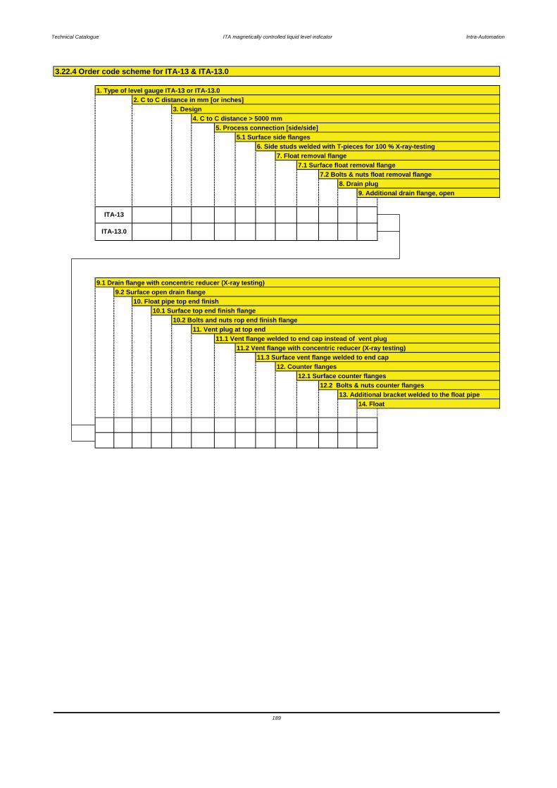
Technical Catalogue ITA magnetically controlled liquid level indicator Intra-Automation
189
12.1 Surface counter flanges12.2 Bolts & nuts counter flanges
13. Additional bracket welded to the float pipe14. Float
10.2 Bolts and nuts rop end finish flange11. Vent plug at top end
11.1 Vent flange welded to end cap instead of vent plug11.2 Vent flange with concentric reducer (X-ray testing)
11.3 Surface vent flange welded to end cap 12. Counter flanges
ITA-13.0
9.1 Drain flange with concentric reducer (X-ray testing)9.2 Surface open drain flange
10. Float pipe top end finish10.1 Surface top end finish flange
9. Additional drain flange, open
ITA-13
7.2 Bolts & nuts float removal flange8. Drain plug
7. Float removal flange7.1 Surface float removal flange
5.1 Surface side flanges6. Side studs welded with T-pieces for 100 % X-ray-testing
4. C to C distance > 5000 mm5. Process connection [side/side]
3.22.4 Order code scheme for ITA-13 & ITA-13.0
1. Type of level gauge ITA-13 or ITA-13.02. C to C distance in mm [or inches]
3. Design
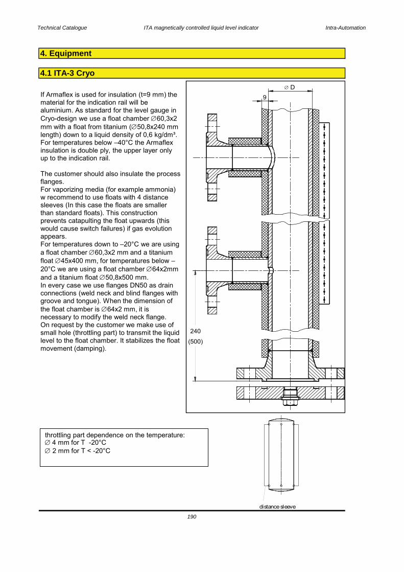
Technical Catalogue ITA magnetically controlled liquid level indicator Intra-Automation
4. Equipment
4.1 ITA-3 Cryo
190
240
(500)
9
DIf Armaflex is used for insulation (t=9 mm) the material for the indication rail will be aluminium. As standard for the level gauge in Cryo-design we use a float chamber 60,3x2 mm with a float from titanium ( 50,8x240 mm length) down to a liquid density of 0,6 kg/dm³.For temperatures below –40°C the Armaflex insulation is double ply, the upper layer only up to the indication rail.
The customer should also insulate the process flanges.For vaporizing media (for example ammonia) w recommend to use floats with 4 distance sleeves (In this case the floats are smaller than standard floats). This construction prevents catapulting the float upwards (this would cause switch failures) if gas evolution appears.For temperatures down to –20°C we are using a float chamber 60,3x2 mm and a titanium float 45x400 mm, for temperatures below –20°C we are using a float chamber 64x2mm and a titanium float 50,8x500 mm.In every case we use flanges DN50 as drain connections (weld neck and blind flanges with groove and tongue). When the dimension of the float chamber is 64x2 mm, it is necessary to modify the weld neck flange.On request by the customer we make use of small hole (throttling part) to transmit the liquid level to the float chamber. It stabilizes the float movement (damping).
distance sleeve
throttling part dependence on the temperature:4 mm for T -20°C2 mm for T < -20°C
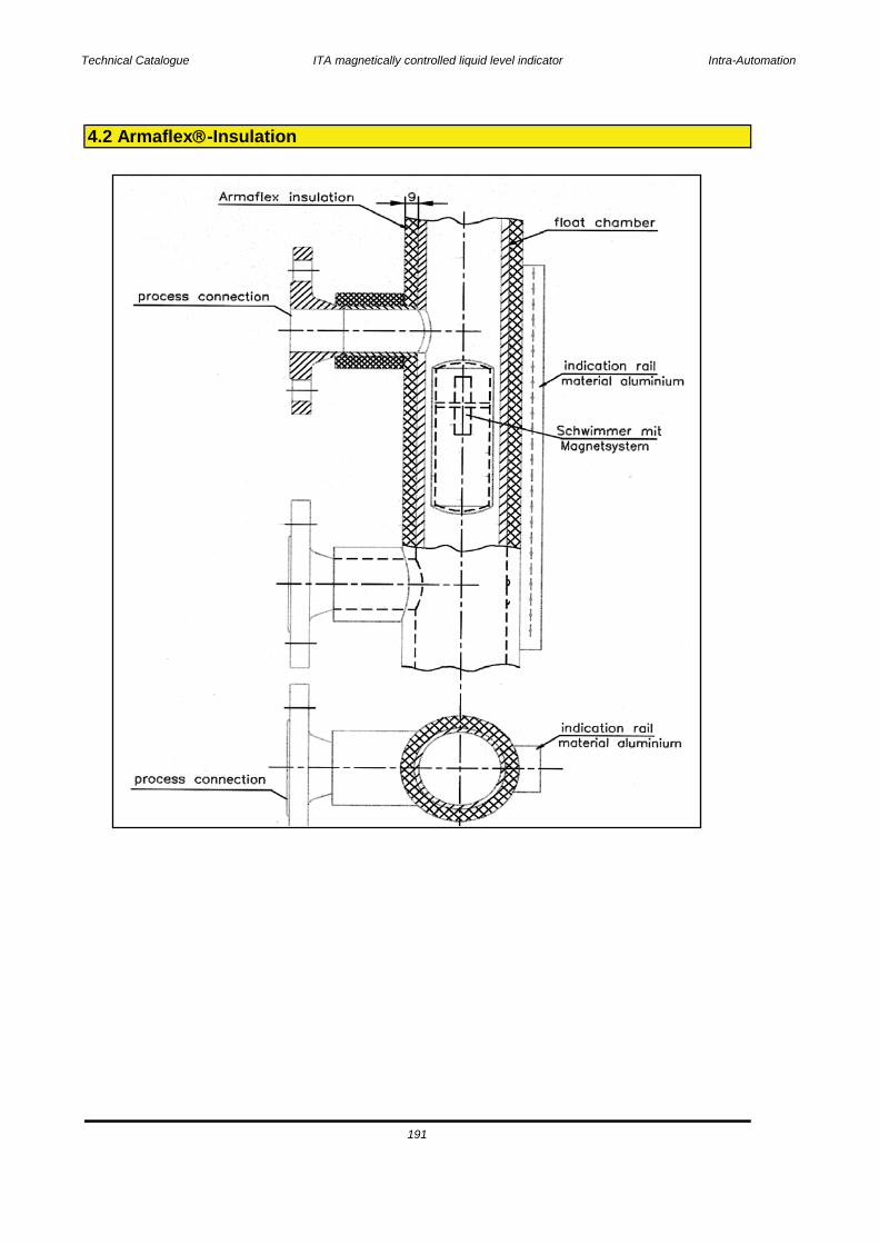
Technical Catalogue ITA magnetically controlled liquid level indicator Intra-Automation
191
4.2 Armaflex -Insulation

Technical Catalogue ITA magnetically controlled liquid level indicator Intra-Automation
Isolation and sealing material:made of e-glassyarns
Technical data:Composition in %: : 53 % SiO2, 16 % CaO, 13 % Al2O3, 7 % B2O3,
4 % MgO, 1 % Na2 + K2OPortion organic substance : < 1 % (combust at first heating-up)Density (g/cm³) : 2,5Temperature resistance : 500°C/550°CDegree of moisture : 1%Annealing loss : 0,6%Shrinking : 500°C = 0 %Resistance against : Oil, grease, water, temporary steam
and numerous organic acids/solvents.Good resistance against sudden heat waves. Goodthermal electrical and acoustical insulationresistance:Toxicologically harmlessNo handling abligations
4.3 Heat insulation
192
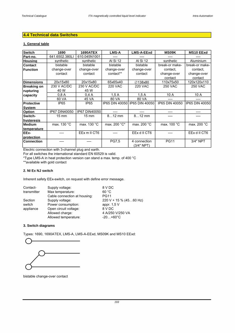
Technical Catalogue ITA magnetically controlled liquid level indicator Intra-Automation
1. General table
Switch 1690 1690ATEX LMS-A LMS-A-EExd MS09K MS10 EExdPart-no. 641.6502.380LI 610.045N1001 ---- ---- ---- ----Housing synthetic synthetic Al Si 12 Al Si 12 synthetic AluminiumContactFunction
bistablechange-over
contact
bistablechange-over
contact
bistablechange-over
contact**
bistablechange-over
contact
break-or make-contact,
change-overcontact
break-or make-contact,
change-overcontact
Dimensions 20x15x80 20x15x80 65x65x40 138x80 110x75x50 120x120x110230 V AC/DC
40 W230 V AC/DC
45 W220 VAC 220 VAC 250 VAC 250 VAC
0,8 A 0,4 A 1,5 A 1,5 A 10 A 10 A60 VA 45 VA 80 VA 80 VA ---- ----
ProtectiveSystem
IP65 IP65 IP65 DIN 40050 IP65 DIN 40050 IP65 DIN 40050 IP65 DIN 40050
Option IP67 DIN40050 IP67 DIN40050 ---- ---- ---- ----Switch-hysteresis
15 mm 15 mm 8…12 mm 8…12 mm ---- ----
Mediumtemperature
max. 130 °C max. 130 °C max. 200 °C* max. 200 °C max. 100 °C max. 200 °C
EEx-protection
---- EEx m II CT6 ---- EEx d II CT6 ---- EEx d II CT6
Connection ---- ---- PG7,5 4 connection(3/4" NPT)
PG11 3/4" NPT
Electric connection with 3-channel plug and earth.For all switches the international standard EN 60529 is valid.*Type LMS-A in heat protection version can stand a max. temp. of 400 °C**available with gold contact
2. NI Ex NJ switch
Inherent safety EEx-switch, on request with define error message.
Contact-transmitter
Sectionswitchappliance
3. Switch diagrams
Types: 1690, 1690ATEX, LMS-A, LMS-A-EExd, MS09K and MS10 EExd:
bistable change-over contact
appr. 1,5 V8 V DC
4.4 Technical data Switches
Breaking onrupturingcapacity
8 V DC60 °CPG11220 V + 15 % (45…60 Hz)
4 A/250 V/250 VA-20…+60°C
Allowed charge:Allowed temperature:
Supply voltage:Max temperature:Cable connection at housing:Supply voltage:Power consumption:Open circuit voltage:
193
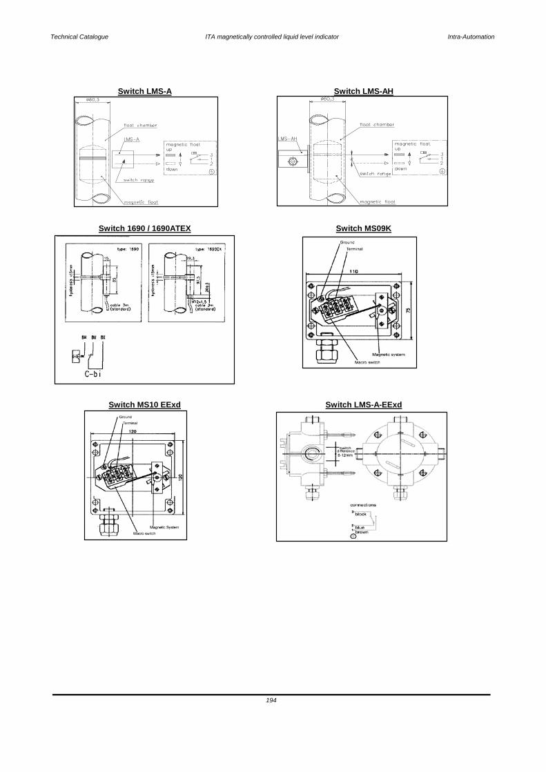
Technical Catalogue ITA magnetically controlled liquid level indicator Intra-Automation
Switch MS10 EExd Switch LMS-A-EExd
194
Switch LMS-A Switch LMS-AH
Switch 1690 / 1690ATEX Switch MS09K
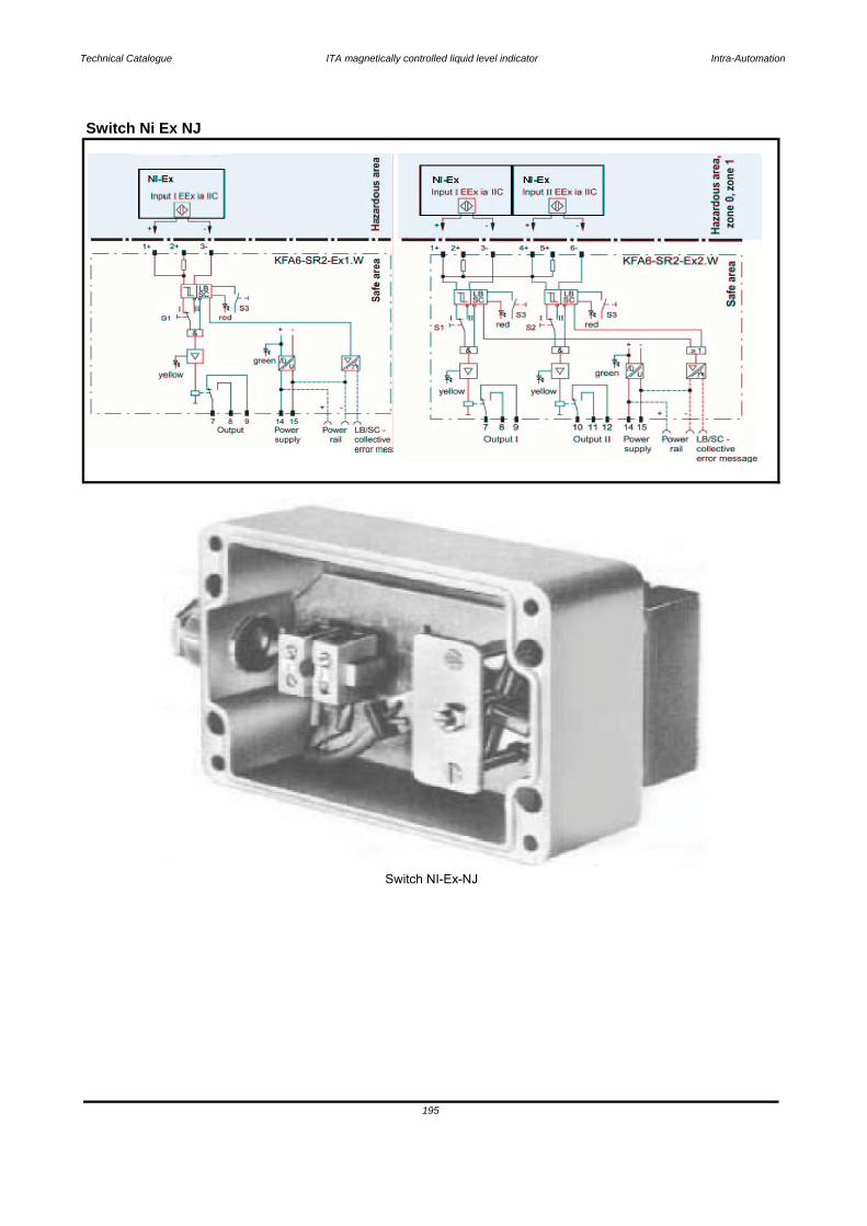
Technical Catalogue ITA magnetically controlled liquid level indicator Intra-Automation
Switch Ni Ex NJ
Switch NI-Ex-NJ
195
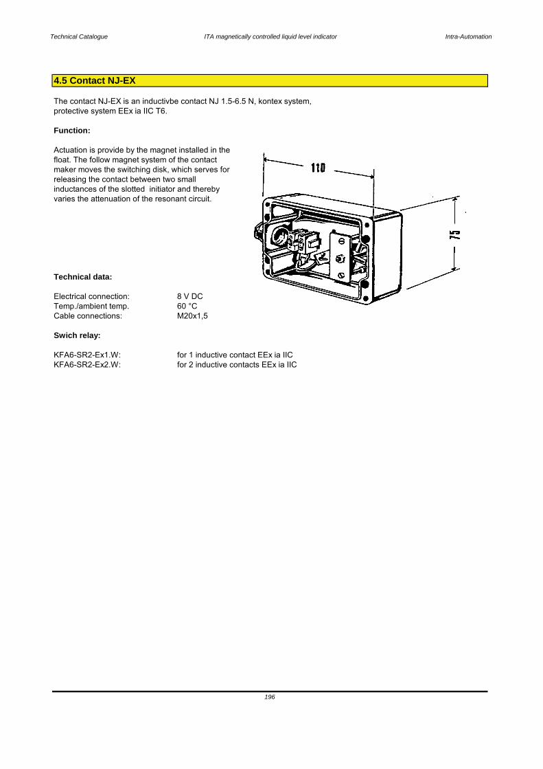
Technical Catalogue ITA magnetically controlled liquid level indicator Intra-Automation
The contact NJ-EX is an inductivbe contact NJ 1.5-6.5 N, kontex system, protective system EEx ia IIC T6.
Function:
Actuation is provide by the magnet installed in the float. The follow magnet system of the contactmaker moves the switching disk, which serves forreleasing the contact between two smallinductances of the slotted initiator and therebyvaries the attenuation of the resonant circuit.
Technical data:
Electrical connection: 8 V DCTemp./ambient temp. 60 °CCable connections: M20x1,5
Swich relay:
KFA6-SR2-Ex1.W: for 1 inductive contact EEx ia IICKFA6-SR2-Ex2.W: for 2 inductive contacts EEx ia IIC
4.5 Contact NJ-EX
196
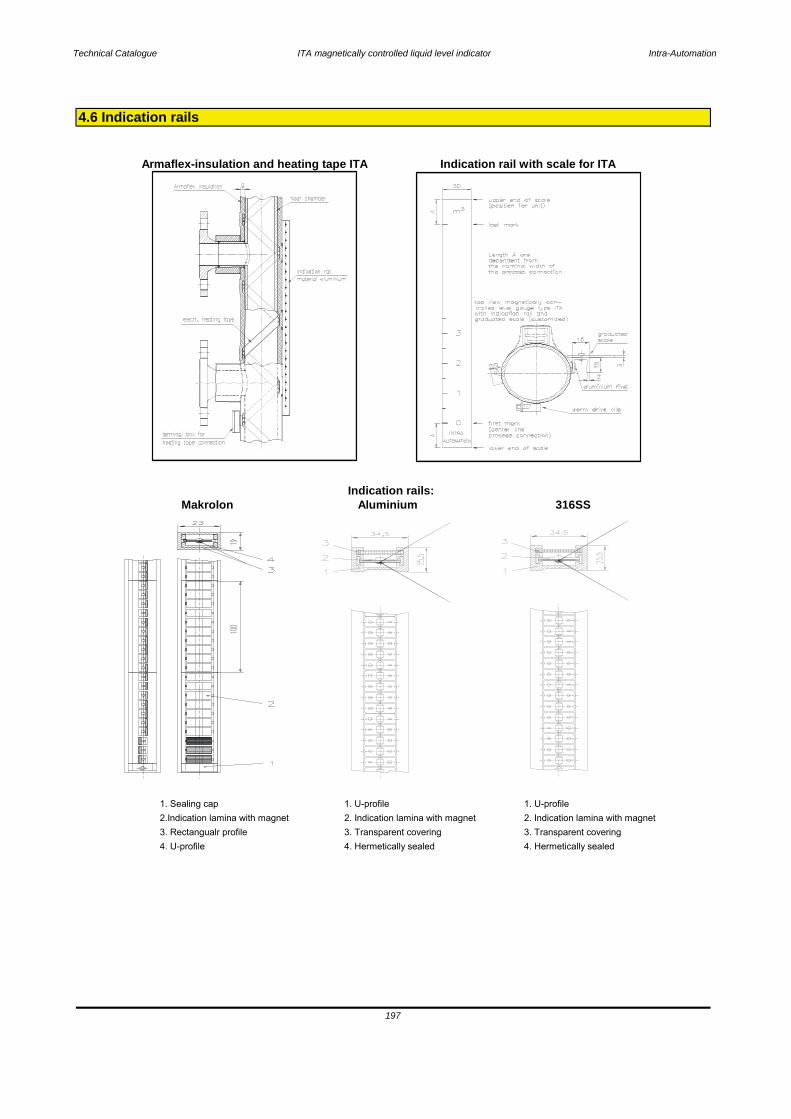
Technical Catalogue ITA magnetically controlled liquid level indicator Intra-Automation
Makrolon Aluminium 316SS
1. Sealing cap 1. U-profile 1. U-profile2.Indication lamina with magnet 2. Indication lamina with magnet 2. Indication lamina with magnet3. Rectangualr profile 3. Transparent covering 3. Transparent covering4. U-profile 4. Hermetically sealed 4. Hermetically sealed
Indication rail with scale for ITAArmaflex-insulation and heating tape ITA
Indication rails:
197
4.6 Indication rails
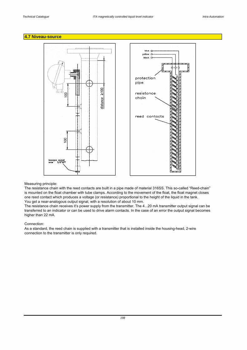
Technical Catalogue ITA magnetically controlled liquid level indicator Intra-Automation
The resistance chain with the reed contacts are built in a pipe made of material 316SS. This so-called “Reed-chain” is mounted on the float chamber with tube clamps. According to the movement of the float, the float magnet closes one reed contact which produces a voltage (or resistance) proportional to the height of the liquid in the tank. You get a near-analogous output signal, with a resolution of about 10 mm.The resistance chain receives it’s power supply from the transmitter. The 4...20 mA transmitter output signal can be transferred to an indicator or can be used to drive alarm contacts. In the case of an error the output signal becomes higher than 22 mA.
As a standard, the reed chain is supplied with a transmitter that is installed inside the housing-head, 2-wire connection to the transmitter is only required.
Connection:
4.7 Niveau-source
Measuring principle:
198
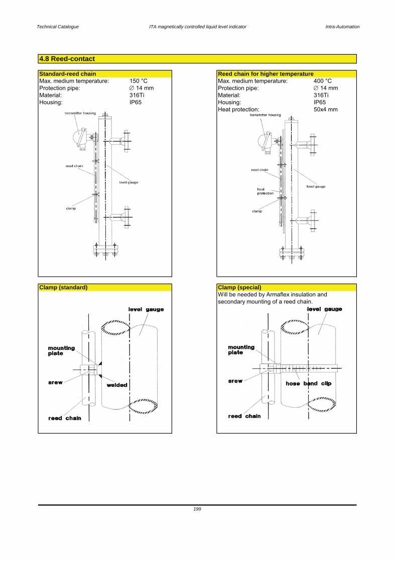
Technical Catalogue ITA magnetically controlled liquid level indicator Intra-Automation
Max. medium temperature: 150 °C Max. medium temperature: 400 °CProtection pipe: 14 mm Protection pipe: 14 mmMaterial: 316Ti Material: 316TiHousing: IP65 Housing: IP65
Heat protection: 50x4 mm
Will be needed by Armaflex insulation and secondary mounting of a reed chain.
Clamp (standard) Clamp (special)
199
4.8 Reed-contact
Standard-reed chain Reed chain for higher temperature
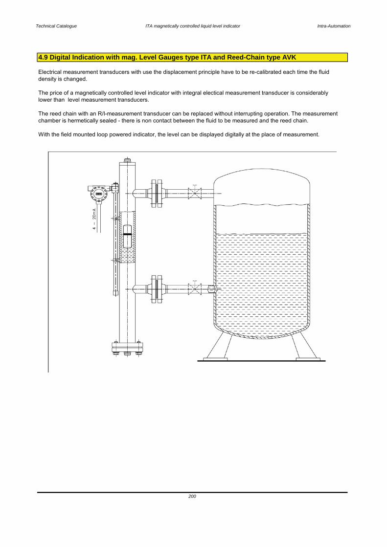
Technical Catalogue ITA magnetically controlled liquid level indicator Intra-Automation
With the field mounted loop powered indicator, the level can be displayed digitally at the place of measurement.
200
Electrical measurement transducers with use the displacement principle have to be re-calibrated each time the fluiddensity is changed.
The price of a magnetically controlled level indicator with integral electical measurement transducer is considerablylower than level measurement transducers.
The reed chain with an R/I-measurement transducer can be replaced without interrupting operation. The measurementchamber is hermetically sealed - there is non contact between the fluid to be measured and the reed chain.
4.9 Digital Indication with mag. Level Gauges type ITA and Reed-Chain type AVK
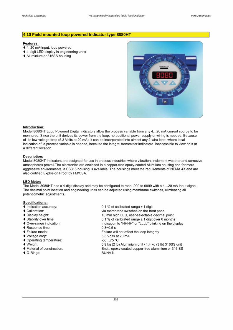
Technical Catalogue ITA magnetically controlled liquid level indicator Intra-Automation
Features: 4..20 mA-input, loop powered 4-digit LED display in engineering units Aluminium or 316SS housing
Introduction:
Description:
LED Meter:The Model 8080HT has a 4-digit display and may be configured to read -999 to 9999 with a 4…20 mA input signal.The decimal point location and engineering units can be adjusted using membrane switches, eliminating allpotentiometric adjustments.
Specifications: Indication accuracy: 0.1 % of calibrated range ± 1 digit Calibration: via membrane switches on the front panel Display height: 10 mm high LED, user-selectable decimal point Stability over time: 0.1 % of calibrated range ± 1 digit over 6 months Over-range indication: Indication fo "HHHH" or "LLLL" blinking on the display Response time: 0.3~0.5 s Failure mode: Failure will not affect the loop integrity Voltage drop: 5.3 Volts at 20 mA Operating temperature: -50…75 °C Weight: 0.9 kg (2 lb) Aluminium unit / 1.4 kg (3 lb) 316SS unit Material of construction: Encl.: epoxy-coated copper-free aluminium or 316 SS O-Rings: BUNA N
201
Model 8080HT Loop Powered Digital Indicators allow the process variable from any 4…20 mA current source to bemonitored. Since the unit derives its power from the loop, no additional power supply or wiring is needed. Because
indication of a process variable is needed, because the integral transmitter indicatore inaccessible to view or is ata different location.
of its low voltage drop (5.3 Volts at 20 mA), it can be incorporated into almost any 2-wire-loop, where local
Model 8080HT Indicators are designed for use in process industries where vibration, inclement weather and corrosiveatmospheres prevail.The electronics are enclosed in a copper-free epoxy-coated Alumiium housing and for more
4.10 Field mounted loop powered Indicator type 8080HT
aggressive environments, a SS316 housing is available. The housings meet the requirements of NEMA 4X and arealso certified Explosion Proof by FM/CSA.

Technical Catalogue ITA magnetically controlled liquid level indicator Intra-Automation
Dimensions of the 8080HT field indicator:
202
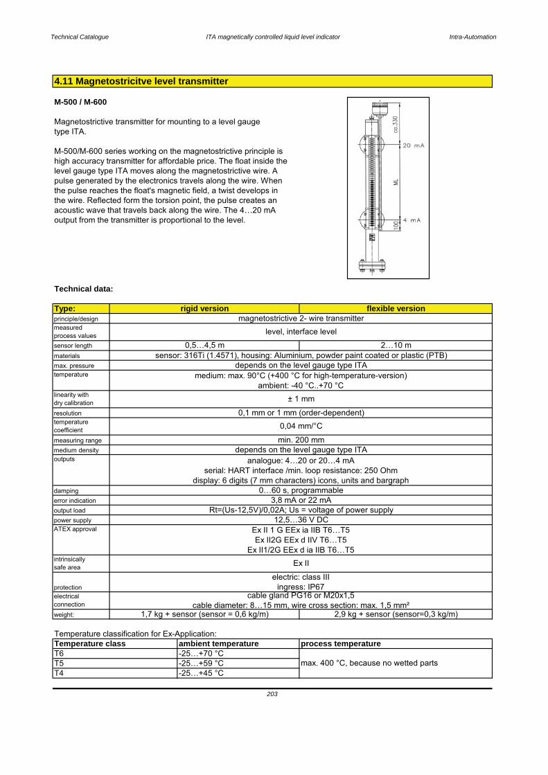
Technical Catalogue ITA magnetically controlled liquid level indicator Intra-Automation
M-500 / M-600
Magnetostrictive transmitter for mounting to a level gauge type ITA.
M-500/M-600 series working on the magnetostrictive principle ishigh accuracy transmitter for affordable price. The float inside thelevel gauge type ITA moves along the magnetostrictive wire. A pulse generated by the electronics travels along the wire. Whenthe pulse reaches the float's magnetic field, a twist develops in the wire. Reflected form the torsion point, the pulse creates an acoustic wave that travels back along the wire. The 4…20 mAoutput from the transmitter is proportional to the level.
Technical data:
Type:principle/designmeasured process valuessensor lengthmaterialsmax. pressuretemperature
linearity with dry calibrationresolutiontemperaturecoefficientmeasuring rangemedium densityoutputs
dampingerror indicationoutput loadpower supplyATEX approval
intrinsically safe area
protectionelectrical connectionweight:
Temperature classification for Ex-Application:
4.11 Magnetostricitve level transmitter
sensor: 316Ti (1.4571), housing: Aluminium, powder paint coated or plastic (PTB)depends on the level gauge type ITA
medium: max. 90°C (+400 °C for high-temperature-version)ambient: -40 °C..+70 °C
± 1 mm
rigid version flexible versionmagnetostrictive 2- wire transmitter
level, interface level
0,5…4,5 m 2…10 m
analogue: 4…20 or 20…4 mAserial: HART interface /min. loop resistance: 250 Ohm
display: 6 digits (7 mm characters) icons, units and bargraph0…60 s, programmable
3,8 mA or 22 mARt=(Us-12,5V)/0,02A; Us = voltage of power supply
0,1 mm or 1 mm (order-dependent)0,04 mm/°C
min. 200 mmdepends on the level gauge type ITA
12,5…36 V DCEx II 1 G EEx ia IIB T6…T5Ex II2G EEx d IIV T6…T5
Ex II1/2G EEx d ia IIB T6…T5Ex II
electric: class IIIingress: IP67
-25…+45 °C
cable gland PG16 or M20x1,5cable diameter: 8…15 mm, wire cross section: max. 1,5 mm²
1,7 kg + sensor (sensor = 0,6 kg/m) 2,9 kg + sensor (sensor=0,3 kg/m)
203
max. 400 °C, because no wetted parts
Temperature class ambient temperatureT6 -25…+70 °C
process temperature
T5 -25…+59 °CT4
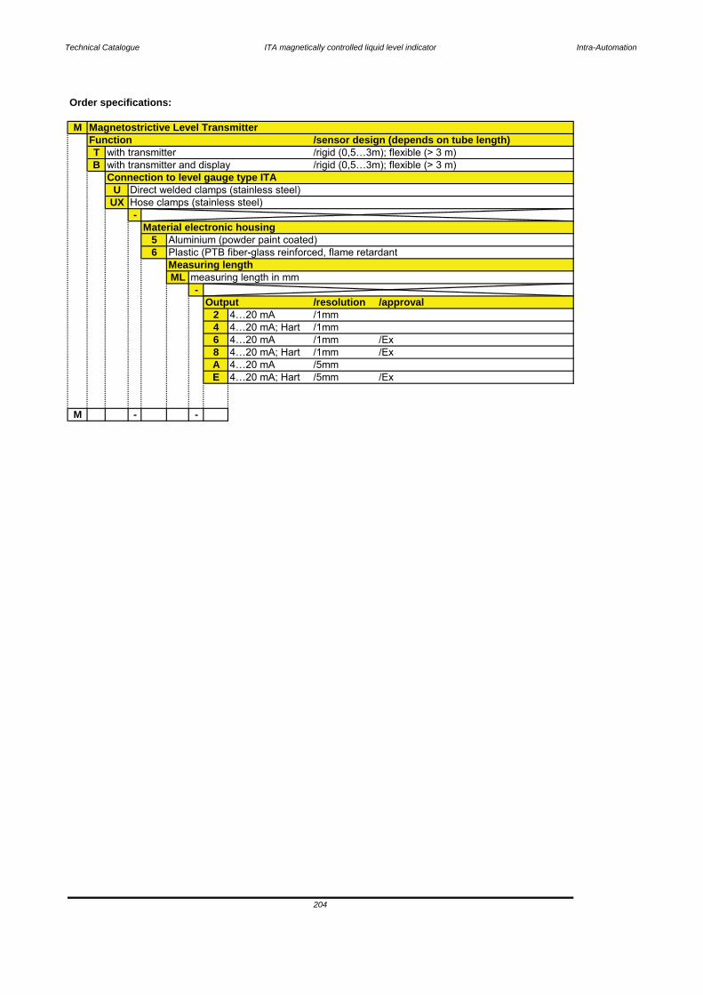
Technical Catalogue ITA magnetically controlled liquid level indicator Intra-Automation
Order specifications:
M
TB
UUX
-
56
ML-
Output /resolution2 4…20 mA /1mm4 4…20 mA; Hart /1mm6 4…20 mA /1mm8 4…20 mA; Hart /1mmA 4…20 mA /5mmE 4…20 mA; Hart /5mm
M - -
with transmitter and display/rigid (0,5…3m); flexible (> 3 m)/rigid (0,5…3m); flexible (> 3 m)
Connection to level gauge type ITA
Magnetostrictive Level TransmitterFunction /sensor design (depends on tube length)
with transmitter
Aluminium (powder paint coated)Plastic (PTB fiber-glass reinforced, flame retardantMeasuring length
measuring length in mm
Direct welded clamps (stainless steel)Hose clamps (stainless steel)
Material electronic housing
204
/Ex/Ex
/approval
/Ex

Technical Catalogue ITA magnetically controlled liquid level indicator Intra-Automation
Available housings Available transmitters
Standard-transmitter- Type: INT5333Bhousing EEx ia IIC T5/T6
material: aluminium output: 4…20 mA PG 16 entry power supply:
2…36 V DC linearity: ± 1 %
EExd-transmitter- Type: TMT182housing EEx ia IIC T4
material: aluminium output: 4…20 mAepoxy coated (Hart-protocol)
1/2" NPT cable entry power supply:13…30 V DC
linearity:
input:
Stainless steeltransmitter housing Other types of transmitters on request!
material: 316Ti M20x1,5 entry
4.12 Transmitters
205

Technical Catalogue ITA magnetically controlled liquid level indicator Intra-Automation
INT53332-wireprogrammable transmitter
RTD or Ohm infput High measurement accuracy 3-wire connection programmable sensor error value for DIN form B sensor head mounting
Application:- Linearized temperature measurement with Pt100…Pt1000 or Ni100…Ni1000
sensor- Conversion of linear resistance variation to a standard analogue current signal,
for instance from valves or Ohmic level sensors.
Technical characteristics:- within a few seconds the user can program the INT5333 to measure temperatures
with all RTD ranges defined by the standards.- The RTD and resistance inputs have cable compensation for 2- and 3-wire
connection.
Mounting/Installation:- For DIN form B sensor head or DIN rail mounting with a special fitting.
2-WIRE PROGRAMMABLE TRANSMITTERINT-5333
Transmitter type INT5333
206
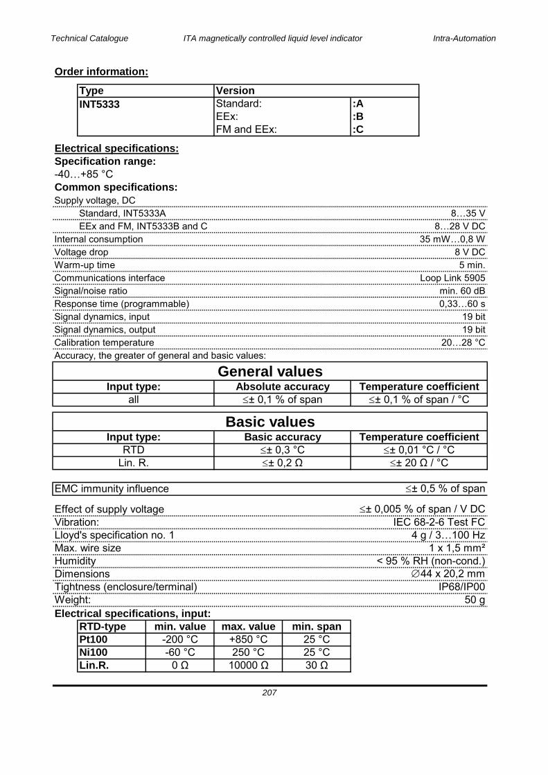
Technical Catalogue ITA magnetically controlled liquid level indicator Intra-Automation
Order information:
:A:B:C
Electrical specifications:Specification range:-40…+85 °CCommon specifications:Supply voltage, DC
Standard, INT5333A 8…35 VEEx and FM, INT5333B and C 8…28 V DC
Internal consumption 35 mW…0,8 WVoltage drop 8 V DCWarm-up time 5 min.Communications interface Loop Link 5905Signal/noise ratio min. 60 dBResponse time (programmable) 0,33…60 sSignal dynamics, input 19 bitSignal dynamics, output 19 bitCalibration temperature 20…28 °CAccuracy, the greater of general and basic values:
EMC immunity influence ± 0,5 % of span
Effect of supply voltage ± 0,005 % of span / V DCVibration: IEC 68-2-6 Test FCLloyd's specification no. 1 4 g / 3…100 HzMax. wire size 1 x 1,5 mm²Humidity < 95 % RH (non-cond.)Dimensions 44 x 20,2 mmTightness (enclosure/terminal) IP68/IP00Weight: 50 gElectrical specifications, input:
RTD-type min. value max. value min. spanPt100 -200 °C +850 °C 25 °CNi100 -60 °C 250 °C 25 °CLin.R.
EEx:
Type Version
FM and EEx:
INT5333
General valuesInput type: Absolute accuracy Temperature coefficient
Standard:
Input type: Basic accuracy Temperature coefficient
all ± 0,1 % of span ± 0,1 % of span / °C
Basic values
207
RTD ± 0,3 °C ± 0,01 °C / °CLin. R.

Technical Catalogue ITA magnetically controlled liquid level indicator Intra-Automation
RTD and linear resistance input:Max. offset 50 % of selected max. valueCable resistance per wire (max.)Sensor current > 0,2 mA < 0,4 mAEffect of sensor cable resistance (3-wire)Sensor error detection Yes
Output:Current output:Signal range 4…20 mAMin signal range 16 mAUpdating time 135 msLoad resistance (Vsupply
Load stability
Sensor error detection:Programmable 3,5…23 mANAMUR NE 43 upscale 23 mANAMUR NE 43 downscale 3,5 mA
Ex data:Ui 28 V DCIi 120 mA DCPi 0,84 WLi 10 μHCi 1 nF
EEx approval CENELEC:DEMKO 03 ATEX 13705XATEXmax. amb. temperature for T1…T4 85 °Cmax. amb. temperature for T5 and T6 60 °CApplicable in zone: 0, 1 or 2FM IS, Cl.I, Div.1 Gp.A-DEntity, FM control drawing no. 5300Q502
Observed authority requirements: Standard:EMC 89/339/EEC
Emission EN50081-1, EN50081-2Immunity EN50082-2, EN50082-1
ATEX 94/9/EC EN50014 and EN50020FM class number 3600, 3610
Of span: of the presently selected range
0539 Ex II 1 GEExia IIC T1…T6
208

Technical Catalogue ITA magnetically controlled liquid level indicator Intra-Automation
Features and benefits:- Universally programmable for various input signals using PROFIBUS-PA .- DIP switch fro address setting (as option)- High accuracy in the total ambient temperature range- EMC to NAMUR NE 21, CE- Certification:
- ATEX- FM- CSA
- PROFIBUS-PA profile V3.0- Galvanic isolation- Customer specific address setting or expanded setup (see questionnaire page)
Application areas:- Applied in a PROFIBUS-PA environment, the process industry fieldbus, an open standard to
EN50170 and IEC 61158-2- Temperature head transmitter with PROFIBUS-PA protocol for converting various input signals
into a ditigal output signal- Input:
- Resistance thermometer (RTD)- Thermocouple (TC)
- Voltage transmitter (mV)- Swift and easy operation, visualization and maintenance using a PC direct from the control panel,
e.g. using the COMMUWIN II operation software.
Transmitter type TMT84 (Profibus)
Resistance transmitterType: TMT84
209
Head transmitter with Profibus-PA interface. Supply and digital communication usingPROFIBUS-PA , for installation in a form B sensor head.
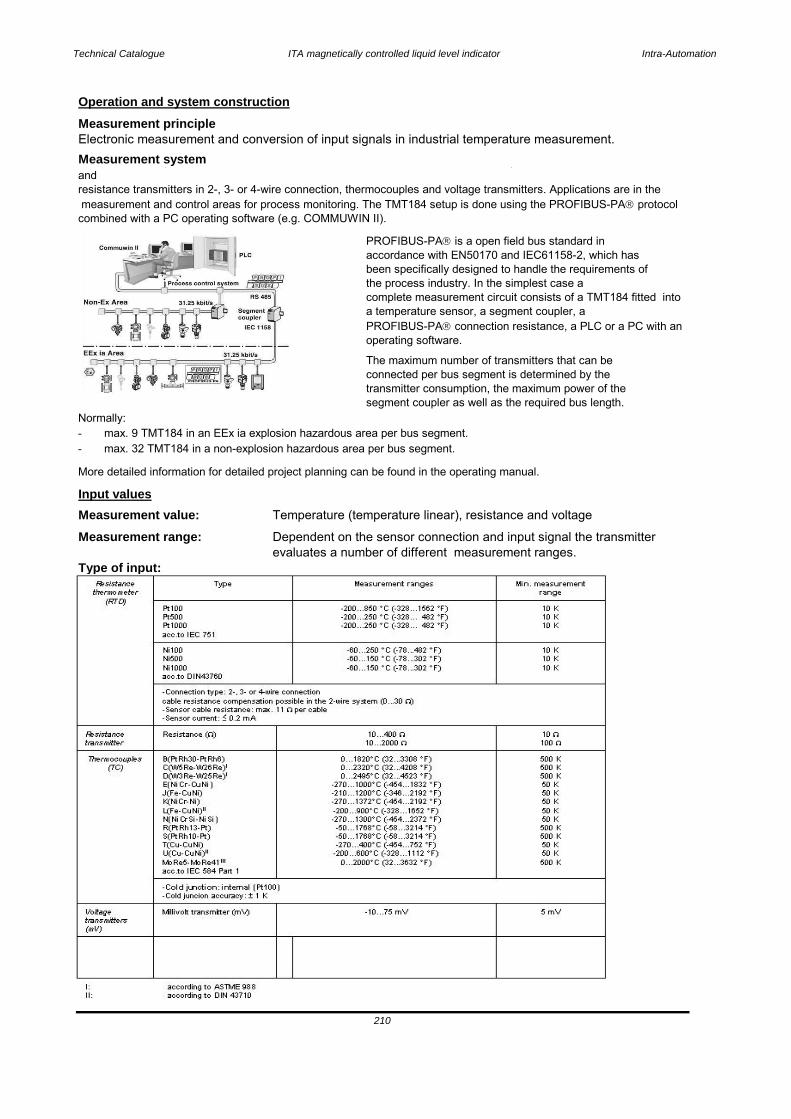
Technical Catalogue ITA magnetically controlled liquid level indicator Intra-Automation
Operation and system constructionMeasurement principle
Measurement system
Normally:- max. 9 TMT184 in an EEx ia explosion hazardous area per bus segment.- max. 32 TMT184 in a non-explosion hazardous area per bus segment.
More detailed information for detailed project planning can be found in the operating manual.
Input valuesMeasurement value: Temperature (temperature linear), resistance and voltage
Measurement range: Dependent on the sensor connection and input signal the transmitterevaluates a number of different measurement ranges.
Type of input:
210
Electronic measurement and conversion of input signals in industrial temperature measurement.
p pandresistance transmitters in 2-, 3- or 4-wire connection, thermocouples and voltage transmitters. Applications are in the measurement and control areas for process monitoring. The TMT184 setup is done using the PROFIBUS-PA protocolcombined with a PC operating software (e.g. COMMUWIN II).
PROFIBUS-PA is a open field bus standard in accordance with EN50170 and IEC61158-2, which has been specifically designed to handle the requirements ofthe process industry. In the simplest case a complete measurement circuit consists of a TMT184 fitted into a temperature sensor, a segment coupler, aPROFIBUS-PA connection resistance, a PLC or a PC with an operating software.
The maximum number of transmitters that can be connected per bus segment is determined by the transmitter consumption, the maximum power of thesegment coupler as well as the required bus length.
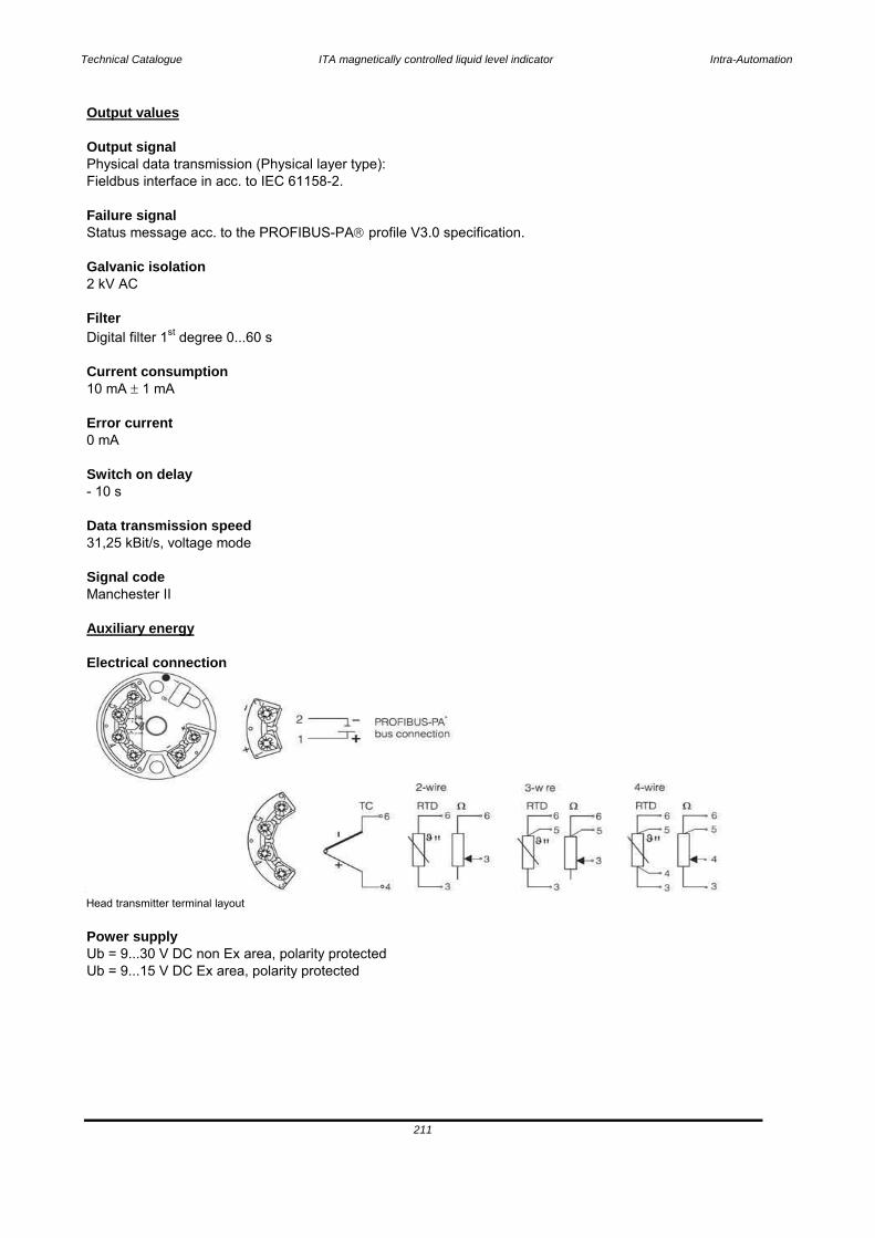
Technical Catalogue ITA magnetically controlled liquid level indicator Intra-Automation
Output values
Output signal
Failure signal
Galvanic isolation
Filter
Current consumption
Error current
Switch on delay
Data transmission speed
Signal code
Electrical connection
Head transmitter terminal layout
Power supply
Status message acc. to the PROFIBUS-PA profile V3.0 specification.
10 mA 1 mA
0 mA
Physical data transmission (Physical layer type):
- 10 s
31,25 kBit/s, voltage mode
211
2 kV AC
Digital filter 1st degree 0...60 s
Fieldbus interface in acc. to IEC 61158-2.
Manchester II
Auxiliary energy
Ub = 9...30 V DC non Ex area, polarity protectedUb = 9...15 V DC Ex area, polarity protected
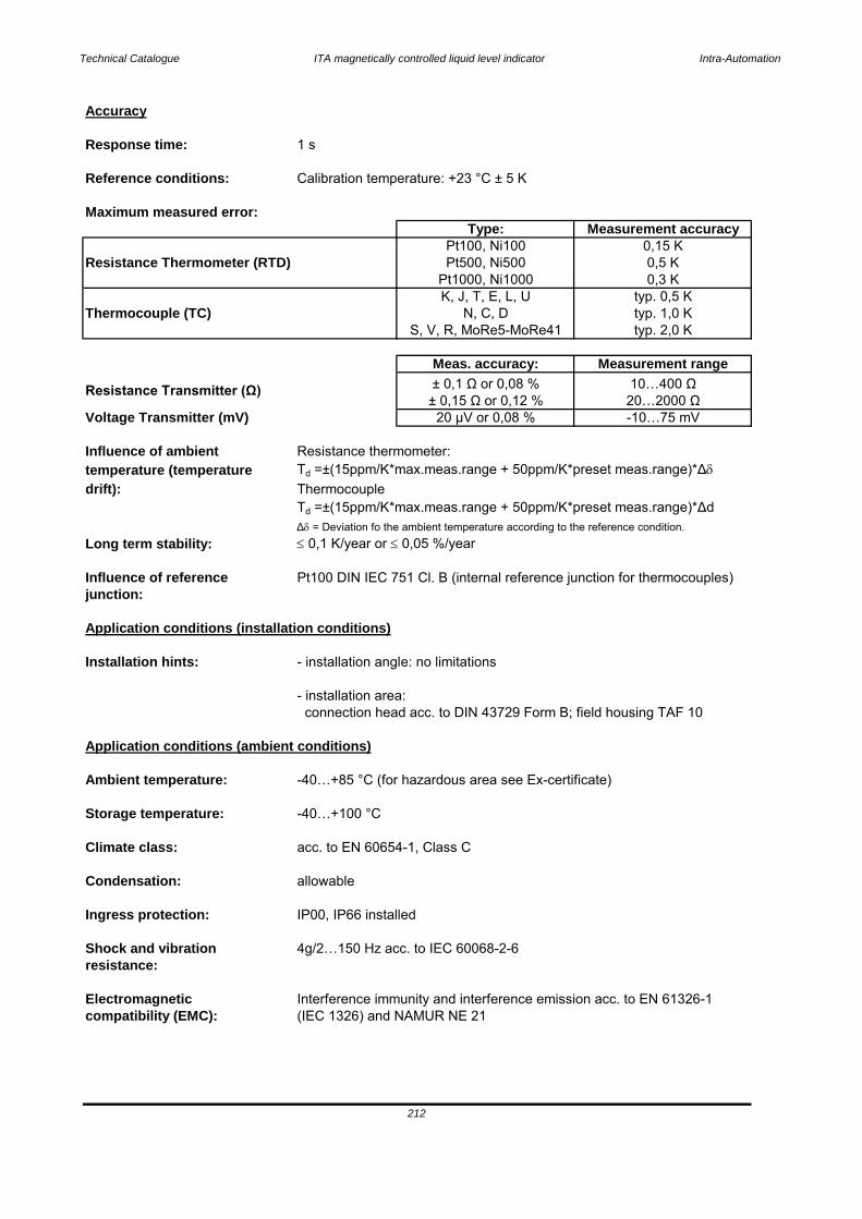
Technical Catalogue ITA magnetically controlled liquid level indicator Intra-Automation
Accuracy
Response time: 1 s
Reference conditions: Calibration temperature: +23 °C ± 5 K
Maximum measured error:
Resistance Thermometer (RTD)
Thermocouple (TC)
Voltage Transmitter (mV)
Influence of ambient Resistance thermometer:temperature (temperature Td
drift): ThermocoupleTd
= Deviation fo the ambient temperature according to the reference condition.Long term stability: 0,1 K/year or 0,05 %/year
Influence of reference Pt100 DIN IEC 751 Cl. B (internal reference junction for thermocouples)junction:
Application conditions (installation conditions)
Installation hints: - installation angle: no limitations
- installation area: connection head acc. to DIN 43729 Form B; field housing TAF 10
Application conditions (ambient conditions)
Ambient temperature: -40…+85 °C (for hazardous area see Ex-certificate)
Storage temperature: -40…+100 °C
Climate class: acc. to EN 60654-1, Class C
Condensation: allowable
Ingress protection: IP00, IP66 installed
Shock and vibration 4g/2…150 Hz acc. to IEC 60068-2-6resistance:
Electromagnetic Interference immunity and interference emission acc. to EN 61326-1compatibility (EMC): (IEC 1326) and NAMUR NE 21
20 μV or 0,08 % -10…75 mV
212
Type: Measurement accuracyPt100, Ni100 0,15 K
K, J, T, E, L, U typ. 0,5 KN, C, D typ. 1,0 K
Pt500, Ni500 0,5 KPt1000, Ni1000 0,3 K
S, V, R, MoRe5-MoRe41 typ. 2,0 K
Meas. accuracy: Measurement range
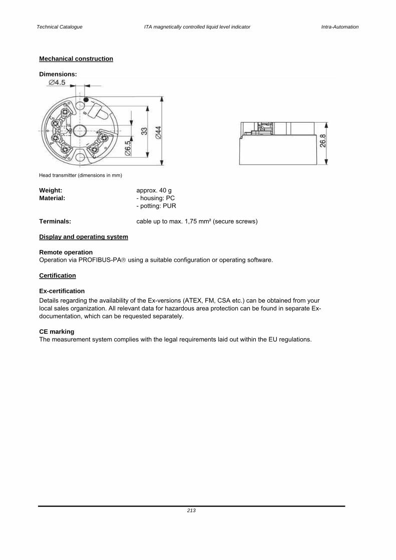
Technical Catalogue ITA magnetically controlled liquid level indicator Intra-Automation
Mechanical construction
Dimensions:
Head transmitter (dimensions in mm)
Weight: approx. 40 gMaterial: - housing: PC
- potting: PUR
Terminals: cable up to max. 1,75 mm² (secure screws)
Display and operating system
Remote operationOperation via PROFIBUS-PA using a suitable configuration or operating software.
Certification
Ex-certification
CE markingThe measurement system complies with the legal requirements laid out within the EU regulations.
213
Details regarding the availability of the Ex-versions (ATEX, FM, CSA etc.) can be obtained from your local sales organization. All relevant data for hazardous area protection can be found in separate Ex-documentation, which can be requested separately.
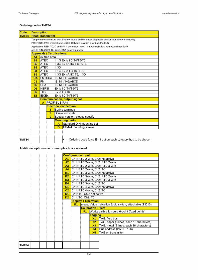
Technical Catalogue ITA magnetically controlled liquid level indicator Intra-Automation
Ordering codes TMT84:
CodeTMT84
A1B1B2B3B4B5CAC1C2D1D2E1
A
129
AB
TMT84 <== Ordering code [part 1] - 1 option each category has to be chosen
Additional options- no or multiple choice allowed.
A1A2A3A4B1B2B3B4C1C2D1D2
E1
F1
X1X2X3X4X5
TMT84
ATEXATEXATEX
NEPSI
ATEXFM+CSAFMCSA
Head Transmitter
Approvals / Certifications:ex-free area
II 1G Ex ia IIC T4/T5/T6
Temperature transmitter with 2 sensor inputs and enhanced diagnosis functions for sensor monitoring.PROFIBUS-PA protocol profile 3.01; Galvanic isolation 2 kV (input/output)
acc. to DIN 43729; UL listed, CSA general purpose
ATEX
IS, NI I/1+2/ABCDIS, NI I/1+2/ABCDIS, NI I/1+2/ABCDEx ia IIC T4/T5/T6
II 3G Ex nA IIC T4/T5/T6II 3DII 1G Ex ia IIC T6, II 3DII 3G Ex nA IIC T6, II 3D
Ex ia IIC T6Ex ia IIC T4/T5/T6
Communication, output signalPROFIBUS-PA
TIISIECEx
Mounting partsStandard-DIN mounting setUS-M4 mounting screws
Configuration input:
Electrical connectionSpring terminalsScrew terminalsSpecial version, please specify
Ch1: RTD 3-wire, Ch2: not activeCh1: RTD 3-wire, Ch2: RTD 2-wireCh1: RTD 3-wire, Ch2: RTD 3-wireCh1: RTD 3-wire, Ch2: TC
Ch1: RTD 2-wire, Ch2: not activeCh1: RTD 2-wire, Ch2: RTD 2-wireCh1: RTD 2-wire, Ch2: RTD 3-wireCh1: RTD 2-wire, Ch2: TC
Calibration + TestWorks calibration cert. 6-point (fixed points)
Ch1: RTD 4-wire, Ch2: not activeCh1: RTD 4-wire, Ch2: TCCh1: TC, Ch2: not activeCh1: TC, Ch2: TC
Bus address (PA: 0…126)TAG on transmitter
214
Description
TaggingTAG, field busTAG, paper (3 lines, each 16 characters)TAG, metal (2 lines, each 16 characters)
Display + Operationmeas. Value indication & dip switch, attachable (TID10)
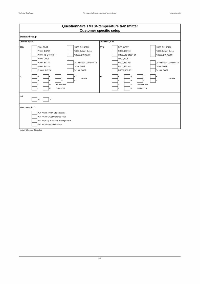
Technical Catalogue ITA magnetically controlled liquid level indicator Intra-Automation
Standard setup
Channel 1 (Ch1) Channel 2, Ch2
RTD Pt50, GOST Ni100, DIN 43760 RTD Pt50, GOST Ni100, DIN 43760
Pt100, IEC751 Ni120, Edison Curve Pt100, IEC751 Ni120, Edison Curve
Pt100, JIS C1604-81 Ni1000, DIN 43760 Pt100, JIS C1604-81 Ni1000, DIN 43760
Pt100, GOST Pt100, GOST
Pt200, IEC 751 Cu10 Edison Curve no. 15 Pt200, IEC 751 Cu10 Edison Curve no. 15
Pt500, IEC 751 Cu50, GOST Pt500, IEC 751 Cu50, GOST
Pt1000, IEC 751 Cu100, GOST Pt1000, IEC 751 Cu100, GOST
TC B E J K TC B E J K
N R S T N R S T
C D ASTM E988 C D ASTM E988
L U DIN 43710 L U DIN 43710
Unit°C °F
Interconnection*
PV1 = Ch1; PV2 = Ch2 (default)
PV1 = Ch1-Ch2; Difference value
PV1 = 0,5 x (Ch1+Ch2), Average value
PV1 = Ch1 (or Ch2) Backup
*only if Channel 2 is active
215
IEC584 IEC584
Questionnaire TMT84 temperature transmitterCustomer specific setup
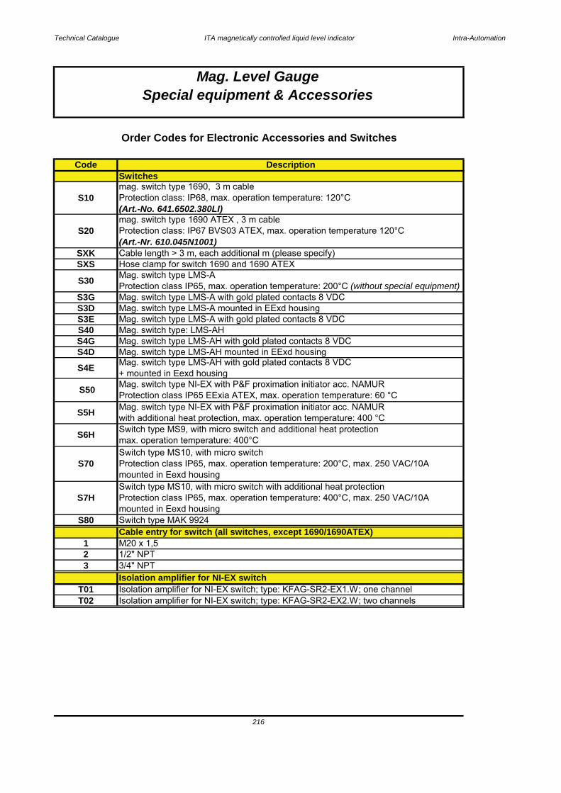
Technical Catalogue ITA magnetically controlled liquid level indicator Intra-Automation
T01 Isolation amplifier for NI-EX switch; type: KFAG-SR2-EX1.W; one channel
Cable entry for switch (all switches, except 1690/1690ATEX)1 M20 x 1,52 1/2" NPT3 3/4" NPT
T02 Isolation amplifier for NI-EX switch; type: KFAG-SR2-EX2.W; two channels
216
Mag. switch type NI-EX with P&F proximation initiator acc. NAMUR Protection class IP65 EExia ATEX, max. operation temperature: 60 °C
S7HSwitch type MS10, with micro switch with additional heat protectionProtection class IP65, max. operation temperature: 400°C, max. 250 VAC/10Amounted in Eexd housing
Isolation amplifier for NI-EX switch
S80 Switch type MAK 9924
Mag. switch type LMS-AProtection class IP65, max. operation temperature: 200°C (without special equipment)
S70Switch type MS10, with micro switch Protection class IP65, max. operation temperature: 200°C, max. 250 VAC/10Amounted in Eexd housing
S5H Mag. switch type NI-EX with P&F proximation initiator acc. NAMUR with additional heat protection, max. operation temperature: 400 °C
S4E Mag. switch type LMS-AH with gold plated contacts 8 VDC + mounted in Eexd housing
S6H Switch type MS9, with micro switch and additional heat protectionmax. operation temperature: 400°C
S50
SXKHose clamp for switch 1690 and 1690 ATEX
S30
Mag. switch type LMS-AH mounted in EExd housing
S3E Mag. switch type LMS-A with gold plated contacts 8 VDC S40 Mag. switch type: LMS-AHS4G Mag. switch type LMS-AH with gold plated contacts 8 VDC
S3D Mag. switch type LMS-A mounted in EExd housing
S4D
Switches
S10
S3G Mag. switch type LMS-A with gold plated contacts 8 VDC
mag. switch type 1690, 3 m cableProtection class: IP68, max. operation temperature: 120°C(Art.-No. 641.6502.380LI)
S20mag. switch type 1690 ATEX , 3 m cableProtection class: IP67 BVS03 ATEX, max. operation temperature 120°C(Art.-Nr. 610.045N1001)Cable length > 3 m, each additional m (please specify)
SXS
Mag. Level GaugeSpecial equipment & Accessories
Order Codes for Electronic Accessories and Switches
Code Description

Technical Catalogue ITA magnetically controlled liquid level indicator Intra-Automation
217
D21
3
D11 Digital indicator mounted in transmitter housing (only with reed-chain) DSM-40-indicator, standard version input 4-20 mA; display ± 19999; EEx-version
D23 Digital indicator IA-N30U, input 4-20 mA; 24 VDC for 2-wire-transmittersadd. 2 off contacs and 4-20 mA-output
M33
Digital indicator IA-N30U, input 4-20 mA; 24 VDC for 2-wire-transmittersadd. 4-20 mA-output
D22 Digital indicator IA-N30U, input 4-20 mA; 24 VDC for 2-wire-transmittersadd- 2 off. contacts
1 M20 x 1,5
D20 Digital indicator IA-N24-S, input 4-20 mA; 24 VDC for 2-wire-transmitters
2 1/2" NPT
M32 Transmitter type: INT5335B Ex-proof with SMART/HART-technologywith stainless steel housing
Digital indicator
M36 Transmitter type STT 3000 with digital indicatorelectr. Class EExd; output 4…20 mA
Transmitter type: INT5350B with Foundation Fieldbus
M34 Transmitter type: TMT142 with Foundation Fieldbus and digital indicatorTransmitter type: INT5350B with Foundation Fieldbus; EExia ATEX
M11 Transmitter type: INT5333A with ExD-housing
Transmitter type: INT5333B EX intrinsically safe with stainless steel housing
Cable entry for transmitter housings
0 without Ex-protection1 EExia ATEX
M35
M30 Transmitter type: INT5335A SMART/HART-technology
M12 Transmitter type: INT5333A with stainless steel housingM20 Transmitter type: INT5333B EX intrinsically safeM22
H with heat protection, max 400 °C / each 100 mmClamps for reed chain / 2 pcs.
Transmitter type: INT5333ATransmitter
RXS
M10
Mag. Level GaugeSpecial equipment & Accessories
Reed chain, resolution 10 mm, max. 150 °C, base price
without heat protection
R20 Reed chain, resolution 20 mm, base priceL add. price each 100 mm0
H with heat protection, max 400 °C / each 100 mm0 without heat protection
with heat protection, max 400 °C / each 100 mmR10
L add. price each 100 mm
H
R05 Reed chain, resolution 5 mm, base priceL add. price each 100 mm0 without heat protection
Reed chainCode Description
Order Codes for Electronic Accessories and Switches
3/4" NPT
D10 Digital indicator mounted in transmitter housing (only with reed-chain) DSM-40-indicator, standard version input 4-20 mA; display ± 19999

Technical Catalogue ITA magnetically controlled liquid level indicator Intra-Automation
Z11 Vent-/drain ball valve 1/2" NPT / material 1.4401
Z13 Vent-/drain valve 1/2" NPT / material: 1.4401Insulation
Z15 Low-temperature-insulation with mineral wool with 316SS arming (each 100 mm)
Z14 Low-temperature-insulation Armaflex -75...+105 °C (only available with Aluminium-indication rail and Titanium float) (each 100 mm)
Z16 Heat insulation ceramic tape; op. temperature up to 600 °C (only available with Aluminium-indication rail and Titanium float) (each 100 mm)
Z17 Insulation guide plate*, material 1.4404; height = 80 mm Equipment for Armaflex- or ceramic insulation (each 100 mm)
Z18 Makrolon window for insulation (each 100 mm)
Steam jacket
Special equipment & AccessoriesMag. Level Gauge
Order Codes for Electronic Accessories and Switches
H31 Electronic heat tape for high temperature applications (> 200 °C), Ex-Version
Z08 Vent-/drain valve 1/2" NPT / material PTFE
Z12 Vent-/drain valve 1/2" NPT, einseitig geflanscht mit DN 15 PN 16
Z10 Vent-/drain valve 1/2" NPT / material PVDFZ09 Vent-/drain valve 1/2" NPT / material PP
Z02 Graduated scale, graved, material: Aluminium, base priceadd. price each 100 mm:
Code Description
H30 Electronic heat tape for high temperature applications (> 200 °C)
Graduated scale, graved, material: 316SS, base priceadd. price each 100 mm:Z02
H21 Electronic heat tape connection set Ex-versionH22 Electronic heat tape connection socket, material CS / EExd housingH23
SG1 Power supply 220 V / 50 Hz
Electronic heat tape connection set
Measuring scale
Z01
Indication railAluminium indication rail coated (Epoxy-coat: Saekaphen); colour: whiteadd. price each 100 mm
H10 Electronic heat tape without Ex-protection, base priceadd. price each 100 mm
Power supply
H12 Electronic heat tape connection socket, material CS
H20
H11
Electronic heat tape, Ex-versionadd. price each 100 mm
Electronic heat tape thermostat Ex-version
Electronic heat tape
Vent/drain fittingsadd. price each 100 mm:
Z05 Steam jacket, max. 6 bar, threaded connection, material 1.4404 (only available withadd. price each 100 mm:
218
Z06 Steam jacket, max. 6 bar, flanged connection DN 15 PN 16 (1/2" 150#),
Z07 Vent-/drain valve 1/2" NPT / material 1.4401
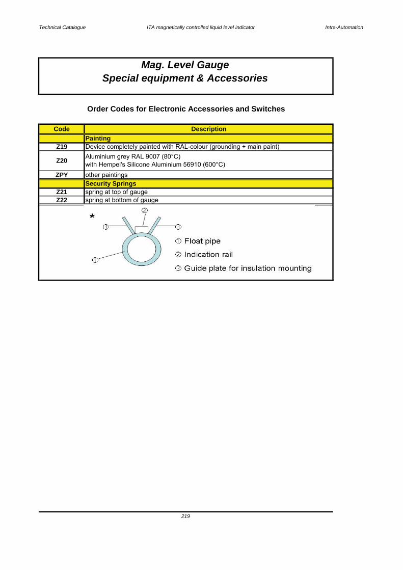
Technical Catalogue ITA magnetically controlled liquid level indicator Intra-Automation
219
Security SpringsZ21 spring at top of gaugeZ22 spring at bottom of gauge
PaintingDevice completely painted with RAL-colour (grounding + main paint)
Order Codes for Electronic Accessories and Switches
ZPY
Code Description
Mag. Level GaugeSpecial equipment & Accessories
other paintings
Z19
Z20 Aluminium grey RAL 9007 (80°C)with Hempel's Silicone Aluminium 56910 (600°C)
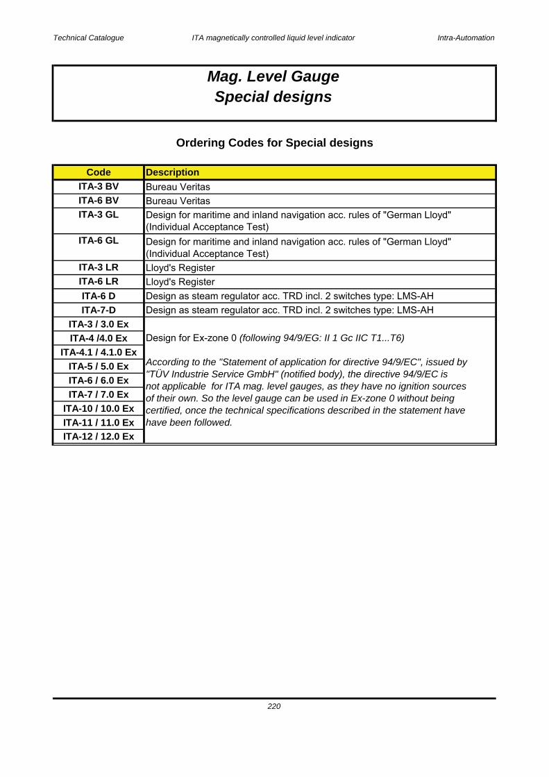
Technical Catalogue ITA magnetically controlled liquid level indicator Intra-Automation
ITA-3 GL Design for maritime and inland navigation acc. rules of "German Lloyd"(Individual Acceptance Test)
ITA-6 / 6.0 ExITA-7 / 7.0 Ex
ITA-12 / 12.0 Ex
Mag. Level GaugeSpecial designs
ITA-4 /4.0 Ex
Code
Ordering Codes for Special designs
ITA-3 BV Bureau Veritas
Design for Ex-zone 0 (following 94/9/EG: II 1 Gc IIC T1...T6)
According to the "Statement of application for directive 94/9/EC", issued by"TÜV Industrie Service GmbH" (notified body), the directive 94/9/EC isnot applicable for ITA mag. level gauges, as they have no ignition sourcesof their own. So the level gauge can be used in Ex-zone 0 without beingcertified, once the technical specifications described in the statement havehave been followed.
Description
ITA-6 BV Bureau Veritas
ITA-5 / 5.0 Ex
ITA-6 GL Design for maritime and inland navigation acc. rules of "German Lloyd"(Individual Acceptance Test)
Design as steam regulator acc. TRD incl. 2 switches type: LMS-AH
ITA-6 LR Lloyd's RegisterITA-3 LR Lloyd's Register
220
Design as steam regulator acc. TRD incl. 2 switches type: LMS-AHITA-7-DITA-6 D
ITA-3 / 3.0 Ex
ITA-10 / 10.0 Ex
ITA-4.1 / 4.1.0 Ex
ITA-11 / 11.0 Ex
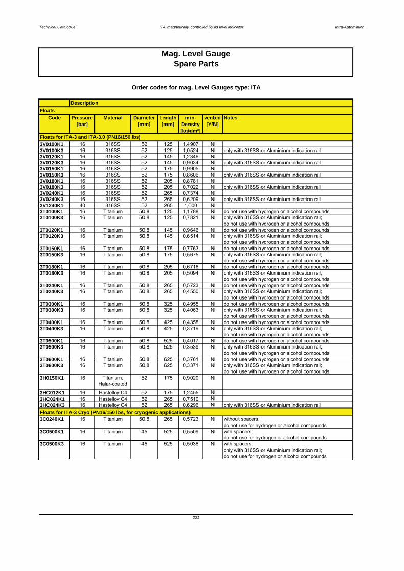
Technical Catalogue ITA magnetically controlled liquid level indicator Intra-Automation
Code Pressure[bar]
Material Diameter[mm]
Length[mm]
min. Density[kg/dm³]
vented[Y/N]
Notes
3V0100K1 16 316SS 52 125 1,4907 N3V0100K3 16 316SS 52 125 1,0524 N only with 316SS or Aluminium indication rail3V0120K1 16 316SS 52 145 1,2346 N3V0120K3 16 316SS 52 145 0,9034 N only with 316SS or Aluminium indication rail3V0150K1 16 316SS 52 175 0,9905 N3V0150K3 16 316SS 52 175 0,8606 N only with 316SS or Aluminium indication rail3V0180K1 16 316SS 52 205 0,8781 N3V0180K3 16 316SS 52 205 0,7022 N only with 316SS or Aluminium indication rail3V0240K1 16 316SS 52 265 0,7374 N3V0240K3 16 316SS 52 265 0,6209 N only with 316SS or Aluminium indication rail3V1240K1 40 316SS 52 265 1,000 N3T0100K1 16 Titanium 50,8 125 1,1788 N do not use with hydrogen or alcohol compounds3T0100K3 16 Titanium 50,8 125 0,7821 N only with 316SS or Aluminium indication rail;
do not use with hydrogen or alcohol compounds3T0120K1 16 Titanium 50,8 145 0,9646 N do not use with hydrogen or alcohol compounds3T0120K3 16 Titanium 50,8 145 0,6514 N only with 316SS or Aluminium indication rail;
do not use with hydrogen or alcohol compounds3T0150K1 16 Titanium 50,8 175 0,7763 N do not use with hydrogen or alcohol compounds3T0150K3 16 Titanium 50,8 175 0,5675 N only with 316SS or Aluminium indication rail;
do not use with hydrogen or alcohol compounds3T0180K1 16 Titanium 50,8 205 0,6716 N do not use with hydrogen or alcohol compounds3T0180K3 16 Titanium 50,8 205 0,5094 N only with 316SS or Aluminium indication rail;
do not use with hydrogen or alcohol compounds3T0240K1 16 Titanium 50,8 265 0,5723 N do not use with hydrogen or alcohol compounds3T0240K3 16 Titanium 50,8 265 0,4550 N only with 316SS or Aluminium indication rail;
do not use with hydrogen or alcohol compounds3T0300K1 16 Titanium 50,8 325 0,4955 N do not use with hydrogen or alcohol compounds3T0300K3 16 Titanium 50,8 325 0,4063 N only with 316SS or Aluminium indication rail;
do not use with hydrogen or alcohol compounds3T0400K1 16 Titanium 50,8 425 0,4358 N do not use with hydrogen or alcohol compounds3T0400K3 16 Titanium 50,8 425 0,3719 N only with 316SS or Aluminium indication rail;
do not use with hydrogen or alcohol compounds3T0500K1 16 Titanium 50,8 525 0,4017 N do not use with hydrogen or alcohol compounds3T0500K3 16 Titanium 50,8 525 0,3539 N only with 316SS or Aluminium indication rail;
do not use with hydrogen or alcohol compounds3T0600K1 16 Titanium 50,8 625 0,3761 N do not use with hydrogen or alcohol compounds3T0600K3 16 Titanium 50,8 625 0,3371 N only with 316SS or Aluminium indication rail;
do not use with hydrogen or alcohol compounds3H0150K1 16 Titanium,
Halar-coated52 175 0,9020 N
3HC012K1 16 Hastelloy C4 52 175 1,2455 N3HC024K1 16 Hastelloy C4 52 265 0,7510 N3HC024K3 16 Hastelloy C4 52 265 0,6296 N only with 316SS or Aluminium indication rail
3C0240K1 16 Titanium 50,8 265 0,5723 N without spacers;do not use for hydrogen or alcohol compounds
3C0500K1 16 Titanium 45 525 0,5509 N with spacers;do not use for hydrogen or alcohol compounds
3C0500K3 16 Titanium 45 525 0,5038 N with spacers; only with 316SS or Aluminium indication rail;do not use for hydrogen or alcohol compounds
Floats for ITA-3 Cryo (PN16/150 lbs, for cryogenic applications)
221
Floats for ITA-3 and ITA-3.0 (PN16/150 lbs)
Order codes for mag. Level Gauges type: ITA
Mag. Level GaugeSpare Parts
DescriptionFloats
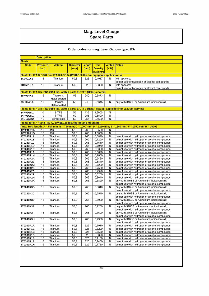
Technical Catalogue ITA magnetically controlled liquid level indicator Intra-Automation
Code Pressure[bar]
Material Diameter[mm]
Length[mm]
min. Density[kg/dm³]
vented[Y/N]
Notes
3C0501K1 16 Titanium 50,8 525 0,4017 N with spacers;do not use for hydrogen or alcohol compounds
3C0501K2 16 Titanium 50,8 525 0,3890 N with spacers;do not use for hydrogen or alcohol compounds
35H024K1 16 Titanium,Halar-coated
52 240 0,6873 N
35H024K3 16 Titanium,Halar-coated
52 240 0,5645 N only with 316SS or Aluminium indication rail
34PVD1K1 10 E-TFE 50 135 1,3000 N34PVD2K1 10 E-TFE 50 255 0,8500 N34GLA2K2 10 Borosilicate 50 255 0,8500 N
4V0240R1A 16 316L 52,0 265 0,9500 N4V0240R1B 16 316L 52,0 265 1,0000 N4T0240R1A 16 Titanium 50,8 265 0,6890 N do not use with hydrogen or alcohol compounds4T0240R1B 16 Titanium 50,8 265 0,7250 N do not use with hydrogen or alcohol compounds4T0240R1C 16 Titanium 50,8 265 0,7610 N do not use with hydrogen or alcohol compounds4T0240R1D 16 Titanium 50,8 265 0,7970 N do not use with hydrogen or alcohol compounds4T0240R1E 16 Titanium 50,8 265 0,8330 N do not use with hydrogen or alcohol compounds4T0240R1F 16 Titanium 50,8 265 0,8690 N do not use with hydrogen or alcohol compounds4T0240R1H 16 Titanium 50,8 265 0,9050 N do not use with hydrogen or alcohol compounds4T0240K2A 16 Titanium 50,8 265 0,6480 N do not use with hydrogen or alcohol compounds4T0240K2B 16 Titanium 50,8 265 0,6840 N do not use with hydrogen or alcohol compounds4T0240K2C 16 Titanium 50,8 265 0,7200 N do not use with hydrogen or alcohol compounds4T0240K2D 16 Titanium 50,8 265 0,7560 N do not use with hydrogen or alcohol compounds4T0240K2E 16 Titanium 50,8 265 0,7920 N do not use with hydrogen or alcohol compounds4T0240K2F 16 Titanium 50,8 265 0,8280 N do not use with hydrogen or alcohol compounds4T0240K2H 16 Titanium 50,8 265 0,8640 N do not use with hydrogen or alcohol compounds4T0240K3A 16 Titanium 50,8 265 0,5820 N only with 316SS or Aluminium indication rail;
do not use with hydrogen or alcohol compounds4T0240K3B 16 Titanium 50,8 265 0,6810 N only with 316SS or Aluminium indication rail;
do not use with hydrogen or alcohol compounds4T0240K3C 16 Titanium 50,8 265 0,6540 N only with 316SS or Aluminium indication rail;
do not use with hydrogen or alcohol compounds4T0240K3D 16 Titanium 50,8 265 0,6900 N only with 316SS or Aluminium indication rail;
do not use with hydrogen or alcohol compounds4T0240K3E 16 Titanium 50,8 265 0,7260 N only with 316SS or Aluminium indication rail;
do not use with hydrogen or alcohol compounds4T0240K3F 16 Titanium 50,8 265 0,7620 N only with 316SS or Aluminium indication rail;
do not use with hydrogen or alcohol compounds4T0240K3H 16 Titanium 50,8 265 0,7980 N only with 316SS or Aluminium indication rail;
do not use with hydrogen or alcohol compounds4T0300R1A 16 Titanium 50,8 325 0,6010 N do not use with hydrogen or alcohol compounds4T0300R1B 16 Titanium 50,8 325 0,6290 N do not use with hydrogen or alcohol compounds4T0300R1C 16 Titanium 50,8 325 0,6580 N do not use with hydrogen or alcohol compounds4T0300R1D 16 Titanium 50,8 325 0,6870 N do not use with hydrogen or alcohol compounds4T0300R1E 16 Titanium 50,8 325 0,7160 N do not use with hydrogen or alcohol compounds4T0300R1F 16 Titanium 50,8 325 0,7450 N do not use with hydrogen or alcohol compounds4T0300R1H 16 Titanium 50,8 325 0,7730 N do not use with hydrogen or alcohol compounds
Order codes for mag. Level Gauges type: ITA
Description
Floats for ITA-4 and ITA-4.0 (PN16/150 lbs, top-of tank mounting)[max. Rod length: A = 500 mm; B = 750 mm; C = 1000 mm; D = 1250 mm; E = 1500 mm; F = 1750 mm; H = 2000]
222
Mag. Level GaugeSpare Parts
Floats
Floats for ITA-3-CR64 and ITA-3.0-CR64 (PN16/150 lbs, for cryogenic applications)
Floats for ITA-3.5 (PN16/150 lbs, wetted parts E-CTFE (Halar)-coated)
Floats for ITA-3.8 (PN16/150 lbs, wetted parts E-CTFE (Halar)-coated, applicable for vacuum-service)

Technical Catalogue ITA magnetically controlled liquid level indicator Intra-Automation
Code Pressure[bar]
Material Diameter[mm]
Length[mm]
min. Density[kg/dm³]
vented[Y/N]
Notes
4T0300K2A 16 Titanium 50,8 325 0,5680 N do not use with hydrogen or alcohol compounds4T0300K2B 16 Titanium 50,8 325 0,5970 N do not use with hydrogen or alcohol compounds4T0300K2C 16 Titanium 50,8 325 0,6250 N do not use with hydrogen or alcohol compounds4T0300K2D 16 Titanium 50,8 325 0,6540 N do not use with hydrogen or alcohol compounds4T0300K2E 16 Titanium 50,8 325 0,6830 N do not use with hydrogen or alcohol compounds4T0300K2F 16 Titanium 50,8 325 0,7120 N do not use with hydrogen or alcohol compounds4T0300K2H 16 Titanium 50,8 325 0,7410 N do not use with hydrogen or alcohol compounds4T0300K3A 16 Titanium 50,8 325 0,5120 N only with 316SS or Aluminium indication rail;
do not use with hydrogen or alcohol compounds4T0300K3B 16 Titanium 50,8 325 0,5410 N only with 316SS or Aluminium indication rail;
do not use with hydrogen or alcohol compounds4T0300K3C 16 Titanium 50,8 325 0,5690 N only with 316SS or Aluminium indication rail;
do not use with hydrogen or alcohol compounds4T0300K3D 16 Titanium 50,8 325 0,5980 N only with 316SS or Aluminium indication rail;
do not use with hydrogen or alcohol compounds4T0300K3E 16 Titanium 50,8 325 0,6270 N only with 316SS or Aluminium indication rail;
do not use with hydrogen or alcohol compounds4T0300K3F 16 Titanium 50,8 325 0,6560 N only with 316SS or Aluminium indication rail;
do not use with hydrogen or alcohol compounds4T0300K3H 16 Titanium 50,8 325 0,6850 N only with 316SS or Aluminium indication rail;
do not use with hydrogen or alcohol compounds
4T0152R1A ATM Titanium 80 175 0,4070 N do not use with hydrogen or alcohol compounds4T0152R1B ATM Titanium 80 175 0,4310 N do not use with hydrogen or alcohol compounds4T0152R1C ATM Titanium 80 175 0,4540 N do not use with hydrogen or alcohol compounds4T0152R1D ATM Titanium 80 175 0,4770 N do not use with hydrogen or alcohol compounds4T0152R1E ATM Titanium 80 175 0,5000 N do not use with hydrogen or alcohol compounds4T0152R1F ATM Titanium 80 175 0,5240 N do not use with hydrogen or alcohol compounds4T0152R1H ATM Titanium 80 175 0,5470 N do not use with hydrogen or alcohol compounds4T0152K2A ATM Titanium 80 175 0,4700 N do not use with hydrogen or alcohol compounds4T0152K2B ATM Titanium 80 175 0,4310 N do not use with hydrogen or alcohol compounds4T0152K2C ATM Titanium 80 175 0,4540 N do not use with hydrogen or alcohol compounds4T0152K2D ATM Titanium 80 175 0,4770 N do not use with hydrogen or alcohol compounds4T0152K2E ATM Titanium 80 175 0,5000 N do not use with hydrogen or alcohol compounds4T0152K2F ATM Titanium 80 175 0,5240 N do not use with hydrogen or alcohol compounds4T0152K2H ATM Titanium 80 175 0,5470 N do not use with hydrogen or alcohol compounds4T0152K3A ATM Titanium 80 175 0,4710 N only with 316SS or Aluminium indication rail;
do not use with hydrogen or alcohol compounds4T0152K3B ATM Titanium 80 175 0,4940 N only with 316SS or Aluminium indication rail;
do not use with hydrogen or alcohol compounds4T0152K3C ATM Titanium 80 175 0,5180 N only with 316SS or Aluminium indication rail;
do not use with hydrogen or alcohol compounds4T0152K3D ATM Titanium 80 175 0,5410 N only with 316SS or Aluminium indication rail;
do not use with hydrogen or alcohol compounds4T0152K3E ATM Titanium 80 175 0,5640 N only with 316SS or Aluminium indication rail;
do not use with hydrogen or alcohol compounds4T0152K3F ATM Titanium 80 175 0,6870 N only with 316SS or Aluminium indication rail;
do not use with hydrogen or alcohol compounds4T0152K3H ATM Titanium 80 175 0,6100 N only with 316SS or Aluminium indication rail;
do not use with hydrogen or alcohol compounds
Description
Order codes for mag. Level Gauges type: ITA
Mag. Level Gauge
Floats
Spare Parts
Floats for ITA-4 and ITA-4.0 (PN16/150 lbs, top-of tank mounting) (Continuation)[max. Rod length: A = 500 mm; B = 750 mm; C = 1000 mm; D = 1250 mm; E = 1500 mm; F = 1750 mm; H = 2000]
223
Floats for ITA-4.1 and ITA-4.1.0 (atm., top-of tank mounting)[max. Rod length: A = 500 mm; B = 750 mm; C = 1000 mm; D = 1250 mm; E = 1500 mm; F = 1750 mm; H = 2000]
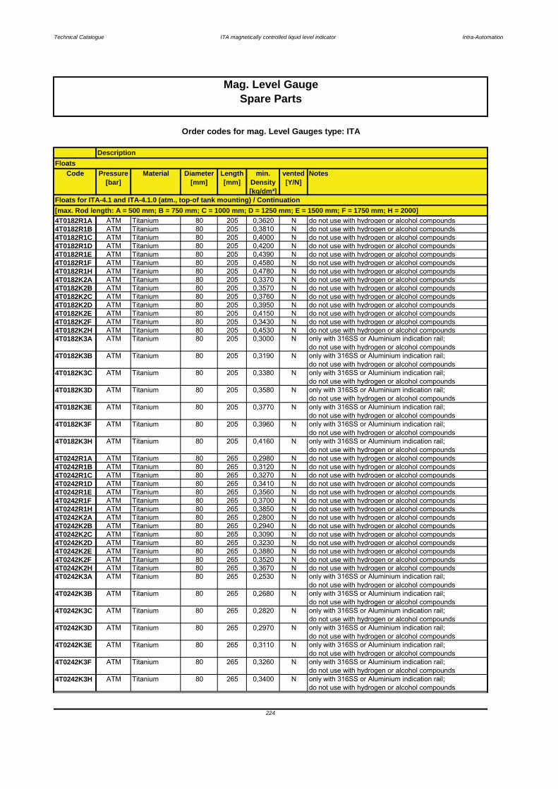
Technical Catalogue ITA magnetically controlled liquid level indicator Intra-Automation
Code Pressure[bar]
Material Diameter[mm]
Length[mm]
min. Density[kg/dm³]
vented[Y/N]
Notes
4T0182R1A ATM Titanium 80 205 0,3620 N do not use with hydrogen or alcohol compounds4T0182R1B ATM Titanium 80 205 0,3810 N do not use with hydrogen or alcohol compounds4T0182R1C ATM Titanium 80 205 0,4000 N do not use with hydrogen or alcohol compounds4T0182R1D ATM Titanium 80 205 0,4200 N do not use with hydrogen or alcohol compounds4T0182R1E ATM Titanium 80 205 0,4390 N do not use with hydrogen or alcohol compounds4T0182R1F ATM Titanium 80 205 0,4580 N do not use with hydrogen or alcohol compounds4T0182R1H ATM Titanium 80 205 0,4780 N do not use with hydrogen or alcohol compounds4T0182K2A ATM Titanium 80 205 0,3370 N do not use with hydrogen or alcohol compounds4T0182K2B ATM Titanium 80 205 0,3570 N do not use with hydrogen or alcohol compounds4T0182K2C ATM Titanium 80 205 0,3760 N do not use with hydrogen or alcohol compounds4T0182K2D ATM Titanium 80 205 0,3950 N do not use with hydrogen or alcohol compounds4T0182K2E ATM Titanium 80 205 0,4150 N do not use with hydrogen or alcohol compounds4T0182K2F ATM Titanium 80 205 0,3430 N do not use with hydrogen or alcohol compounds4T0182K2H ATM Titanium 80 205 0,4530 N do not use with hydrogen or alcohol compounds4T0182K3A ATM Titanium 80 205 0,3000 N only with 316SS or Aluminium indication rail;
do not use with hydrogen or alcohol compounds4T0182K3B ATM Titanium 80 205 0,3190 N only with 316SS or Aluminium indication rail;
do not use with hydrogen or alcohol compounds4T0182K3C ATM Titanium 80 205 0,3380 N only with 316SS or Aluminium indication rail;
do not use with hydrogen or alcohol compounds4T0182K3D ATM Titanium 80 205 0,3580 N only with 316SS or Aluminium indication rail;
do not use with hydrogen or alcohol compounds4T0182K3E ATM Titanium 80 205 0,3770 N only with 316SS or Aluminium indication rail;
do not use with hydrogen or alcohol compounds4T0182K3F ATM Titanium 80 205 0,3960 N only with 316SS or Aluminium indication rail;
do not use with hydrogen or alcohol compounds4T0182K3H ATM Titanium 80 205 0,4160 N only with 316SS or Aluminium indication rail;
do not use with hydrogen or alcohol compounds4T0242R1A ATM Titanium 80 265 0,2980 N do not use with hydrogen or alcohol compounds4T0242R1B ATM Titanium 80 265 0,3120 N do not use with hydrogen or alcohol compounds4T0242R1C ATM Titanium 80 265 0,3270 N do not use with hydrogen or alcohol compounds4T0242R1D ATM Titanium 80 265 0,3410 N do not use with hydrogen or alcohol compounds4T0242R1E ATM Titanium 80 265 0,3560 N do not use with hydrogen or alcohol compounds4T0242R1F ATM Titanium 80 265 0,3700 N do not use with hydrogen or alcohol compounds4T0242R1H ATM Titanium 80 265 0,3850 N do not use with hydrogen or alcohol compounds4T0242K2A ATM Titanium 80 265 0,2800 N do not use with hydrogen or alcohol compounds4T0242K2B ATM Titanium 80 265 0,2940 N do not use with hydrogen or alcohol compounds4T0242K2C ATM Titanium 80 265 0,3090 N do not use with hydrogen or alcohol compounds4T0242K2D ATM Titanium 80 265 0,3230 N do not use with hydrogen or alcohol compounds4T0242K2E ATM Titanium 80 265 0,3880 N do not use with hydrogen or alcohol compounds4T0242K2F ATM Titanium 80 265 0,3520 N do not use with hydrogen or alcohol compounds4T0242K2H ATM Titanium 80 265 0,3670 N do not use with hydrogen or alcohol compounds4T0242K3A ATM Titanium 80 265 0,2530 N only with 316SS or Aluminium indication rail;
do not use with hydrogen or alcohol compounds4T0242K3B ATM Titanium 80 265 0,2680 N only with 316SS or Aluminium indication rail;
do not use with hydrogen or alcohol compounds4T0242K3C ATM Titanium 80 265 0,2820 N only with 316SS or Aluminium indication rail;
do not use with hydrogen or alcohol compounds4T0242K3D ATM Titanium 80 265 0,2970 N only with 316SS or Aluminium indication rail;
do not use with hydrogen or alcohol compounds4T0242K3E ATM Titanium 80 265 0,3110 N only with 316SS or Aluminium indication rail;
do not use with hydrogen or alcohol compounds4T0242K3F ATM Titanium 80 265 0,3260 N only with 316SS or Aluminium indication rail;
do not use with hydrogen or alcohol compounds4T0242K3H ATM Titanium 80 265 0,3400 N only with 316SS or Aluminium indication rail;
do not use with hydrogen or alcohol compounds
Order codes for mag. Level Gauges type: ITA
Mag. Level GaugeSpare Parts
Floats
Floats for ITA-4.1 and ITA-4.1.0 (atm., top-of tank mounting) / Continuation[max. Rod length: A = 500 mm; B = 750 mm; C = 1000 mm; D = 1250 mm; E = 1500 mm; F = 1750 mm; H = 2000]
Description
224

Technical Catalogue ITA magnetically controlled liquid level indicator Intra-Automation
Code Pressure[bar]
Material Diameter[mm]
Length[mm]
min. Density[kg/dm³]
vented[Y/N]
Notes
6V0100K1 30 316L 52 125 1,5188 N6V0100K3 30 316L 52 125 1,0891 N only with 316SS or Aluminium indication rail6V0120K1 30 316L 52 145 1,2780 N6V0120K3 30 316L 52 145 0,9519 N only with 316SS or Aluminium indication rail6V0150K1 30 316L 52 175 1,0711 N6V0150K3 30 316L 52 175 0,8309 N only with 316SS or Aluminium indication rail6V0180K1 30 316L 52 205 0,9486 N6V0180K3 30 316L 52 205 0,8140 N only with 316SS or Aluminium indication rail6V0240K1 30 316L 52 265 0,7738 N6V0240K3 30 316L 52 265 0,6513 N only with 316SS or Aluminium indication rail6T0100K1 40 Titanium 50,8 125 1,3114 N do not use with hydrogen or alcohol compounds6T0100K3 40 Titanium 50,8 125 0,8975 N only with 316SS or Aluminium indication rail
do not use with hydrogen or alcohol compounds6T0120K1 40 Titanium 50,8 145 1,1007 N do not use with hydrogen or alcohol compounds6T0120K3 40 Titanium 50,8 145 0,7837 N only with 316SS or Aluminium indication rail
do not use with hydrogen or alcohol compounds6T0150K1 40 Titanium 50,8 175 0,9029 N do not use with hydrogen or alcohol compounds6T0150K3 40 Titanium 50,8 175 0,6763 N only with 316SS or Aluminium indication rail
do not use with hydrogen or alcohol compounds6T0180K1 40 Titanium 50,8 205 0,7791 N do not use with hydrogen or alcohol compounds6T0180K3 40 Titanium 50,8 205 0,6100 N only with 316SS or Aluminium indication rail
do not use with hydrogen or alcohol compounds6T0240K1 40 Titanium 50,8 265 0,6391 N do not use with hydrogen or alcohol compounds6T0240K3 40 Titanium 50,8 265 0,5187 N only with 316SS or Aluminium indication rail
do not use with hydrogen or alcohol compounds6T0300K1 40 Titanium 50,8 325 0,5694 N do not use with hydrogen or alcohol compounds6T0300K3 40 Titanium 50,8 325 0,4812 N do not use with hydrogen or alcohol compounds6T0400K1 40 Titanium 50,8 425 0,5300 N do not use with hydrogen or alcohol compounds6T0400K3 40 Titanium 50,8 425 0,4373 N only with 316SS or Aluminium indication rail
do not use with hydrogen or alcohol compounds6T0500K1 40 Titanium 50,8 525 0,4463 N do not use with hydrogen or alcohol compounds6T0500K3 40 Titanium 50,8 525 0,4098 N only with 316SS or Aluminium indication rail
do not use with hydrogen or alcohol compounds6T0600K1 40 Titanium 50,8 625 0,4370 N do not use with hydrogen or alcohol compounds6T0600K3 40 Titanium 50,8 625 0,3834 N only with 316SS or Aluminium indication rail
do not use with hydrogen or alcohol compounds6H0200K1 40 Titanium,
Halar-coated52 265 0,7674 N
6H0200K3 40 Titanium,Halar-coated
52 265 0,6470 N only with 316SS or Aluminium indication rail
6HC012K1 40 Hastelloy C4 52 145 1,2400 N6HC024K1 40 Hastelloy C4 52 265 0,7470 N6HC024K3 40 Hastelloy C4 52 265 0,6600 N only with 316SS or Aluminium indication rail
6C0240K1 40 Titanium 50,8 265 0,6391 N without spacersdo not use with hydrogen or alcohol compounds
6C0500K1 40 Titanium 45 525 0,5981 N with spacersdo not use with hydrogen or alcohol compounds
6HC024K3 24 Hastelloy C4 52 265 0,66 N with spacers, only with Aluminium or SS indication rail
6C0240K1 40 Titanium 50,8 265 0,6391 N with spacersdo not use with hydrogen or alcohol compounds
6C0501K1 40 Titanium 45 525 0,5981 N with spacers, only with Aluminium or SS indication raildo not use with hydrogen or alcohol compounds
Floats for ITA-6 Cryo and ITA-6.0 Cryo (PN40/300 lbs; cryogenic applications)
Floats for ITA-6-CR64 and ITA-6.0-CR64 (PN40/300 lbs; cryogenic applications)
Mag. Level GaugeSpare Parts
225
Order codes for mag. Level Gauges type: ITA
DescriptionFloats
Floats for ITA-5 (top-bottom connection)
Floats for ITA-6 and ITA-6.0 (PN40/300 lbs)Please see ITA-3 to ITA-13
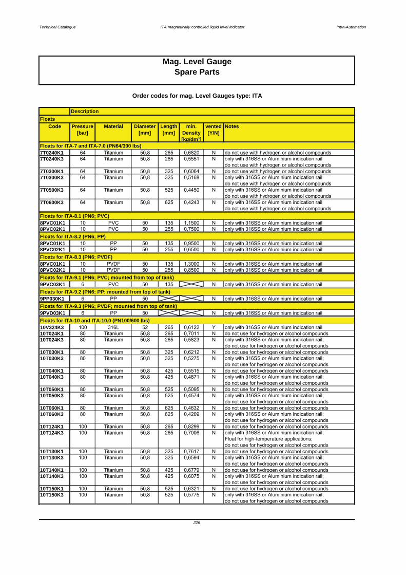
Technical Catalogue ITA magnetically controlled liquid level indicator Intra-Automation
Code Pressure[bar]
Material Diameter[mm]
Length[mm]
min. Density[kg/dm³]
vented[Y/N]
Notes
7T0240K1 64 Titanium 50,8 265 0,6820 N do not use with hydrogen or alcohol compounds7T0240K3 64 Titanium 50,8 265 0,5551 N only with 316SS or Aluminium indication rail
do not use with hydrogen or alcohol compounds7T0300K1 64 Titanium 50,8 325 0,6064 N do not use with hydrogen or alcohol compounds7T0300K3 64 Titanium 50,8 325 0,5168 N only with 316SS or Aluminium indication rail
do not use with hydrogen or alcohol compounds7T0500K3 64 Titanium 50,8 525 0,4450 N only with 316SS or Aluminium indication rail
do not use with hydrogen or alcohol compounds7T0600K3 64 Titanium 50,8 625 0,4243 N only with 316SS or Aluminium indication rail
do not use with hydrogen or alcohol compounds
8PVC01K1 10 PVC 50 135 1,1500 N only with 316SS or Aluminium indication rail8PVC02K1 10 PVC 50 255 0,7500 N only with 316SS or Aluminium indication rail
8PVC01K1 10 PP 50 135 0,9500 N only with 316SS or Aluminium indication rail8PVC02K1 10 PP 50 255 0,6500 N only with 316SS or Aluminium indication rail
8PVC01K1 10 PVDF 50 135 1,3000 N only with 316SS or Aluminium indication rail8PVC02K1 10 PVDF 50 255 0,8500 N only with 316SS or Aluminium indication rail
9PVC03K1 6 PVC 50 135 N only with 316SS or Aluminium indication rail
9PP030K1 6 PP 50 N only with 316SS or Aluminium indication rail
9PVD03K1 6 PP 50 N only with 316SS or Aluminium indication rail
10V324K3 100 316L 52 265 0,6122 Y only with 316SS or Aluminium indication rail10T024K1 80 Titanium 50,8 265 0,7011 N do not use for hydrogen or alcohol compounds10T024K3 80 Titanium 50,8 265 0,5823 N only with 316SS or Aluminium indication rail;
do not use for hydrogen or alcohol compounds10T030K1 80 Titanium 50,8 325 0,6212 N do not use for hydrogen or alcohol compounds10T030K3 80 Titanium 50,8 325 0,5275 N only with 316SS or Aluminium indication rail;
do not use for hydrogen or alcohol compounds10T040K1 80 Titanium 50,8 425 0,5515 N do not use for hydrogen or alcohol compounds10T040K3 80 Titanium 50,8 425 0,4871 N only with 316SS or Aluminium indication rail;
do not use for hydrogen or alcohol compounds10T050K1 80 Titanium 50,8 525 0,5095 N do not use for hydrogen or alcohol compounds10T050K3 80 Titanium 50,8 525 0,4574 N only with 316SS or Aluminium indication rail;
do not use for hydrogen or alcohol compounds10T060K1 80 Titanium 50,8 625 0,4632 N do not use for hydrogen or alcohol compounds10T060K3 80 Titanium 50,8 625 0,4209 N only with 316SS or Aluminium indication rail;
do not use for hydrogen or alcohol compounds10T124K1 100 Titanium 50,8 265 0,8299 N do not use for hydrogen or alcohol compounds10T124K3 100 Titanium 50,8 265 0,7006 N only with 316SS or Aluminium indication rail;
Float for high-temperature applications;do not use for hydrogen or alcohol compounds
10T130K1 100 Titanium 50,8 325 0,7617 N do not use for hydrogen or alcohol compounds10T130K3 100 Titanium 50,8 325 0,6594 N only with 316SS or Aluminium indication rail;
do not use for hydrogen or alcohol compounds10T140K1 100 Titanium 50,8 425 0,6779 N do not use for hydrogen or alcohol compounds10T140K3 100 Titanium 50,8 425 0,6075 N only with 316SS or Aluminium indication rail;
do not use for hydrogen or alcohol compounds10T150K1 100 Titanium 50,8 525 0,6321 N do not use for hydrogen or alcohol compounds10T150K3 100 Titanium 50,8 525 0,5775 N only with 316SS or Aluminium indication rail;
do not use for hydrogen or alcohol compounds
Floats for ITA-8.1 (PN6; PVC)
Floats for ITA-8.2 (PN6; PP)
Floats for ITA-9.2 (PN6; PP; mounted from top of tank)
Floats for ITA-9.3 (PN6; PVDF; mounted from top of tank)
Floats for ITA-10 and ITA-10.0 (PN100/600 lbs)
Mag. Level GaugeSpare Parts
226
Floats
Order codes for mag. Level Gauges type: ITA
Description
Floats for ITA-8.3 (PN6; PVDF)
Floats for ITA-9.1 (PN6; PVC; mounted from top of tank)
Floats for ITA-7 and ITA-7.0 (PN64/300 lbs)
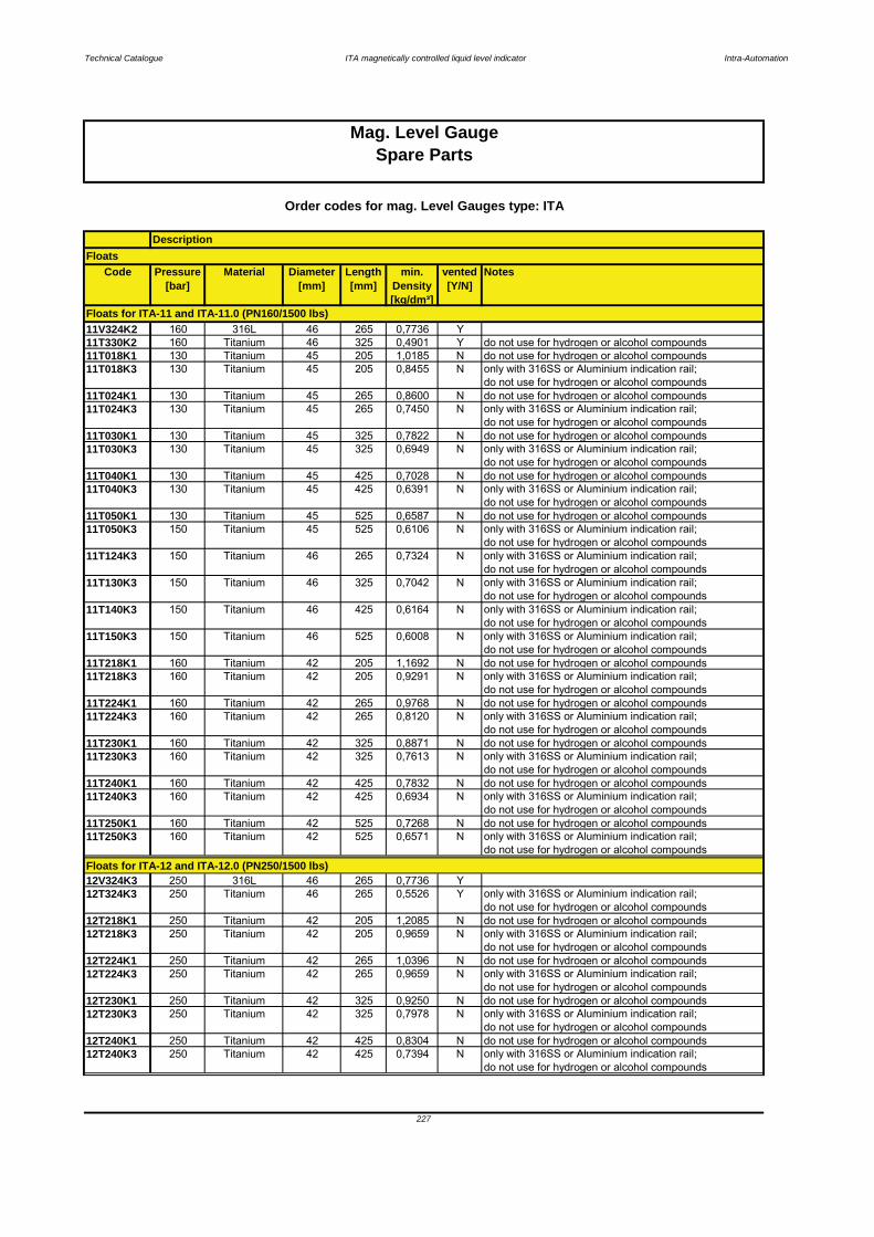
Technical Catalogue ITA magnetically controlled liquid level indicator Intra-Automation
Code Pressure[bar]
Material Diameter[mm]
Length[mm]
min. Density[kg/dm³]
vented[Y/N]
Notes
11V324K2 160 316L 46 265 0,7736 Y11T330K2 160 Titanium 46 325 0,4901 Y do not use for hydrogen or alcohol compounds11T018K1 130 Titanium 45 205 1,0185 N do not use for hydrogen or alcohol compounds11T018K3 130 Titanium 45 205 0,8455 N only with 316SS or Aluminium indication rail;
do not use for hydrogen or alcohol compounds11T024K1 130 Titanium 45 265 0,8600 N do not use for hydrogen or alcohol compounds11T024K3 130 Titanium 45 265 0,7450 N only with 316SS or Aluminium indication rail;
do not use for hydrogen or alcohol compounds11T030K1 130 Titanium 45 325 0,7822 N do not use for hydrogen or alcohol compounds11T030K3 130 Titanium 45 325 0,6949 N only with 316SS or Aluminium indication rail;
do not use for hydrogen or alcohol compounds11T040K1 130 Titanium 45 425 0,7028 N do not use for hydrogen or alcohol compounds11T040K3 130 Titanium 45 425 0,6391 N only with 316SS or Aluminium indication rail;
do not use for hydrogen or alcohol compounds11T050K1 130 Titanium 45 525 0,6587 N do not use for hydrogen or alcohol compounds11T050K3 150 Titanium 45 525 0,6106 N only with 316SS or Aluminium indication rail;
do not use for hydrogen or alcohol compounds11T124K3 150 Titanium 46 265 0,7324 N only with 316SS or Aluminium indication rail;
do not use for hydrogen or alcohol compounds11T130K3 150 Titanium 46 325 0,7042 N only with 316SS or Aluminium indication rail;
do not use for hydrogen or alcohol compounds11T140K3 150 Titanium 46 425 0,6164 N only with 316SS or Aluminium indication rail;
do not use for hydrogen or alcohol compounds11T150K3 150 Titanium 46 525 0,6008 N only with 316SS or Aluminium indication rail;
do not use for hydrogen or alcohol compounds11T218K1 160 Titanium 42 205 1,1692 N do not use for hydrogen or alcohol compounds11T218K3 160 Titanium 42 205 0,9291 N only with 316SS or Aluminium indication rail;
do not use for hydrogen or alcohol compounds11T224K1 160 Titanium 42 265 0,9768 N do not use for hydrogen or alcohol compounds11T224K3 160 Titanium 42 265 0,8120 N only with 316SS or Aluminium indication rail;
do not use for hydrogen or alcohol compounds11T230K1 160 Titanium 42 325 0,8871 N do not use for hydrogen or alcohol compounds11T230K3 160 Titanium 42 325 0,7613 N only with 316SS or Aluminium indication rail;
do not use for hydrogen or alcohol compounds11T240K1 160 Titanium 42 425 0,7832 N do not use for hydrogen or alcohol compounds11T240K3 160 Titanium 42 425 0,6934 N only with 316SS or Aluminium indication rail;
do not use for hydrogen or alcohol compounds11T250K1 160 Titanium 42 525 0,7268 N do not use for hydrogen or alcohol compounds11T250K3 160 Titanium 42 525 0,6571 N only with 316SS or Aluminium indication rail;
do not use for hydrogen or alcohol compounds
12V324K3 250 316L 46 265 0,7736 Y12T324K3 250 Titanium 46 265 0,5526 Y only with 316SS or Aluminium indication rail;
do not use for hydrogen or alcohol compounds12T218K1 250 Titanium 42 205 1,2085 N do not use for hydrogen or alcohol compounds12T218K3 250 Titanium 42 205 0,9659 N only with 316SS or Aluminium indication rail;
do not use for hydrogen or alcohol compounds12T224K1 250 Titanium 42 265 1,0396 N do not use for hydrogen or alcohol compounds12T224K3 250 Titanium 42 265 0,9659 N only with 316SS or Aluminium indication rail;
do not use for hydrogen or alcohol compounds12T230K1 250 Titanium 42 325 0,9250 N do not use for hydrogen or alcohol compounds12T230K3 250 Titanium 42 325 0,7978 N only with 316SS or Aluminium indication rail;
do not use for hydrogen or alcohol compounds12T240K1 250 Titanium 42 425 0,8304 N do not use for hydrogen or alcohol compounds12T240K3 250 Titanium 42 425 0,7394 N only with 316SS or Aluminium indication rail;
do not use for hydrogen or alcohol compounds
FloatsDescription
Mag. Level Gauge
Floats for ITA-12 and ITA-12.0 (PN250/1500 lbs)
Floats for ITA-11 and ITA-11.0 (PN160/1500 lbs)
Order codes for mag. Level Gauges type: ITA
227
Spare Parts
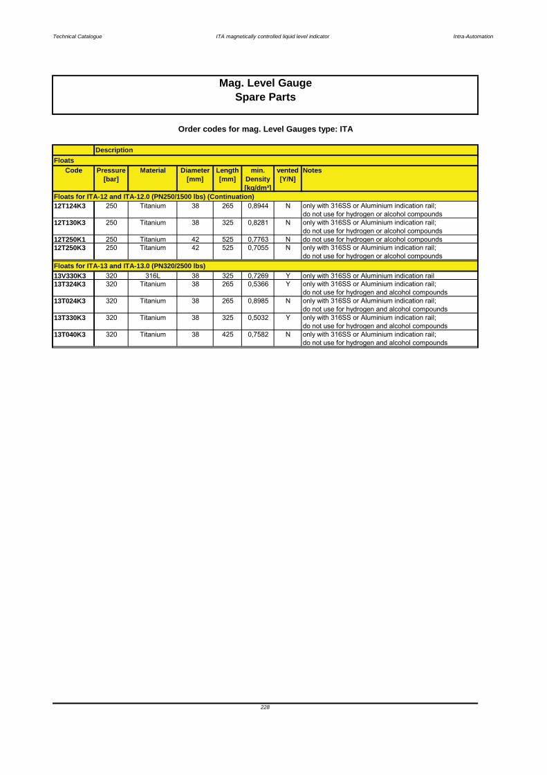
Technical Catalogue ITA magnetically controlled liquid level indicator Intra-Automation
Code Pressure[bar]
Material Diameter[mm]
Length[mm]
min. Density[kg/dm³]
vented[Y/N]
Notes
12T124K3 250 Titanium 38 265 0,8944 N only with 316SS or Aluminium indication rail;do not use for hydrogen or alcohol compounds
12T130K3 250 Titanium 38 325 0,8281 N only with 316SS or Aluminium indication rail;do not use for hydrogen or alcohol compounds
12T250K1 250 Titanium 42 525 0,7763 N do not use for hydrogen or alcohol compounds12T250K3 250 Titanium 42 525 0,7055 N only with 316SS or Aluminium indication rail;
do not use for hydrogen or alcohol compounds
13V330K3 320 316L 38 325 0,7269 Y only with 316SS or Aluminium indication rail13T324K3 320 Titanium 38 265 0,5366 Y only with 316SS or Aluminium indication rail;
do not use for hydrogen and alcohol compounds13T024K3 320 Titanium 38 265 0,8985 N only with 316SS or Aluminium indication rail;
do not use for hydrogen and alcohol compounds13T330K3 320 Titanium 38 325 0,5032 Y only with 316SS or Aluminium indication rail;
do not use for hydrogen and alcohol compounds13T040K3 320 Titanium 38 425 0,7582 N only with 316SS or Aluminium indication rail;
do not use for hydrogen and alcohol compounds
Floats
Order codes for mag. Level Gauges type: ITA
Description
Mag. Level GaugeSpare Parts
228
Floats for ITA-12 and ITA-12.0 (PN250/1500 lbs) (Continuation)
Floats for ITA-13 and ITA-13.0 (PN320/2500 lbs)
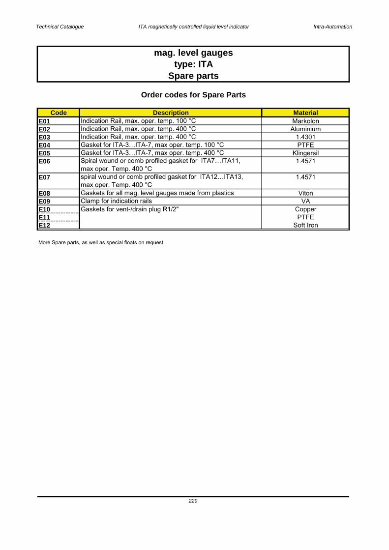
Technical Catalogue ITA magnetically controlled liquid level indicator Intra-Automation
Code DescriptionE01 Indication Rail, max. oper. temp. 100 °C E02 Indication Rail, max. oper. temp. 400 °C E03 Indication Rail, max. oper. temp. 400 °C E04 Gasket for ITA-3…ITA-7, max oper. temp. 100 °CE05 Gasket for ITA-3…ITA-7, max oper. temp. 400 °CE06 Spiral wound or comb profiled gasket for ITA7…ITA11,
max oper. Temp. 400 °CE07 spiral wound or comb profiled gasket for ITA12…ITA13,
max oper. Temp. 400 °CE08 Gaskets for all mag. level gauges made from plasticsE09 Clamp for indication railsE10E11E12
More Spare parts, as well as special floats on request.
Soft Iron
mag. level gaugestype: ITA
Spare parts
Material
1.4571
1.4571
VitonVA
229
Gaskets for vent-/drain plug R1/2"
Order codes for Spare Parts
MarkolonAluminium
1.4301PTFE
Klingersil
CopperPTFE
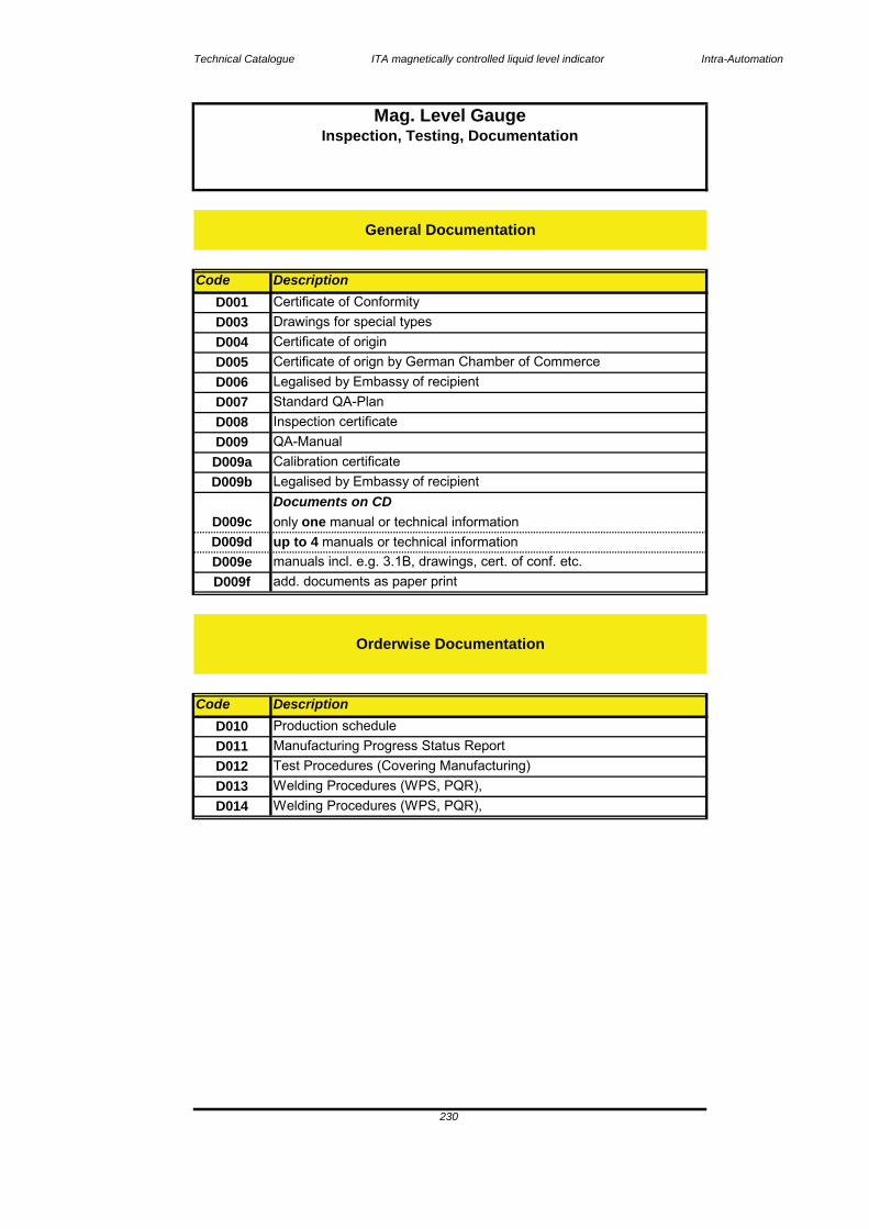
Technical Catalogue ITA magnetically controlled liquid level indicator Intra-Automation
CodeD001D003D004D005D006D007D008D009D009aD009b
D009cD009dD009eD009f
CodeD010D011D012D013D014
Test Procedures (Covering Manufacturing)Welding Procedures (WPS, PQR), Welding Procedures (WPS, PQR), S i l i l
Certificate of Conformity
Legalised by Embassy of recipient
Drawings for special typesCertificate of originCertificate of orign by German Chamber of Commerce
Production scheduleManufacturing Progress Status Report
manuals incl. e.g. 3.1B, drawings, cert. of conf. etc.add. documents as paper print
Calibration certificate
Description
Description
Legalised by Embassy of recipientStandard QA-PlanInspection certificateQA-Manual
Documents on CD
up to 4 manuals or technical informationonly one manual or technical information
Mag. Level GaugeInspection, Testing, Documentation
Orderwise Documentation
General Documentation
230
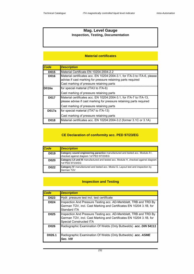
Technical Catalogue ITA magnetically controlled liquid level indicator Intra-Automation
CodeD015
Code
CodeD023
D016a
Material Certificate EN 10204:2004-2.2
Cast marking of pressure retaining parts
Cast marking of pressure retaining partsMaterial certificates acc. EN 10204:2004-3.1, for ITA-7 to ITA-13, please advise if cast marking for pressure retaining parts requiredCast marking of pressure retaining parts
Description
Cast marking of pressure retaining parts
Material certificates acc. EN 10204:2004-3.1, for ITA-3 to ITA-6, please advise if cast marking for pressure retaining parts required
Mag. Level Gauge
for special material (ITA3 to ITA-6)
D017a
D026
D025 Inspection And Pressure Testing acc. AD-Merkblatt, TRB and TRD By German TÜV, incl. Cast Marking and Certificates EN 10204 3.1B, for Special Constructed ITARadiographic Examination Of Welds (Only Buttwelds) acc. DIN 54111
D026.1 Radiographic Examination Of Welds (Only Buttwelds) acc. ASME Sec. VIII
Inspection, Testing, Documentation
Description
Description
Hydr. pressure test incl. test certificate
Inspection and Testing
D022
D020
Category IV manufactured and tested acc. Modul G. Layout test and inspection by German TÜV
CE Declaration of conformity acc. PED 97/23/EG
for special material (ITA7 to ITA-13)
D018
D017
Material certificates
D016
Material certificates acc. EN 10204:2004-3.2 (former 3.1C or 3.1A)
231
D024 Inspection And Pressure Testing acc. AD-Merkblatt, TRB and TRD By German TÜV, incl. Cast Marking and Certificates EN 10204 3.1B, for Standard ITA
D019 Category sound engineering paractice manufactured and tested acc. Module A1, checked against diagram 1of PED 97/23/EGCategory I,II und III manufactured and tested acc. Module H, checked against diagram 1of PED 97/23/EG

Technical Catalogue ITA magnetically controlled liquid level indicator Intra-Automation
Code
D028D029
Code DescriptionD032D033
General notes:
Standard wiring plans and data sheetsATEX-certificates
The standard documentation mentioned in our quotations and order acknowledgements consists of: 1 off installation & operation manual (hard copy)
D031
Certificates for electronic equipment
Percentage of ferrite in welding
D032 Endoscopy (Weldings inside) + Photo/Video
D030 PMI-Check
D027.1 Dyepenetrant Examination Of Welds acc.ASME Sec. VIII
Härteprüfung nach NACE MR01-75, incl. NACE-Weight Certificate (for all units of an order)
D027 Dyepenetrant Examination Of Welds acc. EN473:2000 and PED
Inspection and Testing (Continuation)
Description
232
Mag. Level GaugeInspection, Testing, Documentation

Technical Catalogue ITA magnetically controlled liquid level indicator Intra-Automation
Technical Information / ITA-T1S special features
Simple and rugged design
therefore suitable for small vessels.indicating length up to 3000 mm (118")resistant to pressures of 40 bar (580 psi g) andtemperatures of 300 °F (266 °F)housing: casst aluminium or stainless steel inIP65, equivalent to NEMA 4 and NEMA 4Xenclosurewide variety of material combinationsvarious plastic coatings availabel for all wetted parts4…20 mA or Hart protocol 4…20 mA output via thesignal amplifier
Introduction
Operation Fig 1: ITA-T1S with Eexd housingand tank mounting flange
Fig 2 diagammatic view of reed
Monitoring switches
Fig 3 Digiflow 520
5. Special Constructions
5.1 ITA-T1S Continuous level sensing element
Intra-Automation does not limit you with the standard designs catalogued here. Our experienced engineering staff, with extensive research and development capabilities, will customize liquid level indicators to meet your specific requirements. Modifications regarding the variety of mountings, exotic materials and float configurations provide compatibility for most liquid media, various tank temperatures and pressures, as well as liquids with a broad range of specific gravities.
The ITA-T1S Liquid Level Transmitters, vertically mounted in the tank and cable connected (3-wire) to a remote receiver, operates on the float principle.
233
A float guided on a non-magnetic tube follows the level of the liquid surface, thereby actuating the reed switches located inside the tube by means of a built-in magnet system. The reed switches shunt over parts of a resistor string.The magnet system operates the reed switches according to the position of the float and thus causes the resistance of the resistor string to change as a function for liquid level.A current 4...20 mA is then obtained as an output signal together with the INT5333; INT5333ATEX; TMT182 signal conditioner. The float travel distance can be limited by stops fitted to the guide tube.
Combined with DigiFlow 520 these transmitters form a complete liquid level monitoring system. Used as a separate system with a process control system, Intra transmitters can interface with programmable controllers and other industrial microprocessors.
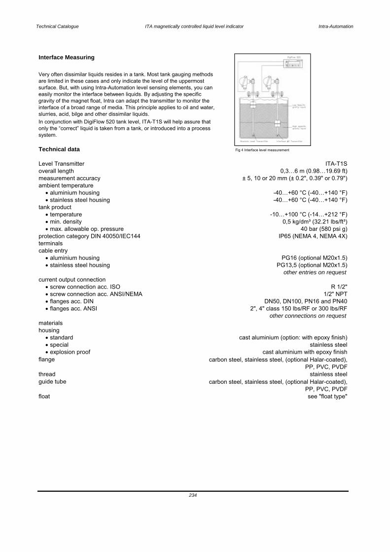
Technical Catalogue ITA magnetically controlled liquid level indicator Intra-Automation
Interface Measuring
Technical data Fig 4 Interface level measurement
Very often dissimilar liquids resides in a tank. Most tank gauging methods are limited in these cases and only indicate the level of the uppermost surface. But, with using Intra-Automation level sensing elements, you can easily monitor the interface between liquids. By adjusting the specific gravity of the magnet float, Intra can adapt the transmitter to monitor the interface of a broad range of media. This principle applies to oil and water, slurries, acid, bilge and other dissimilar liquids.In conjunction with DigiFlow 520 tank level, ITA-T1S will help assure that only the “correct” liquid is taken from a tank, or introduced into a process system.
Level Transmitter ITA-T1S
housing
flange
screw connection acc. ISO screw connection acc. ANSI/NEMA flanges acc. DIN flanges acc. ANSI
standard special explosion proof
min. density max. allowable op. pressure
aluminium housing
materials
protection category DIN 40050/IEC144terminalscable entry
current output connection
stainless steel housing
aluminium housing stainless steel housing
temperature
overall lengthmeasurement accuracyambient temperature
tank product-40…+60 °C (-40…+140 °F)
-10…+100 °C (-14…+212 °F)0,5 kg/dm³ (32.21 lbs/ft³)
0,3…6 m (0.98…19.69 ft) ± 5, 10 or 20 mm (± 0.2", 0.39" or 0.79")
-40…+60 °C (-40…+140 °F)
PG16 (optional M20x1.5)PG13,5 (optional M20x1.5)
R 1/2"
other entries on request
40 bar (580 psi g)IP65 (NEMA 4, NEMA 4X)
cast aluminium (option: with epoxy finish)stainless steel
cast aluminium with epoxy finish
1/2" NPTDN50, DN100, PN16 and PN40
2", 4" class 150 lbs/RF or 300 lbs/RFother connections on request
234
carbon steel, stainless steel, (optional Halar-coated),PP, PVC, PVDF
stainless steelcarbon steel, stainless steel, (optional Halar-coated),
PP, PVC, PVDF see "float type"
threadguide tube
float

Technical Catalogue ITA magnetically controlled liquid level indicator Intra-Automation
Float type
type 1) shape dimensions inmm (inches)
material min. densitykg/dm³(lbs/ft³
max. op.Pressure inbar (psi g)
@ 20 °C (38 °F)
max. liquidtemperature
in °C (°F)
A spherical 52(2.05)
1.4571(316Ti)
0,7(43.70)
40(580)
-40…+100(-40…+266)
B spherical 80(3.15)
3.7035(Titanium)
0,6(37.46)
17(247)
-40…+100(-40…+266)
C cylindrical 80x35(3.15x1.38)
1.4571(316Ti)
0,5(31.21)
13(189)
-40…+100(-40…+266)
D cylindrical 44x52 1.4571(316Ti)
0,8(49.94)
25(362)
-40…+100(-40…+266)
E cylindrical 32x34 Buna N 0,55 10(150)
0…+82(-18…+180)
F cylindrical 32x34 Intox 0,5 100(1450)
-40…+100(-40…+266)
1) other types on request
Float type A Float type B Float type C
Float type D Float type E Float type F
Transmitter
Type Outputin mA
Supplyvoltagein VDC
Currentin mA
Operatingtemperature
in °C (°F)
Min./max. resistance
in Ohm
Approval
INT5333 4…20 8…28 4…20 -20…+85(-4…+185)
506000
non
TMT182 4…20 10…30 4…20 -40…+85 0…4000…2000
EEx ia CFM IS
CSA ISTMT184 Profibus 10…35 Profibus -40…+85 10…400
10…2000EEx ia CII
ATEXFM
CSA
235
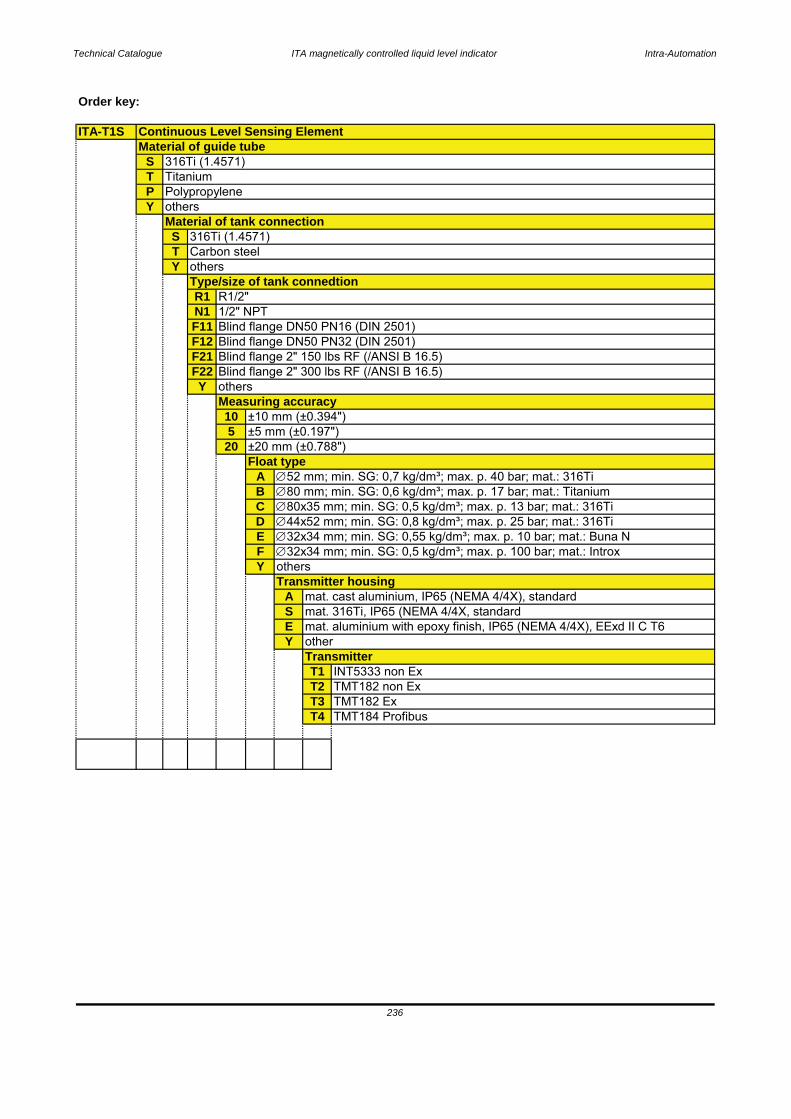
Technical Catalogue ITA magnetically controlled liquid level indicator Intra-Automation
Order key:
ITA-T1S
STPY
STY
R1N1F11F12F21F22Y
105
20
ABCDEFY
ASEY
T1 INT5333 non ExT2 TMT182 non ExT3 TMT182 ExT4 TMT184 Profibus
Transmitter housingmat. cast aluminium, IP65 (NEMA 4/4X), standard
236
mat. 316Ti, IP65 (NEMA 4/4X, standardmat. aluminium with epoxy finish, IP65 (NEMA 4/4X), EExd II C T6otherTransmitter
80 mm; min. SG: 0,6 kg/dm³; max. p. 17 bar; mat.: Titanium80x35 mm; min. SG: 0,5 kg/dm³; max. p. 13 bar; mat.: 316Ti44x52 mm; min. SG: 0,8 kg/dm³; max. p. 25 bar; mat.: 316Ti32x34 mm; min. SG: 0,55 kg/dm³; max. p. 10 bar; mat.: Buna N32x34 mm; min. SG: 0,5 kg/dm³; max. p. 100 bar; mat.: Introx
others
Measuring accuracy±10 mm (±0.394")±5 mm (±0.197")±20 mm (±0.788")Float type
52 mm; min. SG: 0,7 kg/dm³; max. p. 40 bar; mat.: 316Ti
1/2" NPTBlind flange DN50 PN16 (DIN 2501)Blind flange DN50 PN32 (DIN 2501)Blind flange 2" 150 lbs RF (/ANSI B 16.5)Blind flange 2" 300 lbs RF (/ANSI B 16.5)others
Material of tank connection316Ti (1.4571)Carbon steelothersType/size of tank connedtion
R1/2"
Continuous Level Sensing ElementMaterial of guide tube
316Ti (1.4571)TitaniumPolypropyleneothers
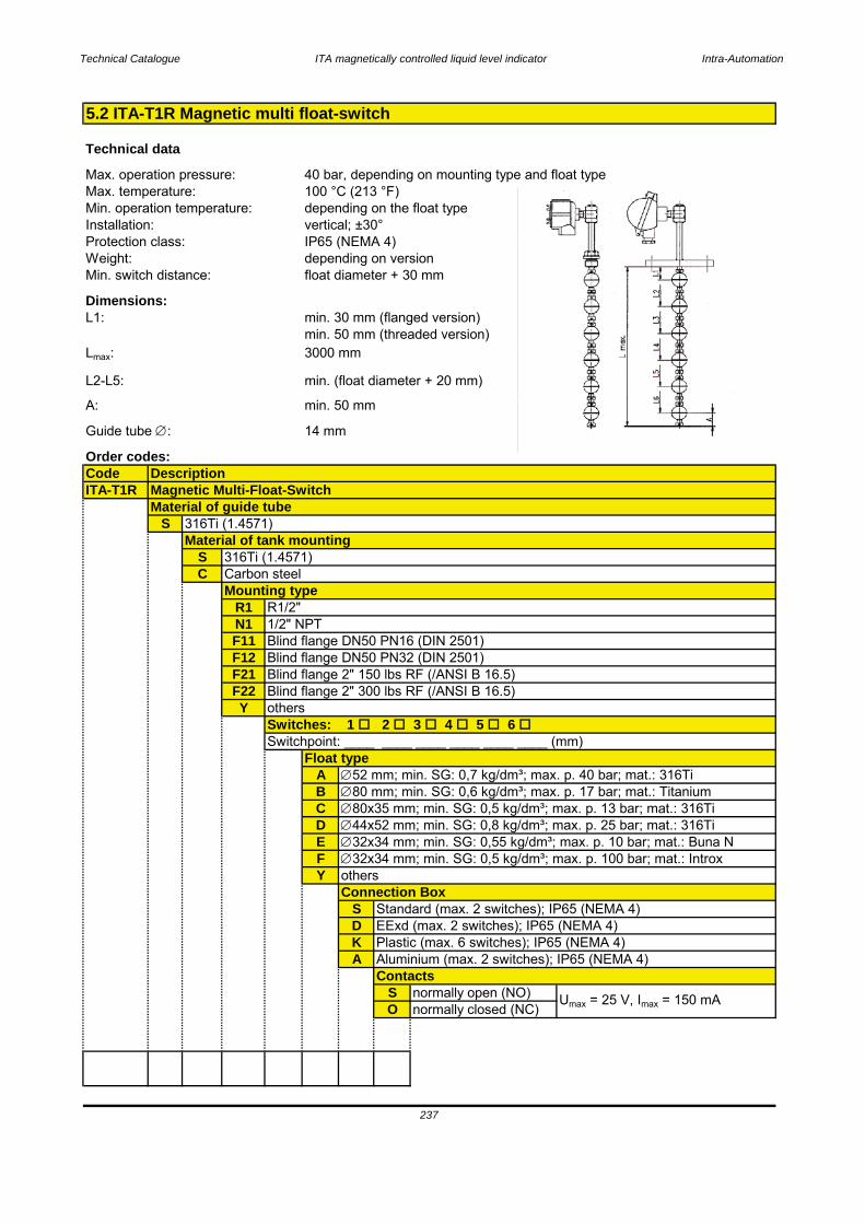
Technical Catalogue ITA magnetically controlled liquid level indicator Intra-Automation
Technical data
Dimensions:
Order codes:CodeITA-T1R
S
SC
R1N1F11F12F21F22Y
ABCDEFY
SDKA
S normally open (NO)O normally closed (NC)
237
Guide tube :
min. 30 mm (flanged version)min. 50 mm (threaded version)3000 mm
min. (float diameter + 20 mm)
min. 50 mm
14 mm
L1:
Lmax:
EExd (max. 2 switches); IP65 (NEMA 4)Plastic (max. 6 switches); IP65 (NEMA 4)Aluminium (max. 2 switches); IP65 (NEMA 4)
Umax = 25 V, Imax = 150 mA
Contacts
40 bar, depending on mounting type and float type100 °C (213 °F)depending on the float typevertical; ±30°
Float type
Standard (max. 2 switches); IP65 (NEMA 4)Connection Box
52 mm; min. SG: 0,7 kg/dm³; max. p. 40 bar; mat.: 316Ti80 mm; min. SG: 0,6 kg/dm³; max. p. 17 bar; mat.: Titanium80x35 mm; min. SG: 0,5 kg/dm³; max. p. 13 bar; mat.: 316Ti44x52 mm; min. SG: 0,8 kg/dm³; max. p. 25 bar; mat.: 316Ti32x34 mm; min. SG: 0,55 kg/dm³; max. p. 10 bar; mat.: Buna N32x34 mm; min. SG: 0,5 kg/dm³; max. p. 100 bar; mat.: Introx
others
Blind flange DN50 PN32 (DIN 2501)Blind flange 2" 150 lbs RF (/ANSI B 16.5)Blind flange 2" 300 lbs RF (/ANSI B 16.5)othersSwitches: 1 2 3 4 5 6 Switchpoint: ____ ____ ____ ____ ____ ____ (mm)
5.2 ITA-T1R Magnetic multi float-switch
DescriptionMagnetic Multi-Float-SwitchMaterial of guide tube
Max. operation pressure:Max. temperature:Min. operation temperature:Installation:Protection class:Weight:
316Ti (1.4571)Material of tank mounting
L2-L5:
A:
Min. switch distance:
IP65 (NEMA 4)depending on versionfloat diameter + 30 mm
1/2" NPTBlind flange DN50 PN16 (DIN 2501)
316Ti (1.4571)Carbon steelMounting type
R1/2"
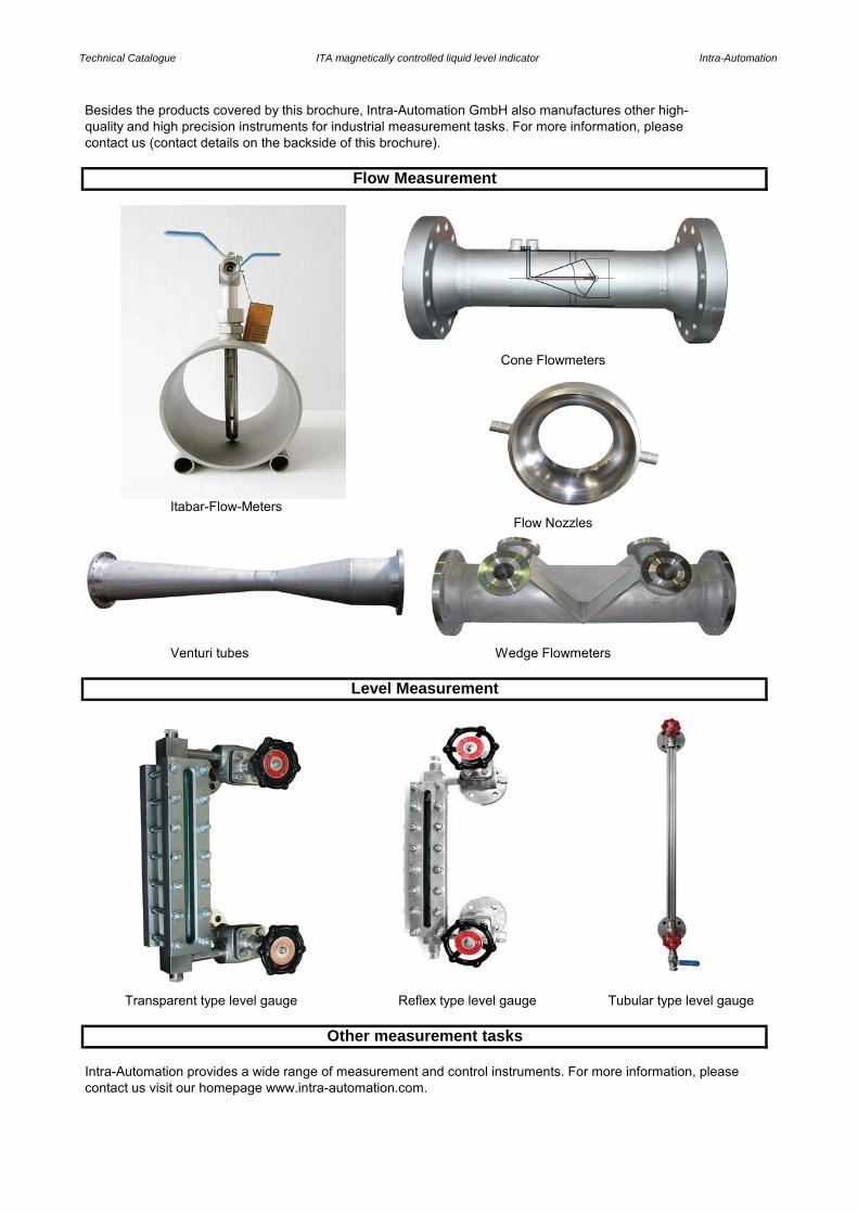
Technical Catalogue ITA magnetically controlled liquid level indicator Intra-Automation
Besides the products covered by this brochure, Intra-Automation GmbH also manufactures other high-quality and high precision instruments for industrial measurement tasks. For more information, pleasecontact us (contact details on the backside of this brochure).
Itabar-Flow-Meters
Venturi tubes
Intra-Automation provides a wide range of measurement and control instruments. For more information, pleasecontact us visit our homepage www.intra-automation.com.
Flow Measurement
Cone Flowmeters
Flow Nozzles
Wedge Flowmeters
Other measurement tasks
Level Measurement
Transparent type level gauge Reflex type level gauge Tubular type level gauge
Technical Catalogue ITA magnetically controlled liquid level indicator Intra-Automation
Headquarters: Subsidiary in the Netherlands:(Germany, world-wide sales) (Sales in the Benelux-States)INTRA-AUTOMATION GmbH BV INTRA-AUTOMATION HTPOtto-Hahn-Strasse 20 Keulsveld 1741515 Grevenbroich 4705 RS RoosendaalGERMANY THE NETHERLANDS
+49-(0)2181-75665-0 +31-(0)165-322201 +49-(0)2181-64492 +31-(0)165-322970 [email protected] [email protected]
Please also visit our homepage www.intra-automation.com.


![PVEA/H/S Electrohydraulic Actuator Product Electrical ...pvglobal.com.sg/img/cms/technical_information/11022641...s 1.0[0.039] LVDT Signal Input Signal The following data is for a](https://img.pdfslide.us/doc/110x75/610140edc8c65523fd307450/pveahs-electrohydraulic-actuator-product-electrical-s-100039-lvdt.jpg)