Embed Size (px)
Citation preview
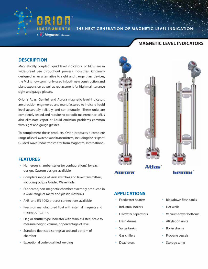
MAGNETIC LEVEL INDICATORS
DESCRIPTIONMagnetically coupled liquid level indicators, or MLIs, are in
widespread use throughout process industries. Originally
designed as an alternative to sight and gauge glass devices,
the MLI is now commonly used in both new construction and
plant expansion as well as replacement for high maintenance
sight and gauge glasses.
Orion’s Atlas, Gemini, and Aurora magnetic level indicators
are precision engineered and manufactured to indicate liquid
level accurately, reliably, and continuously. These units are
completely sealed and require no periodic maintenance. MLIs
also eliminate vapor or liquid emission problems common
with sight and gauge glasses.
To complement these products, Orion produces a complete
range of level switches and transmitters, including the Eclipse®
Guided Wave Radar transmitter from Magnetrol International.
• Numerous chamber styles (or configurations) for each
design. Custom designs available.
• Complete range of level switches and level transmitters,
including Eclipse Guided Wave Radar
• Fabricated, non-magnetic chamber assembly produced in
a wide range of metal and plastic materials
• ANSI and EN 1092 process connections available
• Precision manufactured float with internal magnets and
magnetic flux ring
• Flag or shuttle type indicator with stainless steel scale to
measure height, volume, or percentage of level
• Standard float stop springs at top and bottom of
chamber
• Exceptional code qualified welding
FEATURES
• Feedwater heaters
• Industrial boilers
• Oil/water separators
• Flash drums
• Surge tanks
• Gas chillers
• Deaerators
• Blowdown flash tanks
• Hot wells
• Vacuum tower bottoms
• Alkylation units
• Boiler drums
• Propane vessels
• Storage tanks
APPLICATIONS
������������������� ������������������������
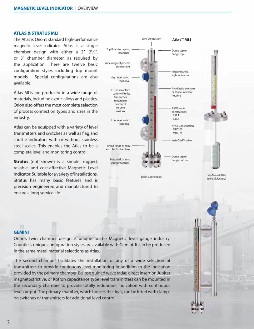
The Atlas is Orion’s standard high-performance
magnetic level indicator. Atlas is a single
chamber design with either a 2", 21⁄2",
or 3" chamber diameter, as required by
the application. There are twelve basic
configuration styles including top mount
models. Special configurations are also
available.
Atlas MLIs are produced in a wide range of
materials, including exotic alloys and plastics.
Orion also offers the most complete selection
of process connection types and sizes in the
industry.
Atlas can be equipped with a variety of level
transmitters and switches as well as flag and
shuttle indicators with or without stainless
steel scales. This enables the Atlas to be a
complete level and monitoring control.
Stratus (not shown) is a simple, rugged,
reliable, and cost-effective Magnetic Level
Indicator. Suitable for a variety of installations,
Stratus has many basic features and is
precision engineered and manufactured to
ensure a long service life.
GEMINIOrion’s twin chamber design is unique to the Magnetic level gauge industry.
Countless unique configuration styles are available with Gemini. It can be produced
in the same metal material selections as Atlas.
The second chamber facilitates the installation of any of a wide selection of
transmitters to provide continuous level monitoring in addition to the indication
provided by the primary chamber. Eclipse guided wave radar, direct insertion Jupiter
magnetostrictive, or Kotron capacitance type level transmitters can be mounted in
the secondary chamber to provide totally redundant indication with continuous
level output. The primary chamber, which houses the float, can be fitted with clamp-
on switches or transmitters for additional level control.
ATLAS & STRATUS MLIVent Connection
Broad range of alloy and plastic chambers
Wide range of process connections
Dome cap or flange top
Flag or shuttle style indicators
316 SS scale for a variety of units:feet/inchesmeters/cmpercent %
volumecustom
Insta-Seal™ valve
Dome cap or flange bottom
Top float stop spring (standard)
High level switch(optional)
Drain Connection
Low level switch(optional)
Bottom float stop spring (standard)
ASME code construction: B31.1 B31.3
NACE Construction: MR0103 MR0175
Anodized aluminum or 316 SS indicator housing
Top Mount Atlas(consult factory)
MAGNETIC LEVEL INDICATOR | OVERVIEW
2
Atlas™ MLI

Eclipse® GWRLevel Transmitter
Float
GWR Probe
Baffle PlateVisual
Indicator
Top View
• Wide range of alloy materials
• Eclipse available with HART®, FOUNDATION fieldbus™, or PROFIBUS™ communication
• Large selection of process connection options
• Eight probe designs cover a broad range of applications
• Eclipse transmitter available in 316 stainless steel or epoxy-coated aluminum
• ASME B31.1, B31.3, or NACE; 150# to 2500# ANSI (PN 16 to PN 320)
• Top and bottom float stop springs
AURORA® FEATURES
DESCRIPTION
Gas BypassZone
OVERVIEW | AURORA® MAGNETIC LEVEL INDICATOR
See Brochure ORI-101 for more information
Level Transmitter
•
•
•
•
•
•
•
A
DAurora’s patented design is the next generation of magnetic level indicators. It is state of the
art and reflects Orion’s innovation and commitment to magnetic level indicators.
Aurora is a totally redundant monitoring and control system. Liquid levels are tracked with
great accuracy using two different technologies. An Eclipse® guided wave radar probe is
housed along with the MLI float in a 3" or 4" diameter chamber. While the indicator relies
upon the float and its internal magnets to activate the flags or shuttle, the Eclipse measures
the liquid level directly. Two completely separate technologies in a single external chamber
equal redundancy unlike any other MLI. The use of a special baffle within the chamber
ensures that the float and Eclipse® probe work seamlessly and without interference.
There are ten basic configuration styles and over fifteen material selections for Aurora. For
the first time ever, the ability to accurately and reliably measure ultra low dielectric media,
high pressure/high temperature process conditions, and media with shifting and changing
dielectric values can be accomplished with Aurora.
3
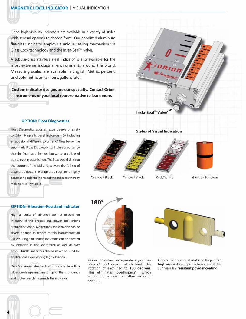
Orange / Black Red / WhiteYellow / Black Shuttle / Follower
Styles of Visual Indication
OPTION: Float Diagnostics
OPTION: Vibration-Resistant Indicator
Orion high-visibility indicators are available in a variety of styles
with several options to choose from. Our anodized aluminum
flat-glass indicator employs a unique sealing mechanism via
Glass-Lock technology and the Insta-Seal™ valve.
A tubular-glass stainless steel indicator is also available for the
most extreme industrial environments around the world.
Measuring scales are available in English, Metric, percent,
and volumetric units (liters, gallons, etc).
Custom indicator designs are our specialty. Contact Orion
Instruments or your local representative to learn more.
Float Diagnostics adds an extra degree of safety
to Orion Magnetic Level Indicators. By including
an additional, different color set of flags below the
zero mark, Float Diagnostics will alert a passer-by
that the float has either lost buoyancy or collapsed
due to over-pressurization. The float would sink into
the bottom of the MLI and activate the full set of
diagnostic flags. The diagnostic flags are a highly
contrasting color to the rest of the indicator, thereby
making it easily visible.
High amounts of vibration are not uncommon
in many of the process and power applications
around the world. Many times, the vibration can be
severe enough to render certain instrumentation
useless. Flag and Shuttle indicators can be affected
by vibration in the short-term, as well as over
time. Shuttle indicators should never be used for
applications experiencing high vibration.
Orion’s stainless steel indicator is available with a
vibration-dampening inert liquid that surrounds
and protects each flag inside the indicator.
Insta-SealTM Valve
Orion’s highly robust metallic flags offer high visibility and protection against the sun via a UV resistant powder coating.
Orion indicators incorporate a ������������ �� ���� design which limits the rotation of each flag to 180 degrees. This eliminates "overflipping" which is commonly seen on other indicator designs.
180°
MAGNETIC LEVEL INDICATOR | VISUAL INDICATION
4
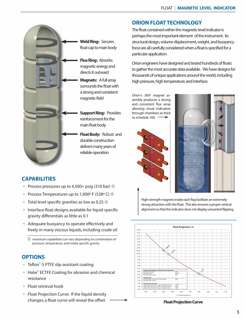
ORION FLOAT TECHNOLOGY
CAPABILITIES
Weld Ring: Secures
float cap to main body
Flux Ring: Absorbs
magnetic energy and
directs it outward
Magnets: A full array
surrounds the float with
a strong and consistent
magnetic field
OPTIONS
• Process pressures up to 4,500+ psig (310 bar) �
• Process Temperatures up to 1,000º F (538º C) �
• Total level specific gravities as low as 0.25 �
• Interface float designs available for liquid specific
gravity differentials as little as 0.1
• Adequate buoyancy to operate effectively and
freely in many viscous liquids, including crude oil
Support Ring: Provides
reinforcement for the
main float body
Float Body: Robust and
durable construction
delivers many years of
reliable operation
• Teflon®-S PTFE slip-assistant coating
• Halar® ECTFE Coating for abrasion and chemical
resistance
• Float retrieval hook
• Float Projection Curve: If the liquid density
changes, a float curve will reveal the offset
High-strength magnets inside each flag facilitate an extremely strong attraction with the float. This also ensures a proper vertical alignment so that the indicator does not display unwanted flipping.
Float Projection Curve
The float contained within the magnetic level indicator is
perhaps the most important element of the instrument. Its
structural design, volume displacement, weight, and buoyancy
force are all carefully considered when a float is specified for a
particular application.
Orion engineers have designed and tested hundreds of floats
to gather the most accurate data available. We have designs for
thousands of unique applications around the world, including
high pressure, high temperature, and interface.
Orion’s 360º magnet as-sembly produces a strong and consistent flux array allowing visual indication through chambers as thick as schedule 160.
FLOAT | MAGNETIC LEVEL INDICATOR
5
maximum capabilities can vary depending on combination of pressure, temperature, and media specific gravity
�
Design Atlas, Aurora, Stratus – single chamber
Gemini – dual chamber
Materials of construction – MLI Metal alloys 316/316L or 304/304L stainless steel,
321 stainless steel, 347 stainless steel,
Titanium, Monel, Hastelloy B,
Hastelloy C-276, Inconel 625, Inconel 825,
Alloy 20, Electropolished 316 stainless steel,
904L stainless steel and other non-magnetic alloys
Plastics / Composites Fiberglass, PVC, CPVC, Kynar, polypropylene
Materials of construction – Float varies per application - stainless steel and titanium are standard (exotic alloys available)
Construction options Conformance to ASME B31.1, ASME B31.3, and NACE available
Certified material test reports (CMTR) Available upon request
Pressure class ratings ANSI 150#, 300#, 600#, 900#, 1500#, 2500#
DIN PN16, PN25, PN40, PN63, PN100, PN160, PN250, PN320
Process connection sizes 1⁄2" to 8"
DN 20 to DN 150
Process connection types MNPT, FNPT, Weldolet®, Sockolet®, threaded nipple, buttweld nipple, plain-end nipple,
slip-on flanges, weldneck flanges, lap joint flanges,
TriClamp® fitting, Van Stone flanges
Measuring range 12 to 600 in (30 to 1524 cm)
Temperature range -320° to +1000° F (-196° to +538° C)
Pressure range Full vacuum to 4500 psig (310 bar)
Specific gravity range As low as 0.25 S.G. (consult factory for lower specific gravities)
Indicators Magnetically actuated flag assembly in contrasting orange/black, yellow/black,
red/white colors, or high visibility shuttle follower (custom colors available)
Flag assembly seal Inert gas filled and sealed with Insta-Seal™ valve
Visual indication Easily visible from 100 feet (30 meters)
Scale options Etched stainless steel with either height, volume, or percentage units (custom markings avail)
Switch options Model OES electric cam operated snap action (refer to Orion bulletin: OES-100)
Model ORS electric reed type (refer to Orion bulletin: ORS-300)
Pneumatic switch available (consult factory)
Transmitter options Model 705 Eclipse guided wave radar (refer to Magnetrol bulletin: 57-101 & 57-102)
Model 2xx Jupiter Magnetostrictive (refer to Orion bulletin: ORI-148)
Model OCT analog reed chain (refer to Orion bulletin: OCT-400)
High temperature options Electric or steam tracing with or without special high temperature insulation
Low temperature options Cryogenic insulation with special polymeric frost extension
MAGNETIC LEVEL INDICATOR | SPECIFICATIONS
6
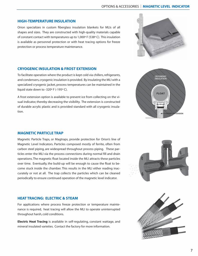
HIGH-TEMPERATURE INSULATION
Orion specializes in custom fiberglass insulation blankets for MLIs of all
shapes and sizes. They are constructed with high-quality materials capable
of constant contact with temperatures up to 1,000º F (538º C). This insulation
is available as personnel protection or with heat tracing options for freeze
protection or process temperature maintenance.
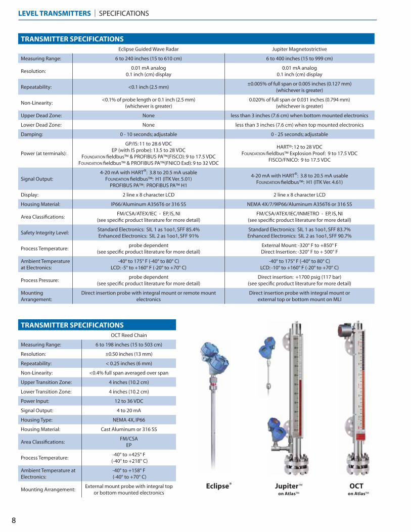
CRYOGENIC INSULATION & FROST EXTENSION
To facilitate operation where the product is kept cold via chillers, refrigerants,
and condensers, cryogenic insulation is provided. By insulating the MLI with a
specialized cryogenic jacket, process temperatures can be maintained in the
liquid state down to -320º F (-195º C).
A frost extension option is available to prevent ice from collecting on the vi-
sual indicator, thereby decreasing the visibility. The extension is constructed
of durable acrylic plastic and is provided standard with all cryogenic insula-
tion.
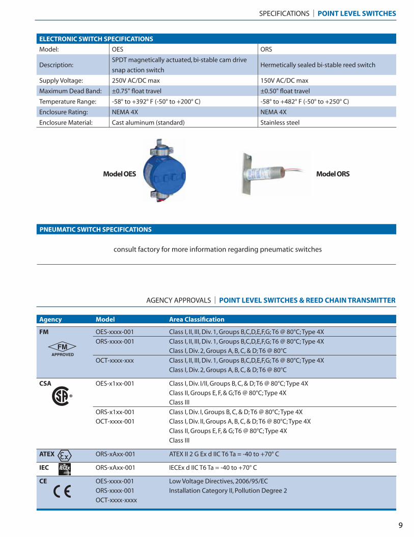
MAGNETIC PARTICLE TRAP
Magnetic Particle Traps, or Magtraps, provide protection for Orion’s line of
Magnetic Level Indicators. Particles composed mostly of ferrite, often from
carbon steel piping, are widespread throughout process piping. These par-
ticles enter the MLI via the process connections during normal fill and drain
operations. The magnetic float located inside the MLI attracts these particles
over time. Eventually, the build-up will be enough to cause the float to be-
come stuck inside the chamber. This results in the MLI either reading inac-
curately or not at all. The trap collects the particles which can be cleaned
periodically to ensure continued operation of the magnetic level indicator.
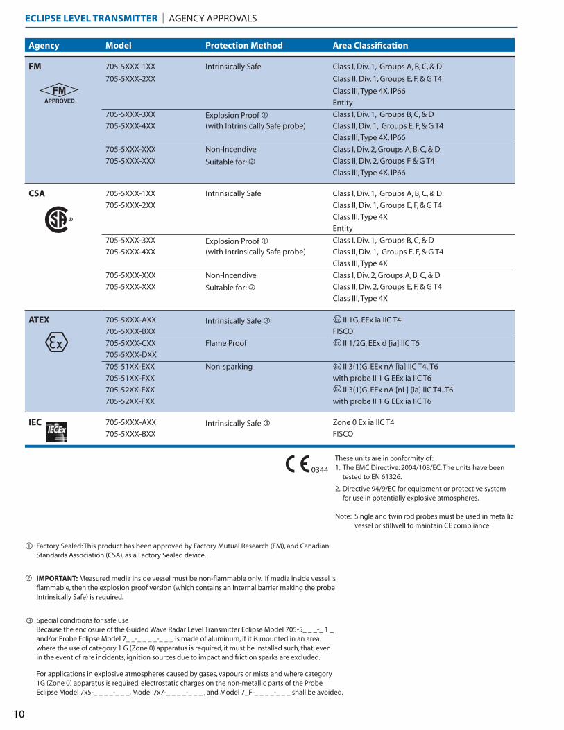
HEAT TRACING: ELECTRIC & STEAM
For applications where process freeze protection or temperature mainte-
nance is required, heat tracing will allow the MLI to operate uninterrupted
throughout harsh, cold conditions.
Electric Heat Tracing is available in self-regulating, constant wattage, and
mineral insulated varieties. Contact the factory for more information.
OPTIONS & ACCESSORIES | MAGNETIC LEVEL INDICATOR
7
TRANSMITTER SPECIFICATIONSEclipse Guided Wave Radar Jupiter Magnetostrictive
Measuring Range: 6 to 240 inches (15 to 610 cm) 6 to 400 inches (15 to 999 cm)
Resolution:0.01 mA analog
0.1 inch (cm) display0.01 mA analog
0.1 inch (cm) display
Repeatability: <0.1 inch (2.5 mm)±0.005% of full span or 0.005 inches (0.127 mm)
(whichever is greater)
Non-Linearity:<0.1% of probe length or 0.1 inch (2.5 mm)
(whichever is greater)0.020% of full span or 0.031 inches (0.794 mm)
(whichever is greater)
Upper Dead Zone: None less than 3 inches (7.6 cm) when bottom mounted electronics
Lower Dead Zone: None less than 3 inches (7.6 cm) when top mounted electronics
Damping: 0 - 10 seconds; adjustable 0 - 25 seconds; adjustable
Power (at terminals):
GP/IS: 11 to 28.6 VDCEP (with IS probe): 13.5 to 28 VDC
FOUNDATION fieldbus™ & PROFIBUS PA™(FISCO): 9 to 17.5 VDCFOUNDATION fieldbus™ & PROFIBUS PA™(FNICO Exd): 9 to 32 VDC
HART®: 12 to 28 VDCFOUNDATION fieldbus™ Explosion Proof: 9 to 17.5 VDC
FISCO/FNICO: 9 to 17.5 VDC
Signal Output:4-20 mA with HART®: 3.8 to 20.5 mA usable
FOUNDATION fieldbus™: H1 (ITK Ver. 5.01)PROFIBUS PA™: PROFIBUS PA™ H1
4-20 mA with HART®: 3.8 to 20.5 mA usableFOUNDATION fieldbus™: H1 (ITK Ver. 4.61)
Display: 2 line x 8 character LCD 2 line x 8 character LCD
Housing Material: IP66/Aluminum A356T6 or 316 SS NEMA 4X/7/9IP66/Aluminum A356T6 or 316 SS
Area Classifications:FM/CSA/ATEX/IEC - EP, IS, NI
(see specific product literature for more detail)FM/CSA/ATEX/IEC/INMETRO - EP, IS, NI
(see specific product literature for more detail)
Safety Integrity Level:Standard Electronics: SIL 1 as 1oo1, SFF 85.4%Enhanced Electronics: SIL 2 as 1oo1, SFF 91%
Standard Electronics: SIL 1 as 1oo1, SFF 83.7%Enhanced Electronics: SIL 2 as 1oo1, SFF 90.7%
Process Temperature:probe dependent
(see specific product literature for more detail)External Mount: -320° F to +850° F Direct Insertion: -320° F to + 500° F
Ambient Temperature at Electronics:
-40° to 175° F (-40° to 80° C)LCD: -5° to +160° F (-20° to +70° C)
-40° to 175° F (-40° to 80° C)LCD: -10° to +160° F (-20° to +70° C)
Process Pressure:probe dependent
(see specific product literature for more detail)Direct insertion: +1700 psig (117 bar)
(see specific product literature for more detail)
Mounting Arrangement:
Direct insertion probe with integral mount or remote mount electronics
Direct insertion probe with integral mount orexternal top or bottom mount on MLI
TRANSMITTER SPECIFICATIONSOCT Reed Chain
Measuring Range: 6 to 198 inches (15 to 503 cm)
Resolution: ±0.50 inches (13 mm)
Repeatability: < 0.25 inches (6 mm)
Non-Linearity: <0.4% full span averaged over span
Upper Transition Zone: 4 inches (10.2 cm)
Lower Transition Zone: 4 inches (10.2 cm)
Power Input: 12 to 36 VDC
Signal Output: 4 to 20 mA
Housing Type: NEMA 4X, IP66
Housing Material: Cast Aluminum or 316 SS
Area Classifications:FM/CSA
EP
Process Temperature:-40° to +425° F
(-40° to +218° C)
Ambient Temperature at Electronics:
-40° to +158° F (-40° to +70° C)
Mounting Arrangement:External mount probe with integral top
or bottom mounted electronics
LEVEL TRANSMITTERS | SPECIFICATIONS
Eclipse® Jupiter™
on Atlas™
OCT on Atlas™
8
PNEUMATIC SWITCH SPECIFICATIONS
consult factory for more information regarding pneumatic switches
SPECIFICATIONS | POINT LEVEL SWITCHES
ELECTRONIC SWITCH SPECIFICATIONS
Model: OES ORS
Description: SPDT magnetically actuated, bi-stable cam drive
snap action switchHermetically sealed bi-stable reed switch
Supply Voltage: 250V AC/DC max 150V AC/DC max
Maximum Dead Band: ±0.75" float travel ±0.50" float travel
Temperature Range: -58° to +392° F (-50° to +200° C) -58° to +482° F (-50° to +250° C)
Enclosure Rating: NEMA 4X NEMA 4X
Enclosure Material: Cast aluminum (standard) Stainless steel
9
AGENCY APPROVALS | POINT LEVEL SWITCHES & REED CHAIN TRANSMITTER
Agency Model Area Classification
FM OES-xxxx-001 Class I, II, III, Div. 1, Groups B,C,D,E,F,G; T6 @ 80°C; Type 4X
ORS-xxxx-001 Class I, II, III, Div. 1, Groups B,C,D,E,F,G; T6 @ 80°C; Type 4X
Class I, Div. 2, Groups A, B, C, & D; T6 @ 80°C
OCT-xxxx-xxx Class I, II, III, Div. 1, Groups B,C,D,E,F,G; T6 @ 80°C; Type 4X
Class I, Div. 2, Groups A, B, C, & D; T6 @ 80°C
CSA OES-x1xx-001 Class I, Div. I/II, Groups B, C, & D; T6 @ 80°C; Type 4X
Class II, Groups E, F, & G;T6 @ 80°C; Type 4X
Class III
ORS-x1xx-001 Class I, Div. I, Groups B, C, & D; T6 @ 80°C; Type 4X
OCT-xxxx-001 Class I, Div. II, Groups A, B, C, & D; T6 @ 80°C; Type 4X
Class II, Groups E, F, & G; T6 @ 80°C; Type 4X
Class III
ATEX ORS-xAxx-001 ATEX II 2 G Ex d IIC T6 Ta = -40 to +70° C
IEC ORS-xAxx-001 IECEx d IIC T6 Ta = -40 to +70° C
CE OES-xxxx-001 Low Voltage Directives, 2006/95/EC
ORS-xxxx-001 Installation Category II, Pollution Degree 2
OCT-xxxx-xxxx
Model OES Model ORS
Factory Sealed: This product has been approved by Factory Mutual Research (FM), and Canadian Standards Association (CSA), as a Factory Sealed device.
These units are in conformity of:1. The EMC Directive: 2004/108/EC. The units have been
tested to EN 61326.
2. Directive 94/9/EC for equipment or protective system for use in potentially explosive atmospheres.
Note: Single and twin rod probes must be used in metallic vessel or stillwell to maintain CE compliance.
IMPORTANT: Measured media inside vessel must be non-flammable only. If media inside vessel is flammable, then the explosion proof version (which contains an internal barrier making the probe Intrinsically Safe) is required.
�
�
Agency Model Protection Method Area Classification
FM 705-5XXX-1XX Intrinsically Safe Class I, Div. 1, Groups A, B, C, & D
705-5XXX-2XX Class II, Div. 1, Groups E, F, & G T4
Class III, Type 4X, IP66
Entity
705-5XXX-3XX Explosion Proof � Class I, Div. 1, Groups B, C, & D
705-5XXX-4XX (with Intrinsically Safe probe) Class II, Div. 1, Groups E, F, & G T4
Class III, Type 4X, IP66
705-5XXX-XXX Non-Incendive Class I, Div. 2, Groups A, B, C, & D
705-5XXX-XXX Suitable for: � Class II, Div. 2, Groups F & G T4
Class III, Type 4X, IP66
CSA 705-5XXX-1XX Intrinsically Safe Class I, Div. 1, Groups A, B, C, & D
705-5XXX-2XX Class II, Div. 1, Groups E, F, & G T4
Class III, Type 4X
Entity
705-5XXX-3XX Explosion Proof � Class I, Div. 1, Groups B, C, & D
705-5XXX-4XX (with Intrinsically Safe probe) Class II, Div. 1, Groups E, F, & G T4
Class III, Type 4X
705-5XXX-XXX Non-Incendive Class I, Div. 2, Groups A, B, C, & D
705-5XXX-XXX Suitable for: � Class II, Div. 2, Groups E, F, & G T4
Class III, Type 4X
ATEX 705-5XXX-AXX Intrinsically Safe � II 1G, EEx ia IIC T4
705-5XXX-BXX FISCO
705-5XXX-CXX Flame Proof II 1/2G, EEx d [ia] IIC T6
705-5XXX-DXX
705-51XX-EXX Non-sparking II 3(1)G, EEx nA [ia] IIC T4..T6
705-51XX-FXX with probe II 1 G EEx ia IIC T6
705-52XX-EXX II 3(1)G, EEx nA [nL] [ia] IIC T4..T6
705-52XX-FXX with probe II 1 G EEx ia IIC T6
IEC 705-5XXX-AXX Intrinsically Safe � Zone 0 Ex ia IIC T4
705-5XXX-BXX FISCO
ECLIPSE LEVEL TRANSMITTER | AGENCY APPROVALS
Special conditions for safe useBecause the enclosure of the Guided Wave Radar Level Transmitter Eclipse Model 705-5_ _ _-_ 1 _and/or Probe Eclipse Model 7_ _-_ _ _ _-_ _ _ is made of aluminum, if it is mounted in an areawhere the use of category 1 G (Zone 0) apparatus is required, it must be installed such, that, evenin the event of rare incidents, ignition sources due to impact and friction sparks are excluded.
For applications in explosive atmospheres caused by gases, vapours or mists and where category1G (Zone 0) apparatus is required, electrostatic charges on the non-metallic parts of the ProbeEclipse Model 7x5-_ _ _ _-_ _ _, Model 7x7-_ _ _ _-_ _ _ , and Model 7_F-_ _ _ _-_ _ _ shall be avoided.
�
0344
10
11
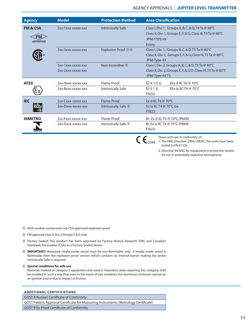
Agency Model Protection Method Area Classification
FM & CSA 2xx-1xxx-xxxxx-xxx Intrinsically Safe Class I, Div. 1, Groups A, B, C, & D, T4 Ta @ 80°C
Class II, Div. 1, Groups E, F, & G; Class III, T4 Ta @ 80°C
IP66 TYPE 4X
Entity
2xx-3xxx-xxxxx-xxx Explosion Proof �� Class I, Div. 1, Groups B, C, & D, T5 Ta @ 80°C
Class II, Div. 1, Groups E, F, & G; Class III, T5 Ta @ 80°C
IP66 Type 4X
2xx-1xxx-xxxxx-xxx Non-Incendive � Class I, Div. 2, Groups A, B, C, & D, T5 Ta @ 80°C
2xx-2xxx-xxxxx-xxx Class II, Div. 2, Groups E, F, & G�; Class III, T5 Ta @ 80°C
IP66 Type 4X T5
ATEX 2xx-Axxx-xxxxx-xxx Flame Proof II 1/2 G EEx d IIC T6 @ 70°C
2xx-Bxxx-xxxxx-xxx Intrinsically Safe II 1 G EEx ia IIC T4 @ 70°C
FISCO
IEC 2xx-Cxxx-xxxxx-xxx Flame Proof Ex d IIC T6 @ 70°C
2xx-Dxxx-xxxxx-xxx Intrinsically Safe � Ex ia IIC T4 @ 70°C Ga
FISCO
INMETRO 2xx-Fxxx-xxxxx-xxx Flame Proof Br- Ex d IIC T6 @ 70°C, IP66W
2xx-Gxxx-xxxxx-xxx Intrinsically Safe � Br-Ex ia IIC T4 @ 70°C, IP66W
FISCO
AGENCY APPROVALS | JUPITER LEVEL TRANSMITTER
Factory Sealed: This product has been approved by Factory Mutual Research (FM), and Canadian Standards Association (CSA), as a Factory Sealed device.
These units are in conformity of:1. The EMC Directive: 2004/108/EC. The units have been
tested to EN 61326.
2. Directive 94/9/EC for equipment or protective system for use in potentially explosive atmospheres.
IMPORTANT: Measured media inside vessel must be non-flammable only. If media inside vessel is flammable, then the explosion proof version (which contains an internal barrier making the probe Intrinsically Safe) is required.
�
�
Special conditions for safe useMaterials marked as category 1 equipment and used in hazardous areas requiring this category, shall be installed in such a way that, even in the event of rare incidents, the aluminum enclosure cannot be an ignition source due to impact or friction.
�
FM approval class II, Div. 2 Groups F & G only�
M20 conduit connections not CSA approved explosion proof�
0344
ADDITIONAL CERTIFIC ATIONS
GOST R Russian Certificate of Conformity
GOST Pattern Approval Certificate for Measuring Instruments (Metrology Certificate)
GOST R Ex-Proof Certificate of Conformity

1 2 3 4 5 6 7 8 9 10 11 12 13 14 15 16 17 18 19 20 21 22 23 24 25
MAGNETIC LEVEL INDICATOR | MODEL NUMBER
1 Atlas MLI
2 Aurora MLI with Eclipse® GWR transmitter
3 Gemini dual-chamber MLI with Eclipse® GWR
4 Stratus MLI
5 External Cage for Jupiter® transmitter
1 PRODUCT TYPE
E English Units (Inches) Specifies the unit of measure for the ����������������and �� ������ ���������� (digits 18 - 20)M Metric Units (Centimeters)
2 UNIT OF MEASURE
Process Connection Orientation Chamber Top Chamber Bottom
1 Side / Side Dome cap Flanged (including mating blind flange)
2 Side / Side Flanged (including mating blind flange) Dome cap
3 Side / Side Flanged (including mating blind flange) Flanged (including mating blind flange)
4 Top / Bottom Flanged Flanged
5 Top / Bottom with Spool Pieces Flanged (including mating blind flange) Flanged (including mating blind flange)
6 Top / Side Flanged Flanged (including mating blind flange)
7 Top / Side Dome cap with process connection Flanged (including mating blind flange)
8 Side / Bottom Flanged (including mating blind flange) Flanged
9 Side / Bottom Flanged (including mating blind flange) Dome cap with process connection
T Top Mount Threaded cap Flanged process connection �
31 ATLAS - CHAMBER CONFIGURATION
Process Connection Orientation Chamber Top Chamber Bottom
1 Side / Side Welded cap with threaded Eclipse probe Flanged (including mating blind flange)
2 Side / Side Flanged with threaded Eclipse probe Dome cap
3 Side / Side Flanged with threaded Eclipse probe Flanged (including mating blind flange)
4 Side / Side Flanged with seal welded Eclipse probe Dome cap
5 Side / Side Flanged with seal welded Eclipse probe Flanged (including mating blind flange)
A Side / Bottom Welded cap with threaded Eclipse probe Flanged with process connection
B Side / Bottom Flanged with threaded Eclipse probe Dome cap with process connection
C Side / Bottom Flanged with threaded Eclipse probe Flanged with process connection
D Side / Bottom Flanged with seal welded Eclipse probe Dome cap with process connection
F Side / Bottom Flanged with seal welded Eclipse probe Flanged with process connection
32 AURORA - CHAMBER CONFIGURATION
Process ConnectionOrientation
Primary Chamber Top Primary Chamber BottomSecondary Chamber (with Eclipse GWR transmitter) �
Top Bottom
1 Side / Side Dome cap Flanged (with blind) Dome cap with threaded Eclipse Dome cap
2 Side / Side Flanged (with blind) Dome cap Dome cap with threaded Eclipse Dome cap
3 Side / Side Flanged (with blind) Flanged (with blind) Dome cap with threaded Eclipse Dome cap
4 Side / Side Dome cap Flanged (with blind) Flanged with threaded Eclipse Dome cap
5 Side / Side Flanged (with blind) Dome cap Flanged with threaded Eclipse Dome cap
6 Side / Side Flanged (with blind) Flanged (with blind) Flanged with threaded Eclipse Dome cap
7 Side / Side Dome cap Flanged (with blind) Flanged with threaded Eclipse Flanged (with blind)
8 Side / Side Flanged (with blind) Dome cap Flanged with threaded Eclipse Flanged (with blind)
9 Side / Side Flanged (with blind) Flanged (with blind) Flanged with threaded Eclipse Flanged (with blind)
A Top / Bottom Flanged Flanged Dome cap with threaded Eclipse Dome cap
B Top / Bottom Flanged Flanged Flanged with threaded Eclipse Dome cap
C Top / Bottom Flanged Flanged Flanged with threaded Eclipse Flanged (with blind)
33 GEMINI - CHAMBER CONFIGURATION
consult factory for seal welded Eclipse probe in secondary chamber�12
Select the appropriate Chamber Configuration from the following five tables (match product type from digit 1)
See pg. 19 for additional mounting options, or consult factory for custom solutions.�
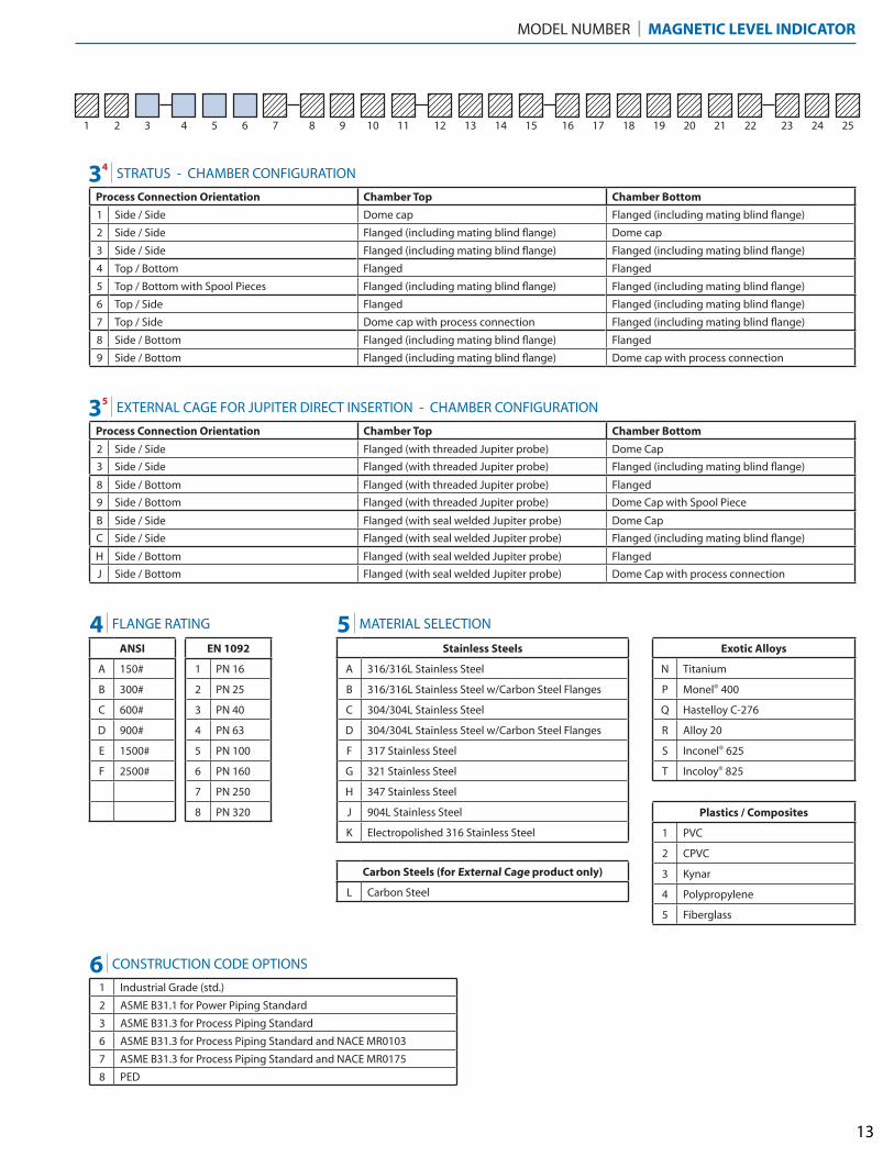
ANSI
A 150#
B 300#
C 600#
D 900#
E 1500#
F 2500#
EN 1092
1 PN 16
2 PN 25
3 PN 40
4 PN 63
5 PN 100
6 PN 160
7 PN 250
8 PN 320
Stainless Steels
A 316/316L Stainless Steel
B 316/316L Stainless Steel w/Carbon Steel Flanges
C 304/304L Stainless Steel
D 304/304L Stainless Steel w/Carbon Steel Flanges
F 317 Stainless Steel
G 321 Stainless Steel
H 347 Stainless Steel
J 904L Stainless Steel
K Electropolished 316 Stainless Steel
Exotic Alloys
N Titanium
P Monel® 400
Q Hastelloy C-276
R Alloy 20
S Inconel® 625
T Incoloy® 825
Plastics / Composites
1 PVC
2 CPVC
3 Kynar
4 Polypropylene
5 Fiberglass
Carbon Steels (for External Cage product only)
L Carbon Steel
1 Industrial Grade (std.)
2 ASME B31.1 for Power Piping Standard
3 ASME B31.3 for Process Piping Standard
6 ASME B31.3 for Process Piping Standard and NACE MR0103
7 ASME B31.3 for Process Piping Standard and NACE MR0175
8 PED
1 2 3 4 5 6 7 8 9 10 11 12 13 14 15 16 17 18 19 20 21 22 23 24 25
MODEL NUMBER | MAGNETIC LEVEL INDICATOR
34 STRATUS - CHAMBER CONFIGURATION
Process Connection Orientation Chamber Top Chamber Bottom
1 Side / Side Dome cap Flanged (including mating blind flange)
2 Side / Side Flanged (including mating blind flange) Dome cap
3 Side / Side Flanged (including mating blind flange) Flanged (including mating blind flange)
4 Top / Bottom Flanged Flanged
5 Top / Bottom with Spool Pieces Flanged (including mating blind flange) Flanged (including mating blind flange)
6 Top / Side Flanged Flanged (including mating blind flange)
7 Top / Side Dome cap with process connection Flanged (including mating blind flange)
8 Side / Bottom Flanged (including mating blind flange) Flanged
9 Side / Bottom Flanged (including mating blind flange) Dome cap with process connection
35 EXTERNAL CAGE FOR JUPITER DIRECT INSERTION - CHAMBER CONFIGURATION
Process Connection Orientation Chamber Top Chamber Bottom
2 Side / Side Flanged (with threaded Jupiter probe) Dome Cap
3 Side / Side Flanged (with threaded Jupiter probe) Flanged (including mating blind flange)
8 Side / Bottom Flanged (with threaded Jupiter probe) Flanged
9 Side / Bottom Flanged (with threaded Jupiter probe) Dome Cap with Spool Piece
B Side / Side Flanged (with seal welded Jupiter probe) Dome Cap
C Side / Side Flanged (with seal welded Jupiter probe) Flanged (including mating blind flange)
H Side / Bottom Flanged (with seal welded Jupiter probe) Flanged
J Side / Bottom Flanged (with seal welded Jupiter probe) Dome Cap with process connection
4 FLANGE RATING 5 MATERIAL SELECTION
6 CONSTRUCTION CODE OPTIONS
13
1 2 3 4 5 6 7 8 9 10 11 12 13 14 15 16 17 18 19 20 21 22 23 24 25
MAGNETIC LEVEL INDICATOR | MODEL NUMBER
14
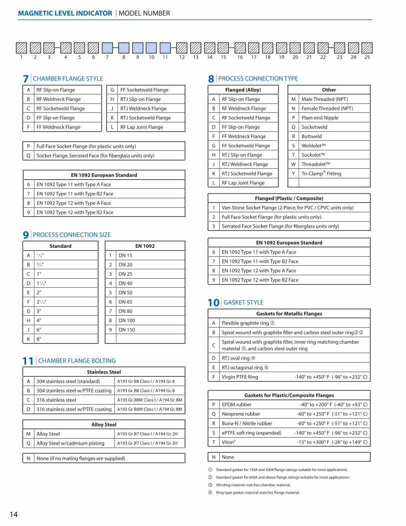
Standard gasket for 150# and 300# flange ratings suitable for most applications.
Standard gasket for 600# and above flange ratings suitable for most applications.
�
�Winding material matches chamber material.�Ring type gasket material matches flange material.�
A RF Slip-on Flange
B RF Weldneck Flange
C RF Socketweld Flange
D FF Slip-on Flange
F FF Weldneck Flange
Flanged (Alloy)
A RF Slip-on Flange
B RF Weldneck Flange
C RF Socketweld Flange
D FF Slip-on Flange
F FF Weldneck Flange
G FF Socketweld Flange
H RTJ Slip-on Flange
J RTJ Weldneck Flange
K RTJ Socketweld Flange
L RF Lap Joint Flange
Other
M Male Threaded (NPT)
N Female Threaded (NPT)
P Plain-end Nipple
Q Socketweld
R Buttweld
S Weldolet™
T Sockolet™
W Threadolet™
Y Tri-Clamp® Fitting
Flanged (Plastic / Composite)
1 Van-Stone Socket Flange (2-Piece, for PVC / CPVC units only)
2 Full Face Socket Flange (for plastic units only)
3 Serrated Face Socket Flange (for fiberglass units only)
Standard
A 1⁄2"
B 3⁄4"
C 1"
D 11⁄2"
E 2"
F 21⁄2"
G 3"
H 4"
J 6"
K 8"
EN 1092
1 DN 15
2 DN 20
3 DN 25
4 DN 40
5 DN 50
6 DN 65
7 DN 80
8 DN 100
9 DN 150
Gaskets for Metallic Flanges
A Flexible graphite ring �
B Spiral wound with graphite filler and carbon steel outer ring��
CSpiral wound with graphite filler, inner ring matching chamber material �, and carbon steel outer ring
D RTJ oval ring �
E RTJ octagonal ring �
F Virgin PTFE Ring -140° to +450° F (-96° to +232° C)Stainless Steel
A 304 stainless steel (standard) A193 Gr. B8 Class I / A194 Gr. 8
B 304 stainless steel w/PTFE coating A193 Gr. B8 Class I / A194 Gr. 8
C 316 stainless steel A193 Gr. B8M Class I / A194 Gr. 8M
D 316 stainless steel w/PTFE coating A193 Gr. B8M Class I / A194 Gr. 8M
Alloy Steel
M Alloy Steel A193 Gr. B7 Class I / A194 Gr. 2H
Q Alloy Steel w/cadmium plating A193 Gr. B7 Class I / A194 Gr. 2H
P Full Face Socket Flange (for plastic units only)
Q Socket Flange, Serrated Face (for fiberglass units only)
Gaskets for Plastic/Composite Flanges
P EPDM rubber -40° to +200° F (-40° to +93° C)
Q Neoprene rubber -60° to +250° F (-51° to +121° C)
R Buna-N / Nitrile rubber -60° to +250° F (-51° to +121° C)
S ePTFE soft ring (expanded) -140° to +450° F (-96° to +232° C)
T Viton® -15° to +300° F (-26° to +149° C)
7 CHAMBER FLANGE STYLE 8 PROCESS CONNECTION TYPE
10 GASKET STYLE
9 PROCESS CONNECTION SIZE
11 CHAMBER FLANGE BOLTING
EN 1092 European Standard
6 EN 1092 Type 11 with Type A Face
7 EN 1092 Type 11 with Type B2 Face
8 EN 1092 Type 12 with Type A Face
9 EN 1092 Type 12 with Type B2 Face
EN 1092 European Standard
6 EN 1092 Type 11 with Type A Face
7 EN 1092 Type 11 with Type B2 Face
8 EN 1092 Type 12 with Type A Face
9 EN 1092 Type 12 with Type B2 Face
G FF Socketweld Flange
H RTJ Slip-on Flange
J RTJ Weldneck Flange
K RTJ Socketweld Flange
L RF Lap Joint Flange
N None (if no mating flanges are supplied) N None
1 2 3 4 5 6 7 8 9 10 11 12 13 14 15 16 17 18 19 20 21 22 23 24 25
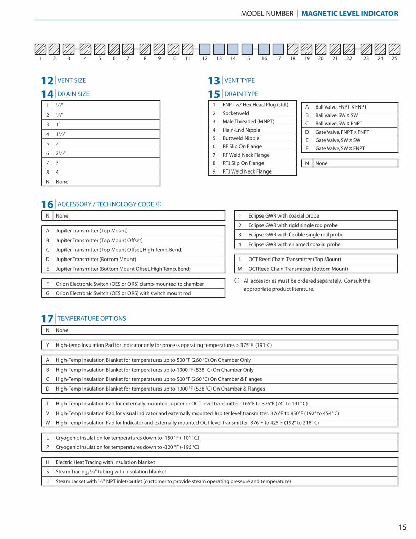
1 1⁄2"
2 3⁄4"
3 1"
4 11⁄2"
5 2"
6 21⁄2"
7 3"
8 4"
N None
1 FNPT w/ Hex Head Plug (std.)
2 Socketweld
3 Male Threaded (MNPT)
4 Plain-End Nipple
5 Buttweld Nipple
6 RF Slip On Flange
7 RF Weld Neck Flange
8 RTJ Slip On Flange
9 RTJ Weld Neck Flange
A Ball Valve, FNPT x FNPT
B Ball Valve, SW x SW
C Ball Valve, SW x FNPT
D Gate Valve, FNPT x FNPT
E Gate Valve, SW x SW
F Gate Valve, SW x FNPT
N None
N None
A Jupiter Transmitter (Top Mount)
B Jupiter Transmitter (Top Mount Offset)
C Jupiter Transmitter (Top Mount Offset, High Temp. Bend)
D Jupiter Transmitter (Bottom Mount)
E Jupiter Transmitter (Bottom Mount Offset, High Temp. Bend)
F Orion Electronic Switch (OES or ORS) clamp-mounted to chamber
G Orion Electronic Switch (OES or ORS) with switch mount rod
1 Eclipse GWR with coaxial probe
2 Eclipse GWR with rigid single rod probe
3 Eclipse GWR with flexible single rod probe
4 Eclipse GWR with enlarged coaxial probe
L OCT Reed Chain Transmitter (Top Mount)
M OCTReed Chain Transmitter (Bottom Mount)
N None
Y High-temp Insulation Pad for indicator only for process operating temperatures > 375°F (191°C)
A High-Temp Insulation Blanket for temperatures up to 500 °F (260 °C) On Chamber Only
B High-Temp Insulation Blanket for temperatures up to 1000 °F (538 °C) On Chamber Only
C High-Temp Insulation Blanket for temperatures up to 500 °F (260 °C) On Chamber & Flanges
D High-Temp Insulation Blanket for temperatures up to 1000 °F (538 °C) On Chamber & Flanges
T High-Temp Insulation Pad for externally mounted Jupiter or OCT level transmitter. 165°F to 375°F (74° to 191° C)
V High-Temp Insulation Pad for visual indicator and externally mounted Jupiter level transmitter. 376°F to 850°F (192° to 454° C)
W High-Temp Insulation Pad for Indicator and externally mounted OCT level transmitter. 376°F to 425°F (192° to 218° C)
L Cryogenic Insulation for temperatures down to -150 °F (-101 °C)
P Cryogenic Insulation for temperatures down to -320 °F (-196 °C)
H Electric Heat Tracing with insulation blanket
S Steam Tracing, 3⁄8" tubing with insulation blanket
J Steam Jacket with 1⁄2" NPT inlet/outlet (customer to provide steam operating pressure and temperature)
All accessories must be ordered separately. Consult the
appropriate product literature.
MODEL NUMBER | MAGNETIC LEVEL INDICATOR
12 VENT SIZE
14 DRAIN SIZE
13 VENT TYPE
15 DRAIN TYPE
16 ACCESSORY / TECHNOLOGY CODE �
17 TEMPERATURE OPTIONS
15
�
1 2 3 4 5 6 7 8 9 10 11 12 13 14 15 16 17 18 19 20 21 22 23 24 25
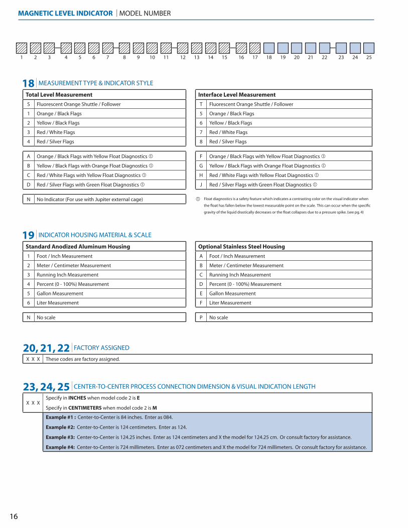
Total Level Measurement
S Fluorescent Orange Shuttle / Follower
1 Orange / Black Flags
2 Yellow / Black Flags
3 Red / White Flags
4 Red / Silver Flags
A Orange / Black Flags with Yellow Float Diagnostics �
B Yellow / Black Flags with Orange Float Diagnostics �
C Red / White Flags with Yellow Float Diagnostics �
D Red / Silver Flags with Green Float Diagnostics �
N No Indicator (For use with Jupiter external cage)
Standard Anodized Aluminum Housing
1 Foot / Inch Measurement
2 Meter / Centimeter Measurement
3 Running Inch Measurement
4 Percent (0 - 100%) Measurement
5 Gallon Measurement
6 Liter Measurement
N No scale
Interface Level Measurement
T Fluorescent Orange Shuttle / Follower
5 Orange / Black Flags
6 Yellow / Black Flags
7 Red / White Flags
8 Red / Silver Flags
F Orange / Black Flags with Yellow Float Diagnostics �
G Yellow / Black Flags with Orange Float Diagnostics �
H Red / White Flags with Yellow Float Diagnostics �
J Red / Silver Flags with Green Float Diagnostics �
X X XSpecify in INCHES when model code 2 is E
Specify in CENTIMETERS when model code 2 is M
Example #1 : Center-to-Center is 84 inches. Enter as 084.
Example #2: Center-to-Center is 124 centimeters. Enter as 124.
Example #3: Center-to-Center is 124.25 inches. Enter as 124 centimeters and X the model for 124.25 cm. Or consult factory for assistance.
Example #4: Center-to-Center is 724 millimeters. Enter as 072 centimeters and X the model for 724 millimeters. Or consult factory for assistance.
X X X These codes are factory assigned.
MAGNETIC LEVEL INDICATOR | MODEL NUMBER
Optional Stainless Steel Housing
A Foot / Inch Measurement
B Meter / Centimeter Measurement
C Running Inch Measurement
D Percent (0 - 100%) Measurement
E Gallon Measurement
F Liter Measurement
P No scale
18 MEASUREMENT TYPE & INDICATOR STYLE
19 INDICATOR HOUSING MATERIAL & SCALE
20, 21, 22 FACTORY ASSIGNED
23, 24, 25 CENTER-TO-CENTER PROCESS CONNECTION DIMENSION & VISUAL INDICATION LENGTH
16
Float diagnostics is a safety feature which indicates a contrasting color on the visual indicator when
the float has fallen below the lowest measurable point on the scale. This can occur when the specific
gravity of the liquid drastically decreases or the float collapses due to a pressure spike. (see pg. 4)
�
17
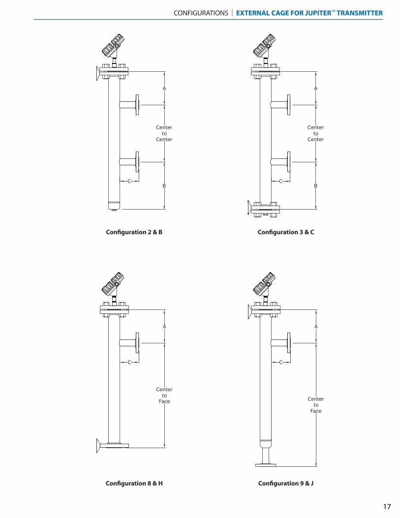
CONFIGURATIONS | EXTERNAL CAGE FOR JUPITER™ TRANSMITTER
A
B
A
B
Centerto
Center
Centerto
Center
A
CentertoFace
A
CentertoFace
C C
C C
Configuration 2 & B Configuration 3 & C
Configuration 8 & H Configuration 9 & J
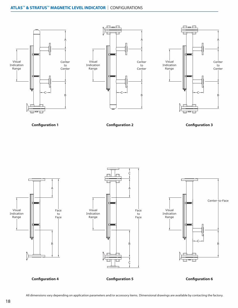
ATLAS™ & STRATUS™ MAGNETIC LEVEL INDICATOR | CONFIGURATIONS
A
BC
A
B
A
B
A
B
FacetoFace
C
C
VisualIndicationRange
B
Center-to-Face
VisualIndicationRange
VisualIndicationRange
VisualIndicationRange
VisualIndicationRange
VisualIndicationRange
FacetoFace
Centerto
Center
Centerto
Center
Centerto
Center
A
B
C C
C
18
Configuration 4 Configuration 5 Configuration 6
Configuration 1 Configuration 2 Configuration 3
All dimensions vary depending on application parameters and/or accessory items. Dimensional drawings are available by contacting the factory.
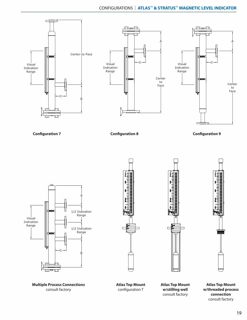
CONFIGURATIONS | ATLAS™ & STRATUS™ MAGNETIC LEVEL INDICATOR
VisualIndicationRange
B
Center-to-Face
A
CentertoFace
VisualIndicationRange
A
CentertoFace
VisualIndicationRange
BAT ON ROUGE, LAPHONE 1-225-906-2343
F AX 1-225-906-2344WWW.ORIONINSTRUMENTS.COM
C
C C
A
BC
VisualIndicationRange
1/2 IndicationRange
1/2 IndicationRange
BAT ON ROUGE, LAPHONE 1-225-906-2343
F AX 1-225-906-2344WWW.ORIONINSTRUMENTS.COM
19
Multiple Process Connectionsconsult factory
Atlas Top Mountconfiguration T
Atlas Top Mountw/stilling wellconsult factory
Configuration 7 Configuration 8 Configuration 9
Atlas Top Mountw/threaded process
connectionconsult factory
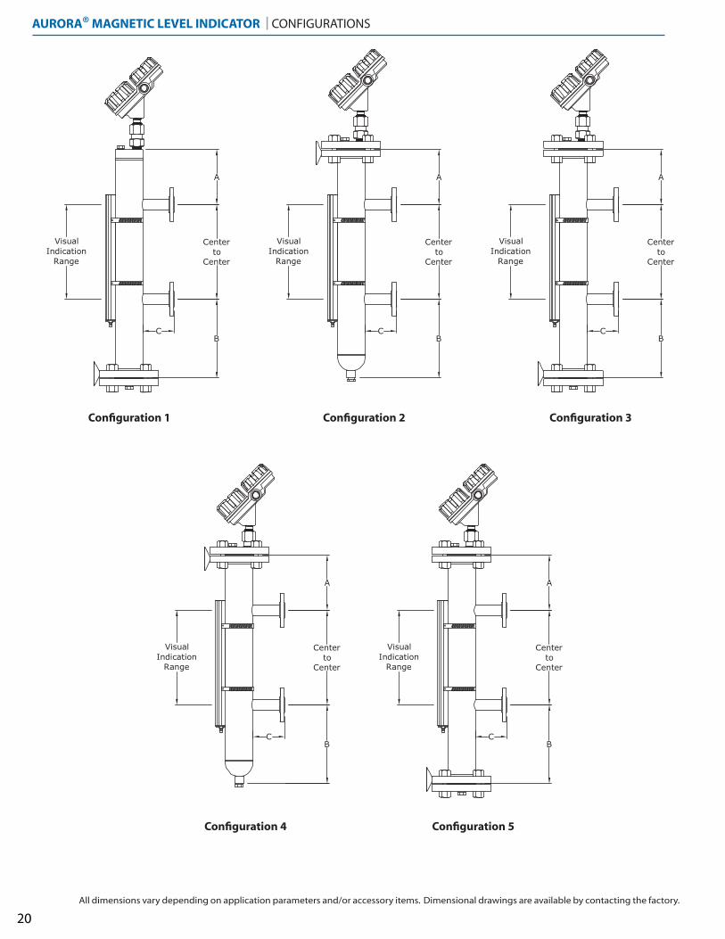
AURORA® MAGNETIC LEVEL INDICATOR | CONFIGURATIONS
VisualIndicationRange
VisualIndicationRange
VisualIndicationRange
A
B
Centerto
Center
VisualIndicationRange
VisualIndicationRange
A
B
Centerto
Center
A
B
Centerto
Center
A
B
Centerto
Center
A
B
Centerto
Center
C C C
C C
20
Configuration 4 Configuration 5
Configuration 1 Configuration 2 Configuration 3
All dimensions vary depending on application parameters and/or accessory items. Dimensional drawings are available by contacting the factory.
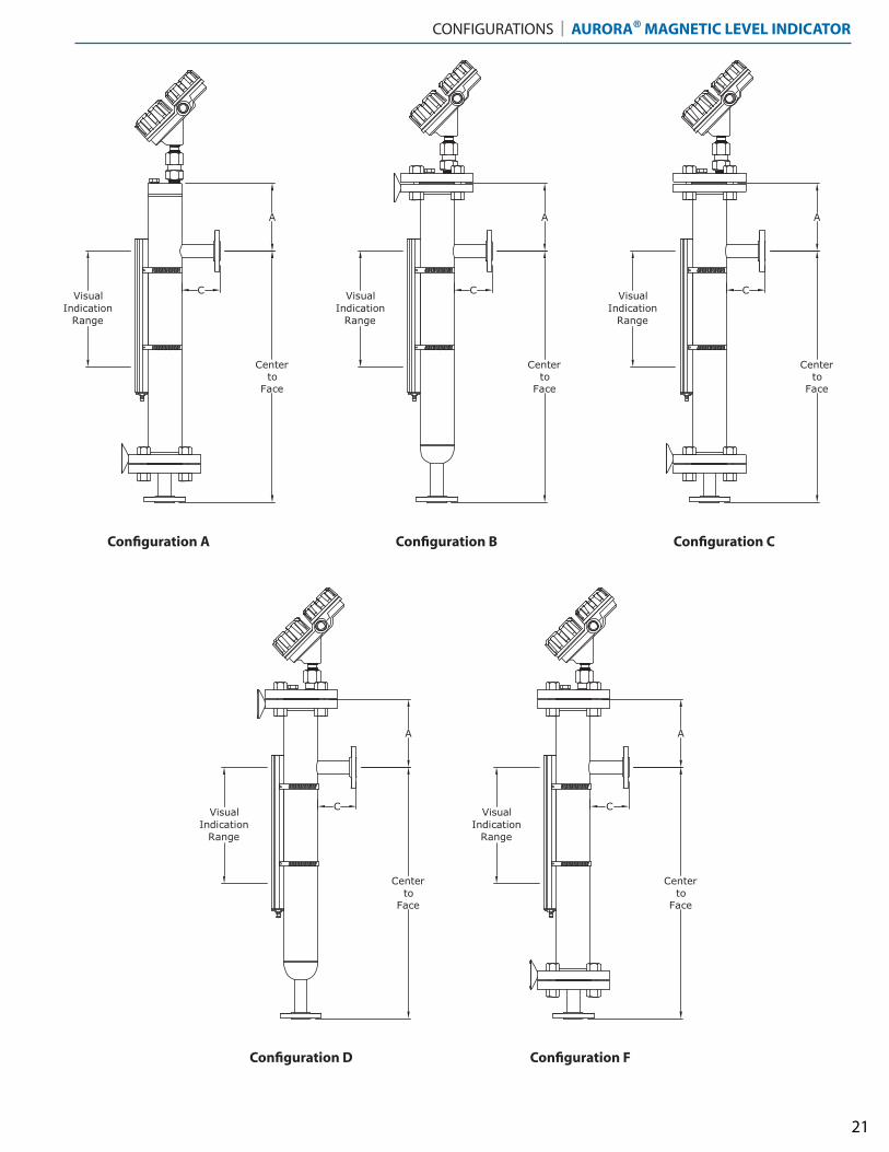
CONFIGURATIONS | AURORA® MAGNETIC LEVEL INDICATOR
VisualIndicationRange
VisualIndicationRange
VisualIndicationRange
A A
CentertoFace
C
CentertoFace
C
A
CentertoFace
C
VisualIndicationRange
VisualIndicationRange
A
CentertoFace
C
A
CentertoFace
C
21
Configuration D Configuration F
Configuration A Configuration B Configuration C
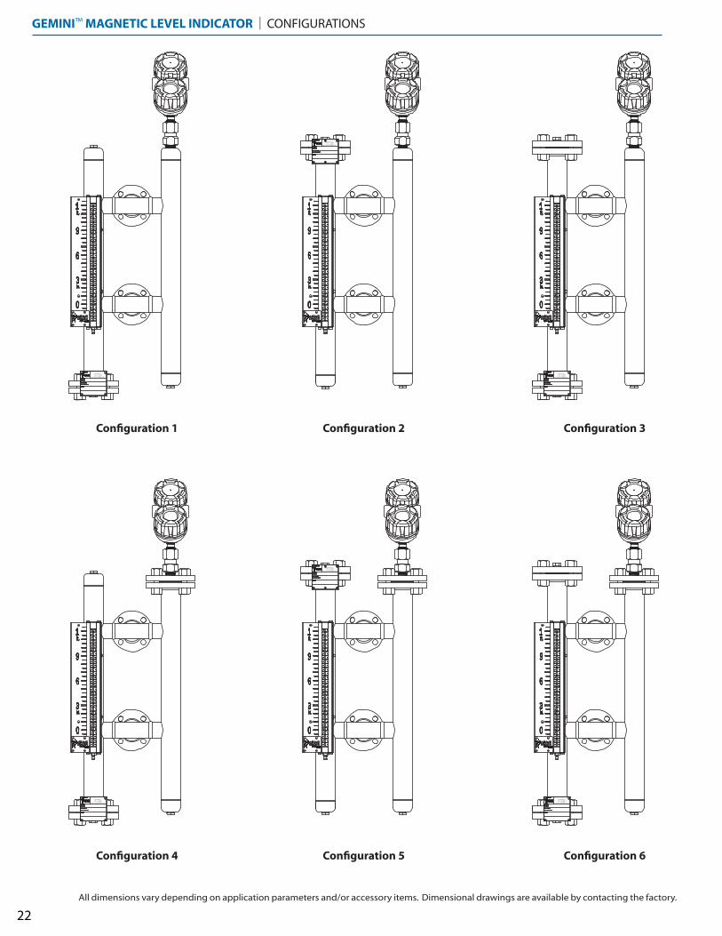
GEMINI™ MAGNETIC LEVEL INDICATOR | CONFIGURATIONS
BAT ON ROUGE, LAPHONE 1-225-906-2343
F AX 1-225-906-2344WWW.ORIONINSTRUMENTS.COM
BAT ON ROUGE, LAPHONE 1-225-906-2343
F AX 1-225-906-2344WWW.ORIONINSTRUMENTS.COM
BAT ON ROUGE, LAPHONE 1-225-906-2343
F AX 1-225-906-2344WWW.ORIONINSTRUMENTS.COM
BAT ON ROUGE, LAPHONE 1-225-906-2343
F AX 1-225-906-2344WWW.ORIONINSTRUMENTS.COM
BAT ON ROUGE, LAPHONE 1-225-906-2343
F AX 1-225-906-2344WWW.ORIONINSTRUMENTS.COM
BAT ON ROUGE, LAPHONE 1-225-906-2343
F AX 1-225-906-2344WWW.ORIONINSTRUMENTS.COM
22
Configuration 4 Configuration 5 Configuration 6
Configuration 1 Configuration 2 Configuration 3
All dimensions vary depending on application parameters and/or accessory items. Dimensional drawings are available by contacting the factory.
CONFIGURATIONS | GEMINI™ MAGNETIC LEVEL INDICATOR
BAT ON ROUGE, LAPHONE 1-225-906-2343
F AX 1-225-906-2344WWW.ORIONINSTRUMENTS.COM
BAT ON ROUGE, LAPHONE 1-225-906-2343
F AX 1-225-906-2344WWW.ORIONINSTRUMENTS.COM
BAT ON ROUGE, LAPHONE 1-225-906-2343
F AX 1-225-906-2344WWW.ORIONINSTRUMENTS.COM
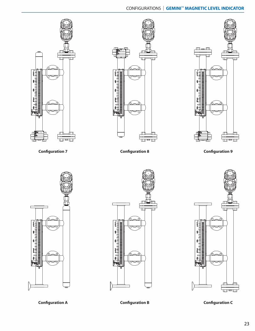
23
Configuration A Configuration B Configuration C
Configuration 7 Configuration 8 Configuration 9
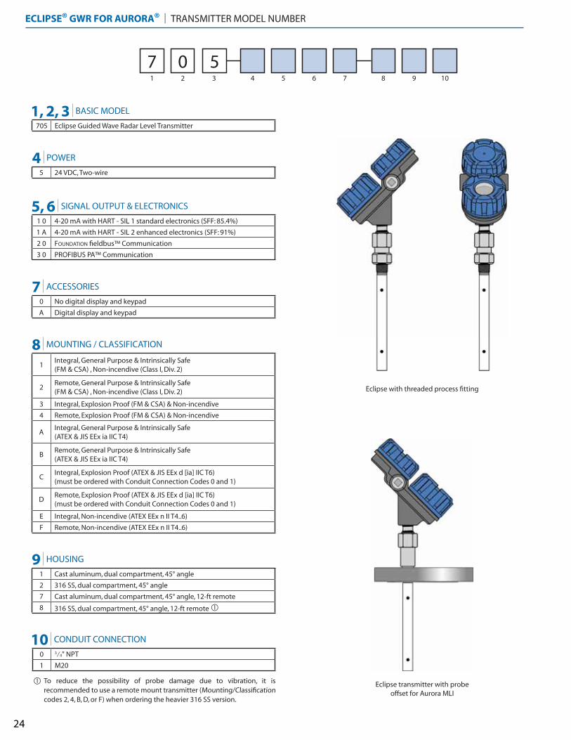
ECLIPSE® GWR FOR AURORA® | TRANSMITTER MODEL NUMBER
24
Eclipse with threaded process fitting
Eclipse transmitter with probe offset for Aurora MLI
1 2 3 4 5 6 7 8 9 10
7 0 5
5 24 VDC, Two-wire
1 0 4-20 mA with HART - SIL 1 standard electronics (SFF: 85.4%)
1 A 4-20 mA with HART - SIL 2 enhanced electronics (SFF: 91%)
2 0 FOUNDATION fieldbus™ Communication
3 0 PROFIBUS PA™ Communication
0 No digital display and keypad
A Digital display and keypad
1 Cast aluminum, dual compartment, 45° angle
2 316 SS, dual compartment, 45° angle
7 Cast aluminum, dual compartment, 45° angle, 12-ft remote
8 316 SS, dual compartment, 45° angle, 12-ft remote �
1Integral, General Purpose & Intrinsically Safe (FM & CSA) , Non-incendive (Class I, Div. 2)
2Remote, General Purpose & Intrinsically Safe (FM & CSA) , Non-incendive (Class I, Div. 2)
3 Integral, Explosion Proof (FM & CSA) & Non-incendive
4 Remote, Explosion Proof (FM & CSA) & Non-incendive
AIntegral, General Purpose & Intrinsically Safe (ATEX & JIS EEx ia IIC T4)
BRemote, General Purpose & Intrinsically Safe (ATEX & JIS EEx ia IIC T4)
CIntegral, Explosion Proof (ATEX & JIS EEx d [ia] IIC T6) (must be ordered with Conduit Connection Codes 0 and 1)
DRemote, Explosion Proof (ATEX & JIS EEx d [ia] IIC T6) (must be ordered with Conduit Connection Codes 0 and 1)
E Integral, Non-incendive (ATEX EEx n II T4..6)
F Remote, Non-incendive (ATEX EEx n II T4..6)
0 3⁄4" NPT
1 M20
1, 2, 3 BASIC MODEL
705 Eclipse Guided Wave Radar Level Transmitter
4
5, 6
7
9
8
POWER
SIGNAL OUTPUT & ELECTRONICS
ACCESSORIES
HOUSING
MOUNTING / CLASSIFICATION
10 CONDUIT CONNECTION
To reduce the possibility of probe damage due to vibration, it is recommended to use a remote mount transmitter (Mounting/Classification codes 2, 4, B, D, or F) when ordering the heavier 316 SS version.
�
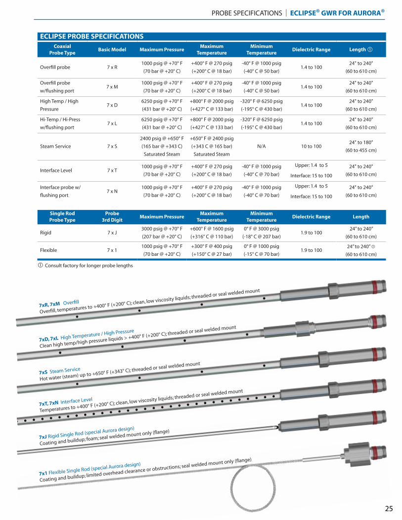
PROBE SPECIFICATIONS | ECLIPSE® GWR FOR AURORA®
25
ECLIPSE PROBE SPECIFICATIONSCoaxial
Probe TypeBasic Model Maximum Pressure
Maximum Temperature
Minimum Temperature
Dielectric Range Length �
Overfill probe 7 x R1000 psig @ +70° F
(70 bar @ +20° C)
+400° F @ 270 psig
(+200° C @ 18 bar)
-40° F @ 1000 psig
(-40° C @ 50 bar) 1.4 to 100
24" to 240"
(60 to 610 cm)
Overfill probe
w/flushing port7 x M
1000 psig @ +70° F
(70 bar @ +20° C)
+400° F @ 270 psig
(+200° C @ 18 bar)
-40° F @ 1000 psig
(-40° C @ 50 bar) 1.4 to 100
24" to 240"
(60 to 610 cm)
High Temp / High
Pressure7 x D
6250 psig @ +70° F
(431 bar @ +20° C)
+800° F @ 2000 psig
(+427° C @ 133 bar)
-320° F @ 6250 psig
(-195° C @ 430 bar) 1.4 to 100
24" to 240"
(60 to 610 cm)
Hi-Temp / Hi-Press
w/flushing port7 x L
6250 psig @ +70° F
(431 bar @ +20° C)
+800° F @ 2000 psig
(+427° C @ 133 bar)
-320° F @ 6250 psig
(-195° C @ 430 bar) 1.4 to 100
24" to 240"
(60 to 610 cm)
Steam Service 7 x S
2400 psig @ +650° F
(165 bar @ +343 C)
Saturated Steam
+650° F @ 2400 psig
(+343 C @ 165 bar)
Saturated Steam
N/A 10 to 100 24" to 180"
(60 to 455 cm)
Interface Level 7 x T1000 psig @ +70° F
(70 bar @ +20° C)
+400° F @ 270 psig
(+200° C @ 18 bar)
-40° F @ 1000 psig
(-40° C @ 70 bar)
Upper: 1.4 to 5 24" to 240"
(60 to 610 cm) Interface: 15 to 100
Interface probe w/
flushing port7 x N
1000 psig @ +70° F
(70 bar @ +20° C)
+400° F @ 270 psig
(+200° C @ 18 bar)
-40° F @ 1000 psig
(-40° C @ 70 bar)
Upper: 1.4 to 5 24" to 240"
(60 to 610 cm) Interface: 15 to 100
Single RodProbe Type
Probe3rd Digit
Maximum Pressure Maximum
Temperature Minimum
Temperature Dielectric Range Length
Rigid 7 x J3000 psig @ +70° F
(207 bar @ +20° C)
+600° F @ 1600 psig
(+316° C @ 110 bar)
0° F @ 3000 psig
(-18° C @ 207 bar)1.9 to 100
24” to 240”
(60 to 610 cm)
Flexible 7 x 11000 psig @ +70° F
(70 bar @ +20° C)
+300° F @ 400 psig
(+150° C @ 27 bar)
0° F @ 1000 psig
(-15° C @ 70 bar)1.9 to 100
24” to 240” �
(60 to 610 cm)
7xR, 7xM Overfill
Overfill, temperatures to +400° F (+200° C); clean, low viscosity liquids; threaded or seal welded mount
7xT, 7xN Interface Level
Temperatures to +400° F (+200° C); clean, low viscosity liquids; threaded or seal welded mount
7xS Steam Service
Hot water (steam) up to +650° F (+343° C); threaded or seal welded mount
7xD, 7xL High Temperature / High Pressure
Clean high temp/high pressure liquids > +400° F (+200° C); threaded or seal welded mount
7xJ Rigid Single Rod (special Aurora design)
Coating and buildup; foam; seal welded mount only (flange)
7x1 Flexible Single Rod (special Aurora design)
Coating and buildup; limited overhead clearance or obstructions; seal welded mount only (flange)
Consult factory for longer probe lengths�
See Magnetrol bulletin 57-101 for
additional information regarding
Eclipse guided wave radar specifi-
cations.
Consult factory for special
probe options including:
Threaded Probe Material
A 316/316L SS probe
B Hastelloy C276 (probe types R, M, T, N, D, and L)
C Monel (probe types R, M, T, N, D, and L)
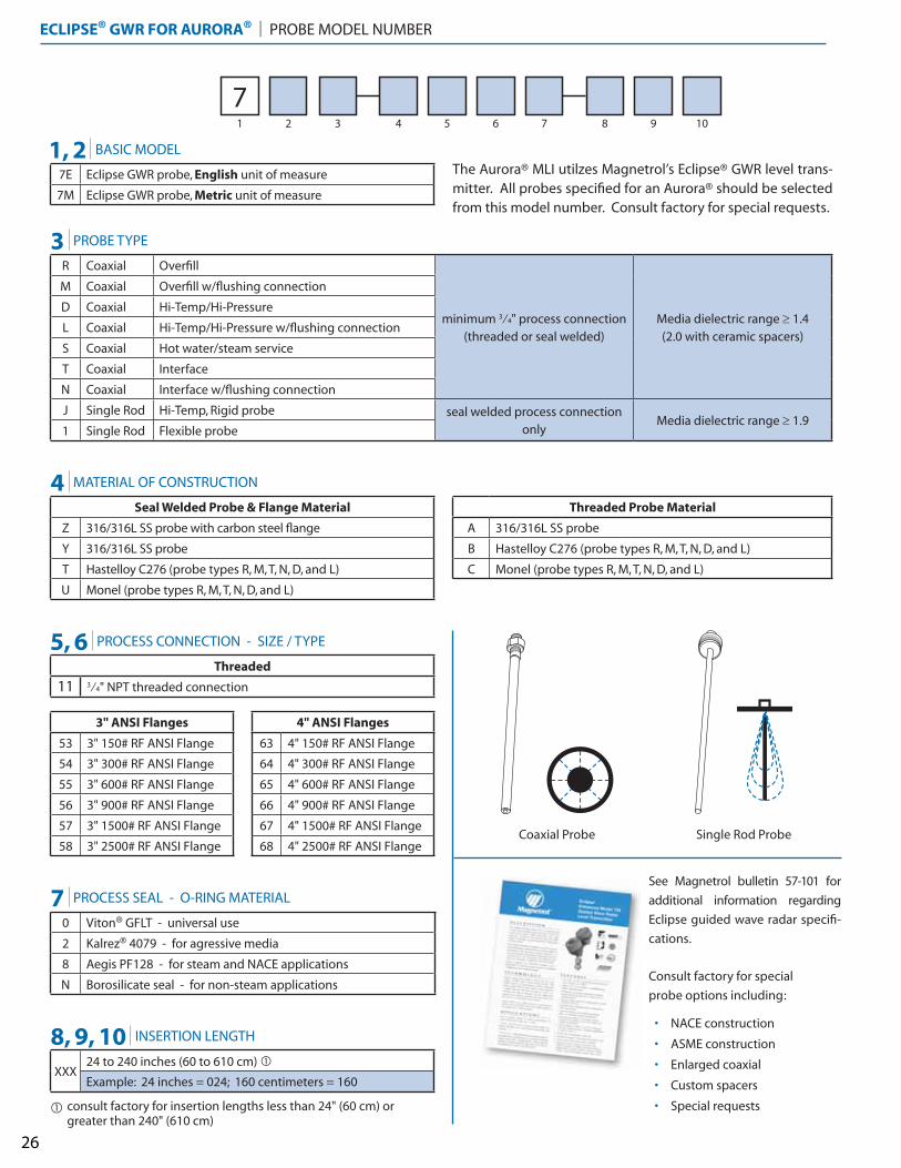
ECLIPSE® GWR FOR AURORA® | PROBE MODEL NUMBER
26
1 2 3 4 5 6 7 8 9 10
7
• NACE construction
• ASME construction
• Enlarged coaxial
• Custom spacers
• Special requests
7E Eclipse GWR probe, English unit of measure
7M Eclipse GWR probe, Metric unit of measure
R Coaxial Overfill
minimum 3⁄4" process connection (threaded or seal welded)
Media dielectric range � 1.4(2.0 with ceramic spacers)
M Coaxial Overfill w/flushing connection
D Coaxial Hi-Temp/Hi-Pressure
L Coaxial Hi-Temp/Hi-Pressure w/flushing connection
S Coaxial Hot water/steam service
T Coaxial Interface
N Coaxial Interface w/flushing connection
J Single Rod Hi-Temp, Rigid probe seal welded process connection only
Media dielectric range � 1.91 Single Rod Flexible probe
Seal Welded Probe & Flange Material
Z 316/316L SS probe with carbon steel flange
Y 316/316L SS probe
T Hastelloy C276 (probe types R, M, T, N, D, and L)
U Monel (probe types R, M, T, N, D, and L)
0 Viton® GFLT - universal use
2 Kalrez® 4079 - for agressive media
8 Aegis PF128 - for steam and NACE applications
N Borosilicate seal - for non-steam applications
Threaded
11 3⁄4" NPT threaded connection
1, 2
3
BASIC MODEL
PROBE TYPE
4
7
8, 9, 10
5, 6
MATERIAL OF CONSTRUCTION
PROCESS SEAL - O-RING MATERIAL
INSERTION LENGTH
PROCESS CONNECTION - SIZE / TYPE
XXX24 to 240 inches (60 to 610 cm) �
Example: 24 inches = 024; 160 centimeters = 160
consult factory for insertion lengths less than 24" (60 cm) or greater than 240" (610 cm)
�
4" ANSI Flanges
63 4" 150# RF ANSI Flange
64 4" 300# RF ANSI Flange
65 4" 600# RF ANSI Flange
66 4" 900# RF ANSI Flange
67 4" 1500# RF ANSI Flange
68 4" 2500# RF ANSI Flange
3" ANSI Flanges
53 3" 150# RF ANSI Flange
54 3" 300# RF ANSI Flange
55 3" 600# RF ANSI Flange
56 3" 900# RF ANSI Flange
57 3" 1500# RF ANSI Flange
58 3" 2500# RF ANSI Flange
The Aurora® MLI utilzes Magnetrol’s Eclipse® GWR level trans-mitter. All probes specified for an Aurora® should be selected from this model number. Consult factory for special requests.
Single Rod ProbeCoaxial Probe
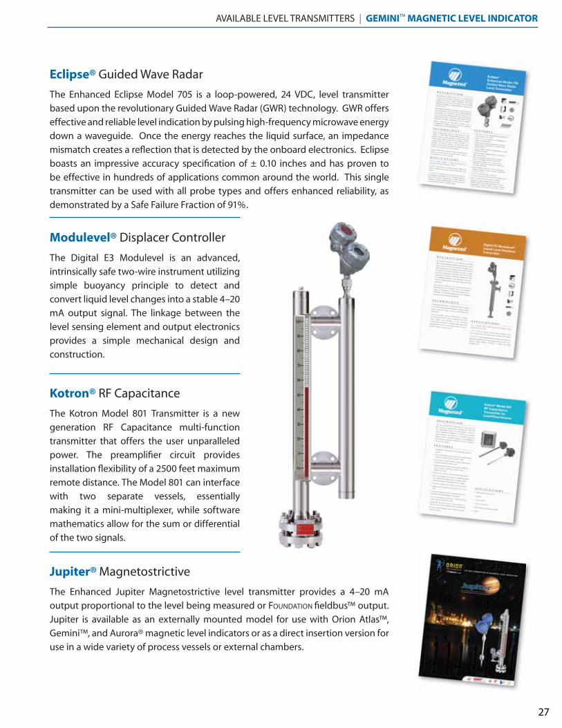
Eclipse® Guided Wave Radar
Modulevel® Displacer Controller
Kotron® RF Capacitance
Jupiter® Magnetostrictive
AVAILABLE LEVEL TRANSMITTERS | GEMINI™ MAGNETIC LEVEL INDICATOR
The Enhanced Eclipse Model 705 is a loop-powered, 24 VDC, level transmitter
based upon the revolutionary Guided Wave Radar (GWR) technology. GWR offers
effective and reliable level indication by pulsing high-frequency microwave energy
down a waveguide. Once the energy reaches the liquid surface, an impedance
mismatch creates a reflection that is detected by the onboard electronics. Eclipse
boasts an impressive accuracy specification of ± 0.10 inches and has proven to
be effective in hundreds of applications common around the world. This single
transmitter can be used with all probe types and offers enhanced reliability, as
demonstrated by a Safe Failure Fraction of 91%.
The Digital E3 Modulevel is an advanced,
intrinsically safe two-wire instrument utilizing
simple buoyancy principle to detect and
convert liquid level changes into a stable 4–20
mA output signal. The linkage between the
level sensing element and output electronics
provides a simple mechanical design and
construction.
The Kotron Model 801 Transmitter is a new
generation RF Capacitance multi-function
transmitter that offers the user unparalleled
power. The preamplifier circuit provides
installation flexibility of a 2500 feet maximum
remote distance. The Model 801 can interface
with two separate vessels, essentially
making it a mini-multiplexer, while software
mathematics allow for the sum or differential
of the two signals.
The Enhanced Jupiter Magnetostrictive level transmitter provides a 4–20 mA
output proportional to the level being measured or FOUNDATION fieldbus™ output.
Jupiter is available as an externally mounted model for use with Orion Atlas™,
Gemini™, and Aurora® magnetic level indicators or as a direct insertion version for
use in a wide variety of process vessels or external chambers.
27
28
1 2 3 4 5 6 7 8 9 10
012 13 14 1511
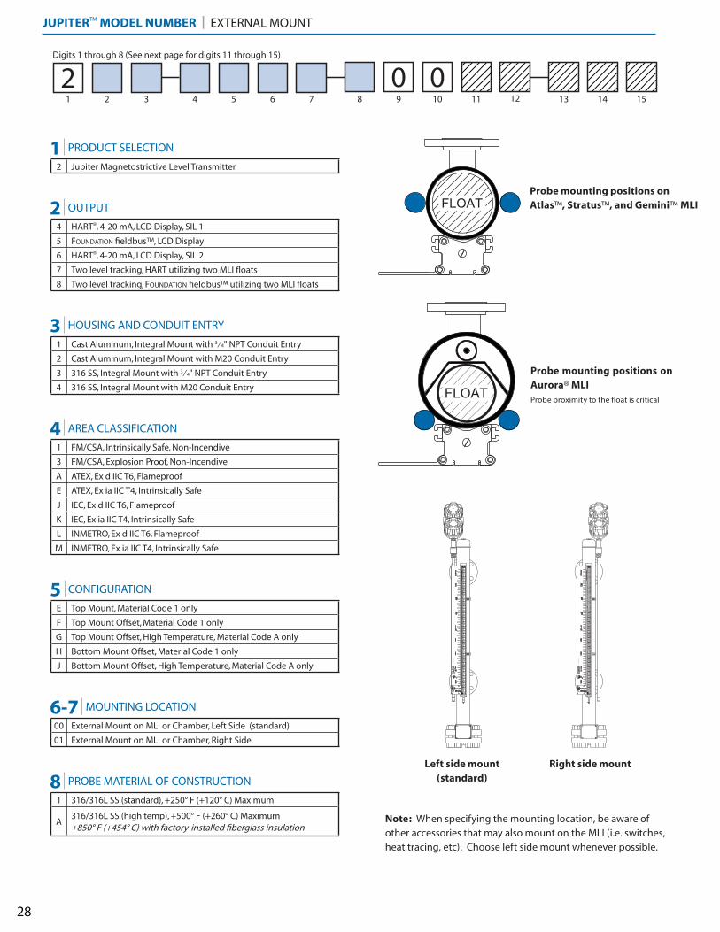
4 HART®, 4-20 mA, LCD Display, SIL 1
5 FOUNDATION fieldbus™, LCD Display
6 HART®, 4-20 mA, LCD Display, SIL 2
7 Two level tracking, HART utilizing two MLI floats
8 Two level tracking, FOUNDATION fieldbus™ utilizing two MLI floats
1 Cast Aluminum, Integral Mount with 3⁄4" NPT Conduit Entry
2 Cast Aluminum, Integral Mount with M20 Conduit Entry
3 316 SS, Integral Mount with 3⁄4" NPT Conduit Entry
4 316 SS, Integral Mount with M20 Conduit Entry
1 FM/CSA, Intrinsically Safe, Non-Incendive
3 FM/CSA, Explosion Proof, Non-Incendive
A ATEX, Ex d IIC T6, Flameproof
E ATEX, Ex ia IIC T4, Intrinsically Safe
J IEC, Ex d IIC T6, Flameproof
K IEC, Ex ia IIC T4, Intrinsically Safe
L INMETRO, Ex d IIC T6, Flameproof
M INMETRO, Ex ia IIC T4, Intrinsically Safe
E Top Mount, Material Code 1 only
F Top Mount Offset, Material Code 1 only
G Top Mount Offset, High Temperature, Material Code A only
H Bottom Mount Offset, Material Code 1 only
J Bottom Mount Offset, High Temperature, Material Code A only
00 External Mount on MLI or Chamber, Left Side (standard)
01 External Mount on MLI or Chamber, Right Side
1 316/316L SS (standard), +250° F (+120° C) Maximum
A316/316L SS (high temp), +500° F (+260° C) Maximum+850° F (+454° C) with factory-installed fiberglass insulation
02
2 Jupiter Magnetostrictive Level Transmitter
Note: When specifying the mounting location, be aware of other accessories that may also mount on the MLI (i.e. switches, heat tracing, etc). Choose left side mount whenever possible.
1 PRODUCT SELECTION
2 OUTPUT
3 HOUSING AND CONDUIT ENTRY
4 AREA CLASSIFICATION
5 CONFIGURATION
6-7 MOUNTING LOCATION
8 PROBE MATERIAL OF CONSTRUCTION
JUPITER™ MODEL NUMBER | EXTERNAL MOUNT
FLOAT
INS
TR
UM
EN
TS
I N S T R U M E N T S
INS
TR
UM
EN
TS
I N S T R U M E N T S
Digits 1 through 8 (See next page for digits 11 through 15)
Left side mount(standard)
Right side mount
Probe mounting positions on Aurora® MLIProbe proximity to the float is critical
Probe mounting positions on Atlas™, Stratus™, and Gemini™ MLI
29
1 2 3 4 5 6 7 8 9 10
012 13 14 1511
0
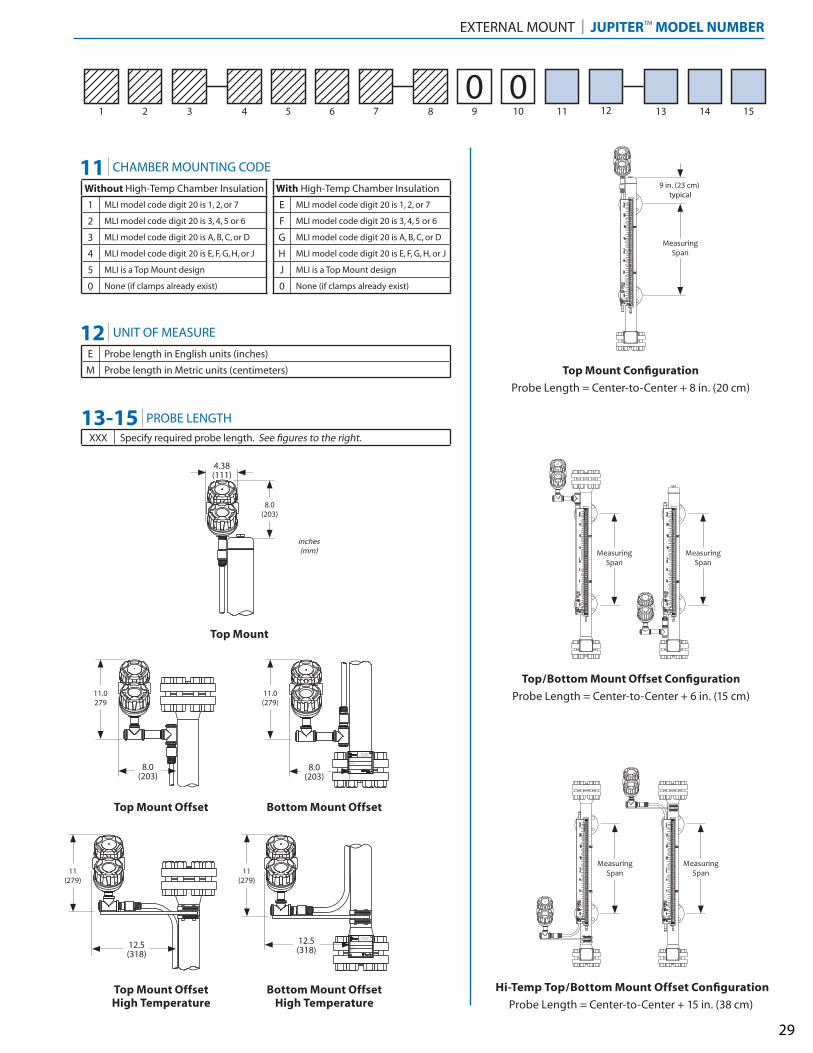
EXTERNAL MOUNT | JUPITER™ MODEL NUMBER
Without High-Temp Chamber Insulation
1 MLI model code digit 20 is 1, 2, or 7
2 MLI model code digit 20 is 3, 4, 5 or 6
3 MLI model code digit 20 is A, B, C, or D
4 MLI model code digit 20 is E, F, G, H, or J
5 MLI is a Top Mount design
0 None (if clamps already exist)
E Probe length in English units (inches)
M Probe length in Metric units (centimeters)
XXX Specify required probe length. See figures to the right.
11 CHAMBER MOUNTING CODE
With High-Temp Chamber Insulation
E MLI model code digit 20 is 1, 2, or 7
F MLI model code digit 20 is 3, 4, 5 or 6
G MLI model code digit 20 is A, B, C, or D
H MLI model code digit 20 is E, F, G, H, or J
J MLI is a Top Mount design
0 None (if clamps already exist)
12 UNIT OF MEASURE
13-15 PROBE LENGTH
SPECIFIC GRAVITY:
TAG NO.:
BATON ROUGE, LAPHONE 1-225-906-2343
FAX 1-225-906-2344WWW.ORIONINSTRUMENTS.COMI N S T R U M E N T S
MAX. PRESSURE:
MAX. TEMPERATURE:
MODEL NO.:
SERIAL NO.:
MADE IN USA
SPECIFIC GRAVITY:
TAG NO.:
BATON ROUGE, LAPHONE 1-225-906-2343
FAX 1-225-906-2344WWW.ORIONINSTRUMENTS.COMI N S T R U M E N T S
MAX. PRESSURE:
MAX. TEMPERATURE:
MODEL NO.:
SERIAL NO.:
MADE IN USA
Top Mount
Top Mount Offset Bottom Mount Offset
Top Mount OffsetHigh Temperature
Bottom Mount OffsetHigh Temperature
8.0(203)
4.38(111)
inches(mm)
8.0(203)
12.5(318)
11.0279
8.0(203)
11.0(279)
12.5(318)
11(279)
11(279)
INS
TR
UM
EN
T S
I N S T R U M E N T S I N S T R U M E N T S
INS
TR
UM
EN
T S
MeasuringSpan
MeasuringSpan
I N S T R U M E N TS
INS
TR
UM
EN
T S
I N S T R U M E N TS
INS
TR
UM
EN
T S
MeasuringSpan
MeasuringSpan
INS
TR
UM
EN
T S
I N S T R U M E N TS
MeasuringSpan
9 in. (23 cm) typical
Top Mount Configuration
Probe Length = Center-to-Center + 8 in. (20 cm)
Top/Bottom Mount Offset Configuration
Probe Length = Center-to-Center + 6 in. (15 cm)
Hi-Temp Top/Bottom Mount Offset Configuration
Probe Length = Center-to-Center + 15 in. (38 cm)
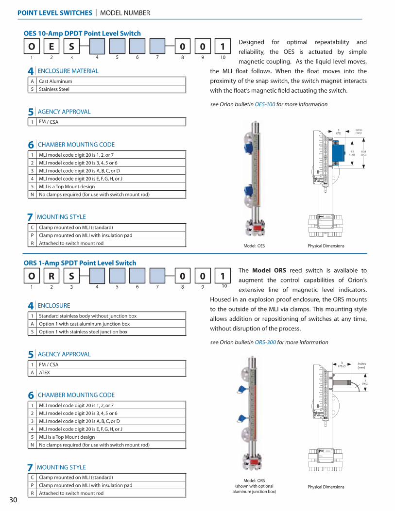
The Model ORS reed switch is available to
augment the control capabilities of Orion’s
extensive line of magnetic level indicators.
Housed in an explosion proof enclosure, the ORS mounts
to the outside of the MLI via clamps. This mounting style
allows addition or repositioning of switches at any time,
without disruption of the process.
see Orion bulletin ORS-300 for more information
Designed for optimal repeatability and
reliability, the OES is actuated by simple
magnetic coupling. As the liquid level moves,
the MLI float follows. When the float moves into the
proximity of the snap switch, the switch magnet interacts
with the float’s magnetic field actuating the switch.
see Orion bulletin OES-100 for more information
OES 10-Amp DPDT Point Level Switch
1 2 3 4 5 6 7
O8 9 10
00E S 1
ORS 1-Amp SPDT Point Level Switch
1 2 3 4 5 6 7
O8 9 10
00R S 1
I N S T R U M E N T S
BATON ROUGE, LAPHONE 1-225-906-2343
FAX 1-225-906-2344WWW.ORIONINSTRUMENTS.COM
MAX. PRESSURE:
MAX. TEMPERATURE:
TAG NO.:
MODEL NO.:
SERIAL NO.:
I N S T R U M E N T S
MADE IN USA
I N S T R U M E N T S
BATON ROUGE, LAPHONE 1-225-906-2343
FAX 1-225-906-2344WWW.ORIONINSTRUMENTS.COM
MAX. PRESSURE:
MAX. TEMPERATURE:
TAG NO.:
MODEL NO.:
SERIAL NO.:
I N S T R U M E N T S
MADE IN USA
POINT LEVEL SWITCHES | MODEL NUMBER
30
5.5(139)
3(76)
����������
8.38(212)
3(76.2)
����������
3(76.2)
A Cast Aluminum
S Stainless Steel
1 FM / CSA
4 ENCLOSURE MATERIAL
5 AGENCY APPROVAL
1 MLI model code digit 20 is 1, 2, or 7
2 MLI model code digit 20 is 3, 4, 5 or 6
3 MLI model code digit 20 is A, B, C, or D
4 MLI model code digit 20 is E, F, G, H, or J
5 MLI is a Top Mount design
N No clamps required (for use with switch mount rod)
6 CHAMBER MOUNTING CODE
C Clamp mounted on MLI (standard)
P Clamp mounted on MLI with insulation pad
R Attached to switch mount rod
7 MOUNTING STYLE
1 Standard stainless body without junction box
A Option 1 with cast aluminum junction box
S Option 1 with stainless steel junction box
1 FM / CSA
A ATEX
4 ENCLOSURE
5 AGENCY APPROVAL
1 MLI model code digit 20 is 1, 2, or 7
2 MLI model code digit 20 is 3, 4, 5 or 6
3 MLI model code digit 20 is A, B, C, or D
4 MLI model code digit 20 is E, F, G, H, or J
5 MLI is a Top Mount design
N No clamps required (for use with switch mount rod)
6 CHAMBER MOUNTING CODE
C Clamp mounted on MLI (standard)
P Clamp mounted on MLI with insulation pad
R Attached to switch mount rod
7 MOUNTING STYLE
Model: ORS(shown with optional
aluminum junction box)
Model: OES
Physical Dimensions
Physical Dimensions
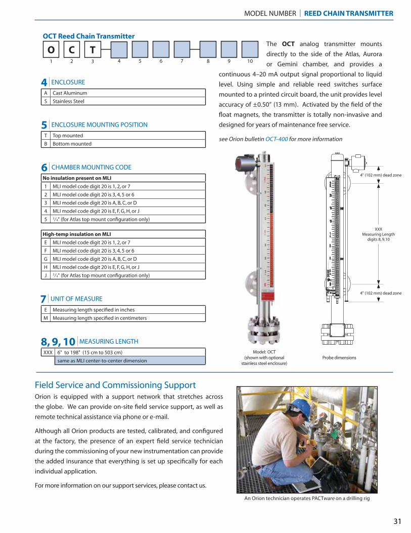
The OCT analog transmitter mounts
directly to the side of the Atlas, Aurora
or Gemini chamber, and provides a
continuous 4–20 mA output signal proportional to liquid
level. Using simple and reliable reed switches surface
mounted to a printed circuit board, the unit provides level
accuracy of ±0.50” (13 mm). Activated by the field of the
float magnets, the transmitter is totally non-invasive and
designed for years of maintenance free service.
see Orion bulletin OCT-400 for more information
OCT Reed Chain Transmitter
1 2 3 4 5 6 7
O8 9 10
C T
INS
TR
UM
EN
TS
I N S T R U M E N T S
MODEL NUMBER | REED CHAIN TRANSMITTER
31
4" (102 mm) dead zone
XXXMeasuring Length
digits 8, 9,10
Field Service and Commissioning Support
A Cast Aluminum
S Stainless Steel
T Top mounted
B Bottom mounted
4 ENCLOSURE
5 ENCLOSURE MOUNTING POSITION
No insulation present on MLI
1 MLI model code digit 20 is 1, 2, or 7
2 MLI model code digit 20 is 3, 4, 5 or 6
3 MLI model code digit 20 is A, B, C, or D
4 MLI model code digit 20 is E, F, G, H, or J
5 3⁄4" (for Atlas top mount configuration only)
6 CHAMBER MOUNTING CODE
E Measuring length specified in inches
M Measuring length specified in centimeters
7 UNIT OF MEASURE
High-temp insulation on MLI
E MLI model code digit 20 is 1, 2, or 7
F MLI model code digit 20 is 3, 4, 5 or 6
G MLI model code digit 20 is A, B, C, or D
H MLI model code digit 20 is E, F, G, H, or J
J 3⁄4" (for Atlas top mount configuration only)
XXX 6" to 198" (15 cm to 503 cm)
same as MLI center-to-center dimension
8, 9, 10 MEASURING LENGTH
An Orion technician operates PACTware on a drilling rig
Orion is equipped with a support network that stretches across
the globe. We can provide on-site field service support, as well as
remote technical assistance via phone or e-mail.
Although all Orion products are tested, calibrated, and configured
at the factory, the presence of an expert field service technician
during the commissioning of your new instrumentation can provide
the added insurance that everything is set up specifically for each
individual application.
For more information on our support services, please contact us.
4" (102 mm) dead zone
Model: OCT(shown with optional
stainless steel enclosure)Probe dimensions

2105 Oak Villa Boulevard • Baton Rouge, Louisiana 70815 • 225-906-2343 • Toll Free 866-55-ORION (866-556-7466) • Fax 225-906-2344 • www.orioninstruments.com
Copyright © 2011 Orion Instruments, LLC. All rights reserved. Printed in the USA.Performance specifications are effective with date of issue and are subject to change without notice.
Orion, Orion logotype, Magnetrol, Magnetrol logotype, Aurora, Jupiter, Eclipse, Modulevel, and Kotron are registered trademarks of Magnetrol International.
Atlas, Gemini, Stratus, and Insta-Seal are trademarks of Magnetrol International.
HART® is a registered trademark of the HART Communication Foundation.
FOUNDATION fieldbus™ is a trademark of Fieldbus Foundation.
Hastelloy® is a registered trademark of Haynes International.
Monel® is a registered trademark of the INCO family of companies.
Teflon® is a registered trademark of DuPont.
Halar® is a registered trademark of Solvay Solexis S.p.A.
Tri-Clamp® is a registered trademark of Ladish Company.
BULLETIN: ORI-138.2
EFFECTIVE: January 2011
Orion maintains competitive lead times for all of our products. If expedited shipping is required,
we can accomodate your request.
To improve delivery on your order, contact your local Orion Instruments representative or
contact us directly.
E X P E D I T E D S H I P P I N G AVA I L A B L E