Embed Size (px)
Citation preview

ORNL/TM-2012/78
Magnetic Field Processing – A Heat Free Heat Treating Method
August 8, 2012
Prepared by Gerard (Gerry) M. Ludtka Distinguished R&D Staff
DOCUMENT AVAILABILITY
Reports produced after January 1, 1996, are generally available free via the U.S. Department of Energy (DOE) Information Bridge. Web site http://www.osti.gov/bridge Reports produced before January 1, 1996, may be purchased by members of the public from the following source. National Technical Information Service 5285 Port Royal Road Springfield, VA 22161 Telephone 703-605-6000 (1-800-553-6847) TDD 703-487-4639 Fax 703-605-6900 E-mail [email protected] Web site http://www.ntis.gov/support/ordernowabout.htm Reports are available to DOE employees, DOE contractors, Energy Technology Data Exchange (ETDE) representatives, and International Nuclear Information System (INIS) representatives from the following source. Office of Scientific and Technical Information P.O. Box 62 Oak Ridge, TN 37831 Telephone 865-576-8401 Fax 865-576-5728 E-mail [email protected] Web site http://www.osti.gov/contact.html
This report was prepared as an account of work sponsored by an agency of the United States Government. Neither the United States Government nor any agency thereof, nor any of their employees, makes any warranty, express or implied, or assumes any legal liability or responsibility for the accuracy, completeness, or usefulness of any information, apparatus, product, or process disclosed, or represents that its use would not infringe privately owned rights. Reference herein to any specific commercial product, process, or service by trade name, trademark, manufacturer, or otherwise, does not necessarily constitute or imply its endorsement, recommendation, or favoring by the United States Government or any agency thereof. The views and opinions of authors expressed herein do not necessarily state or reflect those of the United States Government or any agency thereof.

Acknowledgements
This research utilized ORNL’s unique and world-class Thermomagnetic Processing Facilities
supported by the Office of Energy Efficiency and Renewable Energy, U.S. Department of Energy.
Research supported by ORNL’s Shared Research Equipment (SHaRE) User Facility, which is
sponsored by the Office of Basic Energy Sciences, U.S. Department of Energy. The authors also wish
to thank Drs. Thomas Muth and Ryan Dehoff for providing their technical review of this report.

ORNL/TM-2012/78
DOE EERE Advanced Manufacturing Office (Formerly Industrial Technologies Program)
CPS Agreement No. 17875
June 30, 2008 to September 30, 2011
FINAL TECHNICAL REPORT:
Magnetic Field Processing – A Heat Free Heat Treating Method
Authors
Gerard (Gerry) M. Ludtka
(865-574-5098, [email protected])
Gail Mackiewicz Ludtka
John B. Wilgen
Edward A. Kenik
Chad M. Parish
Orlando Rios
J. Hiram Rogers
Michelle Manuel (University of Florida)
Roger A. Kisner
Thomas R. Watkins
Bart L. Murphy
Date Published: August, 2012
Prepared by
OAK RIDGE NATIONAL LABORATORY
Oak Ridge, Tennessee 37831-6283
managed by
UT-BATTELLE, LLC
for the
U.S. DEPARTMENT OF ENERGY
under contract DE-AC05-00OR22725

Table of Contents LIST OF FIGURES ............................................................................................................................. vii LIST OF TABLES ................................................................................................................................ xi LIST OF ACRONYMS ...................................................................................................................... xiii EXECUTIVE SUMMARY ................................................................................................................... 1 1. INTRODUCTION ......................................................................................................................... 3
1.1 Description of the Technology ............................................................................................... 3 1.2 Focus Areas ............................................................................................................................ 3 1.3 Broad Potential Applications, Energy Savings, Environmental and Economic Benefits ...... 4 1.4 Commercialization Status ...................................................................................................... 5
2. TECHNOLOGY BACKGROUND .................................................................................................. 7 2.1 High- and Thermomagnetic Processing (HTMP) Technology .............................................. 7 2.2 Electromagnetic Acoustical Transducer (EMAT) Technology ............................................. 8 2.3 Qualifications and Relevant Expertise of Project Team ...................................................... 10
3. RESULTS AND DISCUSSION ..................................................................................................... 11 3.1 Heat- And Cryo-Free, Retained Austenite Conversion ........................................................ 12
3.1.1 Material Characterization ................................................................................................ 16 3.2 Superior Strength and Ductility in Steels Via HTMP .......................................................... 18
3.2.1 High Strength Bainitic Alloy ........................................................................................... 18 3.3 IMPROVED CASTING HOMOGENEITY AND PROPERTIES VIA EMAT ..................... 29
3.3.1 Cast Iron .......................................................................................................................... 30 3.3.2 Magnesium with Dysprosia (Dy2O3) Nanoparticle Dispersion EMAT Evaluation ........ 36 3.3.3 EMAT Technology for Developing Wrought Properties in Additional Mg As-cast Alloys
..................................................................................................................................................... 41 3.4 FACILITATION OF HTMP/EMAT TECHNOLOGY COMMERCIALIZATION ........... 45 3.4.1 Magnet Design Considerations ........................................................................................ 45 3.4.2 Commercial Prototype System Designed, Fabricated, Installed, and Operational at ORNL 51
4. CONCLUSIONS AND RECCOMENDATIONS ....................................................................... 59 5. REFERENCES ............................................................................................................................ 61
vii
LIST OF FIGURES
Figure 1. The HTMP innovation will enable major energy savings and material performance
breakthroughs for the myriad of markets and applications. ................................................................... 4 Figure 2. The shift (blues lines) in the phase boundaries (solvus lines) for a 52100 steel under the
influence of a 9 Tesla magnetic field as predicted using ThermoCalc after this software was modified
to factor in the magnetic free energy term. ............................................................................................. 8 Figure 3. Induction heating in a high-field magnet, showing the applied H-field of the induction coil,
the induced surface current in the sample (J), the static field of the magnet (B), and the resulting JxB
force. ....................................................................................................................................................... 9 Figure 4. Schematic of the original ASR process showing the various processing conditions and
subsequent microstructural constituent volume fractions at each stage. .............................................. 13 Figure 5. Caterpillar’s application for the RA conversion thrust of this project was their fuel injector
tip advanced design thrust. ................................................................................................................... 13 Figure 6. Several induction coil designs that were used in initial experiments to develop uniform
temperatures across the entire face of the safety razor strip. ................................................................ 14 Figure 7. A novel spring holding design was employed to keep the razor strip in tension while
applying the HTMP process for the thermal transient shown in Fig. 4. ............................................... 14 Figure 8. A quartz environmental tube was employed to surround the razor strip so an inert gas could
be blown across the sample while at elevated temperature to prevent oxidation. ................................ 15 Figure 9. An example of the heating uniformity using an elliptical-turn induction coil for the razor
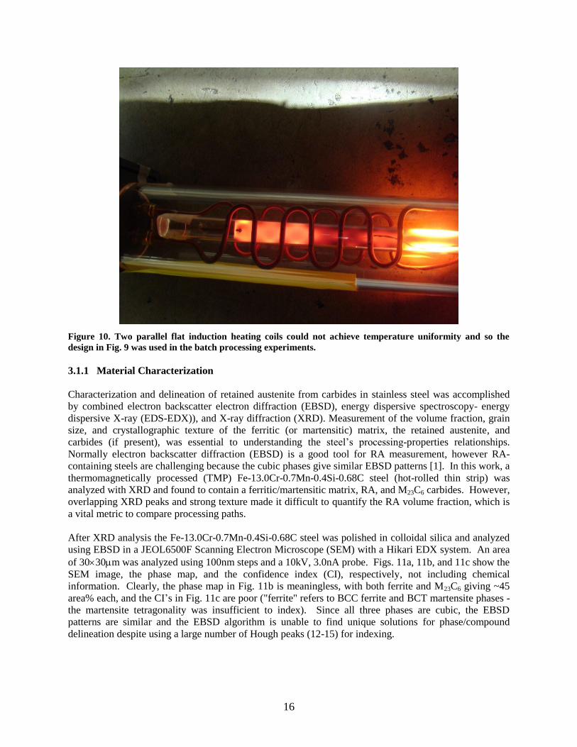
strip. ...................................................................................................................................................... 15 Figure 10. Two parallel flat induction heating coils could not achieve temperature uniformity and so
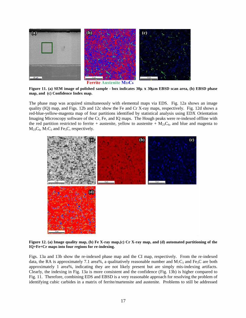
the design in Fig. 9 was used in the batch processing experiments. ..................................................... 16 Figure 11. (a) SEM image of polished sample -
phase map not including chemical information, and (c) Confidence Index map not including
chemical information. ........................................................................................................................... 17 Figure 12. (a) Image quality map, (b) Fe X-ray map,(c) Cr X-ray map, and (d) automated partitioning
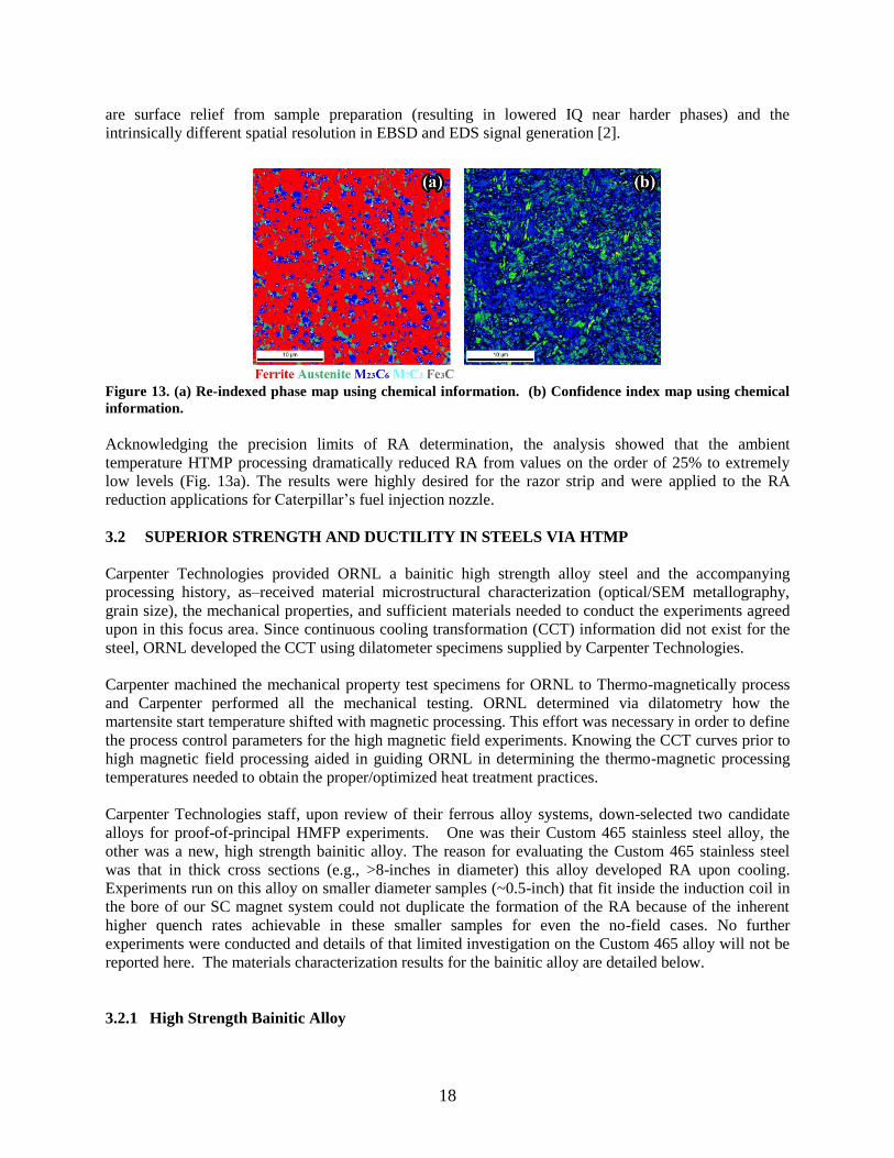
of the IQ+Fe+Cr maps into four regions for re-indexing. .................................................................... 17 Figure 13. (a) Re-indexed phase map using chemical information. (b) Confidence index map using
chemical information. ........................................................................................................................... 18 Figure 14. Plot depicting the experimentally determined martensite start (Ms) phase transition
temperature (238˚C) for a baseline steel composition using high speed quenching dilatometry
techniques during high speed helium gas quenching (>200˚C/s) from the austenite single phase field.
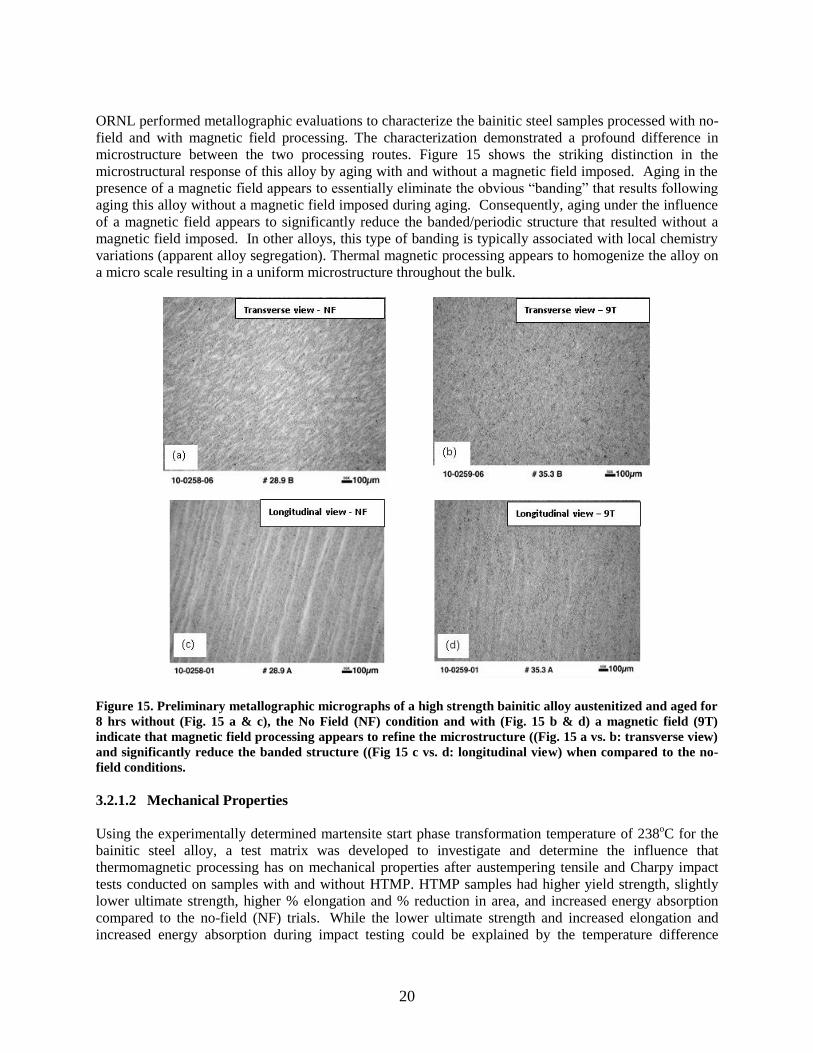
.............................................................................................................................................................. 19 Figure 15. Preliminary metallographic micrographs of a high strength bainitic alloy austenitized and
aged for 8 hrs without (Fig. 15 a & c), the No Field (NF) condition and with (Fig. 15 b & d) a
magnetic field (9T) indicate that magnetic field processing appears to refine the microstructure ((Fig.
15 a vs. b: transverse view) and significantly reduce the banded structure ((Fig 15 c vs. d: longitudinal
view) when compared to the no-field conditions. ................................................................................ 20 Figure 16. Charpy V-notch property results for this high strength bainitic alloy out-perform maraging
250 steel. ............................................................................................................................................... 22 Figure 17. Scanning Electron Microscopy (SEM) micrographs of the NF (no-field) longitudinal
section exhibiting very fine microstructural features (possibly a fine carbide dispersion) for a region
that appears bright in the SEM (opposite to perspective in optical micrographs). ............................... 23 Figure 18. Scanning Electron Microscopy (SEM) micrographs of the alternating contrast region to
Figure17 for the NF (no-field) longitudinal section exhibits very fine microstructural features
(possibly a fine carbide dispersion) for a region that appears bright in the SEM (opposite to
perspective in optical micrographs). ..................................................................................................... 24 Figure 19. Scanning Electron Microscopy (SEM) micrographs of the alternating contrast regions in
viii
the 9T longitudinal section exhibits very fine microstructural features for the bright region that
contrasts with a mixture of fine and coarse in the darker regions that were visible in the optical
micrographs.......................................................................................................................................... 24 Figure 20. EBSD analyses determination of the grain size distribution in the longitudinal direction for
the NF case. .......................................................................................................................................... 25 Figure 21. EBSD analyses determination of the grain size distribution in the longitudinal direction for
the 9 T TMP case. ................................................................................................................................ 26 Figure 22. Scanning transmission BF and HAADF micrographs reveal a dual population of fine
carbides in the TMP sample consisting of elongated carbides and very fine and copious spherical
carbides. ............................................................................................................................................... 27 Figure 23. Elemental spectra obtained in the SEM for the light versus dark contrast regions in the
non-TMP sample ID 28.9A (These data were further processed in Fig. 24.) ...................................... 27 Figure 24. The elemental spectra data shown in Fig. 23 were analyzed to show the local chemistry
differences of the various elements which indicates that the dark areas appear to be enriched in Si, V,
Cr, and Ni. ............................................................................................................................................ 28 Figure 25. Microstructural evaluation of the fine microstructure in thermomagnetically processed
Carpenter bainitic alloy has discovered a very fine and copious nano-carbide cluster dispersion
throughout the microstructure that does not appear in non-thermomagnetically processed samples. . 29 Figure 26. Thermodynamic software calculation predicting phase stabilities and weight fraction of
each phase for the GMC010 alloy as a function of temperature to define optimum EMAT processing
conditions in the mushy, two-phase liquid plus solid field. ................................................................. 30 Figure 27. Experimental setup for inducing radial pulsating forces using a combination of a large
axial magnetic field and induction coil to produce the EMAT effect. ................................................. 31 Figure 28. The EMAT processing dramatically altered the appearance of the final solidified
microstructures in the cast iron samples as well as significantly improved the hardness of the casting.
............................................................................................................................................................. 32 Figure 29. BSE images of cast iron as-received and processed under 0, 4.5 and 18 tesla fields,
respectively. ......................................................................................................................................... 33 Figure 30. (a) Higher magnification BSE image of cast iron re-cast under 18 tesla field. ................. 33 Figure 31. Different carbide types (1 and 2) and morphologies (I and II) were observed in the various
conditions processed in these EMAT experiments. ............................................................................. 34 Figure 32. . The elongated Carbide 2 phase (darker elongated phase shown in the TEM Bright Field
image on left) is shown to be face-centered cubic from these multiple zone axis electron diffraction
patterns. ................................................................................................................................................ 35 Figure 33. The complex nature of the microstructure that evolved in the cast iron during the 18 T
EMATsolidification experiment is clearly evident (in the TEM bright field image to the left) by the
multiple phases (indicated as M [matrix], G, H, I, J, K) clustered in this small region. ...................... 35 Figure 34. Schematic representing the experimental set-up for EMAT processing of pure Mg with
nanoparticles incorporated into the set-up to achieve nano-particle dispersion. .................................. 37 Figure 35. Photo of the Mg sample stainless steel crucible after thermo-magnetic processing. .......... 37 Figure 36. A pure Mg samples is shown initially in the stainless steel crucible it was prepared in prior
tothe EMAT experiments with (a) showing the sample prior to placement of the loose nanoparticles in
the assembly and (b) showing the final assembly with a containment lid on top of the crucible in the
quartz, inert atmosphere experiment tube. ........................................................................................... 38 Figure 37. Transmission electron microscopy micrographs of the uniformly dispersed dysprosium
oxide. .................................................................................................................................................... 38 Figure 38. BF (middle two images) and DF (two right hand side images) images of one location of
the EMAT processed Mg ingot clearly showing the uniformly distributed dysprosia nanoparticles
achieved in this experiment. ................................................................................................................ 39 Figure 39. A second location in this cross section showed more evidence of the finely dispersed
Dysprosia nanoparticles. ...................................................................................................................... 39

ix
Figure 40. Energy Dispersive X-ray Spectroscopy (EDS) characterization clearly identified these
agglomerated nanoparticles as dysprosia. ............................................................................................ 40 Figure 41. The HAADF (high angle annular dark field) STEM technique (which is atomic number,
Z,sensitive) clearly shows the contrast between the lower Z Mg matrix material and the higher Z-
based Dysprosia nanoparticles. ............................................................................................................ 40 Figure 42. One series of EMAT experiments stopped the EMAT effect by turning off the induction
power. ................................................................................................................................................... 43 Figure 43. The second series of EMAT experiments continued the EMAT at a reduced induction
power supply setting until solidification was completed. ..................................................................... 43 Figure 44. The recent EMAT experiments defined in Tables 10 and 11 after being EDM cut in half. 44 Figure 45. A typical example of a Mg ingot after it had been EMAT processed and EDM cut in half.
.............................................................................................................................................................. 44 Figure 46. Top view and cross-section view of a single-layer helically wound induction heating coil
showing the axial alignment of the 9 Tesla magnetic (B) field. ........................................................... 47 Figure 47. Total radial strain as a function of frequency for a 2.75" diameter coil, with 2000 amp
peak coil current (1410 A(rms)), and a 9T magnetic field ................................................................... 49 Figure 48. Resonant magnification as a function of frequency for various normalized damping factors.
.............................................................................................................................................................. 50 Figure 49. Image of the induction coil extracted from a design drawing of the induction insert for the
8" vertical magnet. ................................................................................................................................ 51 Figure 50. The inner main coil of the new commercial prototype 9-T, 8-inch diameter warm bore
superconducting magnet system was fabricated and tested by American Magnetics, Inc. in Oak Ridge,
TN. ........................................................................................................................................................ 52 Figure 51. Views (a), (b), & (c) show the vessel for the 8-inch diameter warm-bore, 9-T
superconducting magnet system containing (d) the main superconducting solenoid coil with the
quenching resistors exposed. ................................................................................................................ 53 Figure 52. Photos (a) & (b) show the delivery and placement of the commercial scale frame that will
beintegrated with ORNL’s 8-inch diameter bore, 9T superconducting magnet, shown here in (c) an
artist’s rendition (d) completed magnet. ............................................................................................... 54 Figure 53. The world’s first commercial prototype TMP/EMAT processing system is operational now
at ORNL and has been used for experimental trials on industrial-scale components. ......................... 55 Figure 54. The ORNL commercial prototype HTMP/EMAT system with working platform installed.
.............................................................................................................................................................. 56 Figure 55. ORNL’s multiple HTMP/EMAT systems represent the world’s most advanced systems for
conducting high magnetic field experiments from small prototype to large scale commercial samples.
.............................................................................................................................................................. 57

xi
LIST OF TABLES
Table 1. Projected (by 2025) annual energy savings, CO2 reduction, and cost savings of HMFP
applications. ............................................................................................................................................ 5 Table 2. Chemistry of super bainitic alloy (Heat 010964) .................................................................. 19 Table 3. Mechanical property results for this high strength bainitic alloy demonstrate that HTMP
processing produces unprecedented, and simultaneous improvements in both yield strength and
ductility. ................................................................................................................................................ 21 Table 4 SEM-EDS characterization of the composition of the various phases present in the 18-T
EMAT processed sample ...................................................................................................................... 34 Table 5. SEM/BSE quantitative determination of phase volume fractions for several experimental
conditions. ............................................................................................................................................ 34 Table 6. Results of TEM analysis for W-modified cast iron ............................................................... 36 Table 7. Definition of Mg EMAT experiment sample identification and goal. ................................... 41 Table 8. Summary of Mg EMAT experiment control parameters for each condition. ......................... 42

LIST OF ACRONYMS
AMO Advanced Manufacturing Office
AMI American Magnetics Inc.
ASR American Safety Razor
ATM Ajax-Tocco Magnethermic B Magnetic Flux Density
BCC Body Centered Cubic
BCT Body Centered Tetragonal
BF Bright Field
BSE Backscattered Electron
BTU British Thermal Unit
CC Cubic Centimeter
CCT Continuous Cooling Transformation
CI Confidence Interval
DOE Department Of Energy
EBSD Electron Backscatter Diffraction
EDM Electro Discharge Machining
EDS Electron Dispersion Spectroscopy
EIP Energy Intensive Processes
EERE Office of Energy Efficiency and Renewable Energy
EMAT Electro-magnetic Acoustic Transducer
EMPA-WDS Electron Microprobe Analysis-Wavelength Dispersive Spectroscopy
FCC Face Centered Cubic
FIB Focused Ion Beam
FOLZ First Order Laue Zone
GHG Greenhouse Gasses
GM Gram
GPA Gigapascal
GPM Gallons per Minute
GPRA Government Performance and Results Act
H Magnetic Intensity
HAADF High Angle Annular Dark Field
HMFP High Magnetic Field Processing
HTMP High and Thermal Magnetic Processing
ID Inner Diameter
IPF Inverse Pole Figure
ITP Industrial Technologies Program
IQ Image Quality
J Surface Current
KHz Kilohertz
kW Kilowatt
M Magnetization
MM Million metric tonnes
n.d. Not Detected
NDI Nodular Ductile Iron
NF No Field
NHMFL National High Magnetic Field Laboratory
OD Outer Diameter
ORNL Oak Ridge National Laboratory
PSI Pounds per Square Inch

Q&T Quench and Temper
QUAD Quadrillion (1 Quad =1015
) Btus
RA Retained Austenite
SC Superconducting
SEM Scanning Electron Microscope
STEM Scanning Transmission Electron Microscope
T Temperature
T Tesla
TEM Transmission Electron Microscope
UTS Ultimate Tensile Strength
VHN Vickers Hardness Number
XRD X-Ray Diffraction
YS Yield Strength

1
EXECUTIVE SUMMARY
The High and Thermal Magnetic Processing/Electro-magnetic Acoustic Transducer (HTMP/EMAT)
technology has been shown to be an enabling disruptive materials processing technology, that can
achieve significant improvements in microstructure and consequently material performance beyond
that achievable through conventional processing, and will lead to the next generation of advanced
performance structural and functional materials.
HTMP exposure increased the reaction kinetics enabling refinement of microstructural features such
as finer martensite lath size, and finer, more copious, homogeneous dispersions of strengthening
carbides leading to combined strength and toughness improvements in bainitic steels.
When induction heating is applied in a high magnetic field environment, the induction heating coil is
configured so that high intensity acoustic/ultrasonic treatment occurs naturally. The configuration
results in a highly effective electromagnetic acoustical transducer (EMAT). HTMP combined with
applying high-field EMAT, produce a non-contact ultrasonic treatment that can be used to process
metal alloys in either the liquid state resulting in significant microstructural changes over
conventional processing. Proof-of-principle experiments on cast irons resulted in homogeneous
microstructures in small castings along with improved casting surface appearance. The experiment
showed that by exposing liquid metal to the non-contact acoustic/ultrasonic processing technology
developed using HMFP/EMAT wrought-like microstructures were developed in cast components.
This Energy Intensive Processes (EIP) project sponsored by the DOE EERE Advanced
Manufacturing Office (AMO) demonstrated the following:
The reduction of retained austenite in high carbon/high alloy steels with an ambient
temperature HTMP process, replacing either a cryogenic or double tempering thermal process
normally employed to accomplish retained austenite transformation. HTMP can be described
as a “heat-free”, heat treating technology. Lower residual stresses in HTMP treated materials
are anticipated since no thermal strains are involved in inducing the transformation of
retained austenite to martensite in high alloy steel.
The simultaneous increase of 12% in yield strength and 22% in impact energy in a bainitic
alloy using HTMP processing. This is a major breakthrough in materials processing for the
next generation of structural materials since conventionally processed materials show a
reduction in impact toughness with an increase in yield strength. HTMP is a new paradigm to
beneficially increase both yield strength and impact energy absorption simultaneously.
HTMP processing refined both the martensite lath population and the carbide dispersion in a
bainitic steel alloy during GausstemperingTM,1
. The refinement was believed to be responsible
for the simultaneous increase in strength and toughness. Hence, HTMP significantly impacts
nucleation and growth phenomenon.
HTMP processing developed comparable ultimate tensile strength and twice the impact
energy in a lower cost, lower alloy content (~8% alloy content) steel, compared to highly
alloyed, (31% alloy elements involving Ni, Co, and Mo) 250-grade margining steel. Future
low-cost HTMP alloys appear viable that will exceed the structural performance of highly
alloyed materials that are conventionally processed. This economic benefit will enable U.S.
industry to reduce cost (better more competitive worldwide) while maintaining or exceeding
current performance.
1 Gausstemper
TM is an ORNL trademark for the process of magnetically processing a material in a magnetic
field.
2
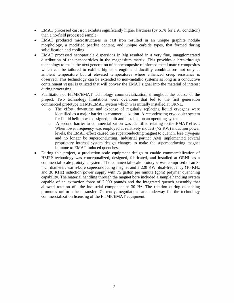
EMAT processed cast iron exhibits significantly higher hardness (by 51% for a 9T condition)
than a no-field processed sample.
EMAT produced microstructures in cast iron resulted in an unique graphite nodule
morphology, a modified pearlite content, and unique carbide types, that formed during
solidification and cooling.
EMAT processed nanoparticle dispersions in Mg resulted in a very fine, unagglomerated
distribution of the nanoparticles in the magnesium matrix. This provides a breakthrough
technology to make the next generation of nanocomposite reinforced metal matrix composites
which can be tailored to exhibit higher strength and ductility combinations not only at
ambient temperature but at elevated temperatures where enhanced creep resistance is
observed. This technology can be extended to non-metallic systems as long as a conductive
containment vessel is utilized that will convey the EMAT signal into the material of interest
during processing.
Facilitation of HTMP/EMAT technology commercialization, throughout the course of the
project. Two technology limitations were overcome that led to the first generation
commercial prototype HTMP/EMAT system which was initially installed at ORNL. o The effort, downtime and expense of regularly replacing liquid cryogens were
identified as a major barrier to commercialization. A recondensing cryocooler system
for liquid helium was designed, built and installed on an operating system.
o A second barrier to commercialization was identified relating to the EMAT effect.
When lower frequency was employed at relatively modest (>2 KW) induction power
levels, the EMAT effect caused the superconducting magnet to quench, lose cryogens
and no longer be superconducting. Industrial partner AMI implemented several
proprietary internal system design changes to make the superconducting magnet
immune to EMAT-induced quenches.
During this project, a production-scale equipment design to enable commercialization of
HMFP technology was conceptualized, designed, fabricated, and installed at ORNL as a
commercial-scale prototype system. The commercial-scale prototype was comprised of an 8-
inch diameter, warm-bore superconducting magnet and a 220 KW, dual-frequency (10 KHz
and 30 KHz) induction power supply with 75 gallon per minute (gpm) polymer quenching
capability. The material handling through the magnet bore included a sample handling system
capable of an extraction force of 2,000 pounds and the integrated quench assembly that
allowed rotation of the industrial component at 30 Hz. The rotation during quenching
promotes uniform heat transfer. Currently, negotiations are underway for the technology
commercialization licensing of the HTMP/EMAT equipment.
3
1. INTRODUCTION
1.1 Description of the Technology
High Magnetic Field Processing (HMFP) is a pivotal and transformational materials processing
technology that can be applied across a broad and diverse spectrum of materials to achieve
comparable and/or superior materials properties at significantly reduced energy- and processing-costs
for high-energy consuming industries. HMFP is superior to conventional thermal processing
methods, and has the potential to achieve or surpass conventionally achieved properties by
eliminating and/or minimizing conventional thermal processing steps. In some cases room
temperature treatment, can be performed resulting in enhanced properties. Energy savings from
implementation of HMFP comes from three facets of magnetic processing: (1) magnetic processing is
a non-thermal process, (2) thermal processes can either be eliminated or process times dramatically
reduced due to enhanced transformation kinetics, and (3) superconducting (SC) magnets are
employed. (SC magnets require no energy once they achieve full field and operate in persistent
mode.)
ORNL prior proof-of-principle efforts on HMFP have demonstrated and documented the following
properties and advantages of ultrahigh magnetic field processing of ferromagnetic materials in the
solid-state:
• Dramatic shifts in phase equilibria and enhanced phase solubilities. New (3-D) phase diagrams
which include magnetic fields, opening up new avenues for major alloy development activities.
Additional “new” phases can now exist in “equilibrium”.
• Increased phase transformation kinetics. Benefits include major energy savings, enhanced process
flexibility, and improved efficiency.
• The production of novel microstructures with enhanced performance. The development of
currently “impossible” microstructures with unique properties is now possible and is applicable to
bulk nanomaterial design efforts (magnetically cycling about a transformation temperature for grain
refinement while still being isothermal).
• A totally new and unique processing (HMFP) methodology to design and engineer new materials
and processing approaches. The technology enables enhanced “Materials by Design” flexibility and
allows residual stress relief for component life extension and improved manufacturability.
1.2 Focus Areas
The primary objectives identified for this project were to:
Demonstrate batch HMFP continuous cooling treatment of ferrous materials with industrial
significance to reduce costs associated with the conventional, high temperature (thermal)
processing treatments that use extended hold-times, and cryogenic processing. The objective
is to develop microstructures that meet specified mechanical properties using a lower cost
treatment.
Investigate the application of HMFP processing in a non-conventional heat treatment process
(meaning not quenched and tempered [Q&T] for a high-performance ferrous alloy such as a
bainite-forming steel and,
Extend HMFP from solid state applications to solidification processes (casting, welding) via
ORNL Electro-magnetic Acoustic Transducer (EMAT) –HMFP technology.
4
1.3 Broad Potential Applications, Energy Savings, Environmental and Economic Benefits
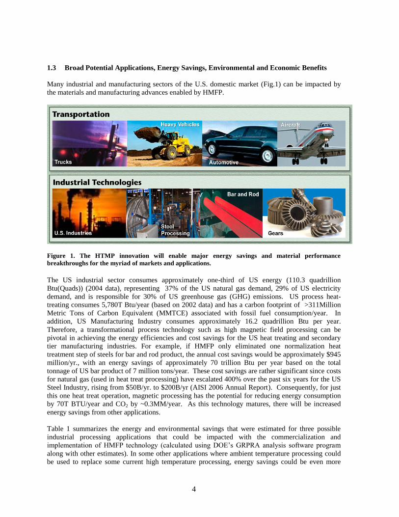
Many industrial and manufacturing sectors of the U.S. domestic market (Fig.1) can be impacted by
the materials and manufacturing advances enabled by HMFP.
Figure 1. The HTMP innovation will enable major energy savings and material performance
breakthroughs for the myriad of markets and applications.
The US industrial sector consumes approximately one-third of US energy (110.3 quadrillion
Btu(Quads)) (2004 data), representing 37% of the US natural gas demand, 29% of US electricity
demand, and is responsible for 30% of US greenhouse gas (GHG) emissions. US process heat-
treating consumes 5,780T Btu/year (based on 2002 data) and has a carbon footprint of >311Million
Metric Tons of Carbon Equivalent (MMTCE) associated with fossil fuel consumption/year. In
addition, US Manufacturing Industry consumes approximately 16.2 quadrillion Btu per year.
Therefore, a transformational process technology such as high magnetic field processing can be
pivotal in achieving the energy efficiencies and cost savings for the US heat treating and secondary
tier manufacturing industries. For example, if HMFP only eliminated one normalization heat
treatment step of steels for bar and rod product, the annual cost savings would be approximately $945
million/yr., with an energy savings of approximately 70 trillion Btu per year based on the total
tonnage of US bar product of 7 million tons/year. These cost savings are rather significant since costs
for natural gas (used in heat treat processing) have escalated 400% over the past six years for the US
Steel Industry, rising from $50B/yr. to $200B/yr (AISI 2006 Annual Report). Consequently, for just
this one heat treat operation, magnetic processing has the potential for reducing energy consumption
by 70T BTU/year and CO2 by ~0.3MM/year. As this technology matures, there will be increased
energy savings from other applications.
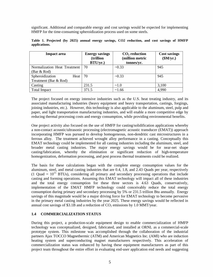
Table 1 summarizes the energy and environmental savings that were estimated for three possible
industrial processing applications that could be impacted with the commercialization and
implementation of HMFP technology (calculated using DOE’s GRPRA analysis software program
along with other estimates). In some other applications where ambient temperature processing could
be used to replace some current high temperature processing, energy savings could be even more
5
significant. Additional and comparable energy and cost savings would be expected for implementing
HMFP for the time-consuming spheroidization process used on some steels.
Table 1. Projected (by 2025) annual energy savings, CO2 reduction, and cost savings of HMFP
applications.
Impact area Energy savings
(trillion
BTU/yr.)
CO2 reduction
(million metric
tonnes/yr.
Cost savings
($M/yr.)
Normalization Heat Treatment
(Bar & Rod)
70 ~0.33 945
Spheroidization Heat
Treatment (Bar & Rod)
70 ~0.33 945
Casting 231.5 ~1.0 3,100
Total Impact 371.5 ~1.66 4,990
The project focused on energy intensive industries such as the U.S. heat treating industry, and its
associated manufacturing industries (heavy equipment and heavy transportation, castings, forgings,
joining industries, etc.). However, this technology is also applicable to the aluminum, steel, pulp and
paper, and light transportation manufacturing industries, and will enable a more competitive edge by
reducing thermal processing costs and energy consumption, while providing environmental benefits.
One project activity also focused on the use of HMFP for casting/solidification applications whereby
a non-contact acoustic/ultrasonic processing (electromagnetic acoustic transducer (EMAT)) approach
incorporating HMFP was pursued to develop homogeneous, non-dendritic cast microstructures in a
ferrous alloy. The treatment achieved wrought alloy performance in a casting. Conceptually this
EMAT technology could be implemented for all casting industries including the aluminum, steel, and
broader metal casting industries. The major energy savings would be for near-net shape
casting/fabrication, whereby the elimination or significant reduction of high-temperature
homogenization, deformation processing, and post process thermal treatments could be realized.
The basis for these calculations began with the complete energy consumption values for the
aluminum, steel, and metal casting industries that are 0.4, 1.8, and 2.43 Quads per year, respectively
(1 Quad = 1015
BTUs), considering all primary and secondary processing operations that include
casting and forming operations. Assuming this EMAT technology will impact all of these industries
and the total energy consumption for these three sectors is 4.63 Quads, conservatively,
implementation of the EMAT HMFP technology could conceivably reduce the total energy
consumption during primary and secondary processing by 5% or 231.5 trillion Btu annually. Energy
savings of this magnitude would be a major driving force for EMAT technology to become pervasive
in the primary metal casting industries by the year 2025. These energy savings would be reflected in
annual cost savings of $3.1B and a reduction of CO2 emissions by 1.0 MMT/year.
1.4 COMMERCIALIZATION STATUS
During this project, a production-scale equipment design to enable commercialization of HMFP
technology was conceptualized, designed, fabricated, and installed at ORNL as a commercial-scale
prototype system. This milestone was accomplished through the collaboration of the industrial
partners Ajax TOCCO Magnethermic (ATM) and American Magnetics Inc. (AMI) who are induction
heating system and superconducting magnet manufacturers respectively. This acceleration of
commercialization status was enhanced by having these equipment manufacturers as part of this
project team throughout the entire effort in evaluating end-user application end needs and suggesting
6
potential commercial H&TMP system designs for their specific applications for possible procurement
after this investigation.
The commercial-scale prototype was comprised of an 8-inch diameter, warm-bore superconducting
magnet and a 220 KW, dual-frequency (10 KHz and 30 KHz) induction power supply with a 75 gpm
polymer quenching unit. The system included a sample handling system, capable of an extraction
force of 2,000 pounds. The integrated quench assembly could rotate the industrial component at 30
Hz during the quenching operation to promote uniform heat transfer conditions. The inner bore of the
superconducting magnet had an internal, water-cooled jacket to prevent accidental heating by the
induction heating coil which might result in a magnet quench (loss of superconducting operating
state). In addition, the superconducting magnet had several unique, proprietary internal modifications
made to mitigate the oscillatory forces from the EMAT effect that might otherwise induce a magnet
quench. Of significant relevance for economical commercial implementation of this technology was
the integration of a cryogen recondensing system to the superconducting magnet assembly which
eliminated the need to periodically replace cryogens. This system is described and shown in great
detail later in this report along with several of the design calculations that were conducted to optimize
the performance of the magnet and the induction heating system.
Currently, negotiations are underway for the technology commercialization licensing of the
HTMP/EMAT equipment. As of this report, several companies have approached the equipment
manufacturers for design and procurement quotes for production-rate capable, commercial systems
for incorporation into their industrial facilities. Of particular relevance is a next generation,
production-rate-capable (up to 300 six-pound gears per hour) HTMP commercial system being
designed by Ajax TOCCO and AMI to be flexible in handling multiple component types for a large,
international company.
7
2. TECHNOLOGY BACKGROUND
2.1 HIGH- AND THERMOMAGNETIC PROCESSING (HTMP) TECHNOLOGY
An applied magnetic field has a direct thermodynamic influence on the chemical potential (Gibbs
Free Energy) of the various phases in a material. This is clearly shown in the following equation for
calculating the Gibbs Free Energy change for the ferrite (), to austenite (), phase transformation in
a Fe-C binary alloy, in the presence of an applied magnetic field:
GFe = RT[ln(aFe)-ln(aFe)] + 0H(MFe - MFe)dH (Equation 1)
M and H are defined as the magnetization and magnetic intensity, respectively. The magnetic effect
will be manifested in the Fe-C binary equilibrium phase diagram as a shift in the transformation
temperatures of the various phases as well as changes in the solubility limits (solvus lines) of the
various phases.
Thermodynamic calculations based on Gibbs Free Energy in the M-H-T (Magnetization-Magnetic
Intensity-Temperature) magnetic equation of state space (f [M, H, T]=0 rather than the conventional
P-V-T [pressure-volume-temperature] space to calculate “conventional” phase diagrams) demonstrate
that significantly different phase equilibria may result for material systems where the product and
parent phases exhibit different magnetization responses. The calculations (based on equation 1) show
that the Gibbs Free Energy is changed by a factor equal to –MdH where M and H (for B=0[H + M]
where B and 0 are the magnetic flux density and magnetic permeability respectively) are the
magnetization and applied field strength, respectively. Since all materials have some form of
ferromagnetism or paramagnetism, magnetic field processing is directly applicable to a broad range
of materials by influencing phase stability and phase transformations in an alloy or compound. The
ability to selectively control microstructural stability and alter transformation kinetics through
appropriate selection of the magnetic field strength promises to provide a very robust mechanism to
develop and tailor enhanced microstructures (even nanostructures through accelerated kinetics) with
superior properties for a broad spectrum of materials.
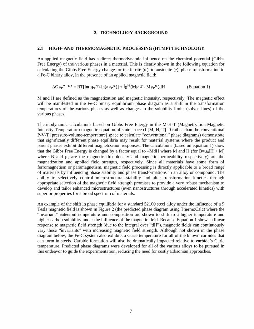
An example of the shift in phase equilibria for a standard 52100 steel alloy under the influence of a 9
Tesla magnetic field is shown in Figure 2 (the predicted phase diagram using ThermoCalc) where the
“invariant” eutectoid temperature and composition are shown to shift to a higher temperature and
higher carbon solubility under the influence of the magnetic field. Because Equation 1 shows a linear
response to magnetic field strength (due to the integral over “dH”), magnetic fields can continuously
vary these “invariants” with increasing magnetic field strength. Although not shown in the phase
diagram below, the Fe-C system also exhibits a Curie temperature for all of the known carbides that
can form in steels. Carbide formation will also be dramatically impacted relative to carbide’s Curie
temperature. Predicted phase diagrams were developed for all of the various alloys to be pursued in
this endeavor to guide the experimentation, reducing the need for costly Edisonian approaches.
8
Figure 2. The shift (blues lines) in the phase boundaries (solvus lines) for a 52100 steel under the
influence of a 9 Tesla magnetic field as predicted using ThermoCalc after this software was modified to
factor in the magnetic free energy term.
This innovative technology results in large process energy savings in three ways: (1) magnetic
processing by itself is a non-thermal process, (2) thermal processes, if needed, can either be
eliminated or process times and temperatures dramatically reduced, and (3) use of energy-efficient
superconducting magnet technology requires no energy to maintain a magnetic field once the magnet
is in persistent mode.
Further reduction in energy use with this technology is achieved by coupling induction heating as the
thermal source when needed. The energy saving occurs through: (1) significantly shorter processing
times (minutes rather than hours) than required for conventional processing methods, (2) equipment
energy consumption is significantly less with operational efficiencies on the order of 80%, and (3)
induction heating coupled with HTMP provides the opportunity to uniquely optimize performance of
both the surface and core microstructures in a component, resulting in higher power density.
2.2 ELECTROMAGNETIC ACOUSTICAL TRANSDUCER (EMAT) TECHNOLOGY
When induction heating is applied in a high magnetic field environment, the induction heating coil is
configured in such a way that high intensity acoustic/ultrasonic treatment occurs naturally. The
resulting configuration is a highly effective electromagnetic acoustical transducer (EMAT). This
approach is unique because the magnetic field strength of the high-field magnet can greatly exceed
that used in a typical EMAT device. As a consequence, the interaction of a high surface current
density (induced via induction heating) with the steady-state high magnet field, results in an
especially effective method for creating a high energy density acoustic environment. The
exceptionally high energy efficiency of the resulting electromagnetic transducer is due to the use of
the high magnetic field, which greatly reduces the current needed to achieve the same acoustic
pressure. EMAT produced in this way provides an efficient non-contact method for applying high-
intensity acoustic/ultrasonic energy to molten and solidified metals. Furthermore, the applied
ultrasonic excitation can be uniformly distributed over most of the surface of the metal sample.
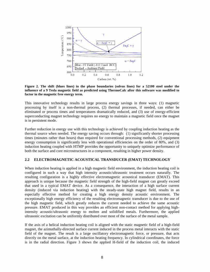
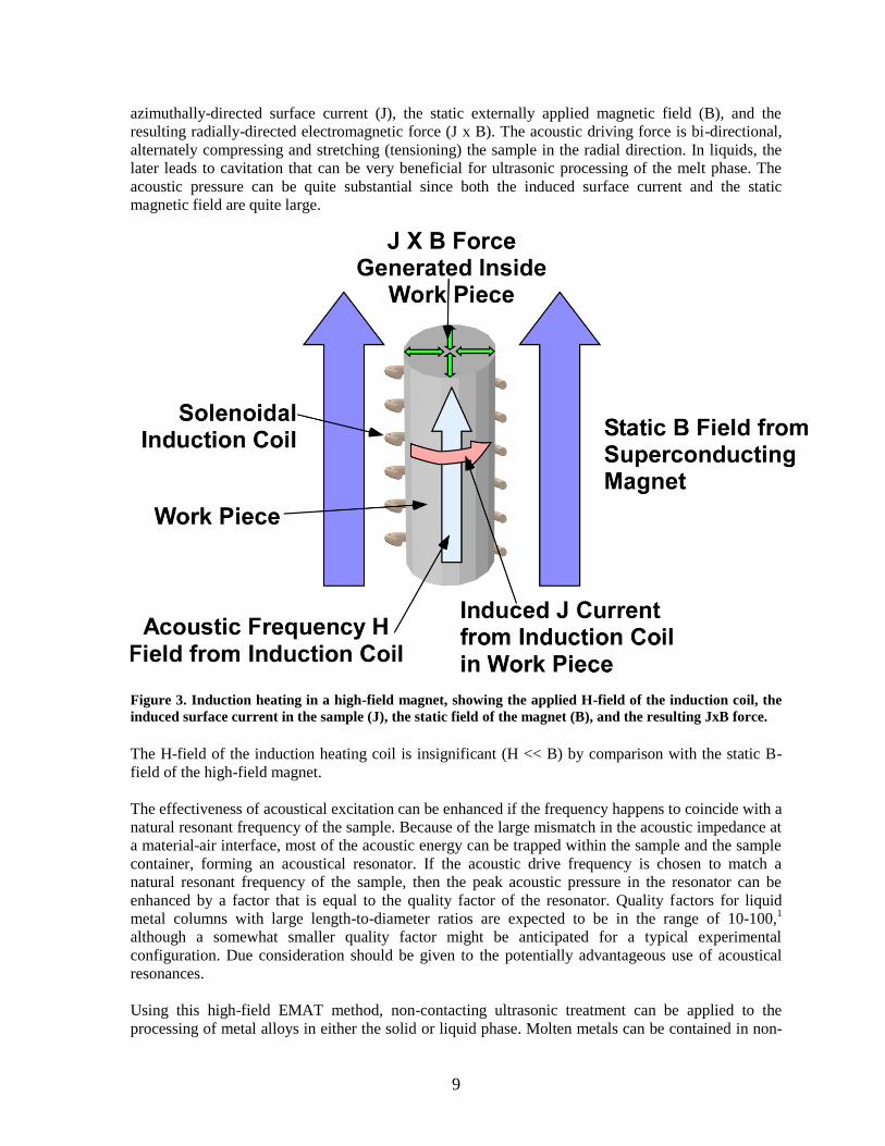
If the axis of a helical induction heating coil is aligned with the static magnetic field of a high-field
magnet, the azimuthally-directed surface current induced in the process metal interacts with the static
field of the magnet. The result is a large oscillatory electromagnetic force, or pressure, that acts
directly on the metal surface, at the induction heating frequency. In cylindrical coordinates, the force
is in the radial direction. Figure 3 shows the applied H-field of the induction coil, the induced
9
azimuthally-directed surface current (J), the static externally applied magnetic field (B), and the
resulting radially-directed electromagnetic force (J x B). The acoustic driving force is bi-directional,
alternately compressing and stretching (tensioning) the sample in the radial direction. In liquids, the
later leads to cavitation that can be very beneficial for ultrasonic processing of the melt phase. The
acoustic pressure can be quite substantial since both the induced surface current and the static
magnetic field are quite large.
Figure 3. Induction heating in a high-field magnet, showing the applied H-field of the induction coil, the
induced surface current in the sample (J), the static field of the magnet (B), and the resulting JxB force.
The H-field of the induction heating coil is insignificant (H << B) by comparison with the static B-
field of the high-field magnet.
The effectiveness of acoustical excitation can be enhanced if the frequency happens to coincide with a
natural resonant frequency of the sample. Because of the large mismatch in the acoustic impedance at
a material-air interface, most of the acoustic energy can be trapped within the sample and the sample
container, forming an acoustical resonator. If the acoustic drive frequency is chosen to match a
natural resonant frequency of the sample, then the peak acoustic pressure in the resonator can be
enhanced by a factor that is equal to the quality factor of the resonator. Quality factors for liquid
metal columns with large length-to-diameter ratios are expected to be in the range of 10-100,1
although a somewhat smaller quality factor might be anticipated for a typical experimental
configuration. Due consideration should be given to the potentially advantageous use of acoustical
resonances.
Using this high-field EMAT method, non-contacting ultrasonic treatment can be applied to the
processing of metal alloys in either the solid or liquid phase. Molten metals can be contained in non-
10
metallic ceramic crucibles that are readily penetrated by the electromagnetic induction fields. Proof-
of-principle experiments have resulted in more homogeneous microstructures in small castings along
with improved casting surface appearance. Therefore, our pioneering experiments show that this non-
contact acoustic/ultrasonic processing technology developed using a high magnetic field in
conjunction with induction heating has significant promise in impacting commercial casting
applications with the potential to develop wrought-like microstructures in as-cast components.
2.3 QUALIFICATIONS AND RELEVANT EXPERTISE OF THE PROJECT TEAM
The success-focused project team for this project integrated the technology and original equipment
pioneer/innovator staff from ORNL with four major innovative-technology end-user organizations;
Carpenter Technologies, DuraBar, Caterpillar, and American Safety Razor. The team was further
enhanced by equipment manufacturers, Ajax TOCCO and AMI, who were involved throughout the
entire effort in evaluating end-user applications and potential commercial HTMP system designs.
This has been a proven teaming concept for successful HTMP technology evaluation and
commercialization pursuits, as demonstrated in the recent EERE Advanced Manufacturing Office EIP
Eaton-led project (CPS Agreement Number: 18300) involving ORNL, Ajax TOCCO, and AMI that
has resulted in the initial design concepts being formulated for a HTMP system rated for 300 six-
pound gears per hour. The EIP team led by ORNL won an R&D 100 Award in 2009 for advancing
HTMP from a research curiosity to a commercially-viable technology demonstrated on real industrial
components and protected by multiple U.S. patents.
ORNL has significant experience developing and commercializing innovative technologies as it has
won over 160 R&D 100 awards. The awards are indicative of the focus the organization has taken in
moving innovative concepts in materials and technologies through the proof-of-principle and
demonstration phases, to implementation in the marketplace. Similarly, Ajax TOCCO and AMI build
and deliver their unique and revolutionary systems throughout the worldwide marketplace as they are
world-class technology leaders in their specific markets.
11
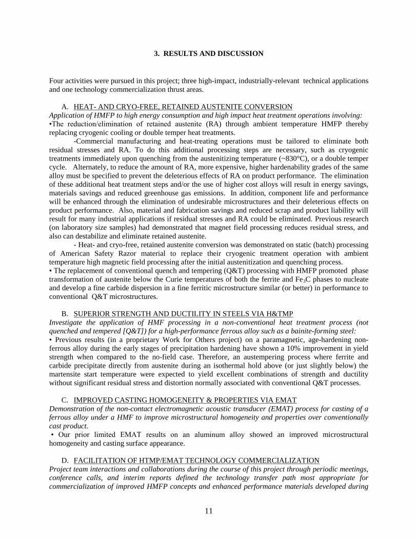
3. RESULTS AND DISCUSSION
Four activities were pursued in this project; three high-impact, industrially-relevant technical applications
and one technology commercialization thrust areas.
A. HEAT- AND CRYO-FREE, RETAINED AUSTENITE CONVERSION
Application of HMFP to high energy consumption and high impact heat treatment operations involving:
•The reduction/elimination of retained austenite (RA) through ambient temperature HMFP thereby
replacing cryogenic cooling or double temper heat treatments.
-Commercial manufacturing and heat-treating operations must be tailored to eliminate both
residual stresses and RA. To do this additional processing steps are necessary, such as cryogenic
treatments immediately upon quenching from the austenitizing temperature (~830°C), or a double temper
cycle. Alternately, to reduce the amount of RA, more expensive, higher hardenability grades of the same
alloy must be specified to prevent the deleterious effects of RA on product performance. The elimination
of these additional heat treatment steps and/or the use of higher cost alloys will result in energy savings,
materials savings and reduced greenhouse gas emissions. In addition, component life and performance
will be enhanced through the elimination of undesirable microstructures and their deleterious effects on
product performance. Also, material and fabrication savings and reduced scrap and product liability will
result for many industrial applications if residual stresses and RA could be eliminated. Previous research
(on laboratory size samples) had demonstrated that magnet field processing reduces residual stress, and
also can destabilize and eliminate retained austenite.
- Heat- and cryo-free, retained austenite conversion was demonstrated on static (batch) processing
of American Safety Razor material to replace their cryogenic treatment operation with ambient
temperature high magnetic field processing after the initial austenitization and quenching process.
• The replacement of conventional quench and tempering (Q&T) processing with HMFP promoted phase
transformation of austenite below the Curie temperatures of both the ferrite and Fe3C phases to nucleate
and develop a fine carbide dispersion in a fine ferritic microstructure similar (or better) in performance to
conventional Q&T microstructures.
B. SUPERIOR STRENGTH AND DUCTILITY IN STEELS VIA H&TMP
Investigate the application of HMF processing in a non-conventional heat treatment process (not
quenched and tempered [Q&T]) for a high-performance ferrous alloy such as a bainite-forming steel:
• Previous results (in a proprietary Work for Others project) on a paramagnetic, age-hardening non-
ferrous alloy during the early stages of precipitation hardening have shown a 10% improvement in yield
strength when compared to the no-field case. Therefore, an austempering process where ferrite and
carbide precipitate directly from austenite during an isothermal hold above (or just slightly below) the
martensite start temperature were expected to yield excellent combinations of strength and ductility
without significant residual stress and distortion normally associated with conventional Q&T processes.
C. IMPROVED CASTING HOMOGENEITY & PROPERTIES VIA EMAT
Demonstration of the non-contact electromagnetic acoustic transducer (EMAT) process for casting of a
ferrous alloy under a HMF to improve microstructural homogeneity and properties over conventionally
cast product.
• Our prior limited EMAT results on an aluminum alloy showed an improved microstructural
homogeneity and casting surface appearance.
D. FACILITATION OF HTMP/EMAT TECHNOLOGY COMMERCIALIZATION
Project team interactions and collaborations during the course of this project through periodic meetings,
conference calls, and interim reports defined the technology transfer path most appropriate for
commercialization of improved HMFP concepts and enhanced performance materials developed during
12
the course of this project.
During the course of this project the current technology limitations of the superconducting
magnet and induction heating systems were identified. New HTMP systems were designed that overcome
those issues leading to the design of the first generation commercial prototype HTMP/EMAT capable
system. The commercial prototype was initially installed at ORNL.
3.1 HEAT- AND CRYO-FREE, RETAINED AUSTENITE CONVERSION
Retained austenite is deleterious in many materials applications because under external stress this phase
can transform to high carbon martensite, which is very brittle and can lead to catastrophic failure in
service. In applications such as high-speed bearings, which are machined to very high tolerances, the
transformation of RA under load leads to a large, positive volume strain (~4%) that can result in bearing
seizure.
The presence of retained austenite upon quenching to room temperature is a major heat treatment concern
requiring rapid transfer of the quenched components to an alternate quench facility where cryogenic
treatments are performed to drive the transformation of austenite to completion. Generally, this additional
processing step still leaves a residual amount of retained austenite. Alternately, multiple tempering heat
treatments are employed to successively temper the initial martensite and form additional martensite from
the residual retained austenite. The secondarily transformed austenite must be re-tempered to the desired
ferrite and carbide microstructure. The elimination of these additional heat treatment steps will result in
huge energy savings and reduced greenhouse gases.
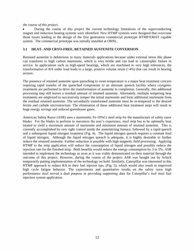
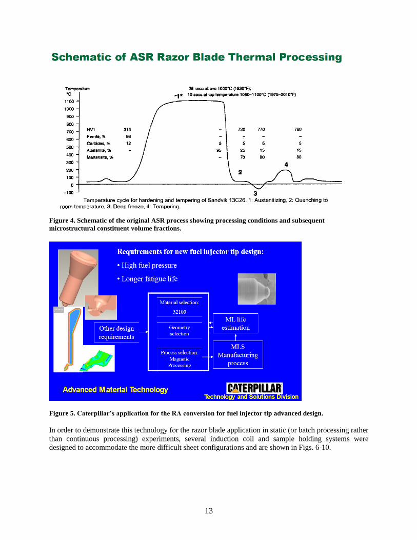
American Safety Razor (ASR) uses a martensitic Fe-10%Cr steel strip for the manufacture of safety razor
blades. For the blades to perform to maximize the user’s experience, steel strip has to be optimally heat
treated to yield a maximum amount of martensite and minimum amount of retained austenite. This is
currently accomplished by very tight control inside the austenitizing furnace, followed by a rapid quench
and a subsequent liquid nitrogen treatment (Fig. 4). The liquid nitrogen quench requires a constant feed
of liquid nitrogen. Although the liquid nitrogen quench is adequate, it is highly desirable to further
reduce the retained austenite. Further reduction is possible with high magnetic field processing. Applying
HTMP to the strip application will reduce the consumption of liquid nitrogen and possibly reduce the
rejection rate for the finished strip. Both benefits would reduce the energy consumption by 3 to 5%. ASR
intended to implement the technology as soon as it was viably demonstrated on their material through the
outcome of this project. However, during the course of the project ASR was bought out by Schick
temporarily putting implementation of the technology on hold. Similarly, Caterpillar was interested in this
HTMP approach to reduce RA in their fuel injector tips, (Fig. 5), which would also result in improved
high cycle fatigue behavior. The experiments and quantitative results on the safety razor high
performance steel served a dual purpose in providing supporting data for Caterpillar’s tool steel fuel
injection system application.
13
Figure 4. Schematic of the original ASR process showing processing conditions and subsequent
microstructural constituent volume fractions.
Figure 5. Caterpillar’s application for the RA conversion for fuel injector tip advanced design.
In order to demonstrate this technology for the razor blade application in static (or batch processing rather
than continuous processing) experiments, several induction coil and sample holding systems were
designed to accommodate the more difficult sheet configurations and are shown in Figs. 6-10.

14
Figure 6. Induction coil designs used in initial experiments to develop uniform temperatures across the entire
face of the safety razor strip.
Figure 7. A novel spring holding design was employed to keep the razor strip in tension while applying the
HTMP process for the thermal transient.
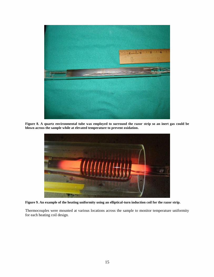
15
Figure 8. A quartz environmental tube was employed to surround the razor strip so an inert gas could be
blown across the sample while at elevated temperature to prevent oxidation.
Figure 9. An example of the heating uniformity using an elliptical-turn induction coil for the razor strip.
Thermocouples were mounted at various locations across the sample to monitor temperature uniformity
for each heating coil design.
16
Figure 10. Two parallel flat induction heating coils could not achieve temperature uniformity and so the
design in Fig. 9 was used in the batch processing experiments.
3.1.1 Material Characterization
Characterization and delineation of retained austenite from carbides in stainless steel was accomplished
by combined electron backscatter electron diffraction (EBSD), energy dispersive spectroscopy- energy
dispersive X-ray (EDS-EDX)), and X-ray diffraction (XRD). Measurement of the volume fraction, grain
size, and crystallographic texture of the ferritic (or martensitic) matrix, the retained austenite, and
carbides (if present), was essential to understanding the steel’s processing-properties relationships.
Normally electron backscatter diffraction (EBSD) is a good tool for RA measurement, however RA-
containing steels are challenging because the cubic phases give similar EBSD patterns [1]. In this work, a
thermomagnetically processed (TMP) Fe-13.0Cr-0.7Mn-0.4Si-0.68C steel (hot-rolled thin strip) was
analyzed with XRD and found to contain a ferritic/martensitic matrix, RA, and M23C6 carbides. However,
overlapping XRD peaks and strong texture made it difficult to quantify the RA volume fraction, which is
a vital metric to compare processing paths.
After XRD analysis the Fe-13.0Cr-0.7Mn-0.4Si-0.68C steel was polished in colloidal silica and analyzed
using EBSD in a JEOL6500F Scanning Electron Microscope (SEM) with a Hikari EDX system. An area
of 3030m was analyzed using 100nm steps and a 10kV, 3.0nA probe. Figs. 11a, 11b, and 11c show the
SEM image, the phase map, and the confidence index (CI), respectively, not including chemical
information. Clearly, the phase map in Fig. 11b is meaningless, with both ferrite and M23C6 giving ~45
area% each, and the CI’s in Fig. 11c are poor ("ferrite" refers to BCC ferrite and BCT martensite phases -
the martensite tetragonality was insufficient to index). Since all three phases are cubic, the EBSD
patterns are similar and the EBSD algorithm is unable to find unique solutions for phase/compound
delineation despite using a large number of Hough peaks (12-15) for indexing.
17
Figure 11. (a) SEM image of polished sample - box indicates 30 x 30m EBSD scan area, (b) EBSD phase
map, and (c) Confidence Index map.
The phase map was acquired simultaneously with elemental maps via EDS. Fig. 12a shows an image
quality (IQ) map, and Figs. 12b and 12c show the Fe and Cr X-ray maps, respectively. Fig. 12d shows a
red-blue-yellow-magenta map of four partitions identified by statistical analysis using EDX Orientation
Imaging Microscopy software of the Cr, Fe, and IQ maps. The Hough peaks were re-indexed offline with
the red partition restricted to ferrite + austenite, yellow to austenite + M23C6, and blue and magenta to
M23C6, M7C3 and Fe3C, respectively.
Figure 12. (a) Image quality map, (b) Fe X-ray map,(c) Cr X-ray map, and (d) automated partitioning of the
IQ+Fe+Cr maps into four regions for re-indexing.
Figs. 13a and 13b show the re-indexed phase map and the CI map, respectively. From the re-indexed
data, the RA is approximately 7.1 area%, a qualitatively reasonable number and M7C3 and Fe3C are both
approximately 1 area%, indicating they are not likely present but are simply mis-indexing artifacts.
Clearly, the indexing in Fig. 13a is more consistent and the confidence (Fig. 13b) is higher compared to
Fig. 11. Therefore, combining EDS and EBSD is a very reasonable approach for resolving the problem of
identifying cubic carbides in a matrix of ferrite/martensite and austenite. Problems to still be addressed
18
are surface relief from sample preparation (resulting in lowered IQ near harder phases) and the
intrinsically different spatial resolution in EBSD and EDS signal generation [2].
Figure 13. (a) Re-indexed phase map using chemical information. (b) Confidence index map using chemical
information.
Acknowledging the precision limits of RA determination, the analysis showed that the ambient
temperature HTMP processing dramatically reduced RA from values on the order of 25% to extremely
low levels (Fig. 13a). The results were highly desired for the razor strip and were applied to the RA
reduction applications for Caterpillar’s fuel injection nozzle.
3.2 SUPERIOR STRENGTH AND DUCTILITY IN STEELS VIA HTMP
Carpenter Technologies provided ORNL a bainitic high strength alloy steel and the accompanying
processing history, as–received material microstructural characterization (optical/SEM metallography,
grain size), the mechanical properties, and sufficient materials needed to conduct the experiments agreed
upon in this focus area. Since continuous cooling transformation (CCT) information did not exist for the
steel, ORNL developed the CCT using dilatometer specimens supplied by Carpenter Technologies.
Carpenter machined the mechanical property test specimens for ORNL to Thermo-magnetically process
and Carpenter performed all the mechanical testing. ORNL determined via dilatometry how the
martensite start temperature shifted with magnetic processing. This effort was necessary in order to define
the process control parameters for the high magnetic field experiments. Knowing the CCT curves prior to
high magnetic field processing aided in guiding ORNL in determining the thermo-magnetic processing
temperatures needed to obtain the proper/optimized heat treatment practices.
Carpenter Technologies staff, upon review of their ferrous alloy systems, down-selected two candidate
alloys for proof-of-principal HMFP experiments. One was their Custom 465 stainless steel alloy, the
other was a new, high strength bainitic alloy. The reason for evaluating the Custom 465 stainless steel
was that in thick cross sections (e.g., >8-inches in diameter) this alloy developed RA upon cooling.
Experiments run on this alloy on smaller diameter samples (~0.5-inch) that fit inside the induction coil in
the bore of our SC magnet system could not duplicate the formation of the RA because of the inherent
higher quench rates achievable in these smaller samples for even the no-field cases. No further
experiments were conducted and details of that limited investigation on the Custom 465 alloy will not be
reported here. The materials characterization results for the bainitic alloy are detailed below.
3.2.1 High Strength Bainitic Alloy

19
The chemical composition of the high strength bainitic alloy is shown in Table 2. The alloy is used in the
austenitized + quenched + cryogenic treatment + tempered condition. The primary goal in processing the
alloy was to develop a more energy-efficient thermal magnetic processing sequence that would eliminate
the energy-intensive cryogenic processing step that is currently needed to reduce the amount of retained
austenite in the alloy. The mechanical properties and performance of the alloy are strongly influenced by
the % retained austenite.
Table 2. Chemical Composition of super bainitic alloy (Heat 010964)
Element C Mn Si P S Cr Ni Cu V Ti Al N [ppm]
O
[ppm]
wt.% 0.36 0.78 0.94 <.005 <.0005 1.26 3.81 0.52 0.30 <.003 .004 <10 <10
3.2.1.1 Materials Characterization
To determine/establish the important phase transformation temperatures prior to planning the targeted
TMP experiments for this material, Carpenter provided mechanical and dilatometer test samples to
ORNL, ORNL performed high speed quenching dilatometry experiments on the samples using a high
quench rate Figure 14 shows that the martensite start temperature was determined to be 238C. As a
comparison, the martensite start temperature was also estimated by using the standard Andrews equation,
i.e.,
Martensite start (K) = 785–453C-16.9Ni-15Cr-9.5Mo+217C*C-71.5C*Mn-67.6C*Cr
Using this equation, the martensite start temperature was estimated to be 243˚C, showing excellent
agreement between the predicted/estimated and actual experimental values determined for the martensite
start temperature.
Figure 14. The experimentally determined martensite start (Ms) phase transition temperature (238˚C) for a
baseline steel composition using high speed quenching dilatometry techniques during high speed helium gas
quenching (>200˚C/s) from the austenite single phase field.
20
ORNL performed metallographic evaluations to characterize the bainitic steel samples processed with no-
field and with magnetic field processing. The characterization demonstrated a profound difference in
microstructure between the two processing routes. Figure 15 shows the striking distinction in the
microstructural response of this alloy by aging with and without a magnetic field imposed. Aging in the
presence of a magnetic field appears to essentially eliminate the obvious “banding” that results following
aging this alloy without a magnetic field imposed during aging. Consequently, aging under the influence
of a magnetic field appears to significantly reduce the banded/periodic structure that resulted without a
magnetic field imposed. In other alloys, this type of banding is typically associated with local chemistry
variations (apparent alloy segregation). Thermal magnetic processing appears to homogenize the alloy on
a micro scale resulting in a uniform microstructure throughout the bulk.
Figure 15. Preliminary metallographic micrographs of a high strength bainitic alloy austenitized and aged for
8 hrs without (Fig. 15 a & c), the No Field (NF) condition and with (Fig. 15 b & d) a magnetic field (9T)
indicate that magnetic field processing appears to refine the microstructure ((Fig. 15 a vs. b: transverse view)
and significantly reduce the banded structure ((Fig 15 c vs. d: longitudinal view) when compared to the no-
field conditions.
3.2.1.2 Mechanical Properties
Using the experimentally determined martensite start phase transformation temperature of 238oC for the
bainitic steel alloy, a test matrix was developed to investigate and determine the influence that
thermomagnetic processing has on mechanical properties after austempering tensile and Charpy impact
tests conducted on samples with and without HTMP. HTMP samples had higher yield strength, slightly
lower ultimate strength, higher % elongation and % reduction in area, and increased energy absorption
compared to the no-field (NF) trials. While the lower ultimate strength and increased elongation and
increased energy absorption during impact testing could be explained by the temperature difference
21
between the two trials, the higher yield strength indicates that the magnetic field narrowed the gap
between the yield strength and the ultimate tensile strength. This narrowing of the gap is considered
favorable for some industrial applications.
Table 3 summarizes the property data and demonstrates that HMFP results in significant improvements in
mechanical property performance. The TMP results represent a major breakthrough in materials property
enhancements not previously attained. Namely, both strength and ductility are simultaneously improved.
These mechanical property results are unprecedented, and cannot be achieved by any other processing
method. These results demonstrate that TMP can provide simultaneous improvements in yield strength
and percent elongation. For this bainitic steel alloy12 %, 10%, 13%, and 22% increases in yield strength,
elongation, reduction-in-area, and impact energy, respectively were achieved.
Table 3. Mechanical property results for this high strength bainitic alloy demonstrate that HTMP processing
produces unprecedented, and simultaneous improvements in both yield strength and ductility.
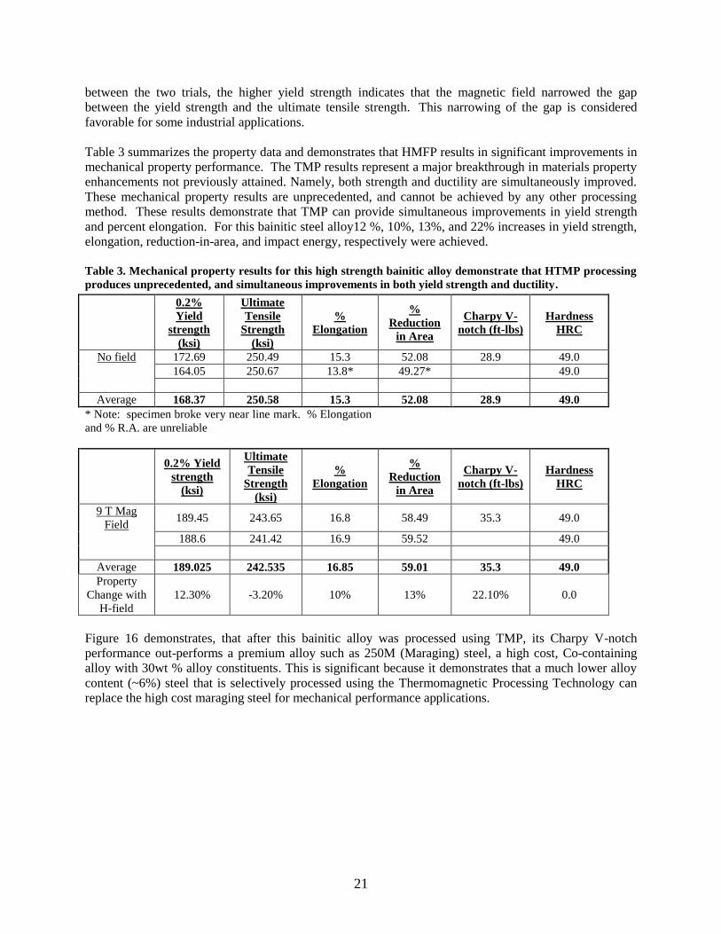
Figure 16 demonstrates, that after this bainitic alloy was processed using TMP, its Charpy V-notch
performance out-performs a premium alloy such as 250M (Maraging) steel, a high cost, Co-containing
alloy with 30wt % alloy constituents. This is significant because it demonstrates that a much lower alloy
content (~6%) steel that is selectively processed using the Thermomagnetic Processing Technology can
replace the high cost maraging steel for mechanical performance applications.
0.2%
Yield
strength
(ksi)
Ultimate
Tensile
Strength
(ksi)
%
Elongation
%
Reduction
in Area
Charpy V-
notch (ft-lbs)
Hardness
HRC
No field 172.69 250.49 15.3 52.08 28.9 49.0
164.05 250.67 13.8* 49.27* 49.0
Average 168.37 250.58 15.3 52.08 28.9 49.0
* Note: specimen broke very near line mark. % Elongation
and % R.A. are unreliable
0.2% Yield
strength
(ksi)
Ultimate
Tensile
Strength
(ksi)
%
Elongation
%
Reduction
in Area
Charpy V-
notch (ft-lbs)
Hardness
HRC
9 T Mag
Field 189.45 243.65 16.8 58.49 35.3 49.0
188.6 241.42 16.9 59.52 49.0
Average 189.025 242.535 16.85 59.01 35.3 49.0
Property
Change with
H-field
12.30% -3.20% 10% 13% 22.10% 0.0
22
Figure 16. Charpy V-notch property results for this high strength bainitic alloy out-perform maraging 250
steel.
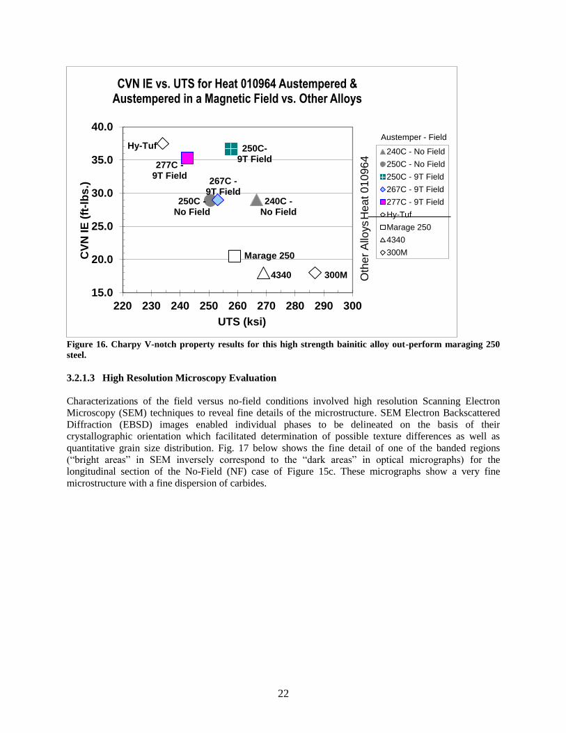
3.2.1.3 High Resolution Microscopy Evaluation
Characterizations of the field versus no-field conditions involved high resolution Scanning Electron
Microscopy (SEM) techniques to reveal fine details of the microstructure. SEM Electron Backscattered
Diffraction (EBSD) images enabled individual phases to be delineated on the basis of their
crystallographic orientation which facilitated determination of possible texture differences as well as
quantitative grain size distribution. Fig. 17 below shows the fine detail of one of the banded regions
(“bright areas” in SEM inversely correspond to the “dark areas” in optical micrographs) for the
longitudinal section of the No-Field (NF) case of Figure 15c. These micrographs show a very fine
microstructure with a fine dispersion of carbides.
15.0
20.0
25.0
30.0
35.0
40.0
220 230 240 250 260 270 280 290 300
CV
N I
E (
ft-l
bs
.)
UTS (ksi)
CVN IE vs. UTS for Heat 010964 Austempered & Austempered in a Magnetic Field vs. Other Alloys
240C - No Field
250C - No Field
250C - 9T Field
267C - 9T Field
277C - 9T Field
Hy-Tuf
Marage 250
4340
300M
300M 4340
Marage 250
Hy-Tuf
240C - No Field
250C - No Field
250C- 9T Field
267C - 9T Field
277C - 9T Field
Austemper - Field
Hea
t 0
10
96
4
Oth
er
Allo
ys

23
Figure 17. Scanning Electron Microscopy (SEM) micrographs of the NF (no-field) longitudinal section
exhibiting very fine microstructural features (possibly a fine carbide dispersion) for a region that appears
bright in the SEM (opposite to perspective in optical micrographs).
Similar examination of the alternating contrast banded region in this longitudinal no field sample using
SEM shows a fine microstructure (Fig. 18) but with different morphological features (note the dominance
of fine spherical carbides). Fig. 19 is an SEM image from material processed with the 9 T magnetic
field. The longitudinal sample shows microstructural differences between the bright and dark regions
observed in the optical micrographs.
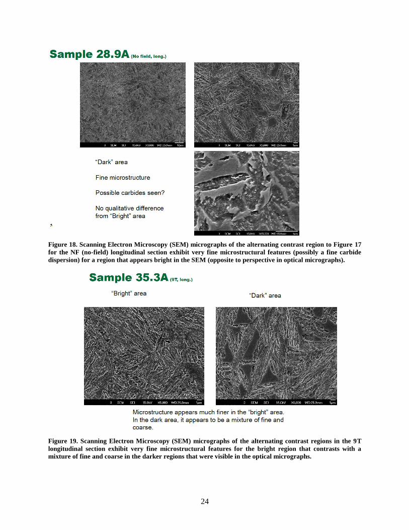
24
Figure 18. Scanning Electron Microscopy (SEM) micrographs of the alternating contrast region to Figure 17
for the NF (no-field) longitudinal section exhibit very fine microstructural features (possibly a fine carbide
dispersion) for a region that appears bright in the SEM (opposite to perspective in optical micrographs).
Figure 19. Scanning Electron Microscopy (SEM) micrographs of the alternating contrast regions in the 9T
longitudinal section exhibit very fine microstructural features for the bright region that contrasts with a
mixture of fine and coarse in the darker regions that were visible in the optical micrographs.
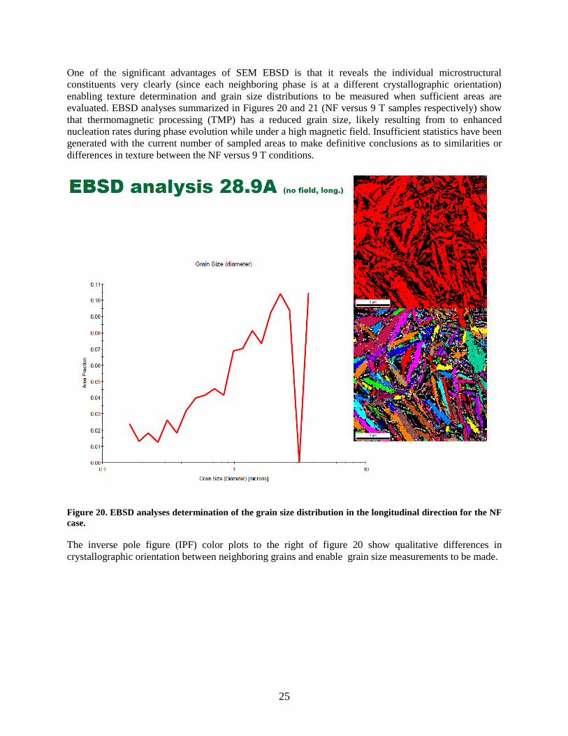
25
One of the significant advantages of SEM EBSD is that it reveals the individual microstructural
constituents very clearly (since each neighboring phase is at a different crystallographic orientation)
enabling texture determination and grain size distributions to be measured when sufficient areas are
evaluated. EBSD analyses summarized in Figures 20 and 21 (NF versus 9 T samples respectively) show
that thermomagnetic processing (TMP) has a reduced grain size, likely resulting from to enhanced
nucleation rates during phase evolution while under a high magnetic field. Insufficient statistics have been
generated with the current number of sampled areas to make definitive conclusions as to similarities or
differences in texture between the NF versus 9 T conditions.
Figure 20. EBSD analyses determination of the grain size distribution in the longitudinal direction for the NF
case.
The inverse pole figure (IPF) color plots to the right of figure 20 show qualitative differences in
crystallographic orientation between neighboring grains and enable grain size measurements to be made.
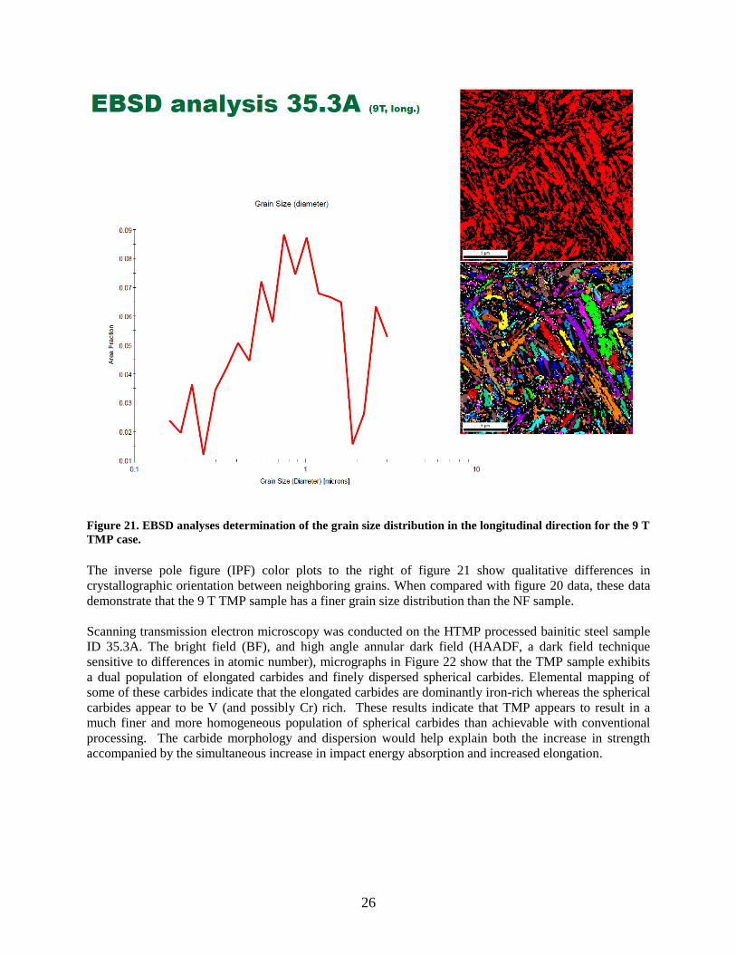
26
Figure 21. EBSD analyses determination of the grain size distribution in the longitudinal direction for the 9 T
TMP case.
The inverse pole figure (IPF) color plots to the right of figure 21 show qualitative differences in
crystallographic orientation between neighboring grains. When compared with figure 20 data, these data
demonstrate that the 9 T TMP sample has a finer grain size distribution than the NF sample.
Scanning transmission electron microscopy was conducted on the HTMP processed bainitic steel sample
ID 35.3A. The bright field (BF), and high angle annular dark field (HAADF, a dark field technique
sensitive to differences in atomic number), micrographs in Figure 22 show that the TMP sample exhibits
a dual population of elongated carbides and finely dispersed spherical carbides. Elemental mapping of
some of these carbides indicate that the elongated carbides are dominantly iron-rich whereas the spherical
carbides appear to be V (and possibly Cr) rich. These results indicate that TMP appears to result in a
much finer and more homogeneous population of spherical carbides than achievable with conventional
processing. The carbide morphology and dispersion would help explain both the increase in strength
accompanied by the simultaneous increase in impact energy absorption and increased elongation.
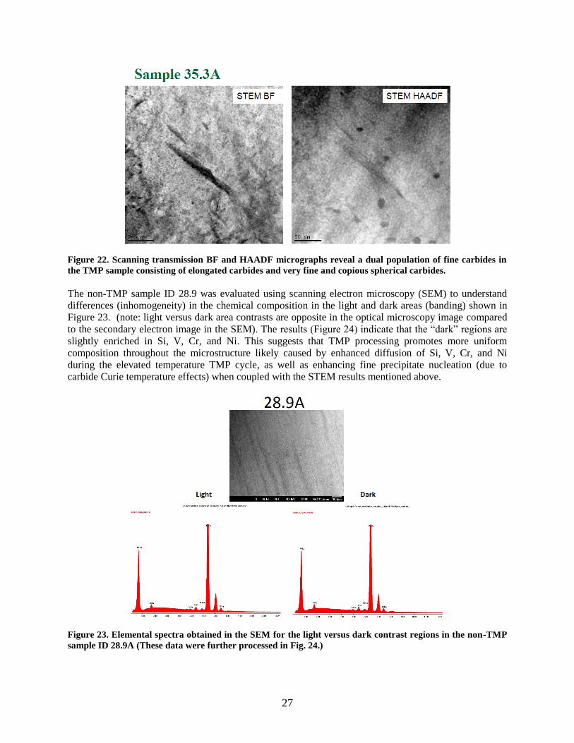
27
Figure 22. Scanning transmission BF and HAADF micrographs reveal a dual population of fine carbides in
the TMP sample consisting of elongated carbides and very fine and copious spherical carbides.
The non-TMP sample ID 28.9 was evaluated using scanning electron microscopy (SEM) to understand
differences (inhomogeneity) in the chemical composition in the light and dark areas (banding) shown in
Figure 23. (note: light versus dark area contrasts are opposite in the optical microscopy image compared
to the secondary electron image in the SEM). The results (Figure 24) indicate that the “dark” regions are
slightly enriched in Si, V, Cr, and Ni. This suggests that TMP processing promotes more uniform
composition throughout the microstructure likely caused by enhanced diffusion of Si, V, Cr, and Ni
during the elevated temperature TMP cycle, as well as enhancing fine precipitate nucleation (due to
carbide Curie temperature effects) when coupled with the STEM results mentioned above.
Figure 23. Elemental spectra obtained in the SEM for the light versus dark contrast regions in the non-TMP
sample ID 28.9A (These data were further processed in Fig. 24.)
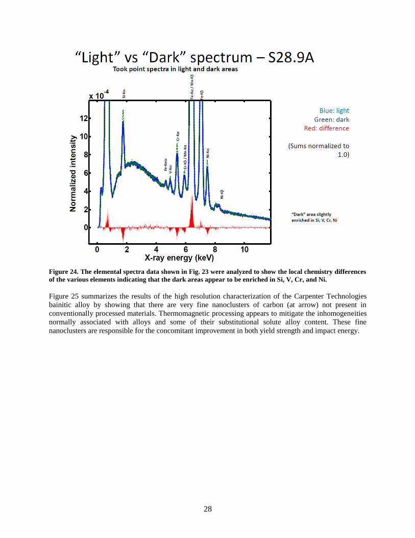
28
Figure 24. The elemental spectra data shown in Fig. 23 were analyzed to show the local chemistry differences
of the various elements indicating that the dark areas appear to be enriched in Si, V, Cr, and Ni.
Figure 25 summarizes the results of the high resolution characterization of the Carpenter Technologies
bainitic alloy by showing that there are very fine nanoclusters of carbon (at arrow) not present in
conventionally processed materials. Thermomagnetic processing appears to mitigate the inhomogeneities
normally associated with alloys and some of their substitutional solute alloy content. These fine
nanoclusters are responsible for the concomitant improvement in both yield strength and impact energy.
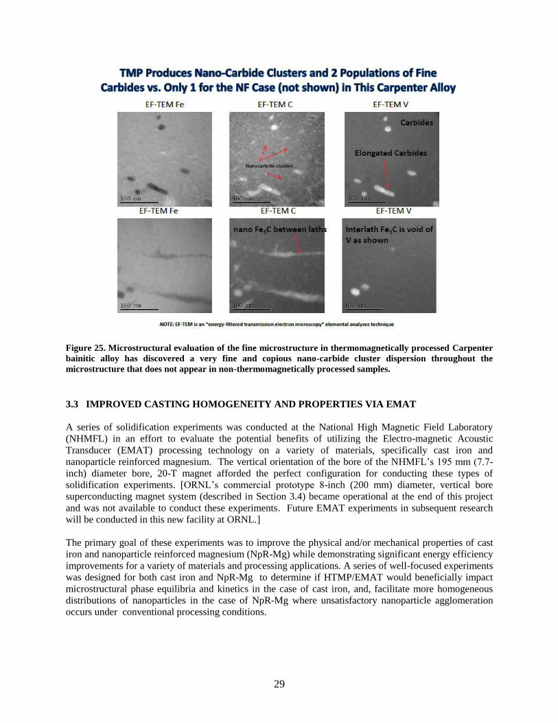
29
Figure 25. Microstructural evaluation of the fine microstructure in thermomagnetically processed Carpenter
bainitic alloy has discovered a very fine and copious nano-carbide cluster dispersion throughout the
microstructure that does not appear in non-thermomagnetically processed samples.
3.3 IMPROVED CASTING HOMOGENEITY AND PROPERTIES VIA EMAT
A series of solidification experiments was conducted at the National High Magnetic Field Laboratory
(NHMFL) in an effort to evaluate the potential benefits of utilizing the Electro-magnetic Acoustic
Transducer (EMAT) processing technology on a variety of materials, specifically cast iron and
nanoparticle reinforced magnesium. The vertical orientation of the bore of the NHMFL’s 195 mm (7.7-
inch) diameter bore, 20-T magnet afforded the perfect configuration for conducting these types of
solidification experiments. [ORNL’s commercial prototype 8-inch (200 mm) diameter, vertical bore
superconducting magnet system (described in Section 3.4) became operational at the end of this project
and was not available to conduct these experiments. Future EMAT experiments in subsequent research
will be conducted in this new facility at ORNL.]
The primary goal of these experiments was to improve the physical and/or mechanical properties of cast
iron and nanoparticle reinforced magnesium (NpR-Mg) while demonstrating significant energy efficiency
improvements for a variety of materials and processing applications. A series of well-focused experiments
was designed for both cast iron and NpR-Mg to determine if HTMP/EMAT would beneficially impact
microstructural phase equilibria and kinetics in the case of cast iron, and, facilitate more homogeneous
distributions of nanoparticles in the case of NpR-Mg where unsatisfactory nanoparticle agglomeration
occurs under conventional processing conditions.
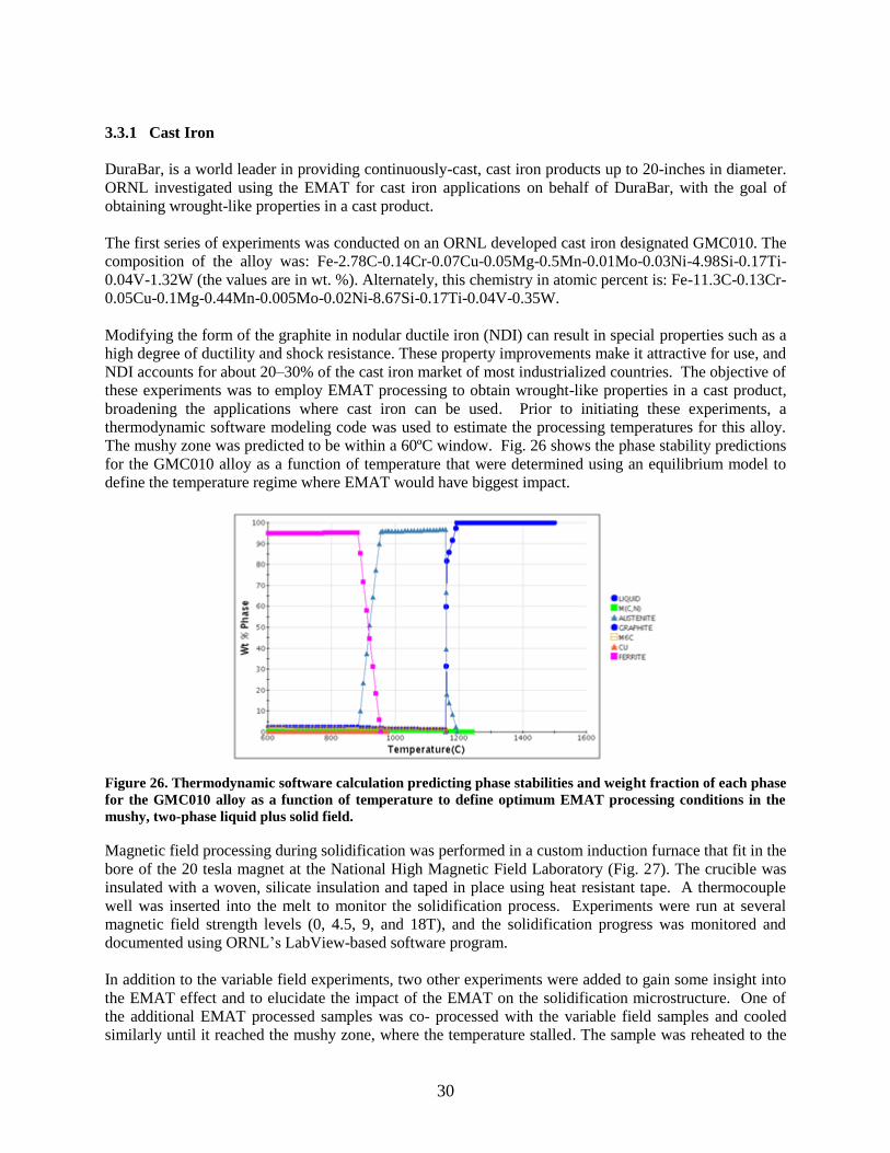
30
3.3.1 Cast Iron
DuraBar, is a world leader in providing continuously-cast, cast iron products up to 20-inches in diameter.
ORNL investigated using the EMAT for cast iron applications on behalf of DuraBar, with the goal of
obtaining wrought-like properties in a cast product.
The first series of experiments was conducted on an ORNL developed cast iron designated GMC010. The
composition of the alloy was: Fe-2.78C-0.14Cr-0.07Cu-0.05Mg-0.5Mn-0.01Mo-0.03Ni-4.98Si-0.17Ti-
0.04V-1.32W (the values are in wt. %). Alternately, this chemistry in atomic percent is: Fe-11.3C-0.13Cr-
0.05Cu-0.1Mg-0.44Mn-0.005Mo-0.02Ni-8.67Si-0.17Ti-0.04V-0.35W.
Modifying the form of the graphite in nodular ductile iron (NDI) can result in special properties such as a
high degree of ductility and shock resistance. These property improvements make it attractive for use, and
NDI accounts for about 20–30% of the cast iron market of most industrialized countries. The objective of
these experiments was to employ EMAT processing to obtain wrought-like properties in a cast product,
broadening the applications where cast iron can be used. Prior to initiating these experiments, a
thermodynamic software modeling code was used to estimate the processing temperatures for this alloy.
The mushy zone was predicted to be within a 60ºC window. Fig. 26 shows the phase stability predictions
for the GMC010 alloy as a function of temperature that were determined using an equilibrium model to
define the temperature regime where EMAT would have biggest impact.
Figure 26. Thermodynamic software calculation predicting phase stabilities and weight fraction of each phase
for the GMC010 alloy as a function of temperature to define optimum EMAT processing conditions in the
mushy, two-phase liquid plus solid field.
Magnetic field processing during solidification was performed in a custom induction furnace that fit in the
bore of the 20 tesla magnet at the National High Magnetic Field Laboratory (Fig. 27). The crucible was
insulated with a woven, silicate insulation and taped in place using heat resistant tape. A thermocouple
well was inserted into the melt to monitor the solidification process. Experiments were run at several
magnetic field strength levels (0, 4.5, 9, and 18T), and the solidification progress was monitored and
documented using ORNL’s LabView-based software program.
In addition to the variable field experiments, two other experiments were added to gain some insight into
the EMAT effect and to elucidate the impact of the EMAT on the solidification microstructure. One of
the additional EMAT processed samples was co- processed with the variable field samples and cooled
similarly until it reached the mushy zone, where the temperature stalled. The sample was reheated to the
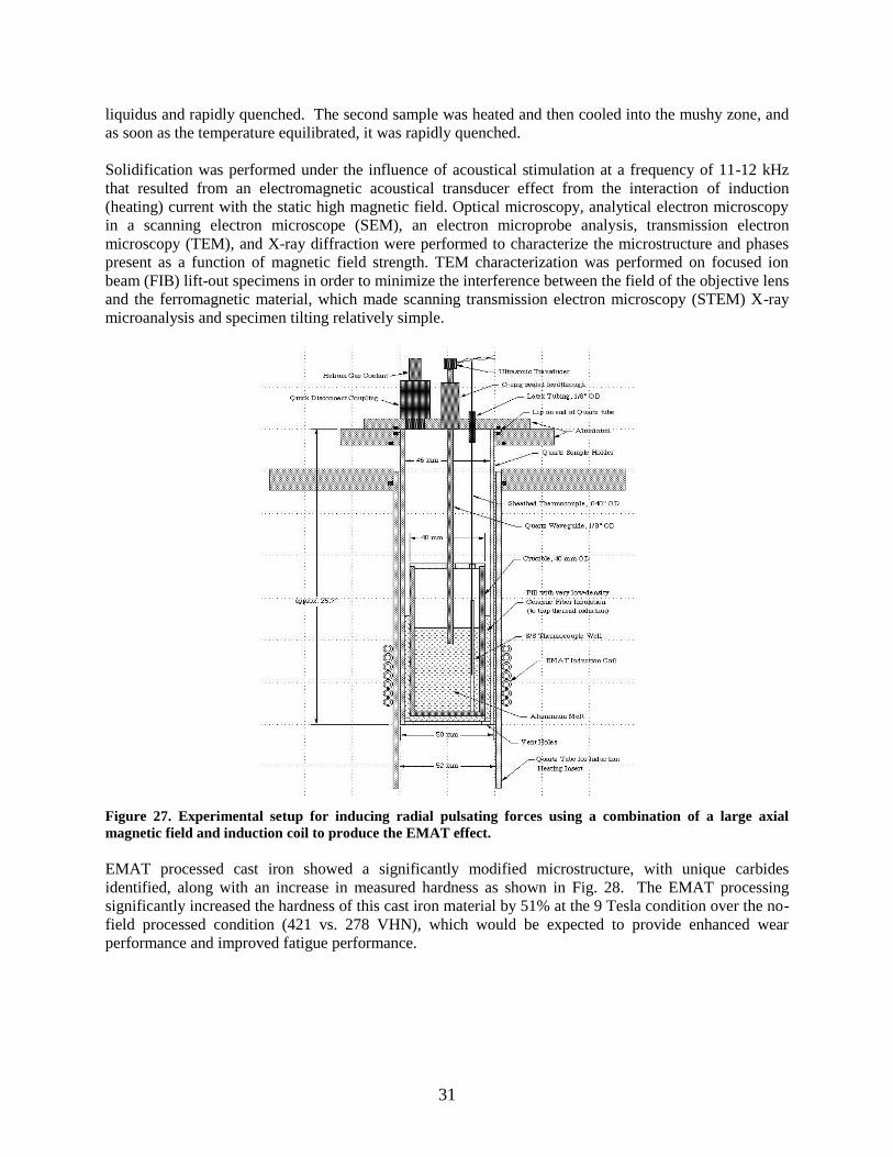
31
liquidus and rapidly quenched. The second sample was heated and then cooled into the mushy zone, and
as soon as the temperature equilibrated, it was rapidly quenched.
Solidification was performed under the influence of acoustical stimulation at a frequency of 11-12 kHz
that resulted from an electromagnetic acoustical transducer effect from the interaction of induction
(heating) current with the static high magnetic field. Optical microscopy, analytical electron microscopy
in a scanning electron microscope (SEM), an electron microprobe analysis, transmission electron
microscopy (TEM), and X-ray diffraction were performed to characterize the microstructure and phases
present as a function of magnetic field strength. TEM characterization was performed on focused ion
beam (FIB) lift-out specimens in order to minimize the interference between the field of the objective lens
and the ferromagnetic material, which made scanning transmission electron microscopy (STEM) X-ray
microanalysis and specimen tilting relatively simple.
Figure 27. Experimental setup for inducing radial pulsating forces using a combination of a large axial
magnetic field and induction coil to produce the EMAT effect.
EMAT processed cast iron showed a significantly modified microstructure, with unique carbides
identified, along with an increase in measured hardness as shown in Fig. 28. The EMAT processing
significantly increased the hardness of this cast iron material by 51% at the 9 Tesla condition over the no-
field processed condition (421 vs. 278 VHN), which would be expected to provide enhanced wear
performance and improved fatigue performance.
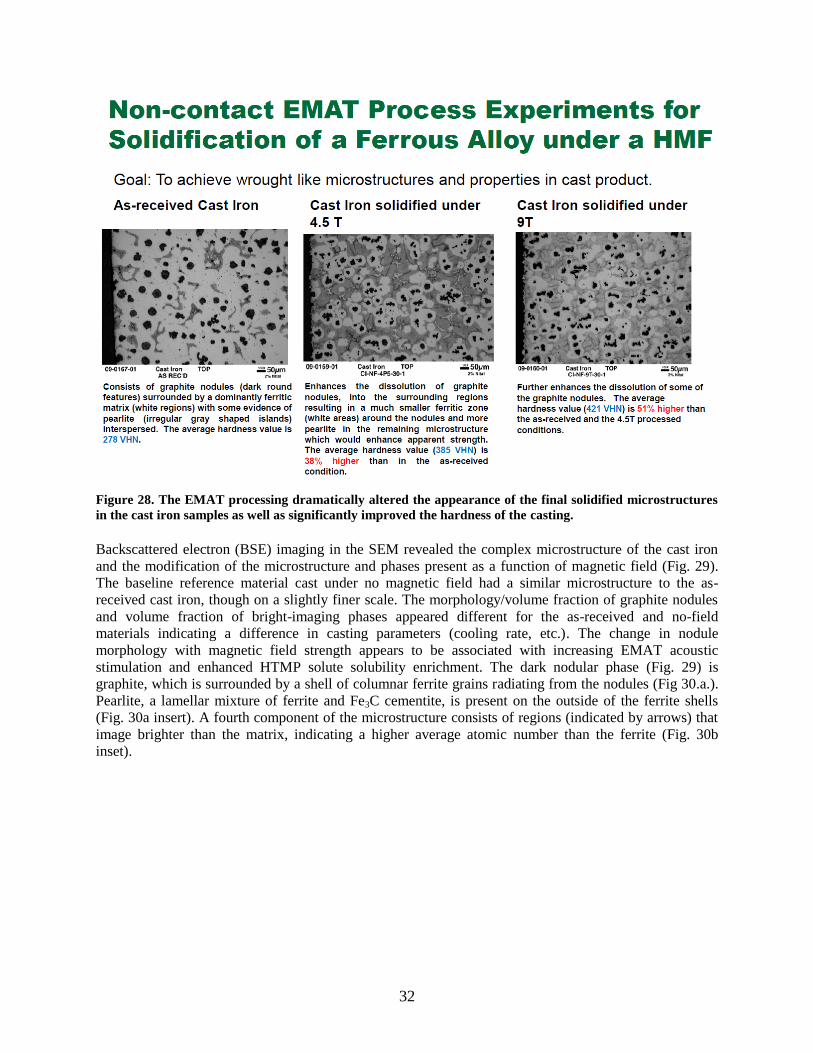
32
Figure 28. The EMAT processing dramatically altered the appearance of the final solidified microstructures
in the cast iron samples as well as significantly improved the hardness of the casting.
Backscattered electron (BSE) imaging in the SEM revealed the complex microstructure of the cast iron
and the modification of the microstructure and phases present as a function of magnetic field (Fig. 29).
The baseline reference material cast under no magnetic field had a similar microstructure to the as-
received cast iron, though on a slightly finer scale. The morphology/volume fraction of graphite nodules
and volume fraction of bright-imaging phases appeared different for the as-received and no-field
materials indicating a difference in casting parameters (cooling rate, etc.). The change in nodule
morphology with magnetic field strength appears to be associated with increasing EMAT acoustic
stimulation and enhanced HTMP solute solubility enrichment. The dark nodular phase (Fig. 29) is
graphite, which is surrounded by a shell of columnar ferrite grains radiating from the nodules (Fig 30.a.).
Pearlite, a lamellar mixture of ferrite and Fe3C cementite, is present on the outside of the ferrite shells
(Fig. 30a insert). A fourth component of the microstructure consists of regions (indicated by arrows) that
image brighter than the matrix, indicating a higher average atomic number than the ferrite (Fig. 30b
inset).
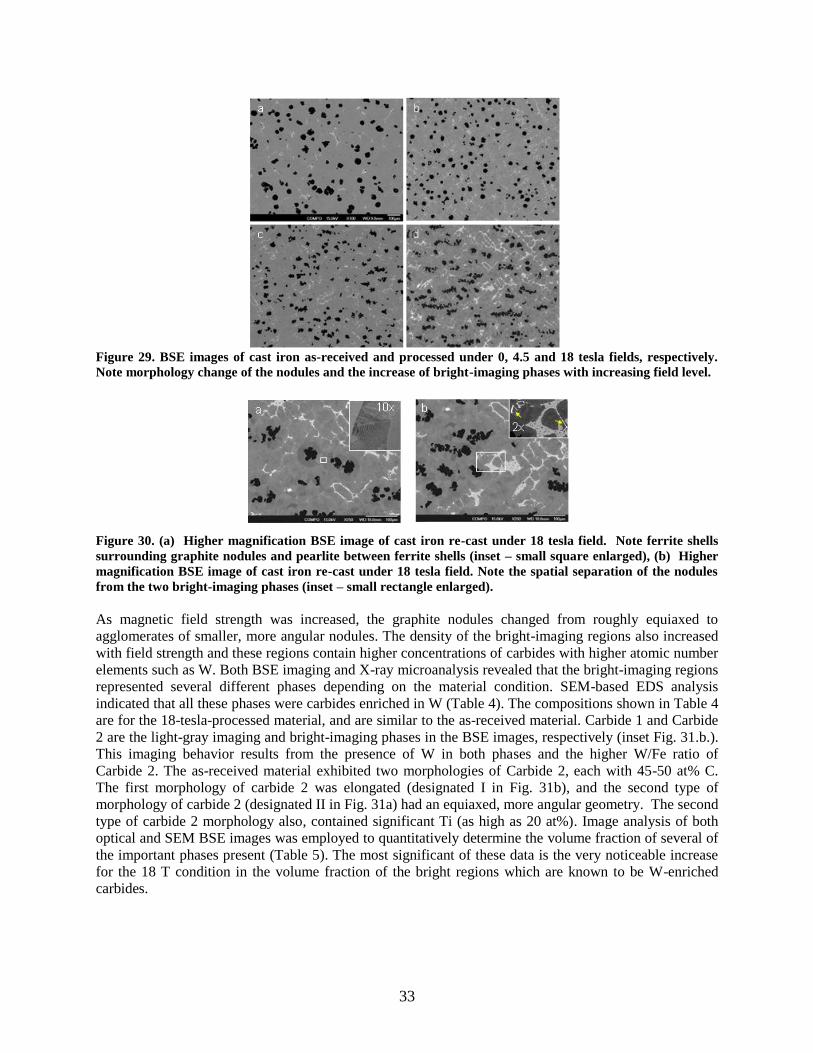
33
Figure 29. BSE images of cast iron as-received and processed under 0, 4.5 and 18 tesla fields, respectively.
Note morphology change of the nodules and the increase of bright-imaging phases with increasing field level.
Figure 30. (a) Higher magnification BSE image of cast iron re-cast under 18 tesla field. Note ferrite shells
surrounding graphite nodules and pearlite between ferrite shells (inset – small square enlarged), (b) Higher
magnification BSE image of cast iron re-cast under 18 tesla field. Note the spatial separation of the nodules
from the two bright-imaging phases (inset – small rectangle enlarged).
As magnetic field strength was increased, the graphite nodules changed from roughly equiaxed to
agglomerates of smaller, more angular nodules. The density of the bright-imaging regions also increased
with field strength and these regions contain higher concentrations of carbides with higher atomic number
elements such as W. Both BSE imaging and X-ray microanalysis revealed that the bright-imaging regions
represented several different phases depending on the material condition. SEM-based EDS analysis
indicated that all these phases were carbides enriched in W (Table 4). The compositions shown in Table 4
are for the 18-tesla-processed material, and are similar to the as-received material. Carbide 1 and Carbide
2 are the light-gray imaging and bright-imaging phases in the BSE images, respectively (inset Fig. 31.b.).
This imaging behavior results from the presence of W in both phases and the higher W/Fe ratio of
Carbide 2. The as-received material exhibited two morphologies of Carbide 2, each with 45-50 at% C.
The first morphology of carbide 2 was elongated (designated I in Fig. 31b), and the second type of
morphology of carbide 2 (designated II in Fig. 31a) had an equiaxed, more angular geometry. The second
type of carbide 2 morphology also, contained significant Ti (as high as 20 at%). Image analysis of both
optical and SEM BSE images was employed to quantitatively determine the volume fraction of several of
the important phases present (Table 5). The most significant of these data is the very noticeable increase
for the 18 T condition in the volume fraction of the bright regions which are known to be W-enriched
carbides.
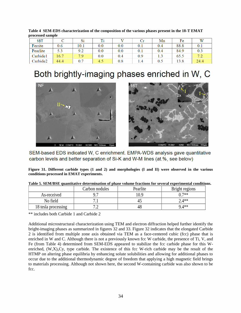
34
Table 4 SEM-EDS characterization of the composition of the various phases present in the 18-T EMAT
processed sample
Figure 31. Different carbide types (1 and 2) and morphologies (I and II) were observed in the various
conditions processed in EMAT experiments.
Table 5. SEM/BSE quantitative determination of phase volume fractions for several experimental conditions.
** includes both Carbide 1 and Carbide 2
Additional microstructural characterization using TEM and electron diffraction helped further identify the
bright-imaging phases as summarized in figures 32 and 33. Figure 32 indicates that the elongated Carbide
2 is identified from multiple zone axis obtained via TEM as a face-centered cubic (fcc) phase that is
enriched in W and C. Although there is not a previously known fcc W carbide, the presence of Ti, V, and
Fe (from Table 4) determined from SEM-EDS appeared to stabilize the fcc carbide phase for this W-
enriched, (W,X)xCy, type carbide. The existence of this fcc W-rich carbide may be the result of the
HTMP on altering phase equilibria by enhancing solute solubilities and allowing for additional phases to
occur due to the additional thermodynamic degree of freedom that applying a high magnetic field brings
to materials processing. Although not shown here, the second W-containing carbide was also shown to be
fcc.
Carbon nodules Pearlite Bright regions
As-received 9.7 10.9 0.7**
No field 7.1 45 2.4**
18 tesla processing 7.2 48 9.4**
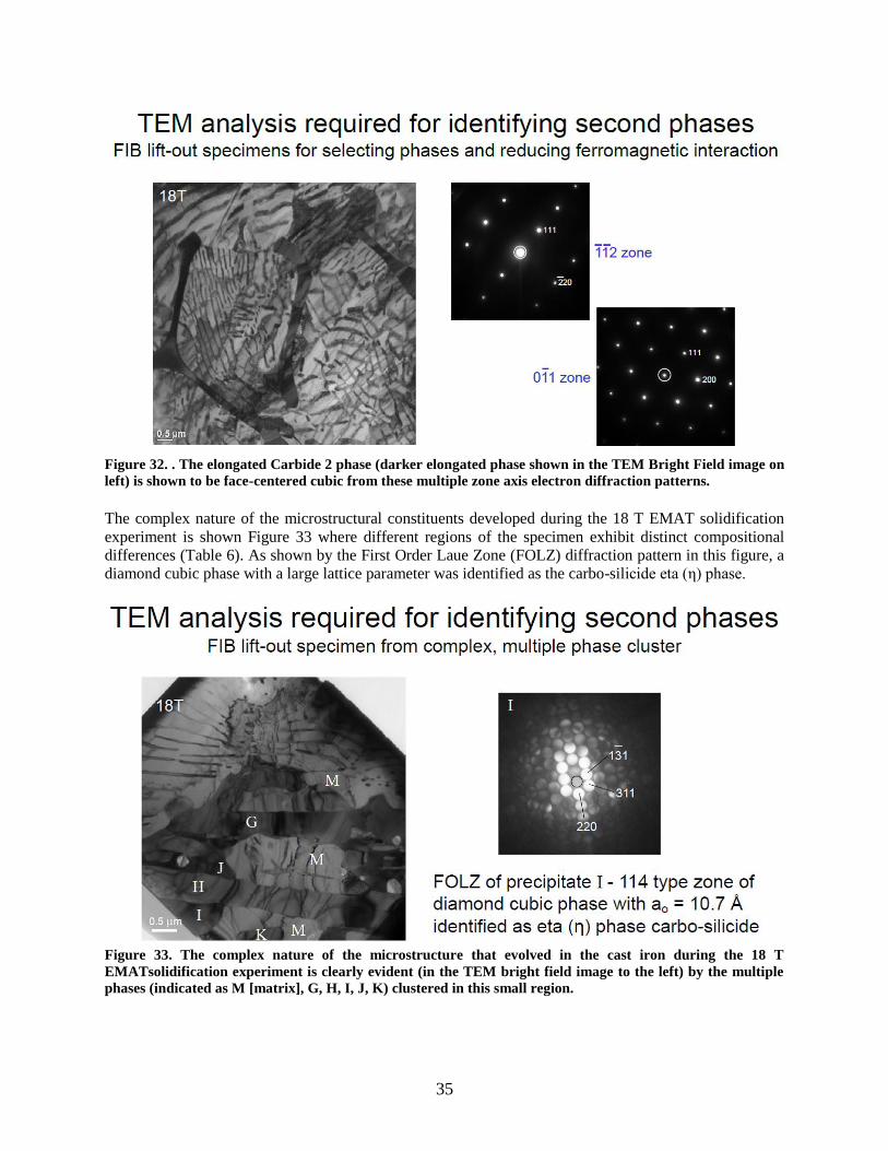
35
Figure 32. . The elongated Carbide 2 phase (darker elongated phase shown in the TEM Bright Field image on
left) is shown to be face-centered cubic from these multiple zone axis electron diffraction patterns.
The complex nature of the microstructural constituents developed during the 18 T EMAT solidification
experiment is shown Figure 33 where different regions of the specimen exhibit distinct compositional
differences (Table 6). As shown by the First Order Laue Zone (FOLZ) diffraction pattern in this figure, a
diamond cubic phase with a large lattice parameter was identified as the carbo-silicide eta (η) phase.
Figure 33. The complex nature of the microstructure that evolved in the cast iron during the 18 T
EMATsolidification experiment is clearly evident (in the TEM bright field image to the left) by the multiple
phases (indicated as M [matrix], G, H, I, J, K) clustered in this small region.
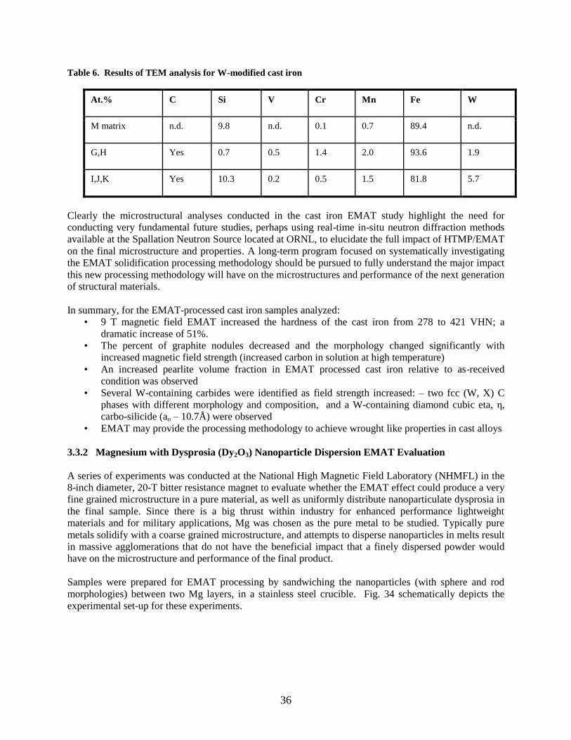
36
Table 6. Results of TEM analysis for W-modified cast iron
At.% C Si V Cr Mn Fe W
M matrix n.d. 9.8 n.d. 0.1 0.7 89.4 n.d.
G,H Yes 0.7 0.5 1.4 2.0 93.6 1.9
I,J,K Yes 10.3 0.2 0.5 1.5 81.8 5.7
Clearly the microstructural analyses conducted in the cast iron EMAT study highlight the need for
conducting very fundamental future studies, perhaps using real-time in-situ neutron diffraction methods
available at the Spallation Neutron Source located at ORNL, to elucidate the full impact of HTMP/EMAT
on the final microstructure and properties. A long-term program focused on systematically investigating
the EMAT solidification processing methodology should be pursued to fully understand the major impact
this new processing methodology will have on the microstructures and performance of the next generation
of structural materials.
In summary, for the EMAT-processed cast iron samples analyzed:
• 9 T magnetic field EMAT increased the hardness of the cast iron from 278 to 421 VHN; a
dramatic increase of 51%.
• The percent of graphite nodules decreased and the morphology changed significantly with
increased magnetic field strength (increased carbon in solution at high temperature)
• An increased pearlite volume fraction in EMAT processed cast iron relative to as-received
condition was observed
• Several W-containing carbides were identified as field strength increased: – two fcc (W, X) C
phases with different morphology and composition, and a W-containing diamond cubic eta, η,
carbo-silicide (ao – 10.7Å) were observed
• EMAT may provide the processing methodology to achieve wrought like properties in cast alloys
3.3.2 Magnesium with Dysprosia (Dy2O3) Nanoparticle Dispersion EMAT Evaluation
A series of experiments was conducted at the National High Magnetic Field Laboratory (NHMFL) in the
8-inch diameter, 20-T bitter resistance magnet to evaluate whether the EMAT effect could produce a very
fine grained microstructure in a pure material, as well as uniformly distribute nanoparticulate dysprosia in
the final sample. Since there is a big thrust within industry for enhanced performance lightweight
materials and for military applications, Mg was chosen as the pure metal to be studied. Typically pure
metals solidify with a coarse grained microstructure, and attempts to disperse nanoparticles in melts result
in massive agglomerations that do not have the beneficial impact that a finely dispersed powder would
have on the microstructure and performance of the final product.
Samples were prepared for EMAT processing by sandwiching the nanoparticles (with sphere and rod
morphologies) between two Mg layers, in a stainless steel crucible. Fig. 34 schematically depicts the
experimental set-up for these experiments.

37
Figure 34. Schematic representing the experimental set-up for EMAT processing of pure Mg with
nanoparticles incorporated into the set-up to achieve nano-particle dispersion.
The cast Mg sections were pressed into the stainless steel crucible, and all casting was performed in a
glove box under an inert argon atmosphere. The goal of these experiments was to incorporate the
nanoparticles Dy2O3 in Mg, as a nano dispersion using EMAT processing, avoiding agglomeration.
EMAT processing was conducted on two samples. Both samples were purged under Ar gas for 30
minutes; then the magnetic field was ramped up to 20T. Once at field, the EMAT processing was
conducted by applying induction heat at ~10 kHz for a given power level. Once the Mg fully melted, as
evident by the completion of the thermal arrest, the samples were rapidly cooled using a He-gas quench.
Upon examination of the first EMAT processed sample, it was determined that the EMAT exposure for
Sample 1 was excessive. Sample 2 was processed using a lower EMAT power level. Figures 35 and 36
show photos of the Mg sample contained in the stainless steel crucible after thermo-magnetic processing.
The white strips are present help to provide a snug fit inside the quartz sample tube during the EMAT
processing. The tube extending out of the crucible is for the thermocouple.
Figure 35. Mg sample stainless steel crucible after thermo-magnetic processing.

38
Figure 36. A pure Mg samples is shown in the stainless steel crucible prior to the EMAT experiments (a) the
sample prior to placement of the loose nanoparticles in the assembly and (b) the final assembly with a
containment lid on top of the crucible in the quartz, inert atmosphere experiment tube.
The Mg EMAT experiments were extremely successful in meeting the goals of grain refinement and
uniform particle dispersion. Characterization results document that a nanocrystalline grain size was
developed in the Mg matrix and the dysprosium oxide nanospheres and nanorods (two separate
experiments) were very uniformly distributed throughout the casting with no significant evidence of
agglomeration.
Transmission electron microscopy of the samples revealed the uniform (non-agglomerated) dispersion of
the fine nanorods and nanospheres as shown in Figures 37.
Figure 37. Transmission electron microscopy micrographs of the uniformly dispersed dysprosium oxide.
A cross section of the EMAT processed sample was prepared using a focused ion beam method (FIB) so
that very thin foils could be obtained that would be suitable samples for STEM analyses. The initial FIB
sample can be seen in Figure 38 in the upper left hand corner. The sample was imaged using both BF
(bright field) and DF (dark field) diffraction conditions which are visible in Figure 38. For this location
in the EMAT processed ingot, an extremely fine and uniform dispersion of the dysprosia nanoparticles is
evident as seen in the bottom two images of Figure 38. Figure 39 shows a second location in this sample
with comparable dispersions of the nanoparticles. Figures 40 and 41 show evidence of more agglomerated
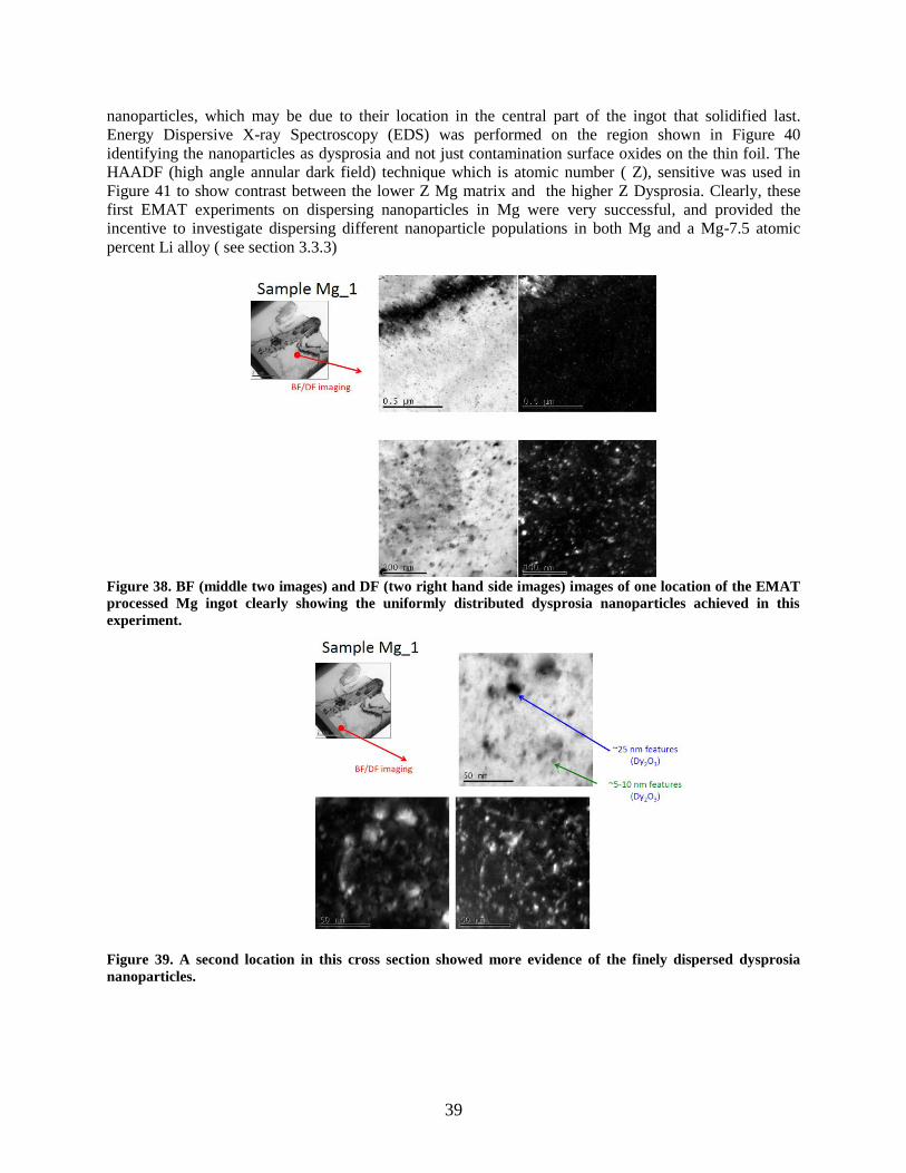
39
nanoparticles, which may be due to their location in the central part of the ingot that solidified last.
Energy Dispersive X-ray Spectroscopy (EDS) was performed on the region shown in Figure 40
identifying the nanoparticles as dysprosia and not just contamination surface oxides on the thin foil. The
HAADF (high angle annular dark field) technique which is atomic number ( Z), sensitive was used in
Figure 41 to show contrast between the lower Z Mg matrix and the higher Z Dysprosia. Clearly, these
first EMAT experiments on dispersing nanoparticles in Mg were very successful, and provided the
incentive to investigate dispersing different nanoparticle populations in both Mg and a Mg-7.5 atomic
percent Li alloy ( see section 3.3.3)
Figure 38. BF (middle two images) and DF (two right hand side images) images of one location of the EMAT
processed Mg ingot clearly showing the uniformly distributed dysprosia nanoparticles achieved in this
experiment.
Figure 39. A second location in this cross section showed more evidence of the finely dispersed dysprosia
nanoparticles.
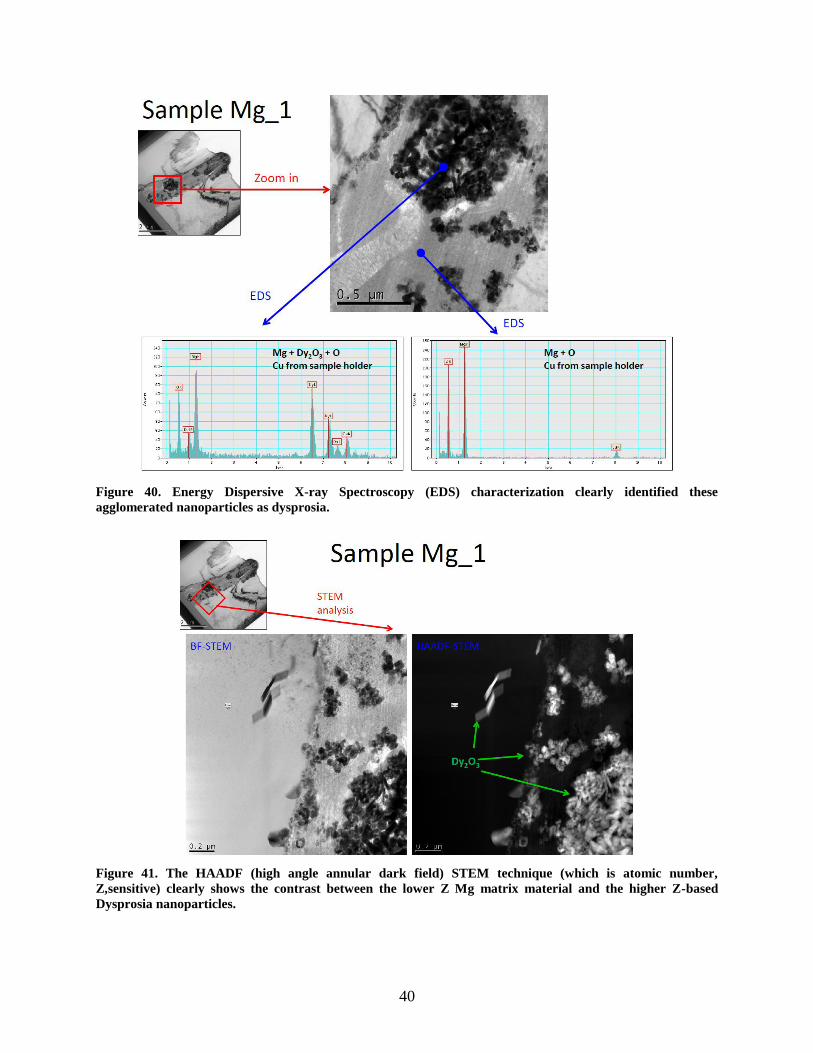
40
Figure 40. Energy Dispersive X-ray Spectroscopy (EDS) characterization clearly identified these
agglomerated nanoparticles as dysprosia.
Figure 41. The HAADF (high angle annular dark field) STEM technique (which is atomic number,
Z,sensitive) clearly shows the contrast between the lower Z Mg matrix material and the higher Z-based
Dysprosia nanoparticles.
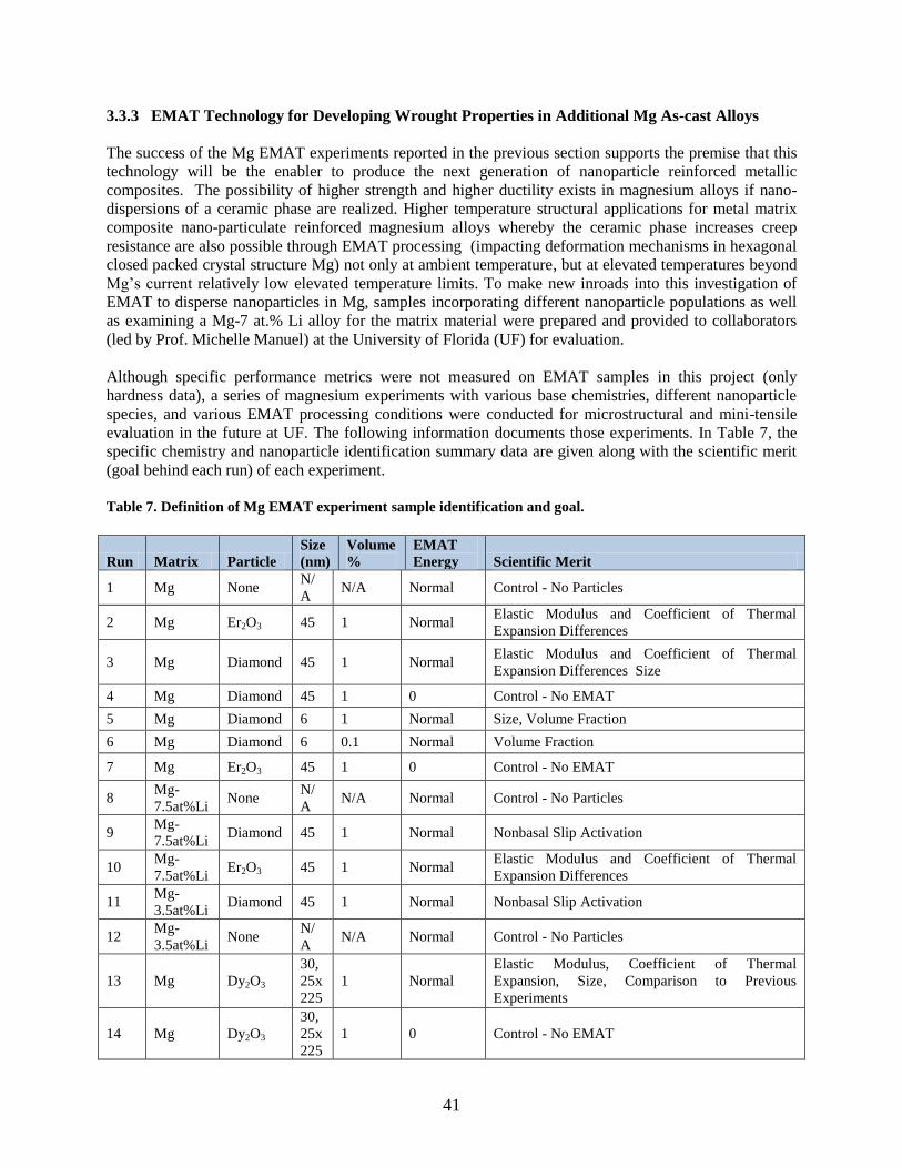
41
3.3.3 EMAT Technology for Developing Wrought Properties in Additional Mg As-cast Alloys
The success of the Mg EMAT experiments reported in the previous section supports the premise that this
technology will be the enabler to produce the next generation of nanoparticle reinforced metallic
composites. The possibility of higher strength and higher ductility exists in magnesium alloys if nano-
dispersions of a ceramic phase are realized. Higher temperature structural applications for metal matrix
composite nano-particulate reinforced magnesium alloys whereby the ceramic phase increases creep
resistance are also possible through EMAT processing (impacting deformation mechanisms in hexagonal
closed packed crystal structure Mg) not only at ambient temperature, but at elevated temperatures beyond
Mg’s current relatively low elevated temperature limits. To make new inroads into this investigation of
EMAT to disperse nanoparticles in Mg, samples incorporating different nanoparticle populations as well
as examining a Mg-7 at.% Li alloy for the matrix material were prepared and provided to collaborators
(led by Prof. Michelle Manuel) at the University of Florida (UF) for evaluation.
Although specific performance metrics were not measured on EMAT samples in this project (only
hardness data), a series of magnesium experiments with various base chemistries, different nanoparticle
species, and various EMAT processing conditions were conducted for microstructural and mini-tensile
evaluation in the future at UF. The following information documents those experiments. In Table 7, the
specific chemistry and nanoparticle identification summary data are given along with the scientific merit
(goal behind each run) of each experiment.
Table 7. Definition of Mg EMAT experiment sample identification and goal.
Run Matrix Particle
Size
(nm)
Volume
%
EMAT
Energy Scientific Merit
1 Mg None N/
A N/A Normal Control - No Particles
2 Mg Er2O3 45 1 Normal Elastic Modulus and Coefficient of Thermal
Expansion Differences
3 Mg Diamond 45 1 Normal Elastic Modulus and Coefficient of Thermal
Expansion Differences Size
4 Mg Diamond 45 1 0 Control - No EMAT
5 Mg Diamond 6 1 Normal Size, Volume Fraction
6 Mg Diamond 6 0.1 Normal Volume Fraction
7 Mg Er2O3 45 1 0 Control - No EMAT
8 Mg-
7.5at%Li None
N/
A N/A Normal Control - No Particles
9 Mg-
7.5at%Li Diamond 45 1 Normal Nonbasal Slip Activation
10 Mg-
7.5at%Li Er2O3 45 1 Normal
Elastic Modulus and Coefficient of Thermal
Expansion Differences
11 Mg-
3.5at%Li Diamond 45 1 Normal Nonbasal Slip Activation
12 Mg-
3.5at%Li None
N/
A N/A Normal Control - No Particles
13 Mg Dy2O3
30,
25x
225
1 Normal
Elastic Modulus, Coefficient of Thermal
Expansion, Size, Comparison to Previous
Experiments
14 Mg Dy2O3
30,
25x
225
1 0 Control - No EMAT
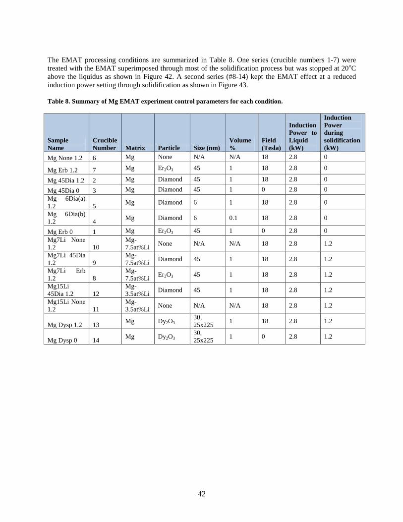
42
The EMAT processing conditions are summarized in Table 8. One series (crucible numbers 1-7) were
treated with the EMAT superimposed through most of the solidification process but was stopped at 20oC
above the liquidus as shown in Figure 42. A second series (#8-14) kept the EMAT effect at a reduced
induction power setting through solidification as shown in Figure 43.
Table 8. Summary of Mg EMAT experiment control parameters for each condition.
Sample
Name
Crucible
Number Matrix Particle Size (nm)
Volume
%
Field
(Tesla)
Induction
Power to
Liquid
(kW)
Induction
Power
during
solidification
(kW)
Mg None 1.2 6 Mg None N/A N/A 18 2.8 0
Mg Erb 1.2 7 Mg Er2O3 45 1 18 2.8 0
Mg 45Dia 1.2 2 Mg Diamond 45 1 18 2.8 0
Mg 45Dia 0 3 Mg Diamond 45 1 0 2.8 0
Mg 6Dia(a)
1.2 5 Mg Diamond 6 1 18 2.8 0
Mg 6Dia(b)
1.2 4 Mg Diamond 6 0.1 18 2.8 0
Mg Erb 0 1 Mg Er2O3 45 1 0 2.8 0
Mg7Li None
1.2 10
Mg-
7.5at%Li None N/A N/A 18 2.8 1.2
Mg7Li 45Dia
1.2 9
Mg-
7.5at%Li Diamond 45 1 18 2.8 1.2
Mg7Li Erb
1.2 8
Mg-
7.5at%Li Er2O3 45 1 18 2.8 1.2
Mg15Li
45Dia 1.2 12
Mg-
3.5at%Li Diamond 45 1 18 2.8 1.2
Mg15Li None
1.2 11
Mg-
3.5at%Li None N/A N/A 18 2.8 1.2
Mg Dysp 1.2 13 Mg Dy2O3
30,
25x225 1 18 2.8 1.2
Mg Dysp 0 14 Mg Dy2O3
30,
25x225 1 0 2.8 1.2

43
Figure 42. One series of EMAT experiments stopped the EMAT effect by turning off the induction power.
Figure 43. The second series of EMAT experiments continued the EMAT at a reduced induction power
supply setting until solidification was completed.
By the conclusion of this project, these samples had only been cut in half using an electro discharge
machining (EDM) process. The initial evaluation of appearance suggests that all of the samples solidified
with high integrity, with the only obvious voids being associated with the stainless steel thermocouple
wells that were inserted into the samples (via a pre-drilled hole). Figure 44 shows these samples together.
Figure 45 shows a typical solidified sample. University of Florida collaborators led by Prof. Michelle
Manuel will fabricate small test coupons and TEM samples from these small ingots. UF will report these
data to ORNL, and incorporate results in a coauthored refereed literature publication to document the
experiments outside of this report.
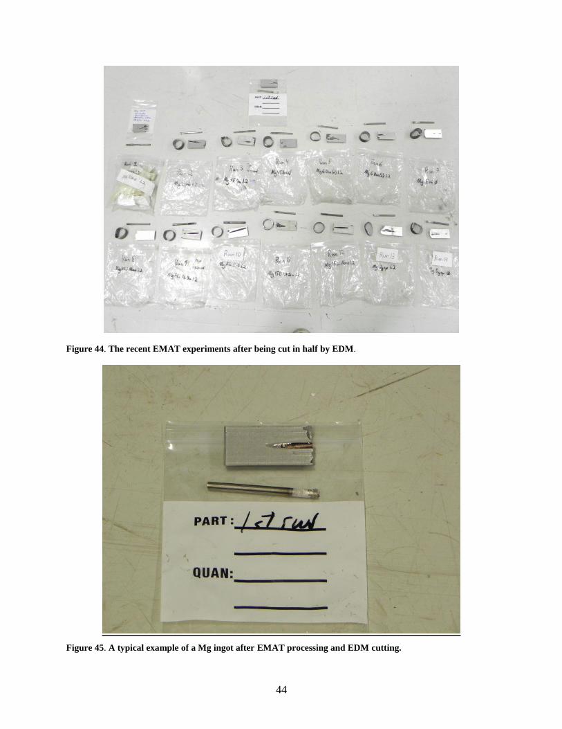
44
Figure 44. The recent EMAT experiments after being cut in half by EDM.
Figure 45. A typical example of a Mg ingot after EMAT processing and EDM cutting.
45
3.4 FACILITATION OF HTMP/EMAT TECHNOLOGY COMMERCIALIZATION
During this project, Ajax-Tocco, AMI and ORNL agreed on the final specifications (e.g., H-field strength,
uniform field length, extraction forces, rotational effects during quenching/heating, etc.) and finalized the
design for a magnet system which was procured with outside funding. This magnet is an 8-inch diameter
bore system that will allow both dual frequency thermomagnetic field processing, as well as an integrated
heating/quench capability that can accommodate some larger industrial scale applications. This magnet
was delivered in the FY 2011. This magnet represents an intermediate, but important step for AMI in that
it incorporates both a large magnetic field (9T) and a large (8-inch) diameter bore magnet with a more
energy efficient re-condensing style cryocooler system that significantly reduces (actually eliminates) the
consumption of liquid cryogens previously required by superconducting magnets in earlier designs. This
knowledge and the benefits gained through the development of this magnet provide a strong experience
base and provide valuable leverage for the design of future industrial scale magnets that will be needed to
commercial this HTMP technology.
Previous experience with conventionally cooled superconducting systems identified the effort and
expense of regularly replacing liquid cryogens as a major barrier to commercialization. Recondensing
cryocooler systems for liquid helium were identified as a priority for commercial designs to enable near
lifetime operation with initial loading of liquid cryogens.
A second potential barrier to commercialization was identified relating to the EMAT effect. When lower
frequency was employed at relatively modest (>2 KW) induction power levels, the EMAT effect would
cause the superconducting magnet to quench, lose all of its cryogens and no longer be superconducting.
This event would result in almost a two-week down time to get the magnet refilled with cryogens and
back to persistent mode at maximum magnetic field strength. Therefore, AMI developed possible
solutions to mitigate this weakness, then, engaged NHMFL magnet design experts to review and confirm
that incorporating the solutions that AMI proposed for the 9T, ~8inch magnet. AMI implemented several
proprietary internal system design changes to make the superconducting magnet resistant to EMAT-
induced quenches. In addition, critical to the final design of the superconducting magnet system coupled
with a 220 KW induction heating power supply/induction coil design was evaluating overall system
design requirements factoring in the following:
1) Induction Coil Survival at 200 kW in 9T Magnetic Field
2) Electromagnetic JxB Forces Acting on the Induction Heating Coil
3) Static Pressure and Hoop Stress in a 2.75” Diameter Coil for DC Current
4) Inertial-Mass Limited Radial Acceleration and Radial Strain above 10 kHz
5) Resonant Frequency of the Induction Coil for the Radially Symmetric Mode
6) Resonant Frequency of the EMAT Barrier Tube
These are addressed specifically below.
3.4.1 Magnet Design Considerations
3.4.1.1 Induction coil survival at 200 kW in 9T magnetic field
For a helical coil that is rigidly pinned/secured at both ends, or where adjacent turns are rigidly tied
together, the maximum stress for low frequency, or DC, operation can be estimated by considering the
effective pressure developed by the Lorentz JxB force, and the associated hoop stress. At higher
frequencies where the resulting radial motion of current carrying elements is limited by the inertial mass
of the copper, the radial strain is reduced, and the stress is reduced accordingly.
46
For a helical coil that is not rigidly tied down at both ends, the hoop stress will act to unwind the coil
along the helical direction. In addition to the inertial mass limited motion in the radial direction, the ends
of each turn are held in place by the inertia provided by the mass of adjacent turns, which acts not in the
radial direction but along the length of the helical winding. The net result is a radial expansion coupled
with a helically directed motion that propagates to the ends of the coils, such that a 10 µm radial motion
translates into up to (2p)(10)(12)/2 = 380 µm movement of the both ends of the helix, in the helical
direction. The maximum stress that develops will be less than that for a helix that is pinned at both ends.
The radial motion does includes a component that is related to hoop stress, which dominates at high
frequency, but also includes a component related to the helical winding/unwinding motion in the helical
direction, and the free movement at both ends, that dominates the response at low frequency.
To address the range of possibilities, and the possible range of frequencies, two different types estimates
for the coil strain were examined, 1) based on the hoop stress for a coil that is pinned at both ends, in the
low frequency and/or DC limit, and 2) the inertial-mass-limited strain that addresses the high frequency
response, and provides the first step in understanding the case where the coil is free standing and is not
significantly constrained at either end.
In addition, mechanical resonances must be considered and taken into account. If the induction coil is
driven at a frequency near its mechanical resonance, the strain could be enhanced by an order of
magnitude or more. In addition, one must also be aware of the radially symmetric resonance of the
sacrificial liner (EMAT barrier) tube, which is driven by the Lorentz JxB force arising from the induction
current induced on the inner surface of the tube by the external return flux of the induction coil.
Based on the present design, the diameter of the induction coil has a diameter of 2.5” ID/ 3.0” OD, for a
mean diameter of 2.745” (70 mm). It is assumed that the induction coil will be fabricated from ¼” soft
copper tubing having a wall thickness of 0.032” (0.8 mm). For 200 kW operation, it is assumed that the
coil current has a peak value (amplitude) of 2000A (1410Arms), and that the induction coil is located in a
uniform axial magnetic field of 9 Tesla.
3.4.1.2 Electromagnetic JxB forces acting on the induction heating coil
The 9 Tesla magnetic field is oriented along the axis of the solenoid. The predominantly radial force
resulting from the cross product of the azimuthally directed coil current and the axial 9 Tesla B-field is
then given by:
where Fr is the peak radial JxB force per unit length of conductor.
3.4.1.3 Static pressure and hoop stress in a 2.75” diameter coil for DC current
Assume that the coil is not helical in shape, but rather each turn is a ring that rigidly connects on itself.
[Alternatively, assume that both ends of a helical coil are rigidly pinned in place.] If a large number of
rings are lined up side-by-side to form a continuous cylinder, then the Lorentz force constitutes a radial
pressure, and the hoop stress can be estimated directly.
Since the Lorentz force on each ¼” wide turn is 18 newtons per mm of length, or equivalently (18 N/mm)
(0.2248 lb/N)(25.4mm/in) = 102.8 lb/in, the pressure, P = F/A, is then 102.8/(0.25 sq in) = 411 psi, as the
force on each 1” length is acting on an area ¼” by 1” in area, or 0.25 sq in. [ Or equivalently, one could
consider 4 adjacent conductor element each with a 1” length, in which case the force on a 1”x1” area is
4(102.8 lb/in)(1”) = 411 lbs.]
Fr I Bz (2000A)(9T) 18,000N /m 18N/mm
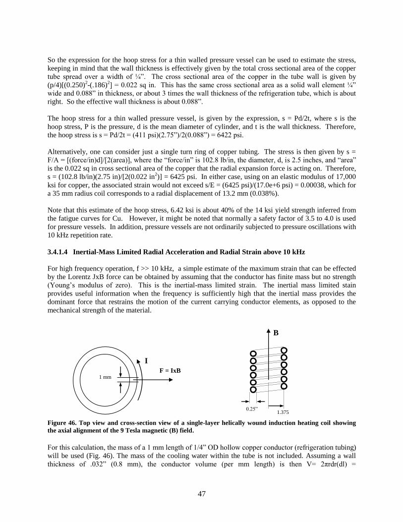
47
So the expression for the hoop stress for a thin walled pressure vessel can be used to estimate the stress,
keeping in mind that the wall thickness is effectively given by the total cross sectional area of the copper
tube spread over a width of ¼”. The cross sectional area of the copper in the tube wall is given by
(p/4)[(0.250)2-(.186)
2] = 0.022 sq in. This has the same cross sectional area as a solid wall element ¼”
wide and 0.088” in thickness, or about 3 times the wall thickness of the refrigeration tube, which is about
right. So the effective wall thickness is about 0.088”.
The hoop stress for a thin walled pressure vessel, is given by the expression, s = Pd/2t, where s is the
hoop stress, P is the pressure, d is the mean diameter of cylinder, and t is the wall thickness. Therefore,
the hoop stress is s = Pd/2t = (411 psi)(2.75”)/2(0.088”) = 6422 psi.
Alternatively, one can consider just a single turn ring of copper tubing. The stress is then given by s =
F/A = [(force/in)d]/[2(area)], where the “force/in” is 102.8 lb/in, the diameter, d, is 2.5 inches, and “area”
is the 0.022 sq in cross sectional area of the copper that the radial expansion force is acting on. Therefore,
s = (102.8 lb/in)(2.75 in)/[2(0.022 in2)] = 6425 psi. In either case, using on an elastic modulus of 17,000
ksi for copper, the associated strain would not exceed s/E = (6425 psi)/(17.0e+6 psi) = 0.00038, which for
a 35 mm radius coil corresponds to a radial displacement of 13.2 mm (0.038%).
Note that this estimate of the hoop stress, 6.42 ksi is about 40% of the 14 ksi yield strength inferred from
the fatigue curves for Cu. However, it might be noted that normally a safety factor of 3.5 to 4.0 is used
for pressure vessels. In addition, pressure vessels are not ordinarily subjected to pressure oscillations with
10 kHz repetition rate.
3.4.1.4 Inertial-Mass Limited Radial Acceleration and Radial Strain above 10 kHz
For high frequency operation, f >> 10 kHz, a simple estimate of the maximum strain that can be effected
by the Lorentz JxB force can be obtained by assuming that the conductor has finite mass but no strength
(Young’s modulus of zero). This is the inertial-mass limited strain. The inertial mass limited stain
provides useful information when the frequency is sufficiently high that the inertial mass provides the
dominant force that restrains the motion of the current carrying conductor elements, as opposed to the
mechanical strength of the material.
Figure 46. Top view and cross-section view of a single-layer helically wound induction heating coil showing
the axial alignment of the 9 Tesla magnetic (B) field.
For this calculation, the mass of a 1 mm length of 1/4” OD hollow copper conductor (refrigeration tubing)
will be used (Fig. 46). The mass of the cooling water within the tube is not included. Assuming a wall
thickness of .032” (0.8 mm), the conductor volume (per mm length) is then V= 2πrdr(dl) =
1 mm
I
F = IxB
1.375
”
0.25”
B
48
2π(2.8mm)(0.8mm)(1.0) = 14.07 mm3. Based on the mass density of copper, 8.94 gm/cc, the mass of this
length of conductor element is then:
This is the mass per millimeter length of the ¼” OD conductor element. The peak radial acceleration on
this 1 mm conductor element due to the electromagnetic JxB force is then given by:
Integrating the time dependent acceleration, a(t) = aosin(πt), to obtain the velocity, v(t),
Integrating the time dependent velocity, v(t) = vocos(πt), to obtain the displacement, d(t),
The maximum (peak) velocity of the conductor element at 20 kHz is therefore
and the maximum (peak) displacement is given by
For the solenoid-shaped induction heating coil with a nominal radius of 35 mm (1.375”), this represents a
maximum normalized dimensional change (strain) of
in the radial direction, alternately stretching and compressing the individual turns of copper coil. This is
comparable to the strain calculated from the expected hoop stress for static, or low frequency conditions.
Therefore, for the frequency range below 20 kHz, including 10 kHz operation, the expected strain would
be similar to that inferred from the static pressure and hoop stress for DC current operation, whereas at
higher frequencies the strain falls off as the reciprocal of the frequency-squared. For example, if the
frequency were doubled from 20 kHz to 40 kHz, then the peak velocity would be reduced by a factor of
two to 0.57 m/s, and the peak displacement would be reduced by a factor of four to just 2.3 µm,
corresponding to a strain of 0.65x10⁻⁴
(0.0065%). Near the transition frequency of 20 kHz, both the hoop
stress and the inertial mass act jointly to determine the strain. Based on these considerations alone, the
frequency dependence of the expected strain is approximately as shown in Fig. 47.
m V (.00894g /mm3 )(14.1mm3) 0.126g 1.26x10⁴ kg
ao F
m(18N /mm)(1.0mm)
1.26x10⁴ kg14.3x104m /sec2
v(t) a( t)dt ao sin(t)dt ao
cos(t)
d(t) v(t)dt vo cos(t)dt vo
sin(t)
ao
2sin(t)
vo ao
2f14.3x104m/sec2
2 (20kHz)1.14m/sec
do ao
(2f )214.3x10⁴m/sec2
[2(20kHz)]2 9.1x10⁶m 9.1m
r
r9.06m
35mm 2.59x10⁴ (0.026%)
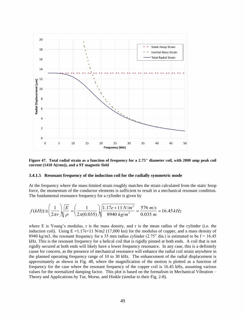
49
Figure 47. Total radial strain as a function of frequency for a 2.75" diameter coil, with 2000 amp peak coil
current (1410 A(rms)), and a 9T magnetic field
3.4.1.5 Resonant frequency of the induction coil for the radially symmetric mode
At the frequency where the mass-limited strain roughly matches the strain calculated from the static hoop
force, the momentum of the conductor elements is sufficient to result in a mechanical resonant condition.
The fundamental resonance frequency for a cylinder is given by
where E is Young’s modulus, r is the mass density, and r is the mean radius of the cylinder (i.e. the
induction coil). Using E =1.17e+11 N/m2 (17,000 ksi) for the modulus of copper, and a mass density of
8940 kg/m3, the resonant frequency for a 35 mm radius cylinder (2.75” dia.) is estimated to be f = 16.45
kHz. This is the resonant frequency for a helical coil that is rigidly pinned at both ends. A coil that is not
rigidly secured at both ends will likely have a lower frequency resonance. In any case, this is a definitely
cause for concern, as the presence of mechanical resonance will enhance the radial coil strain anywhere in
the planned operating frequency range of 10 to 30 kHz. The enhancement of the radial displacement is
approximately as shown in Fig. 48, where the magnification of the motion is plotted as a function of
frequency for the case where the resonant frequency of the copper coil is 16.45 kHz, assuming various
values for the normalized damping factor. This plot is based on the formalism in Mechanical Vibration –
Theory and Applications by Tse, Morse, and Hinkle (similar to their Fig. 2-8).
f (kHz) 1
2r
E
1
2(0.035)
1.17e 11N /m2
8940 kg/m3576 m/s
0.035 m16.45kHz
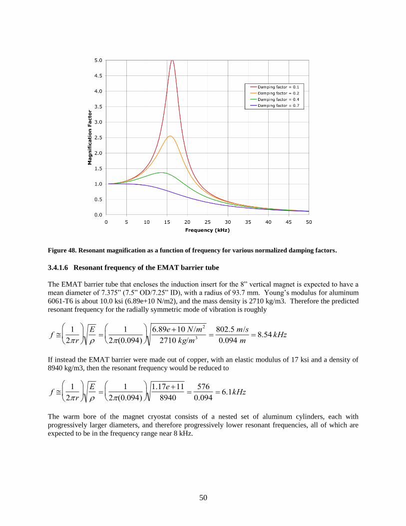
50
Figure 48. Resonant magnification as a function of frequency for various normalized damping factors.
3.4.1.6 Resonant frequency of the EMAT barrier tube
The EMAT barrier tube that encloses the induction insert for the 8” vertical magnet is expected to have a
mean diameter of 7.375” (7.5” OD/7.25” ID), with a radius of 93.7 mm. Young’s modulus for aluminum
6061-T6 is about 10.0 ksi (6.89e+10 N/m2), and the mass density is 2710 kg/m3. Therefore the predicted
resonant frequency for the radially symmetric mode of vibration is roughly
If instead the EMAT barrier were made out of copper, with an elastic modulus of 17 ksi and a density of
8940 kg/m3, then the resonant frequency would be reduced to
The warm bore of the magnet cryostat consists of a nested set of aluminum cylinders, each with
progressively larger diameters, and therefore progressively lower resonant frequencies, all of which are
expected to be in the frequency range near 8 kHz.
f 1
2r
E
1
2(0.094)
6.89e 10 N /m2
2710 kg/m3802.5 m/s
0.094 m 8.54 kHz
f 1
2r
E
1
2(0.094)
1.17e 11
8940576
0.094 6.1kHz
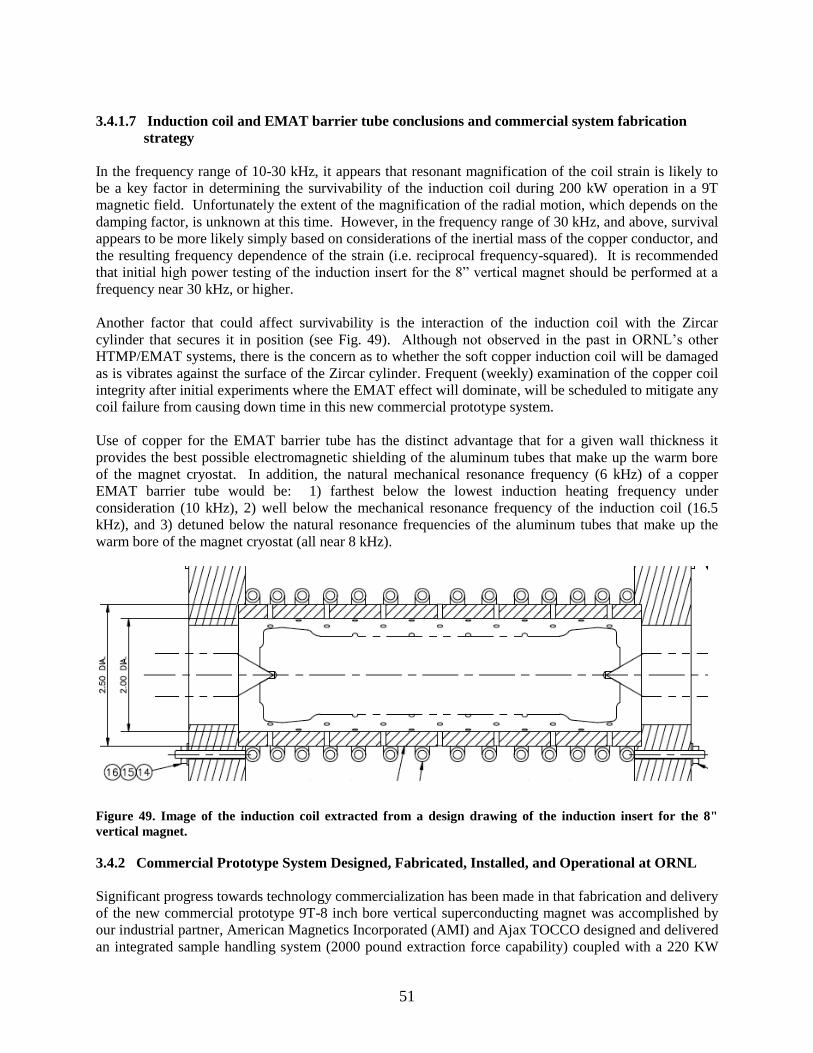
51
3.4.1.7 Induction coil and EMAT barrier tube conclusions and commercial system fabrication
strategy
In the frequency range of 10-30 kHz, it appears that resonant magnification of the coil strain is likely to
be a key factor in determining the survivability of the induction coil during 200 kW operation in a 9T
magnetic field. Unfortunately the extent of the magnification of the radial motion, which depends on the
damping factor, is unknown at this time. However, in the frequency range of 30 kHz, and above, survival
appears to be more likely simply based on considerations of the inertial mass of the copper conductor, and
the resulting frequency dependence of the strain (i.e. reciprocal frequency-squared). It is recommended
that initial high power testing of the induction insert for the 8” vertical magnet should be performed at a
frequency near 30 kHz, or higher.
Another factor that could affect survivability is the interaction of the induction coil with the Zircar
cylinder that secures it in position (see Fig. 49). Although not observed in the past in ORNL’s other
HTMP/EMAT systems, there is the concern as to whether the soft copper induction coil will be damaged
as is vibrates against the surface of the Zircar cylinder. Frequent (weekly) examination of the copper coil
integrity after initial experiments where the EMAT effect will dominate, will be scheduled to mitigate any
coil failure from causing down time in this new commercial prototype system.
Use of copper for the EMAT barrier tube has the distinct advantage that for a given wall thickness it
provides the best possible electromagnetic shielding of the aluminum tubes that make up the warm bore
of the magnet cryostat. In addition, the natural mechanical resonance frequency (6 kHz) of a copper
EMAT barrier tube would be: 1) farthest below the lowest induction heating frequency under
consideration (10 kHz), 2) well below the mechanical resonance frequency of the induction coil (16.5
kHz), and 3) detuned below the natural resonance frequencies of the aluminum tubes that make up the
warm bore of the magnet cryostat (all near 8 kHz).
Figure 49. Image of the induction coil extracted from a design drawing of the induction insert for the 8"
vertical magnet.
3.4.2 Commercial Prototype System Designed, Fabricated, Installed, and Operational at ORNL
Significant progress towards technology commercialization has been made in that fabrication and delivery
of the new commercial prototype 9T-8 inch bore vertical superconducting magnet was accomplished by
our industrial partner, American Magnetics Incorporated (AMI) and Ajax TOCCO designed and delivered
an integrated sample handling system (2000 pound extraction force capability) coupled with a 220 KW

52
dual frequency (10 KW and 30 KW) power supply with rotating sample capability for polymer quenching
with a 75 GPM pumping delivery system. The main superconducting magnet core was wound with Nb-
Ti superconductor wire and successfully tested at cryogenic temperatures at full field of 9-T (Figure 50).
This inner magnet coil provides the long (9-inch) and uniform (within 1% field uniformity) 9 T magnetic
field used in our thermomagnetic processing experiments. Winding of the Nb-Ti superconductor wire
outer shielding magnet coil (to keep stray magnetic fields outside of the magnet down to levels [<0.2 T]
whereby they will not interfere with electronic equipment performance) around this main coil is shown
assembled in Figure 51.
Figure 50. The inner main coil of the new commercial prototype 9-T, 8-inch diameter warm bore
superconducting magnet system was fabricated and tested by American Magnetics, Inc. in Oak Ridge, TN.
This magnet is an 8-inch diameter bore magnet system that allows both dual frequency thermomagnetic
field processing as well as an integrated heating/quench capability that can accommodate some larger
industrial scale applications. This magnet represents an intermediate, but important step for AMI in
building much larger recondensing superconducting magnet systems in that it incorporates both a large
magnetic field (9T) and a large (8-inch) diameter bore magnet with a more energy efficient re-condensing
style cryocooler system that significantly reduces the consumption of liquid cryogens previously required
by superconducting magnets in earlier designs. This knowledge and benefits gained through the
development of this magnet provide a strong experience base and provide valuable leverage for the design
of future industrial scale magnets that will be needed to commercial this HTMP technology.
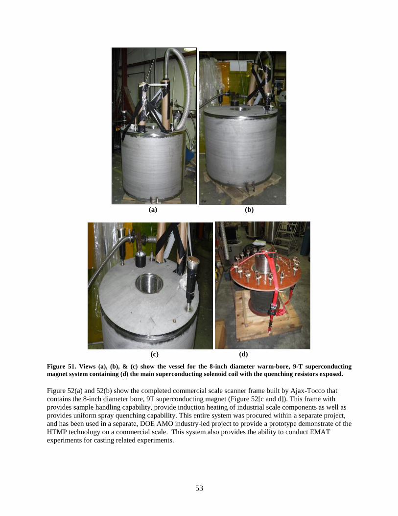
53
(a) (b)
(c) (d)
Figure 51. Views (a), (b), & (c) show the vessel for the 8-inch diameter warm-bore, 9-T superconducting
magnet system containing (d) the main superconducting solenoid coil with the quenching resistors exposed.
Figure 52(a) and 52(b) show the completed commercial scale scanner frame built by Ajax-Tocco that
contains the 8-inch diameter bore, 9T superconducting magnet (Figure 52[c and d]). This frame with
provides sample handling capability, provide induction heating of industrial scale components as well as
provides uniform spray quenching capability. This entire system was procured within a separate project,
and has been used in a separate, DOE AMO industry-led project to provide a prototype demonstrate of the
HTMP technology on a commercial scale. This system also provides the ability to conduct EMAT
experiments for casting related experiments.
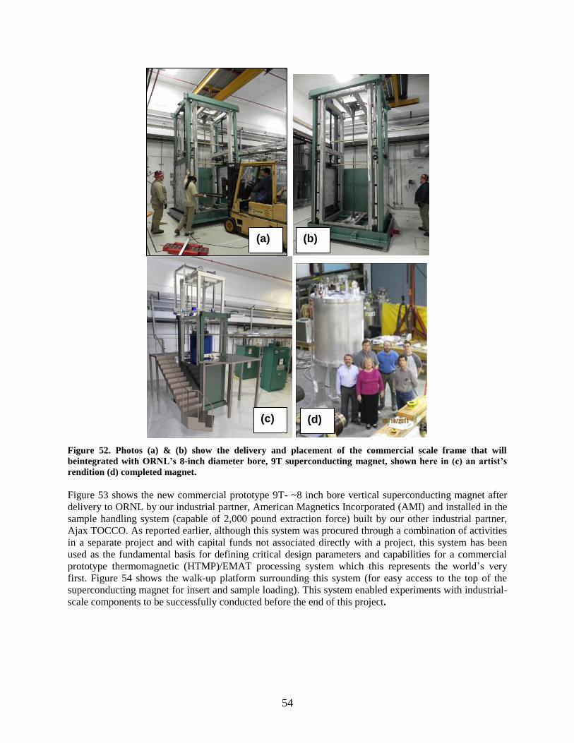
54
Figure 52. Photos (a) & (b) show the delivery and placement of the commercial scale frame that will
beintegrated with ORNL’s 8-inch diameter bore, 9T superconducting magnet, shown here in (c) an artist’s
rendition (d) completed magnet.
Figure 53 shows the new commercial prototype 9T- ~8 inch bore vertical superconducting magnet after
delivery to ORNL by our industrial partner, American Magnetics Incorporated (AMI) and installed in the
sample handling system (capable of 2,000 pound extraction force) built by our other industrial partner,
Ajax TOCCO. As reported earlier, although this system was procured through a combination of activities
in a separate project and with capital funds not associated directly with a project, this system has been
used as the fundamental basis for defining critical design parameters and capabilities for a commercial
prototype thermomagnetic (HTMP)/EMAT processing system which this represents the world’s very
first. Figure 54 shows the walk-up platform surrounding this system (for easy access to the top of the
superconducting magnet for insert and sample loading). This system enabled experiments with industrial-
scale components to be successfully conducted before the end of this project.
(a) (b)
(c) (d)
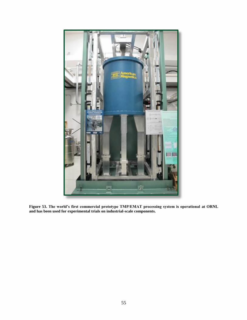
55
Figure 53. The world’s first commercial prototype TMP/EMAT processing system is operational at ORNL
and has been used for experimental trials on industrial-scale components.

56
Figure 54. The ORNL commercial prototype HTMP/EMAT system with working platform installed.
The multiple, world-class HTMP/EMAT facilities established at ORNL are shown in Figure 55 along
with their capabilities.
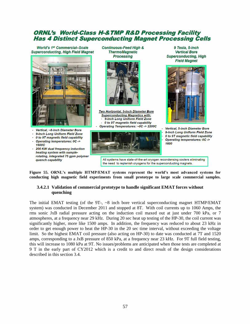
57
Figure 55. ORNL’s multiple HTMP/EMAT systems represent the world’s most advanced systems for
conducting high magnetic field experiments from small prototype to large scale commercial samples.
3.4.2.1 Validation of commercial prototype to handle significant EMAT forces without
quenching
The initial EMAT testing (of the 9T-, ~8 inch bore vertical superconducting magnet HTMP/EMAT
system) was conducted in December 2011 and stopped at 8T. With coil currents up to 1060 Amps, the
rms sonic JxB radial pressure acting on the induction coil maxed out at just under 700 kPa, or 7
atmospheres, at a frequency near 29 kHz. During 20 sec heat up testing of the HP-30, the coil current was
significantly higher, more like 1500 amps. In addition, the frequency was reduced to about 23 kHz in
order to get enough power to heat the HP-30 in the 20 sec time interval, without exceeding the voltage
limit. So the highest EMAT coil pressure (also acting on HP-30) to date was conducted at 7T and 1520
amps, corresponding to a JxB pressure of 850 kPa, at a frequency near 23 kHz. For 9T full field testing,
this will increase to 1080 kPa at 9T. No issues/problems are anticipated when those tests are completed at
9 T in the early part of CY2012 which is a credit to and direct result of the design considerations
described in this section 3.4.

58
59
4. CONCLUSIONS AND RECCOMENDATIONS
The HMFP/EMAT technology has been shown to be an enabling disruptive technology that can
achieve significant improvements in microstructure and performance metrics unachievable through
conventional processing avenues.
Reduction of retained austenite in high carbon/high alloy content steels was demonstrated by
an ambient temperature HTMP process replacing either a cryogenic or double tempering
operations normally employed to accomplish this reduction. HMFP can be described as a
“heat-free, heat treating technology”. Lower residual stresses are anticipated since no thermal
strains are involved in reducing the retained austenite content of the steel.
Simultaneous increases of 12% in yield strength and 22% in impact energy were achieved in
a bainitic alloy using HTMP processing. This is a major breakthrough in materials processing
for the next generation of structural materials since normally strength and toughness change
in opposite directions, and HTMP provides a new paradigm to beneficially increase both of
these properties simultaneously.
HTMP refines both the martensite lathe population and the carbide dispersion in the bainitic
alloy during GausstemperingTM
which is believed responsible for the simultaneous increase in
strength and toughness. Hence, HTMP significantly impacts nucleation and growth
phenomenon.
HTMP develops comparable ultimate tensile strength and twice the impact energy in a lower
cost, lower alloy content (~8% in the bainitic steel) steel compared to the much higher cost,
highly alloyed (31% alloy elements involving Ni, Co, and Mo) 250-grade maraging steel.
Future low-cost HTMP alloys appear viable that will exceed the performance of much more
highly alloyed materials processed conventionally, enabling U.S. industry to reduce cost and
better compete globally while maintaining or exceeding current performance metrics.
EMAT processed cast iron exhibits significantly higher hardness (by 51% for a 9T condition)
than a no-field processed sample.
EMAT microstructures in cast iron are very different in graphite nodule morphology, in
pearlite content, and in the type of carbides that form during the solidification and solid-state
cooling processes.
EMAT processing of nanoparticle dispersions in magnesium results in a very fine,
unagglomerated distribution of the nanoparticles in the matrix material. This provides a
breakthrough technology to make the next generation of nanocomposite reinforced metal
matrix composites which can be tailored to exhibit higher strength and ductility combinations
not only at ambient temperature but also at elevated temperatures with enhanced creep
performance. This technology can be extended to non-metallic systems as long as a
conductive containment vessel is utilized that will convey the EMAT signal into the material
of interest during processing.
Facilitation of HTMP/EMAT technology commercialization occurred throughout the course
of the project. Two technology limitations of the superconducting magnet and induction
heating systems were identified, and new HTMP systems were designed that overcome those
issues leading to the design of the first generation commercial prototype HTMP/EMAT
capable systems which were installed at ORNL. The effort, downtime and expense of regularly replacing liquid cryogens were identified as a
major barrier to commercialization. A recondensing cryocooler system for liquid helium was
designed built and installed on an operating system. A second potential barrier to
commercialization was identified relating to the EMAT effect. When lower frequency was
employed at relatively modest (>2 KW) induction power levels, the EMAT effect cause the
60
superconducting magnet to quench, lose cryogens and no longer be superconducting. Industrial partner AMI implemented several proprietary internal system design changes to
make the superconducting magnet itself very robust against having any EMAT-induced
quenches.
During this project, a production-scale equipment design to enable commercialization of
HMFP technology was conceptualized, designed, fabricated, and installed at ORNL as a
commercial-scale prototype system. The commercial-scale prototype is comprised of a ~8-
inch diameter, warm-bore superconducting magnet and a 220 KW, dual-frequency (10 KHz
and 30 KHz) induction power supply with 75 gpm polymer quenching capability. The system
includes a sample handling system and is capable of an extraction force of 2,000 pounds and
the integrated quench assembly can rotate a component at 30 Hz during the quenching
operation to promote uniform heat transfer boundary conditions. Currently, negotiations are
underway for the technology commercialization licensing of the HTMP/EMAT equipment.
Future R&D projects should pursue these recommendations to expand the applications space for
HTMP/EMAT technologies:
For alloys with large commercial market applications that benefit from retained austenite
conversion by ambient temperature magnetic field processing, evaluate their high cycle
fatigue life for performance enhancement.
Apply the GausstemperTM
process to plain carbon steels for the purpose of refining their
martensite lathe size and inducing a finer and more copious carbide dispersion, with the goal
of simultaneously increasing their yield strength and toughness, extending these low-cost
alloys into higher performance applications normally requiring expensive alloys.
Based on the success of simultaneously increasing the yield strength and toughness for a low
alloy content bainitic steel, examine applying HTMP (GausstemperTM
process) to high-end,
high alloy content steels such as the 350-grade maraging steel (the 350 grade has a ~350 ksi
UTS) to see if yield strength and toughness can be increased significantly above the currently
accepted upper limit values (e.g., move the UTS to 400 ksi).
Expand EMAT studies of cast iron, Al-based, and Mg-based alloys to characterize
improvements in strength and fatigue behavior.
Continue investigations of EMAT processing for making the next generation of high
performance (increases in yield strength, high cycle fatigue, creep, wear resistance, and
conductivity) metal matrix composites for ambient and elevated temperature applications.
Develop predictive models that will provide the required magnetic field energy term(s) for
the Gibbs Free Energy equation to incorporate into predictive phase equilibria and kinetics
codes such as ThermoCalc, Calphad, and Dictra.
Develop appropriate microstructural evolution models (using phase field and/or molecular
dynamics codes) to predict microstructures that develop under HTMP/EMAT conditions.
Conduct in-situ microstructural evolution experiments using advanced neutron diffraction
methods (at ORNL’s Spallation Neutron Source) to validate the analytical tools developed in
the future for predicting new phase equilibria and microstructure morphologies.
Once the current HTMP/EMAT commercialization licensing negotiations are finalized,
announce this agreement and commercial equipment availability in multiple material and
processing trade journals.

61
5. REFERENCES
1. “Magnetic Processing of Structural Components for Transportation Vehicles”, Gail M. Ludtka,
Gerard M. Ludtka, Sean Fleming, and Joaquin del Prado Villasana, Final CRADA Report for
ORNL CRADA No. NFE -09-02418, September 30, 2011.
2. “An Attractive Materials Process: Exploring High Magnetic Field Processing for Developing
Customized Microstructures with Enhanced Performance”, Mackiewicz-Ludtka, et al., 2007,
Symposium Proceedings of the 2007 ASM Heat Treat Society Conference & Exposition,
Detroit, MI, September 17-19-2007.
3. “Time-Resolved Analyses of Microstructure in Advanced Materials under High Magnetic Fields
at Elevated Temperature Using Neutrons”, Ludtka, et al, (invited paper) in Materials
Processing Under the Influence of External Fields, Q. Han, G. Ludtka, and Q. Zhai, editors,
Symposium Proceedings from the TMS 2007 Annual Meeting, Orlando, FL, February 25-
March 1, 2007, TMS Publishers, Warrendale, PA, 2007.
4. “Isothermal Phase Transformation Cycling in Steel by Application of a High Magnetic Field”,
Ludtka, et al, in Materials Processing Under the Influence of External Fields, Q. Han, G.
Ludtka, and Q. Zhai, editors, Symposium Proceedings from the TMS 2007 Annual Meeting,
Orlando, FL, February 25-March 1, 2007, TMS Publishers, Warrendale, PA, 2007.
5. “Retained Austenite in SAE 52100 Steel Post Magnetic Processing and Heat Treatment”, Ludtka,
et al, in Materials Processing Under the Influence of External Fields, Han, Ludtka, and Zhai,
editors, Symposium Proceedings from the TMS 2007 Annual Meeting, Orlando, FL,
February 25-March 1, 2007, TMS Publishers, Warrendale, PA, 2007.
6. “Exploring Ultrahigh Magnetic Field Processing of Materials for Developing Customized
Microstructures and Enhanced Performance”, Ludtka, et al, in Materials Processing in
Magnetic Fields (Eds. Schneider-Muntau, H. J. and Wada, H.), World Scientific Publishing,
New Jersey, pp 55-65 (2005).
7. “Texture Evolution in Fe-1%Si As A Function of High Magnetic Field”, T. A. Bennett, R. A.
Jaramillo, D. E. Laughlin, J. B. Wilgen, R. Kisner, G. Mackiewicz-Ludtka, G. M. Ludtka, P.
N. Kalu, and A. D. Rollett, Solid State Phenomena, (105), 2005, 151-156.
8. "In-situ Evidence of Enhanced Phase Transformation Kinetics Due to a High Magnetic Field in a
Medium Carbon Steel", Ludtka, et al, Scripta Materialia, (51), 2004, 171-174.
9. "The Effect of High Magnetic Field Annealing on Enhanced Phase Stability in 85Fe-15Ni",
Ludtka, et al, Journal of Applied Physics, (95) No. 11, June 2004, 6580-6582.
10. "Effect of 30 Tesla Magnetic Field on Phase Transformations in a Bainitic High-Strength Steel”,
R. A. Jaramillo, S. S. Babu, G. M. Ludtka, R. A. Kisner, J. B. Wilgen, G. Mackiewicz-
Ludtka, D. M. Nicholson, S. M. Kelly, M. Murugananth, and H. K. D. H. Bhadeshia, Scripta
Materialia, (52), 2005, 461-466.
11. “Investigation of Austenite Decomposition in High-Carbon High Strength Fe-C-Si-Mn Steel
under 30 Tesla Magnetic Field”, Jaramillo, R.A., Babu, S., Miller, M.K., Ludtka, G.M.,
Mackiewicz-Ludtka, G. Kisner, R.A., Wilgen, J.B. and Bhadeshia, H.K.D.H, Proceedings of
Int’l Conf. on Solid-Solid Phase Transformations in Inorganic Materials 2005, May 29-June
3, 2005, Phoenix, Arizona.
12. “Investigation of Phase Transformation Kinetics and Microstructural Evolution in 1045 and
52100 Steel under Large Magnetic Fields”, Jaramillo, R.A., Ludtka, G.M., Kisner, R.A.,
Nicholson, D.M., Wilgen, J.B., Mackiewicz-Ludtka, G., Bembridge, N. and Kalu, P.N.,
Proceedings of Int’l Conf. on Solid-Solid Phase Transformations in Inorganic Materials 2005,
May 29-June 3, 2005, Phoenix, Arizona.
13. “Exploring Ultrahigh Magnetic Field Processing of Materials for Developing Customized
Microstructures and Enhanced Performance”, Ludtka, G. M., Jaramillo, R. A., Kisner, R. A.,
62
Mackiewicz-Ludtka, G., Wilgen, J. B., ORNL Tech. memo, ORNL/TM-2005/79, March
2005.
14. “Annual Report”, American Iron and Steel Institute, 2006, Washington, DC,
http://www.steel.org/
15. “Characterization of Retained Austenite and Carbides in Stainless Steel by Combined EBSD,
EDS, and XRD”. Parish, C.; Watkins, T.; Rios, O.; Mackiewicz-Ludtka, G.; Ludtka, G.;
Cavin, O. Publication: Microscopy and Microanalysis, vol. 17, issue S2, pp. 410-411.
16. “Microstructural Modification of a Cast Iron by Magnetic Field Processing”, E.A. Kenik, G.
Mackiewicz-Ludtka , G.M. Ludtka, J.B. Wilgen and R.A. Kisner, Conference Proceedings
Microscopy and Microanalysis 2010, Cambridge University Press.
17. “Electron Microscopy Study of Hypo-Stoichiometric Fe-Pd Nanocomposites Resulting from
Combined Reaction Thermomechanical Processing”, E. D. Cantando, G. M. Ludtka G.
Mackiewicz-Ludtka, and W. A. Soffa, 2011, Solid State Phenomenon, v. 172-174, p.356-361.