Embed Size (px)
Citation preview

Magnetic energy harvesting and concentration at a distance by transformation optics
Article (Published Version)
http://sro.sussex.ac.uk
Navau, Carles, Prat-Camps, Jordi and Sanchez, Alvaro (2012) Magnetic energy harvesting and concentration at a distance by transformation optics. Physical Review Letters, 109 (263903). pp. 1-5. ISSN 0031-9007
This version is available from Sussex Research Online: http://sro.sussex.ac.uk/id/eprint/75337/
This document is made available in accordance with publisher policies and may differ from the published version or from the version of record. If you wish to cite this item you are advised to consult the publisher’s version. Please see the URL above for details on accessing the published version.
Copyright and reuse: Sussex Research Online is a digital repository of the research output of the University.
Copyright and all moral rights to the version of the paper presented here belong to the individual author(s) and/or other copyright owners. To the extent reasonable and practicable, the material made available in SRO has been checked for eligibility before being made available.
Copies of full text items generally can be reproduced, displayed or performed and given to third parties in any format or medium for personal research or study, educational, or not-for-profit purposes without prior permission or charge, provided that the authors, title and full bibliographic details are credited, a hyperlink and/or URL is given for the original metadata page and the content is not changed in any way.

Magnetic Energy Harvesting and Concentration at a Distance by Transformation Optics
Carles Navau, Jordi Prat-Camps, and Alvaro Sanchez*
Grup d’Electromagnetisme, Departament de Fısica, Universitat Autonoma de Barcelona,08193 Bellaterra, Barcelona, Catalonia, Spain
(Received 21 August 2012; published 28 December 2012)
Based on transformation optics, we introduce a magnetic shell with which one can harvest magnetic
energy and distribute it as desired in space with unprecedented efficiency at an arbitrary scale. It allows a
very large concentration of magnetic energy in a free space region, which can be used for increasing the
sensitivity of magnetic sensors, and the transfer of magnetic energy from a source to a given distant point
separated by empty space, with possible applications in wireless transmission of energy.
DOI: 10.1103/PhysRevLett.109.263903 PACS numbers: 41.20.�q, 75.90.+w, 85.25.�j, 85.75.Ss
Transformation optics has pushed the possibilities ofcontrolling light towards unexplored limits [1,2], includingperfect lenses [3] and electromagnetic cloaks [4,5]. Whenapplied to static magnetic [6,7] or electric fields [8,9], trans-formation optics ideas have allowed unique results such asthe experimental realization of an exact cloak [10]. Animportant application of transformation optics is concen-tration of electromagnetic energy, which is attempted usingplasmonics [11,12] or macroscopic concentrators [13]. Theformer only concentrates at subwavelength scales (typi-cally, nanometers for visible or infrared light [14]) and thelatter requires filling the concentration space with material[13,15]. Herewe apply transformation optics ideas to shapeand concentrate magnetic fields in an unprecedented way,by introducing a design that does not require material in itsinterior, so it represents an ideal collector for energy har-vesting or for increasing the sensitivity of a magnetic sen-sor. The same device surrounding a magnetic source willenhance the field in the exterior. The combination of thesetwo features will allow us to transfer magnetic energy froma source to a desired distant point through free space. This isan unusual effect because static magnetic fields naturallydecay with the distance from the source (in the typical caseof a magnetic dipole, as one over the third power of thedistance). We will show that other unique properties can beachieved by combining several specimens of our magneticshell with or without magnetic sources in their interior; forexample, two magnetic sources each surrounded by ourshells get an enhanced magnetic coupling, which mayhave applications in wireless transmission of energy.
Consider an infinitely long (along the z direction) cylin-drical shell of interior and exterior radii R1 and R2, respec-tively, dividing the space in three domains: interior(� < R1), exterior (� > R2), and shell (R1 < �< R2)regions. To fulfill our goals, we will demonstrate that it issufficient that (i) given a source of magnetic energy in theexterior, the shell concentrates all the magnetic energy thatwould be in the material transferring it to the hole, and(ii) if the source is in the interior, the shell energy istransferred to the exterior.
We start by considering the magnetic source in theexterior domain; we want our shell to transfer all the shellenergy into its hole. The required shell material can bedetermined by the transformation optics technique [1,2],linearly compressing the region from � ¼ 0 to � ¼ R2 � �in the interior domain and expanding the annulus from � ¼R2 � � to � ¼ R2 in the shell region through a higher-order polynomial transformation (see SupplementalMaterial, Sec. I [16]) [17]. In the � ! 0 limit no space isleft in the shell region which means that all the energy isconcentrated inside. As the exterior space is not trans-formed, the exterior magnetic field (and energy) distribu-tion is unaffected. This allows us to understand whymagnetic energy is totally transferred from the shell tothe hole: the exterior magnetic energy is unaltered,whereas in the shell volume the energy is zero (from thetransformation it can be seen that within the shell B isradial and H angular so its product B �H, the magneticenergy density, is zero), so it can only go to the hole.The material in the shell has to be homogeneous andanisotropic with radial and angular relative permeabilities�� ! 1 and�� ! 0. Interestingly, even though the interior
space is transformed, nomaterial is needed in the hole (unlikethe electromagnetic waves case [13]). For such a shell in auniform applied field, the field in the hole HHOL is uniform,has the direction of the applied fieldH0, and its magnitudeis increased with respect to H0 by a factor of R2=R1,
HHOL ¼ H0
R2
R1
: (1)
Similar results can be obtained for an actual 3D shape, likea spherical shell. The magnetic behavior of the shell can beseen in Fig. 1(a); a large field concentration is achievedinside while keeping the external field not distorted.One can arrive at Eq. (1) by another path. FromMaxwell
equations, we have analytically solved the general case of ahomogeneous and anisotropic shell in a uniform appliedfield (see Supplemental Material, Sec. III [16]). We noticeespecially two results. First, the condition �� ¼ 1=��
implies no distortion of the external field [7]. Second, for
PRL 109, 263903 (2012) P HY S I CA L R EV I EW LE T T E R Sweek ending
28 DECEMBER 2012
0031-9007=12=109(26)=263903(5) 263903-1 � 2012 American Physical Society

a given R2=R1 ratio, the field in the hole increases whenincreasing �� (for fixed ��) and also when decreasing ��
(for fixed ��). The absolute maximum for magnetic field
concentration is achieved in the limit��!1 and�� ! 0,
so it corresponds to a nondistortion case, and has the valuegiven in Eq. (1).
Concerning the practical realization of our device, ourconcentrator requires �� ! 1 and �� ! 0; actual mate-
rials with such anisotropy do not exist. But an approxima-tion consisting of an alternation of N radially displacedferromagnetic and superconductor wedges (or even rect-angular prisms) constitutes a natural discretization of therequired material as the ferromagnets give the large radialpermeability and the alternated superconductors cancel theangular components of the B field, leading to an effective�� ¼ 0, as demonstrated in Figs. 1(b)–1(d) (all numericalcalculations in this Letter use the magnetostatics module ofCOMSOL MULTIPHYSICS software). For large N—easily
achieved in practice with thin sheets—the field in thehole is very homogeneous and approaches the exact limit.Such superconducting and ferromagnetic materials arecommercially available. In Ref. [10] we fabricated a mag-netic cloak using these two materials, and their idealbehavior was experimentally confirmed for fields as largeas 40 mT and liquid nitrogen temperatures (in the presentcase the permeability of the magnetic layers should be
larger, so permalloy or similar alloys could be used).Regarding an eventual application of our results to lowfrequency magnetic fields, we have experimentally con-firmed that the cloaking effect obtained in Ref. [10] is stillpresent when magnetic field oscillates at frequencies up toaround 100 Hz at least [18].For small applied field values as required for sensitive
magnetic sensors, the behavior of the real materials will bevery close to the ideal case. For large applied fields, super-conductors have been used to concentrate magnetic energywith standard procedures for applied fields up to severalteslas in magnetic lenses [19] but the saturation of theferromagnets may decrease their permeability.Our results could be applied to increasing the sensitivity
of magnetic sensors, like superconducting quantum inter-ference devices, magnetoresistance, or Hall sensors.Magnetic concentration is typically used to enhance theirsensitivity [20–25], by either ferromagnetic materials,attracting magnetic flux, or diamagnetic ones, repellingit—superconductors being the optimum diamagnetic ma-terials. The usual concentration strategy is based on twosuperconductors—or two ferromagnets—separated by agap at which flux concentration is produced. We show inFigs. 2(a) and 2(b) a typical example of concentration of a
FIG. 1 (color online). Magnetic field lines and their density(in color; in units of applied magnetic field) for (a) the idealcylindrical magnetic concentrator shell with homogenous aniso-tropic permeabilities �� ! 1 and �� ! 0 and radii ratio
R2=R1 ¼ 4, and three discretized versions: (b) 36 wedges ofalternating homogenous and isotropic ideal superconducting(� ¼ 0:0001) and ideal soft ferromagnetic (� ¼ 10 000)wedges; (c) same with 72 wedges; and (d) same with 72rectangular prisms, for which a very good behavior is obtainedeven though materials do not fill the whole shell volume.
FIG. 2 (color online). Common strategies for field concentra-tion use the gap between two superconductors. In (a) and (b)we show the magnetic energy density (normalized to thatof applied field) for two ideal superconducting blocks (� ¼0:0001) with a thickness w separated by a gap b and decreasingheights h ¼ (a) 4b, and (b) b=10, in a vertical applied magneticfield. In (c), our optimum homogeneous anisotropic concentrat-ing shell (�� ! 1 and �� ! 0) with R2=R1 ¼ 4 shows a large
uniform energy density in its hole (for the comparison, noticethat 2R1 ¼ b and w ¼ R2 � R1). In (d), a homogeneous iso-tropic shell made of ideal soft ferromagnetic material with thesame dimensions as (c) attracts more field lines from outside butcannot bring them to the hole, so the inner energy density is zero.
PRL 109, 263903 (2012) P HY S I CA L R EV I EW LE T T E R Sweek ending
28 DECEMBER 2012
263903-2

uniform applied magnetic field in the gap of two super-conducting slabs (assumed ideal, with zero relative perme-ability � [10]). The field gets enhanced at the edges of theslabs, not only on the gap region but also on the exteriorones. When reducing the slabs’ thicknesses, the contribu-tion from the edges adds up and a rather intense magneticfield develops in the gap [Fig. 2(b)], although the gap fieldis not homogeneous but increases towards the strip edgesand decreases at the central region. For our shell withpermeabilities �� ! 1 and �� ! 0, an applied magnetic
field will be enhanced homogeneously in the shell hole bya factor R2=R1 [Eq. (1)], so a magnetic sensor placed therewould detect a much larger flux—increasing its sensitivityby a large known factor—at the price of an increase of theoverall footprint of the sensor [24,26]. By comparing withthe superconductors case, in our design not only is theaverage field in the hole always larger [Fig. 2(c)], butalso the magnetic flux is always constant, whereas for thegap strategy the flux tends to zero (Supplemental Material,Fig. S7 [16]) [27] because field lines are mainly divertedtoward the exterior edges when the gap is narrowed. Ourconcentration design is optimum because all the magneticenergy enclosed in the material region is totally transferredto the hole. Another case of interest is for sensing nonuni-form fields from nearby magnetic sources, as in biosensors[28], in measuring human brain response in magnetoence-phalography [29,30] or for detecting single magneticmicrobeads [31]. Often in these situations the gradient ismeasured rather than the field, in order to separate thesignal of the source from other distant noise sources.Transformation optics allows us to analytically obtain themagnetic field and its gradient at any point of the hole(Supplemental Material, Sec. IB [16]). The gradientbecomes scaled by a higher power of the radii relation[ðR2=R1Þ2 for the gradient of a dipolar source], whichmakes our concentrator particularly useful for magneticgradiometers.
We now study the case when the magnetic source isplaced inside; we want all the magnetic energy in the shellto be expelled towards the exterior domain. The requiredmaterial is designed by transforming the space so that theshell space is totally pushed out. Interestingly, applyinganalogous linear and higher-order polynomial transforma-tions we find that the required shell is exactly thesame homogeneous anisotropic shell with �� ! 1 and
�� ! 0 that we designed for energy concentration above(Supplemental Information, Sec. II [16]).
The shell property of transferring all the magnetic en-ergy in the shell to the exterior when there is a source in thehole is illustrated in Figs. 3(a)–3(c). The magnetic energyof a magnetic dipole (e.g., a small magnet) in free space[Fig. 3(a)] is expelled outward by enclosing the dipole withour shell [Fig. 3(b)]. Interestingly, outside the shell the fieldis exactly the same as it would be if there were a centereddipole in empty space, with a magnetic moment enhanced
by a factor R2=R1. In particular, this enhanced magneticmoment can ideally be made arbitrarily large by making R1
arbitrarily small. Intuitively, this can be understood if wetake into account that the shell expels the magnetic energythat would be in the shell volume towards the exterior, anda small R1 implies that the shell extends to points near thedipole, where the energy density arbitrarily increases.When adding a second shell at a given far distance, theenhanced field of the first dipole is harvested by the secondshell and concentrated in its hole [Fig. 3(c)]: magneticenergy has been transferred from the dipole to a desiredposition through empty space. Analytical expressions forthe field in all these cases are obtained by the correspond-ing space transformations (Supplemental Material,Eqs. S32 and S15 [16]), and also for any other configura-tion different from the vertical centered dipole (throughthe general transformations in Eqs. S8 and S26 [16]).This transfer of magnetic energy through free space isachieved in spite of the general property—also fulfilledin the region between the two concentrators in our case—that any static magnetic field naturally decays with dis-tance in free space [32].
FIG. 3 (color online). Left panels: the magnetic energy densityof a cylindrical dipole (e.g., a small magnet) (a) is spatiallyredistributed towards larger radial distances by the use of ourshell with R2=R1 ¼ 8 (b); in (c) a second concentrator harveststhe enhanced magnetic energy in its volume and transfers it to itshole, where a large value of magnetic energy is achieved. Rightpanels: in (d) magnetic energy density of two identical cylindri-cal dipoles separated a given gap; when separating and enclosingthem with two of our shells with R2=R1 ¼ 4 [(e)] the magneticenergy density in the middle free space is similar to that in (d);when the inner radii of the shells are reduced to R2=R1 ¼ 10[(f)] the magnetic energy is concentrated in the free spacebetween the enclosed dipoles, enhancing the magnetic coupling.
PRL 109, 263903 (2012) P HY S I CA L R EV I EW LE T T E R Sweek ending
28 DECEMBER 2012
263903-3
Many combinations of shells with or without innersources may be constructed based on these ideas. As anexample with possible interest for applications, we show inFigs. 3(d)–3(f) how the magnetic coupling between twodipoles separated by a given free-space gap can be sub-stantially enhanced by separating and surrounding themwith two of our shells. This enhanced magnetic couplingmay have relevance to wireless power transmission [33],where a key factor for achieving this goal is to increase themutual inductive coupling between the source and thereceiver resonators [34]. Although our ideas strictly applyto static fields, extension to other frequency ranges such asthose used in power wireless transmission would be pos-sible if materials with the required permeability values atsuch nonzero frequencies are available, possibly usingmetamaterials [35].
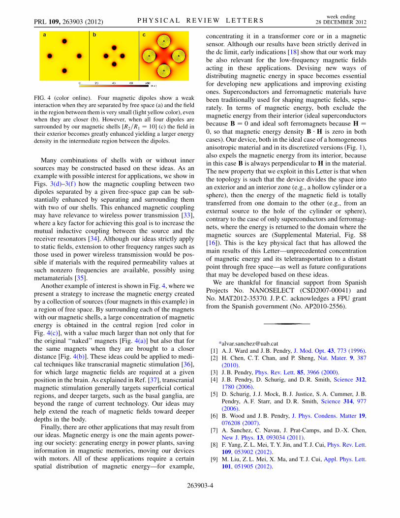
Another example of interest is shown in Fig. 4, where wepresent a strategy to increase the magnetic energy createdby a collection of sources (four magnets in this example) ina region of free space. By surrounding each of the magnetswith our magnetic shells, a large concentration of magneticenergy is obtained in the central region [red color inFig. 4(c)], with a value much larger than not only that forthe original ‘‘naked’’ magnets [Fig. 4(a)] but also that forthe same magnets when they are brought to a closerdistance [Fig. 4(b)]. These ideas could be applied to medi-cal techniques like transcranial magnetic stimulation [36],for which large magnetic fields are required at a givenposition in the brain. As explained in Ref. [37], transcranialmagnetic stimulation generally targets superficial corticalregions, and deeper targets, such as the basal ganglia, arebeyond the range of current technology. Our ideas mayhelp extend the reach of magnetic fields toward deeperdepths in the body.
Finally, there are other applications that may result fromour ideas. Magnetic energy is one the main agents power-ing our society: generating energy in power plants, savinginformation in magnetic memories, moving our deviceswith motors. All of these applications require a certainspatial distribution of magnetic energy—for example,
concentrating it in a transformer core or in a magneticsensor. Although our results have been strictly derived inthe dc limit, early indications [18] show that our work maybe also relevant for the low-frequency magnetic fieldsacting in these applications. Devising new ways ofdistributing magnetic energy in space becomes essentialfor developing new applications and improving existingones. Superconductors and ferromagnetic materials havebeen traditionally used for shaping magnetic fields, sepa-rately. In terms of magnetic energy, both exclude themagnetic energy from their interior (ideal superconductorsbecause B ¼ 0 and ideal soft ferromagnets because H ¼0, so that magnetic energy density B �H is zero in bothcases). Our device, both in the ideal case of a homogeneousanisotropic material and in its discretized versions (Fig. 1),also expels the magnetic energy from its interior, becausein this case B is always perpendicular toH in the material.The new property that we exploit in this Letter is that whenthe topology is such that the device divides the space intoan exterior and an interior zone (e.g., a hollow cylinder or asphere), then the energy of the magnetic field is totallytransferred from one domain to the other (e.g., from anexternal source to the hole of the cylinder or sphere),contrary to the case of only superconductors and ferromag-nets, where the energy is returned to the domain where themagnetic sources are (Supplemental Material, Fig. S8[16]). This is the key physical fact that has allowed themain results of this Letter—unprecedented concentrationof magnetic energy and its teletransportation to a distantpoint through free space—as well as future configurationsthat may be developed based on these ideas.We are thankful for financial support from Spanish
Projects No. NANOSELECT (CSD2007-00041) andNo. MAT2012-35370. J. P. C. acknowledges a FPU grantfrom the Spanish government (No. AP2010-2556).
*[email protected][1] A. J. Ward and J. B. Pendry, J. Mod. Opt. 43, 773 (1996).[2] H. Chen, C. T. Chan, and P. Sheng, Nat. Mater. 9, 387
(2010).[3] J. B. Pendry, Phys. Rev. Lett. 85, 3966 (2000).[4] J. B. Pendry, D. Schurig, and D. R. Smith, Science 312,
1780 (2006).[5] D. Schurig, J. J. Mock, B. J. Justice, S. A. Cummer, J. B.
Pendry, A. F. Starr, and D. R. Smith, Science 314, 977(2006).
[6] B. Wood and J. B. Pendry, J. Phys. Condens. Matter 19,076208 (2007).
[7] A. Sanchez, C. Navau, J. Prat-Camps, and D.-X. Chen,
New J. Phys. 13, 093034 (2011).[8] F. Yang, Z. L. Mei, T. Y. Jin, and T. J. Cui, Phys. Rev. Lett.
109, 053902 (2012).[9] M. Liu, Z. L. Mei, X. Ma, and T. J. Cui, Appl. Phys. Lett.
101, 051905 (2012).
FIG. 4 (color online). Four magnetic dipoles show a weakinteraction when they are separated by free space (a) and the fieldin the region between them is very small (light yellow color), evenwhen they are closer (b). However, when all four dipoles aresurrounded by our magnetic shells [R2=R1 ¼ 10] (c) the field intheir exterior becomes greatly enhanced yielding a larger energydensity in the intermediate region between the dipoles.
PRL 109, 263903 (2012) P HY S I CA L R EV I EW LE T T E R Sweek ending
28 DECEMBER 2012
263903-4

[10] F. Gomory, M. Solovyov, J. Souc, C. Navau, J. Prat-Camps, and A. Sanchez, Science 335, 1466 (2012).
[11] J. A. Schuller, E. S. Barnard, W. Cai, Y. C. Jun, J. S. White,and M. L. Brongersma, Nat. Mater. 9, 193 (2010).
[12] A. Aubry, D.Y. Lei, A. I. Fernandez-Domınguez, Y.Sonnefraud, S. A. Maier, and J. B. Pendry, Nano Lett.10, 2574 (2010).
[13] M. Rahm, D. Schurig, D.A. Roberts, S. A. Cummer, D. R.Smith, and J. B. Pendry, Photon. Nanostr. Fundam. Appl.6, 87 (2008).
[14] D. K. Gramotnev and S. I. Bozhevolnyi, Nat. Photonics 4,83 (2010).
[15] A possible exception of this would be the particular caseof a TEM wave propagating along the translational sym-metry axis z. In this unique situation both electric andmagnetic fields would be in the xy plane (having no zcomponent) so that we could simultaneously ignore theequal nonzero values of permittivity "zz and permeability�zz required in the interior part of the concentrator. In thisvery special situation no material would be needed insidethe concentrator even for electromagnetic waves.
[16] See Supplemental Material at http://link.aps.org/supplemental/10.1103/PhysRevLett.109.263903 for addi-tional theoretical developments.
[17] S. A. Cummer, R. Liu, and T. J. Cui, J. Appl. Phys. 105,056102 (2009).
[18] J. Souc, F. Gomory, M. Solovyov, C. Navau, J. Prat-Camps, and A. Sanchez (unpublished).
[19] S. Choi, J.-H. Yoon, B.-S. Lee, M.-S. Won, J.-W. Ok, Z. Y.Zhang, T. Kiyoshi, S. Matsumoto, and S.-H. Lee, J. Appl.Phys. 111, 07E728 (2012).
[20] D. Robbes, Sens. Actuators A 129, 86 (2006).[21] M. Pannetier, C. Fermon, G. Le Goff, J. Simola, and E.
Kerr, Science 304, 1648 (2004).
[22] P. Ripka and M. Janosek, IEEE Sens. J. 10, 1108 (2010).[23] J. Lenz and A. S. Edelstein, IEEE Sens. J. 6, 631 (2006).[24] W.C. Griffith, R. Jimenez-Martinez, V. Shah, S. Knappe,
and J. Kitching, Appl. Phys. Lett. 94, 023502 (2009).[25] R. Kleiner, D. Koelle, L. Ludwig, and J. Clarke, Proc.
IEEE 92, 1534 (2004).[26] A. Alu and N. Engheta, Phys. Rev. Lett. 102, 233901
(2009).[27] A. A. B. Brojeny, Y. Mawatari, M. Benkraouda, and J. R.
Clem, Supercond. Sci. Technol. 15, 1454 (2002).[28] S. X. Wang and G. Li, IEEE Trans. Magn. 44, 1687 (2008).[29] V. Pizzella, S. Della Penna, C. Del Gratta, and G. L.
Romani, Supercond. Sci. Technol. 14, R79 (2001).[30] R. L. Fagaly, Rev. Sci. Instrum. 77, 101101 (2006).[31] P.-A. Besse, G. Boero, M. Demierre, V. Pott, and R.
Popovic, Appl. Phys. Lett. 80, 4199 (2002).[32] Throughout this Letter, we have used the concept ‘‘trans-
fer of magnetic energy.’’ In the strict dc case this conceptmay be not well defined, but when considering the dc caseas actually the limit of very low-frequency ac fields thetransfer has now full meaning since energy could be put inat the source end and extracted at the sink end to do usefulwork.
[33] A. Kurs, A. Karalis, R. Moffatt, J. D. Joannopoulos, P.Fisher, and M. Soljacic, Science 317, 83 (2007).
[34] D. Huang, Y. Urzhumov, D. R. Smith, K.H. Teo, andJ. Zhang, J. Appl. Phys. 111, 064902 (2012).
[35] M. C.K. Wiltshire, J. B. Pendry, I. R. Young, D. J.Larkman, D. J. Gilderdale, and J. V. Hajnal, Science 291,849 (2001).
[36] M. Kobayashi and A. Pascual-Leone, Lancet Neurology 2,145 (2003).
[37] G. Bonmassar, S.W. Lee, D.K. Freeman, M. Polasek, S. I.Fried, and J. T. Gale, Nat. Commun. 3, 921 (2012).
PRL 109, 263903 (2012) P HY S I CA L R EV I EW LE T T E R Sweek ending
28 DECEMBER 2012
263903-5