Embed Size (px)
Citation preview

JOURNAL OF GEOPHYSICAL RESEARCH, VOL. 102, NO. B10, PAGES 22,681-22,694, OCTOBER 10, 1997
Magnetic domains and domain walls in pseudo-single-domain magnetite studied with magnetic force microscopy
Taras G. Pokhil and Bruce M. Moskowitz
Department of Geology and Geophysics and Institute for Rock Magnetism, University of Minnesota, Minneapolis
Abstract. Magnetic domain and domain wall structures in pseudo-single-domain grains (5-20 gm) of magnetite (Fe304) were studied using magnetic force microscopy. Many of the observed micromagnetic features can be explained by the magnetostatic effects of surfaces and grain edges and interactions within and between walls. Domain walls were frequently subdivided into 1-3 opposite polarity segments separated by Bloch lines, although some walls contained no Bloch lines. Subdivided walls display a characteristic zigzag structure along the easy axis direction, where zigzag angles can be as high as 200-40 ø . The zigzagging structure, in addition to wall segmentation, further minimizes the magnetostatic energy of the walls. Bloch lines can be (de)nucleated during wall displacement or after repeated alternating field (AF) demagnetization. Within individual walls, the number of Bloch lines and their pinning locations were found to vary after repeated AF demagnetization demonstrating that walls, like individual grains, can exist in several different local energy minima. The number of Bloch lines appears to be independent of domain state, but frequently the polarity of the wall was coupled with the direction of magnetization in the adjoining domains, such that wall polarity alternates in sign between adjacent walls across an entire grain. Even after the domain magnetization is reversed, the same sense of wall chirality is maintained across the grain producing unique grain chiralities. For one particular grain it was possible to reconfigure a likely three-dimensional (3-D) domain structure. The body and surface structures result primarily from a combined volume magnetostatic interaction between all grain surfaces and magnetocrystalline anisotropy. Finally, commonly observed open-flux features within the interior of grains or along grain edges terminating planar domains are inconsistent with the prediction of edge closure domain formation based on recent 2- D micromagnetic models. Our observations suggest that 3-D micromagnetic models are required to model results even for grains larger than 1 gm.
1. Introduction
The physics of pseudo-single-domain (PSD) behavior plays a central role in paleomagnetism because most ferrimagnetic oxide grains in rocks are too large to be in an equilibrium single domain (SD) state (>0.1 •tm). Although such grains contain magnetic domains, they can still carry stable natural remanent magnetization. Except for the smallest sized particles below about 0.1 gm, which may be in nearly uniformly magnetized SD states, natural remanent magnetization is carded by nonuniformly magnetized, PSD or small multidomain (MD) particles containing magnetic structures such as internal body domains, surface closure domains, domain walls, spin vortices, or existing in metastable SD-like states [e.g., Dunlop, 1990; Merrill and Halgedahl, 1995]. These micromagnetic structures affect both the origin of natural remanent magnetization, such as thermoremanent magnetization and the fidelity of the paleo- magnetic record against thermoviscous or magnetochemical remagnetization.
Direct imaging of micromagnetic features in PSD and MD grains is one way to study the links between micromagnetic structures of individual grains and macroscopic magnetic properties of rocks like remanence, coercivity, and blocking temperature. In addition, micromagnetic observations can
Copyright 1997 by the American Geophysical Union.
Paper number 97JB01856. 0148-0227/97/97JB-01856509.00
provide key experimental information for validating two- dimensional (2-D) and three-dimensional (3-D) numerical models proposed for remanence states, hysteresis, and thermomagnetic behavior in magnetite [e.g., Xu et aL, 1994; Thompson et aL, 1994; Williams and Dunlop, 1995; Fabian et al., 1996]. The most widely used method for domain structure studies in small grains of natural magnetic materials has been the Bitter method [sorrel, 1971; Halgedahl, 1987, 1995; Ozdemir et al., 1995; Geiss et al., 1996]. Results from Bitter studies have lead to new models for PSD behavior incorporating local energy minima (LEM) remanence states and transdomain remanent magnetization [Halgedahl and Fuller, 1983; Moon and Merrill, 1985; Halgedahl, 1991; McClelland and Shcherbakov, 1995; Ye and Merrill, 1991]. However, the standard Bitter method is an optical technique with a spatial resolution of about 0.5 gm, making it difficult or even impossible to obtain data on the fine structure of the magnetization distribution within domains and domain walls. Furthermore, Bitter patterns may not even effectively image some of the predicted micromagnetic structures [Williams et a/.,1992b; Newell et al., 1993]. Magneto-optic Kerr effect microscopy has also been used to study domain structures in magnetite and other magnetic minerals [Hoffmann et al., 1987, 1990; Worm et al., 1991; Heider and Hoffmann, 1992; Ambatiello and Soffel, 1996]. Despite the advantage over the Bitter method of being able to measure directly the vector components of the surface magnetization in domains, applications of MOKE in rock magnetism rely on optical
22,681
22,682 POKHIL AND MOSKOWITZ: DOMA1NS IN PSEUDO-SINGLE-DOMAIN MAGNETITE
wavelengths, making its spatial resolution similar to the Bitter technique.
A relatively new method for experimental study of magnetic microstructure with high spatial resolution approaching 20-50 nm is magnetic force microscopy (MFM) [Martin and Wickramasinghe, 1987]. With the lateral resolution available with the MFM, this method is capable of providing information on the internal structure of domain walls and the spin distributions within domains as well as the general features of domain structures. The MFM has been used in several
preliminary studies to investigate wall structures in single- crystal magnetite [Williams et al., 1992a; Proksch et al., 1994; Foss et al., 1996]. In this paper we present results of an MFM study of domain and domain wall structures in PSD-sized grains (4-20 gin) of magnetite containing a few domains. We analyze factors that influence the reinanent domain and domain wall
structures and show that many of these micromagnetic features result from magnetostatic effects of surfaces and grain edges, as well as interactions within and between walls.
2. Experimental Methods
Small multidomain (MD) grains (5-50 gm) of magnetite (Fe304) , randomly oriented and dispersed in a nonmagnetic silicate matrix, were produced by the glass-ceramic method [Worm and Market, 1987]. The sample was mounted in epoxy and mechanically polished with diamond compounds. Amorphous silica solution was used as a final polish to obtain a smooth surface and to reduce the strained surface layer produced during the initial mechanical polishing [Hq.ffmann et al., 1987]. The bulk coercive force of the sample was 1.5 mT, the saturation remanence ratio M,/M,=0.011, and the coercivity ratio //,///,=6.3, confirming that most of the grains in our sample are in the MD state.
Instrumentation for magnetic force microscopy is now well developed, but issues related to image formation, interpretation, and limitations of the method are still problematical [e.g., Griitter and Allenspach, 1994]. Image contrast in the MFM is produced by the magnetostatic interaction between magnetic stray fields of the sample and cantilever with a ferromagnetic tip near the sample surface. In the AC mode of operation, which detects the shift of the resonant frequency of oscillating cantilever, the MFM response is proportional to the product of the tip magnetization (m,,•,) and the second spatial derivatives of the stray field B from the sample. If the tip is magnetized along z direction, which is defined as normal to the sample surface and parallel to the oscillation direction, the MFM response is proportional to c•B,/c3z:. It is important to note that the MFM does not provide information directly on the near surface distribution of magnetization. Instead, it is a measure of the local stray field components of micromagnetic structures resulting from distributions of magnetic poles where the magnetization diverges or has a component normal to the surface. This means that quantitative interpretation of MFM data in terms of the magnetization distribution of micromagnetic features is difficult due to the inherent nonuniqueness of the magnetic inverse problem, the requirement for an accurate model of the geometric and magnetic properties of the MFM tip, and the invasive nature of scanning a magnetic tip near a magnetic sample. Despite these fundamental and practical limitations, significant results can still be achieved on length scales appropriate for investigating micromagnetic structures after careful considerations concerning tip magnetization, tip-
sample separation, and scanning orientation. Our procedures follow closely those described by Proksch et al. [1994] and Foss et al. [1996].
Magnetic force gradient images were obtained with a Nanoscope III Multimode TM scanning probe microscope. The microscope was operated in the "tapping/lift" scanning mode, which combines constant interaction and constant height modes, to separate short-range topographic effects from long-range magnetic signals. The scanning probes were batch fabricated Si cantilevers with pyramidal tips coated with a magnetic CoCr film alloy. All MFM data shown in this paper were collected with the tip magnetized nearly perpendicular to the sample surface (i.e., z direction), making the MFM sensitive to the second derivative of the z component of the sample stray field. To exclude any influence of the MFM tip on the sample micromagnetic structure and to verify that any non-z components of the tip magnetization contributed negligibly to the MFM measurements, images were taken with various tip- sample orientations and tip-sample separations (for details, see Foss et al. [1996]). Under these experimental conditions we did not observe significant qualitative modifications of micromagnetic features or profile measurements during MFM scanning of the grains described in this work. All MFM images presented in this paper were obtained by detecting the amplitude of cantilever oscillation with a tip-sample separation of 50 nm. Tip oscillation amplitude was 20-30 nm, and the drive frequency of the cantilever was chosen to be above the resonance frequency of the cantilever near the point of maximum slope of the cantilever resonance curve.
3. Domain Structures in PSD Grains
We investigated domain structures in PSD grains in the 5 to 20 •tm size range containing just a few domains (<10). The domain structures within this size range observed with the MFM can be divided into the following three types depending on the orientation of the domain magnetization relative to the surface of the grain: (1) domain structures with the main component of magnetization parallel to the grain surface (Figure 1), (2) domain structures with the main component of magnetization normal to the grain surface (Figure 2), and (3) domain structures with the main component of magnetization obliquely oriented with the grain surface (Figure 3). Although the actual directions of magnetization cannot be unambiguously determined by the MFM, image contrast due to magnetic charge density variations on the surface of walls and domains can be interpreted in terms of magnetization with a main component oriented nearly parallel, normal, or oblique with respect to the surface of the grain.
3.1. Domain Magnetization Parallel to Grain Surface
When the domain magnetization is approximately parallel to the grain surface, the MFM tip responds more to the stray fields above the domain walls than above the domain interors because
the wall magnetization is normal to the surface. In the grain shown in Figure 1, all domains in the MFM image have nearly the same gray scale levels, but the domain walls are either brighter or darker depending on the sign of interaction between the MFM tip and stray fields from the walls. While the walls are mainly parallel to each other, they are not straight. Walls curve near grain edges (top left and bottom center in Figure l a), near the two surface pores (black spherical features in Figure l a), and within the grain interior. The intersection of the spherical

POKHIL AND MOSKOWITZ: DOMAINS IN PSEUDO-SINGLE-DOMAIN MAGNETITE 22,683
(b)
Figure 1. (a) A 13x13 pm MFM image of a magnetite grain with the direction of the domain magnetization approximately parallel to the surface of the grain. White (black) contrast corresponds to attractive (repulsive) interactions between the MFM tip and the sample stray field. In our experimental setup, attractive (repulsive) response occurs when the tip magnetization is parallel (antiparallel) with the normal component of the sample magnetization. Note that adjacent domain walls alternate in polarity across the grain. (b) Schematic diagram explaining the MFM image in Figure l a. Black areas, DW magnetized down; white areas, DW magnetized up; alternating black and white areas, Bloch lines; plus and minus signs, magnetic charges at the edges of the grain and around inclusions.
pores by the walls helps to reduce the magnetostatic energy associated with the void (Figure lb). Wall bending may be caused by a nonuniform distribution of microstresses [Xu and Merrill, 1992].
The formation of edge closure domains predicted by 2-D micromagnetic models [Xu et al., 1994] would seem to be most favorable for the conditions seen in Figure 1 where the magnetization is nearly in plane and intersects fairly straight grain edges. However, an alternating pattern of white and black contrast along the left and right edges of the grain (Figure 1) indicates that the domain magnetization intersects the edges at a high angle producing poles along these surfaces. In contrast to model predictions, the walls extended to the edges of the grain
without forming edge closure domains. This was a typical observation for PSD grains in the 5-20 •tm size range.
3.2. Interior Domain Structure Determined From Surface
Domain Configuration
It is usually difficult to reconstruct the body domain structure simply from domain patterns on a randomly oriented grain surface because the shape of the grain, crystallographic orientation of the surface and edges, and the direction of the domain magnetization are not always completely known. Fortunately, the grain shown in Figures 1 and 4 has a symmetric rhombic shape, which allows us to estimate the crystallographic orientation of its surface and the directions of the [111] easy axes relative to the surface. An analysis of the domain structure in this particular grain provides an opportunity to assess the relative importance of magnetocrystalline, magnetoelastic, and magnetostatic contributions to micromagnetic structures.
Figure 2. MFM images (15x15 •tm) (a) and (b) of two magnetite grains with domain magnetization oriented approximately normal to the surface of the grain. (c) Schematic diagram showing the domain structure that could produce the MFM images in Figures 2a and 2b.

22,684 POKHIL AND MOSKOWITZ: DOMAINS IN PSEUDO-SINGLE-DOMAIN MAGNETITE
.................. .:7:: ........ ::,,•,':.i:i:¾:'"•:•57" . ,•,::•::..•:., • •!i•,.i::'•.:i• :.'. •:!;5•ii".-.,.g. •-:"':•--'•i!• :.'::":":!!•i..'i• •::::'" .•.:•i5':: '•'::•.i•Y'?:•i•;•5•!:.
..
.:.
.:.
.:.
(b)
Figure 3. (a) (left) MFM image of a magnetite grain and (fight) schematic diagram of the magnetic image. In this case the direction of the domain magnetization is oblique to the surface of the grain, and the component of magnetization normal to the surface is insufficient for formation of maze-like domains. Note the edge closure domains on the top edge of the grain. (b) MFM image of another grain where the direction of the domain magnetization is oblique to the surface of the grain.
Initially after polishing of the sample, domain walls in the grain were mainly parallel to the long diagonal of the rhombic shaped grain (Figure 1). However, after AF demagnetization, walls near the center of the grain changed their orientation in a step-like manner producing wall segments parallel to the short diagonal of the rhomb (Figure 4b). This domain state persisted after further magnetic and thermal treatments of the sample including AF demagnetization, remanence after magnetization in high field, and low-temperature demagnetization, and the original "straight-wall" state was never recovered. This suggests that the "step-like wall" state is the energetically favorable domain state in this particular grain. However, because domain walls ordinarily bisect the directions of magnetization in adjacent domains to minimize magnetic charges on the wall surfaces, it is difficult to explain this feature if the domain magnetization is constrained to be exactly parallel to the surface of the grain unless the step walls represent transitions between "head-on" domains or the domain magnetization is so nonuniform that it can rotate abruptly by 90 ø around the steps. Both possibilities seem unlikely because "head-to-head" domain walls are highly charged, thus unfavorable, and the magnetization direction within the domains should be uniform (otherwise two domains and a new domain wall will form instead of one domain). A better explanation for the domain and domain wall features in this grain follows by considering the crystallographic orientation of the surface.
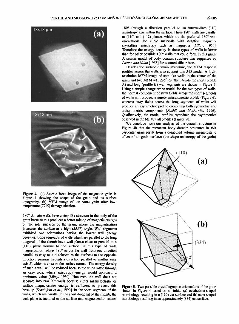
The surface topography of the grain in Figure 4b is shown in Figure 4a. The grain surface has a symmetric shape of a truncated rhomb with interior angles of 68 ø and 112 ø. Assuming that the surfaces of the magnetite grains after sectioning and polishing are random cross sections of grains, the shape of the surface in Figure 4a suggests that the grain initially had either a truncated octahedral shape (Figure 5a) or a cubic shape (Figure 5b). If it was originally a truncated octahedron, then from its included angles the surface should be very close to a (110) plane containing two sets of [ 111 ] easy axes with 71 ø, 109 ø, and 180 ø domain walls. However, the observed domain structure was not consistent with this classical configuration of domains.
Instead, we base our explanation of the observed domain structure on the assumption that the grain surface is a cross section of a cubic shaped grain (Figure 5b) close to the (334) plane. One can show that with this original shape and the observed rhombic cross section, one particular [ 111] easy axis direction is approximately parallel to the long diagonal of the romb (this face is shown in gray in Figure 5b) but inclined about 12 ø with the surface. On all other orthogonal grain faces, the other [ 111] easy axes intersect the surfaces with the same 35.5 ø angle. The magnetization in the grain is apparently aligned along the [111] easy axis that makes the smallest angle with the grain surface (Figure 6).
The inferred body domain structure (Figure 6) consists of two sets of walls either inclined or normal to the surface. The
POKHIL AND MOSKOWITZ: DOMAINS IN PSEUDO-SINGLE-DOMAIN MAGNETITE 22,685
18x18 gm (a)
ß
...... ..i•.:..5•i•:i::.:•i•i•:i.;.•r:.:gi.:..i.:ii.:.:...:.:iii.:•......:..i::...i:i•:? ...... •:--'-'.--.:ii•iii'.-'iiiii}ii:.:i .....
...... • i: 'ß' ;iiiiiiiiiii:::
...... •: .,.•.'!i.;.':
'" . ............ ,e,---'.•-.-...'....-•,•,;':'::";"•? !" ::•:i!.'"'::: ß ..'...---:i:}5ii•::.."i/"::":--' '•-'-':.i..,•i..:-i•:•:;;:i:.:">•i.":'::•-":>:.:;ii :" ":'si:.•...ii:: :.-.. ß -:-:.-.-.-...::..:"•':'"-"':'•:.....:i-.•:,:;-::-•a-.• .... ß ......... : ß ß i:i::::;-:•i:i:ia:i-"•-•*'-"."i•.:.-'Z:i:.-':i:i:i:i:E-5:ii:i.'.4:•.-i::'-i• .:'.:,•i::.........E:i . "",": ...... .
"- :-:.'..'.':.•(.(4%:..!:i:3'.." "----""-"- ---',, ;.....`•.i•:::•.•i•ii...;i...i•.:..•...i{...i•i..?:•i:•i•:•::•:•k...:...``.:}*•s•:i...::•i...a:i•?.:.•:•%..•.:•..• ::..-..•):i.•i.•+'.•."::.;.'•:!:: .... ?i::.':i.:.. ":'
'•i• .::::•:.:::.:;•.:5....`..i•i•:;::?;::.:....:.......z:.;.y.:.:•::•:::...:.•:;.i:;..`.:...%•%.•?•...:;;:•:::!::...?...?•&:.:.•:.:..:..•;•i• ,'.*½:,•?":':"'* ....%•;--"
........ %;•%.•< ........ :'""•"'-'-, ':•. -..'.'•:. •.........E>:::?:::.:'"'"•.-': ........ •:•.•:::..... !.:::•. ............ ..: ................... :.. :.:-:.
... ::.:..:?½g ................... .:..• .... ..
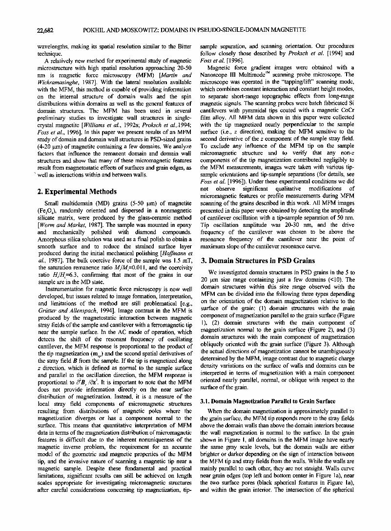
Figure 4. (a) Atomic force image of the magnetite grain in Figure 1 showing the shape of the grain and its surface topography. (b) MFM image of the same grain after low- temperature (77 K) demagnetization.
180 ø through a direction parallel to an intermediate [110] anisotropy axis within the surface. These 180 ø walls are parallel to (110) and (112) planes, which are the preferred 180 ø wall orientations for cubic materials with negative magneto- crystalline anisotropy such as magnetite [Lilley, 1950]. Therefore the energy density in these types of walls is lower than for other possible 180 ø walls that could form in this grain. A similar model of body domain structure was suggested by Paxton and Nilan [ 1955] for textured silicon iron.
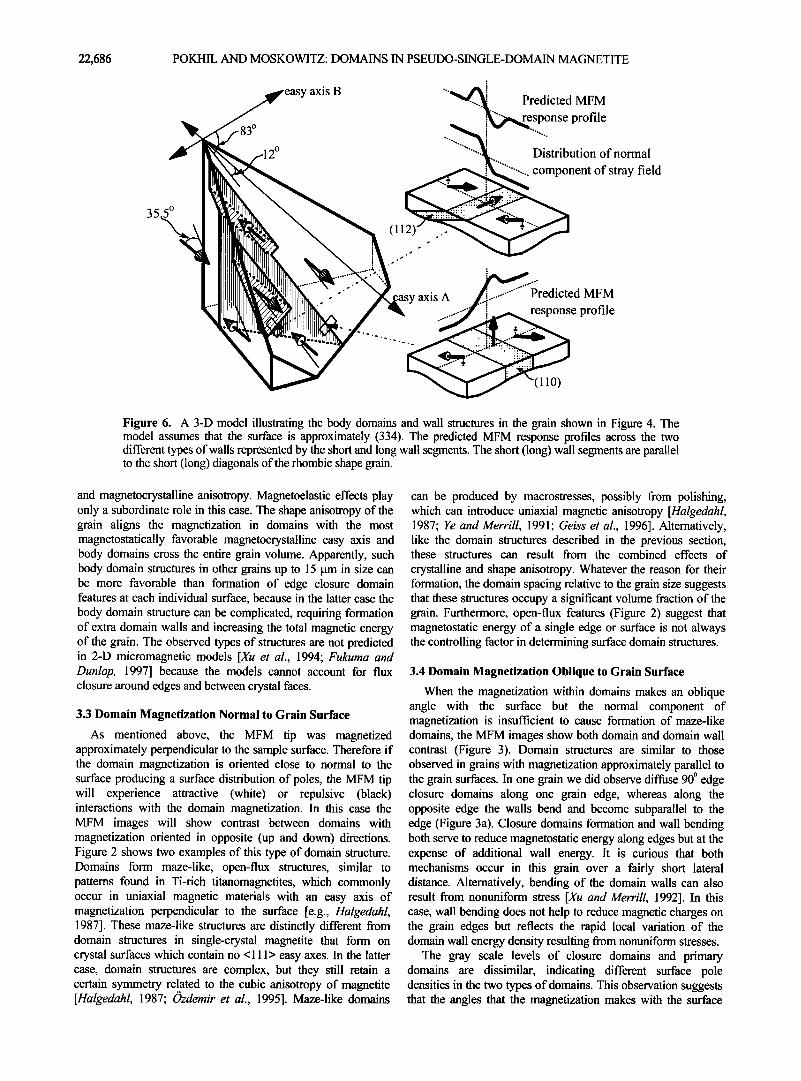
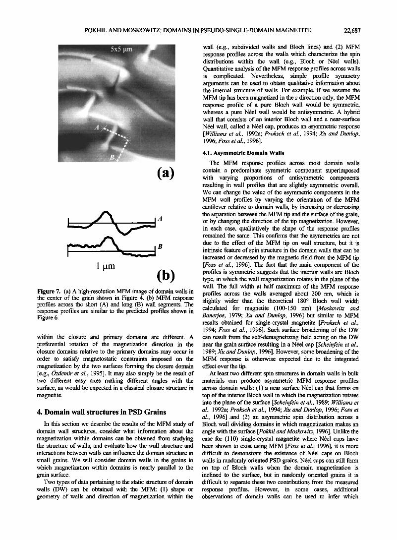
Besides the surface domain strucuture, the MFM response profiles across the walls also support this 3-D model. A high- resolution MFM image of step-like walls in the center of the grain and two MFM wall profiles taken across the short (profile A) and long (profile B) wall segments are shown in Figure 7. Using a simple charge stripe model for the two types of walls, the normal component of stray fields across the short segments of walls will produce a purely antisymmetric profile (Figure 6), whereas stray fields across the long segments of walls will produce an asymmetric profile combining both symmetric and antisymmetric components [Pokhil and Moskowitz, 1996]. Qualitatively, the model profiles reproduce the asymmetries observed in the MFM wall profiles (Figure 7b).
We conclude from our analysis of the domain structure in Figure 4b that the remanent body domain structures in this particular grain result from a combined volume magnetostatic effect of all grain surfaces (the shape anisotropy of the grain)
180 ø domain walls have a step-like structure in the body of the grain because this produces a better mixing of magnetic charges on the side surfaces of the grain, where the magnetization intersects the surface at a high (35.5 ø) angle. Wall segments exhibited two orientations having the lowest wall energy densities. Long segments of walls which are parallel to the long diagonal of the rhomb have wall planes close to parallel to a (110) plane normal to the surface. In this type of wall, magnetization rotates 180 ø across the wall from one direction parallel to easy axis A (closest to the surface) to the opposite direction, passing through a direction parallel to another easy axis B, which is close to the surface normal. The energy density of such a wall will be reduced because the spins rotate through an easy axis, where anisotropy energy would approach a minimum value [Lilley, 1950]. However, the wall does not separate into two 90 ø walls because either magnetoelastic or surface magnetostatic energy is sufficient to prevent this breakup [Scheinfein et al., 1990]. In the short segments of the walls, which are parallel to the short diagonal of the rhomb, the wall plane is inclined to the surface and magnetization rotates
(b)
(334)
Figure 5. Two possible crystallographic orientations of the grain shown in Figure 4 based on an initial (a) octahedron-shaped morphology resulting in a (110) cut surface and (b) cube-shaped morphology resulting in an approximately (334) cut surface.
22,686 POKHIL AND MOSKOWITZ: DOMAINS IN PSEUDO-SINGLE-DOMAIN MAGNETITE
83 ø
2 ø
easy axis B '"•.. Predicted MFM ! '"'"••e..s...p...onse pro file
Distribution of normal
.......... component of stray field
35.5 ø (l121
.-"' ',asy axis A Predicted MFM e profile
Figure 6. A 3-D model illustrating the body domains and wall structures in the grain shown in Figure 4. The model assumes that the surface is approximately (334). The predicted MFM response profiles across the two different types of walls represented by the short and long wall segments. The short (long) wall segments are parallel to the short (long) diagonals of the rhombic shape grain.
and magnetocrystalline anisotropy. Magnetoelastic effects play only a subordinate role in this case. The shape anisotropy of the grain aligns the magnetization in domains with the most magnetostatically favorable magnetocrystalline easy axis and body domains cross the entire grain volume. Apparently, such body domain structures in other grains up to 15 [tm in size can be more favorable than formation of edge closure domain features at each individual surface, because in the latter case the body domain structure can be complicated, requiring formation of extra domain walls and increasing the total magnetic energy of the grain. The observed types of structures are not predicted in 2-D micromagnetic models [Xu et al., 1994; Fukuma and Dunlop, 1997] because the models cannot account for flux closure around edges and between crystal faces.
3.3 Domain Magnetization Normal to Grain Surface
As mentioned above, the MFM tip was magnetized approximately perpendicular to the sample surface. Therefore if the domain magnetization is oriented close to normal to the surface producing a surface distribution of poles, the MFM tip will experience attractive (white) or repulsive (black) interactions with the domain magnetization. In this case the MFM images will show contrast between domains with magnetization oriented in opposite (up and down) directions. Figure 2 shows two examples of this type of domain structure. Domains form maze-like, open-flux structures, similar to patterns found in Ti-rich titanomagnetites, which commonly occur in uniaxial magnetic materials with an easy axis of magnetization perpendicular to the surface [e.g., Halgedahl, 1987]. These maze-like structures are distinctly different from domain structures in single-crystal magnetite that form on crystal surfaces which contain no < 111 > easy axes. In the latter case, domain structures are complex, but they still retain a certain symmetry related to the cubic anisotropy of magnetite [Halgedahl, 1987; Ozdemir et al., 1995]. Maze-like domains
can be produced by macrostresses, possibly from polishing, which can introduce uniaxial magnetic anisotropy [Halgedahl, 1987; Ye and Merrill, 1991; Geiss et al., 1996]. Alternatively, like the domain structures described in the previous section, these structures can result from the combined effects of
crystalline and shape anisotropy. Whatever the reason for their formation, the domain spacing relative to the grain size suggests that these structures occupy a significant volume fraction of the grain. Furthermore, open-flux features (Figure 2) suggest that magnetostatic energy of a single edge or surface is not always the controlling factor in determining surface domain structures.
3.4 Domain Magnetization Oblique to Grain Surface
When the magnetization within domains makes an oblique angle with the surface but the normal component of magnetization is insufficient to cause formation of maze-like domains, the MFM images show both domain and domain wall contrast (Figure 3). Domain structures are similar to those observed in grains with magnetization approximately parallel to the grain surfaces. In one grain we did observe diffuse 90 o edge closure domains along one grain edge, whereas along the opposite edge the walls bend and become subparallel to the edge (Figure 3a). Closure domains formation and wall bending both serve to reduce magnetostatic energy along edges but at the expense of additional wall energy. It is curious that both mechanisms occur in this grain over a fairly short lateral distance. Alternatively, bending of the domain walls can also result from nonuniform stress [Xu and Merrill, 1992]. In this case, wall bending does not help to reduce magnetic charges on the grain edges but reflects the rapid local variation of the domain wall energy density resulting from nonuniform stresses.
The gray scale levels of closure domains and primary domains are dissimilar, indicating different surface pole densities in the two types of domains. This observation suggests that the angles that the magnetization makes with the surface
POKHIL AND MOSKOWITZ: DOMAINS IN PSEUDO-SINGLE-DOMAIN MAGNETITE 22,687
(a)
,4
(b) Figure 7. (a) A high-resolution MFM image of domain walls in the center of the grain shown in Figure 4. (b) MFM response profiles across the short (A) and long (B) wall segments. The response profiles are similar to the predicted profiles shown in Figure 6.
within the closure and primary domains are different. A preferential rotation of the magnetization direction in the closure domains relative to the primary domains may occur in order to satisfy magnetostatic constraints imposed on the magnetization by the two surfaces forming the closure domain [e.g., Ozdemir et al., 1995]. It may also simply be the result of two different easy axes making different angles with the surface, as would be expected in a classical closure structure in magnetite.
4. Domain wall structures in PSD Grains
In this section we describe the results of the MFM study of domain wall structures, consider what information about the magnetization within domains can be obtained from studying the structure of Walls, and evaluate how the wall structure and interactions between walls can influence the domain structure in
small grains. We will consider domain walls in the grains in which magnetization within domains is nearly parallel to the grain surface.
Two types of data pertaining to the static structure of domain walls (DW) can be obtained with the MFM: (1) shape or geometry of walls and direction of magnetization within the
wall (e.g., subdivided walls and Bloch lines) and (2) MFM response profiles across the walls which characterize the spin distributions within the wall (e.g., Bloch or N6el walls). Quantitative analysis of the MFM response profiles across walls is complicated. Nevertheless, simple profile symmetry arguments can be used to obtain qualitative information about the internal structure of walls. For example, if we assume the MFM tip has been magnetized in the z direction only, the MFM response profile of a pure Bloch wall would be symmetric, whereas a pure N6el wall would be antisymmetric. A hybrid wall that consists of an interior Bloch wall and a near-surface
N6el wall, called a N6el cap, produces an asymmetric response [ Williams et al.. 1992a; Proksch et al., 1994; Xu and Dunlop, 1996; Foss et al., 1996].
4.1. Asymmetric Domain Walls
The MFM response profiles across most domain walls contain a predominate symmetric component superimposed with varying proportions of antisymmetric components resulting in wall profiles that are slightly asymmetric overall. We can change the value of the asymmetric components in the MFM wall profiles by varying the orientation of the MFM cantilever relative to domain walls, by increasing or decreasing the separation between the MFM tip and the surface of the grain, or by changing the direction of the tip magnetization. However, in each case, qualitatively the shape of the response profiles remained the same. This confirms that the asymmetries are not due to the effect of the MFM tip on wall structure, but it is intrinsic feature of spin structure in the domain walls that can be increased or decreased by the magnetic field from the MFM tip [Foss et al., 1996]. The fact that the main component of the profiles is symmetric suggests that the interior walls are Bloch type, in which the wall magnetization rotates in the plane of the wall. The full width at half maximum of the MFM response profiles across the walls averaged about 200 nm, which is slightly wider than the theoretical 180 ø Bloch wall width calculated for magnetite (100-150 nm) [Moskowitz and Banerjee, 1979; Xu and Dunlop, 1996] but similar to MFM results obtained for single-crystal magnetite [Proksch et al., 1994; Foss et al., 1996]. Such surface broadening of the DW can result from the self-demagnetizing field acting on the DW near the grain surface resulting in a N•el cap [Scheinfein et al., 1989; Xu and Dunlop, 1996]. However, some broadening of the MFM response is otherwise expected due to the integrated effect over the tip.
At least two different spin structures in domain walls in bulk materials can produce asymmetric MFM response profiles across domain walls: (1) a near surface N6el cap that forms on top of the interior Bloch wall in which the magnetization rotates into the plane of the surface [Scheinfein et al., 1989; Williams et al., 1992a; Proksch et al., 1994; Xu and Dunlop, 1996; Foss et al., 1996].and (2) an asymmetric spin distribution across a Bloch wall dividing domains in which magnetization makes an angle with the surface [Pokhil and Moskowitz, 1996]. Unlike the case for (110) single-crystal magnetite where N6el caps have been shown to exist using MFM [Foss et al., 1996], it is more difficult to demonstrate the existence of N6el caps on Bloch walls in randomly oriented PSD grains. N6el caps can still form on top of Bloch walls when the domain magnetization is inclined to the surface, but in randomly oriented grains it is difficult to separate these two contributions from the measured response profiles. However, in some cases, additional observations of domain walls can be used to infer which

22,688 POKHIL AND MOSKOWITZ: DOMAINS IN PSEUDO-SINGLE-DOMAIN MAGNETITE
mechanism is more likely responsible for asymmetric wall structures. For instance, we have observed small offsets of asymmetric domain walls in PSD magnetite grains, which suggested that in these particular grains the asymmetric wall structure was mainly due to inclined magnetization in adjacent domains rather then Nbel caps [Pokhil and Moskowitz, 1996].
4.2. Subdivided Domain Walls and Bloch Lines
Many walls in the PSD grains are subdivided into opposite polarity segments separated by narrow transitional regions called Bloch lines (Figure 8) [Shtrikman and Treves, 1960; Dunlop, 1977]. This observation is the first experimental confirmation that Bloch lines form in small particles of magnetite. The change in wall polarity across Bloch lines reduces the magnetostatic energy of the wall arising from its termination at the surface. Smallest observed distances between
Bloch lines in PSD grains are less then 1 pm, and some walls contain no Bloch lines at all. There is also no apparent periodicity in the location of Bloch lines along individual walls.
(c) .
20ø_ 40 ø
Figure 8. (a) and (b) MFM images of subdivided domain walls in magnetite grains. The black and white segments within the walls correspond to opposite polarity Bloch wall segments. The walls zigzag at the location of Bloch lines with zigzag angles of 200-40 ø. (c) Schematic diagram showing the distribution of surface domain wall charges and volume charges on the interior wall planes produced by the domain magnetization. See text for explanation.
All subdivided walls have a zigzag structure (Figures 8a and 8b), where the kinks of the zigzags are locations of Bloch lines [Shtrikman and Treves, 1960]. The zigzagging structure, in addition to wall segmentation, further minimizes the magnetostatic energy of the walls. Opposite polarity sections of the walls between Bloch lines attract each other and would
collapse upon themselves if not for the additional volume magnetic charges forming on the sides of the wall when the wall makes an angle with the magnetization within the domains (Figure 8c). The density of the volume charges increases with the angle between the wall and domain magnetization, thus increasing the magnetostatic energy of the system. Therefore the zigzag angles between wall segments represent an equilibrium configuration minimizing surface and volume magnetostatic effects.
The zigzag angles measured in the PSD grains are 20 ø to 40 ø and are significantly larger than the 30-5 ø angles measured between segments of a subdivided 180 ø wall in (110) single- crystal magnetite (Foss et al., Domain wall structures in single- crystal magnetite investigated by magnetic force microscopy, submitted to Journal of Geophysical Research, 1997). This observation can be explained as follows. MFM results show that wall widths in the PSD grains are similar in size to those observed in bulk single crystal magnetite [Proksch et al., 1994], but in a large single crystal, the surface area of an interior wall is larger than in small grains. Thus if a wall makes an angle with the domain magnetization, which produces a certain charge density on the sides of the wall, the total volume charge on the wall will be much higher in a large crystal than that in a small grain. Hence the zigzag angles are larger in PSD grains in order to achieve the same volume magnetic charge on the wall sides to offset the wall surface charge. In addition, the amplitude of wall zig-zagging (0.5-1 pm) is comparable to the size of the grains (Figures 8a and 8b), suggesting that the zigzag wall structure penetrates the entire grain. Hence the magnetostatic interactions within walls, which cause the wall zigzagging, also result in significant changes in body domain structure of the grains.
4.3. Bloch Line Nucleation and Translation
Changes in the remanent domain and domain wall structures were studied by imaging remanent magnetic states after exposing the grains to DC fields, AF fields, and low- temperature (77 K) demagnetization. MFM images of various remanent magnetic states of a single grain (Figure 9) reveal that Bloch lines nucleated and pinned at different locations along a particular wall, resulting in several different magnetic states for the same wall. Further, the number of Bloch lines per wall appears to be independent of the domain state. This is the first experimental evidence suggesting that LEM states exist for walls, as well as for domains [Moon and Merrill, 1985].
We also observed that Bloch lines could be nucleated in a
wall during displacement of the wall after exposure to an external magnetic field (Figure 10). For instance, a pair of Bloch lines were nucleated in the domain wall marked as DW I
during displacement of the wall in a 13 mT field (Figure 10). Bloch lines probably nucleate where the wall crosses defects or scratches around which there is a nonuniform spin distribution (Figures 10a and 10b). We also observed that after wall displacement, Bloch lines were displaced along the wall. The direction of the Bloch line displacement depends on the Bloch line chirality and direction of wall displacement. For instance, the Bloch line (BL I) in the domain wall marked as DW I

POKHIL AND MOSKOWITZ: DOMAINS IN PSEUDO-SINGLE-DOMAIN MAGNETITE 22,689
:!? --•'::•i: '.?..::.'-"' .: ':gi' 9%
..•
:.
:.. f.... ..... :..:.....: . .
.. :
::..
.
Figure 9. MFM images of various remanent magnetic states of a magnetite grain: (a) and (b) 100 mT AF demagnetized states, (c) and (d) 1.0 T saturation induced remanent magnetization (SIRM) states, and (e) low- temperature demagnetized (LTD) state. The LTD state was obtained by cooling the sample in liquid nitrogen and warming to room temperature in zero field. The arrows show the direction of applied field for each state.
(Figure 10) moves to the left when the domain wall moves down (Figures 10a and 10b) but moves to the right when the wall moves up (Figures 10b and 10c). Such behavior of Bloch lines was observed earlier in uniaxial materials and results from
dynamic effects arising from gyrotropic forces acting on Bloch lines in a moving domain wall [Slonczews/d and Malozemoff, 1978].
Finally, we observed that there are some favorable locations for Bloch lines in a wall. However, displacement of Bloch lines along the wall during wall translation is not always a reversible process, and Bloch lines can be pinned at different wall locations. Thus wall displacement can change the wall structure and influence the domain structure not just by changing wall position, but also by changing the wall configuration (i.e., changing zigzag wall structure).
4.4. Magnetostatic Interactions between Domain Walls
The formation of remanent domain structures in PSD grains is influenced not only by interactions within walls but also by interactions between walls. In many grains in the 10-15 [tm size range, the direction of magnetization in adjacent walls alternates across the grain. In a typical MFM image, this is seen as an alternating contrast between adjacent domain walls (Figures 1 and 11). If walls are subdivided, then adjacent segments in two adjacent walls can also have opposite magnetizations (Figure 11). Furthermore, the direction of magnetization within a domain and the neighboring domain walls are correlated. The direction of magnetization within the "in plane" domains can be determined by looking at the stray field configurations near the edges of the grain or above scratches and nonmagnetic
22,690 POKHIL AND MOSKOWITZ: DOMAINS IN PSEUDO-SINGLE-DOMAiN MAGNETITE
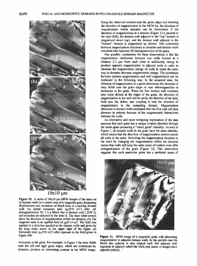
Figure 10. A series of 10xl 0 [tm MFM images of the same set of domain walls in a central area of a magnetite grain illustrating displacement and nucleation of Bloch lines in a moving domain wall. (a) Initial remanent state (itoH=0 mT) after AF demagnetization. BL I is a Bloch line in domain wall I (DW I), and scratches are denoted by the letter S. The short white arrows show the direction of magnetization within the domains. (b) The magnetic state in an applied field of [t0H=13 mT. The field was applied in a direction parallel to the domain walls and given by the long white arrow in the upper right of the figure. (c) Remanent state ([t0H=0 mT) after exposure to the field given in Figure 10b.
inclusions in the grain. For example, in Figure 1 the stray fields near the left and right grain edges, which are intersected by domains, produce an alternating contrast in the MFM image.
Using the observed contrast near the grain edges and knowing the direction of magnetization in the MFM tip, the direction of magnetization within domains can be determined. If the direction of magnetization in a domain (Figure 1) is pointed to the right (left), the domain wall adjacent to the "top" domain is magnetized down (up), and the domain wall adjacent to the "bottom" domain is magnetized up (down). This correlation between magnetization directions in domains and domain walls remained after repeated AF demagnetization of the grain.
One possible explanation for these observations is that the magnetostatic interaction between two walls located at a distance 2-3 pm from each other is sufficiently strong to produce opposite magnetization in adjacent walls in order to decrease the magnetostatic energy of walls in much the same way as domains decrease magnetostatic energy. The correlation between domain magnetization and wall magnetization can be explained in the following way. In the saturated state, the direction of magnetization in a grain determines the direction of stray fields near the grain edges or near inhomogeneities or inclusions in the grain. When the first domain wall nucleates near some defects at the edges of the grain, the direction of magnetization in the wall will be set by the direction of the stray field near the defect, and coupling it with the direction of magnetization in the expanding domain. Magnetization directions in domain walls nucleated after the first wall will then
alternate in polarity because of the magnetostatic interactions between the walls.
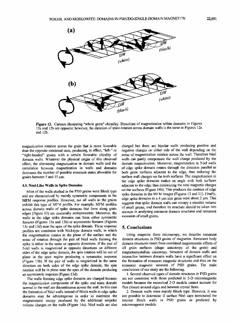
An alternative and more intriguing explanation of the data assumes that each grain has a unique rotation direction through the entire grain producing a "whole grain" chiraility. As seen in Figure 1, all domain walls in the grain have the same chirality, which means that the direction of magnetization rotation across all walls is the same. Switching the magnetization direction in the walls by changing the magnetization within the domains means that walls still keep the same sense of rotation even after remagnetization of the grain (Figure 12). This observation suggests that each particular grain has a preferred sense of
Figure 11. MFM image of a magnetite grain with alternating magnetization in adjacent domain walls. In this particle case the Bloch line polarity is also aligned such that adjacent wall segments in adjacent subdivide walls (top center of image) have opposite polarity. ø
POKHIL AND MOSKOWITZ: DOMAINS IN PSEUDO-SINGLE-DOMAIN MAGNETITE 22,691
(a)
(white)
black)
(b)
(btaclO
(white)
Figure 12. Cartoon illustrating "whole grain" chiraility. Directions of magnetization within domains in Figures 12a and 12b are opposite; however, the direction of spins rotation across domain walls is the same in Figures 12a and 12b.
magnetization rotation across the grain that is more favorable than the opposite rotational state, producing, in effect, "left-" or "right-handed" grains with a certain favorable chirality of domain walls. Whatever the physical origin of this observed effect, the alternating magnetization in domain walls and the correlation between magnetization in walls and domains decreases the number of possible remanent states allowable for grains between 5 and 15 gm.
4.5. N/•el-Like Walls in Spike Domains
Most of the walls studied in the PSD grains were Bloch type and are characterized by mainly symmetric components in the MFM response profiles. However, not all walls in the grains exhibit this type of MFM profile. For example, MFM profiles across domain walls of spike domains that form along grain edges (Figure 13) are essentially antisymmetric. Moreover, the walls in the edge spike domains can form either symmetric features (Figures 13a and 13b) or asymmetric features (Figures 13c and 13d) near the apex of the spike domain. These response profiles are consistent with Ndel-type domain walls, in which the magnetization rotates in the plane of the surface and the sense of rotation through the pair of N•el walls forming the spike is either in the same or opposite directions. If the pair of Ndel walls is magnetized in opposite directions on different sides of the edge spike domain, the spin rotation will be out of plane in the apex region producing a symmetric response (Figure 13b). If the pair of walls is magnetized in the same direction on both sides of the edge spike domain, the spin rotation will be in plane near the apex of the domain producing an asymmetric response (Figure 13d).
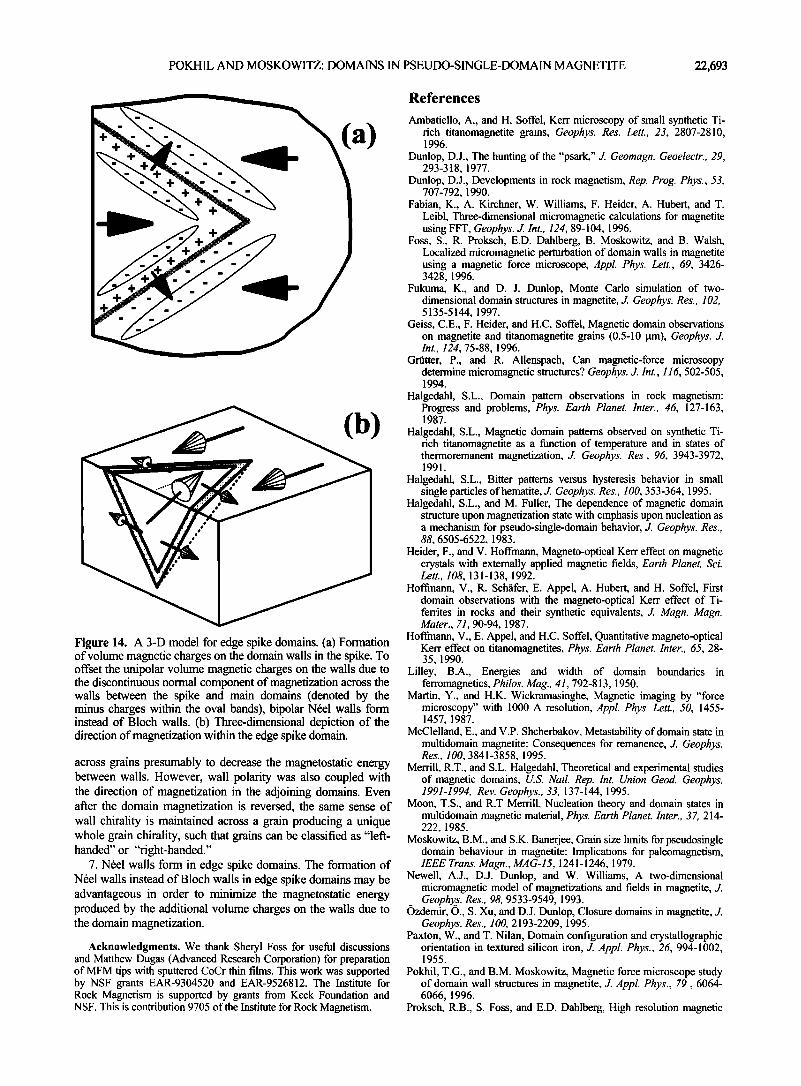
The walls forming edge spike domains are charged because the magnetization components of the spike and main domain normal to the wall are discontinuous across the wall. In this case the formation of N•el walls instead of Bloch walls in edge spike domains may be advantageous in order to minimize the magnetostatic energy produced by the additional unipolar volume charges on the walls (Figure 14a). N•el walls are also
charged but there are bipolar walls producing positive and negative charges on either side of the wall depending on the sense of magnetization rotation across the wall. Therefore N•el walls can partly compensate the wall charge produced by the domain magnetization. Moreover, magnetization in N•el walls of edge spike domain rotates through the direction parallel to both grain surfaces adjacent to the edge, thus reducing the surface wall charges on the both surfaces. The magnetization in the edge spike domains makes an angle with both surfaces adjacent to the edge thus minimizing the total magnetic charges on the surfaces (Figure 14b). This produces the contrast of edge spike domains in the MFM images (Figures 13 and 11). Finally, edge spike domains in a 4 gm size grain were about 2 gm. This suggests that spike domain walls can occupy a sizeable volume of small grains, and therefore its structure should be taken into account in analyzing remanent domain structures and remanent moments of small grains.
5. Conclusions
Using magnetic force microscopy, we describe remanent domain structures in PSD grains of magnetite. Remanent body domain structures result from combined magnetostatic effects of all grain surfaces (shape anisotropy of the grain) and magnetocrystalline anisotropy. Structure of domain walls and interaction between domain walls have a significant effect on the formation of remanent magnetic structures and thus on the remanent magnetic moment of PSD grains. The main conclusions of our study are the following.
1. Several observed types of domain structures in PSD grains are not consistent with those predicted in 2-D micromagnetic models because the numerical 2-D models cannot account for
flux closure around edges and between crystal faces. 2. Domain walls were mainly Bloch type. However, it was
not possible to determine if surface N•el caps terminated the interior Bloch walls in PSD grains as predicted by micromagnetic models.

22,692 POKHIL AND MOSKOWITZ: DOMAINS IN PSEUDO-SINGLE-DOMAIN MAGNETITE
•,•e of the grain :'• *•'*•"• • '•"•iiiii•'•,::' $?•:----:..--.2{'"5i•': ' ........... ' ............................... :"'•:':•'•"'•'•'---
:•ii.-"'-'•i}•;.+':•ilili ............. •i::il ............. •!ii•i::ø;?•i•i .
0.75
B
C
Figure 13. (a) MFM image of edge spike domain and MFM response profiles across the apex of the spike (profile A) and across the wall forming one side of the spike domain (profile B). This type of spike domain produces a symmetric feature near the apex of the spike where the magnetization rotates out of plane. (b) Schematic diagram showing the spin distribution in the N6el walls forming the spike domain in Figure 13a. (c) MFM image of a edge spike domain and MFM response profile across the spike domain wall (profile C). This type of spike domain produces an asymmetric feature near the apex of the spike where the magnetization rotates in plane. (d) Schematic diagram showing the spin distribution in the N6el walls forming the spike domain in Figure 13c.
3. Domain wails are frequently subdivided into two or three opposite polarity segments separated by Bloch lines. Occasionally, some walls are unipolar, containing no Bloch lines. We also observe that after wall displacement by an external field, Bloch lines are also displaced along the wall. The direction of the Bloch line displacement depends on the Bloch line chirality and direction of wall displacement.
4. Domain walls zigzag at the location of Bloch lines to decreases the magnetostatic energy of subdivided walls. Many domain walls display some degree of curvature, which may help
to decrease the free magnetic charges when it occurs near grain edges. However, wall bending can also be a result of nonuniform stress in the grains.
5. Bloch lines can be nucleated or denucleated during wall displacement or after repeated AF demagnetization. In addition, the number of Bloch lines and their pinning locations along individual walls can vary after repeated AF demagnetization, resulting in different remanent magnetic states of the same wall. Therefore domain walls can exist in different LEM states.
6. Wall polarity alternates in sign between adjacent walls
POKHIL AND MOSKOWITZ: DOMAINS IN PSEUDO-SINGLE-DOMAIN MAGNETITE 22,693
(a)
(b)
Figure 14. A 3-D model for edge spike domains. (a) Formation of volume magnetic charges on the domain walls in the spike. To offset the unipolar volume magnetic charges on the walls due to the discontinuous normal component of magnetization across the walls between the spike and main domains (denoted by the minus charges within the oval bands), bipolar N•el walls form instead of Bloch walls. (b) Three-dimensional depiction of the direction of magnetization within the edge spike domain.
across grains presumably to decrease the magnetostatic energy between walls. However, wall polarity was also coupled with the direction of magnetization in the adjoining domains. Even after the domain magnetization is reversed, the same sense of wall chirality is maintained across a grain producing a unique whole grain chirality, such that grains can be classified as "left- handed" or "right-handed."
7. N•el walls form in edge spike domains. The formation of N•el walls instead of Bloch walls in edge spike domains may be advantageous in order to minimize the magnetostatic energy produced by the additional volume charges on the walls due to the domain magnetization.
Acknowledgments. We thank Sheryl Foss for useful discussions and Matthew Dugas (Advanced Research Corporation) for preparation of MFM tips with sputtered CoCr thin films. This work was supported by NSF grants EAR-9304520 and EAR-9526812. The Institute for Rock Magnetism is supported by grants from Keck Foundation and NSF. This is contribution 9705 of the Institute for Rock Magnetism.
References
Ambatiello, A., and H. Soffel, Kerr microscopy of small synthetic Ti- rich titanomagnetite grains, Geophys. Res. Lett., 23, 2807-2810, 1996.
Dunlop, D.J., The hunting of the "psark," d. Geomagn. Geoelecm, 29, 293-318, 1977.
Dunlop, D.J., Developments in rock magnetism, Rep. Prog. Phys., 53, 707-792, 1990.
Fabian, K., A. Kirchner, W. Williams, F. Heider, A. Hubert, and T. Leibl, Three-dimensional micromagnetic calculations for magnetite using FFT, Geophys. d. Int., 124, 89-104, 1996.
Foss, S., R. Proksch, E.D. Dahlberg, B. Moskowitz, and B. Walsh, Localized micromagnetic perturbation of domain walls in magnetite using a magnetic force microscope, Appl. Phys. Lett., 69, 3426- 3428, 1996.
Fukuma, K., and D. J. Dunlop, Monte Carlo simulation of two- dimensional domain structures in magnetite, d. Geophys. Res., 102, 5135-5144, 1997.
Geiss, C.E., F. Heider, and H.C. Soffel, Magnetic domain observations on magnetite and titanomagnetite grains (0.5-10 •tm), Geophys. d. Int., 124, 75-88, 1996.
Grfitter, P., and R. Allenspach, Can magnetic-force microscopy determine micromagnetic structures? Geophys. d. Int., 116, 502-505, 1994.
Halgedahl, S.L., Domain pattem observations in rock magnetism: Progress and problems, Phys. Earth Planet. Inter., 46, 127-163, 1987.
Halgedahl, S.L., Magnetic domain pattems observed on synthetic Ti- rich titanomagnetite as a function of temperature and in states of thermoremanent magnetization, d. Geophys. Res., 96, 3943-3972, 1991.
Halgedahk S.L., Bitter pattems versus hysteresis behavior in small single particles of hematite, J. Geophys. Res., 100, 353-364, 1995.
Halgedahl, S.L., and M. Fuller, The dependence of magnetic domain structure upon magnetization state with emphasis upon nucleation as a •nechanism for pseudo-single-domain behavior, d. Geophys. Res., 88, 6505-6522, 1983.
Heider, F., and V. Hoffmann, Magneto-optical Kerr effect on magnetic crystals with extemally applied magnetic fields, Earth Planet. Sci. Lett., 108, 131-138, 1992.
Hoffmann, V., R. Schfifer, E. Appel, A. Hubert, and H. Soffel, First domain observations with the magneto-optical Kerr effect of Ti- ferrites in rocks and their synthetic equivalents, J. Magn. Magn. Mater., 71, 90-94, 1987.
Hoffinann, V., E. Appel, and H.C. Soffel, Quantitative magneto-optical Kerr effect on titanomagnetites, Phys. Earth Planet. Inter., 65, 28- 35, 1990.
Lilley, B.A., Energies and width of domain boundaries in ferromagnetics, Philos. Mag., 41,792-813, 1950.
Martin, Y., and H.K. Wickramasinghe, Magnetic imaging by "force microscopy" with 1000 A resolution, Appl. Phys. Lett., 50, 1455- 1457, 1987.
McClelland, E., and V.P. Shcherbakov, Metastability of domain state in multidomain magnetite: Consequences for remanence, d. Geophys. Res., 100, 3841-3858, 1995.
Merrill, R.T., and S.L. Halgedahl, Theoretical and experimental studies of magnetic domains, U.S. Natl. Rep. Int. Union Geod. Geophys. 1991-1994, Rev. Geophys., 33, 137-144, 1995.
Moon, T.S., and R.T Merrill, Nucleation theory and domain states in multidomain magnetic material, Phys. Earth Planet. Inter., 37, 214- 222, 1985.
Moskowitz, B.M., and S.K. Banerjee, Grain size limits for pseudosingle domain behaviour in magnetite: hnplications for paleomagnetism, IEEE Trans. Magn., MAG-15, 1241-1246, 1979.
Newell, A.J., D.J. Dunlop, and W. Williams, A two-dimensional micromagnetic model of magnetizations and fields in magnetite, J. Geophy..s. Res., 98, 9533-9549, 1993.
Ozdemir, O., S. Xu, and D.J. Dunlop, Closure domains in magnetite, J. Geophys. Res., 100, 2193-2209, 1995.
Paxton, W., and T. Nilan, Domain configuration and crystallographic orientation in textured silicon iron, J. Appl. Phys., 26, 994-1002, 1955.
Pokhil, T.G., and B.M. Moskowitz, Magnetic force microscope study of domain wall structures in magnetite, J. Appl. Phys., 79,6064- 6066, 1996.
Proksch, R.B., S. Foss, and E.D. Dahlberg, High resolution magnetic

22,694 POKHIL AND MOSKOWITZ: DOMAINS IN PSEUDO-SINGLE-DOMAIN MAGNETITE
force microscopy of domain wall fine structures, IEEE Trans. Magn., MAG-30, 4467-4472, 1994.
Scheinfein, M.R., J. Unguris, R.J. Celotta, and D.T. Pierce, Influence of the surface on magnetic domain-wall microstructure, Phys. Rev. Lett., 63(6), 668-671, 1989.
Scheinfein, M.R., J. Unguris, D.T. Pierce, and R.J. Celotta, High spatial resolution quantitative micromagnetics, J. Appl. Phys., 67, 5932- 5937, 1990.
Shtfikrnan, S., and D. Treves, Fine structure of Bloch walls, d. Appl. Phys., 31, 147S-148S, 1960.
Slonczewski, J.C., and A.P. Malozemoff, Physics of domain walls in magnetic garnet films, in Physics of Magnetic Garnets, Proc. Int. Sch. Phys. Enrico Fermi, LXX, 134-195, 1978.
Soffel, H.C., The single domain-multidomain transition in natural intermediate titanomagnetite, Z. Geophys., 37, 451-470, 1971.
Thompson, L.C., R.J. Enkin, and W. Williams, Simulated annealing of three-dimensional micromagnetic structures and simulated thermoremanent magnetization, d. Geophys. Res., 99, 603-609, 1994.
Williams, W., and D.J. Dunlop, Simulation of magnetic hysteresis in pseudo-single-domain grains of magnetite, d. Geoph•vs. Res. 100, 3859-3871, 1995.
Williams, W., V. Hoffmann, F. Heider, T. G6ddenhenrich, and C. Heiden, Magnetic force microscopy imaging of domain walls in magnetite, Geophys. J. Int., 111, 417-423, 1992a.
Williams, W., R.J. Enkin, and G. Milne, Magnetic domain wall visibility in Bitter pattern imaging, J. Geophys. Res., 97, 17,433- 17,438, 1992b.
Worm, H.-U., and H. Markert, Magnetic hysteresis properties of fine particle titanomagnetites precipitated in a silicate matrix, Phys. Earth Planet. Inter., 46, 84-93, 1987.
Worm, H.-U., P.J. Ryan, and S.K. Banerjee, Domain size, closure domains, and the importance of magnetostriction in magnetite, Earth Planet. Sci. Lett., 102, 71-78, 1991.
Xu, S., D.J. Dunlop, and A.J. Newell, Micromagnetic modeling of two- dimensional domain structures in magnetite, d. Geophys. Res., 99, 9035-9044, 1994.
Xu, S., and D.J. Dunlop, Micromagnetic modeling of domain wall structures, Geophys. Res. Lett., 23, 2819-2822, 1996.
Xu, S., and R.T. Merrill, Stress, grain size, and magnetic stability of magnetite, J. Geophys. Res., 97, 4321-4329, 1992.
Ye, J., and R.T. Merrill, Differences between magnetic domain imaging observations and theory, Geopkvs. Res. Lett., 18, 593-596, 1991.
B. M. Moskowitz and T. G. Pokhil, Institute for Rock Magnetism, University of Minnesota, 291 Shepherd Laboratories, 100 Union St. S. E., Minneapolis, MN 55455-0128. (bmosk•maroon.tc.umn.edu; pokhi001 @gold.tc.umn.edu)
(Received February 3, 1997; revised June 13, 1997; accepted June 20, 1997)