Embed Size (px)
Citation preview
IPA/CPA SeriesMagnetic Circuit Protectors
• 83
• 84
• 87
• 89
• 90
• 91
• 93
• 95
Introduction
Poles
PC Board Mount
Configurations
Operating Characteristics
Delay Curves
Specifications
Decision Tables
INTRODUCTION
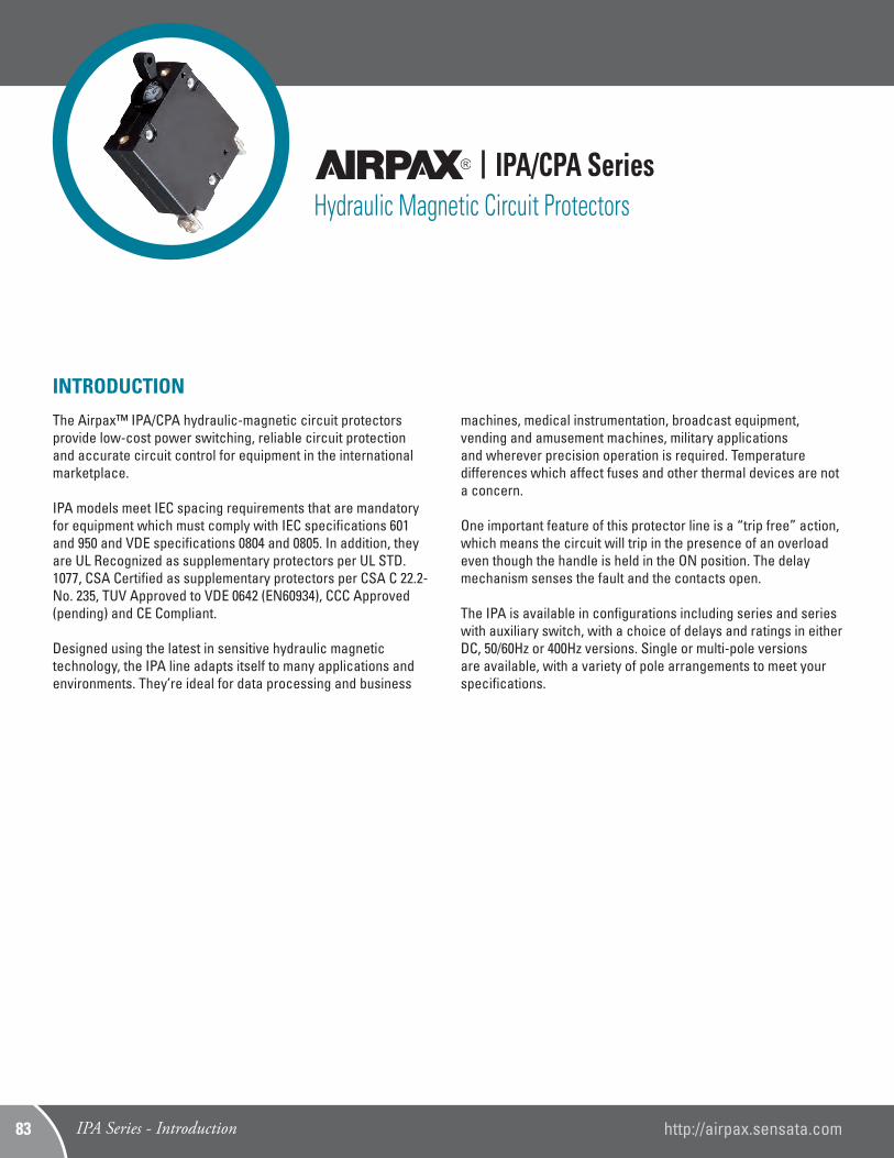
The Airpax™ IPA/CPA hydraulic-magnetic circuit protectors provide low-cost power switching, reliable circuit protection and accurate circuit control for equipment in the international marketplace.
IPA models meet IEC spacing requirements that are mandatory for equipment which must comply with IEC specifications 601 and 950 and VDE specifications 0804 and 0805. In addition, they are UL Recognized as supplementary protectors per UL STD. 1077, CSA Certified as supplementary protectors per CSA C 22.2-No. 235, TUV Approved to VDE 0642 (EN60934), CCC Approved (pending) and CE Compliant.
Designed using the latest in sensitive hydraulic magnetic technology, the IPA line adapts itself to many applications and environments. They’re ideal for data processing and business
machines, medical instrumentation, broadcast equipment, vending and amusement machines, military applications and wherever precision operation is required. Temperature differences which affect fuses and other thermal devices are not a concern. One important feature of this protector line is a “trip free” action, which means the circuit will trip in the presence of an overload even though the handle is held in the ON position. The delay mechanism senses the fault and the contacts open. The IPA is available in configurations including series and series with auxiliary switch, with a choice of delays and ratings in either DC, 50/60Hz or 400Hz versions. Single or multi-pole versions are available, with a variety of pole arrangements to meet your specifications.
IPA/CPA SeriesHydraulic Magnetic Circuit Protectors
IPA Series - Introduction http://airpax.sensata.com83
1.260[32.00]
.640 MAX.[16.26]
2X 6-32 THREAD.165 MAX.
[4.19]
.535[13.59]
1.654[42.01]
.982[24.94]
.228[5.79]
ON
OFF
1.732[43.99]
.098[2.49]
60
1.988 MAX.[50.50]
.635[16.13]
LINE
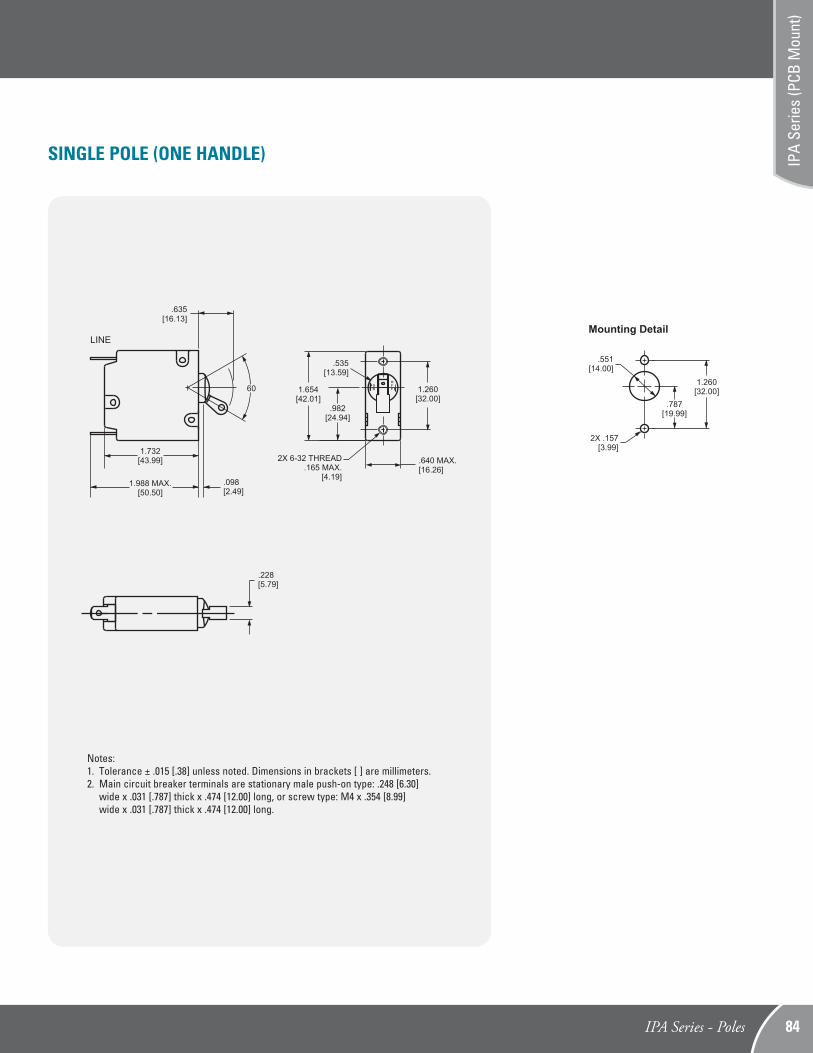
SINGLE POLE (ONE HANDLE)
Notes:1. Tolerance ± .015 [.38] unless noted. Dimensions in brackets [ ] are millimeters.2. Main circuit breaker terminals are stationary male push-on type: .248 [6.30] wide x .031 [.787] thick x .474 [12.00] long, or screw type: M4 x .354 [8.99] wide x .031 [.787] thick x .474 [12.00] long.
.787[19.99]
1.260[32.00]
.551[14.00]
2X .157 [3.99]
Mounting Detail
IPA Series - Poles 84
IPA
Serie
s (P
CB M
ount
)
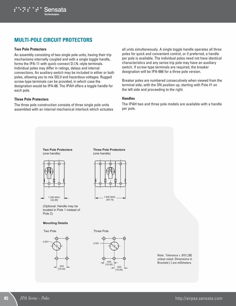
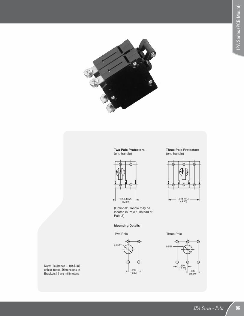
MULTI-POLE CIRCUIT PROTECTORS
Two Pole ProtectorsAn assembly consisting of two single pole units, having their trip mechanisms internally coupled and with a single toggle handle, forms the IPA-11 with quick-connect D.I.N.-style terminals. Individual poles may differ in ratings, delays and internal connections. An auxiliary switch may be included in either or both poles, allowing you to mix SELV and hazardous voltages. Rugged screw-type terminals can be provided, in which case the designation would be IPA-66. The IPAH offers a toggle handle for each pole.
Three Pole ProtectorsThe three pole construction consists of three single pole units assembled with an internal mechanical interlock which actuates
Note: Tolerance ± .015 [.38] unless noted. Dimensions in Brackets [ ] are millimeters.
1.295 MAX.[32.89]
ON
OFF
1.935 MAX.[49.15]
ON
OFF
.630[16.00]
.630[16.00]
.630[16.00]
0.551
Mounting Details
Two Pole Protectors(one handle)
IPA/CPA
Three Pole Protectors(one handle)
Two Pole Three Pole
0.551
(Optional: Handle may belocated in Pole 1 instead ofPole 2)
all units simultaneously. A single toggle handle operates all three poles for quick and convenient control, or if preferred, a handle per pole is available. The individual poles need not have identical characteristics and any series trip pole may have an auxiliary switch. If screw-type terminals are required, the breaker designation will be IPA-666 for a three pole version.
Breaker poles are numbered consecutively when viewed from the terminal side, with the ON position up, starting with Pole #1 on the left side and proceeding to the right.
HandlesThe IPAH two and three pole models are available with a handle per pole.
IPA Series - Poles http://airpax.sensata.com85
Note: Tolerance ± .015 [.38] unless noted. Dimensions in Brackets [ ] are millimeters.
1.295 MAX.[32.89]
ON
OFF
1.935 MAX.[49.15]
ON
OFF
.630[16.00]
.630[16.00]
.630[16.00]
0.551
Mounting Details
Two Pole Protectors(one handle)
IPA/CPA
Three Pole Protectors(one handle)
Two Pole Three Pole
0.551
(Optional: Handle may belocated in Pole 1 instead ofPole 2)
IPA Series - Poles 86
IPA
Serie
s (P
CB M
ount
)
[35.99]1.417
[3.99].157
[5.00].197
[8.00].315
[1.19].047
[13.59].535
[21.59].850
[5.00].197
[1.90]4X Ø.075
[0.80].031
[3.51].138
[12.50].492
[1.20].047
[45.49]1.791
[1.19].047
[5.00].197
[59.79]2.354
[0.51].020
[0.79].031
[3.51].138
[1.90]9X Ø.075 [12.50]
.492
[45.80]1.803
[59.99]2.362
[5.00].197
[21.59].850
[13.59].535
[11.71].461
[10.31].406
[6.10].240
HANDLECENTER
HANDLE CENTER
[6.25].246
[35.99]1.417
[3.01].118
[8.00].315
[42.01]1.654
[45.49]1.791
[1.19].047
[5.00].197
[59.79]2.354
[0.51].020
[0.79].031
[3.51].138
[0.80].031
[3.51].138
[12.50].492
[1.20].047
HANDLE CENTER
[1.90]
9X Ø.075
[45.80]1.803
[59.99]2.362
[5.00].197
[21.59].850
[13.59].535
[11.71].461
[10.31].406
[6.10].240
[12.50].492
[6.25].246
Mounting Detail
Mounting DetailMounting Detail
(Auxiliary switch is not recommendedwith this type mounting.)
OFF
ON
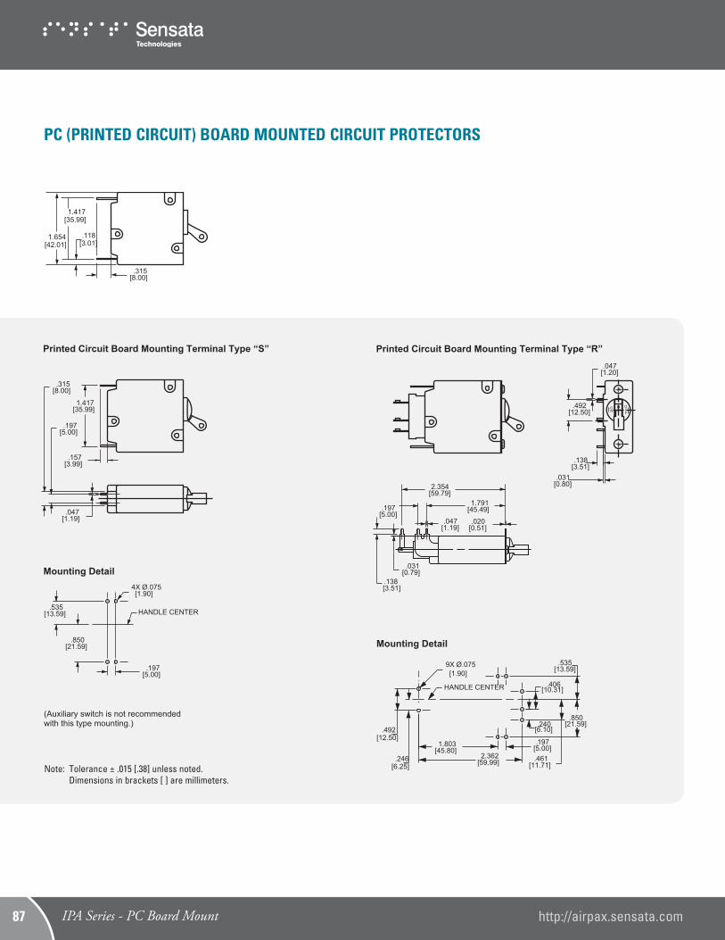
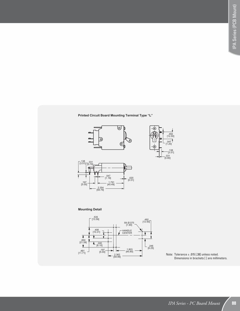
Printed Circuit Board Mounting Terminal Type “S” Printed Circuit Board Mounting Terminal Type “L”Printed Circuit Board Mounting Terminal Type “R”
OFF
ON
Note: Tolerance ± .015 [.38] unless noted. Dimensions in brackets [ ] are millimeters.
PC (PRINTED CIRCUIT) BOARD MOUNTED CIRCUIT PROTECTORS
IPA Series - PC Board Mount http://airpax.sensata.com87
[35.99]1.417
[3.99].157
[5.00].197
[8.00].315
[1.19].047
[13.59].535
[21.59].850
[5.00].197
[1.90]4X Ø.075
[0.80].031
[3.51].138
[12.50].492
[1.20].047
[45.49]1.791
[1.19].047
[5.00].197
[59.79]2.354
[0.51].020
[0.79].031
[3.51].138
[1.90]9X Ø.075 [12.50]
.492
[45.80]1.803
[59.99]2.362
[5.00].197
[21.59].850
[13.59].535
[11.71].461
[10.31].406
[6.10].240
HANDLECENTER
HANDLE CENTER
[6.25].246
[35.99]1.417
[3.01].118
[8.00].315
[42.01]1.654
[45.49]1.791
[1.19].047
[5.00].197
[59.79]2.354
[0.51].020
[0.79].031
[3.51].138
[0.80].031
[3.51].138
[12.50].492
[1.20].047
HANDLE CENTER
[1.90]
9X Ø.075
[45.80]1.803
[59.99]2.362
[5.00].197
[21.59].850
[13.59].535
[11.71].461
[10.31].406
[6.10].240
[12.50].492
[6.25].246
Mounting Detail
Mounting DetailMounting Detail
(Auxiliary switch is not recommendedwith this type mounting.)
OFF
ON
Printed Circuit Board Mounting Terminal Type “S” Printed Circuit Board Mounting Terminal Type “L”Printed Circuit Board Mounting Terminal Type “R”
OFF
ON
Note: Tolerance ± .015 [.38] unless noted. Dimensions in brackets [ ] are millimeters.
IPA Series - PC Board Mount 88
IPA
Serie
s (P
CB M
ount
)
[35.99]1.417
[3.99].157
[5.00].197
[8.00].315
[1.19].047
[13.59].535
[21.59].850
[5.00].197
[1.90]4X Ø.075
[0.80].031
[3.51].138
[12.50].492
[1.20].047
[45.49]1.791
[1.19].047
[5.00].197
[59.79]2.354
[0.51].020
[0.79].031
[3.51].138
[1.90]9X Ø.075 [12.50]
.492
[45.80]1.803
[59.99]2.362
[5.00].197
[21.59].850
[13.59].535
[11.71].461
[10.31].406
[6.10].240
HANDLECENTER
HANDLE CENTER
[6.25].246
[35.99]1.417
[3.01].118
[8.00].315
[42.01]1.654
[45.49]1.791
[1.19].047
[5.00].197
[59.79]2.354
[0.51].020
[0.79].031
[3.51].138
[0.80].031
[3.51].138
[12.50].492
[1.20].047
HANDLE CENTER
[1.90]
9X Ø.075
[45.80]1.803
[59.99]2.362
[5.00].197
[21.59].850
[13.59].535
[11.71].461
[10.31].406
[6.10].240
[12.50].492
[6.25].246
Mounting Detail
Mounting DetailMounting Detail
(Auxiliary switch is not recommendedwith this type mounting.)
OFF
ON
Printed Circuit Board Mounting Terminal Type “S” Printed Circuit Board Mounting Terminal Type “L”Printed Circuit Board Mounting Terminal Type “R”
OFF
ON
Notes:1. Main circuit protector terminals are stationary male push-on type: .248 [6.30] wide x .031 [.787] thick x .474 [12.00] long, or screw type: M4 x .354 [8.99] wide x .031 [.787] thick x .474 [12.00] long.2. Auxiliary switch terminals are: .110 [2.79] wide x .020 [0.51] thick x .343 [8.71] long.3. Tolerance ± .015 [.38] unless noted. Dimensions in brackets [ ] are millimeters.
[35.13]1.383
[25.77]1.015
[26.00]1.024
[9.58]
.377
C
NO
NC
LINE
LOAD
C
NO
NC
LINE
LOAD
LINE
LOAD
Series
C
[19.68].775
[9.37].369
[18.52].729 MAX.
NO
NC
[35.13]
1.383
[3.43]
.135
LINE
LOAD
Switch
LOAD
LINE
C
NO
NC
LINE
C-NC = Breaker in
“OFF” position.
Breaker in “ON” or manually
turned “OFF” position.Breaker in electrically tripped
“OFF” position.
Series withAuxiliary Switch
Auxiliary Alarm Switch (IRS4, IRSG4)
Series Trip
Series with Auxiliary Switch
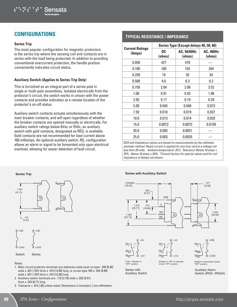
CONFIGURATIONS
Series TripThe most popular configuration for magnetic protectorsis the series trip where the sensing coil and contacts are in series with the load being protected. In addition to providing conventional overcurrent protection, the handle position conveniently indicates circuit status.
Auxiliary Switch (Applies to Series Trip Only)
This is furnished as an integral part of a series pole insingle or multi-pole assemblies. Isolated electrically from the protector’s circuit, the switch works in unison with the power contacts and provides indication at a remote location of the protector’s on-off status.
Auxiliary switch contacts actuate simultaneously with the main breaker contacts, and will open regardless of whether the breaker contacts are opened manually or electrically. For auxiliary switch ratings below 6Vac or 5Vdc, an auxiliary switch with gold contacts, designated as REG, is available. Gold contacts are not recommended for load current above 100 milliamps. An optional auxiliary switch, RS, configuration allows an alarm or signal to be forwarded only upon electrical overload, allowing for easier detection of fault circuit.
TYPICAL RESISTANCE / IMPEDANCE
Current Ratings (Amps)
Series Type (Except delays 40, 50, 60)
DC (ohms)
AC, 50/60Hz (ohms)
AC, 400Hz (ohms)
0.050 427 478 —
0.100 100 103 204
0.250 19 20 34
0.500 4.6 6.3 8.2
0.750 2.04 2.06 3.52
1.00 0.91 0.92 1.86
2.50 0.17 0.19 0.28
5.00 0.045 0.046 0.073
7.50 0.018 0.019 0.037
10.0 0.013 0.014 0.020
15.0 0.0072 0.0073 0.0109
20.0 0.005 0.0051 —
25.0 0.003 0.0035 —DCR and Impedance values are based on measurements by the voltmeter ammeter method. Rated current is applied for one hour and at a voltage not less than 20 volts. Ambient temperature: 25 C; Tolerance: Below 10 amps ± 25%; Above 10 amps ± 50%; *Consult factory for special values and for coil impedance of delays not shown.
[35.13]1.383
[25.77]1.015
[26.00]1.024
[9.58]
.377
C
NO
NC
LINE
LOAD
C
NO
NC
LINE
LOAD
LINE
LOAD
Series
C
[19.68].775
[9.37].369
[18.52].729 MAX.
NO
NC
[35.13]
1.383
[3.43]
.135
LINE
LOAD
Switch
LOAD
LINE
C
NO
NC
LINE
C-NC = Breaker in
“OFF” position.
Breaker in “ON” or manually
turned “OFF” position.Breaker in electrically tripped
“OFF” position.
Series withAuxiliary Switch
Auxiliary Alarm Switch (IRS4, IRSG4)
Series Trip
Series with Auxiliary Switch
IPA Series - Configurations http://airpax.sensata.com89
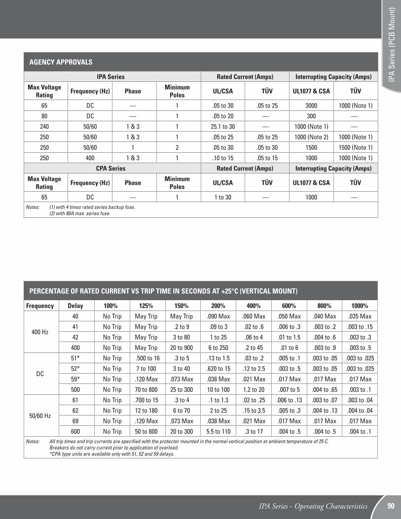
PERCENTAGE OF RATED CURRENT VS TRIP TIME IN SECONDS AT +25°C (VERTICAL MOUNT)
Frequency Delay 100% 125% 150% 200% 400% 600% 800% 1000%
400 Hz
40 No Trip May Trip May Trip .090 Max .060 Max .050 Max .040 Max .035 Max
41 No Trip May Trip .2 to 9 .09 to 3 .02 to .6 .006 to .3 .003 to .2 .003 to .15
42 No Trip May Trip 3 to 80 1 to 25 .06 to 4 .01 to 1.5 .004 to .6 .003 to .3
400 No Trip May Trip 20 to 900 6 to 250 .2 to 45 .01 to 6 .003 to .9 .003 to .5
DC
51* No Trip .500 to 16 .3 to 5 .13 to 1.5 .03 to .2 .005 to .1 .003 to .05 .003 to .025
52* No Trip 7 to 100 3 to 40 .620 to 15 .12 to 2.5 .003 to .5 .003 to .05 .003 to .025
59* No Trip .120 Max .073 Max .038 Max .021 Max .017 Max .017 Max .017 Max
500 No Trip 70 to 800 25 to 300 10 to 100 1.2 to 20 .007 to 5 .004 to .65 .003 to .1
50/60 Hz
61 No Trip .700 to 15 .3 to 4 .1 to 1.3 .02 to .25 .006 to .13 .003 to .07 .003 to .04
62 No Trip 12 to 180 6 to 70 2 to 25 .15 to 3.5 .005 to .3 .004 to .13 .004 to .04
69 No Trip .120 Max .073 Max .038 Max .021 Max .017 Max .017 Max .017 Max
600 No Trip 50 to 800 20 to 300 5.5 to 110 .3 to 17 .004 to .5 .004 to .5 .004 to .1Notes: All trip times and trip currents are specified with the protector mounted in the normal vertical position at ambient temperature of 25 C. Breakers do not carry current prior to application of overload. *CPA type units are available only with 51, 52 and 59 delays.
AGENCY APPROVALS
IPA Series Rated Current (Amps) Interrupting Capacity (Amps)
Max Voltage Rating Frequency (Hz) Phase Minimum
Poles UL/CSA TÜV UL1077 & CSA TÜV
65 DC — 1 .05 to 30 .05 to 25 3000 1000 (Note 1)
80 DC — 1 .05 to 20 — 300 —
240 50/60 1 & 3 1 25.1 to 30 — 1000 (Note 1) —
250 50/60 1 & 3 1 .05 to 25 .05 to 25 1000 (Note 2) 1000 (Note 1)
250 50/60 1 2 .05 to 30 .05 to 30 1500 1500 (Note 1)
250 400 1 & 3 1 .10 to 15 .05 to 15 1000 1000 (Note 1)
CPA Series Rated Current (Amps) Interrupting Capacity (Amps)
Max Voltage Rating Frequency (Hz) Phase Minimum
Poles UL/CSA TÜV UL1077 & CSA TÜV
65 DC — 1 1 to 30 — 1000 —Notes: (1) with 4 times rated series backup fuse. (2) with 80A max. series fuse.
IPA Series - Operating Characteristics 90
IPA
Serie
s (P
CB M
ount
)
1
900 1000
PERCENT OF RATED CURRENT
.001
10000
.01
100
1000
.1
10
TIM
E I
N S
EC
ON
DS
0125
150200 300 400 500 600 700 800
MAY
TRI
P
DELAY 51
1
900 1000
PERCENT OF RATED CURRENT
.001
10000
.01
100
1000
.1
10T
IME
IN
SE
CO
ND
S
0 100125
150 200 300 400 500 600 700 800
MAY
TRI
P
DELAY 52
1
900 1000
PERCENT OF RATED CURRENT
.001
10000
.01
100
1000
.1
10
TIM
E I
N S
EC
ON
DS
0125
150 300 400 500 600 700 800
MAY
TRI
P
DELAY 500
DELAY 59
900 1000
PERCENT OF RATED CURRENT
.001
10000
.01
100
1000
.1
1
10
TIM
E IN
SE
CO
ND
S
0 100125
150 200 300 400 500 600 700 800
MAY
TRI
P
100
100 200
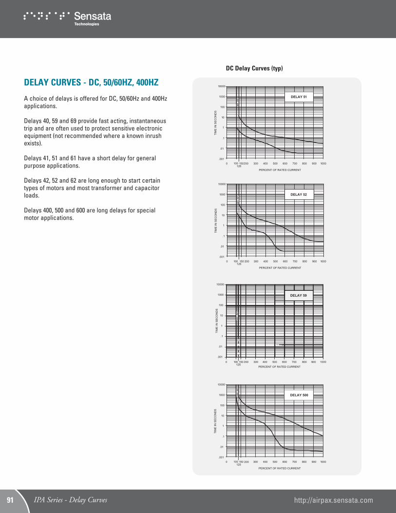
DC Delay Curves (typ)
DELAY CURVES - DC, 50/60HZ, 400HZ
A choice of delays is offered for DC, 50/60Hz and 400Hz applications. Delays 40, 59 and 69 provide fast acting, instantaneous trip and are often used to protect sensitive electronic equipment (not recommended where a known inrush exists). Delays 41, 51 and 61 have a short delay for general purpose applications. Delays 42, 52 and 62 are long enough to start certain types of motors and most transformer and capacitor loads. Delays 400, 500 and 600 are long delays for special motor applications.
IPA Series - Delay Curves http://airpax.sensata.com91
900 1000
PERCENT OF RATED CURRENT
.001
10000
.01
100
1000
.1
1
10
TIM
E I
N S
EC
ON
DS
0 100 200 300 400 500 600 700 800
MAY
TRI
P
900 1000
PERCENT OF RATED CURRENT
.001
10000
.01
100
1000
.1
1
10
TIM
E I
N S
EC
ON
DS
0 100150 200 300 400 500 600 700 800
MAY
TRI
P
900 1000
PERCENT OF RATED CURRENT
.001
10000
.01
100
1000
.1
1
10
TIM
E IN
SE
CO
ND
S
0 100 150 200 300 400 500 600 700 800
MAY
TRI
P
900 1000
PERCENT OF RATED CURRENT
.001
10000
.01
100
1000
.1
1
10
TIM
E IN
SE
CO
ND
S
0 100 150 200 300 400 500 600 700 800
MAY
TRI
P
DELAY 40
DELAY 41
DELAY 42
DELAY 400
1
900 1000
PERCENT OF RATED CURRENT
.001
10000
.01
100
1000
.1
10
TIM
E IN
SE
CO
ND
S
0 100125
150 200 300 400 500 600 700 800
MAY
TRI
P
DELAY 600
1
900 1000
PERCENT OF RATED CURRENT
.001
10000
.01
100
1000
.1
10
TIM
E IN
SE
CO
ND
S
0 100125
150 200 300 400 500 600 700 800
MAY
TRI
P
DELAY 61
900 1000800
DELAY 69
PERCENT OF RATED CURRENT
.001
10000
.01
100
1000
.1
1
10
TIM
E IN
SE
CO
ND
S
0 100125
150 200 300 400 500 600 700
MAY
TRI
P
1
900 1000
PERCENT OF RATED CURRENT
.001
10000
.01
100
1000
.1
10
TIM
E IN
SE
CO
ND
S
0 100125
150 200 300 400 500 600 700 800
MAY
TRI
P
DELAY 62
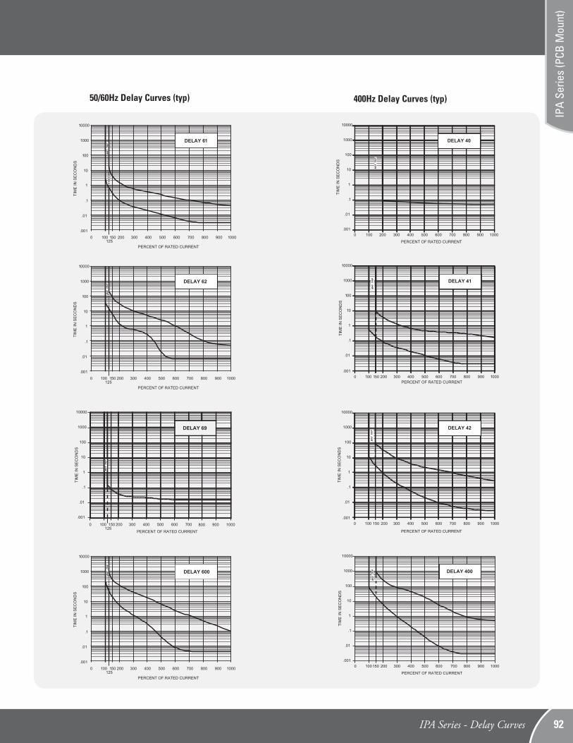
50/60Hz Delay Curves (typ) 400Hz Delay Curves (typ)
IPA Series - Delay Curves 92
IPA
Serie
s (P
CB M
ount
)
SPECIFICATIONS
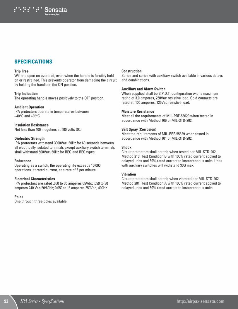
Trip FreeWill trip open on overload, even when the handle is forcibly held on or restrained. This prevents operator from damaging the circuit by holding the handle in the ON position.
Trip IndicationThe operating handle moves positively to the OFF position.
Ambient OperationIPA protectors operate in temperatures between–40°C and +85°C.
Insulation ResistanceNot less than 100 megohms at 500 volts DC.
Dielectric StrengthIPA protectors withstand 3000Vac, 60Hz for 60 seconds between all electrically isolated terminals except auxiliary switch terminals shall withstand 500Vac, 60Hz for REG and REC types.
EnduranceOperating as a switch, the operating life exceeds 10,000 operations, at rated current, at a rate of 6 per minute.
Electrical CharacteristicsIPA protectors are rated .050 to 30 amperes 65Vdc; .050 to 30 amperes 240 Vac 50/60Hz; 0.050 to 15 amperes 250Vac, 400Hz. PolesOne through three poles available.
ConstructionSeries and series with auxiliary switch available in various delays and combinations.
Auxiliary and Alarm SwitchWhen supplied shall be S.P.D.T. configuration with a maximum rating of 3.0 amperes, 250Vac resistive load. Gold contacts are rated at .100 amperes, 125Vac resistive load.
Moisture ResistanceMeet all the requirements of MIL-PRF-55629 when tested in accordance with Method 106 of MIL-STD-202.
Salt Spray (Corrosion)Meet the requirements of MIL-PRF-55629 when tested in accordance with Method 101 of MIL-STD-202.
ShockCircuit protectors shall not trip when tested per MIL-STD-202, Method 213, Test Condition B with 100% rated current applied to delayed units and 80% rated current to instantaneous units. Units with auxiliary switches will withstand 30G max.
VibrationCircuit protectors shall not trip when vibrated per MIL-STD-202, Method 201, Test Condition A with 100% rated current applied to delayed units and 80% rated current to instantaneous units.
IPA Series - Specifications http://airpax.sensata.com93
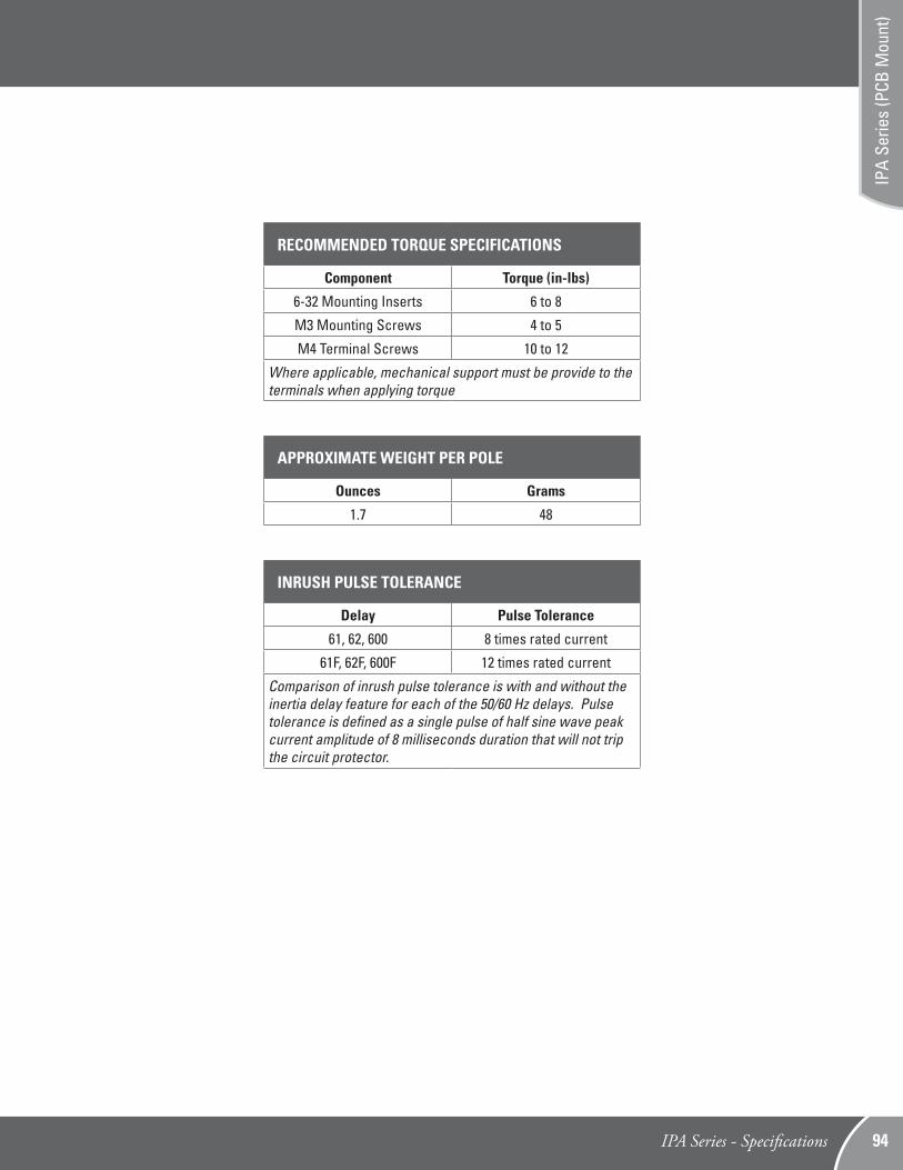
APPROXIMATE WEIGHT PER POLE
Ounces Grams
1.7 48
RECOMMENDED TORQUE SPECIFICATIONS
Component Torque (in-lbs)
6-32 Mounting Inserts 6 to 8
M3 Mounting Screws 4 to 5
M4 Terminal Screws 10 to 12
Where applicable, mechanical support must be provide to the terminals when applying torque
INRUSH PULSE TOLERANCE
Delay Pulse Tolerance
61, 62, 600 8 times rated current
61F, 62F, 600F 12 times rated current
Comparison of inrush pulse tolerance is with and without the inertia delay feature for each of the 50/60 Hz delays. Pulse tolerance is defined as a single pulse of half sine wave peak current amplitude of 8 milliseconds duration that will not trip the circuit protector.
IPA Series - Specifications 94
IPA
Serie
s (P
CB M
ount
)
Example:
1 32 4 85 6 7
IPAP -1 -1REC4 - 61- 10.0 - L - 01 - T
Eighth Decision (Optional)
TÜV*
CCC
8
Agency Approval
T
C
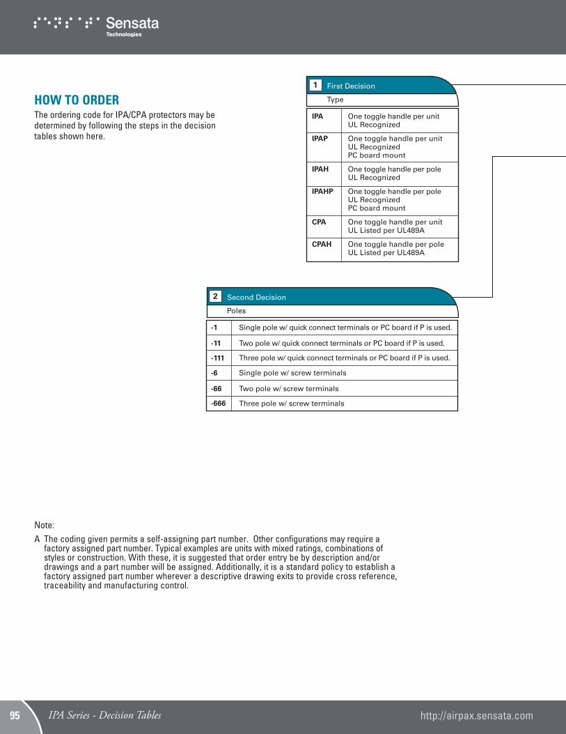
First Decision1
Type
One toggle handle per unitUL Recognized
One toggle handle per unitUL RecognizedPC board mount
One toggle handle per poleUL Recognized
One toggle handle per poleUL RecognizedPC board mount
One toggle handle per unitUL Listed per UL489A
One toggle handle per poleUL Listed per UL489A
IPA
IPAP
IPAH
IPAHP
CPA
CPAH
Third Decision3
Con�gurations
Notes: 1. For switch type, eliminate 4th & 5th decision. 2. Switch will be marked with Max. current & voltage. 3. The alarm switch is located in the handle pole for single handle types and in pole 2 for units with a handle per pole. The auxilliary switch may be located in any pole. However the standard location is in pole 2. 4. Switch type with alarm switch must be multi-pole connected to a pole equipped with either an overcurrent or overvoltage mechanism. (Consult factory for further information.)
-1
-1REC4
-1REG4
-1RS4
-1RSG4
Switch only
Series
Series with silver contactAuxiliary switch
Series with gold contactAuxiliary switch
Series with silver contactAlarm switch
Series with gold contactAlarm switch
Sixth Decision (Optional)6
Mounting & Terminal Type
Metric M3 mounting inserts and if screw terminals M4.
PC board mounting plate & terminals, 90 facing left
PC board mounting plate & terminals, 90 facing right
PC board terminals, rear facing with front panel insert mount.
Note: Right and Left determined with breaker viewed from the rear, in normal vertical mounted position. (see pages 70 & 71)
Notes: 1. *25 amperes max rated current for TÜV approval. 2. CCC Approval is pending.
A-
L-
R-
S-
Second Decision2
Poles
-1
-11
-111
-6
-66
-666
Single pole w/ quick connect terminals or PC board if P is used.
Two pole w/ quick connect terminals or PC board if P is used.
Three pole w/ quick connect terminals or PC board if P is used.
Single pole w/ screw terminals
Two pole w/ screw terminals
Three pole w/ screw terminals
Fourth Decision4
Frequency & Delay
Switch only
400Hz instant trip
400Hz short delay
400Hz long delay
400Hz motor start
DC instant trip*
DC short delay*
DC long delay*
DC motor start
50/60Hz instant trip
50/60Hz short delay
50/60Hz long delay
50/60Hz motor start
Note: For addition of inertial delay, add an “F” to any delay numeral. (Example: 62F) *CPA types are only available with DC ratings.
SW
-40
-41
-42
-400
-50
-51
-52
-500
-60
-61
-62
-600
Seventh Decision
Black with I/O markings
7
Handle Color
01
Fifth Decision5
Rated Current
Use three numbers to specify required value within ranges described below.
Rating
0.50 to 30.0*
Notes: 1. On multi-pole units, the poles are numbered left to right when viewed from terminal end. 2. *15 amps maximum at 400Hz
-0
HOW TO ORDERThe ordering code for IPA/CPA protectors may be determined by following the steps in the decision tables shown here.
Note:A The coding given permits a self-assigning part number. Other configurations may require a
factory assigned part number. Typical examples are units with mixed ratings, combinations of styles or construction. With these, it is suggested that order entry be by description and/or drawings and a part number will be assigned. Additionally, it is a standard policy to establish a factory assigned part number wherever a descriptive drawing exits to provide cross reference, traceability and manufacturing control.
IPA Series - Decision Tables http://airpax.sensata.com95
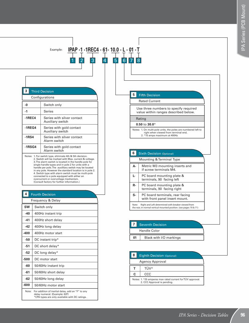
Example:
1 32 4 85 6 7
IPAP -1 -1REC4 - 61- 10.0 - L - 01 - T
Eighth Decision (Optional)
TÜV*
CCC
8
Agency Approval
T
C
First Decision1
Type
One toggle handle per unitUL Recognized
One toggle handle per unitUL RecognizedPC board mount
One toggle handle per poleUL Recognized
One toggle handle per poleUL RecognizedPC board mount
One toggle handle per unitUL Listed per UL489A
One toggle handle per poleUL Listed per UL489A
IPA
IPAP
IPAH
IPAHP
CPA
CPAH
Third Decision3
Con�gurations
Notes: 1. For switch type, eliminate 4th & 5th decision. 2. Switch will be marked with Max. current & voltage. 3. The alarm switch is located in the handle pole for single handle types and in pole 2 for units with a handle per pole. The auxilliary switch may be located in any pole. However the standard location is in pole 2. 4. Switch type with alarm switch must be multi-pole connected to a pole equipped with either an overcurrent or overvoltage mechanism. (Consult factory for further information.)
-1
-1REC4
-1REG4
-1RS4
-1RSG4
Switch only
Series
Series with silver contactAuxiliary switch
Series with gold contactAuxiliary switch
Series with silver contactAlarm switch
Series with gold contactAlarm switch
Sixth Decision (Optional)6
Mounting & Terminal Type
Metric M3 mounting inserts and if screw terminals M4.
PC board mounting plate & terminals, 90 facing left
PC board mounting plate & terminals, 90 facing right
PC board terminals, rear facing with front panel insert mount.
Note: Right and Left determined with breaker viewed from the rear, in normal vertical mounted position. (see pages 70 & 71)
Notes: 1. *25 amperes max rated current for TÜV approval. 2. CCC Approval is pending.
A-
L-
R-
S-
Second Decision2
Poles
-1
-11
-111
-6
-66
-666
Single pole w/ quick connect terminals or PC board if P is used.
Two pole w/ quick connect terminals or PC board if P is used.
Three pole w/ quick connect terminals or PC board if P is used.
Single pole w/ screw terminals
Two pole w/ screw terminals
Three pole w/ screw terminals
Fourth Decision4
Frequency & Delay
Switch only
400Hz instant trip
400Hz short delay
400Hz long delay
400Hz motor start
DC instant trip*
DC short delay*
DC long delay*
DC motor start
50/60Hz instant trip
50/60Hz short delay
50/60Hz long delay
50/60Hz motor start
Note: For addition of inertial delay, add an “F” to any delay numeral. (Example: 62F) *CPA types are only available with DC ratings.
SW
-40
-41
-42
-400
-50
-51
-52
-500
-60
-61
-62
-600
Seventh Decision
Black with I/O markings
7
Handle Color
01
Fifth Decision5
Rated Current
Use three numbers to specify required value within ranges described below.
Rating
0.50 to 30.0*
Notes: 1. On multi-pole units, the poles are numbered left to right when viewed from terminal end. 2. *15 amps maximum at 400Hz
-0
IPA Series - Decision Tables 96
IPA
Serie
s (P
CB M
ount
)