Embed Size (px)
Citation preview

PAPERS
0 INTRODUCTION
The basic topology of a single-coil drive for a modernloudspeaker, with the magnet placed inside the voice coil,can be seen in Fig. 1. Here the notation shows the direc-tion of the magnetic flux, current, and force as prescribedby Lorentz. The notion of creating a dual-coil drive is rel-atively straightforward and is illustrated in Fig. 2. Imaginethat the single coil in Fig. 1 is simply a two-layer coil,which is then separated into two coils and placed in theconfiguration seen in Fig. 2. In this figure the return cir-cuit for the flux has been severed and a second air gap isformed. The second coil is then placed in this gap, posi-tioned in the same axis as the first coil, and wound on thesame voice-coil former. Because the flux in the return por-tion of the circuit is in the opposite direction to that in theupper gap, the second coil will need to have current flow-ing in the direction opposite to the first in order for theLorentz force placed on both coils to be in the same direc-tion. The notations in Fig. 2 show this clearly.
To begin comparing the single-coil design with the dual-coil-drive design certain constraints are needed to make anapples-to-apples comparison. As we shall see later, thedual-coil drive has more design flexibility, resulting in amuch greater number of possible configurations. For thisinitial discussion we will constrain the coil mass to be thesame in both designs. As mentioned, imagine simply cut-
J. Audio Eng. Soc., Vol. 50, No. 6, 2002 June 427
Magnetic Circuit Design Methodologies forDual-Coil Transducers*
DOUGLAS J. BUTTON, AES Fellow
JBL Professional, Northridge, CA 91329, USA
Although the electrodynamic drive topology incorporating two axially (not concentrically)placed coils is not a new idea and dates back to the 1950s, recent interest in the design hasstarted a proliferation of the design conception professional and consumer markets. Thefundamental design involves two coils that are opposite in phase and reside in oppositelypolarized magnetic gaps, thus providing a Lorentz force in the same axial direction. The twogaps are formed from the same magnetic circuit, and both coils are wound on the same form,separated by some distance, connected or wound out of phase, and attached to a singlediaphragm. Different design options with magnetic materials, magnetic circuit geometries,and voice-coil topologies are described. The focus is on performance tradeoffs and advan-tages in weight, power handling, power compression, and distortion relative to a single-gapdesign.
*Presented at the 103rd Convention of the Audio EngineeringSociety, New York, NY, 1997 September 26–29; revised 2002February 6. Fig. 2. Dual-coil-drive motor, one-half cross section.
Fig. 1. Standard single-gap motor, one-half cross section.
MagnetMagnet
SteelSteel
SteelSteel
SteelSteel
NN
SS
ForceForce
CurrentCurrentFluxFlux
Coil 2Coil 2
Coil 1Coil 1
Cent
erlin
eCe
nter
line
SteelSteelMagnetMagnet
NN
SS
SteelSteel
SteelSteelFluxFlux
Coil 1Coil 1
ForceForce
ForceForce
FluxFlux
Coil 2Coil 2
Cent
erlin
eCe
nter
line

BUTTON PAPERS
ting the single coil lengthwise in half and placing eachhalf in the two gaps. The two gaps will now be tighter thanthe single one. In fact, they will be close to one-half thewidth of the single gap. In doing this, the reluctance of thesingle gap will be very nearly the same as that of the twogaps in the dual-coil drive. If this is the case, we shouldexpect the flux densities B of the two gaps to be very nearlyidentical to the single gap. Also if we imagine the singlecoil to be a two-layer coil with the coils in series, then sep-arating them while keeping them connected in series, thedc resistance (DCR) will be the same, as will be the totallength l of the coils. We now have a comparison where thecoil overhang, mass, DCR, and Bl product are the same inboth cases. Therefore the small-signal Thiele–Small (TS)[1], [2] parameters and the efficiencies of the two designsare the same. The clear improvement in the dual-coil-drivedesign, however, is that the surface area of the coil has nowdoubled. As prescribed by Henricksen [3],
RAK
L� (1)
where
R � thermal resistance, °C/WL � length of thermal path, mA � area of thermal path, m2
K � thermal conductivity, °C • m/W.
We can see that doubling A will lead to a thermal resist-ance value for the dual-coil-drive design that is half thatfor the single-coil design. According to Button [4], [5] this
will lead to either a doubling of the power handing or ahalving of the power compression and, ultimately, an in-crease in the maximum output capability of the driver by3 dB. While other configurations keeping the surface areaconstant might yield different results in TS parameters andefficiencies, this simple clear comparison shows that thedual-coil drive can have twice the maximum power outputcapability of the single-coil design.
1 HISTORY
As early as the 1950s patents began to surface describ-ing a loudspeaker transducer with two voice coils spacedapart axially, which were wound in opposite directions onthe same voice-coil former and connected in series (Figs. 3[6] and 4 [7]). The coils were separated by several mil-limeters. The magnetic circuits were based on an alnicopermanent magnet and showed two magnetic air gaps ateither end of the magnet, with one coil placed in each gap.This clever topology allowed the magnetic flux from themagnet to be used twice with a claimed increase in theLorentz force generated by the driver. Although the authorsmay not have directly considered it, the two coils withtwice the surface area of a single-coil design would handletwice the input power. The design appears to have beenahead of its time since drivers in the 1950s did not need tohandle high power. Consequently the design never foundcommercial success, and no popular designs of the time canbe found using this methodology. As can be seen in bothFigs. 3 and 4, the inventors also predicted the need for usingsuspension elements at both ends of the dual-coil drive.
In Fig. 5 Surh [8] shows an interesting twist on thedesign without a return circuit collar, incorporating twocompletely separate magnet assemblies. This designwould certainly suffer with poor heat dissipation fromthe two coils, without the steel on the outside diameter ofthe coils to transfer heat, but is it innovative in that itwould be lighter in weight. The unique attachment at
428 J. Audio Eng. Soc., Vol. 50, No. 6, 2002 June
Fig. 4. Early dual-coil drive. (From Kritter [7], 1959.) 1––mag-net; 2––steel pole piece; 3, 4––steel plates. Fig. 5. Unusual dual-coil drive. (From Surh [8], 1965.)
Fig. 3. Early dual-coil drive. (From Wolff [6], 1954.)CM––magnet; A1, A2––air gaps; C1, C2––coils; P1, P2––steel plates; PP2––pole piece.

PAPERS DESIGN METHODOLOGIES FOR DUAL-COIL TRANSDUCERS
each of the dual coils would also provide a very robustdrive mechanism.
In recent years the author has been deeply involved withtrying to improve the output capabilities of professionaltransducers. Also, in the past few years weight reductionhas become extremely important. In 1990, completelyunaware of the 1950s work, the author reinvented themethodology with neodymium as the magnetic material.The dual-coil-drive motor built in 1994 and patented in1998 [9] is shown in Fig. 6. The use of neodymium furtherimproved the methodology to include a vast weight reduc-tion and a more compact topology as additional benefits.The motor for the unit pictured in Fig. 6 weighs only 1.5lb (0.68 kg) and has an AES (1984) power-handling capa-bility of 250 W. The 15-in (381-mm) driver on which it isused has a very high efficiency of nearly 100 dB for 1 Wof input power measured at 1 m. A single-coil ceramicmagnet based driver with this type of performance couldeasily have a motor structure that weighs 10 times as muchas the one in this design. However, because this design isso small, it is necessary to heat sink the small structure inorder to dissipate the heat that is generated by the twocoils. The design illustrated in Fig. 6 is innovative in thatit shows an elegant heat sinking method. The configura-tion is well suited for immersion in a substantial alu-minum structure with generous ribbing. This compactarrangement not only allows the heat sink design to betruly effective, but it sets the stage for the heat sink to then
work as part of the loudspeaker structure as a whole, andit is very light in weight.
Over the course of the last decade the methodology hasbegun to gain wider acceptance and usage. In Fig. 7 Nokia[10] presents a design not unlike Krittner’s [7], but itshows an improvement in the magnetic circuit––under-cuts in the pole––which would help focus the field in thegaps. This design also provides a generous suspension onboth ends of the coil. Paddock [11] shows a further inno-vation by revealing a unique manner of fabricating the twocoils out of a single rectangle of traces etched on aprinted-circuit board (Fig. 8). The board is then rolled intoa cylinder, creating a dual coil that is prewired with thecorrect reversal of current.
Tanabe and Shimamura [12] reveal a very interestinginnovation in the use of an injection-moldable magnet fora large part of the magnetic circuit (Fig. 9). The materialis a plastic binder with neodymium magnet particles sus-pended in it. While this material does not have the energydensity of a solid neodymium iron boron magnet, accord-
J. Audio Eng. Soc., Vol. 50, No. 6, 2002 June 429
Fig. 7. Refined magnetic circuit. (From Nokia [10], 1992.)
Fig. 6. Modern dual-coil drive made with neodymium magnetand nested in a heat sink, 1994. (From Button [9], 1998.)
Fig. 9. Lightweight plastic magnet dual-coil drive. (From Tanabeand Shimamura [12], 1996.)
Fig. 8. Innovative coil fabrication technique. (From Paddock[11], 1995.)

BUTTON PAPERS
ing to Button’s 1994 design, this structure would certainlybe cost effective and lightweight. However, the plasticwould be poor at heat transfer and in high-temperatureoperation. This design would not be robust in a high-performance application, but it would certainly have wideacceptance where weight alone was the most importantfactor.
Hirozawa [13] shows in Figs. 10 and 11 an additionaltwist to dual-coil-drive design by using one of the dualgaps to drive a second concentric set of coils for a high-frequency coaxial unit. The creation of two sets of dualgaps from the same magnet is shown in Fig. 12.
The value of the dual-coil-drive methodology is not just
limited to loudspeakers. Godkin et al. [14] show in Fig. 13the use of a double dual-coil-drive configuration in a lin-ear actuator. What is again claimed is an ability to effi-ciently create greater maximum output force.
Circuits using neodymium, ceramic, and even plasticmagnetic materials are all available in the commercialmarketplace. There are a variety of parameters––weight,power handling, power compression, motor force, low-frequency linearity, flux modulation, and cost––that canbe juggled to suit the intended application. The dual-coil-drive approach can be superior to a single-coil approach,depending on how one chooses to weight the value of thedifferent measures of performance.
2 MAGNETIC ANALYSIS
In order to support the claims made in the Introduction,namely, that a dual-coil drive provides greater perform-ance, a more detailed analysis is required. First let usexamine the magnetic circuit of the dual-coil drive illus-trated in Fig. 2 and compare it to the single-coil design ofFig. 1. Fig. 14 represents the flux lines in the single-coildesign as calculated by a finite-element-analysis (FEA)computer program. The magnet is inside the coil diameter,and the coil represented is 3.0 in (76.2 mm) in diameterand 0.8 in (20.3 mm) long, with a winding width of 0.1 in(2.5 mm). It is assumed that the coil is an edge-woundcoil, but round-wire dual coils should behave identically,except that the number turns for a given coil cross section
430 J. Audio Eng. Soc., Vol. 50, No. 6, 2002 June
Fig. 12. Two dual-coil drives in single structure. (From Hirozawa[13], 1994.)
Fig. 11. Dual-coil drive with high-frequency drive. (From Hiro-zawa [13], 1994.)
Fig. 10. Dual-coil drive with high-frequency drive. (From Hiro-zawa [13], 1994.)
Fig. 13. Linear actuator. (From Godkin et al. [14], 1989.)
Fig. 14. Flux plot for single-gap-motor design of Fig. 1.
PAPERS DESIGN METHODOLOGIES FOR DUAL-COIL TRANSDUCERS
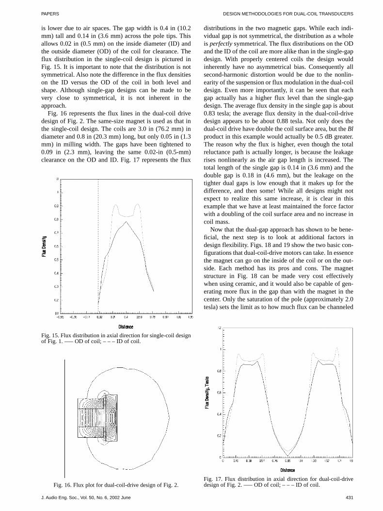
is lower due to air spaces. The gap width is 0.4 in (10.2mm) tall and 0.14 in (3.6 mm) across the pole tips. Thisallows 0.02 in (0.5 mm) on the inside diameter (ID) andthe outside diameter (OD) of the coil for clearance. Theflux distribution in the single-coil design is pictured inFig. 15. It is important to note that the distribution is notsymmetrical. Also note the difference in the flux densitieson the ID versus the OD of the coil in both level andshape. Although single-gap designs can be made to bevery close to symmetrical, it is not inherent in theapproach.
Fig. 16 represents the flux lines in the dual-coil drivedesign of Fig. 2. The same-size magnet is used as that inthe single-coil design. The coils are 3.0 in (76.2 mm) indiameter and 0.8 in (20.3 mm) long, but only 0.05 in (1.3mm) in milling width. The gaps have been tightened to0.09 in (2.3 mm), leaving the same 0.02-in (0.5-mm)clearance on the OD and ID. Fig. 17 represents the flux
distributions in the two magnetic gaps. While each indi-vidual gap is not symmetrical, the distribution as a wholeis perfectly symmetrical. The flux distributions on the ODand the ID of the coil are more alike than in the single-gapdesign. With properly centered coils the design wouldinherently have no asymmetrical bias. Consequently allsecond-harmonic distortion would be due to the nonlin-earity of the suspension or flux modulation in the dual-coildesign. Even more importantly, it can be seen that eachgap actually has a higher flux level than the single-gapdesign. The average flux density in the single gap is about0.83 tesla; the average flux density in the dual-coil-drivedesign appears to be about 0.88 tesla. Not only does thedual-coil drive have double the coil surface area, but the Blproduct in this example would actually be 0.5 dB greater.The reason why the flux is higher, even though the totalreluctance path is actually longer, is because the leakagerises nonlinearly as the air gap length is increased. Thetotal length of the single gap is 0.14 in (3.6 mm) and thedouble gap is 0.18 in (4.6 mm), but the leakage on thetighter dual gaps is low enough that it makes up for thedifference, and then some! While all designs might notexpect to realize this same increase, it is clear in thisexample that we have at least maintained the force factorwith a doubling of the coil surface area and no increase incoil mass.
Now that the dual-gap approach has shown to be bene-ficial, the next step is to look at additional factors indesign flexibility. Figs. 18 and 19 show the two basic con-figurations that dual-coil-drive motors can take. In essencethe magnet can go on the inside of the coil or on the out-side. Each method has its pros and cons. The magnetstructure in Fig. 18 can be made very cost effectivelywhen using ceramic, and it would also be capable of gen-erating more flux in the gap than with the magnet in thecenter. Only the saturation of the pole (approximately 2.0tesla) sets the limit as to how much flux can be channeled
J. Audio Eng. Soc., Vol. 50, No. 6, 2002 June 431
Fig. 15. Flux distribution in axial direction for single-coil designof Fig. 1. ––– OD of coil; – – – ID of coil.
Fig. 16. Flux plot for dual-coil-drive design of Fig. 2.Fig. 17. Flux distribution in axial direction for dual-coil-drivedesign of Fig. 2. ––– OD of coil; – – – ID of coil.

BUTTON PAPERS
through the circuit. This solution, however, would tend tobe heavier and would have much more leakage flux fromthe OD of the magnet. For lower weight and better mag-netic efficiency (lower leakage) the method shown in Fig.
19, using either neodymium or alnico, would prove morevaluable. Neodymium would be the lightest, but alnico hasa higher magnetic bias, and more total flux lines could begenerated in the circuit, at the expense of it becoming verytall and heavy. If maximum performance and minimumweight are the important design factors, the configurationin Figs. 2 and 19 with neodymium would provide the opti-mum solution.
3 LINEARITY
The next step in confirming the value of the dual-coildrive is to examine the maximum linear excursion xmax ofeach approach. Fig. 20 compares the flux lines passingthrough (linked to) the coil in the single-coil design of Fig.1 to the axial position of the coil as measured on a proto-type motor. Fig. 21 compares the actual motor strengthRME of the coil to the axial position as calculated by
[ ]RB l
DCRmechanical ohms� �ME
2 2
where
B � average flux density in coil, teslal � length of wire in coil, mDCR � dc resistance of coil, W.
In each case two different coil lengths are displayed.Interestingly, the longer coil [0.8 in (20.3 mm)] has ahigher motor strength than the shorter one [0.5 in (12.7mm)]. The gap is 0.4 in (10.2 mm) tall. Normally onewould expect the shorter coil to have a higher motorstrength because the average flux density throughout thecoil is typically so much higher. However, because theleakage is so high, the longer coil is able to utilize theleakage and realize a higher motor strength.
432 J. Audio Eng. Soc., Vol. 50, No. 6, 2002 June
Fig. 18. Dual-coil-drive configuration with magnet on outside ofcoils.
Fig. 20. Flux lines linked to coil versus coil position in single-gap design for two different coil lengths. Top curve––0.8-in (20.3-mm)-long coil; bottom curve––0.5-in (12.7-mm)-long coil.
Fig. 19. Dual-coil-drive configuration with magnet on inside ofcoils.
-200000
-100000
0
100000
200000
300000
400000
500000
600000
-1.5 -1 -0.5 0 0.5 1 1.5
Coil Position, positive is toward front of speaker
Flu
x lin
es li
nke
d t
o c
oil,
Max
wel
l tu
rns

PAPERS DESIGN METHODOLOGIES FOR DUAL-COIL TRANSDUCERS
The length of the coil is the only variable one has toadjust the linearity in a single-gap design. However, in thedual-coil drive there is an additional parameter to adjustthe linearity versus RME tradeoff, namely, the spacingbetween the coils in addition to the length of the coils. Fig.22 shows five possible spacings for a 0.5-in (12.7-mm)long pair of coils. This additional flexibility calls for a bitof nomenclature for the specific configurations. For thisreason we adopted the terms “positive and negative inner-hang” and “positive and negative outerhang.” To visualizethis, only think of the upper coil. In all dual-coil designsthe coil placement is symmetrical with respect to the mag-netic structure. Innerhang is defined as the distance fromthe inside edge of the top plate to the inside end of the coil.Positive innerhang means the coil hangs below the bottomof the top plate. Negative innerhang then represents a coilwhose lower end is actually above the bottom of the plateand in the magnetic gap. Outerhang is simpler. Positiveouterhang is the same as the traditional term, overhang (theamount above or outside the top plate). Negative outerhangis similar to the traditional underhung (in which the top ofthe coil is below the top of the top plate in the magneticgap), but it only applies to the part of the coil toward theouter part of the structure. These conventions make it eas-ier to understand the legends in the following figures. Fig.23 shows the flux lines through the coils in each case.Note the number of lines is about double that in the single-
coil design as the lines are used twice. Fig. 24 gives thecalculated RME of each of the possible configurations.These figures represent magnetic flux data taken on anactual dual-coil-drive motor like that in Fig. 2. From theseplots we can make direct comparisons with the single-coildesign. In addition Figs. 25, 26, and 27 show the sametype of data for a 0.8-in (20.3-mm)-long coil).
There is a huge array of possibilities relative to thesingle-coil design. Button [15] suggests that the xmax of amotor design is the displacement where the Bl product hasbeen reduced to 65% of its value in the static position.Recent work by the author suggests that the point whereRME reaches 50% may be a better number and is a simplerrule of thumb. For the sake of comparison Table 1 lists thexmax values as prescribed by the displacement, where RMEis half the maximum value.
The coil is 3.0 in (76.2 mm) in diameter, the magnet is0.7 in (17.8 mm) thick, and the plates are 0.4 in (10.2 mm)thick. It is clear that the dual-coil design has just as muchlinearity for the same RME and has the capability of havinga much higher RME with only slightly less linearity. Also,you can have extremely high xmax at the sacrifice of RMEbut not at the expense of coil mass. Probably twice the coilmass would be required in the single-coil design to makethe coil long enough to achieve the very high 0.65� xmaxfigure (see Table 1). In the dual-coil-drive design theshorter coil does in fact have a higher RME than the longer
J. Audio Eng. Soc., Vol. 50, No. 6, 2002 June 433
Fig. 21. Motor strength RME versus coil position in single-gap design for two different coil lengths. Top curve––0.8-in (20.3-mm)-longcoil; bottom curve––0.5-in (12.7-mm)-long coil.
0
20
40
60
80
100
120
140
160
-1.5 -1 -0.5 0 0.5 1 1.5
Coil position
Mo
tor
stre
ng
th,
Rm
e
Fig. 22. Coil configurations for 0.5-in (12.7-mm)-long coils in Figs. 23 and 24
Coil 1 Coil 2 Coil 3 Coil 4 Coil 5

BUTTON PAPERS
coil because the leakage is low. A driver with a short, lightcoil and very high RME, as might be required for a horn ora midrange driver, would find superior performance in thedual-coil-drive configuration.
The dual-coil-drive approach is equal or superior to the
single-coil design in both linearity and efficiency, and itstill has double the coil surface area.
The use of neodymium has additional benefits in lin-earity due to lower flux modulation over ceramic magnets.Fig. 28 from Button [16] shows the change in the flux dis-
434 J. Audio Eng. Soc., Vol. 50, No. 6, 2002 June
Fig. 23. Flux lines linked to 0.5-in (12.7-mm)-long coils versus position in dual-coil-drive design for five different coil spacings.
Fig. 25. Coil configurations for 0.8-in (20.3-mm)-long coils in Figs. 26 and 27.
Coil1 Coil 2 Coil 3 Coil 4 Coil 5
Fig. 24. Motor strength RME versus position in dual-coil-drive design for five different coil spacings of 0.5-in (12.7-mm)-long coils.

PAPERS DESIGN METHODOLOGIES FOR DUAL-COIL TRANSDUCERS
J. Audio Eng. Soc., Vol. 50, No. 6, 2002 June 435
Fig. 27. Motor strength RME versus position in dual-coil-drive design for five different coil spacings of 0.8-in (20.3-mm)-long coils.
Fig. 26. Flux lines linked to 0.8-in (20.3-mm)-long coils versus position in dual-coil-drive design for five different coil spacings.
Table 1. xmax and RME for single- and dual-coil designs of twocoil lengths.*
Space 0.8-in (20.3-mm) Coil 0.5-in (12.7-mm) Coil
[in (mm)] xmax (RME) xmax (RME)
Single-gap design
0.33 129 0.25 114
Dual-coil-drive design
0.3 (7.6) 0.31 153 –– ––0.5 (12.7) 0.32 151 0.27 1590.7 (17.8) 0.34 127 0.27 1600.9 (22.9) 0.44 84 0.27 1141.1 (27.9) 0.65� 50 0.40 701.3 (33) –– –– 0.60 34
*Data taken from Figs. 20–27.

BUTTON PAPERS
tribution across a voice-coil gap in time steps over thecourse of a sine wave. This nonlinear change in flux cre-ates a back EMF in the coil that has harmonic compo-nents. This phenomenon is known as flux modulation andresults in harmonic distortion in the midband frequenciesof a driver. Fig. 29, taken from [17], shows that the totalchange or modulation of the B field relative to the operat-ing point is considerably more dramatic in ceramic than inneodymium. As pictured, the modulation consumes nearlyone-third of the load line in ceramic whereas in neo-dymium it is only about one-tenth. This difference trans-lates into 10 dB less distortion due to flux modulation in aneodymium-based motor.
4 HEAT DISSIPATION
Throughout this paper the contention has been thatdoubling the surface area of the coil will result in 3 dBmore maximum output, and we have suggested that quitepossibly the dual-coil drive will have a little more effi-ciency for the same coil overhang. Fig. 30 compares thepower compression of two 10-in (254-mm)-diameterdrivers. One is a traditional single-gap model, the 2123.The second is a similar driver equipped with a dual-coil-drive motor, the 2251 (Fig. 31). The comparison shows amuch more linear relationship between input power andsound pressure output as the power is increased. The2251 has half the power compression of the 2123. Thiscomparison is very valid as the coil in the 2123 is of thesame height as one of the coils in the 2251 [a little lessthan 0.5 in (12.7 mm)]. The dual coils live up to theexpectation that the heat dissipation is twice as effectivewith two coils as with one. Fig. 32 shows the sound pres-sure levels versus time for the two drivers when poweredwith full-power pink noise. A decade of 300 to 3000 Hzpink noise is used. These drivers are midrange, designedfor use in this range. Clearly, the 2251 (400-W rating)outperforms the 2123 (200 W) by more than 3 dB, evenafter power compression has set in. Both drivers powercompress the same amount at full power, suggesting thatthe voice coils are operating at the same temperature andthat the ratings are appropriate. The dual-coil drive is ableto dissipate twice the power and stay at the same temper-ature. The contention that the dual-coil drive will supplyat least 3 dB more maximum output has been proven. Aswith the structure from Fig. 6, the 2251 motor is wellsuited for encasement in a generous heat sink. This heatsink is truly effective with large fins, and if made fromaluminum it would still be very light. Fig. 33 shows the2251 in a unique configuration, where the substantial heatsink is external to the enclosure and additional cooling tothe heat sink can be realized by virtue of a channel inwhich the motor rests, resulting in a chimney coolingeffect. Furthermore, the motor for the 2251 weighs only2.5 lb (1.13 kg). This compares with 15 lb (6.8 kg) for the2123 motor and well over 20 lb (9 kg) for some compet-itive high-performance drivers on the market today.Interestingly, because there is such a reduction in theamount of steel required, the neodymium design is verycost competitive with a ceramic single-gap design using
large amounts of steel, despite the higher cost of theneodymium magnet.
5 INDUCTANCE REDUCTION
An additional benefit of the dual-coil-drive configura-tion is that it exhibits much lower inductance than a coilwith the same total number of turns in one gap. Any twocoils that are in close proximity to each other share aninductive component called mutual inductance. If twocoils are wound on top of each other, they have a very highcomponent of mutual inductance. As the coils are sepa-rated, the mutual inductance component decreases. This
436 J. Audio Eng. Soc., Vol. 50, No. 6, 2002 June
Fig. 28. Flux modulation in voice-coil gap. (From Button [16],1991.)
Fig. 29. Second-quadrant load line flux modulation of neo-dymium and ceramic magnets. (From [17], 1997.)

PAPERS DESIGN METHODOLOGIES FOR DUAL-COIL TRANSDUCERS
alone would cause the dual-coil design to have lowerinductance than the single-coil design. But even moreinteresting, because the coils are wired in reverse polar-ity, the mutual inductive component is in fact negative.Fig. 34 shows an impedance curve of a dual-coil drive inan unmagnetized pot structure with the coils’ wire in
phase and in reverse phase. The impedance curve of theexample with the coils in reverse polarity shows a lowertotal inductance, and it shows the corner frequency risinga full octave from 200 to 400 Hz. This is no doubtextremely beneficial in a driver intended for use in amidrange loudspeaker.
J. Audio Eng. Soc., Vol. 50, No. 6, 2002 June 437
100
105
110
115
120
1 10 100
Input power, Watts.
So
un
d p
ress
ure
leve
l @ 1
m
2251(Dual)
2123(single)
Ideal
Fig. 30. Comparison of power compression for single-gap (2123) and dual-coil-drive (2251) transducers.
Fig. 31. Cross section of 10-in (254-mm) midrange transducer (2251).
105
110
115
120
125
0 10 20 30 40 50 60
Seconds
So
un
d p
ress
ure
at
1 m
eter
(h
alf
spac
e), d
B
Fig. 32. Comparison of maximum output for single-gap (2123) and dual-coil-drive (2251) transducers. ––– 2251; – – – 2123.

BUTTON PAPERS
6 DESIGN IMPROVEMENTS
The Achilles heel of the dual-coil-drive configurationcomes when the design is examined for high-excursionapplications. Most of the designs on the market are nothigh-excursion designs. The problem is, what happenswhen one coil leaves the gap and moves into the otherone? Figs. 24 and 27 both show the motor force going tozero at about 0.75 in (19 mm) in that design. Beyond thatthe motor force comes back up and would reverse inphase. This would be useful as a braking action exceptthat, as first described by Barlow [18], in the frequencyregion near the high motional impedance, due to the backEMF at resonance, the coil wants to seek a position oflower RME. If there is any asymmetry, the coil will jumpout of the gap in that direction in any normal loudspeaker.
Also even if everything is balanced, and the programmaterial has an asymmetrical waveform in this frequencyrange, it will pop out the coil anyway. This dynamic offsetphenomenon is well witnessed by many loudspeaker engi-neers. It is typically counteracted by using a progressivesuspension having a stiffness versus deflection curve thatmirrors the inverse of the loss of RME versus displacementof the coil [18]. The only down side of this method is thatwhen the suspension is operating in a nonlinear region, itis much more prone to fatigue. In the case of a dual-coil-drive driver the jump out is even more dramatic at theextremes of travel. Because not only is RME decreasing, itwill go negative and further increase the jump-out force.Spacing coils very far apart works quite well. However,the suspension is still required to have sufficient progres-sive stiffness, as in a normal design.
In an attempt to solve this problem in a single-coildesign Wiik [19] patented the dynamic brake shown inFig. 35. The design involves two shorted coils at either endof the driving coil. At each extreme of the voice coil’stravel the shorted coil enters the gap and creates a backEMF proportional to the velocity of the coil. A current isthen generated in the shorted coil, which creates a Lorentzforce opposite to the direction of velocity, slowing downthe coil. Hence the term, dynamic brake. A further refine-ment of this idea was proposed by Nokia [10] and is
438 J. Audio Eng. Soc., Vol. 50, No. 6, 2002 June
Fig. 34. Inductance reduction due to negative mutual inductance of coils wired in reverse.
Fig. 35. Dynamic brake design. (From Wiik [19], 1979.) 12,13––shorted braking coils; 11––drive coil.Fig. 33. Upper transducer (2251) in chimney enclosure.

PAPERS DESIGN METHODOLOGIES FOR DUAL-COIL TRANSDUCERS
shown in Fig. 36. In the Nokia design the coils are notshorted but driven externally by an amplifier that injects acurrent in coils placed at the ends of the drive coil when itstarts to enter the gap. Presumably there is some form ofmotion sensing to tell the braking amplifier when to dothis. A refinement of the dual-coil-drive design to accom-plish what Wiik [19] had presented is shown in Fig. 37.This configuration is elegant in that only one braking coilis required instead of the two in the Wiik design [19]. Thiswill reduce the mass of the braking coil by 50%. Figs. 38and 39 show the positions of the braking coil as it starts totake effect in each direction, and Fig. 40 presents the effectof the braking shorted coil on the voltage required to reacha certain excursion in a 10-in (254-mm) driver. The coilarrangement is very similar in Figs. 37–39, that is, 0.6 in(15.2 mm) of excursion (in one direction) represents thepoint at which the braking coil is totally immersed in thegap. Shown is the effect with and without the coil shorted.Clearly, with the braking coil shorted, a higher voltage canbe put on the driver without overexcursion. The braking isgradual and could be thought of as a soft clipping, sug-gesting that the audible side effects would be minimal. Thegreat advantage of this approach is that excursion limitingor progressive velocity reduction is converted into heat, notwear and tear on the suspension. Fig. 41 shows a cross sec-tion of a dual-coil driver designed for a studio monitoringapplication with two stationary shorting rings to reduceinductance and distortion, and with a braking coil forexcursion protection, placed on the moving assembly.
7 CONCLUSIONS
The dual-coil-drive approach to loudspeaker motordesign actually has a long history. The methodology pro-vides additional flexibility in design choices and clearlydelivers an increase of more than 3 dB in maximum out-put over a single-gap design. Also, when realized usingneodymium as a magnet material and with proper nest-ing of the structure in a well-designed heat sink, thedesign can yield a significant reduction in weight, lowerdistortion, lower power compression, and lower induc-tance than a traditional single-gap design and yet main-tain cost competitiveness. The addition of a third,shorted coil between the two drive coils, acting as adynamic brake, can furthermore improve performance athigh excursions.
8 ACKNOWLEDGMENT
The author would like to thank Ralph Hyde for thedetailed measurements and flux plots of the magnetic cir-cuits presented herein, and David Blore for working outall of the engineering details in the design of the 2251.Thanks also go to Mark Gander and Bill Gelow for men-toring, guiding, cajoling, and prodding.
J. Audio Eng. Soc., Vol. 50, No. 6, 2002 June 439
Fig. 37. Dynamic braking design in dual-coil-drive motor.
Fig. 39. Braking effect in lower gap. As coil moves backward,braking takes place from the same shorted coil as it enters thelower gap.
Fig. 36. Active dynamic brake design. (From Nokia [10], 1992.)23, 24––actively driven coils with reverse current to slow coilvelocity when coil is overdriven.
Fig. 38. Braking effect in upper gap. As coil moves forward, itwill slow as the shorted turn enters the gap.

BUTTON PAPERS
9 REFERENCES
[1] A. N. Thiele, “Loudspeakers in Vented Boxes,” PartsI and II, Proc. IRE (Australia), vol. 22, pp. 487–508 (1961Aug.); reprinted in J. Audio Eng. Soc., vol. 19, pp.382–392 (1971 May); ibid., pp. 471–483 (1971 June).
[2] R. H. Small, “Direct-Radiator Loudspeaker SystemAnalysis,” IEEE Trans. Audio Electroacoust., vol. AU-19,pp. 269–281 (1971 Dec.); reprinted in J. Audio Eng. Soc.,vol. 20, pp. 383–395 (1972 June).
[3] C. A. Henricksen, “Heat-Transfer Mechanisms inLoudspeakers: Analysis, Measurement, and Design,” J.Audio Eng. Soc., vol. 35, pp. 778–791 (1987 Oct.).
[4] D. J. Button, “Heat Dissipation and Power Com-pression in Loudspeakers,” J. Audio Eng. Soc., vol. 40, pp.32–41 (1992 Jan./Feb.).
[5] D. J. Button, “Maximum SPL from Direct Rad-iators,” presented at the 97th Convention of the Audio
Engineering Society, J. Audio Eng. (Abstracts), vol. 42, p.1062 (1994 Dec.), preprint 3934.
[6] J. Wolff, “Improvements in Telephone Instrumentsand Microphones of the Moving Coil Type,” British patent705,100 (1954 Mar. 10).
[7] L. Kritter, “Electrodynamic Loudspeaker,” Frenchpatent 1,180,456 (1958 Dec. 29); published 1959 June 4.
[8] P. C. Surh, “Dynamic Speaker,” US patent3,201,529 (1965 Aug. 17).
[9] D. J. Button, “Dual Coil Drive with MultipurposeHousing,” US patent 5,748,760, assignees Harman Inter-national (1998 May 5).
[10] Nokia (Deutschland) GmbH, “Drive System forLoudspeaker,” European patent 0492 142 A2 (1992 July 1).
[11] P. W. Paddock, “Audio Transducer with EtchedVoice Coil,” US patent 5,446,797, assignee LinaeumCorp. (1995 Aug. 29).
[12] K. Tanabe and N. Shimamura, “Development of a
440 J. Audio Eng. Soc., Vol. 50, No. 6, 2002 June
0
0.1
0.2
0.3
0.4
0.5
0.6
0 5 10 15 20 25
Volts of drive on speaker
Dis
pla
cem
ent,
inch
es
Fig. 40. Influence of dynamic brake on increasing voltage to be placed on coil and limiting excursion. Top curve––without braking coil;bottom curve––with braking coil.
Fig. 41. 8-in (20.3-mm) ceramic magnet based dual-coil-design with shorting ring for distortion and inductance reduction, and adynamic brake (shorted coil) for excursion limiting.
Shorting RingShorting Ring
Shorting RingShorting Ring
Shorted COILShorted COIL
COIL 1COIL 1
COIL 2COIL 2
Shorting RingShorting Ring
MagnetMagnet

PAPERS DESIGN METHODOLOGIES FOR DUAL-COIL TRANSDUCERS
Distortion Free Magnetic System for Speakers,” presentedat SAE International Congress and Exposition, Detroit,MI, 1996 Feb. 26–29, preprint 960199.
[13] T. Hirozawa, “Speaker Equipment,” Japanesepatent 406233380, assignee Sony Corp. (1994 Aug. 19).
[14] Godkin et al., “Moving Coil Linear Actuator withInterleaved Magnetic Circuits,” US patent 4,808,955,assignee BEI Electronics (1989 Feb. 28).
[15] D. J. Button, “A Loudspeaker Motor Structure forVery High Power Handling and High Linear Excursion,”J. Audio Eng. Soc. (Engineering Reports), vol. 36, pp.788–797 (1988 Oct.).
[16] D. J. Button, “Design Parameters and Trade-offs inLarge Diameter Transducers,” presented at the 91st Con-vention of the Audio Engineering Society, J. Audio Eng.
Soc. (Abstracts), vol. 39, p. 1008 (1991 Dec.), preprint3192.
[17] “JBL’s HLA Series Loudspeaker System and DCDTransducers,” JBL Tech. Note, vol. 1, no. 23, Northridge,CA (1997 Jan.).
[18] D. A. Barlow, “Instability in Moving CoilLoudspeakers,” presented at the 50th Convention of theAudio Engineering Society, J. Audio Eng. Soc. (Abstracts),vol. 23, p. 400 (1975 June).
[19] T. H. Wiik, “Moving Voice Coil Loudspeakers withMagnetic Damping Increasing at Large Excursions,” USpatent 4,160,133 (1979 July 3).
The biography for Douglas J. Button was published in the2002 January/February issue of the Journal.
J. Audio Eng. Soc., Vol. 50, No. 6, 2002 June 441