Embed Size (px)
Citation preview
VSP project report
On
MAGNETIC BIREFRINGENCE OF LIQUID CRYSTAL
Submitted by
SENTHIL RAJA.S
B.E Electronics and Instrumentation
Jayaram college of Engineering and Technology, Trichy
1-Aug-2010 To 30-Nov- 2011
Under the guidance of
Dr.D.Vijayaraghavan
Department of Soft Condensed Matter Physics
RAMAN RESEARCH INSTITUTE
C. V. Raman Avenue
Sadashivanagar
Bangalore - 560 080
LIQUID CRYSTALS
Liquid crystal materials generally have several common characteristics. Among these are
a rod-like molecular structure, rigidness of the long axis, and strong dipoles and/or easily
polarizable substituents.
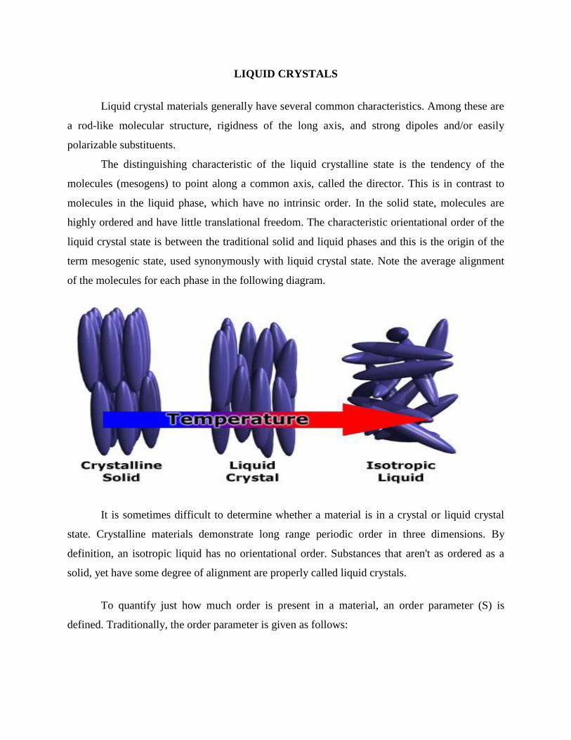
The distinguishing characteristic of the liquid crystalline state is the tendency of the
molecules (mesogens) to point along a common axis, called the director. This is in contrast to
molecules in the liquid phase, which have no intrinsic order. In the solid state, molecules are
highly ordered and have little translational freedom. The characteristic orientational order of the
liquid crystal state is between the traditional solid and liquid phases and this is the origin of the
term mesogenic state, used synonymously with liquid crystal state. Note the average alignment
of the molecules for each phase in the following diagram.
It is sometimes difficult to determine whether a material is in a crystal or liquid crystal
state. Crystalline materials demonstrate long range periodic order in three dimensions. By
definition, an isotropic liquid has no orientational order. Substances that aren't as ordered as a
solid, yet have some degree of alignment are properly called liquid crystals.
To quantify just how much order is present in a material, an order parameter (S) is
defined. Traditionally, the order parameter is given as follows:
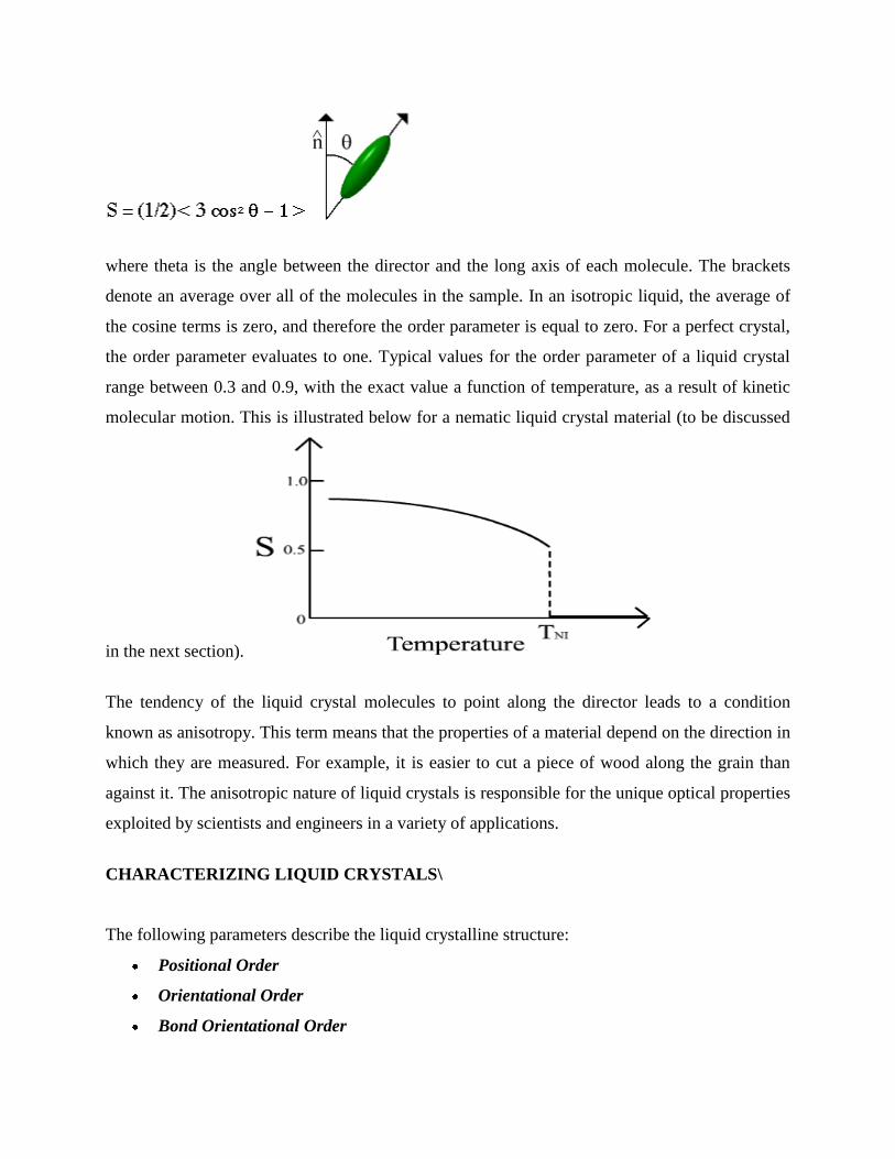
where theta is the angle between the director and the long axis of each molecule. The brackets
denote an average over all of the molecules in the sample. In an isotropic liquid, the average of
the cosine terms is zero, and therefore the order parameter is equal to zero. For a perfect crystal,
the order parameter evaluates to one. Typical values for the order parameter of a liquid crystal
range between 0.3 and 0.9, with the exact value a function of temperature, as a result of kinetic
molecular motion. This is illustrated below for a nematic liquid crystal material (to be discussed
in the next section).
The tendency of the liquid crystal molecules to point along the director leads to a condition
known as anisotropy. This term means that the properties of a material depend on the direction in
which they are measured. For example, it is easier to cut a piece of wood along the grain than
against it. The anisotropic nature of liquid crystals is responsible for the unique optical properties
exploited by scientists and engineers in a variety of applications.
CHARACTERIZING LIQUID CRYSTALS\
The following parameters describe the liquid crystalline structure:
Positional Order
Orientational Order
Bond Orientational Order
THERMOTROPIC PHASES
Thermotropic liquid crystals can generally be formed by prolate (calamitic) molecules or
oblate (discotic) molecules. Liquid crystal phases formed by calamitic molecules fall into
three different categories: nematic, chiral nematic, and smectic.
Nematic Liquid Crystal Phase
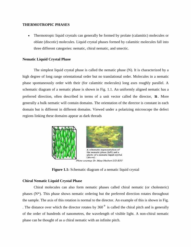
The simplest liquid crystal phase is called the nematic phase (N). It is characterized by a
high degree of long range orientational order but no translational order. Molecules in a nematic
phase spontaneously order with their (for calamitic molecules) long axes roughly parallel. A
schematic diagram of a nematic phase is shown in Fig. 1.1. An uniformly aligned nematic has a
preferred direction, often described in terms of a unit vector called the director, . More
generally a bulk nematic will contain domains. The orientation of the director is constant in each
domain but is different in different domains. Viewed under a polarizing microscope the defect
regions linking these domains appear as dark threads
Figure 1.1: Schematic diagram of a nematic liquid crystal
Chiral Nematic Liquid Crystal Phase
Chiral molecules can also form nematic phases called chiral nematic (or cholesteric)
phases (N*). This phase shows nematic ordering but the preferred direction rotates throughout
the sample. The axis of this rotation is normal to the director. An example of this is shown in Fig.
. The distance over which the director rotates by 360 is called the chiral pitch and is generally
of the order of hundreds of nanometres, the wavelength of visible light. A non-chiral nematic
phase can be thought of as a chiral nematic with an infinite pitch.
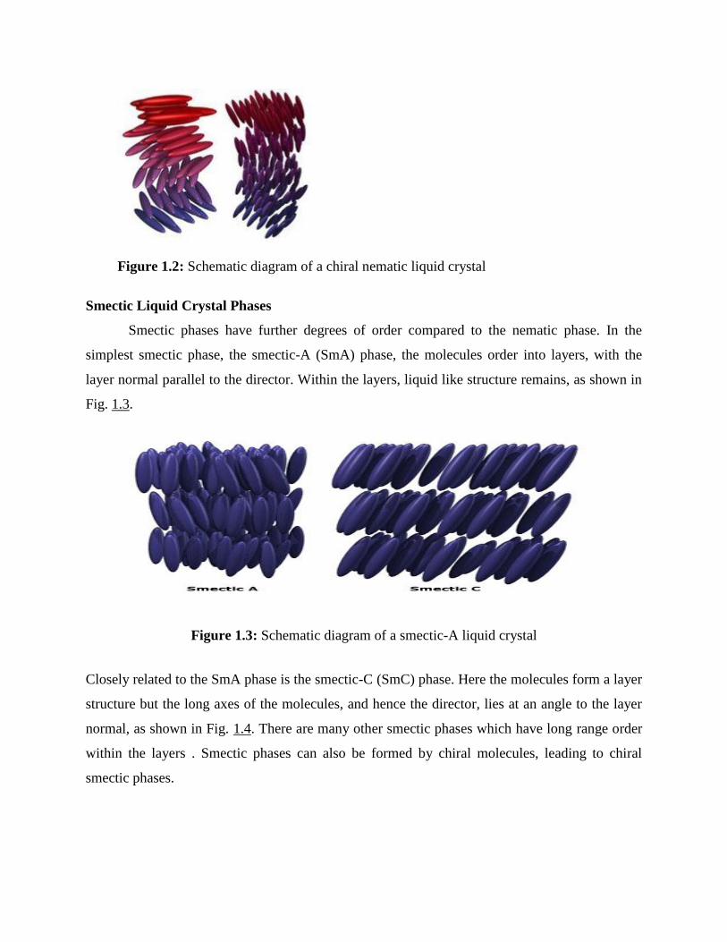
Figure 1.2: Schematic diagram of a chiral nematic liquid crystal
Smectic Liquid Crystal Phases
Smectic phases have further degrees of order compared to the nematic phase. In the
simplest smectic phase, the smectic-A (SmA) phase, the molecules order into layers, with the
layer normal parallel to the director. Within the layers, liquid like structure remains, as shown in
Fig. 1.3.
Figure 1.3: Schematic diagram of a smectic-A liquid crystal
Closely related to the SmA phase is the smectic-C (SmC) phase. Here the molecules form a layer
structure but the long axes of the molecules, and hence the director, lies at an angle to the layer
normal, as shown in Fig. 1.4. There are many other smectic phases which have long range order
within the layers . Smectic phases can also be formed by chiral molecules, leading to chiral
smectic phases.
Discotic Liquid Crystal Phases
Liquid crystal phases formed by discotic molecules fall into three different categories:
discotic nematic, discotic chiral nematic, and columnar . The discotic nematic is similar in
structure to the calamitic nematic, although in this case the short axes of the molecules tend to lie
parallel. The same holds for the discotic chiral nematic phases.
Columnar phases are the discotic equivalent of the smectic phase. Here the molecules
form columns. In the simplest case the short axes of the molecules lie parallel to the axis of the
column and the columns are randomly distributed in space. More complicated discotic phases
exist, where the short molecular axes lie at an angle to the column and translational order exists
between the columns, analogous to the more complicated smectic phases.
OTHER THERMOTROPIC PHASES
Most of the phases exhibited by low molecular mass liquid crystals are described above.
Recently however there has been much interest in the so-called `banana' phases formed by bent-
core molecules Some of these phases are chiral although the molecules forming them are achiral.
Some high molecular mass polymers, liquid crystalline polymers (LCP), can also form
liquid crystal phases . These fall into two categories depending on where the mesogenic part of
the molecule is located. If the mesogenic unit is contained within the main polymer chain then it
is termed a main chain liquid crystal polymer (MCLCP). If it is attached to a side chain of the
polymer then it is termed a side chain liquid crystal polymer (SCLCP). As well as depending on
the nature of the mesogenic core, the mesophases formed by these materials are dependent on the
flexibility of the polymer backbone and (for SCLCP's) the side chain.
Closely related to LCP's are dendritic liquid crystals . These molecules consist of a
central core with the mesogenic units attached to flexible spacers that radiate out from the core.
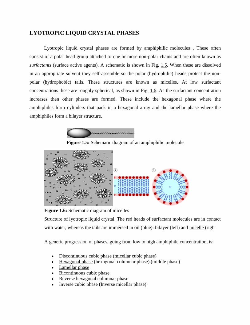
LYOTROPIC LIQUID CRYSTAL PHASES
Lyotropic liquid crystal phases are formed by amphiphilic molecules . These often
consist of a polar head group attached to one or more non-polar chains and are often known as
surfactants (surface active agents). A schematic is shown in Fig. 1.5. When these are dissolved
in an appropriate solvent they self-assemble so the polar (hydrophilic) heads protect the non-
polar (hydrophobic) tails. These structures are known as micelles. At low surfactant
concentrations these are roughly spherical, as shown in Fig. 1.6. As the surfactant concentration
increases then other phases are formed. These include the hexagonal phase where the
amphiphiles form cylinders that pack in a hexagonal array and the lamellar phase where the
amphiphiles form a bilayer structure.
Figure 1.5: Schematic diagram of an amphiphilic molecule
Figure 1.6: Schematic diagram of micelles
Structure of lyotropic liquid crystal. The red heads of surfactant molecules are in contact
with water, whereas the tails are immersed in oil (blue): bilayer (left) and micelle (right
A generic progression of phases, going from low to high amphiphile concentration, is:
Discontinuous cubic phase (micellar cubic phase)
Hexagonal phase (hexagonal columnar phase) (middle phase)
Lamellar phase
Bicontinuous cubic phase
Reverse hexagonal columnar phase
Inverse cubic phase (Inverse micellar phase).
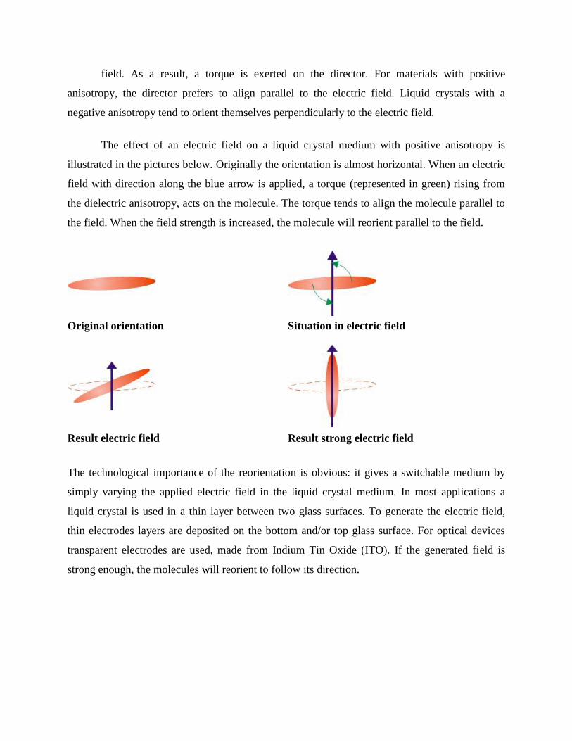
field. As a result, a torque is exerted on the director. For materials with positive
anisotropy, the director prefers to align parallel to the electric field. Liquid crystals with a
negative anisotropy tend to orient themselves perpendicularly to the electric field.
The effect of an electric field on a liquid crystal medium with positive anisotropy is
illustrated in the pictures below. Originally the orientation is almost horizontal. When an electric
field with direction along the blue arrow is applied, a torque (represented in green) rising from
the dielectric anisotropy, acts on the molecule. The torque tends to align the molecule parallel to
the field. When the field strength is increased, the molecule will reorient parallel to the field.
Original orientation Situation in electric field
Result electric field Result strong electric field
The technological importance of the reorientation is obvious: it gives a switchable medium by
simply varying the applied electric field in the liquid crystal medium. In most applications a
liquid crystal is used in a thin layer between two glass surfaces. To generate the electric field,
thin electrodes layers are deposited on the bottom and/or top glass surface. For optical devices
transparent electrodes are used, made from Indium Tin Oxide (ITO). If the generated field is
strong enough, the molecules will reorient to follow its direction.

Light propagation in an isotropic medium
For the uniaxial liquid crystal medium, an electric field feels a different refractive index when it
oscillates in the plane perpendicular to the director or along the director. This uniaxial anisotropy
of the refractive index is called birefringence. Birefringence allows to manipulate the
polarization of the light propagating through the medium.
The elliptical polarization of light entering a liquid crystal medium must be decomposed
into two linear polarizations called the ordinary and the extra-ordinary mode. Along these two
directions, the two linearly polarized modes feel a different refractive index. Therefore, they
propagate through the liquid crystal with a different speed as illustrated in the picture below.
Light propagation in a birefringent medium
In the isotropic medium, the two parts propagated with the same speed. Combining them
back together will result in the same polarization ellipse as the original. In birefringent media,
the different speed of the ordinary and extra-ordinary waves results in a phase difference
between the two modes (= retardation). At the end of the medium this phase difference between
the two oscillations will result in a different polarization ellipse.
Switchable birefringence
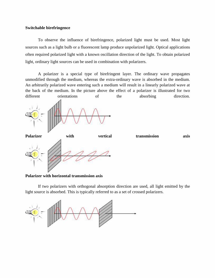
To observe the influence of birefringence, polarized light must be used. Most light
sources such as a light bulb or a fluorescent lamp produce unpolarized light. Optical applications
often required polarized light with a known oscillation direction of the light. To obtain polarized
light, ordinary light sources can be used in combination with polarizers.
A polarizer is a special type of birefringent layer. The ordinary wave propagates
unmodified through the medium, whereas the extra-ordinary wave is absorbed in the medium.
An arbitrarily polarized wave entering such a medium will result in a linearly polarized wave at
the back of the medium. In the picture above the effect of a polarizer is illustrated for two
different orientations of the absorbing direction.
Polarizer with vertical transmission axis
Polarizer with horizontal transmission axis
If two polarizers with orthogonal absorption direction are used, all light emitted by the
light source is absorbed. This is typically referred to as a set of crossed polarizers.

Crossed polarizers
Birefringence is important for modifying and controlling the polarization of light
propagating through the medium. A liquid crystal layer inserted between crossed polarizers can
change the polarization of the light propagating through, which results in light transmission after
the crossed polarizers.
A liquid crystal layer between crossed polarizers
Because the director can be controlled using an electric field, a liquid crystal is a controllable
birefringent medium. Therefore, the polarization state of the light after the liquid crystal layer
can be changed and hence the intensity of the transmission through the crossed polarizers is
adapted.
Choosing the preferential direction of the molecules
In a glass vessel a liquid crystal appears as an opaque milky fluid. The random variation
of the director in the material on a micrometer scale is the main cause of the light scattering.
For applications, it is important to obtain a region free of defects with a known director
distribution. Therefore, liquid crystals are usually handled in thin layers between two substrates.
Control of the director at the surfaces allows reproducible director orientations as illustrated
below. The fixed orientation of the surface director forces the director in the bulk to follow this
direction. Two commonly used types of alignment are planar and homeotropic alignment. In
planar alignment the surface director is oriented parallel to the surface, for homeotropic
alignment it is oriented perpendicular to the surface.
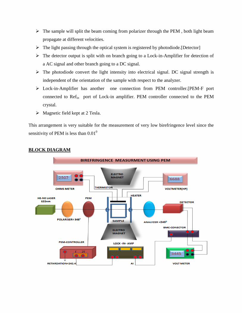
The sample will split the beam coming from polarizer through the PEM , both light beam
propagate at different velocities.
The light passing through the optical system is registered by photodiode.[Detector]
The detector output is split with on branch going to a Lock-in-Amplifier for detection of
a AC signal and other branch going to a DC signal.
The photodiode convert the light intensity into electrical signal. DC signal strength is
independent of the orientation of the sample with respect to the analyzer.
Lock-in-Amplifier has another one connection from PEM controller.[PEM-F port
connected to Refin port of Lock-in amplifier. PEM controller connected to the PEM
crystal.
Magnetic field kept at 2 Tesla.
This arrangement is very suitable for the measurement of very low birefringence level since the
sensitivity of PEM is less than 0.010
BLOCK DIAGRAM
The profile of transmitted intensity on cooling or heating the sample in equal temperature
step is recorded from isotropic phase down to appropriate temperature.
The transmitted intensity is an oscillatory function within maxima minima occurring for
∆ф = (2m+1) π and 2mπ respectively. The consecutive maxima minima get broadened
with lowering of temperature. The value of transmitted intensity is nearly zero in the
isotropic phase as expected.
Now isotropic phase is taken as nil phase difference and the first maximum occurs at π
and minimum at 2π and so on. From isotropic to first maximum, we calculated ∆n
directly from the formula. In going from π to 2π. we have subtracted 360 from the ∆ф
using I= Io (1-Cos∆ф)/2. In going from 2π to 3π, we added 2π to ∆ф and in going from
3π to 4π we subtracted π from ∆ф and then added 3π to it. This ∆ф value is used to
calculate ∆n. then we plotted the graphs between ∆n and temperature.
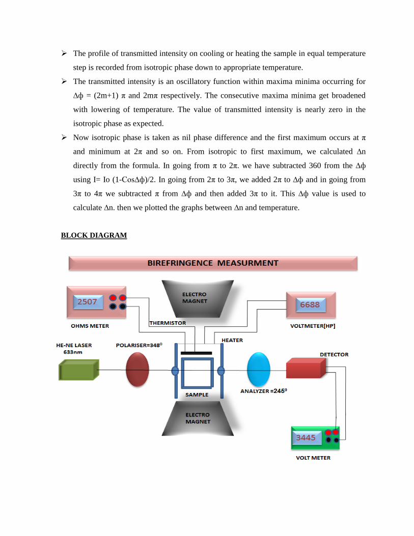
BLOCK DIAGRAM


![Magnetic quasi-static simulation [coreless liquid-cooled motor]](https://img.pdfslide.us/doc/110x75/56816864550346895ddeb859/magnetic-quasi-static-simulation-coreless-liquid-cooled-motor.jpg)