Embed Size (px)
Citation preview

The contents of this literature are as of Jun 2017 Magnescale reserves the right to change product specifications without prior notice.This catalog is printed with soy ink.MGS-LS-1706-EN-C
http://www.magnescale.com
Magnescale Co., Ltd.
HeadquartersInternational Sales DepartmentMagnescale Americas Inc. Magnescale Europe GmbH Service & Parts
45 Suzukawa, Isehara-shi, Kanagawa 259-1146, Japan45 Suzukawa, Isehara-shi, Kanagawa 259-1146, Japan5740 Warland Drive, Cypress, CA 90630, USAAntoniusstrasse 14, 73249 Wernau, Germany45 Suzukawa, Isehara-shi, Kanagawa 259-1146, Japan
TEL.+81 (0)463 92 1011TEL.+81 (0)463 92 7971TEL.+1 (562)594 5060TEL.+49(0)7153 934 291TEL.+81 (0)463 92 2132
FAX.+81 (0)463 92 1012FAX.+81 (0)463 92 7978FAX.+1 (562)594 5061FAX.+49(0)7153 934 299FAX.+81 (0)463 92 3090
:::::
E-mail : [email protected] : [email protected] : [email protected] : [email protected]

2 3
PD LD
Laserscale
TraceabilityTraceability Flow Chart (Length)
National Primary Standards
National Institute of Advanced Industrial Science and Technology (AIST)
International Committee for Weightsand Measures (CIPM)
International Bureau of Weights and Measures (BIPM)
NationalSecondaryStandards
ManufacturingReferenceStandard
Iodine saturation absorption stabilized He-Ne laser at 633nm
Magnescale Co., Ltd.
Products
Stabilized He-Ne Laser (633nm)
Nationalstandards
Optical comb
Safety
We have met:
Our products comply with CE Marking requirements, have acquired UL certifications and meet other regulations, ensuring safe use the world over.
* When using our devices with machines to which the European Machinery Drirective applies, please make sure that the devices when installed on the machines fulfil the applicable requirements of the Directive.
* Standards or regulations to be complied with may vary by product.
•EMC Directives(CE) EMI: EN 55011 Group 1 Class A EMS: EN 61000-6-2
•FCC regulation FCC Part 15 Subpart B Class A
for Products with built-in AC power supply:• UL61010-1 • EN61010-1
for Products with Laser:• DHHS (21CFR1040.10) • IEC60825-1
The total quality control system that operates throughout the entire design and production process ensures products with enhanced safety, high quality, and high reliability that match our customers’ requirements. The company is certified for length calibration in compliance with the traceability system required by the “Weights and Measures Act,” and has been granted ISO 9001 certification, which is the international standard for quality assurance.
No compromise for high-accuracy products
Safety
Traceability
Contents
Introduction
Principle
Application
Lineup
BS78
BS65-R
BH25-RE /BH25-NE
BH20-RE /BH20-NE
BL57-RE /BL57-NE
BD96
BD95
Connection Cable
Technology
2
2
3
4
6
7
8
10
14
16
18
20
26
27
28
29
* The product name "Laserscale" is trademark of Magnescale Co., Ltd.
Contents

4 5
138nm
What's Lasers cale?The world of super-resolution is going further than 1nmLaserscale easily achieves measurement and control with ultra high resolution of better than 1nm. A sinusoidal wave (approximately 138nm signal pitch) is generated using the grating interference method by utilizing a holographic scale with high diffraction efficiency and a high resolution head. The BS series offers strong resistance to disturbance by air pressure or current, and is easy to install. Signal distortion, in principle, remains minimal at a high S/N ratio. Resolution of 17pm can be achieved using our automatic compensation interpolator.
High-resolution scale with signal pitch of approx. 138nm outperforms light wave interferometer systems High stability : Free from temperature, air pressure, or air disturbances Easy installation & maintenance
High stability against external disturbances (air pressure disturbances/fluctuations)
BS seriesSignal pitch:
138nm
Model Output
Binary
Max. divisions
8000
Resolutions
17 pm
Max. response speed
400mm/s
Unaffected by the change of clearance between head & scaleEasy installation
Clearance change
Track directionClearance direction
Air pressure effect
Posi
tion
(40n
m/d
iv)
Laserinterferometer
Laserscale
Time(min)0 800
Lissajous figure
Optical axis shiftby track direction
[Easy installation & maintenance]Large installation tolerancesEasy installation and non-contact detection
No electrical adjustment after installationDespite the high installation tolerances, no electrical adjustment is required after installation.
Protected holographic gratingThe holographic grating is protected by glass covers which guard the grating against external pressure. The glass can be wiped to clean dust and dirt.
Ultra-high resolutionVolume holography technology of Laserscale achieves high diffraction efficiency to generate a high S/N signal and a strong output signal.
Best in class 17pm resolutionOne count movement of the 0.55μm holographic grating pitch diffracts the signal to 4 periods. The 1/4 of the original signal results in a signal of approximately 0.138μm. Using our interpolator, this signal can achieve 17pm resolution.
Ultra-high resolution and high response speedOur grating interference principle linear encoders offer a signal pitch of approximately 0.14μm. That is 1/140th of a conventional linear encoder with a 20μm signal pitch. Using our interpolator, 17pm resolution and a response speed of up to 400mm/s is achievable.
A/B quadrature 32 60mm/s4.31 nm
Holographic grating
Holographic scale
Cover glass
PD LDPD LD
Yawing direction:±6min
Pitching direction:±6min
Rolling direction:±10min
Track direction:±0.2mm
BL Series

6 7
Laser beam is radiated from LD (semiconductor laser). Laser is divided into P wave and S wave.
Laser beam passage(Transmission)
Principle
Laser is diffracted by holographic grating.
The semiconductor laser beam is split by a polarized light beam splitter into S and P polarized light beams, then diffracted through a volume holographic grating with very high diffraction efficiency. The two diffracted beams pass through separate 1/4-wavelength plates to a mirror, which reflects the beams back through the plates. This process converts the S polarized beam to P polarized light and the P polarized beam to S polarized light.The two beams are diffracted again through the volume holographic grating, then super-positioned by the polarized light beam splitter to create interference. All interference travels to the photo-detector side due to conversion of the polarization direction.Since double diffraction adds +2 Kx and -2 Kx phases to each beam, the interference is subject to four light-dark inversion cycles for each grating scale of movement. Thus a grating pitch of 0.55 μm produces a signal pitch of 0.55/4 = approx. 0.138 μm.This detecting optics is free from fluctuations and change in air pressure, since the light path of both left and right changes identiacally even with the change in wavelength of the optical source. Repeatability and returning errors do not occur in principle.
P wave and S wave are piled on and enters into the photo detector.
Similarly, the laser is diffracted by the holographic grating.
P wave is converted to S wave.S wave is converted to P wave.
<BS Series>
: Direction where light vibrates···Right and left : Direction where light vibrates···Back and forth
Photo detectorSemiconductor laserWavelength: 790nm
ei( -2Kx)
Polarization beamsplitter
Holographic gratingLaserscale
Pitch 0.55 μm
-K
-K
+K
+Kp
Mirror
K=
X
Polarizing plateei ( +2Kx)
/4 phase plate
Aligner
EUVEB
DUV
Aspherical surface
processing machine
Microgrinder
Precisionlathe
Semiconductorapplications
Dicers
Bonders
Prober
Precisionmeasurement
inspectionapplications
Filminspectionequipment
Defectinspectionequipment
Electronmicroscopes
Media
Head tester
Optical disk
STW
Ultra high precision air stages(vacuum resistant)
Surface roughness/contour measuring machines
DUV-based automatic waferdefect classification systems
Non-contact measuring machines Micro grinders Aspherical surface machining
Application
Precision machiningapplications
Marketfor ultraprecise
positioning

8 9
BS =approx. 138nm
Transmission
BH =250nmReflection
BL =400nm
Transmission
Series Feature Max. response speed Page
LineupMinimum resolution Measuring length Interpolator OutputScale accuracy
40bit Binary
Serial
BS78 Low expansion glass 400mm/s P.1017pm 10mm~420mmBD96(BD95)
±0.04μm(Measuring length 40mm)
40bit Binary
Serial
BH25-RE/NELow expansion glass
Soda-lime glass700mm/s P.1631.25pm
Low expansion glass:30mm~420mmSoda-lime glass:30mm~420mm
BD96
±0.5μm(30mm-170mm)
±1μm(220mm-420mm)
0.4μm (1Vp-p) 3,000mm/sNONE Analog
P.20
BL57-NELow expansion glass
Soda-lime glass
0.1/0.05/0.02/0.01μm
1,500, 650, 300,120mm/s
Built-in I/F Box A/B quadrature
0.4μm (1Vp-p) 3,000mm/sNONE Analog
0.1/0.05/0.02/0.01μm
1,500, 650, 300,120mm/s
Built-in I/F Box A/B quadrature
BL57-RELow expansion glass
Soda-lime glass
±0.5μm (30mm-160mm)±1μm (210mm-360mm)
±1.5μm (410mm-1,060mm)
Low expansion glass:30mm~410mmSoda-lime glass:60mm~1,060mm
Please ask for more than 1,060mm
±0.5μm (30-170mm)±1μm (220-370mm)
±1.5μm (420-1,060mm)
Low expansion glass:30mm~420mmSoda-lime glass:60mm~1,060mm
Please ask for more than 1,060mm
40bit Binary
Serial
BH20-RE/NE
302,400Pulse/rotation680,400Pulse/rotation907,200Pulse/rotation
1,048,576Pulse/rotation
P.181.5nrad
Radius 12.03mmRadius 27.07mmRadius 36.10mmRadius 41.72mm
BD96-555min-1
( )1,428min-1, 634min-1
476min-1, 411min-1
40bit Binary
Serial
BS65-RLong length typeSoda-lime glass
400mm/s P.1417pm 160mm~960mmBD96(BD95)
L<460:(0.1+0.4L/100)μmp-p
L>460:3μmp-pL:Measuring length(mm)
=

10 11
Actual size
BS BS78(with/without reference point)
High-speed and high-resolution, while maintaining stable, ultraprecision measuring.
Ideal for precision stages, semiconductor inspection/manufacturing systems,
and ultraprecision processing machines.
• High-resolution scale with signal pitch of approx. 138nm,
outperforming light wave interferometer systems
• High stability, unaffected by humidity, air pressure and air disturbances
• Reference point accuracy : ±0.1μm
• Scale accuracy : ±0.04μm (measuring length : 40 mm)
• Non-contact design eliminates return error.
• Special non-magnetic and vacuum-compatible models available
• Using low expansion glass : -0.7 x 10⁻⁶/ ˚C
(measuring length : 10 to 420 mm)
Type example : BS78-220R
R: with reference point; RS: high accuracy with reference pointN: without reference point; NS: high accuracy without reference point
Measuring length
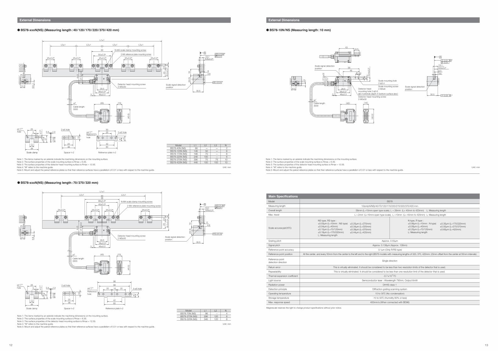
External Dimensions
Unit: mm
ModelBS78-40R (RS)BS78-120R (RS)BS78-170R (RS)BS78-220R (RS)BS78-370R (RS)BS78-420R (RS)
L166
146196246396446
L2—5075
10075
100
L3————75
100
N2666
1010
Unit: mm
ModelBS78-70R (RS)BS78-270R (RS)BS78-320R (RS)
L196
296346
L2—
120120
N488
BS78-xxxR(RS) (Measuring length : 40 / 120 / 170 / 220 / 370 / 420 mm)
BS78-xxxR(RS) (Measuring length : 70 / 270 / 320 mm)
Note 1: The items marked by an asterisk indicate the machining dimensions on the mounting surface.Note 2: The surface properties of the scale mounting surface is Rmax = 6.3S.Note 3: The surface properties of the detector head mounting surface is Rmax = 12.5S.Note 4: "M" refers to the machine guide.Note 5: Mount and adjust the paired reference plates so that their reference surfaces have a parallelism of 0.01 or less with respect to the machine guide.Note 6: Reference point detection direction : Standard (Scale movement direction with the head stationary)
Note 1: The items marked by an asterisk indicate the machining dimensions on the mounting surface.Note 2: The surface properties of the scale mounting surface is Rmax = 6.3S.Note 3: The surface properties of the detector head mounting surface is Rmax = 12.5S.Note 4: "M" refers to the machine guide.Note 5: Mount and adjust the paired reference plates so that their reference surfaces have a parallelism of 0.01 or less with respect to the machine guide.Note 6: Reference point detection direction : Standard (Scale movement direction with the head stationary)
Scale clamp
255
1238
ø4 hole+0.05 0
4+0.0
5 0 1.4
13.82116
0.4
2538
Spacer t=2
10
2-ø5 hole
Referencehole
2550
4260
9 14
3-ø5 holeø4+0.05 0
Reference plate t=2
6.813.3
13.3
6.8
Reference point detection position
Scale signal detection position
4.6
6
13.19.8±0.2*
30.5
145
0.03
0.010.01
*
(45) (15)
(40.
5)
ø7Cable length3000
25±0.2*
39.2
±0.2
*5
1423
25±0.2*25±0.2*25±0.2*25±0.2*
Scale movementReference pointdetection direction
L3±1 L3±1L2±1 L2±1
L1±1
50±3*
60
2-M4 reference plate mounting screw
N-M4 scale clamp mounting screw
38±0.2*46±0.33
29.5Detector head mounting screw2-M3x30
43.5
32.7
±0.3
Reference point detection position
Scale signal detection position30.5
6145
4.6
0.010.01
0.03
9.8±0.2*13.1
ø7
Cable length3000
(15)(45)
(40
.5)
38±0.2*46±0.3
29.5
3
Detector head mounting screw2-M3x30
39.2
±0.2
*145
23
43.5
32.7
±0.3
25±0.2* 25±0.2* 25±0.2* 25±0.2*Scale movementReference pointdetection direction
40±0.2*88±0.3*
98
L1±1
L2±1 L2±1
N-M4 scale clamp mounting screw
2-M4 reference plate mounting screw
Spacer t=2
10
2538
2-ø5 hole
Reference plate t=2
4260
9 14
5-ø5 hole25 15 25
88
98
Referencehole
ø4+0.05 0
Scale clamp
3812
16 21
1.40.4
13.8
255
ø4+0.05 0
4+0.0
5 0
hole
*
*
*
12 13
Measuring length
Overall length
Max. travel
Single direction
0.1μm (Only R/RS type)
At the center, and every 50mm from the center to the left and to the right (BS78 models with measuring lengths of 320, 370, 420mm: 20mm offset from the center at 50mm intervals)
This is virtually eliminated. It should be considered to be less than two resolution limits of the detector that is used.
This is virtually eliminated. It should be considered to be less than one resolution limit of the detector that is used.
-0.7 x 10⁻⁶/˚C
Semiconductor laser : Wavelength 790nm, Output 6mW
DHHS class 1
Diffraction grating scanning system
10 to 30˚C (No condensation)
-10 to 50˚C (Humidity 60% or less)
400mm/s (When connected with BD96)
Main SpecificationsModel BS78
Scale accuracy(at20˚C)
10(onlyN/NS)/40/70/120/170/220/270/320/370/420 mm
58mm (L=10mm:open type scale), L + 26mm (L= 40mm to 420mm)
L + 2mm (L=10mm:open type scale), L +10mm (L= 40mm to 420mm)
NS type, RS type :±0.03μm (L=10mm : NS type) ±0.04μm (L=40mm)±0.10μm (L=70/120mm)±0.18μm (L=170/220mm)L: Measuring length
±0.25μm (L=270mm) ±0.34μm (L=320mm)±0.39μm (L=370mm)±0.44μm (L=420mm)
N type, R type :±0.06μm (L=10mm : N type) ±0.08μm (L=40mm)±0.20μm (L=70/120mm)L: Measuring length
±0.35μm (L=170/220mm)±0.50μm (L=270/370mm)±0.65μm (L=420mm)
Grating pitch
Signal pitch
Approx. 0.55μm
Approx. 0.138μm (Approx. 138nm)
Reference point detection direction
Reference point accuracy
Reference point position
Return error
Repeatability
Thermal expansion coefficient
Light source
Radiation power
Detection principle
Operating temperature
Storage temperature
Max. response speed
L: Measuring length
L: Measuring length
External Dimensions
Unit: mm
ModelBS78-40N (NS)BS78-120N (NS)BS78-170N (NS)BS78-220N (NS)BS78-370N (NS)BS78-420N (NS)
L166
146196246396446
L2—5075
10075
100
L3————75
100
N2666
1010
BS78-xxxN(NS) (Measuring length : 40 / 120 / 170 / 220 / 370 / 420 mm)
External Dimensions
BS78-10N/NS (Measuring length : 10 mm)
BS78-xxxN(NS) (Measuring length : 70 / 270 / 320 mm)
Unit: mm
ModelBS78-70N (NS)BS78-270N (NS)BS78-320N (NS)
L196
296346
L2—
120120
N488
Note 1: The items marked by an asterisk indicate the machining dimensions on the mounting surface.Note 2: The surface properties of the scale mounting surface is Rmax = 6.3S.Note 3: The surface properties of the detector head mounting surface is Rmax = 12.5S.Note 4: "M" refers to the machine guide.Note 5: Mount and adjust the paired reference plates so that their reference surfaces have a parallelism of 0.01 or less with respect to the machine guide.
Note 1: The items marked by an asterisk indicate the machining dimensions on the mounting surface.Note 2: The surface properties of the scale mounting surface is Rmax = 6.3S.Note 3: The surface properties of the detector head mounting surface is Rmax = 12.5S.Note 4: "M" refers to the machine guide.Note 5: Mount and adjust the paired reference plates so that their reference surfaces have a parallelism of 0.01 or less with respect to the machine guide.
13.3
6.8
9.8±0.2*
30.5
13.1
4.66
19(2
4.5)
0.010.01
0.03Scale signal detection position
ø4+0.05 0
4+0.0
5 0
Scale clamp
255
1238
16 21
0.4 1.4
13.8
hole
13.3 6.8
Spacer t=2
2538
10
2-ø5 hole
Reference plate t=2
Referencehole
5025
4260
9 14
3-ø5 holeø4+0.05 0
9.8±0.2*
30.5
13.1
64.619
(24.
5)
0.010.01
0.03Scale signal detectionposition
ø7Cable length3000
(45) (15)
(40.
5)
3
29.538±0.2*46±0.3
27.8
±0.3
43.5
Detector head mounting screw2-M3x30
39.2
±0.2
*5
1423
25±0.2*25±0.2*25±0.2*25±0.2*25±0.2*
L1±1
50±0.3*
60
L3±1 L3±1L2±1 L2±1
2-M4 reference plate mounting screw
N-M4 scale clamp mounting screw
3812
1.4
16 21
0.4
13.8
Scale clamp
ø4+0.05 0
4+0.0
5 0
255hole
Spacer t=2
10
2538
2-ø5 hole
4260
25 15 25
98
88
Reference plate t=2
9 14
5-ø5 holeReferencehole
ø4+0.05 0
ø7
Cable length3000
(15)(45)
(40.
5)
3
29.538±0.2*46±0.3
Detector head mounting screw2-M3x30
43.5
27.8
±0.3
145
39.2
±0.2
*
23
2-M4 reference plate mounting screw
N-M4 scale clamp mounting screw
L1±1L2±1 L2±1
40±0.2*88±0.3*
98
25±0.2*25±0.2*25±0.2*25±0.2*
*
*
*
*
Unit: mm
Note 1: The items marked by an asterisk indicate the machining dimensions on the mounting surface.Note 2: The surface properties of the scale mounting surface is Rmax = 6.3S.Note 3: The surface properties of the detector head mounting surface is Rmax = 12.5S.Note 4: "M" refers to the machine guide.Note 5: Mount and adjust the paired reference plates so that their reference surfaces have a parallelism of 0.01 or less with respect to the machine guide.
Scale signal detectionposition
Cable length3000
0.03 A
A
*30.5
13.1
0.01 M *0.01
9.8±0.2*6.54.6
Scale signal detectionposition
(45)φ7
13.3
6.8
(15)
(40
.5)
Detector head mounting hole 2-φ3.6φ6.4 sinkhole depth 4(bottom surface also)
Scale mounting hole2-φ3.4Scale mounting screw2-M3x829.5
38±0.2*
10.4
±0.2
*
8*
58
14.5
463
4 8
13.3
27.8
±03
46±0.33Detector head mounting screw2-M3x30
Magnescale reserves the right to change product specifications without prior notice.
43

14 15
Actual size
BS BS65-R(with reference point)
High accuracy Laserscale with built-in optical reference point
• Signal pitch of 138nm
• High accuracy, high resolution Scale accuracy : L < 460 : (0.1+0.4L / 100) μmp-p (L=measuring length in mm)
• High accuracy optical reference point : ±0.1μm
• Measuring length : 160 mm to 960 mm
• Easy installation
• Minimal effect from disrupted air current and atmospheric changes.Type example : BS65-360R
R: with reference point
Measuring length
External Dimensions
Unit: mm
ModelBS65-160RBS65-260RBS65-360RBS65-460RBS65-560RBS65-660RBS65-760RBS65-860RBS65-960R
L1196296396496596696796896996
L275
12075
12075
12075
12075
L3——75757575757575
N M——1122334
68
10121416182022
BS65-xxxR (Measuring length : 160 / 260 / 360 / 460 / 560 / 660 / 760 / 860 / 960 mm)
Measuring length
Overall length
Max. travel
160/260/360/460/560/660/760/860/960 mm
Measuring length + 36mm
Measuring length + 10mm (5mm on each side)
Main SpecificationsModel BS65-R
L < 460 : (0.1 + 0.4L/100) μm p-p , L ≧ 460 : 3μm p-p L : Measuring length (mm)
Scale accuracy (at20˚C)
Reference point detection direction
Reference point accuracy
Reference point position
Return error
Repeatability
Thermal expansion coefficient
Light source
Radiation power
Detection principle
Operating temperature
Storage temperature
Max. response speed
Single direction
±0.1μm
At the center, and every 50mm from the center to the left and to the right
This is virtually eliminated. It should be considered to be less than two resolution limits of the detector that is used.
This is virtually eliminated. It should be considered to be less than one resolution limit of the detector that is used.
8 x 10⁻⁶/ ˚C
Semiconductor laser : Wavelength 790nm, Output 6mW
DHHS class 1
Diffraction grating scanning system
10 to 30˚C (No condensation)
-10 to 50˚C (Humidity less than 60%)
400mm/s (When connected with BD96)
Grating pitch
Signal pitch
Approx. 0.55μm
Approx. 0.138μm (Approx. 138nm)
Note 1: The items marked by an asterisk indicate the machining dimensions on the mounting surface.Note 2: The surface properties of the scale mounting surface is Rmax = 6.3S.Note 3: The surface properties of the detector head mounting surface is Rmax = 12.5S.Note 4: "M" refers to the machine guide.Note 5: Mount and adjust the paired reference plates so that their reference surfaces have a parallelism of 0.01 or less with respect to the machine guide.
0.01 M0.01
A
0.03 A
*
*
2040
719
20(3
9)
11.5±0.2*5
97
3.5 6
7.8
Spacer t=5
2-φ5 hole
10
25
38
Scale signal detection position
30.5
L2L2
2-M4 Reference plate mounting screwM-M4 Scale clamp mounting screw
When there is an even number of scale clamps(BS65-260R/460R/660R/860R)
25±0.2* 25±0.2*40±0.2*88±0.3*98
Cable length 3000
2-M5 Detector head mounting screw
2-M4 Reference plate mounting screw
M-M4 Scale clamp mounting screw
(45)
(40.
5)
(15)
70
55±0.3*
25±0.2*50±0.3*
60
25±0.2*25±0.2*25±0.2* 25±0.2* 25±0.2* 25±0.2*
L2
L3L3
L2L3×N L3×N
L1
2314 5
44.5
±0.3
*12
Reference plate t=5
3-φ5 hole5025
4260
9 14
φ4 +0.05 0
Referencehole
Scale Clamp
525
0.4 1.4
13.812
38
16 21
φ4 hole+0.05 0 4+0
.05
0
Reference plate t=5
5-φ5
4260
1525 25
88
98
9 14
φ4 +0.05 0
Referencehole
Magnescale reserves the right to change product specifications without prior notice.

16 17
Actual size
BH BH25-RE / BH25-NE(with/without reference point)
High-accuracy, reflective Laserscale with signal pitch of 250nm
Ideal for low-profile stages, semiconductor back-end processing equipment
and precision microscopes
• Signal pitch : 250nm
• High accuracy : ±1μm/420mm
• High response speed : 700mm/s
• Minimum resolution : 0.03125nm
• Available : with/without reference point
• Completely non-contact design : Return error is theoretically eliminated.
• Scale : Soda-lime glass/Low expansion glass
• Thin head with thickness of 12mm
• Supporting various resolutions and output modes
(Depending on the interpolator connected.)
• Special vacuum-compatible models available
Type example : BH25-170REDB
Measuring length
B: Soda-lime glass; C: Low expansion glass
R: with reference point; N: without reference point
E: Open type scale
BD96 connection
*Contact us directly for detail specifications
External Dimensions
Overall length
Max. travel
Scale accuracy (at 20˚C)
Grating pitch
Signal pitch
Reference point
Reference point detection direction
Output signal
Resolution
Thermal expansion coefficient
Light source
Detection principle
Operating temperature
Storage temperature
Max. response speed
Measuring length +26mm
Measuring length +10mm
±0.5μm (30 to 170mm) ±1.0μm (220 to 420mm)
1.0μm
0.25μm (250nm)
Interpolator BD96
BD96 connection(Depend on the number of divisions )
-0.7 x 10⁻⁶/ ˚C (Low expansion glass) 8 x 10⁻⁶/ ˚C (Soda-lime glass)
Semiconductor laser : Wavelength 790nm, Output 6mW
Diffraction grating scanning system
10 to 30˚C (No condensation)
-10 to 50˚C (Humidity less than 60%)
700mm/s (When connected with BD96)
Main SpecificationsModel BH25-RED BH25-NED
Measuring length 30/70/120/170/220/270/320/370/420 mm (Low expansion glass/Soda-lime glass)
None
None
With reference point
Single direction
BH25-xxxREDB (Measuring length : 30 / 70 / 120 / 170 / 220 / 270 / 320 / 370 / 420 mm)
BH25-xxxREDC (Measuring length : 30 / 70 / 120 / 170 / 220 / 270 / 320 / 370 / 420 mm)
Note 1: The items marked by an asterisk indicate the machining dimensions on the mounting surface. Note 2: The surface properties of the scale mounting surface is Rmax = 6.3S.Note 3: The surface properties of the detector head mounting surface is Rmax = 6.3S. Note 4: "M"refers to the machine guide.Note 5: Mount and adjust the reference plate so that their reference surfaces have a parallelism of 0.01 or less with respect to the machine guide.
Model nameBH25-003REDBBH25-007REDBBH25-012REDBBH25-017REDBBH25-022REDBBH25-027REDBBH25-032REDBBH25-037REDBBH25-042REDB
Measuring length3070
120170220270320370420
L15696
146196246296346396446
L2——5075
10012012075
100
L3———————75
100
P2466688
1010
SP——2222244
SC123334455
Note 1: The items marked by an asterisk indicate the machining dimensions on the mounting surface. Note 2: The surface properties of the scale mounting surface is Rmax = 6.3S.Note 3: The surface properties of the detector head mounting surface is Rmax = 6.3S. Note 4: "M"refers to the machine guide.Note 5: Mount and adjust the reference plate so that their reference surfaces have a parallelism of 0.01 or less with respect to the machine guide.
Model nameBH25-003REDCBH25-007REDCBH25-012REDCBH25-017REDCBH25-022REDCBH25-027REDCBH25-032REDCBH25-037REDCBH25-042REDC
Measuring length3070
120170220270320370420
L15696
146196246296346396446
L2——5075
10012012075
100
L3———————75
100
P2466688
1010
SP——2222244
SC123334455
Unit: mm
10
2538
Spacer (t=5)
2-ø5 hole
For BH25-003REDB, 012REDB, 017REDB, 022REDB, 037REDB, and 042REDB
1.45
11.3
13.512
18.5
0.3
38
25
4
Scale clamp
11.5
6.5
5025
2 4260
Reference plate (BE-A) (t=5)
Referencehole
3-ø5 hole
1.5
6.5
11.5
25
60
98
25 1588
42
5-ø5 hole
Unit: mm
Scale signal detection position
43.59
515
*(2
1)*
611.7
1.8±0.02*(19.5)
(26)
M0.020.01/200
6±0.
5
0.01M0.01
Reference plate(BE-C)
40
30101
Scale abutting surface
L1±1L3
2-M4x10
98L2L2 L3
P-4x10
Reference signal detection position
Scale signal detection position
11.5
20
2.5 20±0.1*25
2.5
21±0
.1*
26
Cable length 1000
(Note 5)
Reference plate(BE-C)mounting screw
Scale clamp mounting screw
SP-SpacerSC-Scale clamp
12.5
25±0.2* 25±0.2* 25±0.2* 25±0.2*25±0.2* 25±0.2*
88±0.3*40±0.2*
96±0.1*
4-ø2.8(Mounting hole for M2.6)
33±0
.1*
Abutting surface for mounting
10
2538
Spacer (t = 2.2)
2-ø5 hole
Reference plate(BE-A)
2-M4x10
60L2L2
Reference plate(BE-A)mounting screw
50±0.3*25±0.2*
For BH25-003REDC, 012REDC, 017REDC, 022REDC, 037REDC, and 042REDC
Reference platemounting screw
Reference plate
2-M4X8
60L2L2
50±0.3*25±0.2*
1.5
6.5
11.5
25
60
98
25 1588
42
+0.05 0ø4
5-ø5 hole
Reference plate (W) (t = 2.2)For BH25-007REDC, 027REDC and 032REDC
Reference hole
11.5
6.5
5025
2 4260
Reference plate (t = 2.2)
3-ø5 hole+0.05 0ø4
Referencehole
1.45
11.3
13.512
18.5
0.3
38
25
4
Scale clamp
+0.05 0ø4 hole
(26)
11.73.4
9 43.5
Scale signal detection position1.8±0.02*(16.9)
M0.020.01/200
6±0.
5
M0.010.01
515
*(2
1)*
Reference planefor mounting
2.5
20
Reference plate(W)
40
30101
Scale abutting surface
L1±1L3
2-M4x8
98L2L2 L3
P-4x8
Reference signal detection position
Scale signal detection position
11.5
2.5 20±0.1*
25
21±0
.1*
26
Cable length 1000
(Note 5)
Reference plate(W)mounting screw
Scale clamp mounting screw
SP-SpacerSC-Scale clamp
25±0.2* 25±0.2* 25±0.2* 25±0.2* 25±0.2* 25±0.2*
88±0.3*40±0.2*
4-ø2.8
33±0
.1*
96±0.1*(Mounting hole for M2.6)
12.5
Abutting surface for mounting
Penetrating 2-M3For mounting detector head
Abutt
ing su
rface
for m
ountin
g
Reference plate (BE-C) (t=5)For BH25-007REDB, 027REDB and 032REDB
+0.05 0ø4
Reference hole+0.05 0ø4+0.05
0ø4 hole
Reference planefor mounting
Penetrating 2-M3For mounting detector head
Abutt
ing su
rface
for m
ounti
ng
Magnescale reserves the right to change product specifications without prior notice.

Actual size*Lateral cable exit
18 19
BH BH20-RE / BH20-NE(with/without reference point)
Compact, reflective rotary Laserscale featuring high accuracy,
high resolution and high response speed.
Ideal for high-resolution angle measuring in HDD manufacturing equipment,
precision measuring instruments, and aspheric surface processing machines.
External Dimensions
BH20-NED
Unit: mmNote: The items marked by an asterisk indicate the machining dimensions on the mounting surface.
Straight cable exit Lateral cable exit
11.7
12.5
4.918.5
10214-52A2PL (Manufactured by 3M)
2-M3 (for mounting)
Cable length 100020±0
.1*
2.5
25
2.5 21±0.1*2631.9
50.555.2
30.5
31.7
12.4
11.7
12.5
4.9
Cou
ntin
g di
rect
ion
2-M2 (for mounting)8.85 (Scale signal detection position)
12.5
4
20±0
.3*
10214-52A2PL (Manufactured by 3M)
Cable length 1000
2-M3 (for mounting)
2.5
20±0
.1*
25
2.5 21±0.1*26
50.555.2
30.5
31.7
Cou
ntin
g di
rect
ion
2-M2 (for mounting)8.85 (Scale signal detection position)
12.5
4
20±0
.3*
Main Specifications
Detection principle
Light source
Signal pitch
Reference point
Reference point detection direction
Max. response speed
Operating temperature
Storage temperature
Diffraction grating scanning system
Semiconductor laser : Wavelength 790nm, Output 6mW
250nm
700mm/s(When connected with BD96)
10 to 30˚C (No condensation)
0 to 50˚C (No condensation)
Model
Detector head
BH20-RED BH20-NED
With reference point
Single direction
None
None
12.032mm
8.5mm
27mm
1,428 min-1
302,400
27.073mm
37mm
60mm
634 min-1
680,400
36.097mm
57mm
78mm
476 min-1
907,200
41.723mm
68mm
89mm
411min-1
1,048,576
Detection radius
Max. response speed*(Note1)
Signal scale (BE10)
Number of output pulseof one rotation
Internal diameter
External diameterExternal form
Note 1: When using cable length 1m and Analog output. However, the Max.response speed is limited depending on the cable length.Note 2: When the scale and the detector head are purchased separately, signal adjustment is required.Magnescale reserves the right to change product specifications without prior notice.
Grating pitch 1.0μm
External diameter
Detection radius
Internal diameter
• Signal pitch : 250nm
• High response speed : 1,800mm/s (When using analog output), 700mm/s(When connected with BD96)
160 min-1 (when using r=41mm scale)
555 min-1(when using r=12mm scale)
• High resolution : 4,194,304,000 pulses/rotation
(when using r=41mm scale, divisions=4000)
3.09 x 10⁻⁴ s
=1.5nrad
• Available with/without reference point
• Thin head with thickness of 12mm
• Interpolators with various resolutions and output modes available (BD96)
• Special vacuum-compatible models available
Type example : BH20-RED
D:BD96 Connected type
E:Open type scale
R:with reference point; N: without reference point
*Contact us directly for detail specifications

Actual size
20 21
BL BL57-RE / BL57-NE(with/without reference point)
Supports a wide range of applications and offers the highest performance in its class.
Ideal for precision stages, semiconductor inspection systems,
precision processing machines, and liquid crystal manufacturing equipment.
BL57-RE
• Achieves a measuring length of up to 1,060mm upon request, and
offers the highest-level response speed and accuracy in its class.
• Signal pitch : 400nm
• Built-in reference point.
〈Applications〉 Precision measuring equipment, precision stages.
BL57-NE
• Compact size makes machine integration much easier
• Theoretically unaffected by changes in temperature,
humidity, air pressure and air movement. Unparalled
measuring stability achieved by use of low expansion glass
• Signal pitch : 400nm
〈Applications〉 High-accuracy microscopes, measurement equipment.
Type example : BL57-106REFB
Measuring length
B: Soda-lime glass; C: Low expansion glass
R: with reference point; N: without reference point
E: Open type scale
A: 4-split A/B quadrature outputF: 4-split 8-split A/B quadrature outputG: 20-split 40-split A/B quadrature outputH: Analog 1Vp-p output
*Contact us directly for connection with BD96
Note 1: The items marked by an asterisk indicate the machining dimensions on the mounting surface. Note 2: The surface properties of the scale mounting surface is Rmax = 6.3S.Note 3: The surface properties of the detector head mounting surface is Rmax = 12.5S. Note 4: "M" refers to the machine guide.Note 5: The flatness of the scale mounting surface must be within 0.02 over the range of 7 (width)×200 (length)mm.Note 6: Mount and adjust the paired reference plates (D) so that their reference surfaces have a parallelism of 0.1 or less with respect to the machine guide.
Note 1: The items marked by an asterisk indicate the machining dimensions on the mounting surface. Note 2: The surface properties of the scale mounting surface is Rmax = 6.3S.Note 3: The surface properties of the detector head mounting surface is Rmax = 12.5S. Note 4: "M" refers to the machine guide.Note 5: When mounting the reference plate (reference plate W), adjust the plate so that the parallelism between the corresponding scale abutting surface and the machine guide is 0.01mm or less.
Model
BL57-056RE*B
BL57-066RE*B
BL57-076RE*B
BL57-086RE*B
BL57-096RE*B
BL57-106RE*B
Measuring length
560
660
760
860
960
1060
L1
596
696
796
896
996
1096
L2
100
75
100
100
75
75
L3
175
225
250
250
300
300
L4
75
75
75
75
75
75
NA
2
3
3
4
5
6
SC
8
9
10
12
13
15
SP
6
7
8
10
11
13
P
16
18
20
24
26
30
Unit: mm
Model
BL57-006RE*B
BL57-016RE*B
BL57-026RE*B
BL57-036RE*B
BL57-046RE*B
Measuring length
60
160
260
360
460
L1
96
196
296
396
496
L2
—
75
120
75
120
L3
—
—
—
75
75
SC
2
3
4
5
6
SP
—
2
2
4
4
P
4
6
8
10
12
Unit: mm
External Dimensions
BL57-xxxRE*B (Measuring length : 60 / 160 / 260 / 360 / 460 mm)
BL57-xxxRE*B (Measuring length : 560 / 660 / 760 / 860 / 960 / 1060 mm)
1.5
1 1
29
6
5
3825
10
2-ø5 hole
Spacer (t=5)
2-M4X10Reference plate mounting screw
Reference plate
L2L2
For BL57-016RE*B and 036RE*B
25±0.2*
50±0.3*60
4.5
(4.
5)
8.3
5
53.7
1417
.8
2144
.2±0
.2*
31
16.4±0.2*
Scale signal detection position
0.02 A*
A
0.010.01
M*
1.5
1 1
29
65
3825
10
2-ø5 hole
Spacer (t=5)
149
8
25
60
50
2
4-ø5 hole
Reference plate D (t=5)
L2L2
For BL57-066RE*B, 096RE*B, and 106RE*B
25±0.2*
25
4
21
13.8
16
38
0.4
12
5 1.4
Scale clamp1.
5
6 2.8
6.3
Stopper (ABS)
ø2.8+0.1 0 hole
5025
3-ø5 hole
2 914
4260
Reference plate (t=5)For BL57-016RE*B, and 036RE*B
Reference holeø4+0.05 0 25
4
21
13.8
16
38
0.4
12
5 1.4
Scale clamp
ø4 hole+0.05 0
5-ø5 hole
2
914
25
4260
98
25 1588
Reference plate W (t=5)For BL57-006RE*B, 026RE*B, and 046RE*B
Reference holeø4+0.05 0
33±0
.1*
See Note 5
2212
14
L1±1
Detector head mounting screw
Reference plate W mounting screw
L2L2 L3L3
27±0.2*36
92718
4.5
4-ø2.830101
96±0.1*
40
Reference plate W
Cable length 1000
25±0.2*25±0.2*25±0.2*25±0*40±0.2*88±0.3*
98
25±0.2*25±0.2*
SC-scale clampSP-spacer
P-M4x10Scale clamp mounting screw
(Mounting hole for M2.6)
Scale abutting surface
2-M4x10
2-M4x12(Mounting hole ø4.5)
1.5
6 2.8
6.3
Stopper (ABS)
ø2.8 +0.1 0 hole
4.5
(4.5
)8.3
5
53.7
1417
.8
2144
.2±0
.2*
31
16.4±0.2*
Scale signal detection position
* A0.02
M0.02/2000.1
Note : 5
*
ø4 hole+0.05 0
33±0
.1*
Reference plate D Scale abutting surface
12
(Mounting hole ø4.5)
1422
27±0.2*
36
92718
4.5
4-ø2.830
10196±0.1*
40
NAxL4L2
L3L3
NAxL4 L2L1±1
P-M4x10
2-Reference plate D4-M4x10
SC-scale clamp
See Note 6
Cable length 1000
25±0.2* 25±0.2* 25±0.2* 25±0.2* 25±0.2* 25±0.2* 25±0.2* 25±0.2*50±0.3*5050±0.3*
Reference plate DScale abutting surfaceSee Note 6
(Mounting hole for M2.6)
Reference plate D mounting screw
Detector head mounting screw 2-M4x12
Scale clamp mounting screw
SP-spacer

22 23
External Dimensions
BL57-xxxRE*C (Measuring length : 30 / 60 / 110 / 160 / 210 / 260 / 310 / 360 / 410 mm)
Note 1: The items marked by an asterisk indicate the machining dimensions on the mounting surface. Note 2: The surface properties of the scale mounting surface is Rmax = 6.3S.Note 3: The surface properties of the detector head mounting surface is Rmax = 12.5S. Note 4: "M" refers to the machine guide.Note 5: When mounting the reference plate (reference plate W), adjust the plate so that the parallelism between the corresponding scale abutting surface and the machine guide is 0.01mm or less.
Model
BL57-003RE*C
BL57-006RE*C
BL57-011RE*C
BL57-016RE*C
BL57-021RE*C
BL57-026RE*C
BL57-031RE*C
BL57-036RE*C
BL57-041RE*C
Measuring length
30
60
110
160
210
260
310
360
410
L1
66
96
146
196
246
296
346
396
446
L2
—
—
50
75
100
120
120
75
100
L3
—
—
—
—
—
—
—
75
100
SC
1
2
3
3
3
4
4
5
5
SP
—
—
2
2
2
2
2
4
4
P
2
4
6
6
6
8
8
10
10
Unit: mm
Output signal form
Detection principle
Grating pitch
Signal pitch
Thermal expansion coefficient
Main Specifications [BL57-RE]Model
Diffraction grating scanning system
30, 60, 110, 160, 210, 260, 310, 360, 410 mm
Measuring length + 10mm (5mm on each side)
Measuring length + 36mm
60, 160, 260, 360, 460, 560, 660, 760, 860, 960, 1060 mm
Measuring length +10mm (5mm on each side)
Measuring length + 36mm
1.6μm
0.4μm (400nm)
Low expansion glass:-0.7x10⁻⁶/ ˚C • Soda-lime glass:8x10⁻⁶/˚C
GF H
Measuring length
Max. travel
Overall length
Measuring length
Max. travel
Overall length
A/B quadrature output Analog output
Differential (only reference point output are
compliant with EIA-422)Differential (compliant with EIA-422)Output signal
Scale length(Low expansion glass)
Scale length(Soda-lime glass)
Resolution 0.1/0.05μm(selectable)
0.02/0.01μm(selectable)
±0.5μm(30 to 160mm) / 1.0μm(210 to 360mm) /±1.5m(410mm or more)
0.4μm (1Vp-p)
1,500mm/s(0.1μm)650mm/s(0.05μm)
Minimum phase difference:38ns
300mm/s(0.02μm)120mm/s(0.01μm)
Minimum phase difference:38ns
3,000mm/s(Note1)
Scale accuracy (at 20˚C)
Max. response speed
Note 1: Max. response speed become limited by output cable length (the part beyond the interface box).Note 2: A power supply line longer than 10m is incompatible with EN61000-6-2. Take surge protection measures upon use.Note 3: Satisfy the required specifications at the connector input section.Note 4: Special models can support up to 3m. However, the max. response speed is limited depending on the cable length.(In a 3m cable, the max. response speed is two-thirds that of a 1m cable.)Note 5: Special models can support a measuring length of 420mm to 560mm by low expansion glass and 1,070mm to 1,260mm by soda-lime glass.Magnescale reserves the right to change product specifications without prior notice.
User definable (within the range of measuring length)
±0.4μm (depending on machine movement accuracy)
1m (Note 4)
Static : 10mm
+5V (±5%)
450mA (no load), 600mA (with 120Ω termination)
100m/s2 (50 to 2000Hz)
200m/s2
0 to +40˚C(No condensation)
-10 to + 50˚C
Semiconductor laser : Wavelength 790nm, Output 6mW
JIS Class 1 equivalent, DHHS Class 1 equnivalent
Cable length
Bending radius
Alarm
Head cable
High impedance, outputwhen max. response speed is
exceeded or signal level error detected
15m Max (Note 2)(to the electronic control section) 15m Max(Note1) (Note 2)
3,000
2,330
1,660
Single direction synchronous reference pointReference point detection direction
Reference point position
Reference point accuracy (at 20˚C)
Output cable length
Power supply (Note 3)
Power consumption
Vibration resistance
Impact resistance
Operating temperature
Storage temperature
Light source
Radiation power
Model GF H
None
3
9
15
Cable length (m) Max. response speed (mm/s)Max 7.5MHz
(Note1)
1.5
1.7 1.7
29
4.6
2.3
Spacer (t=2.2)
10
25
2-ø5 hole
38
Reference plate2-M4X8
L2 L2
For BL57-003RE*C, 011RE*C, 016RE*C, 021RE*C, 036RE*C, and 041RE*C
60
25±0.2*50±0.3*
Reference plate mounting screw
Stopper (ABS)
1.5
6 2.8
6.3
hole+0.1 0ø2.8
1.45
11.3
13.512
18.5
0.3
38
25
4
Scale clamp
holeø4 +0.05 0
Scale signal detection position
4.5
(4.5
)18
.542
.7±0
.2*
52.2
11.5
18.4±0.2*
18.8
5
8.331
* A0.02
*0.01
M0.01
Reference plate W (t=2.2)
5-ø5 hole
1.5
6.5
11.5
25
60
98
25 1588
42
For BL57-006RE*C, 026RE*C, and 031RE*C
Reference holeø4+0.05 0
Reference plate (t=2.2)
11.56.5
5025
3-ø5 hole
2 4260
For BL57-003RE*C, 011RE*C, 016RE*C, 021RE*C, 036RE*C, and 041RE*C
Reference holeø4 +0.05 0
33±0
.1*
See Note 5
12
Detector head mounting screw 2-M4x12
L1±1
L3 L3L2 L2
11.5
23
2-M4x8
27±0.2*36
92718
4.5
4-ø2.830101
96±0.1*
40
(Mounting hole ø4.5)
Reference plate W
Cable length 1000
25±0.2* 25±0.2* 25±0.2* 25±0.2* 25±0.2* 25±0.2*
88±0.3*98
40±0.2*
SC-scale clamp
(Mounting hole for M2.6)
SP-spacer
Scale abutting surface
Reference plate W mounting screw P-M4x8Scale clamp mounting screw
External Dimensions
Note 1: The items marked by an asterisk indicate the machining dimensions on the mounting surface. Note 2: The surface properties of the scale mounting surface is Rmax = 6.3S.Note 3: The surface properties of the detector head mounting surface is Rmax = 12.5S. Note 4: "M" refers to the machine guide.Note 5: When mounting the reference plate (reference plate W), adjust the plate so that the parallelism between the corresponding scale abutting surface and the machine guide is 0.01mm or less.
Model
BL57-056NE*B
BL57-066NE*B
BL57-076NE*B
BL57-086NE*B
BL57-096NE*B
BL57-106NE*B
Measuring length
560
660
760
860
960
1060
L1
596
696
796
896
996
1096
L2
100
75
100
100
75
75
L3
175
225
250
250
300
300
L4
75
75
75
75
75
75
NA
2
3
3
4
5
6
SC
8
9
10
12
13
15
SP
6
7
8
10
11
13
P
16
18
20
24
26
30
Unit: mm
Model
BL57-006NE*B
BL57-016NE*B
BL57-026NE*B
BL57-036NE*B
BL57-046NE*B
Measuring length
60
160
260
360
460
L1
96
196
296
396
496
L2
—
75
120
75
120
L3
—
—
—
75
75
SC
2
3
4
5
6
SP
—
2
2
4
4
P
4
6
8
10
12
Unit: mm
BL57-xxxNE*B (Measuring length : 60 / 160 / 260 / 360 / 460 mm)
BL57-xxxNE*B (Measuring length : 560 / 660 / 760 / 860 / 960 / 1060 mm)
Note 1: The items marked by an asterisk indicate the machining dimensions on the mounting surface. Note 2: The surface properties of the scale mounting surface is Rmax = 6.3S.Note 3: The surface properties of the detector head mounting surface is Rmax = 12.5S. Note 4: "M" refers to the machine guide.Note 5: The flatness of the scale mounting surface must be within 0.02 over the range of 7 (width)×200 (length)mm.Note 6: Mount and adjust the paired reference plates (D) so that their reference surfaces have a parallelism of 0.1 or less with respect to the machine guide.
1.5
1 165
20.5
3825
10
2-ø5 hole
Spacer (t=5)
3825
10
Spacer (t=5)
2-ø5 hole
149
8
25
60
50
2
4-ø5 hole
Reference plate D (t=5)1.
5
1 1
20.5
65
L2L2
For BL57-066NE*B, 096NE*B, and 106NE*B
25±0.2*
25
4
21
13.8
16
38
0.4
12
5 1.4
Scale clamp
1.5
6 2.8
6.3
Stopper (ABS)
holeø2.8 +0.1 0
5025
3-ø5 hole
2 914
4260
Reference plate (t=5)
For BL57-016NE*B,and 036NE*B
ø4 Reference hole+0.05 0
5-ø5 hole
2 914
25
4260
98
25 1588
Reference plate W (t=5)
For BL57-006NE*B, 026NE*B, and 046NE*B
ø4 Reference hole+0.05 0
ø4 hole+0.05 0
Reference plate mounting screw
Reference plate
L2L2
For BL57-016NE*B and 036NE*B
50±0.3*60
25±0.2* 2-M4x10
16.4±0.2*
48.7
18.2
514
21 5
Scale signal
4.6
40.5
±0.2
*
31 8.3
(3.2
)detection position
A0.01*
0.01M* 0.01
33±0
.1*
Detector head mounting screw
22
12
14
L1±1
18
30101
96±0.1*
40
2-M4 x 10
L2L2 L3L3
Cable length 300
Reference plate W
25±0.2* 25±0.2* 25±0.2* 25±0.2* 25±0.2* 25±0.2*
88±0.3*40±0.2*
98
13±0.2*
SC-scale clampSP-spacer
P-M4 x 10Scale clamp mounting screw
4-ø2.8(Mounting hole for M2.6)
See Note 5
Reference plate Scale abutting surface2-M2 x 12
(Mounting hole ø2.4)
Reference plate W mounting screw
1.5
6 2.8
6.3
Stopper (ABS)
holeø2.8 +0.1 0
25
4
21
13.8
16
38
0.4
12
5 1.4
Scale clamp
ø4 hole+0.05 0
8.3
5(3
.2)
31
16.4±0.2*
40.5
±0.2
*
4.6
48.7
18.2
514
21
Scale signal detection position
0.01 A*
M0.01/2000.1
Note 5
*
33±0
.1*
1214
22
NAxL4L2
L3L3
NAxL4 L2
L1±1
40
96±0.1*
10130
18
Cable length 300
25±0.2* 25±0.2* 25±0.2* 25±0.2* 25±0.2* 25±0.2* 25±0.2* 25±0.2*50±0.3* 50±0.3*50
13±0.2*
(Mounting hole forM2.6)
4-ø2.8
Reference plate DScale abutting surfaceSee Note 62-M2x12
Detector head mounting screw
(Mounting hole ø2.4)
SC-scale clampSP-spacerP-M4x10Scale clamp mounting screw
2-Reference plate D
4-M4x10Reference plate D mounting screw

24 25
*1: For dimensions of head, scale, and I/F box, see the page on BL57-RE. *2: Cable length in vacuum and in atmosphere (L1 + L2) is up to 3m.*3: Output cable is not included in the product.
Vacuum-compatible, open type with reference point. Allowing ultra-precise positioning in a vacuum environment.• Ultimate vacuum of 10-5 Pa class.
• Emitted gas flow rate of 10-6 Pa • m3 class.
• Signal pitch 0.4μm
• Built-in reference point.Applications: Semiconductor inspection systems, length measuring SEM.
BL57-RE supporting vacuum environment (Special models)
1010-12
10-11
10-10
10-9
10-8
10-7
10-6
20 30 40 50 60 70 80 90 100
Scale clamp
Head cable Output connector (with protection cap)
I/F box
Output cable *3
Cable length in atmosphere: L2
Detector head
Cable length in vacuum: L1
Vacuum-side D-Sub connector
15-pin, female
Atmosphere-side D-Sub connector 15-pin, female
Sealed-side D-Sub connector 15-pin, male
Scale
Ion
stre
ngth
(A)
Quantity (M/e)
Outgas analysis chart
Note 1: The items marked by an asterisk indicate the machining dimensions on the mounting surface. Note 2: The surface properties of the scale mounting surface is Rmax = 6.3S.Note 3: The surface properties of the detector head mounting surface is Rmax = 12.5S. Note 4: "M" refers to the machine guide.Note 5: When mounting the reference plate (reference plate W), adjust the plate so that the parallelism between the corresponding scale abutting surface and the machine guide is 0.01mm or less.
Model
BL57-003NE*C
BL57-007NE*C
BL57-012NE*C
BL57-017NE*C
BL57-022NE*C
BL57-027NE*C
BL57-032NE*C
BL57-037NE*C
BL57-042NE*C
Measuring length
30
70
120
170
220
270
320
370
420
L1
56
96
146
196
246
296
346
396
446
L2
—
—
50
75
100
120
120
75
100
L3
—
—
—
—
—
—
—
75
100
SC
1
2
3
3
3
4
4
5
5
SP
—
—
2
2
2
2
2
4
4
P
2
4
6
6
6
8
8
10
10
Unit: mm
External Dimensions
BL57-xxxNE*C (Measuring length : 30 / 70 / 120 / 170 / 220 / 270 / 320 / 370 / 420 mm)
Power supply (Note 3)
Vibration resistance
Impact resistance
Operating temperature
Storage temperature
Light source
Radiation power
Model A
300mm
Static: 10mm
100m/s2(50 to 2000Hz)
200m/s2
0 to +40˚C(no condensation)
-10 to + 50˚C
Semiconductor laser : Wavelength 790nm, Output 6mW
JIS Class 1 equivalent, DHHS Class 1 equivalent
Cable length
Bending radius
High-impedanceA/B quadrature
output signals whensignal level error
detected.
Alarm
Head cable
High-impedance output when max. response
speed exceeded or signal level error detected.
15m Max (Note 2) (to the electronic control section)
F G H
None
15m Max (Note 1) (Note 2)
Power consumption
+5V (±5%)+5V (+10%-5%)
200 mA (no load)250 mA (with 120Ω
termination)
290mA (no load)350mA (with 120Ω termination)
250 mA (no load,with 120Ω
termination)
Output signal form
Detection principle
Grating pitch
Signal pitch
Thermal expansion coefficient
Main Specifications[BL57-NE]Model
Diffraction grating scanning system
30, 70, 120, 170, 220, 270, 320, 370, 420 mm
Measuring length +10mm (5mm on each side)
Measuring length + 26mm
60, 160, 260, 360, 460, 560, 660, 760, 860, 960, 1060 mm
Measuring length +10mm (5mm on each side)
Measuring length + 36mm
1.6μm
0.4μm (400nm)
Low expansion glass: -0.7 x 10⁻⁶/ ˚C • Soda-lime glass:8 x 10⁻⁶/ ˚C
A
A/B quadrature output
F G
Analog output
H
DifferentialDifferential (compliant with EIA-422)Output signal
Resolution
Max. response speed
0.1μm 0.1/0.05μm(selectable)
0.02/0.01μm(selectable)
±0.5μm (30 to 170mm)/ 1.0μm (220 to 370mm)/±1.5μm (420mm or more)
0.4μm (1Vp-p)
1,500mm/s (0.1μm)650mm/s(0.05μm)
300mm/s(0.02μm)120mm/s(0.01μm) 3,000mm/s (Note 1)
Scale accuracy (at 20˚C)
1,000mm/s
Measuring length
Max. travel
Overall length
Measuring length
Max. travel
Overall length
Scale length(Low expansion glass)
Scale length(Soda-lime glass)
Minimum phasedifference:80ns Max 7.5MHzMinimum phase
difference:38nsMinimum phasedifference:38ns
Output cable length
Note 1: Max. response speed become limited by output cable length (the part beyond the interface box).Note 2: A power supply line longer than 10m is incompatible with EN61000-6-2.Take surge protection measures upon use.Note 3: Satisfy the required specifications at the connector input section.Magnescale reserves the right to change product specifications without prior notice.
3,000
2,330
1,660
3
9
15
Cable length (m) Max. response speed (mm/s)
(Note 1)
10
25
2-ø5 hole
38
Spacer (t=2.2)
2-M4x8Reference plate mounting screw
Reference plate
L2 L2
For BL57-003NE*C, 012NE*C, 017NE*C, 022NE*C, 037NE*C, and 042NE*C
6050±0.3*25±0.2*
1.5
1.7 1.72.3
4.6
20.5
holeø4 +0.05 0 1.45
11.3
13.512
18.5
0.3
38
25
4
Scale clamp
5-ø5 hole
1.5
6.5
11.5
25
60
98
25 1588
42
Reference plate W (t=2.2)
For BL57-007NE*C, 027NE*C, and 032NE*C
Reference holeø4+0.05 0
11.5
6.5
5025
3-ø5 hole
2 4260
Reference plate (t=2.2)
For BL57-003NE*C, 012NE*C, 017NE*C, 022NE*C, 037NE*C, and 042NE*C
Reference holeø4+0.05 0
1.5
6 2.8
6.3
Stopper (ABS)
holeø2.8 +0.1 0
Scale signal detection position
4.6 31 8.3
(3.2
)32
.5±0.2
*
18.5 5
12.8
18.4±0.2*
40.7
11.5
A0.01*
M*0.010.01
33±0
.1*
16.5
8
40
4-ø2.8(Mounting hole for M2.6)
10130 96±0.1*
18
L1±1
L3 L3L2 L2
11.5
Cable length 300
25±0.2* 25±0.2* 25±0.2* 25±0.2* 25±0.2*25±0.2*
88±0.3*98
40±0.2*SC-scale clampSP-spacer
Scale abutting surfaceSee Note 5
Detector head mounting screw 2-M2x12(Mounting hole ø2.4)
P-M4x8Scale clamp mounting screw
2-M4x8Reference plate W mounting screw
Reference plate W 13±0.2*

26 27
Resolution
Main SpecificationsModel BD95-T13 BD95-T14 BD95-T16 BD95-T10BD95-T15 BD95-T17
34.5 nm (4 divisions) or 17.2nm (8 divisions)100 nm or 50 nm during pitch compensation
17.2 nm (8 divisions) or 8.6 nm(16 divisions)100 nm, 50 nm, or 10 nm during pitch compensation
8.6 nm (16 divisions) or 4.3 nm(32 divisions)100 nm, 50nm, 10 nm or 5 nm during pitch compensation
A/B quadrature 1 with / without pitch compensation (compliant with EIA-422) A/B quadrature 2 without pitch compensation (compliant with EIA-422)
Reference point (compliant with EIA-422)Alarm (compliant with EIA-422) (Switching between automatic reset and holding is possible)
Laserscale signal (SIN/COS) 32-bit binary data (-T14, -T16, -T17 only)
Max. response speed
Output signal
Alarm
A/B quadrature 1 only A round-off error of 1 resolution occurs.
When exceeding the max. response speed or when the laser signal level is too low (disconnection ); LED lights up
Pitch compensation function
275 mm/s (with 8 divisions) 120 mm/s (with 16 divisions) 120 mm/s (with 16 divisions) 60 mm/s (with 32 divisions)400 mm/s (with 4 divisions) 275 mm/s (with 8 divisions)
Power supply
Operating temperature
Storage temperature
Dimensions
Mass
Power consumption (when connected with scale)
DC + 24V±1V
0 to 50˚C
-10 to 60˚C
172 (W)x144(D)x32(H) mm
Approx. 0.8 kg
400mA (maximum)
BD• High resolution: 4.3 to 34.5nm (depends on the number of divisions)
• High response speed: 400mm/s
• DC offset, gain, phase automatic conditioning
• 32 bit binary output by data request input (T14, T16, T17)
BD95Interpolator for BS seriesLaserscale
● BD95-T10,T13,T14,T15,T16,T17commonness
Unit: mm
External Dimensions
172
144
200
2-R2
.216
32
190
Interpolator with A/B quadrature
output that achieves
resolution from 4.3nm~34.5nm.
DC +5V : 0.4A DC +12V : 0.4A DC -12V : 0.2A ( 1 axes type )DC +5V : 0.4A DC +12V : 0.7A DC -12V : 0.5A ( 2 axes type )
Power consumption(When connected with scale)
17pm (When connected with BS series), 31.25pm (When connected with BH series), 0.4nm (When connected with BL series)
400mm/s (When connected with BS series),700mm/s (When connected with BH series),1,100mm/s (When connected with BL series)
025 : 256, 051 : 512, 040 : 400, 050 : 500, 100 : 1000, 200 : 2000, 400 : 4000 (special model 800: 8000 divisions)
When exceeding the max. response speed or when the laser signal level is too low (disconnection ); LED lights up
DC offset, amplitude, phase
DC +5V±5% DC +12V±5% DC -12V±5%
0 to +40˚C
-10 to +50˚C
236 (W) x 215.2 (D) x 48 (H)mm
Approx. 1.6kg
Main SpecificationsModel BD96
Resolution
Max. response speed
Max. divisions
Alarm
Input signal compensation
Power supply
Operating temperature
Storage temperature
Dimensions
Mass
Output mode B: Binary (Axis type 1 : 40 bits, 2 : 20bits) Y: Yaskawa Electric serial *1 M: Mitsubishi Electric serial F: FANUC serial *2
Axis type 1: 1 axis 2: 2 axesDivision 025: 256 divisions 051: 512 divisions 040: 400 divisions 050: 500 divisions 100: 1000 divisions 200: 2000 divisions 400: 4000 divisions
Scale type S: BS series H: BH series L: BL seriesShape C: Case type
BDBD96Interpolator for Laserscale
• Minimum resolution : 0.4nm (When connected with BL series) 31pm (When connected with BH series) 17pm (When connected with BS series)
• High response speed : 1,100mm/s (When connected with BL series) 700mm/s (When connected with BH series) 400mm/s (When connected with BS series)
• Various serial or binary outputs
• Includes automatic signal compensation
• A/B quadrature output (standard : 4 divisions) (binary output axis 1 or 2 type) BS series : 34.5nm, BH series : 62.5nm, BL series : 100nm
• Max. divisions : 8000 (When connected with BS and BH series) (special model)* Please inquire about various specifications, such as the number of divisions.
● BD96-B1,B2,Y1,Y2, M1, M2 commonness
External Dimensions
48
24
Base (opposite side)4-M3 Tap (for mounting)
6-M3 Tap (for mounting)(both sides)
28180(28)
200
(15.
2)18
0
25
10
11.5
10
180
(10)
236
31 12
Unit: mm
Minimum resolution of 17pm when
combined with the BS series.
Supporting various serial
and binary outputs.
*1 Only supported with 256 and 512 division *2 Special modelMagnescale reserves the right to change product specifications without prior notice.
Magnescale reserves the right to change product specifications without prior notice.

28 29
Connection Cable Scales
Extension Cable*2 InterpolatorModel Head cable length*1
1m (Standard)
1m (Standard)
BD96Robot cable:CK-T148 (3.0m)
3m (Standard)BS78BS65-R
BH25-NEBH20-NE
BH25-REDBH20-REDBL57-RED
*1 Please contact sales for additional lengths. *2 Available up to 9 meters (BS series). For cables longer than 9 meters, please contact sales.
Robot cable:CE20-01T01 (1.0m) CE20-02T02 (2.0m) CE20-03T10 (3.0m) CE20-04T01 (4.0m) CE20-05T08 (5.0m) CE20-06T01 (6.0m) CK-T144 (9.0m)
Robot cable:CK-T133 (0.1m) CK-T137 (3.0m) CK-T167 (4.0m) CK-T112 (5.0m) CK-T132 (8.0m) CK-T159 (9.0m)
ScalesExtension Cable Interpolator
Model Head cable length*1
3m (Standard)BS78BS65-R BD95
ScalesExtension Cable Interpolator
Model Head cable length*1
0.3m (Standard)
1m (Standard)
Built-in I/FBox
None
Robot cable:CE20-03T07 (3.0m) CE20-05T05 (5.0m) CE20-10T02 (10.0m)
Robot cable:CE20-03T12 (3.0m) CE20-07T03 (7.0m) CE20-12T01 (12.0m)
BL57-NE(A/B quadrature)
BL57-RE(A/B quadrature)
BL57-NE(Analog)
BL57-RE(Analog)
0.3m (Standard)
1m (Standard)
*1 Please ask for other length. The robot cable minimum bending radius: R80mm is fixed repeatedly R10mm.
Robot cable:CK-T41 (0.3m) CK-T67 (1.0m) CK-T199 (2.0m) CK-T24 (3.0m) CK-T168 (4.0m) CK-T54 (6.0m) CK-T106 (8.0m)
The optical built-in reference point of the laserscale can be detected by single direction.Forward detection is set as standard, but it can detect signal from reverse direction depending on the equipment in use. The direction should be specified before order. Please contact us for further information.
Reference point detection direction
* Do not detect the reference point from the wrong direction in order to keep the reliability of the reference point and to avoid deterioration.
<Forward direction>Scale
Detector head
<Reverse direction>Scale
Detector head
Technology
A/B quadrature Output Type The line driver used by Magnescale Co., Ltd. is compliant with EIA-422.Also, based on the EIA-422 standards, the common mode voltage between the line driver and line receiver is stipulated as ±12 V.(Using the scale when the common mode voltage of ±12 V is exceeded can damage the scale.)To prevent problems between the control devices connected to this Magnescale Co., Ltd. product, it is recommended that you connect (shared connection) the signal ground (power supply ground) and set the load resistance to 120 Ω.Twisted pair cables (1 turn/1 inch min.) with a core thickness of at least AWG28 are recommended for the differential signal cables.(It is even better if the characteristic differential impedance is the same as the load resistance value.)
A signal
B signal
t
Scale Signal Output
A/B quadrature and Alarm Output Specifications (For output formats F and G) BL57
Connection Specifications
• The output specifications are compliant with EIA-422.
• A/B quadrature minimum phase difference t : 38 ns (BL57)[Note]• An error of about 38 ns is generated due to the synchronization of the A/B quadrature by the 26.3 MHz internal clock.• The minimum phase difference can vary depending on the length of the output cable, cable capacity, receiver load, and other factors.
Send side
Send sidePower supply ground(Signal ground)
Receive side
Receive sidePower supply ground(Signal ground)
Line receiver side (example)DS34C86MC26C32MC34C86
Line driver sideDS34C87
Load 120Ω
<Commonness>
Receiving power supplied from the controller
Scale Controller
FG FG
Power supply (5V) Power supply (5V)
Power supply ground
Power supply ground
<BL57>

30 31
Connectors (Open type) BL57
A/B quadrature output Analog output
Input/Output Connectors
Interface unit side:A/B quadrature output : 10226-52A2PL (manufactured by 3M Japan Limited)Analog output : D02-M15SAG-26L9E (manufactured by Japan Aviation Electronics Industry, Limited)
+COS -COS+SIN-SIN
(Not connectable)0 V (power supply)
0VS(Not connectable)
+5 V (power supply)+5VS+REF-REF
(Not connectable)(Not connectable)(Not connectable)
A
*AB
*BREF
*REF+5 V (power supply)
ALM+5 V (power supply)
*ALM+5VS
(Not connectable)+5 V (power supply)
SIN (M)0 V (power supply)
COS (M)0 V (power supply)(Not connectable)
0VS(Not connectable)
0V (M)(Not connectable)0 V (power supply)(Not connectable)
0 V (signal)(Not connectable)
123456789
1011121314151617181920212223242526
Pin arrangement A/B quadrature output(Output format F, G)
Analog output(Output format H)
Input/output specifications
Cable side:A/B quadrature output
Analog output
: Plug 10126-3000PE (manufactured by 3M Japan Limited): Shell 10326-52F0-00S (manufactured by 3M Japan Limited) : Plug D02-M15PG-N-F0 (manufactured by Japan Aviation Electronics Industry, Limited): Contact When AWG24 wire is used D02-22-22P-PKG100 (manufactured by Japan Aviation Electronics Industry, Limited): Contact When AWG26-28 wire is used D02-22-26P-PKG100 (manufactured by Japan Aviation Electronics Industry, Limited): Shell DE-C8-J9-F2-1R (manufactured by Japan Aviation Electronics Industry, Limited)
Reference point output specificationsThe output specifications are compliant with EIA-422.
+REF
-REF
VOZH
OV
VOZH
(Over the overall length and the entire operating temperature range)
Item Symbol Units
"H" level output
"L" level output
VOZH
VOZL
V
V
Specifications
Min.
2.5
0
Typ.
3.4
0.3
Max.
5
0.5
COS SIN
Centervoltage
Reference point signal width (Lz)
REF
a
Reference point signal and SIN and COS signal phases
Item
Position of reference point signal edgea with respect to SIN signal
Specifications
Min.
0.32 μm
Typ.
0.4 μm
Max.
0.48 μmReference point signal width (Lz)
0˚ 90˚
Connection SpecificationExample of input circuit
~
~ A +SIN
B
U0
U0
+5 V
+5 V S
0 V S
+5 V
+COS
−SIN
−COS
GND
Sensor circuit
Reference example of receive sideScale side
Connect to +5 V and GND if there isno remote sensing function.
GND
FGFG
Aa
U1
Ba
U1
Z0
R151Ω
R1
R2
R2
Z0
R1
R1
R2
R2
Z
+REF
−REF
ZaZ0
51Ω
51Ω
51Ω
U0 = U1 = 2.5 V±0.2 VZ0 = 120Ω
Recommended elementsSIN and COS : Differential receiver LMH6654 R1 = R2 =10 kΩREF : DS34C86
When receiving power from sourcesother than the controller, connect thecontroller,s power supply ground tothe power supply ground of the powersupply unit to place them at the samepotential.Output waveform diagram
(When each output is viewed based on 0 V)The A signal corresponds to SIN, and the B signal corresponds to COS.
SIN/COS output specifications (For output format H)(Over the overall length and the entire operating temperature range)
Gain unbalanceLoad resistance
Units RemarksSpecifications
Item
Output signal amplitude
Output signal phase difference
Symbol
(+VA) - (-VA),(+VB) - (-VB)
(+VOA) - (-VOA),(+VOB) - (-VOB)
+VOA, +VOB,-VOA, -VOBCenter voltage
Offset voltage
Min. Typ. Max.
0.6
80
2.3
-50
-6
1
90
2.5
0
0120
Vp-p
deg
V
mV
%Ω
1.2
100
2.7
50
6 System 1
Note 1
+VA
-VA
+VB
-VB0V
AmplitudeCenter voltage+VOA +VOB-VOA -VOB
Analog Output Specifications BL57
Note 1: When terminator Z0 = 120Ω supply voltage= 5V±5% (voltage of load resistance at both ends)
where
A/B quadrature output average
System 1: A signal output voltage p-p value - A/B quadrature output averageA/B quadrature output average
x100
A signal output voltage p-p value + B signal output voltage p-p value2
=