Embed Size (px)
Citation preview
ABB AB / Jokab Safety Varlabergsvägen 11, SE-434 39, Sweden www.abb.com/lowvoltage
Original instructions
Magne Electromagnetic process lock

2TLC172044M0201, rev. D 2 www.abb.com/lowvoltage 2012-06-17
Read and understand this document Please read and understand this document before using the products. Please consult your ABB/JOKAB SAFETY representative if you have any questions or comments.
WARRANTY ABB/JOKAB SAFETY’s exclusive warranty is that the products are free from defects in materials and workmanship for a period of one year (or other period if specified) from date of sale by ABB/JOKAB SAFETY.
ABB/JOKAB SAFETY MAKES NO WARRANTY OR REPRESENTATION, EXPRESSED OR IMPLIED, REGARDING NON-INFRINGEMENT, MERCHANTABILITY, OR FITNESS FOR PARTICULAR PURPOSE OF THE PRODUCTS, ANY BUYER OR USER ACKNOWLEDGES THAT THE BUYER OR USER ALONE HAS DETERMINED THAT THE PRODUCTS WILL SUITABLY MEET THE REQUIREMENTS OR THEIR INTENDED USE. ABB/JOKAB SAFETY DISCLAIMS ALL OTHER WARRANTIES, EXPRESSED OR IMPLIED.
LIMITATIONS OF LIABILITY ABB/JOKAB SAFETY SHALL NOT BE RESPONSIBLE FOR SPECIAL, INDIRECT, OR CONSEQUENTIAL DAMAGES, LOSS OF PROFITS OR COMMERCIAL LOSS IN ANY WAY CONNECTED WITH THE PRODUCTS, WHETHER SUCH CLAIM IS BASED ON CONTRACT, WARRANTY, NEGLIGENCE, OR STRICT LIABILITY.
In no event shall responsibility of ABB/JOKAB SAFETY for any act exceed the individual price of the product on which liability asserted.
IN NO EVENT SHALL ABB/JOKAB SAFETY BE RESPONSIBLE FOR WARRANTY, REPAIR, OR OTHER CLAIMS REGARDING THE PRODUCTS UNLESS ABB/JOKAB SAFETY’S ANALYSIS CONFIRMS THAT THE PRODUCTS WERE PROPERLY HANDLED, STORED, INSTALLED, AND MAINTAINED AND NOT SUBJECT TO ABUSE, MISUSE, OR INAPPROPRIATE MODIFICATION OR REPAIR.
SUITABILITY FOR USE ABB/JOKAB SAFETY shall not be responsible for conformity with any standards, codes, or regulations that apply to the combination of products in the customer’s application or use of the product. At the customer’s request, ABB/JOKAB SAFETY will provide applicable third party certification documents identifying ratings and limitations of use that apply to the products. This information by itself is not sufficient for a complete determination of the suitability of the products in combination with the end product, machine, system, or other application or use.
The following are some examples of applications for which particular attention must be given. This is not intended to be an exhaustive list of all possible uses of the products, nor is it intended to imply that the uses listed may be suitable for the products:
Outdoor use, uses involving potential chemical contamination or electrical interference, or conditions or uses not described in this document.
Nuclear energy control systems, combustion systems, railroad systems, aviation systems, medical equipment, amusement machines, vehicles, and installations subject to separate industry or government regulations.
Systems, machines, and equipment that could present a risk to life or property.
Please know and observe all prohibitions of use applicable to the products.
NEVER USE THE PRODUCTS FOR AN APPLICATION INVOLVING SERIOUS RISK TO LIFE OR PROPERTY WITHOUT ENSURING THAT THE SYSTEM AS A WHOLE HAS BEEN DESIGNED TO ADDRESS THE RISKS, AND THAT THE ABB/JOKAB SAFETY PRODUCT IS PROPERLY RATED AND INSTALLED FOR THE INTENDED USE WITHIN THE OVERALL EQUIPMENT OR SYSTEM.
PERFORMANCE DATA While every effort has been taken to ensure the accuracy of the information contained in this manual ABB/JOKAB SAFETY cannot accept responsibility for errors or omissions and reserves the right to make changes and improvements without notice. Performance data given in this document is provided as a guide for the user in determining suitability and does not constitute a warranty. It may represent the result of ABB/JOKAB SAFETY’S test conditions, and the users must correlate it to actual application requirements. Actual performance is subject to the ABB/JOKAB SAFETY Warranty and Limitations of Liability.
2TLC172044M0201, rev. D 3 www.abb.com/lowvoltage 2012-06-17
Table of Contents 1 Introduction ............................................................................................................................................ 4
Scope ........................................................................................................................................................................ 4
Audience ................................................................................................................................................................... 4
Prerequisites ............................................................................................................................................................. 4
Special notes ............................................................................................................................................................ 4
2 Overview ................................................................................................................................................. 5
General description ................................................................................................................................................... 5
Safety regulations ..................................................................................................................................................... 5
3 Connections ............................................................................................................................................ 6
4 Installation and maintenance ................................................................................................................ 8
Installation precautions ............................................................................................................................................. 8
Maintenance ............................................................................................................................................................. 9
Eva position and orientation ..................................................................................................................................... 9
Testing of the safety functions .................................................................................................................................. 9
Troubleshooting ........................................................................................................................................................ 9
5 Operation .............................................................................................................................................. 11
LED indication ......................................................................................................................................................... 11
6 Model overview ..................................................................................................................................... 12
Accessories and spare parts .................................................................................................................................. 13
7 Technical data ...................................................................................................................................... 14
Holding force ........................................................................................................................................................... 15
Dimensions ............................................................................................................................................................. 15
8 EC Declaration of conformity .............................................................................................................. 17
2TLC172044M0201, rev. D 4 www.abb.com/lowvoltage 2012-06-17
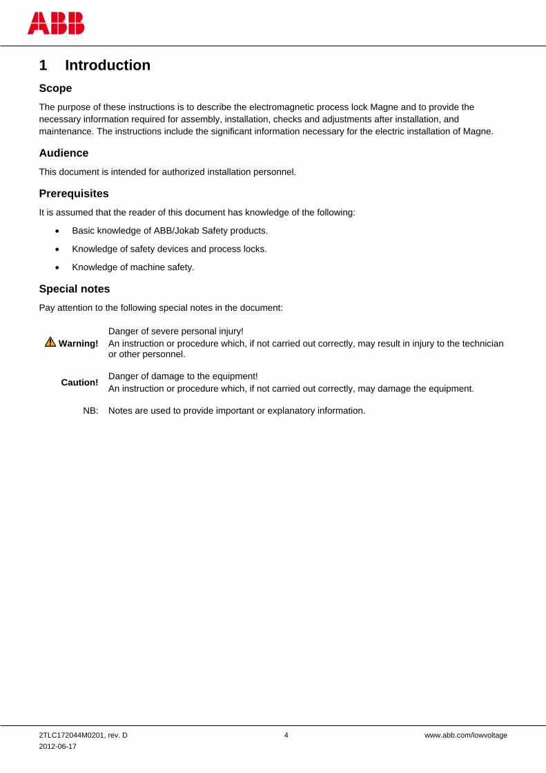
1 Introduction Scope The purpose of these instructions is to describe the electromagnetic process lock Magne and to provide the necessary information required for assembly, installation, checks and adjustments after installation, and maintenance. The instructions include the significant information necessary for the electric installation of Magne.
Audience This document is intended for authorized installation personnel.
Prerequisites It is assumed that the reader of this document has knowledge of the following:
• Basic knowledge of ABB/Jokab Safety products.
• Knowledge of safety devices and process locks.
• Knowledge of machine safety.
Special notes Pay attention to the following special notes in the document:
Warning! Danger of severe personal injury! An instruction or procedure which, if not carried out correctly, may result in injury to the technician or other personnel.
Caution! Danger of damage to the equipment! An instruction or procedure which, if not carried out correctly, may damage the equipment.
NB: Notes are used to provide important or explanatory information.
2TLC172044M0201, rev. D 5 www.abb.com/lowvoltage 2012-06-17
2 Overview General description Magne is an electromagnetic process lock designed without any moving parts, making it durable and well suited for use in industrial applications and other harsh environments. Magne can lock a door or hatch with a holding force of up to 1500 N. When power is turned off, no magnetic material will stick on the surface of the magnet.
Magne 1A is an electromagnetic lock suited for use with any external interlock switch, if required.
Magne 2A and -2Ax are electromagnetic locks equipped with a built-in Eden sensor for guard interlocking. Magne 2A has an 8-pole M12-connector, allowing information outputs for indication signals (e.g. anchor plate locked to magnet). Magne 2Ax has a 5-pole M12-connector with pin configuration enabling connection to a Urax adaptation device for connection to the AS-i bus.
Magne 1B, 2B and 2Bx are identical to above respectively mentioned models except for a permanent magnet built into the anchor plate, which will hold the door or hatch closed with approximately 30 N of force when no power is supplied to the electromagnet. For further details see chapter Model overview.
Y-connections can be used to connect several Magne units and Eden sensors in series, enabling control and monitoring by a single Pluto safety-PLC or Vital safety module. No current peaks above rated current consumption occur at lock activation, simplifying system dimensioning.
Safety regulations
Warning!
Carefully read through this entire manual before using the device.
The devices shall be installed by a trained electrician following the Safety regulations, standards and the Machine directive.
Failure to comply with instructions, operation that is not in accordance with the use prescribed in these instructions, improper installation or handling of the device can affect the safety of people and the plant.
For installation and prescribed use of the product, the special notes in the instructions must be carefully observed and the technical standards relevant to the application must be considered.
In case of failure to comply with the instructions or standards, especially when tampering with and/or modifying the product, any liability is excluded.
2TLC172044M0201, rev. D 6 www.abb.com/lowvoltage 2012-06-17
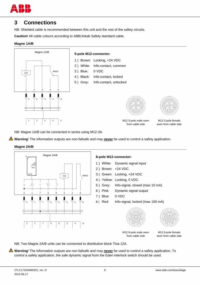
3 Connections NB: Shielded cable is recommended between this unit and the rest of the safety circuits.
Caution! All cable colours according to ABB/Jokab Safety standard cable.
Magne 1A/B
NB: Magne 1A/B can be connected in series using M12-3A.
Warning! The information outputs are non-failsafe and may never be used to control a safety application.
Magne 2A/B
NB: Two Magne 2A/B units can be connected to distribution block Tina 12A.
Warning! The information outputs are non-failsafe and may never be used to control a safety application. To control a safety application, the safe dynamic signal from the Eden interlock switch should be used.
1 2 3 4 5
1 2 3 4 5
1 2 3 4 5
Magne 1A/B
CoilREED
M12 5-pole male seen from cable side
M12 5-pole female seen from cable side
5-pole M12-connector:
1 ) Brown: Locking, +24 VDC 2 ) White: Info-contact, common 3 ) Blue: 0 VDC 4 ) Black: Info-contact, locked 5 ) Grey: Info-contact, unlocked
ADAM
EDEN
12 7 6 5 3 4 8
12 7 6 5 3 4 8
12 7 6 5 3 4 8
Magne 2A/B
Coil REED
8-pole M12-connector:
1 ) White: Dynamic signal input 2 ) Brown: +24 VDC 3 ) Green: Locking, +24 VDC 4 ) Yellow: Locking, 0 VDC 5 ) Grey: Info-signal, closed (max 10 mA) 6 ) Pink: Dynamic signal output 7 ) Blue: 0 VDC 8 ) Red: Info-signal, locked (max 100 mA)
M12 8-pole male seen from cable side
M12 8-pole female seen from cable side
2TLC172044M0201, rev. D 7 www.abb.com/lowvoltage 2012-06-17
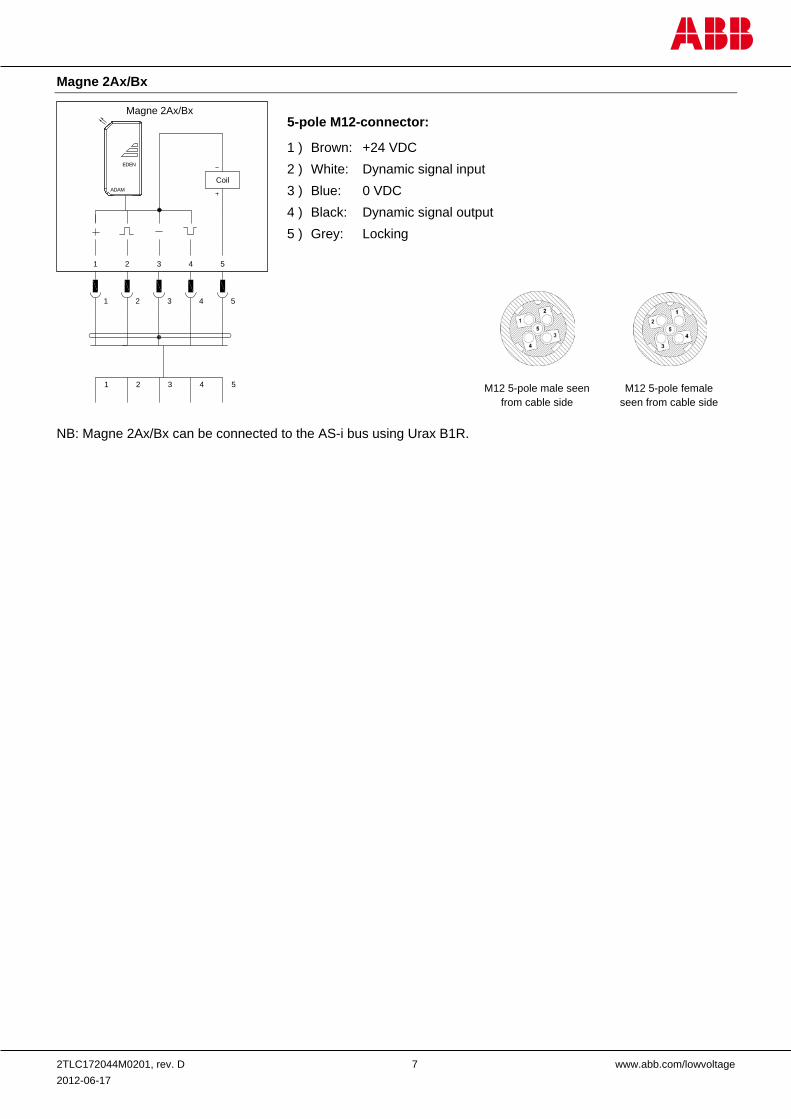
Magne 2Ax/Bx
NB: Magne 2Ax/Bx can be connected to the AS-i bus using Urax B1R.
ADAM
EDEN
21 3 4 5
21 3 4 5
21 3 4 5
Magne 2Ax/Bx
Coil
5-pole M12-connector:
1 ) Brown: +24 VDC 2 ) White: Dynamic signal input 3 ) Blue: 0 VDC 4 ) Black: Dynamic signal output 5 ) Grey: Locking
M12 5-pole male seen from cable side
M12 5-pole female seen from cable side
2TLC172044M0201, rev. D 8 www.abb.com/lowvoltage 2012-06-17
4 Installation and maintenance
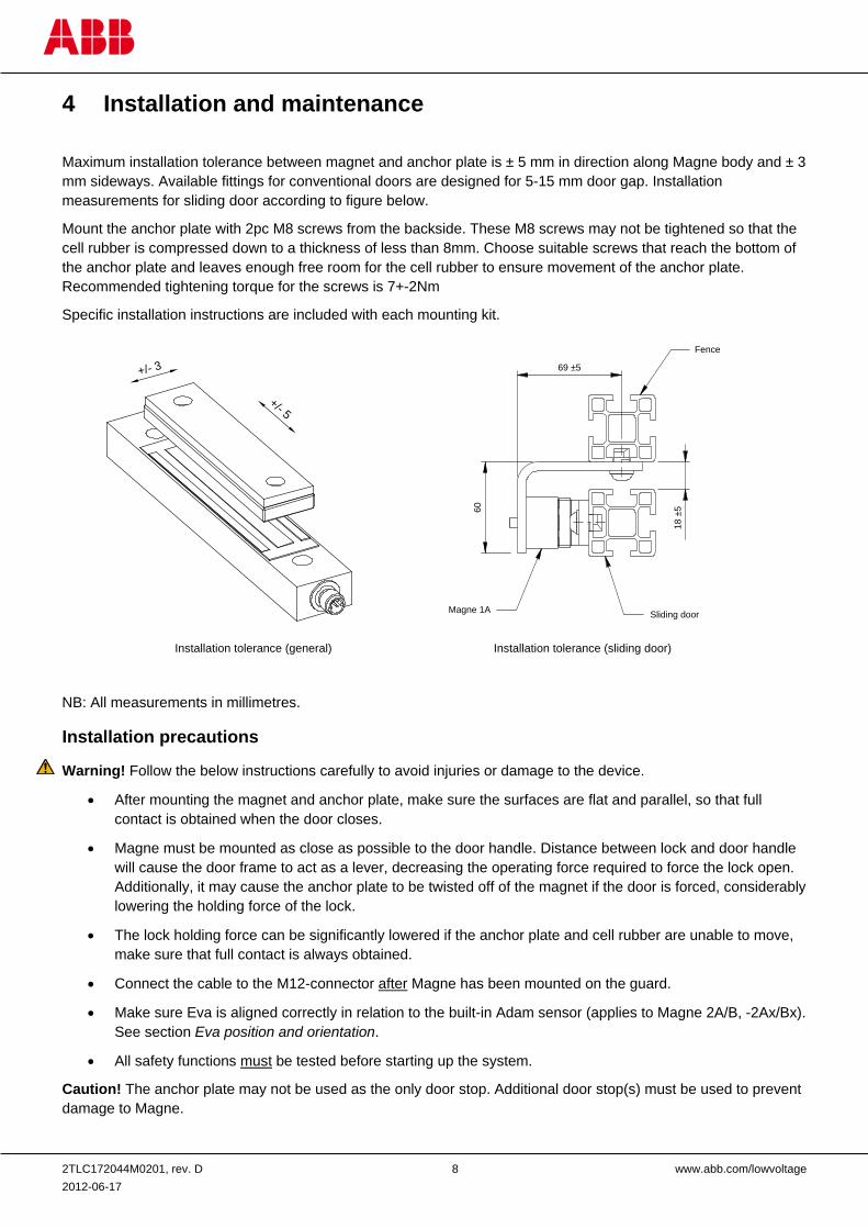
Maximum installation tolerance between magnet and anchor plate is ± 5 mm in direction along Magne body and ± 3 mm sideways. Available fittings for conventional doors are designed for 5-15 mm door gap. Installation measurements for sliding door according to figure below.
Mount the anchor plate with 2pc M8 screws from the backside. These M8 screws may not be tightened so that the cell rubber is compressed down to a thickness of less than 8mm. Choose suitable screws that reach the bottom of the anchor plate and leaves enough free room for the cell rubber to ensure movement of the anchor plate. Recommended tightening torque for the screws is 7+-2Nm
Specific installation instructions are included with each mounting kit.
NB: All measurements in millimetres.
Installation precautions
Warning! Follow the below instructions carefully to avoid injuries or damage to the device.
• After mounting the magnet and anchor plate, make sure the surfaces are flat and parallel, so that full contact is obtained when the door closes.
• Magne must be mounted as close as possible to the door handle. Distance between lock and door handle will cause the door frame to act as a lever, decreasing the operating force required to force the lock open. Additionally, it may cause the anchor plate to be twisted off of the magnet if the door is forced, considerably lowering the holding force of the lock.
• The lock holding force can be significantly lowered if the anchor plate and cell rubber are unable to move, make sure that full contact is always obtained.
• Connect the cable to the M12-connector after Magne has been mounted on the guard.
• Make sure Eva is aligned correctly in relation to the built-in Adam sensor (applies to Magne 2A/B, -2Ax/Bx). See section Eva position and orientation.
• All safety functions must be tested before starting up the system.
Caution! The anchor plate may not be used as the only door stop. Additional door stop(s) must be used to prevent damage to Magne.
60
18±5
69 ±5
Magne 1A Sliding door
Fence
Installation tolerance (general) Installation tolerance (sliding door)
+/- 5
+/- 3
2TLC172044M0201, rev. D 9 www.abb.com/lowvoltage 2012-06-17
Maintenance The Magnet should be cleaned regularly to maintain full holding force.
Warning!
The safety functions and the mechanics shall be tested regularly, at least once every year to confirm that all the safety functions are working properly (EN 62061:2005).
In case of breakdown or damage to the product, contact the nearest ABB/Jokab Safety Service Office or reseller. Do not try to repair the product yourself since it may accidentally cause permanent damage to the product, impairing the safety of the device which in turn could lead to serious injury to personnel.
Eva position and orientation This section applies to Magne 2A/B, -2Ax/Bx only.
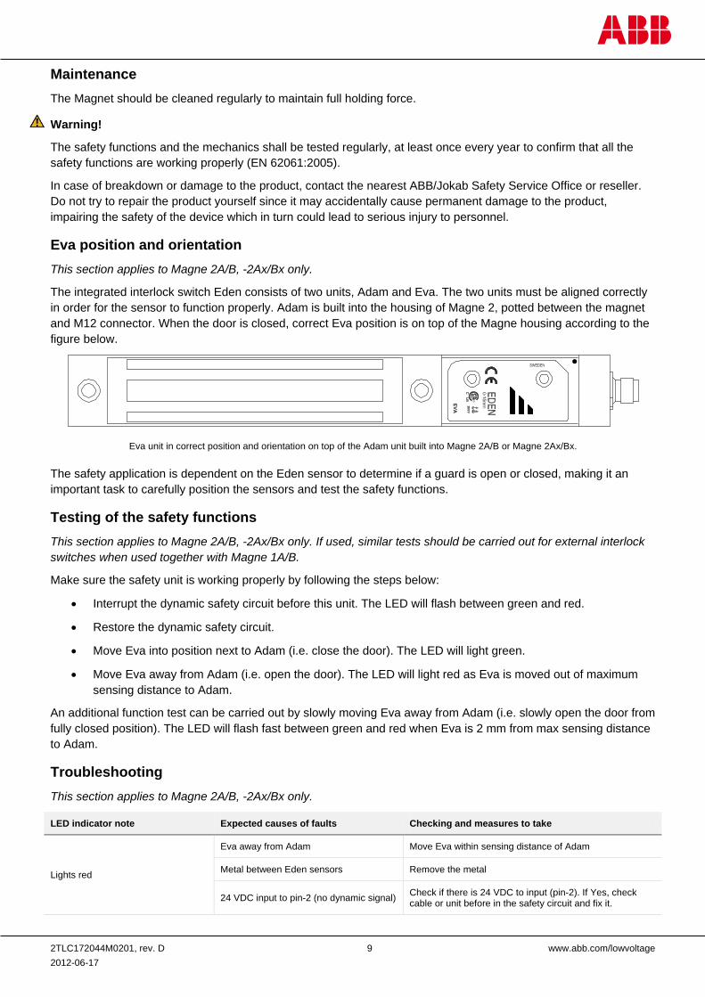
The integrated interlock switch Eden consists of two units, Adam and Eva. The two units must be aligned correctly in order for the sensor to function properly. Adam is built into the housing of Magne 2, potted between the magnet and M12 connector. When the door is closed, correct Eva position is on top of the Magne housing according to the figure below.
The safety application is dependent on the Eden sensor to determine if a guard is open or closed, making it an important task to carefully position the sensors and test the safety functions.
Testing of the safety functions This section applies to Magne 2A/B, -2Ax/Bx only. If used, similar tests should be carried out for external interlock switches when used together with Magne 1A/B.
Make sure the safety unit is working properly by following the steps below:
• Interrupt the dynamic safety circuit before this unit. The LED will flash between green and red.
• Restore the dynamic safety circuit.
• Move Eva into position next to Adam (i.e. close the door). The LED will light green.
• Move Eva away from Adam (i.e. open the door). The LED will light red as Eva is moved out of maximum sensing distance to Adam.
An additional function test can be carried out by slowly moving Eva away from Adam (i.e. slowly open the door from fully closed position). The LED will flash fast between green and red when Eva is 2 mm from max sensing distance to Adam.
Troubleshooting This section applies to Magne 2A/B, -2Ax/Bx only.
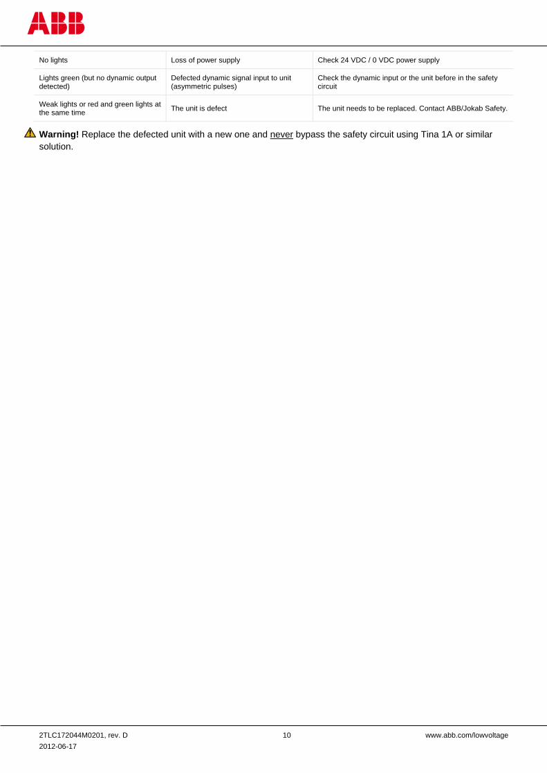
LED indicator note Expected causes of faults Checking and measures to take
Lights red
Eva away from Adam Move Eva within sensing distance of Adam
Metal between Eden sensors Remove the metal
24 VDC input to pin-2 (no dynamic signal) Check if there is 24 VDC to input (pin-2). If Yes, check cable or unit before in the safety circuit and fix it.
Eva unit in correct position and orientation on top of the Adam unit built into Magne 2A/B or Magne 2Ax/Bx.
2TLC172044M0201, rev. D 10 www.abb.com/lowvoltage 2012-06-17
No lights Loss of power supply Check 24 VDC / 0 VDC power supply
Lights green (but no dynamic output detected)
Defected dynamic signal input to unit (asymmetric pulses)
Check the dynamic input or the unit before in the safety circuit
Weak lights or red and green lights at the same time The unit is defect The unit needs to be replaced. Contact ABB/Jokab Safety.
Warning! Replace the defected unit with a new one and never bypass the safety circuit using Tina 1A or similar solution.
2TLC172044M0201, rev. D 11 www.abb.com/lowvoltage 2012-06-17
5 Operation Locking:
1. Close the door. 2. Locking according to PLC program (e.g. by signal from push button).
Unlocking: 1. Unlocking according to PLC program (e.g. by signal from push button, or automatically when the
machine/process cycle has finished as intended). 2. Open the door.
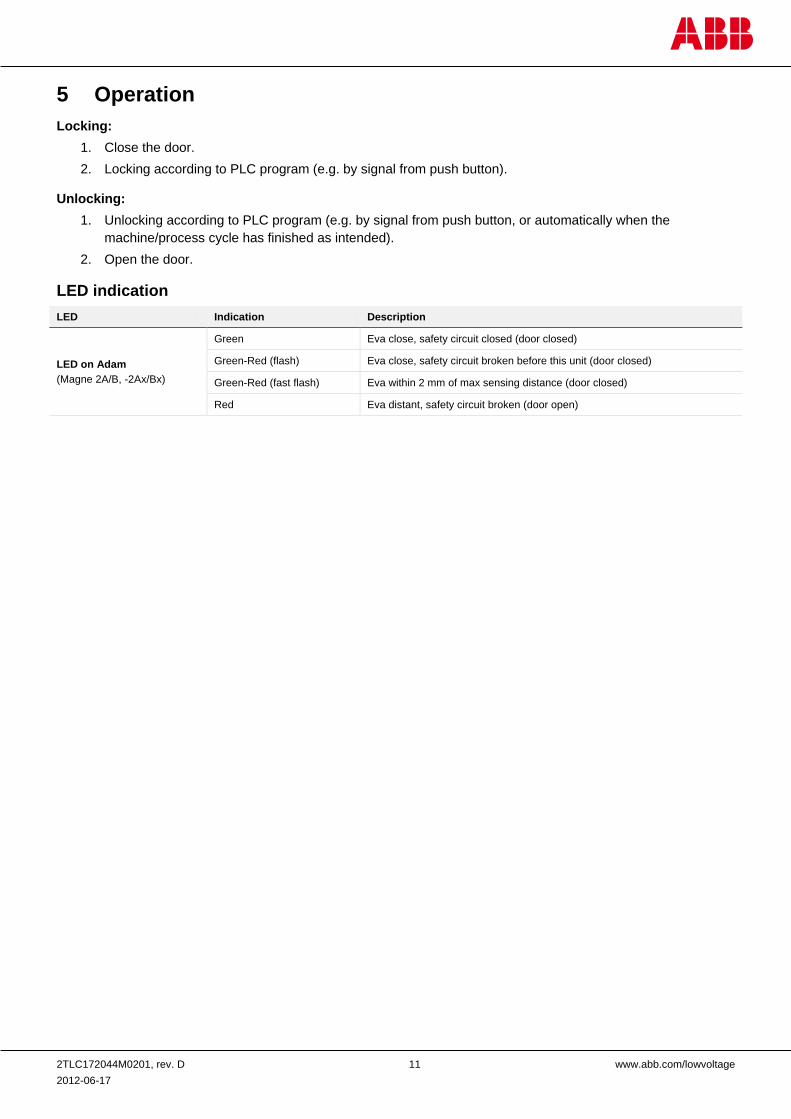
LED indication LED Indication Description
LED on Adam (Magne 2A/B, -2Ax/Bx)
Green Eva close, safety circuit closed (door closed)
Green-Red (flash) Eva close, safety circuit broken before this unit (door closed)
Green-Red (fast flash) Eva within 2 mm of max sensing distance (door closed)
Red Eva distant, safety circuit broken (door open)
2TLC172044M0201, rev. D 12 www.abb.com/lowvoltage 2012-06-17
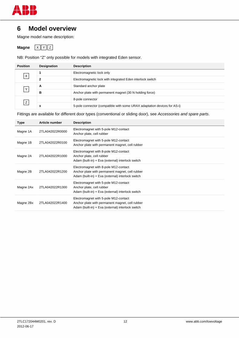
6 Model overview Magne model name description:
Magne
NB: Position “Z” only possible for models with integrated Eden sensor.
Position Designation Description
1 Electromagnetic lock only
2 Electromagnetic lock with integrated Eden interlock switch
A Standard anchor plate
B Anchor plate with permanent magnet (30 N holding force)
8-pole connector
x 5-pole connector (compatible with some URAX adaptation devices for AS-i)
Fittings are available for different door types (conventional or sliding door), see Accessories and spare parts.
Type Article number Description
Magne 1A 2TLA042022R0000 Electromagnet with 5-pole M12-contact Anchor plate, cell rubber
Magne 1B 2TLA042022R0100 Electromagnet with 5-pole M12-contact Anchor plate with permanent magnet, cell rubber
Magne 2A 2TLA042022R1000 Electromagnet with 8-pole M12-contact Anchor plate, cell rubber Adam (built-in) + Eva (external) interlock switch
Magne 2B 2TLA042022R1200 Electromagnet with 8-pole M12-contact Anchor plate with permanent magnet, cell rubber Adam (built-in) + Eva (external) interlock switch
Magne 2Ax 2TLA042022R1300 Electromagnet with 5-pole M12-contact Anchor plate, cell rubber Adam (built-in) + Eva (external) interlock switch
Magne 2Bx 2TLA042022R1400 Electromagnet with 5-pole M12-contact Anchor plate with permanent magnet, cell rubber Adam (built-in) + Eva (external) interlock switch
X Y Z
X
Y
Z
2TLC172044M0201, rev. D 13 www.abb.com/lowvoltage 2012-06-17
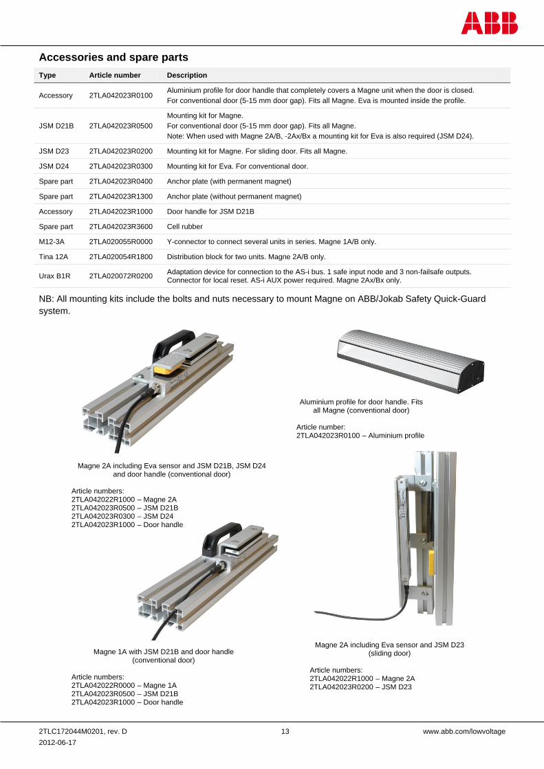
Accessories and spare parts Type Article number Description
Accessory 2TLA042023R0100 Aluminium profile for door handle that completely covers a Magne unit when the door is closed. For conventional door (5-15 mm door gap). Fits all Magne. Eva is mounted inside the profile.
JSM D21B 2TLA042023R0500 Mounting kit for Magne. For conventional door (5-15 mm door gap). Fits all Magne. Note: When used with Magne 2A/B, -2Ax/Bx a mounting kit for Eva is also required (JSM D24).
JSM D23 2TLA042023R0200 Mounting kit for Magne. For sliding door. Fits all Magne.
JSM D24 2TLA042023R0300 Mounting kit for Eva. For conventional door.
Spare part 2TLA042023R0400 Anchor plate (with permanent magnet)
Spare part 2TLA042023R1300 Anchor plate (without permanent magnet)
Accessory 2TLA042023R1000 Door handle for JSM D21B
Spare part 2TLA042023R3600 Cell rubber
M12-3A 2TLA020055R0000 Y-connector to connect several units in series. Magne 1A/B only.
Tina 12A 2TLA020054R1800 Distribution block for two units. Magne 2A/B only.
Urax B1R 2TLA020072R0200 Adaptation device for connection to the AS-i bus. 1 safe input node and 3 non-failsafe outputs. Connector for local reset. AS-i AUX power required. Magne 2Ax/Bx only.
NB: All mounting kits include the bolts and nuts necessary to mount Magne on ABB/Jokab Safety Quick-Guard system.
Magne 2A including Eva sensor and JSM D21B, JSM D24 and door handle (conventional door)
Article numbers: 2TLA042022R1000 – Magne 2A 2TLA042023R0500 – JSM D21B 2TLA042023R0300 – JSM D24 2TLA042023R1000 – Door handle
Aluminium profile for door handle. Fits all Magne (conventional door)
Article number: 2TLA042023R0100 – Aluminium profile
Magne 1A with JSM D21B and door handle (conventional door)
Article numbers: 2TLA042022R0000 – Magne 1A 2TLA042023R0500 – JSM D21B 2TLA042023R1000 – Door handle
Magne 2A including Eva sensor and JSM D23 (sliding door)
Article numbers: 2TLA042022R1000 – Magne 2A 2TLA042023R0200 – JSM D23
2TLC172044M0201, rev. D 14 www.abb.com/lowvoltage 2012-06-17
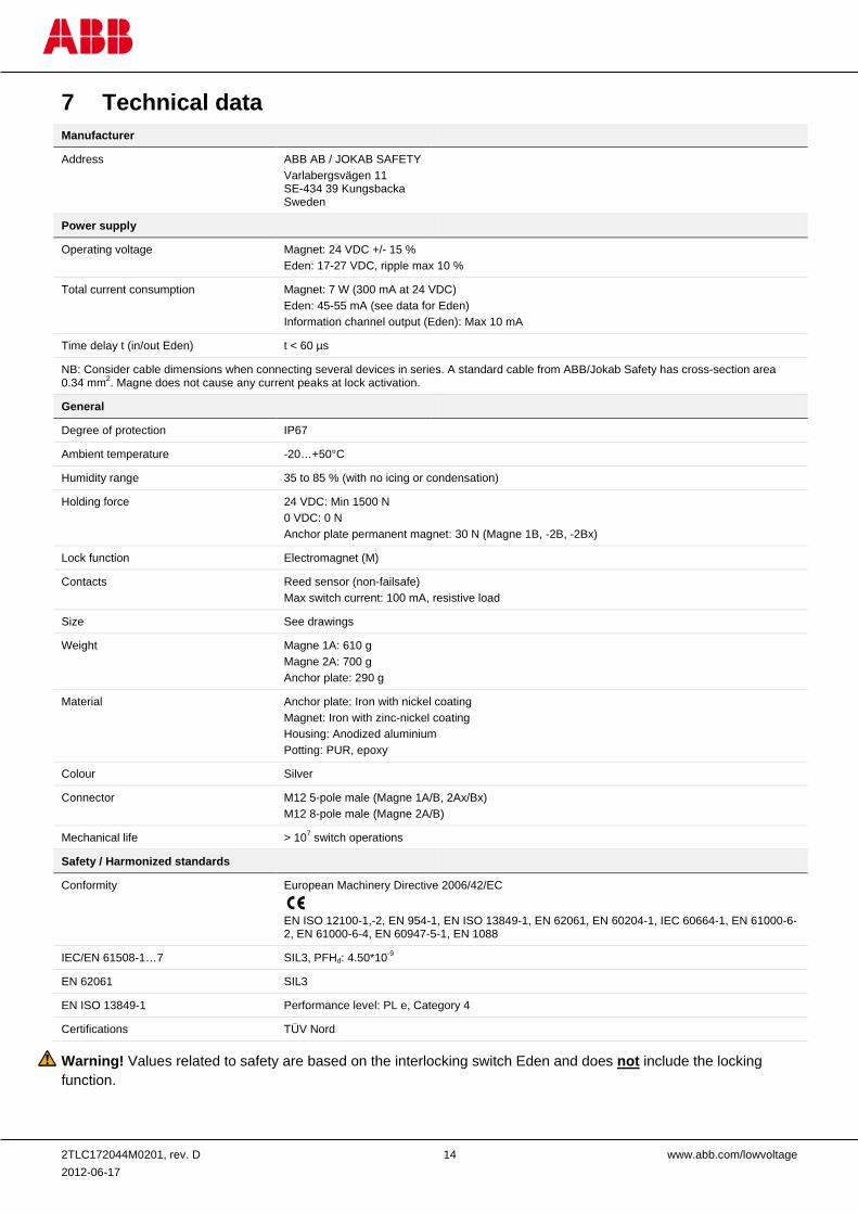
7 Technical data Manufacturer
Address ABB AB / JOKAB SAFETY Varlabergsvägen 11 SE-434 39 Kungsbacka Sweden
Power supply
Operating voltage Magnet: 24 VDC +/- 15 % Eden: 17-27 VDC, ripple max 10 %
Total current consumption Magnet: 7 W (300 mA at 24 VDC) Eden: 45-55 mA (see data for Eden) Information channel output (Eden): Max 10 mA
Time delay t (in/out Eden) t < 60 µs
NB: Consider cable dimensions when connecting several devices in series. A standard cable from ABB/Jokab Safety has cross-section area 0.34 mm2. Magne does not cause any current peaks at lock activation.
General
Degree of protection IP67
Ambient temperature -20…+50°C
Humidity range 35 to 85 % (with no icing or condensation)
Holding force 24 VDC: Min 1500 N 0 VDC: 0 N Anchor plate permanent magnet: 30 N (Magne 1B, -2B, -2Bx)
Lock function Electromagnet (M)
Contacts Reed sensor (non-failsafe) Max switch current: 100 mA, resistive load
Size See drawings
Weight Magne 1A: 610 g Magne 2A: 700 g Anchor plate: 290 g
Material Anchor plate: Iron with nickel coating Magnet: Iron with zinc-nickel coating Housing: Anodized aluminium Potting: PUR, epoxy
Colour Silver
Connector M12 5-pole male (Magne 1A/B, 2Ax/Bx) M12 8-pole male (Magne 2A/B)
Mechanical life > 107 switch operations
Safety / Harmonized standards
Conformity European Machinery Directive 2006/42/EC
EN ISO 12100-1,-2, EN 954-1, EN ISO 13849-1, EN 62061, EN 60204-1, IEC 60664-1, EN 61000-6-2, EN 61000-6-4, EN 60947-5-1, EN 1088
IEC/EN 61508-1…7 SIL3, PFHd: 4.50*10-9
EN 62061 SIL3
EN ISO 13849-1 Performance level: PL e, Category 4
Certifications TÜV Nord
Warning! Values related to safety are based on the interlocking switch Eden and does not include the locking function.
2TLC172044M0201, rev. D 15 www.abb.com/lowvoltage 2012-06-17
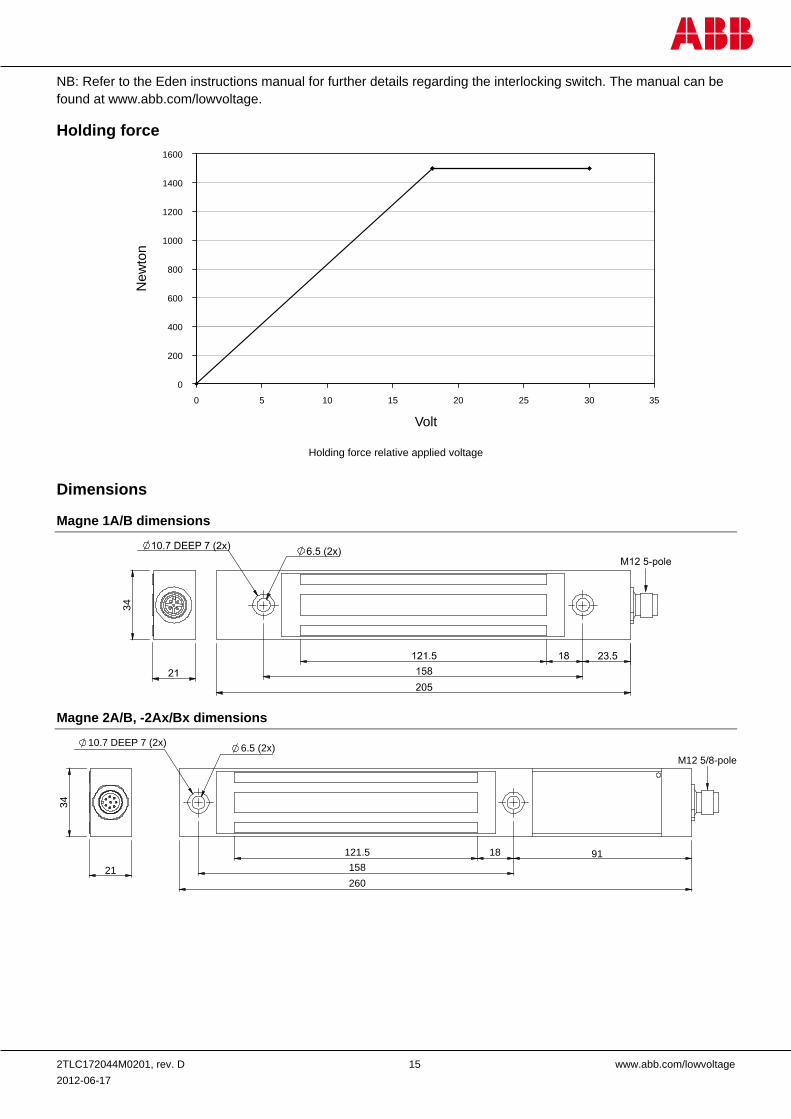
NB: Refer to the Eden instructions manual for further details regarding the interlocking switch. The manual can be found at www.abb.com/lowvoltage.
Holding force
Dimensions
Magne 1A/B dimensions
Magne 2A/B, -2Ax/Bx dimensions
0
200
400
600
800
1000
1200
1400
1600
0 5 10 15 20 25 30 35
Volt
New
ton
34
10.7 DEEP 7 (2x) 6.5 (2x)
34
21
M12 5/8-pole
91
260158
121.5 18
Holding force relative applied voltage
2TLC172044M0201, rev. D 16 www.abb.com/lowvoltage 2012-06-17
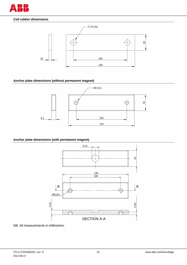
Cell rubber dimensions
Anchor plate dimensions (without permanent magnet)
Anchor plate dimensions (with permanent magnet)
NB: All measurements in millimetres.
10 100
128
10 (2x)
30
9,1
M8 (2x)
100
130
32
130100
M8(2x)
AA
14
SECTION A-A
9,10
5,50
32
2TLC172044M0201, rev. D 17 www.abb.com/lowvoltage 2012-06-17
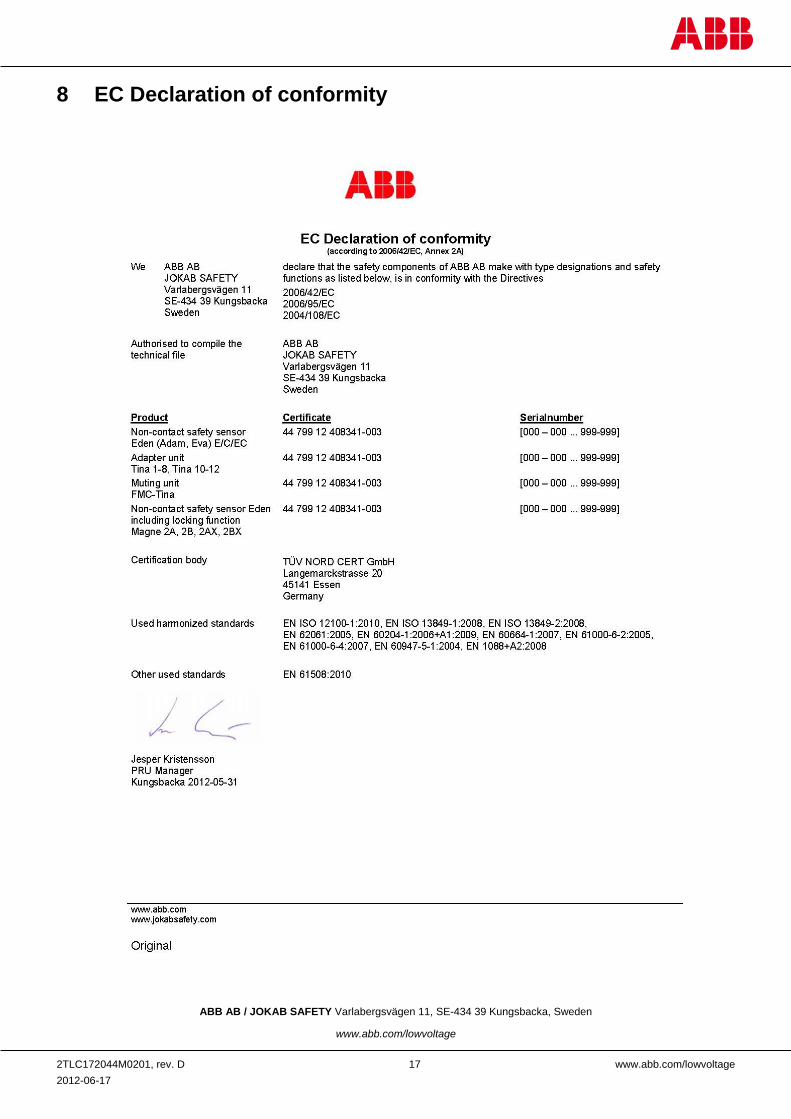
8 EC Declaration of conformity
ABB AB / JOKAB SAFETY Varlabergsvägen 11, SE-434 39 Kungsbacka, Sweden
www.abb.com/lowvoltage