Embed Size (px)
Citation preview

The essentials of imaging
www.minolta-qms.com
magicolor® 3100 Series
1750051-001B
Service Manual

ii

Introduction


Introduction
v
1. TrademarksThe following are trademarks or registered trademarks of their respective owners. Other product names mentioned in this manual may also be trademarks or registered trademarks of their respective owners. Registered trademarks are registered in the United States Patent and Trademark Office; some trademarks may also be registered in other countries. QMS, magicolor, and the MINOLTA-QMS logo are registered trademarks of MINOLTA-QMS, Inc. Minolta is a trade-mark of Minolta Co., Ltd.
2. Copyright NoticeThis manual is Copyrighted © 2001 by MINOLTA-QMS, Inc., One Magnum Pass, Mobile, AL 36618. All Rights Reserved. This manual may not be copied in whole or in part, nor transferred to any other media or language, without the express written permission of MINOLTA-QMS, Inc.
Cautions for operation
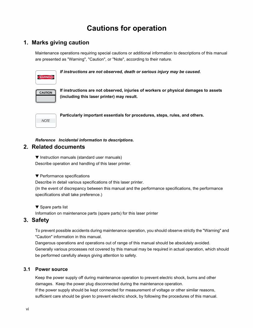
1. Marks giving cautionMaintenance operations requiring special cautions or additional information to descriptions of this manual are presented as "Warning", "Caution", or "Note", according to their nature.
If instructions are not observed, death or serious injury may be caused.
If instructions are not observed, injuries of workers or physical damages to assets (including this laser printer) may result.
Particularly important essentials for procedures, steps, rules, and others.
Reference Incidental information to descriptions.
2. Related documents Instruction manuals (standard user manuals)Describe operation and handling of this laser printer.
Performance specificationsDescribe in detail various specifications of this laser printer.(In the event of discrepancy between this manual and the performance specifications, the performance specifications shall take preference.)
Spare parts listInformation on maintenance parts (spare parts) for this laser printer
3. SafetyTo prevent possible accidents during maintenance operation, you should observe strictly the "Warning" and "Caution" information in this manual.Dangerous operations and operations out of range of this manual should be absolutely avoided.Generally various processes not covered by this manual may be required in actual operation, which should be performed carefully always giving attention to safety.
3.1 Power sourceKeep the power supply off during maintenance operation to prevent electric shock, burns and other damages. Keep the power plug disconnected during the maintenance operation.If the power supply should be kept connected for measurement of voltage or other similar reasons, sufficient care should be given to prevent electric shock, by following the procedures of this manual.
vi
Introduction
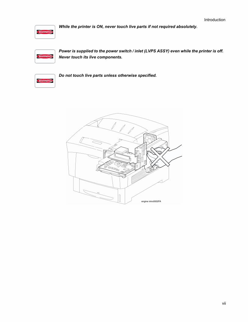
While the printer is ON, never touch live parts if not required absolutely.Power is supplied to the power switch / inlet (LVPS ASSY) even while the printer is off. Never touch its live components.
Do not touch live parts unless otherwise specified.
vii
3.2 Driving unitsWhen servicing gears or other driving units, be sure to turn them OFF and plug off. Drive them manually when required.
Never touch the gears or other driving units while the printer is running.
3.3 High-temperature unitsWhen servicing high-temperature units (securing unit, etc.), be sure to turn them OFF to prevent burns, injuries and other troubles, remove the power plug and start service processes after they have cooled down enough.
Immediately after completion of operation, they are still hot. Start services after more than 40 minutes.
3.4 Laser beams
•If your eyes are exposed to laser beams, you may lose your eyesight.•Never open the cover if warning label for laser beams is attached there.•Before disassembling and reassembling this laser printer, be sure to turn it OFF.•When servicing this laser printer while it is running, be sure to follow theprocedures specified in this manual.•You should understand the features of the laser beams which are capable ofhaving an injurious action on the human body, not to extend the danger over theworkers as well as other people around the printer.
Laser beams have features as follows:•Frequencies are smaller in width than other beams (sun and electric bulbs) andphases are uniform so that high monochromatic and convergence performancecan be obtained and thin beams of light can reach places at a long distance.•Due to the high convergence, beams are concentrated in high density and hightemperature, which is dangerous to human body.
Reference: Laser beams of this laser printer is invisible rays which you cannot see.
viii
Introduction
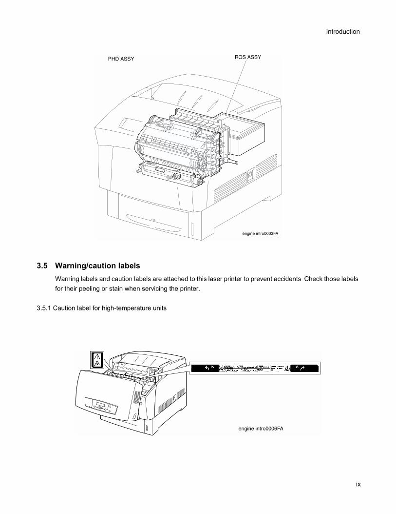
3.5 Warning/caution labelsWarning labels and caution labels are attached to this laser printer to prevent accidents Check those labels for their peeling or stain when servicing the printer.
3.5.1 Caution label for high-temperature units
ix
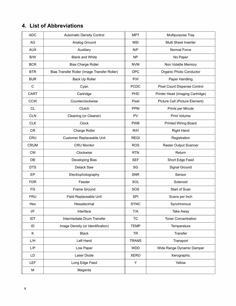
4. List of AbbreviationsADC Automatic Density Control MPT Multipurpose Tray
AG Analog Ground MSI Multi Sheet Inserter
AUX Auxiliary N/F Normal Force
B/W Blank and White NP No Paper
BCR Bias Charge Roller NVM Non Volatile Memory
BTR Bias Transfer Roller (Image Transfer Roller) OPC Organic Photo Conductor
BUR Back Up Roller P/H Paper Handling
C Cyan PCDC Pixel Count Dispense Control
CART Cartridge PHD Printer Head (Imaging Cartridge)
CCW Counterclockwise Pixel Picture Cell (Picture Element)
CL Clutch PPM Prints per Minute
CLN Cleaning (or Cleaner) PV Print Volume
CLK Clock PWB Printed Wiring Board
CR Charge Roller R/H Right Hand
CRU Customer Replaceable Unit REGI Registration
CRUM CRU Monitor ROS Raster Output Scanner
CW Clockwise RTN Return
DB Developing Bias SEF Short Edge Feed
DTS Detack Saw SG Signal Ground
EP Electrophotography SNR Sensor
FDR Feeder SOL Solenoid
FG Frame Ground SOS Start of Scan
FRU Field Replaceable Unit SPI Scans per Inch
Hex Hexadecimal SYNC Synchronous
I/F Interface T/A Take Away
IDT Intermediate Drum Transfer TC Toner Concentration
ID Image Density (or Identification) TEMP Temperature
K Black TR Transfer
L/H Left Hand TRANS Transport
L/P Low Paper WDD Wide Range Dynamic Damper
LD Laser Diode XERO Xerographic
LEF Long Edge Feed Y Yellow
M Magenta
x
Introduction
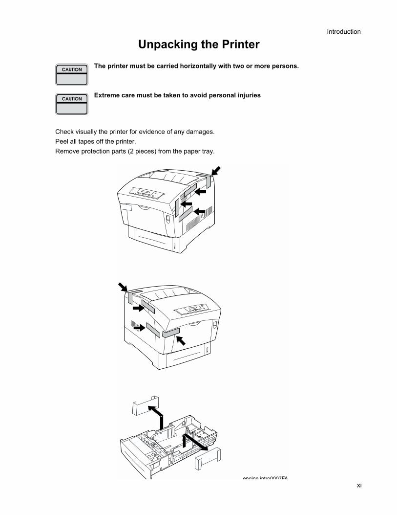
Unpacking the PrinterThe printer must be carried horizontally with two or more persons.
Extreme care must be taken to avoid personal injuries
Check visually the printer for evidence of any damages.Peel all tapes off the printer.Remove protection parts (2 pieces) from the paper tray.
xi

xii

Contents

CONTENTS
Introduction ..................................................................................................... iii1. Trademarks ...................................................................................................................... v2. Copyright Notice............................................................................................................... v1. Marks giving caution........................................................................................................ vi2. Related documents.......................................................................................................... vi3. Safety .............................................................................................................................. vi
3.1 Power source .........................................................................................................................................vi3.2 Driving units ......................................................................................................................................... viii3.3 High-temperature units ........................................................................................................................ viii3.4 Laser beams ........................................................................................................................................ viii3.5 Warning/caution labels...........................................................................................................................ix
4. List of Abbreviations ......................................................................................................... x
Contents........................................................................................................ 13
Chapter 1 Troubleshooting ........................................................................ 1-231. Progressing with the Troubleshooting .........................................................................1-25
1.1 Flow of Troubleshooting.................................................................................................................... 1-251.2 Preparatory Requirements................................................................................................................ 1-261.3 Cautions for Service Operations ....................................................................................................... 1-271.4 Cautions for FIP Use......................................................................................................................... 1-28
2. Level 1 FIP ..................................................................................................................1-302.1 Level 1 FIP........................................................................................................................................ 1-302.2 Flow of Level 1 FIP ........................................................................................................................... 1-30
3. Level 2 FIP ..................................................................................................................1-313.1 Level 2 FIP........................................................................................................................................ 1-313.2 Error / Status Code List..................................................................................................................... 1-313.3 Operating / Clearing the Error........................................................................................................... 1-343.4 Error Code FIP.................................................................................................................................. 1-373.5 Image Trouble FIP ............................................................................................................................ 1-813.6 Roller Circumferences ...................................................................................................................... 1-813.7 Other FIPs......................................................................................................................................... 1-92
4. Preventive Maintenance..............................................................................................1-94
Chapter 2 Operation of Diagnostics........................................................... 2-951. Diagnostics for a Standalone Printer ...........................................................................2-97
1.1 General ............................................................................................................................................. 2-971.2 Printing Method................................................................................................................................. 2-97
1.3 Test Print Pattern .............................................................................................................................. 2-982. Diagnostics Using the MINOLTA- QMS magicolor 3100 Diagnostics (Hanabi Service Commander) .........................................................................................2-99
2.1 General ............................................................................................................................................. 2-992.2 Preparation ..................................................................................................................................... 2-1002.3 Operation of magicolor 3100 Diagnostics ....................................................................................... 2-1012.4 Test Print......................................................................................................................................... 2-1032.5 Input Test ........................................................................................................................................ 2-1042.6 Output Test ..................................................................................................................................... 2-1072.7 Operation of EEPROM.................................................................................................................... 2-110
Chapter 3 Removal and Replacement Procedures ................................. 3-1191. Removal and Replacement Procedures....................................................................3-121
1.1 Before starting service work............................................................................................................ 3-1211.2 Description of procedures ............................................................................................................... 3-122
RRP1. COVERS............................................................................................................3-123RRP1.1 CONSOLE PANEL HANABI (PL1.1.1).................................................................................... 3-123RRP1.2 COVER ASSY FRONT HEAD (PL1.1.2)................................................................................. 3-124RRP1.3 FAN FUSER (PL1.1.7) ............................................................................................................ 3-126RRP1.4 COVER TOP MAIN (PL1.1.9) ................................................................................................. 3-128RRP1.5 COVER ASSY TOP PHD (PL1.1.10) ...................................................................................... 3-129RRP1.6 COVER REAR (PL1.1.20)....................................................................................................... 3-130RRP1.7 LINK:L (PL1.1.23).................................................................................................................... 3-131RRP1.8 LINK:R (PL1.1.23) ................................................................................................................... 3-132RRP1.9 COVER SIDE R (PL1.1.24)..................................................................................................... 3-133RRP1.10 COVER ASSY FRONT IN (PL1.1.25) ................................................................................... 3-134RRP1.11 COVER MSI (PL1.1.26) ........................................................................................................ 3-136RRP1.12 TRAY ASSY MSI (PL1.1.28) ................................................................................................. 3-137RRP1.13 COVER ASSY FRONT (PL1.1.29)........................................................................................ 3-138RRP1.14 COVER SIDE L (PL1.1.30) ................................................................................................... 3-140
RRP2. PAPER CASSETTE...........................................................................................3-141RRP2.1 ROLL ASSY (PL2.1.1)............................................................................................................. 3-141RRP2.2 HOLDER RETARD (PL2.1.3).................................................................................................. 3-142RRP2.3 CASSETTE ASSY FRONT (REFERENCE ONLY) ................................................................. 3-144
RRP3. PAPER FEEDER ...............................................................................................3-146RRP3.1 CHUTE ASSY TURN (PL3.1.2)............................................................................................... 3-146RRP3.2 COVER CASSETTE REAR (PL3.1.3)..................................................................................... 3-148RRP3.3 FEEDER ASSY UNIT (REFERENCE ONLY) ......................................................................... 3-150RRP3.4 HOUSING ASSY FEEDER L (REFERENCE ONLY) .............................................................. 3-152RRP3.5 HOUSING ASSY FEEDER R (REFERENCE ONLY) ............................................................. 3-154RRP3.6 SENSOR HUM TEMP (PL3.2.2) ............................................................................................. 3-156RRP3.7 HARNESS ASSY OPFREC (PL3.2.3)..................................................................................... 3-157
16
Table of Contents
RRP3.8 SWITCH ASSY SIZE (PL3.2.4)............................................................................................... 3-158RRP3.9 LEVER LOW PAPER (PL3.2.7) .............................................................................................. 3-160RRP3.10 INDICATOR (PL3.2.8)........................................................................................................... 3-162RRP3.11 GUIDE INDICATOR (PL3.2.10) ............................................................................................ 3-164RRP3.12 PICKUP ASSY (PL3.3.1)....................................................................................................... 3-166RRP3.13 ROLL ASSY FEED (PL3.3.2) ................................................................................................ 3-168RRP3.14 SENSOR PHOTO:NO PAPER (PL3.3.3) .............................................................................. 3-170RRP3.15 SENSOR PHOTO:LOW PAPER (PL3.3.3) ........................................................................... 3-171RRP3.16 ACTUATOR NO PAPER (PL3.3.4) ....................................................................................... 3-172RRP3.17 LINK ACTUATOR (PL3.3.5).................................................................................................. 3-173RRP3.18 SOLENOID FEED (PL3.3.16) ............................................................................................... 3-174RRP3.19 CLUTCH ASSY TURN (PL3.3.17) ........................................................................................ 3-175RRP3.20 ROLL ASSY TURN (PL3.3.19).............................................................................................. 3-176RRP3.21 ROLL ASSY (PL3.3.22)......................................................................................................... 3-177RRP4. HOUSING ASSY RETARD................................................................................3-178RRP4.1 HOUSING ASSY RETARD (PL4.1.1) ..................................................................................... 3-178RRP4.2 ROLL TURN (PL4.1.2) ............................................................................................................ 3-179RRP4.3 ROLL ASSY RETARD (PL4.1.5)............................................................................................. 3-180RRP4.4 CLUTCH TURN (PL4.1.9) ....................................................................................................... 3-182RRP4.5 STUD RTD (PL4.1.10) ............................................................................................................ 3-183
RRP5. FRONT ASSY IN ...............................................................................................3-184RRP5.1 FRONT ASSY IN (PL5.1.1) ..................................................................................................... 3-184RRP5.2 SENSOR ADC ASSY (PL5.1.11) ............................................................................................ 3-187RRP5.3 SENSOR TNR FULL (PL5.1.13) ............................................................................................. 3-188RRP5.4 FUSER DRIVE ASSY (PL5.1.18)............................................................................................ 3-190RRP5.5 LATCH R (PL5.1.21) ............................................................................................................... 3-192RRP5.6 LATCH L (PL5.1.30)................................................................................................................ 3-193
RRP6. CHUTE ASSY OUT ...........................................................................................3-194RRP6.1 CHUTE ASSY OUT (PL6.1.1) ................................................................................................. 3-194RRP6.2 SENSOR PHOTO:FULL STACK (PL6.1.4)............................................................................. 3-197RRP6.3 ACTUATOR FULL (PL6.1.5) ................................................................................................... 3-198RRP6.4 SENSOR PHOTO:DUP (PL6.1.4) ........................................................................................... 3-199RRP6.5 SENSOR PHOTO:MSI (PL6.1.4) ............................................................................................ 3-200RRP6.6 ELIMINATOR ASSY (PL6.1.9) ................................................................................................ 3-201RRP6.7 ROLL DUP (PL6.1.12)............................................................................................................. 3-202RRP6.8 ACTUATOR DUP (PL6.1.13) .................................................................................................. 3-204RRP6.9 LATCH OUT (PL6.1.18) .......................................................................................................... 3-206RRP6.10 ROLL ASSY FEED (PL6.1.27) .............................................................................................. 3-207RRP6.11 ACTUATOR MSI (PL6.1.37) ................................................................................................. 3-208RRP6.12 SOLENOID FEED MSI (PL6.1.40) ........................................................................................ 3-209RRP6.13 SHAFT ASSY ROLL FEED (REFERENCE ONLY)............................................................... 3-210RRP6.14 PLATE ASSY BOTTOM MSI (PL6.1.42)............................................................................... 3-212
RRP7. CHUTE ASSY EXIT...........................................................................................3-213RRP7.1 CHUTE ASSY EXIT (PL7.1.1)................................................................................................. 3-213
17
RRP7.2 ROLL EXIT (PL7.1.4) ............................................................................................................. 3-214RRP7.3 ROLL MID (PL7.1.5)................................................................................................................ 3-215RRP7.4 MOTOR ASSY DUP (PL7.1.8) ................................................................................................ 3-216
RRP8. BTR ASSY & FUSER.........................................................................................3-217RRP8.1 FUSER ASSY (PL8.1.1).......................................................................................................... 3-217RRP8.2 ROLL ASSY EXIT (PL8.1.3).................................................................................................... 3-218RRP8.3 ACTUATOR EXIT (PL8.1.7).................................................................................................... 3-220RRP8.4 BTR UNIT ASSY (PL8.1.12) ................................................................................................... 3-221RRP8.5 STRAP (PL8.1.13)................................................................................................................... 3-222
RRP9. XEROGRAPHICS..............................................................................................3-224RRP9.1 ROS ASSY (PL9.1.1) .............................................................................................................. 3-224RRP9.2 HSG ASSY BIAS (PL9.1.4) ..................................................................................................... 3-226RRP9.3 CHUTE ASSY REGI (PL9.1.6)................................................................................................ 3-228RRP9.4 SENSOR PHOTO:REGI (PL9.1.8).......................................................................................... 3-230RRP9.5 ACTUATOR REGI (PL9.1.9) ................................................................................................... 3-231RRP9.6 OHP SENSOR ASSY (PL9.1.12) ............................................................................................ 3-232
RRP10. TCRU ASSY ....................................................................................................3-236RRP10.1 HOLDER TCRU ASSY UNIT (REFERENCE ONLY) ............................................................ 3-236RRP10.2 HOLDER TCRU ASSY (1) (PL10.1.1)................................................................................... 3-239RRP10.3 HOLDER TCRU ASSY (2) (PL10.1.2)................................................................................... 3-240RRP10.4 HOLDER TCRU ASSY (3) (PL10.1.3)................................................................................... 3-241RRP10.5 HOLDER TCRU ASSY (4) (PL10.1.4)................................................................................... 3-242RRP10.6 SWITCH TCRU ASSY (PL10.1.18)....................................................................................... 3-243RRP10.7 SENSOR TONER LOW (PL10.1.8)....................................................................................... 3-244RRP10.8 PWBA EEPROM STD (PL10.1.16) ....................................................................................... 3-245RRP10.9 S-HVPS (PL10.1.17) ............................................................................................................. 3-246
RRP11. FRAME & DRIVE.............................................................................................3-247RRP11.1 LEVER DRUM:L (PL11.1.4) .................................................................................................. 3-247RRP11.2 LEVER DRUM:R (PL11.1.4) ................................................................................................. 3-250RRP11.3 ACTUATOR I/R (PL11.1.8) ................................................................................................... 3-253RRP11.4 DEVE DRIVE ASSY (PL11.1.13) .......................................................................................... 3-254RRP11.5 MAIN DRIVE ASSY (PL11.1.14) ........................................................................................... 3-255RRP11.6 PWBA ASSY EARTH (PL11.1.16) ........................................................................................ 3-256
RRP12. ELECTRICAL...................................................................................................3-258RRP12.1 PWBA HNB MCU (PL12.1.1) ................................................................................................ 3-258RRP12.2 FAN REAR (PL12.1.2) .......................................................................................................... 3-260RRP12.3 CONTROLLER BOARD (PL12.1.4)(TBD)............................................................................. 3-261RRP12.4 LVPS (PL12.1.10) ................................................................................................................. 3-262RRP12.5 HARNESS ASSY AC SW (PL12.1.11).................................................................................. 3-264RRP12.6 PWBA HNB DRV (PL12.1.12)............................................................................................... 3-265RRP12.7 BOX ASSY MCU/ESS (REFERENCE ONLY) ...................................................................... 3-266RRP12.8 HOUSING ASSY CONTACT (PL12.1.14)............................................................................. 3-268
18
Table of Contents
Chapter 4 Plug/Jack (P/J) Connector Locations ...................................... 4-2711. Connector [P (plug) / J (jack)]....................................................................................4-273
1.1 List of P/J ........................................................................................................................................ 4-2731.2 P/J layout diagram .......................................................................................................................... 4-275
Chapter 5 Parts List ................................................................................. 5-2791. Parts List....................................................................................................................5-281
1.1 Caution for use of parts list ............................................................................................................. 5-281
Chapter 6 Principles of Operation............................................................ 6-3131. Printing Process ........................................................................................................6-315
1.1 Summary of Printing Process ......................................................................................................... 6-3151.2 Schematic Diagram for Printing Processes .................................................................................... 6-3161.3 Description of Printing Process Techniques ................................................................................... 6-317
2. Flow of Print Data......................................................................................................6-3302.1 Data Flow........................................................................................................................................ 6-330
3. Drive Transmission Route .........................................................................................6-3313.1 MAIN DRIVE ASSY ........................................................................................................................ 6-3313.2 DEVE DRIVE ASSY........................................................................................................................ 6-3323.3 HOLDER TCRU ASSY (Y, M, C, K)................................................................................................ 6-3323.4 FUSER DRIVE ASSY ..................................................................................................................... 6-3333.5 MOTOR ASSY DUP ....................................................................................................................... 6-3333.6 Gear • Layout .................................................................................................................................. 6-334
4. Paper Transport.........................................................................................................6-3354.1 Paper Transport Route (without option).......................................................................................... 6-3354.2 Layout of Paper Transport Route.................................................................................................... 6-336
5. Functions of Major Functional Components..............................................................6-3375.1 Paper Cassette ............................................................................................................................... 6-3385.2 Paper Feeder .................................................................................................................................. 6-3405.3 Housing Assy Retard ...................................................................................................................... 6-3425.4 Front Assy In................................................................................................................................... 6-3445.5 Chute Assy Out............................................................................................................................... 6-3465.6 Chute Assy Exit............................................................................................................................... 6-3485.7 BTR Assy & Fuser .......................................................................................................................... 6-3505.8 Xerographics................................................................................................................................... 6-3525.9 TCRU Assy ..................................................................................................................................... 6-3545.10 Frame & Drive............................................................................................................................... 6-3565.11 Electrical ....................................................................................................................................... 6-358
6. MODES .....................................................................................................................6-3606.1 Print Mode....................................................................................................................................... 6-360
19
6.2 Operation Modes ............................................................................................................................ 6-3607. Control .......................................................................................................................6-361
7.1 Control of Paper Size...................................................................................................................... 6-3617.2 Selective Control on Paper Pick-up Unit ......................................................................................... 6-3617.3 ROS Light Quantity Control ............................................................................................................ 6-3617.4 Process Control .............................................................................................................................. 6-3627.5 Color Registration Control............................................................................................................... 6-3657.6 BTR UNIT ASSY Control ................................................................................................................ 6-3667.7 Toner Control .................................................................................................................................. 6-3677.8 Fuser Control .................................................................................................................................. 6-368
Chapter 7 Wiring Diagrams and Signal Information................................. 7-3691. General Wiring Diagram............................................................................................7-3711. Wiring Diagram between Parts.................................................................................7-373
1.1 Configuration................................................................................................................................... 7-3731.2 Notes on Using the Wiring Diagram between Parts........................................................................ 7-375
Chapter 8 Printer Specifications .............................................................. 8-4011. Configuration of Printer..............................................................................................8-403
1.1 Basic Configuration......................................................................................................................... 8-4031.2 Functional Configuration ................................................................................................................. 8-403
2. Electrical Properties...................................................................................................8-4042.1 Power Source ................................................................................................................................. 8-4042.2 Power Consumption........................................................................................................................ 8-404
3. Mechanical Properties ...............................................................................................8-4043.1 Dimensions/Mass of Printer ............................................................................................................ 8-4043.2 Dimensions/Mass of Universal Paper Tray (standard paper supply - 500 sheets) ......................... 8-4053.3 Dimensions/Mass of Consumables (CRU) ..................................................................................... 8-4053.4 Installation Space (min. installation space)..................................................................................... 8-406
4. Functions...................................................................................................................8-4074.1 Recording System........................................................................................................................... 8-4074.2 Exposure System............................................................................................................................ 8-4074.3 Development System...................................................................................................................... 8-4074.4 Fixing System ................................................................................................................................. 8-4074.5 Resolution ....................................................................................................................................... 8-4074.6 Operation Mode .............................................................................................................................. 8-4074.7 Speed Mode.................................................................................................................................... 8-4084.8 Print Mode....................................................................................................................................... 8-4084.9 Paper Mode .................................................................................................................................... 8-4084.10 Warm-up Time .............................................................................................................................. 8-4094.11 FPOT (First Print Output Time)..................................................................................................... 8-409
20
Table of Contents
4.12 Continuous Printing Speed ........................................................................................................... 8-4094.13 Printing Area ................................................................................................................................. 8-4104.14 Input Properties............................................................................................................................. 8-4114.15 Output Properties.......................................................................................................................... 8-4124.16 Paper ............................................................................................................................................ 8-4125. Consumables.............................................................................................................8-4135.1 Items of Consumables .................................................................................................................... 8-4135.2 Consumable Life ............................................................................................................................. 8-4135.3 Parts Requiring Periodical Replacement ........................................................................................ 8-414
6. Operating Environment..............................................................................................8-4146.1 Installation Temperature / Humidity ................................................................................................ 8-4146.2 Installation Altitude.......................................................................................................................... 8-4146.3 Installation Horizontality .................................................................................................................. 8-4146.4 Ambient Lighting ............................................................................................................................. 8-414
7. Safety / Environment Conditions ...............................................................................8-4147.1 Safety Standard .............................................................................................................................. 8-4147.2 Laser Safety Standard .................................................................................................................... 8-4147.3 EMI.................................................................................................................................................. 8-4147.4 Noise............................................................................................................................................... 8-415
8. Print image Quality ....................................................................................................8-4158.1 Image Quality Guarantee Conditions.............................................................................................. 8-415
9. Option........................................................................................................................8-4159.1 Options to be Installed by Users ..................................................................................................... 8-416
Index ......................................................................................................... I-417
21

22

Chapter 1 Troubleshooting

Chapter 1 Troubleshooting
Troubleshooting in this manual assumes use of Diag. tools (maintenance tools). However, the troubleshooting allows for the case where the Diag tools are not used. You can correct troubles according to these troubleshooting procedures after understanding them well.
1. Progressing with the TroubleshootingAfter making sure of actual condition of a trouble, proceed with the troubleshooting process making use of the Fault Isolation Procedure (FIP), “Operation of Diagostics” (Chapter 2), “Plug/Jack (P/J) Connector Locations” (Chapter 7), and “Principles of Operation” (Chapter 6).
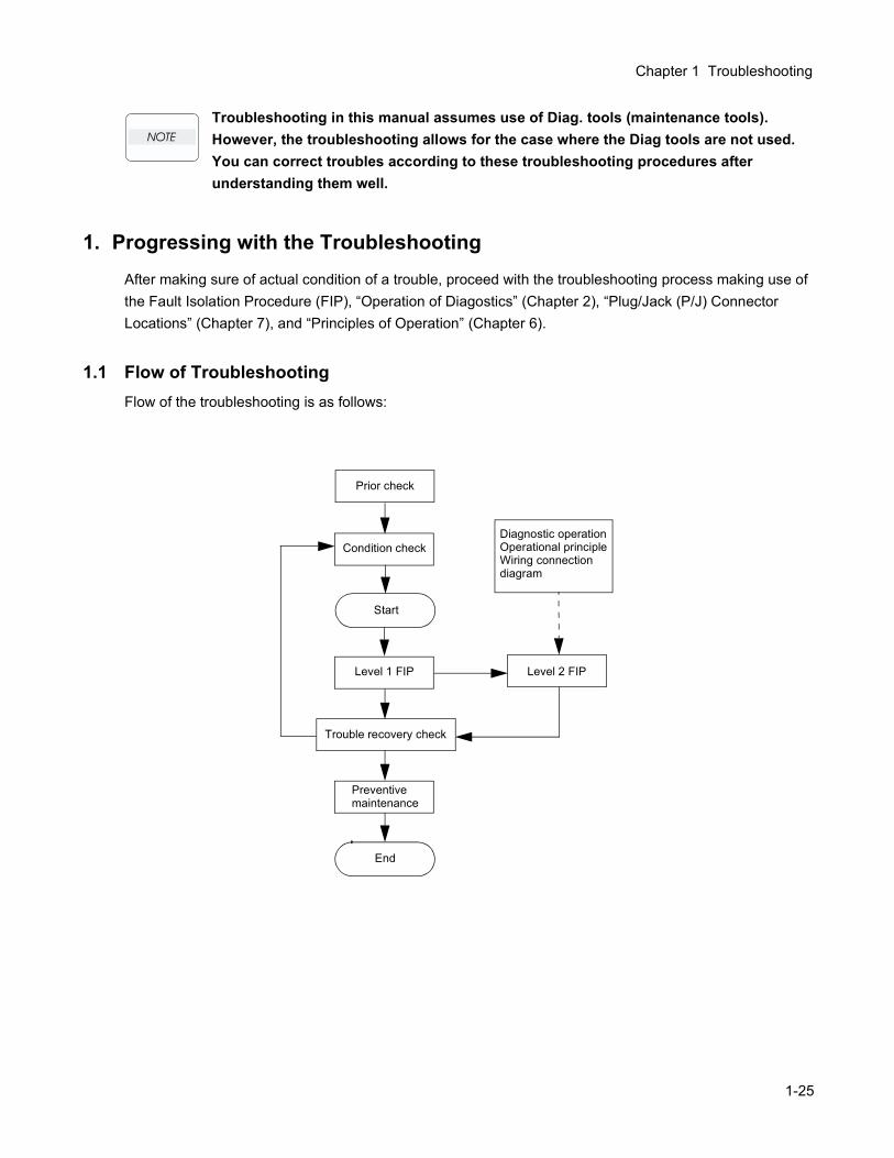
1.1 Flow of TroubleshootingFlow of the troubleshooting is as follows:
Prior check
Condition check
Start
Level 1 FIP
Trouble recovery check
Preventive maintenance
End
Diagnostic operationOperational principleWiring connection diagram
Level 2 FIP
1-25
1.2 Preparatory RequirementsBe sure to check the following items before starting any troubleshooting procedures:
1) Voltage of the power supply is within the specifications (measure the voltage at the electric outlet).
2) Power cord is free from breakage, short-circuit, disconnected wire, or incorrect connection in the power cord.
3) The laser printer is properly grounded.
4) The laser printer is not installed at a place subjected to too high temperature, too high humidity, too low temperature, too low humidity or rapid change of temperature.
5) The laser printer is not installed close to water service, humidifier, heat generating unit, or fire, in very dusty place, or a place exposed to air flow from the air conditioning system.
6) The laser printer is not installed in a place where volatile gas or inflammable gas is generated.
7) The laser printer is not installed under direct sunbeams.
8) The laser printer is installed in a well-ventilated place.
9) The laser printer is installed on a stout and stable plane.
10) Paper used meets specifications (standard paper is recommendable).
11) The laser printer is handled properly.
12) Parts which should be periodically replaced are replaced each time when specified number of sheets have been printed.
1-26
Chapter 1 Troubleshooting
1.3 Cautions for Service Operations1) Be sure to remove the power cord except when it is specifically required.
If the printer is kept ON, never touch the conductive parts while it is not specifically required.The power switch/inlet of LVPS is live even while the power supply is cut off. Never touch the live parts.
2) When checking some parts with covers removed and with the interlock and safety and power switches ON, remove the connector (P/J151) on the ROS ASSY except when it is specifically required.
When checking some parts with covers removed and with the interlock and safety and power switches ON, laser beams may be irradiated from the ROS ASSY. Since it is dangerous, be sure to remove the connector (P/J151) while it is not required.
3) When checking some parts with the left cover removed and power ON, be sure to remove the connector (P/J5011) on the HVPS while it is not required.
When checking some parts with the left cover removed and power ON, high voltage may be applied by the HVPS. Be sure to remove the connector (P/J5011) on the HVPS.When connecting the connector (P/J5011) on the HVPS according to the instructions of the FIP, never touch the HVPS and parts of high voltage.
4) When using Diag. tools or other tools of high voltage, be sure to keep them covered except when otherwise specified.
When using Diag.Tool or other tools of high voltage, never touch parts of high voltage.When using Diag.Tool or other tools of high voltage, be sure to follow the procedure of this manual.
5)When operating the driving units using the Diag or other tools, be sure to keep them covered unless otherwise specified.
When operating the driving units using the Diag or other tools, never touch the driving units. When operating the driving units using Diag or other tools, be sure to observe the procedures in this manual.
6) When touching hot parts, be careful not to get burnt.
7) Workers should wear a wrist band or the like to remove static electricity from their body, grounding their body while working.
1-27
1.4 Cautions for FIP Use1) It is assumed in the FIP that the printer controller (CONTROLLER PWB) is normally functioning. If the
trouble cannot be corrected by troubleshooting, replace the printer controller with a normal one and check for proper operation again.If the trouble is still not corrected, replace the major parts and then related parts in succession and confirm according to the procedure of the "Initial check" and "Major check parts".
2) When troubleshooting according to the FIP, normal HNB MCU PWB, Imaging Unit (PHD) or other parts may be necessary for isolation of failed parts. Prepare them in advance.
3) In the initial check according to the FIP, check only items which can be simply checked.
4) In the initial check according to the FIP, check the constitutive parts of the major check parts and related parts, as well as major check parts.
5) When working with the printer, Be sure to remove the power cord except when required specifically. Never touch live parts if not required, while the power cord is connected.
6) Connector condition is denoted as follows:[P/J12] Connector (P/J12) is connected.[P12] Plug side with the connector (P/J12) removed (except when attached directly to the board).[J12] Jack side with the connector (P/J12) removed (except when attached directly to the board).
7) [P/J1-2PIN <=> P/J3-4PIN] in the FIP means measurement with the plus side of the measuring instru-ment connected to [P/J1] and the minus side to [4PIN] of [P/J3].
8) [P/J<=>P/12] in the FIP means measurement for all terminals corresponding between [P/J1] and [P/J2] referring to "Wire connecting diagram".
9) In [P/J1-2PIN <=> P/J3-4PIN] in the FIP where voltage is measured, [P/J3-4PIN] on the rear minus side is always at the AG (analog ground), SG (signal ground), or RTN (return).Therefore, after checking of proper continuity between AGs, SGs, or RTNs respectively, the rear minus side can be connected to the PIN of AG, SG or RTN instead of [P/J3-4PIN].However, care should be taken not to mistake since [AG], [SG], and [RTN] are not on the same level.
10) Measure the voltage of small connectors with the special tool. Handle the tool with care, as the leading edge of the tool is pointed.
11) When measuring the voltage, set the PDH ASSY, FUSER ASSY, BRT ASSY and paper tray, close the FRONT COVER ASSY and power ON if not required specifically.
12) Numerical values in the FIP are only for standard. If numerical values are approximate, they should be considered permissible.
1-28
Chapter 1 Troubleshooting
13) Parts which are always removed to check as indicated in the FIP and procedures for that purpose arenot specifically referred to here. They should be handled carefully.
14) "Replacement" in the FIP indicates replacement of parts which are considered to be the source of trou-ble to be checked after replacing those parts, assemblies containing them, or parts (HIGH ASSY).
15) In the FIP, the paper pick-up unit by means of the paper tray at the lower part of the printer is referred to as "try 1", the first level of the paper pick-up unit feeder unit as "try 2", and the second level as the "tray3".
16) In the FIP, existence and non-existence of Diag tools (maintenance tools,) are distinguished in some cases. Correct troubles according to the instructions in the FIP.
17) In the FIP, procedures are differentiated depending on specifications. Correct troubles according to the instructions in the FIP.
18) For optional parts, some troubleshooting procedure may follow the manual for those options, of which you should take note.Keep those manuals for the optional parts when required.
1-29
2. Level 1 FIP
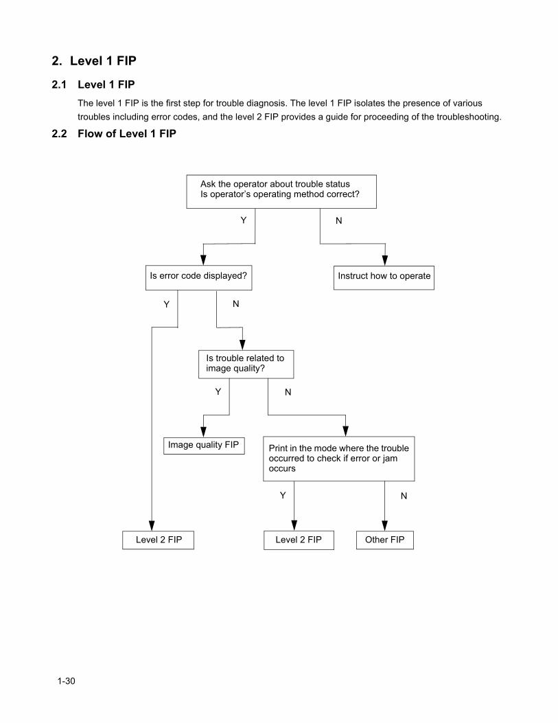
2.1 Level 1 FIPThe level 1 FIP is the first step for trouble diagnosis. The level 1 FIP isolates the presence of various troubles including error codes, and the level 2 FIP provides a guide for proceeding of the troubleshooting.
2.2 Flow of Level 1 FIP
Ask the operator about trouble statusIs operator’s operating method correct?
Is error code displayed? Instruct how to operate
Is trouble related to image quality?
Print in the mode where the trouble occurred to check if error or jam occurs
Level 2 FIP
Image quality FIP
Y N
N
NY
Y
NY
Level 2 FIP Other FIP
1-30
Chapter 1 Troubleshooting
3. Level 2 FIP
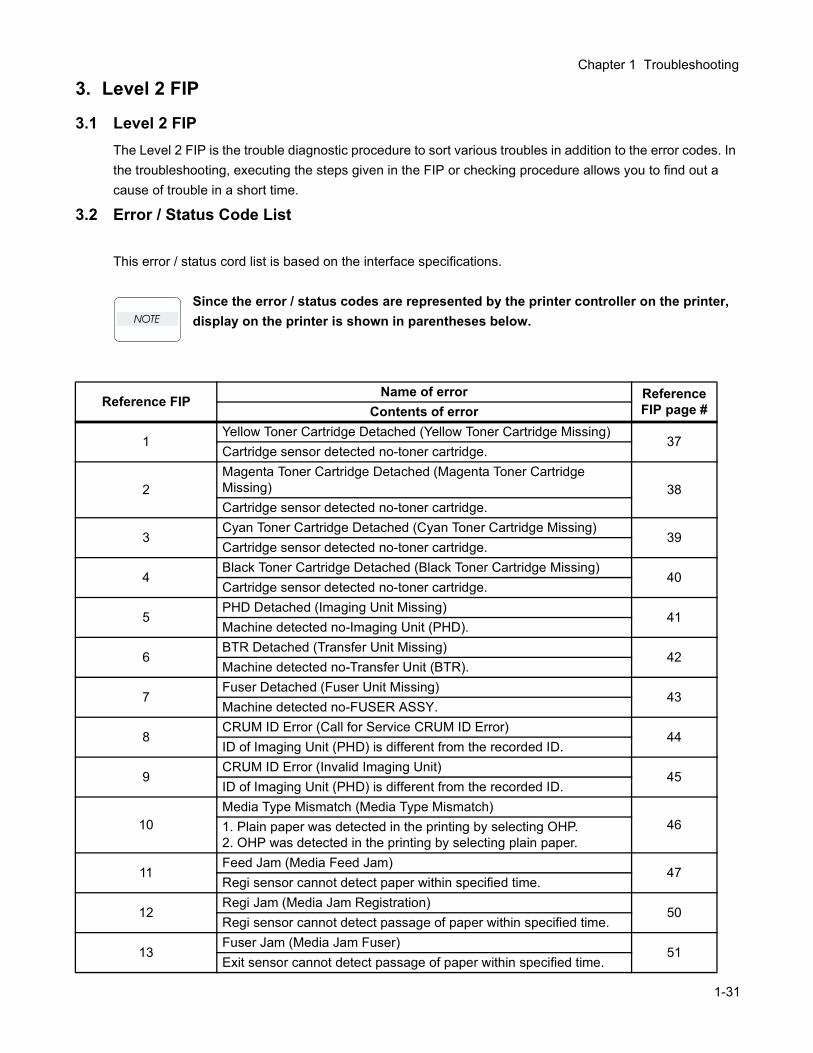
3.1 Level 2 FIPThe Level 2 FIP is the trouble diagnostic procedure to sort various troubles in addition to the error codes. In the troubleshooting, executing the steps given in the FIP or checking procedure allows you to find out a cause of trouble in a short time.
3.2 Error / Status Code List
This error / status cord list is based on the interface specifications.
Since the error / status codes are represented by the printer controller on the printer, display on the printer is shown in parentheses below.
Reference FIPName of error Reference
FIP page #Contents of error
1Yellow Toner Cartridge Detached (Yellow Toner Cartridge Missing)
37Cartridge sensor detected no-toner cartridge.
2Magenta Toner Cartridge Detached (Magenta Toner Cartridge Missing) 38Cartridge sensor detected no-toner cartridge.
3Cyan Toner Cartridge Detached (Cyan Toner Cartridge Missing)
39Cartridge sensor detected no-toner cartridge.
4Black Toner Cartridge Detached (Black Toner Cartridge Missing)
40Cartridge sensor detected no-toner cartridge.
5PHD Detached (Imaging Unit Missing)
41Machine detected no-Imaging Unit (PHD).
6BTR Detached (Transfer Unit Missing)
42Machine detected no-Transfer Unit (BTR).
7Fuser Detached (Fuser Unit Missing)
43Machine detected no-FUSER ASSY.
8CRUM ID Error (Call for Service CRUM ID Error)
44ID of Imaging Unit (PHD) is different from the recorded ID.
9CRUM ID Error (Invalid Imaging Unit)
45ID of Imaging Unit (PHD) is different from the recorded ID.
10Media Type Mismatch (Media Type Mismatch)
461. Plain paper was detected in the printing by selecting OHP.2. OHP was detected in the printing by selecting plain paper.
11Feed Jam (Media Feed Jam)
47Regi sensor cannot detect paper within specified time.
12Regi Jam (Media Jam Registration)
50Regi sensor cannot detect passage of paper within specified time.
13Fuser Jam (Media Jam Fuser)
51Exit sensor cannot detect passage of paper within specified time.
1-31
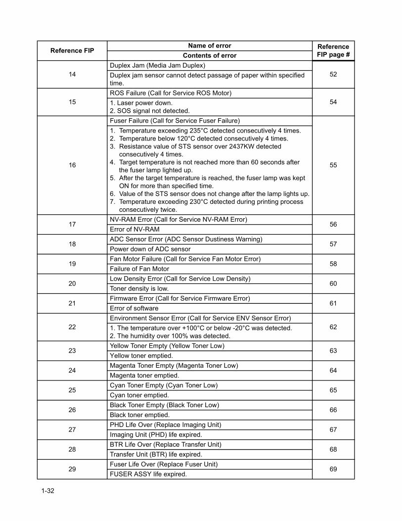
14Duplex Jam (Media Jam Duplex)
52Duplex jam sensor cannot detect passage of paper within specified time.
15ROS Failure (Call for Service ROS Motor)
541. Laser power down.2. SOS signal not detected.
16
Fuser Failure (Call for Service Fuser Failure)
55
1. Temperature exceeding 235°C detected consecutively 4 times.2. Temperature below 120°C detected consecutively 4 times.3. Resistance value of STS sensor over 2437KW detected
consecutively 4 times.4. Target temperature is not reached more than 60 seconds after the fuser lamp lighted up.5. After the target temperature is reached, the fuser lamp was kept
ON for more than specified time.6. Value of the STS sensor does not change after the lamp lights up.7. Temperature exceeding 230°C detected during printing process
consecutively twice.
17NV-RAM Error (Call for Service NV-RAM Error)
56Error of NV-RAM
18ADC Sensor Error (ADC Sensor Dustiness Warning)
57Power down of ADC sensor
19Fan Motor Failure (Call for Service Fan Motor Error)
58Failure of Fan Motor
20Low Density Error (Call for Service Low Density)
60Toner density is low.
21Firmware Error (Call for Service Firmware Error)
61Error of software
22Environment Sensor Error (Call for Service ENV Sensor Error)
621. The temperature over +100°C or below -20°C was detected.2. The humidity over 100% was detected.
23Yellow Toner Empty (Yellow Toner Low)
63Yellow toner emptied.
24Magenta Toner Empty (Magenta Toner Low)
64Magenta toner emptied.
25Cyan Toner Empty (Cyan Toner Low)
65Cyan toner emptied.
26Black Toner Empty (Black Toner Low)
66Black toner emptied.
27PHD Life Over (Replace Imaging Unit)
67Imaging Unit (PHD) life expired.
28BTR Life Over (Replace Transfer Unit)
68Transfer Unit (BTR) life expired.
29Fuser Life Over (Replace Fuser Unit)
69FUSER ASSY life expired.
Reference FIPName of error Reference
FIP page #Contents of error
1-32
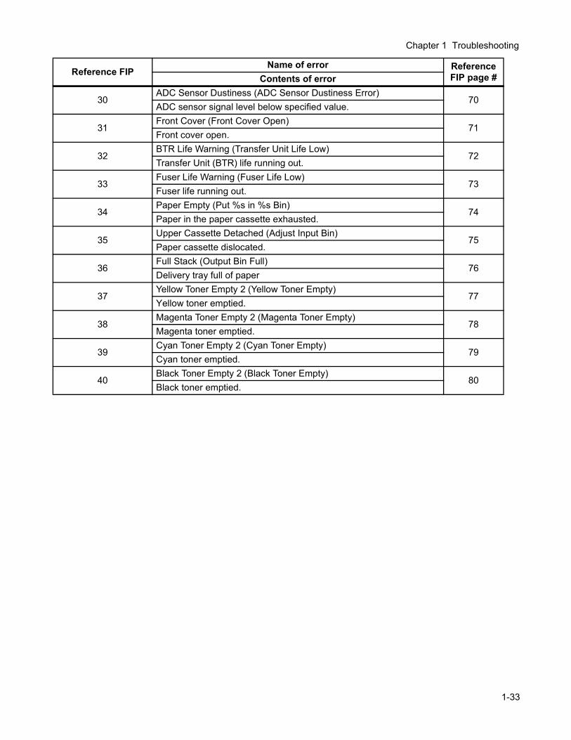
Chapter 1 Troubleshooting
30ADC Sensor Dustiness (ADC Sensor Dustiness Error)
70ADC sensor signal level below specified value.
31Front Cover (Front Cover Open)
71Front cover open.
32BTR Life Warning (Transfer Unit Life Low)
72Transfer Unit (BTR) life running out.
33Fuser Life Warning (Fuser Life Low)
73Fuser life running out.
34Paper Empty (Put %s in %s Bin)
74Paper in the paper cassette exhausted.
35Upper Cassette Detached (Adjust Input Bin)
75Paper cassette dislocated.
36Full Stack (Output Bin Full)
76Delivery tray full of paper
37Yellow Toner Empty 2 (Yellow Toner Empty)
77Yellow toner emptied.
38Magenta Toner Empty 2 (Magenta Toner Empty)
78Magenta toner emptied.
39Cyan Toner Empty 2 (Cyan Toner Empty)
79Cyan toner emptied.
40Black Toner Empty 2 (Black Toner Empty)
80Black toner emptied.
Reference FIPName of error Reference
FIP page #Contents of error
1-33
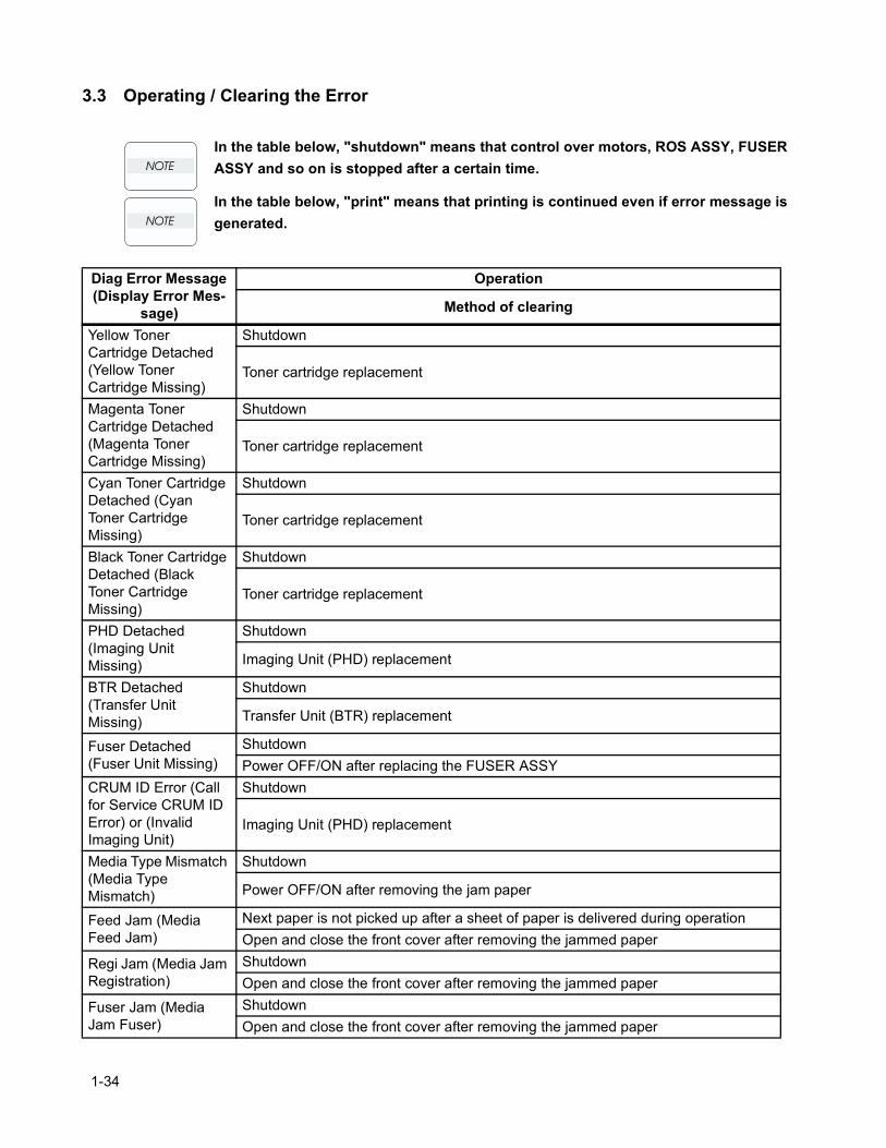
3.3 Operating / Clearing the Error
In the table below, "shutdown" means that control over motors, ROS ASSY, FUSER ASSY and so on is stopped after a certain time.
In the table below, "print" means that printing is continued even if error message is generated.
Diag Error Message (Display Error Mes-
sage)
Operation
Method of clearing
Yellow Toner Cartridge Detached (Yellow Toner Cartridge Missing)
Shutdown
Toner cartridge replacement
Magenta Toner Cartridge Detached (Magenta Toner Cartridge Missing)
Shutdown
Toner cartridge replacement
Cyan Toner Cartridge Detached (Cyan Toner Cartridge Missing)
Shutdown
Toner cartridge replacement
Black Toner Cartridge Detached (Black Toner Cartridge Missing)
Shutdown
Toner cartridge replacement
PHD Detached (Imaging Unit Missing)
Shutdown
Imaging Unit (PHD) replacement
BTR Detached (Transfer Unit Missing)
Shutdown
Transfer Unit (BTR) replacement
Fuser Detached (Fuser Unit Missing)
ShutdownPower OFF/ON after replacing the FUSER ASSY
CRUM ID Error (Call for Service CRUM ID Error) or (Invalid Imaging Unit)
Shutdown
Imaging Unit (PHD) replacement
Media Type Mismatch (Media Type Mismatch)
Shutdown
Power OFF/ON after removing the jam paper
Feed Jam (Media Feed Jam)
Next paper is not picked up after a sheet of paper is delivered during operationOpen and close the front cover after removing the jammed paper
Regi Jam (Media Jam Registration)
ShutdownOpen and close the front cover after removing the jammed paper
Fuser Jam (Media Jam Fuser)
ShutdownOpen and close the front cover after removing the jammed paper
1-34
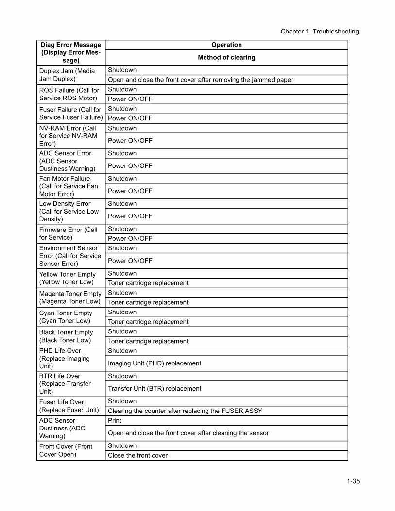
Chapter 1 Troubleshooting
Duplex Jam (Media Jam Duplex)
ShutdownOpen and close the front cover after removing the jammed paper
ROS Failure (Call for Service ROS Motor)
ShutdownPower ON/OFF
Fuser Failure (Call for Service Fuser Failure)
ShutdownPower ON/OFF
NV-RAM Error (Call for Service NV-RAM Error)
Shutdown
Power ON/OFF
ADC Sensor Error (ADC Sensor Dustiness Warning)
Shutdown
Power ON/OFF
Fan Motor Failure (Call for Service Fan Motor Error)
Shutdown
Power ON/OFF
Low Density Error (Call for Service Low Density)
Shutdown
Power ON/OFF
Firmware Error (Call for Service)
ShutdownPower ON/OFF
Environment Sensor Error (Call for Service Sensor Error)
Shutdown
Power ON/OFF
Yellow Toner Empty (Yellow Toner Low)
ShutdownToner cartridge replacement
Magenta Toner Empty (Magenta Toner Low)
ShutdownToner cartridge replacement
Cyan Toner Empty (Cyan Toner Low)
ShutdownToner cartridge replacement
Black Toner Empty (Black Toner Low)
ShutdownToner cartridge replacement
PHD Life Over (Replace Imaging Unit)
Shutdown
Imaging Unit (PHD) replacement
BTR Life Over (Replace Transfer Unit)
Shutdown
Transfer Unit (BTR) replacement
Fuser Life Over (Replace Fuser Unit)
ShutdownClearing the counter after replacing the FUSER ASSY
ADC Sensor Dustiness (ADC Warning)
Open and close the front cover after cleaning the sensor
Front Cover (Front Cover Open)
ShutdownClose the front cover
Diag Error Message (Display Error Mes-
sage)
Operation
Method of clearing
1-35
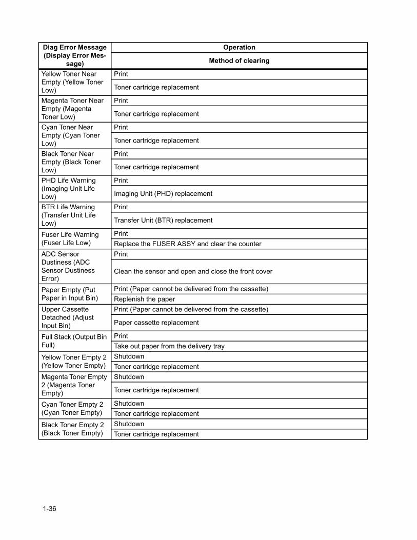
Yellow Toner Near Empty (Yellow Toner Low)
Toner cartridge replacement
Magenta Toner Near Empty (Magenta Toner Low)
Toner cartridge replacement
Cyan Toner Near Empty (Cyan Toner Low)
Toner cartridge replacement
Black Toner Near Empty (Black Toner Low)
Toner cartridge replacement
PHD Life Warning (Imaging Unit Life Low)
Imaging Unit (PHD) replacement
BTR Life Warning (Transfer Unit Life Low)
Transfer Unit (BTR) replacement
Fuser Life Warning (Fuser Life Low)
PrintReplace the FUSER ASSY and clear the counter
ADC Sensor Dustiness (ADC Sensor Dustiness Error)
Clean the sensor and open and close the front cover
Paper Empty (Put Paper in Input Bin)
Print (Paper cannot be delivered from the cassette)Replenish the paper
Upper Cassette Detached (Adjust Input Bin)
Print (Paper cannot be delivered from the cassette)
Paper cassette replacement
Full Stack (Output Bin Full)
PrintTake out paper from the delivery tray
Yellow Toner Empty 2 (Yellow Toner Empty)
ShutdownToner cartridge replacement
Magenta Toner Empty 2 (Magenta Toner Empty)
Shutdown
Toner cartridge replacement
Cyan Toner Empty 2 (Cyan Toner Empty)
ShutdownToner cartridge replacement
Black Toner Empty 2 (Black Toner Empty)
ShutdownToner cartridge replacement
Diag Error Message (Display Error Mes-
sage)
Operation
Method of clearing
1-36
Chapter 1 Troubleshooting
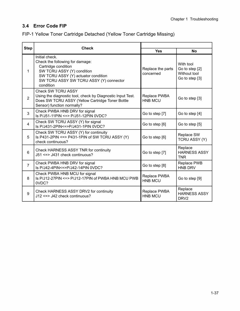
3.4 Error Code FIPFIP-1 Yellow Toner Cartridge Detached (Yellow Toner Cartridge Missing)
Step CheckYes No
1
Initial check.Check the following for damage:
Cartridge conditionSW TCRU ASSY (Y) conditionSW TCRU ASSY (Y) actuator conditionSW TCRU ASSY SW TCRU ASSY (Y) connector condition
Replace the parts concerned
With toolGo to step [2]Without toolGo to step [3]
2
Check SW TCRU ASSYUsing the diagnostic tool, check by Diagnostic Input Test.Does SW TCRU ASSY (Yellow Cartridge Toner Bottle Sensor) function normally?
Replace PWBA HNB MCU Go to step [3]
3 Check PWBA HNB DRV for signalIs P/J51-11PIN <=> P/J51-12PIN 0VDC? Go to step [7] Go to step [4]
4 Check SW TCRU ASSY (Y) for signalIs P/J431-2PIN<=>P/J431-1PIN 0VDC? Go to step [6] Go to step [5]
5Check SW TCRU ASSY (Y) for continuityIs P431-2PIN <=> P431-1PIN of SW TCRU ASSY (Y)check continuous?
Go to step [6] Replace SW TCRU ASSY (Y)
6 Check HARNESS ASSY TNR for continuityJ51 <=> J431 check continuous? Go to step [7]
Replace HARNESS ASSY TNR
7 Check PWBA HNB DRV for signalIs P/J42-4PIN<=>P/J42-14PIN 0VDC? Go to step [8] Replace PWB
HNB DRV
8Check PWBA HNB MCU for signalIs P/J12-27PIN <=> P/J12-17PIN of PWBA HNB MCU PWB 0VDC?
Replace PWBA HNB MCU Go to step [9]
9 Check HARNESS ASSY DRV2 for continuityJ12 <=> J42 check continuous?
Replace PWBA HNB MCU
Replace HARNESS ASSY DRV2
1-37
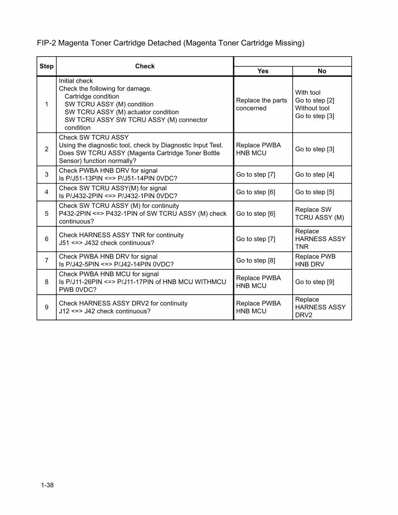
FIP-2 Magenta Toner Cartridge Detached (Magenta Toner Cartridge Missing)
Step CheckYes No
1
Initial checkCheck the following for damage.
Cartridge conditionSW TCRU ASSY (M) conditionSW TCRU ASSY (M) actuator conditionSW TCRU ASSY SW TCRU ASSY (M) connector condition
Replace the parts concerned
With toolGo to step [2]Without toolGo to step [3]
2
Check SW TCRU ASSYUsing the diagnostic tool, check by Diagnostic Input Test.Does SW TCRU ASSY (Magenta Cartridge Toner Bottle Sensor) function normally?
Replace PWBA HNB MCU Go to step [3]
3 Check PWBA HNB DRV for signalIs P/J51-13PIN <=> P/J51-14PIN 0VDC? Go to step [7] Go to step [4]
4 Check SW TCRU ASSY(M) for signalIs P/J432-2PIN <=> P/J432-1PIN 0VDC? Go to step [6] Go to step [5]
5Check SW TCRU ASSY (M) for continuityP432-2PIN <=> P432-1PIN of SW TCRU ASSY (M) check continuous?
Go to step [6] Replace SW TCRU ASSY (M)
6 Check HARNESS ASSY TNR for continuityJ51 <=> J432 check continuous? Go to step [7]
Replace HARNESS ASSY TNR
7 Check PWBA HNB DRV for signalIs P/J42-5PIN <=> P/J42-14PIN 0VDC? Go to step [8] Replace PWB
HNB DRV
8Check PWBA HNB MCU for signalIs P/J11-26PIN <=> P/J11-17PIN of HNB MCU WITHMCU PWB 0VDC?
Replace PWBA HNB MCU Go to step [9]
9 Check HARNESS ASSY DRV2 for continuityJ12 <=> J42 check continuous?
Replace PWBA HNB MCU
Replace HARNESS ASSY DRV2
1-38
Chapter 1 Troubleshooting
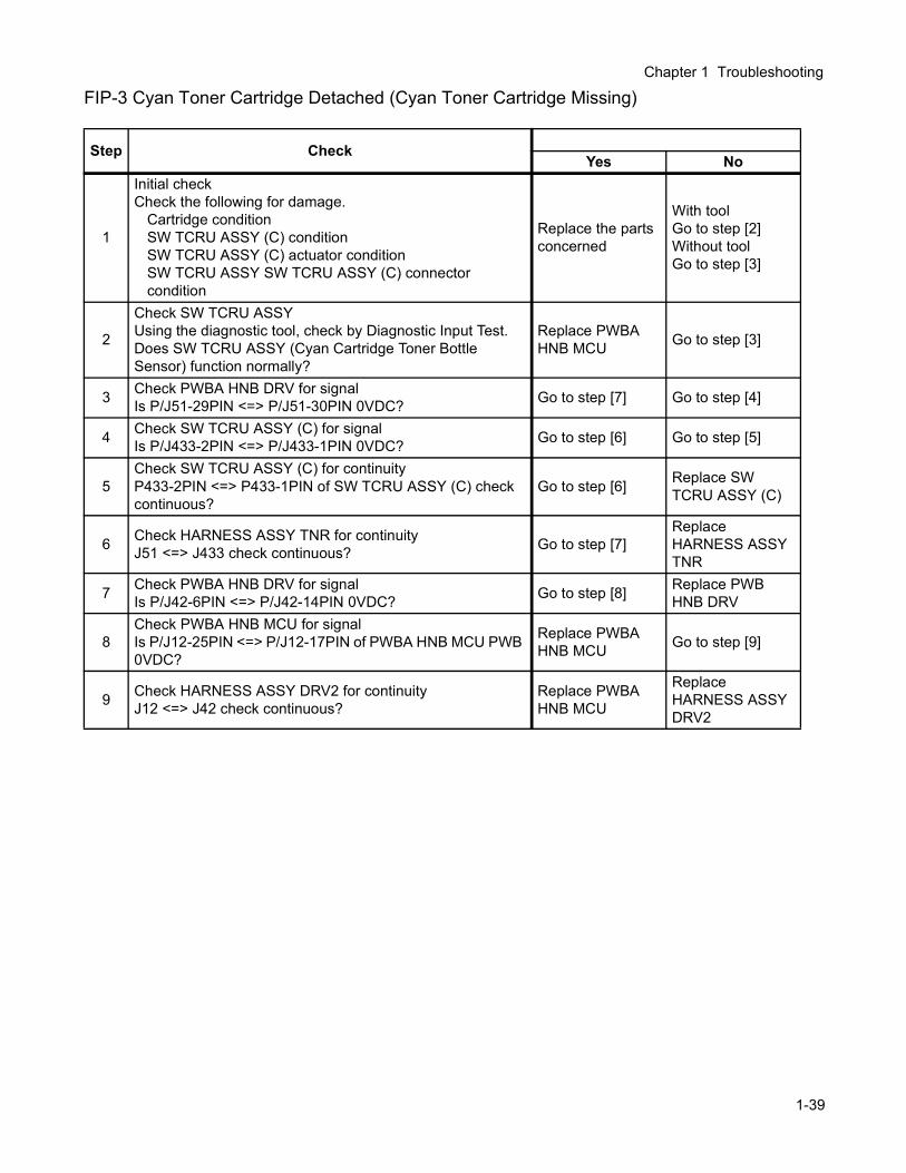
FIP-3 Cyan Toner Cartridge Detached (Cyan Toner Cartridge Missing)
Step CheckYes No
1
Initial checkCheck the following for damage.
Cartridge conditionSW TCRU ASSY (C) conditionSW TCRU ASSY (C) actuator conditionSW TCRU ASSY SW TCRU ASSY (C) connector condition
Replace the parts concerned
With toolGo to step [2]Without toolGo to step [3]
2
Check SW TCRU ASSYUsing the diagnostic tool, check by Diagnostic Input Test.Does SW TCRU ASSY (Cyan Cartridge Toner Bottle Sensor) function normally?
Replace PWBA HNB MCU Go to step [3]
3 Check PWBA HNB DRV for signalIs P/J51-29PIN <=> P/J51-30PIN 0VDC? Go to step [7] Go to step [4]
4 Check SW TCRU ASSY (C) for signalIs P/J433-2PIN <=> P/J433-1PIN 0VDC? Go to step [6] Go to step [5]
5Check SW TCRU ASSY (C) for continuityP433-2PIN <=> P433-1PIN of SW TCRU ASSY (C) check continuous?
Go to step [6] Replace SW TCRU ASSY (C)
6 Check HARNESS ASSY TNR for continuityJ51 <=> J433 check continuous? Go to step [7]
Replace HARNESS ASSY TNR
7 Check PWBA HNB DRV for signalIs P/J42-6PIN <=> P/J42-14PIN 0VDC? Go to step [8] Replace PWB
HNB DRV
8Check PWBA HNB MCU for signalIs P/J12-25PIN <=> P/J12-17PIN of PWBA HNB MCU PWB 0VDC?
Replace PWBA HNB MCU Go to step [9]
9 Check HARNESS ASSY DRV2 for continuityJ12 <=> J42 check continuous?
Replace PWBA HNB MCU
Replace HARNESS ASSY DRV2
1-39
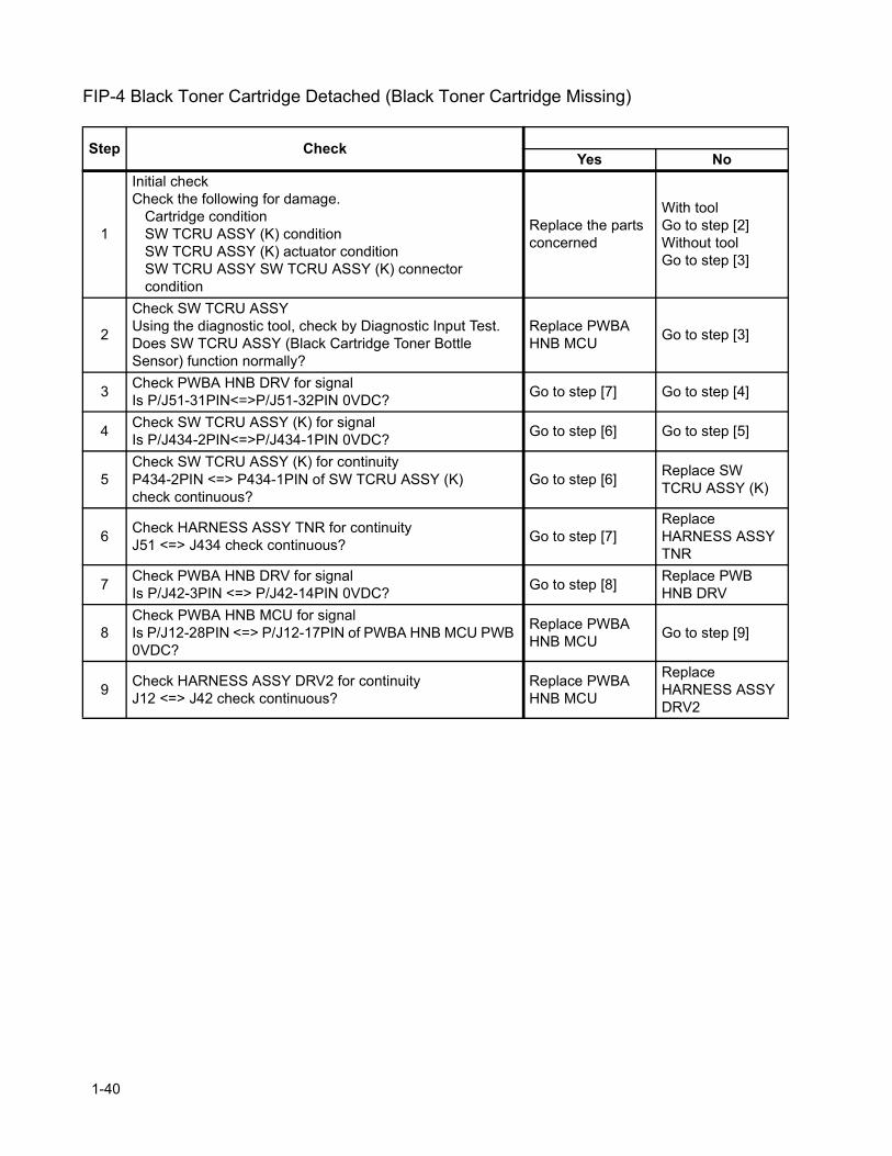
FIP-4 Black Toner Cartridge Detached (Black Toner Cartridge Missing)
Step CheckYes No
1
Initial checkCheck the following for damage.
Cartridge conditionSW TCRU ASSY (K) conditionSW TCRU ASSY (K) actuator conditionSW TCRU ASSY SW TCRU ASSY (K) connector condition
Replace the parts concerned
With toolGo to step [2]Without toolGo to step [3]
2
Check SW TCRU ASSYUsing the diagnostic tool, check by Diagnostic Input Test.Does SW TCRU ASSY (Black Cartridge Toner Bottle Sensor) function normally?
Replace PWBA HNB MCU Go to step [3]
3 Check PWBA HNB DRV for signalIs P/J51-31PIN<=>P/J51-32PIN 0VDC? Go to step [7] Go to step [4]
4 Check SW TCRU ASSY (K) for signalIs P/J434-2PIN<=>P/J434-1PIN 0VDC? Go to step [6] Go to step [5]
5Check SW TCRU ASSY (K) for continuityP434-2PIN <=> P434-1PIN of SW TCRU ASSY (K)check continuous?
Go to step [6] Replace SW TCRU ASSY (K)
6 Check HARNESS ASSY TNR for continuityJ51 <=> J434 check continuous? Go to step [7]
Replace HARNESS ASSY TNR
7 Check PWBA HNB DRV for signalIs P/J42-3PIN <=> P/J42-14PIN 0VDC? Go to step [8] Replace PWB
HNB DRV
8Check PWBA HNB MCU for signalIs P/J12-28PIN <=> P/J12-17PIN of PWBA HNB MCU PWB 0VDC?
Replace PWBA HNB MCU Go to step [9]
9 Check HARNESS ASSY DRV2 for continuityJ12 <=> J42 check continuous?
Replace PWBA HNB MCU
Replace HARNESS ASSY DRV2
1-40
Chapter 1 Troubleshooting
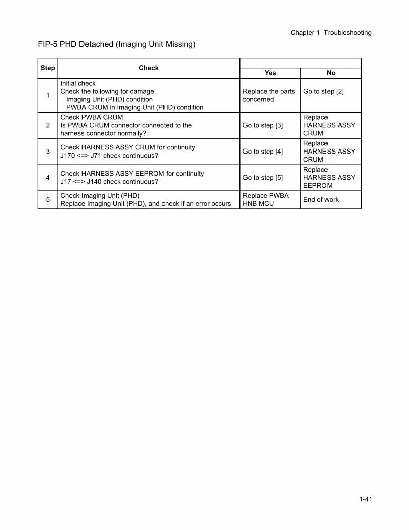
FIP-5 PHD Detached (Imaging Unit Missing)
Step CheckYes No
1
Initial checkCheck the following for damage.
Imaging Unit (PHD) conditionPWBA CRUM in Imaging Unit (PHD) condition
Replace the parts concerned
Go to step [2]
2Check PWBA CRUM Is PWBA CRUM connector connected to theharness connector normally?
Go to step [3]Replace HARNESS ASSYCRUM
3 Check HARNESS ASSY CRUM for continuityJ170 <=> J71 check continuous? Go to step [4]
Replace HARNESS ASSYCRUM
4 Check HARNESS ASSY EEPROM for continuityJ17 <=> J140 check continuous? Go to step [5]
Replace HARNESS ASSYEEPROM
5 Check Imaging Unit (PHD)Replace Imaging Unit (PHD), and check if an error occurs
Replace PWBA HNB MCU End of work
1-41
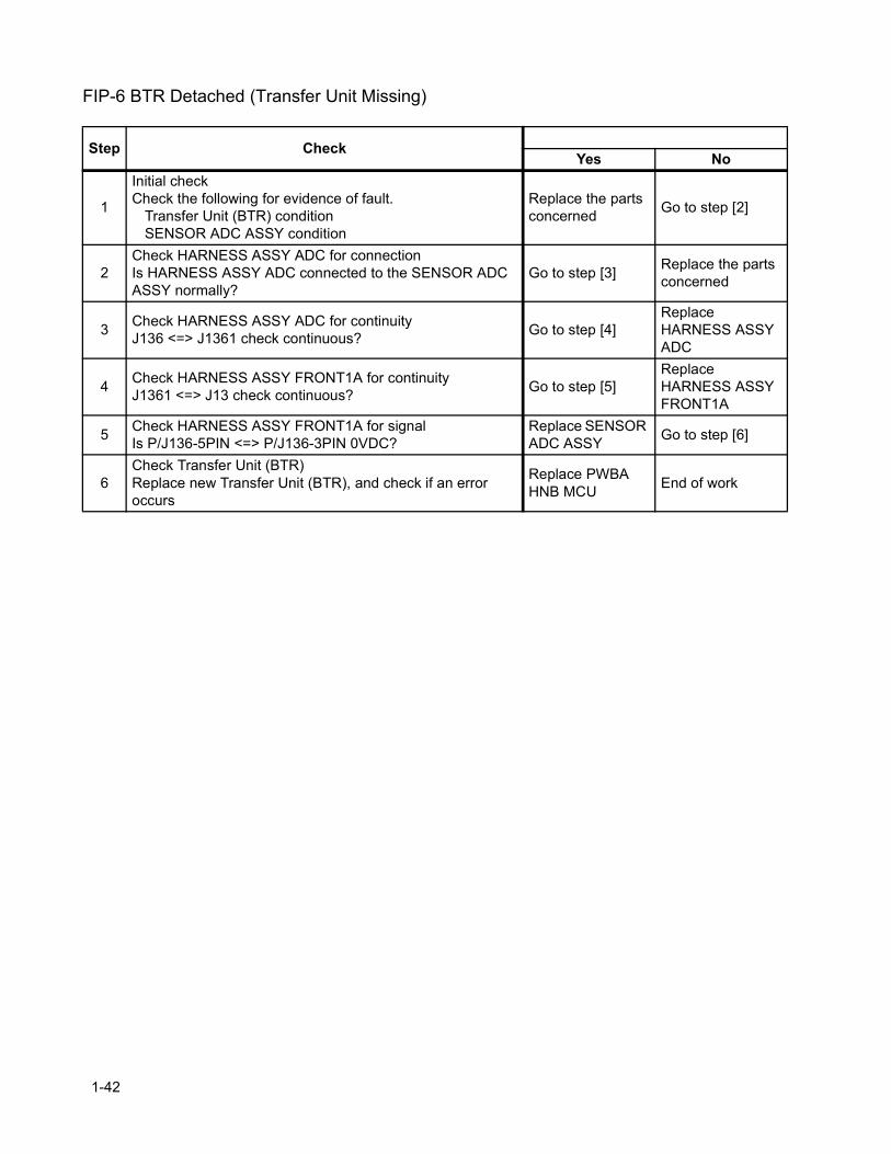
FIP-6 BTR Detached (Transfer Unit Missing)
Step CheckYes No
1
Initial checkCheck the following for evidence of fault.
Transfer Unit (BTR) conditionSENSOR ADC ASSY condition
Replace the parts concerned Go to step [2]
2Check HARNESS ASSY ADC for connectionIs HARNESS ASSY ADC connected to the SENSOR ADC ASSY normally?
Go to step [3] Replace the parts concerned
3 Check HARNESS ASSY ADC for continuityJ136 <=> J1361 check continuous? Go to step [4]
Replace HARNESS ASSY ADC
4 Check HARNESS ASSY FRONT1A for continuityJ1361 <=> J13 check continuous? Go to step [5]
Replace HARNESS ASSY FRONT1A
5 Check HARNESS ASSY FRONT1A for signalIs P/J136-5PIN <=> P/J136-3PIN 0VDC?
Replace SENSOR ADC ASSY Go to step [6]
6Check Transfer Unit (BTR)Replace new Transfer Unit (BTR), and check if an error occurs
Replace PWBA HNB MCU End of work
1-42
Chapter 1 Troubleshooting
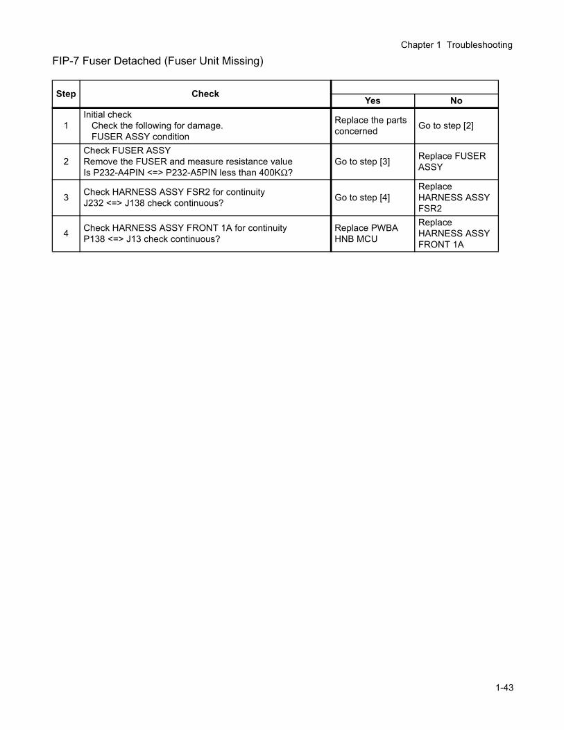
FIP-7 Fuser Detached (Fuser Unit Missing)
Step CheckYes No
1Initial check
Check the following for damage.FUSER ASSY condition
Replace the parts concerned Go to step [2]
2Check FUSER ASSYRemove the FUSER and measure resistance valueIs P232-A4PIN <=> P232-A5PIN less than 400KΩ?
Go to step [3] Replace FUSER ASSY
3 Check HARNESS ASSY FSR2 for continuityJ232 <=> J138 check continuous? Go to step [4]
Replace HARNESS ASSY FSR2
4 Check HARNESS ASSY FRONT 1A for continuityP138 <=> J13 check continuous?
Replace PWBA HNB MCU
Replace HARNESS ASSY FRONT 1A
1-43
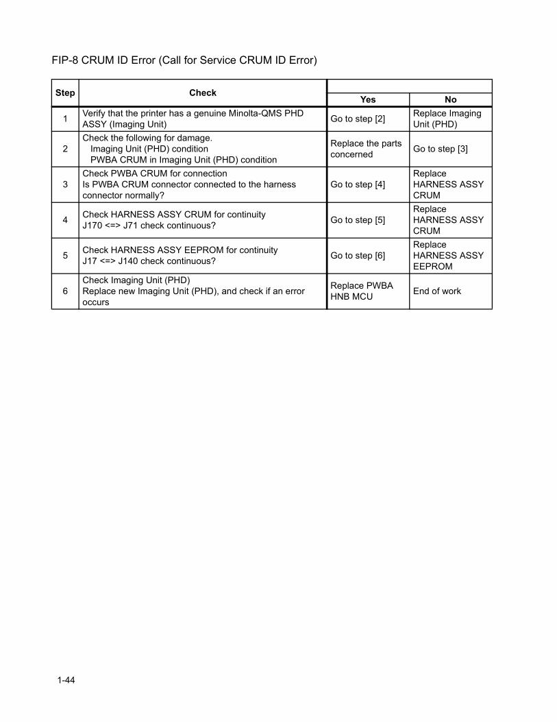
FIP-8 CRUM ID Error (Call for Service CRUM ID Error)
Step CheckYes No
1 Verify that the printer has a genuine Minolta-QMS PHD ASSY (Imaging Unit) Go to step [2] Replace Imaging
Unit (PHD)
2Check the following for damage.
Imaging Unit (PHD) conditionPWBA CRUM in Imaging Unit (PHD) condition
Replace the parts concerned Go to step [3]
3Check PWBA CRUM for connectionIs PWBA CRUM connector connected to the harness connector normally?
Go to step [4]Replace HARNESS ASSYCRUM
4 Check HARNESS ASSY CRUM for continuityJ170 <=> J71 check continuous? Go to step [5]
Replace HARNESS ASSYCRUM
5 Check HARNESS ASSY EEPROM for continuityJ17 <=> J140 check continuous? Go to step [6]
Replace HARNESS ASSYEEPROM
6Check Imaging Unit (PHD)Replace new Imaging Unit (PHD), and check if an error occurs
Replace PWBA HNB MCU End of work
1-44
Chapter 1 Troubleshooting
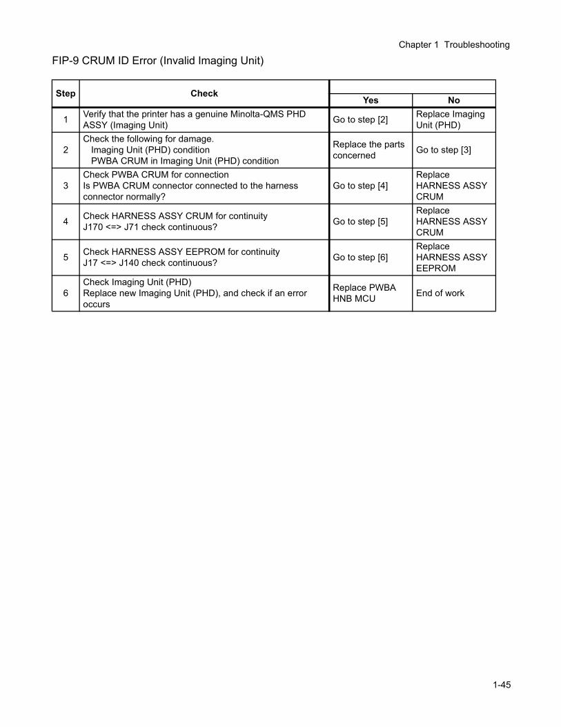
FIP-9 CRUM ID Error (Invalid Imaging Unit)
Step CheckYes No
1 Verify that the printer has a genuine Minolta-QMS PHD ASSY (Imaging Unit) Go to step [2] Replace Imaging
Unit (PHD)
2Check the following for damage.
Imaging Unit (PHD) conditionPWBA CRUM in Imaging Unit (PHD) condition
Replace the parts concerned Go to step [3]
3Check PWBA CRUM for connectionIs PWBA CRUM connector connected to the harness connector normally?
Go to step [4]Replace HARNESS ASSYCRUM
4 Check HARNESS ASSY CRUM for continuityJ170 <=> J71 check continuous? Go to step [5]
Replace HARNESS ASSYCRUM
5 Check HARNESS ASSY EEPROM for continuityJ17 <=> J140 check continuous? Go to step [6]
Replace HARNESS ASSYEEPROM
6Check Imaging Unit (PHD)Replace new Imaging Unit (PHD), and check if an error occurs
Replace PWBA HNB MCU End of work
1-45
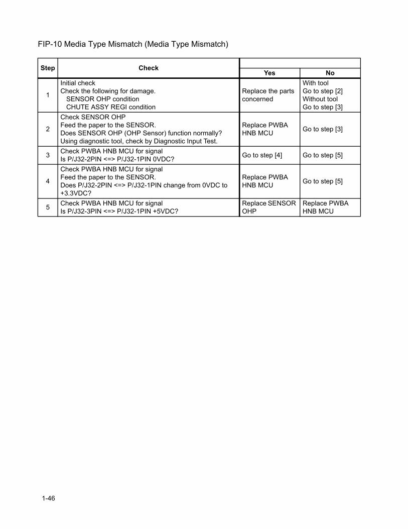
FIP-10 Media Type Mismatch (Media Type Mismatch)
Step CheckYes No
1
Initial checkCheck the following for damage.
SENSOR OHP conditionCHUTE ASSY REGI condition
Replace the parts concerned
With toolGo to step [2]Without toolGo to step [3]
2
Check SENSOR OHPFeed the paper to the SENSOR.Does SENSOR OHP (OHP Sensor) function normally?Using diagnostic tool, check by Diagnostic Input Test.
Replace PWBA HNB MCU Go to step [3]
3 Check PWBA HNB MCU for signalIs P/J32-2PIN <=> P/J32-1PIN 0VDC? Go to step [4] Go to step [5]
4
Check PWBA HNB MCU for signalFeed the paper to the SENSOR.Does P/J32-2PIN <=> P/J32-1PIN change from 0VDC to +3.3VDC?
Replace PWBA HNB MCU Go to step [5]
5 Check PWBA HNB MCU for signalIs P/J32-3PIN <=> P/J32-1PIN +5VDC?
Replace SENSOR OHP
Replace PWBA HNB MCU
1-46
Chapter 1 Troubleshooting
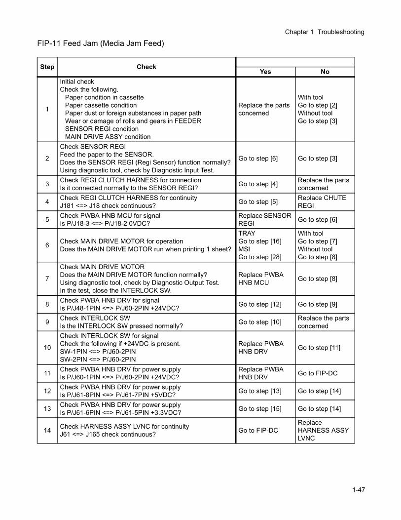
FIP-11 Feed Jam (Media Jam Feed)
Step CheckYes No
1
Initial checkCheck the following.
Paper condition in cassettePaper cassette conditionPaper dust or foreign substances in paper pathWear or damage of rolls and gears in FEEDERSENSOR REGI conditionMAIN DRIVE ASSY condition
Replace the parts concerned
With toolGo to step [2]Without toolGo to step [3]
2
Check SENSOR REGIFeed the paper to the SENSOR.Does the SENSOR REGI (Regi Sensor) function normally?Using diagnostic tool, check by Diagnostic Input Test.
Go to step [6] Go to step [3]
3 Check REGI CLUTCH HARNESS for connectionIs it connected normally to the SENSOR REGI? Go to step [4] Replace the parts
concerned
4 Check REGI CLUTCH HARNESS for continuityJ181 <=> J18 check continuous? Go to step [5] Replace CHUTE
REGI
5 Check PWBA HNB MCU for signalIs P/J18-3 <=> P/J18-2 0VDC?
Replace SENSOR REGI Go to step [6]
6 Check MAIN DRIVE MOTOR for operationDoes the MAIN DRIVE MOTOR run when printing 1 sheet?
TRAYGo to step [16]MSIGo to step [28]
With toolGo to step [7]Without toolGo to step [8]
7
Check MAIN DRIVE MOTORDoes the MAIN DRIVE MOTOR function normally?Using diagnostic tool, check by Diagnostic Output Test.In the test, close the INTERLOCK SW.
Replace PWBA HNB MCU Go to step [8]
8 Check PWBA HNB DRV for signalIs P/J48-1PIN <=> P/J60-2PIN +24VDC? Go to step [12] Go to step [9]
9 Check INTERLOCK SWIs the INTERLOCK SW pressed normally? Go to step [10] Replace the parts
concerned
10
Check INTERLOCK SW for signalCheck the following if +24VDC is present.SW-1PIN <=> P/J60-2PINSW-2PIN <=> P/J60-2PIN
Replace PWBA HNB DRV Go to step [11]
11 Check PWBA HNB DRV for power supplyIs P/J60-1PIN <=> P/J60-2PIN +24VDC?
Replace PWBA HNB DRV Go to FIP-DC
12 Check PWBA HNB DRV for power supplyIs P/J61-8PIN <=> P/J61-7PIN +5VDC? Go to step [13] Go to step [14]
13 Check PWBA HNB DRV for power supplyIs P/J61-6PIN <=> P/J61-5PIN +3.3VDC? Go to step [15] Go to step [14]
14 Check HARNESS ASSY LVNC for continuityJ61 <=> J165 check continuous? Go to FIP-DC
Replace HARNESS ASSY LVNC
1-47
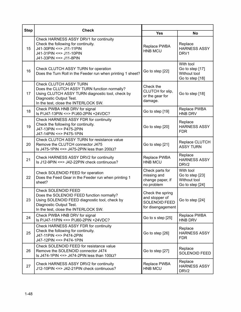
15
Check HARNESS ASSY DRV1 for continuityCheck the following for continuity.J41-30PIN <=> J11-11PINJ41-31PIN <=> J11-10PINJ41-33PIN <=> J11-8PIN
Replace PWBA HNB MCU
Replace HARNESS ASSY DRV1
16 Check CLUTCH ASSY TURN for operationDoes the Turn Roll in the Feeder run when printing 1 sheet? Go to step [22]
With toolGo to step [17]Without toolGo to step [18]
17
Check CLUTCH ASSY TURNDoes the CLUTCH ASSY TURN function normally?Using CLUTCH ASSY TURN diagnostic tool, check by Diagnostic Output Test.In the test, close the INTERLOCK SW.
Check the CLUTCH for slip, or the gear for damage.
Go to step [18]
18 Check PWBA HNB DRV for signalIs P/J47-13PIN <=> P/J60-2PIN +24VDC? Go to step [19] Replace PWBA
HNB DRV
19
Check HARNESS ASSY FDR for continuityCheck the following for continuity.J47-13PIN <=> P475-2PINJ47-14PIN <=> P475-1PIN
Go to step [20]Replace HARNESS ASSY FDR
20Check CLUTCH ASSY TURN for resistance valueRemove the CLUTCH connector J475Is J475-1PIN <=> J475-2PIN less than 200Ω?
Go to step [21] Replace CLUTCH ASSY TURN
21 Check HARNESS ASSY DRV2 for continuityIs J12-9PIN <=> J42-22PIN check continuous?
Replace PWBA HNB MCU
Replace HARNESS ASSY DRV2
22Check SOLENOID FEED for operationDoes the Feed Gear in the Feeder run when printing 1 sheet?
Check parts for missing and change paper, if no problem
With toolGo to step [23]Without toolGo to step [24]
23
Check SOLENOID FEEDDoes the SOLENOID FEED function normally?Using SOLENOID FEED diagnostic tool, check by Diagnostic Output Test.In the test, close the INTERLOCK SW.
Check the spring and stopper of SOLENOID FEED for disengagement
Go to step [24]
24 Check PWBA HNB DRV for signalIs P/J47-11PIN <=> P/J60-2PIN +24VDC? Go to s step [25] Replace PWBA
HNB DRV
25
Check HARNESS ASSY FDR for continuityCheck the following for continuity.J47-11PIN <=> P474-2PINJ47-12PIN <=> P474-1PIN
Go to step [26]Replace HARNESS ASSY FDR
26Check SOLENOID FEED for resistance valueRemove the SOLENOID connector J474Is J474-1PIN <=> J474-2PIN less than 100Ω?
Go to step [27] Replace SOLENOID FEED
27 Check HARNESS ASSY DRV2 for continuityJ12-10PIN <=> J42-21PIN check continuous?
Replace PWBA HNB MCU
Replace HARNESS ASSYDRV2
Step CheckYes No
1-48
Chapter 1 Troubleshooting
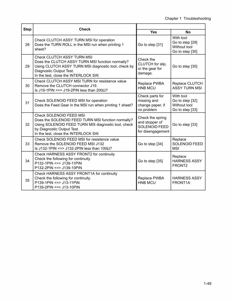
28Check CLUTCH ASSY TURN MSI for operationDoes the TURN ROLL in the MSI run when printing 1 sheet?
Go to step [31]
With toolGo to step [29]Without toolGo to step [30]
29
Check CLUTCH ASSY TURN MSIDoes the CLUTCH ASSY TURN MSI function normally?Using CLUTCH ASSY TURN MSI diagnostic tool, check by Diagnostic Output Test.In the test, close the INTERLOCK SW.
Check the CLUTCH for slip, or the gear for damage.
Go to step [30]
30Check CLUTCH ASSY MSI TURN for resistance valueRemove the CLUTCH connector J19.Is J19-1PIN <=> J19-2PIN less than 200Ω?
Replace PWBA HNB MCU
Replace CLUTCH ASSY TURN MSI
31 Check SOLENOID FEED MSI for operationDoes the Feed Gear in the MSI run when printing 1 sheet?
Check parts for missing and change paper, if no problem
With toolGo to step [32]Without toolGo to step [33]
32
Check SOLENOID FEED MSIDoes the SOLENOID FEED TURN MSI function normally?Using SOLENOID FEED TURN MIS diagnostic tool, check by Diagnostic Output Test.In the test, close the INTERLOCK SW.
Check the spring and stopper of SOLENOID FEED for disengagement
Go to step [33]
33Check SOLENOID FEED MSI for resistance valueRemove the SOLENOID FEED MSI J132Is J132-1PIN <=> J132-2PIN less than 100Ω?
Go to step [34]Replace SOLENOID FEED MSI
34
Check HARNESS ASSY FRONT2 for continuityCheck the following for continuity.P132-1PIN <=> J139-11PINP132-2PIN <=> J139-10PIN
Go to step [35]Replace HARNESS ASSY FRONT2
35
Check HARNESS ASSY FRONT1A for continuityCheck the following for continuity.P139-1PIN <=> J13-11PINP139-2PIN <=> J13-10PIN
Replace PWBA HNB MCU
HARNESS ASSY FRONT1A
Step CheckYes No
1-49
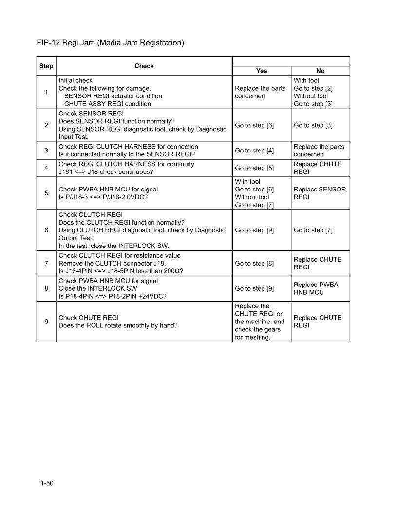
FIP-12 Regi Jam (Media Jam Registration)
Step CheckYes No
1
Initial checkCheck the following for damage.
SENSOR REGI actuator conditionCHUTE ASSY REGI condition
Replace the parts concerned
With toolGo to step [2]Without toolGo to step [3]
2
Check SENSOR REGIDoes SENSOR REGI function normally?Using SENSOR REGI diagnostic tool, check by Diagnostic Input Test.
Go to step [6] Go to step [3]
3 Check REGI CLUTCH HARNESS for connectionIs it connected normally to the SENSOR REGI? Go to step [4] Replace the parts
concerned
4 Check REGI CLUTCH HARNESS for continuityJ181 <=> J18 check continuous? Go to step [5] Replace CHUTE
REGI
5 Check PWBA HNB MCU for signalIs P/J18-3 <=> P/J18-2 0VDC?
With toolGo to step [6]Without toolGo to step [7]
Replace SENSOR REGI
6
Check CLUTCH REGIDoes the CLUTCH REGI function normally?Using CLUTCH REGI diagnostic tool, check by Diagnostic Output Test.In the test, close the INTERLOCK SW.
Go to step [9] Go to step [7]
7Check CLUTCH REGI for resistance valueRemove the CLUTCH connector J18.Is J18-4PIN <=> J18-5PIN less than 200Ω?
Go to step [8] Replace CHUTE REGI
8Check PWBA HNB MCU for signalClose the INTERLOCK SWIs P18-4PIN <=> P18-2PIN +24VDC?
Go to step [9] Replace PWBA HNB MCU
9 Check CHUTE REGIDoes the ROLL rotate smoothly by hand?
Replace the CHUTE REGI on the machine, and check the gears for meshing.
Replace CHUTE REGI
1-50
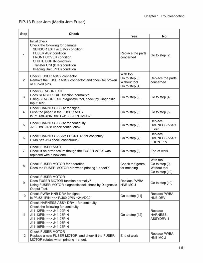
Chapter 1 Troubleshooting
FIP-13 Fuser Jam (Media Jam Fuser)
Step CheckYes No
1
Initial checkCheck the following for damage.
SENSOR EXIT actuator conditionFUSER ASY conditionFRONT COVER conditionCHUTE DUP IN conditionTransfer Unit (BTR) conditionImaging Unit (PHD) condition
Replace the parts concerned Go to step [2]
2Check FUSER ASSY connectorRemove the FUSER ASSY connector, and check for broken or curved pins.
With toolGo to step [3]Without toolGo to step [4]
Replace the parts concerned
3
Check SENSOR EXITDoes SENSOR EXIT function normally?Using SENSOR EXIT diagnostic tool, check by Diagnostic Input Test.
Go to step [9] Go to step [4]
4Check HARNESS FSR2 for signalPush the paper in the FUSER ASSYIs P/J138-3PIN <=> P/J138-2PIN 0VDC?
Go to step [6] Go to step [5]
5 Check HARNESS FSR2 for continuityJ232 <=> J138 check continuous? Go to step [6]
Replace HARNESS ASSY FSR2
6 Check HARNESS ASSY FRONT 1A for continuityP138 <=> J13 check continuous? Go to step [7]
Replace HARNESS ASSY FRONT 1A
7Check FUSER ASSYCheck if an error occurs though the FUSER ASSY was replaced with a new one.
Go to step [9] End of work
8 Check FUSER MOTOR for operationDoes the FUSER MOTOR run when printing 1 sheet?
Check the gears for meshing
With toolGo to step [9]Without toolGo to step [10]
9
Check FUSER MOTORDoes FUSER MOTOR function normally?Using FUSER MOTOR diagnostic tool, check by Diagnostic Output Test.
Replace PWBA HNB MCU Go to step [10]
10 Check PWBA HNB DRV for signalIs P/J52-1PIN <=> P/J60-2PIN +24VDC? Go to step [11] Replace PWBA
HNB DRV
11
Check HARNESS ASSY DRV 1 for continuityCheck the following for continuity.J11-12PIN <=> J41-29PINJ11-13PIN <=> J41-28PINJ11-14PIN <=> J41-27PINJ11-15PIN <=> J41-26PINJ11-16PIN <=> J41-25PIN
Go to step [12]Replace HARNESS ASSYDRV 1
12Check FUSER MOTORReplace a new FUSER MOTOR, and check if the FUSERMOTOR rotates when printing 1 sheet.
End of work Replace PWBA HNB MCU
1-51
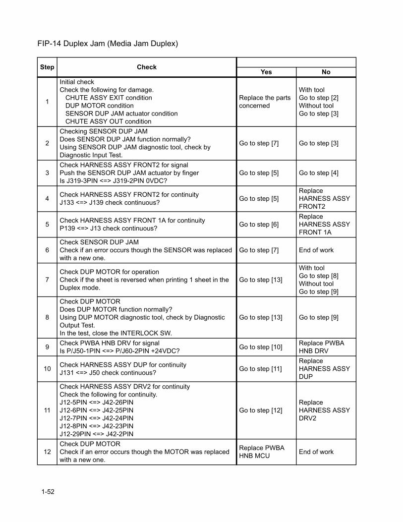
FIP-14 Duplex Jam (Media Jam Duplex)
Step CheckYes No
1
Initial checkCheck the following for damage.
CHUTE ASSY EXIT conditionDUP MOTOR conditionSENSOR DUP JAM actuator conditionCHUTE ASSY OUT condition
Replace the parts concerned
With toolGo to step [2]Without toolGo to step [3]
2
Checking SENSOR DUP JAMDoes SENSOR DUP JAM function normally?Using SENSOR DUP JAM diagnostic tool, check by Diagnostic Input Test.
Go to step [7] Go to step [3]
3Check HARNESS ASSY FRONT2 for signalPush the SENSOR DUP JAM actuator by fingerIs J319-3PIN <=> J319-2PIN 0VDC?
Go to step [5] Go to step [4]
4 Check HARNESS ASSY FRONT2 for continuityJ133 <=> J139 check continuous? Go to step [5]
Replace HARNESS ASSYFRONT2
5 Check HARNESS ASSY FRONT 1A for continuityP139 <=> J13 check continuous? Go to step [6]
Replace HARNESS ASSYFRONT 1A
6Check SENSOR DUP JAMCheck if an error occurs though the SENSOR was replaced with a new one.
Go to step [7] End of work
7Check DUP MOTOR for operationCheck if the sheet is reversed when printing 1 sheet in the Duplex mode.
Go to step [13]
With toolGo to step [8]Without toolGo to step [9]
8
Check DUP MOTORDoes DUP MOTOR function normally?Using DUP MOTOR diagnostic tool, check by Diagnostic Output Test.In the test, close the INTERLOCK SW.
Go to step [13] Go to step [9]
9 Check PWBA HNB DRV for signalIs P/J50-1PIN <=> P/J60-2PIN +24VDC? Go to step [10] Replace PWBA
HNB DRV
10 Check HARNESS ASSY DUP for continuityJ131 <=> J50 check continuous? Go to step [11]
Replace HARNESS ASSY DUP
11
Check HARNESS ASSY DRV2 for continuityCheck the following for continuity.J12-5PIN <=> J42-26PINJ12-6PIN <=> J42-25PINJ12-7PIN <=> J42-24PINJ12-8PIN <=> J42-23PINJ12-29PIN <=> J42-2PIN
Go to step [12]Replace HARNESS ASSYDRV2
12Check DUP MOTORCheck if an error occurs though the MOTOR was replaced with a new one.
Replace PWBA HNB MCU End of work
1-52

Chapter 1 Troubleshooting
13 Does the EXIT ROLL rotate smoothly by hand? Check the sheets for gear or skew
Check the gears for foreign substances
Step CheckYes No
1-53

FIP-15 ROS Failure (Call for Service ROS Motor)
Step CheckYes No
1 Check HARNESS ASSY ROSKA for continuityJ15 <=> P151 check continuous?
Replace ROS ASSY
Replace HARNESS ASSYROSKA
1-54
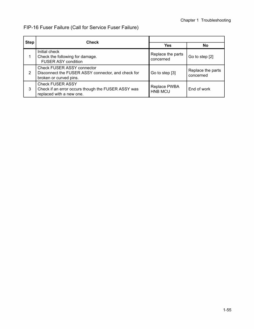
Chapter 1 Troubleshooting
FIP-16 Fuser Failure (Call for Service Fuser Failure)
Step CheckYes No
1Initial checkCheck the following for damage.
FUSER ASY condition
Replace the parts concerned Go to step [2]
2Check FUSER ASSY connectorDisconnect the FUSER ASSY connector, and check for broken or curved pins.
Go to step [3] Replace the parts concerned
3Check FUSER ASSYCheck if an error occurs though the FUSER ASSY was replaced with a new one.
Replace PWBA HNB MCU End of work
1-55

FIP-17 NV-RAM Error (Call for Service NVRAM Error)
Step CheckYes No
1 Does an error occur even if the power is turned off and on? Replace PWBA HNB MCU
If the error recurs, replace PWBA HNB MCU
1-56
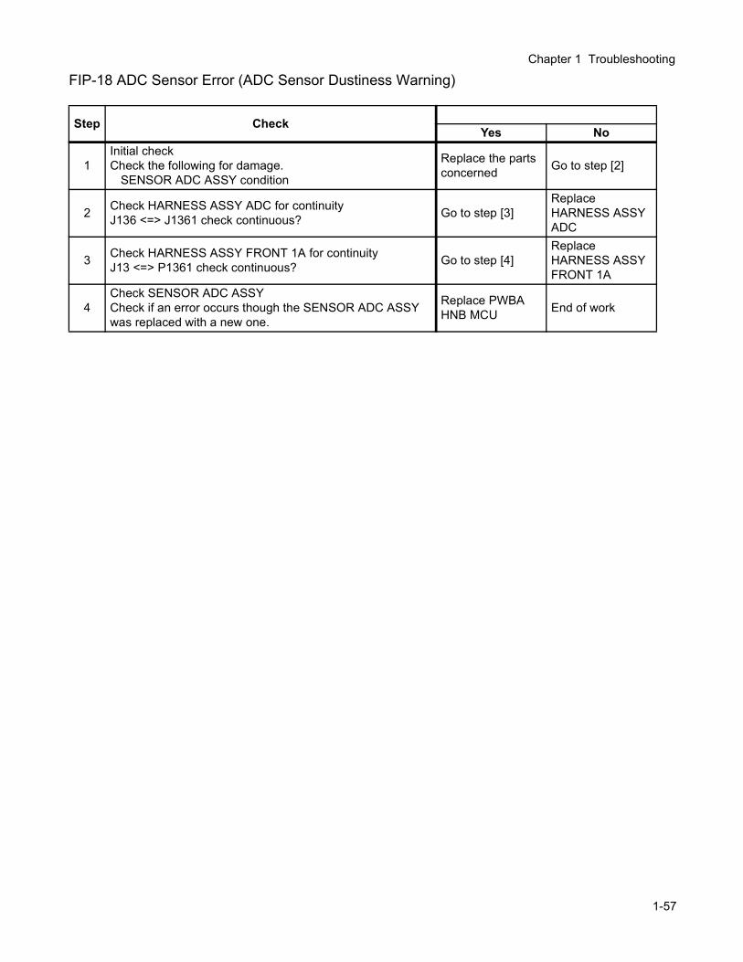
Chapter 1 Troubleshooting
FIP-18 ADC Sensor Error (ADC Sensor Dustiness Warning)
Step CheckYes No
1Initial checkCheck the following for damage.
SENSOR ADC ASSY condition
Replace the parts concerned Go to step [2]
2 Check HARNESS ASSY ADC for continuityJ136 <=> J1361 check continuous? Go to step [3]
Replace HARNESS ASSY ADC
3 Check HARNESS ASSY FRONT 1A for continuityJ13 <=> P1361 check continuous? Go to step [4]
Replace HARNESS ASSYFRONT 1A
4Check SENSOR ADC ASSYCheck if an error occurs though the SENSOR ADC ASSY was replaced with a new one.
Replace PWBA HNB MCU End of work
1-57
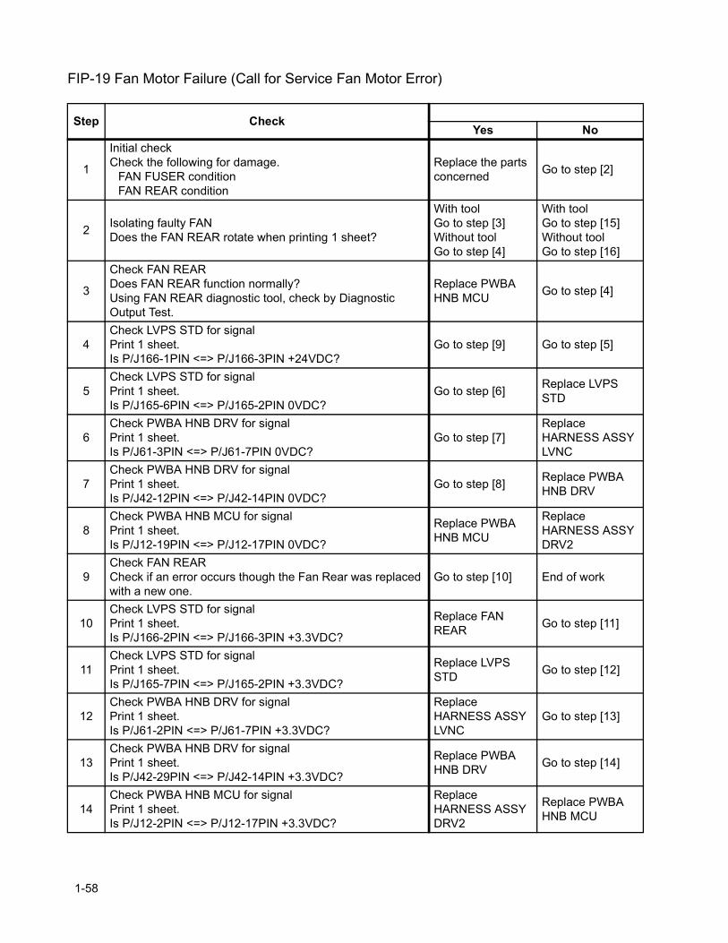
FIP-19 Fan Motor Failure (Call for Service Fan Motor Error)
Step CheckYes No
1
Initial checkCheck the following for damage.
FAN FUSER conditionFAN REAR condition
Replace the parts concerned Go to step [2]
2 Isolating faulty FANDoes the FAN REAR rotate when printing 1 sheet?
With toolGo to step [3]Without toolGo to step [4]
With toolGo to step [15]Without toolGo to step [16]
3
Check FAN REARDoes FAN REAR function normally?Using FAN REAR diagnostic tool, check by Diagnostic Output Test.
Replace PWBA HNB MCU Go to step [4]
4Check LVPS STD for signalPrint 1 sheet.Is P/J166-1PIN <=> P/J166-3PIN +24VDC?
Go to step [9] Go to step [5]
5Check LVPS STD for signalPrint 1 sheet.Is P/J165-6PIN <=> P/J165-2PIN 0VDC?
Go to step [6] Replace LVPS STD
6Check PWBA HNB DRV for signalPrint 1 sheet.Is P/J61-3PIN <=> P/J61-7PIN 0VDC?
Go to step [7]Replace HARNESS ASSY LVNC
7Check PWBA HNB DRV for signalPrint 1 sheet.Is P/J42-12PIN <=> P/J42-14PIN 0VDC?
Go to step [8] Replace PWBA HNB DRV
8Check PWBA HNB MCU for signalPrint 1 sheet.Is P/J12-19PIN <=> P/J12-17PIN 0VDC?
Replace PWBA HNB MCU
Replace HARNESS ASSY DRV2
9Check FAN REARCheck if an error occurs though the Fan Rear was replaced with a new one.
Go to step [10] End of work
10Check LVPS STD for signalPrint 1 sheet.Is P/J166-2PIN <=> P/J166-3PIN +3.3VDC?
Replace FAN REAR Go to step [11]
11Check LVPS STD for signalPrint 1 sheet.Is P/J165-7PIN <=> P/J165-2PIN +3.3VDC?
Replace LVPS STD Go to step [12]
12Check PWBA HNB DRV for signalPrint 1 sheet.Is P/J61-2PIN <=> P/J61-7PIN +3.3VDC?
Replace HARNESS ASSY LVNC
Go to step [13]
13Check PWBA HNB DRV for signalPrint 1 sheet.Is P/J42-29PIN <=> P/J42-14PIN +3.3VDC?
Replace PWBA HNB DRV Go to step [14]
14Check PWBA HNB MCU for signalPrint 1 sheet.Is P/J12-2PIN <=> P/J12-17PIN +3.3VDC?
Replace HARNESS ASSY DRV2
Replace PWBA HNB MCU
1-58
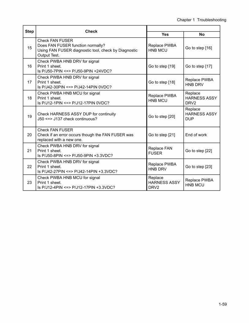
Chapter 1 Troubleshooting
15
Check FAN FUSERDoes FAN FUSER function normally?Using FAN FUSER diagnostic tool, check by Diagnostic Output Test.
Replace PWBA HNB MCU Go to step [16]
16Check PWBA HNB DRV for signalPrint 1 sheet.Is P/J50-7PIN <=> P/J50-9PIN +24VDC?
Go to step [19] Go to step [17]
17Check PWBA HNB DRV for signalPrint 1 sheet.Is P/J42-30PIN <=> P/J42-14PIN 0VDC?
Go to step [18] Replace PWBA HNB DRV
18Check PWBA HNB MCU for signalPrint 1 sheet.Is P/J12-1PIN <=> P/J12-17PIN 0VDC?
Replace PWBA HNB MCU
Replace HARNESS ASSY DRV2
19 Check HARNESS ASSY DUP for continuityJ50 <=> J137 check continuous? Go to step [20]
Replace HARNESS ASSY DUP
20Check FAN FUSERCheck if an error occurs though the FAN FUSER was replaced with a new one.
Go to step [21] End of work
21Check PWBA HNB DRV for signalPrint 1 sheet.Is P/J50-8PIN <=> P/J50-9PIN +3.3VDC?
Replace FAN FUSER Go to step [22]
22Check PWBA HNB DRV for signalPrint 1 sheet.Is P/J42-27PIN <=> P/J42-14PIN +3.3VDC?
Replace PWBA HNB DRV Go to step [23]
23Check PWBA HNB MCU for signalPrint 1 sheet.Is P/J12-4PIN <=> P/J12-17PIN +3.3VDC?
Replace HARNESS ASSY DRV2
Replace PWBA HNB MCU
Step CheckYes No
1-59
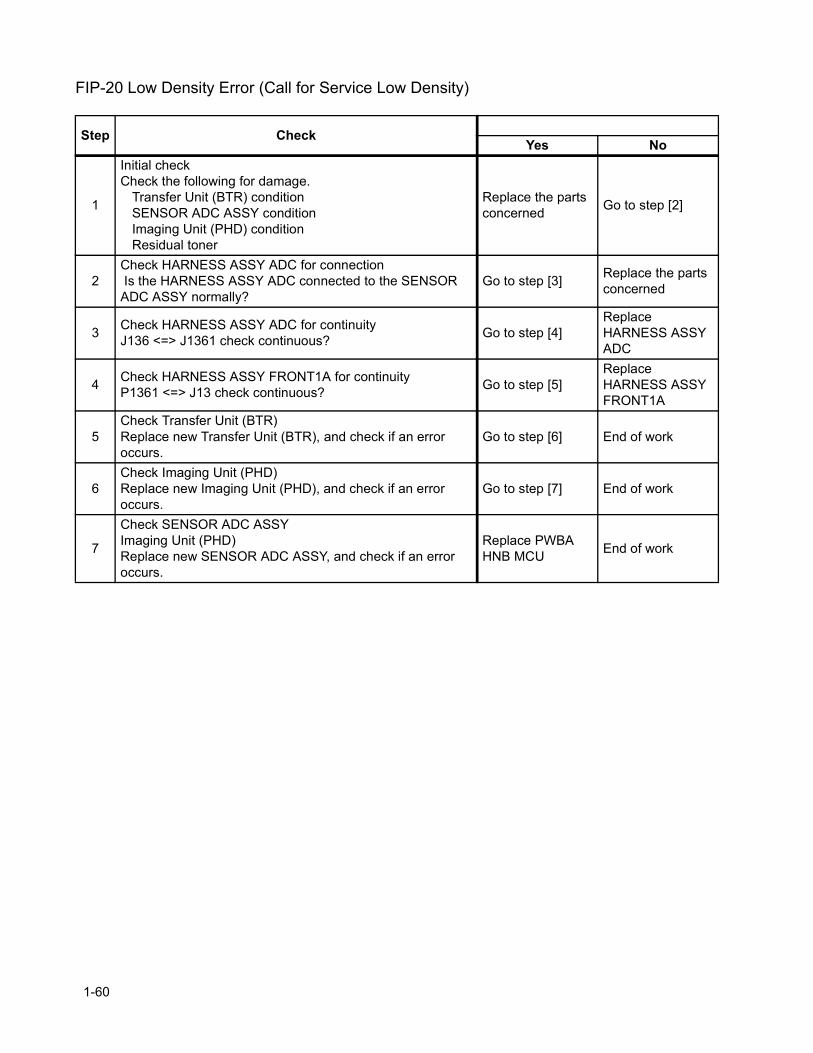
FIP-20 Low Density Error (Call for Service Low Density)
Step CheckYes No
1
Initial checkCheck the following for damage.
Transfer Unit (BTR) conditionSENSOR ADC ASSY conditionImaging Unit (PHD) conditionResidual toner
Replace the parts concerned Go to step [2]
2Check HARNESS ASSY ADC for connection Is the HARNESS ASSY ADC connected to the SENSOR ADC ASSY normally?
Go to step [3] Replace the parts concerned
3 Check HARNESS ASSY ADC for continuityJ136 <=> J1361 check continuous? Go to step [4]
Replace HARNESS ASSY ADC
4 Check HARNESS ASSY FRONT1A for continuityP1361 <=> J13 check continuous? Go to step [5]
Replace HARNESS ASSY FRONT1A
5Check Transfer Unit (BTR)Replace new Transfer Unit (BTR), and check if an error occurs.
Go to step [6] End of work
6Check Imaging Unit (PHD)Replace new Imaging Unit (PHD), and check if an error occurs.
Go to step [7] End of work
7
Check SENSOR ADC ASSYImaging Unit (PHD)Replace new SENSOR ADC ASSY, and check if an error occurs.
Replace PWBA HNB MCU End of work
1-60

Chapter 1 Troubleshooting
FIP-21 Firmware Error (Call for Service Firmware Error)
Step CheckYes No
1 Does an error occur even if the power is turned off and on? Replace PWBA HNB MCU
If the error recurs, replace PWBA HNB MCU
1-61
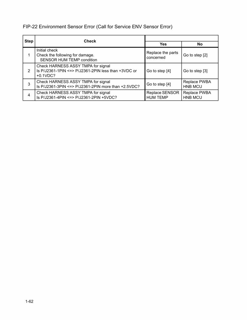
FIP-22 Environment Sensor Error (Call for Service ENV Sensor Error)
Step CheckYes No
1Initial checkCheck the following for damage.
SENSOR HUM TEMP condition
Replace the parts concerned Go to step [2]
2Check HARNESS ASSY TMPA for signalIs P/J2361-1PIN <=> P/J2361-2PIN less than +3VDC or +0.1VDC?
Go to step [4] Go to step [3]
3 Check HARNESS ASSY TMPA for signalIs P/J2361-3PIN <=> P/J2361-2PIN more than +2.5VDC? Go to step [4] Replace PWBA
HNB MCU
4 Check HARNESS ASSY TMPA for signalIs P/J2361-4PIN <=> P/J2361-2PIN +5VDC?
Replace SENSOR HUM TEMP
Replace PWBA HNB MCU
1-62

Chapter 1 Troubleshooting
FIP-23 Yellow Toner Empty (Yellow Toner Low)
Step CheckYes No
1
Initial checkCheck the following for damage.
SENSOR TONER LOW conditionTONER CARTRIDGE conditionTONER MOTOR condition
Replace the parts concerned Go to step [2]
2Check TONER CARTRIDGECheck if an error occurs though the TONER CARTRIDGE was replaced with a new one.
Go to step [3] End of work
3 Check PWBA HNB DRV for signalIs P/J51-16PIN <=> P/J51-15PIN less than +0.2VDC? Go to step [6] Go to step [4]
4 Check HARNESS ASSY TNR for continuityJ441 <=> J51 check continuous? Go to step [5]
Replace HARNESS ASSY TNR
5Check SENSOR TONER LOWCheck if an error occurs though the SENSOR TONER LOW was replaced with a new one.
Go to step [6] End of work
6 Check HARNESS ASSY DRV2 for continuityJ12-23 <=> J42-8 check continuous?
With toolGo to step [7]Without toolGo to step [8]
Replace HARNESS ASSY DRV2
7
Check TONER MOTORDoes TONER MOTOR function normally?Using TONER MOTOR diagnostic tool, check by Diagnostic Output Test.In the test, close the INTERLOCK SW.
Check the toner stirring AUGER or gear for damage
Go to step [8]
8 Check PWBA HNB DRV for signalIs P/J51-1PIN <=> P/J60-2PIN +24VDC? Go to step [9] Replace PWBA
HNB DRV
9 Check HARNESS ASSY TNR for continuityJ511 <=> J51 check continuous? Go to step [10]
Replace HARNESS ASSY TNR
10Check TONER MOTORCheck if an error occurs though the TONER MOTOR was replaced with a new one.
Go to step [11] End of work
11
Check HARNESS ASSY DRV1 for continuityCheck the following for continuity.J11-25 <=> J41-16J11-26 <=> J41-15J11-27 <=> J41-14J11-28 <=> J41-13
Replace PWBA HNB DRV, and if still faulty, replace PWBA HNB MCU
Replace HARNESS ASSY DRV1
1-63
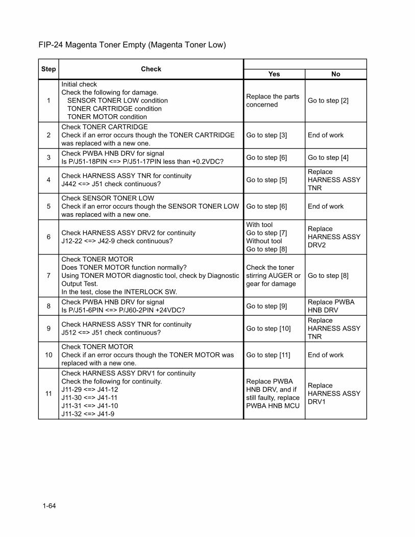
FIP-24 Magenta Toner Empty (Magenta Toner Low)
Step CheckYes No
1
Initial checkCheck the following for damage.
SENSOR TONER LOW conditionTONER CARTRIDGE conditionTONER MOTOR condition
Replace the parts concerned Go to step [2]
2Check TONER CARTRIDGECheck if an error occurs though the TONER CARTRIDGE was replaced with a new one.
Go to step [3] End of work
3 Check PWBA HNB DRV for signalIs P/J51-18PIN <=> P/J51-17PIN less than +0.2VDC? Go to step [6] Go to step [4]
4 Check HARNESS ASSY TNR for continuityJ442 <=> J51 check continuous? Go to step [5]
Replace HARNESS ASSY TNR
5Check SENSOR TONER LOWCheck if an error occurs though the SENSOR TONER LOW was replaced with a new one.
Go to step [6] End of work
6 Check HARNESS ASSY DRV2 for continuityJ12-22 <=> J42-9 check continuous?
With toolGo to step [7]Without toolGo to step [8]
Replace HARNESS ASSY DRV2
7
Check TONER MOTORDoes TONER MOTOR function normally?Using TONER MOTOR diagnostic tool, check by Diagnostic Output Test.In the test, close the INTERLOCK SW.
Check the toner stirring AUGER or gear for damage
Go to step [8]
8 Check PWBA HNB DRV for signalIs P/J51-6PIN <=> P/J60-2PIN +24VDC? Go to step [9] Replace PWBA
HNB DRV
9 Check HARNESS ASSY TNR for continuityJ512 <=> J51 check continuous? Go to step [10]
Replace HARNESS ASSY TNR
10Check TONER MOTORCheck if an error occurs though the TONER MOTOR was replaced with a new one.
Go to step [11] End of work
11
Check HARNESS ASSY DRV1 for continuityCheck the following for continuity.J11-29 <=> J41-12J11-30 <=> J41-11J11-31 <=> J41-10J11-32 <=> J41-9
Replace PWBA HNB DRV, and if still faulty, replace PWBA HNB MCU
Replace HARNESS ASSY DRV1
1-64

Chapter 1 Troubleshooting
FIP-25 Cyan Toner Empty (Cyan Toner Low)
Step CheckYes No
1
Initial checkCheck the following for damage.
SENSOR TONER LOW conditionTONER CARTRIDGE conditionTONER MOTOR condition
Replace the parts concerned Go to step [2]
2Check TONER CARTRIDGECheck if an error occurs though the TONER CARTRIDGE was replaced with a new one.
Go to step [3] End of work
3 Check PWBA HNB DRV for signalIs P/J51-34PIN <=> P/J51-33PIN less than +0.2VDC? Go to step [6] Go to step [4]
4 Check HARNESS ASSY TNR for continuityJ443 <=> J51 check continuous? Go to step [5]
Replace HARNESS ASSY TNR
5Check SENSOR TONER LOWCheck if an error occurs though the SENSOR TONER LOW was replaced with a new one.
Go to step [6] End of work
6 Check HARNESS ASSY DRV2 for continuityJ12-21 <=> J42-10 check continuous?
With toolGo to step [7]Without toolGo to step [8]
Replace HARNESS ASSY DRV2
7
Check TONER MOTORDoes TONER MOTOR function normally?Using TONER MOTOR diagnostic tool, check by Diagnostic Output Test.In the test, close the INTERLOCK SW.
Check the toner stirring AUGER or gear for damage
Go to step [8]
8 Check PWBA HNB DRV for signalIs P/J51-19PIN <=> P/J60-2PIN +24VDC? Go to step [9] Replace PWBA
HNB DRV
9 Check HARNESS ASSY TNR for continuityJ513 <=> J51 check continuous? Go to step [10]
Replace HARNESS ASSY TNR
10Check TONER MOTORCheck if an error occurs though the TONER MOTOR was replaced with a new one.
Go to step [11] End of work
11
Check HARNESS ASSY DRV1 for continuityCheck the following for continuity.J11-33 <=> J41-8J11-34 <=> J41-7J11-35 <=> J41-6J11-36 <=> J41-5
Replace PWBA HNB DRV, and if still faulty, replace PWBA HNB MCU
Replace HARNESS ASSY DRV1
1-65

FIP-26 Black Toner Empty (Black Toner Low)
Step CheckYes No
1
Initial checkCheck the following for damage.
SENSOR TONER LOW conditionTONER CARTRIDGE conditionTONER MOTOR condition
Replace the parts concerned Go to step [2]
2Check TONER CARTRIDGECheck if an error occurs though the TONER CARTRIDGE was the replaced with a new one.
Go to step [3] End of work
3 Check PWBA HNB DRV for signalIs P/J51-36PIN <=> P/J51-35PIN less than +0.2VDC? Go to step [6] Go to step [4]
4 Check HARNESS ASSY TNR for continuityJ444 <=> J51 check continuous? Go to step [5]
Replace HARNESS ASSY TNR
5Check SENSOR TONER LOWCheck if an error occurs though the SENSOR TONER LOW was replaced with a new one.
Go to step [6] End of work
6 Check HARNESS ASSY DRV2 for continuityJ12-24 <=> J42-7 check continuous?
With toolGo to step [7]Without toolGo to step [8]
Replace HARNESS ASSY DRV2
7
Check TONER MOTORDoes TONER MOTOR function normally?Using TONER MOTOR diagnostic tool, check by Diagnostic Output Test.In the test, close the INTERLOCK SW.
Check the toner stirring AUGER or gear for damage
Go to step [8]
8 Check PWBA DRV3 for signalIs P/J51-24PIN <=> P/J60-2PIN +24VDC? Go to step [9] Replace PWBA
HNB DRV
9 Check HARNESS ASSY TNR for continuityJ514 <=> J51 check continuous? Go to step [10]
Replace HARNESS ASSY TNR
10Check TONER MOTORCheck if an error occurs though the TONER MOTOR was replaced with a new one.
Go to step [11] End of work
11
Check HARNESS ASSY DRV1 for continuityCheck the following for continuity.J11-37 <=> J41-4J11-38 <=> J41-3J11-39 <=> J41-2J11-40 <=> J41-1
Replace PWBA HNB DRV, and if still faulty, replace PWBA HNB MCU
Replace HARNESS ASSY DRV1
1-66
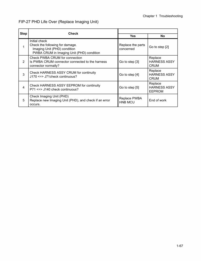
Chapter 1 Troubleshooting
FIP-27 PHD Life Over (Replace Imaging Unit)
Step CheckYes No
1
Initial checkCheck the following for damage.
Imaging Unit (PHD) conditionPWBA CRUM in Imaging Unit (PHD) condition
Replace the parts concerned Go to step [2]
2Check PWBA CRUM for connectionIs PWBA CRUM connector connected to the harness connector normally?
Go to step [3]Replace HARNESS ASSY CRUM
3 Check HARNESS ASSY CRUM for continuityJ170 <=> J71check continuous? Go to step [4]
Replace HARNESS ASSY CRUM
4 Check HARNESS ASSY EEPROM for continuityP71 <=> J140 check continuous? Go to step [5]
Replace HARNESS ASSY EEPROM
5Check Imaging Unit (PHD)Replace new Imaging Unit (PHD), and check if an error occurs.
Replace PWBA HNB MCU End of work
1-67
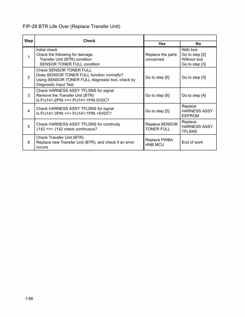
FIP-28 BTR Life Over (Replace Transfer Unit)
Step CheckYes No
1
Initial checkCheck the following for damage.
Transfer Unit (BTR) conditionSENSOR TONER FULL condition
Replace the parts concerned
With toolGo to step [2]Without toolGo to step [3]
2
Check SENSOR TONER FULLDoes SENSOR TONER FULL function normally?Using SENSOR TONER FULL diagnostic tool, check by Diagnostic Input Test.
Go to step [6] Go to step [3]
3Check HARNESS ASSY TFLSNS for signalRemove the Transfer Unit (BTR)Is P/J141-2PIN <=> P/J141-1PIN 0VDC?
Go to step [6] Go to step [4]
4 Check HARNESS ASSY TFLSNS for signalIs P/J141-3PIN <=> P/J141-1PIN +5VDC? Go to step [5]
Replace HARNESS ASSY EEPROM
5 Check HARNESS ASSY TFLSNS for continuityJ142 <=> J142 check continuous?
Replace SENSOR TONER FULL
Replace HARNESS ASSY TFLSNS
6Check Transfer Unit (BTR)Replace new Transfer Unit (BTR), and check if an error occurs
Replace PWBA HNB MCU End of work
1-68

Chapter 1 Troubleshooting
FIP-29 Fuser Life Over (Replace Fuser Unit)
Step CheckYes No
1 Check NVMDoes the error occur even if the Fuser counter is cleared?
Replace PWBA HNB MCU End of work
1-69
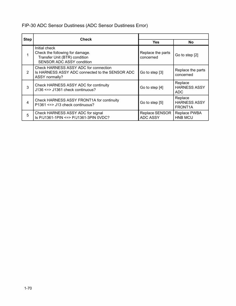
FIP-30 ADC Sensor Dustiness (ADC Sensor Dustiness Error)
Step CheckYes No
1
Initial checkCheck the following for damage.
Transfer Unit (BTR) conditionSENSOR ADC ASSY condition
Replace the parts concerned Go to step [2]
2Check HARNESS ASSY ADC for connectionIs HARNESS ASSY ADC connected to the SENSOR ADC ASSY normally?
Go to step [3] Replace the parts concerned
3 Check HARNESS ASSY ADC for continuityJ136 <=> J1361 check continuous? Go to step [4]
Replace HARNESS ASSY ADC
4 Check HARNESS ASSY FRONT1A for continuityP1361 <=> J13 check continuous? Go to step [5]
Replace HARNESS ASSY FRONT1A
5 Check HARNESS ASSY ADC for signalIs P/J1361-1PIN <=> P/J1361-3PIN 0VDC?
Replace SENSOR ADC ASSY
Replace PWBA HNB MCU
1-70
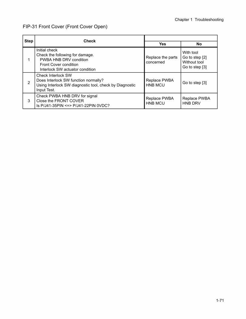
Chapter 1 Troubleshooting
FIP-31 Front Cover (Front Cover Open)
Step CheckYes No
1
Initial checkCheck the following for damage.
PWBA HNB DRV conditionFront Cover conditionInterlock SW actuator condition
Replace the parts concerned
With toolGo to step [2]Without toolGo to step [3]
2
Check Interlock SWDoes Interlock SW function normally?Using Interlock SW diagnostic tool, check by Diagnostic Input Test.
Replace PWBA HNB MCU Go to step [3]
3Check PWBA HNB DRV for signalClose the FRONT COVERIs P/J41-35PIN <=> P/J41-22PIN 0VDC?
Replace PWBA HNB MCU
Replace PWBA HNB DRV
1-71
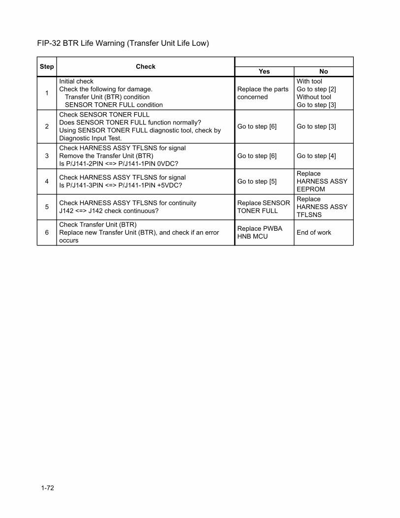
FIP-32 BTR Life Warning (Transfer Unit Life Low)
Step CheckYes No
1
Initial checkCheck the following for damage.
Transfer Unit (BTR) conditionSENSOR TONER FULL condition
Replace the parts concerned
With toolGo to step [2]Without toolGo to step [3]
2
Check SENSOR TONER FULLDoes SENSOR TONER FULL function normally?Using SENSOR TONER FULL diagnostic tool, check by Diagnostic Input Test.
Go to step [6] Go to step [3]
3Check HARNESS ASSY TFLSNS for signalRemove the Transfer Unit (BTR)Is P/J141-2PIN <=> P/J141-1PIN 0VDC?
Go to step [6] Go to step [4]
4 Check HARNESS ASSY TFLSNS for signalIs P/J141-3PIN <=> P/J141-1PIN +5VDC? Go to step [5]
Replace HARNESS ASSY EEPROM
5 Check HARNESS ASSY TFLSNS for continuityJ142 <=> J142 check continuous?
Replace SENSOR TONER FULL
Replace HARNESS ASSY TFLSNS
6Check Transfer Unit (BTR)Replace new Transfer Unit (BTR), and check if an error occurs
Replace PWBA HNB MCU End of work
1-72

Chapter 1 Troubleshooting
FIP-33 Fuser Life Warning (Fuser Life Low)
Step CheckYes No
1 Check NVMDoes the error occur even if the Fuser counter is cleared?
Replace PWBA HNB MCU End of work
1-73
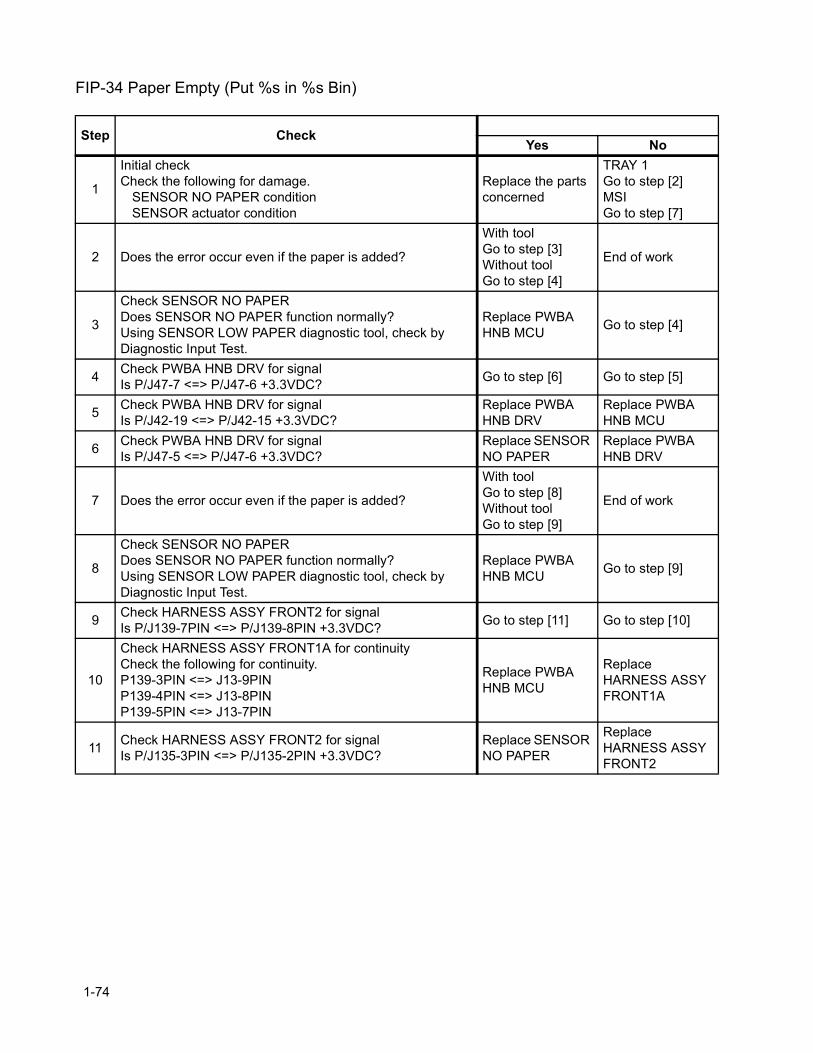
FIP-34 Paper Empty (Put %s in %s Bin)
Step CheckYes No
1
Initial checkCheck the following for damage.
SENSOR NO PAPER conditionSENSOR actuator condition
Replace the parts concerned
TRAY 1Go to step [2]MSIGo to step [7]
2 Does the error occur even if the paper is added?
With toolGo to step [3]Without toolGo to step [4]
End of work
3
Check SENSOR NO PAPERDoes SENSOR NO PAPER function normally?Using SENSOR LOW PAPER diagnostic tool, check by Diagnostic Input Test.
Replace PWBA HNB MCU Go to step [4]
4 Check PWBA HNB DRV for signalIs P/J47-7 <=> P/J47-6 +3.3VDC? Go to step [6] Go to step [5]
5 Check PWBA HNB DRV for signalIs P/J42-19 <=> P/J42-15 +3.3VDC?
Replace PWBA HNB DRV
Replace PWBA HNB MCU
6 Check PWBA HNB DRV for signalIs P/J47-5 <=> P/J47-6 +3.3VDC?
Replace SENSOR NO PAPER
Replace PWBA HNB DRV
7 Does the error occur even if the paper is added?
With toolGo to step [8]Without toolGo to step [9]
End of work
8
Check SENSOR NO PAPERDoes SENSOR NO PAPER function normally?Using SENSOR LOW PAPER diagnostic tool, check by Diagnostic Input Test.
Replace PWBA HNB MCU Go to step [9]
9 Check HARNESS ASSY FRONT2 for signalIs P/J139-7PIN <=> P/J139-8PIN +3.3VDC? Go to step [11] Go to step [10]
10
Check HARNESS ASSY FRONT1A for continuityCheck the following for continuity.P139-3PIN <=> J13-9PINP139-4PIN <=> J13-8PINP139-5PIN <=> J13-7PIN
Replace PWBA HNB MCU
Replace HARNESS ASSY FRONT1A
11 Check HARNESS ASSY FRONT2 for signalIs P/J135-3PIN <=> P/J135-2PIN +3.3VDC?
Replace SENSOR NO PAPER
Replace HARNESS ASSY FRONT2
1-74
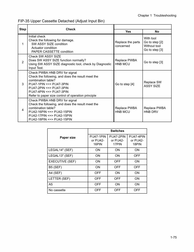
Chapter 1 Troubleshooting
FIP-35 Upper Cassette Detached (Adjust Input Bin)
Step CheckYes No
1
Initial checkCheck the following for damage.
SW ASSY SIZE conditionActuator conditionPAPER CASSETTE condition
Replace the parts concerned
With toolGo to step [2]Without toolGo to step [3]
2
Check SW ASSY SIZEDoes SW ASSY SIZE function normally?Using SW ASSY SIZE diagnostic tool, check by Diagnostic Input Test.
Replace PWBA HNB MCU Go to step [3]
3
Check PWBA HNB DRV for signalCheck the following, and does the result meet the combination table?P/J47-1PIN <=> P/J47-3PINP/J47-2PIN <=> P/J47-3PINP/J47-4PIN <=> P/J47-3PINRefer to paper size control of operation principle
Go to step [4] Replace SW ASSY SIZE
4
Check PWBA HNB DRV for signalCheck the following, and does the result meet the combination table?P/J42-16PIN <=> P/J42-15PINP/J42-17PIN <=> P/J42-15PINP/J42-18PIN <=> P/J42-15PIN
Replace PWBA HNB MCU
Replace PWBA HNB DRV
Paper size
Switches
P/J47-1PIN or P/J42-
16PIN
P/J47-2PIN or P/J42-
17PIN
P/J47-4PIN or P/J42-
18PIN
LEGAL14" (SEF) ON ON ON
LEGAL13" (SEF) ON ON OFF
EXECUTIVE (SEF) ON OFF ON
B5 (SEF) ON OFF OFF
A4 (SEF) OFF ON ON
LETTER (SEF) OFF OFF ON
A5 OFF ON ON
No cassette OFF OFF OFF
1-75
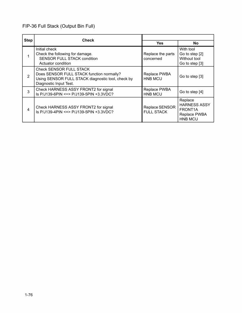
FIP-36 Full Stack (Output Bin Full)
Step CheckYes No
1
Initial checkCheck the following for damage.
SENSOR FULL STACK conditionActuator condition
Replace the parts concerned
With toolGo to step [2]Without toolGo to step [3]
2
Check SENSOR FULL STACKDoes SENSOR FULL STACK function normally?Using SENSOR FULL STACK diagnostic tool, check by Diagnostic Input Test.
Replace PWBA HNB MCU Go to step [3]
3 Check HARNESS ASSY FRONT2 for signalIs P/J139-6PIN <=> P/J139-5PIN +3.3VDC?
Replace PWBA HNB MCU Go to step [4]
4 Check HARNESS ASSY FRONT2 for signalIs P/J139-4PIN <=> P/J139-5PIN +3.3VDC?
Replace SENSOR FULL STACK
Replace HARNESS ASSY FRONT1AReplace PWBA HNB MCU
1-76
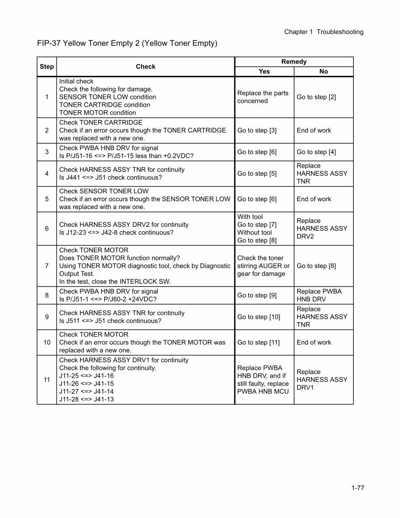
Chapter 1 Troubleshooting
FIP-37 Yellow Toner Empty 2 (Yellow Toner Empty)
Step CheckRemedy
Yes No
1
Initial checkCheck the following for damage.SENSOR TONER LOW conditionTONER CARTRIDGE conditionTONER MOTOR condition
Replace the parts concerned Go to step [2]
2Check TONER CARTRIDGECheck if an error occurs though the TONER CARTRIDGE was replaced with a new one.
Go to step [3] End of work
3 Check PWBA HNB DRV for signalIs P/J51-16 <=> P/J51-15 less than +0.2VDC? Go to step [6] Go to step [4]
4 Check HARNESS ASSY TNR for continuityIs J441 <=> J51 check continuous? Go to step [5]
Replace HARNESS ASSY TNR
5Check SENSOR TONER LOWCheck if an error occurs though the SENSOR TONER LOW was replaced with a new one.
Go to step [6] End of work
6 Check HARNESS ASSY DRV2 for continuityIs J12-23 <=> J42-8 check continuous?
With toolGo to step [7]Without toolGo to step [8]
Replace HARNESS ASSY DRV2
7
Check TONER MOTORDoes TONER MOTOR function normally?Using TONER MOTOR diagnostic tool, check by Diagnostic Output Test.In the test, close the INTERLOCK SW.
Check the toner stirring AUGER or gear for damage
Go to step [8]
8 Check PWBA HNB DRV for signalIs P/J51-1 <=> P/J60-2 +24VDC? Go to step [9] Replace PWBA
HNB DRV
9 Check HARNESS ASSY TNR for continuityIs J511 <=> J51 check continuous? Go to step [10]
Replace HARNESS ASSY TNR
10Check TONER MOTORCheck if an error occurs though the TONER MOTOR was replaced with a new one.
Go to step [11] End of work
11
Check HARNESS ASSY DRV1 for continuityCheck the following for continuity.J11-25 <=> J41-16J11-26 <=> J41-15J11-27 <=> J41-14J11-28 <=> J41-13
Replace PWBA HNB DRV, and if still faulty, replace PWBA HNB MCU
Replace HARNESS ASSY DRV1
1-77
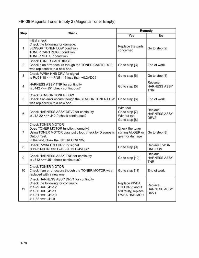
FIP-38 Magenta Toner Empty 2 (Magenta Toner Empty)
Step CheckRemedy
Yes No
1
Initial checkCheck the following for damage.SENSOR TONER LOW conditionTONER CARTRIDGE conditionTONER MOTOR condition
Replace the parts concerned Go to step [2]
2Check TONER CARTRIDGECheck if an error occurs though the TONER CARTRIDGE was replaced with a new one.
Go to step [3] End of work
3 Check PWBA HNB DRV for signalIs P/J51-18 <=> P/J51-17 less than +0.2VDC? Go to step [6] Go to step [4]
4 HARNESS ASSY TNR for continuityIs J442 <=> J51 check continuous? Go to step [5]
Replace HARNESS ASSY TNR
5Check SENSOR TONER LOWCheck if an error occurs though the SENSOR TONER LOW was replaced with a new one.
Go to step [6] End of work
6 Check HARNESS ASSY DRV2 for continuityIs J12-22 <=> J42-9 check continuous?
With toolGo to step [7]Without toolGo to step [8]
Replace HARNESS ASSY DRV2
7
Check TONER MOTORDoes TONER MOTOR function normally?Using TONER MOTOR diagnostic tool, check by Diagnostic Output Test.In the test, close the INTERLOCK SW.
Check the toner stirring AUGER or gear for damage
Go to step [8]
8 Check PWBA HNB DRV for signalIs P/J51-6PIN <=> P/J60-2PIN +24VDC? Go to step [9] Replace PWBA
HNB DRV
9 Check HARNESS ASSY TNR for continuityIs J512 <=> J51 check continuous? Go to step [10]
Replace HARNESS ASSY TNR
10Check TONER MOTORCheck if an error occurs though the TONER MOTOR was replaced with a new one.
Go to step [11] End of work
11
Check HARNESS ASSY DRV1 for continuityCheck the following for continuity.J11-29 <=> J41-12J11-30 <=> J41-11J11-31 <=> J41-10J11-32 <=> J41-9
Replace PWBA HNB DRV, and if still faulty, replace PWBA HNB MCU
Replace HARNESS ASSY DRV1
1-78
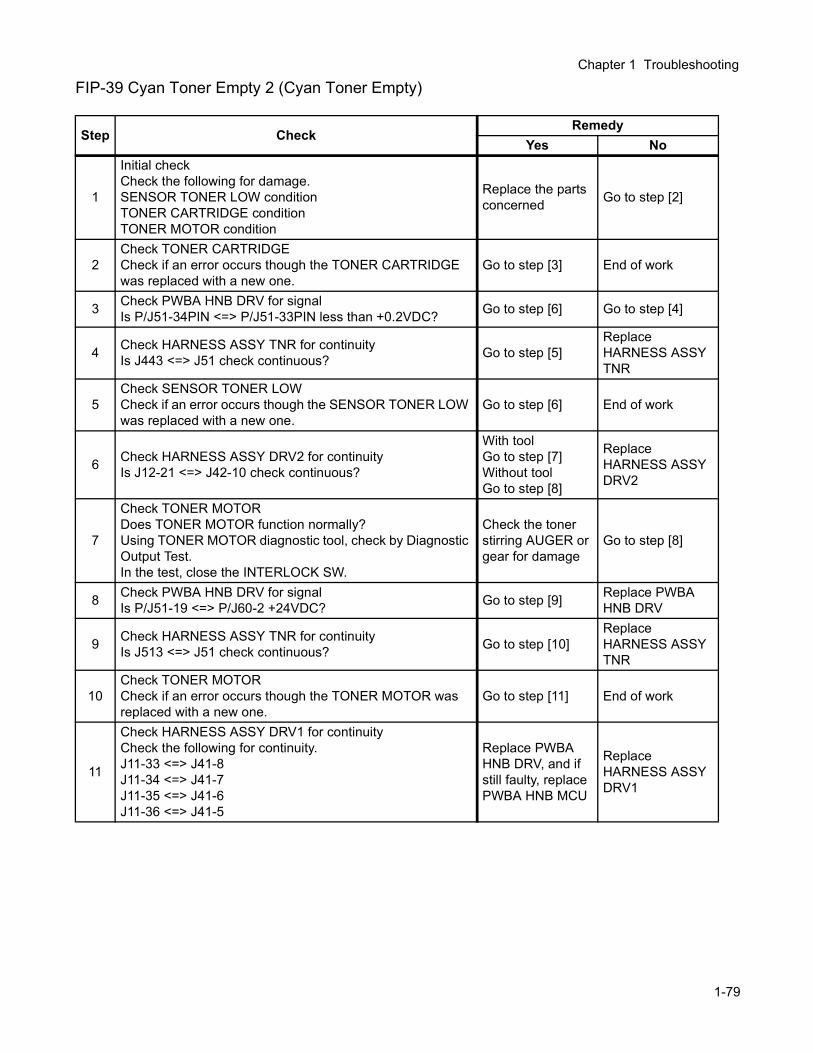
Chapter 1 Troubleshooting
FIP-39 Cyan Toner Empty 2 (Cyan Toner Empty)
Step CheckRemedy
Yes No
1
Initial checkCheck the following for damage.SENSOR TONER LOW conditionTONER CARTRIDGE conditionTONER MOTOR condition
Replace the parts concerned Go to step [2]
2Check TONER CARTRIDGECheck if an error occurs though the TONER CARTRIDGE was replaced with a new one.
Go to step [3] End of work
3 Check PWBA HNB DRV for signalIs P/J51-34PIN <=> P/J51-33PIN less than +0.2VDC? Go to step [6] Go to step [4]
4 Check HARNESS ASSY TNR for continuityIs J443 <=> J51 check continuous? Go to step [5]
Replace HARNESS ASSY TNR
5Check SENSOR TONER LOWCheck if an error occurs though the SENSOR TONER LOW was replaced with a new one.
Go to step [6] End of work
6 Check HARNESS ASSY DRV2 for continuityIs J12-21 <=> J42-10 check continuous?
With toolGo to step [7]Without toolGo to step [8]
Replace HARNESS ASSY DRV2
7
Check TONER MOTORDoes TONER MOTOR function normally?Using TONER MOTOR diagnostic tool, check by Diagnostic Output Test.In the test, close the INTERLOCK SW.
Check the toner stirring AUGER or gear for damage
Go to step [8]
8 Check PWBA HNB DRV for signalIs P/J51-19 <=> P/J60-2 +24VDC? Go to step [9] Replace PWBA
HNB DRV
9 Check HARNESS ASSY TNR for continuityIs J513 <=> J51 check continuous? Go to step [10]
Replace HARNESS ASSY TNR
10Check TONER MOTORCheck if an error occurs though the TONER MOTOR was replaced with a new one.
Go to step [11] End of work
11
Check HARNESS ASSY DRV1 for continuityCheck the following for continuity.J11-33 <=> J41-8J11-34 <=> J41-7J11-35 <=> J41-6J11-36 <=> J41-5
Replace PWBA HNB DRV, and if still faulty, replace PWBA HNB MCU
Replace HARNESS ASSY DRV1
1-79

FIP-40 Black Toner Empty 2 (Black Toner Empty)
Step CheckRemedy
Yes No
1
Initial checkCheck the following for damage.SENSOR TONER LOW conditionTONER CARTRIDGE conditionTONER MOTOR condition
Replace the parts concerned Go to step [2]
2Check TONER CARTRIDGECheck if an error occurs though the TONER CARTRIDGE was replaced with a new one.
Go to step [3] End of work
3 Check PWBA HNB DRV for signalIs P/J51-36 <=> P/J51-35 less than +0.2VDC? Go to step [6] Go to step [4]
4 Check HARNESS ASSY TNR for continuityIs J444 <=> J51 check continuous? Go to step [5]
Replace HARNESS ASSY TNR
5Check SENSOR TONER LOWCheck if an error occurs though the SENSOR TONER LOW was replaced with a new one.
Go to step [6] End of work
6 Check HARNESS ASSY DRV2 for continuityIs J12-24 <=> J42-7 check continuous?
With toolGo to step [7]Without toolGo to step [8]
Replace HARNESS ASSY DRV2
7
Check TONER MOTORDoes TONER MOTOR function normally?Using TONER MOTOR diagnostic tool, check by Diagnostic Output Test.In the test, close the INTERLOCK SW.
Check the toner stirring AUGER or gear for damage
Go to step [8]
8 Check PWBA DRV3 for signalIs P/J51-24 <=> P/J60-2 +24VDC? Go to step [9] Replace PWBA
HNB DRV
9 Check HARNESS ASSY TNR for continuityIs J514 <=> J51 check continuous? Go to step [10]
Replace HARNESS ASSY TNR
10Check TONER MOTORCheck if an error occurs though the TONER MOTOR was replaced with a new one.
Go to step [11] End of work
11
Check HARNESS ASSY DRV1 for continuityCheck the following for continuity.J11-37 <=> J41-4J11-38 <=> J41-3J11-39 <=> J41-2J11-40 <=> J41-1
Replace PWBA HNB DRV, and if still faulty, replace PWBA HNB MCU
Replace HARNESS ASSY DRV1
1-80
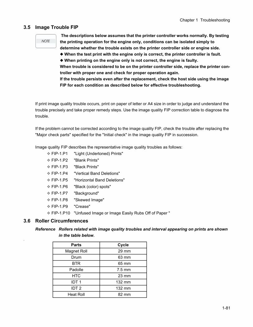
Chapter 1 Troubleshooting
3.5 Image Trouble FIP The descriptions below assumes that the printer controller works normally. By testing the printing operation for the engine only, conditions can be isolated simply to determine whether the trouble exists on the printer controller side or engine side. When the test print with the engine only is correct, the printer controller is fault. When printing on the engine only is not correct, the engine is faulty.When trouble is considered to be on the printer controller side, replace the printer con-troller with proper one and check for proper operation again.If the trouble persists even after the replacement, check the host side using the image FIP for each condition as described below for effective troubleshooting.
If print image quality trouble occurs, print on paper of letter or A4 size in order to judge and understand the trouble precisely and take proper remedy steps. Use the image quality FIP correction table to diagnose the trouble.
If the problem cannot be corrected according to the image quality FIP, check the trouble after replacing the "Major check parts" specified for the "Initial check" in the image quality FIP in succession.
Image quality FIP describes the representative image quality troubles as follows: FIP-1.P1 "Light (Undertoned) Prints" FIP-1.P2 "Blank Prints" FIP-1.P3 "Black Prints" FIP-1.P4 "Vertical Band Deletions" FIP-1.P5 "Horizontal Band Deletions" FIP-1.P6 "Black (color) spots" FIP-1.P7 "Background" FIP-1.P8 "Skewed Image" FIP-1.P9 "Crease" FIP-1.P10 "Unfused Image or Image Easily Rubs Off of Paper "
3.6 Roller CircumferencesReference Rollers related with image quality troubles and interval appearing on prints are shown
in the table below.ÅB
Parts CycleMagnet Roll 29 mm
Drum 63 mmBTR 65 mm
Padolle 7.5 mmHTC 23 mmIDT 1 132 mmIDT 2 132 mm
Heat Roll 82 mm
1-81
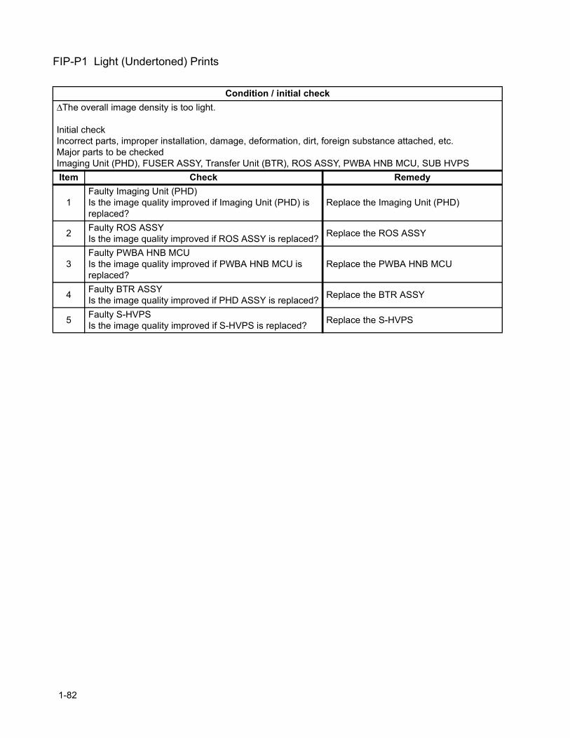
FIP-P1 Light (Undertoned) Prints
Condition / initial check∆The overall image density is too light.
Initial checkIncorrect parts, improper installation, damage, deformation, dirt, foreign substance attached, etc.Major parts to be checkedImaging Unit (PHD), FUSER ASSY, Transfer Unit (BTR), ROS ASSY, PWBA HNB MCU, SUB HVPSItem Check Remedy
1Faulty Imaging Unit (PHD)Is the image quality improved if Imaging Unit (PHD) is replaced?
Replace the Imaging Unit (PHD)
2 Faulty ROS ASSYIs the image quality improved if ROS ASSY is replaced? Replace the ROS ASSY
3Faulty PWBA HNB MCUIs the image quality improved if PWBA HNB MCU is replaced?
Replace the PWBA HNB MCU
4 Faulty BTR ASSYIs the image quality improved if PHD ASSY is replaced? Replace the BTR ASSY
5 Faulty S-HVPSIs the image quality improved if S-HVPS is replaced? Replace the S-HVPS
1-82
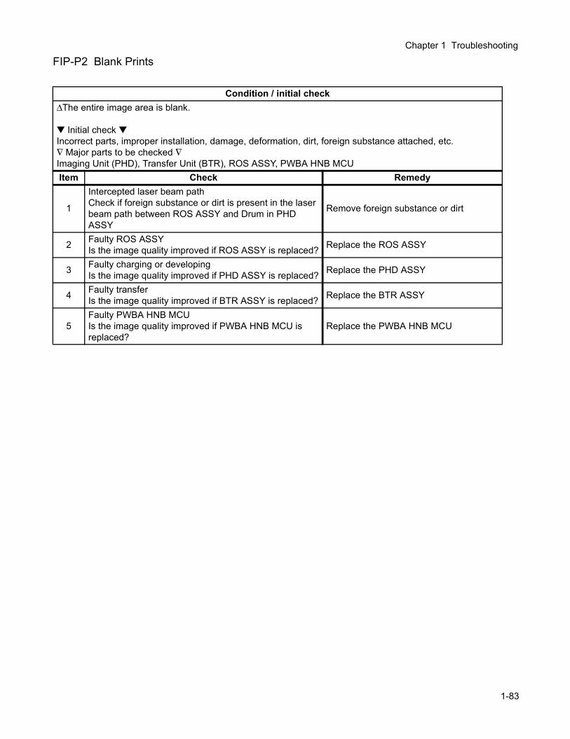
Chapter 1 Troubleshooting
FIP-P2 Blank Prints
Condition / initial check∆The entire image area is blank.
Initial check Incorrect parts, improper installation, damage, deformation, dirt, foreign substance attached, etc.∇ Major parts to be checked ∇Imaging Unit (PHD), Transfer Unit (BTR), ROS ASSY, PWBA HNB MCUItem Check Remedy
1
Intercepted laser beam pathCheck if foreign substance or dirt is present in the laser beam path between ROS ASSY and Drum in PHD ASSY
Remove foreign substance or dirt
2 Faulty ROS ASSYIs the image quality improved if ROS ASSY is replaced? Replace the ROS ASSY
3 Faulty charging or developingIs the image quality improved if PHD ASSY is replaced? Replace the PHD ASSY
4 Faulty transferIs the image quality improved if BTR ASSY is replaced? Replace the BTR ASSY
5Faulty PWBA HNB MCUIs the image quality improved if PWBA HNB MCU is replaced?
Replace the PWBA HNB MCU
1-83
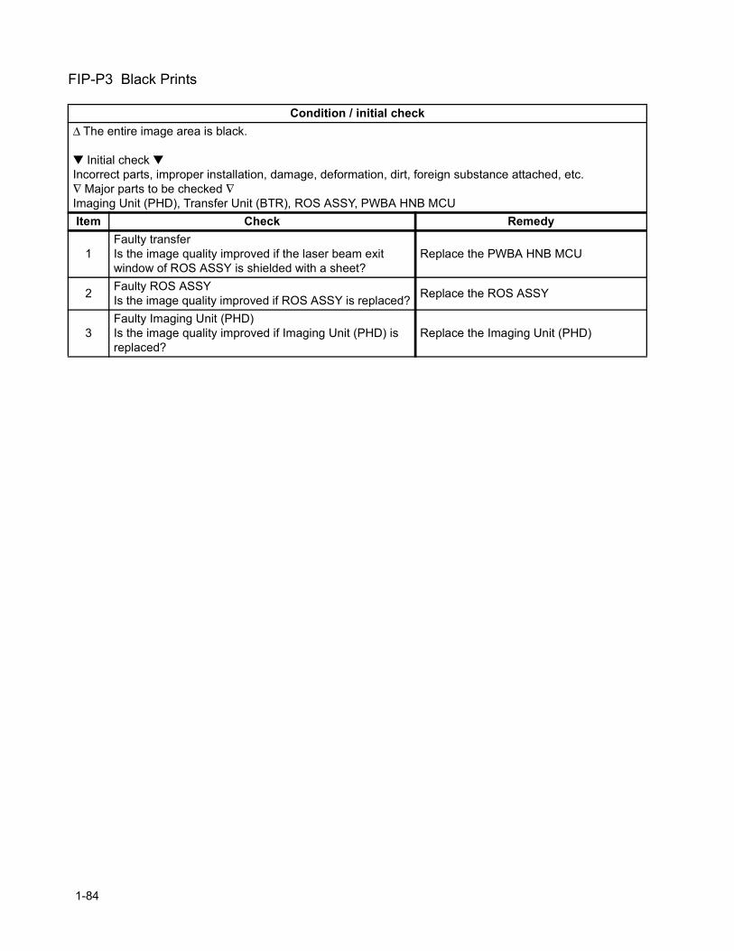
FIP-P3 Black Prints
Condition / initial check∆ The entire image area is black.
Initial check Incorrect parts, improper installation, damage, deformation, dirt, foreign substance attached, etc.∇ Major parts to be checked ∇Imaging Unit (PHD), Transfer Unit (BTR), ROS ASSY, PWBA HNB MCUItem Check Remedy
1Faulty transferIs the image quality improved if the laser beam exit window of ROS ASSY is shielded with a sheet?
Replace the PWBA HNB MCU
2 Faulty ROS ASSYIs the image quality improved if ROS ASSY is replaced? Replace the ROS ASSY
3Faulty Imaging Unit (PHD)Is the image quality improved if Imaging Unit (PHD) is replaced?
Replace the Imaging Unit (PHD)
1-84
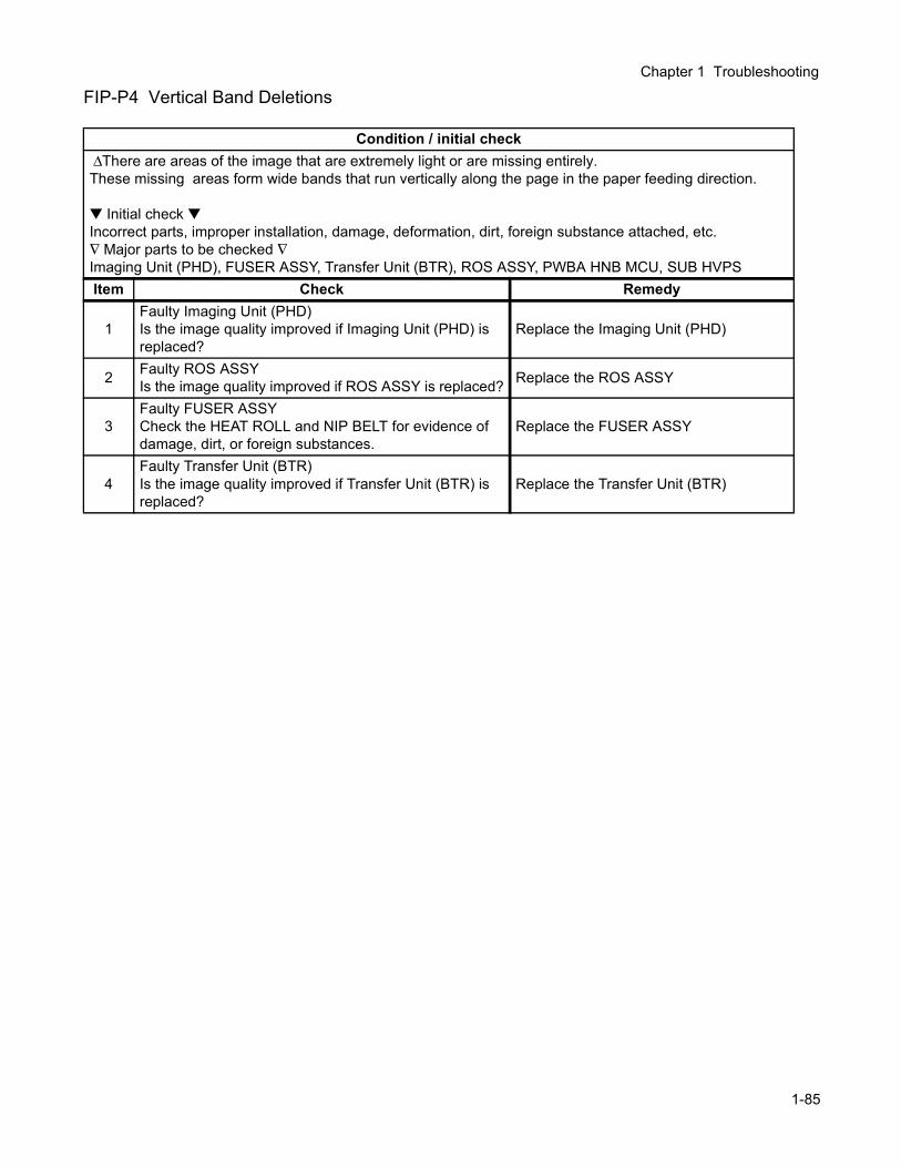
Chapter 1 Troubleshooting
FIP-P4 Vertical Band Deletions
Condition / initial check ∆There are areas of the image that are extremely light or are missing entirely.These missing areas form wide bands that run vertically along the page in the paper feeding direction.
Initial check Incorrect parts, improper installation, damage, deformation, dirt, foreign substance attached, etc.∇ Major parts to be checked ∇Imaging Unit (PHD), FUSER ASSY, Transfer Unit (BTR), ROS ASSY, PWBA HNB MCU, SUB HVPSItem Check Remedy
1Faulty Imaging Unit (PHD)Is the image quality improved if Imaging Unit (PHD) is replaced?
Replace the Imaging Unit (PHD)
2 Faulty ROS ASSYIs the image quality improved if ROS ASSY is replaced? Replace the ROS ASSY
3Faulty FUSER ASSYCheck the HEAT ROLL and NIP BELT for evidence of damage, dirt, or foreign substances.
Replace the FUSER ASSY
4Faulty Transfer Unit (BTR)Is the image quality improved if Transfer Unit (BTR) is replaced?
Replace the Transfer Unit (BTR)
1-85
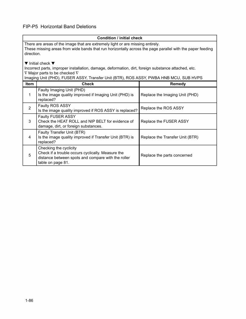
FIP-P5 Horizontal Band Deletions
Condition / initial checkThere are areas of the image that are extremely light or are missing entirely.These missing areas from wide bands that run horizontally across the page parallel with the paper feeding direction.
Initial check Incorrect parts, improper installation, damage, deformation, dirt, foreign substance attached, etc.∇ Major parts to be checked ∇Imaging Unit (PHD), FUSER ASSY, Transfer Unit (BTR), ROS ASSY, PWBA HNB MCU, SUB HVPSItem Check Remedy
1Faulty Imaging Unit (PHD)Is the image quality improved if Imaging Unit (PHD) is replaced?
Replace the Imaging Unit (PHD)
2 Faulty ROS ASSYIs the image quality improved if ROS ASSY is replaced? Replace the ROS ASSY
3Faulty FUSER ASSYCheck the HEAT ROLL and NIP BELT for evidence of damage, dirt, or foreign substances.
Replace the FUSER ASSY
4Faulty Transfer Unit (BTR)Is the image quality improved if Transfer Unit (BTR) is replaced?
Replace the Transfer Unit (BTR)
5
Checking the cyclicityCheck if a trouble occurs cyclically. Measure the distance between spots and compare with the roller table on page 81.
Replace the parts concerned
1-86
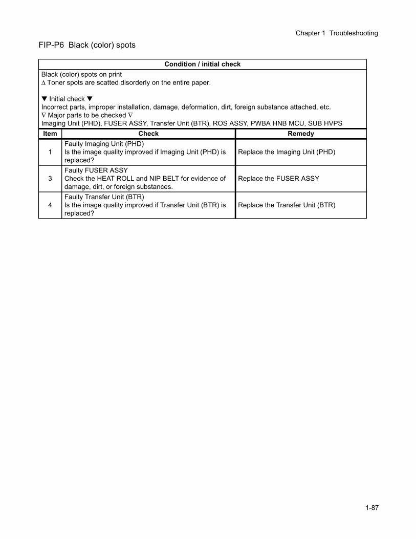
Chapter 1 Troubleshooting
FIP-P6 Black (color) spots
Condition / initial checkBlack (color) spots on print∆ Toner spots are scatted disorderly on the entire paper.
Initial check Incorrect parts, improper installation, damage, deformation, dirt, foreign substance attached, etc.∇ Major parts to be checked ∇Imaging Unit (PHD), FUSER ASSY, Transfer Unit (BTR), ROS ASSY, PWBA HNB MCU, SUB HVPSItem Check Remedy
1Faulty Imaging Unit (PHD)Is the image quality improved if Imaging Unit (PHD) is replaced?
Replace the Imaging Unit (PHD)
3Faulty FUSER ASSYCheck the HEAT ROLL and NIP BELT for evidence of damage, dirt, or foreign substances.
Replace the FUSER ASSY
4Faulty Transfer Unit (BTR)Is the image quality improved if Transfer Unit (BTR) is replaced?
Replace the Transfer Unit (BTR)
1-87
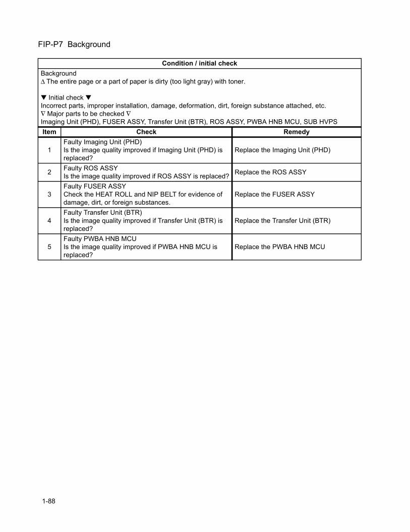
FIP-P7 Background
Condition / initial checkBackground∆ The entire page or a part of paper is dirty (too light gray) with toner.
Initial check Incorrect parts, improper installation, damage, deformation, dirt, foreign substance attached, etc.∇ Major parts to be checked ∇Imaging Unit (PHD), FUSER ASSY, Transfer Unit (BTR), ROS ASSY, PWBA HNB MCU, SUB HVPSItem Check Remedy
1Faulty Imaging Unit (PHD)Is the image quality improved if Imaging Unit (PHD) is replaced?
Replace the Imaging Unit (PHD)
2 Faulty ROS ASSYIs the image quality improved if ROS ASSY is replaced? Replace the ROS ASSY
3Faulty FUSER ASSYCheck the HEAT ROLL and NIP BELT for evidence of damage, dirt, or foreign substances.
Replace the FUSER ASSY
4Faulty Transfer Unit (BTR)Is the image quality improved if Transfer Unit (BTR) is replaced?
Replace the Transfer Unit (BTR)
5Faulty PWBA HNB MCUIs the image quality improved if PWBA HNB MCU is replaced?
Replace the PWBA HNB MCU
1-88
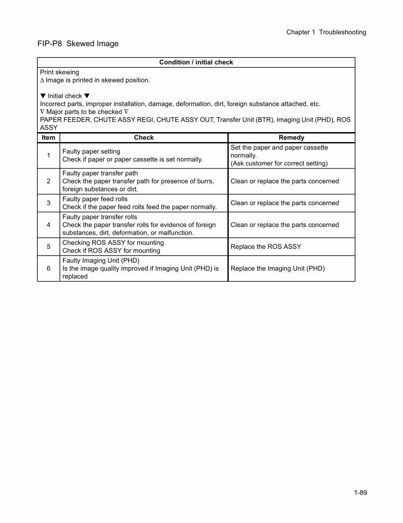
Chapter 1 Troubleshooting
FIP-P8 Skewed Image
Condition / initial checkPrint skewing∆ Image is printed in skewed position.
Initial check Incorrect parts, improper installation, damage, deformation, dirt, foreign substance attached, etc.∇ Major parts to be checked ∇PAPER FEEDER, CHUTE ASSY REGI, CHUTE ASSY OUT, Transfer Unit (BTR), Imaging Unit (PHD), ROS ASSYItem Check Remedy
1 Faulty paper settingCheck if paper or paper cassette is set normally.
Set the paper and paper cassette normally. (Ask customer for correct setting)
2Faulty paper transfer pathCheck the paper transfer path for presence of burrs, foreign substances or dirt.
Clean or replace the parts concerned
3 Faulty paper feed rollsCheck if the paper feed rolls feed the paper normally. Clean or replace the parts concerned
4Faulty paper transfer rollsCheck the paper transfer rolls for evidence of foreign substances, dirt, deformation, or malfunction.
Clean or replace the parts concerned
5 Checking ROS ASSY for mountingCheck if ROS ASSY for mounting Replace the ROS ASSY
6Faulty Imaging Unit (PHD)Is the image quality improved if Imaging Unit (PHD) is replaced
Replace the Imaging Unit (PHD)
1-89
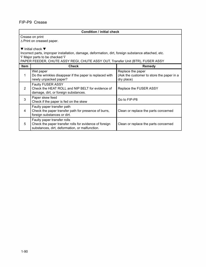
FIP-P9 Crease
Condition / initial checkCrease on print∆ Print on creased paper.
Initial check Incorrect parts, improper installation, damage, deformation, dirt, foreign substance attached, etc.∇ Major parts to be checked ∇PAPER FEEDER, CHUTE ASSY REGI, CHUTE ASSY OUT, Transfer Unit (BTR), FUSER ASSYItem Check Remedy
1Wet paperDo the wrinkles disappear if the paper is replaced with newly unpacked paper?
Replace the paper(Ask the customer to store the paper in a dry place)
2Faulty FUSER ASSYCheck the HEAT ROLL and NIP BELT for evidence of damage, dirt, or foreign substances.
Replace the FUSER ASSY
3 Paper skew feedCheck if the paper is fed on the skew Go to FIP-P8
4Faulty paper transfer pathCheck the paper transfer path for presence of burrs, foreign substances or dirt.
Clean or replace the parts concerned
5Faulty paper transfer rollsCheck the paper transfer rolls for evidence of foreign substances, dirt, deformation, or malfunction.
Clean or replace the parts concerned
1-90
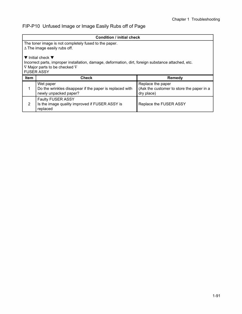
Chapter 1 Troubleshooting
FIP-P10 Unfused Image or Image Easily Rubs off of Page
Condition / initial checkThe toner image is not completely fused to the paper.∆ The image easily rubs off.
Initial check Incorrect parts, improper installation, damage, deformation, dirt, foreign substance attached, etc.∇ Major parts to be checked ∇FUSER ASSYItem Check Remedy
1Wet paperDo the wrinkles disappear if the paper is replaced with newly unpacked paper?
Replace the paper(Ask the customer to store the paper in a dry place)
2Faulty FUSER ASSYIs the image quality improved if FUSER ASSY is replaced
Replace the FUSER ASSY
1-91
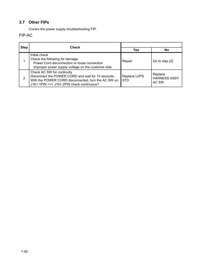
3.7 Other FIPsCovers the power supply troubleshooting FIP.
FIP-AC
Step CheckYes No
1
Initial checkCheck the following for damage.
Power Cord disconnection or loose connectionImproper power supply voltage on the customer side
Repair Go to step [2]
2
Check AC SW for continuityDisconnect the POWER CORD and wait for 10 seconds.With the POWER CORD disconnected, turn the AC SW on.J161-1PIN <=> J161-2PIN check continuous?
Replace LVPS STD
Replace HARNESS ASSY AC SW
1-92
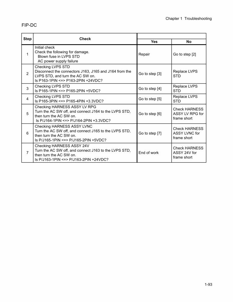
Chapter 1 Troubleshooting
FIP-DC
Step CheckYes No
1
Initial checkCheck the following for damage.
Blown fuse in LVPS STDAC power supply failure
Repair Go to step [2]
2
Checking LVPS STDDisconnect the connectors J163, J165 and J164 from the LVPS STD, and turn the AC SW on.Is P163-1PIN <=> P163-2PIN +24VDC?
Go to step [3] Replace LVPS STD
3 Checking LVPS STDIs P165-1PIN <=> P165-2PIN +5VDC? Go to step [4] Replace LVPS
STD
4 Checking LVPS STDIs P165-3PIN <=> P165-4PIN +3.3VDC? Go to step [5] Replace LVPS
STD
5
Checking HARNESS ASSY LV RPGTurn the AC SW off, and connect J164 to the LVPS STD, then turn the AC SW on. Is P/J164-1PIN <=> P/J164-2PIN +3.3VDC?
Go to step [6]Check HARNESS ASSY LV RPG for frame short
6
Checking HARNESS ASSY LVNCTurn the AC SW off, and connect J165 to the LVPS STD, then turn the AC SW on.Is P/J165-1PIN <=> P/J165-2PIN +5VDC?
Go to step [7]Check HARNESS ASSY LVNC for frame short
7
Checking HARNESS ASSY 24VTurn the AC SW off, and connect J163 to the LVPS STD, then turn the AC SW on.Is P/J163-1PIN <=> P/J163-2PIN +24VDC?
End of workCheck HARNESS ASSY 24V for frame short
1-93
4. Preventive MaintenanceWhen you visit a customer, perform preventive maintenance services irrespective of the major object of your visit to prevent possible troubles beforehand.
Preventive maintenance procedure1) Ask the customer how the laser printer is used.2) Record the accumulated number of sheets printed.
Replace the parts to be replaced periodically based on the number of prints. If required, replace such parts at this time.
3) Print on several sheets of paper to check for proper operation.4) Remove foreign substances on the Transfer Unit (BTR), Imaging Unit (PHD), FUSER ASSY and paper
delivery rolls and clean stains with a brush or dry cloth.If stain is serious, clean with wet cloth and then dry cloth. Be careful not to damage the parts at this time.
5) Cleaning of fan exhaust portRemove the FRONT HEAD COVER and clean the FUSER FAN to remove dust deposited on it with a brush. Remove the REAR COVER and clean the dust deposit on the fan.
If the exhaust port or fan is clogged, temperature in this laser printer increases causing trouble.
6) Print on several sheets again to check for proper operation.
1-94

Chapter 2 Operation of Diagnostics

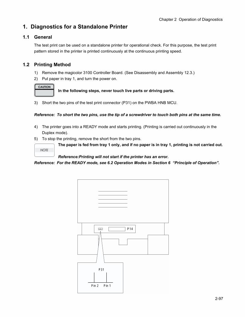
Chapter 2 Operation of Diagnostics
1. Diagnostics for a Standalone Printer
1.1 GeneralThe test print can be used on a standalone printer for operational check. For this purpose, the test print pattern stored in the printer is printed continuously at the continuous printing speed.
1.2 Printing Method1) Remove the magicolor 3100 Controller Board. (See Disassembly and Assembly 12.3.)2) Put paper in tray 1, and turn the power on.
In the following steps, never touch live parts or driving parts.
3) Short the two pins of the test print connector (P31) on the PWBA HNB MCU.
Reference: To short the two pins, use the tip of a screwdriver to touch both pins at the same time.
4) The printer goes into a READY mode and starts printing. (Printing is carried out continuously in the Duplex mode).
5) To stop the printing, remove the short from the two pins.The paper is fed from tray 1 only, and if no paper is in tray 1, printing is not carried out.
Reference:Printing will not start if the printer has an error.Reference: For the READY mode, see 6.2 Operation Modes in Section 6 “Principle of Operation”.
P31
Pin 2 Pin 1
P14
2-97
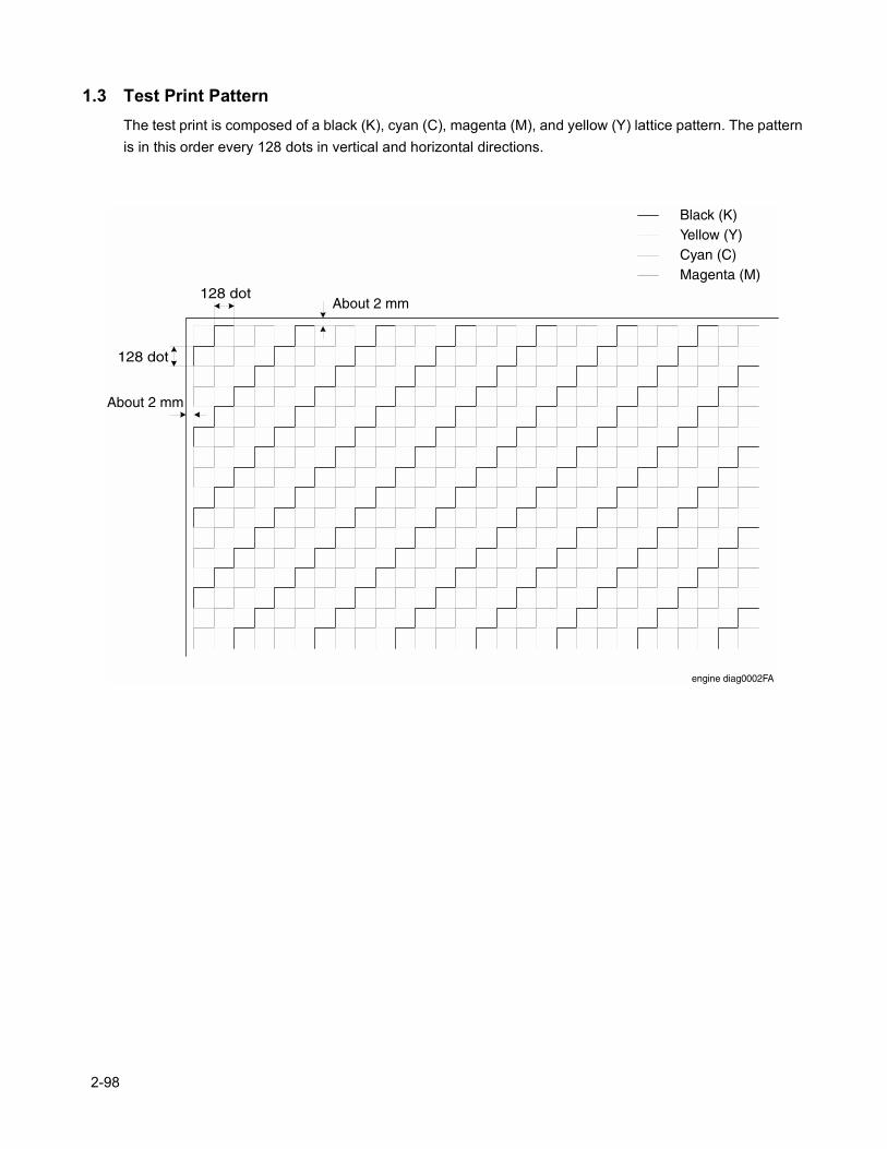
1.3 Test Print PatternThe test print is composed of a black (K), cyan (C), magenta (M), and yellow (Y) lattice pattern. The pattern is in this order every 128 dots in vertical and horizontal directions.
engine diag0002FA
Black (K)Yellow (Y)Cyan (C)Magenta (M)
128 dot
128 dot
About 2 mm
About 2 mm
2-98
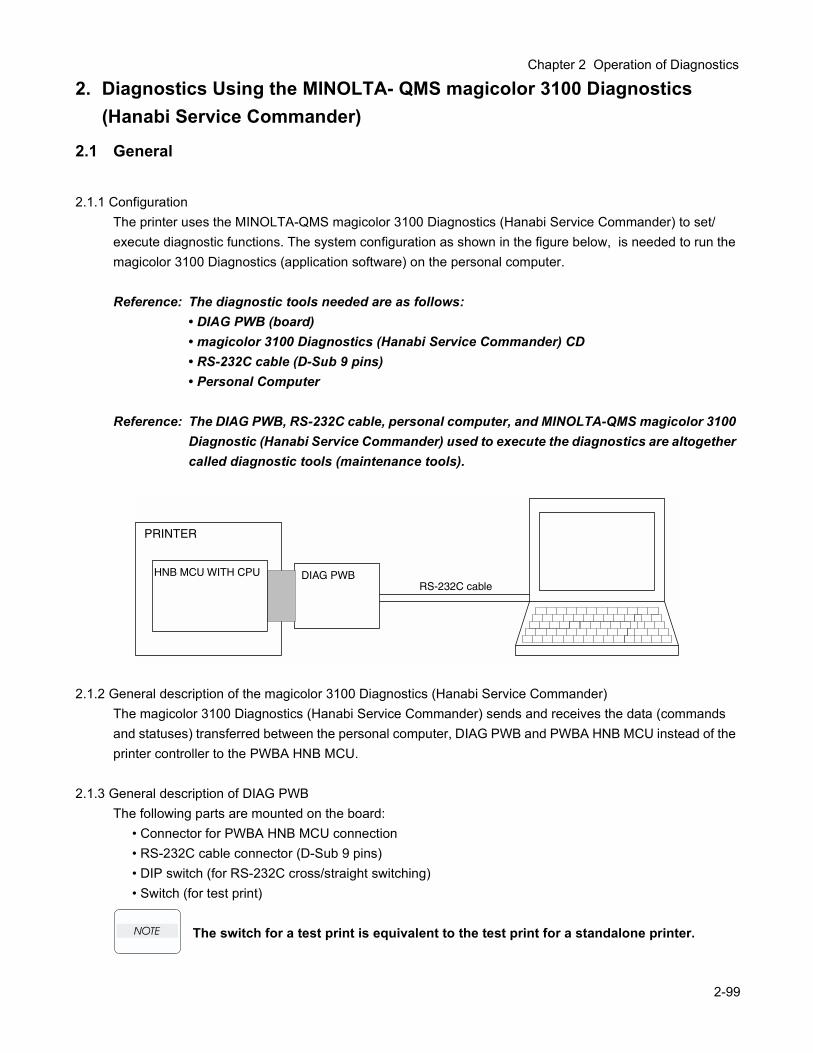
Chapter 2 Operation of Diagnostics
2. Diagnostics Using the MINOLTA- QMS magicolor 3100 Diagnostics (Hanabi Service Commander)
2.1 General
2.1.1 ConfigurationThe printer uses the MINOLTA-QMS magicolor 3100 Diagnostics (Hanabi Service Commander) to set/execute diagnostic functions. The system configuration as shown in the figure below, is needed to run the magicolor 3100 Diagnostics (application software) on the personal computer.
Reference: The diagnostic tools needed are as follows: • DIAG PWB (board) • magicolor 3100 Diagnostics (Hanabi Service Commander) CD
• RS-232C cable (D-Sub 9 pins)• Personal Computer
Reference: The DIAG PWB, RS-232C cable, personal computer, and MINOLTA-QMS magicolor 3100 Diagnostic (Hanabi Service Commander) used to execute the diagnostics are altogether called diagnostic tools (maintenance tools).
2.1.2 General description of the magicolor 3100 Diagnostics (Hanabi Service Commander)The magicolor 3100 Diagnostics (Hanabi Service Commander) sends and receives the data (commands and statuses) transferred between the personal computer, DIAG PWB and PWBA HNB MCU instead of the printer controller to the PWBA HNB MCU.
2.1.3 General description of DIAG PWBThe following parts are mounted on the board:
• Connector for PWBA HNB MCU connection• RS-232C cable connector (D-Sub 9 pins)• DIP switch (for RS-232C cross/straight switching)• Switch (for test print)
The switch for a test print is equivalent to the test print for a standalone printer.
PRINTER
HNB MCU WITH CPU DIAG PWBRS-232C cable
2-99
2.2 Preparation2.2.1 Supported configuration/platform
MINOLTA-QMS magicolor 3100 Diagnostics (Hanabi Service Commander) requires the following configuration:
2.2.2 Installing magicolor 3100 Diagnostics1) Start Windows.2) Insert the MINOLTA-QMS magicolor 3100 Diagnostics (Hanabi Service Commander) CD into your
CD-ROM Drive.3) Click the "Start" button on your toolbar.4) Click "Run."5) In the dialog box that appears type "x:\commander\setup.exe," and click "OK" (where "x" is the letter of
your CD-ROM drive).6) Follow the installation instructions that apppear.
2.2.3 Uninstalling magicolor 3100 Diagnostics1) Start Windows, and click the "Start" button on your toolbar, then click the "Settings" button. Then click
on the “Control Panel” button.2) Double-click the “Add/Remove Programs” icon in the Control Panel window.3) Select Hanabi Service Commander Vx.xx in the Add/Remove Programs Properties window, and click
the “Add/Remove” button.4) Shut down and restart your computer.
If you uninstall the system, you will lose any data results from any prior sessions!
2.2.4 Connecting diagnostic tools1) Remove the magicolor 3100 CONTROLLER BOARD. (See RRP12.3.)2) Connect the DIAG PWB to the interface connector (P14) of the PWBA HNB MCU.3) Connect the DIAG PWB to the personal computer with the RS-232C cable.
The RS-232C cable used must be compatible to the DIP SW (cross/straight) setting and the connector of the DIAG PWB, and also it must be shielded properly and less than 6 ft (2m) in length.
Items DescriptionCPU Pentium 90 MHz (166 MHz or higher frequencies preferable)Memory 48 MB (64 MB preferable)Display VGA (640 × 480)OS Windows 2000 / Windows Me / Windows 98 / Windows 95Communication port RS-232C interface (COMM 1 only)
2-100
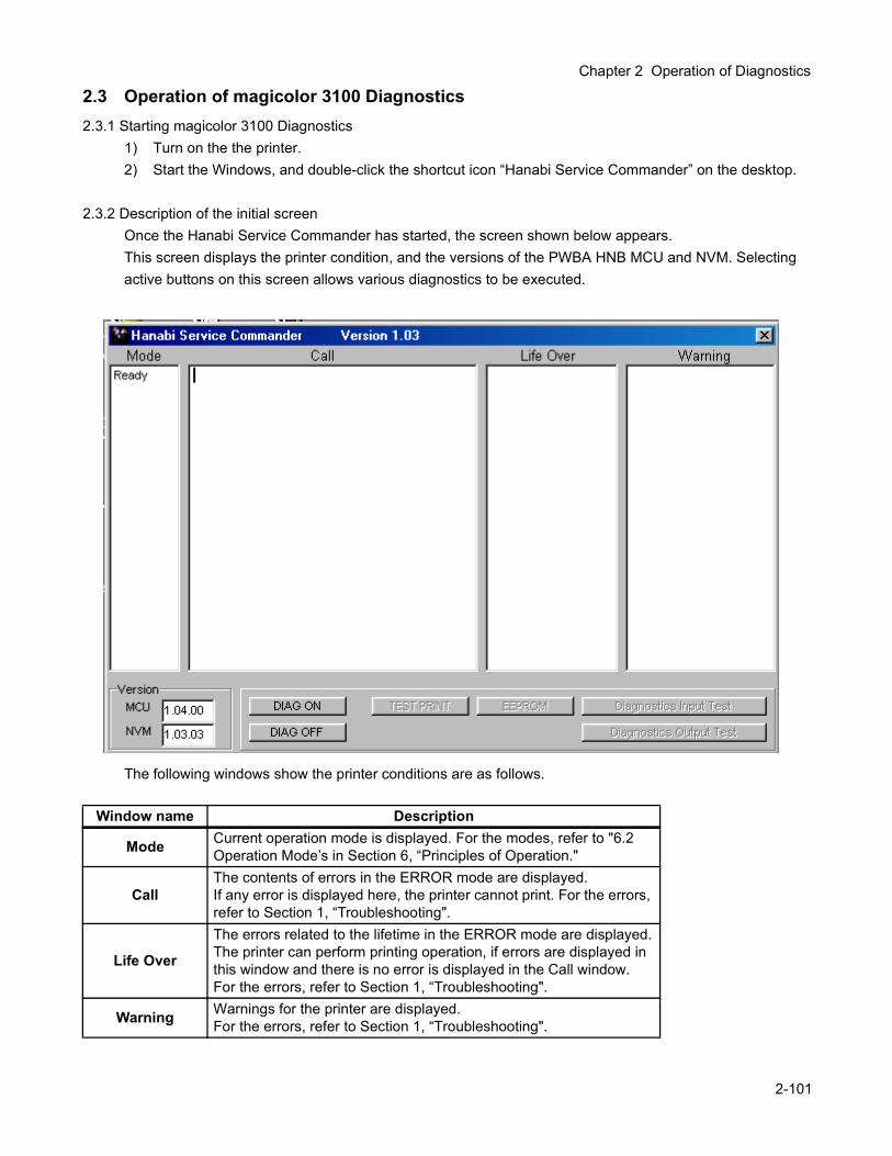
Chapter 2 Operation of Diagnostics
2.3 Operation of magicolor 3100 Diagnostics2.3.1 Starting magicolor 3100 Diagnostics
1) Turn on the the printer.2) Start the Windows, and double-click the shortcut icon “Hanabi Service Commander” on the desktop.
2.3.2 Description of the initial screenOnce the Hanabi Service Commander has started, the screen shown below appears.This screen displays the printer condition, and the versions of the PWBA HNB MCU and NVM. Selecting active buttons on this screen allows various diagnostics to be executed.
The following windows show the printer conditions are as follows.
Window name Description
Mode Current operation mode is displayed. For the modes, refer to "6.2 Operation Mode’s in Section 6, “Principles of Operation."
CallThe contents of errors in the ERROR mode are displayed.If any error is displayed here, the printer cannot print. For the errors, refer to Section 1, “Troubleshooting".
Life Over
The errors related to the lifetime in the ERROR mode are displayed.The printer can perform printing operation, if errors are displayed in this window and there is no error is displayed in the Call window.For the errors, refer to Section 1, “Troubleshooting".
Warning Warnings for the printer are displayed.For the errors, refer to Section 1, “Troubleshooting".
2-101
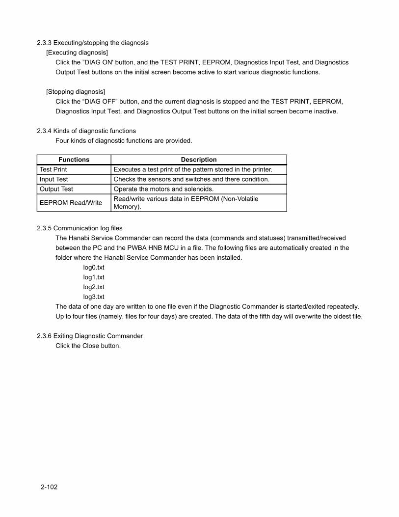
2.3.3 Executing/stopping the diagnosis[Executing diagnosis]
Click the ”DIAG ON' button, and the TEST PRINT, EEPROM, Diagnostics Input Test, and Diagnostics Output Test buttons on the initial screen become active to start various diagnostic functions.
[Stopping diagnosis]Click the “DIAG OFF” button, and the current diagnosis is stopped and the TEST PRINT, EEPROM, Diagnostics Input Test, and Diagnostics Output Test buttons on the initial screen become inactive.
2.3.4 Kinds of diagnostic functionsFour kinds of diagnostic functions are provided.
2.3.5 Communication log filesThe Hanabi Service Commander can record the data (commands and statuses) transmitted/received between the PC and the PWBA HNB MCU in a file. The following files are automatically created in the folder where the Hanabi Service Commander has been installed.
log0.txtlog1.txtlog2.txtlog3.txt
The data of one day are written to one file even if the Diagnostic Commander is started/exited repeatedly. Up to four files (namely, files for four days) are created. The data of the fifth day will overwrite the oldest file.
2.3.6 Exiting Diagnostic CommanderClick the Close button.
Functions DescriptionTest Print Executes a test print of the pattern stored in the printer.Input Test Checks the sensors and switches and there condition.Output Test Operate the motors and solenoids.
EEPROM Read/Write Read/write various data in EEPROM (Non-Volatile Memory).
2-102
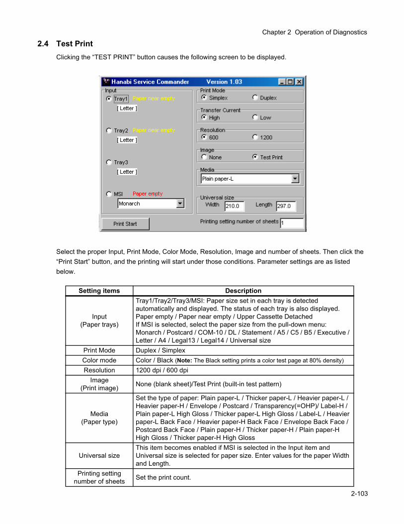
Chapter 2 Operation of Diagnostics
2.4 Test PrintClicking the “TEST PRINT” button causes the following screen to be displayed.
Select the proper Input, Print Mode, Color Mode, Resolution, Image and number of sheets. Then click the “Print Start” button, and the printing will start under those conditions. Parameter settings are as listed below.
Setting items Description
Input(Paper trays)
Tray1/Tray2/Tray3/MSI: Paper size set in each tray is detected automatically and displayed. The status of each tray is also displayed.Paper empty / Paper near empty / Upper Cassette DetachedIf MSI is selected, select the paper size from the pull-down menu: Monarch / Postcard / COM-10 / DL / Statement / A5 / C5 / B5 / Executive / Letter / A4 / Legal13 / Legal14 / Universal size
Print Mode Duplex / SimplexColor mode Color / Black (Note: The Black setting prints a color test page at 80% density)Resolution 1200 dpi / 600 dpi
Image(Print image) None (blank sheet)/Test Print (built-in test pattern)
Media(Paper type)
Set the type of paper: Plain paper-L / Thicker paper-L / Heavier paper-L / Heavier paper-H / Envelope / Postcard / Transparency(=OHP)/ Label-H / Plain paper-L High Gloss / Thicker paper-L High Gloss / Label-L / Heavier paper-L Back Face / Heavier paper-H Back Face / Envelope Back Face / Postcard Back Face / Plain paper-H / Thicker paper-H / Plain paper-H High Gloss / Thicker paper-H High Gloss
Universal sizeThis item becomes enabled if MSI is selected in the Input item and Universal size is selected for paper size. Enter values for the paper Width and Length.
Printing setting number of sheets Set the print count.
2-103
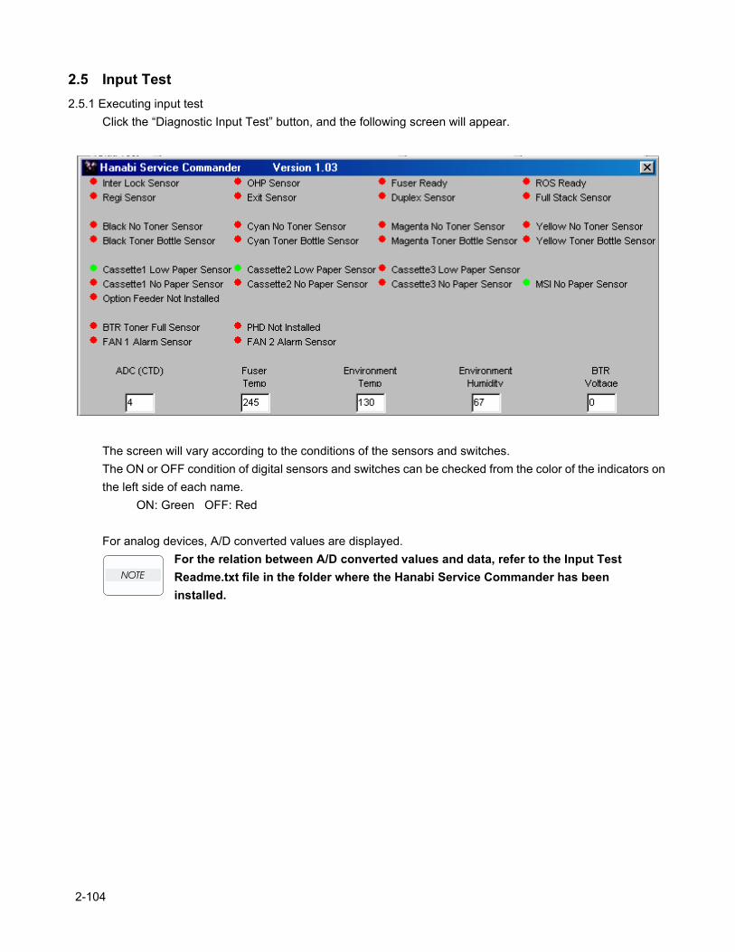
2.5 Input Test2.5.1 Executing input test
Click the “Diagnostic Input Test” button, and the following screen will appear.
The screen will vary according to the conditions of the sensors and switches.The ON or OFF condition of digital sensors and switches can be checked from the color of the indicators on the left side of each name.
ON: Green OFF: Red
For analog devices, A/D converted values are displayed.For the relation between A/D converted values and data, refer to the Input Test Readme.txt file in the folder where the Hanabi Service Commander has been installed.
2-104
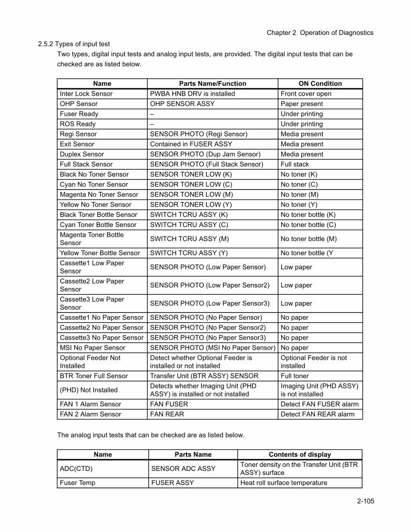
Chapter 2 Operation of Diagnostics
2.5.2 Types of input testTwo types, digital input tests and analog input tests, are provided. The digital input tests that can be checked are as listed below.
The analog input tests that can be checked are as listed below.
Name Parts Name/Function ON ConditionInter Lock Sensor PWBA HNB DRV is installed Front cover openOHP Sensor OHP SENSOR ASSY Paper presentFuser Ready – Under printingROS Ready – Under printingRegi Sensor SENSOR PHOTO (Regi Sensor) Media presentExit Sensor Contained in FUSER ASSY Media presentDuplex Sensor SENSOR PHOTO (Dup Jam Sensor) Media presentFull Stack Sensor SENSOR PHOTO (Full Stack Sensor) Full stackBlack No Toner Sensor SENSOR TONER LOW (K) No toner (K)Cyan No Toner Sensor SENSOR TONER LOW (C) No toner (C)Magenta No Toner Sensor SENSOR TONER LOW (M) No toner (M)Yellow No Toner Sensor SENSOR TONER LOW (Y) No toner (Y)Black Toner Bottle Sensor SWITCH TCRU ASSY (K) No toner bottle (K)Cyan Toner Bottle Sensor SWITCH TCRU ASSY (C) No toner bottle (C)Magenta Toner Bottle Sensor SWITCH TCRU ASSY (M) No toner bottle (M)
Yellow Toner Bottle Sensor SWITCH TCRU ASSY (Y) No toner bottle (YCassette1 Low Paper Sensor SENSOR PHOTO (Low Paper Sensor) Low paper
Cassette2 Low Paper Sensor SENSOR PHOTO (Low Paper Sensor2) Low paper
Cassette3 Low Paper Sensor SENSOR PHOTO (Low Paper Sensor3) Low paper
Cassette1 No Paper Sensor SENSOR PHOTO (No Paper Sensor) No paperCassette2 No Paper Sensor SENSOR PHOTO (No Paper Sensor2) No paperCassette3 No Paper Sensor SENSOR PHOTO (No Paper Sensor3) No paperMSI No Paper Sensor SENSOR PHOTO (MSI No Paper Sensor) No paperOptional Feeder Not Installed
Detect whether Optional Feeder is installed or not installed
Optional Feeder is not installed
BTR Toner Full Sensor Transfer Unit (BTR ASSY) SENSOR Full toner
(PHD) Not Installed Detects whether Imaging Unit (PHD ASSY) is installed or not installed
Imaging Unit (PHD ASSY) is not installed
FAN 1 Alarm Sensor FAN FUSER Detect FAN FUSER alarmFAN 2 Alarm Sensor FAN REAR Detect FAN REAR alarm
Name Parts Name Contents of display
ADC(CTD) SENSOR ADC ASSY Toner density on the Transfer Unit (BTR ASSY) surface
Fuser Temp FUSER ASSY Heat roll surface temperature
2-105

Environment Temp SENSOR HUM TEMP Inside temperature of printerEnvironment Humidity SENSOR HUM TEMP Inside humidity of printer
BTR Voltage Transfer Unit (BTR ASSY) Voltage being applied to the Transfer Unit (BTR ASSY)
Name Parts Name Contents of display
2-106
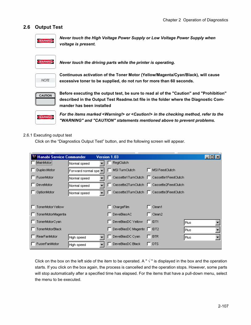
Chapter 2 Operation of Diagnostics
2.6 Output Test
Never touch the High Voltage Power Supply or Low Voltage Power Supply when voltage is present.
Never touch the driving parts while the printer is operating.
Continuous activation of the Toner Motor (Yellow/Magenta/Cyan/Black), will cause excessive toner to be supplied, do not run for more than 60 seconds.
Before executing the output test, be sure to read al of the "Caution" and "Prohibition" described in the Output Test Readme.txt file in the folder where the Diagnostic Com-mander has been installed
For the items marked <Warning!> or <Caution!> in the checking method, refer to the "WARNING" and "CAUTION" statements mentioned above to prevent problems.
2.6.1 Executing output testClick on the “Diagnostics Output Test” button, and the following screen will appear.
Click on the box on the left side of the item to be operated. A " √ " is displayed in the box and the operation starts. If you click on the box again, the process is cancelled and the operation stops. However, some parts will stop automatically after a specified time has elapsed. For the items that have a pull-down menu, select the menu to be executed.
2-107
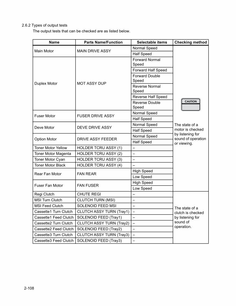
2.6.2 Types of output testsThe output tests that can be checked are as listed below.
Name Parts Name/Function Selectable items Checking method
Main Motor MAIN DRIVE ASSYNormal Speed
The state of a motor is checked by listening for sound of operation or viewing.
Half Speed
Duplex Motor MOT ASSY DUP
Forward Normal SpeedForward Half SpeedForward Double SpeedReverse Normal SpeedReverse Half SpeedReverse Double Speed
Fuser Motor FUSER DRIVE ASSYNormal SpeedHalf Speed
Deve Motor DEVE DRIVE ASSYNormal SpeedHalf Speed
Option Motor DRIVE ASSY FEEDERNormal SpeedHalf Speed
Toner Motor Yellow HOLDER TCRU ASSY (1) –Toner Motor Magenta HOLDER TCRU ASSY (2) –Toner Motor Cyan HOLDER TCRU ASSY (3) –Toner Motor Black HOLDER TCRU ASSY (4) –
Rear Fan Motor FAN REARHigh SpeedLow Speed
Fuser Fan Motor FAN FUSERHigh SpeedLow Speed
Regi Clutch CHUTE REGI –
The state of a clutch is checked by listening for sound of operation.
MSI Turn Clutch CLUTCH TURN (MSI) –MSI Feed Clutch SOLENOID FEED MSI –Cassette1 Turn Clutch CLUTCH ASSY TURN (Tray1) –Cassette1 Feed Clutch SOLENOID FEED (Tray1) –Cassette2 Turn Clutch CLUTCH ASSY TURN (Tray2) –Cassette2 Feed Clutch SOLENOID FEED (Tray2) –Cassette3 Turn Clutch CLUTCH ASSY TURN (Tray3) –Cassette3 Feed Clutch SOLENOID FEED (Tray3) –
2-108
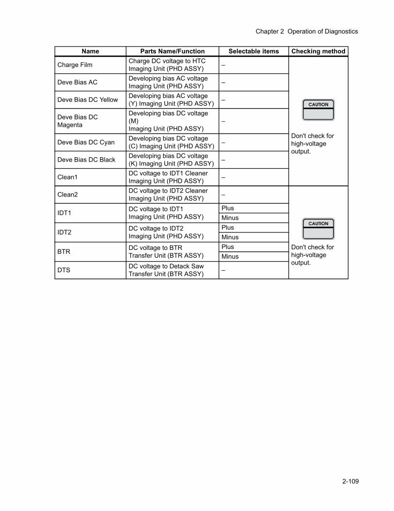
Chapter 2 Operation of Diagnostics
Name Parts Name/Function Selectable items Checking method
Charge Film Charge DC voltage to HTC Imaging Unit (PHD ASSY) –
Don't check for high-voltage output.
Deve Bias AC Developing bias AC voltage Imaging Unit (PHD ASSY) –
Deve Bias DC Yellow Developing bias AC voltage (Y) Imaging Unit (PHD ASSY) –
Deve Bias DC Magenta
Developing bias DC voltage (M)Imaging Unit (PHD ASSY)
–
Deve Bias DC Cyan Developing bias DC voltage (C) Imaging Unit (PHD ASSY) –
Deve Bias DC Black Developing bias DC voltage (K) Imaging Unit (PHD ASSY) –
Clean1 DC voltage to IDT1 Cleaner Imaging Unit (PHD ASSY) –
Clean2 DC voltage to IDT2 Cleaner Imaging Unit (PHD ASSY) –
Don't check for high-voltage output.
IDT1 DC voltage to IDT1Imaging Unit (PHD ASSY)
PlusMinus
IDT2 DC voltage to IDT2Imaging Unit (PHD ASSY)
PlusMinus
BTR DC voltage to BTRTransfer Unit (BTR ASSY)
PlusMinus
DTS DC voltage to Detack SawTransfer Unit (BTR ASSY) –
2-109
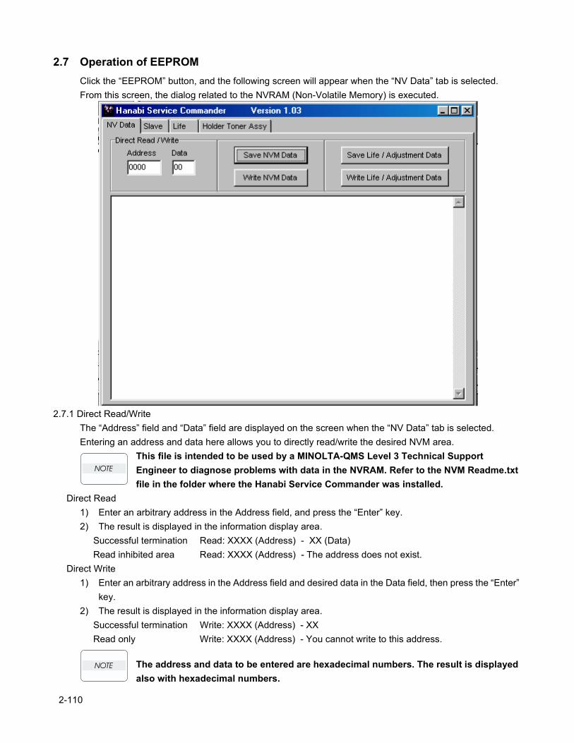
2.7 Operation of EEPROMClick the “EEPROM” button, and the following screen will appear when the “NV Data” tab is selected.From this screen, the dialog related to the NVRAM (Non-Volatile Memory) is executed.
2.7.1 Direct Read/WriteThe “Address” field and “Data” field are displayed on the screen when the “NV Data” tab is selected. Entering an address and data here allows you to directly read/write the desired NVM area.
This file is intended to be used by a MINOLTA-QMS Level 3 Technical Support Engineer to diagnose problems with data in the NVRAM. Refer to the NVM Readme.txt file in the folder where the Hanabi Service Commander was installed.
Direct Read1) Enter an arbitrary address in the Address field, and press the “Enter” key.2) The result is displayed in the information display area.
Successful termination Read: XXXX (Address) - XX (Data)Read inhibited area Read: XXXX (Address) - The address does not exist.
Direct Write1) Enter an arbitrary address in the Address field and desired data in the Data field, then press the “Enter”
key.2) The result is displayed in the information display area.
Successful termination Write: XXXX (Address) - XXRead only Write: XXXX (Address) - You cannot write to this address.
The address and data to be entered are hexadecimal numbers. The result is displayed also with hexadecimal numbers.
2-110
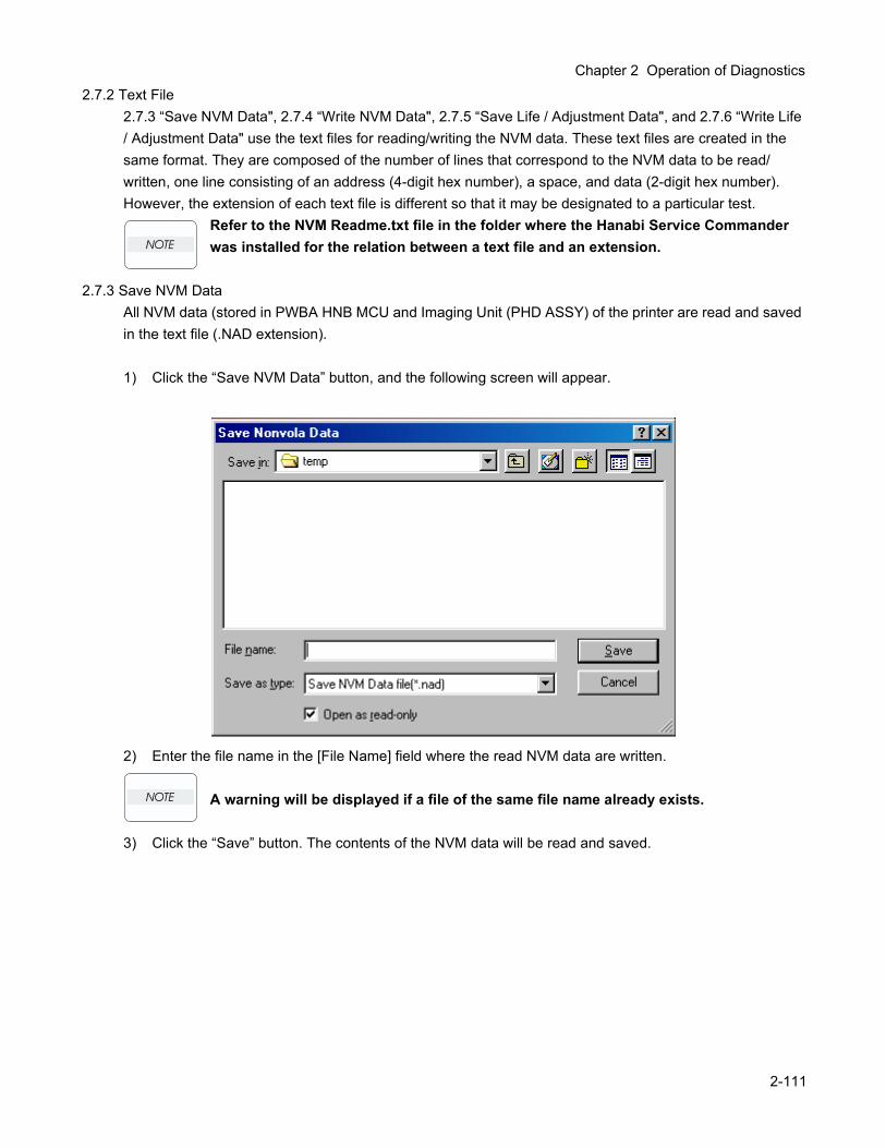
Chapter 2 Operation of Diagnostics
2.7.2 Text File2.7.3 “Save NVM Data", 2.7.4 “Write NVM Data", 2.7.5 “Save Life / Adjustment Data", and 2.7.6 “Write Life / Adjustment Data" use the text files for reading/writing the NVM data. These text files are created in the same format. They are composed of the number of lines that correspond to the NVM data to be read/written, one line consisting of an address (4-digit hex number), a space, and data (2-digit hex number). However, the extension of each text file is different so that it may be designated to a particular test.
Refer to the NVM Readme.txt file in the folder where the Hanabi Service Commander was installed for the relation between a text file and an extension.
2.7.3 Save NVM DataAll NVM data (stored in PWBA HNB MCU and Imaging Unit (PHD ASSY) of the printer are read and saved in the text file (.NAD extension).
1) Click the “Save NVM Data” button, and the following screen will appear.
2) Enter the file name in the [File Name] field where the read NVM data are written.
A warning will be displayed if a file of the same file name already exists.
3) Click the “Save” button. The contents of the NVM data will be read and saved.
2-111
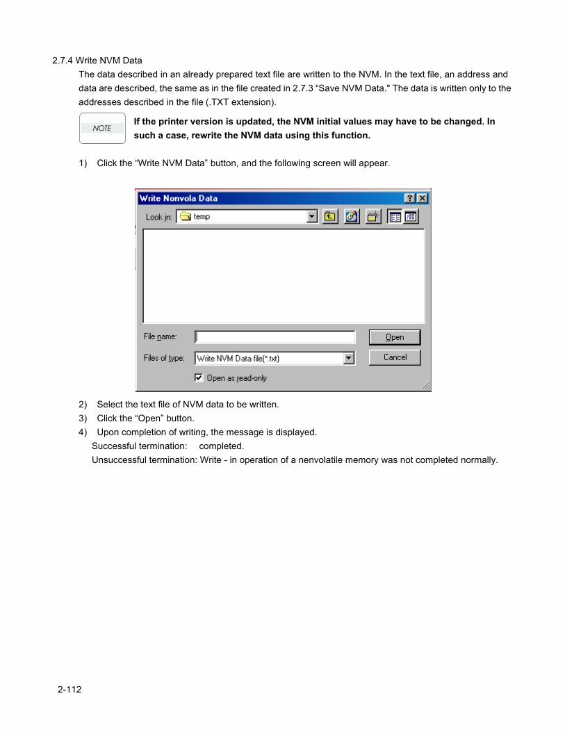
2.7.4 Write NVM DataThe data described in an already prepared text file are written to the NVM. In the text file, an address and data are described, the same as in the file created in 2.7.3 “Save NVM Data." The data is written only to the addresses described in the file (.TXT extension).
If the printer version is updated, the NVM initial values may have to be changed. In such a case, rewrite the NVM data using this function.
1) Click the “Write NVM Data” button, and the following screen will appear.
2) Select the text file of NVM data to be written.3) Click the “Open” button.4) Upon completion of writing, the message is displayed.
Successful termination: completed.Unsuccessful termination: Write - in operation of a nenvolatile memory was not completed normally.
2-112
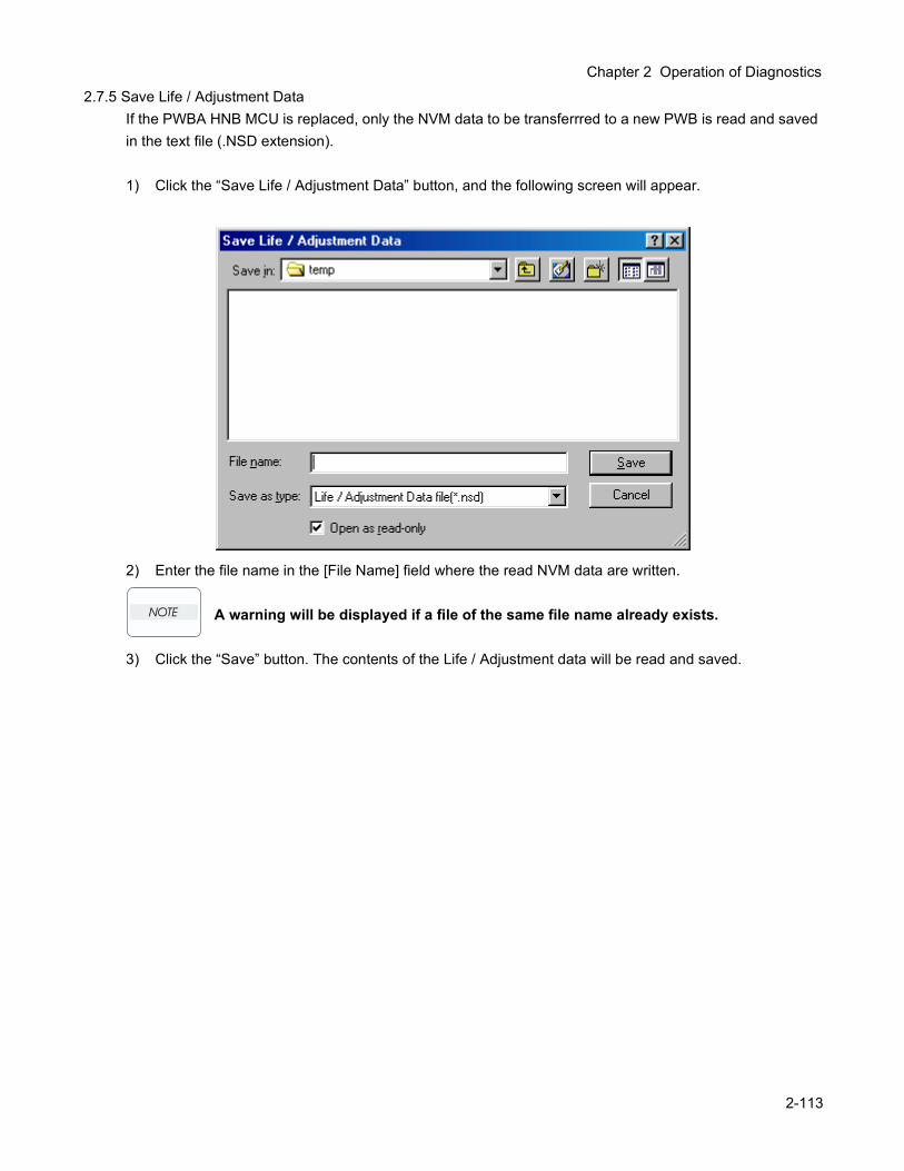
Chapter 2 Operation of Diagnostics
2.7.5 Save Life / Adjustment DataIf the PWBA HNB MCU is replaced, only the NVM data to be transferrred to a new PWB is read and saved in the text file (.NSD extension).
1) Click the “Save Life / Adjustment Data” button, and the following screen will appear.
2) Enter the file name in the [File Name] field where the read NVM data are written.
A warning will be displayed if a file of the same file name already exists.
3) Click the “Save” button. The contents of the Life / Adjustment data will be read and saved.
2-113
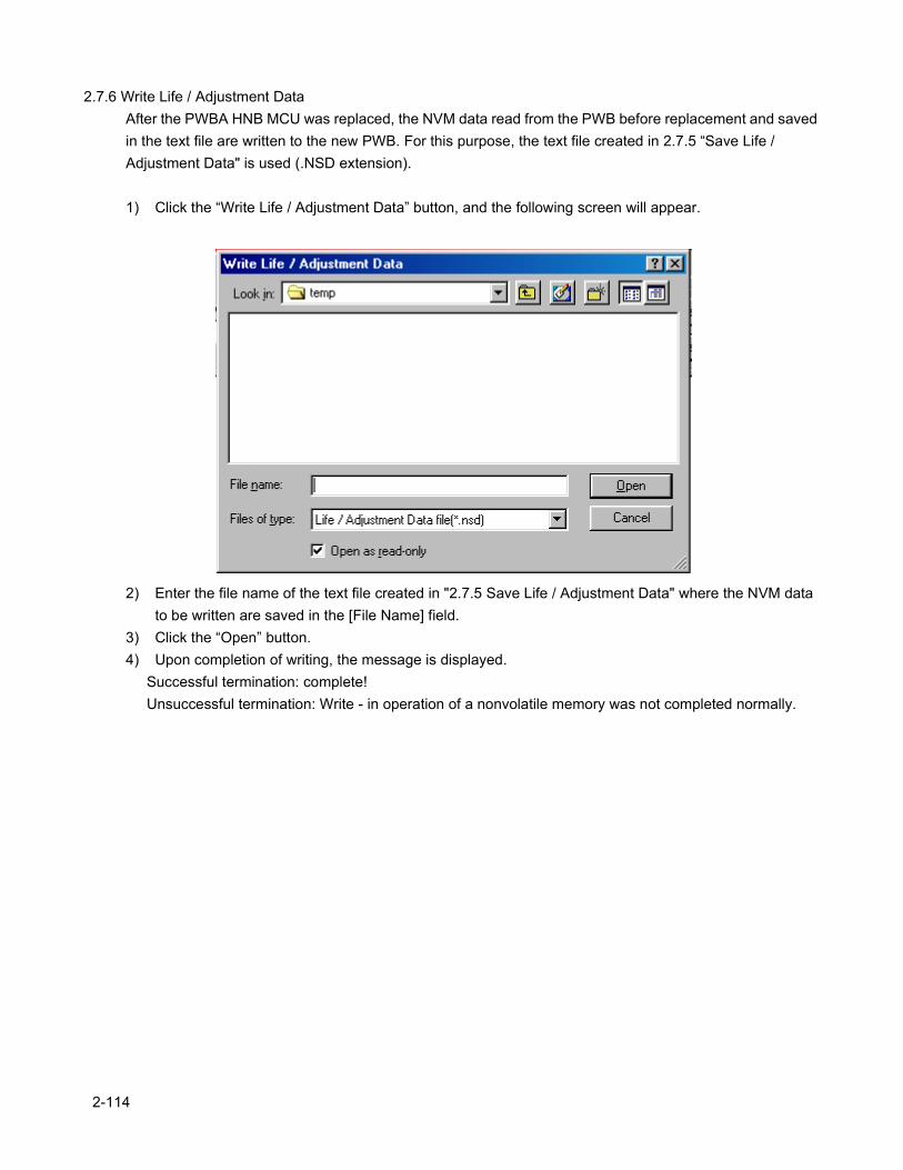
2.7.6 Write Life / Adjustment DataAfter the PWBA HNB MCU was replaced, the NVM data read from the PWB before replacement and saved in the text file are written to the new PWB. For this purpose, the text file created in 2.7.5 “Save Life / Adjustment Data" is used (.NSD extension).
1) Click the “Write Life / Adjustment Data” button, and the following screen will appear.
2) Enter the file name of the text file created in "2.7.5 Save Life / Adjustment Data" where the NVM data to be written are saved in the [File Name] field.
3) Click the “Open” button.4) Upon completion of writing, the message is displayed.
Successful termination: complete!Unsuccessful termination: Write - in operation of a nonvolatile memory was not completed normally.
2-114
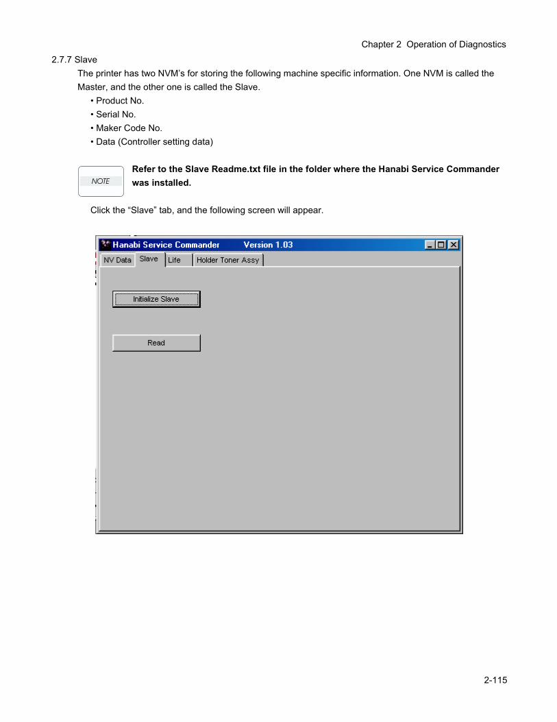
Chapter 2 Operation of Diagnostics
2.7.7 SlaveThe printer has two NVM’s for storing the following machine specific information. One NVM is called the Master, and the other one is called the Slave.
• Product No.• Serial No.• Maker Code No.• Data (Controller setting data)
Refer to the Slave Readme.txt file in the folder where the Hanabi Service Commander was installed.
Click the “Slave” tab, and the following screen will appear.
2-115
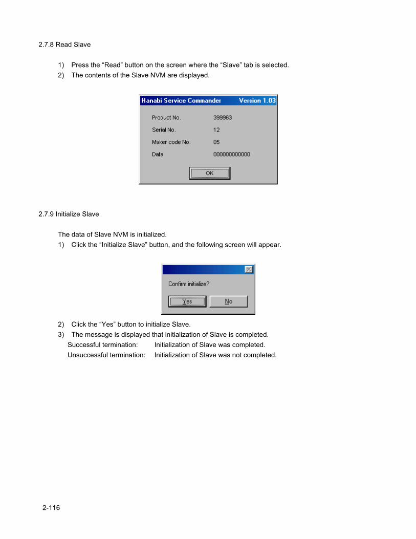
2.7.8 Read Slave
1) Press the “Read” button on the screen where the “Slave” tab is selected.2) The contents of the Slave NVM are displayed.
2.7.9 Initialize Slave
The data of Slave NVM is initialized.1) Click the “Initialize Slave” button, and the following screen will appear.
2) Click the “Yes” button to initialize Slave.3) The message is displayed that initialization of Slave is completed.
Successful termination: Initialization of Slave was completed.Unsuccessful termination: Initialization of Slave was not completed.
2-116
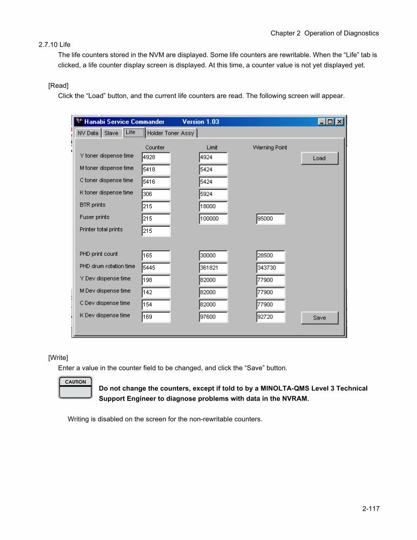
Chapter 2 Operation of Diagnostics
2.7.10 LifeThe life counters stored in the NVM are displayed. Some life counters are rewritable. When the “Life” tab is clicked, a life counter display screen is displayed. At this time, a counter value is not yet displayed yet.
[Read]Click the “Load” button, and the current life counters are read. The following screen will appear.
[Write]Enter a value in the counter field to be changed, and click the “Save” button.
Do not change the counters, except if told to by a MINOLTA-QMS Level 3 Technical Support Engineer to diagnose problems with data in the NVRAM.
Writing is disabled on the screen for the non-rewritable counters.
2-117
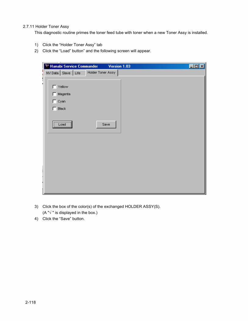
2.7.11 Holder Toner AssyThis diagnostic routine primes the toner feed tube with toner when a new Toner Assy is installed.
1) Click the “Holder Toner Assy” tab2) Click the “Load” button” and the following screen will appear.
3) Click the box of the color(s) of the exchanged HOLDER ASSY(S).(A "√ " is displayed in the box.)
4) Click the “Save” button.
2-118
Chapter 3 Removal and Replacement Procedures

Chapter 3 Removal and Replacement Procedures
1. Removal and Replacement ProceduresParts removal and replacement procedures are described in major 12 items which correspond to classification of parts list.
RRP 1 COVERS RRP 2 PAPER CASSETTE RRP 3 PAPER FEEDER RRP 4 HOUSING ASSY RETARD RRP 5 FRONT ASSY IN RRP 6 CHUTE ASSY OUT RRP 7 CHUTE ASSY EXIT RRP 8 BTR ASSY & FUSER RRP 9 XEROGRAPHICS RRP 10 TCRU ASSY RRP 11 FRAME & DRIVE RRP 12 ELECTRICAL
Parts are controlled as spare parts. When servicing for parts for which no procedures are described, observe their assembling condition before starting the service.
For optional parts, refer to the manual for them.
Though the optional parts are assumed to be removed, they may not be removed if not required for the purpose of service operation.
1.1 Before starting service work Turn the power OFF and remove the power cord from the electric outlet. Remove the PHD ASSY (PL9.1.3) before starting the disassembling process. Remove the TCRU ASSY as necessary, and perform disassembly process. When performing service operation for parts around the FUSER ASSY, start the service after the
FUSER ASSY and parts around it have cooled down. Do not give forcible power to prevent damage of parts or functions. Since a wide variety of screws are used, be careful not to mistake their positions, to prevent crushing of
the screw holes or other troubles. Wear a wrist band or the like as far as possible to remove static electricity of the human body.
3-119
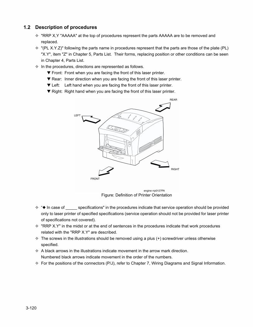
1.2 Description of procedures "RRP X,Y "AAAAA" at the top of procedures represent the parts AAAAA are to be removed and
replaced. "(PL X.Y.Z)" following the parts name in procedures represent that the parts are those of the plate (PL)
"X.Y", item "Z" in Chapter 5, Parts List. Their forms, replacing position or other conditions can be seen in Chapter 4, Parts List.
In the procedures, directions are represented as follows. Front: Front when you are facing the front of this laser printer. Rear: Inner direction when you are facing the front of this laser printer. Left: Left hand when you are facing the front of this laser printer. Right: Right hand when you are facing the front of this laser printer.
Figure: Definition of Printer Orientation
“ In case of _____ specifications" in the procedures indicate that service operation should be provided only to laser printer of specified specifications (service operation should not be provided for laser printer of specifications not covered).
"RRP X.Y" in the midst or at the end of sentences in the procedures indicate that work procedures related with the "RRP X.Y" are described.
The screws in the illustrations should be removed using a plus (+) screwdriver unless otherwise specified.
A black arrows in the illustrations indicate movement in the arrow mark direction.Numbered black arrows indicate movement in the order of the numbers.
For the positions of the connectors (P/J), refer to Chapter 7, Wiring Diagrams and Signal Information.
3-120
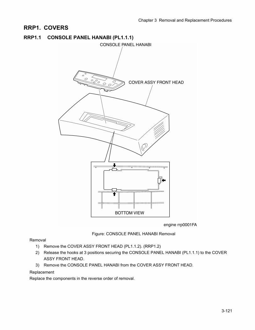
Chapter 3 Removal and Replacement Procedures
RRP1. COVERSRRP1.1 CONSOLE PANEL HANABI (PL1.1.1)
Figure: CONSOLE PANEL HANABI RemovalRemoval
1) Remove the COVER ASSY FRONT HEAD (PL1.1.2). (RRP1.2)2) Release the hooks at 3 positions securing the CONSOLE PANEL HANABI (PL1.1.1) to the COVER
ASSY FRONT HEAD.3) Remove the CONSOLE PANEL HANABI from the COVER ASSY FRONT HEAD.
ReplacementReplace the components in the reverse order of removal.
3-121
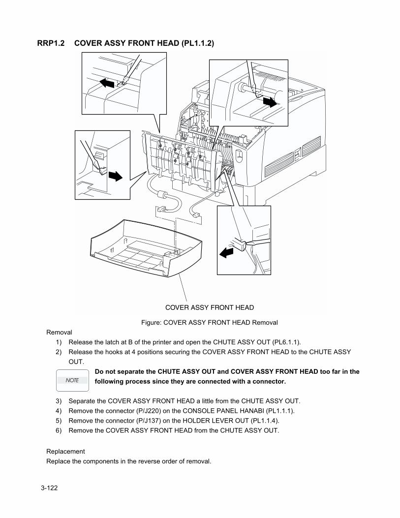
RRP1.2 COVER ASSY FRONT HEAD (PL1.1.2)
Figure: COVER ASSY FRONT HEAD RemovalRemoval
1) Release the latch at B of the printer and open the CHUTE ASSY OUT (PL6.1.1).2) Release the hooks at 4 positions securing the COVER ASSY FRONT HEAD to the CHUTE ASSY
OUT.Do not separate the CHUTE ASSY OUT and COVER ASSY FRONT HEAD too far in the following process since they are connected with a connector.
3) Separate the COVER ASSY FRONT HEAD a little from the CHUTE ASSY OUT.4) Remove the connector (P/J220) on the CONSOLE PANEL HANABI (PL1.1.1).5) Remove the connector (P/J137) on the HOLDER LEVER OUT (PL1.1.4).6) Remove the COVER ASSY FRONT HEAD from the CHUTE ASSY OUT.
ReplacementReplace the components in the reverse order of removal.
3-122

Chapter 3 Removal and Replacement Procedures
3-123
Blank page.
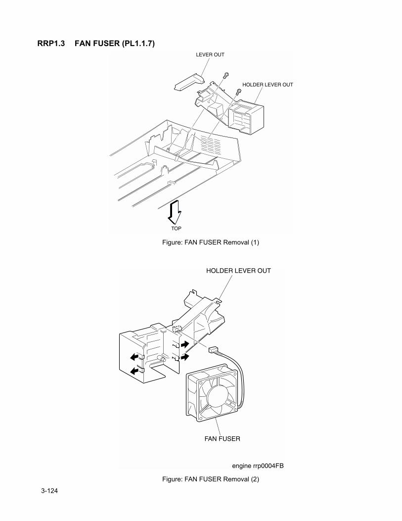
RRP1.3 FAN FUSER (PL1.1.7)
Figure: FAN FUSER Removal (1)
Figure: FAN FUSER Removal (2)
3-124
Chapter 3 Removal and Replacement Procedures
Removal1) Remove the COVER ASSY FRONT HEAD. (RRP1.2)2) Remove 2 screws securing the HOLDER LEVER OUT (PL1.1.4) from the rear of the COVER ASSY
FRONT HEAD.3) Remove the HOLDER LEVER OUT (PL1.1.4) from the COVER ASSY FRONT HEAD together with the
FAN FUSER, LEVER OUT (PL1.1.5).4) Remove the LEVER OUT from the HOLDER LEVER OUT.5) Remove the connector (P/J137) of the FAN FUSER.
Take note and remember how the wire harness is routed because the new wiring harness must be routed in the same way.
6) Release the hooks securing the FAN FUSER at 4 positions to the HOLDER LEVER OUT.7) Remove the FAN FUSER from the HOLDER LEVER OUT.
ReplacementReplace the components in the reverse order of removal.
When mounting the FAN FUSER on the HOLDER LEVER OUT, route the wire harness in the same way that the removed fan’s harness was routed.
3-125
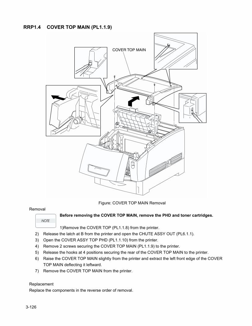
RRP1.4 COVER TOP MAIN (PL1.1.9)
Figure: COVER TOP MAIN RemovalRemoval
Before removing the COVER TOP MAIN, remove the PHD and toner cartridges.
1)Remove the COVER TOP (PL1.1.8) from the printer.2) Release the latch at B from the printer and open the CHUTE ASSY OUT (PL6.1.1).3) Open the COVER ASSY TOP PHD (PL1.1.10) from the printer.4) Remove 2 screws securing the COVER TOP MAIN (PL1.1.9) to the printer.5) Release the hooks at 4 positions securing the rear of the COVER TOP MAIN to the printer.6) Raise the COVER TOP MAIN slightly from the printer and extract the left front edge of the COVER
TOP MAIN deflecting it leftward.7) Remove the COVER TOP MAIN from the printer.
ReplacementReplace the components in the reverse order of removal.
3-126
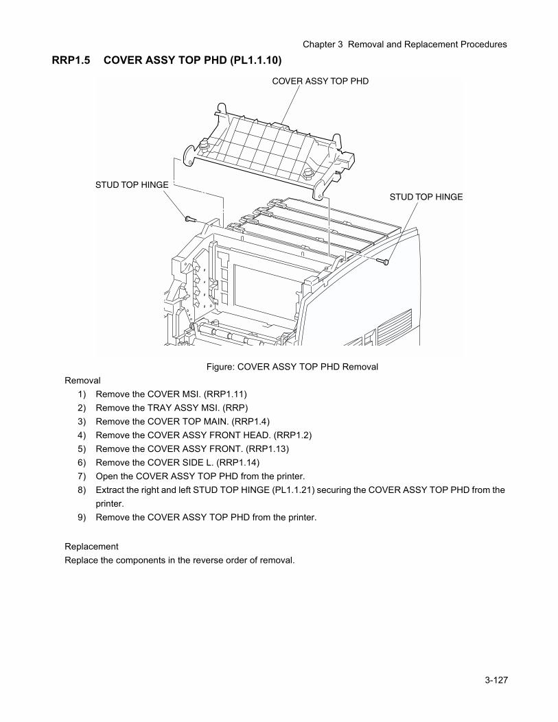
Chapter 3 Removal and Replacement Procedures
RRP1.5 COVER ASSY TOP PHD (PL1.1.10)
Figure: COVER ASSY TOP PHD RemovalRemoval
1) Remove the COVER MSI. (RRP1.11)2) Remove the TRAY ASSY MSI. (RRP)3) Remove the COVER TOP MAIN. (RRP1.4)4) Remove the COVER ASSY FRONT HEAD. (RRP1.2)5) Remove the COVER ASSY FRONT. (RRP1.13)6) Remove the COVER SIDE L. (RRP1.14)7) Open the COVER ASSY TOP PHD from the printer.8) Extract the right and left STUD TOP HINGE (PL1.1.21) securing the COVER ASSY TOP PHD from the
printer.9) Remove the COVER ASSY TOP PHD from the printer.
ReplacementReplace the components in the reverse order of removal.
3-127
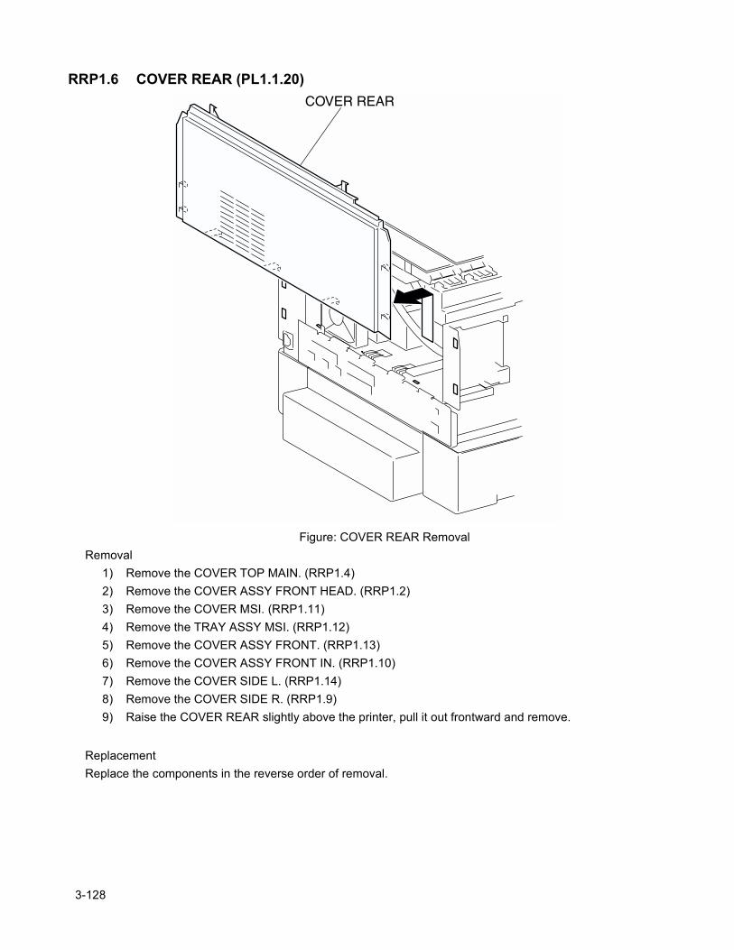
RRP1.6 COVER REAR (PL1.1.20)
Figure: COVER REAR RemovalRemoval
1) Remove the COVER TOP MAIN. (RRP1.4)2) Remove the COVER ASSY FRONT HEAD. (RRP1.2)3) Remove the COVER MSI. (RRP1.11)4) Remove the TRAY ASSY MSI. (RRP1.12)5) Remove the COVER ASSY FRONT. (RRP1.13)6) Remove the COVER ASSY FRONT IN. (RRP1.10)7) Remove the COVER SIDE L. (RRP1.14)8) Remove the COVER SIDE R. (RRP1.9)9) Raise the COVER REAR slightly above the printer, pull it out frontward and remove.
ReplacementReplace the components in the reverse order of removal.
3-128
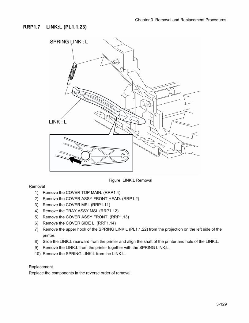
Chapter 3 Removal and Replacement Procedures
RRP1.7 LINK:L (PL1.1.23)
Figure: LINK:L RemovalRemoval
1) Remove the COVER TOP MAIN. (RRP1.4)2) Remove the COVER ASSY FRONT HEAD. (RRP1.2)3) Remove the COVER MSI. (RRP1.11)4) Remove the TRAY ASSY MSI. (RRP1.12)5) Remove the COVER ASSY FRONT. (RRP1.13)6) Remove the COVER SIDE L. (RRP1.14)7) Remove the upper hook of the SPRING LINK:L (PL1.1.22) from the projection on the left side of the
printer.8) Slide the LINK:L rearward from the printer and align the shaft of the printer and hole of the LINK:L.9) Remove the LINK:L from the printer together with the SPRING LINK:L.10) Remove the SPRING LINK:L from the LINK:L.
ReplacementReplace the components in the reverse order of removal.
3-129
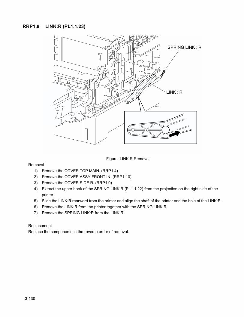
RRP1.8 LINK:R (PL1.1.23)
Figure: LINK:R RemovalRemoval
1) Remove the COVER TOP MAIN. (RRP1.4)2) Remove the COVER ASSY FRONT IN. (RRP1.10)3) Remove the COVER SIDE R. (RRP1.9)4) Extract the upper hook of the SPRING LINK:R (PL1.1.22) from the projection on the right side of the
printer.5) Slide the LINK:R rearward from the printer and align the shaft of the printer and the hole of the LINK:R.6) Remove the LINK:R from the printer together with the SPRING LINK:R.7) Remove the SPRING LINK:R from the LINK:R.
ReplacementReplace the components in the reverse order of removal.
3-130
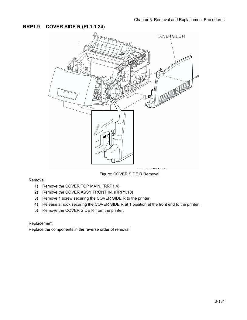
Chapter 3 Removal and Replacement Procedures
RRP1.9 COVER SIDE R (PL1.1.24)
Figure: COVER SIDE R RemovalRemoval
1) Remove the COVER TOP MAIN. (RRP1.4)2) Remove the COVER ASSY FRONT IN. (RRP1.10)3) Remove 1 screw securing the COVER SIDE R to the printer.4) Release a hook securing the COVER SIDE R at 1 position at the front end to the printer.5) Remove the COVER SIDE R from the printer.
ReplacementReplace the components in the reverse order of removal.
3-131
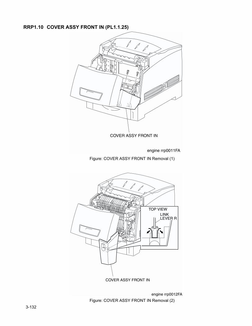
RRP1.10 COVER ASSY FRONT IN (PL1.1.25)
Figure: COVER ASSY FRONT IN Removal (1)
Figure: COVER ASSY FRONT IN Removal (2)
3-132
Chapter 3 Removal and Replacement Procedures
Removal1) Release the latch at B from the printer and open the FRONT ASSY IN (PL5.1.1) together with the CHUTE ASSY OUT (PL6.1.1).
2) Remove 2 screws securing the COVER ASSY FRONT IN to the FRONT ASSY IN.3) Release the latch at A from the printer and open the CHUTE ASSY OUT.
In the following process, do not separate the COVER ASSY FRONT IN and LINK:R too far since they are connected.
4) Pull out the COVER ASSY FRONT IN slightly from the FRONT ASSY IN.5) Release the LINK LEVER: R shaft from the leaf spring at the back of the COVER ASSY FRONT IN
and remove the COVER ASSY FRONT IN.
ReplacementReplace the components in the reverse order of removal.
3-133
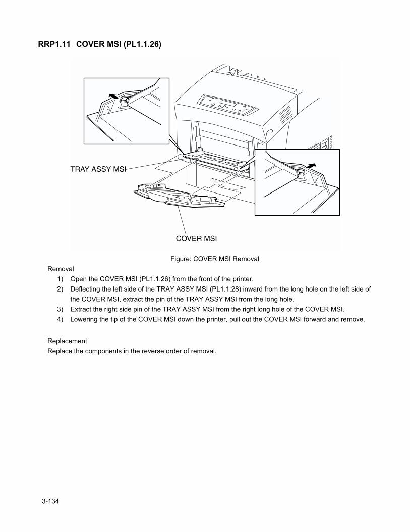
RRP1.11 COVER MSI (PL1.1.26)
Figure: COVER MSI RemovalRemoval
1) Open the COVER MSI (PL1.1.26) from the front of the printer.2) Deflecting the left side of the TRAY ASSY MSI (PL1.1.28) inward from the long hole on the left side of
the COVER MSI, extract the pin of the TRAY ASSY MSI from the long hole.3) Extract the right side pin of the TRAY ASSY MSI from the right long hole of the COVER MSI.4) Lowering the tip of the COVER MSI down the printer, pull out the COVER MSI forward and remove.
ReplacementReplace the components in the reverse order of removal.
3-134
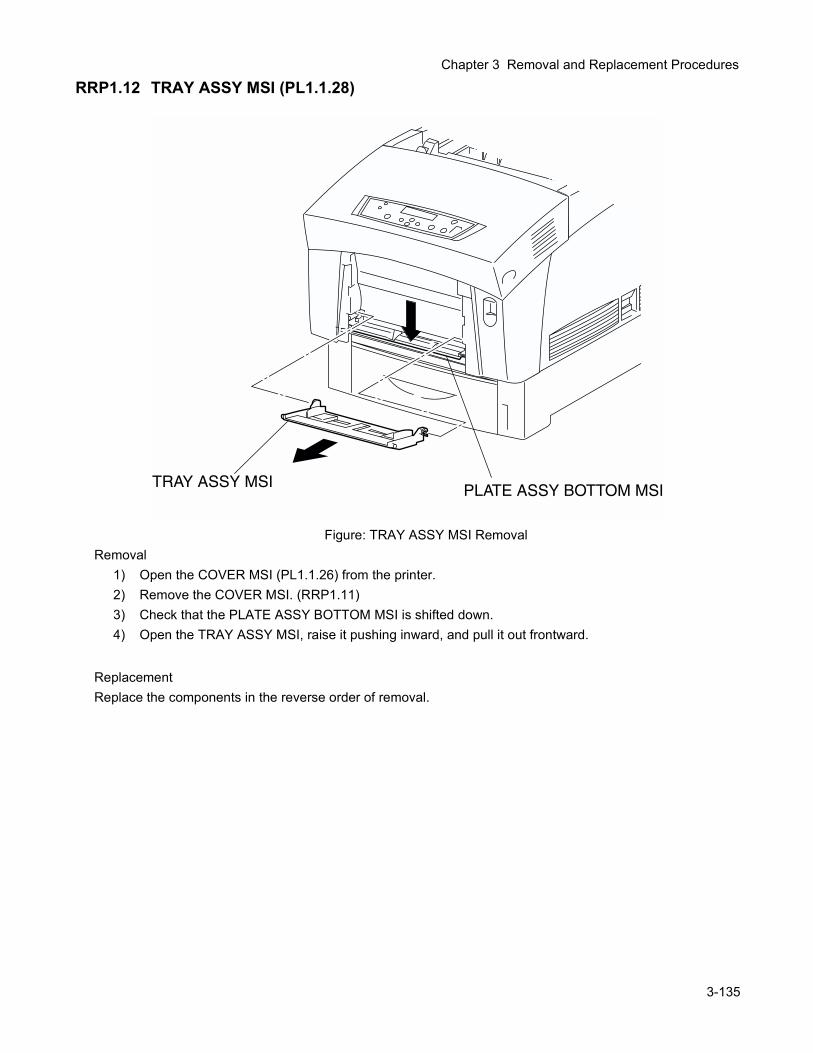
Chapter 3 Removal and Replacement Procedures
RRP1.12 TRAY ASSY MSI (PL1.1.28)
Figure: TRAY ASSY MSI RemovalRemoval
1) Open the COVER MSI (PL1.1.26) from the printer.2) Remove the COVER MSI. (RRP1.11)3) Check that the PLATE ASSY BOTTOM MSI is shifted down.4) Open the TRAY ASSY MSI, raise it pushing inward, and pull it out frontward.
ReplacementReplace the components in the reverse order of removal.
3-135
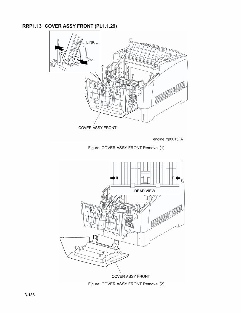
RRP1.13 COVER ASSY FRONT (PL1.1.29)
Figure: COVER ASSY FRONT Removal (1)
Figure: COVER ASSY FRONT Removal (2)
3-136
Chapter 3 Removal and Replacement Procedures
Removal1) Remove the COVER MSI. (RRP1.11)2) Remove the TRAY ASSY MSI. (RRP1.12)3) Remove the ASSY FRONT IN RRP. (RRP 1.10)4) Release the strap from the CHUTE ASSY IN. (RRP 5.1)5) Remove the COVER ASSY FRONT HEAD. (RRP1.2)6) Release the latch at B from the printer and open the CHUTE ASSY OUT.7) Shift the pin at the tip of the LINK:L (PL1.1.23) from the leaf spring at the back of the COVER ASSY
FRONT.8) Remove 2 screws securing the COVER ASSY FRONT to the CHUTE ASSY OUT (PL6.1.1). 9) Release the hooks securing the COVER ASSY FRONT at 2 positions to the CHUTE ASSY OUT.10) Remove the COVER ASSY FRONT from the CHUTE ASSY OUT.
ReplacementReplace the components in the reverse order of removal.
3-137
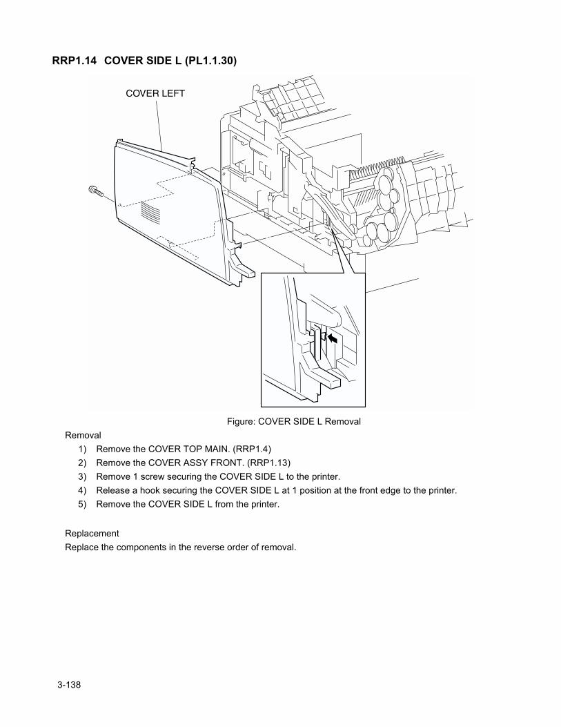
RRP1.14 COVER SIDE L (PL1.1.30)
Figure: COVER SIDE L RemovalRemoval
1) Remove the COVER TOP MAIN. (RRP1.4)2) Remove the COVER ASSY FRONT. (RRP1.13)3) Remove 1 screw securing the COVER SIDE L to the printer.4) Release a hook securing the COVER SIDE L at 1 position at the front edge to the printer.5) Remove the COVER SIDE L from the printer.
ReplacementReplace the components in the reverse order of removal.
3-138
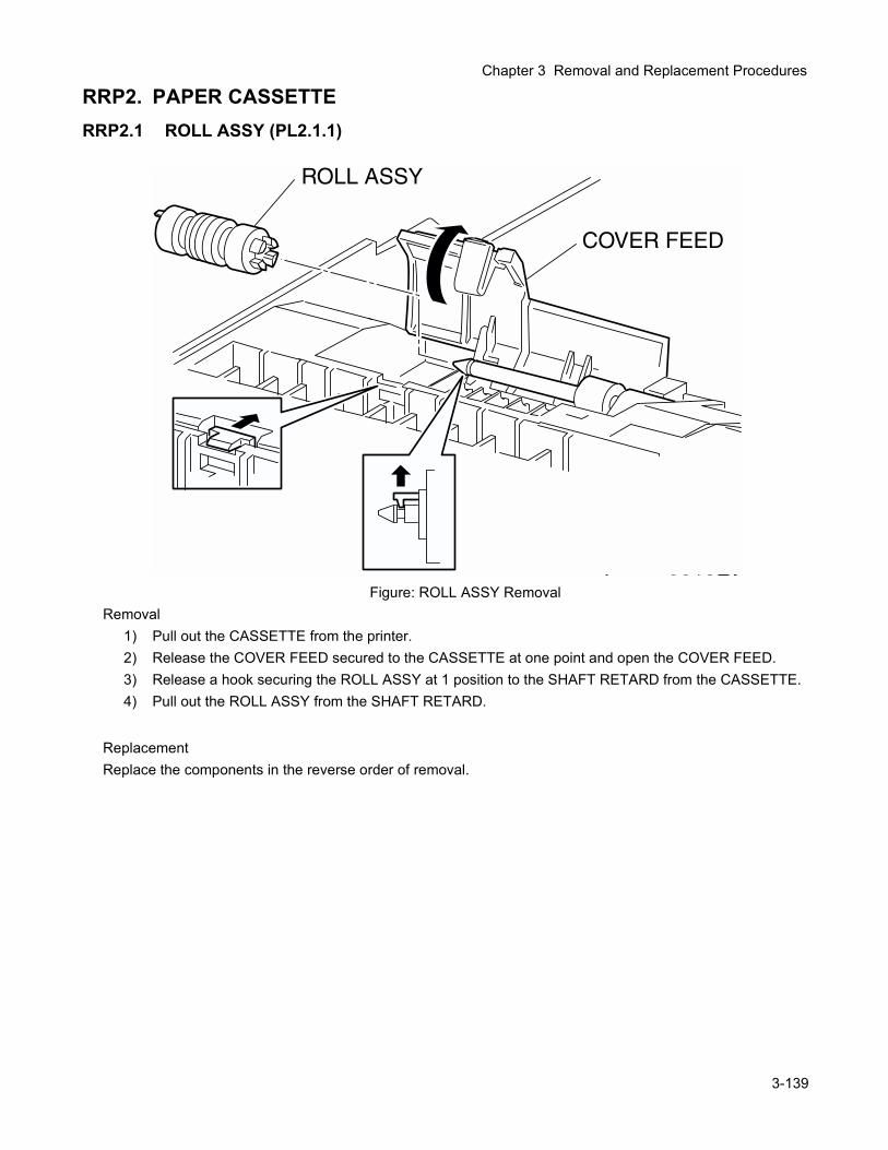
Chapter 3 Removal and Replacement Procedures
RRP2. PAPER CASSETTERRP2.1 ROLL ASSY (PL2.1.1)
Figure: ROLL ASSY RemovalRemoval
1) Pull out the CASSETTE from the printer.2) Release the COVER FEED secured to the CASSETTE at one point and open the COVER FEED.3) Release a hook securing the ROLL ASSY at 1 position to the SHAFT RETARD from the CASSETTE. 4) Pull out the ROLL ASSY from the SHAFT RETARD.
ReplacementReplace the components in the reverse order of removal.
3-139
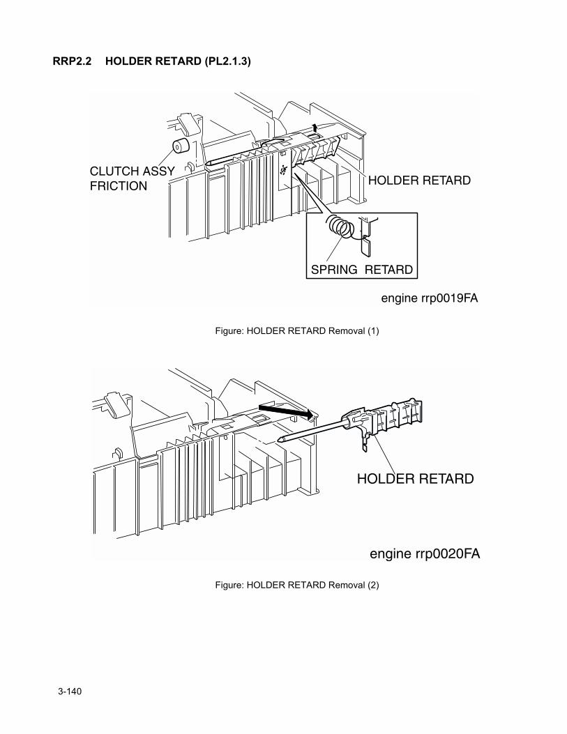
RRP2.2 HOLDER RETARD (PL2.1.3)
Figure: HOLDER RETARD Removal (1)
Figure: HOLDER RETARD Removal (2)
3-140
Chapter 3 Removal and Replacement Procedures
Removal1) Pull out the CASSETTE from the printer.2) Remove the CASSETTE ASSY FRONT. (RRP2.3)3) Remove the ROLL ASSY. (RRP2.1)4) Pull out the CLUTCH ASSY FRICTION (PL2.1.2) on the SHAFT RETARD from the CASSETTE.5) Release the hook of the SPRING RETARD (2.1.4) hitched to the bottom groove of the HOLDER
RETARD from the CASSETTE.6) Release the hook at 1 position securing the top portion of the HOLDER RETARD from the CASSETTE
and move the HOLDER RETARD leftward.7) Pull out the right end of the HOLDER RETARD slightly from the CASSETTE and extract the HOLDER
RETARD and remove.
ReplacementReplace the components in the reverse order of removal.
3-141
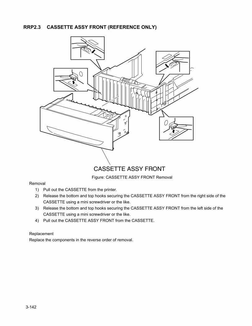
RRP2.3 CASSETTE ASSY FRONT (REFERENCE ONLY)
Figure: CASSETTE ASSY FRONT RemovalRemoval
1) Pull out the CASSETTE from the printer.2) Release the bottom and top hooks securing the CASSETTE ASSY FRONT from the right side of the
CASSETTE using a mini screwdriver or the like.3) Release the bottom and top hooks securing the CASSETTE ASSY FRONT from the left side of the
CASSETTE using a mini screwdriver or the like.4) Pull out the CASSETTE ASSY FRONT from the CASSETTE.
ReplacementReplace the components in the reverse order of removal.
3-142

Chapter 3 Removal and Replacement Procedures
3-143
Blank page.
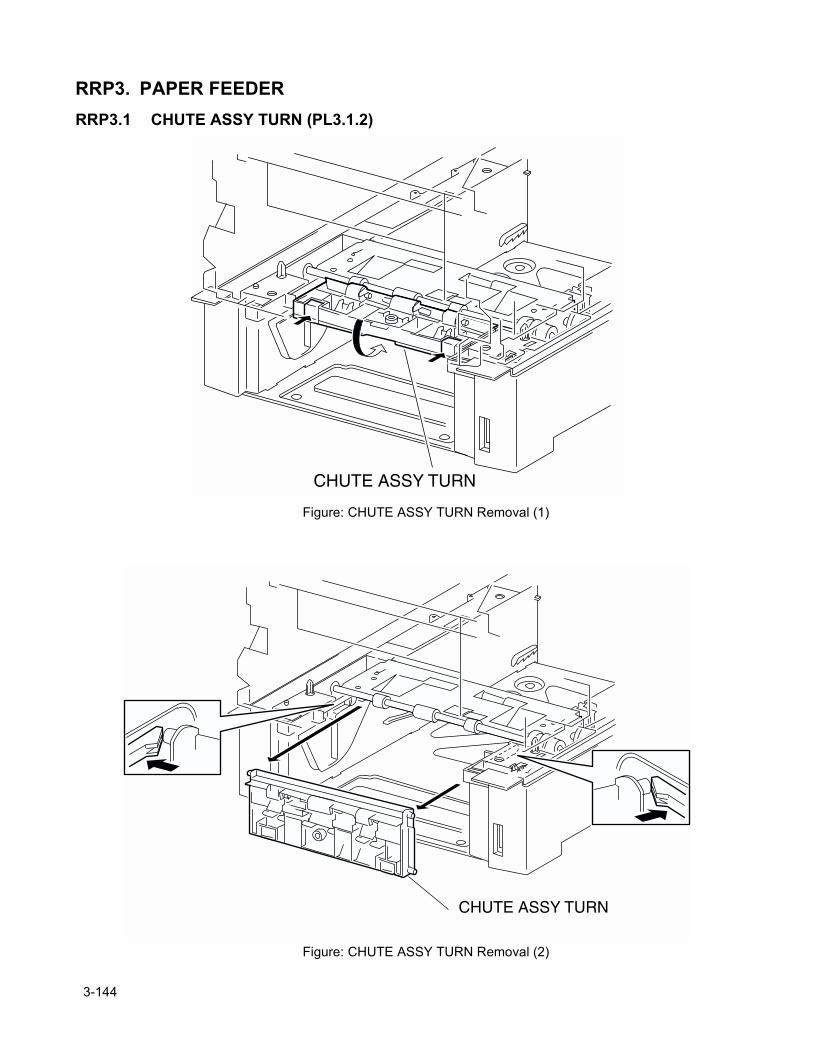
RRP3. PAPER FEEDERRRP3.1 CHUTE ASSY TURN (PL3.1.2)
Figure: CHUTE ASSY TURN Removal (1)
Figure: CHUTE ASSY TURN Removal (2)
3-144
Chapter 3 Removal and Replacement Procedures
Removal1) Pull out the CASSETTE from the printer.2) Release the hooks at 2 positions securing the CHUTE ASSY TURN to the printer FEEDER.3) Turn the CHUTE ASSY 90 degrees rearward from the printer FEEDER.4) Release the hook securing the right and left shaft of the CHUTE ASSY TURN to the printer FEEDER.5) Pull out the CHUTE ASSY TURN from the printer FEEDER and remove.
ReplacementReplace the components in the reverse order of removal.
3-145
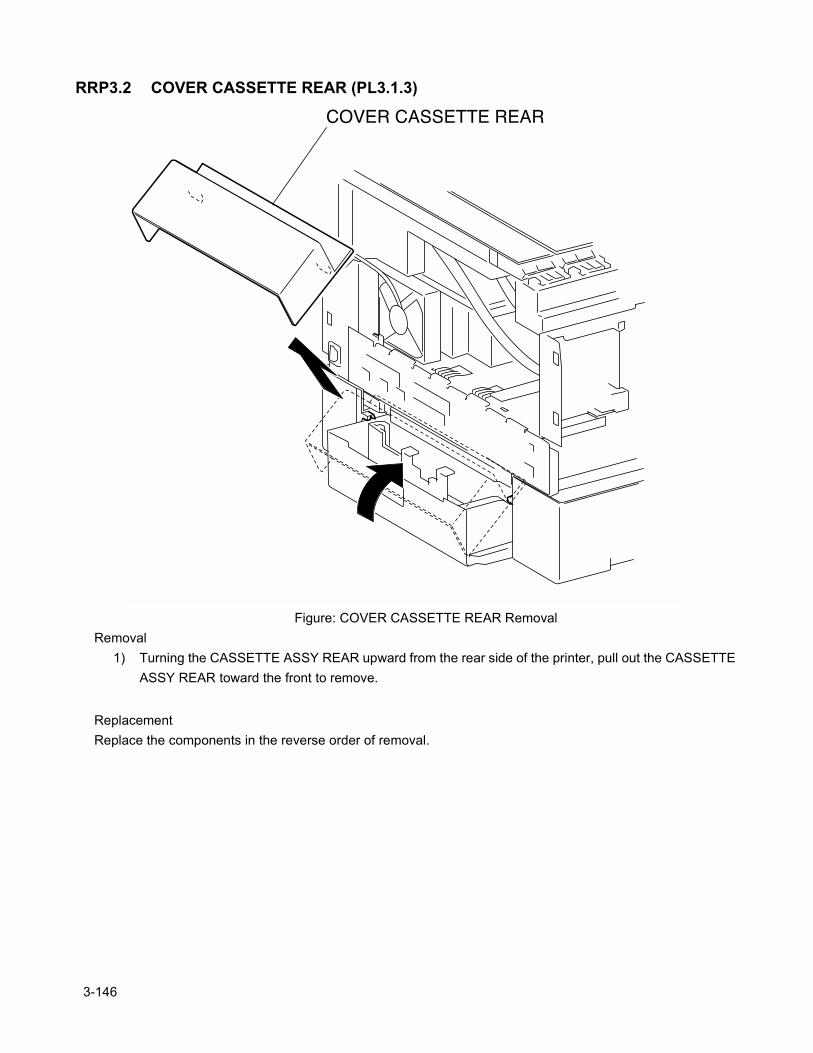
RRP3.2 COVER CASSETTE REAR (PL3.1.3)
Figure: COVER CASSETTE REAR RemovalRemoval
1) Turning the CASSETTE ASSY REAR upward from the rear side of the printer, pull out the CASSETTE ASSY REAR toward the front to remove.
ReplacementReplace the components in the reverse order of removal.
3-146

Chapter 3 Removal and Replacement Procedures
3-147
Blank page.
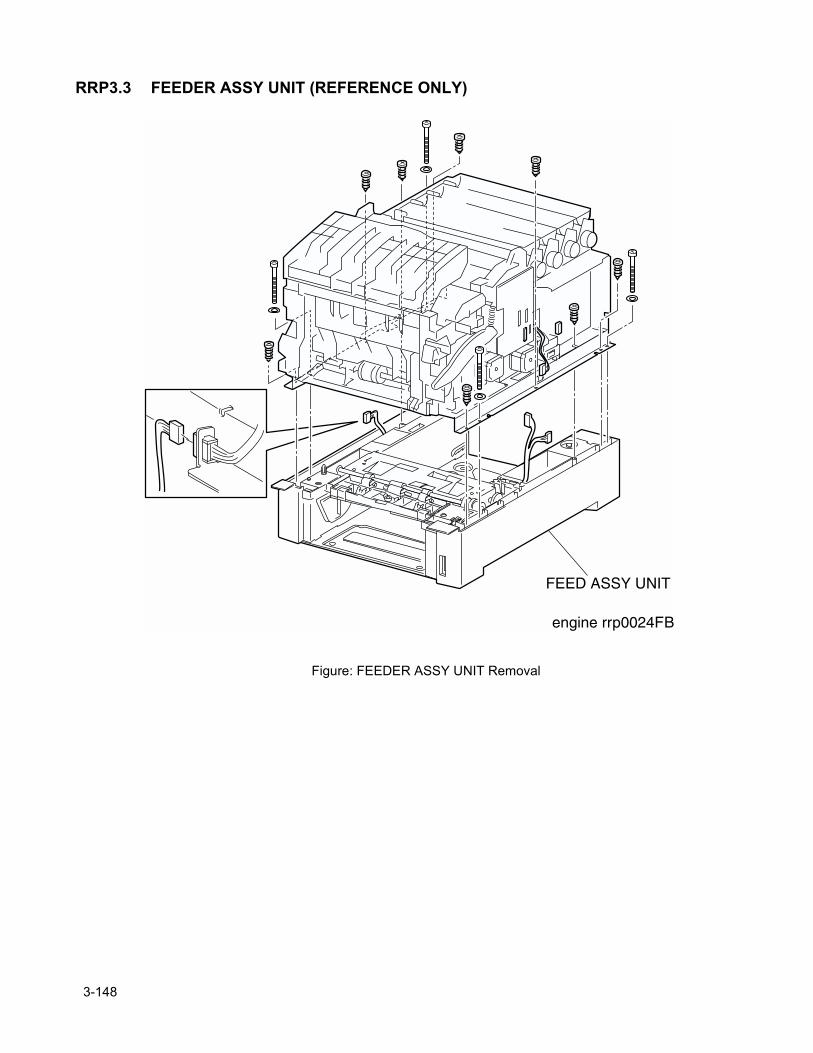
RRP3.3 FEEDER ASSY UNIT (REFERENCE ONLY)
Figure: FEEDER ASSY UNIT Removal
3-148
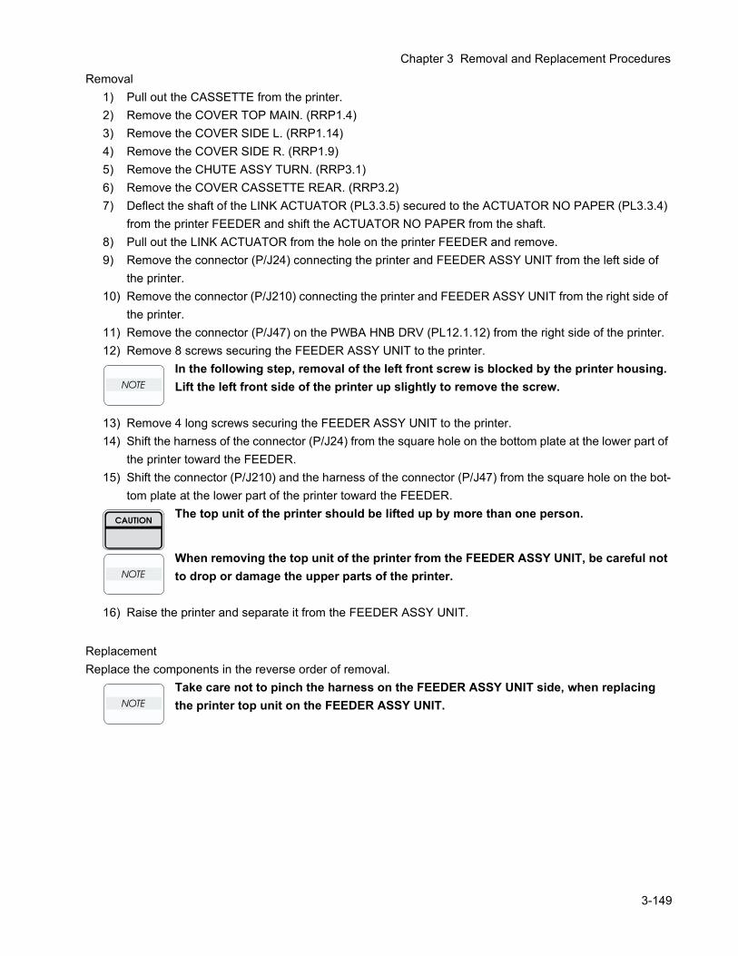
Chapter 3 Removal and Replacement Procedures
Removal1) Pull out the CASSETTE from the printer.2) Remove the COVER TOP MAIN. (RRP1.4)3) Remove the COVER SIDE L. (RRP1.14)4) Remove the COVER SIDE R. (RRP1.9)5) Remove the CHUTE ASSY TURN. (RRP3.1)6) Remove the COVER CASSETTE REAR. (RRP3.2)7) Deflect the shaft of the LINK ACTUATOR (PL3.3.5) secured to the ACTUATOR NO PAPER (PL3.3.4)
from the printer FEEDER and shift the ACTUATOR NO PAPER from the shaft.8) Pull out the LINK ACTUATOR from the hole on the printer FEEDER and remove.9) Remove the connector (P/J24) connecting the printer and FEEDER ASSY UNIT from the left side of
the printer.10) Remove the connector (P/J210) connecting the printer and FEEDER ASSY UNIT from the right side of
the printer.11) Remove the connector (P/J47) on the PWBA HNB DRV (PL12.1.12) from the right side of the printer.12) Remove 8 screws securing the FEEDER ASSY UNIT to the printer.
In the following step, removal of the left front screw is blocked by the printer housing. Lift the left front side of the printer up slightly to remove the screw.
13) Remove 4 long screws securing the FEEDER ASSY UNIT to the printer.14) Shift the harness of the connector (P/J24) from the square hole on the bottom plate at the lower part of
the printer toward the FEEDER.15) Shift the connector (P/J210) and the harness of the connector (P/J47) from the square hole on the bot-
tom plate at the lower part of the printer toward the FEEDER.The top unit of the printer should be lifted up by more than one person.
When removing the top unit of the printer from the FEEDER ASSY UNIT, be careful not to drop or damage the upper parts of the printer.
16) Raise the printer and separate it from the FEEDER ASSY UNIT.
ReplacementReplace the components in the reverse order of removal.
Take care not to pinch the harness on the FEEDER ASSY UNIT side, when replacing the printer top unit on the FEEDER ASSY UNIT.
3-149
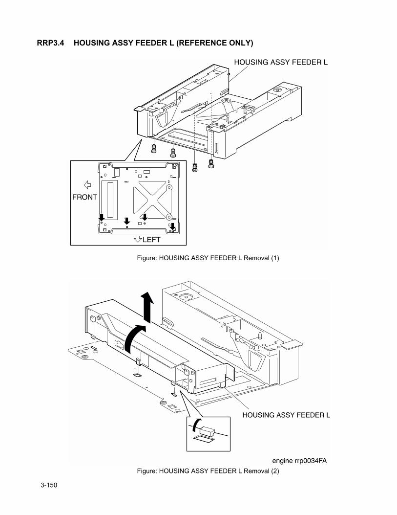
RRP3.4 HOUSING ASSY FEEDER L (REFERENCE ONLY)
Figure: HOUSING ASSY FEEDER L Removal (1)
Figure: HOUSING ASSY FEEDER L Removal (2)
3-150

Chapter 3 Removal and Replacement Procedures
Removal1) Pull out the CASSETTE from the printer.2) Remove the COVER TOP MAIN. (RRP1.4)3) Remove the COVER SIDE L. (RRP1.14)4) Remove the COVER SIDE R. (RRP1.9)5) Remove the CHUTE ASSY TURN. (RRP3.1)6) Remove the COVER CASSETTE REAR. (RRP3.2)7) Remove the FEEDER ASSY UNIT. (RRP3.3)8) Remove the PICKUP ASSY. (RRP3.12)9) Remove 4 screws securing the HOUSING ASSY FEEDER L to the PLATE BOTTOM.10) Pull down the HOUSING ASSY FEEDER L inward and extract the hooks at 3 positions out of the hole
at the PLATE BOTTOM.11) Remove the HOUSING ASSY FEEDER L upward from the PLATE BOTTOM.
ReplacementReplace the components in the reverse order of removal.
3-151
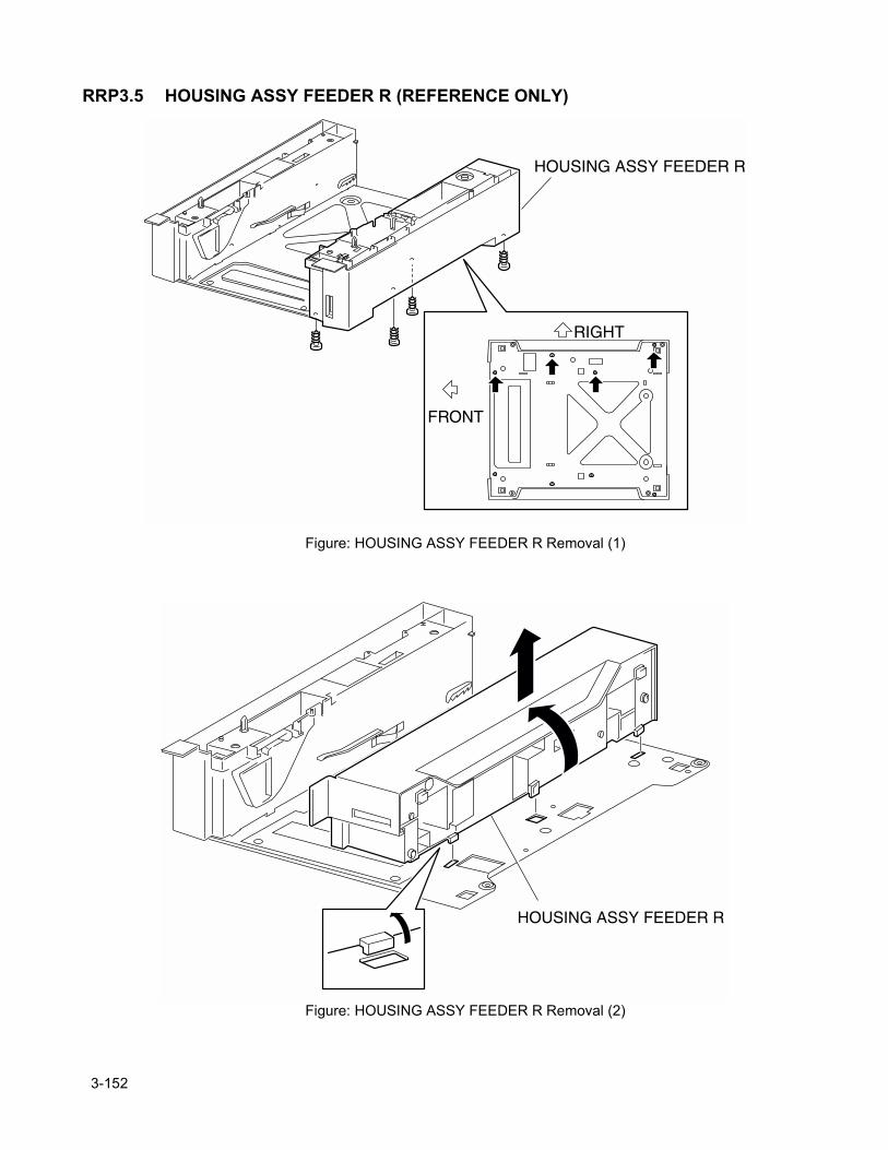
RRP3.5 HOUSING ASSY FEEDER R (REFERENCE ONLY)
Figure: HOUSING ASSY FEEDER R Removal (1)
Figure: HOUSING ASSY FEEDER R Removal (2)
3-152
Chapter 3 Removal and Replacement Procedures
Removal1) Pull out the CASSETTE from the printer.2) Remove the COVER TOP MAIN. (RRP1.4)3) Remove the COVER SIDE L. (RRP1.14)4) Remove the COVER SIDE R. (RRP1.9)5) Remove the CHUTE ASSY TURN. (RRP3.1)6) Remove the COVER CASSETTE REAR. (RRP3.2)7) Remove the FEEDER ASSY UNIT. (RRP3.3)8) Remove the PICKUP ASSY. (RRP3.12)9) Remove 4 screws securing the SUPPORT FEEDER LEFT to the PLATE BOTTOM.10) Pull down the HOUSING ASSY FEEDER R inward and extract the hooks at 3 positions out of the hole
at the PLATE BOTTOM.11) Remove the HOUSING ASSY FEEDER R upward from the PLATE BOTTOM.
ReplacementReplace the components in the reverse order of removal.
3-153
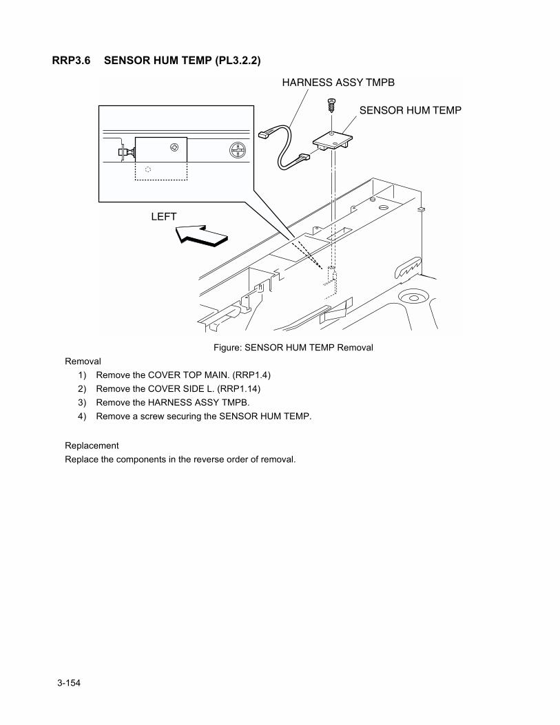
RRP3.6 SENSOR HUM TEMP (PL3.2.2)
Figure: SENSOR HUM TEMP RemovalRemoval
1) Remove the COVER TOP MAIN. (RRP1.4)2) Remove the COVER SIDE L. (RRP1.14)3) Remove the HARNESS ASSY TMPB.4) Remove a screw securing the SENSOR HUM TEMP.
ReplacementReplace the components in the reverse order of removal.
3-154
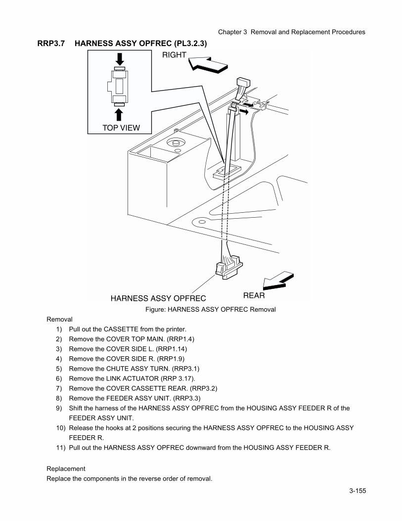
Chapter 3 Removal and Replacement Procedures
RRP3.7 HARNESS ASSY OPFREC (PL3.2.3)
Figure: HARNESS ASSY OPFREC RemovalRemoval
1) Pull out the CASSETTE from the printer.2) Remove the COVER TOP MAIN. (RRP1.4)3) Remove the COVER SIDE L. (RRP1.14)4) Remove the COVER SIDE R. (RRP1.9)5) Remove the CHUTE ASSY TURN. (RRP3.1)6) Remove the LINK ACTUATOR (RRP 3.17).7) Remove the COVER CASSETTE REAR. (RRP3.2)8) Remove the FEEDER ASSY UNIT. (RRP3.3)9) Shift the harness of the HARNESS ASSY OPFREC from the HOUSING ASSY FEEDER R of the
FEEDER ASSY UNIT. 10) Release the hooks at 2 positions securing the HARNESS ASSY OPFREC to the HOUSING ASSY
FEEDER R.11) Pull out the HARNESS ASSY OPFREC downward from the HOUSING ASSY FEEDER R.
ReplacementReplace the components in the reverse order of removal.
3-155
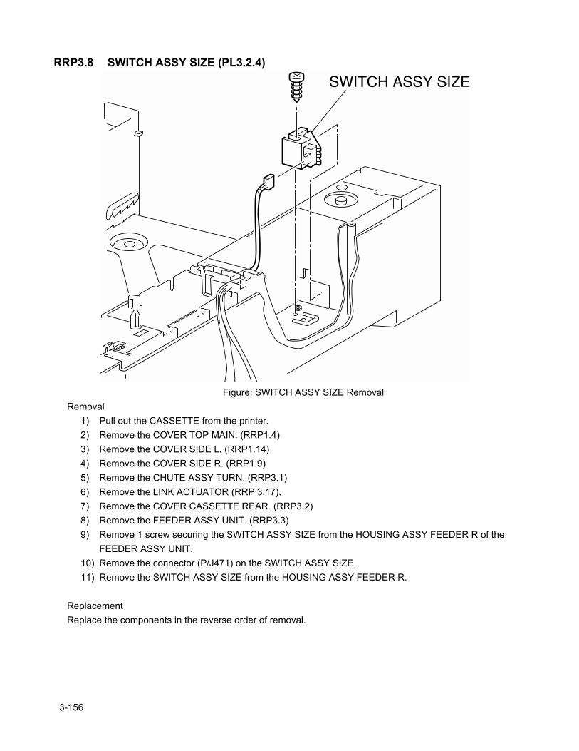
RRP3.8 SWITCH ASSY SIZE (PL3.2.4)
Figure: SWITCH ASSY SIZE RemovalRemoval
1) Pull out the CASSETTE from the printer.2) Remove the COVER TOP MAIN. (RRP1.4)3) Remove the COVER SIDE L. (RRP1.14)4) Remove the COVER SIDE R. (RRP1.9)5) Remove the CHUTE ASSY TURN. (RRP3.1)6) Remove the LINK ACTUATOR (RRP 3.17).7) Remove the COVER CASSETTE REAR. (RRP3.2)8) Remove the FEEDER ASSY UNIT. (RRP3.3)9) Remove 1 screw securing the SWITCH ASSY SIZE from the HOUSING ASSY FEEDER R of the
FEEDER ASSY UNIT.10) Remove the connector (P/J471) on the SWITCH ASSY SIZE.11) Remove the SWITCH ASSY SIZE from the HOUSING ASSY FEEDER R.
ReplacementReplace the components in the reverse order of removal.
3-156

Chapter 3 Removal and Replacement Procedures
3-157
Blank page.
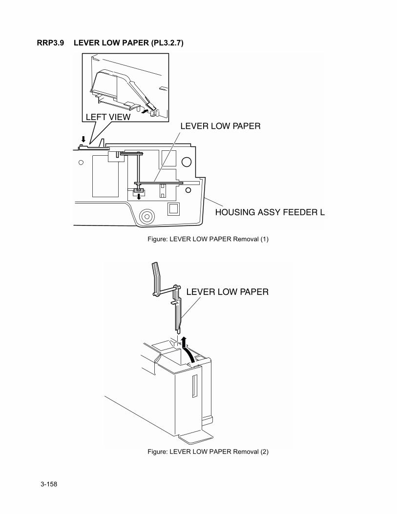
RRP3.9 LEVER LOW PAPER (PL3.2.7)
Figure: LEVER LOW PAPER Removal (1)
Figure: LEVER LOW PAPER Removal (2)
3-158
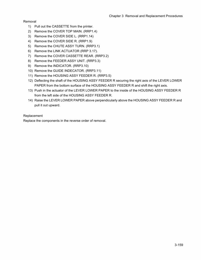
Chapter 3 Removal and Replacement Procedures
Removal1) Pull out the CASSETTE from the printer.2) Remove the COVER TOP MAIN. (RRP1.4)3) Remove the COVER SIDE L. (RRP1.14)4) Remove the COVER SIDE R. (RRP1.9)5) Remove the CHUTE ASSY TURN. (RRP3.1)6) Remove the LINK ACTUATOR (RRP 3.17).7) Remove the COVER CASSETTE REAR. (RRP3.2)8) Remove the FEEDER ASSY UNIT. (RRP3.3)9) Remove the INDICATOR. (RRP3.10)10) Remove the GUIDE INDECATOR. (RRP3.11)11) Remove the HOUSING ASSY FEEDER R. (RRP3.5)12) Deflecting the shaft of the HOUSING ASSY FEEDER R securing the right axis of the LEVER LOWER
PAPER from the bottom surface of the HOUSING ASSY FEEDER R and shift the right axis.13) Push in the actuator of the LEVER LOWER PAPER to the inside of the HOUSING ASSY FEEDER R
from the left side of the HOUSING ASSY FEEDER R.14) Raise the LEVER LOWER PAPER above perpendicularly above the HOUSING ASSY FEEDER R and
pull it out upward.
ReplacementReplace the components in the reverse order of removal.
3-159
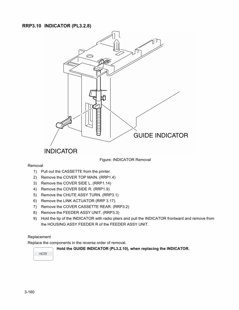
RRP3.10 INDICATOR (PL3.2.8)
Figure: INDICATOR RemovalRemoval
1) Pull out the CASSETTE from the printer.2) Remove the COVER TOP MAIN. (RRP1.4)3) Remove the COVER SIDE L. (RRP1.14)4) Remove the COVER SIDE R. (RRP1.9)5) Remove the CHUTE ASSY TURN. (RRP3.1)6) Remove the LINK ACTUATOR (RRP 3.17).7) Remove the COVER CASSETTE REAR. (RRP3.2)8) Remove the FEEDER ASSY UNIT. (RRP3.3)9) Hold the tip of the INDICATOR with radio pliers and pull the INDICATOR frontward and remove from
the HOUSING ASSY FEEDER R of the FEEDER ASSY UNIT.
ReplacementReplace the components in the reverse order of removal.
Hold the GUIDE INDICATOR (PL3.2.10), when replacing the INDICATOR.
3-160

Chapter 3 Removal and Replacement Procedures
3-161
Blank page.
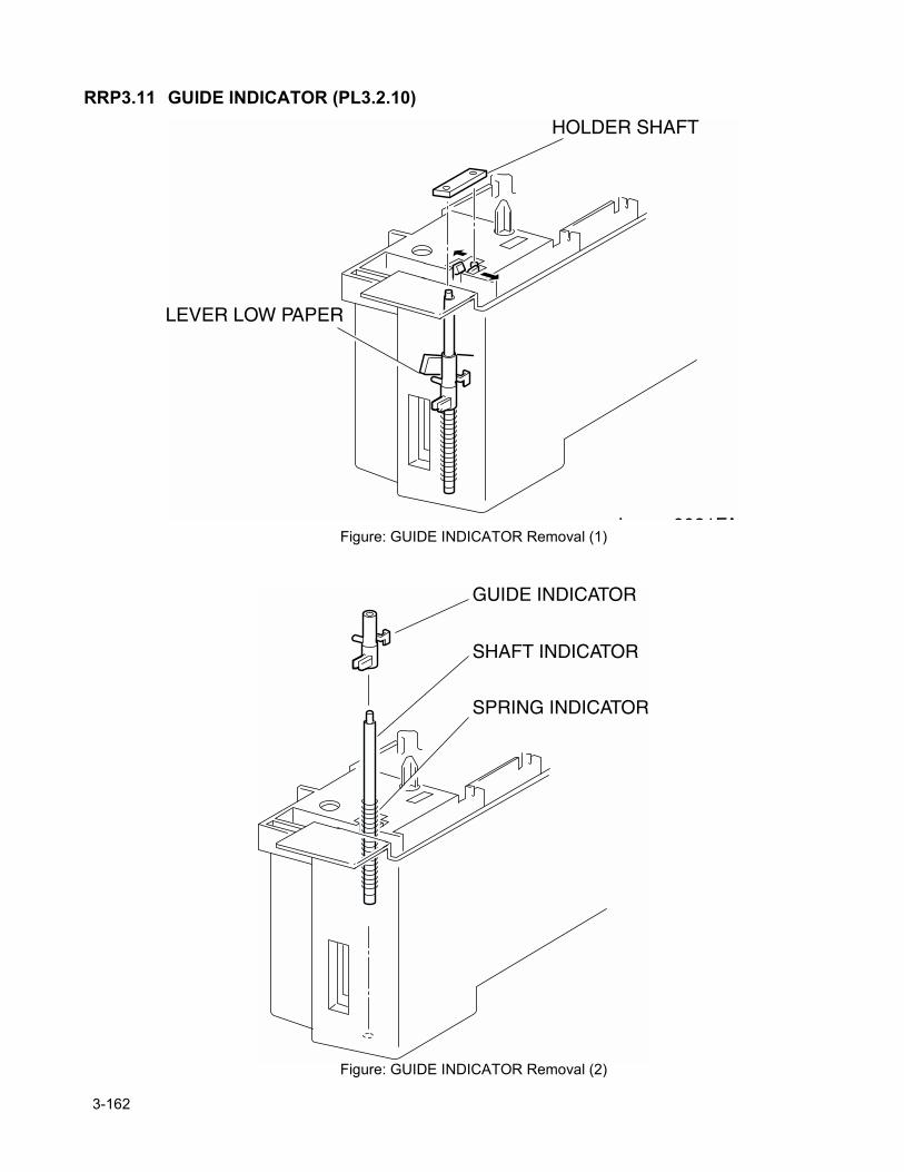
RRP3.11 GUIDE INDICATOR (PL3.2.10)
Figure: GUIDE INDICATOR Removal (1)
Figure: GUIDE INDICATOR Removal (2)
3-162
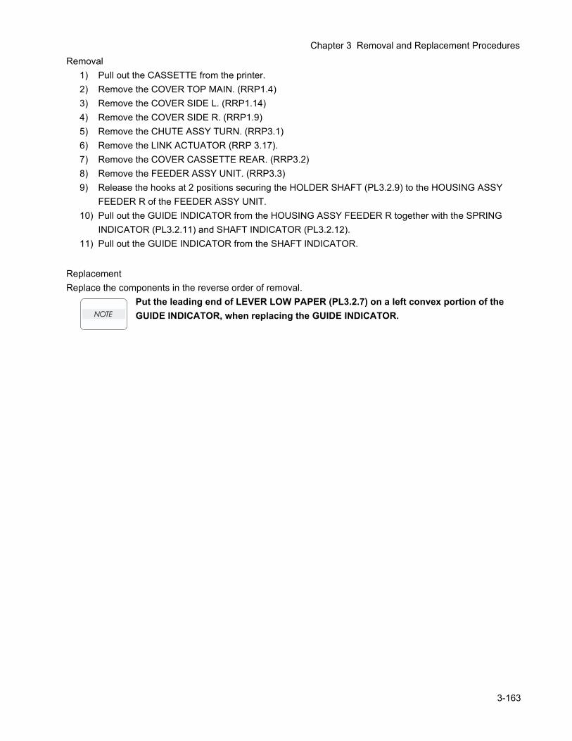
Chapter 3 Removal and Replacement Procedures
Removal1) Pull out the CASSETTE from the printer.2) Remove the COVER TOP MAIN. (RRP1.4)3) Remove the COVER SIDE L. (RRP1.14)4) Remove the COVER SIDE R. (RRP1.9)5) Remove the CHUTE ASSY TURN. (RRP3.1)6) Remove the LINK ACTUATOR (RRP 3.17).7) Remove the COVER CASSETTE REAR. (RRP3.2)8) Remove the FEEDER ASSY UNIT. (RRP3.3)9) Release the hooks at 2 positions securing the HOLDER SHAFT (PL3.2.9) to the HOUSING ASSY
FEEDER R of the FEEDER ASSY UNIT.10) Pull out the GUIDE INDICATOR from the HOUSING ASSY FEEDER R together with the SPRING
INDICATOR (PL3.2.11) and SHAFT INDICATOR (PL3.2.12).11) Pull out the GUIDE INDICATOR from the SHAFT INDICATOR.
ReplacementReplace the components in the reverse order of removal.
Put the leading end of LEVER LOW PAPER (PL3.2.7) on a left convex portion of the GUIDE INDICATOR, when replacing the GUIDE INDICATOR.
3-163
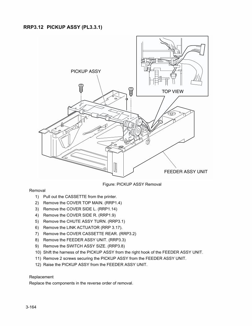
RRP3.12 PICKUP ASSY (PL3.3.1)
Figure: PICKUP ASSY RemovalRemoval
1) Pull out the CASSETTE from the printer.2) Remove the COVER TOP MAIN. (RRP1.4)3) Remove the COVER SIDE L. (RRP1.14)4) Remove the COVER SIDE R. (RRP1.9)5) Remove the CHUTE ASSY TURN. (RRP3.1)6) Remove the LINK ACTUATOR (RRP 3.17).7) Remove the COVER CASSETTE REAR. (RRP3.2)8) Remove the FEEDER ASSY UNIT. (RRP3.3)9) Remove the SWITCH ASSY SIZE. (RRP3.8)10) Shift the harness of the PICKUP ASSY from the right hook of the FEEDER ASSY UNIT.11) Remove 2 screws securing the PICKUP ASSY from the FEEDER ASSY UNIT.12) Raise the PICKUP ASSY from the FEEDER ASSY UNIT.
ReplacementReplace the components in the reverse order of removal.
3-164

Chapter 3 Removal and Replacement Procedures
3-165
Blank page.
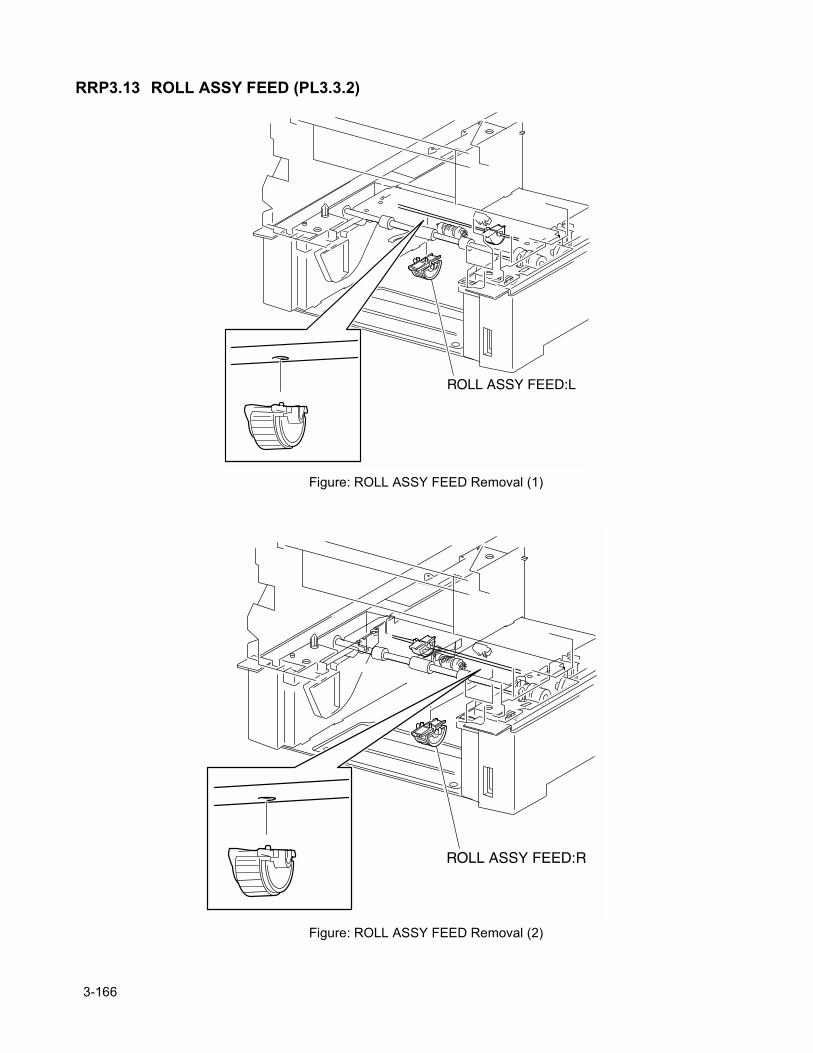
RRP3.13 ROLL ASSY FEED (PL3.3.2)
Figure: ROLL ASSY FEED Removal (1)
Figure: ROLL ASSY FEED Removal (2)
3-166
Chapter 3 Removal and Replacement Procedures
Removal1) Pull out the CASSETTE from the printer.2) Remove the CHUTE ASSY TURN. (RRP3.1)
In the following steps, replace and remove the ROLL ASSY FEED, unilateral at a time, to confirm the replacing direction of the ROLL ASSY FEED.
3) Rotate the SHAFT FEED 1 (PL3.3.1) so that the rubber of the ROLL ASSY FEED faces downward from the printer FEEDER.
4) Release the hook securing the ROLL ASSY FEED to the SHAFT FEED 1 and remove the ROLL ASSY FEED.
ReplacementReplace the components in the reverse order of removal.
3-167
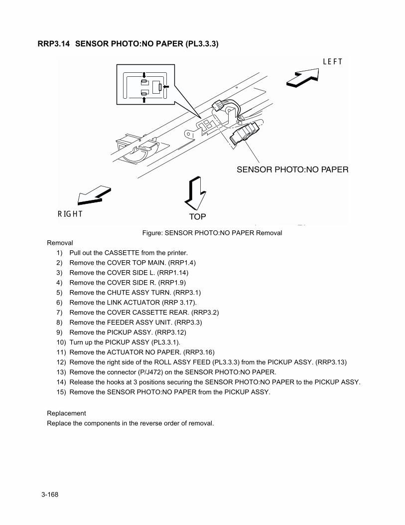
RRP3.14 SENSOR PHOTO:NO PAPER (PL3.3.3)
Figure: SENSOR PHOTO:NO PAPER RemovalRemoval
1) Pull out the CASSETTE from the printer.2) Remove the COVER TOP MAIN. (RRP1.4)3) Remove the COVER SIDE L. (RRP1.14)4) Remove the COVER SIDE R. (RRP1.9)5) Remove the CHUTE ASSY TURN. (RRP3.1)6) Remove the LINK ACTUATOR (RRP 3.17).7) Remove the COVER CASSETTE REAR. (RRP3.2)8) Remove the FEEDER ASSY UNIT. (RRP3.3)9) Remove the PICKUP ASSY. (RRP3.12)10) Turn up the PICKUP ASSY (PL3.3.1).11) Remove the ACTUATOR NO PAPER. (RRP3.16)12) Remove the right side of the ROLL ASSY FEED (PL3.3.3) from the PICKUP ASSY. (RRP3.13)13) Remove the connector (P/J472) on the SENSOR PHOTO:NO PAPER.14) Release the hooks at 3 positions securing the SENSOR PHOTO:NO PAPER to the PICKUP ASSY.15) Remove the SENSOR PHOTO:NO PAPER from the PICKUP ASSY.
ReplacementReplace the components in the reverse order of removal.
RIGHT
LEFT
3-168
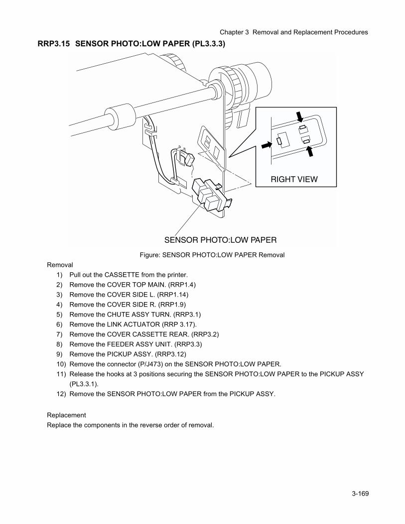
Chapter 3 Removal and Replacement Procedures
RRP3.15 SENSOR PHOTO:LOW PAPER (PL3.3.3)
Figure: SENSOR PHOTO:LOW PAPER RemovalRemoval
1) Pull out the CASSETTE from the printer.2) Remove the COVER TOP MAIN. (RRP1.4)3) Remove the COVER SIDE L. (RRP1.14)4) Remove the COVER SIDE R. (RRP1.9)5) Remove the CHUTE ASSY TURN. (RRP3.1)6) Remove the LINK ACTUATOR (RRP 3.17).7) Remove the COVER CASSETTE REAR. (RRP3.2)8) Remove the FEEDER ASSY UNIT. (RRP3.3)9) Remove the PICKUP ASSY. (RRP3.12)10) Remove the connector (P/J473) on the SENSOR PHOTO:LOW PAPER.11) Release the hooks at 3 positions securing the SENSOR PHOTO:LOW PAPER to the PICKUP ASSY
(PL3.3.1).12) Remove the SENSOR PHOTO:LOW PAPER from the PICKUP ASSY.
ReplacementReplace the components in the reverse order of removal.
3-169
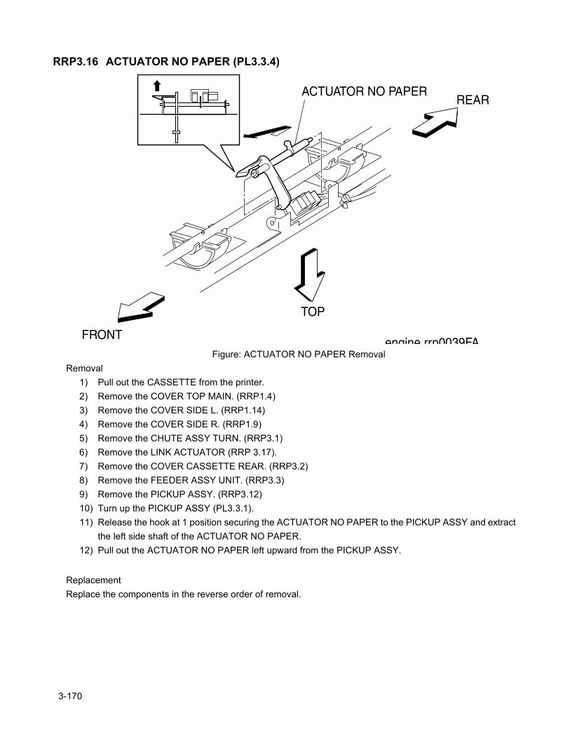
RRP3.16 ACTUATOR NO PAPER (PL3.3.4)
Figure: ACTUATOR NO PAPER RemovalRemoval
1) Pull out the CASSETTE from the printer.2) Remove the COVER TOP MAIN. (RRP1.4)3) Remove the COVER SIDE L. (RRP1.14)4) Remove the COVER SIDE R. (RRP1.9)5) Remove the CHUTE ASSY TURN. (RRP3.1)6) Remove the LINK ACTUATOR (RRP 3.17).7) Remove the COVER CASSETTE REAR. (RRP3.2)8) Remove the FEEDER ASSY UNIT. (RRP3.3)9) Remove the PICKUP ASSY. (RRP3.12)10) Turn up the PICKUP ASSY (PL3.3.1).11) Release the hook at 1 position securing the ACTUATOR NO PAPER to the PICKUP ASSY and extract
the left side shaft of the ACTUATOR NO PAPER.12) Pull out the ACTUATOR NO PAPER left upward from the PICKUP ASSY.
ReplacementReplace the components in the reverse order of removal.
3-170
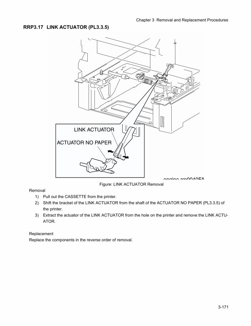
Chapter 3 Removal and Replacement Procedures
RRP3.17 LINK ACTUATOR (PL3.3.5)
Figure: LINK ACTUATOR RemovalRemoval
1) Pull out the CASSETTE from the printer.2) Shift the bracket of the LINK ACTUATOR from the shaft of the ACTUATOR NO PAPER (PL3.3.5) of
the printer.3) Extract the actuator of the LINK ACTUATOR from the hole on the printer and remove the LINK ACTU-
ATOR.
ReplacementReplace the components in the reverse order of removal.
3-171
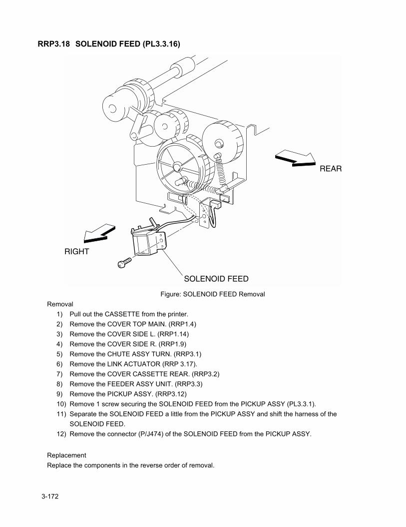
RRP3.18 SOLENOID FEED (PL3.3.16)
Figure: SOLENOID FEED RemovalRemoval
1) Pull out the CASSETTE from the printer.2) Remove the COVER TOP MAIN. (RRP1.4)3) Remove the COVER SIDE L. (RRP1.14)4) Remove the COVER SIDE R. (RRP1.9)5) Remove the CHUTE ASSY TURN. (RRP3.1)6) Remove the LINK ACTUATOR (RRP 3.17).7) Remove the COVER CASSETTE REAR. (RRP3.2)8) Remove the FEEDER ASSY UNIT. (RRP3.3)9) Remove the PICKUP ASSY. (RRP3.12)10) Remove 1 screw securing the SOLENOID FEED from the PICKUP ASSY (PL3.3.1).11) Separate the SOLENOID FEED a little from the PICKUP ASSY and shift the harness of the
SOLENOID FEED.12) Remove the connector (P/J474) of the SOLENOID FEED from the PICKUP ASSY.
ReplacementReplace the components in the reverse order of removal.
3-172
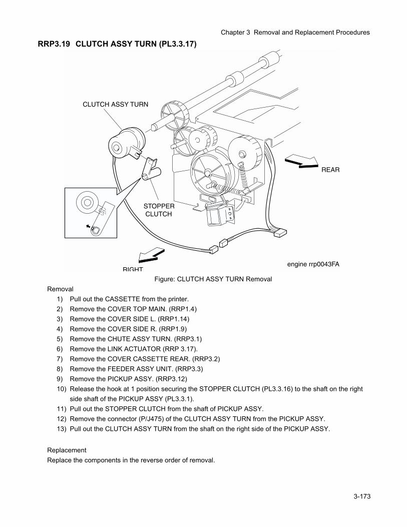
Chapter 3 Removal and Replacement Procedures
RRP3.19 CLUTCH ASSY TURN (PL3.3.17)
Figure: CLUTCH ASSY TURN RemovalRemoval
1) Pull out the CASSETTE from the printer.2) Remove the COVER TOP MAIN. (RRP1.4)3) Remove the COVER SIDE L. (RRP1.14)4) Remove the COVER SIDE R. (RRP1.9)5) Remove the CHUTE ASSY TURN. (RRP3.1)6) Remove the LINK ACTUATOR (RRP 3.17).7) Remove the COVER CASSETTE REAR. (RRP3.2)8) Remove the FEEDER ASSY UNIT. (RRP3.3)9) Remove the PICKUP ASSY. (RRP3.12)10) Release the hook at 1 position securing the STOPPER CLUTCH (PL3.3.16) to the shaft on the right
side shaft of the PICKUP ASSY (PL3.3.1).11) Pull out the STOPPER CLUTCH from the shaft of PICKUP ASSY.12) Remove the connector (P/J475) of the CLUTCH ASSY TURN from the PICKUP ASSY.13) Pull out the CLUTCH ASSY TURN from the shaft on the right side of the PICKUP ASSY.
ReplacementReplace the components in the reverse order of removal.
3-173
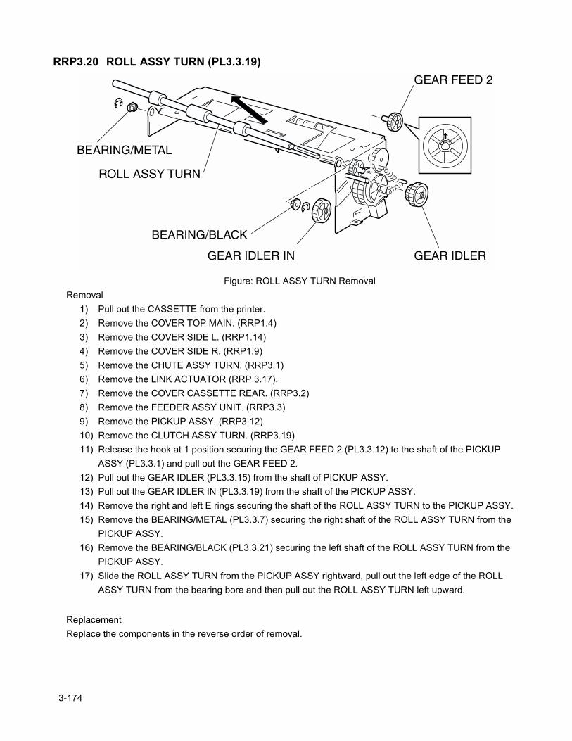
RRP3.20 ROLL ASSY TURN (PL3.3.19)
Figure: ROLL ASSY TURN RemovalRemoval
1) Pull out the CASSETTE from the printer.2) Remove the COVER TOP MAIN. (RRP1.4)3) Remove the COVER SIDE L. (RRP1.14)4) Remove the COVER SIDE R. (RRP1.9)5) Remove the CHUTE ASSY TURN. (RRP3.1)6) Remove the LINK ACTUATOR (RRP 3.17).7) Remove the COVER CASSETTE REAR. (RRP3.2)8) Remove the FEEDER ASSY UNIT. (RRP3.3)9) Remove the PICKUP ASSY. (RRP3.12)10) Remove the CLUTCH ASSY TURN. (RRP3.19)11) Release the hook at 1 position securing the GEAR FEED 2 (PL3.3.12) to the shaft of the PICKUP
ASSY (PL3.3.1) and pull out the GEAR FEED 2.12) Pull out the GEAR IDLER (PL3.3.15) from the shaft of PICKUP ASSY.13) Pull out the GEAR IDLER IN (PL3.3.19) from the shaft of the PICKUP ASSY.14) Remove the right and left E rings securing the shaft of the ROLL ASSY TURN to the PICKUP ASSY.15) Remove the BEARING/METAL (PL3.3.7) securing the right shaft of the ROLL ASSY TURN from the
PICKUP ASSY.16) Remove the BEARING/BLACK (PL3.3.21) securing the left shaft of the ROLL ASSY TURN from the
PICKUP ASSY.17) Slide the ROLL ASSY TURN from the PICKUP ASSY rightward, pull out the left edge of the ROLL
ASSY TURN from the bearing bore and then pull out the ROLL ASSY TURN left upward.
ReplacementReplace the components in the reverse order of removal.
3-174
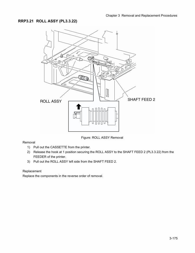
Chapter 3 Removal and Replacement Procedures
RRP3.21 ROLL ASSY (PL3.3.22)
Figure: ROLL ASSY RemovalRemoval
1) Pull out the CASSETTE from the printer.2) Release the hook at 1 position securing the ROLL ASSY to the SHAFT FEED 2 (PL3.3.22) from the
FEEDER of the printer.3) Pull out the ROLL ASSY left side from the SHAFT FEED 2.
ReplacementReplace the components in the reverse order of removal.
3-175
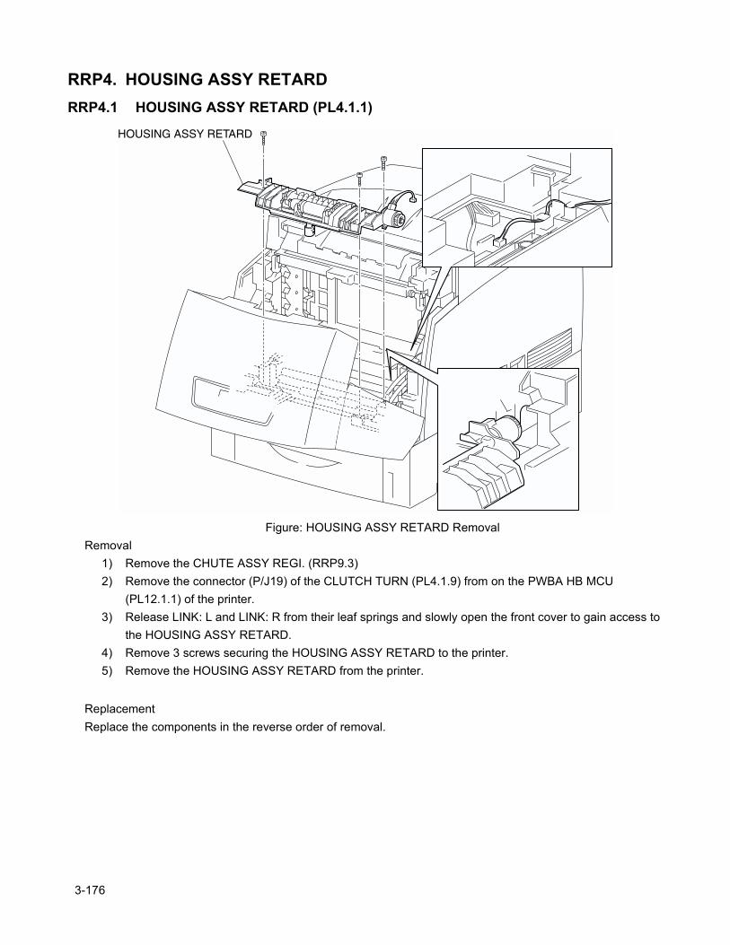
RRP4. HOUSING ASSY RETARDRRP4.1 HOUSING ASSY RETARD (PL4.1.1)
Figure: HOUSING ASSY RETARD RemovalRemoval
1) Remove the CHUTE ASSY REGI. (RRP9.3)2) Remove the connector (P/J19) of the CLUTCH TURN (PL4.1.9) from on the PWBA HB MCU
(PL12.1.1) of the printer.3) Release LINK: L and LINK: R from their leaf springs and slowly open the front cover to gain access to
the HOUSING ASSY RETARD.4) Remove 3 screws securing the HOUSING ASSY RETARD to the printer.5) Remove the HOUSING ASSY RETARD from the printer.
ReplacementReplace the components in the reverse order of removal.
3-176
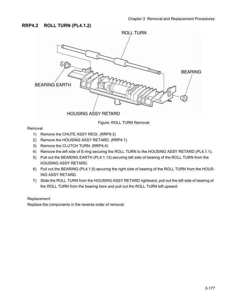
Chapter 3 Removal and Replacement Procedures
RRP4.2 ROLL TURN (PL4.1.2)
Figure: ROLL TURN RemovalRemoval
1) Remove the CHUTE ASSY REGI. (RRP9.3)2) Remove the HOUSING ASSY RETARD. (RRP4.1)3) Remove the CLUTCH TURN. (RRP4.4)4) Remove the left side of E-ring securing the ROLL TURN to the HOUSING ASSY RETARD (PL4.1.1).5) Pull out the BEARING EARTH (PL4.1.13) securing left side of bearing of the ROLL TURN from the
HOUSING ASSY RETARD.6) Pull out the BEARING (PL4.1.8) securing the right side of bearing of the ROLL TURN from the HOUS-
ING ASSY RETARD.7) Slide the ROLL TURN from the HOUSING ASSY RETARD rightward, pull out the left side of bearing of
the ROLL TURN from the bearing bore and pull out the ROLL TURN left upward.
ReplacementReplace the components in the reverse order of removal.
3-177
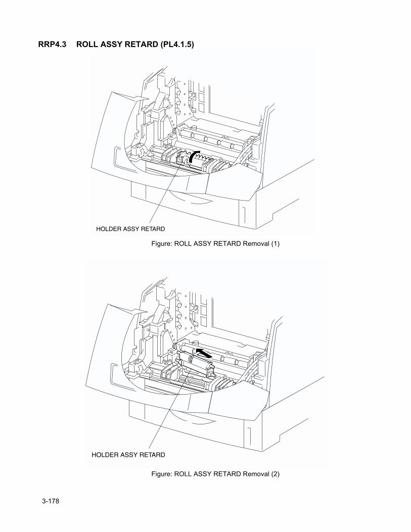
RRP4.3 ROLL ASSY RETARD (PL4.1.5)
Figure: ROLL ASSY RETARD Removal (1)
Figure: ROLL ASSY RETARD Removal (2)
3-178
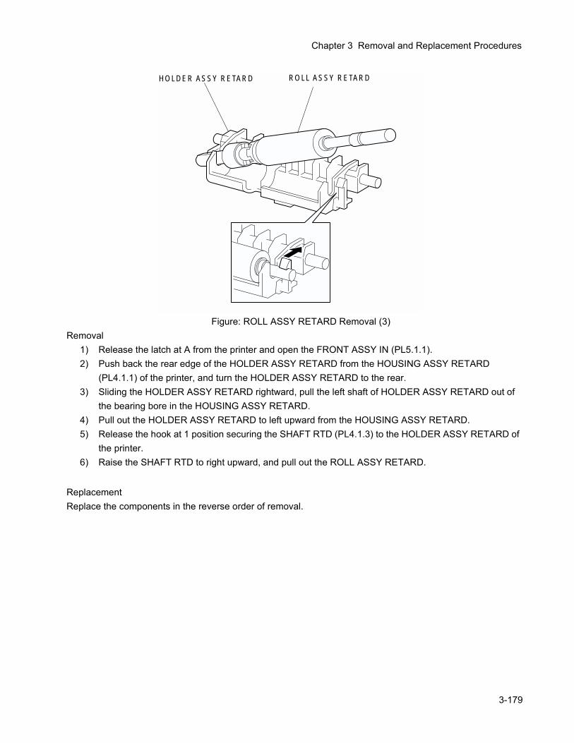
Chapter 3 Removal and Replacement Procedures
Figure: ROLL ASSY RETARD Removal (3)Removal
1) Release the latch at A from the printer and open the FRONT ASSY IN (PL5.1.1).2) Push back the rear edge of the HOLDER ASSY RETARD from the HOUSING ASSY RETARD
(PL4.1.1) of the printer, and turn the HOLDER ASSY RETARD to the rear.3) Sliding the HOLDER ASSY RETARD rightward, pull the left shaft of HOLDER ASSY RETARD out of
the bearing bore in the HOUSING ASSY RETARD.4) Pull out the HOLDER ASSY RETARD to left upward from the HOUSING ASSY RETARD.5) Release the hook at 1 position securing the SHAFT RTD (PL4.1.3) to the HOLDER ASSY RETARD of
the printer.6) Raise the SHAFT RTD to right upward, and pull out the ROLL ASSY RETARD.
ReplacementReplace the components in the reverse order of removal.
HOLDER ASSY RETARD ROLL ASSY RETARD
3-179
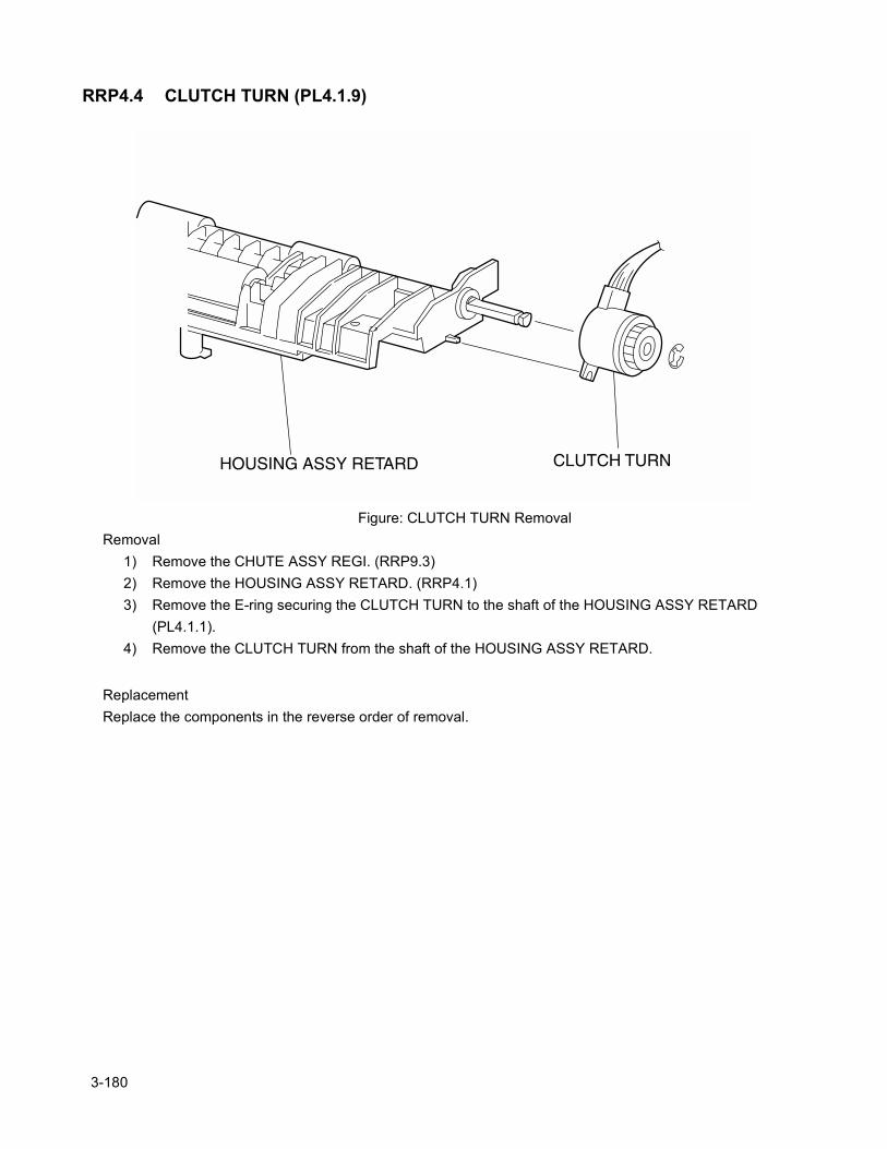
RRP4.4 CLUTCH TURN (PL4.1.9)
Figure: CLUTCH TURN RemovalRemoval
1) Remove the CHUTE ASSY REGI. (RRP9.3)2) Remove the HOUSING ASSY RETARD. (RRP4.1)3) Remove the E-ring securing the CLUTCH TURN to the shaft of the HOUSING ASSY RETARD
(PL4.1.1).4) Remove the CLUTCH TURN from the shaft of the HOUSING ASSY RETARD.
ReplacementReplace the components in the reverse order of removal.
3-180
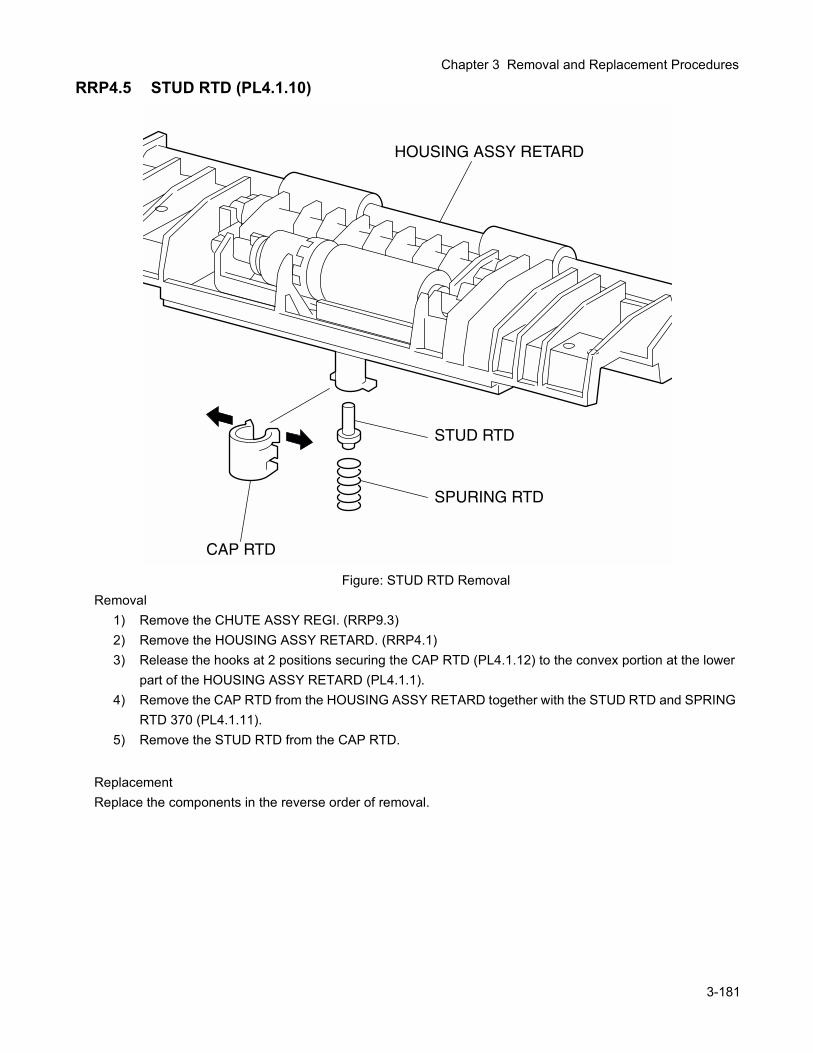
Chapter 3 Removal and Replacement Procedures
RRP4.5 STUD RTD (PL4.1.10)
Figure: STUD RTD RemovalRemoval
1) Remove the CHUTE ASSY REGI. (RRP9.3)2) Remove the HOUSING ASSY RETARD. (RRP4.1)3) Release the hooks at 2 positions securing the CAP RTD (PL4.1.12) to the convex portion at the lower
part of the HOUSING ASSY RETARD (PL4.1.1).4) Remove the CAP RTD from the HOUSING ASSY RETARD together with the STUD RTD and SPRING
RTD 370 (PL4.1.11).5) Remove the STUD RTD from the CAP RTD.
ReplacementReplace the components in the reverse order of removal.
3-181
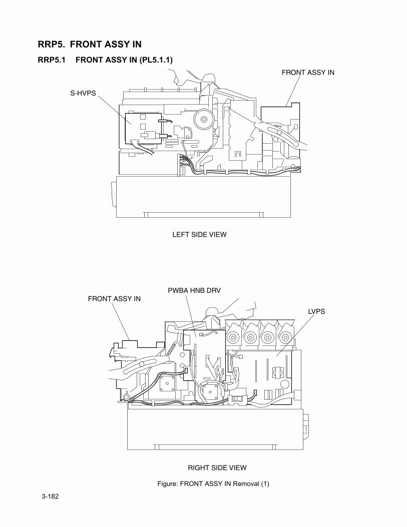
RRP5. FRONT ASSY INRRP5.1 FRONT ASSY IN (PL5.1.1)
Figure: FRONT ASSY IN Removal (1)
3-182
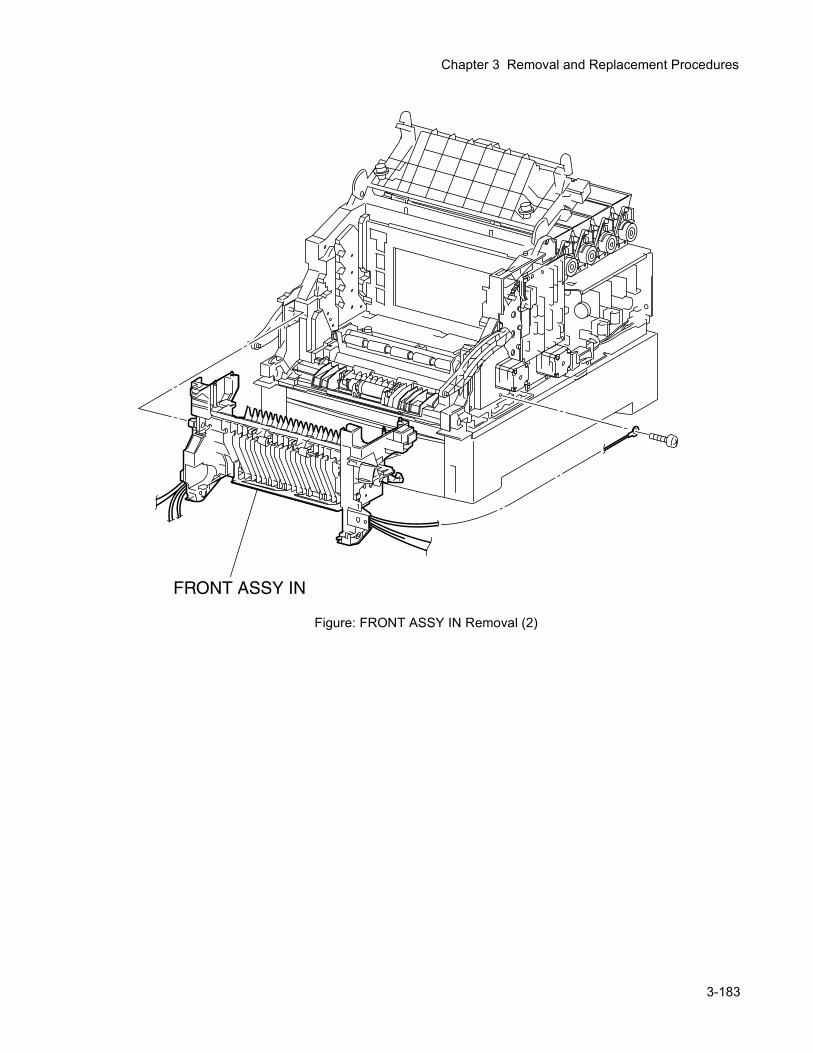
Chapter 3 Removal and Replacement Procedures
Figure: FRONT ASSY IN Removal (2)
3-183
Removal1) Remove the FUSER ASSY. (RRP8.1)2) Remove the BTR UNIT ASSY. (RRP8.4)3) Remove the COVER TOP MAIN. (RRP1.4)4) Remove the COVER ASSY FRONT HEAD. (RRP1.2)5) Remove the COVER MSI. (RRP1.11)6) Remove the TRAY ASSY MSI. (RRP1.12)7) Remove the COVER ASSY FRONT. (RRP1.13)8) Remove the COVER ASSY FRONT IN. (RRP1.10)9) Remove the COVER SIDE L. (RRP1.14)10) Remove the COVER SIDE R. (RRP1.9)11) Remove the CHUTE ASSY OUT. (RRP6.1)
In the following steps, lock the FRONT ASSY IN to the printer with the latch at A to prevent the FRONT ASSY IN from drop off.
12) Remove the connector (P/J5030) and connector (P/J5020) on the S-HVPS (PL10.1.17) from the left side of the printer.
13) Remove the connector (P/J141), connector (P/J1361), and connector (P/J138) from the connector bracket on the left side of the printer.
14) Shift the harness of the connectors removed above from the bottom portion of the HSG ASSY BIAS (PL9.1.4) on the left side of the printer.
15) Remove the connector (P/J52) on the PWBA HNB DRV (PL12.1.12) on the right side of the printer.16) Remove the connector (P/J162) on the LVPS STD (PL12.1.10) on the right side of the printer.17) Remove 1 screw securing the WIRE ASSY FSR EARTH (PL5.1.20) on the right side of the printer.18) Release the harness (P/J52) of the FUSER DRIVE ASSY (PL5.1.18) from the clamp on the MAIN
DRIVE ASSY (PL11.1.14).19) Shift the harness (P/J162) of the HARNESS ASSY FSR 2 (PL5.1.9) from the hook of the housing on
the right side of the printer.20) Release the latch at A from the printer, and pull out the FRONT ASSY IN frontward and remove.
ReplacementReplace the components in the reverse order of removal.
3-184
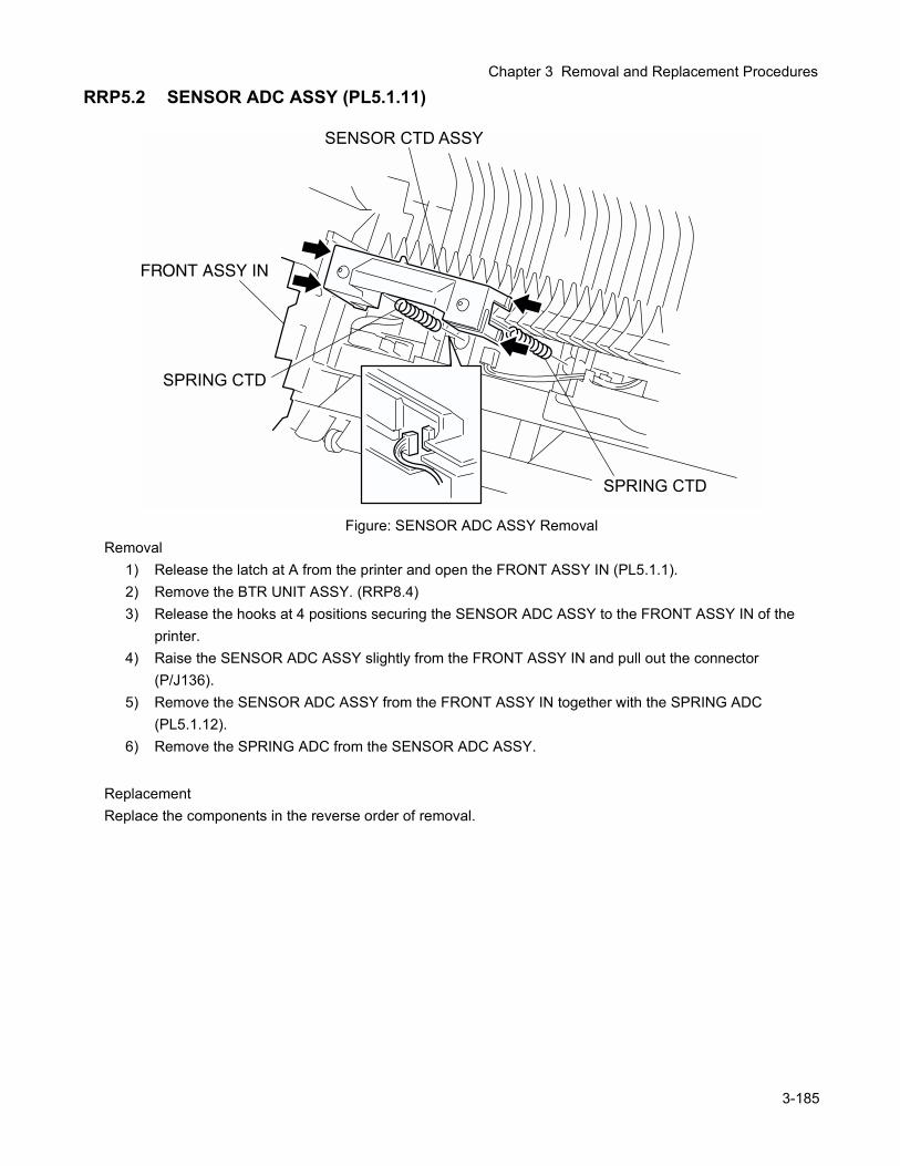
Chapter 3 Removal and Replacement Procedures
RRP5.2 SENSOR ADC ASSY (PL5.1.11)
Figure: SENSOR ADC ASSY RemovalRemoval
1) Release the latch at A from the printer and open the FRONT ASSY IN (PL5.1.1).2) Remove the BTR UNIT ASSY. (RRP8.4)3) Release the hooks at 4 positions securing the SENSOR ADC ASSY to the FRONT ASSY IN of the
printer.4) Raise the SENSOR ADC ASSY slightly from the FRONT ASSY IN and pull out the connector
(P/J136).5) Remove the SENSOR ADC ASSY from the FRONT ASSY IN together with the SPRING ADC
(PL5.1.12).6) Remove the SPRING ADC from the SENSOR ADC ASSY.
ReplacementReplace the components in the reverse order of removal.
3-185
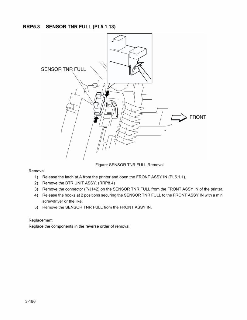
RRP5.3 SENSOR TNR FULL (PL5.1.13)
Figure: SENSOR TNR FULL RemovalRemoval
1) Release the latch at A from the printer and open the FRONT ASSY IN (PL5.1.1).2) Remove the BTR UNIT ASSY. (RRP8.4)3) Remove the connector (P/J142) on the SENSOR TNR FULL from the FRONT ASSY IN of the printer.4) Release the hooks at 2 positions securing the SENSOR TNR FULL to the FRONT ASSY IN with a mini
screwdriver or the like.5) Remove the SENSOR TNR FULL from the FRONT ASSY IN.
ReplacementReplace the components in the reverse order of removal.
3-186

Chapter 3 Removal and Replacement Procedures
3-187
Blank page.
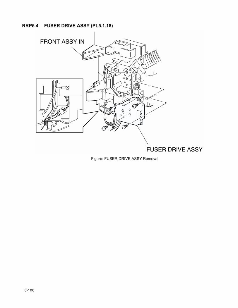
RRP5.4 FUSER DRIVE ASSY (PL5.1.18)
Figure: FUSER DRIVE ASSY Removal
3-188
Chapter 3 Removal and Replacement Procedures
Removal1) Remove the FUSER ASSY. (RRP8.1)2) Remove the BTR UNIT ASSY. (RRP8.4)3) Remove the COVER TOP MAIN. (RRP1.4)4) Remove the COVER ASSY FRONT HEAD. (RRP1.2)5) Remove the COVER MSI. (RRP1.11)6) Remove the TRAY ASSY MSI. (RRP1.12)7) Remove the COVER ASSY FRONT. (RRP1.13)8) Remove the CHUTE ASSY EXIT. (RRP7.1)9) Remove the COVER ASSY FRONT IN. (RRP1.10)10) Remove the COVER SIDE L. (RRP1.14)11) Remove the COVER SIDE R. (RRP1.9)12) Remove the CHUTE ASSY OUT. (RRP6.1)13) Remove the FRONT ASSY IN. (RRP5.1)14) Remove the LATCH R. (RRP5.5)15) Remove a screw securing the earth (P/J233) of the HARNESS ASSY FSR (PL4.1.9) to the FUSER
DRIVE ASSY of the FRONT ASSY IN (PL5.1.1).16) Remove a screw securing the edge (P/J235) of the WIRE ASSY FSR EARTH (PL5.1.20) to the MAIN
DRIVE ASSY (PL11.1.14).17) Shift the harness (P/J52) and earth (P/J235) of the FUSER DRIVE ASSY from the hook and housing,
secured to the FRONT ASSY IN (PL5.1.1).18) Remove 3 screws securing the FUSER DRIVE ASSY to the FRONT ASSY IN.19) Remove the FUSER DRIVE ASSY from the FRONT ASSY IN.
ReplacementReplace the components in the reverse order of removal.
3-189
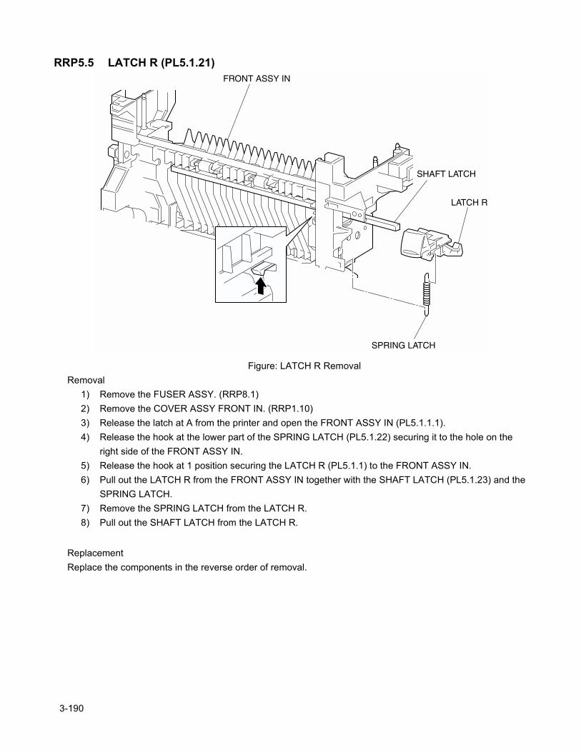
RRP5.5 LATCH R (PL5.1.21)
Figure: LATCH R RemovalRemoval
1) Remove the FUSER ASSY. (RRP8.1)2) Remove the COVER ASSY FRONT IN. (RRP1.10)3) Release the latch at A from the printer and open the FRONT ASSY IN (PL5.1.1.1).4) Release the hook at the lower part of the SPRING LATCH (PL5.1.22) securing it to the hole on the
right side of the FRONT ASSY IN.5) Release the hook at 1 position securing the LATCH R (PL5.1.1) to the FRONT ASSY IN.6) Pull out the LATCH R from the FRONT ASSY IN together with the SHAFT LATCH (PL5.1.23) and the
SPRING LATCH.7) Remove the SPRING LATCH from the LATCH R.8) Pull out the SHAFT LATCH from the LATCH R.
ReplacementReplace the components in the reverse order of removal.
3-190
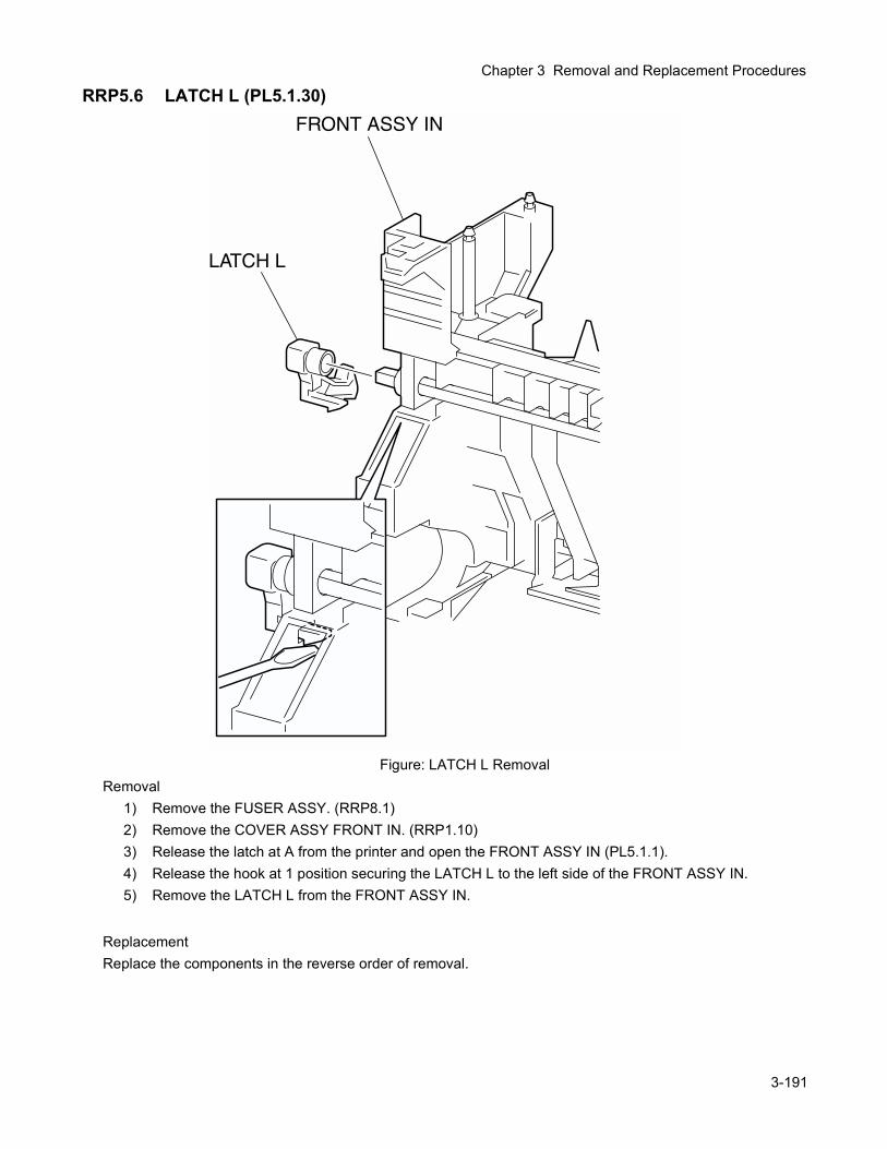
Chapter 3 Removal and Replacement Procedures
RRP5.6 LATCH L (PL5.1.30)
Figure: LATCH L RemovalRemoval
1) Remove the FUSER ASSY. (RRP8.1)2) Remove the COVER ASSY FRONT IN. (RRP1.10)3) Release the latch at A from the printer and open the FRONT ASSY IN (PL5.1.1).4) Release the hook at 1 position securing the LATCH L to the left side of the FRONT ASSY IN.5) Remove the LATCH L from the FRONT ASSY IN.
ReplacementReplace the components in the reverse order of removal.
3-191
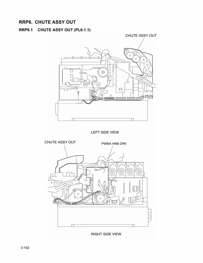
RRP6. CHUTE ASSY OUTRRP6.1 CHUTE ASSY OUT (PL6.1.1)
3-192
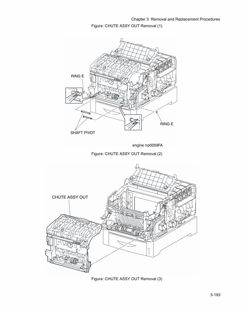
Chapter 3 Removal and Replacement Procedures
Figure: CHUTE ASSY OUT Removal (1)Figure: CHUTE ASSY OUT Removal (2)
Figure: CHUTE ASSY OUT Removal (3)
3-193
Removal1) Remove the FUSER ASSY. (RRP8.1)2) Remove the COVER TOP MAIN. (RRP1.4)3) Remove the COVER ASSY FRONT HEAD. (RRP1.2)4) Remove the COVER MSI. (RRP1.11)5) Remove the TRAY ASSY MSI. (RRP1.12)6) Remove the COVER ASSY FRONT. (RRP1.13)7) Remove the COVER ASSY FRONT IN. (RRP1.10)8) Remove the CHUTE ASSY EXIT. (RRP7.1)9) Remove the COVER SIDE L. (RRP1.14)10) Remove the COVER SIDE R. (RRP1.9)11) Remove the STRAP. (RRP8.6)
In the following step, lock the CHUTE ASSY OUT and FRONT ASSY IN (PL5.1.1) to the printer with the latches at A and B for drop off.
12) Remove the connector (P/J221) from the connector bracket on the left side surface of the printer.13) Remove the connector (P/J139) from the connector bracket on the left side surface of the printer.14) Shift the harness of the connector removed above from the bottom portion of the HSG ASSY BIAS
(PL9.1.4) on the left side surface of the printer.15) Remove the connector (P/J50) on the PWBA HNB DRV (PL12.1.12) on the right side surface of the
printer.16) Shift the harness (P/J50) of the HARNESS ASSY DUP (PL6.1.23) from the right side surface of the
printer.17) Remove the RING E (PL8.1.14) on the right and left SHAFT PIVOT (PL8.1.1) securing the bottom por-
tion of the CHUTE ASSY OUT from the printer.In the following steps, take care not to hurt your hand with burrs of the PLATE ASSY BOTTOM MSI (PL6.1.42).
18) Pull out the left SHAFT PIVOT from the CHUTE ASSY OUT inward with radio pliers.19) Pull out the right SHAFT PIVOT from the CHUTE ASSY OUT inward with radio pliers.20) Release the latch at B from the printer and pull out the CHUTE ASSY OUT frontward and remove.
ReplacementReplace the components in the reverse order of removal.
3-194
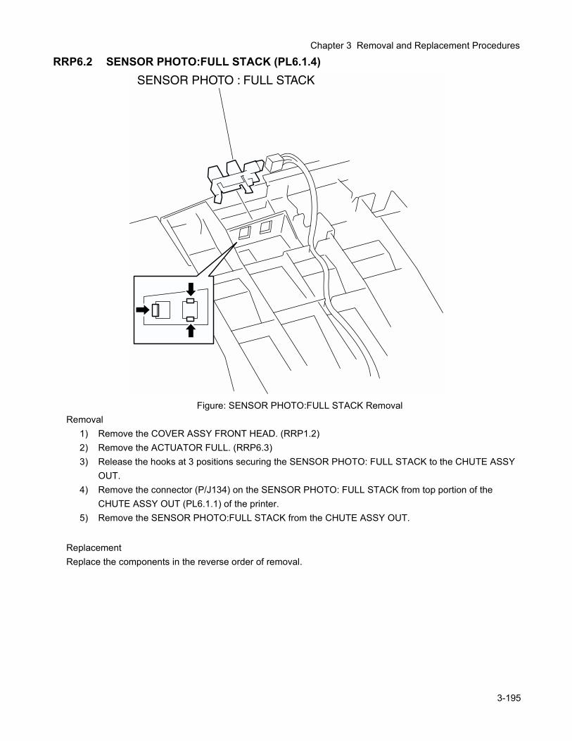
Chapter 3 Removal and Replacement Procedures
RRP6.2 SENSOR PHOTO:FULL STACK (PL6.1.4)
Figure: SENSOR PHOTO:FULL STACK RemovalRemoval
1) Remove the COVER ASSY FRONT HEAD. (RRP1.2)2) Remove the ACTUATOR FULL. (RRP6.3)3) Release the hooks at 3 positions securing the SENSOR PHOTO: FULL STACK to the CHUTE ASSY
OUT.4) Remove the connector (P/J134) on the SENSOR PHOTO: FULL STACK from top portion of the
CHUTE ASSY OUT (PL6.1.1) of the printer.5) Remove the SENSOR PHOTO:FULL STACK from the CHUTE ASSY OUT.
ReplacementReplace the components in the reverse order of removal.
3-195
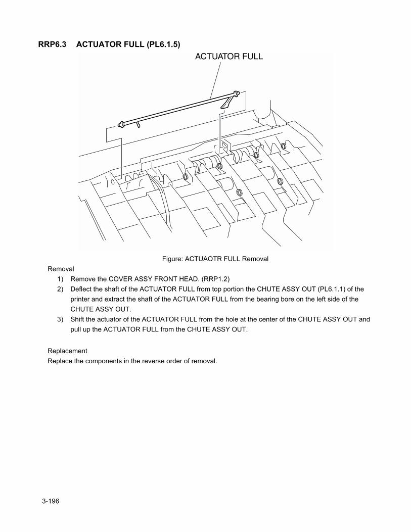
RRP6.3 ACTUATOR FULL (PL6.1.5)
Figure: ACTUAOTR FULL RemovalRemoval
1) Remove the COVER ASSY FRONT HEAD. (RRP1.2)2) Deflect the shaft of the ACTUATOR FULL from top portion the CHUTE ASSY OUT (PL6.1.1) of the
printer and extract the shaft of the ACTUATOR FULL from the bearing bore on the left side of the CHUTE ASSY OUT.
3) Shift the actuator of the ACTUATOR FULL from the hole at the center of the CHUTE ASSY OUT and pull up the ACTUATOR FULL from the CHUTE ASSY OUT.
ReplacementReplace the components in the reverse order of removal.
3-196
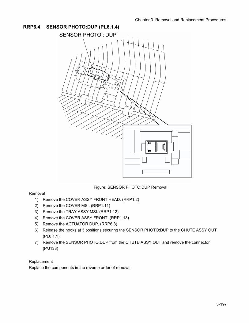
Chapter 3 Removal and Replacement Procedures
RRP6.4 SENSOR PHOTO:DUP (PL6.1.4)
Figure: SENSOR PHOTO:DUP RemovalRemoval
1) Remove the COVER ASSY FRONT HEAD. (RRP1.2)2) Remove the COVER MSI. (RRP1.11)3) Remove the TRAY ASSY MSI. (RRP1.12)4) Remove the COVER ASSY FRONT. (RRP1.13)5) Remove the ACTUATOR DUP. (RRP6.8)6) Release the hooks at 3 positions securing the SENSOR PHOTO:DUP to the CHUTE ASSY OUT
(PL6.1.1)7) Remove the SENSOR PHOTO:DUP from the CHUTE ASSY OUT and remove the connector
(P/J133)
ReplacementReplace the components in the reverse order of removal.
3-197
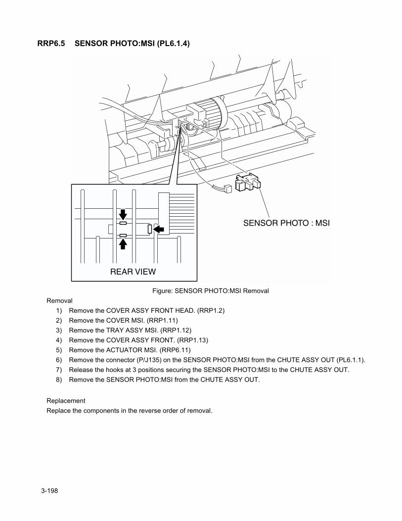
RRP6.5 SENSOR PHOTO:MSI (PL6.1.4)
Figure: SENSOR PHOTO:MSI RemovalRemoval
1) Remove the COVER ASSY FRONT HEAD. (RRP1.2)2) Remove the COVER MSI. (RRP1.11)3) Remove the TRAY ASSY MSI. (RRP1.12)4) Remove the COVER ASSY FRONT. (RRP1.13)5) Remove the ACTUATOR MSI. (RRP6.11)6) Remove the connector (P/J135) on the SENSOR PHOTO:MSI from the CHUTE ASSY OUT (PL6.1.1).7) Release the hooks at 3 positions securing the SENSOR PHOTO:MSI to the CHUTE ASSY OUT.8) Remove the SENSOR PHOTO:MSI from the CHUTE ASSY OUT.
ReplacementReplace the components in the reverse order of removal.
3-198
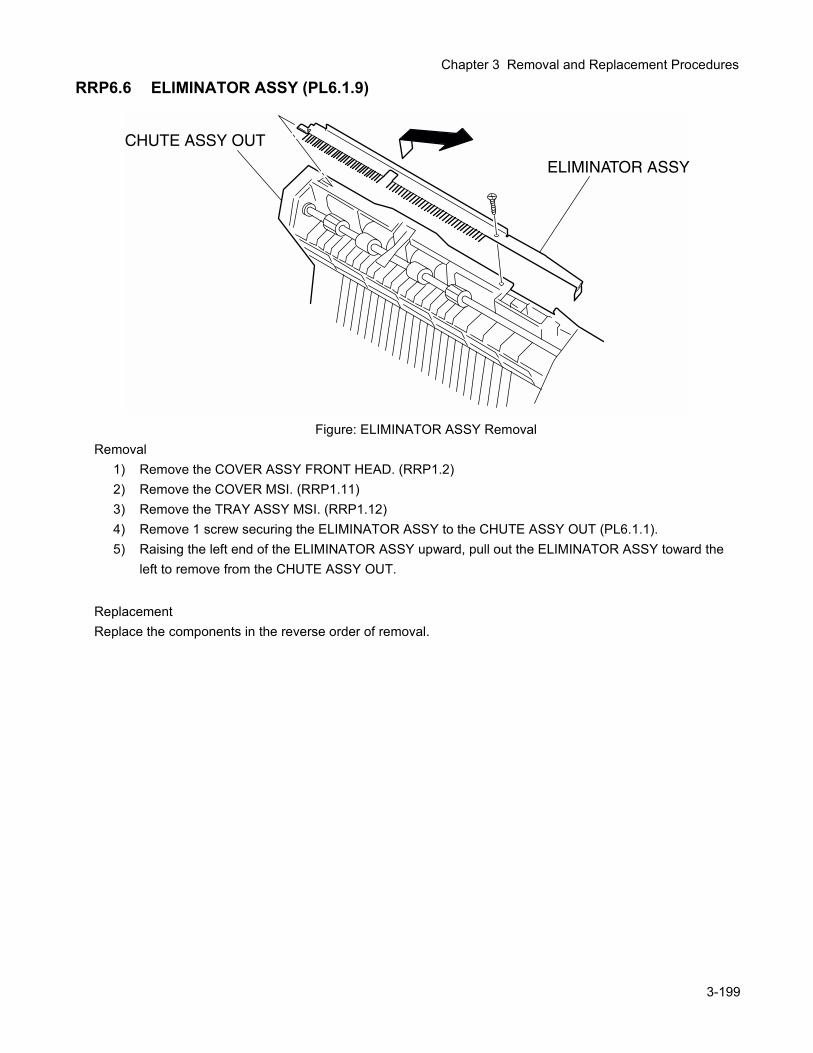
Chapter 3 Removal and Replacement Procedures
RRP6.6 ELIMINATOR ASSY (PL6.1.9)
Figure: ELIMINATOR ASSY RemovalRemoval
1) Remove the COVER ASSY FRONT HEAD. (RRP1.2)2) Remove the COVER MSI. (RRP1.11)3) Remove the TRAY ASSY MSI. (RRP1.12)4) Remove 1 screw securing the ELIMINATOR ASSY to the CHUTE ASSY OUT (PL6.1.1).5) Raising the left end of the ELIMINATOR ASSY upward, pull out the ELIMINATOR ASSY toward the
left to remove from the CHUTE ASSY OUT.
ReplacementReplace the components in the reverse order of removal.
3-199
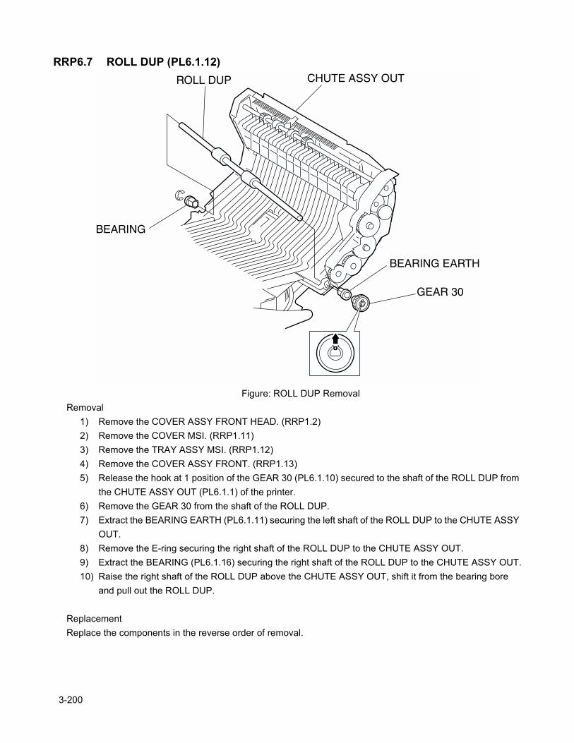
RRP6.7 ROLL DUP (PL6.1.12)
Figure: ROLL DUP RemovalRemoval
1) Remove the COVER ASSY FRONT HEAD. (RRP1.2)2) Remove the COVER MSI. (RRP1.11)3) Remove the TRAY ASSY MSI. (RRP1.12)4) Remove the COVER ASSY FRONT. (RRP1.13)5) Release the hook at 1 position of the GEAR 30 (PL6.1.10) secured to the shaft of the ROLL DUP from
the CHUTE ASSY OUT (PL6.1.1) of the printer.6) Remove the GEAR 30 from the shaft of the ROLL DUP.7) Extract the BEARING EARTH (PL6.1.11) securing the left shaft of the ROLL DUP to the CHUTE ASSY
OUT.8) Remove the E-ring securing the right shaft of the ROLL DUP to the CHUTE ASSY OUT.9) Extract the BEARING (PL6.1.16) securing the right shaft of the ROLL DUP to the CHUTE ASSY OUT.10) Raise the right shaft of the ROLL DUP above the CHUTE ASSY OUT, shift it from the bearing bore
and pull out the ROLL DUP.
ReplacementReplace the components in the reverse order of removal.
3-200

Chapter 3 Removal and Replacement Procedures
3-201
Blank page.
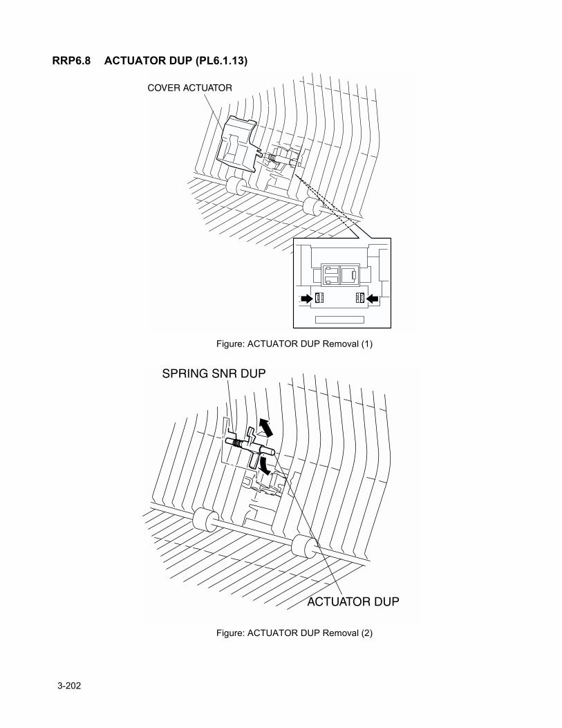
RRP6.8 ACTUATOR DUP (PL6.1.13)
Figure: ACTUATOR DUP Removal (1)
Figure: ACTUATOR DUP Removal (2)
3-202

Chapter 3 Removal and Replacement Procedures
Removal1) Remove the COVER ASSY FRONT HEAD. (RRP1.2)2) Remove the COVER MSI. (RRP1.11)3) Remove the TRAY ASSY MSI. (RRP1.12)4) Remove the COVER ASSY FRONT. (RRP1.13)5) Release the hooks at 2 positions securing the COVER ACTUATOR (PL6.1.14) to the CHUTE ASSY
OUT (PL6.1.1) of the printer.6) Remove the COVER ACTUATOR from the CHUTE ASSY OUT.7) Pushing the actuator of the ACTUATOR DUP inward from the CHUTE ASSY OUT, slide the ACTUA-
TOR DUP leftward and extract the right side shaft of the ACTUATOR DUP from the right side bearing.8) Extract the ACTUATOR DUP from the CHUTE ASSY OUT together with the SPRING SNR DUP.9) Remove the SPRING SNR DUP (PL6.1.15) from the ACTUATOR DUP.
ReplacementReplace the components in the reverse order of removal.
3-203
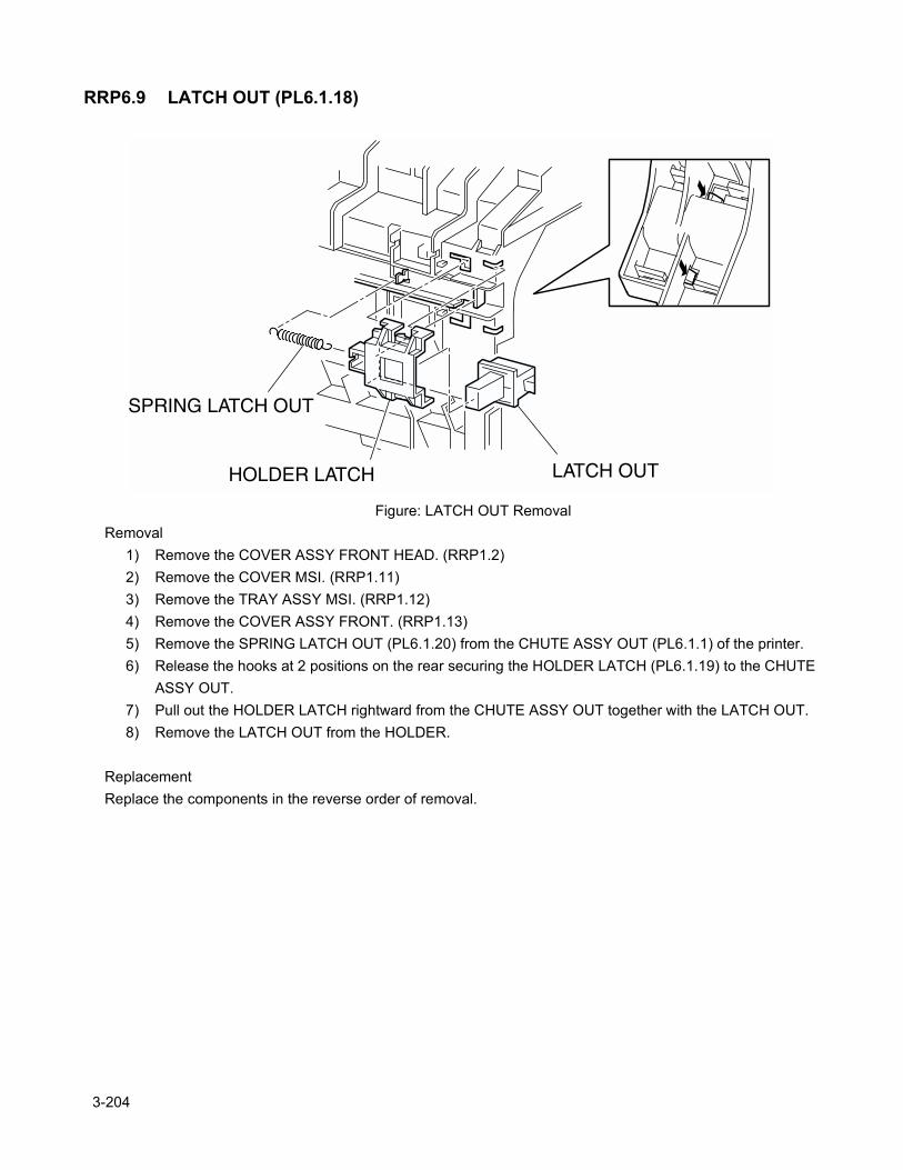
RRP6.9 LATCH OUT (PL6.1.18)
Figure: LATCH OUT RemovalRemoval
1) Remove the COVER ASSY FRONT HEAD. (RRP1.2)2) Remove the COVER MSI. (RRP1.11)3) Remove the TRAY ASSY MSI. (RRP1.12)4) Remove the COVER ASSY FRONT. (RRP1.13)5) Remove the SPRING LATCH OUT (PL6.1.20) from the CHUTE ASSY OUT (PL6.1.1) of the printer.6) Release the hooks at 2 positions on the rear securing the HOLDER LATCH (PL6.1.19) to the CHUTE
ASSY OUT.7) Pull out the HOLDER LATCH rightward from the CHUTE ASSY OUT together with the LATCH OUT.8) Remove the LATCH OUT from the HOLDER.
ReplacementReplace the components in the reverse order of removal.
3-204
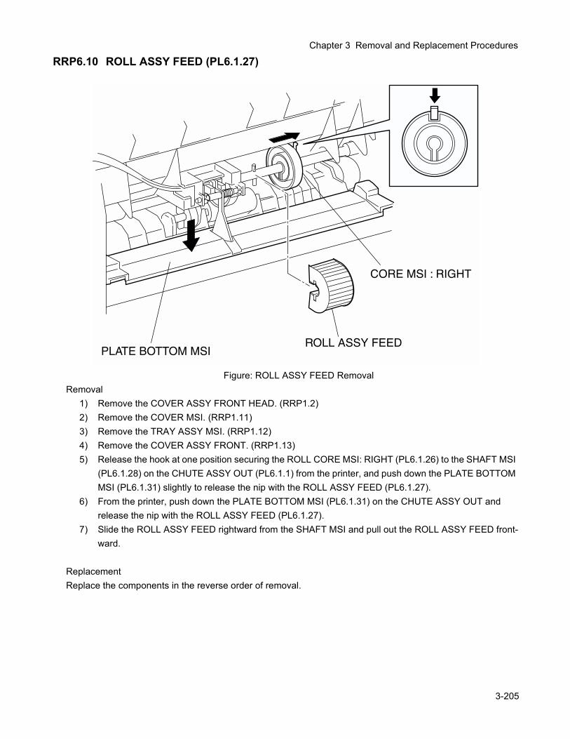
Chapter 3 Removal and Replacement Procedures
RRP6.10 ROLL ASSY FEED (PL6.1.27)
Figure: ROLL ASSY FEED RemovalRemoval
1) Remove the COVER ASSY FRONT HEAD. (RRP1.2)2) Remove the COVER MSI. (RRP1.11)3) Remove the TRAY ASSY MSI. (RRP1.12)4) Remove the COVER ASSY FRONT. (RRP1.13)5) Release the hook at one position securing the ROLL CORE MSI: RIGHT (PL6.1.26) to the SHAFT MSI
(PL6.1.28) on the CHUTE ASSY OUT (PL6.1.1) from the printer, and push down the PLATE BOTTOM MSI (PL6.1.31) slightly to release the nip with the ROLL ASSY FEED (PL6.1.27).
6) From the printer, push down the PLATE BOTTOM MSI (PL6.1.31) on the CHUTE ASSY OUT and release the nip with the ROLL ASSY FEED (PL6.1.27).
7) Slide the ROLL ASSY FEED rightward from the SHAFT MSI and pull out the ROLL ASSY FEED front-ward.
ReplacementReplace the components in the reverse order of removal.
3-205
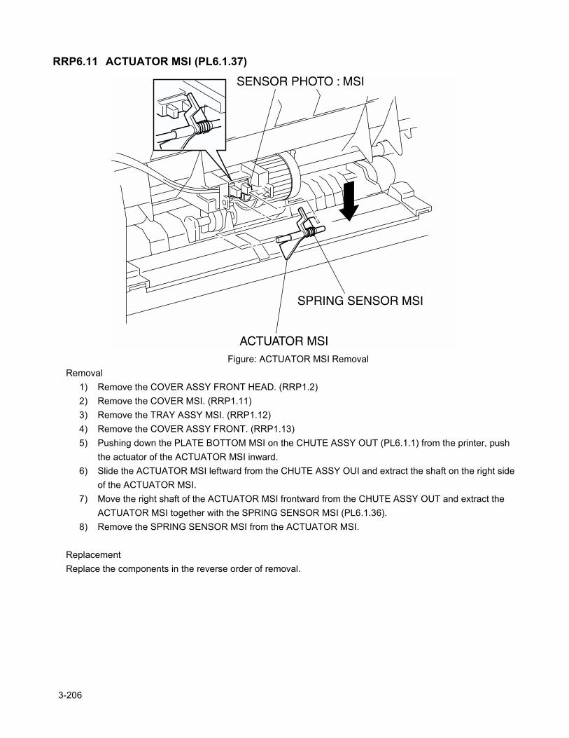
RRP6.11 ACTUATOR MSI (PL6.1.37)
Figure: ACTUATOR MSI RemovalRemoval
1) Remove the COVER ASSY FRONT HEAD. (RRP1.2)2) Remove the COVER MSI. (RRP1.11)3) Remove the TRAY ASSY MSI. (RRP1.12)4) Remove the COVER ASSY FRONT. (RRP1.13)5) Pushing down the PLATE BOTTOM MSI on the CHUTE ASSY OUT (PL6.1.1) from the printer, push
the actuator of the ACTUATOR MSI inward.6) Slide the ACTUATOR MSI leftward from the CHUTE ASSY OUI and extract the shaft on the right side
of the ACTUATOR MSI.7) Move the right shaft of the ACTUATOR MSI frontward from the CHUTE ASSY OUT and extract the
ACTUATOR MSI together with the SPRING SENSOR MSI (PL6.1.36).8) Remove the SPRING SENSOR MSI from the ACTUATOR MSI.
ReplacementReplace the components in the reverse order of removal.
3-206
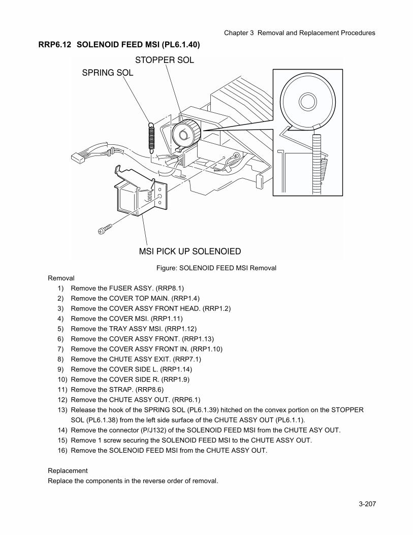
Chapter 3 Removal and Replacement Procedures
RRP6.12 SOLENOID FEED MSI (PL6.1.40)
Figure: SOLENOID FEED MSI RemovalRemoval
1) Remove the FUSER ASSY. (RRP8.1)2) Remove the COVER TOP MAIN. (RRP1.4)3) Remove the COVER ASSY FRONT HEAD. (RRP1.2)4) Remove the COVER MSI. (RRP1.11)5) Remove the TRAY ASSY MSI. (RRP1.12)6) Remove the COVER ASSY FRONT. (RRP1.13)7) Remove the COVER ASSY FRONT IN. (RRP1.10)8) Remove the CHUTE ASSY EXIT. (RRP7.1)9) Remove the COVER SIDE L. (RRP1.14)10) Remove the COVER SIDE R. (RRP1.9)11) Remove the STRAP. (RRP8.6)12) Remove the CHUTE ASSY OUT. (RRP6.1)13) Release the hook of the SPRING SOL (PL6.1.39) hitched on the convex portion on the STOPPER
SOL (PL6.1.38) from the left side surface of the CHUTE ASSY OUT (PL6.1.1).14) Remove the connector (P/J132) of the SOLENOID FEED MSI from the CHUTE ASY OUT.15) Remove 1 screw securing the SOLENOID FEED MSI to the CHUTE ASSY OUT.16) Remove the SOLENOID FEED MSI from the CHUTE ASSY OUT.
ReplacementReplace the components in the reverse order of removal.
3-207
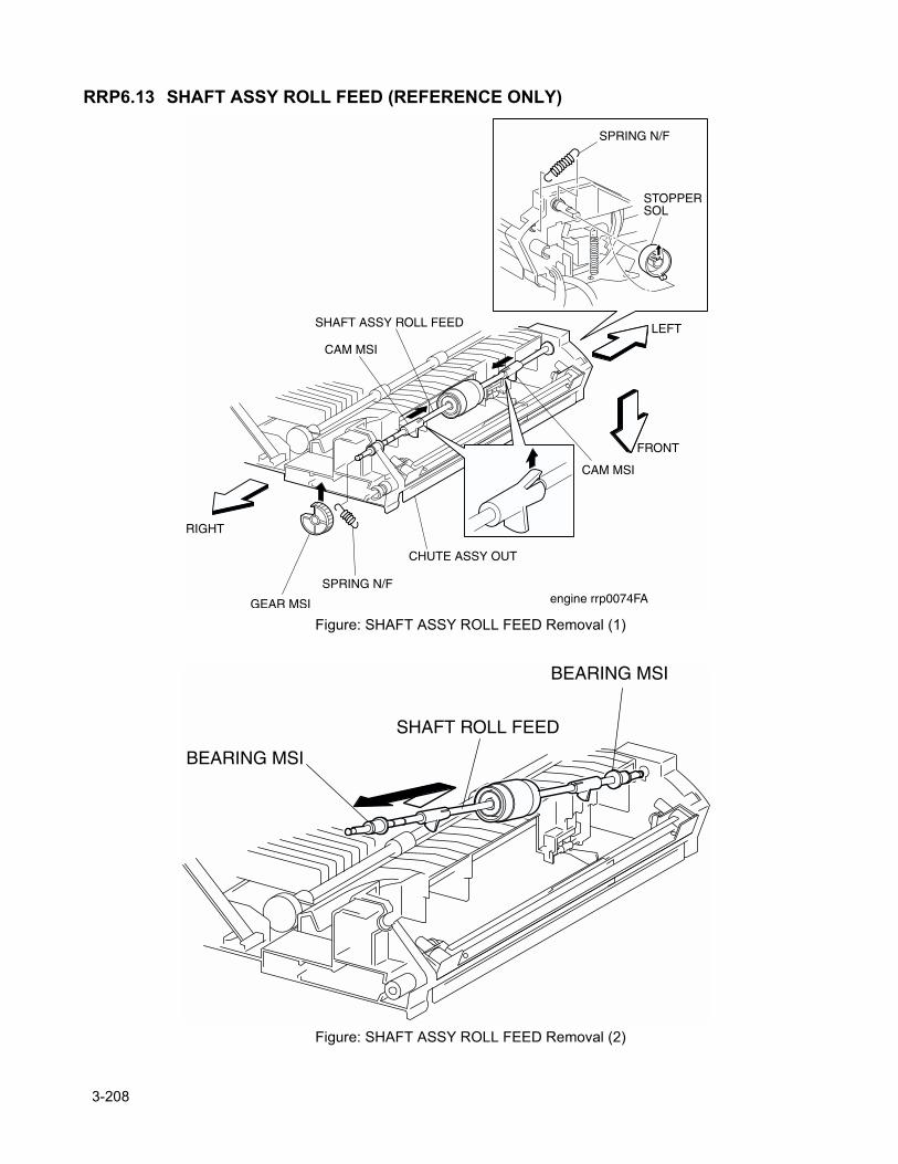
RRP6.13 SHAFT ASSY ROLL FEED (REFERENCE ONLY)
Figure: SHAFT ASSY ROLL FEED Removal (1)
Figure: SHAFT ASSY ROLL FEED Removal (2)
3-208
Chapter 3 Removal and Replacement Procedures
Removal1) Remove the FUSER ASSY. (RRP8.1)2) Remove the COVER TOP MAIN. (RRP1.4)3) Remove the COVER ASSY FRONT HEAD. (RRP1.2)4) Remove the COVER MSI. (RRP1.11)5) Remove the TRAY ASSY MSI. (RRP1.12)6) Remove the COVER ASSY FRONT. (RRP1.13)7) Remove the COVER ASSY FRONT IN. (RRP1.10)8) Remove the CHUTE ASSY EXIT. (RRP7.1)9) Remove the COVER SIDE L. (RRP1.14)10) Remove the COVER SIDE R. (RRP1.9)11) Remove the STRAP. (RRP8.6)12) Remove the CHUTE ASSY OUT. (RRP6.1)13) Remove the SOLENOID FEED MSI. (RRP6.2)14) Release a hook of the SPRING SOL (PL6.1.39) from a convex portion on the STOPPER SOL
(PL6.1.38) from the CHUTE ASSY OUT.15) Release the hook at 1 position securing the STOPPER SOL to the left shaft of SHAFT MSI, and pull
out the STOPPER SOL of the shaft from the CHUTE ASSY OUT.16) Release the hook at 1 position securing the GEAR MSI (PL6.1.22) to the right shaft of SHAFT MSI,
and pull the GEAR MSI out of the shaft from the CHUTE ASSY OUT.17) Release the hooks of the SPRING N/F (PL6.1.21) from the left and right shafts of SHAFT ASSY ROLL
FEED from the CHUTE ASSY OUT.18) Release the hook at 1 position securing the CAM MSI (PL6.1.25) to the SHAFT MSI (PL6.1.28), and
move the CAM MSI inside from the CHUTE ASSY OUT (PL6.1.1).19) Pull off the BEARING MSI (PL6.1.24) on the SHAFT MSI toward the inside from the bearing of the
CHUTE ASSY OUT.20) Raising the right end of the SHAFT ASSY ROLL FEED, pull out the SHAFT ASSY FEED from the
CHUTE ASSY OUT.21) After removing the SHAFT ASSY FEED, be sure to replace the CAM MSI. Do not leave the hook of the
CAM MSI being raised.
ReplacementReplace the components in the reverse order of removal.
3-209
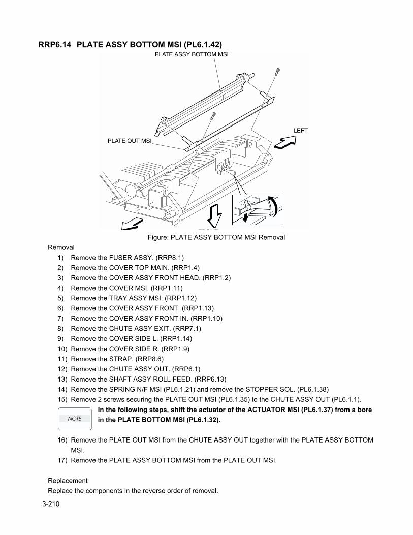
RRP6.14 PLATE ASSY BOTTOM MSI (PL6.1.42)
Figure: PLATE ASSY BOTTOM MSI RemovalRemoval
1) Remove the FUSER ASSY. (RRP8.1)2) Remove the COVER TOP MAIN. (RRP1.4)3) Remove the COVER ASSY FRONT HEAD. (RRP1.2)4) Remove the COVER MSI. (RRP1.11)5) Remove the TRAY ASSY MSI. (RRP1.12)6) Remove the COVER ASSY FRONT. (RRP1.13)7) Remove the COVER ASSY FRONT IN. (RRP1.10)8) Remove the CHUTE ASSY EXIT. (RRP7.1)9) Remove the COVER SIDE L. (RRP1.14)10) Remove the COVER SIDE R. (RRP1.9)11) Remove the STRAP. (RRP8.6)12) Remove the CHUTE ASSY OUT. (RRP6.1)13) Remove the SHAFT ASSY ROLL FEED. (RRP6.13)14) Remove the SPRING N/F MSI (PL6.1.21) and remove the STOPPER SOL. (PL6.1.38)15) Remove 2 screws securing the PLATE OUT MSI (PL6.1.35) to the CHUTE ASSY OUT (PL6.1.1).
In the following steps, shift the actuator of the ACTUATOR MSI (PL6.1.37) from a bore in the PLATE BOTTOM MSI (PL6.1.32).
16) Remove the PLATE OUT MSI from the CHUTE ASSY OUT together with the PLATE ASSY BOTTOM MSI.
17) Remove the PLATE ASSY BOTTOM MSI from the PLATE OUT MSI.
ReplacementReplace the components in the reverse order of removal.
3-210
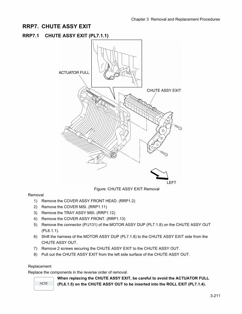
Chapter 3 Removal and Replacement Procedures
RRP7. CHUTE ASSY EXITRRP7.1 CHUTE ASSY EXIT (PL7.1.1)
Figure: CHUTE ASSY EXIT RemovalRemoval
1) Remove the COVER ASSY FRONT HEAD. (RRP1.2)2) Remove the COVER MSI. (RRP1.11)3) Remove the TRAY ASSY MSI. (RRP1.12)4) Remove the COVER ASSY FRONT. (RRP1.13)5) Remove the connector (P/J131) of the MOTOR ASSY DUP (PL7.1.8) on the CHUTE ASSY OUT
(PL6.1.1).6) Shift the harness of the MOTOR ASSY DUP (PL7.1.8) to the CHUTE ASSY EXIT side from the
CHUTE ASSY OUT.7) Remove 2 screws securing the CHUTE ASSY EXIT to the CHUTE ASSY OUT.8) Pull out the CHUTE ASSY EXIT from the left side surface of the CHUTE ASSY OUT.
ReplacementReplace the components in the reverse order of removal.
When replacing the CHUTE ASSY EXIT, be careful to avoid the ACTUATOR FULL (PL6.1.5) on the CHUTE ASSY OUT to be inserted into the ROLL EXIT (PL7.1.4).
3-211
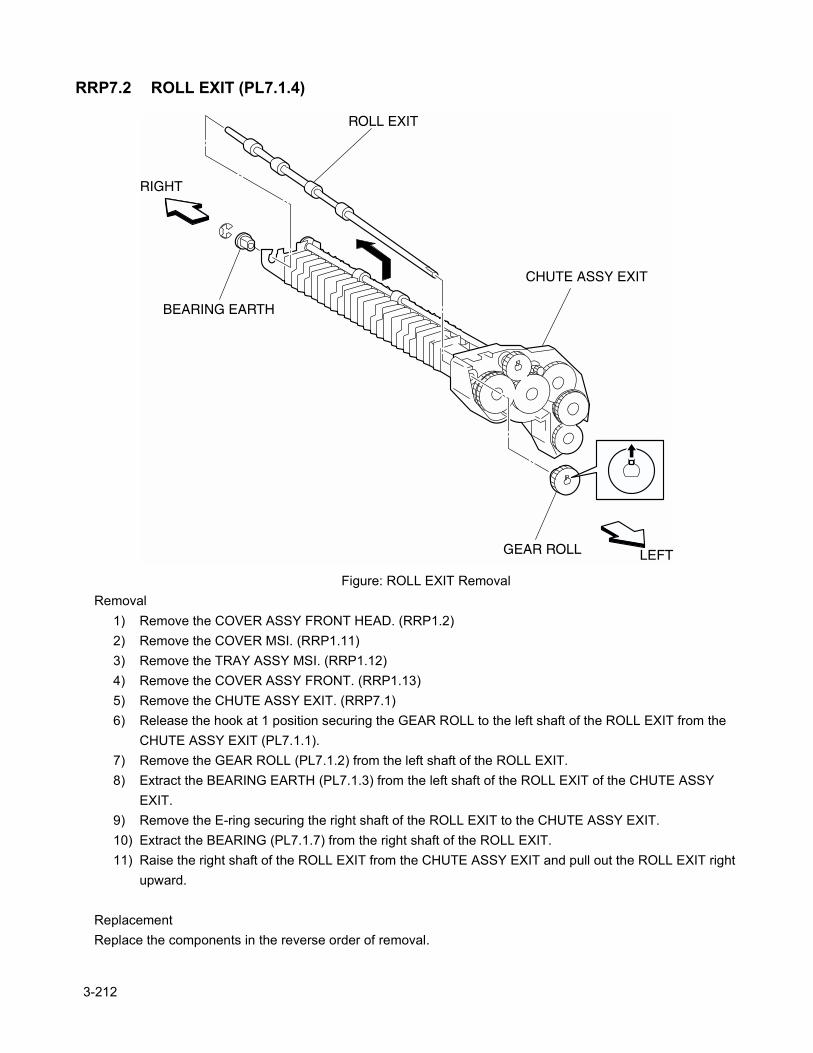
RRP7.2 ROLL EXIT (PL7.1.4)
Figure: ROLL EXIT RemovalRemoval
1) Remove the COVER ASSY FRONT HEAD. (RRP1.2)2) Remove the COVER MSI. (RRP1.11)3) Remove the TRAY ASSY MSI. (RRP1.12)4) Remove the COVER ASSY FRONT. (RRP1.13)5) Remove the CHUTE ASSY EXIT. (RRP7.1)6) Release the hook at 1 position securing the GEAR ROLL to the left shaft of the ROLL EXIT from the
CHUTE ASSY EXIT (PL7.1.1).7) Remove the GEAR ROLL (PL7.1.2) from the left shaft of the ROLL EXIT.8) Extract the BEARING EARTH (PL7.1.3) from the left shaft of the ROLL EXIT of the CHUTE ASSY
EXIT.9) Remove the E-ring securing the right shaft of the ROLL EXIT to the CHUTE ASSY EXIT.10) Extract the BEARING (PL7.1.7) from the right shaft of the ROLL EXIT.11) Raise the right shaft of the ROLL EXIT from the CHUTE ASSY EXIT and pull out the ROLL EXIT right
upward.
ReplacementReplace the components in the reverse order of removal.
3-212
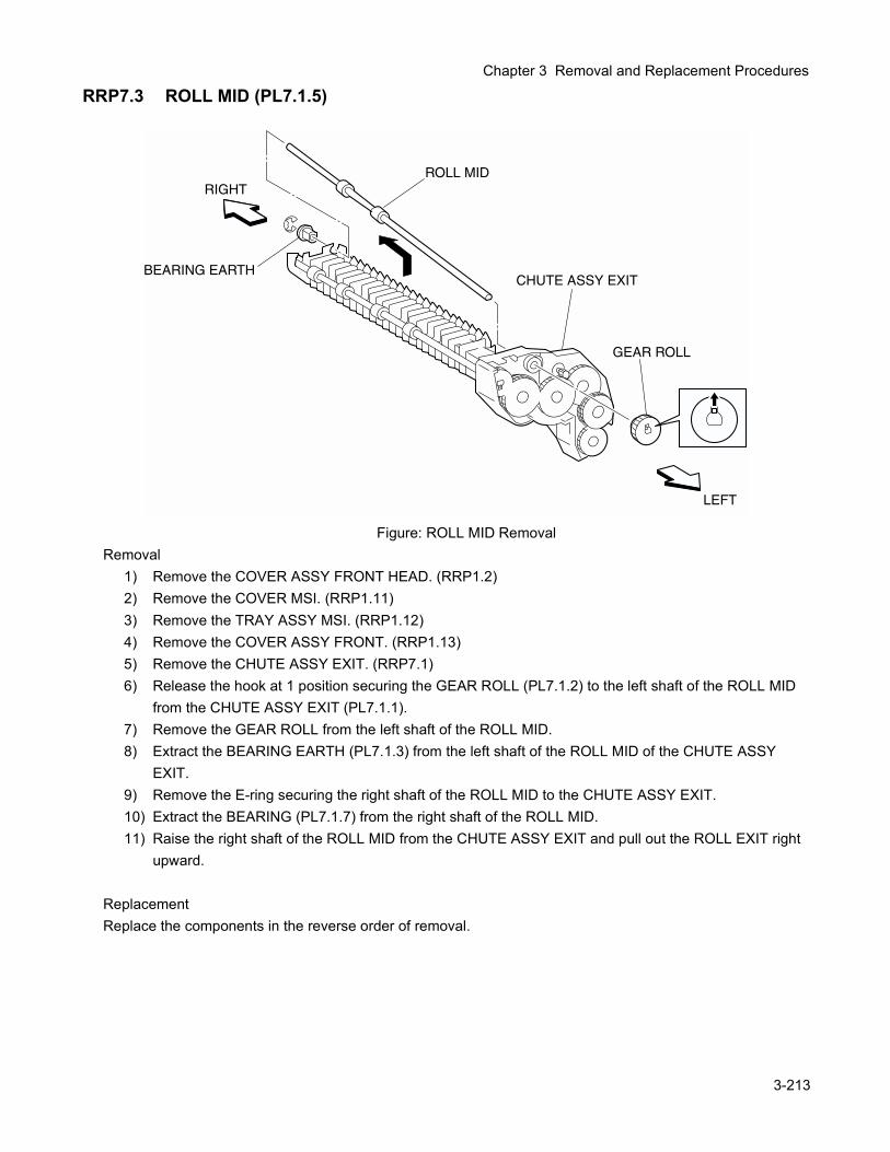
Chapter 3 Removal and Replacement Procedures
RRP7.3 ROLL MID (PL7.1.5)
Figure: ROLL MID RemovalRemoval
1) Remove the COVER ASSY FRONT HEAD. (RRP1.2)2) Remove the COVER MSI. (RRP1.11)3) Remove the TRAY ASSY MSI. (RRP1.12)4) Remove the COVER ASSY FRONT. (RRP1.13)5) Remove the CHUTE ASSY EXIT. (RRP7.1)6) Release the hook at 1 position securing the GEAR ROLL (PL7.1.2) to the left shaft of the ROLL MID
from the CHUTE ASSY EXIT (PL7.1.1).7) Remove the GEAR ROLL from the left shaft of the ROLL MID.8) Extract the BEARING EARTH (PL7.1.3) from the left shaft of the ROLL MID of the CHUTE ASSY
EXIT.9) Remove the E-ring securing the right shaft of the ROLL MID to the CHUTE ASSY EXIT.10) Extract the BEARING (PL7.1.7) from the right shaft of the ROLL MID.11) Raise the right shaft of the ROLL MID from the CHUTE ASSY EXIT and pull out the ROLL EXIT right
upward.
ReplacementReplace the components in the reverse order of removal.
3-213
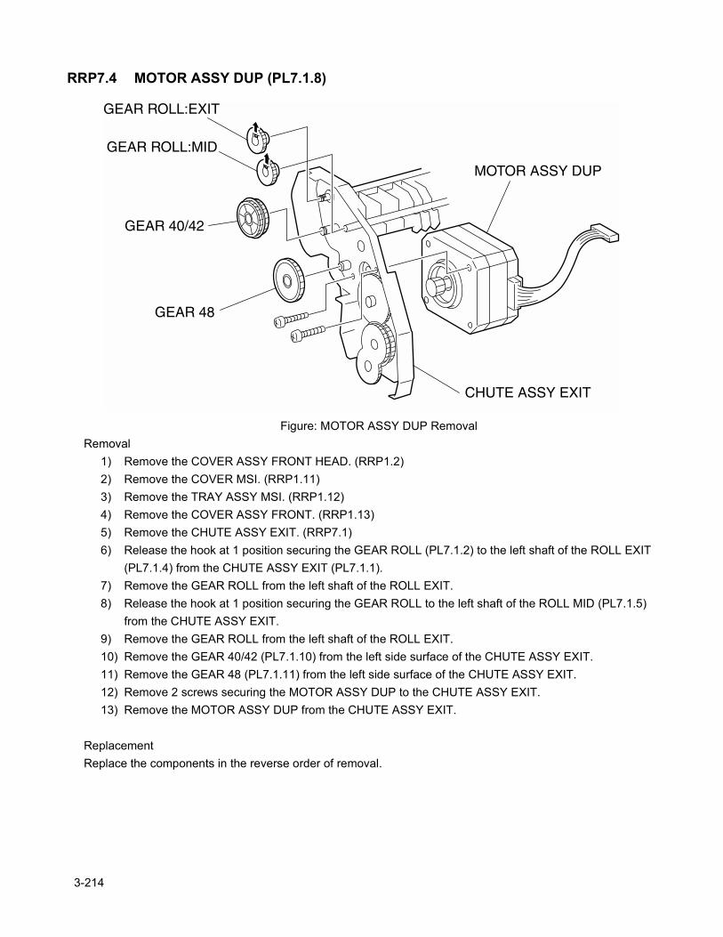
RRP7.4 MOTOR ASSY DUP (PL7.1.8)
Figure: MOTOR ASSY DUP RemovalRemoval
1) Remove the COVER ASSY FRONT HEAD. (RRP1.2)2) Remove the COVER MSI. (RRP1.11)3) Remove the TRAY ASSY MSI. (RRP1.12)4) Remove the COVER ASSY FRONT. (RRP1.13)5) Remove the CHUTE ASSY EXIT. (RRP7.1)6) Release the hook at 1 position securing the GEAR ROLL (PL7.1.2) to the left shaft of the ROLL EXIT
(PL7.1.4) from the CHUTE ASSY EXIT (PL7.1.1).7) Remove the GEAR ROLL from the left shaft of the ROLL EXIT.8) Release the hook at 1 position securing the GEAR ROLL to the left shaft of the ROLL MID (PL7.1.5)
from the CHUTE ASSY EXIT.9) Remove the GEAR ROLL from the left shaft of the ROLL EXIT.10) Remove the GEAR 40/42 (PL7.1.10) from the left side surface of the CHUTE ASSY EXIT.11) Remove the GEAR 48 (PL7.1.11) from the left side surface of the CHUTE ASSY EXIT.12) Remove 2 screws securing the MOTOR ASSY DUP to the CHUTE ASSY EXIT.13) Remove the MOTOR ASSY DUP from the CHUTE ASSY EXIT.
ReplacementReplace the components in the reverse order of removal.
3-214
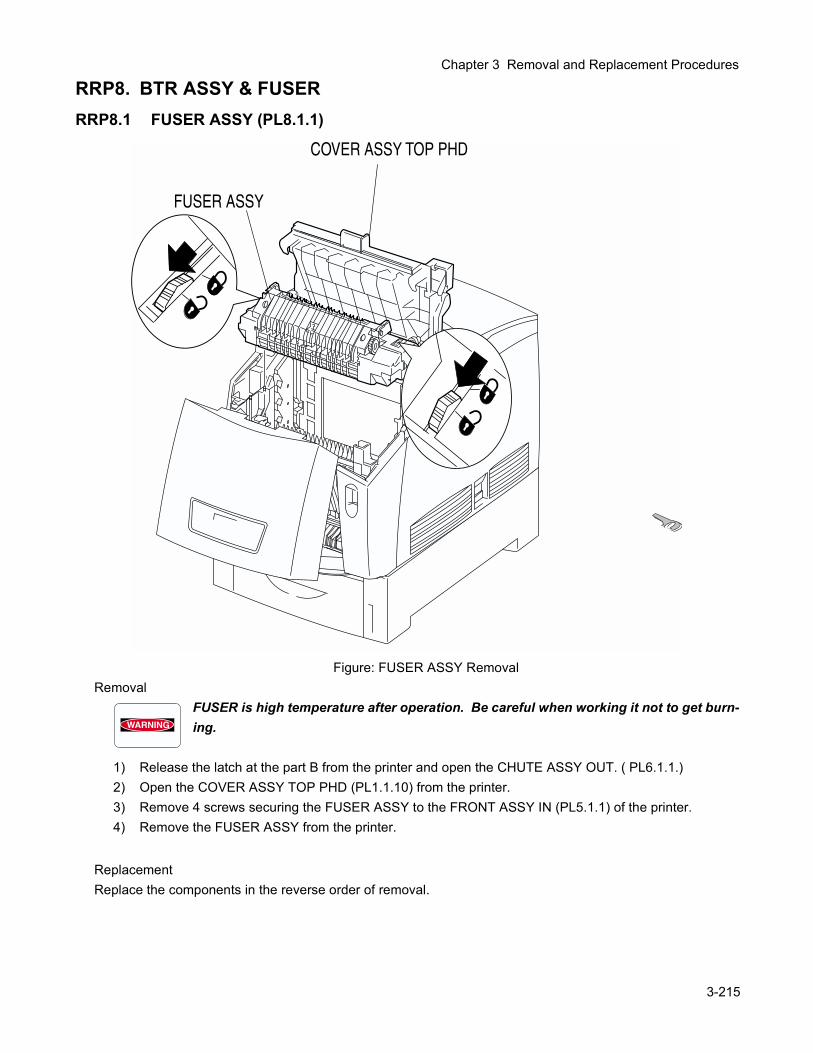
Chapter 3 Removal and Replacement Procedures
RRP8. BTR ASSY & FUSERRRP8.1 FUSER ASSY (PL8.1.1)
Figure: FUSER ASSY RemovalRemoval
FUSER is high temperature after operation. Be careful when working it not to get burn-ing.
1) Release the latch at the part B from the printer and open the CHUTE ASSY OUT. ( PL6.1.1.)2) Open the COVER ASSY TOP PHD (PL1.1.10) from the printer.3) Remove 4 screws securing the FUSER ASSY to the FRONT ASSY IN (PL5.1.1) of the printer.4) Remove the FUSER ASSY from the printer.
ReplacementReplace the components in the reverse order of removal.
3-215
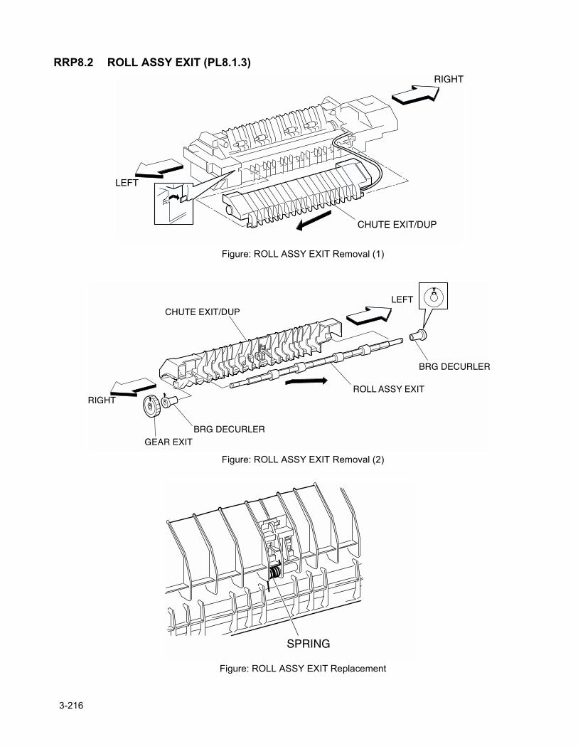
RRP8.2 ROLL ASSY EXIT (PL8.1.3)
Figure: ROLL ASSY EXIT Removal (1)
Figure: ROLL ASSY EXIT Removal (2)
Figure: ROLL ASSY EXIT Replacement
3-216
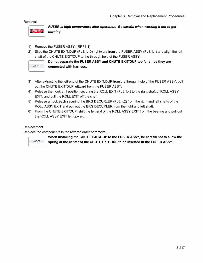
Chapter 3 Removal and Replacement Procedures
RemovalFUSER is high temperature after operation. Be careful when working it not to get burning.
1) Remove the FUSER ASSY. (RRP8.1)2) Slide the CHUTE EXIT/DUP (PL8.1.10) rightward from the FUSER ASSY (PL8.1.1) and align the left
shaft of the CHUTE EXIT/DUP to the through hole of the FUSER ASSY.Do not separate the FUSER ASSY and CHUTE EXIT/DUP too far since they are connected with harness.
3) After extracting the left end of the CHUTE EXIT/DUP from the through hole of the FUSER ASSY, pull out the CHUTE EXIT/DUP leftward from the FUSER ASSY.
4) Release the hook at 1 position securing the ROLL EXIT (PL8.1.4) to the right shaft of ROLL ASSY EXIT, and pull the ROLL EXIT off the shaft.
5) Release a hook each securing the BRG DECURLER (PL8.1.2) from the right and left shafts of the ROLL ASSY EXIT and pull out the BRG DECURLER from the right and left shaft.
6) From the CHUTE EXIT/DUP, shift the left end of the ROLL ASSY EXIT from the bearing and pull out the ROLL ASSY EXIT left upward.
ReplacementReplace the components in the reverse order of removal.
When installing the CHUTE EXIT/DUP to the FUSER ASSY, be careful not to allow the spring at the center of the CHUTE EXIT/DUP to be inserted in the FUSER ASSY.
3-217
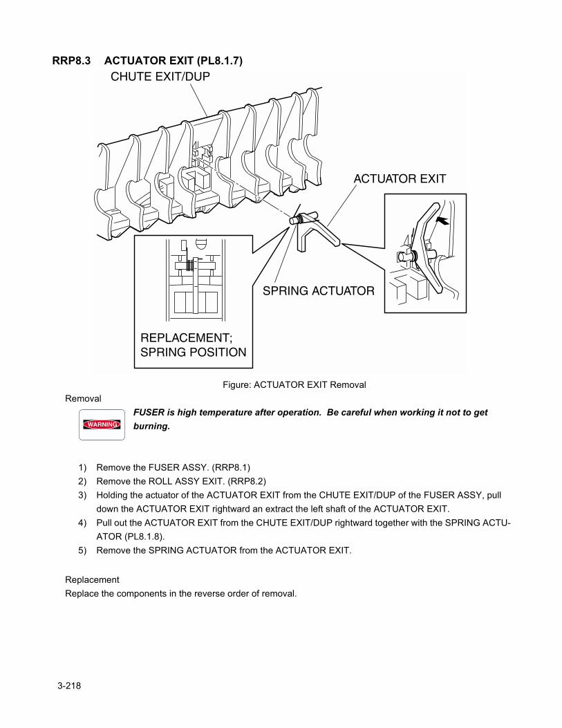
RRP8.3 ACTUATOR EXIT (PL8.1.7)
Figure: ACTUATOR EXIT RemovalRemoval
FUSER is high temperature after operation. Be careful when working it not to get burning.
1) Remove the FUSER ASSY. (RRP8.1)2) Remove the ROLL ASSY EXIT. (RRP8.2)3) Holding the actuator of the ACTUATOR EXIT from the CHUTE EXIT/DUP of the FUSER ASSY, pull
down the ACTUATOR EXIT rightward an extract the left shaft of the ACTUATOR EXIT.4) Pull out the ACTUATOR EXIT from the CHUTE EXIT/DUP rightward together with the SPRING ACTU-
ATOR (PL8.1.8).5) Remove the SPRING ACTUATOR from the ACTUATOR EXIT.
ReplacementReplace the components in the reverse order of removal.
3-218
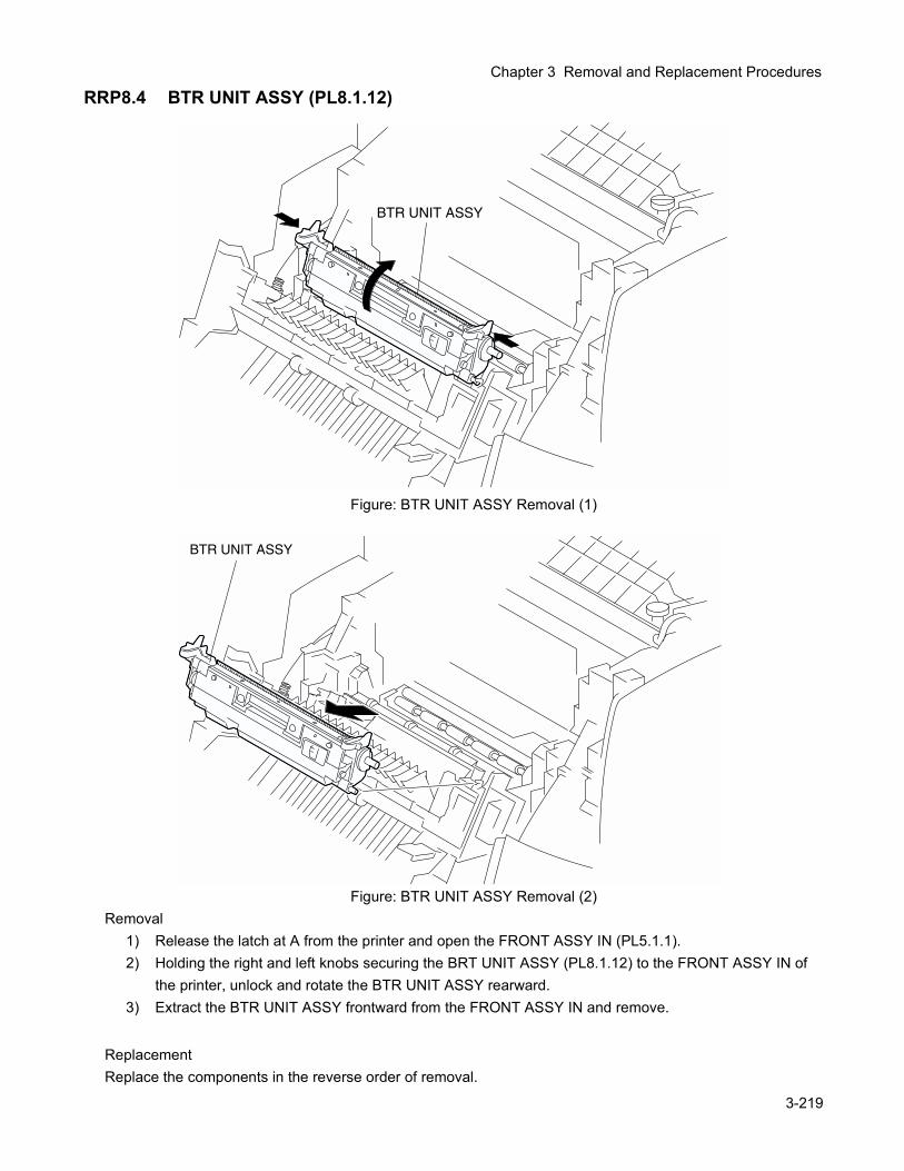
Chapter 3 Removal and Replacement Procedures
RRP8.4 BTR UNIT ASSY (PL8.1.12)
Figure: BTR UNIT ASSY Removal (1)
Figure: BTR UNIT ASSY Removal (2)Removal
1) Release the latch at A from the printer and open the FRONT ASSY IN (PL5.1.1).2) Holding the right and left knobs securing the BRT UNIT ASSY (PL8.1.12) to the FRONT ASSY IN of
the printer, unlock and rotate the BTR UNIT ASSY rearward.3) Extract the BTR UNIT ASSY frontward from the FRONT ASSY IN and remove.
ReplacementReplace the components in the reverse order of removal.
3-219
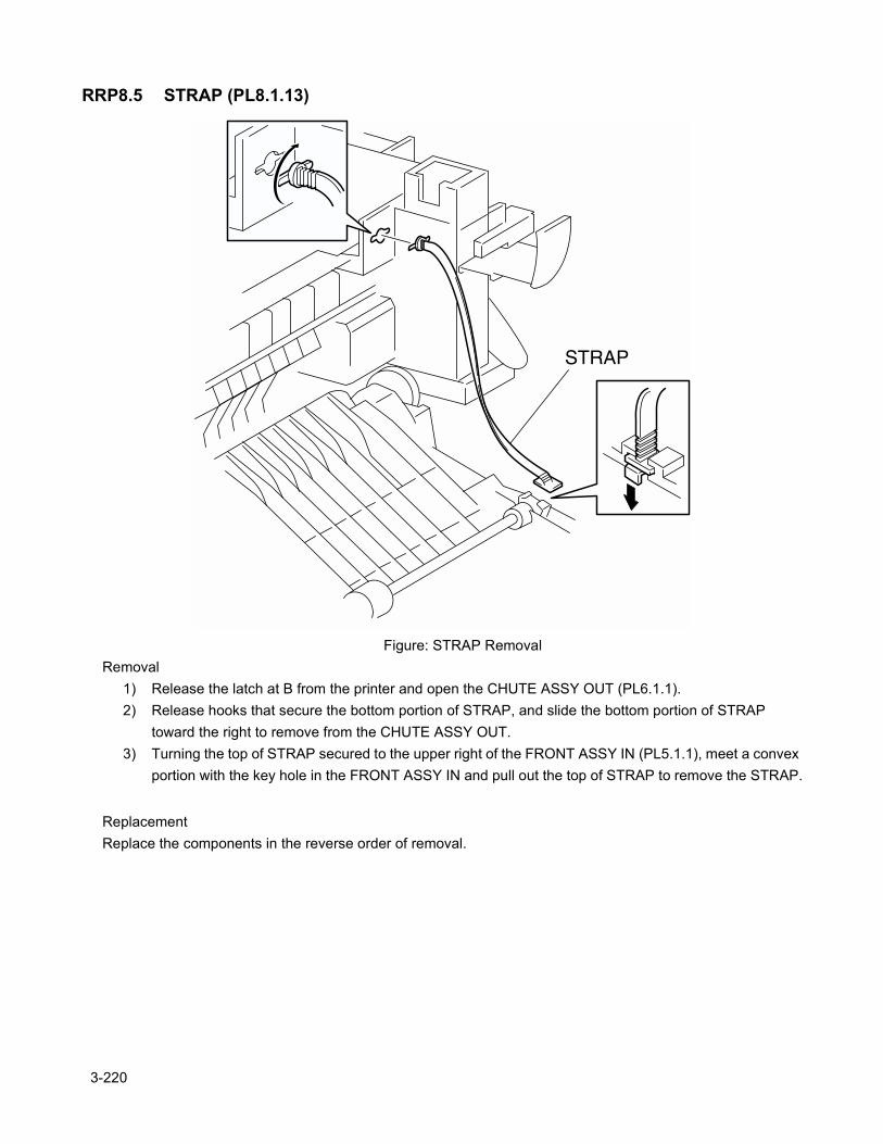
RRP8.5 STRAP (PL8.1.13)
Figure: STRAP RemovalRemoval
1) Release the latch at B from the printer and open the CHUTE ASSY OUT (PL6.1.1).2) Release hooks that secure the bottom portion of STRAP, and slide the bottom portion of STRAP
toward the right to remove from the CHUTE ASSY OUT.3) Turning the top of STRAP secured to the upper right of the FRONT ASSY IN (PL5.1.1), meet a convex
portion with the key hole in the FRONT ASSY IN and pull out the top of STRAP to remove the STRAP.
ReplacementReplace the components in the reverse order of removal.
3-220

Chapter 3 Removal and Replacement Procedures
3-221
Blank page.
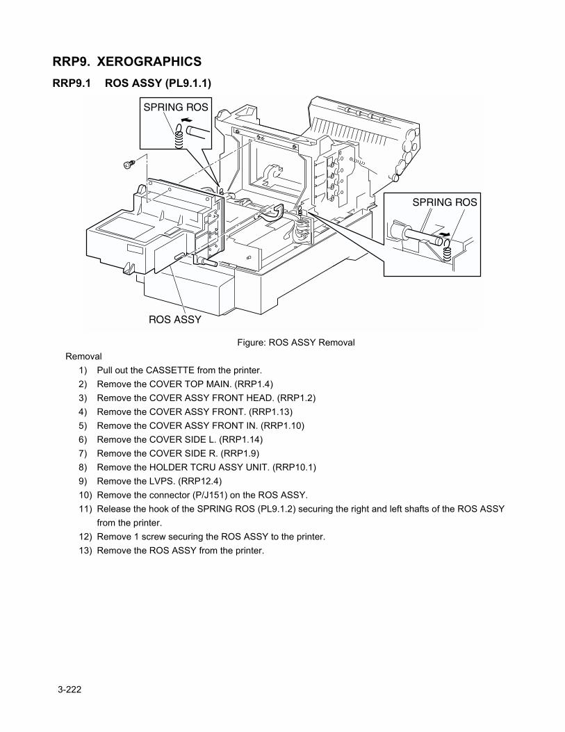
RRP9. XEROGRAPHICSRRP9.1 ROS ASSY (PL9.1.1)
Figure: ROS ASSY RemovalRemoval
1) Pull out the CASSETTE from the printer.2) Remove the COVER TOP MAIN. (RRP1.4)3) Remove the COVER ASSY FRONT HEAD. (RRP1.2)4) Remove the COVER ASSY FRONT. (RRP1.13)5) Remove the COVER ASSY FRONT IN. (RRP1.10)6) Remove the COVER SIDE L. (RRP1.14)7) Remove the COVER SIDE R. (RRP1.9)8) Remove the HOLDER TCRU ASSY UNIT. (RRP10.1)9) Remove the LVPS. (RRP12.4)10) Remove the connector (P/J151) on the ROS ASSY.11) Release the hook of the SPRING ROS (PL9.1.2) securing the right and left shafts of the ROS ASSY
from the printer.12) Remove 1 screw securing the ROS ASSY to the printer.13) Remove the ROS ASSY from the printer.
3-222
Chapter 3 Removal and Replacement Procedures
Replacement1) Align the ROS ASSY with its replace position to the printer.2) Secure the left and right shafts of the ROS ASSY to the printer with the hooks at the top of SPRING
ROS (PL9.1.2).3) Secure the ROS ASSY to the printer with 1 screw.4) Replace the connector (P/J151) to the ROS ASSY.5) Replace the LVPS. (RRP12.4)6) Replace the HOLDER TCRU ASSY UNIT. (RRP10.1)7) Replace the COVER SIDE R. (RRP1.9)8) Replace the COVER SIDE L. (RRP1.14)9) Replace the COVER ASSY FRONT IN. (RRP1.10)10) Replace the COVER ASSY FRONT. (RRP1.13)11) Replace the COVER ASSY FRONT HEAD. (RRP1.2)12) Replace the COVER TOP MAIN. (RRP1.4)13) Replace the CASSETTE to the printer.
3-223
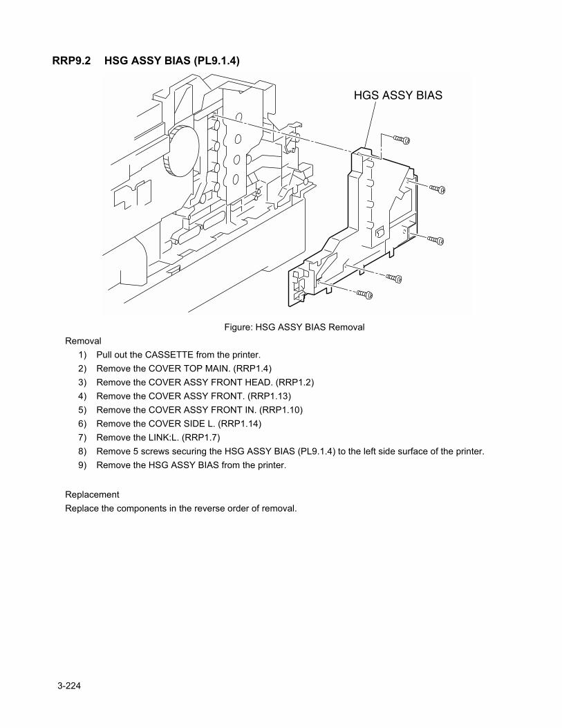
RRP9.2 HSG ASSY BIAS (PL9.1.4)
Figure: HSG ASSY BIAS RemovalRemoval
1) Pull out the CASSETTE from the printer.2) Remove the COVER TOP MAIN. (RRP1.4)3) Remove the COVER ASSY FRONT HEAD. (RRP1.2)4) Remove the COVER ASSY FRONT. (RRP1.13)5) Remove the COVER ASSY FRONT IN. (RRP1.10)6) Remove the COVER SIDE L. (RRP1.14)7) Remove the LINK:L. (RRP1.7)8) Remove 5 screws securing the HSG ASSY BIAS (PL9.1.4) to the left side surface of the printer.9) Remove the HSG ASSY BIAS from the printer.
ReplacementReplace the components in the reverse order of removal.
3-224

Chapter 3 Removal and Replacement Procedures
3-225
Blank page.
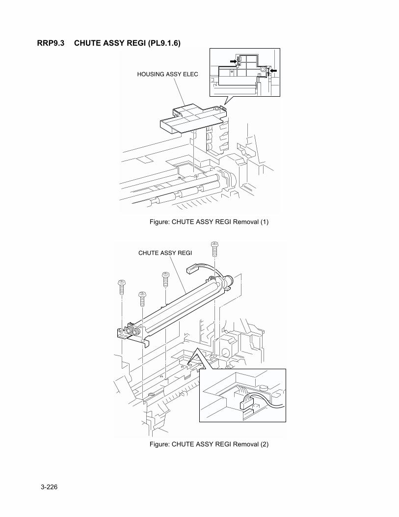
RRP9.3 CHUTE ASSY REGI (PL9.1.6)
Figure: CHUTE ASSY REGI Removal (1)
Figure: CHUTE ASSY REGI Removal (2)
3-226
Chapter 3 Removal and Replacement Procedures
Removal1) Release the latch at A from the printer and open the FRONT ASSY IN (PL5.1.1).1) Remove the PHD.2) Release the hooks at 2 positions securing the HOUSING ASSY ELEC (PL9.1.11) to the printer and
remove the HOUSING ASSY ELEC upward.3) Remove the connector (P/J18) of the CHUTE ASSY REGI from the printer.
Remove the connector (P/J32) of the OHP SENSOR, if installed.
4) Remove 4 screws securing the CHUTE ASSY REGI to the printer.5) Raise the left end of the CHUTE ASSY REGI and pull out the CHUTE ASSY REGI leftward from the
printer.
ReplacementReplace the components in the reverse order of removal.
3-227
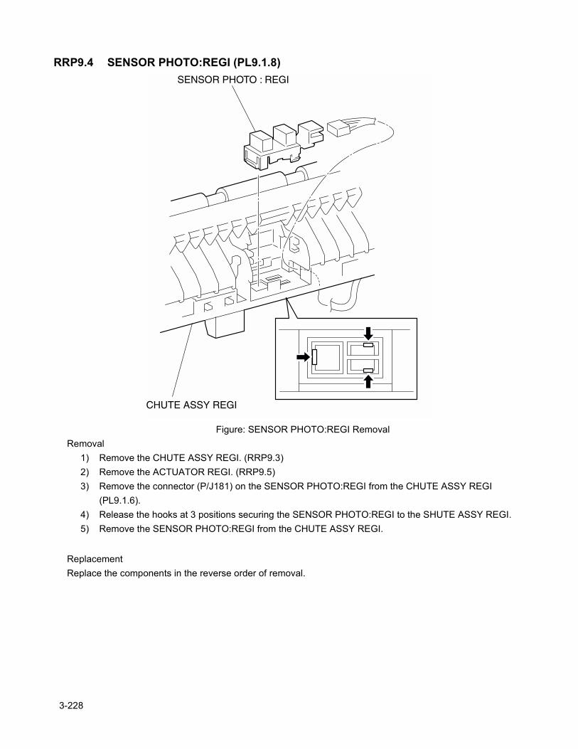
RRP9.4 SENSOR PHOTO:REGI (PL9.1.8)
Figure: SENSOR PHOTO:REGI RemovalRemoval
1) Remove the CHUTE ASSY REGI. (RRP9.3)2) Remove the ACTUATOR REGI. (RRP9.5)3) Remove the connector (P/J181) on the SENSOR PHOTO:REGI from the CHUTE ASSY REGI
(PL9.1.6).4) Release the hooks at 3 positions securing the SENSOR PHOTO:REGI to the SHUTE ASSY REGI.5) Remove the SENSOR PHOTO:REGI from the CHUTE ASSY REGI.
ReplacementReplace the components in the reverse order of removal.
3-228
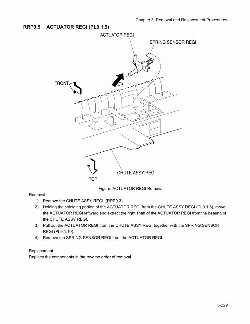
Chapter 3 Removal and Replacement Procedures
RRP9.5 ACTUATOR REGI (PL9.1.9)
Figure: ACTUATOR REGI RemovalRemoval
1) Remove the CHUTE ASSY REGI. (RRP9.3)2) Holding the shielding portion of the ACTUATOR REGI from the CHUTE ASSY REGI (PL9.1.6), move
the ACTUATOR REGI leftward and extract the right shaft of the ACTUATOR REGI from the bearing of the CHUTE ASSY REGI.
3) Pull out the ACTUATOR REGI from the CHUTE ASSY REGI together with the SPRING SENSOR REGI (PL9.1.10).
4) Remove the SPRING SENSOR REGI from the ACTUATOR REGI.
ReplacementReplace the components in the reverse order of removal.
3-229
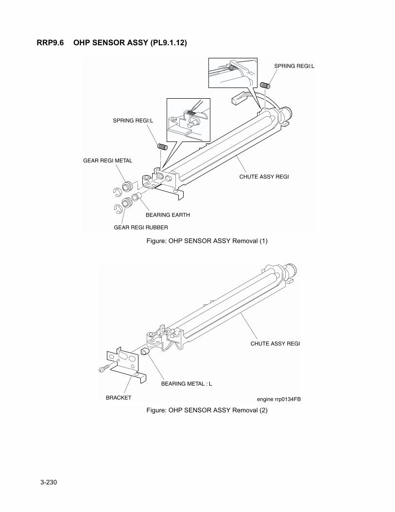
RRP9.6 OHP SENSOR ASSY (PL9.1.12)
Figure: OHP SENSOR ASSY Removal (1)
Figure: OHP SENSOR ASSY Removal (2)
3-230
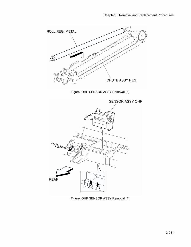
Chapter 3 Removal and Replacement Procedures
Figure: OHP SENSOR ASSY Removal (3)
Figure: OHP SENSOR ASSY Removal (4)
3-231
Removal1) Remove the CHUTE ASSY REGI. (RRP9.3)2) Remove an E-ring that secures the GEAR REGI METAL from the CHUTE ASSY REGI (PL9.1.6), and
pull out the GEAR REGI METAL of the left shaft of the ROLL REGI METAL.3) Remove an E-ring that secures the GEAR REGI RUBBER from the CHUTE ASSY REGI, and pull out
the GEAR REGI RUBBER of the left shaft of the ROLL REGI RUBBER.4) Pull out the BEARING EARTH that secures the left shaft of the ROLL REGI RUBBER on the CHUTE
ASSY REGI.In the following steps, take care not to lose the SPRING REGI:R and SPRING REGI:L as they will spring.
5) Remove the SPRING REGI:L from the right side of CHUTE ASSY REGI using a mini screwdriver.6) From the left side surface of CHUTE ASSY REGI, remove a screw that secures the BRACKET ASSY.7) Pull out the BEARING METAL L (black) that secures the left shaft of ROLL REGI METAL on the
CHUTE ASSY REGI.8) Raising the left shaft of ROLL REGI METAL, pull out the ROLL REGI METAL together with the BEAR-
ING METAL R (white) on the right shaft from the CHUTE ASSY REGI.9) Release the hook at 2 position on the bottom of CHUTE ASSY REGI that secure the OHP SENSOR
ASSY from the CHUTE ASSY REGI.10) Remove the OHP SENSOR ASSY from the CHUTE ASSY REGI.
ReplacementReplace the components in the reverse order of removal.
3-232

Chapter 3 Removal and Replacement Procedures
Blank page.
3-233
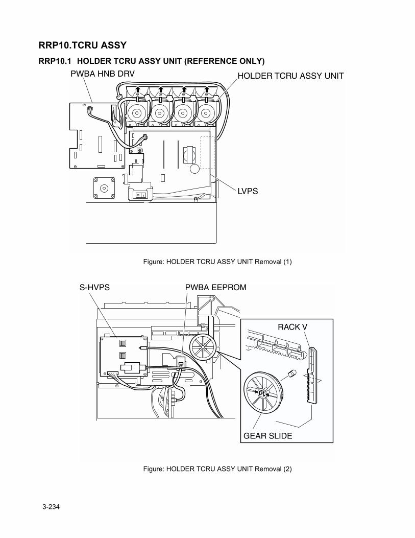
RRP10.TCRU ASSYRRP10.1 HOLDER TCRU ASSY UNIT (REFERENCE ONLY)
Figure: HOLDER TCRU ASSY UNIT Removal (1)
Figure: HOLDER TCRU ASSY UNIT Removal (2)
3-234
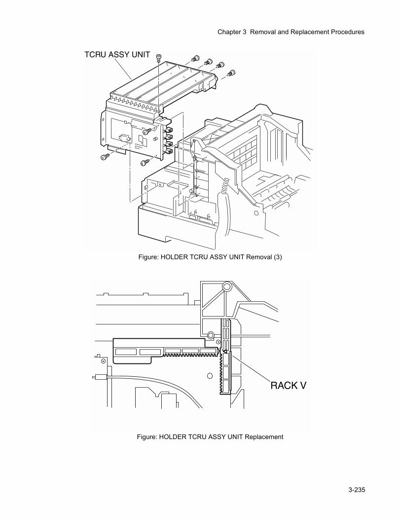
Chapter 3 Removal and Replacement Procedures
Figure: HOLDER TCRU ASSY UNIT Removal (3)
Figure: HOLDER TCRU ASSY UNIT Replacement
3-235
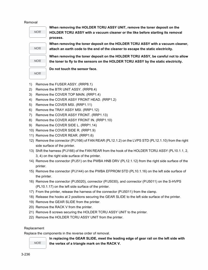
RemovalWhen removing the HOLDER TCRU ASSY UNIT, remove the toner deposit on the HOLDER TCRU ASSY with a vacuum cleaner or the like before starting its removal process.
When removing the toner deposit on the HOLDER TCRU ASSY with a vacuum cleaner, attach an earth code to the end of the cleaner to escape the static electricity.
When removing the toner deposit on the HOLDER TCRU ASSY, be careful not to allow the toner to fly to the sensors on the HOLDER TCRU ASSY by the static electricity.
Do not touch the sensor face.
1) Remove the FUSER ASSY. (RRP8.1)2) Remove the BTR UNIT ASSY. (RRP8.4)3) Remove the COVER TOP MAIN. (RRP1.4)4) Remove the COVER ASSY FRONT HEAD. (RRP1.2)5) Remove the COVER MSI. (RRP1.11)6) Remove the TRAY ASSY MSI. (RRP1.12)7) Remove the COVER ASSY FRONT. (RRP1.13)8) Remove the COVER ASSY FRONT IN. (RRP1.10)9) Remove the COVER SIDE L. (RRP1.14)10) Remove the COVER SIDE R. (RRP1.9)11) Remove the COVER REAR. (RRP1.6)12) Remove the connector (P/J166) of FAN REAR (PL12.1.2) on the LVPS STD (PL12.1.10) from the right
side surface of the printer.13) Shift the harness (P/J166) of the FAN REAR from the hook of the HOLDER TCRU ASSY (PL10.1.1, 2,
3, 4) on the right side surface of the printer.14) Remove the connector (P/J51) on the PWBA HNB DRV (PL12.1.12) from the right side surface of the
printer.15) Remove the connector (P/J144) on the PWBA EFPROM STD (PL10.1.16) on the left side surface of
the printer.16) Remove the connector (P/J5020), connector (P/J5030), and connector (P/J5011) on the S-HVPS
(PL10.1.17) on the left side surface of the printer.17) From the printer, release the harness of the connector (P/J5011) from the clamp. 18) Release the hooks at 2 positions securing the GEAR SLIDE to the left side surface of the printer.19) Remove the GEAR SLIDE from the printer.20) Remove the RACK V from the printer.21) Remove 8 screws securing the HOLDER TCRU ASSY UNIT to the printer.22) Remove the HOLDER TCRU ASSY UNIT from the printer.
ReplacementReplace the components in the reverse order of removal.
In replacing the GEAR SLIDE, meet the leading edge of gear rail on the left side with the vertex of a triangle mark on the RACK V.
3-236
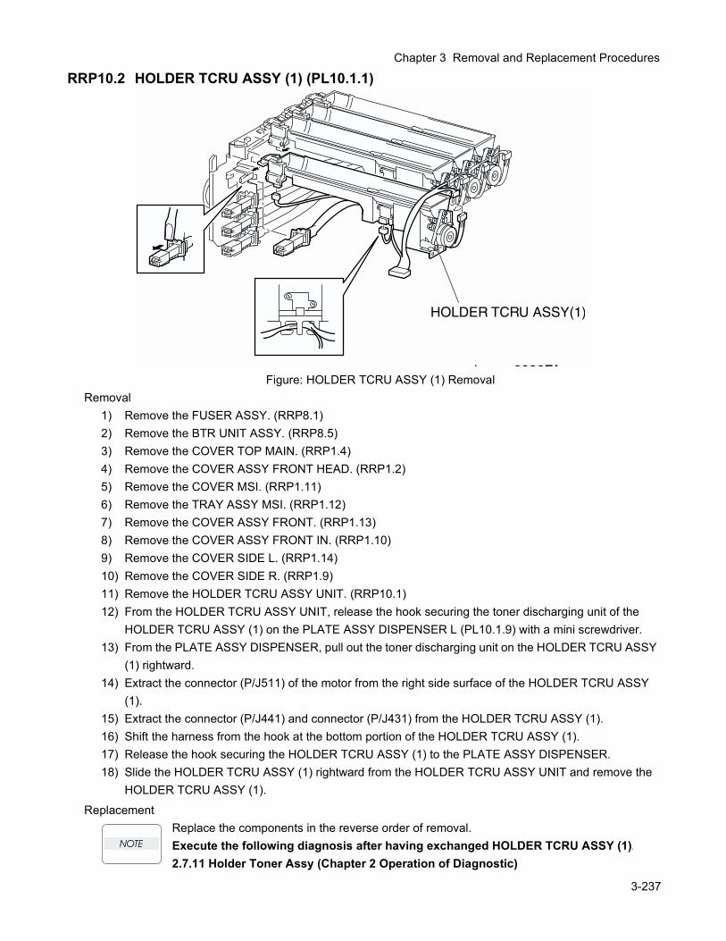
Chapter 3 Removal and Replacement Procedures
RRP10.2 HOLDER TCRU ASSY (1) (PL10.1.1)
Figure: HOLDER TCRU ASSY (1) RemovalRemoval
1) Remove the FUSER ASSY. (RRP8.1)2) Remove the BTR UNIT ASSY. (RRP8.5)3) Remove the COVER TOP MAIN. (RRP1.4)4) Remove the COVER ASSY FRONT HEAD. (RRP1.2)5) Remove the COVER MSI. (RRP1.11)6) Remove the TRAY ASSY MSI. (RRP1.12)7) Remove the COVER ASSY FRONT. (RRP1.13)8) Remove the COVER ASSY FRONT IN. (RRP1.10)9) Remove the COVER SIDE L. (RRP1.14)10) Remove the COVER SIDE R. (RRP1.9)11) Remove the HOLDER TCRU ASSY UNIT. (RRP10.1)12) From the HOLDER TCRU ASSY UNIT, release the hook securing the toner discharging unit of the
HOLDER TCRU ASSY (1) on the PLATE ASSY DISPENSER L (PL10.1.9) with a mini screwdriver.13) From the PLATE ASSY DISPENSER, pull out the toner discharging unit on the HOLDER TCRU ASSY
(1) rightward.14) Extract the connector (P/J511) of the motor from the right side surface of the HOLDER TCRU ASSY
(1).15) Extract the connector (P/J441) and connector (P/J431) from the HOLDER TCRU ASSY (1).16) Shift the harness from the hook at the bottom portion of the HOLDER TCRU ASSY (1).17) Release the hook securing the HOLDER TCRU ASSY (1) to the PLATE ASSY DISPENSER.18) Slide the HOLDER TCRU ASSY (1) rightward from the HOLDER TCRU ASSY UNIT and remove the
HOLDER TCRU ASSY (1).Replacement
Replace the components in the reverse order of removal.Execute the following diagnosis after having exchanged HOLDER TCRU ASSY (1).
2.7.11 Holder Toner Assy (Chapter 2 Operation of Diagnostic)
3-237
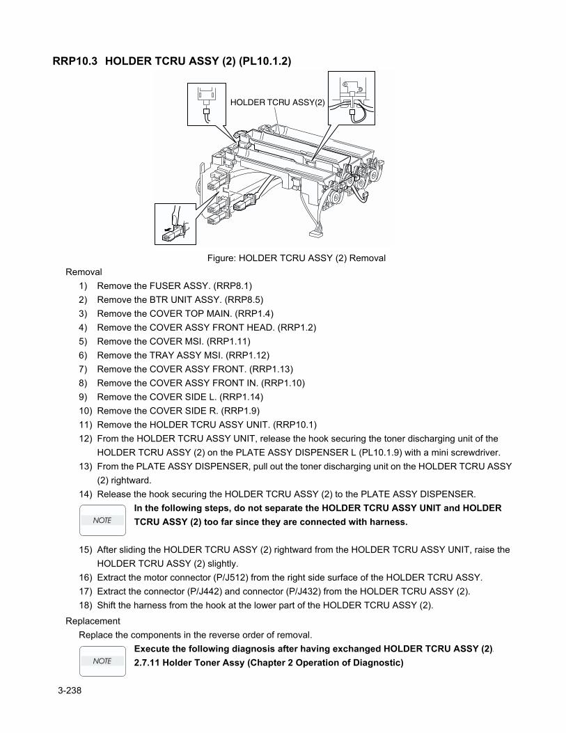
RRP10.3 HOLDER TCRU ASSY (2) (PL10.1.2)
Figure: HOLDER TCRU ASSY (2) RemovalRemoval
1) Remove the FUSER ASSY. (RRP8.1)2) Remove the BTR UNIT ASSY. (RRP8.5)3) Remove the COVER TOP MAIN. (RRP1.4)4) Remove the COVER ASSY FRONT HEAD. (RRP1.2)5) Remove the COVER MSI. (RRP1.11)6) Remove the TRAY ASSY MSI. (RRP1.12)7) Remove the COVER ASSY FRONT. (RRP1.13)8) Remove the COVER ASSY FRONT IN. (RRP1.10)9) Remove the COVER SIDE L. (RRP1.14)10) Remove the COVER SIDE R. (RRP1.9)11) Remove the HOLDER TCRU ASSY UNIT. (RRP10.1)12) From the HOLDER TCRU ASSY UNIT, release the hook securing the toner discharging unit of the
HOLDER TCRU ASSY (2) on the PLATE ASSY DISPENSER L (PL10.1.9) with a mini screwdriver.13) From the PLATE ASSY DISPENSER, pull out the toner discharging unit on the HOLDER TCRU ASSY
(2) rightward.14) Release the hook securing the HOLDER TCRU ASSY (2) to the PLATE ASSY DISPENSER.
In the following steps, do not separate the HOLDER TCRU ASSY UNIT and HOLDER TCRU ASSY (2) too far since they are connected with harness.
15) After sliding the HOLDER TCRU ASSY (2) rightward from the HOLDER TCRU ASSY UNIT, raise the HOLDER TCRU ASSY (2) slightly.
16) Extract the motor connector (P/J512) from the right side surface of the HOLDER TCRU ASSY.17) Extract the connector (P/J442) and connector (P/J432) from the HOLDER TCRU ASSY (2).18) Shift the harness from the hook at the lower part of the HOLDER TCRU ASSY (2).
ReplacementReplace the components in the reverse order of removal.
Execute the following diagnosis after having exchanged HOLDER TCRU ASSY (2).
2.7.11 Holder Toner Assy (Chapter 2 Operation of Diagnostic)
3-238
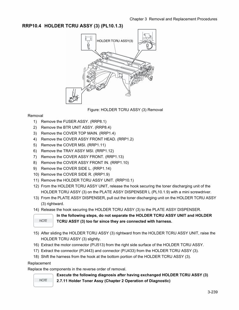
Chapter 3 Removal and Replacement Procedures
RRP10.4 HOLDER TCRU ASSY (3) (PL10.1.3)
Figure: HOLDER TCRU ASSY (3) RemovalRemoval
1) Remove the FUSER ASSY. (RRP8.1)2) Remove the BTR UNIT ASSY. (RRP8.4)3) Remove the COVER TOP MAIN. (RRP1.4)4) Remove the COVER ASSY FRONT HEAD. (RRP1.2)5) Remove the COVER MSI. (RRP1.11)6) Remove the TRAY ASSY MSI. (RRP1.12)7) Remove the COVER ASSY FRONT. (RRP1.13)8) Remove the COVER ASSY FRONT IN. (RRP1.10)9) Remove the COVER SIDE L. (RRP1.14)10) Remove the COVER SIDE R. (RRP1.9)11) Remove the HOLDER TCRU ASSY UNIT. (RRP10.1)12) From the HOLDER TCRU ASSY UNIT, release the hook securing the toner discharging unit of the
HOLDER TCRU ASSY (3) on the PLATE ASSY DISPENSER L (PL10.1.9) with a mini screwdriver.13) From the PLATE ASSY DISPENSER, pull out the toner discharging unit on the HOLDER TCRU ASSY
(3) rightward.14) Release the hook securing the HOLDER TCRU ASSY (3) to the PLATE ASSY DISPENSER.
In the following steps, do not separate the HOLDER TCRU ASSY UNIT and HOLDER TCRU ASSY (3) too far since they are connected with harness.
15) After sliding the HOLDER TCRU ASSY (3) rightward from the HOLDER TCRU ASSY UNIT, raise the HOLDER TCRU ASSY (3) slightly.
16) Extract the motor connector (P/J513) from the right side surface of the HOLDER TCRU ASSY.17) Extract the connector (P/J443) and connector (P/J433) from the HOLDER TCRU ASSY (3).18) Shift the harness from the hook at the bottom portion of the HOLDER TCRU ASSY (3).
ReplacementReplace the components in the reverse order of removal.
Execute the following diagnosis after having exchanged HOLDER TCRU ASSY (3).
2.7.11 Holder Toner Assy (Chapter 2 Operation of Diagnostic)
3-239
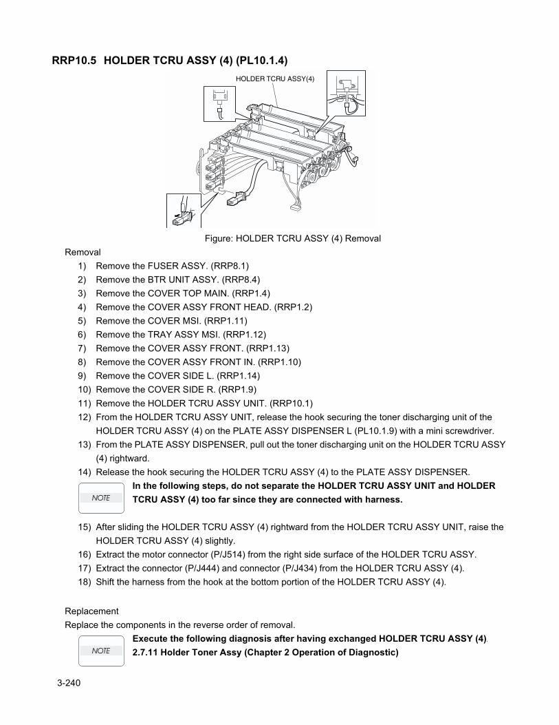
RRP10.5 HOLDER TCRU ASSY (4) (PL10.1.4)
Figure: HOLDER TCRU ASSY (4) RemovalRemoval
1) Remove the FUSER ASSY. (RRP8.1)2) Remove the BTR UNIT ASSY. (RRP8.4)3) Remove the COVER TOP MAIN. (RRP1.4)4) Remove the COVER ASSY FRONT HEAD. (RRP1.2)5) Remove the COVER MSI. (RRP1.11)6) Remove the TRAY ASSY MSI. (RRP1.12)7) Remove the COVER ASSY FRONT. (RRP1.13)8) Remove the COVER ASSY FRONT IN. (RRP1.10)9) Remove the COVER SIDE L. (RRP1.14)10) Remove the COVER SIDE R. (RRP1.9)11) Remove the HOLDER TCRU ASSY UNIT. (RRP10.1)12) From the HOLDER TCRU ASSY UNIT, release the hook securing the toner discharging unit of the
HOLDER TCRU ASSY (4) on the PLATE ASSY DISPENSER L (PL10.1.9) with a mini screwdriver.13) From the PLATE ASSY DISPENSER, pull out the toner discharging unit on the HOLDER TCRU ASSY
(4) rightward.14) Release the hook securing the HOLDER TCRU ASSY (4) to the PLATE ASSY DISPENSER.
In the following steps, do not separate the HOLDER TCRU ASSY UNIT and HOLDER TCRU ASSY (4) too far since they are connected with harness.
15) After sliding the HOLDER TCRU ASSY (4) rightward from the HOLDER TCRU ASSY UNIT, raise the HOLDER TCRU ASSY (4) slightly.
16) Extract the motor connector (P/J514) from the right side surface of the HOLDER TCRU ASSY.17) Extract the connector (P/J444) and connector (P/J434) from the HOLDER TCRU ASSY (4).18) Shift the harness from the hook at the bottom portion of the HOLDER TCRU ASSY (4).
ReplacementReplace the components in the reverse order of removal.
Execute the following diagnosis after having exchanged HOLDER TCRU ASSY (4).
2.7.11 Holder Toner Assy (Chapter 2 Operation of Diagnostic)
3-240
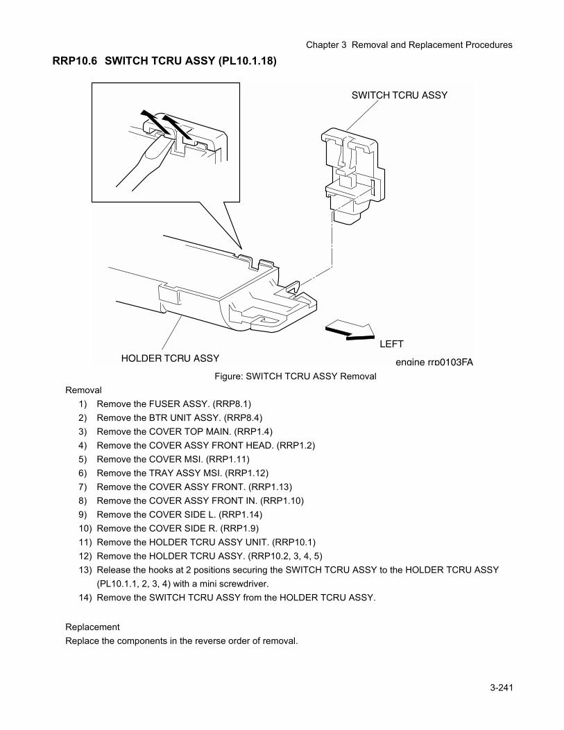
Chapter 3 Removal and Replacement Procedures
RRP10.6 SWITCH TCRU ASSY (PL10.1.18)
Figure: SWITCH TCRU ASSY RemovalRemoval
1) Remove the FUSER ASSY. (RRP8.1)2) Remove the BTR UNIT ASSY. (RRP8.4)3) Remove the COVER TOP MAIN. (RRP1.4)4) Remove the COVER ASSY FRONT HEAD. (RRP1.2)5) Remove the COVER MSI. (RRP1.11)6) Remove the TRAY ASSY MSI. (RRP1.12)7) Remove the COVER ASSY FRONT. (RRP1.13)8) Remove the COVER ASSY FRONT IN. (RRP1.10)9) Remove the COVER SIDE L. (RRP1.14)10) Remove the COVER SIDE R. (RRP1.9)11) Remove the HOLDER TCRU ASSY UNIT. (RRP10.1)12) Remove the HOLDER TCRU ASSY. (RRP10.2, 3, 4, 5)13) Release the hooks at 2 positions securing the SWITCH TCRU ASSY to the HOLDER TCRU ASSY
(PL10.1.1, 2, 3, 4) with a mini screwdriver.14) Remove the SWITCH TCRU ASSY from the HOLDER TCRU ASSY.
ReplacementReplace the components in the reverse order of removal.
3-241
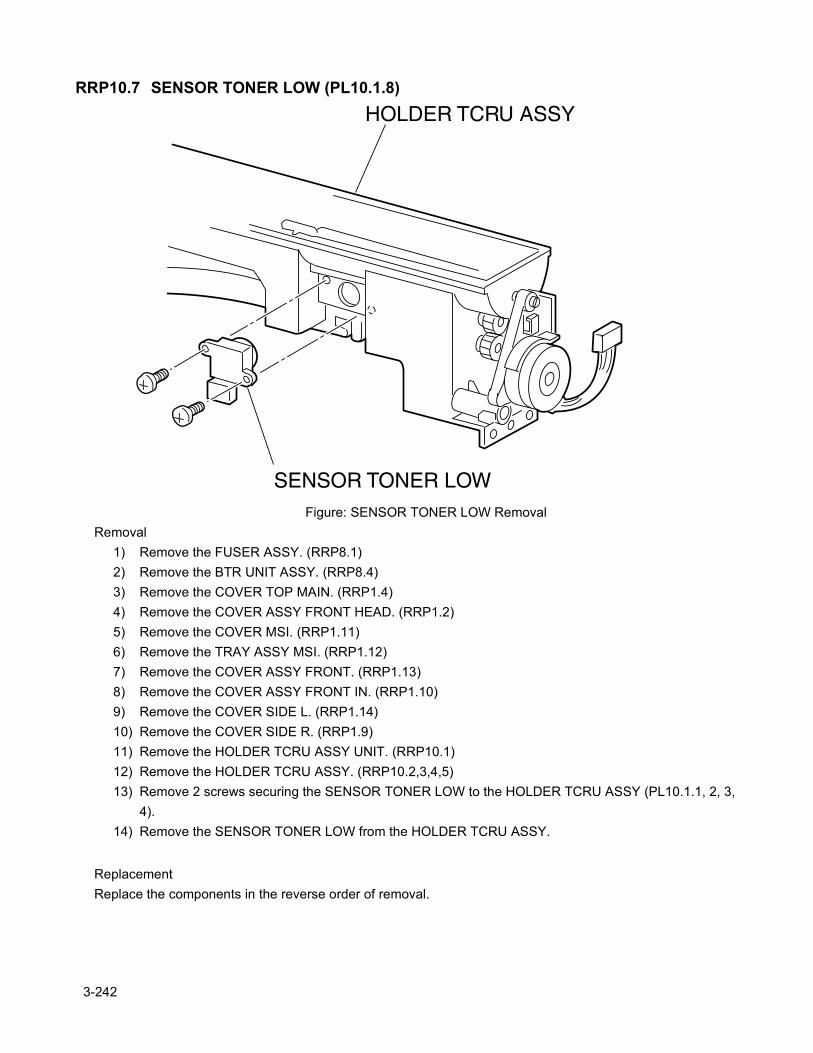
RRP10.7 SENSOR TONER LOW (PL10.1.8)
Figure: SENSOR TONER LOW RemovalRemoval
1) Remove the FUSER ASSY. (RRP8.1)2) Remove the BTR UNIT ASSY. (RRP8.4)3) Remove the COVER TOP MAIN. (RRP1.4)4) Remove the COVER ASSY FRONT HEAD. (RRP1.2)5) Remove the COVER MSI. (RRP1.11)6) Remove the TRAY ASSY MSI. (RRP1.12)7) Remove the COVER ASSY FRONT. (RRP1.13)8) Remove the COVER ASSY FRONT IN. (RRP1.10)9) Remove the COVER SIDE L. (RRP1.14)10) Remove the COVER SIDE R. (RRP1.9)11) Remove the HOLDER TCRU ASSY UNIT. (RRP10.1)12) Remove the HOLDER TCRU ASSY. (RRP10.2,3,4,5)13) Remove 2 screws securing the SENSOR TONER LOW to the HOLDER TCRU ASSY (PL10.1.1, 2, 3,
4).14) Remove the SENSOR TONER LOW from the HOLDER TCRU ASSY.
ReplacementReplace the components in the reverse order of removal.
3-242
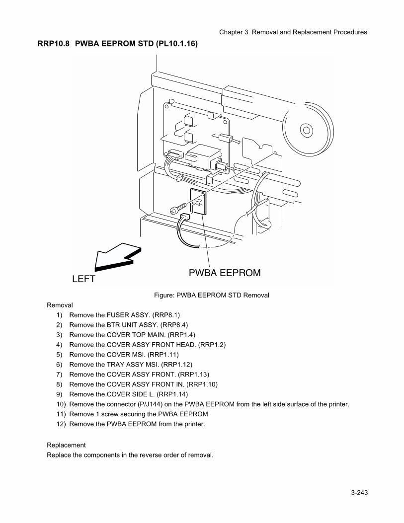
Chapter 3 Removal and Replacement Procedures
RRP10.8 PWBA EEPROM STD (PL10.1.16)
Figure: PWBA EEPROM STD RemovalRemoval
1) Remove the FUSER ASSY. (RRP8.1)2) Remove the BTR UNIT ASSY. (RRP8.4)3) Remove the COVER TOP MAIN. (RRP1.4)4) Remove the COVER ASSY FRONT HEAD. (RRP1.2)5) Remove the COVER MSI. (RRP1.11)6) Remove the TRAY ASSY MSI. (RRP1.12)7) Remove the COVER ASSY FRONT. (RRP1.13)8) Remove the COVER ASSY FRONT IN. (RRP1.10)9) Remove the COVER SIDE L. (RRP1.14)10) Remove the connector (P/J144) on the PWBA EEPROM from the left side surface of the printer.11) Remove 1 screw securing the PWBA EEPROM.12) Remove the PWBA EEPROM from the printer.
ReplacementReplace the components in the reverse order of removal.
3-243
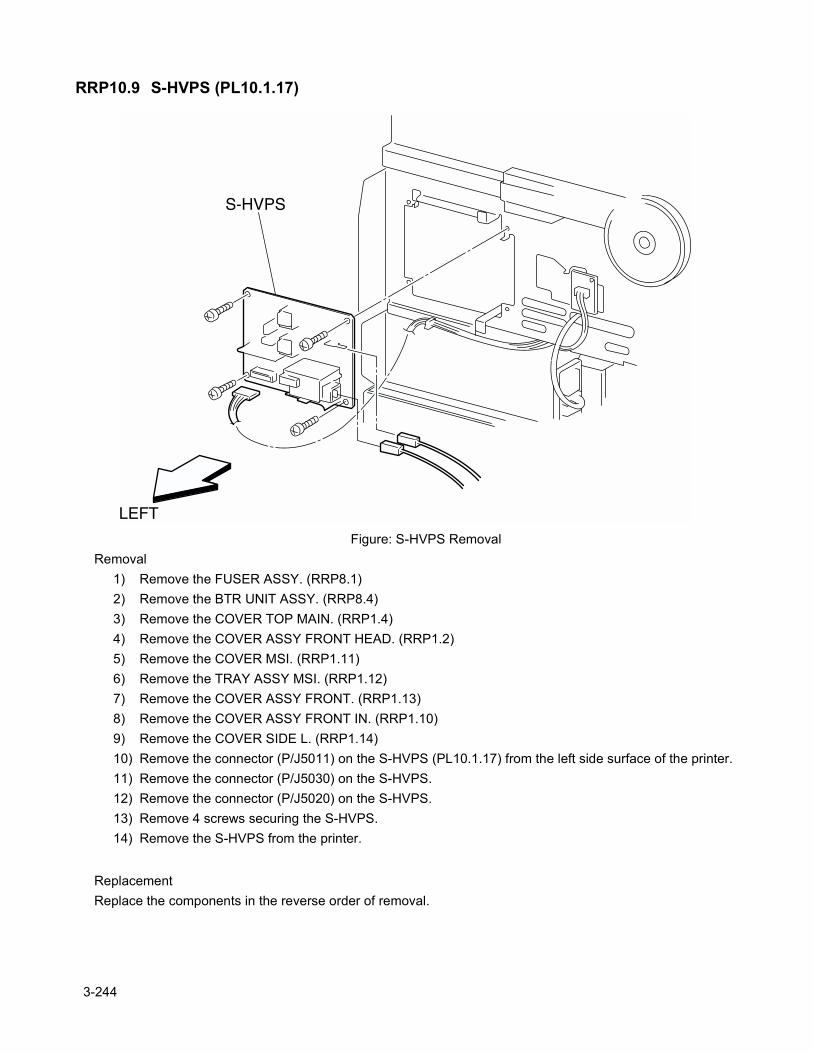
RRP10.9 S-HVPS (PL10.1.17)
Figure: S-HVPS RemovalRemoval
1) Remove the FUSER ASSY. (RRP8.1)2) Remove the BTR UNIT ASSY. (RRP8.4)3) Remove the COVER TOP MAIN. (RRP1.4)4) Remove the COVER ASSY FRONT HEAD. (RRP1.2)5) Remove the COVER MSI. (RRP1.11)6) Remove the TRAY ASSY MSI. (RRP1.12)7) Remove the COVER ASSY FRONT. (RRP1.13)8) Remove the COVER ASSY FRONT IN. (RRP1.10)9) Remove the COVER SIDE L. (RRP1.14)10) Remove the connector (P/J5011) on the S-HVPS (PL10.1.17) from the left side surface of the printer.11) Remove the connector (P/J5030) on the S-HVPS.12) Remove the connector (P/J5020) on the S-HVPS.13) Remove 4 screws securing the S-HVPS.14) Remove the S-HVPS from the printer.
ReplacementReplace the components in the reverse order of removal.
3-244
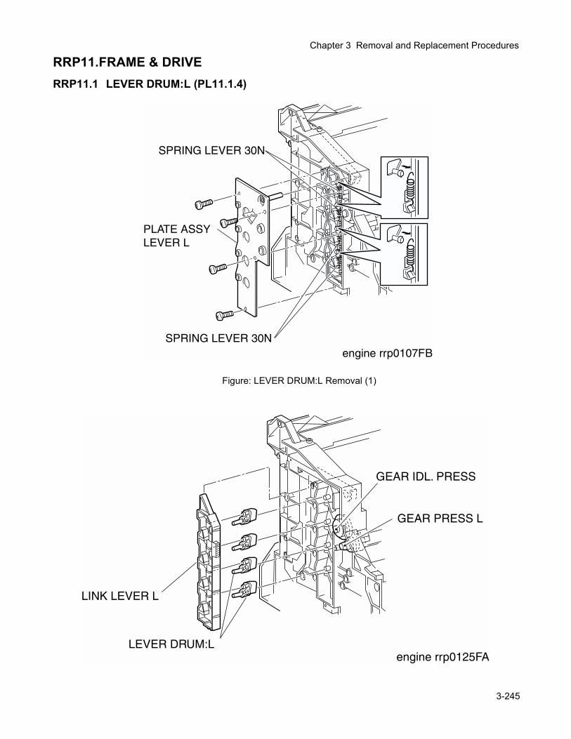
Chapter 3 Removal and Replacement Procedures
RRP11.FRAME & DRIVERRP11.1 LEVER DRUM:L (PL11.1.4)
Figure: LEVER DRUM:L Removal (1)
3-245
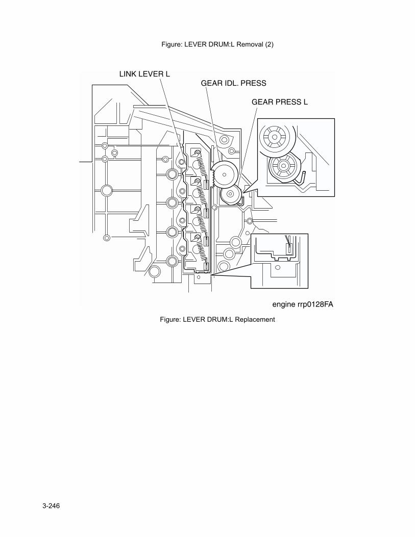
Figure: LEVER DRUM:L Removal (2)
Figure: LEVER DRUM:L Replacement
3-246
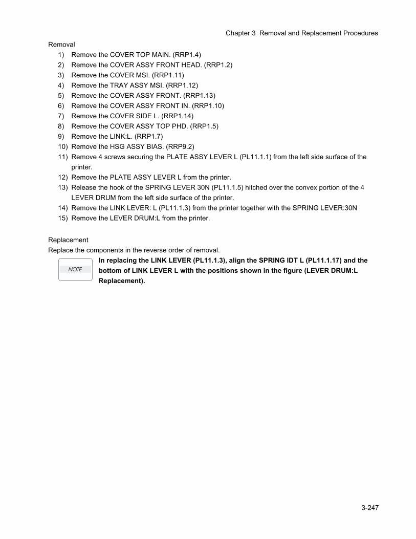
Chapter 3 Removal and Replacement Procedures
Removal1) Remove the COVER TOP MAIN. (RRP1.4)2) Remove the COVER ASSY FRONT HEAD. (RRP1.2)3) Remove the COVER MSI. (RRP1.11)4) Remove the TRAY ASSY MSI. (RRP1.12)5) Remove the COVER ASSY FRONT. (RRP1.13)6) Remove the COVER ASSY FRONT IN. (RRP1.10)7) Remove the COVER SIDE L. (RRP1.14)8) Remove the COVER ASSY TOP PHD. (RRP1.5)9) Remove the LINK:L. (RRP1.7)10) Remove the HSG ASSY BIAS. (RRP9.2)11) Remove 4 screws securing the PLATE ASSY LEVER L (PL11.1.1) from the left side surface of the
printer.12) Remove the PLATE ASSY LEVER L from the printer.13) Release the hook of the SPRING LEVER 30N (PL11.1.5) hitched over the convex portion of the 4
LEVER DRUM from the left side surface of the printer.14) Remove the LINK LEVER: L (PL11.1.3) from the printer together with the SPRING LEVER:30N 15) Remove the LEVER DRUM:L from the printer.
ReplacementReplace the components in the reverse order of removal.
In replacing the LINK LEVER (PL11.1.3), align the SPRING IDT L (PL11.1.17) and the bottom of LINK LEVER L with the positions shown in the figure (LEVER DRUM:L Replacement).
3-247
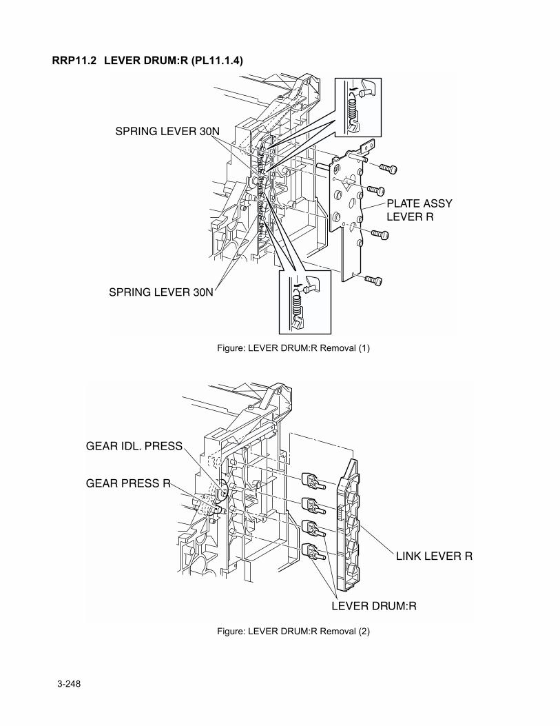
RRP11.2 LEVER DRUM:R (PL11.1.4)
Figure: LEVER DRUM:R Removal (1)
Figure: LEVER DRUM:R Removal (2)
3-248
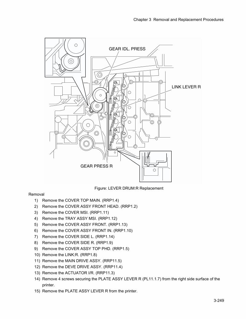
Chapter 3 Removal and Replacement Procedures
Figure: LEVER DRUM:R ReplacementRemoval
1) Remove the COVER TOP MAIN. (RRP1.4)2) Remove the COVER ASSY FRONT HEAD. (RRP1.2)3) Remove the COVER MSI. (RRP1.11)4) Remove the TRAY ASSY MSI. (RRP1.12)5) Remove the COVER ASSY FRONT. (RRP1.13)6) Remove the COVER ASSY FRONT IN. (RRP1.10)7) Remove the COVER SIDE L. (RRP1.14)8) Remove the COVER SIDE R. (RRP1.9)9) Remove the COVER ASSY TOP PHD. (RRP1.5)10) Remove the LINK:R. (RRP1.8)11) Remove the MAIN DRIVE ASSY. (RRP11.5)12) Remove the DEVE DRIVE ASSY. (RRP11.4)13) Remove the ACTUATOR I/R. (RRP11.3)14) Remove 4 screws securing the PLATE ASSY LEVER R (PL11.1.7) from the right side surface of the
printer.15) Remove the PLATE ASSY LEVER R from the printer.
3-249
16) Release the hook of the SPRING LEVER 30N (PL11.1.5) hitched over the convex portion of the 4 LEVER DRUM:R from the right side surface of the printer.
17) Remove the LINK LEVER:R (PL11.1.6) from the printer together with the SPRING LEVER 30N.18) Remove the LEVER DRUM:R from the printer.
ReplacementReplace the components in the reverse order of removal.
In replacing the LINK LEVER R (PL11.1.6), align the SPRING IDT R (PL11.1.12) and the bottom of LINK LEVER L with the positions shown in the figure (LEVER DRUM:L Replacement).
3-250
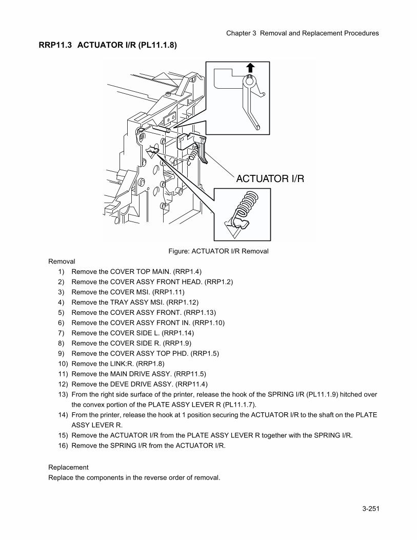
Chapter 3 Removal and Replacement Procedures
RRP11.3 ACTUATOR I/R (PL11.1.8)
Figure: ACTUATOR I/R RemovalRemoval
1) Remove the COVER TOP MAIN. (RRP1.4)2) Remove the COVER ASSY FRONT HEAD. (RRP1.2)3) Remove the COVER MSI. (RRP1.11)4) Remove the TRAY ASSY MSI. (RRP1.12)5) Remove the COVER ASSY FRONT. (RRP1.13)6) Remove the COVER ASSY FRONT IN. (RRP1.10)7) Remove the COVER SIDE L. (RRP1.14)8) Remove the COVER SIDE R. (RRP1.9)9) Remove the COVER ASSY TOP PHD. (RRP1.5)10) Remove the LINK:R. (RRP1.8)11) Remove the MAIN DRIVE ASSY. (RRP11.5)12) Remove the DEVE DRIVE ASSY. (RRP11.4)13) From the right side surface of the printer, release the hook of the SPRING I/R (PL11.1.9) hitched over
the convex portion of the PLATE ASSY LEVER R (PL11.1.7).14) From the printer, release the hook at 1 position securing the ACTUATOR I/R to the shaft on the PLATE
ASSY LEVER R.15) Remove the ACTUATOR I/R from the PLATE ASSY LEVER R together with the SPRING I/R.16) Remove the SPRING I/R from the ACTUATOR I/R.
ReplacementReplace the components in the reverse order of removal.
3-251
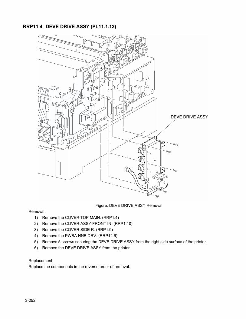
RRP11.4 DEVE DRIVE ASSY (PL11.1.13)
Figure: DEVE DRIVE ASSY RemovalRemoval
1) Remove the COVER TOP MAIN. (RRP1.4)2) Remove the COVER ASSY FRONT IN. (RRP1.10)3) Remove the COVER SIDE R. (RRP1.9)4) Remove the PWBA HNB DRV. (RRP12.6)5) Remove 5 screws securing the DEVE DRIVE ASSY from the right side surface of the printer.6) Remove the DEVE DRIVE ASSY from the printer.
ReplacementReplace the components in the reverse order of removal.
3-252
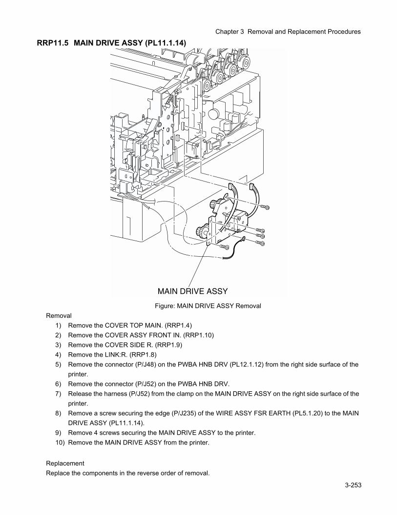
Chapter 3 Removal and Replacement Procedures
RRP11.5 MAIN DRIVE ASSY (PL11.1.14)
Figure: MAIN DRIVE ASSY RemovalRemoval
1) Remove the COVER TOP MAIN. (RRP1.4)2) Remove the COVER ASSY FRONT IN. (RRP1.10)3) Remove the COVER SIDE R. (RRP1.9)4) Remove the LINK:R. (RRP1.8)5) Remove the connector (P/J48) on the PWBA HNB DRV (PL12.1.12) from the right side surface of the
printer.6) Remove the connector (P/J52) on the PWBA HNB DRV.7) Release the harness (P/J52) from the clamp on the MAIN DRIVE ASSY on the right side surface of the
printer.8) Remove a screw securing the edge (P/J235) of the WIRE ASSY FSR EARTH (PL5.1.20) to the MAIN
DRIVE ASSY (PL11.1.14).9) Remove 4 screws securing the MAIN DRIVE ASSY to the printer.10) Remove the MAIN DRIVE ASSY from the printer.
ReplacementReplace the components in the reverse order of removal.
3-253
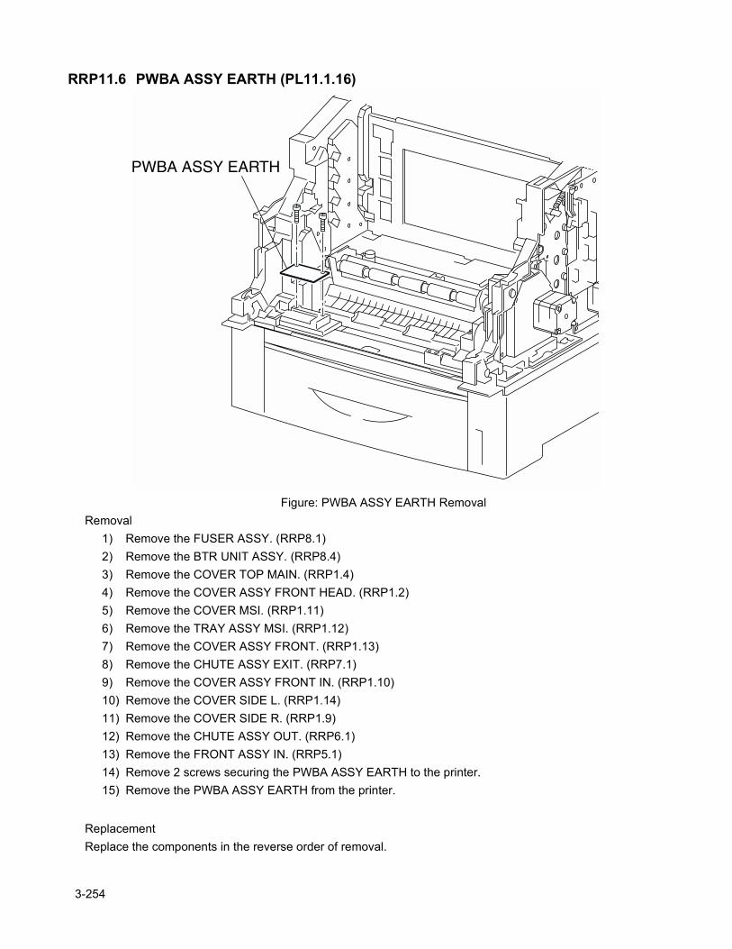
RRP11.6 PWBA ASSY EARTH (PL11.1.16)
Figure: PWBA ASSY EARTH RemovalRemoval
1) Remove the FUSER ASSY. (RRP8.1)2) Remove the BTR UNIT ASSY. (RRP8.4)3) Remove the COVER TOP MAIN. (RRP1.4)4) Remove the COVER ASSY FRONT HEAD. (RRP1.2)5) Remove the COVER MSI. (RRP1.11)6) Remove the TRAY ASSY MSI. (RRP1.12)7) Remove the COVER ASSY FRONT. (RRP1.13)8) Remove the CHUTE ASSY EXIT. (RRP7.1)9) Remove the COVER ASSY FRONT IN. (RRP1.10)10) Remove the COVER SIDE L. (RRP1.14)11) Remove the COVER SIDE R. (RRP1.9)12) Remove the CHUTE ASSY OUT. (RRP6.1)13) Remove the FRONT ASSY IN. (RRP5.1)14) Remove 2 screws securing the PWBA ASSY EARTH to the printer.15) Remove the PWBA ASSY EARTH from the printer.
ReplacementReplace the components in the reverse order of removal.
3-254

Chapter 3 Removal and Replacement Procedures
3-255
Blank page.
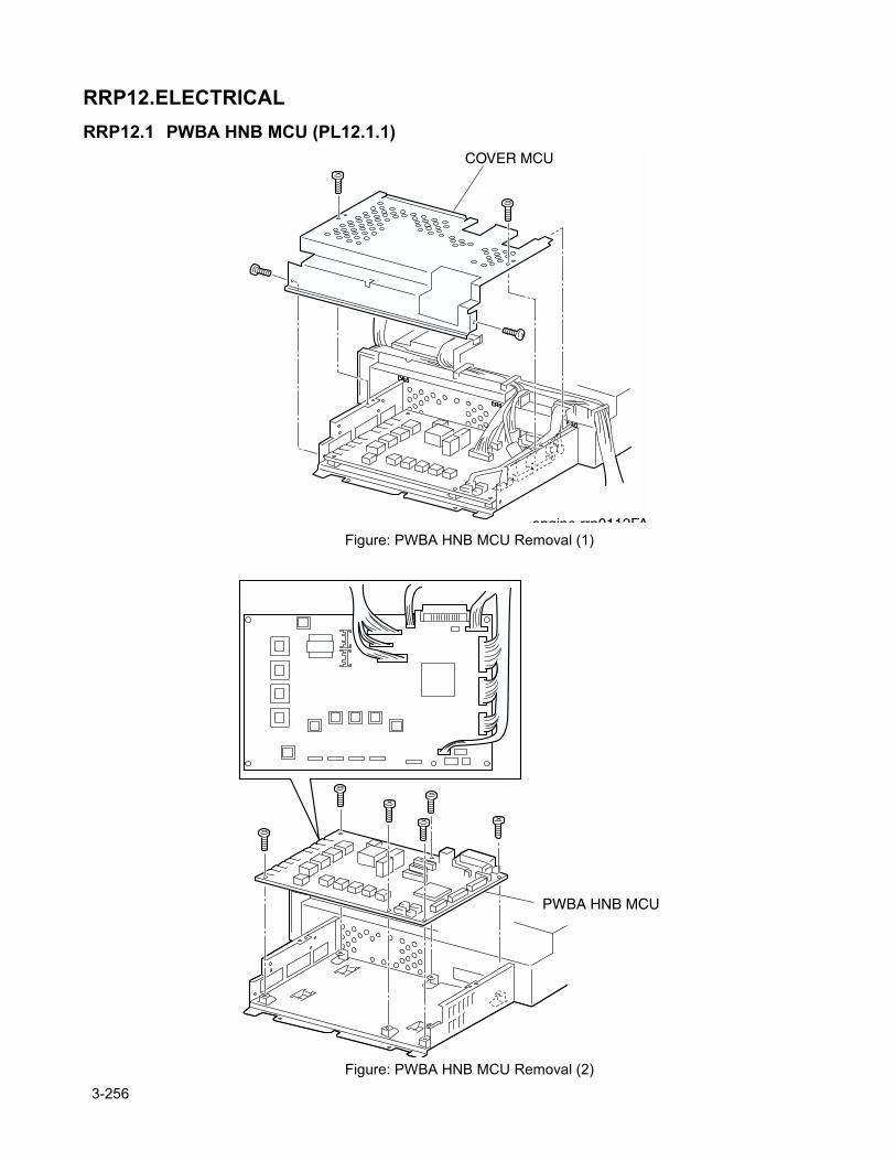
RRP12.ELECTRICALRRP12.1 PWBA HNB MCU (PL12.1.1)
Figure: PWBA HNB MCU Removal (1)
Figure: PWBA HNB MCU Removal (2)
3-256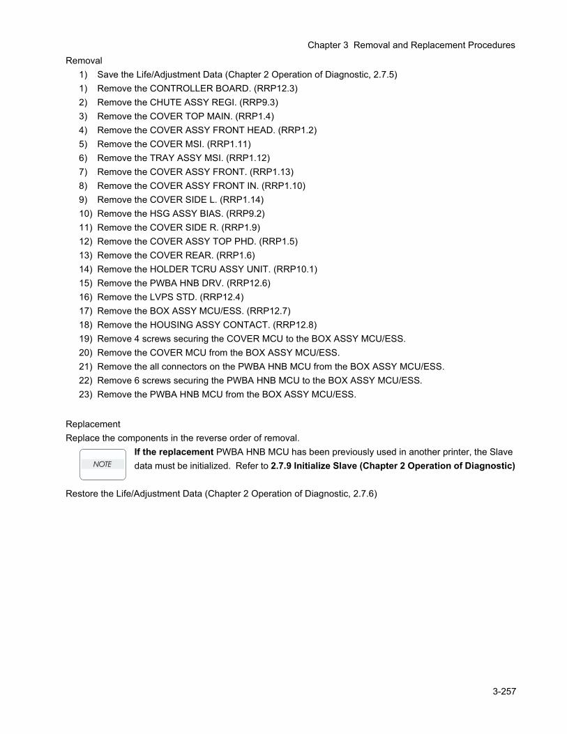
Chapter 3 Removal and Replacement Procedures
Removal1) Save the Life/Adjustment Data (Chapter 2 Operation of Diagnostic, 2.7.5)1) Remove the CONTROLLER BOARD. (RRP12.3)2) Remove the CHUTE ASSY REGI. (RRP9.3)3) Remove the COVER TOP MAIN. (RRP1.4)4) Remove the COVER ASSY FRONT HEAD. (RRP1.2)5) Remove the COVER MSI. (RRP1.11)6) Remove the TRAY ASSY MSI. (RRP1.12)7) Remove the COVER ASSY FRONT. (RRP1.13)8) Remove the COVER ASSY FRONT IN. (RRP1.10)9) Remove the COVER SIDE L. (RRP1.14)10) Remove the HSG ASSY BIAS. (RRP9.2)11) Remove the COVER SIDE R. (RRP1.9)12) Remove the COVER ASSY TOP PHD. (RRP1.5)13) Remove the COVER REAR. (RRP1.6)14) Remove the HOLDER TCRU ASSY UNIT. (RRP10.1)15) Remove the PWBA HNB DRV. (RRP12.6)16) Remove the LVPS STD. (RRP12.4)17) Remove the BOX ASSY MCU/ESS. (RRP12.7)18) Remove the HOUSING ASSY CONTACT. (RRP12.8)19) Remove 4 screws securing the COVER MCU to the BOX ASSY MCU/ESS.20) Remove the COVER MCU from the BOX ASSY MCU/ESS.21) Remove the all connectors on the PWBA HNB MCU from the BOX ASSY MCU/ESS.22) Remove 6 screws securing the PWBA HNB MCU to the BOX ASSY MCU/ESS.23) Remove the PWBA HNB MCU from the BOX ASSY MCU/ESS.
ReplacementReplace the components in the reverse order of removal.
If the replacement PWBA HNB MCU has been previously used in another printer, the Slave data must be initialized. Refer to 2.7.9 Initialize Slave (Chapter 2 Operation of Diagnostic)
Restore the Life/Adjustment Data (Chapter 2 Operation of Diagnostic, 2.7.6)
3-257
RRP12.2 FAN REAR (PL12.1.2)
Figure: FAN REAR RemovalRemoval
1) Remove the COVER TOP MAIN. (RRP1.4)2) Remove the COVER ASSY FRONT HEAD. (RRP1.2)3) Remove the COVER MSI. (RRP1.11)4) Remove the TRAY ASSY MSI. (RRP1.12)5) Remove the COVER ASSY FRONT. (RRP1.13)6) Remove the COVER ASSY FRONT IN. (RRP1.10)7) Remove the COVER SIDE L. (RRP1.14)8) Remove the COVER SIDE R. (RRP1.9)9) Remove the COVER REAR. (RRP1.6)10) Remove the connector (P/J166) on the LVPS from the right side surface of the printer.11) Shift the harness (P/J166) of the FAN REAR from 3 hooks of the HOLDER TCRU ASSY of the printer.12) Remove 2 screws securing the FAN REAR from the printer.13) Remove the FAN REAR from the printer.
ReplacementReplace the components in the reverse order of removal.
3-258
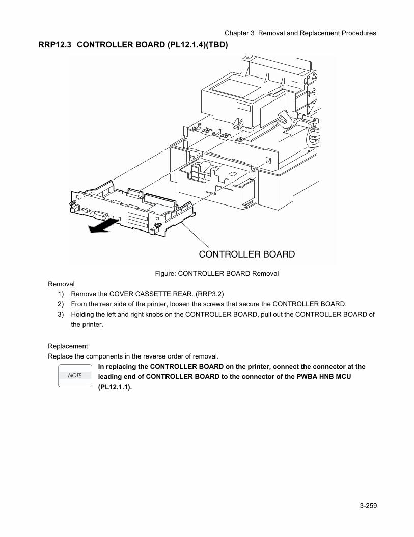
Chapter 3 Removal and Replacement Procedures
RRP12.3 CONTROLLER BOARD (PL12.1.4)(TBD)
Figure: CONTROLLER BOARD RemovalRemoval
1) Remove the COVER CASSETTE REAR. (RRP3.2)2) From the rear side of the printer, loosen the screws that secure the CONTROLLER BOARD.3) Holding the left and right knobs on the CONTROLLER BOARD, pull out the CONTROLLER BOARD of
the printer.
ReplacementReplace the components in the reverse order of removal.
In replacing the CONTROLLER BOARD on the printer, connect the connector at the leading end of CONTROLLER BOARD to the connector of the PWBA HNB MCU (PL12.1.1).
3-259
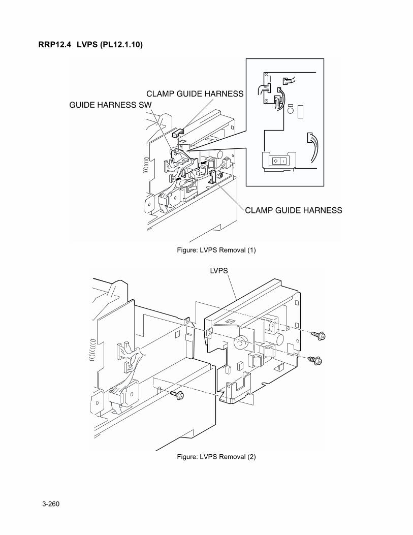
RRP12.4 LVPS (PL12.1.10)
Figure: LVPS Removal (1)
Figure: LVPS Removal (2)
3-260
Chapter 3 Removal and Replacement Procedures
Removal1) Remove the FUSER ASSY. (RRP8.1)2) Remove the CHUTE ASSY REGI. (RRP9.3)3) Remove the COVER TOP MAIN. (RRP1.4)4) Remove the COVER ASSY FRONT HEAD. (RRP1.2)5) Remove the COVER MSI. (RRP1.11)6) Remove the TRAY ASSY MSI. (RRP1.12)7) Remove the COVER ASSY FRONT. (RRP1.13)8) Remove the COVER ASSY FRONT IN. (RRP1.10)9) Remove the COVER SIDE L. (RRP1.14)10) Remove the HSG ASSY BIAS. (RRP9.2)11) Remove the COVER SIDE R. (RRP1.9)12) Remove the COVER ASSY TOP PHD. (RRP1.5)13) Remove the COVER REAR. (RRP1.6)14) Remove the HOLDER TCRU ASSY UNIT. (RRP10.1)15) Remove the PWBA HNB DRV. (RRP12.6)16) Remove the CLAMP GUIDE HARNESS (PL12.1.3) at 2 positions secured on the GUIDE HARNESS
SW of the LVPS STD.17) Shift the harness from the GUIDE HARNESS SW.18) Release the hooks at 2 positions securing the GUIDE HARNESS SW to the switch bracket on the
LVPS STD.19) Remove the GUIDE HARNESS ASSY from the LVPS STD.20) Remove the HARNESS ASSY AC SW. (RRP12.5)21) Remove the connector (P/J162), (P/J163), (P/J164), (P/J165) and (P/J167) on the LVPS STD.22) Remove 3 screws securing the LVPS STD to the printer.23) Remove the LVPS STD from the printer.
ReplacementReplace the components in the reverse order of removal.
3-261
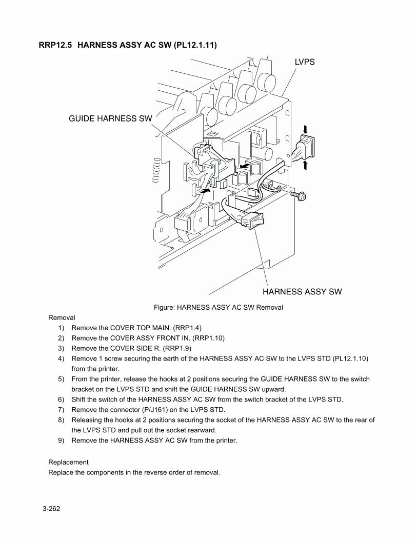
RRP12.5 HARNESS ASSY AC SW (PL12.1.11)
Figure: HARNESS ASSY AC SW RemovalRemoval
1) Remove the COVER TOP MAIN. (RRP1.4)2) Remove the COVER ASSY FRONT IN. (RRP1.10)3) Remove the COVER SIDE R. (RRP1.9)4) Remove 1 screw securing the earth of the HARNESS ASSY AC SW to the LVPS STD (PL12.1.10)
from the printer.5) From the printer, release the hooks at 2 positions securing the GUIDE HARNESS SW to the switch
bracket on the LVPS STD and shift the GUIDE HARNESS SW upward.6) Shift the switch of the HARNESS ASSY AC SW from the switch bracket of the LVPS STD.7) Remove the connector (P/J161) on the LVPS STD.8) Releasing the hooks at 2 positions securing the socket of the HARNESS ASSY AC SW to the rear of
the LVPS STD and pull out the socket rearward.9) Remove the HARNESS ASSY AC SW from the printer.
ReplacementReplace the components in the reverse order of removal.
3-262
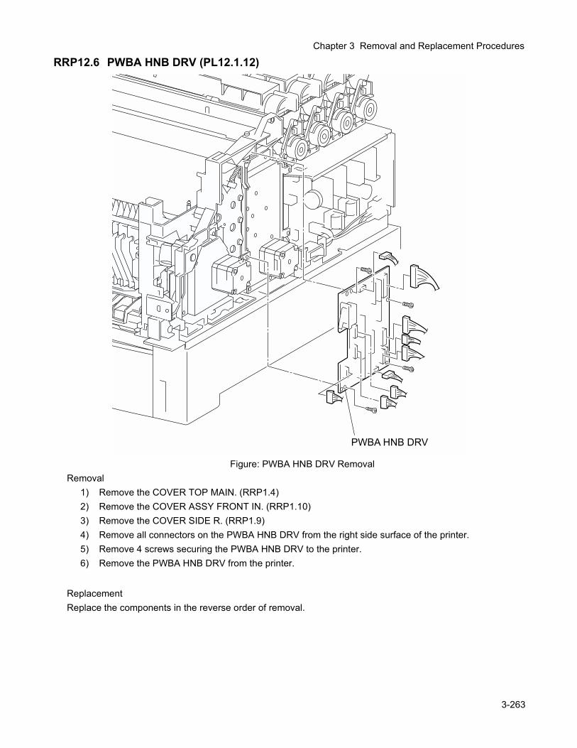
Chapter 3 Removal and Replacement Procedures
RRP12.6 PWBA HNB DRV (PL12.1.12)
Figure: PWBA HNB DRV RemovalRemoval
1) Remove the COVER TOP MAIN. (RRP1.4)2) Remove the COVER ASSY FRONT IN. (RRP1.10)3) Remove the COVER SIDE R. (RRP1.9)4) Remove all connectors on the PWBA HNB DRV from the right side surface of the printer.5) Remove 4 screws securing the PWBA HNB DRV to the printer.6) Remove the PWBA HNB DRV from the printer.
ReplacementReplace the components in the reverse order of removal.
3-263
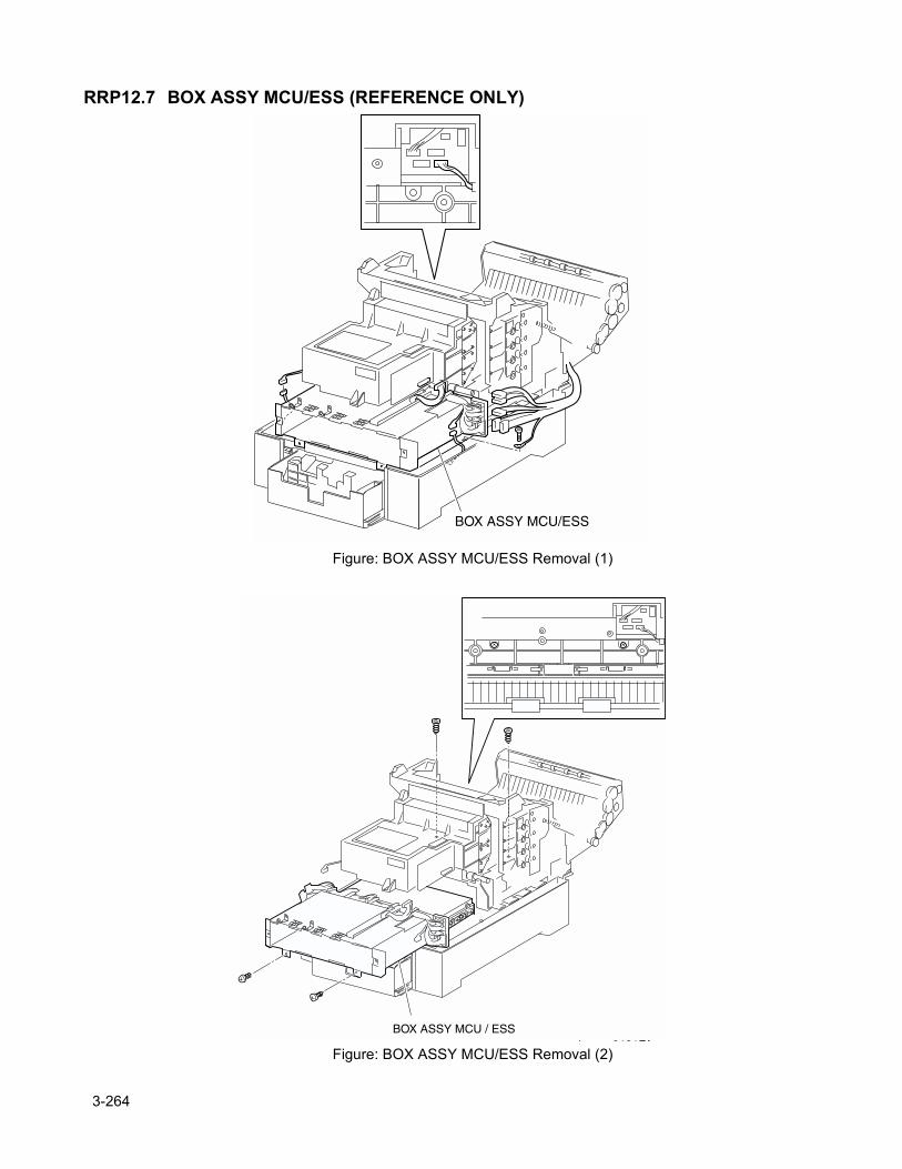
RRP12.7 BOX ASSY MCU/ESS (REFERENCE ONLY)
Figure: BOX ASSY MCU/ESS Removal (1)
Figure: BOX ASSY MCU/ESS Removal (2)
3-264
Chapter 3 Removal and Replacement Procedures
Removal1) Remove the CONTROLLER BOARD. (RRP12.3)2) Remove the CHUTE ASSY REGI. (RRP9.3)3) Remove the COVER TOP MAIN. (RRP1.4)4) Remove the COVER ASSY FRONT HEAD. (RRP1.2)5) Remove the COVER MSI. (RRP1.11)6) Remove the TRAY ASSY MSI. (RRP1.12)7) Remove the COVER ASSY FRONT. (RRP1.13)8) Remove the COVER ASSY FRONT IN. (RRP1.10)9) Remove the COVER SIDE L. (RRP1.14)10) Remove the HSG ASSY BIAS. (RRP9.2)11) Remove the COVER SIDE R. (RRP1.9)12) Remove the COVER ASSY TOP PHD. (RRP1.5)13) Remove the COVER REAR. (RRP1.6)14) Remove the HOLDER TCRU ASSY UNIT. (RRP10.1)15) Remove the PWBA HNB DRV. (RRP12.6)16) Remove the LVPS STD. (RRP12.4)17) Remove the connector (P/J210) connecting the printer and FEEDER from the right side surface of the
printer.18) Remove the connector (P/J151) on the ROS ASSY (PL9.1.1) from the right side surface of the printer.19) Remove the connector (P/J24) connecting the FEEDER to the printer from the left side surface of the
printer.20) Remove the connector (P/J141), connector (P/J1361), connector (P/J138), connector (P/J221) and
connector (P/J139) on the connector bracket from the left side surface of the printer.21) Remove the connector (P/J19) on the PWBA HNB MCU (PL12.1.1) from the inside of the printer.22) Remove 1 screw securing the earth cable from the left side surface of the printer.23) Remove 4 screws securing the BOX ASSY MCU/ESS to the printer.24) Pull out the BOX ASSY MCU/ESS rearward from the printer and remove.
ReplacementReplace the components in the reverse order of removal.
3-265
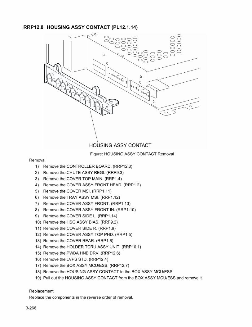
RRP12.8 HOUSING ASSY CONTACT (PL12.1.14)
Figure: HOUSING ASSY CONTACT RemovalRemoval
1) Remove the CONTROLLER BOARD. (RRP12.3)2) Remove the CHUTE ASSY REGI. (RRP9.3)3) Remove the COVER TOP MAIN. (RRP1.4)4) Remove the COVER ASSY FRONT HEAD. (RRP1.2)5) Remove the COVER MSI. (RRP1.11)6) Remove the TRAY ASSY MSI. (RRP1.12)7) Remove the COVER ASSY FRONT. (RRP1.13)8) Remove the COVER ASSY FRONT IN. (RRP1.10)9) Remove the COVER SIDE L. (RRP1.14)10) Remove the HSG ASSY BIAS. (RRP9.2)11) Remove the COVER SIDE R. (RRP1.9)12) Remove the COVER ASSY TOP PHD. (RRP1.5)13) Remove the COVER REAR. (RRP1.6)14) Remove the HOLDER TCRU ASSY UNIT. (RRP10.1)15) Remove the PWBA HNB DRV. (RRP12.6)16) Remove the LVPS STD. (RRP12.4)17) Remove the BOX ASSY MCU/ESS. (RRP12.7)18) Remove the HOUSING ASSY CONTACT to the BOX ASSY MCU/ESS.19) Pull out the HOUSING ASSY CONTACT from the BOX ASSY MCU/ESS and remove it.
ReplacementReplace the components in the reverse order of removal.
3-266

Chapter 3 Removal and Replacement Procedures
3-267

3-268

Chapter 4 Plug/Jack (P/J) Connector Locations

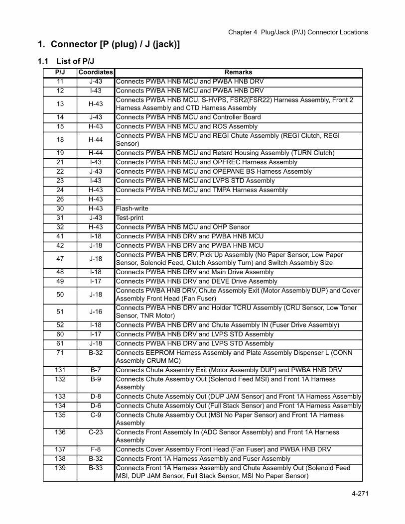
Chapter 4 Plug/Jack (P/J) Connector Locations
1. Connector [P (plug) / J (jack)]
1.1 List of P/JP/J Coordiates Remarks11 J-43 Connects PWBA HNB MCU and PWBA HNB DRV12 I-43 Connects PWBA HNB MCU and PWBA HNB DRV
13 H-43 Connects PWBA HNB MCU, S-HVPS, FSR2(FSR22) Harness Assembly, Front 2 Harness Assembly and CTD Harness Assembly
14 J-43 Connects PWBA HNB MCU and Controller Board15 H-43 Connects PWBA HNB MCU and ROS Assembly
18 H-44 Connects PWBA HNB MCU and REGI Chute Assembly (REGI Clutch, REGI Sensor)
19 H-44 Connects PWBA HNB MCU and Retard Housing Assembly (TURN Clutch)21 I-43 Connects PWBA HNB MCU and OPFREC Harness Assembly22 J-43 Connects PWBA HNB MCU and OPEPANE BS Harness Assembly23 I-43 Connects PWBA HNB MCU and LVPS STD Assembly24 H-43 Connects PWBA HNB MCU and TMPA Harness Assembly26 H-43 --30 H-43 Flash-write31 J-43 Test-print32 H-43 Connects PWBA HNB MCU and OHP Sensor41 I-18 Connects PWBA HNB DRV and PWBA HNB MCU42 J-18 Connects PWBA HNB DRV and PWBA HNB MCU
47 J-18 Connects PWBA HNB DRV, Pick Up Assembly (No Paper Sensor, Low Paper Sensor, Solenoid Feed, Clutch Assembly Turn) and Switch Assembly Size
48 I-18 Connects PWBA HNB DRV and Main Drive Assembly49 I-17 Connects PWBA HNB DRV and DEVE Drive Assembly
50 J-18 Connects PWBA HNB DRV, Chute Assembly Exit (Motor Assembly DUP) and Cover Assembly Front Head (Fan Fuser)
51 J-16 Connects PWBA HNB DRV and Holder TCRU Assembly (CRU Sensor, Low Toner Sensor, TNR Motor)
52 I-18 Connects PWBA HNB DRV and Chute Assembly IN (Fuser Drive Assembly)60 I-17 Connects PWBA HNB DRV and LVPS STD Assembly61 J-18 Connects PWBA HNB DRV and LVPS STD Assembly71 B-32 Connects EEPROM Harness Assembly and Plate Assembly Dispenser L (CONN
Assembly CRUM MC)131 B-7 Connects Chute Assembly Exit (Motor Assembly DUP) and PWBA HNB DRV132 B-9 Connects Chute Assembly Out (Solenoid Feed MSI) and Front 1A Harness
Assembly133 D-8 Connects Chute Assembly Out (DUP JAM Sensor) and Front 1A Harness Assembly134 D-6 Connects Chute Assembly Out (Full Stack Sensor) and Front 1A Harness Assembly135 C-9 Connects Chute Assembly Out (MSI No Paper Sensor) and Front 1A Harness
Assembly136 C-23 Connects Front Assembly In (ADC Sensor Assembly) and Front 1A Harness
Assembly137 F-8 Connects Cover Assembly Front Head (Fan Fuser) and PWBA HNB DRV138 B-32 Connects Front 1A Harness Assembly and Fuser Assembly139 B-33 Connects Front 1A Harness Assembly and Chute Assembly Out (Solenoid Feed
MSI, DUP JAM Sensor, Full Stack Sensor, MSI No Paper Sensor)
4-271
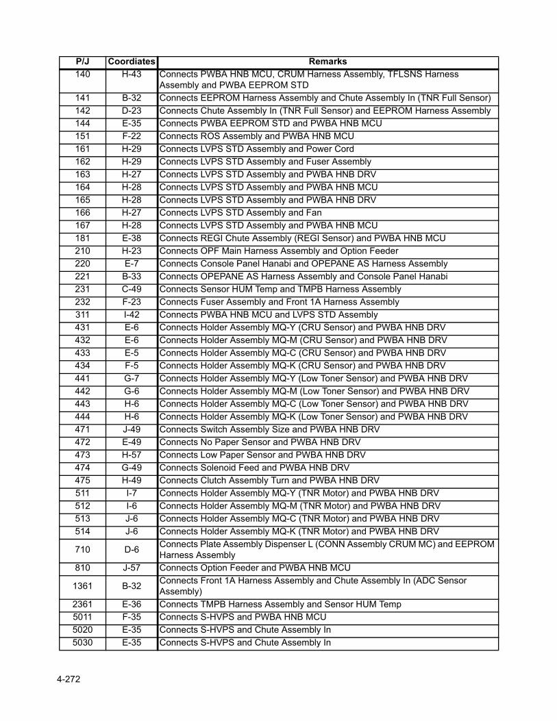
140 H-43 Connects PWBA HNB MCU, CRUM Harness Assembly, TFLSNS Harness Assembly and PWBA EEPROM STD
141 B-32 Connects EEPROM Harness Assembly and Chute Assembly In (TNR Full Sensor)142 D-23 Connects Chute Assembly In (TNR Full Sensor) and EEPROM Harness Assembly144 E-35 Connects PWBA EEPROM STD and PWBA HNB MCU151 F-22 Connects ROS Assembly and PWBA HNB MCU161 H-29 Connects LVPS STD Assembly and Power Cord162 H-29 Connects LVPS STD Assembly and Fuser Assembly163 H-27 Connects LVPS STD Assembly and PWBA HNB DRV164 H-28 Connects LVPS STD Assembly and PWBA HNB MCU165 H-28 Connects LVPS STD Assembly and PWBA HNB DRV166 H-27 Connects LVPS STD Assembly and Fan167 H-28 Connects LVPS STD Assembly and PWBA HNB MCU181 E-38 Connects REGI Chute Assembly (REGI Sensor) and PWBA HNB MCU210 H-23 Connects OPF Main Harness Assembly and Option Feeder220 E-7 Connects Console Panel Hanabi and OPEPANE AS Harness Assembly221 B-33 Connects OPEPANE AS Harness Assembly and Console Panel Hanabi231 C-49 Connects Sensor HUM Temp and TMPB Harness Assembly232 F-23 Connects Fuser Assembly and Front 1A Harness Assembly311 I-42 Connects PWBA HNB MCU and LVPS STD Assembly431 E-6 Connects Holder Assembly MQ-Y (CRU Sensor) and PWBA HNB DRV432 E-6 Connects Holder Assembly MQ-M (CRU Sensor) and PWBA HNB DRV433 E-5 Connects Holder Assembly MQ-C (CRU Sensor) and PWBA HNB DRV434 F-5 Connects Holder Assembly MQ-K (CRU Sensor) and PWBA HNB DRV441 G-7 Connects Holder Assembly MQ-Y (Low Toner Sensor) and PWBA HNB DRV442 G-6 Connects Holder Assembly MQ-M (Low Toner Sensor) and PWBA HNB DRV443 H-6 Connects Holder Assembly MQ-C (Low Toner Sensor) and PWBA HNB DRV444 H-6 Connects Holder Assembly MQ-K (Low Toner Sensor) and PWBA HNB DRV471 J-49 Connects Switch Assembly Size and PWBA HNB DRV472 E-49 Connects No Paper Sensor and PWBA HNB DRV473 H-57 Connects Low Paper Sensor and PWBA HNB DRV474 G-49 Connects Solenoid Feed and PWBA HNB DRV475 H-49 Connects Clutch Assembly Turn and PWBA HNB DRV511 I-7 Connects Holder Assembly MQ-Y (TNR Motor) and PWBA HNB DRV512 I-6 Connects Holder Assembly MQ-M (TNR Motor) and PWBA HNB DRV513 J-6 Connects Holder Assembly MQ-C (TNR Motor) and PWBA HNB DRV514 J-6 Connects Holder Assembly MQ-K (TNR Motor) and PWBA HNB DRV
710 D-6 Connects Plate Assembly Dispenser L (CONN Assembly CRUM MC) and EEPROM Harness Assembly
810 J-57 Connects Option Feeder and PWBA HNB MCU
1361 B-32 Connects Front 1A Harness Assembly and Chute Assembly In (ADC Sensor Assembly)
2361 E-36 Connects TMPB Harness Assembly and Sensor HUM Temp5011 F-35 Connects S-HVPS and PWBA HNB MCU5020 E-35 Connects S-HVPS and Chute Assembly In5030 E-35 Connects S-HVPS and Chute Assembly In
P/J Coordiates Remarks
4-272
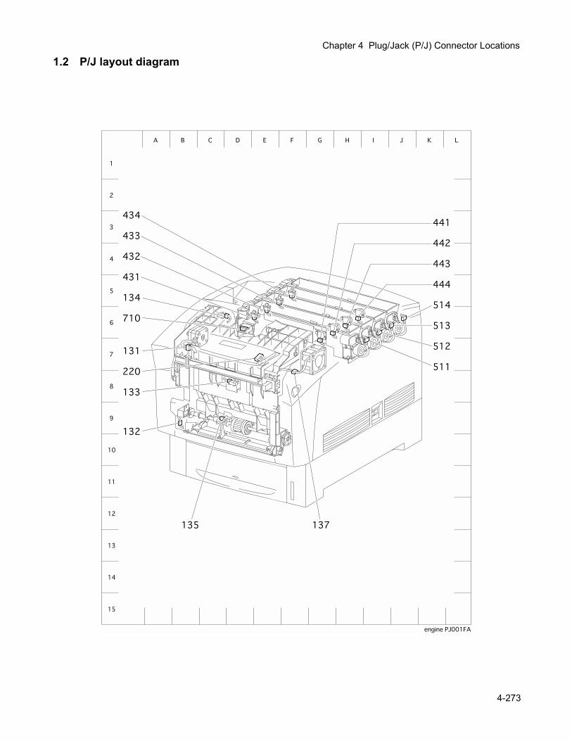
Chapter 4 Plug/Jack (P/J) Connector Locations
1.2 P/J layout diagram
4-273
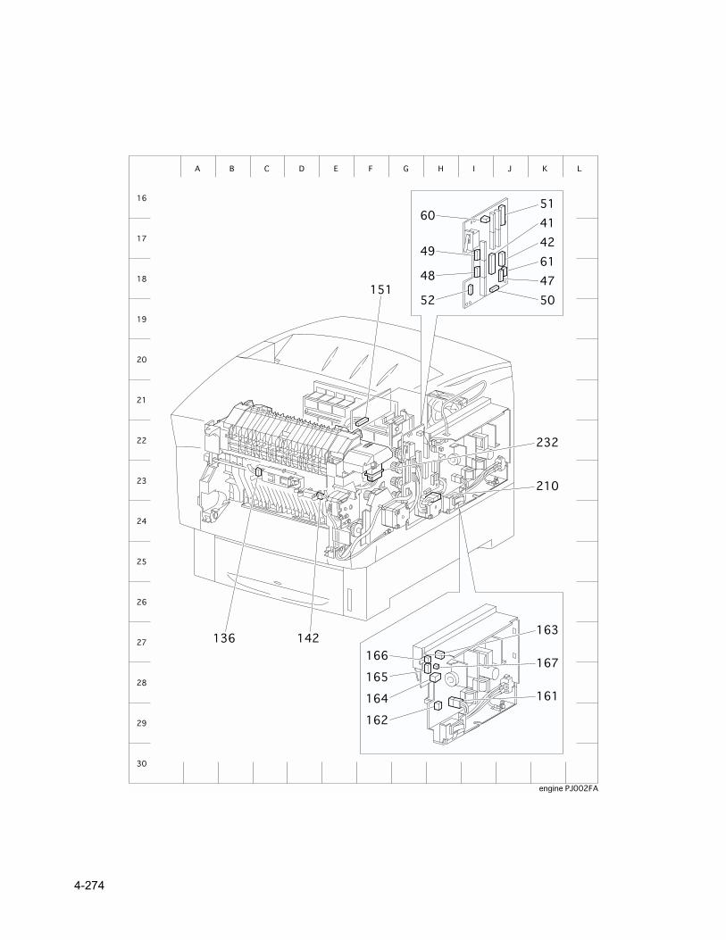
4-274
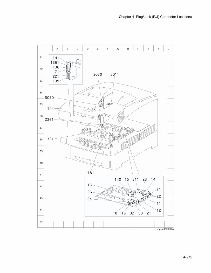
Chapter 4 Plug/Jack (P/J) Connector Locations
4-275
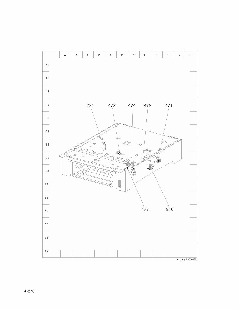
4-276

Chapter 5 Parts List

Chapter 5 Parts List
1. Parts List
1.1 Caution for use of parts list The figures indicating the illustrations are the item No. in the list and present correspondence between
the illustrations and parts. The notation of PL "X.Y.Z" is composed of the plate (PL), item "X.Y", and parts "Z". The alphabet characters in the illustrations represent screws and clips as follows:
"S": screw, "E": E-ring, "KL": KL clip, "C": C-ring, and "N": nut "" mark in the illustrations are attached to items indicating assembly parts in the illustrations. Encircled alphabetical figures in the illustrations indicate interrupted leader lines. Same characters in
the illustrations represent lines to be connected. The mark "(with 2-5)" attached to assembly parts on the illustrations and lists represents that the items
"2, 3, 4, and 5" of that plate are contained and the mark "(with 2-5, PL6.1.1.1) represent that the item "2, 3, 4, and 5" of that plate and the item "1" of the plate "6.1" are contained.
The mark "[Same PLX.Y.Z]" attached to parts in the illustrations and lists resents that the parts is the same as the parts of the item "Z" of the plate "X.Y".
The mark "" attached to the item in the list represents "recommended spare parts" which can be usually supplied. (Supply of other parts shall be examined separately.)
The mark "" attached to parts in the list represents "Note" or "Reference" about that parts is contained in the same page.
"HIGH ASSY" in the list represent the high level assembly parts containing that parts.
For spare parts, refer to the "Spare parts list" which is issued separately.
For the connector (P/J), parts such as harness, wire, etc. in the list, refer to "Chapter 6, Electric wiring"
It should be noted that configuration of parts may be different or some parts are not used depending on specifications of OEM.
5-281
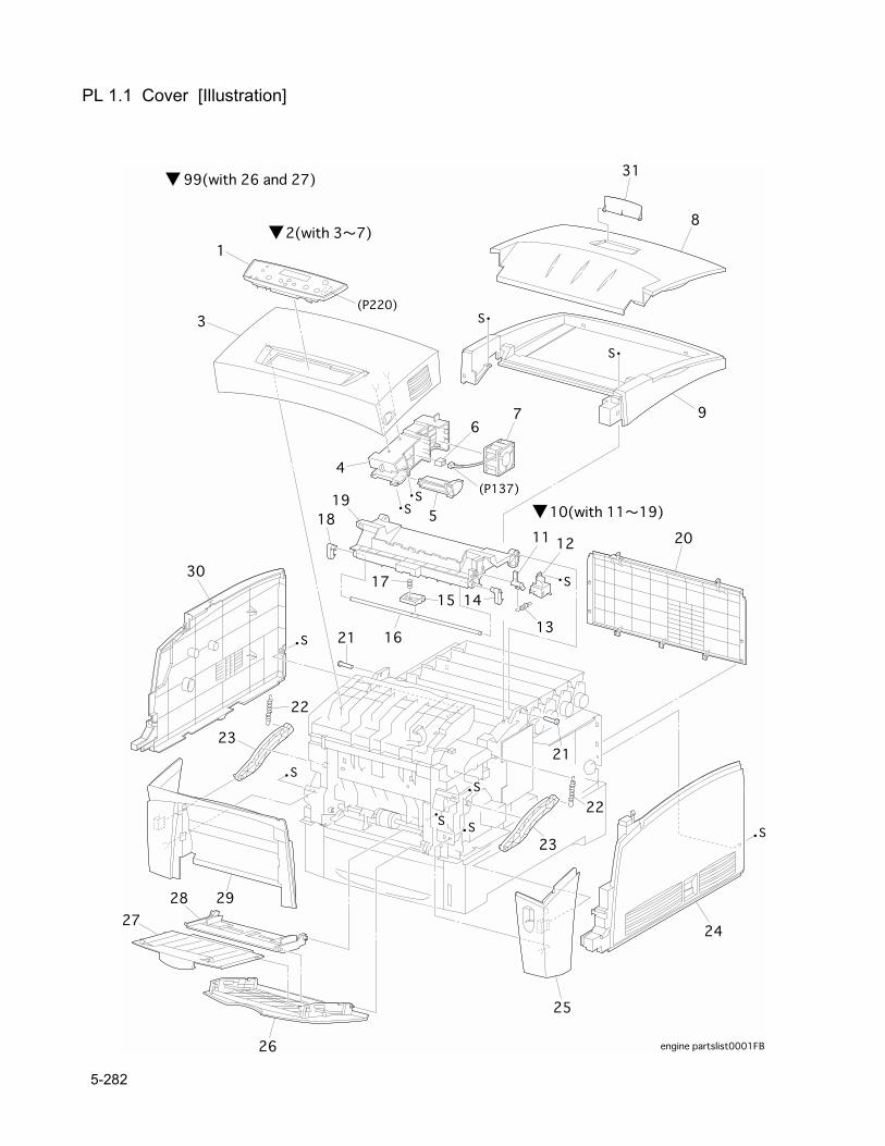
PL 1.1 Cover [Illustration]
5-282
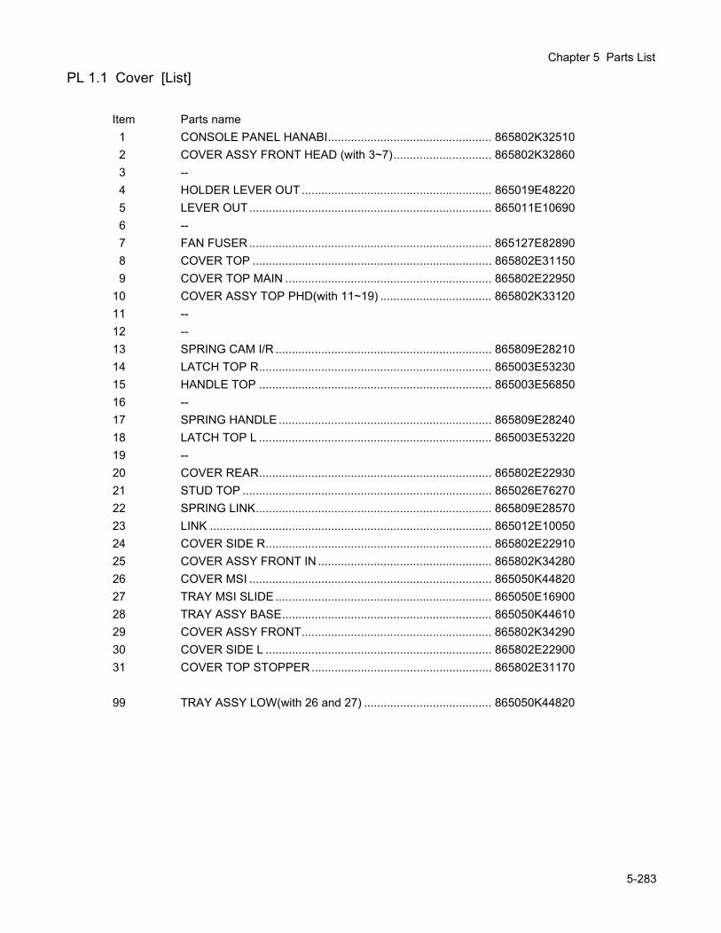
Chapter 5 Parts List
PL 1.1 Cover [List]
Item Parts name1 CONSOLE PANEL HANABI.................................................. 865802K325102 COVER ASSY FRONT HEAD (with 3~7).............................. 865802K328603 --4 HOLDER LEVER OUT.......................................................... 865019E482205 LEVER OUT.......................................................................... 865011E106906 --7 FAN FUSER .......................................................................... 865127E828908 COVER TOP ......................................................................... 865802E311509 COVER TOP MAIN ............................................................... 865802E22950
10 COVER ASSY TOP PHD(with 11~19) .................................. 865802K3312011 --12 --13 SPRING CAM I/R .................................................................. 865809E2821014 LATCH TOP R....................................................................... 865003E5323015 HANDLE TOP ....................................................................... 865003E5685016 --17 SPRING HANDLE ................................................................. 865809E2824018 LATCH TOP L ....................................................................... 865003E5322019 --20 COVER REAR....................................................................... 865802E2293021 STUD TOP ............................................................................ 865026E7627022 SPRING LINK........................................................................ 865809E2857023 LINK ...................................................................................... 865012E1005024 COVER SIDE R..................................................................... 865802E2291025 COVER ASSY FRONT IN ..................................................... 865802K3428026 COVER MSI .......................................................................... 865050K4482027 TRAY MSI SLIDE .................................................................. 865050E1690028 TRAY ASSY BASE................................................................ 865050K4461029 COVER ASSY FRONT.......................................................... 865802K3429030 COVER SIDE L ..................................................................... 865802E2290031 COVER TOP STOPPER ....................................................... 865802E31170
99 TRAY ASSY LOW(with 26 and 27) ....................................... 865050K44820
5-283
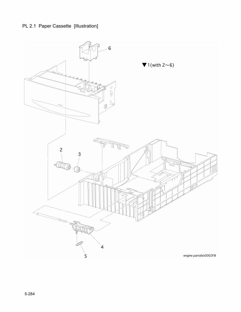
PL 2.1 Paper Cassette [Illustration]
5-284

Chapter 5 Parts List
PL 2.1 Paper Cassette [List]
Item Parts name1 CASSETTE ASSY(with 2~6) ................................................. 865084K030702 ROLL ASSY .......................................................................... 865059K217303 CLUTCH ASSY FRICTION ................................................... 865005E161504 HOLDER RETARD................................................................ 865019E492305 SPRING RETARD................................................................. 865809E301006 A5 BLOCK
5-285
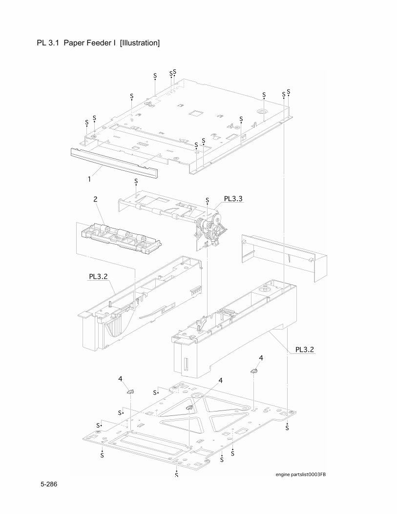
PL 3.1 Paper Feeder I [Illustration]
5-286

Chapter 5 Parts List
PL 3.1 Paper Feeder I [List]
Item Parts name1 COVER FDR FRONT............................................................ 865802E228102 CHUTE ASSY TURN ............................................................ 865054K180003 --4 BLOCK .................................................................................. 865014E421205 --
5-287
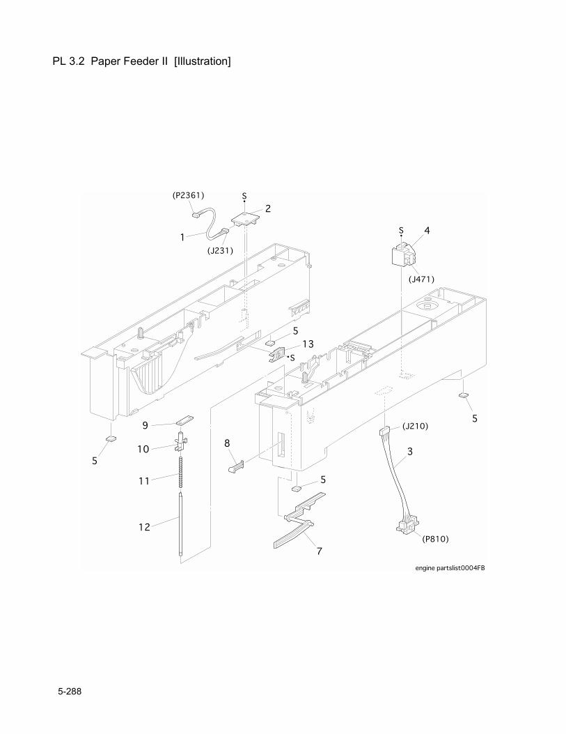
PL 3.2 Paper Feeder II [Illustration]
5-288
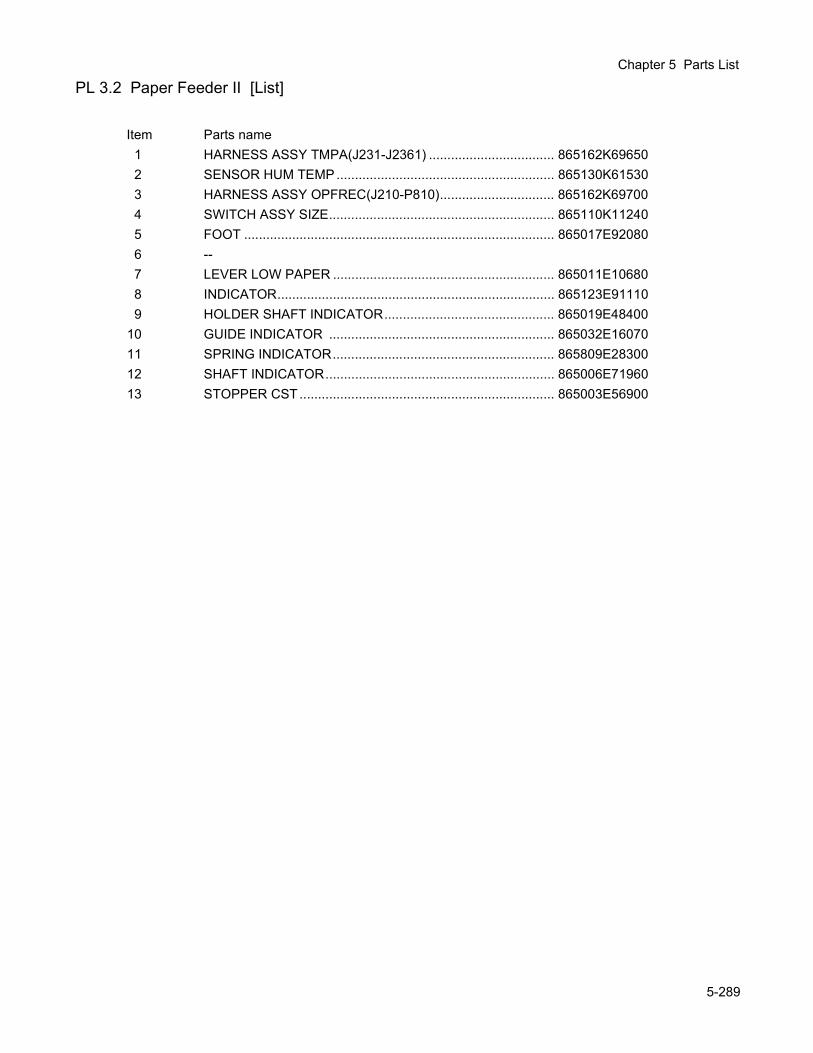
Chapter 5 Parts List
PL 3.2 Paper Feeder II [List]
Item Parts name1 HARNESS ASSY TMPA(J231-J2361) .................................. 865162K696502 SENSOR HUM TEMP ........................................................... 865130K615303 HARNESS ASSY OPFREC(J210-P810)............................... 865162K697004 SWITCH ASSY SIZE............................................................. 865110K112405 FOOT .................................................................................... 865017E920806 --7 LEVER LOW PAPER ............................................................ 865011E106808 INDICATOR........................................................................... 865123E911109 HOLDER SHAFT INDICATOR.............................................. 865019E48400
10 GUIDE INDICATOR ............................................................. 865032E1607011 SPRING INDICATOR............................................................ 865809E2830012 SHAFT INDICATOR.............................................................. 865006E7196013 STOPPER CST ..................................................................... 865003E56900
5-289
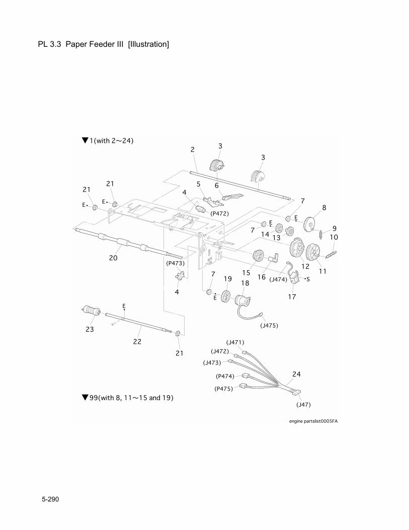
PL 3.3 Paper Feeder III [Illustration]
5-290
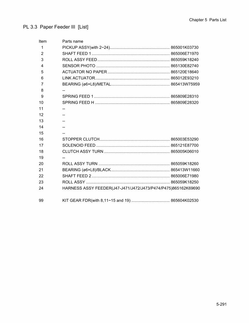
Chapter 5 Parts List
PL 3.3 Paper Feeder III [List]
Item Parts name1 PICKUP ASSY(with 2~24)..................................................... 865001K037302 SHAFT FEED 1 ..................................................................... 865006E719703 ROLL ASSY FEED................................................................ 865059K182404 SENSOR PHOTO ................................................................. 865130E827405 ACTUATOR NO PAPER ....................................................... 865120E186406 LINK ACTUATOR.................................................................. 865012E932107 BEARING (ø6×L8)/METAL.................................................... 865413W759598 --9 SPRING FEED 1 ................................................................... 865809E28310
10 SPRING FEED H .................................................................. 865809E2832011 --12 --13 --14 --15 --16 STOPPER CLUTCH.............................................................. 865003E5329017 SOLENOID FEED ................................................................. 865121E8770018 CLUTCH ASSY TURN .......................................................... 865005K0601019 --20 ROLL ASSY TURN ............................................................... 865059K1826021 BEARING (ø6×L8)/BLACK.................................................... 865413W1166022 SHAFT FEED 2 ..................................................................... 865006E7198023 ROLL ASSY .......................................................................... 865059K1825024 HARNESS ASSY FEEDER(J47-J471/J472/J473/P474/P475)865162K69690
99 KIT GEAR FDR(with 8,11~15 and 19) .................................. 865604K02530
5-291
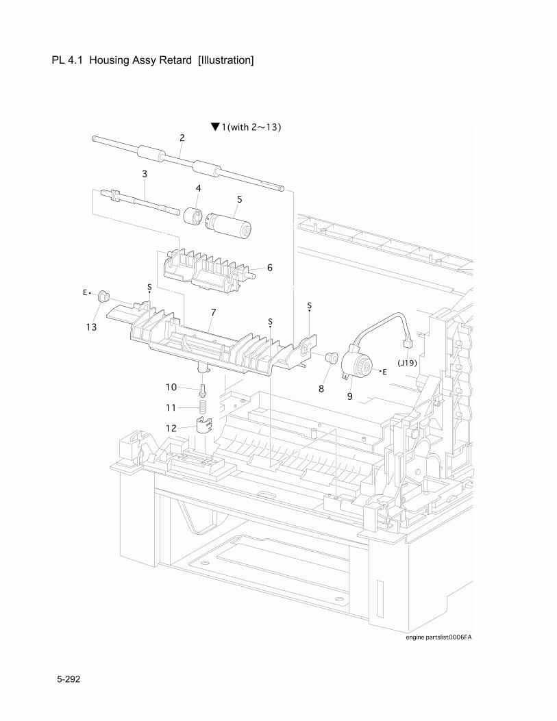
PL 4.1 Housing Assy Retard [Illustration]
5-292
Chapter 5 Parts List
PL 4.1 Housing Assy Retard [List]
Item Parts name1 HOUSING ASSY RETARD(with 2~13) ................................. 865802K248402 ROLL TURN .......................................................................... 865059K199403 --4 CLUTCH ASSY FRICTION ................................................... 865005K824405 ROLL ASSY RETARD........................................................... 865059K199506 --7 --8 BEARING .............................................................................. 865013E180609 CLUTCH TURN..................................................................... 865121E87710
10 STUD RETARD..................................................................... 865026E7772011 SPRING RETARD 370.......................................................... 865809E2867012 CAP RETARD ....................................................................... 865021E9747013 BEARING EARTH................................................................. 865016E19270
5-293
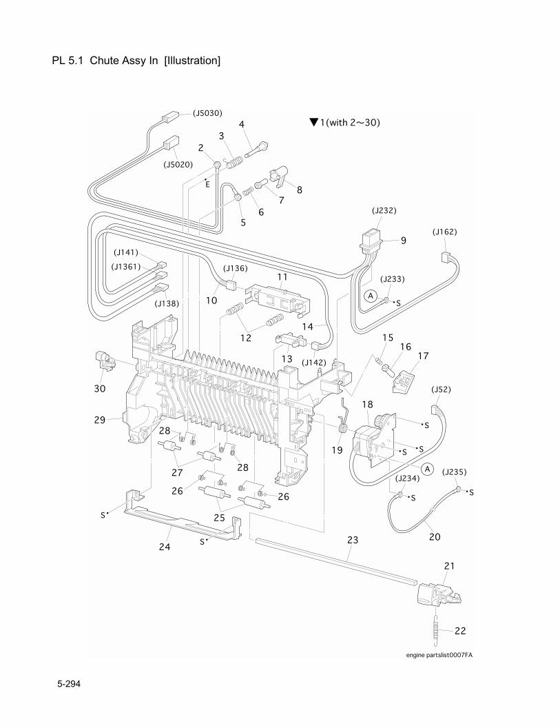
PL 5.1 Chute Assy In [Illustration]
5-294
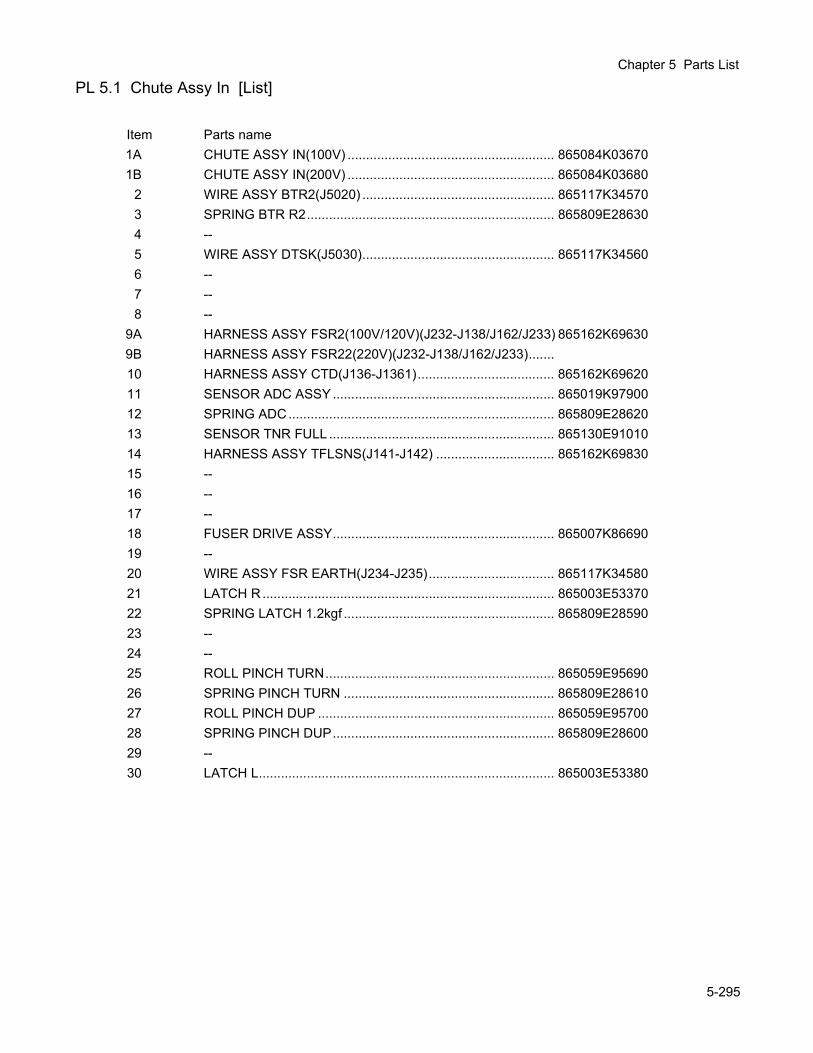
Chapter 5 Parts List
PL 5.1 Chute Assy In [List]
Item Parts name1A CHUTE ASSY IN(100V) ........................................................ 865084K036701B CHUTE ASSY IN(200V) ........................................................ 865084K03680
2 WIRE ASSY BTR2(J5020) .................................................... 865117K345703 SPRING BTR R2................................................................... 865809E286304 --5 WIRE ASSY DTSK(J5030).................................................... 865117K345606 --7 --8 --
9A HARNESS ASSY FSR2(100V/120V)(J232-J138/J162/J233) 865162K696309B HARNESS ASSY FSR22(220V)(J232-J138/J162/J233).......10 HARNESS ASSY CTD(J136-J1361)..................................... 865162K6962011 SENSOR ADC ASSY ............................................................ 865019K9790012 SPRING ADC........................................................................ 865809E2862013 SENSOR TNR FULL ............................................................. 865130E9101014 HARNESS ASSY TFLSNS(J141-J142) ................................ 865162K6983015 --16 --17 --18 FUSER DRIVE ASSY............................................................ 865007K8669019 --20 WIRE ASSY FSR EARTH(J234-J235).................................. 865117K3458021 LATCH R ............................................................................... 865003E5337022 SPRING LATCH 1.2kgf ......................................................... 865809E2859023 --24 --25 ROLL PINCH TURN.............................................................. 865059E9569026 SPRING PINCH TURN ......................................................... 865809E2861027 ROLL PINCH DUP ................................................................ 865059E9570028 SPRING PINCH DUP............................................................ 865809E2860029 --30 LATCH L................................................................................ 865003E53380
5-295
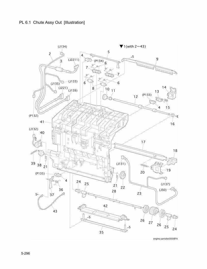
PL 6.1 Chute Assy Out [Illustration]
5-296
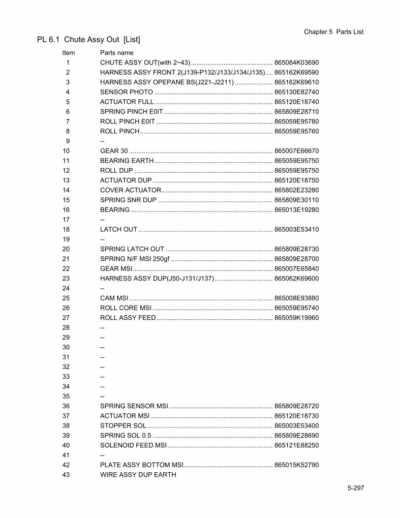
Chapter 5 Parts ListPL 6.1 Chute Assy Out [List]
Item Parts name1 CHUTE ASSY OUT(with 2~43) ............................................. 865084K036902 HARNESS ASSY FRONT 2(J139-P132/J133/J134/J135).... 865162K695903 HARNESS ASSY OPEPANE BS(J221-J2211) ..................... 865162K696104 SENSOR PHOTO ................................................................. 865130E827405 ACTUATOR FULL................................................................. 865120E187406 SPRING PINCH E0IT............................................................ 865809E287107 ROLL PINCH E0IT ................................................................ 865059E957808 ROLL PINCH......................................................................... 865059E957609 --
10 GEAR 30 ............................................................................... 865007E6667011 BEARING EARTH................................................................. 865059E9575012 ROLL DUP ............................................................................ 865059E9575013 ACTUATOR DUP .................................................................. 865120E1875014 COVER ACTUATOR............................................................. 865802E2328015 SPRING SNR DUP ............................................................... 865809E3011016 BEARING .............................................................................. 865013E1928017 --18 LATCH OUT.......................................................................... 865003E5341019 --20 SPRING LATCH OUT ........................................................... 865809E2873021 SPRING N/F MSI 250gf ........................................................ 865809E2870022 GEAR MSI............................................................................. 865007E6584023 HARNESS ASSY DUP(J50-J131/J137)................................ 865062K6960024 --25 CAM MSI ............................................................................... 865008E9388026 ROLL CORE MSI .................................................................. 865059E9574027 ROLL ASSY FEED................................................................ 865059K1996028 --29 --30 --31 --32 --33 --34 --35 --36 SPRING SENSOR MSI ......................................................... 865809E2872037 ACTUATOR MSI ................................................................... 865120E1873038 STOPPER SOL..................................................................... 865003E5340039 SPRING SOL 0.5 .................................................................. 865809E2869040 SOLENOID FEED MSI.......................................................... 865121E8825041 --42 PLATE ASSY BOTTOM MSI................................................. 865015K5279043 WIRE ASSY DUP EARTH
5-297
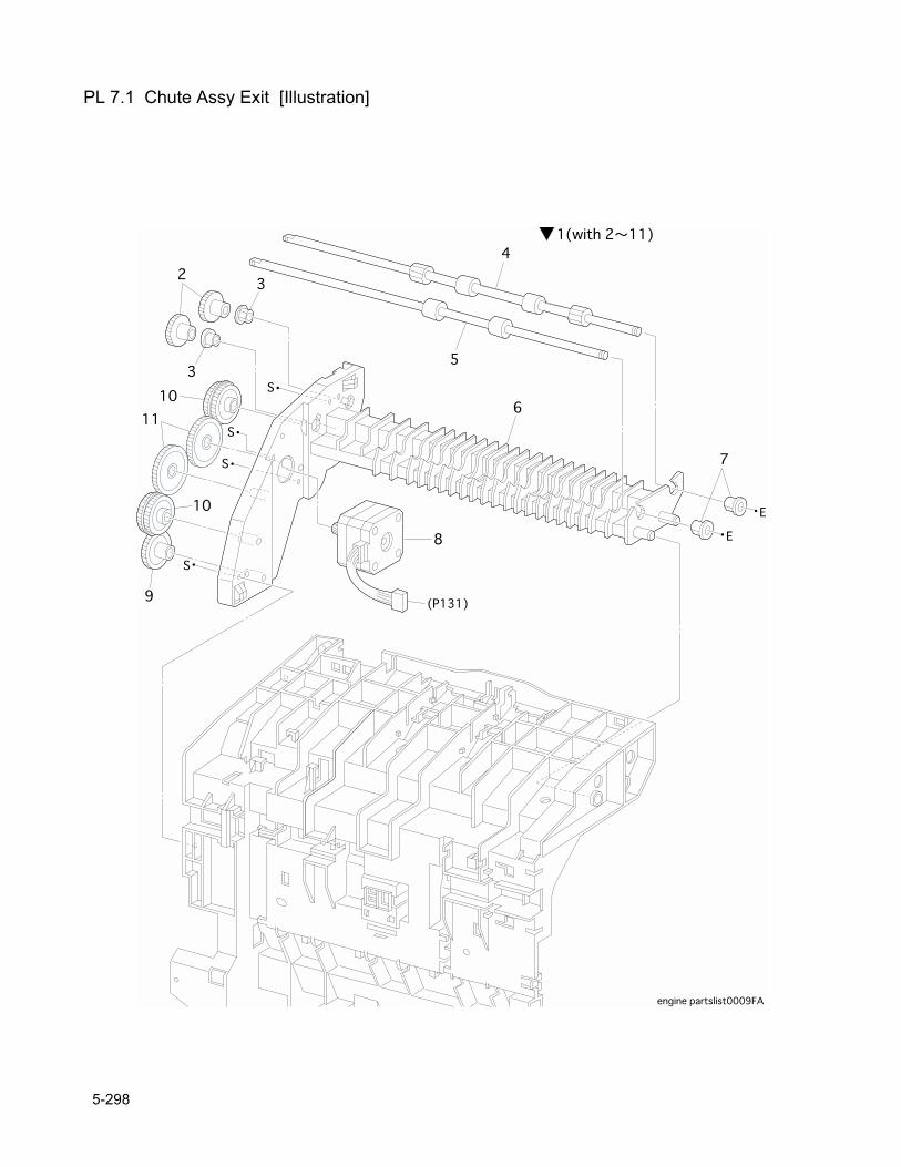
PL 7.1 Chute Assy Exit [Illustration]
5-298
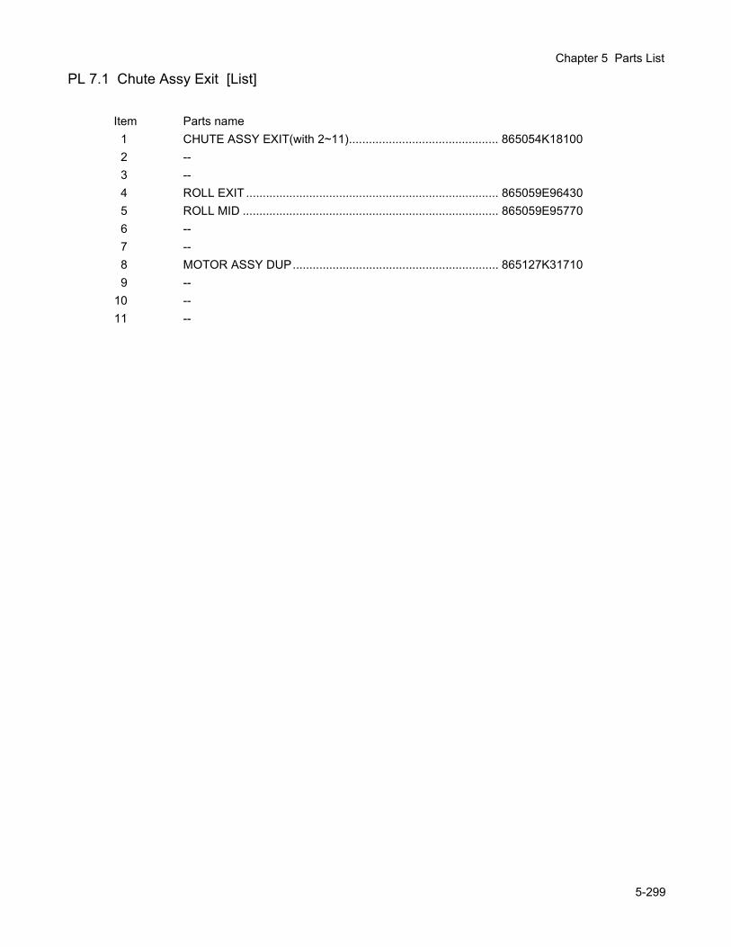
Chapter 5 Parts List
PL 7.1 Chute Assy Exit [List]
Item Parts name1 CHUTE ASSY EXIT(with 2~11)............................................. 865054K181002 --3 --4 ROLL EXIT ............................................................................ 865059E964305 ROLL MID ............................................................................. 865059E957706 --7 --8 MOTOR ASSY DUP.............................................................. 865127K317109 --
10 --11 --
5-299
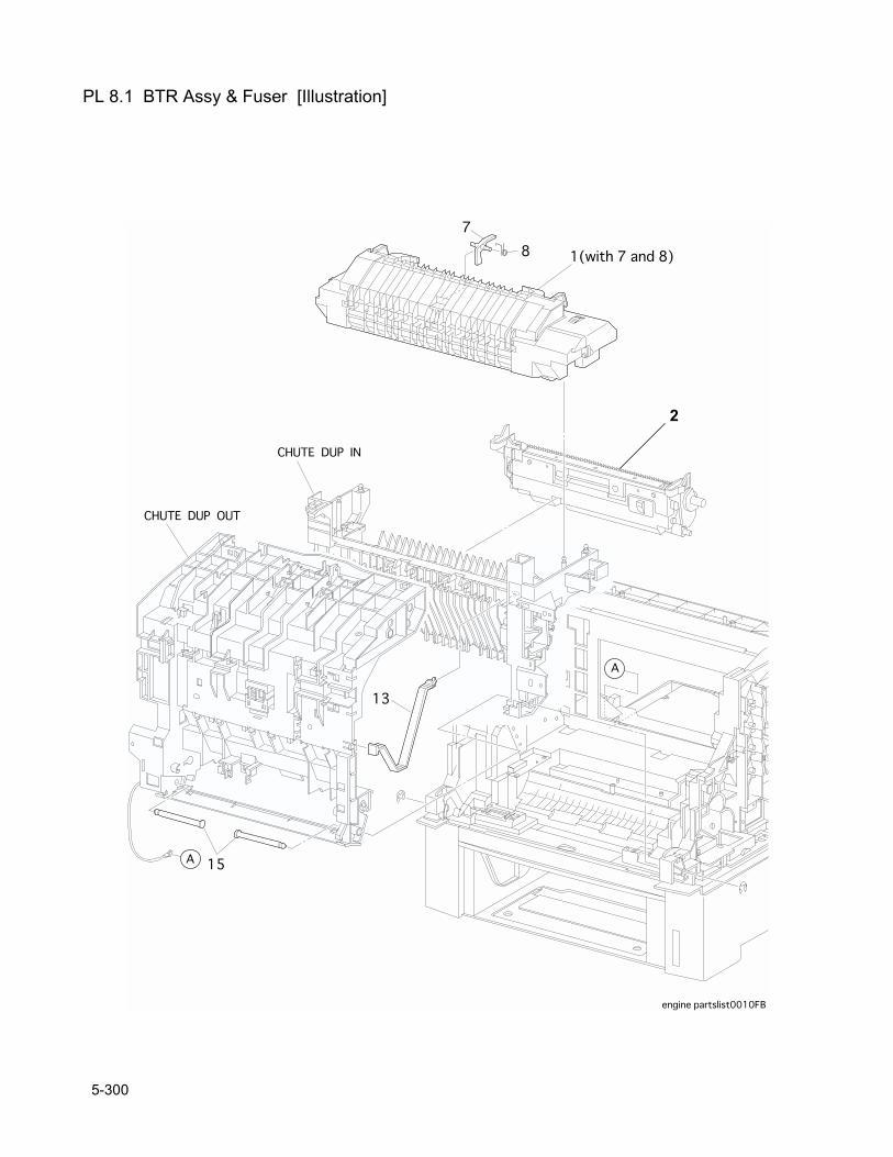
PL 8.1 BTR Assy & Fuser [Illustration]
2
5-300
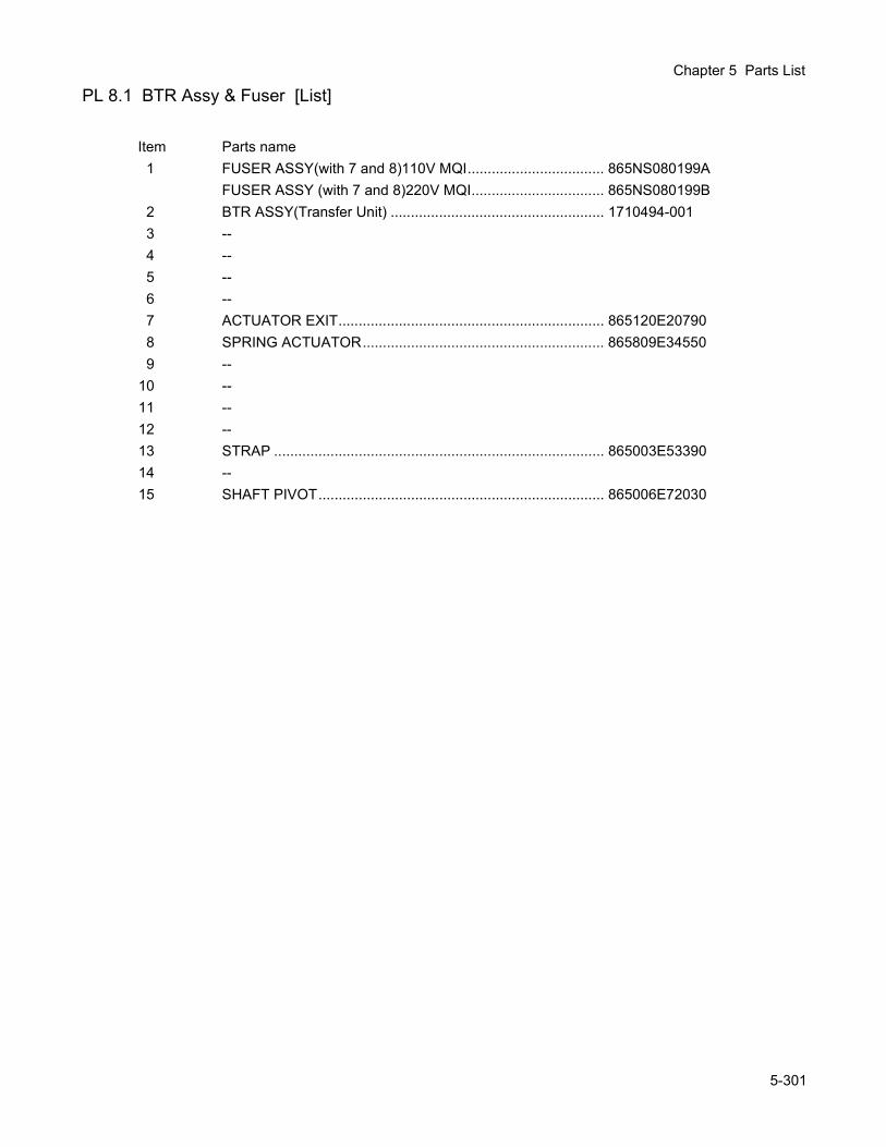
Chapter 5 Parts List
PL 8.1 BTR Assy & Fuser [List]
Item Parts name1 FUSER ASSY(with 7 and 8)110V MQI.................................. 865NS080199A
FUSER ASSY (with 7 and 8)220V MQI................................. 865NS080199B2 BTR ASSY(Transfer Unit) ..................................................... 1710494-0013 --4 --5 --6 --7 ACTUATOR EXIT.................................................................. 865120E207908 SPRING ACTUATOR............................................................ 865809E345509 --
10 --11 --12 --13 STRAP .................................................................................. 865003E5339014 --15 SHAFT PIVOT....................................................................... 865006E72030
5-301
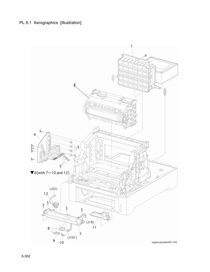
PL 9.1 Xerographics [Illustration]
3
5-302
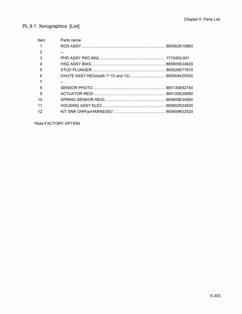
Chapter 5 Parts List
PL 9.1 Xerographics [List]
Item Parts name1 ROS ASSY............................................................................ 865062K108602 --3 PHD ASSY PKG MQI............................................................ 1710493-0014 HSG ASSY BIAS................................................................... 865805K248205 STUD PLUNGER .................................................................. 865026E776706 CHUTE ASSY REGI(with 7~10 and 12)................................ 865054K205307 --8 SENSOR PHOTO ................................................................. 865130E827409 ACTUATOR REGI................................................................. 865120E20680
10 SPRING SENSOR REGI....................................................... 865809E3458011 HOUSING ASSY ELEC......................................................... 865802K2483012 KIT SNR OHP(w/HARNESS)*............................................... 865604K02520
*Note:FACTORY OPTION
5-303
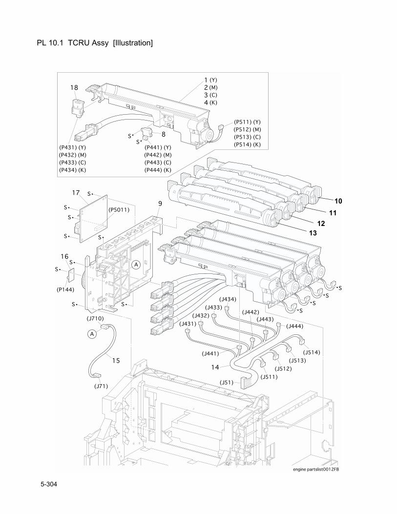
PL 10.1 TCRU Assy [Illustration]
1011
1213
5-304
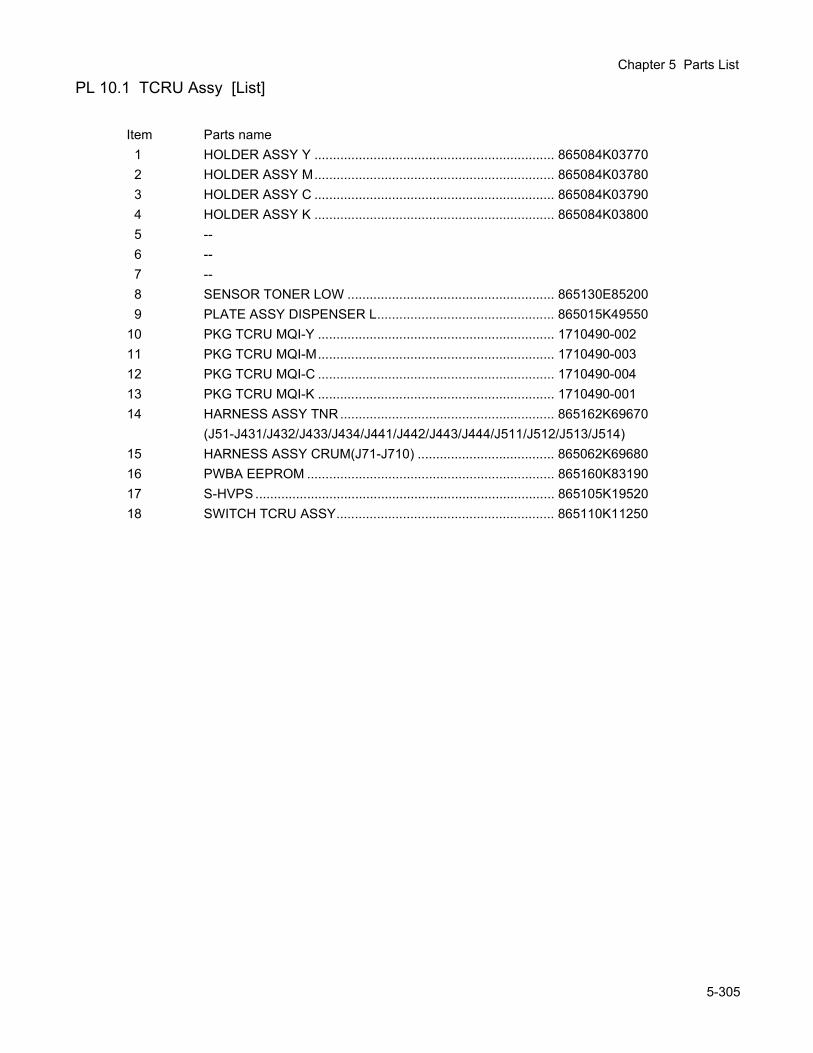
Chapter 5 Parts List
PL 10.1 TCRU Assy [List]
Item Parts name1 HOLDER ASSY Y ................................................................. 865084K037702 HOLDER ASSY M................................................................. 865084K037803 HOLDER ASSY C ................................................................. 865084K037904 HOLDER ASSY K ................................................................. 865084K038005 --6 --7 --8 SENSOR TONER LOW ........................................................ 865130E852009 PLATE ASSY DISPENSER L................................................ 865015K49550
10 PKG TCRU MQI-Y ................................................................ 1710490-00211 PKG TCRU MQI-M................................................................ 1710490-00312 PKG TCRU MQI-C ................................................................ 1710490-00413 PKG TCRU MQI-K ................................................................ 1710490-00114 HARNESS ASSY TNR.......................................................... 865162K69670
(J51-J431/J432/J433/J434/J441/J442/J443/J444/J511/J512/J513/J514)15 HARNESS ASSY CRUM(J71-J710) ..................................... 865062K6968016 PWBA EEPROM ................................................................... 865160K8319017 S-HVPS ................................................................................. 865105K1952018 SWITCH TCRU ASSY........................................................... 865110K11250
5-305
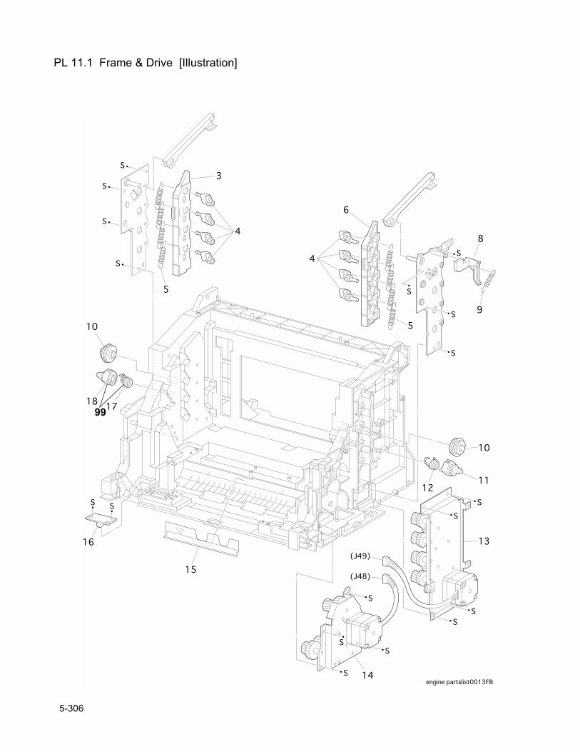
PL 11.1 Frame & Drive [Illustration]
99
5-306
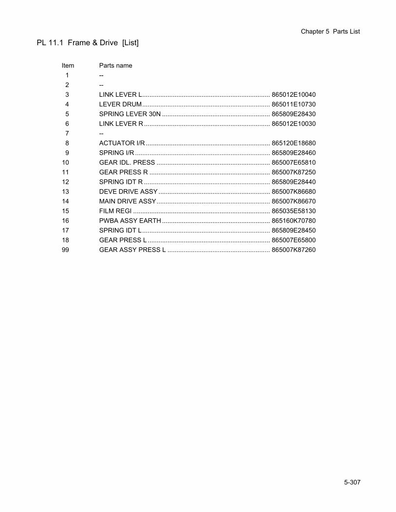
Chapter 5 Parts List
PL 11.1 Frame & Drive [List]
Item Parts name1 --2 --3 LINK LEVER L....................................................................... 865012E100404 LEVER DRUM....................................................................... 865011E107305 SPRING LEVER 30N ............................................................ 865809E284306 LINK LEVER R ...................................................................... 865012E100307 --8 ACTUATOR I/R ..................................................................... 865120E186809 SPRING I/R ........................................................................... 865809E28460
10 GEAR IDL. PRESS ............................................................... 865007E6581011 GEAR PRESS R ................................................................... 865007K8725012 SPRING IDT R ...................................................................... 865809E2844013 DEVE DRIVE ASSY .............................................................. 865007K8668014 MAIN DRIVE ASSY............................................................... 865007K8667015 FILM REGI ............................................................................ 865035E5813016 PWBA ASSY EARTH ............................................................ 865160K7078017 SPRING IDT L....................................................................... 865809E2845018 GEAR PRESS L .................................................................... 865007E6580099 GEAR ASSY PRESS L ......................................................... 865007K87260
5-307
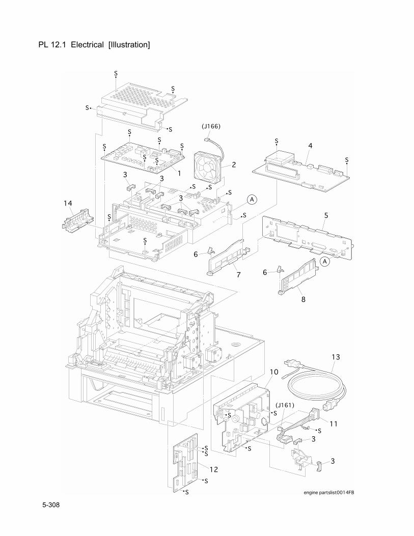
PL 12.1 Electrical [Illustration]
5-308
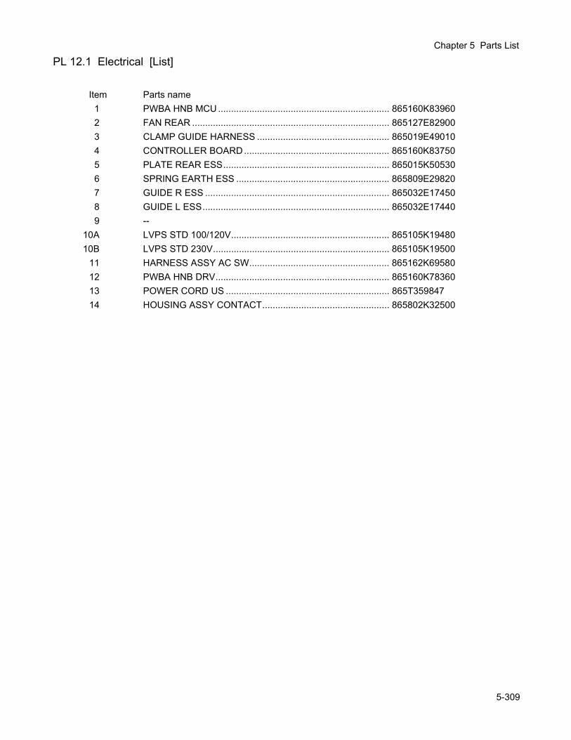
Chapter 5 Parts List
PL 12.1 Electrical [List]
Item Parts name1 PWBA HNB MCU .................................................................. 865160K839602 FAN REAR ............................................................................ 865127E829003 CLAMP GUIDE HARNESS ................................................... 865019E490104 CONTROLLER BOARD........................................................ 865160K837505 PLATE REAR ESS................................................................ 865015K505306 SPRING EARTH ESS ........................................................... 865809E298207 GUIDE R ESS ....................................................................... 865032E174508 GUIDE L ESS........................................................................ 865032E174409 --
10A LVPS STD 100/120V............................................................. 865105K1948010B LVPS STD 230V.................................................................... 865105K19500
11 HARNESS ASSY AC SW...................................................... 865162K6958012 PWBA HNB DRV................................................................... 865160K7836013 POWER CORD US ............................................................... 865T35984714 HOUSING ASSY CONTACT................................................. 865802K32500
5-309
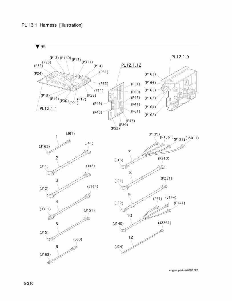
PL 13.1 Harness [Illustration]
5-310
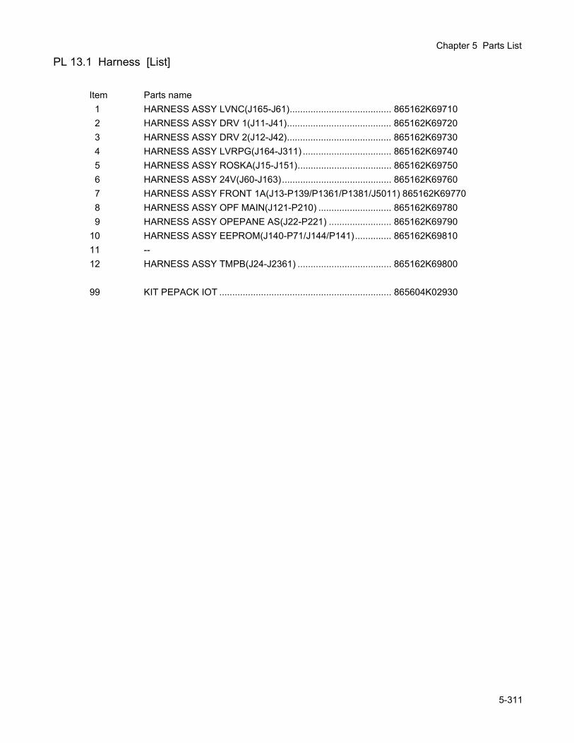
Chapter 5 Parts List
PL 13.1 Harness [List]
Item Parts name1 HARNESS ASSY LVNC(J165-J61)....................................... 865162K697102 HARNESS ASSY DRV 1(J11-J41)........................................ 865162K697203 HARNESS ASSY DRV 2(J12-J42)........................................ 865162K697304 HARNESS ASSY LVRPG(J164-J311) .................................. 865162K697405 HARNESS ASSY ROSKA(J15-J151).................................... 865162K697506 HARNESS ASSY 24V(J60-J163).......................................... 865162K697607 HARNESS ASSY FRONT 1A(J13-P139/P1361/P1381/J5011) 865162K697708 HARNESS ASSY OPF MAIN(J121-P210) ............................ 865162K697809 HARNESS ASSY OPEPANE AS(J22-P221) ........................ 865162K69790
10 HARNESS ASSY EEPROM(J140-P71/J144/P141).............. 865162K6981011 --12 HARNESS ASSY TMPB(J24-J2361) .................................... 865162K69800
99 KIT PEPACK IOT .................................................................. 865604K02930
5-311

5-312

Chapter 6 Principles of Operation

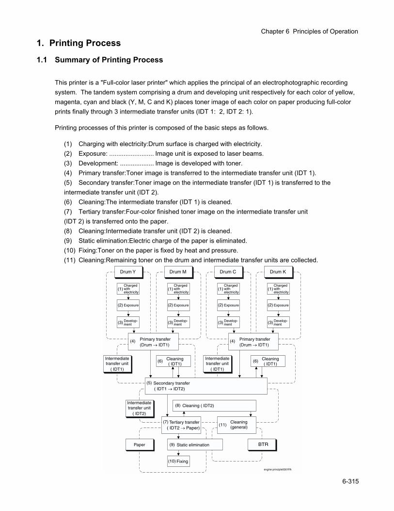
Chapter 6 Principles of Operation
1. Printing Process
1.1 Summary of Printing Process
This printer is a "Full-color laser printer" which applies the principal of an electrophotographic recording system. The tandem system comprising a drum and developing unit respectively for each color of yellow, magenta, cyan and black (Y, M, C and K) places toner image of each color on paper producing full-color prints finally through 3 intermediate transfer units (IDT 1: 2, IDT 2: 1).
Printing processes of this printer is composed of the basic steps as follows.
(1) Charging with electricity:Drum surface is charged with electricity.(2) Exposure: ......................... Image unit is exposed to laser beams.(3) Development: ................... Image is developed with toner.(4) Primary transfer:Toner image is transferred to the intermediate transfer unit (IDT 1).(5) Secondary transfer:Toner image on the intermediate transfer (IDT 1) is transferred to the intermediate transfer unit (IDT 2).(6) Cleaning:The intermediate transfer (IDT 1) is cleaned.(7) Tertiary transfer:Four-color finished toner image on the intermediate transfer unit(IDT 2) is transferred onto the paper.(8) Cleaning:Intermediate transfer unit (IDT 2) is cleaned.(9) Static elimination:Electric charge of the paper is eliminated.(10) Fixing:Toner on the paper is fixed by heat and pressure.(11) Cleaning:Remaining toner on the drum and intermediate transfer units are collected.
Drum Y
Charged with electricity
Drum M Drum C Drum K
BTR
( IDT1 IDT2)
engine principle0001FA
(1)
Exposure(2)
Secondary transfer(5)
( IDT2 Paper)Tertiary transfer(7)
(6)
(8)
(6)
Develop-ment(3)
Cleaning( IDT1)
Cleaning ( IDT2)
(9) Static elimination
(10) Fixing
Paper
(11)Cleaning(general)
Intermediatetransfer unit
( IDT1)
Intermediatetransfer unit
( IDT2)
Cleaning( IDT1)
Intermediatetransfer unit
( IDT1)
(4) Primary transfer(Drum IDT1)
Primary transfer(Drum IDT1)
(4)
Charged with electricity
(1)
Exposure(2)
Develop-ment(3)
Charged with electricity
(1)
Exposure(2)
Develop-ment(3)
Charged with electricity
(1)
Exposure(2)
Develop-ment(3)
6-315
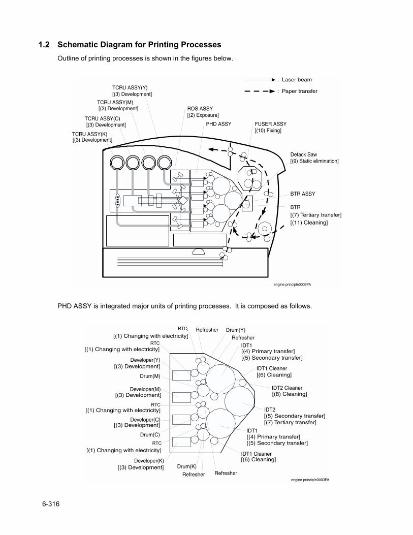
1.2 Schematic Diagram for Printing ProcessesOutline of printing processes is shown in the figures below.
PHD ASSY is integrated major units of printing processes. It is composed as follows.
TCRU ASSY(K)
TCRU ASSY(C)
TCRU ASSY(M)
TCRU ASSY(Y)[(3) Development]
ROS ASSY[(2) Exposure]
PHD ASSY FUSER ASSY[(10) Fixing]
BTR ASSY
engine principle0002FA
[(3) Development]
[(3) Development]
[(3) Development]
BTR[(7) Tertiary transfer][(11) Cleaning]
Detack Saw[(9) Static elimination]
: Laser beam
: Paper transfer
HTC
HTC
HTC
Developer(M)
Developer(Y)
Developer(C)
Developer(K)Drum(K)
Drum(C)
Drum(Y)
Drum(M)
IDT1
IDT1
IDT2
IDT2 Cleaner
IDT1 Cleaner
IDT1 Cleaner
engine principle0003FA
[(1) Changing with electricity]
[(1) Changing with electricity]
[(3) Development]
[(3) Development]
[(3) Development]
Refresher
Refresher
Refresher Refresher
[(4) Primary transfer][(5) Secondary transfer]
[(6) Cleaning]
[(8) Cleaning]
[(4) Primary transfer][(5) Secondary transfer]
[(6) Cleaning]
[(5) Secondary transfer][(7) Tertiary transfer]
[(3) Development]
[(1) Changing with electricity]
HTC[(1) Changing with electricity]
RTC
RTC
RTC
RTC
6-316
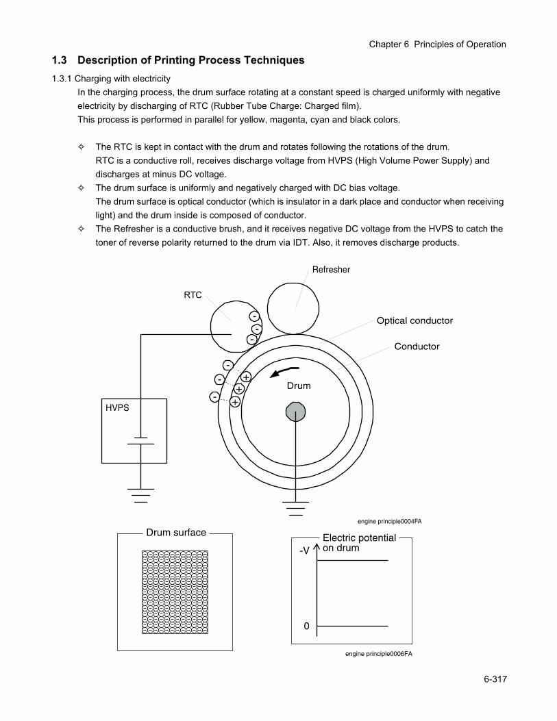
Chapter 6 Principles of Operation
1.3 Description of Printing Process Techniques1.3.1 Charging with electricity
In the charging process, the drum surface rotating at a constant speed is charged uniformly with negative electricity by discharging of RTC (Rubber Tube Charge: Charged film).This process is performed in parallel for yellow, magenta, cyan and black colors.
The RTC is kept in contact with the drum and rotates following the rotations of the drum.RTC is a conductive roll, receives discharge voltage from HVPS (High Volume Power Supply) and discharges at minus DC voltage.
The drum surface is uniformly and negatively charged with DC bias voltage.The drum surface is optical conductor (which is insulator in a dark place and conductor when receiving light) and the drum inside is composed of conductor.
The Refresher is a conductive brush, and it receives negative DC voltage from the HVPS to catch the toner of reverse polarity returned to the drum via IDT. Also, it removes discharge products.
Drum surface
-
+
-
-
++
-
-
-
HTC
Refresher
HVPS
Optical conductor
Conductor
engine principle0004FA
Drum
Electric potentialon drum-V
0
engine principle0006FA
RTC
6-317
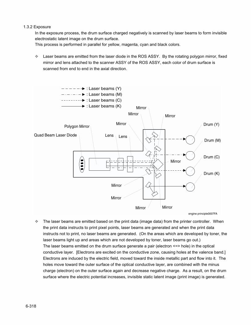
1.3.2 ExposureIn the exposure process, the drum surface charged negatively is scanned by laser beams to form invisible electrostatic latent image on the drum surface.This process is performed in parallel for yellow, magenta, cyan and black colors.
Laser beams are emitted from the laser diode in the ROS ASSY. By the rotating polygon mirror, fixed mirror and lens attached to the scanner ASSY of the ROS ASSY, each color of drum surface is scanned from end to end in the axial direction.
The laser beams are emitted based on the print data (image data) from the printer controller. When the print data instructs to print pixel points, laser beams are generated and when the print data instructs not to print, no laser beams are generated. (On the areas which are developed by toner, the laser beams light up and areas which are not developed by toner, laser beams go out.)The laser beams emitted on the drum surface generate a pair (electron <=> hole) in the optical conductive layer. [Electrons are excited on the conductive zone, causing holes at the valence band.] Electrons are induced by the electric field, moved toward the inside metallic part and flow into it. The holes move toward the outer surface of the optical conductive layer, are combined with the minus charge (electron) on the outer surface again and decrease negative charge. As a result, on the drum surface where the electric potential increases, invisible static latent image (print image) is generated.
engine principle0007FA
Quad Beam Laser Diode
Polygon Mirror
Lens Lens
Mirror
Mirror Mirror
Mirror
Mirror
Mirror
Mirror
MirrorMirror
Drum (Y)
Drum (M)
Drum (C)
Drum (K)
: Laser beams (M): Laser beams (Y)
: Laser beams (C): Laser beams (K)
6-318
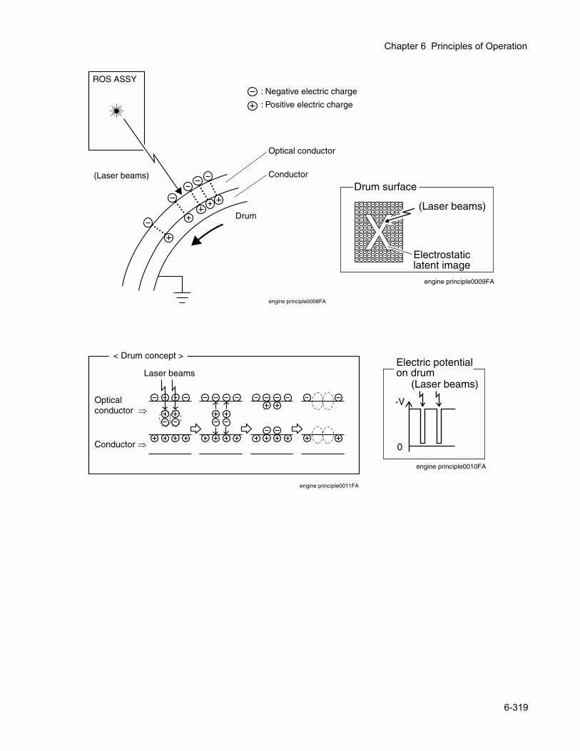
Chapter 6 Principles of Operation
Drum
(Laser beams)
Optical conductor
Conductor
ROS ASSY
engine principle0008FA
: Negative electric charge
: Positive electric charge
engine principle0009FA
Electrostaticlatent image
(Laser beams)
Drum surface
engine principle0011FA
< Drum concept >
Laser beams
Opticalconductor
Conductor
engine principle0010FA
-V
0
(Laser beams)
Electric potentialon drum
6-319
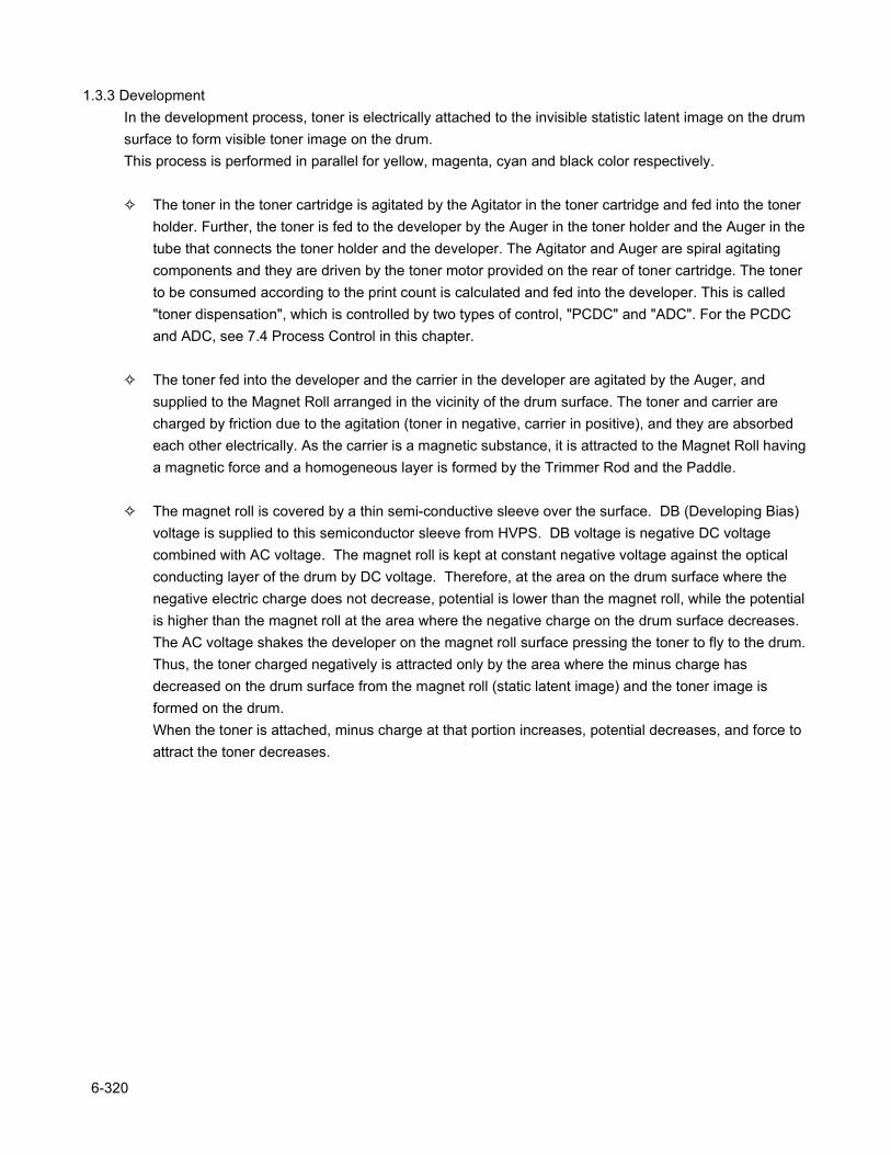
1.3.3 DevelopmentIn the development process, toner is electrically attached to the invisible statistic latent image on the drum surface to form visible toner image on the drum.This process is performed in parallel for yellow, magenta, cyan and black color respectively.
The toner in the toner cartridge is agitated by the Agitator in the toner cartridge and fed into the toner holder. Further, the toner is fed to the developer by the Auger in the toner holder and the Auger in the tube that connects the toner holder and the developer. The Agitator and Auger are spiral agitating components and they are driven by the toner motor provided on the rear of toner cartridge. The toner to be consumed according to the print count is calculated and fed into the developer. This is called "toner dispensation", which is controlled by two types of control, "PCDC" and "ADC". For the PCDC and ADC, see 7.4 Process Control in this chapter.
The toner fed into the developer and the carrier in the developer are agitated by the Auger, and supplied to the Magnet Roll arranged in the vicinity of the drum surface. The toner and carrier are charged by friction due to the agitation (toner in negative, carrier in positive), and they are absorbed each other electrically. As the carrier is a magnetic substance, it is attracted to the Magnet Roll having a magnetic force and a homogeneous layer is formed by the Trimmer Rod and the Paddle.
The magnet roll is covered by a thin semi-conductive sleeve over the surface. DB (Developing Bias) voltage is supplied to this semiconductor sleeve from HVPS. DB voltage is negative DC voltage combined with AC voltage. The magnet roll is kept at constant negative voltage against the optical conducting layer of the drum by DC voltage. Therefore, at the area on the drum surface where the negative electric charge does not decrease, potential is lower than the magnet roll, while the potential is higher than the magnet roll at the area where the negative charge on the drum surface decreases. The AC voltage shakes the developer on the magnet roll surface pressing the toner to fly to the drum.Thus, the toner charged negatively is attracted only by the area where the minus charge has decreased on the drum surface from the magnet roll (static latent image) and the toner image is formed on the drum.When the toner is attached, minus charge at that portion increases, potential decreases, and force to attract the toner decreases.
6-320
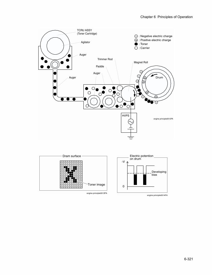
Chapter 6 Principles of Operation
engine principle0013FA
Dram surface
Toner image
engine principle0014FA
Electric potentionon drum
-V
0
Developingbias
+ Drum- +
--
-
-
++
TCRU ASSY(Toner Cartridge)
Magnet RollTrimmer Rod
Auger
Auger
Paddle
-+
: Negative electric charge: Positive electric charge: Toner: Carrier
engine principle0012FA
HVPS
Auger
Agitator
6-321
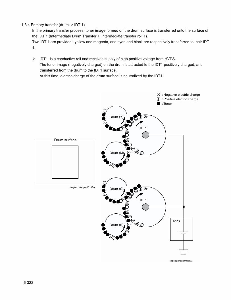
1.3.4 Primary transfer (drum -> IDT 1)In the primary transfer process, toner image formed on the drum surface is transferred onto the surface of the IDT 1 (Intermediate Drum Transfer 1: intermediate transfer roll 1).Two IDT 1 are provided: yellow and magenta, and cyan and black are respectively transferred to their IDT 1.
IDT 1 is a conductive roll and receives supply of high positive voltage from HVPS.The toner image (negatively charged) on the drum is attracted to the IDT1 positively charged, and transferred from the drum to the IDT1 surface.At this time, electric charge of the drum surface is neutralized by the IDT1
Drum (Y)
-+
IDT1-
Drum (M)
-
-
-
-
-
--
++
+
+
++
+ +
+
+
+ +
Drum (C)
IDT1-
Drum (K)
-
-
-
-
-
--
++
+
+
++
+ +
+
+
+ +
HVPS
engine principle0015FA
: Negative electric charge: Positive electric charge: Toner
Drum surface
engine principle0016FA
6-322
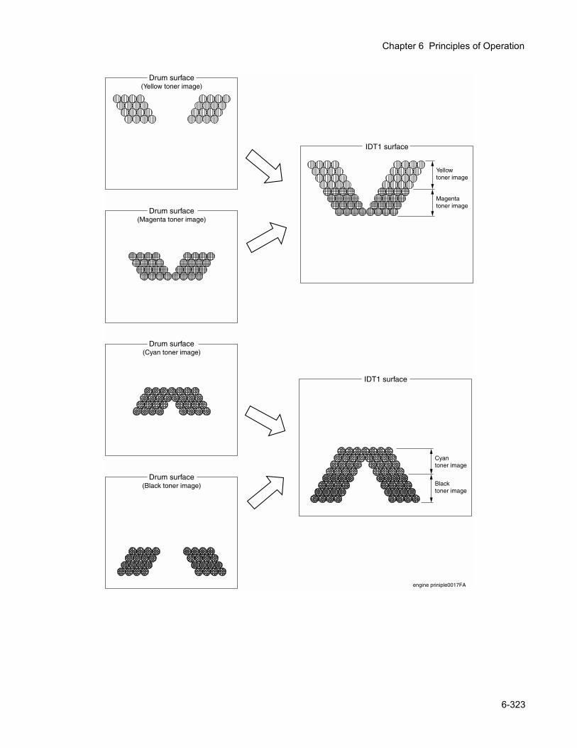
Chapter 6 Principles of Operation
Drum surface(Magenta toner image)
engine priniple0017FA
Yellowtoner image
Magentatoner image
IDT1 surface
Drum surface(Yellow toner image)
Drum surface(Cyan toner image)
Drum surface(Black toner image)
Cyantoner image
Blacktoner image
IDT1 surface
6-323
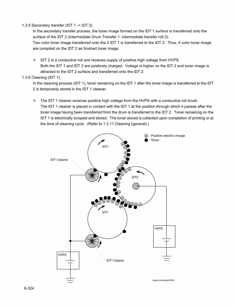
1.3.5 Secondary transfer (IDT 1 -> IDT 2)In the secondary transfer process, the toner image formed on the IDT 1 surface is transferred onto the surface of the IDT 2 (Intermediate Drum Transfer 1: intermediate transfer roll 2).Two color toner image transferred onto the 2 IDT 1 is transferred to the IDT 2. Thus, 4 color toner image are compiled on the IDT 2 as finished toner image.
IDT 2 is a conductive roll and receives supply of positive high voltage from HVPS.Both the IDT 1 and IDT 2 are positively charged. Voltage is higher on the IDT 2 and toner image is attracted to the IDT 2 surface and transferred onto the IDT 2.
1.3.6 Cleaning (IDT 1)In the cleaning process (IDT 1), toner remaining on the IDT 1 after the toner image is transferred to the IDT 2 is temporarily stored in the IDT 1 cleaner.
The IDT 1 cleaner receives positive high voltage from the HVPS with a conductive roll brush.The IDT 1 cleaner is placed in contact with the IDT 1 at the position through which it passes after the toner image having been transferred from the drum is transferred to the IDT 2. Toner remaining on the IDT 1 is electrically scraped and stored. The toner stored is collected upon completion of printing or at the time of cleaning cycle. (Refer to 1.3.11 Cleaning (general).)
+ : Positive electric charge: Toner
IDT1
IDT1
HVPS
IDT2
++
++++
+
+
++
++
+
++
+
++
+ ++++
++++
HVPS
engine principle0018FA
IDT1 Cleaner
IDT1 Cleaner
6-324
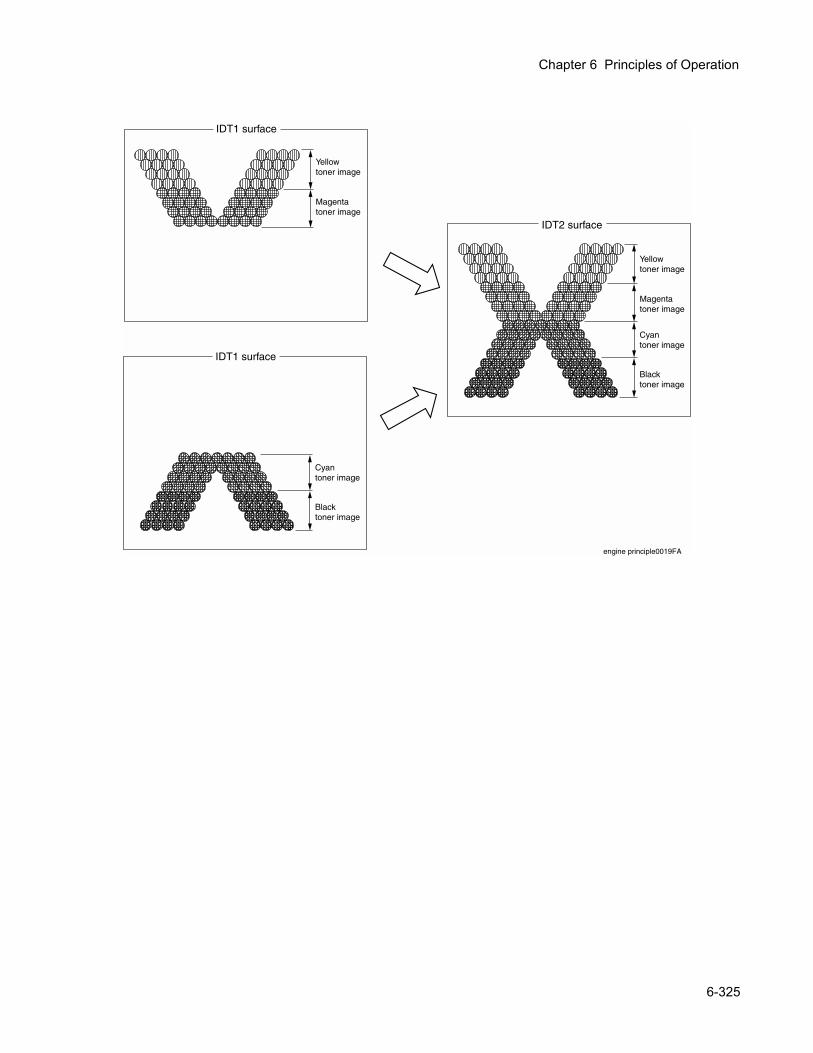
Chapter 6 Principles of Operation
engine principle0019FA
Yellowtoner image
Magentatoner image
IDT1 surface
Yellowtoner image
Magentatoner image
IDT2 surface
Cyantoner image
Blacktoner image
Cyantoner image
Blacktoner image
IDT1 surface
6-325
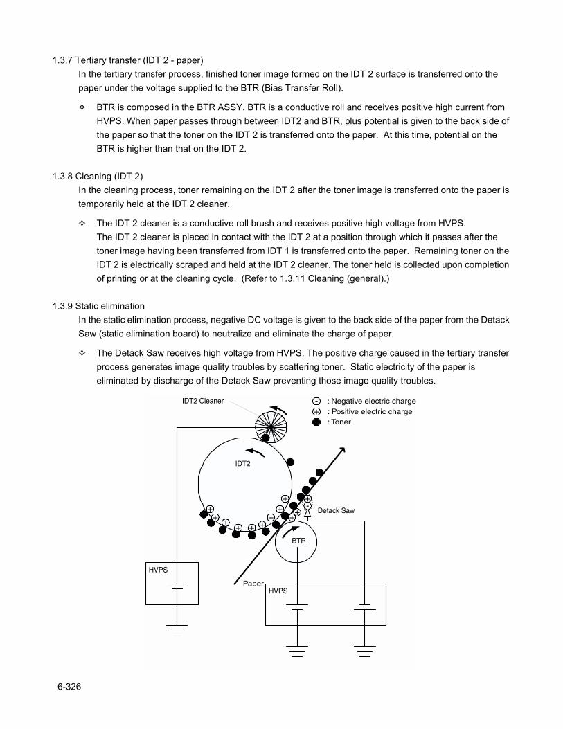
1.3.7 Tertiary transfer (IDT 2 - paper)In the tertiary transfer process, finished toner image formed on the IDT 2 surface is transferred onto the paper under the voltage supplied to the BTR (Bias Transfer Roll).
BTR is composed in the BTR ASSY. BTR is a conductive roll and receives positive high current from HVPS. When paper passes through between IDT2 and BTR, plus potential is given to the back side of the paper so that the toner on the IDT 2 is transferred onto the paper. At this time, potential on the BTR is higher than that on the IDT 2.
1.3.8 Cleaning (IDT 2)In the cleaning process, toner remaining on the IDT 2 after the toner image is transferred onto the paper is temporarily held at the IDT 2 cleaner.
The IDT 2 cleaner is a conductive roll brush and receives positive high voltage from HVPS.The IDT 2 cleaner is placed in contact with the IDT 2 at a position through which it passes after the toner image having been transferred from IDT 1 is transferred onto the paper. Remaining toner on the IDT 2 is electrically scraped and held at the IDT 2 cleaner. The toner held is collected upon completion of printing or at the cleaning cycle. (Refer to 1.3.11 Cleaning (general).)
1.3.9 Static eliminationIn the static elimination process, negative DC voltage is given to the back side of the paper from the Detack Saw (static elimination board) to neutralize and eliminate the charge of paper.
The Detack Saw receives high voltage from HVPS. The positive charge caused in the tertiary transfer process generates image quality troubles by scattering toner. Static electricity of the paper is eliminated by discharge of the Detack Saw preventing those image quality troubles.
HVPS
IDT2
-+
++
+++
++++
++
+
IDT2 Cleaner
Paper
BTR
Detack Saw
HVPS
-
i i i l 0020FA
: Negative electric charge: Positive electric charge: Toner
6-326
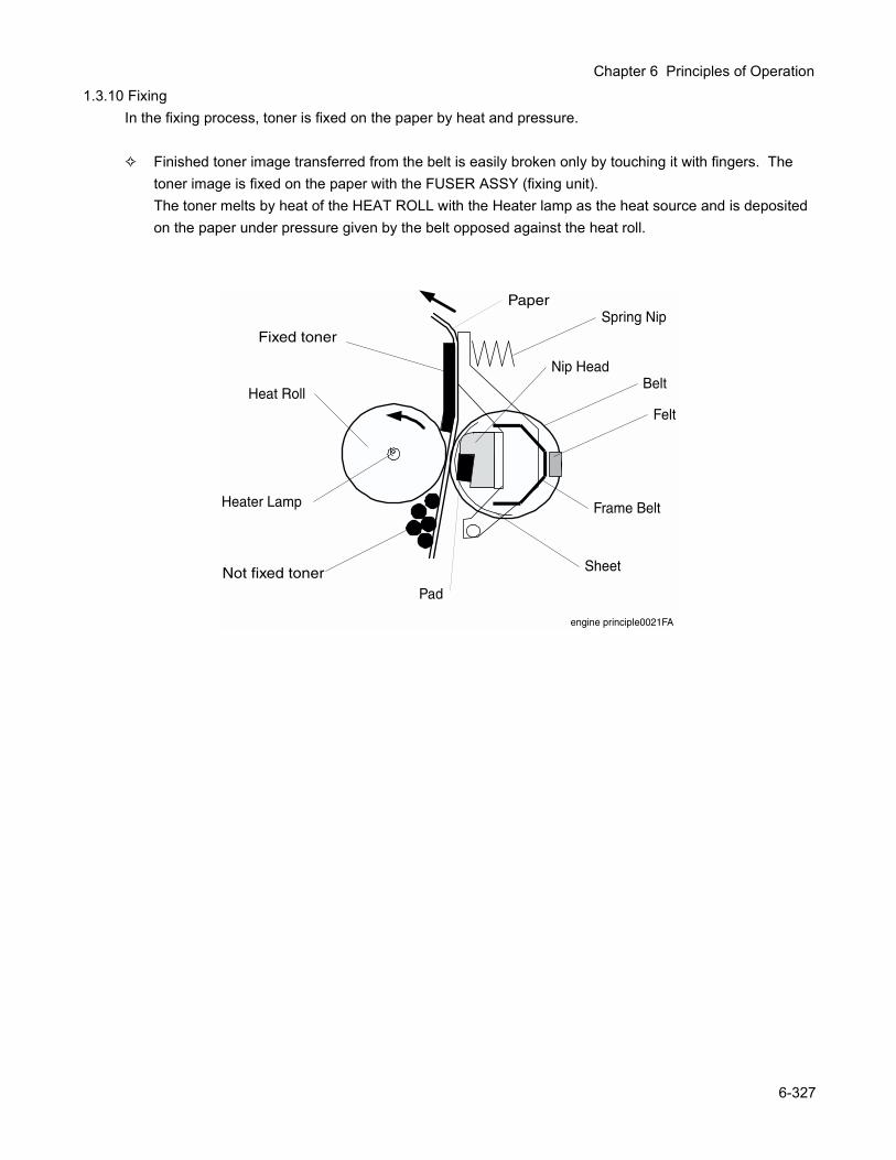
Chapter 6 Principles of Operation
1.3.10 FixingIn the fixing process, toner is fixed on the paper by heat and pressure.
Finished toner image transferred from the belt is easily broken only by touching it with fingers. The toner image is fixed on the paper with the FUSER ASSY (fixing unit).The toner melts by heat of the HEAT ROLL with the Heater lamp as the heat source and is deposited on the paper under pressure given by the belt opposed against the heat roll.
Pad
Sheet
Frame Belt
Belt
Spring Nip
Felt
Nip Head
Heat Roll
Paper
Not fixed toner
Fixed toner
engine principle0021FA
Heater Lamp
6-327
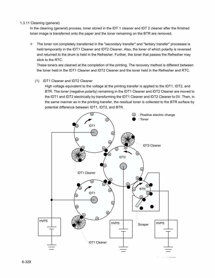
1.3.11 Cleaning (general)In the cleaning (general) process, toner stored in the IDT 1 cleaner and IDT 2 cleaner after the finished toner image is transferred onto the paper and the toner remaining on the BTR are removed.
The toner not completely transferred in the "secondary transfer" and "tertiary transfer" processes is held temporarily in the IDT1 Cleaner and IDT2 Cleaner. Also, the toner of which polarity is reversed and returned to the drum is held in the Refresher. Further, the toner that passes the Refresher may stick to the RTC.These toners are cleaned at the completion of the printing. The recovery method is different between the toner held in the IDT1 Cleaner and IDT2 Cleaner and the toner held in the Refresher and RTC.
(1) IDT1 Cleaner and IDT2 CleanerHigh voltage equivalent to the voltage at the printing transfer is applied to the IDT1, IDT2, and BTR. The toner (negative polarity) remaining in the IDT1 Cleaner and IDT2 Cleaner are moved to the IDT1 and IDT2 electrically by transforming the IDT1 Cleaner and IDT2 Cleaner to 0V. Then, in the same manner as in the printing transfer, the residual toner is collected to the BTR surface by potential difference between IDT1, IDT2, and BTR.
IDT1
IDT1
HVPS
IDT2
HVPS
engine principle0022FA
IDT1 Cleaner
IDT1 Cleaner
BTR
+
+
+
+
+
+
+
+
+
+
++
+
+
+
+
+
++
+
+
+
++
+
+
++
+
++
HVPSScraper
+
IDT2 Cleaner
: Positive electric charge: Toner
6-328
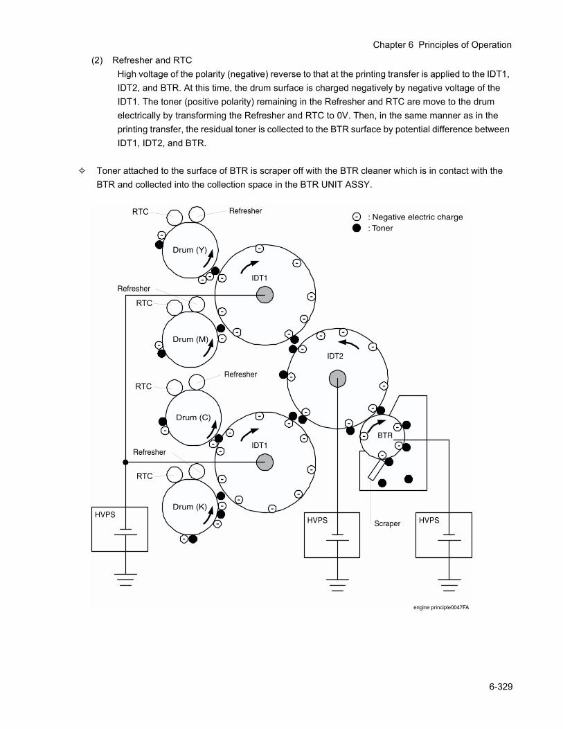
Chapter 6 Principles of Operation
(2) Refresher and RTCHigh voltage of the polarity (negative) reverse to that at the printing transfer is applied to the IDT1, IDT2, and BTR. At this time, the drum surface is charged negatively by negative voltage of the IDT1. The toner (positive polarity) remaining in the Refresher and RTC are move to the drum electrically by transforming the Refresher and RTC to 0V. Then, in the same manner as in the printing transfer, the residual toner is collected to the BTR surface by potential difference between IDT1, IDT2, and BTR.
Toner attached to the surface of BTR is scraper off with the BTR cleaner which is in contact with the BTR and collected into the collection space in the BTR UNIT ASSY.
-
IDT1
IDT1
HVPS
IDT2
HVPS
engine principle0047FA
BTR
-
-
-
-
-
-
-
-
-
-
--
-
-
-
-
-
--
-
-
-
--
-
-
--
-
--
HVPSScraper
Drum (Y)
-
Drum (M)
-
-
--
Drum (C)
-
Drum (K)
-
-
-
-
HTC Refresher
HTC
Refresher
HTC
Refresher
HTC
Refresher
: Negative electric charge: Toner
RTC
RTC
RTC
RTC
6-329
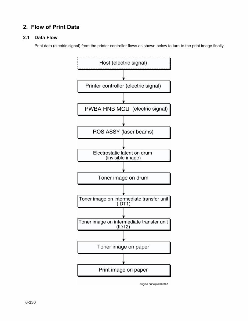
2. Flow of Print Data
2.1 Data FlowPrint data (electric signal) from the printer controller flows as shown below to turn to the print image finally.
engine principle0023FA
Host (electric signal)
Printer controller (electric signal)
HNB MCU WITH CPU (electric signal)
ROS ASSY (laser beams)
Electrostatic latent on drum (invisible image)
Toner image on drum
Toner image on intermediate transfer unit(IDT1)
Toner image on intermediate transfer unit(IDT2)
Toner image on paper
Print image on paper
PWBA HNB MCU
6-330
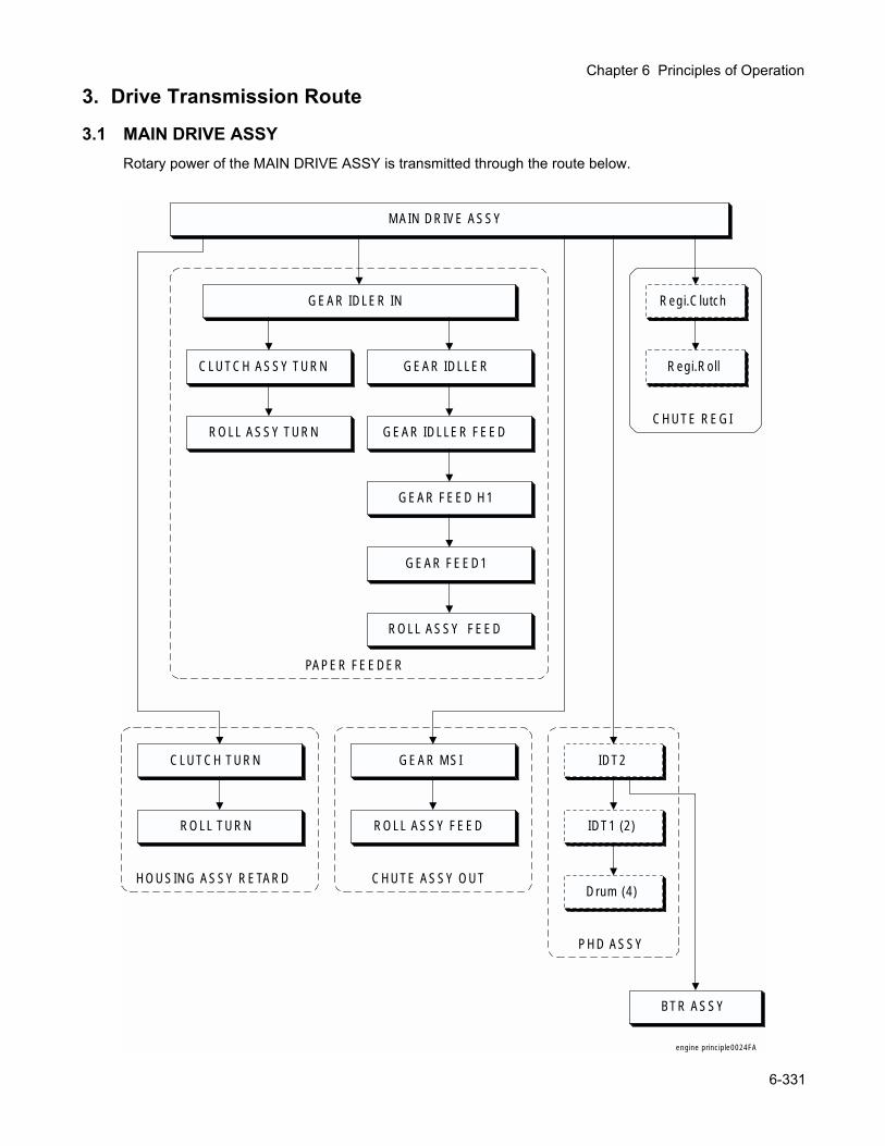
Chapter 6 Principles of Operation
3. Drive Transmission Route
3.1 MAIN DRIVE ASSYRotary power of the MAIN DRIVE ASSY is transmitted through the route below.
MAIN DRIVE ASSY
engine principle0024FA
CLUTCH ASSY TURN
ROLL ASSY TURN GEAR IDLLER FEED
GEAR FEED H1
ROLL ASSY FEED
PAPER FEEDER
CHUTE REGI
Regi.Clutch
Regi.Roll
CLUTCH TURN
ROLL TURN
HOUSING ASSY RETARD
GEAR MSI
ROLL ASSY FEED
CHUTE ASSY OUT
PHD ASSY
IDT2
IDT1 (2)
Drum (4)
BTR ASSY
GEAR IDLER IN
GEAR IDLLER
GEAR FEED1
6-331
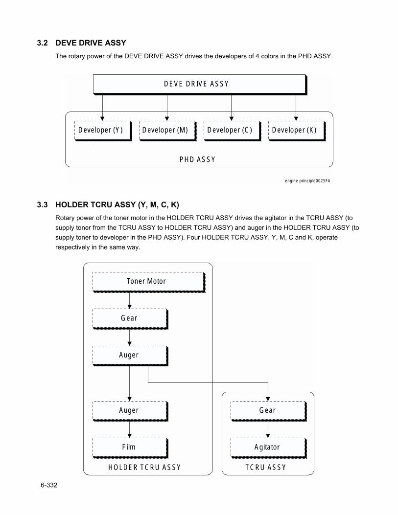
3.2 DEVE DRIVE ASSYThe rotary power of the DEVE DRIVE ASSY drives the developers of 4 colors in the PHD ASSY.
3.3 HOLDER TCRU ASSY (Y, M, C, K)Rotary power of the toner motor in the HOLDER TCRU ASSY drives the agitator in the TCRU ASSY (to supply toner from the TCRU ASSY to HOLDER TCRU ASSY) and auger in the HOLDER TCRU ASSY (to supply toner to developer in the PHD ASSY). Four HOLDER TCRU ASSY, Y, M, C and K, operate respectively in the same way.
DEVE DRIVE ASSY
PHD ASSY
Developer (Y) Developer (M) Developer (C) Developer (K)
engine principle0025FA
HOLDER TCRU ASSY
Toner Motor
Gear
TCRU ASSY
Gear
Auger
Auger
Film Agitator
6-332
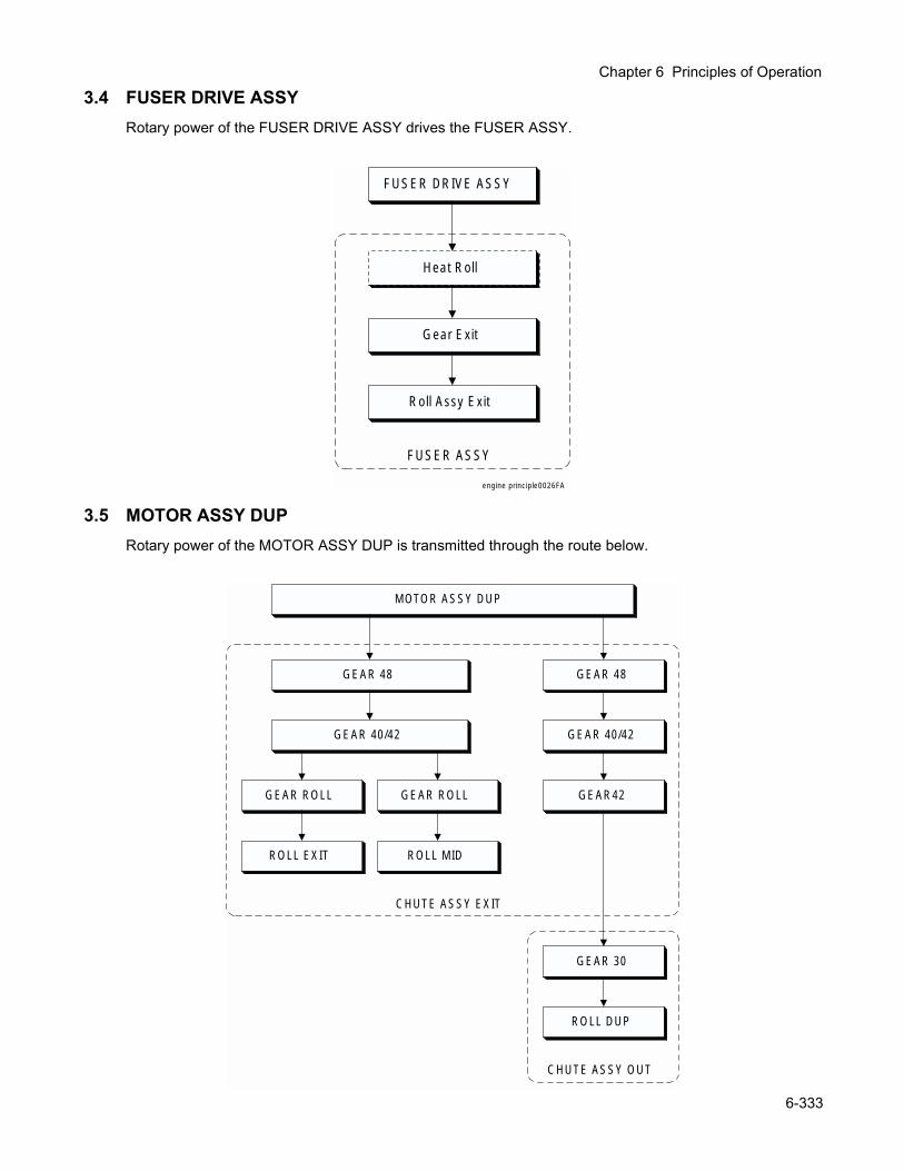
Chapter 6 Principles of Operation
3.4 FUSER DRIVE ASSYRotary power of the FUSER DRIVE ASSY drives the FUSER ASSY.
3.5 MOTOR ASSY DUPRotary power of the MOTOR ASSY DUP is transmitted through the route below.
FUSER DRIVE ASSY
Heat Roll
engine principle0026FA
FUSER ASSY
Gear Exit
Roll Assy Exit
MOTOR ASSY DUP
GEAR ROLL
ROLL EXIT
GEAR ROLL
ROLL MID
GEAR 30
ROLL DUP
CHUTE ASSY EXIT
CHUTE ASSY OUT
GEAR 48
GEAR 40/42
GEAR 48
GEAR 40/42
GEAR42
6-333
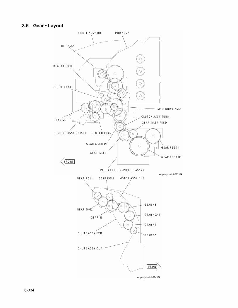
3.6 Gear • Layout
engine principle0029FA
HOUSING ASSY RETARD CLUTCH TURN
CHUTE REGI
REGI CLUTCH
PHD ASSY
BTR ASSY
MAIN DRIVE ASSY
GEAR IDLER IN
GEAR IDLER
GEAR IDLER FEED
GEAR FEED H1
GEAR FEED1
CLUTCH ASSY TURN
PAPER FEEDER (PICK UP ASSY)
CHUTE ASSY OUT
GEAR MSI
FRONT
engine principle0043FA
MOTOR ASSY DUP
CHUTE ASSY EXIT
CHUTE ASSY OUT
GEAR 48
GEAR 40/42
GEAR 48
GEAR 40/42
GEAR 42
GEAR 30
GEAR ROLL GEAR ROLL
FRONT
6-334
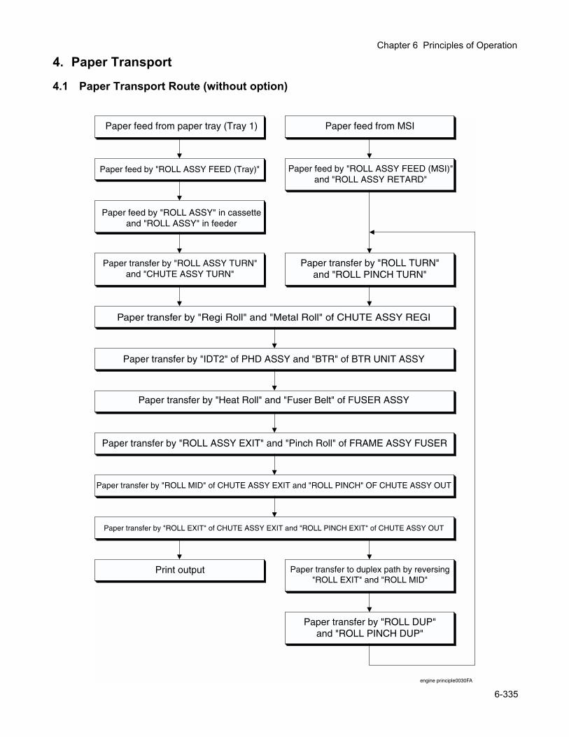
Chapter 6 Principles of Operation
4. Paper Transport
4.1 Paper Transport Route (without option)
Paper transfer by "Regi Roll" and "Metal Roll" of CHUTE ASSY REGI
engine principle0030FA
Paper feed from paper tray (Tray 1)
Print output
Paper transfer by "ROLL DUP"and "ROLL PINCH DUP"
Paper transfer to duplex path by reversing"ROLL EXIT" and "ROLL MID"
Paper feed by "ROLL ASSY" in cassetteand "ROLL ASSY" in feeder
Paper transfer by "ROLL ASSY TURN"and "CHUTE ASSY TURN"
Paper feed from MSI
Paper transfer by "IDT2" of PHD ASSY and "BTR" of BTR UNIT ASSY
Paper transfer by "Heat Roll" and "Fuser Belt" of FUSER ASSY
Paper transfer by "ROLL MID" of CHUTE ASSY EXIT and "ROLL PINCH" OF CHUTE ASSY OUT
Paper transfer by "ROLL EXIT" of CHUTE ASSY EXIT and "ROLL PINCH EXIT" of CHUTE ASSY OUT
Paper transfer by "ROLL ASSY EXIT" and "Pinch Roll" of FRAME ASSY FUSER
Paper feed by "ROLL ASSY FEED (MSI)"and "ROLL ASSY RETARD"
Paper transfer by "ROLL TURN"and "ROLL PINCH TURN"
Paper feed by "ROLL ASSY FEED (Tray)"
6-335
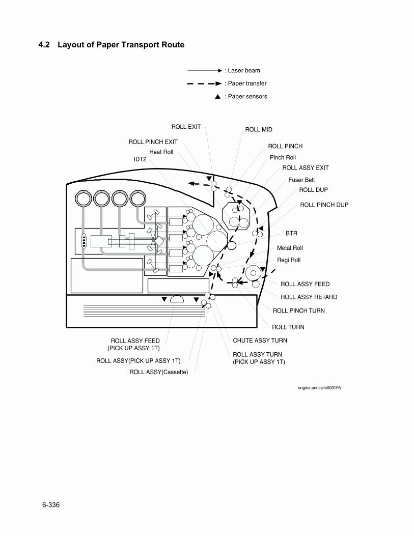
4.2 Layout of Paper Transport Route
ROLL ASSY FEED(PICK UP ASSY 1T)
ROLL ASSY(Cassette)
ROLL ASSY(PICK UP ASSY 1T)ROLL ASSY TURN(PICK UP ASSY 1T)
CHUTE ASSY TURN
ROLL ASSY FEED
ROLL ASSY RETARD
ROLL TURN
ROLL PINCH TURN
Regi Roll
Metal Roll
ROLL PINCH DUP
ROLL DUP
BTR
IDT2
Fuser Belt
Heat Roll
ROLL ASSY EXIT
Pinch Roll
ROLL MIDROLL EXIT
ROLL PINCH EXITROLL PINCH
: Laser beam
: Paper transfer
: Paper sensors
engine principle0031FA
6-336
Chapter 6 Principles of Operation
5. Functions of Major Functional Components
Major functional components comprising the printer are described below referring to their illustrations. Those components are classified into the following blocks based on the configuration of the printer.
Paper Cassette Paper Feeder Housing Assy Retard Front Assy In Chute Assy Out Chute Assy Exit BTR Assy & Fuser Xerographics TCRU Assy Frame & Drive Electrical
6-337
5.1 Paper Cassette5.1.1 Major functions
Side GuideThe Side Guide can move at right angle to the paper transfer direction to align the paper width.
End GuideThe End Guide can move in the paper transfer direction to determine the paper size. The ON/OFF of SWITCH ASSY SIZE (see 5.2 Paper Feeder) varies according to the End Guide position to detect the paper size.
ROLL ASSY (Cassette)The ROLL ASSY (Cassette) and the ROLL ASSY (PICK UP ASSY T1) (see 5.2 Paper Feeder) pinch the paper to feed.
6-338
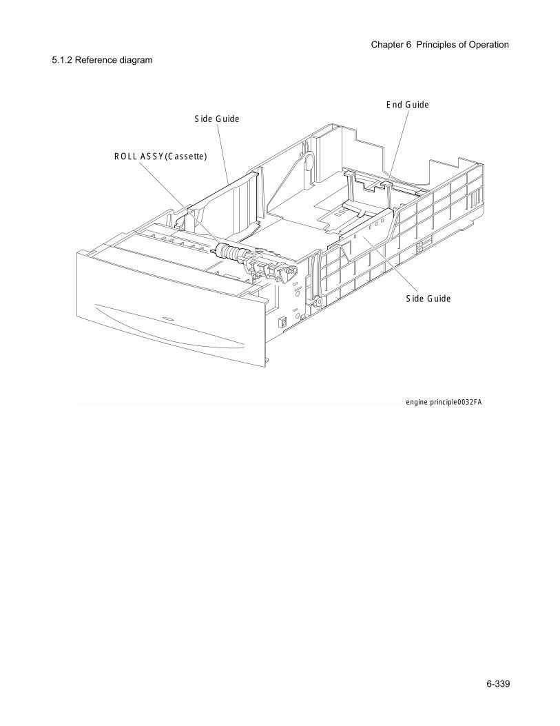
Chapter 6 Principles of Operation
5.1.2 Reference diagramengine principle0032FA
Side Guide
Side Guide
End Guide
ROLL ASSY(Cassette)
6-339
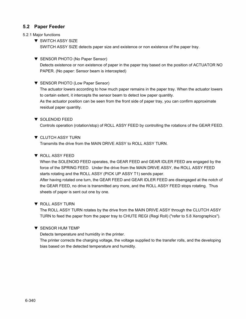
5.2 Paper Feeder5.2.1 Major functions
SWITCH ASSY SIZESWITCH ASSY SIZE detects paper size and existence or non existence of the paper tray.
SENSOR PHOTO (No Paper Sensor)Detects existence or non existence of paper in the paper tray based on the position of ACTUATOR NO PAPER. (No paper: Sensor beam is intercepted)
SENSOR PHOTO (Low Paper Sensor)The actuator lowers according to how much paper remains in the paper tray. When the actuator lowers to certain extent, it intercepts the sensor beam to detect low paper quantity.As the actuator position can be seen from the front side of paper tray, you can confirm approximate residual paper quantity.
SOLENOID FEEDControls operation (rotation/stop) of ROLL ASSY FEED by controlling the rotations of the GEAR FEED.
CLUTCH ASSY TURNTransmits the drive from the MAIN DRIVE ASSY to ROLL ASSY TURN.
ROLL ASSY FEEDWhen the SOLENOID FEED operates, the GEAR FEED and GEAR IDLER FEED are engaged by the force of the SPRING FEED. Under the drive from the MAIN DRIVE ASSY, the ROLL ASSY FEED starts rotating and the ROLL ASSY (PICK UP ASSY T1) sends paper.After having rotated one turn, the GEAR FEED and GEAR IDLER FEED are disengaged at the notch of the GEAR FEED, no drive is transmitted any more, and the ROLL ASSY FEED stops rotating. Thus sheets of paper is sent out one by one.
ROLL ASSY TURNThe ROLL ASSY TURN rotates by the drive from the MAIN DRIVE ASSY through the CLUTCH ASSY TURN to feed the paper from the paper tray to CHUTE REGI (Regi Roll) ("refer to 5.8 Xerographics").
SENSOR HUM TEMPDetects temperature and humidity in the printer.The printer corrects the charging voltage, the voltage supplied to the transfer rolls, and the developing bias based on the detected temperature and humidity.
6-340
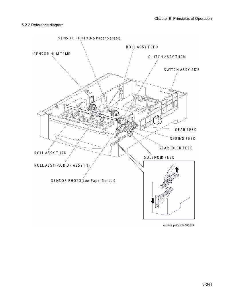
Chapter 6 Principles of Operation
5.2.2 Reference diagramengine principle0033FA
SWITCH ASSY SIZE
SENSOR PHOTO(No Paper Sensor)
SENSOR PHOTO(Low Paper Sensor)
SOLENOID FEED
GEAR IDLER FEED
GEAR FEED
SPRING FEED
CLUTCH ASSY TURN
ROLL ASSY FEED
ROLL ASSY TURN
ROLL ASSY(PICK UP ASSY T1)
SENSOR HUM TEMP
6-341

5.3 Housing Assy Retard5.3.1 Major functions
CLUTCH TURN (MSI Turn Clutch)Transmits the drive from the MAIN DRIVE ASSY to the ROLL TURN.
ROLL TURNThe ROLL TURN is rotated by the drive from the MAIN DRIVE ASSY through the CLUTCH TURN (MSI Turn Clutch) to feed the paper from the manual feed tray to the CHUTE REGI (Regi Roll) (refer to "5.8 Xerographics").
6-342
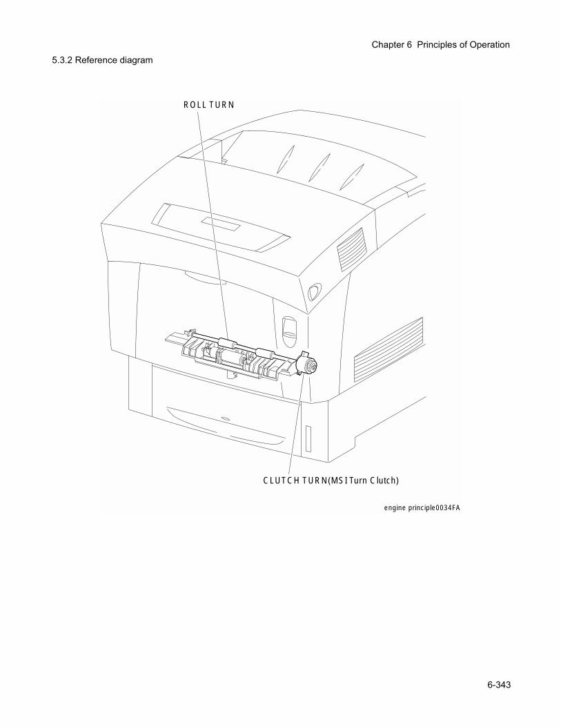
Chapter 6 Principles of Operation
5.3.2 Reference diagramengine principle0034FA
CLUTCH TURN(MSI Turn Clutch)
ROLL TURN
6-343
5.4 Front Assy In5.4.1 Major functions
SENSOR ADC ASSYReads the density of the toner image prepared on the surface of BTR in the BTR UNIT ASSY (refer to "5.7 BTR ASSY & Fuser") and feeds it back to the process control (refer to "7.4 Process Control").
SENSOR TNR FULLDetects that the toner collect space in the BTR UNIT ASSY (refer to "5.7 BTR ASSY & Fuser") has become full of waste toner to be collected.
FUSER DRIVE ASSYSupplies the drive to the FUSER ASSY (refer to "5.7 BTR ASSY & Fuser").
6-344
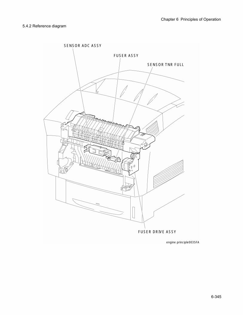
Chapter 6 Principles of Operation
5.4.2 Reference diagramFUSER DRIVE ASSY
SENSOR ADC ASSY
SENSOR TNR FULL
FUSER ASSY
engine principle0035FA
6-345
5.5 Chute Assy Out5.5.1 Major functions
SENSOR PHOTO (Full Stack Sensor)Detects that the prints discharged onto the top cover have accumulated more than specified number of sheets based on the change of position of the actuator.(Full stack: Sensor beam is received)
SENSOR PHOTO (Dup Jam Sensor)Detects that paper has reached and passed through the ROLL DUP based on the change of position of the actuator.(Paper present: Sensor beam is received)
SENSOR PHOTO (MSI No Paper Sensor)Detects existence or non existence of paper on the manual feed tray based on the change of position of the actuator.(No paper: Sensor beam is intercepted)
SOLENOID FEED MSIControls the operation (rotation/stop) of ROLL ASSY FEED by controlling the rotations of the GEAR MSI.
ROLL ASSY FEEDWhen the SOLENOID FEED MSI operates, the GEAR MSI and GEAR IDLER are engaged by the force of the SPRING SOL, the ROLL ASSY FEED starts rotating under the drive from the MAIN DRIVE ASSY, and feeds paper from the manual feed tray.After having rotated one turn, the GEAR MSI and GEAR IDLER are disengaged at the notch of the GEAR MSI, drive is not transmitted any more, and the ROLL ASSY FEED stops rotating. Thus sheets of paper are fed one by one.
ROLL DUPThe ROLL DUP rotates under the drive from the MOTOR ASSY DUP and feeds paper printed on simplex returned from the CHUTE ASSY EXIT to the ROLL TURN (refer to "5.3 Housing Assy Retard)".
6-346
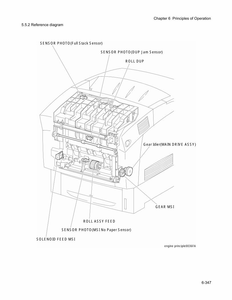
Chapter 6 Principles of Operation
5.5.2 Reference diagramengine principle0036FA
SENSOR PHOTO(Full Stack Sensor)
SENSOR PHOTO(DUP Jam Sensor)
ROLL DUP
SENSOR PHOTO(MSI No Paper Sensor)
ROLL ASSY FEED
Gear Idier(MAIN DRIVE ASSY)
GEAR MSI
SOLENOID FEED MSI
6-347
5.6 Chute Assy Exit5.6.1 Major functions
MOTOR ASSY DUPSupplies drive to the ROLL EXIST, ROLL MID, and ROLL DUP.
ROLL EXITThe ROLL EXIT rotates under the drive from the MOTOR ASSY DUP, and feeds fixed prints onto the top cover. It reverses in the duplex document mode and feeds the prints after fixed on simplex in the REGI direction.
ROLL MIDThe ROLL MID rotates under the drive from the MOTOR ASSY DUP, and feeds fixed prints onto the top cover. It reverses in the duplex document mode and feeds the prints after fixed on simplex in the REGI direction.
6-348
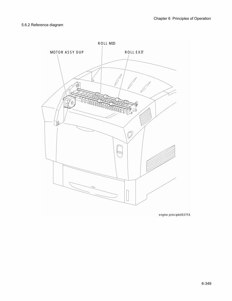
Chapter 6 Principles of Operation
5.6.2 Reference diagramengine principle0037FA
ROLL EXIT
ROLL MID
MOTOR ASSY DUP
6-349
5.7 BTR Assy & Fuser5.7.1 Major functions
FUSER ASSYThe FUSER ASSY fixes toner which was transferred onto the paper but not fixed by the heat and pressure and feeds paper before and after being fixed.The FUSER ASSY mainly consists of the following parts:
• Heat Roll• Belt Unit• Heater Lamp• Roll Assy Exit• Thermostat• Exit Sensor• Temp Sensor
∇ Exit SensorDetects passage of print after fixed based on the change of position of the actuator.
BTR UNIT ASSYThe BTR UNIT ASSY consists of a BTR (Bias Transfer Roll) and a waste toner recovery system.The BTR (Bias Transfer Roll) is opposed to the IDT 2 in the PHD ASSY and transfer the toner image on the IDT 2 onto the paper.
FAN FUSERThe FAN FUSER exhausts the heat of FUSER ASSY to prevent inside temperature from overheating.
6-350
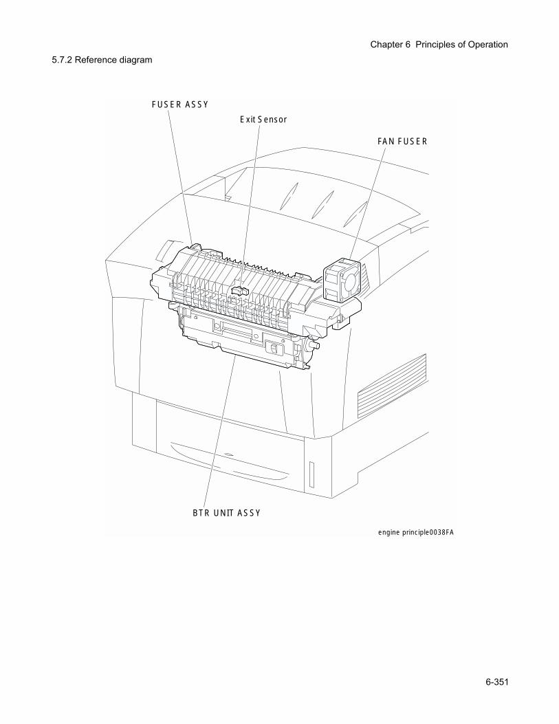
Chapter 6 Principles of Operation
5.7.2 Reference diagramBTR UNIT ASSY
FUSER ASSY
Exit Sensor
FAN FUSER
engine principle0038FA
6-351
5.8 Xerographics 5.8.1 Major functions
ROS ASSYROS ASSY (Raster Output Scanner Assembly) is an exposure unit to generate laser beams to form electrostatic latent image on the drum surface.In this manual, the ROS ASSY is referred to as ROS ASSY.The ROS ASSY mainly consists of the following parts:
• LD ASSY• Scanner ASSY• SOS PWB• Lens• Mirror• Window
PHD ASSY (Imaging Unit)PHD ASSY (Print Head Assembly) carries out a series of operation in the print process such as charging, developing and transfer.PHD ASSY mainly consists of the following parts.
• Drum (Y)• Developer (Y)• Drum (M)• Developer (M)• Drum (C)• Developer (C)• Drum (K)• Developer (K)• RTC (Y)• Refresher (Y)• RTC (M)• Refresher (M)• RTC (C)• Refresher (C)• RTC (K)• Refresher (K)• IDT 1 (2)• IDT 2• IDT 1 cleaner (2)• IDT 2 Cleaner
CHUTE REGI (Regi Clutch) The CHUTE REGI is composed of the Regi Clutch, Regi Roll and Metal Roll.Drive from the MAIN DRIVE ASSY is transmitted to the Regi Roll through the Regi Clutch. Feeds paper from the tray, MSI and duplex path in the PHD ASSY direction. When the paper tip reaches the CHUTE REGI, the CHUTE REGI has the paper make a loop until the Regi Roll starts rotating and correct the skew (feeding the paper in inclined condition) of the tip of the paper.
SENSOR PHOTO (Regi Sensor) Detects that the paper tip has reached the CHUTE REGI.(Paper present: Beam is received)
OHP SENSOR ASSYAs plain paper scatters the radiated light, the OHP SENSOR ASSY can capture the reflected light to detect the paper. The OHP paper scarcely scatters the radiated light, and therefore the OHP SENSOR ASSY cannot capture the reflected light. Thus, whether the paper fed from MSI is plain paper or OHP paper is judged.
6-352
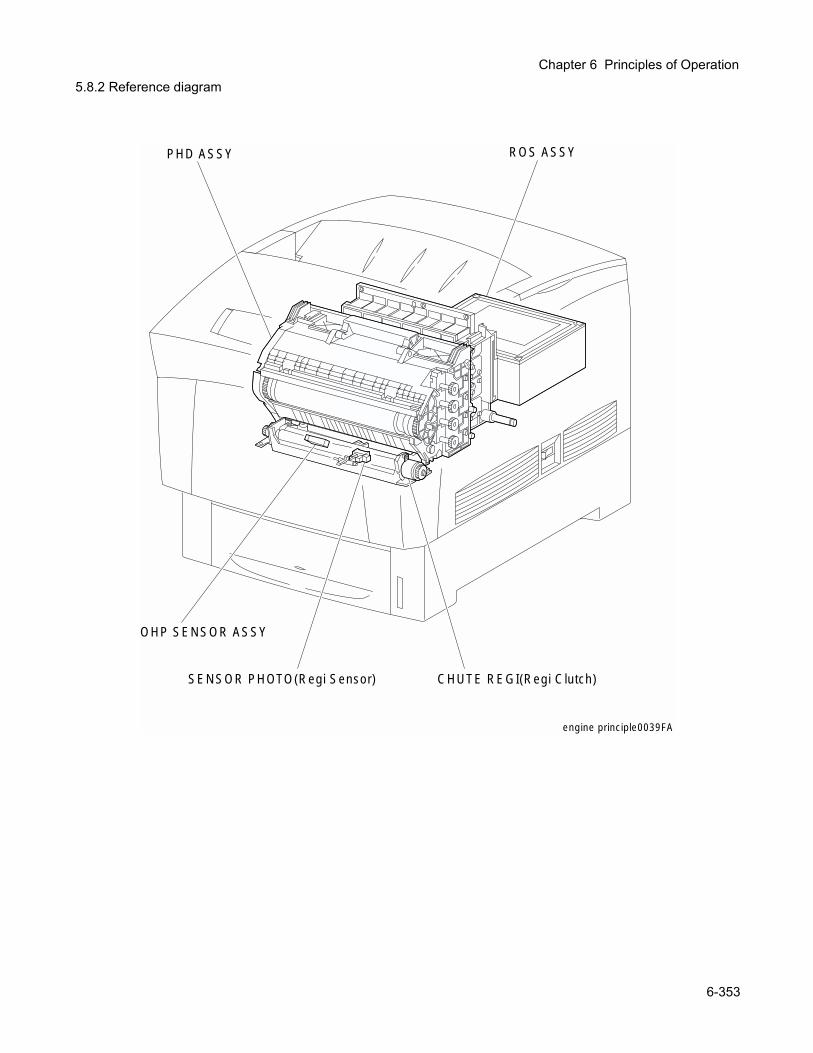
Chapter 6 Principles of Operation
5.8.2 Reference diagramengine principle0039FA
SENSOR PHOTO(Regi Sensor)
OHP SENSOR ASSY
CHUTE REGI(Regi Clutch)
PHD ASSY ROS ASSY
6-353
5.9 TCRU Assy5.9.1 Major functions
SWITCH TCRU ASSY (Y) SWITCH TCRU ASSY (M) SWITCH TCRU ASSY (C) SWITCH TCRU ASSY (K)
Detects whether TCRU ASSY (toner bottle) of each color is installed or not.
SENSOR TONER LOW (Y) SENSOR TONER LOW (M) SENSOR TONER LOW (C) SENSOR TONER LOW (K)
Detects residual toner of each color.
HOLDER TCRU ASSY (1) (Toner Motor: Y) HOLDER TCRU ASSY (2) (Toner Motor: M) HOLDER TCRU ASSY (3) (Toner Motor: C) HOLDER TCRU ASSY (4) (Toner Motor: K)
The toner motor incorporated in the HOLDER TCRU ASSY of each color supplies the drive to the Agitator in the TCRU ASSY of each color and to Auger in the HOLDER TCRU ASSY and supplies toner to the developer incorporated in the PHD ASSY.
TCRU ASSY (Y) TCRU ASSY (M) TCRU ASSY (C) TCRU ASSY (K)
Toner bottle containing tone of each color.
PWBA EEPROM STDPrinter specific information is stored.
S-HVPSSupplies high voltage to perform the “tertiary transfer” and “static elimination” of the print process to the following components.
• BTR in the BTR UNIT ASSY.• Detack Saw in the BTR UNIT ASSY.
6-354
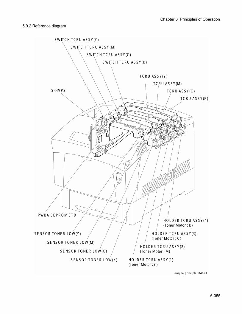
Chapter 6 Principles of Operation
5.9.2 Reference diagramSENSOR TONER LOW(Y)
SENSOR TONER LOW(M)
SENSOR TONER LOW(K)
SENSOR TONER LOW(C)
HOLDER TCRU ASSY(4)(Toner Motor : K)
TCRU ASSY(Y)
TCRU ASSY(M)
TCRU ASSY(K)
HOLDER TCRU ASSY(3)(Toner Motor : C)
HOLDER TCRU ASSY(2)(Toner Motor : M)
HOLDER TCRU ASSY(1)(Toner Motor : Y)
SWITCH TCRU ASSY(K)
SWITCH TCRU ASSY(C)
SWITCH TCRU ASSY(M)
SWITCH TCRU ASSY(Y)
S-HVPS
PWBA EEPROM STD
TCRU ASSY(C)
engine principle0040FA
6-355

5.10 Frame & Drive5.10.1 Major functions
MAIN DRIVE ASSYSupplies the drive to parts as follows.
• PAPER FEEDER• HOUSING ASSY RETARD• CHUTE ASSY OUT (MSI position)• CHUTE REGI• PHD ASSY (IDT 2, IDT 1, Drum)• BTR UNIT ASSY
DEVE DRIVE ASSYSupplies the drive to parts as follows.
• PHD ASSY (Develper)
6-356
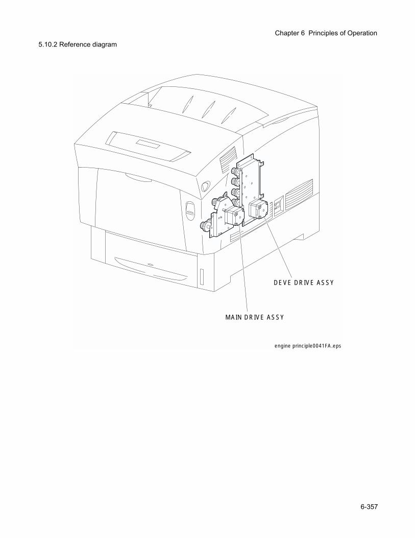
Chapter 6 Principles of Operation
5.10.2 Reference diagramengine principle0041FA.eps
MAIN DRIVE ASSY
DEVE DRIVE ASSY
6-357
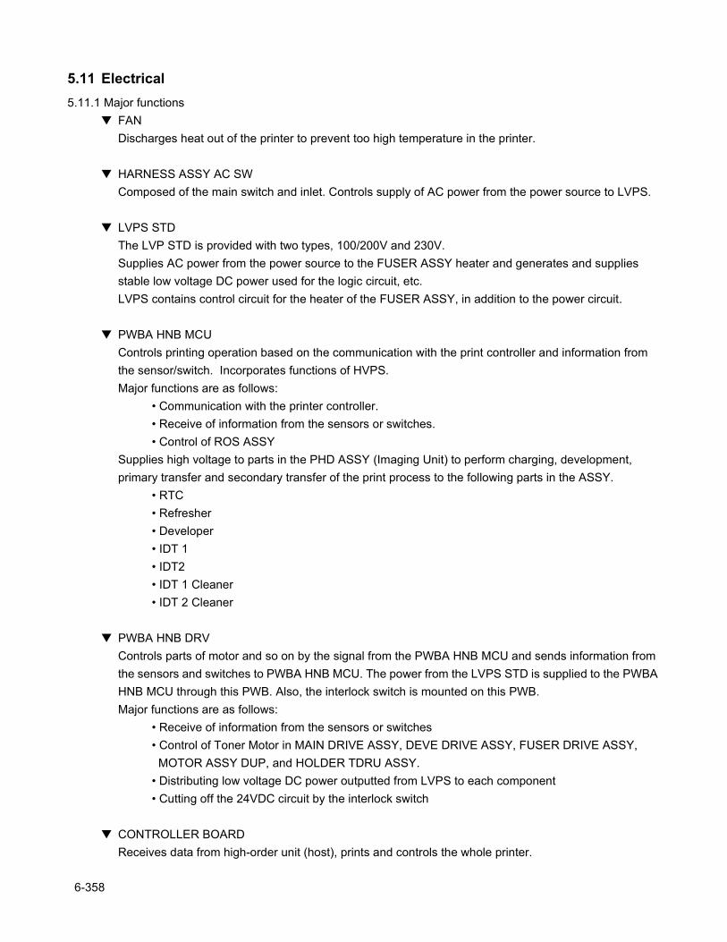
5.11 Electrical5.11.1 Major functions
FANDischarges heat out of the printer to prevent too high temperature in the printer.
HARNESS ASSY AC SWComposed of the main switch and inlet. Controls supply of AC power from the power source to LVPS.
LVPS STDThe LVP STD is provided with two types, 100/200V and 230V.Supplies AC power from the power source to the FUSER ASSY heater and generates and supplies stable low voltage DC power used for the logic circuit, etc.LVPS contains control circuit for the heater of the FUSER ASSY, in addition to the power circuit.
PWBA HNB MCUControls printing operation based on the communication with the print controller and information from the sensor/switch. Incorporates functions of HVPS.Major functions are as follows:
• Communication with the printer controller.• Receive of information from the sensors or switches.• Control of ROS ASSY
Supplies high voltage to parts in the PHD ASSY (Imaging Unit) to perform charging, development, primary transfer and secondary transfer of the print process to the following parts in the ASSY.
• RTC• Refresher• Developer• IDT 1• IDT2• IDT 1 Cleaner• IDT 2 Cleaner
PWBA HNB DRVControls parts of motor and so on by the signal from the PWBA HNB MCU and sends information from the sensors and switches to PWBA HNB MCU. The power from the LVPS STD is supplied to the PWBA HNB MCU through this PWB. Also, the interlock switch is mounted on this PWB.Major functions are as follows:
• Receive of information from the sensors or switches• Control of Toner Motor in MAIN DRIVE ASSY, DEVE DRIVE ASSY, FUSER DRIVE ASSY, MOTOR ASSY DUP, and HOLDER TDRU ASSY.• Distributing low voltage DC power outputted from LVPS to each component• Cutting off the 24VDC circuit by the interlock switch
CONTROLLER BOARDReceives data from high-order unit (host), prints and controls the whole printer.
6-358
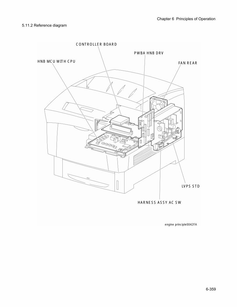
Chapter 6 Principles of Operation
5.11.2 Reference diagramengine principle0042FA
FAN REAR
HARNESS ASSY AC SW
LVPS STD
HNB MCU WITH CPU
PWBA HNB DRV
CONTROLLER BOARD
6-359
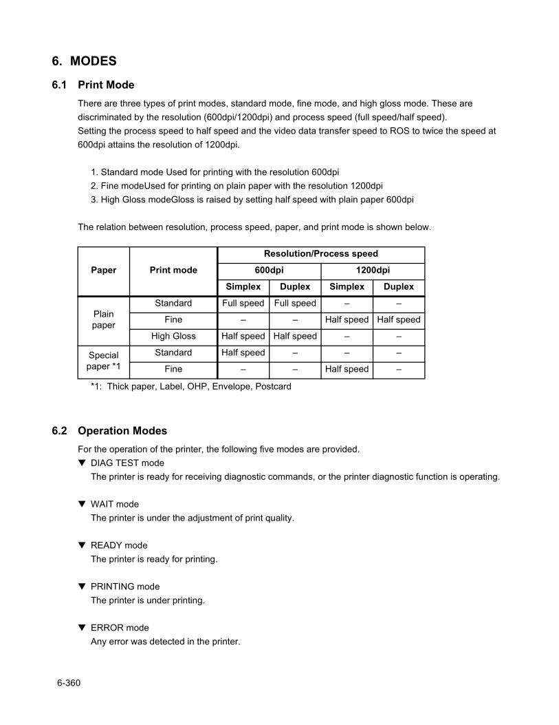
6. MODES
6.1 Print ModeThere are three types of print modes, standard mode, fine mode, and high gloss mode. These are discriminated by the resolution (600dpi/1200dpi) and process speed (full speed/half speed).Setting the process speed to half speed and the video data transfer speed to ROS to twice the speed at 600dpi attains the resolution of 1200dpi.
1. Standard mode Used for printing with the resolution 600dpi2. Fine modeUsed for printing on plain paper with the resolution 1200dpi3. High Gloss modeGloss is raised by setting half speed with plain paper 600dpi
The relation between resolution, process speed, paper, and print mode is shown below.
*1: Thick paper, Label, OHP, Envelope, Postcard
6.2 Operation ModesFor the operation of the printer, the following five modes are provided. DIAG TEST mode
The printer is ready for receiving diagnostic commands, or the printer diagnostic function is operating.
WAIT modeThe printer is under the adjustment of print quality.
READY modeThe printer is ready for printing.
PRINTING modeThe printer is under printing.
ERROR modeAny error was detected in the printer.
Paper Print mode
Resolution/Process speed
600dpi 1200dpi
Simplex Duplex Simplex Duplex
Plain paper
Standard Full speed Full speed – –
Fine – – Half speed Half speed
High Gloss Half speed Half speed – –
Special paper *1
Standard Half speed – – –
Fine – – Half speed –
6-360
Chapter 6 Principles of Operation
7. Control
7.1 Control of Paper Size"ON/OFF of Paper Size Switch of SWITCH ASSY SIZE" and "Diag Tool indication data" are shown in the table below.
Paper Size Switches are indicated as SW1, SW2, and SW3 from the above one.
7.2 Selective Control on Paper Pick-up UnitWhen not controlled by the printer controller, paper pick-up unit selected at the time of turning ON are as follows.
The paper feeder by the paper tray under the printer is called "Tray 1", and the first tray and the second tray in optional TRAY UNIT are called "Tray 2" and "Tray 3" respectively.
7.3 ROS Light Quantity ControlThe image data are entered to the laser diodes in the ROS ASSY as electric signals (data are expressed with high and low voltage values), and the laser diodes convert the image data from electric signals to optical signals (data are expressed with blinking laser beams).Variations in light quantity of laser beams or variations in optical system (such as lenses) or drum sensitivity cannot attain proper electrostatic image, and accordingly the laser diodes monitor the light quantity of laser beams to control the light quantity so as to attain stable and proper electrostatic image.The ROS in this printer has four laser diodes for yellow, magenta, cyan, and black respectively, and the light quantity is automatically adjusted for each color.
Paper Size Paper Size Switch Diag
indication dataSW1 SW2 SW3LEGAL14" (SEF) ON ON ON 00LEGAL13" (SEF) ON ON OFF 01EXECUTIVE (SEF) ON OFF ON 02B5 (SEF) ON OFF OFF 03A4 (SEF) OFF ON ON 04LETTER (SEF) OFF OFF ON 06A5 OFF ON ONNo cassette OFF OFF OFF 07
6-361
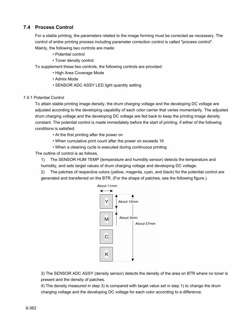
7.4 Process ControlFor a stable printing, the parameters related to the image forming must be corrected as necessary. The control of entire printing process including parameter correction control is called "process control".Mainly, the following two controls are made:
• Potential control• Toner density control
To supplement these two controls, the following controls are provided:• High Area Coverage Mode• Admix Mode• SENSOR ADC ASSY LED light quantity setting
7.4.1 Potential ControlTo attain stable printing image density, the drum charging voltage and the developing DC voltage are adjusted according to the developing capability of each color carrier that varies momentarily. The adjusted drum charging voltage and the developing DC voltage are fed back to keep the printing image density constant. The potential control is made immediately before the start of printing, if either of the following conditions is satisfied:
• At the first printing after the power on• When cumulative print count after the power on exceeds 16• When a cleaning cycle is executed during continuous printing
The outline of control is as follows.1) The SENSOR HUM TEMP (temperature and humidity sensor) detects the temperature and humidity, and sets target values of drum charging voltage and developing DC voltage.2) The patches of respective colors (yellow, magenta, cyan, and black) for the potential control are generated and transferred on the BTR. (For the shape of patches, see the following figure.)
3) The SENSOR ADC ASSY (density sensor) detects the density of the area on BTR where no toner is present and the density of patches.4) The density measured in step 3) is compared with target value set in step 1) to change the drum charging voltage and the developing DC voltage for each color according to a difference.
Y
M
C
K
About 11mm
About 57mm
About 12mm
About 3mm
6-362
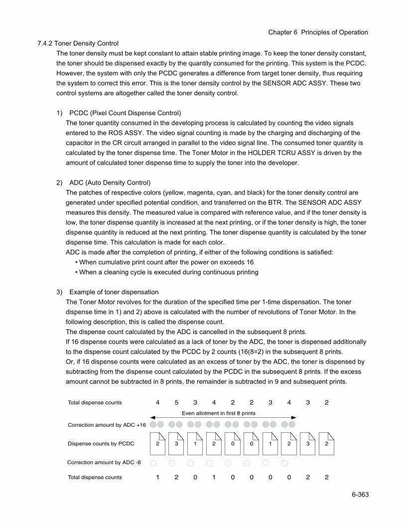
Chapter 6 Principles of Operation
7.4.2 Toner Density ControlThe toner density must be kept constant to attain stable printing image. To keep the toner density constant, the toner should be dispensed exactly by the quantity consumed for the printing. This system is the PCDC. However, the system with only the PCDC generates a difference from target toner density, thus requiring the system to correct this error. This is the toner density control by the SENSOR ADC ASSY. These two control systems are altogether called the toner density control.
1) PCDC (Pixel Count Dispense Control)The toner quantity consumed in the developing process is calculated by counting the video signals entered to the ROS ASSY. The video signal counting is made by the charging and discharging of the capacitor in the CR circuit arranged in parallel to the video signal line. The consumed toner quantity is calculated by the toner dispense time. The Toner Motor in the HOLDER TCRU ASSY is driven by the amount of calculated toner dispense time to supply the toner into the developer.
2) ADC (Auto Density Control)The patches of respective colors (yellow, magenta, cyan, and black) for the toner density control are generated under specified potential condition, and transferred on the BTR. The SENSOR ADC ASSY measures this density. The measured value is compared with reference value, and if the toner density is low, the toner dispense quantity is increased at the next printing, or if the toner density is high, the toner dispense quantity is reduced at the next printing. The toner dispense quantity is calculated by the toner dispense time. This calculation is made for each color.ADC is made after the completion of printing, if either of the following conditions is satisfied:
• When cumulative print count after the power on exceeds 16• When a cleaning cycle is executed during continuous printing
3) Example of toner dispensationThe Toner Motor revolves for the duration of the specified time per 1-time dispensation. The toner dispense time in 1) and 2) above is calculated with the number of revolutions of Toner Motor. In the following description, this is called the dispense count.The dispense count calculated by the ADC is cancelled in the subsequent 8 prints.If 16 dispense counts were calculated as a lack of toner by the ADC, the toner is dispensed additionally to the dispense count calculated by the PCDC by 2 counts (16(8=2) in the subsequent 8 prints.Or, if 16 dispense counts were calculated as an excess of toner by the ADC, the toner is dispensed by subtracting from the dispense count calculated by the PCDC in the subsequent 8 prints. If the excess amount cannot be subtracted in 8 prints, the remainder is subtracted in 9 and subsequent prints.
Total dispense counts
Correction amount by ADC +16
Dispense counts by PCDC
Correction amount by ADC -8
Total dispense counts
2 3 1 2 0 0 1 2 3 2
Even allotment in first 8 prints
4 5 3 4 2 2 3 4 3 2
1 2 0 1 0 0 0 0 2 2
6-363

7.4.3 High Area Coverage ModeA continuous printing of the image of area coverage exceeding the toner dispense capability causes the toner density in the developer to be lowered.The High Area Coverage Mode extends the next page feed and dispenses the toner during this time, if the toner dispense time reached the specified value during a continuous printing.
7.4.4 Admix ModeEven the High Area Coverage Mode may not be able to cope with the reduction of toner density in the developer. Also, if the machine used in high humidity environment is relocated to the place in low humidity environment, the reference value of toner density is different in respective environments, thus causing large discrepancy between measured value by SENSOR ADC ASSY and reference value of toner density.The Admix Mode dispenses the toner immediately to prevent the reduction of toner density, if the patch density result measured by the SENSOR ADC ASSY is far lower than the reference value when the patches for toner density control are generated.
7.4.5 LED Light Quantity Control of SENSOR ADC ASSYThe SENSOR ADC ASSY is a reflection type density sensor that radiates the light to an objective from the LED in the sensor and detects the reflected light from the objective to output electric signal according to the light quantity. For exact density measurement, the sensor output value (reflected light quantity) must be the specified value when no toner is put on the BTR as an objective. The reflected light quantity varies depending on the BTR surface condition or dirty condition of SENSOR ADC ASSY surface. The light quantity emitted from the LED is controlled so that the reflected light quantity satisfies the specified value.This control is made in two ways; one to set the light quantity so that the reflected light quantity satisfies the specified value, and one to adjust the subsequent light quantity to be within the tolerance.
1) Light quantity settingThe reflected light quantity may vary largely, if the BTR UNIT ASSY was replaced or the SENSOR ADC ASSY was cleaned. Assuming this fact, the light quantity is set when the power is turned on, or the front cover is opened and closed.The light quantity of LED is increased gradually, and the set value is fixed when the output of SENSOR ADC ASSY exceeds the specified value. At this time, if the output of SENSOR ADC ASSY does not reach the specified value even though the light quantity is increased to the upper limit, the controller judges the sensor as dirty. Also, the controller judges the sensor as faulty in the event of extremely high output.
2) Light quantity adjustmentAt the execution of ADC, the light quantity adjustment is made immediately before the patches for toner density control are generated.The light is emitted from the LED with current setting of light quantity to check if the output value of the SENSOR ADC ASSY is within the specified range. If the output value is low, the light quantity is increased by the specified amount at the next ADC, or if high, the light quantity is reduced at the next ADC.At this time, if the output value is less than the first lower limit, the controller judges the sensor as dirty and outputs the warning. Further, if less than the second lower limit, the controller judges the sensor as faulty and stops the printing.
6-364
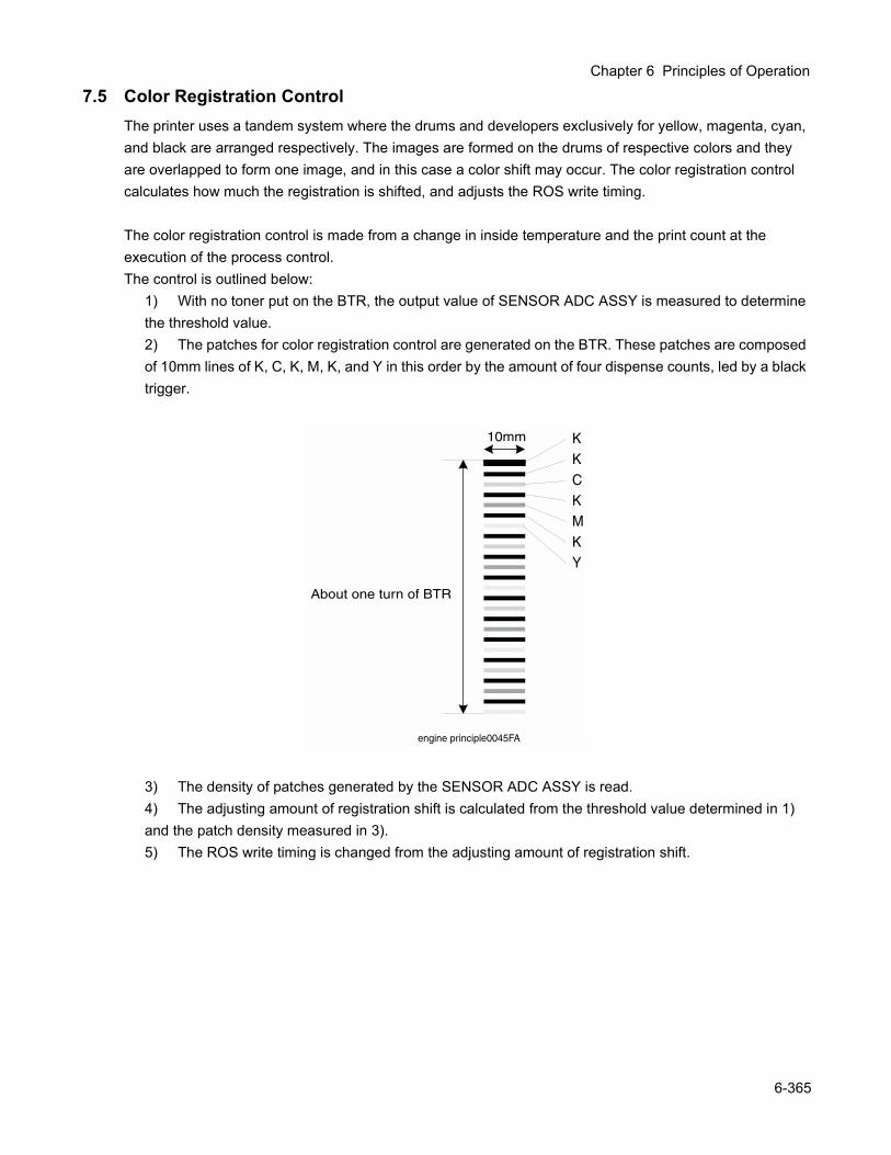
Chapter 6 Principles of Operation
7.5 Color Registration ControlThe printer uses a tandem system where the drums and developers exclusively for yellow, magenta, cyan, and black are arranged respectively. The images are formed on the drums of respective colors and they are overlapped to form one image, and in this case a color shift may occur. The color registration control calculates how much the registration is shifted, and adjusts the ROS write timing.
The color registration control is made from a change in inside temperature and the print count at the execution of the process control.The control is outlined below:
1) With no toner put on the BTR, the output value of SENSOR ADC ASSY is measured to determine the threshold value.2) The patches for color registration control are generated on the BTR. These patches are composed of 10mm lines of K, C, K, M, K, and Y in this order by the amount of four dispense counts, led by a black trigger.
3) The density of patches generated by the SENSOR ADC ASSY is read.4) The adjusting amount of registration shift is calculated from the threshold value determined in 1) and the patch density measured in 3).5) The ROS write timing is changed from the adjusting amount of registration shift.
10mm
About one turn of BTR
engine principle0045FA
KKCKMKY
6-365
7.6 BTR UNIT ASSY Control7.6.1 Detecting the Installation of BTR UNIT ASSY
Whether the BTR UNIT ASSY is installed is detected when the power is turned on, or the front cover is opened and closed. The sensor for detecting the installation is not provided, but judgment is made from the output of the SENSOR ADC ASSY.The light is emitted from the LED of SENSOR ADC ASSY with the specified light quantity, and if the output of the SENSOR ADC ASSY is larger than the specified value, the controller judges as installation. If the operation stops by a jam, the toner image could be put on the BTR and in such a case, the sensor output is reduced, causing the controller to judge as uninstallation. To prevent this wrong detection, the BTR is rotated by a half turn if the output is less than the specified value. Then, when the output of the SENSOR ADC ASSY is larger than the specified value, the controller judges as installation, or if less than the specified value, the controller judges as uninstallation.
7.6.2 Detecting the Life of BTR UNIT ASSYThe BTR UNIT ASSY consists of a BTR and a waste toner recovery system. The life of the BTR UNIT ASSY is detected when the toner recovery space has become full.The full toner recovery space is detected by the SENSOR TNR FULL.1) Check timing of full waste toner recovery space
• When the power is turned on, or the front cover is opened and closed• When paper is outputted
2) Output of "BTR Life Warning"The "BTR Life Warning" is outputted when the SENSOR TNR FULL detects the full toner recovery space.
3) Output of "BTR Life Error"After the output of "BTR Life Warning", the print count and the toner dispense time are counted up, and if total counts exceed the specified value, the "BTR Life Error" is outputted.
4) Reset of "BTR Life Warning"/"BTR Life Error"The "BTR Life Warning" and "BTR Life Error" are reset, if the SENSOR TNR FULL does not detect the full toner recovery space when the power is turned on, or the front cover is opened and closed.
6-366
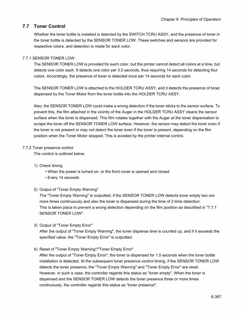
Chapter 6 Principles of Operation
7.7 Toner ControlWhether the toner bottle is installed is detected by the SWITCH TCRU ASSY, and the presence of toner in the toner bottle is detected by the SENSOR TONER LOW. These switches and sensors are provided for respective colors, and detection is made for each color.
7.7.1 SENSOR TONER LOWThe SENSOR TONER LOW is provided for each color, but the printer cannot detect all colors at a time, but detects one color each. It detects one color per 3.5 seconds, thus requiring 14 seconds for detecting four colors. Accordingly, the presence of toner is detected once per 14 seconds for each color.
The SENSOR TONER LOW is attached to the HOLDER TCRU ASSY, and it detects the presence of toner dispensed by the Toner Motor from the toner bottle into the HOLDER TCRU ASSY.
Also, the SENSOR TONER LOW could make a wrong detection if the toner sticks to the sensor surface. To prevent this, the film attached in the vicinity of the Auger in the HOLDER TCRU ASSY cleans the sensor surface when the toner is dispensed. This film rotates together with the Auger at the toner dispensation to scrape the toner off the SENSOR TONER LOW surface. However, the sensor may detect the toner even if the toner is not present or may not detect the toner even if the toner is present, depending on the film position when the Toner Motor stopped. This is avoided by the printer internal control.
7.7.2 Toner presence controlThe control is outlined below.
1) Check timing• When the power is turned on, or the front cover is opened and closed• Every 14 seconds
2) Output of "Toner Empty Warning"The "Toner Empty Warning" is outputted, if the SENSOR TONER LOW detects toner empty two ore more times continuously and also the toner is dispensed during the time of 2-time detection.This is taken place to prevent a wrong detection depending on the film position as described in "7.7.1 SENSOR TONER LOW".
3) Output of "Toner Empty Error"After the output of "Toner Empty Warning", the toner dispense time is counted up, and if it exceeds the specified value, the "Toner Empty Error" is outputted.
4) Reset of "Toner Empty Warning"/"Toner Empty Error"After the output of "Toner Empty Error", the toner is dispensed for 1.5 seconds when the toner bottle installation is detected. At the subsequent toner presence control timing, if the SENSOR TONER LOW detects the toner presence, the "Toner Empty Warning" and "Toner Empty Error" are reset.However, in such a case, the controller regards this status as "toner empty". When the toner is dispensed and the SENSOR TONER LOW detects the toner presence three or more times continuously, the controller regards this status as "toner presence".
6-367
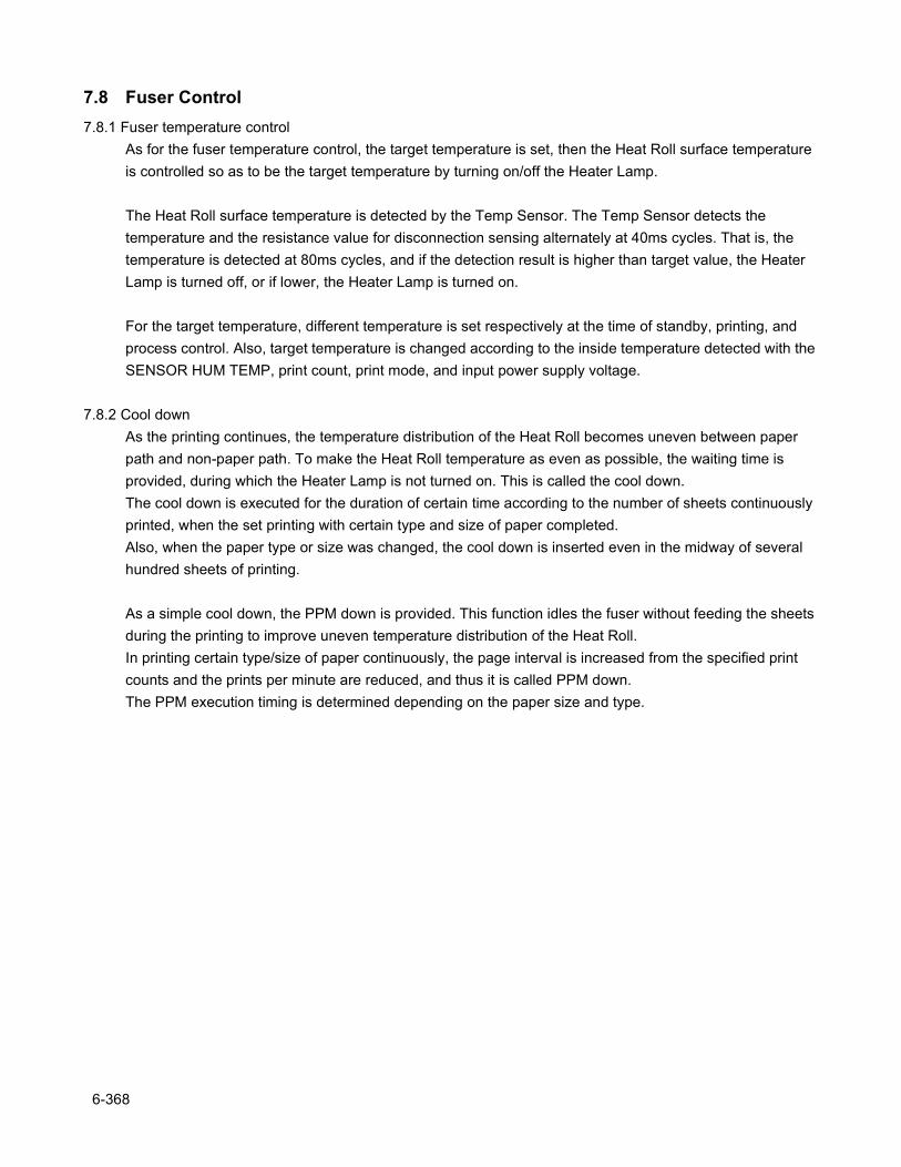
7.8 Fuser Control7.8.1 Fuser temperature control
As for the fuser temperature control, the target temperature is set, then the Heat Roll surface temperature is controlled so as to be the target temperature by turning on/off the Heater Lamp.
The Heat Roll surface temperature is detected by the Temp Sensor. The Temp Sensor detects the temperature and the resistance value for disconnection sensing alternately at 40ms cycles. That is, the temperature is detected at 80ms cycles, and if the detection result is higher than target value, the Heater Lamp is turned off, or if lower, the Heater Lamp is turned on.
For the target temperature, different temperature is set respectively at the time of standby, printing, and process control. Also, target temperature is changed according to the inside temperature detected with the SENSOR HUM TEMP, print count, print mode, and input power supply voltage.
7.8.2 Cool downAs the printing continues, the temperature distribution of the Heat Roll becomes uneven between paper path and non-paper path. To make the Heat Roll temperature as even as possible, the waiting time is provided, during which the Heater Lamp is not turned on. This is called the cool down.The cool down is executed for the duration of certain time according to the number of sheets continuously printed, when the set printing with certain type and size of paper completed.Also, when the paper type or size was changed, the cool down is inserted even in the midway of several hundred sheets of printing.
As a simple cool down, the PPM down is provided. This function idles the fuser without feeding the sheets during the printing to improve uneven temperature distribution of the Heat Roll.In printing certain type/size of paper continuously, the page interval is increased from the specified print counts and the prints per minute are reduced, and thus it is called PPM down.The PPM execution timing is determined depending on the paper size and type.
6-368

Chapter 7 Wiring Diagrams and Signal Information

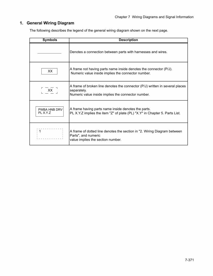
Chapter 7 Wiring Diagrams and Signal Information
1. General Wiring DiagramThe following describes the legend of the general wiring diagram shown on the next page.
Symbols Description
Denotes a connection between parts with harnesses and wires.
A frame not having parts name inside denotes the connector (P/J). Numeric value inside implies the connector number.
A frame of broken line denotes the connector (P/J) written in several places separately.Numeric value inside implies the connector number.
A frame having parts name inside denotes the parts.PL X.Y.Z implies the item "Z" of plate (PL) "X.Y" in Chapter 5. Parts List.
A frame of dotted line denotes the section in "2. Wiring Diagram between Parts", and numeric value implies the section number.
XX
XX
PWBA HNB DRVPL X.Y.Z
1
7-371
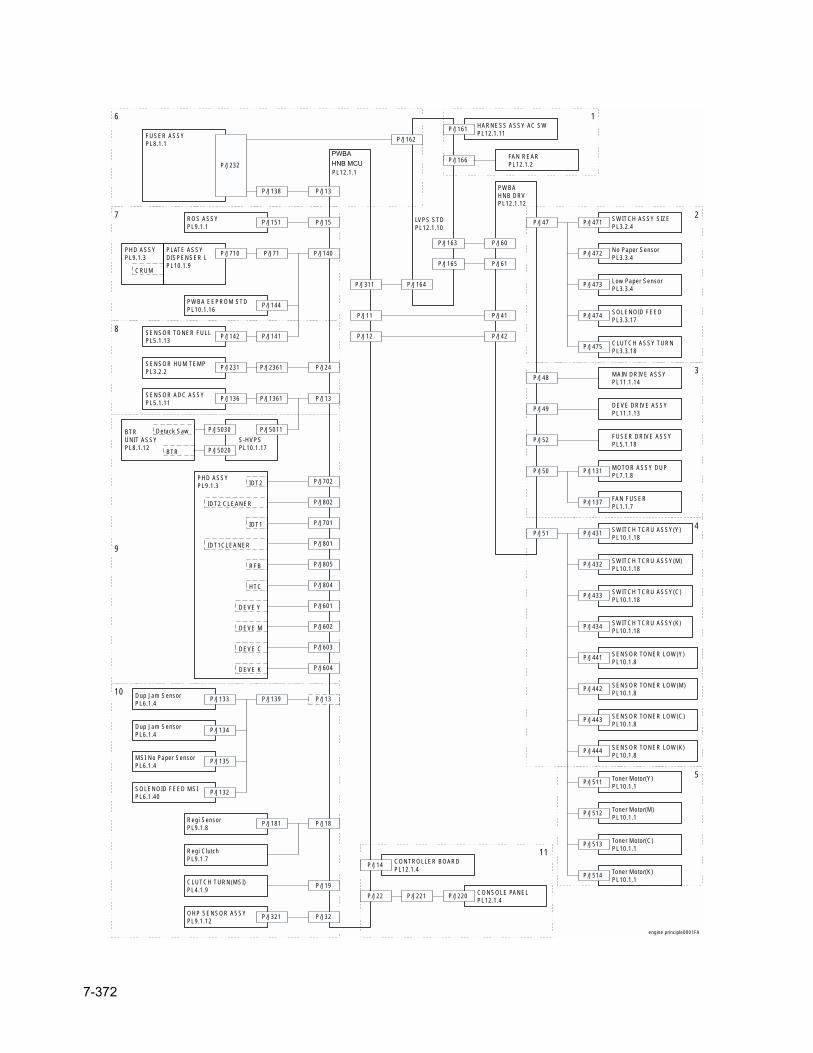
CONSOLE PANELPL12.1.4
CONTROLLER BOARDPL12.1.4
HARNESS ASSY AC SWPL12.1.11
S-HVPSPL10.1.17
PLATE ASSYDISPENSER LPL10.1.9
No Paper SensorPL3.3.4
SWITCH ASSY SIZEPL3.2.4
PWBAHNB DRVPL12.1.12
P/J47
HNB MCUWITH CPUPL12.1.1
P/J471
Low Paper SensorPL3.3.4
SOLENOID FEEDPL3.3.17
CLUTCH ASSY TURNPL3.3.18
MAIN DRIVE ASSYPL11.1.14
DEVE DRIVE ASSYPL11.1.13
P/J52 FUSER DRIVE ASSYPL5.1.18
MOTOR ASSY DUPPL7.1.8
FAN FUSERPL1.1.7
P/J51 SWITCH TCRU ASSY(Y)PL10.1.18
P/J431
SWITCH TCRU ASSY(M)PL10.1.18
P/J432
SWITCH TCRU ASSY(C)PL10.1.18
P/J433
SWITCH TCRU ASSY(K)PL10.1.18
P/J434
SENSOR TONER LOW(Y)PL10.1.8
P/J441
SENSOR TONER LOW(M)PL10.1.8
P/J442
SENSOR TONER LOW(C)PL10.1.8
P/J443
SENSOR TONER LOW(K)PL10.1.8
P/J444
Toner Motor(Y)PL10.1.1
Toner Motor(M)PL10.1.1
Toner Motor(C)PL10.1.1
Toner Motor(K)PL10.1.1
P/J514
ROS ASSYPL9.1.1
P/J151
P/J71P/J710PHD ASSYPL9.1.3
CRUM
PWBA EEPROM STDPL10.1.16
P/J144
SENSOR TONER FULLPL5.1.13
P/J141P/J142
P/J24SENSOR HUM TEMPPL3.2.2
P/J2361P/J231
P/J13SENSOR ADC ASSYPL5.1.11
P/J1361P/J136
BTRUNIT ASSYPL8.1.12
P/J5011P/J5030
P/J5020
Detack Saw
BTR
PHD ASSYPL9.1.3 IDT2
IDT2 CLEANER
IDT1
IDT1CLEANER
RFB
HTC
DEVE Y
DEVE M
DEVE C
DEVE K
P/J601
P/J13Dup Jam SensorPL6.1.4
P/J139P/J133
Dup Jam SensorPL6.1.4
P/J134
MSI No Paper SensorPL6.1.4
P/J135
SOLENOID FEED MSIPL6.1.40
P/J132
Regi SensorPL9.1.8
P/J181
Regi ClutchPL9.1.7
CLUTCH TURN(MSI)PL4.1.9
OHP SENSOR ASSYPL9.1.12
P/J321
LVPS STDPL12.1.10
P/J166 FAN REARPL12.1.2
P/J161
P/J60
P/J61
P/J164
P/J41
P/J42
FUSER ASSYPL8.1.1
P/J232
P/J138 P/J13
P/J162
P/J14
P/J22 P/J221 P/J220
1
2
3
4
5
6
7
8
9
10
11
engine principle0001FA
P/J15
P/J140
P/J702
P/J802
P/J701
P/J804
P/J805
P/J801
P/J602
P/J603
P/J604
P/J18
P/J19
P/J32
P/J513
P/J512
P/J511
P/J137
P/J131P/J50
P/J49
P/J48
P/J475
P/J474
P/J473
P/J472
P/J163
P/J165
P/J311
P/J11
P/J12
PWBAHNB MCU
7-372
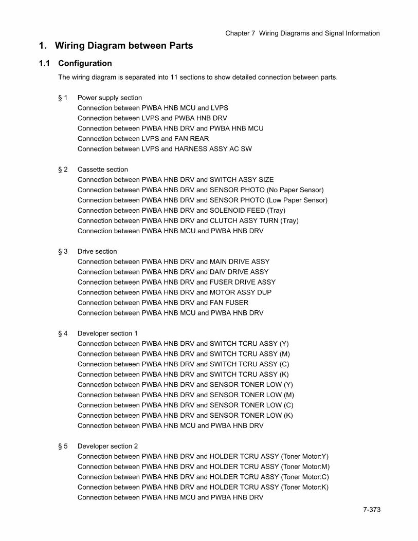
Chapter 7 Wiring Diagrams and Signal Information
1. Wiring Diagram between Parts
1.1 ConfigurationThe wiring diagram is separated into 11 sections to show detailed connection between parts.
§ 1 Power supply sectionConnection between PWBA HNB MCU and LVPSConnection between LVPS and PWBA HNB DRVConnection between PWBA HNB DRV and PWBA HNB MCUConnection between LVPS and FAN REARConnection between LVPS and HARNESS ASSY AC SW
§ 2 Cassette sectionConnection between PWBA HNB DRV and SWITCH ASSY SIZEConnection between PWBA HNB DRV and SENSOR PHOTO (No Paper Sensor)Connection between PWBA HNB DRV and SENSOR PHOTO (Low Paper Sensor)Connection between PWBA HNB DRV and SOLENOID FEED (Tray)Connection between PWBA HNB DRV and CLUTCH ASSY TURN (Tray)Connection between PWBA HNB MCU and PWBA HNB DRV
§ 3 Drive sectionConnection between PWBA HNB DRV and MAIN DRIVE ASSYConnection between PWBA HNB DRV and DAIV DRIVE ASSYConnection between PWBA HNB DRV and FUSER DRIVE ASSYConnection between PWBA HNB DRV and MOTOR ASSY DUPConnection between PWBA HNB DRV and FAN FUSERConnection between PWBA HNB MCU and PWBA HNB DRV
§ 4 Developer section 1Connection between PWBA HNB DRV and SWITCH TCRU ASSY (Y)Connection between PWBA HNB DRV and SWITCH TCRU ASSY (M)Connection between PWBA HNB DRV and SWITCH TCRU ASSY (C)Connection between PWBA HNB DRV and SWITCH TCRU ASSY (K)Connection between PWBA HNB DRV and SENSOR TONER LOW (Y)Connection between PWBA HNB DRV and SENSOR TONER LOW (M)Connection between PWBA HNB DRV and SENSOR TONER LOW (C)Connection between PWBA HNB DRV and SENSOR TONER LOW (K)Connection between PWBA HNB MCU and PWBA HNB DRV
§ 5 Developer section 2Connection between PWBA HNB DRV and HOLDER TCRU ASSY (Toner Motor:Y)Connection between PWBA HNB DRV and HOLDER TCRU ASSY (Toner Motor:M)Connection between PWBA HNB DRV and HOLDER TCRU ASSY (Toner Motor:C)Connection between PWBA HNB DRV and HOLDER TCRU ASSY (Toner Motor:K)Connection between PWBA HNB MCU and PWBA HNB DRV
7-373
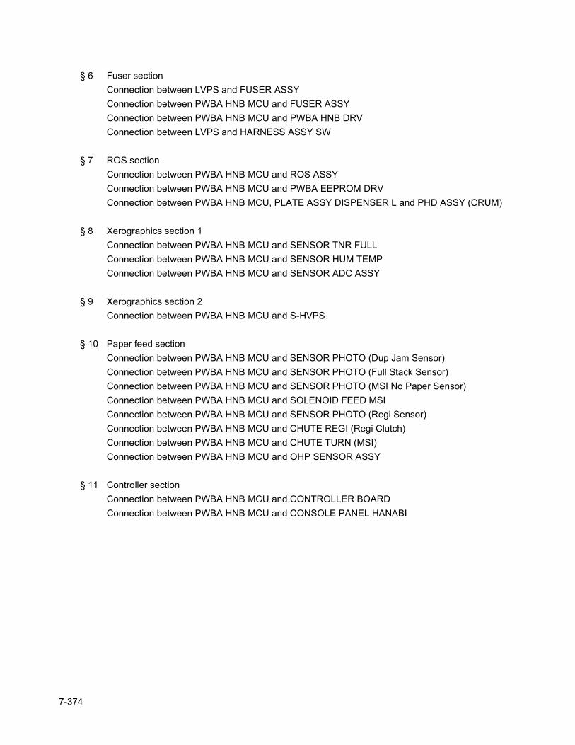
§ 6 Fuser section Connection between LVPS and FUSER ASSYConnection between PWBA HNB MCU and FUSER ASSYConnection between PWBA HNB MCU and PWBA HNB DRVConnection between LVPS and HARNESS ASSY SW
§ 7 ROS section Connection between PWBA HNB MCU and ROS ASSYConnection between PWBA HNB MCU and PWBA EEPROM DRVConnection between PWBA HNB MCU, PLATE ASSY DISPENSER L and PHD ASSY (CRUM)
§ 8 Xerographics section 1Connection between PWBA HNB MCU and SENSOR TNR FULLConnection between PWBA HNB MCU and SENSOR HUM TEMPConnection between PWBA HNB MCU and SENSOR ADC ASSY
§ 9 Xerographics section 2Connection between PWBA HNB MCU and S-HVPS
§ 10 Paper feed section Connection between PWBA HNB MCU and SENSOR PHOTO (Dup Jam Sensor)Connection between PWBA HNB MCU and SENSOR PHOTO (Full Stack Sensor)Connection between PWBA HNB MCU and SENSOR PHOTO (MSI No Paper Sensor)Connection between PWBA HNB MCU and SOLENOID FEED MSIConnection between PWBA HNB MCU and SENSOR PHOTO (Regi Sensor)Connection between PWBA HNB MCU and CHUTE REGI (Regi Clutch)Connection between PWBA HNB MCU and CHUTE TURN (MSI)Connection between PWBA HNB MCU and OHP SENSOR ASSY
§ 11 Controller section Connection between PWBA HNB MCU and CONTROLLER BOARDConnection between PWBA HNB MCU and CONSOLE PANEL HANABI
7-374
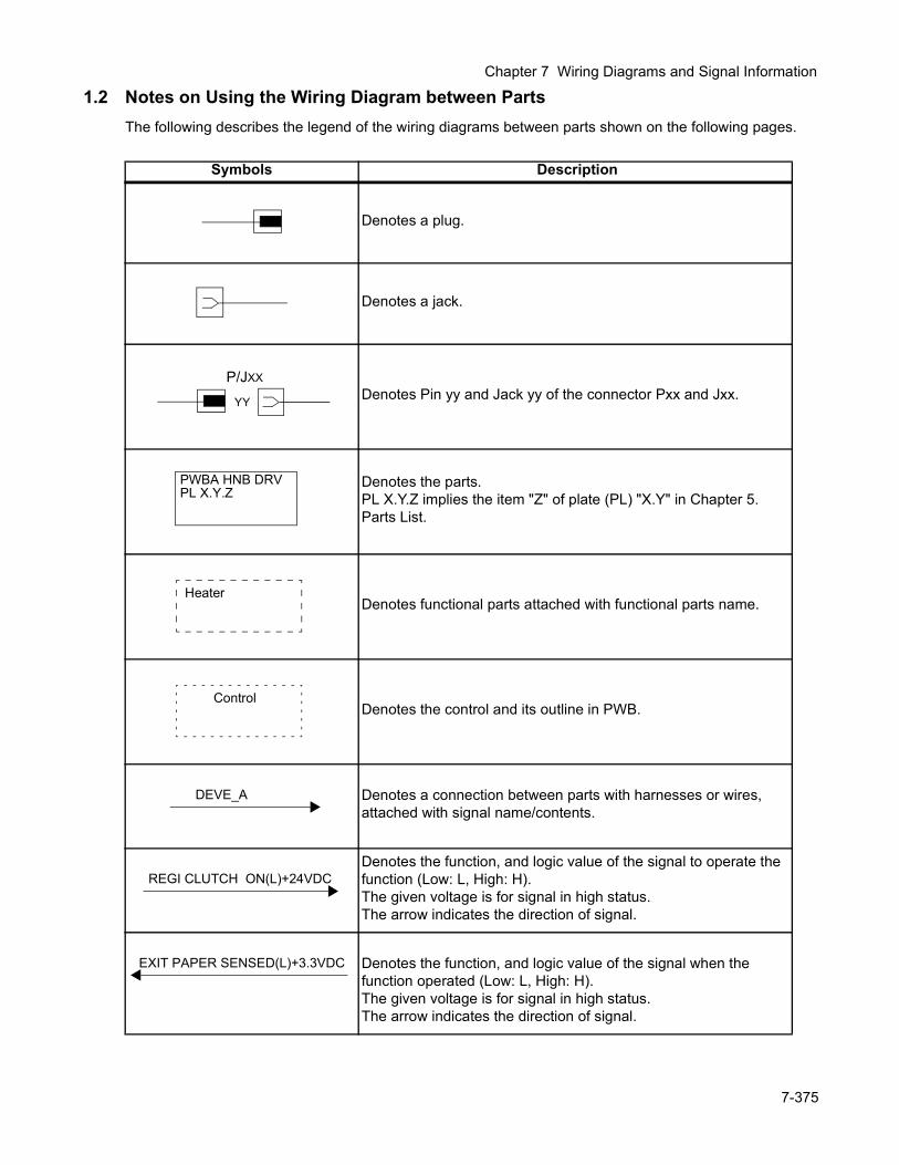
Chapter 7 Wiring Diagrams and Signal Information
1.2 Notes on Using the Wiring Diagram between PartsThe following describes the legend of the wiring diagrams between parts shown on the following pages.
Symbols Description
Denotes a plug.
Denotes a jack.
Denotes Pin yy and Jack yy of the connector Pxx and Jxx.
Denotes the parts.PL X.Y.Z implies the item "Z" of plate (PL) "X.Y" in Chapter 5. Parts List.
Denotes functional parts attached with functional parts name.
Denotes the control and its outline in PWB.
Denotes a connection between parts with harnesses or wires, attached with signal name/contents.
Denotes the function, and logic value of the signal to operate the function (Low: L, High: H).The given voltage is for signal in high status.The arrow indicates the direction of signal.
Denotes the function, and logic value of the signal when the function operated (Low: L, High: H).The given voltage is for signal in high status.The arrow indicates the direction of signal.
P/JXX
YY
PWBA HNB DRVPL X.Y.Z
Heater
Control
DEVE_A
REGI CLUTCH ON(L)+24VDC
EXIT PAPER SENSED(L)+3.3VDC
7-375
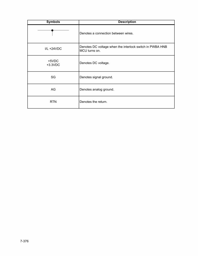
Denotes a connection between wires.
I/L +24VDC Denotes DC voltage when the interlock switch in PWBA HNB MCU turns on.
+5VDC+3.3VDC Denotes DC voltage.
SG Denotes signal ground.
AG Denotes analog ground.
RTN Denotes the return.
Symbols Description
7-376

Chapter 7 Wiring Diagrams and Signal Information
7-377
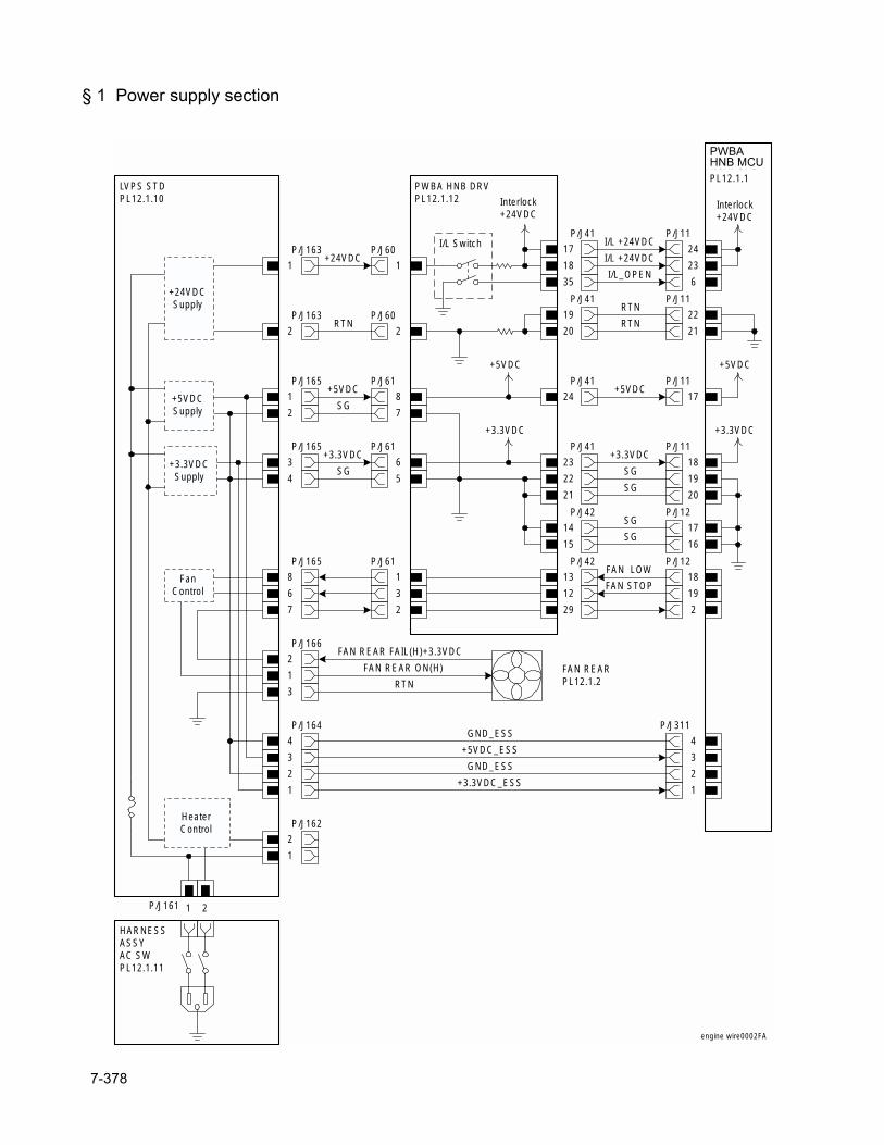
§ 1 Power supply section
LVPS STDPL12.1.10
P/J163
1
P/J163
2
PWBA HNB DRVPL12.1.12
P/J60
1
P/J60
2
+24VDC
RTN
P/J41
17
18
HNB MCUWITH CPUPL12.1.1
P/J11
24
23
I/L +24VDC
I/L +24VDC
35
I/L Switch
6I/L_OPEN
Interlock+24VDC
P/J41
19
20
P/J11
22
21RTN
RTN
P/J165
1
P/J61
8+5VDC
P/J41
24
+5VDC
P/J11
17+5VDC
2 7SG
P/J165
3
P/J61
6+3.3VDC
P/J41
23
+3.3VDC
P/J11
18+3.3VDC
4 5SG
+24VDCSupply
+5VDCSupply
+3.3VDCSupply 22 19
SG
21 20SG
P/J165
8
6
7
P/J61
1
3
2
P/J42
13
12
29
P/J12
18
19
2
FAN LOW
FAN STOP
P/J166
2
1
3
FanControl
FAN REARPL12.1.2
P/J161 1 2
HARNESSASSYAC SWPL12.1.11
HeaterControl P/J162
2
1
P/J164
4
3
2
1
P/J311
4
3
2
1
GND_ESS
+5VDC_ESS
+3.3VDC_ESS
GND_ESS
FAN REAR ON(H)
FAN REAR FAIL(H)+3.3VDC
RTN
Interlock+24VDC
+5VDC
+3.3VDC
engine wire0002FA
P/J42
14
15
P/J12
17
16
SG
SG
PWBAHNB MCU
7-378
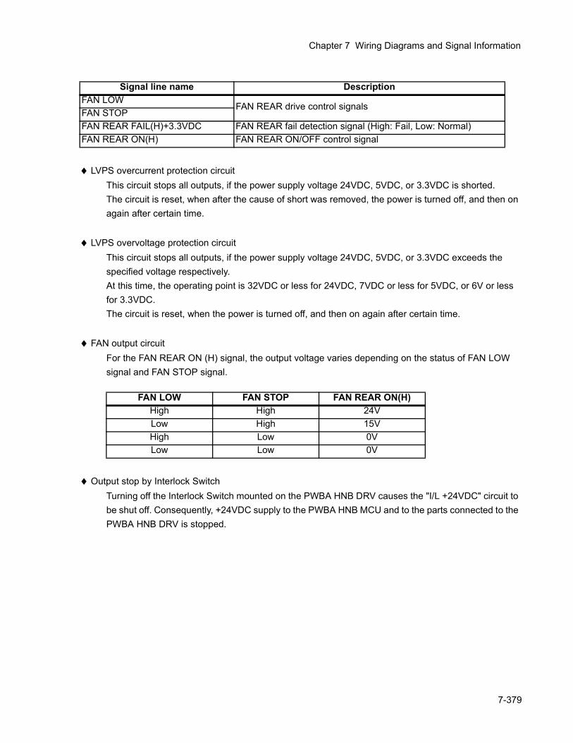
Chapter 7 Wiring Diagrams and Signal Information
♦ LVPS overcurrent protection circuitThis circuit stops all outputs, if the power supply voltage 24VDC, 5VDC, or 3.3VDC is shorted.The circuit is reset, when after the cause of short was removed, the power is turned off, and then on again after certain time.
♦ LVPS overvoltage protection circuitThis circuit stops all outputs, if the power supply voltage 24VDC, 5VDC, or 3.3VDC exceeds the specified voltage respectively.At this time, the operating point is 32VDC or less for 24VDC, 7VDC or less for 5VDC, or 6V or less for 3.3VDC.The circuit is reset, when the power is turned off, and then on again after certain time.
♦ FAN output circuitFor the FAN REAR ON (H) signal, the output voltage varies depending on the status of FAN LOW signal and FAN STOP signal.
♦ Output stop by Interlock SwitchTurning off the Interlock Switch mounted on the PWBA HNB DRV causes the "I/L +24VDC" circuit to be shut off. Consequently, +24VDC supply to the PWBA HNB MCU and to the parts connected to the PWBA HNB DRV is stopped.
Signal line name DescriptionFAN LOW
FAN REAR drive control signalsFAN STOPFAN REAR FAIL(H)+3.3VDC FAN REAR fail detection signal (High: Fail, Low: Normal)FAN REAR ON(H) FAN REAR ON/OFF control signal
FAN LOW FAN STOP FAN REAR ON(H)High High 24VLow High 15VHigh Low 0VLow Low 0V
7-379
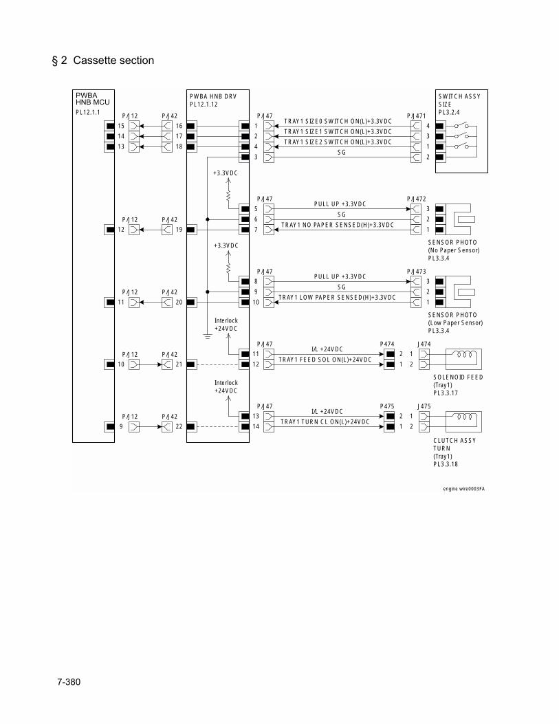
§ 2 Cassette section
P/J472
3
HNB MCUWITH CPUPL12.1.1 P/J12
15
14
13
PWBA HNB DRVPL12.1.12
P/J42
16
17
18
P/J47
1
2
4
3
+3.3VDC
SWITCH ASSYSIZEPL3.2.4
TRAY1 SIZE0 SWITCH ON(L)+3.3VDC
TRAY1 SIZE1 SWITCH ON(L)+3.3VDC
SG
TRAY1 SIZE2 SWITCH ON(L)+3.3VDC
P/J471
4
3
1
2
SENSOR PHOTO(No Paper Sensor)PL3.3.4
2
1
P/J47
5
6
7
PULL UP +3.3VDC
SG
TRAY1 NO PAPER SENSED(H)+3.3VDCP/J42
19
P/J12
12
P/J473
3
SENSOR PHOTO(Low Paper Sensor)PL3.3.4
2
1
P/J47
8
9
10
PULL UP +3.3VDC
SG
TRAY1 LOW PAPER SENSED(H)+3.3VDCP/J42
20
P/J12
11
P/J47
11
12
SOLENOID FEED(Tray1)PL3.3.17
P474
2
J474
1
1 2
I/L +24VDC
TRAY1 FEED SOL ON(L)+24VDCP/J42
21
P/J12
10
P/J47
13
14
CLUTCH ASSYTURN(Tray1)PL3.3.18
P475
2
J475
1
1 2
I/L +24VDC
TRAY1 TURN CL ON(L)+24VDCP/J42
22
P/J12
9
+3.3VDC
Interlock+24VDC
Interlock+24VDC
engine wire0003FA
PWBAHNB MCU
7-380
Chapter 7 Wiring Diagrams and Signal Information
♦ Outline of SWITCH ASSY SIZEThe paper size is determined by a combination of ON/OFF statuses of the upper, middle, and lower switches of SWITCH ASSY SIZE.
Signal line name DescriptionTRAY1 SIZE0 SWITCH ON(L)+3.3VDC ON/OFF detection signal of SWITCH ASSY SIZE upper SW
TRAY1 SIZE1 SWITCH ON(L)+3.3VDC ON/OFF detection signal of SWITCH ASSY SIZE middle SW
TRAY1 SIZE2 SWITCH ON(L)+3.3VDC ON/OFF detection signal of SWITCH ASSY SIZE lower SW
TRAY1 NO PAPER SENSED(L)+3.3VDC
Cassette paper detection signal by SENSOR PHOTO (No Paper Sensor)
TRAY1 LOW PAPER SENSED(L)+3.3VDC
Cassette residual paper detection signal by SENSOR PHOTO (Low Paper Sensor)
TRAY1 FEED SOL ON(L)+24VDC ON/OFF control signal of SOLENOID FEED (Tray 1)TRAY1 TURN CL ON(L)+24VDC ON/OFF control signal of CLUTCH ASSY TURN (Tray 1)
Paper sizeSwitches
Upper Middle Lower
LEGAL14" (SEF) ON ON ON
LEGAL13" (SEF) ON ON OFF
EXECUTIVE (SEF) ON OFF ON
B5 (SEF) ON OFF OFF
A4 (SEF) OFF ON ON
LETTER (SEF) OFF OFF ON
A5 OFF ON ON
No cassette OFF OFF OFF
7-381
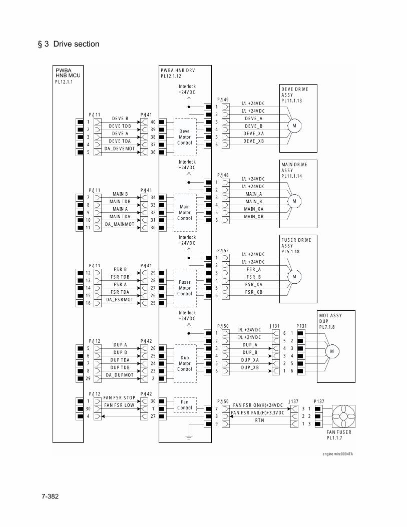
§ 3 Drive section
HNB MCUWITH CPUPL12.1.1
DEVE BP/J11
1
2
3
4
5
PWBA HNB DRVPL12.1.12
P/J41
40
39
38
37
36
DEVE TDB
DEVE A
DEVE TDA
DA_DEVEMOT
P/J49
1
2
3
4
5
6
Interlock+24VDC
DeveMotor
Control
DEVE DRIVEASSYPL11.1.13I/L +24VDC
I/L +24VDC
DEVE_A
DEVE_B
DEVE_XA
DEVE_XB
M
MAIN BP/J11
7
8
9
10
11
P/J41
34
33
32
31
30
MAIN TDB
MAIN A
MAIN TDA
DA_MAINMOT
P/J48
1
2
3
4
5
6
Interlock+24VDC
MAIN DRIVEASSYPL11.1.14I/L +24VDC
I/L +24VDC
MAIN_A
MAIN_B
MAIN_XA
MAIN_XB
M
FSR BP/J11
12
13
14
15
16
P/J41
29
28
27
26
25
FSR TDB
FSR A
FSR TDA
DA_FSRMOT
P/J52
1
2
3
4
5
6
Interlock+24VDC
FUSER DRIVEASSYPL5.1.18I/L +24VDC
I/L +24VDC
FSR_A
FSR_B
FSR_XA
FSR_XB
M
DUP AP/J12
5
6
7
8
29
P/J42
26
25
24
23
2
DUP B
DUP TDA
DUP TDB
DA_DUPMOT
P/J50
1
2
3
4
5
6
Interlock+24VDC
MOT ASSYDUPPL7.1.8I/L +24VDC
I/L +24VDC
DUP_A
DUP_B
DUP_XA
DUP_XB
M
J131
6
5
P131
1
2
4 3
3 4
2 5
1 6
P/J12
1
30
4
P/J42
30
1
27
FAN FSR STOP
FAN FSR LOWP/J50
7
8
9
FanControl
J137
3
2
P137
1
2
1 3
FAN FSR ON(H)+24VDC
FAN FSR FAIL(H)+3.3VDC
RTN
FAN FUSERPL1.1.7
MainMotor
Control
DupMotor
Control
FuserMotor
Control
engine wire0004FA
PWBAHNB MCU
7-382
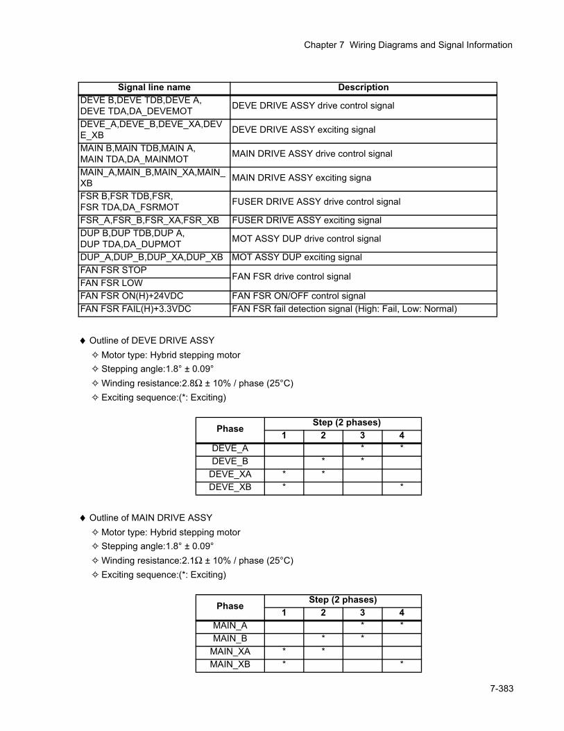
Chapter 7 Wiring Diagrams and Signal Information
♦ Outline of DEVE DRIVE ASSY Motor type: Hybrid stepping motor Stepping angle:1.8° ± 0.09° Winding resistance:2.8Ω ± 10% / phase (25°C) Exciting sequence:(*: Exciting)
♦ Outline of MAIN DRIVE ASSY Motor type: Hybrid stepping motor Stepping angle:1.8° ± 0.09° Winding resistance:2.1Ω ± 10% / phase (25°C) Exciting sequence:(*: Exciting)
Signal line name DescriptionDEVE B,DEVE TDB,DEVE A,DEVE TDA,DA_DEVEMOT DEVE DRIVE ASSY drive control signal
DEVE_A,DEVE_B,DEVE_XA,DEVE_XB DEVE DRIVE ASSY exciting signal
MAIN B,MAIN TDB,MAIN A,MAIN TDA,DA_MAINMOT MAIN DRIVE ASSY drive control signal
MAIN_A,MAIN_B,MAIN_XA,MAIN_XB MAIN DRIVE ASSY exciting signa
FSR B,FSR TDB,FSR,FSR TDA,DA_FSRMOT FUSER DRIVE ASSY drive control signal
FSR_A,FSR_B,FSR_XA,FSR_XB FUSER DRIVE ASSY exciting signalDUP B,DUP TDB,DUP A,DUP TDA,DA_DUPMOT MOT ASSY DUP drive control signal
DUP_A,DUP_B,DUP_XA,DUP_XB MOT ASSY DUP exciting signalFAN FSR STOP
FAN FSR drive control signalFAN FSR LOWFAN FSR ON(H)+24VDC FAN FSR ON/OFF control signalFAN FSR FAIL(H)+3.3VDC FAN FSR fail detection signal (High: Fail, Low: Normal)
Phase Step (2 phases)1 2 3 4
DEVE_A * *DEVE_B * *
DEVE_XA * *DEVE_XB * *
Phase Step (2 phases)1 2 3 4
MAIN_A * *MAIN_B * *
MAIN_XA * *MAIN_XB * *
7-383
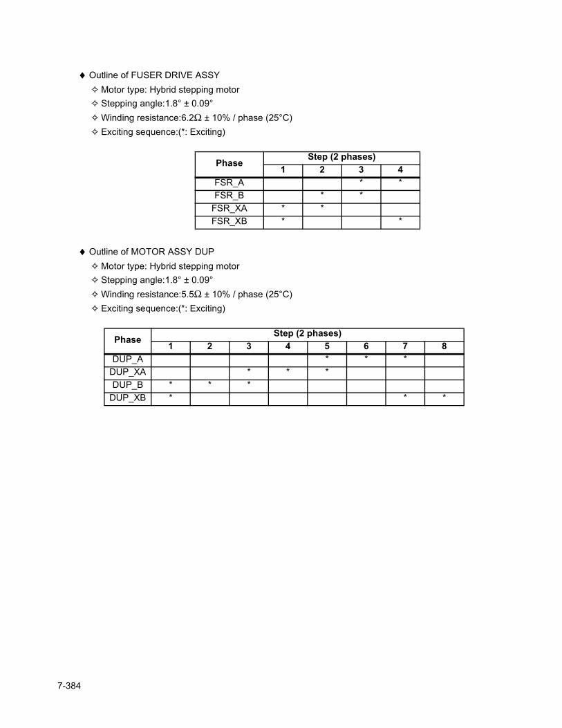
♦ Outline of FUSER DRIVE ASSY Motor type: Hybrid stepping motor Stepping angle:1.8° ± 0.09° Winding resistance:6.2Ω ± 10% / phase (25°C) Exciting sequence:(*: Exciting)
♦ Outline of MOTOR ASSY DUP Motor type: Hybrid stepping motor Stepping angle:1.8° ± 0.09° Winding resistance:5.5Ω ± 10% / phase (25°C) Exciting sequence:(*: Exciting)
Phase Step (2 phases)1 2 3 4
FSR_A * *FSR_B * *
FSR_XA * *FSR_XB * *
Phase Step (2 phases)1 2 3 4 5 6 7 8
DUP_A * * *DUP_XA * * *DUP_B * * *
DUP_XB * * *
7-384

Chapter 7 Wiring Diagrams and Signal Information
Blank Page
7-385
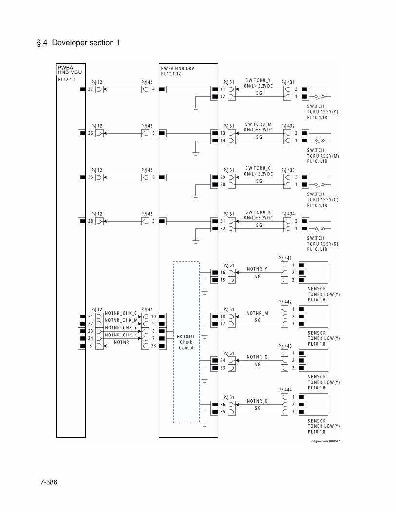
§ 4 Developer section 1
HNB MCUWITH CPUPL12.1.1 P/J12
27
PWBA HNB DRVPL12.1.12
P/J42
4
12 1
SWITCHTCRU ASSY(Y)PL10.1.18
P/J431
2SG
P/J51
11
SW TCRU_YON(L)+3.3VDC
P/J12
26
P/J42
5
14 1
SWITCHTCRU ASSY(M)PL10.1.18
P/J432
2SG
P/J51
13
SW TCRU_MON(L)+3.3VDC
P/J12
25
P/J42
6
30 1
SWITCHTCRU ASSY(C)PL10.1.18
P/J433
2SG
P/J51
29
SW TCRU_CON(L)+3.3VDC
P/J12
28
P/J42
3
32 1
SWITCHTCRU ASSY(K)PL10.1.18
P/J434
2SG
P/J51
31
SW TCRU_KON(L)+3.3VDC
SENSORTONER LOW(Y)PL10.1.8
P/J441
1
2
3
P/J51
16
15SG
NOTNR_Y
P/J12
21
P/J42
10NOTNR_CHK_C
SENSORTONER LOW(Y)PL10.1.8
P/J442
1
2
3
P/J51
18
17SG
NOTNR_M
SENSORTONER LOW(Y)PL10.1.8
P/J443
1
2
3
P/J51
34
33SG
NOTNR_C
SENSORTONER LOW(Y)PL10.1.8
P/J444
1
2
3
P/J51
36
35SG
NOTNR_K
22 9NOTNR_CHK_M
23 8NOTNR_CHK_Y
24 7NOTNR_CHK_K No Toner
CheckControl283
NOTNR
engine wire0005FA
PWBAHNB MCU
7-386
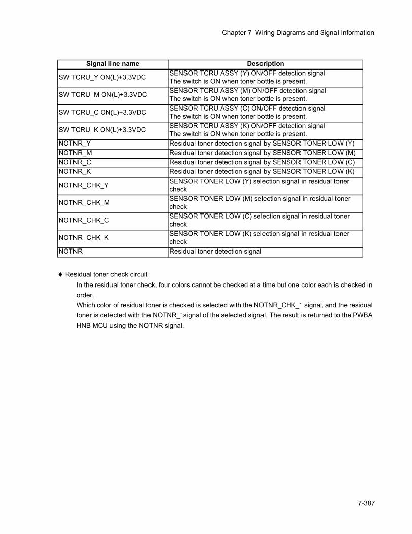
Chapter 7 Wiring Diagrams and Signal Information
♦ Residual toner check circuitIn the residual toner check, four colors cannot be checked at a time but one color each is checked in order.Which color of residual toner is checked is selected with the NOTNR_CHK_* signal, and the residual toner is detected with the NOTNR_* signal of the selected signal. The result is returned to the PWBA HNB MCU using the NOTNR signal.
Signal line name Description
SW TCRU_Y ON(L)+3.3VDC SENSOR TCRU ASSY (Y) ON/OFF detection signalThe switch is ON when toner bottle is present.
SW TCRU_M ON(L)+3.3VDC SENSOR TCRU ASSY (M) ON/OFF detection signalThe switch is ON when toner bottle is present.
SW TCRU_C ON(L)+3.3VDC SENSOR TCRU ASSY (C) ON/OFF detection signalThe switch is ON when toner bottle is present.
SW TCRU_K ON(L)+3.3VDC SENSOR TCRU ASSY (K) ON/OFF detection signalThe switch is ON when toner bottle is present.
NOTNR_Y Residual toner detection signal by SENSOR TONER LOW (Y)NOTNR_M Residual toner detection signal by SENSOR TONER LOW (M)NOTNR_C Residual toner detection signal by SENSOR TONER LOW (C)NOTNR_K Residual toner detection signal by SENSOR TONER LOW (K)
NOTNR_CHK_Y SENSOR TONER LOW (Y) selection signal in residual toner check
NOTNR_CHK_M SENSOR TONER LOW (M) selection signal in residual toner check
NOTNR_CHK_C SENSOR TONER LOW (C) selection signal in residual toner check
NOTNR_CHK_K SENSOR TONER LOW (K) selection signal in residual toner check
NOTNR Residual toner detection signal
7-387
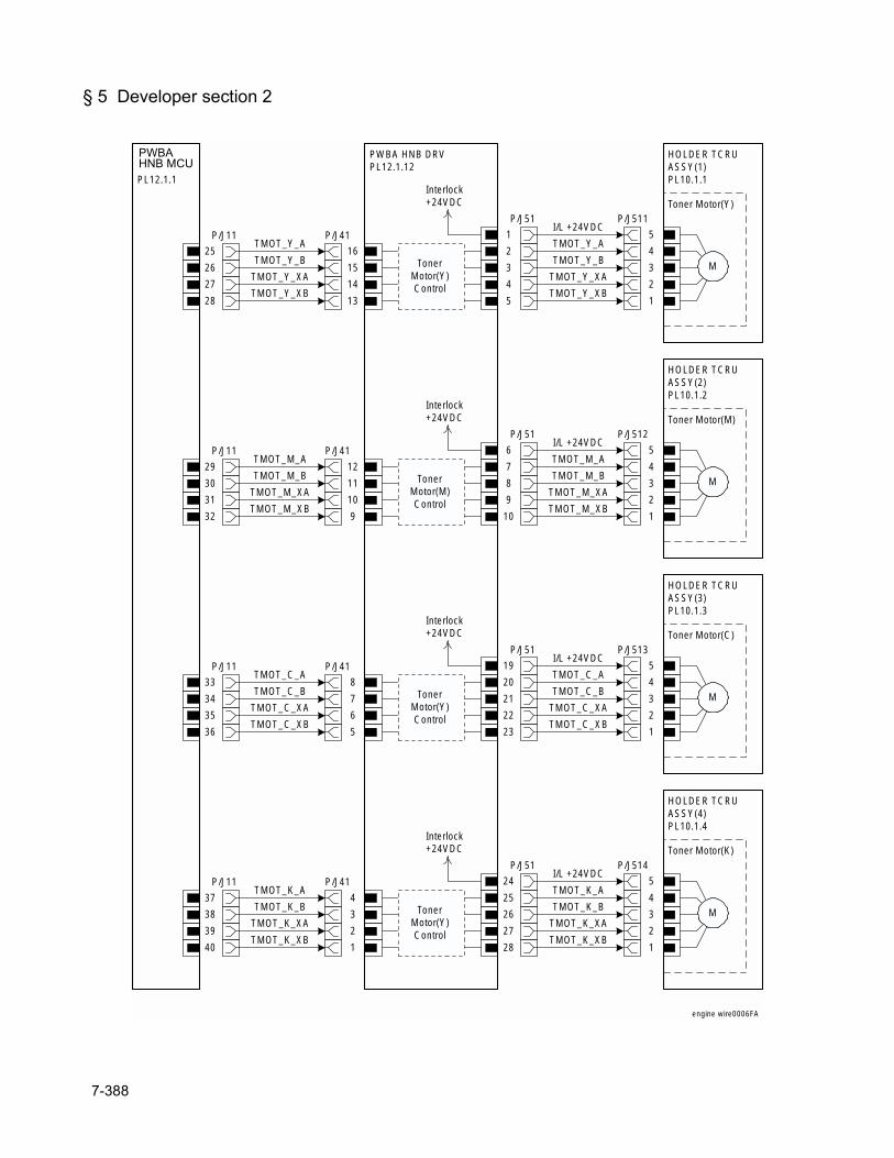
§ 5 Developer section 2
HNB MCUWITH CPUPL12.1.1
P/J11
25
26
27
28
PWBA HNB DRVPL12.1.12
P/J41
16
15
14
13
P/J51
1
2
3
4
5
Interlock+24VDC
TonerMotor(Y)Control
HOLDER TCRUASSY(1)PL10.1.1
I/L +24VDC
TMOT_Y_A
TMOT_Y_B
TMOT_Y_XA
TMOT_Y_XB
P/J511
5
4
3
2
1
M
TMOT_Y_A
TMOT_Y_B
TMOT_Y_XA
TMOT_Y_XB
P/J11
29
30
31
32
P/J41
12
11
10
9
P/J51
6
7
8
9
10
Interlock+24VDC
TonerMotor(M)Control
HOLDER TCRUASSY(2)PL10.1.2
I/L +24VDC
TMOT_M_A
TMOT_M_B
TMOT_M_XA
TMOT_M_XB
P/J512
5
4
3
2
1
M
TMOT_M_A
TMOT_M_B
TMOT_M_XA
TMOT_M_XB
P/J11
33
34
35
36
P/J41
8
7
6
5
P/J51
19
20
21
22
23
Interlock+24VDC
TonerMotor(Y)Control
HOLDER TCRUASSY(3)PL10.1.3
I/L +24VDC
TMOT_C_A
TMOT_C_B
TMOT_C_XA
TMOT_C_XB
P/J513
5
4
3
2
1
M
TMOT_C_A
TMOT_C_B
TMOT_C_XA
TMOT_C_XB
P/J11
37
38
39
40
P/J41
4
3
2
1
P/J51
24
25
26
27
28
Interlock+24VDC
TonerMotor(Y)Control
HOLDER TCRUASSY(4)PL10.1.4
I/L +24VDC
TMOT_K_A
TMOT_K_B
TMOT_K_XA
TMOT_K_XB
P/J514
5
4
3
2
1
M
TMOT_K_A
TMOT_K_B
TMOT_K_XA
TMOT_K_XB
Toner Motor(Y)
Toner Motor(M)
Toner Motor(C)
Toner Motor(K)
engine wire0006FA
PWBAHNB MCU
7-388
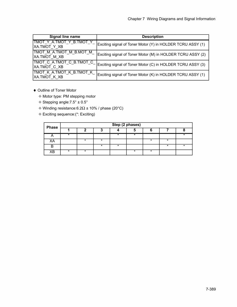
Chapter 7 Wiring Diagrams and Signal Information
♦ Outline of Toner Motor Motor type: PM stepping motor Stepping angle:7.5° ± 0.5° Winding resistance:6.2Ω ± 10% / phase (20°C) Exciting sequence:(*: Exciting)
Signal line name DescriptionTMOT_Y_A.TMOT_Y_B.TMOT_Y_XA.TMOT_Y_XB Exciting signal of Toner Motor (Y) in HOLDER TCRU ASSY (1)
TMOT_M_A.TMOT_M_B.MOT_M_XA.TMOT_M_XB Exciting signal of Toner Motor (M) in HOLDER TCRU ASSY (2)
TMOT_C_A.TMOT_C_B.TMOT_C_XA.TMOT_C_XB Exciting signal of Toner Motor (C) in HOLDER TCRU ASSY (3)
TMOT_K_A.TMOT_K_B.TMOT_K_XA.TMOT_K_XB Exciting signal of Toner Motor (K) in HOLDER TCRU ASSY (1)
Phase Step (2 phases)1 2 3 4 5 6 7 8
A * * * *XA * * * *B * * * *
XB * * * *
7-389
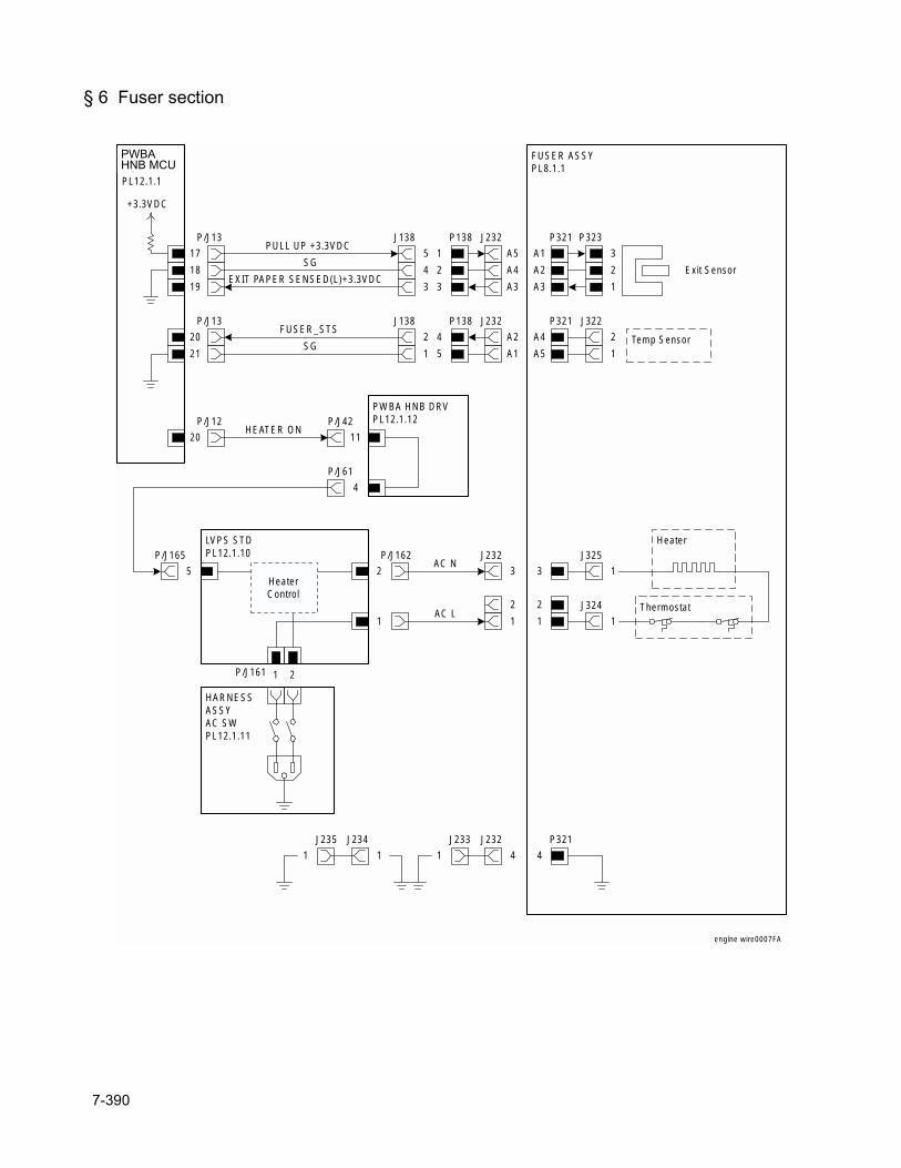
§ 6 Fuser section
P/J161 1 2
HARNESSASSYAC SWPL12.1.11
HeaterControl
P/J162
2
1
LVPS STDPL12.1.10
FUSER ASSYPL8.1.1
J232
4
J232
3
2
1
P321
4
3
2
1
AC N
AC LJ324
1
J325
1
Heater
Thermostat
HNB MCUWITH CPUPL12.1.1
P/J13
17
J138
5
4
P138
1
2
J232
A5
A4
A3
J232
A2
P321
A1
A2
A3
P321
A4
18
19
P/J13
20
21
3 3
J138
2
P138
4
1 5 A1 A5
Exit Sensor
P323
3
2
1
PULL UP +3.3VDC
SG
EXIT PAPER SENSED(L)+3.3VDC
Temp Sensor
J322
2
1SG
FUSER_STS
+3.3VDC
J233
1
J235
1
J234
1
P/J12
20
PWBA HNB DRVPL12.1.12P/J42
11HEATER ON
P/J165
5
P/J61
4
engine wire0007FA
PWBAHNB MCU
7-390
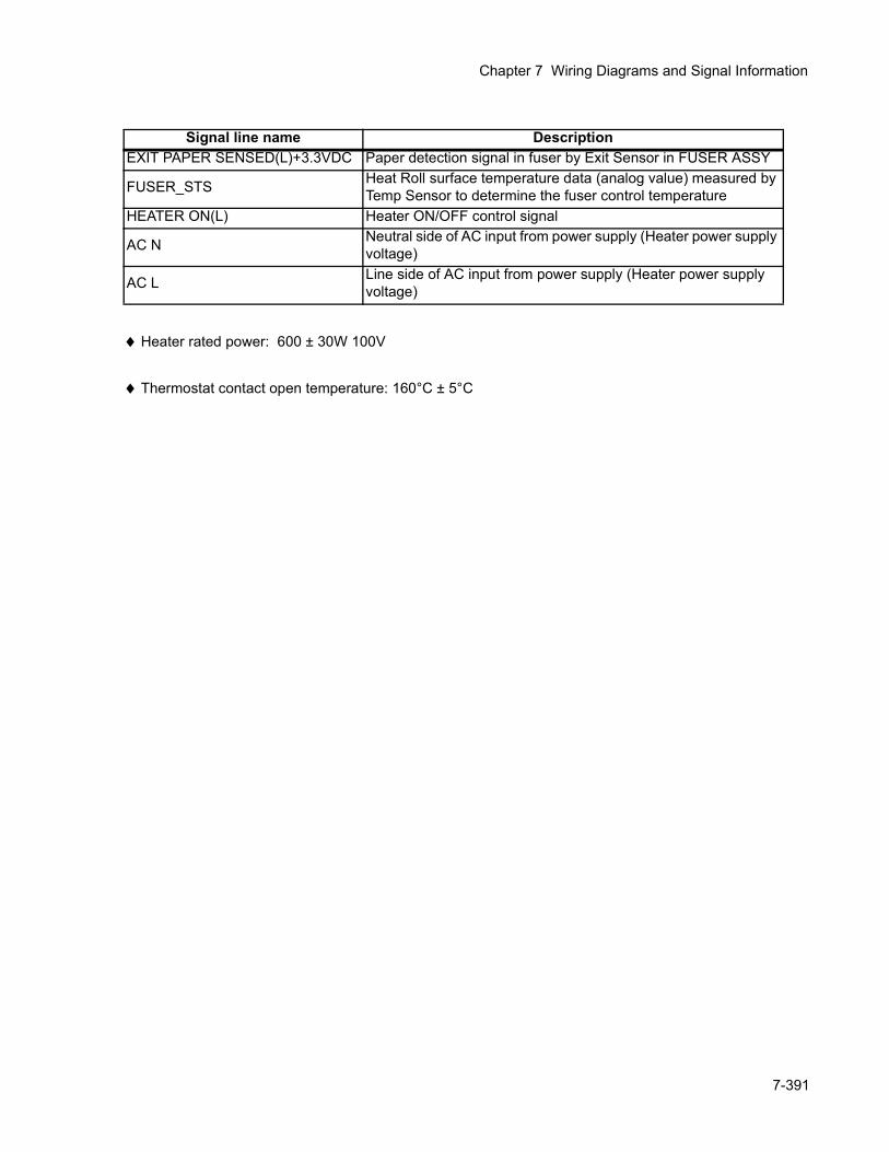
Chapter 7 Wiring Diagrams and Signal Information
♦ Heater rated power: 600 ± 30W 100V
♦ Thermostat contact open temperature: 160°C ± 5°C
Signal line name DescriptionEXIT PAPER SENSED(L)+3.3VDC Paper detection signal in fuser by Exit Sensor in FUSER ASSY
FUSER_STS Heat Roll surface temperature data (analog value) measured by Temp Sensor to determine the fuser control temperature
HEATER ON(L) Heater ON/OFF control signal
AC N Neutral side of AC input from power supply (Heater power supply voltage)
AC L Line side of AC input from power supply (Heater power supply voltage)
7-391
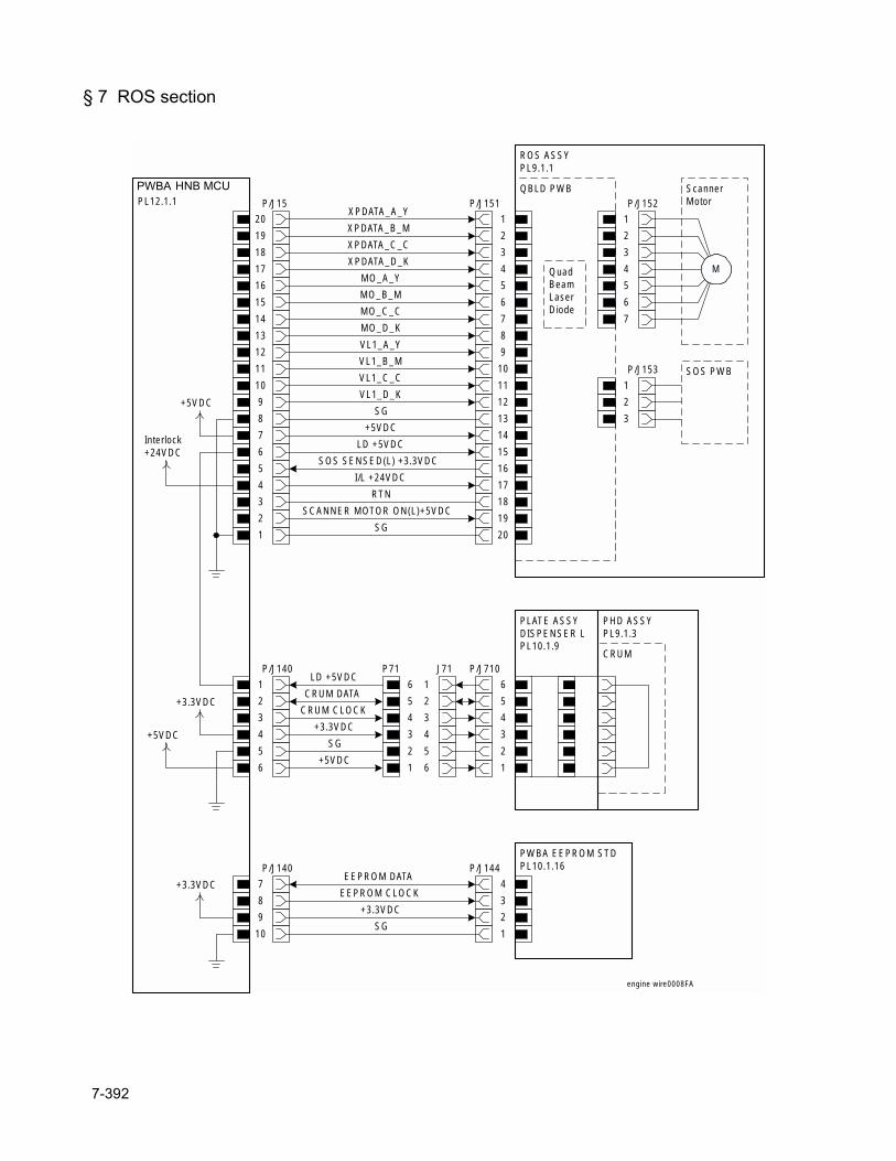
§ 7 ROS section
HNB MCU WITH CPUPL12.1.1
ROS ASSYPL9.1.1
1
2
3
4
5
6
7
8
9
10
11
12
13
14
15
16
17
18
19
P/J15
20
20
19
18
17
16
15
14
13
12
11
10
9
8
7
6
5
4
3
2
P/J151
1
SG
SCANNER MOTOR ON(L)+5VDC
RTN
I/L +24VDC
SOS SENSED(L) +3.3VDC
LD +5VDC
+5VDC
SG
VL1_D_K
VL1_C_C
VL1_B_M
VL1_A_Y
MO_D_K
MO_C_C
MO_B_M
MO_A_Y
XPDATA_D_K
XPDATA_C_C
XPDATA_B_M
XPDATA_A_Y
+5VDC
Interlock+24VDC
4
3
2
P/J140
1
5
6
10
9
8
P/J140
7
QBLD PWBP/J152
1
2
3
4
5
6
7
ScannerMotor
M
P/J153
1
2
3
SOS PWB
PLATE ASSYDISPENSER LPL10.1.9
CRUMP71
6
5
4
3
2
1
J71
1
2
3
4
5
6
3
4
5
P/J710
6
2
1
PWBA EEPROM STDPL10.1.16
1
2
3
P/J144
4
LD +5VDC
CRUM DATA
CRUM CLOCK
+3.3VDC
SG
+5VDC
EEPROM DATA
EEPROM CLOCK
+3.3VDC
SG
+3.3VDC
engine wire0008FA
QuadBeamLaserDiode
+3.3VDC
+5VDC
PHD ASSYPL9.1.3
PWBA HNB MCU
7-392
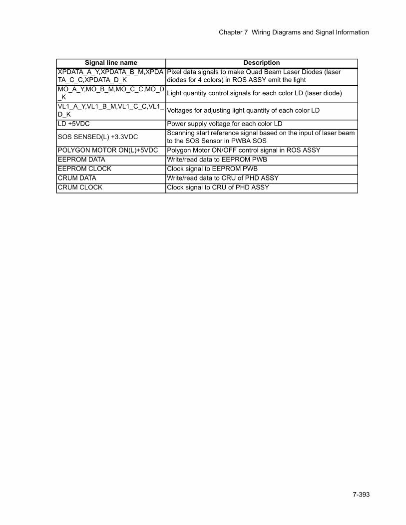
Chapter 7 Wiring Diagrams and Signal Information
Signal line name DescriptionXPDATA_A_Y,XPDATA_B_M,XPDATA_C_C,XPDATA_D_K
Pixel data signals to make Quad Beam Laser Diodes (laser diodes for 4 colors) in ROS ASSY emit the light
MO_A_Y,MO_B_M,MO_C_C,MO_D_K Light quantity control signals for each color LD (laser diode)
VL1_A_Y,VL1_B_M,VL1_C_C,VL1_D_K Voltages for adjusting light quantity of each color LD
LD +5VDC Power supply voltage for each color LD
SOS SENSED(L) +3.3VDC Scanning start reference signal based on the input of laser beam to the SOS Sensor in PWBA SOS
POLYGON MOTOR ON(L)+5VDC Polygon Motor ON/OFF control signal in ROS ASSYEEPROM DATA Write/read data to EEPROM PWB EEPROM CLOCK Clock signal to EEPROM PWBCRUM DATA Write/read data to CRU of PHD ASSYCRUM CLOCK Clock signal to CRU of PHD ASSY
7-393
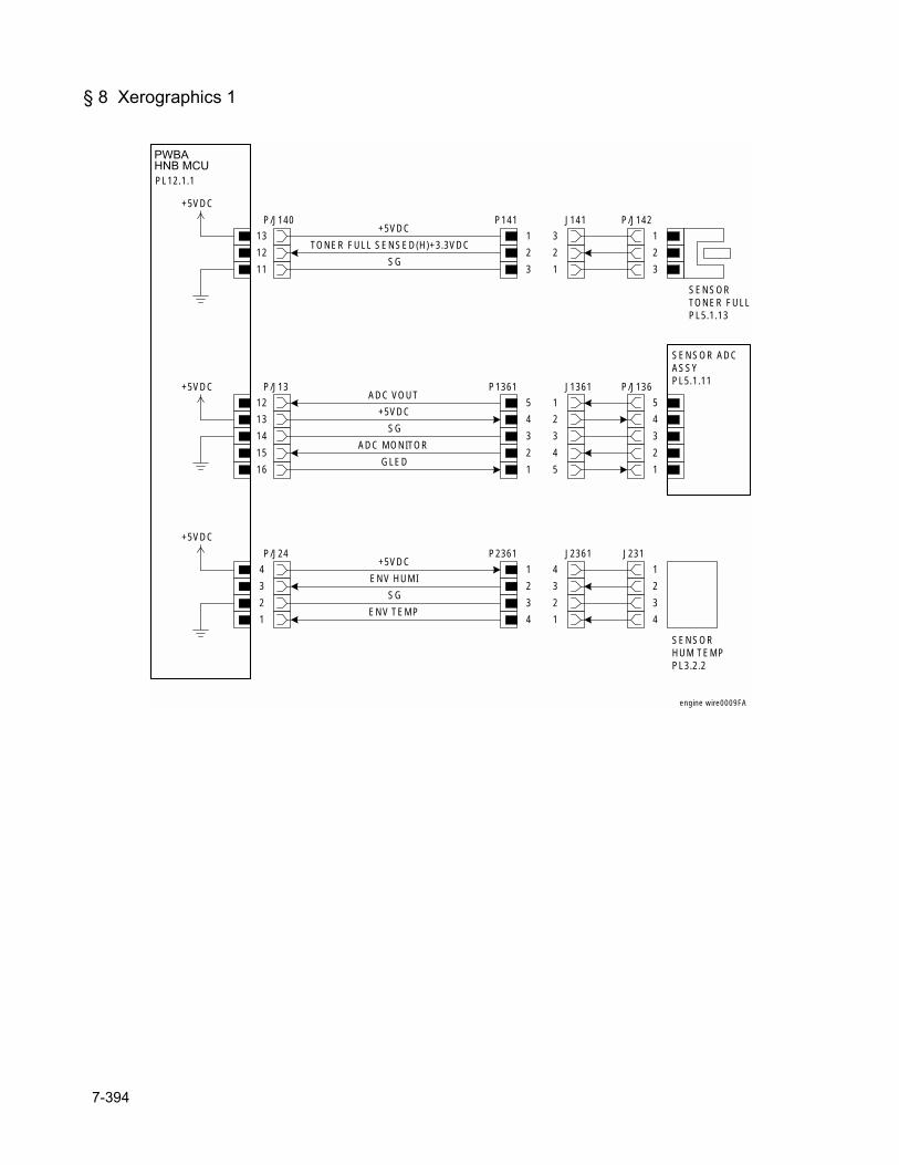
§ 8 Xerographics 1
HNB MCU WITHCPUPL12.1.1
P/J140
13
12
11
P141
1
J141
3
P/J142
1
2
3
2 2
3 1
SENSORTONER FULLPL5.1.13
+5VDC
TONER FULL SENSED(H)+3.3VDC
SG
P/J13
12
13
14
15
16
P1361
5
J1361
1
4 2
3 3
2 4
1 5
P/J136
5
4
3
2
1
SENSOR ADCASSYPL5.1.11
ADC VOUT
+5VDC
SG
ADC MONITOR
GLED
+5VDC
+5VDC
SENSORHUM TEMPPL3.2.2
J231
1
2
3
4
P2361
1
J2361
4
2 3
3 2
4 1
P/J24
4
3
2
1
+5VDC
+5VDC
ENV HUMI
SG
ENV TEMP
engine wire0009FA
PWBAHNB MCU
7-394
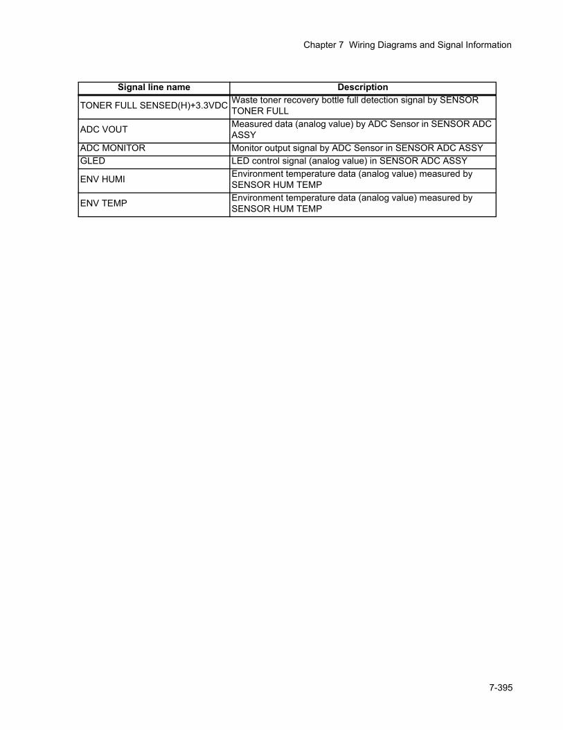
Chapter 7 Wiring Diagrams and Signal Information
Signal line name Description
TONER FULL SENSED(H)+3.3VDC Waste toner recovery bottle full detection signal by SENSOR TONER FULL
ADC VOUT Measured data (analog value) by ADC Sensor in SENSOR ADC ASSY
ADC MONITOR Monitor output signal by ADC Sensor in SENSOR ADC ASSYGLED LED control signal (analog value) in SENSOR ADC ASSY
ENV HUMI Environment temperature data (analog value) measured by SENSOR HUM TEMP
ENV TEMP Environment temperature data (analog value) measured by SENSOR HUM TEMP
7-395
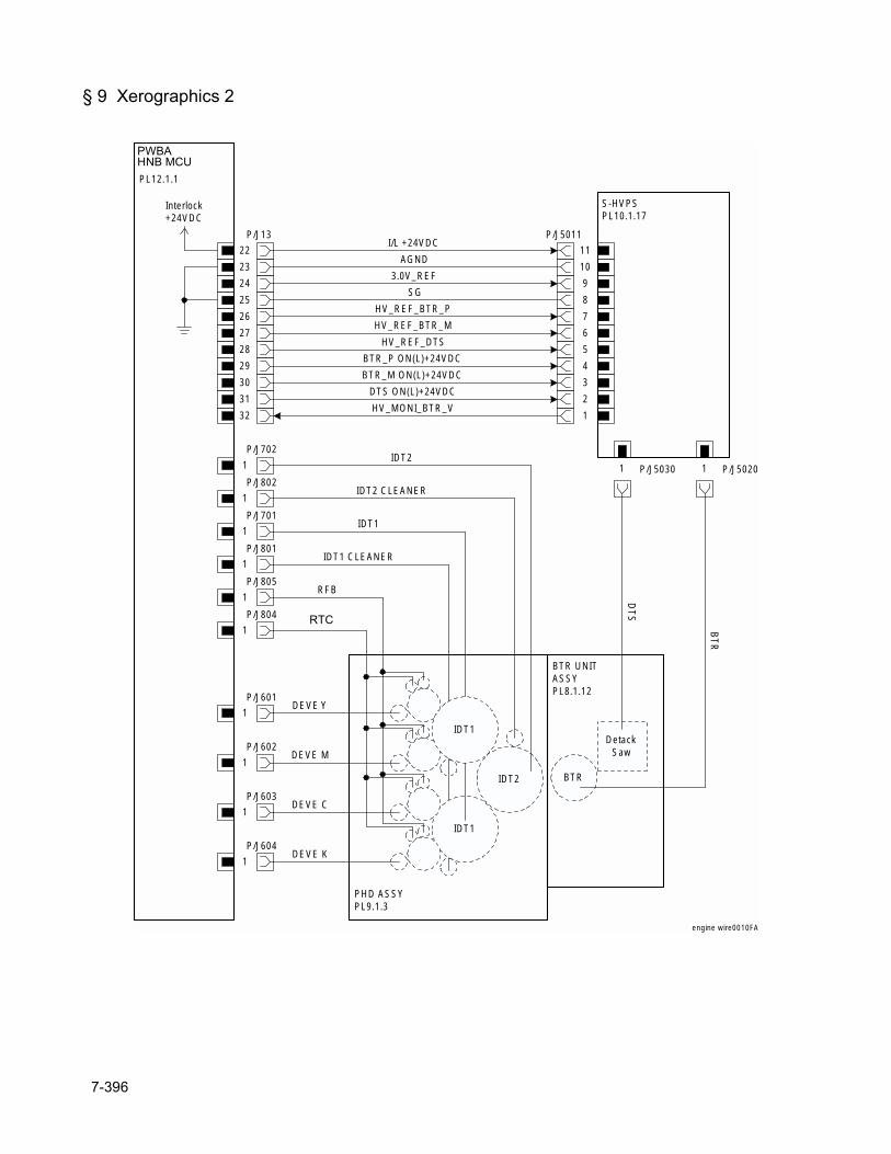
§ 9 Xerographics 2
HNB MCU WITHCPUPL12.1.1
P/J13
22
23
24
25
26
27
28
29
30
31
32
S-HVPSPL10.1.17
P/J5011
11
10
9
8
7
6
5
4
3
2
1
I/L +24VDC
AGND
3.0V_REF
SG
HV_REF_BTR_P
HV_REF_BTR_M
HV_REF_DTS
BTR_P ON(L)+24VDC
BTR_M ON(L)+24VDC
DTS ON(L)+24VDC
HV_MONI_BTR_V
P/J702
1
P/J802
1
IDT2
IDT2 CLEANER
HTC
P/J701
1
P/J801
1
IDT1
IDT1 CLEANER
P/J805
1
IDT1
IDT2
RFB
PHD ASSYPL9.1.3
P/J804
1
P/J601
1
P/J602
1
P/J603
1
P/J604
1
DEVE M
DEVE C
DEVE K
DEVE Y
BTR UNITASSYPL8.1.12
BTR
P/J50301 P/J50201
DetackSaw
DTS
BTR
IDT1
Interlock+24VDC
engine wire0010FA
PWBAHNB MCU
RTC
7-396
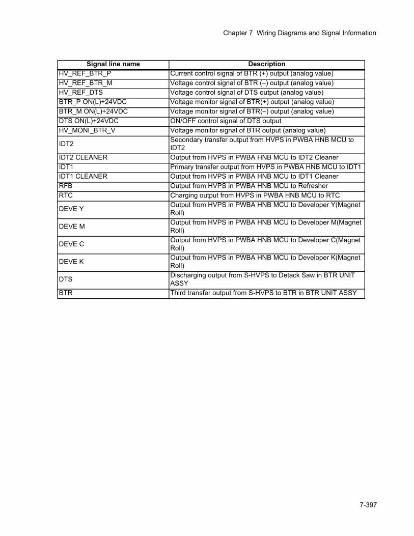
Chapter 7 Wiring Diagrams and Signal Information
Signal line name DescriptionHV_REF_BTR_P Current control signal of BTR (+) output (analog value)HV_REF_BTR_M Voltage control signal of BTR (–) output (analog value)HV_REF_DTS Voltage control signal of DTS output (analog value)BTR_P ON(L)+24VDC Voltage monitor signal of BTR(+) output (analog value)BTR_M ON(L)+24VDC Voltage monitor signal of BTR(–) output (analog value)DTS ON(L)+24VDC ON/OFF control signal of DTS outputHV_MONI_BTR_V Voltage monitor signal of BTR output (analog value)
IDT2 Secondary transfer output from HVPS in PWBA HNB MCU to IDT2
IDT2 CLEANER Output from HVPS in PWBA HNB MCU to IDT2 CleanerIDT1 Primary transfer output from HVPS in PWBA HNB MCU to IDT1IDT1 CLEANER Output from HVPS in PWBA HNB MCU to IDT1 CleanerRFB Output from HVPS in PWBA HNB MCU to RefresherRTC Charging output from HVPS in PWBA HNB MCU to RTC
DEVE Y Output from HVPS in PWBA HNB MCU to Developer Y(Magnet Roll)
DEVE M Output from HVPS in PWBA HNB MCU to Developer M(Magnet Roll)
DEVE C Output from HVPS in PWBA HNB MCU to Developer C(Magnet Roll)
DEVE K Output from HVPS in PWBA HNB MCU to Developer K(Magnet Roll)
DTS Discharging output from S-HVPS to Detack Saw in BTR UNIT ASSY
BTR Third transfer output from S-HVPS to BTR in BTR UNIT ASSY
7-397
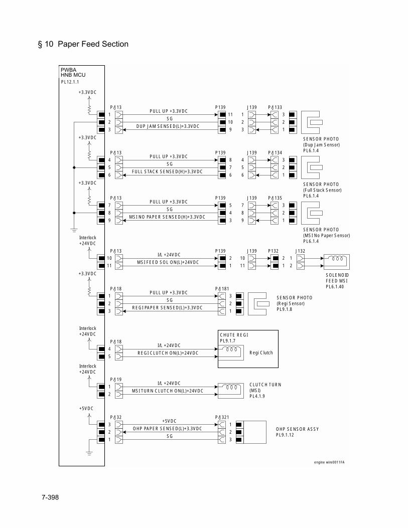
§ 10 Paper Feed Section
HNB MCU WITHCPUPL12.1.1
P/J13
1
2
3
P139
11
J139
1
P/J133
3
2
1
10 2
9 3
SENSOR PHOTO(Dup Jam Sensor)PL6.1.4
PULL UP +3.3VDC
+3.3VDC
SG
DUP JAM SENSED(L)+3.3VDC
P/J13
4
5
6
P139
8
J139
4
P/J134
3
2
1
7 5
6 6
SENSOR PHOTO(Full Stack Sensor)PL6.1.4
PULL UP +3.3VDC
SG
FULL STACK SENSED(H)+3.3VDC
+3.3VDC
P/J13
7
8
9
P139
5
J139
7
P/J135
3
2
1
4 8
3 9
SENSOR PHOTO(MSI No Paper Sensor)PL6.1.4
PULL UP +3.3VDC
SG
MSI NO PAPER SENSED(H)+3.3VDC
+3.3VDC
P/J13
10
11
P139
2
J139
10
1 11
P132
2
J132
1
1 2
SOLENOIDFEED MSIPL6.1.40
I/L +24VDC
MSI FEED SOL ON(L)+24VDC
Interlock+24VDC
P/J18
1
2
3
PULL UP +3.3VDC
+3.3VDC
SG
REGI PAPER SENSED(L)+3.3VDC
P/J181
3
2
1
SENSOR PHOTO(Regi Sensor)PL9.1.8
P/J18
4
5
I/L +24VDC
REGI CLUTCH ON(L)+24VDC
Interlock+24VDC
Regi Clutch
CHUTE REGIPL9.1.7
P/J19
1
2
I/L +24VDC
MSI TURN CLUTCH ON(L)+24VDCCLUTCH TURN(MSI)PL4.1.9
Interlock+24VDC
P/J32
3
2
1
+5VDC
OHP PAPER SENSED(L)+3.3VDC
SG
OHP SENSOR ASSYPL9.1.12
P/J321
1
2
3
+5VDC
engine wire0011FA
PWBAHNB MCU
7-398
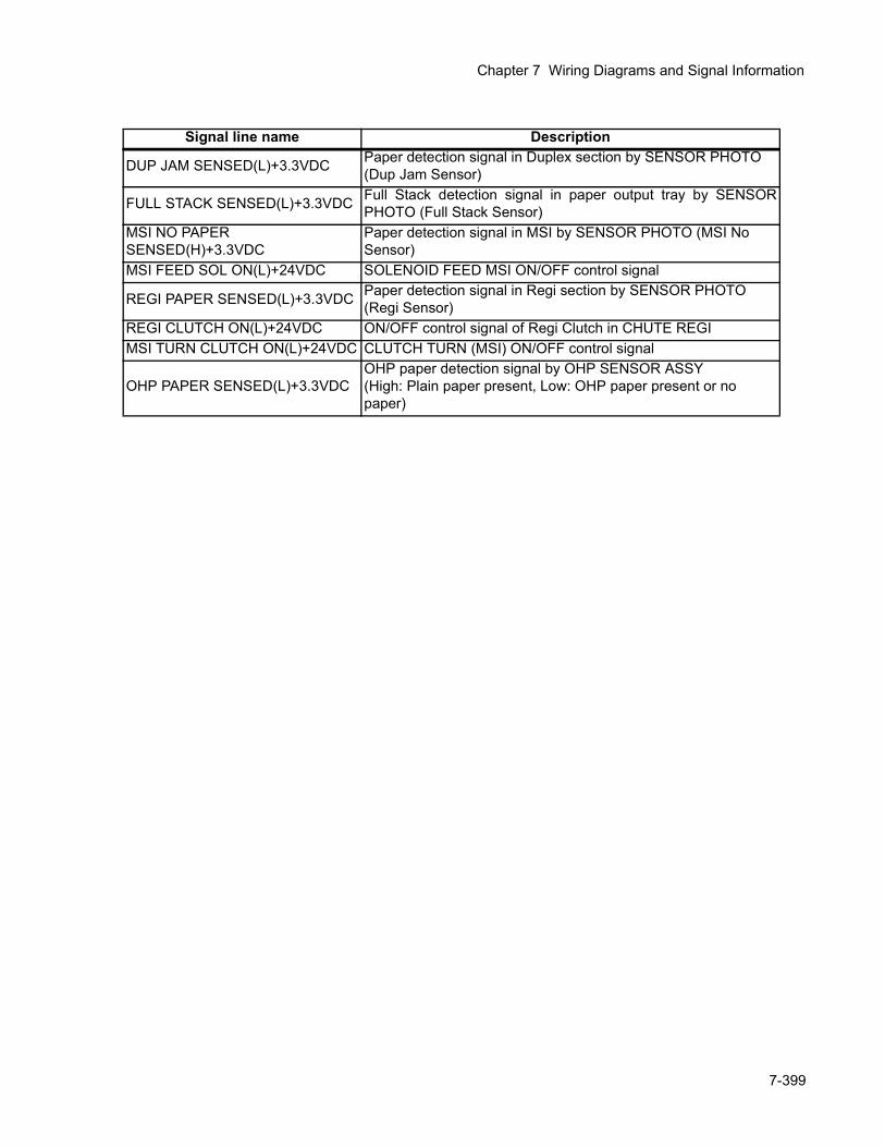
Chapter 7 Wiring Diagrams and Signal Information
Signal line name Description
DUP JAM SENSED(L)+3.3VDC Paper detection signal in Duplex section by SENSOR PHOTO (Dup Jam Sensor)
FULL STACK SENSED(L)+3.3VDC Full Stack detection signal in paper output tray by SENSORPHOTO (Full Stack Sensor)
MSI NO PAPER SENSED(H)+3.3VDC
Paper detection signal in MSI by SENSOR PHOTO (MSI No Sensor)
MSI FEED SOL ON(L)+24VDC SOLENOID FEED MSI ON/OFF control signal
REGI PAPER SENSED(L)+3.3VDC Paper detection signal in Regi section by SENSOR PHOTO (Regi Sensor)
REGI CLUTCH ON(L)+24VDC ON/OFF control signal of Regi Clutch in CHUTE REGIMSI TURN CLUTCH ON(L)+24VDC CLUTCH TURN (MSI) ON/OFF control signal
OHP PAPER SENSED(L)+3.3VDCOHP paper detection signal by OHP SENSOR ASSY(High: Plain paper present, Low: OHP paper present or no paper)
7-399
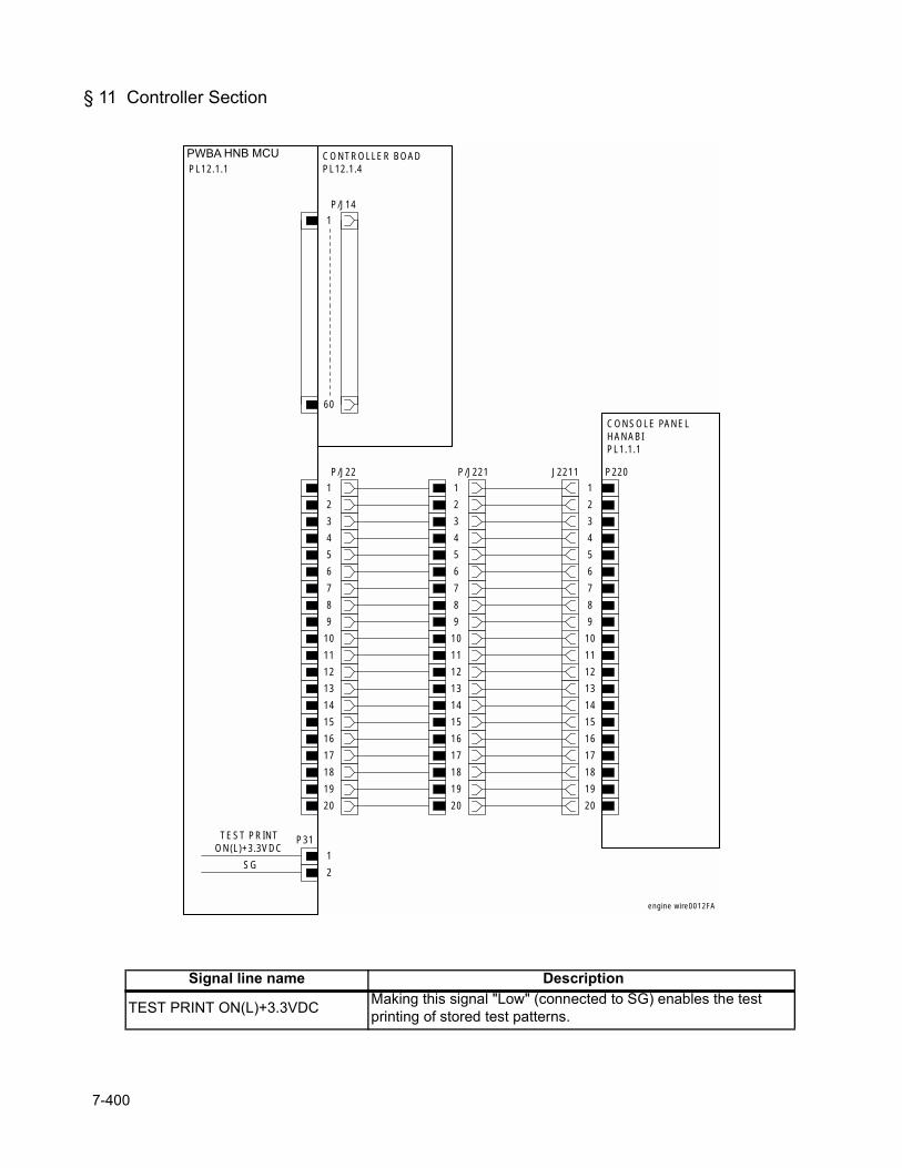
§ 11 Controller Section
Signal line name Description
TEST PRINT ON(L)+3.3VDC Making this signal "Low" (connected to SG) enables the test printing of stored test patterns.
HNB MCU WITH CPUPL12.1.1
P/J14
1
60
CONTROLLER BOADPL12.1.4
P/J22
1
2
3
4
5
6
7
8
9
10
11
12
13
14
15
16
17
18
19
20
P/J221
1
2
3
4
5
6
7
8
9
10
11
12
13
14
15
16
17
18
19
20
P220
1
2
3
4
5
6
7
8
9
10
11
12
13
14
15
16
17
18
19
20
J2211
CONSOLE PANELHANABIPL1.1.1
P31
1
2
TEST PRINTON(L)+3.3VDC
SG
engine wire0012FA
PWBA HNB MCU
7-400

Chapter 8 Printer Specifications

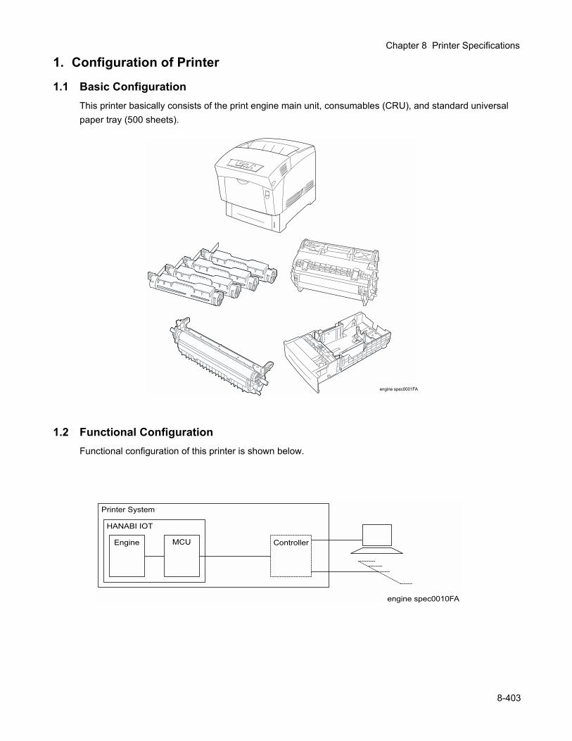
Chapter 8 Printer Specifications
1. Configuration of Printer
1.1 Basic ConfigurationThis printer basically consists of the print engine main unit, consumables (CRU), and standard universal paper tray (500 sheets).
1.2 Functional ConfigurationFunctional configuration of this printer is shown below.
8-403
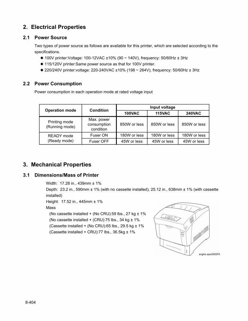
2. Electrical Properties
2.1 Power SourceTwo types of power source as follows are available for this printer, which are selected according to the specifications.
100V printer:Voltage: 100-12VAC ±10% (90 ~ 140V), frequency: 50/60Hz ± 3Hz 115/120V printer:Same power source as that for 100V printer. 220/240V printer:voltage: 220-240VAC ±10% (198 ~ 264V), frequency: 50/60Hz ± 3Hz
2.2 Power ConsumptionPower consumption in each operation mode at rated voltage input
3. Mechanical Properties
3.1 Dimensions/Mass of PrinterWidth: 17.28 in., 439mm ± 1%Depth: 23.2 in., 590mm ± 1% (with no cassette installed), 25.12 in., 638mm ± 1% (with cassette installed)Height: 17.52 in., 445mm ± 1%Mass
(No cassette installed + (No CRU):59 lbs., 27 kg ± 1%(No cassette installed + (CRU):75 lbs., 34 kg ± 1%(Cassette installed + (No CRU):65 lbs., 29.5 kg ± 1%(Cassette installed + CRU):77 lbs., 36.5kg ± 1%
Operation mode ConditionInput voltage
100VAC 115VAC 240VAC
Printing mode(Running mode)
Max. powerconsumption
condition850W or less 850W or less 850W or less
READY mode(Ready mode)
Fuser ON 180W or less 180W or less 180W or lessFuser OFF 45W or less 45W or less 45W or less
8-404
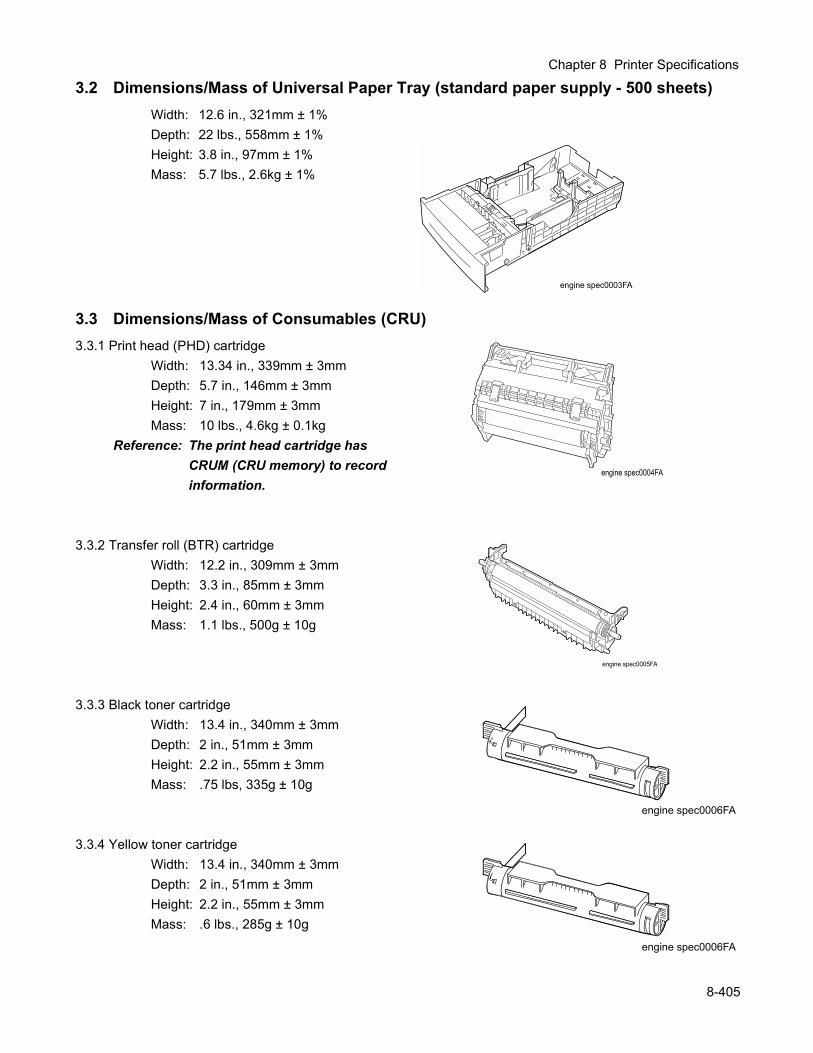
Chapter 8 Printer Specifications
3.2 Dimensions/Mass of Universal Paper Tray (standard paper supply - 500 sheets)Width: 12.6 in., 321mm ± 1%Depth: 22 lbs., 558mm ± 1%Height: 3.8 in., 97mm ± 1%Mass: 5.7 lbs., 2.6kg ± 1%
3.3 Dimensions/Mass of Consumables (CRU)3.3.1 Print head (PHD) cartridge
Width: 13.34 in., 339mm ± 3mmDepth: 5.7 in., 146mm ± 3mmHeight: 7 in., 179mm ± 3mmMass: 10 lbs., 4.6kg ± 0.1kg
Reference: The print head cartridge has CRUM (CRU memory) to record information.
3.3.2 Transfer roll (BTR) cartridgeWidth: 12.2 in., 309mm ± 3mmDepth: 3.3 in., 85mm ± 3mmHeight: 2.4 in., 60mm ± 3mmMass: 1.1 lbs., 500g ± 10g
3.3.3 Black toner cartridgeWidth: 13.4 in., 340mm ± 3mmDepth: 2 in., 51mm ± 3mmHeight: 2.2 in., 55mm ± 3mmMass: .75 lbs, 335g ± 10g
3.3.4 Yellow toner cartridgeWidth: 13.4 in., 340mm ± 3mmDepth: 2 in., 51mm ± 3mmHeight: 2.2 in., 55mm ± 3mmMass: .6 lbs., 285g ± 10g
8-405
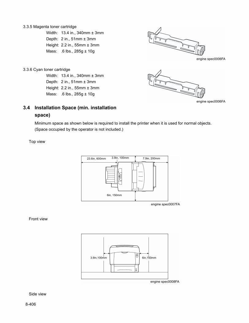
3.3.5 Magenta toner cartridgeWidth: 13.4 in., 340mm ± 3mmDepth: 2 in., 51mm ± 3mmHeight: 2.2 in., 55mm ± 3mmMass: .6 lbs., 285g ± 10g
3.3.6 Cyan toner cartridgeWidth: 13.4 in., 340mm ± 3mmDepth: 2 in., 51mm ± 3mmHeight: 2.2 in., 55mm ± 3mmMass: .6 lbs., 285g ± 10g
3.4 Installation Space (min. installation space)Minimum space as shown below is required to install the printer when it is used for normal objects.(Space occupied by the operator is not included.)
Top view
Front view
Side view
23.6in, 600mm 3.9in, 100mm 7.9in, 200mm
6in, 150mm
3.9in,100mm 6in,150mm
8-406
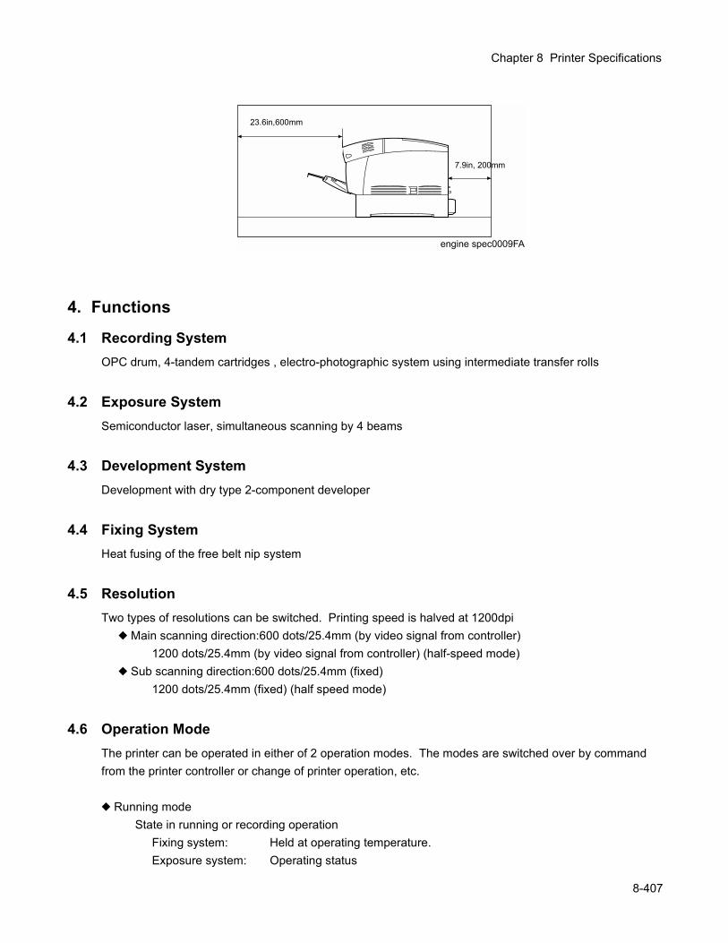
Chapter 8 Printer Specifications
4. Functions
4.1 Recording SystemOPC drum, 4-tandem cartridges , electro-photographic system using intermediate transfer rolls
4.2 Exposure SystemSemiconductor laser, simultaneous scanning by 4 beams
4.3 Development SystemDevelopment with dry type 2-component developer
4.4 Fixing SystemHeat fusing of the free belt nip system
4.5 ResolutionTwo types of resolutions can be switched. Printing speed is halved at 1200dpi
Main scanning direction:600 dots/25.4mm (by video signal from controller)1200 dots/25.4mm (by video signal from controller) (half-speed mode)
Sub scanning direction:600 dots/25.4mm (fixed)1200 dots/25.4mm (fixed) (half speed mode)
4.6 Operation ModeThe printer can be operated in either of 2 operation modes. The modes are switched over by command from the printer controller or change of printer operation, etc.
Running modeState in running or recording operation
Fixing system: Held at operating temperature.Exposure system: Operating status
23.6in,600mm
7.9in, 200mm
8-407
Recording system: Operating statusFuser fan: Operating at high speedRear fan: Operating at high speed
Ready modeReady state
Fixing system: Stop status *1Exposure system: Stop status *2Recording system: Stop statusFuser fan: Stop status *3 (half-speed running)Rear fan: Stop status *3 (half-speed running)
*1: Can be changed ready temperature status from the controller.*2: Can be changed operation status from the controller.*3: Fan status is changed depending on the state (temperature, etc.) of the fixing system.
4.7 Speed ModeSpeed mode of the printer san be switched over between full-speed mode (printing at the highest processing speed of the printer) and half-speed mode (printing at the half-speed processing mode). The controller cannot instruct to change the speed mode.
4.8 Print ModeStandard mode, fine mode and high gross mode are available for the printer. Mode is switched by the instruction from the controller. The high gross mode can be selected only for the plain paper, 600psi.
4.9 Paper Mode11 paper modes are available for this printer. Modes are switched over under the instruction from the controller.
Classification of paper mode(1) Plain paper L mode(2) Plain paper H mode(3) Woodfree paper L mode(4) Woodfree paper H mode(5) Thick paper L mode(6) Thick paper H mode(7) Label L mode(8) Label H mode(9) OHP mode(10) Envelope mode(11) Postcard mode
Relation between the resolution, speed mode, print mode and paper mode is shown in the table below.
8-408
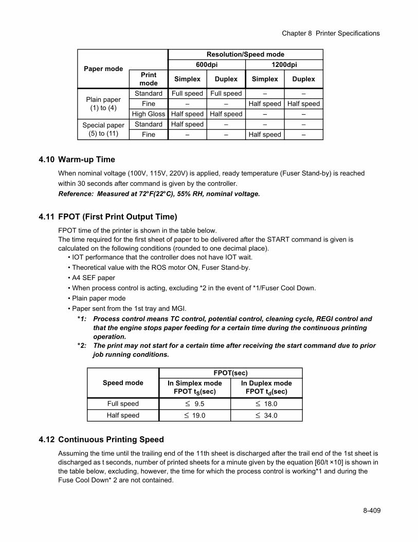
Chapter 8 Printer Specifications
4.10 Warm-up TimeWhen nominal voltage (100V, 115V, 220V) is applied, ready temperature (Fuser Stand-by) is reached within 30 seconds after command is given by the controller.Reference: Measured at 72°F(22°C), 55% RH, nominal voltage.
4.11 FPOT (First Print Output Time)FPOT time of the printer is shown in the table below.The time required for the first sheet of paper to be delivered after the START command is given is calculated on the following conditions (rounded to one decimal place).
• IOT performance that the controller does not have IOT wait.• Theoretical value with the ROS motor ON, Fuser Stand-by.• A4 SEF paper• When process control is acting, excluding *2 in the event of *1/Fuser Cool Down.• Plain paper mode• Paper sent from the 1st tray and MGI.
*1: Process control means TC control, potential control, cleaning cycle, REGI control and that the engine stops paper feeding for a certain time during the continuous printing operation.
*2: The print may not start for a certain time after receiving the start command due to prior job running conditions.
4.12 Continuous Printing SpeedAssuming the time until the trailing end of the 11th sheet is discharged after the trail end of the 1st sheet is discharged as t seconds, number of printed sheets for a minute given by the equation [60/t ×10] is shown in the table below, excluding, however, the time for which the process control is working*1 and during the Fuse Cool Down* 2 are not contained.
Paper mode
Resolution/Speed mode600dpi 1200dpi
Print mode Simplex Duplex Simplex Duplex
Plain paper(1) to (4)
Standard Full speed Full speed – –Fine – – Half speed Half speed
High Gloss Half speed Half speed – –Special paper
(5) to (11)Standard Half speed – – –
Fine – – Half speed –
Speed modeFPOT(sec)
In Simplex modeFPOT tS(sec)
In Duplex modeFPOT td(sec)
Full speed ≤ 9.5 ≤ 18.0Half speed ≤ 19.0 ≤ 34.0
8-409
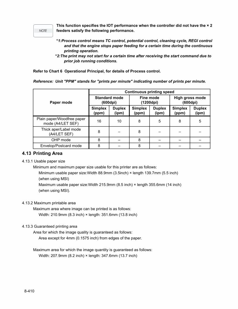
This function specifies the IOT performance when the controller did not have the × 2 feeders satisfy the following performance.
*1:Process control means TC control, potential control, cleaning cycle, REGI control and that the engine stops paper feeding for a certain time during the continuous printing operation.
*2:The print may not start for a certain time after receiving the start command due to prior job running conditions.
Refer to Chart 6 Operational Principal, for details of Process control.
Reference: Unit "PPM" stands for "prints per minute" indicating number of prints per minute.
4.13 Printing Area4.13.1 Usable paper size
Minimum and maximum paper size usable for this printer are as follows:Minimum usable paper size:Width 88.9mm (3.5inch) × length 139.7mm (5.5 inch)(when using MSI)Maximum usable paper size:Width 215.9mm (8.5 inch) × length 355.6mm (14 inch)(when using MSI).
4.13.2 Maximum printable areaMaximum area where image can be printed is as follows:
Width: 210.9mm (8.3 inch) × length: 351.6mm (13.8 inch)
4.13.3 Guaranteed printing areaArea for which the image quality is guaranteed as follows:
Area except for 4mm (0.1575 inch) from edges of the paper.
Maximum area for which the image quantity is guaranteed as follows:Width: 207.9mm (8.2 inch) × length: 347.6mm (13.7 inch)
Paper mode
Continuous printing speedStandard mode
(600dpi)Fine mode(1200dpi)
High gross mode(600dpi)
Simplex(ppm)
Duplex(ipm)
Simplex(ppm)
Duplex(ipm)
Simplex(ppm)
Duplex(ipm)
Plain paper/Woodfree paper mode (A4/LET SEF) 16 10 8 5 8 5
Thick aper/Label mode(A4/LET SEF) 8 – 8 – – –
OHP mode 8 – 8 – – –Envelop/Postcard mode 8 – 8 – – –
8-410
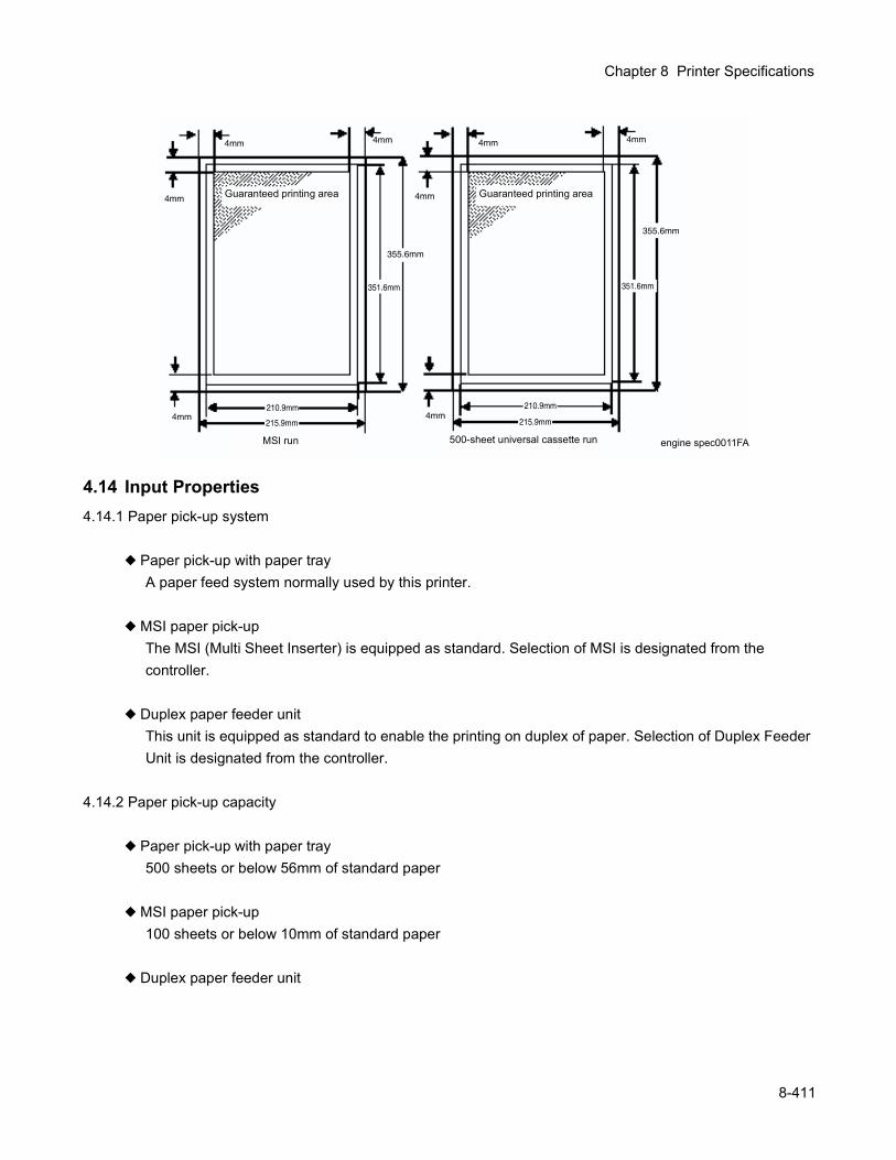
Chapter 8 Printer Specifications
4.14 Input Properties4.14.1 Paper pick-up system
Paper pick-up with paper trayA paper feed system normally used by this printer.
MSI paper pick-upThe MSI (Multi Sheet Inserter) is equipped as standard. Selection of MSI is designated from the controller.
Duplex paper feeder unitThis unit is equipped as standard to enable the printing on duplex of paper. Selection of Duplex Feeder Unit is designated from the controller.
4.14.2 Paper pick-up capacity
Paper pick-up with paper tray500 sheets or below 56mm of standard paper
MSI paper pick-up100 sheets or below 10mm of standard paper
Duplex paper feeder unit
Guaranteed printing area Guaranteed printing area
500-sheet universal cassette runMSI run
8-411
4.15 Output Properties4.15.1 Paper delivery system
Paper can be delivered by the following method. FACE DOWN delivery
4.15.2 Paper delivery capacity FACE DOWN delivery
250 sheets (Letter/A4 standard paper)
4.15.3 Delivery paper size/mass FACE DOWN delivery
All paper sizes applicable to this printer
4.16 Paper4.16.1 Paper type
Paper which can be used with this printer is classified into standard paper, general paper and special paper.
Standard paperUsing this type of paper is recommended. Reliability, operability and print image quality are the application range of the specifications.Following paper is the standard paper.
* Xerox 4200 DP 20lb* Xerox premier 80gsm
General paperGeneral paper is plain paper except standard paper and special paper, and its reliability and running performance are within the specification, but the print image quality is out of the specification.
Special paperSpecial paper except for plain paper. Reliability and operability are the applicable range of specifica-tions but the print image quality is out of the applicable range of specifications.
4.16.2 Paper mass Paper feed from paper tray
"60 to 105 gsm" or "16 - 28 lb" Paper feed from MSI
"60 to 216 gsm" or "16 - 80 lb"
4.16.3 Paper sizePaper size which can be set to each paper pick-up unit is shown in the table below.
8-412
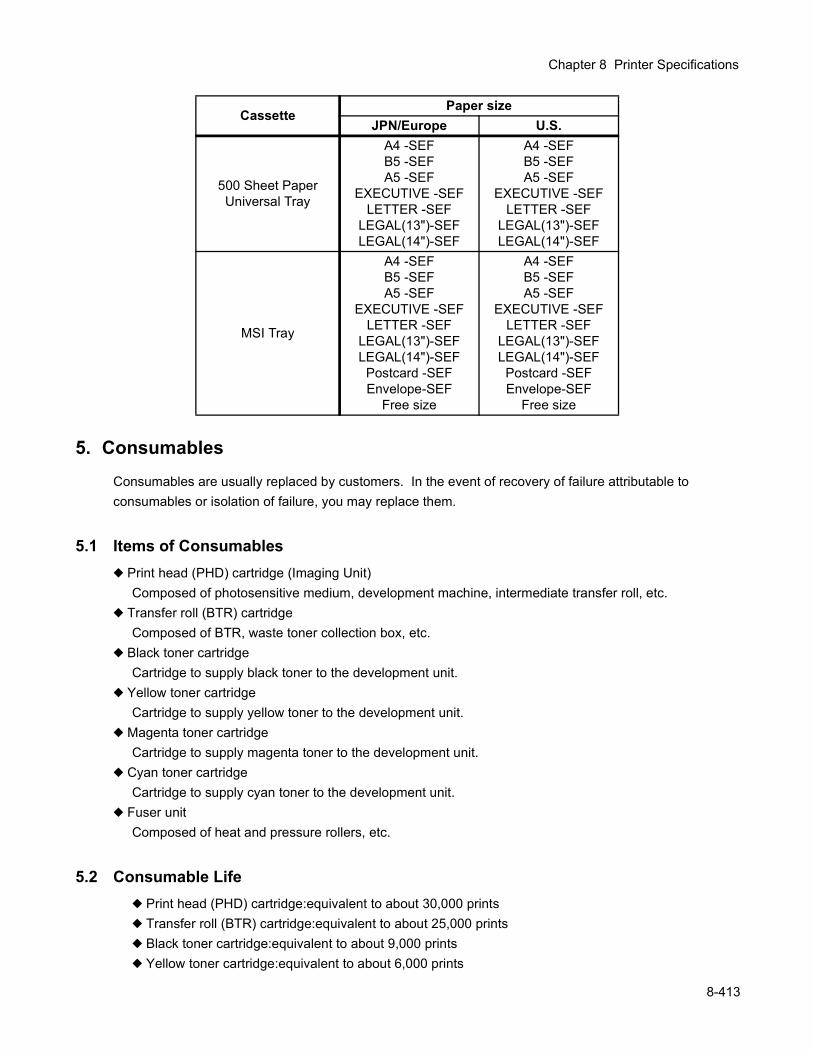
Chapter 8 Printer Specifications
5. ConsumablesConsumables are usually replaced by customers. In the event of recovery of failure attributable to consumables or isolation of failure, you may replace them.
5.1 Items of Consumables Print head (PHD) cartridge (Imaging Unit)
Composed of photosensitive medium, development machine, intermediate transfer roll, etc. Transfer roll (BTR) cartridge
Composed of BTR, waste toner collection box, etc. Black toner cartridge
Cartridge to supply black toner to the development unit. Yellow toner cartridge
Cartridge to supply yellow toner to the development unit. Magenta toner cartridge
Cartridge to supply magenta toner to the development unit. Cyan toner cartridge
Cartridge to supply cyan toner to the development unit. Fuser unit
Composed of heat and pressure rollers, etc.
5.2 Consumable Life Print head (PHD) cartridge:equivalent to about 30,000 prints Transfer roll (BTR) cartridge:equivalent to about 25,000 prints Black toner cartridge:equivalent to about 9,000 prints Yellow toner cartridge:equivalent to about 6,000 prints
CassettePaper size
JPN/Europe U.S.
500 Sheet PaperUniversal Tray
A4 -SEFB5 -SEFA5 -SEF
EXECUTIVE -SEFLETTER -SEF
LEGAL(13")-SEFLEGAL(14")-SEF
A4 -SEFB5 -SEFA5 -SEF
EXECUTIVE -SEFLETTER -SEF
LEGAL(13")-SEFLEGAL(14")-SEF
MSI Tray
A4 -SEFB5 -SEFA5 -SEF
EXECUTIVE -SEFLETTER -SEF
LEGAL(13")-SEFLEGAL(14")-SEF
Postcard -SEFEnvelope-SEF
Free size
A4 -SEFB5 -SEFA5 -SEF
EXECUTIVE -SEFLETTER -SEF
LEGAL(13")-SEFLEGAL(14")-SEF
Postcard -SEFEnvelope-SEF
Free size
8-413

Magenta toner cartridge:equivalent to about 6,000 prints Cyan toner cartridge:equivalent to about 6,000 prints Fuser unit:equivalent to about 100,000 prints
5.3 Parts Requiring Periodical ReplacementFollowing parts are replaced when a certain number of sheets are printed (life over) to prevent troubles.
FUSE ASSY:Equivalent to about 100.000 prints RETARD ROLL:Equivalent to about 100,000 prints
6. Operating Environment
6.1 Installation Temperature / HumidityOperated at: 5 to 32°C(41 to 90°F) / 15 to 85% RH
6.2 Installation Altitude0 to 3,100m(10,170ft)
6.3 Installation HorizontalityBefore and after the installation surface:within 5mm in 646mmRight and left of installation surface:within 10mm in 560mm
6.4 Ambient Lighting3000 Lux or less (without no direct sun beams)
7. Safety / Environment Conditions
7.1 Safety Standard 100V / 120V system
UL1950 3rd EditionCSA C22.2 No.950-M95
220V / 240V systemIEC60950 2nd Edition
7.2 Laser Safety Standard 100V / 120V system
FDA21CFR Chapter 1, Subchapter J, Section 1010, 1040 220V / 240V system
IEC60825 Class 1 Laser Product
7.3 EMI 100V system
8-414
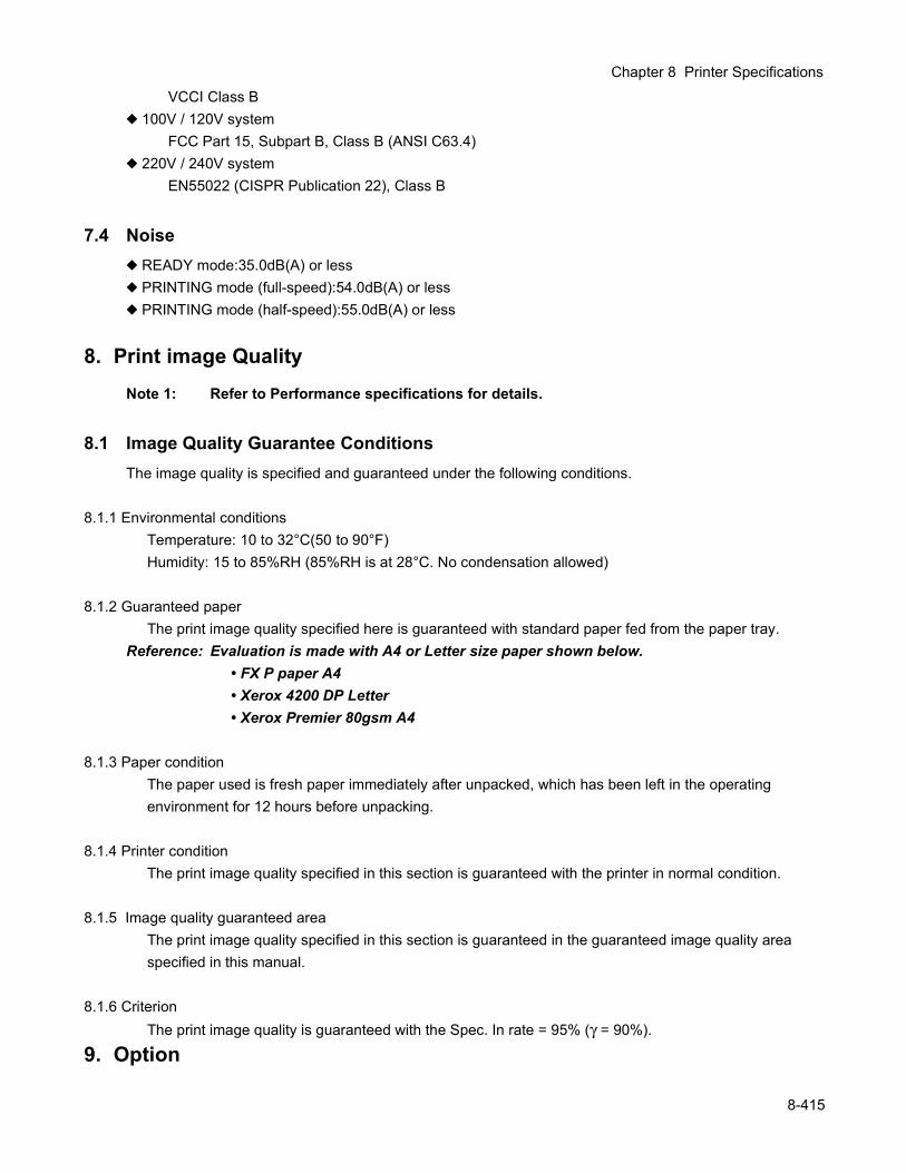
Chapter 8 Printer Specifications
VCCI Class B100V / 120V systemFCC Part 15, Subpart B, Class B (ANSI C63.4)
220V / 240V systemEN55022 (CISPR Publication 22), Class B
7.4 Noise READY mode:35.0dB(A) or less PRINTING mode (full-speed):54.0dB(A) or less PRINTING mode (half-speed):55.0dB(A) or less
8. Print image QualityNote 1: Refer to Performance specifications for details.
8.1 Image Quality Guarantee ConditionsThe image quality is specified and guaranteed under the following conditions.
8.1.1 Environmental conditionsTemperature: 10 to 32°C(50 to 90°F)Humidity: 15 to 85%RH (85%RH is at 28°C. No condensation allowed)
8.1.2 Guaranteed paperThe print image quality specified here is guaranteed with standard paper fed from the paper tray.
Reference: Evaluation is made with A4 or Letter size paper shown below.• FX P paper A4• Xerox 4200 DP Letter• Xerox Premier 80gsm A4
8.1.3 Paper conditionThe paper used is fresh paper immediately after unpacked, which has been left in the operating environment for 12 hours before unpacking.
8.1.4 Printer conditionThe print image quality specified in this section is guaranteed with the printer in normal condition.
8.1.5 Image quality guaranteed areaThe print image quality specified in this section is guaranteed in the guaranteed image quality area specified in this manual.
8.1.6 CriterionThe print image quality is guaranteed with the Spec. In rate = 95% (γ = 90%).
9. Option
8-415

9.1 Options to be Installed by Users Users can install the following 2 types of units.Åü OPTION FEEDER
Two layers of UNIVERSAL TRAY can be added under the printer. This is a paper -pickup unit to pick up paper from each tray.
Åü Earthquake kit (EARTHQUAKE KIT)Kit of fixing parts fix the printer as anti-earthquake provision.
8-416

Index

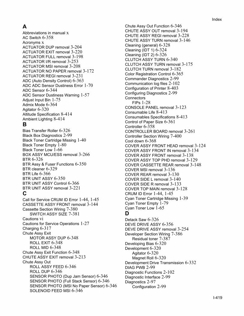
Index
AAbbreviations in manual xAC Switch 6-358Acronyms xACTUATOR DUP removal 3-204ACTUATOR EXIT removal 3-220ACTUATOR FULL removal 3-198ACTUATOR I/R removal 3-253ACTUATOR MSI removal 3-208ACTUATOR NO PAPER removal 3-172ACTUATOR REGI removal 3-231ADC (Auto Density Control) 6-363ADC ADC Sensor Dustiness Error 1-70ADC Sensor 6-344ADC Sensor Dustiness Warning 1-57Adjust Input Bin 1-75Admix Mode 6-364Agitator 6-320Altitude Specification 8-414Ambient Lighting 8-414BBias Transfer Roller 6-326Black Box Diagnostics 2-99Black Toner Cartridge Missing 1-40Black Toner Empty 1-80Black Toner Low 1-66BOX ASSY MCU/ESS removal 3-266BTR 6-326BTR Assy & Fuser Functions 6-350BTR cleaner 6-329BTR Life 6-366BTR UNIT ASSY 6-350BTR UNIT ASSY Control 6-366BTR UNIT ASSY removal 3-221CCall for Service CRUM ID Error 1-44, 1-45CASSETTE ASSY FRONT removal 3-144Cassette Section Wiring 7-380
SWITCH ASSY SIZE 7-381Cautions viCautions for Service Operations 1-27Charging 6-317Chute Assy Exit
MOTOR ASSY DUP 6-348ROLL EXIT 6-348ROLL MID 6-348
Chute Assy Exit Function 6-348CHUTE ASSY EXIT removal 3-213Chute Assy Out
ROLL ASSY FEED 6-346ROLL DUP 6-346SENSOR PHOTO (Dup Jam Sensor) 6-346SENSOR PHOTO (Full Stack Sensor) 6-346SENSOR PHOTO (MSI No Paper Sensor) 6-346SOLENOID FEED MSI 6-346
Chute Assy Out Function 6-346CHUTE ASSY OUT removal 3-194CHUTE ASSY REGI removal 3-228CHUTE ASSY TURN removal 3-146Cleaning (general) 6-328Cleaning (IDT 1) 6-324Cleaning (IDT 2) 6-326CLUTCH ASSY TURN 6-340CLUTCH ASSY TURN removal 3-175CLUTCH TURN removal 3-182Color Registration Control 6-365Commander Diagnostics 2-99Communication log files 2-102Configuration of Printer 8-403Configuring Diagnostics 2-99Connectors
FIPs 1-28CONSOLE PANEL removal 3-123Consumable Life 8-413Consumables Specifications 8-413Control of Paper Size 6-361Controller 6-358CONTROLLER BOARD removal 3-261Controller Section Wiring 7-400Cool down 6-368COVER ASSY FRONT HEAD removal 3-124COVER ASSY FRONT IN removal 3-134COVER ASSY FRONT removal 3-138COVER ASSY TOP PHD removal 3-129COVER CASSETTE REAR removal 3-148COVER MSI removal 3-136COVER REAR removal 3-130COVER SIDE L removal 3-140COVER SIDE R removal 3-133COVER TOP MAIN removal 3-128CRUM ID Error 1-44, 1-45Cyan Toner Cartridge Missing 1-39Cyan Toner Empty 1-79Cyan Toner Low 1-65DDetack Saw 6-326DEVE DRIVE ASSY 6-356DEVE DRIVE ASSY removal 3-254Developer Section Wiring 7-386
Residual toner 7-387Developing Bias 6-320Development 6-320
Agitator 6-320Magnet Roll 6-320
Development Drive Transmission 6-332DIAG PWB 2-99Diagnostic Functions 2-102Diagnostic Interface 2-99Diagnostics 2-97
Configuration 2-99
I-419
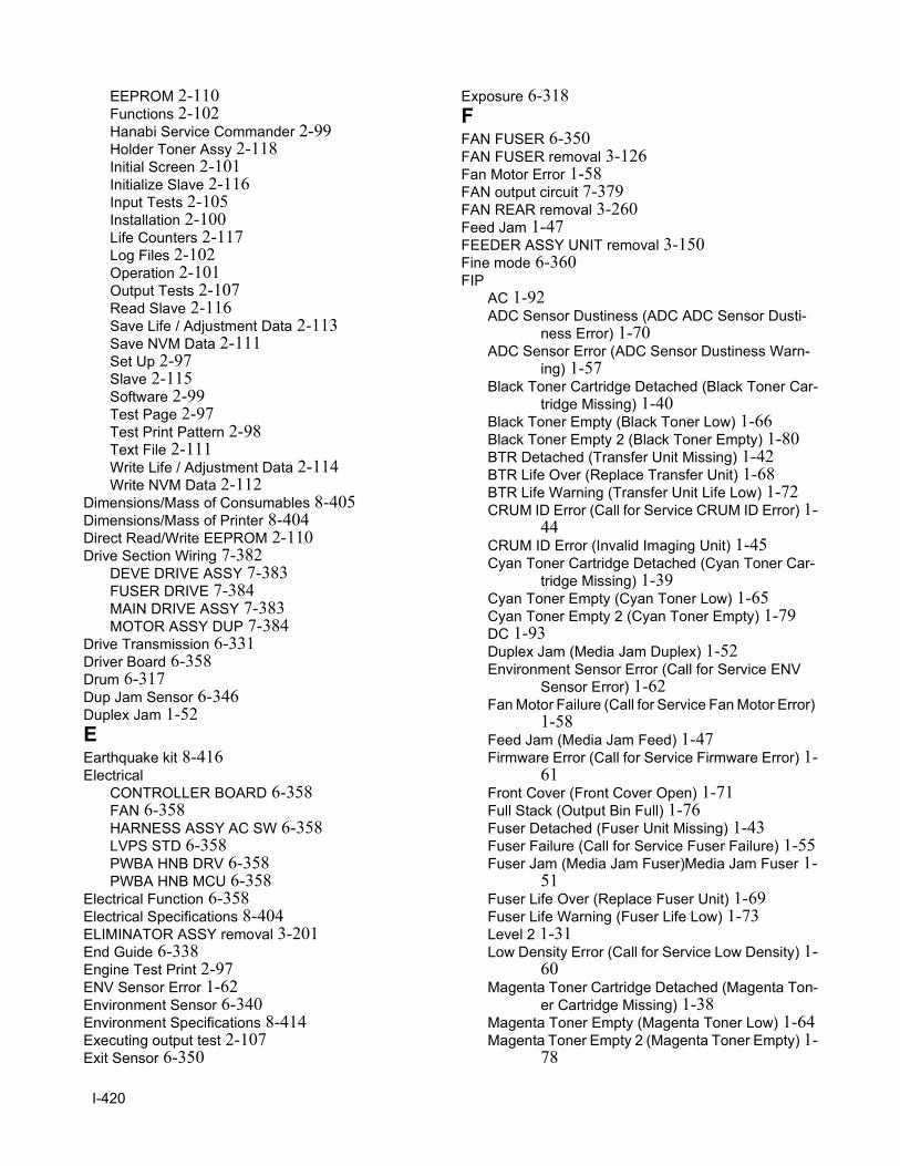
EEPROM 2-110Functions 2-102Hanabi Service Commander 2-99Holder Toner Assy 2-118Initial Screen 2-101Initialize Slave 2-116Input Tests 2-105Installation 2-100Life Counters 2-117Log Files 2-102Operation 2-101Output Tests 2-107Read Slave 2-116Save Life / Adjustment Data 2-113Save NVM Data 2-111Set Up 2-97Slave 2-115Software 2-99Test Page 2-97Test Print Pattern 2-98Text File 2-111Write Life / Adjustment Data 2-114Write NVM Data 2-112
Dimensions/Mass of Consumables 8-405Dimensions/Mass of Printer 8-404Direct Read/Write EEPROM 2-110Drive Section Wiring 7-382
DEVE DRIVE ASSY 7-383FUSER DRIVE 7-384MAIN DRIVE ASSY 7-383MOTOR ASSY DUP 7-384
Drive Transmission 6-331Driver Board 6-358Drum 6-317Dup Jam Sensor 6-346Duplex Jam 1-52EEarthquake kit 8-416Electrical
CONTROLLER BOARD 6-358FAN 6-358HARNESS ASSY AC SW 6-358LVPS STD 6-358PWBA HNB DRV 6-358PWBA HNB MCU 6-358
Electrical Function 6-358Electrical Specifications 8-404ELIMINATOR ASSY removal 3-201End Guide 6-338Engine Test Print 2-97ENV Sensor Error 1-62Environment Sensor 6-340Environment Specifications 8-414Executing output test 2-107Exit Sensor 6-350
Exposure 6-318FFAN FUSER 6-350FAN FUSER removal 3-126Fan Motor Error 1-58FAN output circuit 7-379FAN REAR removal 3-260Feed Jam 1-47FEEDER ASSY UNIT removal 3-150Fine mode 6-360FIP
AC 1-92ADC Sensor Dustiness (ADC ADC Sensor Dusti-
ness Error) 1-70ADC Sensor Error (ADC Sensor Dustiness Warn-
ing) 1-57Black Toner Cartridge Detached (Black Toner Car-
tridge Missing) 1-40Black Toner Empty (Black Toner Low) 1-66Black Toner Empty 2 (Black Toner Empty) 1-80BTR Detached (Transfer Unit Missing) 1-42BTR Life Over (Replace Transfer Unit) 1-68BTR Life Warning (Transfer Unit Life Low) 1-72CRUM ID Error (Call for Service CRUM ID Error) 1-
44CRUM ID Error (Invalid Imaging Unit) 1-45Cyan Toner Cartridge Detached (Cyan Toner Car-
tridge Missing) 1-39Cyan Toner Empty (Cyan Toner Low) 1-65Cyan Toner Empty 2 (Cyan Toner Empty) 1-79DC 1-93Duplex Jam (Media Jam Duplex) 1-52Environment Sensor Error (Call for Service ENV
Sensor Error) 1-62Fan Motor Failure (Call for Service Fan Motor Error)
1-58Feed Jam (Media Jam Feed) 1-47Firmware Error (Call for Service Firmware Error) 1-
61Front Cover (Front Cover Open) 1-71Full Stack (Output Bin Full) 1-76Fuser Detached (Fuser Unit Missing) 1-43Fuser Failure (Call for Service Fuser Failure) 1-55Fuser Jam (Media Jam Fuser)Media Jam Fuser 1-
51Fuser Life Over (Replace Fuser Unit) 1-69Fuser Life Warning (Fuser Life Low) 1-73Level 2 1-31Low Density Error (Call for Service Low Density) 1-
60Magenta Toner Cartridge Detached (Magenta Ton-
er Cartridge Missing) 1-38Magenta Toner Empty (Magenta Toner Low) 1-64Magenta Toner Empty 2 (Magenta Toner Empty) 1-
78
I-420
Index
Media Type Mismatch (Media Type Mismatch) 1-46NV-RAM Error (Call for Service NVRAM Error) 1-
56P1 Light (Undertoned) Prints 1-82P10 Unfused Image or Image Easily Rubs off of
Page 1-91P2 Blank Prints 1-83P3 Black Prints 1-84P4 Vertical Band Deletions 1-85P5 Horizontal Band Deletions 1-86P6 Black (color) spots 1-87P7 Background 1-88P8 Skewed Image 1-89P9 Crease 1-90PHD Detached (Imaging Unit Missing) 1-41PHD Life Over (Replace Imaging Unit) 1-67Regi Jam (Media Jam Registration) 1-50ROS Failure (Call for Service ROS Motor) 1-54Upper Cassette Detached (Adjust Input Bin) 1-75Yellow Toner Cartridge Detached (Yellow Toner
Cartridge Missing) 1-37Yellow Toner Empty (Yellow Toner Low) 1-63Yellow Toner Empty 2 (Yellow Toner Empty) 1-77
FIPsCautions for FIP UseTroubleshooting
FIPs 1-28Firmware Error 1-61Fixing 6-327Flow of Print Data 6-330Frame & Drive Function 6-356Front Assy In
FUSER DRIVE ASSY 6-344SENSOR ADC ASSY 6-344SENSOR TNR FULL 6-344
Front Assy In Function 6-344FRONT ASSY IN removal 3-184Front Cover Open 1-71Full Stack Sensor 6-346Functions Specifications 8-407FUSER ASSY 6-350FUSER ASSY removal 3-217FUSER DRIVE ASSY removal 3-190Fuser Failure 1-55Fuser Jam 1-51Fuser Life Low 1-73Fuser section 7-374Fuser Section Wiring 7-390Fuser temperature control 6-368Fuser Unit Missing 1-43Fusing 6-327GGear Layout 6-334General Cleaning 6-328General Wiring Diagram 7-371
GUIDE INDICATOR removal 3-164HHARNESS ASSY AC SW removal 3-264HARNESS ASSY OPFREC removal 3-157High Area Coverage Mode 6-364High Gloss mode 6-360HOLDER RETARD removal 3-142HOLDER TCRU ASSY 6-354HOLDER TCRU ASSY (1) removal 3-239HOLDER TCRU ASSY (2) removal 3-240HOLDER TCRU ASSY (3) removal 3-241HOLDER TCRU ASSY (4) removal 3-242HOLDER TCRU ASSY UNIT removal 3-236Holder Toner Assy 2-118HOUSING ASSY CONTACT removal 3-268HOUSING ASSY FEEDER L removal 3-152HOUSING ASSY FEEDER R removal 3-154Housing Assy Retard
MSI Turn Clutch 6-342ROLL TURN 6-342
Housing Assy Retard Function 6-342HOUSING ASSY RETARD removal 3-178HSG ASSY BIAS removal 3-226Humidity Sensor 6-340HVPS Control 6-358IIDT 1 6-322IDT 2 6-324Image Trouble FIP 1-81Imaging Unit 6-316Imaging Unit Missing 1-41INDICATOR removal 3-162Initialize Slave 2-116Installation Altitude 8-414Installation Horizontality 8-414Installation Space 8-406Installation Temperature/Humidity 8-414Installing Diagnostics 2-100Interlock Switch 6-358LLaser Unit 6-318LATCH L removal 3-193LATCH OUT removal 3-206LATCH R removal 3-192LED Light Quantity Control 6-364Level 1 FIP 1-30Level 2 FIP 1-31LEVER DRUM L removal 3-247LEVER DRUM R removal 3-250LEVER LOW PAPER removal 3-160Life Counters 2-117LINK ACTUATOR removal 3-173LINK L removal 3-131LINK R removal 3-132List of Abbreviations x
I-421
List of Plug/Jacks 4-273Low Density Error 1-60Low Paper Sensor 6-340LOW PAPER sensor removal 3-171LVPS 6-358LVPS overcurrent protection circuit 7-379LVPS overvoltage protection circuit 7-379LVPS removal 3-262MMagenta Toner Cartridge Missing 1-38Magenta Toner Empty 1-78Magenta Toner Low 1-64Magnet Roller 6-320MAIN DRIVE ASSY 6-356MAIN DRIVE ASSY removal 3-255Main Drive Transmission 6-331Major Component Functions 6-337
BTR Assy & Fuser 6-350Chute Assy Exit 6-348Chute Assy Out 6-346Electrical 6-358Frame & Drive 6-356Front Assy In 6-344Housing Assy Retard 6-342Paper Cassette 6-338Paper Feeder 6-340TCRU Assy 6-354Xerographics 6-352
MCU 6-358MCU removal 3-258Mechanical Board 6-358Mechanical Drive 6-331Mechanical Specifications 8-404Media Jam Duplex 1-52Media Jam Feed 1-47Media Jam Registration 1-50Media Type Mismatch 1-46MOTOR ASSY DUP 6-348MOTOR ASSY DUP removal 3-216MSI No Paper Sensor 6-346MSI Turn Clutch 6-342NNo Paper Sensor 6-340NO PAPER sensor removal 3-170Noise Specification 8-415NVRAM Error 1-56OOHP SENSOR ASSY 6-352OHP SENSOR ASSY removal 3-232OPC 6-317Operation of Diagnostics 2-95, 2-101Operation of EEPROM 2-110Option Specifications 8-415Output Bin Full 1-76Output stop by Interlock Switch 7-379
Output Test Types 2-108Output Tests 2-107PPaper Cassette Function 6-338Paper Feed Section Wiring 7-398Paper Feeder
CLUTCH ASSY TURN 6-340ROLL ASSY FEED 6-340ROLL ASSY TURN 6-340SENSOR HUM TEMP 6-340SENSOR PHOTO (Low Paper Sensor) 6-340SENSOR PHOTO (No Paper Sensor) 6-340SOLENOID FEED 6-340SWITCH ASSY SIZE 6-340
Paper Feeder Function 6-340Paper Size Control 6-361, 7-381Paper Transport 6-335Parts List 5-279
BTR Assy & Fuser 5-300Chute Assy Exit 5-298Chute Assy In 5-294Chute Assy Out 5-296Electrical 5-308Frame & Drive 5-306Harness 5-310Housing Assy Retard 5-292Paper Cassette 5-284Paper Feeder I 5-286Paper Feeder II 5-288Paper Feeder III 5-290TCRU Assy 5-304Xerographics 5-302
Patches 6-362PCDC (Pixel Count Dispense Control) 6-363Periodic Replacement 8-414PHD Assembly 6-316PHD ASSY 6-352Photoconductor 6-317PICKUP ASSY removal 3-166PLATE ASSY BOTTOM MSI removal 3-212Plug/Jack (P/J) Connector Locations 4-271Plug/Jack layout diagram 4-275Potential Control 6-362Power Consumption 8-404Power Source 8-404Primary transfer 6-322
IDT 1 6-322Principles of Operation 6-313Print Head Assembly 6-352Print image Quality Specifications 8-415Printer Specifications 8-401Printing Process 6-315
Charging with electricity 6-317Cleaning (general) 6-328Cleaning (IDT 1) 6-324
I-422
Index
Cleaning (IDT 2) 6-326Development 6-320Exposure 6-318Fixing 6-327Primary transfer 6-322Schematic Diagram 6-316Secondary transfer 6-324Static elimination 6-326Summary 6-315Tertiary transfer 6-326Process Control 6-362PWBA ASSY EARTH removal 3-256PWBA EEPROM STD 6-354PWBA EEPROM STD removal 3-245PWBA HNB DRV 6-358PWBA HNB DRV removal 3-265PWBA HNB MCU removal 3-258RRead Slave 2-116Refresher 6-317Registration Clutch 6-352Registration Jam 1-50Registration Sensor 6-352Removal and Replacement Procedures 3-119
BTR ASSY & FUSER 3-217CHUTE ASSY EXIT 3-213CHUTE ASSY OUT 3-194COVERS 3-123Description of procedures 3-122ELECTRICAL 3-258FRAME & DRIVE 3-247FRONT ASSY IN 3-184HOUSING ASSY RETARD 3-178PAPER CASSETTE 3-141PAPER FEEDER 3-146TCRU ASSY 3-236XEROGRAPHICS 3-224
Replace Fuser Unit 1-69Replace Imaging Unit 1-67Replace Transfer Unit 1-68ROLL ASSY (Cassette) 6-338ROLL ASSY EXIT removal 3-218ROLL ASSY FEED 6-340, 6-346ROLL ASSY FEED removal 3-168, 3-207ROLL ASSY removal 3-141, 3-177ROLL ASSY RETARD removal 3-180ROLL ASSY TURN 6-340ROLL ASSY TURN removal 3-176ROLL DUP 6-346ROLL DUP removal 3-202ROLL EXIT 6-348ROLL EXIT removal 3-214ROLL MID 6-348ROLL MID removal 3-215ROLL TURN 6-342
ROLL TURN removal 3-179Roller Circumferences 1-81ROS Assembly 6-318ROS ASSY 6-352ROS ASSY removal 3-224ROS Control 6-358ROS Light Quantity Control 6-361ROS Motor Error 1-54ROS Section Wiring 7-392RTC (Rubber Tube Charge) 6-317SSafety viSafety / Environment Specifications 8-414Save Life / Adjustment Data 2-113Save NVM Data 2-111Secondary transfer 6-324
IDT 2 6-324SENSOR ADC ASSY 6-364SENSOR ADC ASSY removal 3-187SENSOR HUM TEMP removal 3-156SENSOR PHOTO duplex removal 3-199SENSOR PHOTO FULL STACK removal 3-197SENSOR PHOTO MSI removal 3-200SENSOR PHOTO REGI removal 3-230SENSOR TNR FULL removal 3-188SENSOR TONER LOW 6-354SENSOR TONER LOW removal 3-244SHAFT ASSY ROLL FEED removal 3-210Shorting Pins for Test Print 2-97S-HVPS 6-354S-HVPS removal 3-246Side Guide 6-338Slave 2-115SOLENOID FEED 6-340SOLENOID FEED MSI 6-346SOLENOID FEED MSI removal 3-209SOLENOID FEED removal 3-174Specifications
Consumable Life 8-413Consumables 8-413Continuous Printing Speed 8-409Development System 8-407Electrical 8-404Environment 8-414Exposure System 8-407First Print Output Time 8-409Fixing System 8-407Functions 8-407Input Properties 8-411Mechanical 8-404Noise 8-415Operation Mode 8-407Option 8-415Output Properties 8-412Paper delivery capacity 8-412
I-423
Paper Mode 8-408Paper pick-up capacity 8-411Paper size 8-412Periodic Replacement 8-414Print image Quality 8-415Print Mode 8-408Printing Area 8-410Recording System 8-407Resolution 8-407Safety / Environment 8-414Speed Mode 8-408Warm-up Time 8-409
Standard mode 6-360Static elimination 6-326STRAP removal 3-222STUD RTD removal 3-183SWITCH ASSY SIZE 6-340SWITCH ASSY SIZE removal 3-158SWITCH TCRU ASSY removal 3-243TTandem System 6-315, 6-365TCRU
HOLDER TCRU ASSY 6-354PWBA EEPROM STD 6-354SENSOR TONER LOW (Y,M,C,K) 6-354S-HVPS 6-354SWITCH TCRU ASSY (Y,M.C.K) 6-354
TCRU Assy Function 6-354TCRU Drive Transmission 6-332Temperature Sensor 6-340Temperature/Humidity Specification 8-414Tertiary Transfer
BTR 6-326Tertiary transfer 6-326Test Print 2-97, 2-103Test Print Pattern 2-98Theory of Operation 6-313Toner Bottle Present Switch 6-354Toner Control 6-367Toner Density Control 6-363Toner Empty Error 6-367Toner Empty Warning 6-367TONER LOW 6-367Transfer Unit Life Low 1-72Transfer Unit Missing 1-42TRAY ASSY MSI removal 3-137Troubleshooting 1-23, 1-81
Clearing the Error 1-34Error / Status Codes 1-31Level 1 FIP 1-30Level 2 FIP 1-31Preparation 1-26
Types of input test 2-105Types of output tests 2-108
UUnpacking the Printer xiWWarm-up Time 8-409Waste Toner Collection 6-329Wiring Diagram
Controller section 7-374Developer section 1 7-373Developer section 2 7-373Drive section 7-373Paper feed section 7-374Power supply 7-373ROS section 7-374Xerographics section 2 7-374Xerographics section1 7-374
Wiring Diagrams and Signal Information 7-369Write Life / Adjustment Data 2-114Write NVM Data 2-112XXerographics
CHUTE REGI (Regi Clutch) 6-352OHP SENSOR ASSY 6-352PHD ASSY 6-352ROS ASSY 6-352SENSOR PHOTO (Regi Sensor) 6-352
Xerographics Function 6-352Xerographics Wiring 7-394, 7-396YYellow Toner Cartridge Missing 1-37Yellow Toner Empty 1-77Yellow Toner Low 1-63
I-424