Embed Size (px)
Citation preview
Magdrive Linear Actuator
Read this manual before installing, operating
or maintaining this actuator. Failure to follow
safety precautions and instructions could
cause actuator failure and result in serious
injury, death or property damage.
Installation, operation and maintenance manual
ООО "Индастриал Партнер"
Авторизованный дистрибьютор SKF
www.skf.indpart.ru [email protected]
8(495)223-07-69
Техническая поддержка:
[email protected], 8(495)223-07-69
L5
31
1,2
59
0E
.1/3
.07
- 15 M
arch 2
007 ® SKF and Magnetic are registered trademarks of the SKF Group.
© SKF 2005 The contents of this publication are the copyright of the publisher and may not be reproduced (even extracts) unless prior written permission is granted. Every care has been taken to ensure the accuracy of the information contained in this publication but no lia-bility can be accepted for any loss or damage whether direct, indirect or consequential arising out of the use of the information contained herein.
ООО "Индастриал Партнер"
Авторизованный дистрибьютор SKF
www.skf.indpart.ru [email protected]
8(495)223-07-69
Техническая поддержка:
[email protected], 8(495)223-07-69
3
L5
31
1,2
59
0E
.1/3.0
7
iTable of Contents
Basic Principles . . . . . . . . . . . . . . . . . . . . . . . . . . . . . . . . . . . . . 4
1 Introduction . . . . . . . . . . . . . . . . . . . . . . . . . . . . . . . . . . . . . . . . . . . . . . . 4Operating instructions . . . . . . . . . . . . . . . . . . . . . . . . . . . . . . . . . . . . . . . 4Organizational Measures . . . . . . . . . . . . . . . . . . . . . . . . . . . . . . . . . . . . . 5Conventions . . . . . . . . . . . . . . . . . . . . . . . . . . . . . . . . . . . . . . . . . . . . . . . 6
2 Safety . . . . . . . . . . . . . . . . . . . . . . . . . . . . . . . . . . . . . . . . . . . . . . . . . . . . 8Safety Program . . . . . . . . . . . . . . . . . . . . . . . . . . . . . . . . . . . . . . . . . . . . 8Other hazards . . . . . . . . . . . . . . . . . . . . . . . . . . . . . . . . . . . . . . . . . . . . . 10
3 Structure and Function. . . . . . . . . . . . . . . . . . . . . . . . . . . . . . . . . . . . . . 13Construction . . . . . . . . . . . . . . . . . . . . . . . . . . . . . . . . . . . . . . . . . . . . . . 13Function . . . . . . . . . . . . . . . . . . . . . . . . . . . . . . . . . . . . . . . . . . . . . . . . . 14Options and accessories . . . . . . . . . . . . . . . . . . . . . . . . . . . . . . . . . . . . . 15
Normal Operation . . . . . . . . . . . . . . . . . . . . . . . . . . . . . . . . . . . .16
4 Normal Operation . . . . . . . . . . . . . . . . . . . . . . . . . . . . . . . . . . . . . . . . . . 16Normal Operation . . . . . . . . . . . . . . . . . . . . . . . . . . . . . . . . . . . . . . . . . . 16
Special Operations . . . . . . . . . . . . . . . . . . . . . . . . . . . . . . . . . . .18
5 Installation and Initial Start-Up . . . . . . . . . . . . . . . . . . . . . . . . . . . . . . . 18Preparation. . . . . . . . . . . . . . . . . . . . . . . . . . . . . . . . . . . . . . . . . . . . . . . 18Installation and Connections. . . . . . . . . . . . . . . . . . . . . . . . . . . . . . . . . . 19Initial Start-Up . . . . . . . . . . . . . . . . . . . . . . . . . . . . . . . . . . . . . . . . . . . . 21
6 Maintenance, Clearing malfunctions, Repairs . . . . . . . . . . . . . . . . . . . . . 22Maintenance . . . . . . . . . . . . . . . . . . . . . . . . . . . . . . . . . . . . . . . . . . . . . . 22Malfunctions . . . . . . . . . . . . . . . . . . . . . . . . . . . . . . . . . . . . . . . . . . . . . . 23Repair . . . . . . . . . . . . . . . . . . . . . . . . . . . . . . . . . . . . . . . . . . . . . . . . . . . 26
7 Removing from service, dismantling and disposal . . . . . . . . . . . . . . . . . 27Shutting down . . . . . . . . . . . . . . . . . . . . . . . . . . . . . . . . . . . . . . . . . . . . 27Dismantling. . . . . . . . . . . . . . . . . . . . . . . . . . . . . . . . . . . . . . . . . . . . . . . 27Storage . . . . . . . . . . . . . . . . . . . . . . . . . . . . . . . . . . . . . . . . . . . . . . . . . . 27Disposal . . . . . . . . . . . . . . . . . . . . . . . . . . . . . . . . . . . . . . . . . . . . . . . . . 28
Appendix . . . . . . . . . . . . . . . . . . . . . . . . . . . . . . . . . . . . . . . . . .29
8 Appendix . . . . . . . . . . . . . . . . . . . . . . . . . . . . . . . . . . . . . . . . . . . . . . . . . 29Technical data. . . . . . . . . . . . . . . . . . . . . . . . . . . . . . . . . . . . . . . . . . . . . 29Plans and diagrams . . . . . . . . . . . . . . . . . . . . . . . . . . . . . . . . . . . . . . . . 29Standards applied. . . . . . . . . . . . . . . . . . . . . . . . . . . . . . . . . . . . . . . . . . 30
ООО "Индастриал Партнер"
Авторизованный дистрибьютор SKF
www.skf.indpart.ru [email protected]
8(495)223-07-69
Техническая поддержка:
[email protected], 8(495)223-07-69
4
L5
31
1,2
59
0E
.1/3.0
7
Basic Principles
The following chapters are part of the basic principles:
■ 1. Introduction, page 4■ 2. Safety, page 8■ 3. Structure and Function, page 13
1. Introduction
This chapter contains information on the organization and structure of the oper-ating instructions. It makes the instruction manual easier to handle and enables quick access to the desired information.
Operating instructions
Magnetic Elektromotoren AG manufactures state of the art electric motors.
The purpose of these operating instructions is to introduce you, as the user and the entity doing the further processing, to correct utilization and safe use.
For this goal to be achieved, it is essential that you very carefully read the chapter on safety (2. Safety, page 8) and follow the instructions in this manual.
Validity
The instructions in this manual refer to the linear actuator MAGDRIVE™ with the follow-ing identification:
■ Manufacturer: Magnetic Elektromotoren AG, Liestal■ Product name: Linear actuator MAGDRIVE™■ Type designation: MD■ Year of manufacture: from 2005■ CE Mark: according to technical documentation■ Serial number: from production start
Target audience and obligation to read
These operating instructions are intended for technical personnel and authorized users who use the linear actuator MAGDRIVE™ in their products and work with it. The operat-ing authority determines who is authorized as a user.
We distinguish between different user groups, as the requirements on the users vary, depending on the activity they perform.
Please note: You can find definitions of user groups along with their corresponding requirements in the chapter on safety (2. Safety, page 8). You can assume one or more of these user groups provided you meet the applicable requirements.
ООО "Индастриал Партнер"
Авторизованный дистрибьютор SKF
www.skf.indpart.ru [email protected]
8(495)223-07-69
Техническая поддержка:
[email protected], 8(495)223-07-69
5
L5
31
1,2
59
0E
.1/3.0
7
Introduction
The organization and implementation of the operating instructions takes into account the different user groups.
Summary of Contents
The operating instructions serve as a reference work. The information therein is orga-nized into four task- and theme-related parts:
Basic Principles The Basic Principles section gives the basic knowledge that every user should have.
Normal Operation The Normal Operation section contains information needed for operating the product under normal conditions, i.e. undisrupted operation for use according to its intended application.
Special Operations The Special Operations section describes all jobs deviating from normal operation, such as installation, initial start-up, maintenance, fixing faults and carrying out repairs.
Appendix The Appendix contains information that the user has to be able to access at any time. This includes information on using the operating instructions (indexes) as well as data concerning the product itself (technical data).
Aids for accessing information
This manual has access aids that make it easier for you to quickly access the desired information:
■ You can most easily find all information on a given topic in the Table of Contents, as a result of the task and theme-related organization of the operating instruc-tions.
■ Information on a specific activity or a special topic can be found most quickly through the Index.
■ Within the chapters of the operating instructions, you can orient yourself with the help of the margin notes.
Organizational Measures
If you have any questions that cannot be answered through these operating instructions, contact the manufacturer directly.
Location of the Operating Instructions
The operating instructions can only benefit you if you have them available at all times. For this reason, always keep the operating instructions where the equipment is being used.
ООО "Индастриал Партнер"
Авторизованный дистрибьютор SKF
www.skf.indpart.ru [email protected]
8(495)223-07-69
Техническая поддержка:
[email protected], 8(495)223-07-69
6
L5
31
1,2
59
0E
.1/3.0
7
Introduction
Conventions
In this manual we use a few abbreviations and markings to label sections of text or notes. In the following sections you will find these conventions explained.
Warnings and Usage Hints
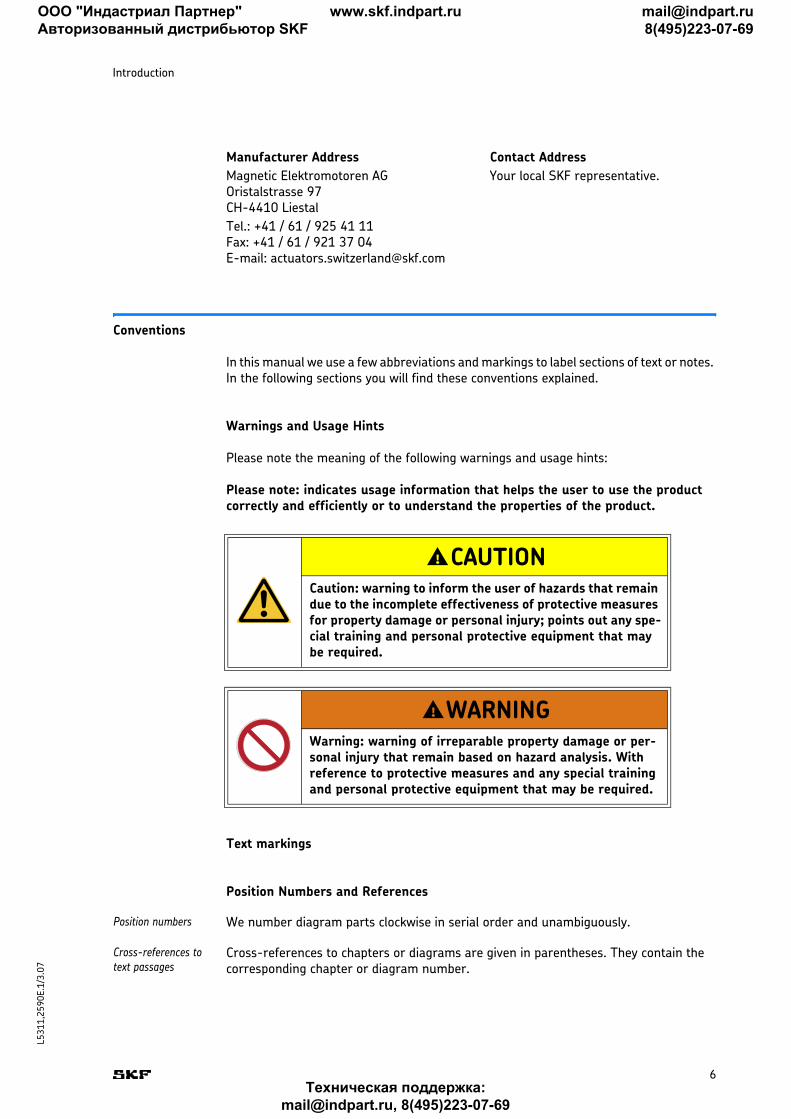
Please note the meaning of the following warnings and usage hints:
Please note: indicates usage information that helps the user to use the product correctly and efficiently or to understand the properties of the product.
Text markings
Position Numbers and References
Position numbers We number diagram parts clockwise in serial order and unambiguously.
Cross-references to text passages
Cross-references to chapters or diagrams are given in parentheses. They contain the corresponding chapter or diagram number.
Manufacturer Address Contact Address
Magnetic Elektromotoren AG Oristalstrasse 97 CH-4410 Liestal
Your local SKF representative.
Tel.: +41 / 61 / 925 41 11 Fax: +41 / 61 / 921 37 04 E-mail: [email protected]
CAUTIONCaution: warning to inform the user of hazards that remain due to the incomplete effectiveness of protective measures for property damage or personal injury; points out any spe-cial training and personal protective equipment that may be required.
WARNINGWarning: warning of irreparable property damage or per-sonal injury that remain based on hazard analysis. With reference to protective measures and any special training and personal protective equipment that may be required.
!
!
ООО "Индастриал Партнер"
Авторизованный дистрибьютор SKF
www.skf.indpart.ru [email protected]
8(495)223-07-69
Техническая поддержка:
[email protected], 8(495)223-07-69
L5
31
1,2
59
0E
.1/3.0
7
Introduction
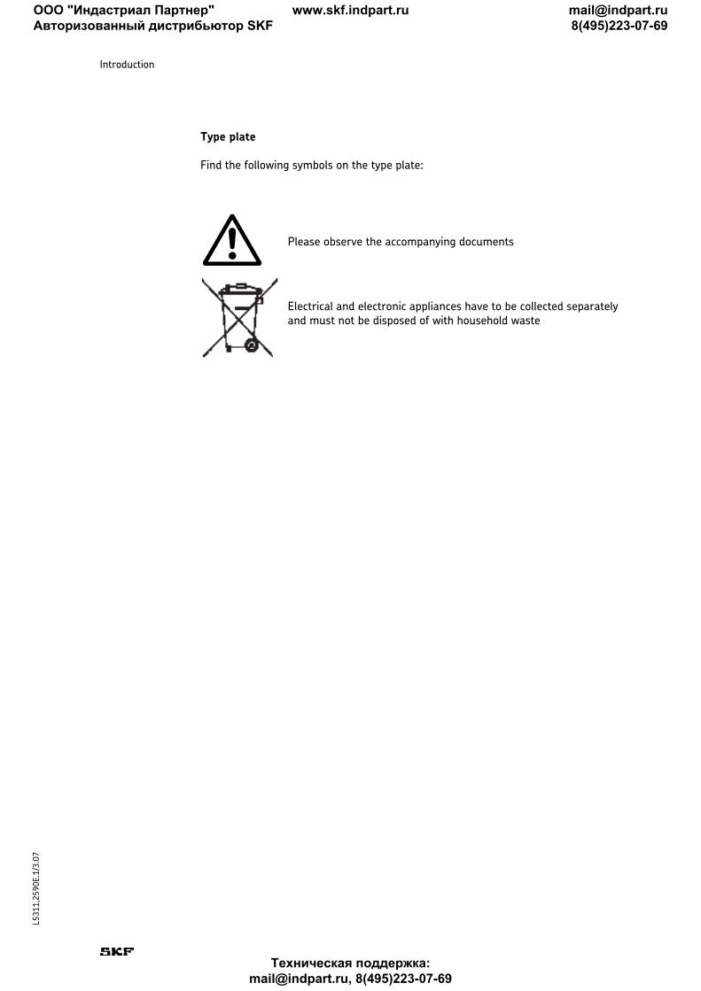
Type plate
Find the following symbols on the type plate:
Please observe the accompanying documents
Electrical and electronic appliances have to be collected separately and must not be disposed of with household waste
ООО "Индастриал Партнер"
Авторизованный дистрибьютор SKF
www.skf.indpart.ru [email protected]
8(495)223-07-69
Техническая поддержка:
[email protected], 8(495)223-07-69
8
L5
31
1,2
59
0E
.1/3.0
7
2. Safety
This chapter is intended for all users of the MAGDRIVE™ linear actuator. It contains information on its safe use and optimal utilization.
Safety Program
The safety program from Magnetic Elektromotoren AG spells out who is entitled to use it and the responsibility of individual users.
The MAGDRIVE™ was designed and built in accordance with the latest technical stan-dards and accepted safety rules.
CE-conformity is documented with the technical documentation.
Purpose of the MAGDRIVE™
The linear actuator MAGDRIVE™ has been designed and built to be operated in accor-dance with its intended use. If you use the MAGDRIVE™ for any use other than that cited, the manufacturer cannot be held responsible for damage resulting from this.
The MAGDRIVE™ has been designed for interior applications in the industrial, medical and building services engineering sectors.
Intended Use
The intended use of the MAGDRIVE™ is:
■ MD22/24: dynamically centered pressured lifting■ MD23/25: dynamically centered pressured or tension-stressed lifting
Please note: For the operations data, please see the Appendix of this operating manual (see Equipment and operating data, page 29) and associated datasheets.
Unauthorized Use
Any use other than the intended use without the manufacturer's written agreement or operation beyond the technical limits is considered unauthorized.
You can find the technical operating limits in the appendix (Technical data, page 29) of this manual, the associated datasheets and on the type plate of the MAGDRIVE™.
Please note: Any unauthorized use of the MAGDRIVE™ can cause personal injury and property damage. Always adhere to the instructions of this manual.
ООО "Индастриал Партнер"
Авторизованный дистрибьютор SKF
www.skf.indpart.ru [email protected]
8(495)223-07-69
Техническая поддержка:
[email protected], 8(495)223-07-69
9
L5
31
1,2
59
0E
.1/3.0
7
Safety
User groups
To ensure safety, we place requirements on the users of the MAGDRIVE™ that must be adhered to under all circumstances. Only persons who meet the requirements are enti-tled to use the MAGDRIVE™.
We refer to all persons who operate, use, commission the linear actuator, process it fur-ther or pass it on for further processing as user groups. As the requirements of these user groups strongly depend on their role, we distinguish between the following user groups:
Operating Authority The operating authority is the contractual partner of the person doing the further pro-cessing or the reseller. They can impose legal conditions on the operating authority when purchasing the linear actuator. The operating authority ensures that the user is instructed in the authorized use of the equipment.
Processor The processor is the contractual partner of the reseller or the manufacturer. He assem-bles the linear actuator into a complete device. He is authorized by the manufacturer to use the linear actuator MAGDRIVE™ in accordance with the regulations and has the nec-essary expert knowledge.
Technician The technician has the professional technical training to utilize the linear actuator MAGDRIVE™ according to its authorized use. Apart from the chapter on Safety, he is also familiar with the chapter on Special operating modes. He will find the required technical data in the Appendix.
Reseller The reseller forwards the machine.
Operator Any other person who uses the MAGDRIVE™ is defined as an operator. The operator must have read the Safety chapter in this manual before using the machine. Moreover, he must be instructed about normal operation by the operating authority.
Types of Operation
intermittent The linear actuator MAGDRIVE™ is only to be used for intermittent operation (refer to Technical data, page 29 or associated datasheets).
Danger Zones
We differentiate between two danger zones that must be observed, depending on the user role.
Persons The danger zone covering persons also includes, in addition to the actual user, third per-sons (other personnel, visitors, patients etc.). In case of injury, the operating authority is liable.
Device The danger zone device comes under the Processor and Technician user groups and cov-ers the linear actuator MAGDRIVE™ and any elements that have been attached.
Areas of Responsibility
Different areas of responsibility, corresponding to the different user groups, arise.
ООО "Индастриал Партнер"
Авторизованный дистрибьютор SKF
www.skf.indpart.ru [email protected]
8(495)223-07-69
Техническая поддержка:
[email protected], 8(495)223-07-69
10
L5
31
1,2
59
0E
.1/3.0
7
Safety
Operating Authority The operating authority bears the responsibility for the danger zone covering persons and ensures that only authorized and trained users work with the MAGDRIVE™. He or she is responsible for the following:
■ Identifying the persons who are allowed to use the MAGDRIVE™ (authorized per-sons)
■ Instructing the user groups■ Complying with all relevant legal conditions and regulations
Please note: The operating authority may only authorize persons to use the MAGDRIVE™ who meet the requirements for the user groups.
Processor The processor is responsible for the following:
■ Forwarding am CE-conformant operating manual for the device in which the lin-ear actuator MAGDRIVE™ is installed
■ Adherence to the safety regulations in accordance with this operating manual
Reseller The reseller is responsible for the following:
■ Forwarding this operating manual and the linear actuator MAGDRIVE™ to the processor or
■ forwarding an CE-conformant operating manual and the device in which the lin-ear actuator MAGDRIVE™ is installed to the operating authority
Technician The technician is responsible for the following:
■ Observing the manufacturer's instructions and the safe set-up of interfaces with other equipment.
■ Installation and use of the MAGDRIVE™ in accordance with its intended use■ Installation of optional modules and connecting cables
Operator The operator ensures that nobody will be endangered when the MAGDRIVE™ is running. He or she is, in particular, responsible for:
■ Operating the MAGDRIVE™ in normal operating conditions■ Immediate and appropriate reaction to malfunctions
General safety notice
The linear actuator is suitable for internal use only and must not be exposed to weath-ering, strong UV radiation or corrosive or explosive atmospheric media, or other aggres-sive media (see Appendix Ambient conditions, page 29 and associated datasheets).
Other hazards
The manufacturer has constructively, and with protective measures, minimized the effects of existing residual hazards. Pay attention to the residual hazards and the poten-tial countermeasures given in the following chapters.
ООО "Индастриал Партнер"
Авторизованный дистрибьютор SKF
www.skf.indpart.ru [email protected]
8(495)223-07-69
Техническая поддержка:
[email protected], 8(495)223-07-69
11
L5
31
1,2
59
0E
.1/3.0
7
Safety
Residual hazards to people, objects and property
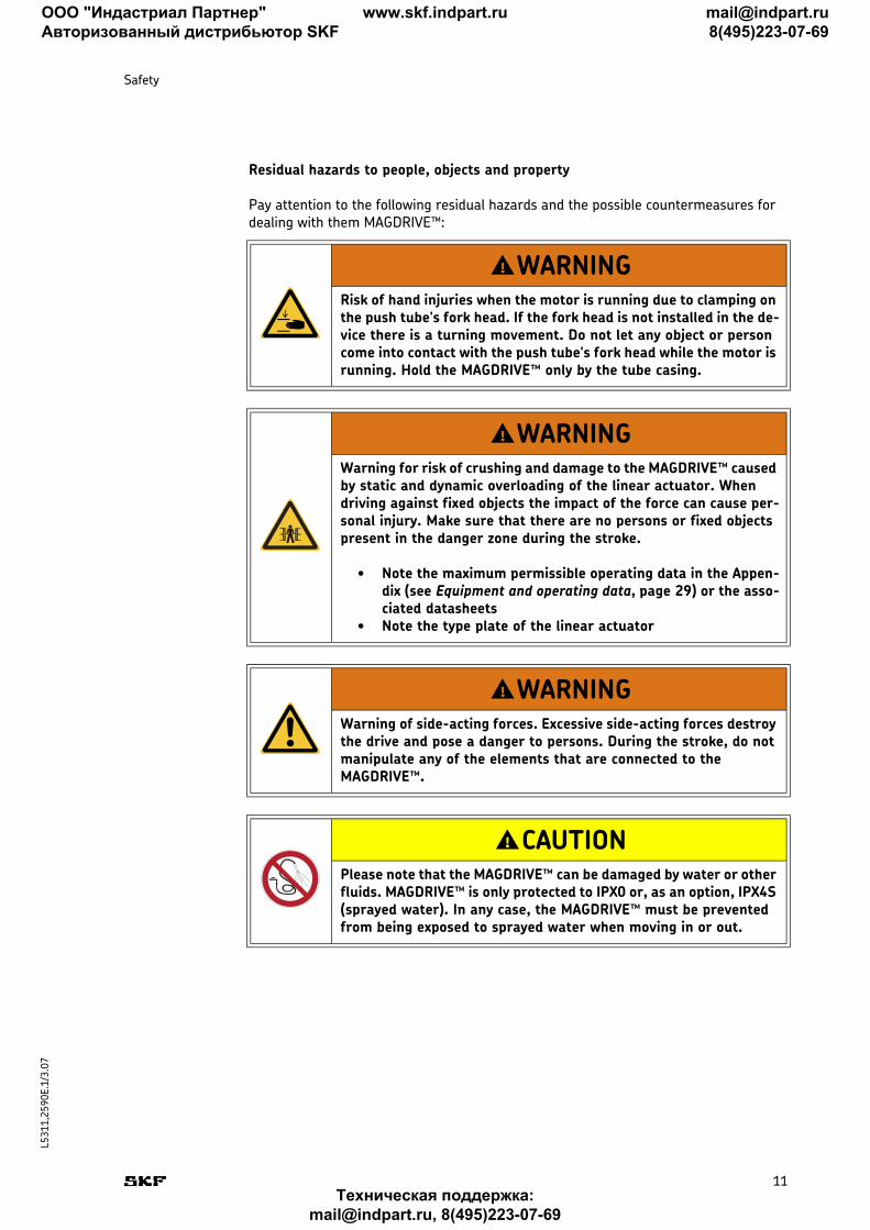
Pay attention to the following residual hazards and the possible countermeasures for dealing with them MAGDRIVE™:
WARNINGRisk of hand injuries when the motor is running due to clamping on the push tube's fork head. If the fork head is not installed in the de-vice there is a turning movement. Do not let any object or person come into contact with the push tube's fork head while the motor is running. Hold the MAGDRIVE™ only by the tube casing.
WARNINGWarning for risk of crushing and damage to the MAGDRIVE™ caused by static and dynamic overloading of the linear actuator. When driving against fixed objects the impact of the force can cause per-sonal injury. Make sure that there are no persons or fixed objects present in the danger zone during the stroke.
• Note the maximum permissible operating data in the Appen-dix (see Equipment and operating data, page 29) or the asso-ciated datasheets
• Note the type plate of the linear actuator
WARNINGWarning of side-acting forces. Excessive side-acting forces destroy the drive and pose a danger to persons. During the stroke, do not manipulate any of the elements that are connected to the MAGDRIVE™.
CAUTIONPlease note that the MAGDRIVE™ can be damaged by water or other fluids. MAGDRIVE™ is only protected to IPX0 or, as an option, IPX4S (sprayed water). In any case, the MAGDRIVE™ must be prevented from being exposed to sprayed water when moving in or out.
!
!
!
!
ООО "Индастриал Партнер"
Авторизованный дистрибьютор SKF
www.skf.indpart.ru [email protected]
8(495)223-07-69
Техническая поддержка:
[email protected], 8(495)223-07-69
12
L5
31
1,2
59
0E
.1/3.0
7
Safety
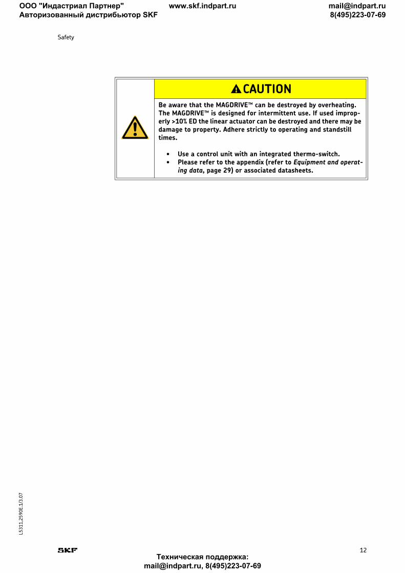
CAUTIONBe aware that the MAGDRIVE™ can be destroyed by overheating. The MAGDRIVE™ is designed for intermittent use. If used improp-erly >10% ED the linear actuator can be destroyed and there may be damage to property. Adhere strictly to operating and standstill times.
• Use a control unit with an integrated thermo-switch.• Please refer to the appendix (refer to Equipment and operat-
ing data, page 29) or associated datasheets.
!
ООО "Индастриал Партнер"
Авторизованный дистрибьютор SKF
www.skf.indpart.ru [email protected]
8(495)223-07-69
Техническая поддержка:
[email protected], 8(495)223-07-69
13
L5
31
1,2
59
0E
.1/3.0
7
3. Structure and Function
This chapter is intended for all users of the MAGDRIVE™. It shows its construction and explains its function.
Construction
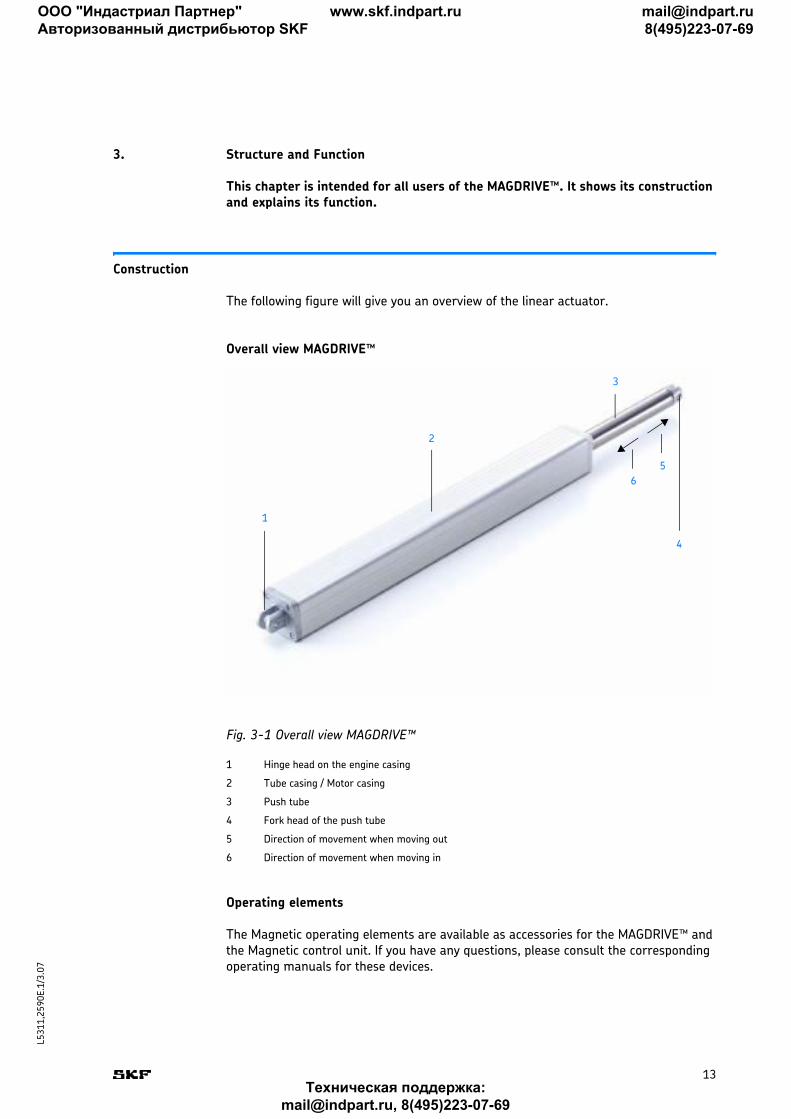
The following figure will give you an overview of the linear actuator.
Overall view MAGDRIVE™
Fig. 3-1 Overall view MAGDRIVE™
Operating elements
The Magnetic operating elements are available as accessories for the MAGDRIVE™ and the Magnetic control unit. If you have any questions, please consult the corresponding operating manuals for these devices.
1 Hinge head on the engine casing
2 Tube casing / Motor casing
3 Push tube
4 Fork head of the push tube
5 Direction of movement when moving out
6 Direction of movement when moving in
1
2
4
3
5
6
ООО "Индастриал Партнер"
Авторизованный дистрибьютор SKF
www.skf.indpart.ru [email protected]
8(495)223-07-69
Техническая поддержка:
[email protected], 8(495)223-07-69
14
L5
31
1,2
59
0E
.1/3.0
7
Structure and Function
Function
A description of its function allows you to understand what the linear actuator and its individual parts do.
Functional principles
The operating principle of the linear actuator MAGDRIVE™ MD22/24 is based on pres-sure only (tension stress is only permitted for transport purposes and limited in line with operating data (refer to Equipment and operating data, page 29 and/or associated datasheets).
The operating principle of the linear actuator MAGDRIVE™ MD23/25 is based on tension stress or pressure. MD23/25 must not be operated with alternating load (refer to Equip-ment and operating data, page 29 and/or associated datasheets).
The built-in brake decelerates the movement or holds the position at a standstill (refer to Fig. 3-1, page 13, Pos. 5 and 6). No lateral pressure or turning movement may be caused.
The linear drive MAGDRIVE™ must be equipped with a Magnetic control unit and oper-ating unit.
Tube casing / motor casing (2)
The tube casing / motor casing as the load-bearing component with an integrated engine, gear and linear unit. The power cable (motor cable with low-voltage plug) is firmly installed in the tube casing / motor housing. At the lower end of the tube casing a hinge head is fixed; this is used to move the actuator to the application on one side.
Motor unit The permanent magnet motor is a 24 V DC motor that drives the planetary gear via the motor shaft. The speed of the thrust depends on the load.
Drives The planetary gear is driven directly by the motor shaft which moves a worm gear.
Linear unit The linear unit / the push tube is integrated into the tube casing / motor casing. The worm gear converts the gear's turning movement via the spindle nut into a linear move-ment. If the spindle nut breaks an integrated safety nut protects the push tube from also breaking. An in and out movement is executed via the push tube. The push tube is surrounded by the tube casing / motor casing (2) and protected by it. The base of the push tube is connected with the worm gear via the spindle nut, at the top is the fork head (4) of the push tube (3).
Thermo-switch The linear drive MAGDRIVE™ does not have any thermal protection and can be damaged by overheating. For this reason a control unit with an integrated thermo-switch must be used. This switches the MAGDRIVE™ off in an emergency. The linear actuator must not be operated until the drive temperature has fallen below the switching threshold.
Brake The brake is attached to the spindle, its purpose is to decelerate the worm gear and sup-port the self locking.
End switch The linear actuator is equipped with internal end switches that switch off the linear actu-ator at the end positions. If the end switches fail the linear actuator moves to one of the two buffers attached to each side if a serious error occurs, blocks and releases the cur-rent cut off integrated into the control unit or removes the power from the linear actu-ator.
ООО "Индастриал Партнер"
Авторизованный дистрибьютор SKF
www.skf.indpart.ru [email protected]
8(495)223-07-69
Техническая поддержка:
[email protected], 8(495)223-07-69
15
L5
31
1,2
59
0E
.1/3.0
7
Structure and Function
Options and accessories
Options
Options can be recognized from the type designation on the type plate.
Emergency lowering For applications where lowering takes place mechanically in an emergency it is possible to equip the linear actuator with an optional emergency lowering device. Then it is pos-sible, if for example the power fails or there are drive errors, to lower the application manually (refer also to the Emergency Shutdown, page 17) section.
Electrical anti pinching protection
The electrical anti pinching protection is an electrical switch that switches the linear actuator off when moving in (6) if the stroke is hindered by an object or body part. This protection does not work when moving out (5).
Encoder With the Hall sensor, the encoder picks up impulses from a magnetic disk located on the motor shaft.
IPX4S The linear actuator MAGDRIVE™ may be supplied as an option with protection class IPX4S. This protects the MAGDRIVE™ against sprayed water (refer to 4. Normal Opera-tion, page 16).
Accessories
Control unit The linear actuator MAGDRIVE™ requires a Magnetic control unit to power the motor. Only use Magnetic control units.
Operating elements The linear actuator MAGDRIVE™ can be operated remotely by a Magnetic operating ele-ment on the control unit. Only use Magnetic operating elements.
Important: Magnetic Elektromotoren AG will not accept liability for any damage caused if the linear actuator MAGDRIVE™ is not used with a suitable Magnetic con-trol unit / operating element.
ООО "Индастриал Партнер"
Авторизованный дистрибьютор SKF
www.skf.indpart.ru [email protected]
8(495)223-07-69
Техническая поддержка:
[email protected], 8(495)223-07-69
16
L5
31
1,2
59
0E
.1/3.0
7
Normal Operation
4. Normal Operation
This chapter is directed at the user groups operator and operating authority. It pro-vides all the information required for the safe and smooth operation of the linear actuator under normal operating conditions.
Normal Operation
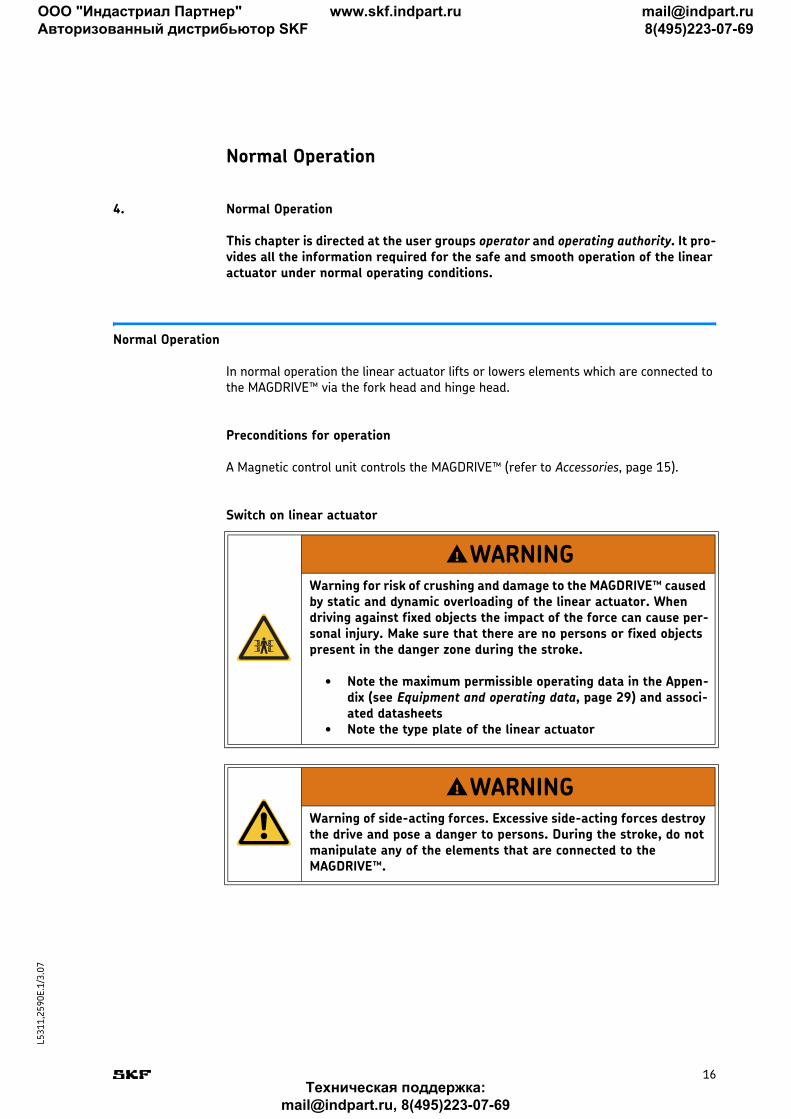
In normal operation the linear actuator lifts or lowers elements which are connected to the MAGDRIVE™ via the fork head and hinge head.
Preconditions for operation
A Magnetic control unit controls the MAGDRIVE™ (refer to Accessories, page 15).
Switch on linear actuator
WARNINGWarning for risk of crushing and damage to the MAGDRIVE™ caused by static and dynamic overloading of the linear actuator. When driving against fixed objects the impact of the force can cause per-sonal injury. Make sure that there are no persons or fixed objects present in the danger zone during the stroke.
• Note the maximum permissible operating data in the Appen-dix (see Equipment and operating data, page 29) and associ-ated datasheets
• Note the type plate of the linear actuator
WARNINGWarning of side-acting forces. Excessive side-acting forces destroy the drive and pose a danger to persons. During the stroke, do not manipulate any of the elements that are connected to the MAGDRIVE™.
!
!
ООО "Индастриал Партнер"
Авторизованный дистрибьютор SKF
www.skf.indpart.ru [email protected]
8(495)223-07-69
Техническая поддержка:
[email protected], 8(495)223-07-69
17
L5
31
1,2
59
0E
.1/3.0
7
Normal Operation
The Magnetic control unit must be connected to mains electricity. It is operated by a Magnetic operating element (see Accessories, page 15).
Emergency lowering For applications with emergency lowering in special cases, such as power failure or oper-ational defects, it may be desirable to lower the load manually.
Please note: Excessive use of effort or an independent downward movement indi-cate a damaged actuator. The MAGDRIVE™ must not be run any more. Immediately inform the manufacturer that performs the inspection.
Emergency Shutdown
1 Pull out the plug of the cable that connects the linear actuator to the control unit.
Please note: The MAGDRIVE™does not have an on / off switch and must be sepa-rated from the power supply to the control unit. Only this measure will de-energize the MAGDRIVE™.
Patient lifters An emergency off switch is essential for patient lifters.
Please note: The emergency shut-off switch must be fitted by the executor.
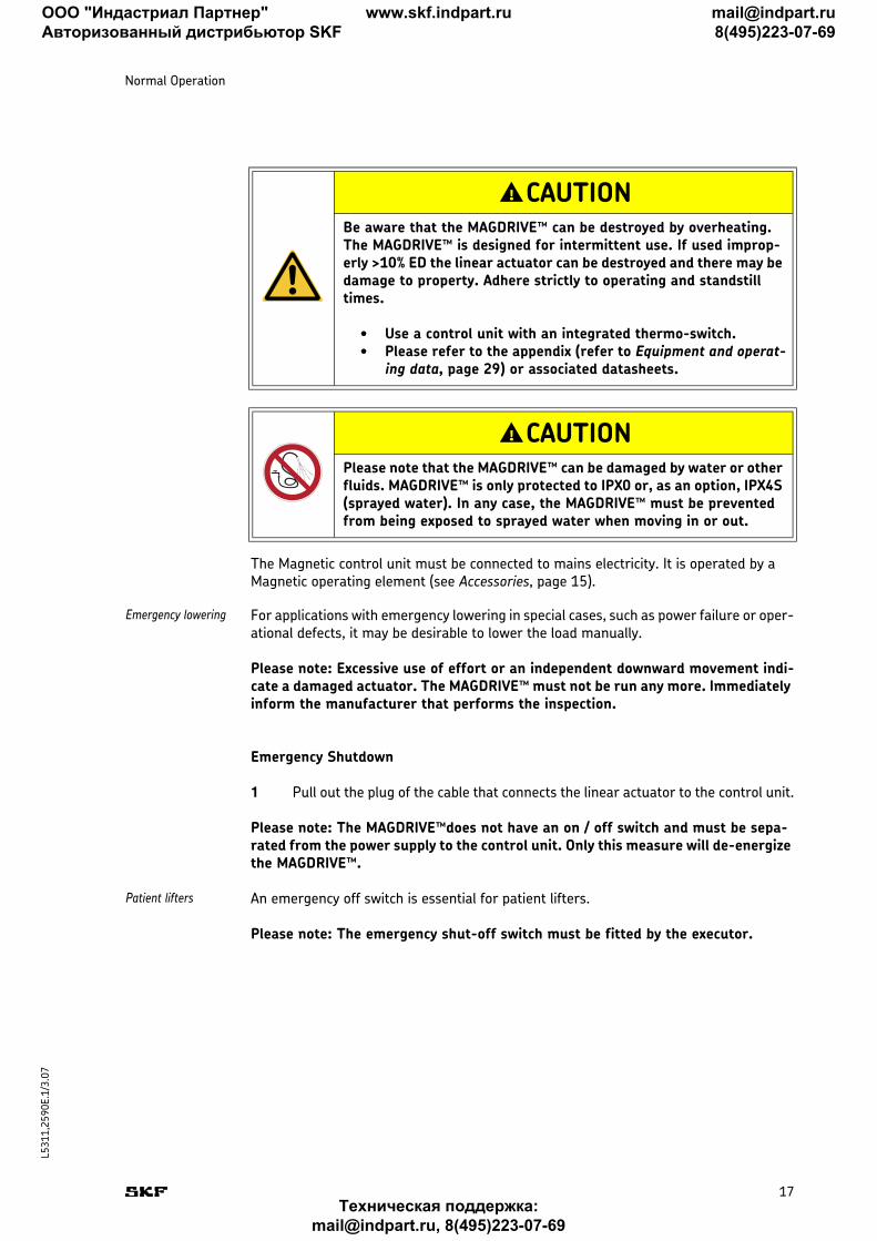
CAUTIONBe aware that the MAGDRIVE™ can be destroyed by overheating. The MAGDRIVE™ is designed for intermittent use. If used improp-erly >10% ED the linear actuator can be destroyed and there may be damage to property. Adhere strictly to operating and standstill times.
• Use a control unit with an integrated thermo-switch.• Please refer to the appendix (refer to Equipment and operat-
ing data, page 29) or associated datasheets.
CAUTIONPlease note that the MAGDRIVE™ can be damaged by water or other fluids. MAGDRIVE™ is only protected to IPX0 or, as an option, IPX4S (sprayed water). In any case, the MAGDRIVE™ must be prevented from being exposed to sprayed water when moving in or out.
!
!
ООО "Индастриал Партнер"
Авторизованный дистрибьютор SKF
www.skf.indpart.ru [email protected]
8(495)223-07-69
Техническая поддержка:
[email protected], 8(495)223-07-69
18
L5
31
1,2
59
0E
.1/3.0
7
Special Operations
The following chapters are part of the special operations:
■ 5. Installation and Initial Start-Up, page 18■ 6. Maintenance, Clearing malfunctions, Repairs, page 22■ 7. Removing from service, dismantling and disposal, page 27
5. Installation and Initial Start-Up
This chapter is intended for technicians and those doing the further processing. It provides all the information that you need to assemble, connect and start up the linear actuator MAGDRIVE™.
Preparation
Good preparation is part of efficient installation and start-up. This includes, among other things, deciding on a location and having an energy source ready.
Transport
Please note: The linear actuator must be examined for damage on delivery. Any transit damage is to be notified to the carrier and the manufacturer immediately and in writing.
The linear actuator MAGDRIVE™ is delivered as a unit in a box or on pallets. Instruct a carrier to ship the linear actuator.
Return to the manufac-turer
Prepare the linear actuator for transport as follows:
1 Dismantle the linear actuator (refer to Dismantling, page 27)
2 Pack the linear actuator carefully.
Please note: the storage conditions also apply to the transport (refer to Storage, page 27). You can find important information on weight, dimensions etc. in the technical data in the appendix (Technical data, page 29) and the associated datasheets.
Check items in shipment
The linear actuator comprises:
■ a complete actuator unit comprising drive, motor and linear unit■ a cable with a low-voltage plug
ООО "Индастриал Партнер"
Авторизованный дистрибьютор SKF
www.skf.indpart.ru [email protected]
8(495)223-07-69
Техническая поддержка:
[email protected], 8(495)223-07-69
19
L5
31
1,2
59
0E
.1/3.0
7
Installation and Initial Start-Up
Power supply
The linear actuator MAGDRIVE™ runs solely on electricity. Observe the connection values in the appendix of this manual (chapter Equipment and operating data, page 29) or the associated datasheets.
Installation and Connections
Installing the linear actuator MAGDRIVE™ on other elements involves taking into account special requirements of different applications.
The linear actuator MAGDRIVE™ is fixed to two elements via the fork head and hinge head.
The following sections show how to set up and align the linear actuator MAGDRIVE™, as well as the interfaces and connections.
Set-up and Adjustment
In setting up and aligning the linear actuator MAGDRIVE™ the following points must be observed.
Make sure that
■ the fork head and hinge head and the application elements are connected with fastening bolts (only use fastening bolts! Screws and such like may not be used due to pre-tensioning, poor positioning or flexing).
■ the acting force also works centrally on the push tube (lateral forces or those that exert a torque on the linear unit can destroy the linear actuator),
■ the linear actuator is not obstructed in any way in the entire stroke area.■ the cables are not pinched or caught or subject to tension stress,■ you never loosen screws on the MAGDRIVE™ or try to open the linear drive
MAGDRIVE™ (Magnetic Elektromotoren AG rejects all warranty claims if screws on the MAGDRIVE™ have been manipulated).
Interfaces and Connections
You can find the nominal values in the appendix (section Technical data, page 29) or associated datasheets. Check that all interfaces and connections have been mounted and/or connected correctly.
■ Interfaces for the application fixed to the fork head and hinge head■ Connection to an appropriate control unit (refer to Accessories, page 15)■ Connection to an appropriate operating unit (refer to Accessories, page 15)
ООО "Индастриал Партнер"
Авторизованный дистрибьютор SKF
www.skf.indpart.ru [email protected]
8(495)223-07-69
Техническая поддержка:
[email protected], 8(495)223-07-69
20
L5
31
1,2
59
0E
.1/3.0
7
Installation and Initial Start-Up
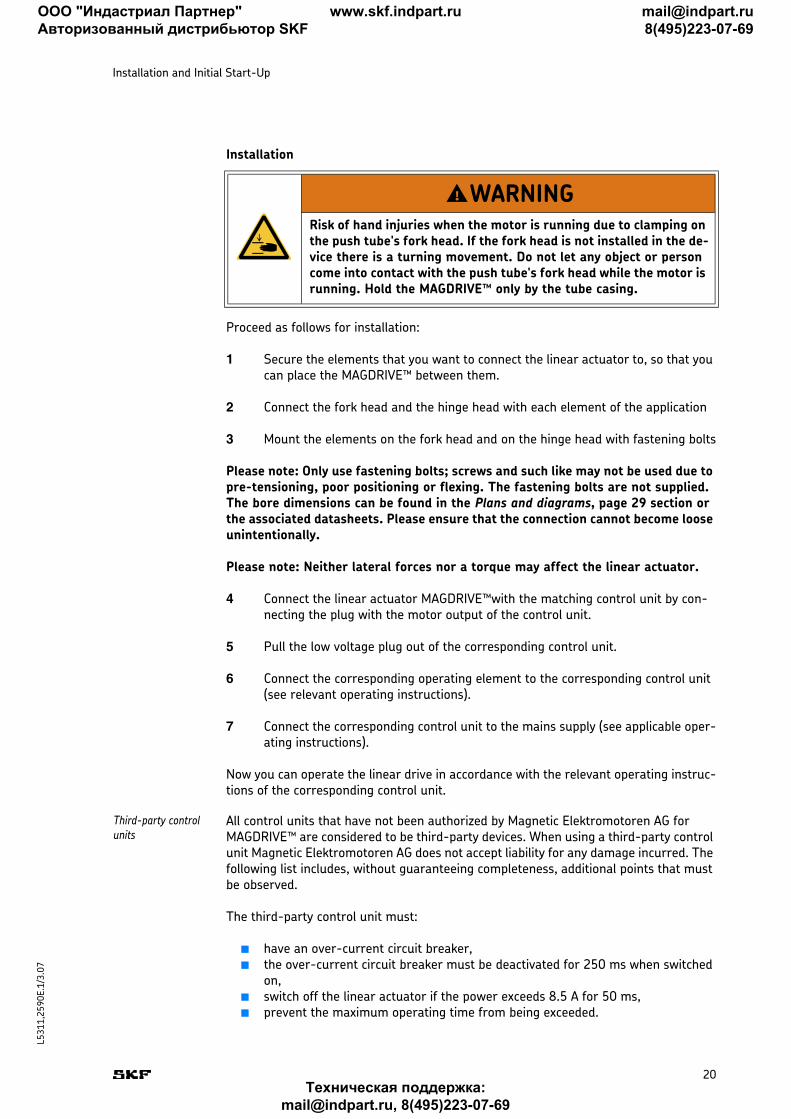
Installation
Proceed as follows for installation:
1 Secure the elements that you want to connect the linear actuator to, so that you can place the MAGDRIVE™ between them.
2 Connect the fork head and the hinge head with each element of the application
3 Mount the elements on the fork head and on the hinge head with fastening bolts
Please note: Only use fastening bolts; screws and such like may not be used due to pre-tensioning, poor positioning or flexing. The fastening bolts are not supplied. The bore dimensions can be found in the Plans and diagrams, page 29 section or the associated datasheets. Please ensure that the connection cannot become loose unintentionally.
Please note: Neither lateral forces nor a torque may affect the linear actuator.
4 Connect the linear actuator MAGDRIVE™with the matching control unit by con-necting the plug with the motor output of the control unit.
5 Pull the low voltage plug out of the corresponding control unit.
6 Connect the corresponding operating element to the corresponding control unit (see relevant operating instructions).
7 Connect the corresponding control unit to the mains supply (see applicable oper-ating instructions).
Now you can operate the linear drive in accordance with the relevant operating instruc-tions of the corresponding control unit.
Third-party control units
All control units that have not been authorized by Magnetic Elektromotoren AG for MAGDRIVE™ are considered to be third-party devices. When using a third-party control unit Magnetic Elektromotoren AG does not accept liability for any damage incurred. The following list includes, without guaranteeing completeness, additional points that must be observed.
The third-party control unit must:
■ have an over-current circuit breaker,■ the over-current circuit breaker must be deactivated for 250 ms when switched
on,■ switch off the linear actuator if the power exceeds 8.5 A for 50 ms,■ prevent the maximum operating time from being exceeded.
WARNINGRisk of hand injuries when the motor is running due to clamping on the push tube's fork head. If the fork head is not installed in the de-vice there is a turning movement. Do not let any object or person come into contact with the push tube's fork head while the motor is running. Hold the MAGDRIVE™ only by the tube casing.
!
ООО "Индастриал Партнер"
Авторизованный дистрибьютор SKF
www.skf.indpart.ru [email protected]
8(495)223-07-69
Техническая поддержка:
[email protected], 8(495)223-07-69
21
L5
31
1,2
59
0E
.1/3.0
7
Installation and Initial Start-Up
Initial Start-Up
Perform the installation check before you start up the linear actuator for the first time MAGDRIVE™.
Installation Check
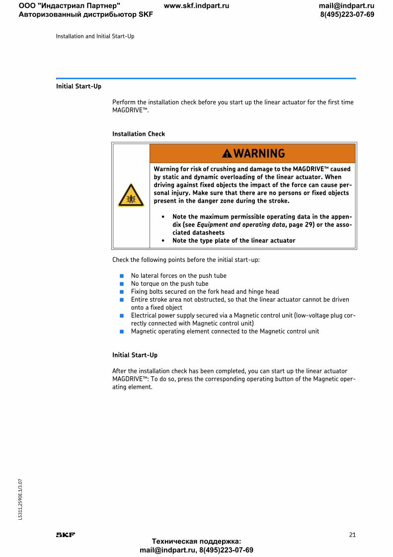
Check the following points before the initial start-up:
■ No lateral forces on the push tube■ No torque on the push tube■ Fixing bolts secured on the fork head and hinge head ■ Entire stroke area not obstructed, so that the linear actuator cannot be driven
onto a fixed object■ Electrical power supply secured via a Magnetic control unit (low-voltage plug cor-
rectly connected with Magnetic control unit)■ Magnetic operating element connected to the Magnetic control unit
Initial Start-Up
After the installation check has been completed, you can start up the linear actuator MAGDRIVE™: To do so, press the corresponding operating button of the Magnetic oper-ating element.
WARNINGWarning for risk of crushing and damage to the MAGDRIVE™ caused by static and dynamic overloading of the linear actuator. When driving against fixed objects the impact of the force can cause per-sonal injury. Make sure that there are no persons or fixed objects present in the danger zone during the stroke.
• Note the maximum permissible operating data in the appen-dix (see Equipment and operating data, page 29) or the asso-ciated datasheets
• Note the type plate of the linear actuator
!
ООО "Индастриал Партнер"
Авторизованный дистрибьютор SKF
www.skf.indpart.ru [email protected]
8(495)223-07-69
Техническая поддержка:
[email protected], 8(495)223-07-69
22
L5
31
1,2
59
0E
.1/3.0
7
6. Maintenance, Clearing malfunctions, Repairs
This chapter is intended for technicians and those doing the further processing. It provides you with all the information you need for maintaining, clearing malfunc-tions and carrying out repairs on the linear actuator MAGDRIVE™.
Maintenance
Maintenance includes all operations which keep the linear actuator fully functional. These operations include inspections, replacing consumables and cleaning.
Maintenance plan
The linear actuator MAGDRIVE™ is virtually maintenance-free for the full duration of its service life (you can find details on its service life in the appendix, Equipment and oper-ating data, page 29). The connection cables and linear actuator have to be checked for wear and tear at regular intervals.
Cleaning
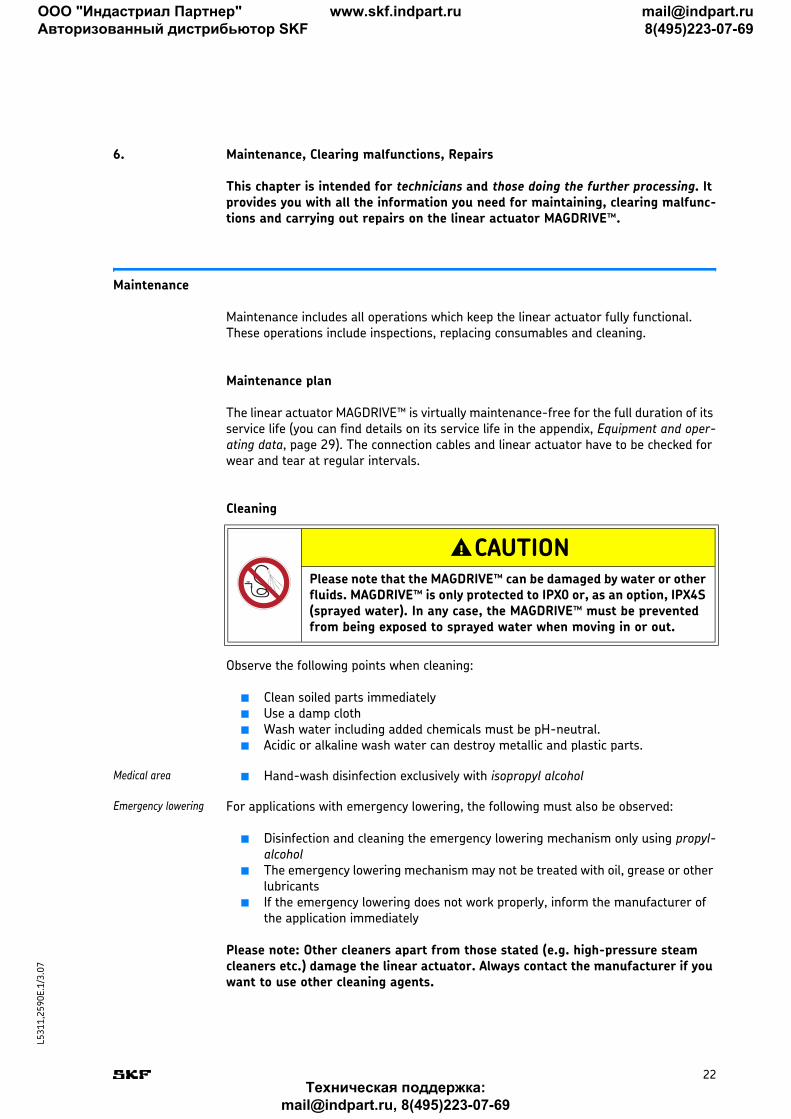
Observe the following points when cleaning:
■ Clean soiled parts immediately■ Use a damp cloth■ Wash water including added chemicals must be pH-neutral.■ Acidic or alkaline wash water can destroy metallic and plastic parts.
Medical area ■ Hand-wash disinfection exclusively with isopropyl alcohol
Emergency lowering For applications with emergency lowering, the following must also be observed:
■ Disinfection and cleaning the emergency lowering mechanism only using propyl-alcohol
■ The emergency lowering mechanism may not be treated with oil, grease or other lubricants
■ If the emergency lowering does not work properly, inform the manufacturer of the application immediately
Please note: Other cleaners apart from those stated (e.g. high-pressure steam cleaners etc.) damage the linear actuator. Always contact the manufacturer if you want to use other cleaning agents.
CAUTIONPlease note that the MAGDRIVE™ can be damaged by water or other fluids. MAGDRIVE™ is only protected to IPX0 or, as an option, IPX4S (sprayed water). In any case, the MAGDRIVE™ must be prevented from being exposed to sprayed water when moving in or out.
!
ООО "Индастриал Партнер"
Авторизованный дистрибьютор SKF
www.skf.indpart.ru [email protected]
8(495)223-07-69
Техническая поддержка:
[email protected], 8(495)223-07-69
23
L5
31
1,2
59
0E
.1/3.0
7
Maintenance, Clearing malfunctions, Repairs
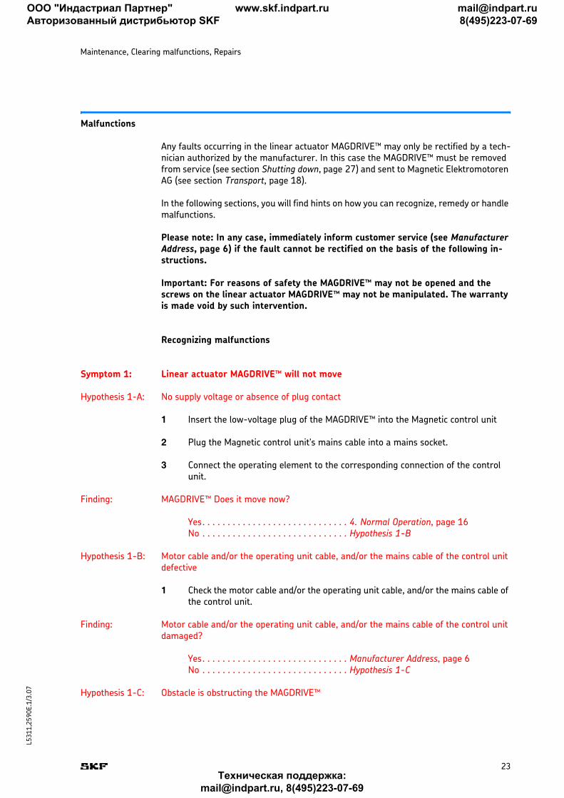
Malfunctions
Any faults occurring in the linear actuator MAGDRIVE™ may only be rectified by a tech-nician authorized by the manufacturer. In this case the MAGDRIVE™ must be removed from service (see section Shutting down, page 27) and sent to Magnetic Elektromotoren AG (see section Transport, page 18).
In the following sections, you will find hints on how you can recognize, remedy or handle malfunctions.
Please note: In any case, immediately inform customer service (see Manufacturer Address, page 6) if the fault cannot be rectified on the basis of the following in-structions.
Important: For reasons of safety the MAGDRIVE™ may not be opened and the screws on the linear actuator MAGDRIVE™ may not be manipulated. The warranty is made void by such intervention.
Recognizing malfunctions
Symptom 1: Linear actuator MAGDRIVE™ will not move
Hypothesis 1-A: No supply voltage or absence of plug contact
1 Insert the low-voltage plug of the MAGDRIVE™ into the Magnetic control unit
2 Plug the Magnetic control unit's mains cable into a mains socket.
3 Connect the operating element to the corresponding connection of the control unit.
Finding: MAGDRIVE™ Does it move now?
Yes. . . . . . . . . . . . . . . . . . . . . . . . . . . . . 4. Normal Operation, page 16No . . . . . . . . . . . . . . . . . . . . . . . . . . . . . Hypothesis 1-B
Hypothesis 1-B: Motor cable and/or the operating unit cable, and/or the mains cable of the control unit defective
1 Check the motor cable and/or the operating unit cable, and/or the mains cable of the control unit.
Finding: Motor cable and/or the operating unit cable, and/or the mains cable of the control unit damaged?
Yes. . . . . . . . . . . . . . . . . . . . . . . . . . . . . Manufacturer Address, page 6No . . . . . . . . . . . . . . . . . . . . . . . . . . . . . Hypothesis 1-C
Hypothesis 1-C: Obstacle is obstructing the MAGDRIVE™
ООО "Индастриал Партнер"
Авторизованный дистрибьютор SKF
www.skf.indpart.ru [email protected]
8(495)223-07-69
Техническая поддержка:
[email protected], 8(495)223-07-69
24
L5
31
1,2
59
0E
.1/3.0
7
Maintenance, Clearing malfunctions, Repairs
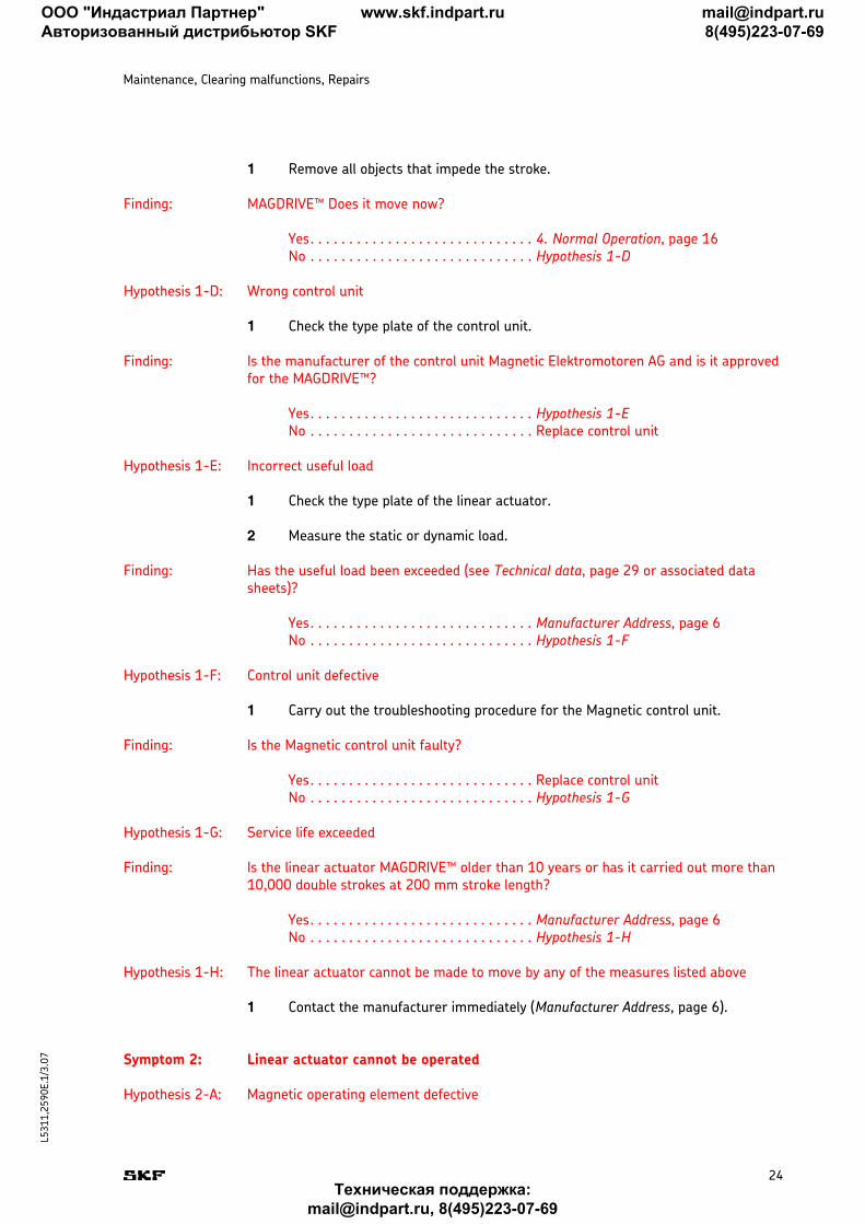
1 Remove all objects that impede the stroke.
Finding: MAGDRIVE™ Does it move now?
Yes. . . . . . . . . . . . . . . . . . . . . . . . . . . . . 4. Normal Operation, page 16No . . . . . . . . . . . . . . . . . . . . . . . . . . . . . Hypothesis 1-D
Hypothesis 1-D: Wrong control unit
1 Check the type plate of the control unit.
Finding: Is the manufacturer of the control unit Magnetic Elektromotoren AG and is it approved for the MAGDRIVE™?
Yes. . . . . . . . . . . . . . . . . . . . . . . . . . . . . Hypothesis 1-ENo . . . . . . . . . . . . . . . . . . . . . . . . . . . . . Replace control unit
Hypothesis 1-E: Incorrect useful load
1 Check the type plate of the linear actuator.
2 Measure the static or dynamic load.
Finding: Has the useful load been exceeded (see Technical data, page 29 or associated data sheets)?
Yes. . . . . . . . . . . . . . . . . . . . . . . . . . . . . Manufacturer Address, page 6No . . . . . . . . . . . . . . . . . . . . . . . . . . . . . Hypothesis 1-F
Hypothesis 1-F: Control unit defective
1 Carry out the troubleshooting procedure for the Magnetic control unit.
Finding: Is the Magnetic control unit faulty?
Yes. . . . . . . . . . . . . . . . . . . . . . . . . . . . . Replace control unitNo . . . . . . . . . . . . . . . . . . . . . . . . . . . . . Hypothesis 1-G
Hypothesis 1-G: Service life exceeded
Finding: Is the linear actuator MAGDRIVE™ older than 10 years or has it carried out more than 10,000 double strokes at 200 mm stroke length?
Yes. . . . . . . . . . . . . . . . . . . . . . . . . . . . . Manufacturer Address, page 6No . . . . . . . . . . . . . . . . . . . . . . . . . . . . . Hypothesis 1-H
Hypothesis 1-H: The linear actuator cannot be made to move by any of the measures listed above
1 Contact the manufacturer immediately (Manufacturer Address, page 6).
Symptom 2: Linear actuator cannot be operated
Hypothesis 2-A: Magnetic operating element defective
ООО "Индастриал Партнер"
Авторизованный дистрибьютор SKF
www.skf.indpart.ru [email protected]
8(495)223-07-69
Техническая поддержка:
[email protected], 8(495)223-07-69
25
L5
31
1,2
59
0E
.1/3.0
7
Maintenance, Clearing malfunctions, Repairs
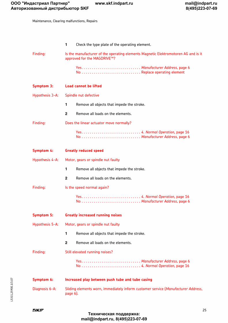
1 Check the type plate of the operating element.
Finding: Is the manufacturer of the operating elements Magnetic Elektromotoren AG and is it approved for the MAGDRIVE™?
Yes. . . . . . . . . . . . . . . . . . . . . . . . . . . . . Manufacturer Address, page 6No . . . . . . . . . . . . . . . . . . . . . . . . . . . . . Replace operating element
Symptom 3: Load cannot be lifted
Hypothesis 3-A: Spindle nut defective
1 Remove all objects that impede the stroke.
2 Remove all loads on the elements.
Finding: Does the linear actuator move normally?
Yes. . . . . . . . . . . . . . . . . . . . . . . . . . . . . 4. Normal Operation, page 16No . . . . . . . . . . . . . . . . . . . . . . . . . . . . . Manufacturer Address, page 6
Symptom 4: Greatly reduced speed
Hypothesis 4-A: Motor, gears or spindle nut faulty
1 Remove all objects that impede the stroke.
2 Remove all loads on the elements.
Finding: Is the speed normal again?
Yes. . . . . . . . . . . . . . . . . . . . . . . . . . . . . 4. Normal Operation, page 16No . . . . . . . . . . . . . . . . . . . . . . . . . . . . . Manufacturer Address, page 6
Symptom 5: Greatly increased running noises
Hypothesis 5-A: Motor, gears or spindle nut faulty
1 Remove all objects that impede the stroke.
2 Remove all loads on the elements.
Finding: Still elevated running noises?
Yes. . . . . . . . . . . . . . . . . . . . . . . . . . . . . Manufacturer Address, page 6No . . . . . . . . . . . . . . . . . . . . . . . . . . . . . 4. Normal Operation, page 16
Symptom 6: Increased play between push tube and tube casing
Diagnosis 6-A: Sliding elements worn, immediately inform customer service (Manufacturer Address, page 6).
ООО "Индастриал Партнер"
Авторизованный дистрибьютор SKF
www.skf.indpart.ru [email protected]
8(495)223-07-69
Техническая поддержка:
[email protected], 8(495)223-07-69
26
L5
31
1,2
59
0E
.1/3.0
7
Maintenance, Clearing malfunctions, Repairs
Repair
The linear actuator MAGDRIVE™ may only be opened by the manufacturer. In any case, contact customer service (Manufacturer Address, page 6).
Emergency lowering If excessive force is required for the turning movement or it is very easy to move under nominal load (i.e. independent lowering movement by linear actuator) the linear actua-tor may no longer be operated. The manufacturer must examine the linear actuator MAGDRIVE™. Immediately inform customer service (Manufacturer Address, page 6).
ООО "Индастриал Партнер"
Авторизованный дистрибьютор SKF
www.skf.indpart.ru [email protected]
8(495)223-07-69
Техническая поддержка:
[email protected], 8(495)223-07-69
27
L5
31
1,2
59
0E
.1/3.0
7
7. Removing from service, dismantling and disposal
This chapter is intended for technicians and those doing the further processing. It provides you with all the information needed to remove the linear actuator MAGDRIVE™ from service, dismantle it and dispose of it.
Shutting down
The linear actuator MAGDRIVE™ is to be removed from service in the following sequence:
1 De-energize the linear actuator by unplugging the mains plug of the control unit from the power outlet.
2 Secure the elements in such a way that there is no pulling or pushing force resting on the fork head and hinge head.
3 Loosen the lock that connects the low voltage plug of the MAGDRIVE™ with the Magnetic control unit.
4 Pull the low voltage plug out of the Magnetic control unit.
Afterwards you can dismantle or reinstall the MAGDRIVE™.
Dismantling
Before you start dismantling, put the linear actuator MAGDRIVE™ out of operation (see Shutting down, page 27). The linear actuator MAGDRIVE™ is to be dismantled in the fol-lowing sequence:
1 Ensure that there is no pressure acting on the fork head and hinge head.
2 Loosen the fastening bolts from the fastening bracket on the fork head and hinge head
3 Remove the fastening bolt
4 Separate the linear actuator from the elements
Afterwards, you can prepare the MAGDRIVE™ for shipping (see section Transport, page 18) or store or dispose of it as described in the following sections.
Storage
For storage, pack the MAGDRIVE™ in its original packaging. Observe the following values when selecting a storage location:
■ Ambient temperature: -10 °C to +40 °C■ Atmospheric humidity: up to 95%
ООО "Индастриал Партнер"
Авторизованный дистрибьютор SKF
www.skf.indpart.ru [email protected]
8(495)223-07-69
Техническая поддержка:
[email protected], 8(495)223-07-69
28
L5
31
1,2
59
0E
.1/3.0
7
Removing from service, dismantling and disposal
Disposal
The linear actuator is primarily made from recyclable materials. Specialized companies can separate the recyclable materials and therefore minimize the quantity of materials requiring disposal.
The linear actuator must be disposed of in a technically correct manner in accordance with local regulations. The plastic parts are marked with material specifications on the actual parts (except some of the smallest parts).
Please find dismantling instructions and shipping requirements in the relevant sections.
ООО "Индастриал Партнер"
Авторизованный дистрибьютор SKF
www.skf.indpart.ru [email protected]
8(495)223-07-69
Техническая поддержка:
[email protected], 8(495)223-07-69
29
L5
31
1,2
59
0E
.1/03.0
7
Appendix
8. Appendix
This chapter enables the user to find technical data, directories, diagrams and plans quickly.
Technical data
Equipment and operating data
The equipment and operating data can be found in the current datasheet.
■ Datasheet for MAGDRIVE™ (L5321,2590E)■ Datasheet for MAGDRIVE™ accessories (L5321,2591E)■ Datenblatt für MAGDRIVE™ Wintergarten (L5321,2592E)
Current datasheets are available on the website (see www.magnetic.skf.com).
Please note: The linear actuator MAGDRIVE™ is designed for a service life of 10 years or 10,000 double strokes at a stroke length of 200 mm (with authorized us-age).
Important: If the MAGDRIVE™ is operated beyond the defined operating values the operator must recalculate the life span from his own tests.
Ambient conditions
■ Temperature range: +10 °C to +40 °C■ Atmospheric humidity: 5% to 85%
The linear actuator is suitable for internal use only and must not be exposed to weath-ering, strong UV radiation or corrosive or explosive atmospheric media, or other aggres-sive media.
Plans and diagrams
To view the plans and diagrams, please contact the manufacturer (see Manufacturer Address, page 6). Further information can be found in the datasheet. Current datasheets are available on the website (see www.magnetic.skf.com).
ООО "Индастриал Партнер"
Авторизованный дистрибьютор SKF
www.skf.indpart.ru [email protected]
8(495)223-07-69
Техническая поддержка:
[email protected], 8(495)223-07-69
30
L5
31
1,2
59
0E
.1/3.0
7
Appendix
Standards applied
■ IEC 60601-1■ UL 60601-1
For further information, please contact the manufacturer (see Manufacturer Address, page 6).
ООО "Индастриал Партнер"
Авторизованный дистрибьютор SKF
www.skf.indpart.ru [email protected]
8(495)223-07-69
Техническая поддержка:
[email protected], 8(495)223-07-69
31
L5
31
1,2
59
0E
.1/3.0
7
iIndex
A Ambient conditions . . . . . . . . . . . . . . . . . . . . . . . . . . . . . . . . . . . . . . . . . . . . . . . . . . . 29Atmospheric humidity . . . . . . . . . . . . . . . . . . . . . . . . . . . . . . . . . . . . . . . . . . . . . . . . . 29
B Brake . . . . . . . . . . . . . . . . . . . . . . . . . . . . . . . . . . . . . . . . . . . . . . . . . . . . . . . . . . . . . 14
C Control unit . . . . . . . . . . . . . . . . . . . . . . . . . . . . . . . . . . . . . . . . . . . . . . . . . . . . . . . . . 15
D Drives . . . . . . . . . . . . . . . . . . . . . . . . . . . . . . . . . . . . . . . . . . . . . . . . . . . . . . . . . . . . . 14
E Electrical anti pinching protection . . . . . . . . . . . . . . . . . . . . . . . . . . . . . . . . . . . . . . . . 15Emergency lowering . . . . . . . . . . . . . . . . . . . . . . . . . . . . . . . . . . . . . . . . . . . . . . . 15, 17End switch . . . . . . . . . . . . . . . . . . . . . . . . . . . . . . . . . . . . . . . . . . . . . . . . . . . . . . . . . . 14Equipment data . . . . . . . . . . . . . . . . . . . . . . . . . . . . . . . . . . . . . . . . . . . . . . . . . . . . . . 29
I intermittent . . . . . . . . . . . . . . . . . . . . . . . . . . . . . . . . . . . . . . . . . . . . . . . . . . . . . . . . . . 9IPX4S . . . . . . . . . . . . . . . . . . . . . . . . . . . . . . . . . . . . . . . . . . . . . . . . . . . . . . . . . . . . . 15
L Linear unit . . . . . . . . . . . . . . . . . . . . . . . . . . . . . . . . . . . . . . . . . . . . . . . . . . . . . . . . . 14
M Manufacturer . . . . . . . . . . . . . . . . . . . . . . . . . . . . . . . . . . . . . . . . . . . . . . . . . . . . . . . . 6Motor casing . . . . . . . . . . . . . . . . . . . . . . . . . . . . . . . . . . . . . . . . . . . . . . . . . . . . . . . . 14Motor shaft . . . . . . . . . . . . . . . . . . . . . . . . . . . . . . . . . . . . . . . . . . . . . . . . . . . . . . . . . 14Motor unit . . . . . . . . . . . . . . . . . . . . . . . . . . . . . . . . . . . . . . . . . . . . . . . . . . . . . . . . . . 14
O Operating Authority . . . . . . . . . . . . . . . . . . . . . . . . . . . . . . . . . . . . . . . . . . . . . . . . . . . 9Operating data . . . . . . . . . . . . . . . . . . . . . . . . . . . . . . . . . . . . . . . . . . . . . . . . . . . . . . 29Operating elements . . . . . . . . . . . . . . . . . . . . . . . . . . . . . . . . . . . . . . . . . . . . . . . . . . . 15Operator . . . . . . . . . . . . . . . . . . . . . . . . . . . . . . . . . . . . . . . . . . . . . . . . . . . . . . . . . . . . 9Overall view . . . . . . . . . . . . . . . . . . . . . . . . . . . . . . . . . . . . . . . . . . . . . . . . . . . . . . . . . 13
P Patient lifters . . . . . . . . . . . . . . . . . . . . . . . . . . . . . . . . . . . . . . . . . . . . . . . . . . . . . . . 17Power cable . . . . . . . . . . . . . . . . . . . . . . . . . . . . . . . . . . . . . . . . . . . . . . . . . . . . . . . . 14Processor . . . . . . . . . . . . . . . . . . . . . . . . . . . . . . . . . . . . . . . . . . . . . . . . . . . . . . . . . . . 9Pulse generator . . . . . . . . . . . . . . . . . . . . . . . . . . . . . . . . . . . . . . . . . . . . . . . . . . . . . 15Purpose . . . . . . . . . . . . . . . . . . . . . . . . . . . . . . . . . . . . . . . . . . . . . . . . . . . . . . . . . . . . . 8Push tube . . . . . . . . . . . . . . . . . . . . . . . . . . . . . . . . . . . . . . . . . . . . . . . . . . . . . . . . . . 14
R Reseller . . . . . . . . . . . . . . . . . . . . . . . . . . . . . . . . . . . . . . . . . . . . . . . . . . . . . . . . . . . . . 9
S Safety nut . . . . . . . . . . . . . . . . . . . . . . . . . . . . . . . . . . . . . . . . . . . . . . . . . . . . . . . . . . 14Spindle nut . . . . . . . . . . . . . . . . . . . . . . . . . . . . . . . . . . . . . . . . . . . . . . . . . . . . . . . . . 14
T Technician . . . . . . . . . . . . . . . . . . . . . . . . . . . . . . . . . . . . . . . . . . . . . . . . . . . . . . . . . . . 9Temperature range . . . . . . . . . . . . . . . . . . . . . . . . . . . . . . . . . . . . . . . . . . . . . . . . . . . 29Thermo-switch . . . . . . . . . . . . . . . . . . . . . . . . . . . . . . . . . . . . . . . . . . . . . . . . . . . . . . 14Third-party control units . . . . . . . . . . . . . . . . . . . . . . . . . . . . . . . . . . . . . . . . . . . . . . 20Tube casing . . . . . . . . . . . . . . . . . . . . . . . . . . . . . . . . . . . . . . . . . . . . . . . . . . . . . . . . . 14Type plate . . . . . . . . . . . . . . . . . . . . . . . . . . . . . . . . . . . . . . . . . . . . . . . . . . . . . . . . . . . 7
W Worm gear . . . . . . . . . . . . . . . . . . . . . . . . . . . . . . . . . . . . . . . . . . . . . . . . . . . . . . . . . 14
ООО "Индастриал Партнер"
Авторизованный дистрибьютор SKF
www.skf.indpart.ru [email protected]
8(495)223-07-69
Техническая поддержка:
[email protected], 8(495)223-07-69