Embed Size (px)
Citation preview
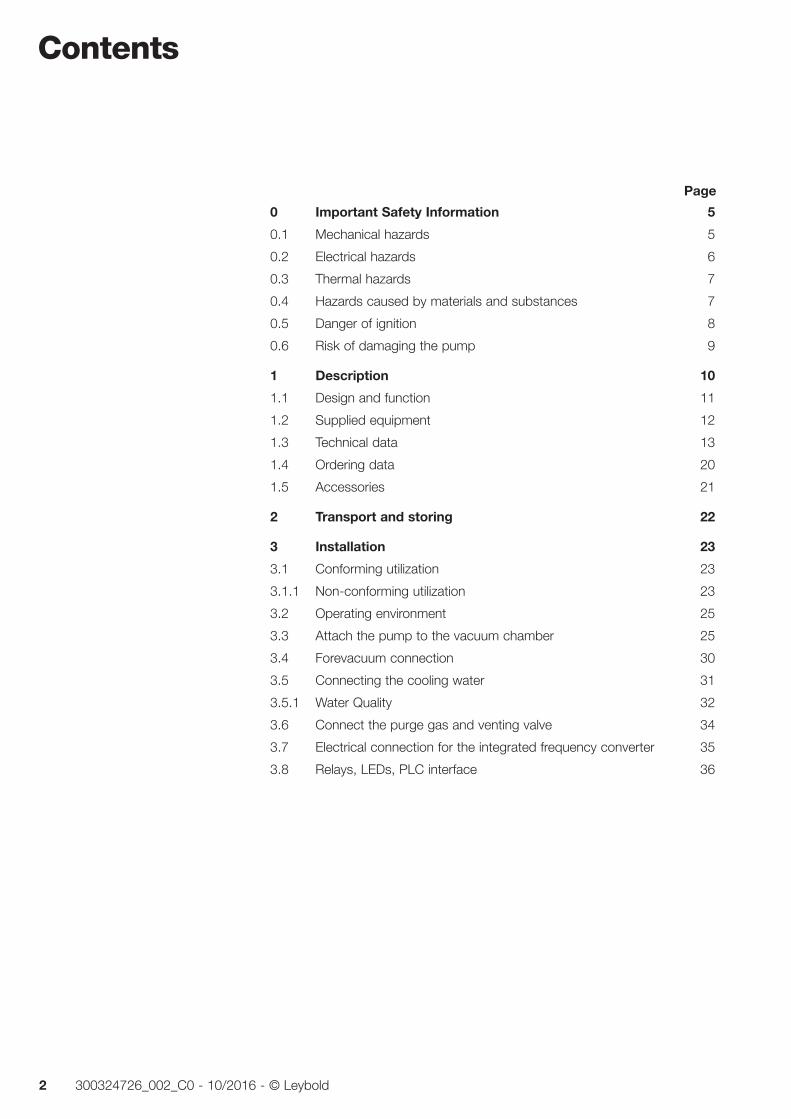
MAG integraTurbomolecular Pumps with Magnetic Bearing and Frequency Converter
Installation & Operating Instructions 300324726_002_C0
Part Nos.
411300Vxxxx
411600Vxxxx
411700Vxxxx
412200Vxxxx
and pumps modified by Leybold
Contents
2 300324726_002_C0 - 10/2016 - © Leybold
Page
0 Important Safety Information 5
0.1 Mechanical hazards 5
0.2 Electrical hazards 6
0.3 Thermal hazards 7
0.4 Hazards caused by materials and substances 7
0.5 Danger of ignition 8
0.6 Risk of damaging the pump 9
1 Description 10
1.1 Design and function 11
1.2 Supplied equipment 12
1.3 Technical data 13
1.4 Ordering data 20
1.5 Accessories 21
2 Transport and storing 22
3 Installation 23
3.1 Conforming utilization 23
3.1.1 Non-conforming utilization 23
3.2 Operating environment 25
3.3 Attach the pump to the vacuum chamber 25
3.4 Forevacuum connection 30
3.5 Connecting the cooling water 31
3.5.1 Water Quality 32
3.6 Connect the purge gas and venting valve 34
3.7 Electrical connection for the integrated frequency converter 35
3.8 Relays, LEDs, PLC interface 36
Contents
3300324726_002_C0 - 10/2016 - © Leybold
Original installation and operating instructions.
4 Operation 38
4.1 Media compatibility / purge gas 38
4.2 Interfaces 38
4.3 Switching on 39
4.4 Operation 39
4.5 Switching off 40
4.6 Venting 41
4.7 Removing the pump from the system 42
5 Maintenance 43
5.1 Cleaning 43
5.2 Changing the touch-down bearings 44
5.3 Leybold Service 44
6 Troubleshooting 45
7 Waste Disposal 46
EC Incorporation Declaration 47
EC Declaration of Conformity 48
Certificates 49
Page
Safety Information
4 300324726_002_C0 - 10/2016 - © Leybold
Obligation to Provide Information Before installing and commissioning the pump, carefully read these Operating Instructions and follow the information so as to ensure optimum and safe working right from the start.
The Leybold MAG integra has been designed for safe and efficient opera-tion when used properly and in accordance with these Operating Instructions. It is the responsibility of the user to carefully read and strictly observe all safe-ty precautions described in this section and throughout the Operating Instructions. The pump must only be operated in the proper condition and under the conditions described in the Operating Instructions. It must be oper-ated and maintained by trained personnel only. Consult local, state, and national agencies regarding specific requirements and regulations. Address any further safety, operation and/or maintenance questions to our nearest office.
DANGER indicates an imminently hazardous situation which, if not avoid-ed, will result in death or serious injury.
WARNING indicates a potentially hazardous situation which, if not avoided, could result in death or serious injury.
CAUTION indicates a potentially hazardous situation which, if not avoided, could result in minor or moderate injury.
NOTICE is used to notify users of installation, operation, programming or maintenance information that is important, but not hazard related.
We reserve the right to alter the design or any data given in these Operating Instructions. The illustrations are not binding.
Retain the Operating Instructions for further use.
NOTICE
DANGER
WARNING
CAUTION
NOTICE
Safety Information
5300324726_002_C0 - 10/2016 - © Leybold
0 Important Safety Information
0.1 Mechanical hazards1 Avoid exposing any part of the human body to the vacuum.
2 The pressure in the pump must not exceed 1.4 bar (absolute).
3 The pump is intended for generating a vacuum only. If there is a risk of an overpressure within the system and the pump, then the pump must be protected against this, by way of an overpressure safety valve, for example.
4 Vent the pump only up to atmospheric pressure.
5 When using the pump with a purge gas valve, protect the purge gas supply such that in the event of a malfunction no overpressure can occur within the system.
6 The pump must be firmly mounted to the vacuum chamber. If the mounting is not sturdy enough, pump blockage could cause the pump to break loose; internal pump components could be thrown in all directions. Never operate the pump (in bench testing, for example) without proper flanging to the vacuum chamber. Observe the informa-tion in Section 3.3.
7 We recommend to change the rotor after 80,000 hours of operation or 20,000 cycles at the latest. Due to high-speed and temperature, the service life of the rotor is limited. If the rotor is changed too late, it may be destroyed. Thus in the flange mounts high forces and torque condi-tions can occur. The mounting screws for the pump may be torn off. When using clamped flange connections at the housing or with com-ponents above the housing, sudden twisting of the entire pump can be experienced.
8 Turbopumps as described in the following operation manual contain a high portion of kinetic energy due to their high rotational speed in combination with the specific rotor mass. In case of a malfunction of the system, for example rotor/stator contact or even a rotor crash, the rotational energy is released.
9 To avoid the destruction of the equipment and to prevent injuries of the operating staff the leading European manufacturers of vacuum pumps strictly recommend to follow the installation instructions as given in this manual.
WARNING
Safety Information
6 300324726_002_C0 - 10/2016 - © Leybold
0.2 Electrical hazards1 The electrical connection must only be provided by a trained person.
Please observe the national regulations in the country of use like EN 50110-1 for Europe, for example.
2 Lethal voltages are present at the mains connections. Before starting with any maintenance and service work, de-energise (lockout/tagout) the product first.
3 Unplug any connectors only when the mains voltage is switched off and the pump does no longer turn
4 At speeds approximately below 200 Hz, there will not be enough power any more for the LEDs, i.e. the pump may still turn with out any of the LEDs being on.
5 Unauthorized device conversion and modifications are prohibited for safety reasons.
6 Hazardous voltages are present within the frequency converter. When coming into contact with these, death or severe injury can result. After the pump has arrived at standstill, disconnect the frequency converter from the mains power and prevent it against being switched on inad-vertently (lockout/tagout) before opening it. Basically there is no reason why the frequency converter should be opened. There are no user ser-viceable parts inside.
Should, even so, changes be made to the pump-frequency converter system then a trained electrician, as specified by the standard EN 50110-1, for example, must perform an electrical safety test again in accordance with the locally applicable safety regulations.
7 Lay connecting lines so that they cannot be damaged. Protect the lines against humidity and contact with water. Avoid any heat stress on the line due to unfavourable laying conditions.
8 Suitably support the connecting lines so that the pumps are not exposed to any major mechanical stress.
9 Do not expose pump, frequency converter and the connections to dripping water. Note the information on the IP type of protection.
10 When storing pump, frequency converter and connecting lines in a humid atmosphere, these can suffer corrosion. Corrosion gives rise to conductive deposits which in turn can cause short-circuits and reduce the insulation levels of electrical components
11 Transport pump, frequency converter and connecting cables only in their original packaging so as to avoid any mechanical damage which in turn may reduce air gaps and creepage distances.
12 When applying external voltages above 42 V to the connection termi-nals, observe the applicable VDE safety regulations!
13 Make the electrical connections only after pump and accessories (e.g. air cooler) have been installed mechanically
WARNING
Safety Information
7300324726_002_C0 - 10/2016 - © Leybold
0.3 Thermal hazards1 Handle the equipment only while vented and cooled down.
2 During operation of the pump certain areas can get so hot (80 °C max.) so that there is the risk of suffering burns. Protect hot parts against being touched.
3 Note the warning information on the housing surface. If these warning notices have been removed, covered or obstructed, include corre-sponding additional warning notices.
0.4 Hazards caused by materials and substances1 The pump is not suited for pumping of reactive, corrosive or toxic
media. If the rotor is attacked by process gases, it can suffer destruc-tion. Thus in the flange mounts high forces and torque conditions can occur. The mounting screws for the pump may be torn off. When using clamped flange connections at the housing or with components above the housing, sudden twisting of the entire pump can be experi-enced.
2 The operator of the system must ensure that no plasma is to enter the pump. Otherwise it may lead to a failure of the pump.
3 When pumping dusty media, use a dust filter.
4 If low concentration corrosive or reactive gases are being pumped, then operate the pump with purge gas.
5 Please consult us as to which types of pump are required for specific processes and applications.
6 The forevacuum line must be tight. Hazardous gases can escape at leaks or the gases being pumped can react with air or humidity. A leak search will always be required after having installed the pump and after service work on the vacuum. Upon delivery the pump has an integral leak rate of < 5 · 10-7 mbar·l/s.
7 If the pump has previously handled hazardous gases, implement the proper precautionary measures before opening the intake or exhaust connection. Before opening the pump, purge it for a longer period of time with an inert gas. If necessary, use gloves, a respirator and/or protective clothing and work under an exhaust hood. Firmly seal off the pump. When shipping the contaminated pump for servicing, please also state the type of hazard. For this you must use a form which we have pre-pared for you.
8 Contaminated parts can be detrimental to health and environment. Before beginning with any work, first find out whether any parts are contaminated. Adhere to the relevant regulations and take the neces-sary precautions when handling contaminated parts.
CAUTION
DANGER
Safety Information
8 300324726_002_C0 - 10/2016 - © Leybold
0.5 Danger of ignition1 During operation the pressure inside the turbomolecular pump is so
low that there is no danger of ignition (at pressures below about 100 mbar). A hazardous condition will be created if flammable mixtures enter the hot pump at pressures above 100 mbar. During operation the pump can reach temperatures as high as 120°C internally, and at parts of the outside surfaces 80 °C. Sparks could occur in case of damage to the pump and these could ignite explosive mixtures. Also note the safety information provided by the gas supplier.
CAUTION
Safety Information
9300324726_002_C0 - 10/2016 - © Leybold
0.6 Risk of damaging the pump1 Never touch the rotor. Touching the rotor may cause injury and
damage the rotor bearing.
2 Foreign objects which enter the pump through the intake would cause serious damage to the rotor. That’s why we recommend installing an inlet screen. Damages caused during operation without the inlet screen are excluded from warranty.
3 The contact surfaces of pump housing, vacuum system and centering ring must be free of grease and dry so as to ensure sufficient stability in case the rotor seizes.
4 Connect a purge gas or venting valve to the correct flange. Confusing the forevacuum and purge gas flange can cause shock venting of the pump.
5 The interface connectors have UNC 4-40 threads. Do not use connec-tors with M3 treads.
6 Disconnect and connect the cable connections only while the pump is turning no longer (green status LED off) and with the mains power switched off (yellow power LED off). Other wise there is the risk of dam-aging the frequency converter.
7 Do not stop the MAG with the mains. Switching off the mains while the pump is running will wear out the touch down bear ings.
8 Exposure of the pump to accelerating forces must be avoided or reduced to such an extent that the rotor unit will not be excited by vibrations. In the case of critical applications you must consult our Applications Dept. first.
9 Connect the pump in an EMC compliant manner so as to avoid line related interference.
Pressures given in bar or mbar are absolute values. If exceptionally a gauge pressure is meant, a “g” is added (bar(g)).
NOTICE
Description
10 300324726_002_C0 - 10/2016 - © Leybold
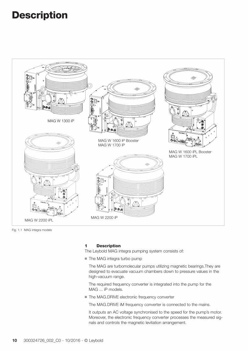
1 DescriptionThe Leybold MAG integra pumping system consists of:
The MAG integra turbo pump
The MAG are turbomolecular pumps uti li zing magnetic bearings.They are designed to evacuate va cuum chambers down to pressure values in the high-vacuum range.
The required frequency converter is integrated into the pump for the MAG ... iP models.
The MAG.DRIVE electronic frequency converter
The MAG.DRIVE iM frequency converter is connected to the mains.
It outputs an AC voltage synchronised to the speed for the pump’s motor. Moreover, the electronic frequency converter processes the measured sig-nals and controls the magnetic levitation arrangement.
Fig. 1.1 MAG integra models
MAG W 1300 iP
MAG W 1600 iP
MAG W 2000 iP
MAG W 1600 iPL BoosterMAG W 1700 iPL
MAG W 1600 iP BoosterMAG W 1700 iP
MAG W 2200 iPLMAG W 2200 iP
Description
11300324726_002_C0 - 10/2016 - © Leybold
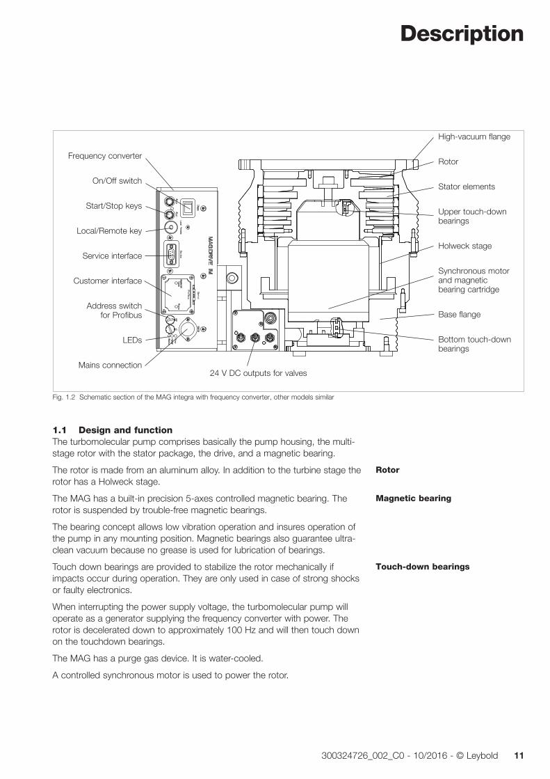
1.1 Design and functionThe turbomolecular pump comprises basically the pump housing, the multi-stage rotor with the stator package, the drive, and a magnetic bearing.
The rotor is made from an aluminum alloy. In addition to the turbine stage the rotor has a Holweck stage.
The MAG has a built-in precision 5-axes controlled magnetic bearing. The rotor is suspended by trouble-free magnetic bearings.
The bearing concept allows low vibration operation and insures operation of the pump in any mounting position. Magnetic bearings also guarantee ultra-clean vacuum because no grease is used for lubrication of bearings.
Touch down bearings are provided to stabilize the rotor mechanically if impacts occur during operation. They are only used in case of strong shocks or faulty electronics.
When interrupting the power supply voltage, the turbomolecular pump will operate as a generator supplying the frequency converter with power. The rotor is decelerated down to approximately 100 Hz and will then touch down on the touchdown bearings.
The MAG has a purge gas device. It is water-cooled.
A controlled synchronous motor is used to power the rotor.
Rotor
Magnetic bearing
Touch-down bearings
High-vacuum flange
Rotor
Stator elements
Upper touch-down bearings
Holweck stage
Synchronous motor and magnetic bearing cartridge
Base flange
Bottom touch-down bearings
Fig. 1.2 Schematic section of the MAG integra with frequency converter, other models similar
Frequency converter
On/Off switch
Start/Stop keys
Local/Remote key
Service interface
Customer interface
Address switch for Profibus
LEDs
Mains connection24 V DC outputs for valves
Description
12 300324726_002_C0 - 10/2016 - © Leybold
Drive voltage for the motor and the operating voltage for the magnetic bear-ing are supplied by the MAG.DRIVE iM frequency converter. It also handles the automatic monitoring of these systems.
The converter monitors continously all important operating parameters and provides warning and alarm signals in case the operating conditions exceed the specification or the set threshold.
Switching the motor to the generator mode keeps the magnetic bearing unit in operation even in case of a mains power failure.
The frequency converter has the following interfaces:
a Profibus or another optional interface, see Section 4.2
an interface for the Leybold Service (RS 232) and
three connections for accessories, e.g. valves.
1.2 Supplied equipmentThe pumps are shipped sealed in a PE bag with a desiccant to absorb mois-ture.The maximum useful life of the desiccant is one year.
The forevacuum flange is capped with a protective cap. The purge gas and venting flange is blank-flanged with centering ring with FPM sealing ring and a clamping yoke.
The high-vacuum connection elements are not part of the standard equipment. An inlet screen has been built in.
A mains mating connector for the frequency converter side (IP 54) is sup-plied. A cable and a mains plug are not part of the standard equipment.
———————————————PE = PolyethyleneFPM = Fluororubber, resistant to temperatures up to 150°C (302 °F)
Frequency converter
Description
13300324726_002_C0 - 10/2016 - © Leybold
1.3 Technical data
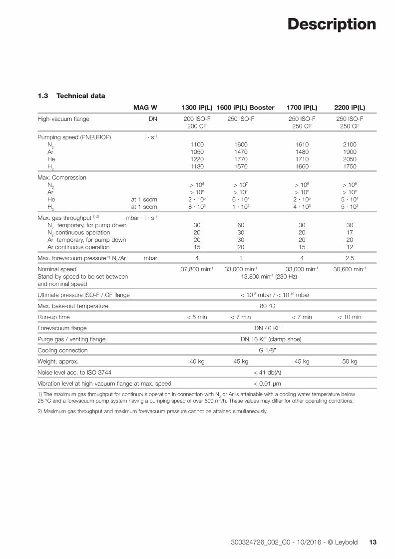
MAG W 1300 iP(L) 1600 iP(L) Booster 1700 iP(L) 2200 iP(L)
High-vacuum flange DN 200 ISO-F 250 ISO-F 250 ISO-F 250 ISO-F 200 CF 250 CF 250 CF
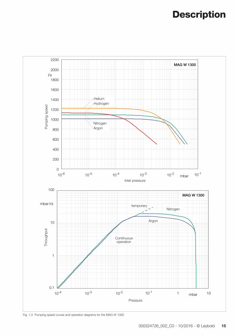
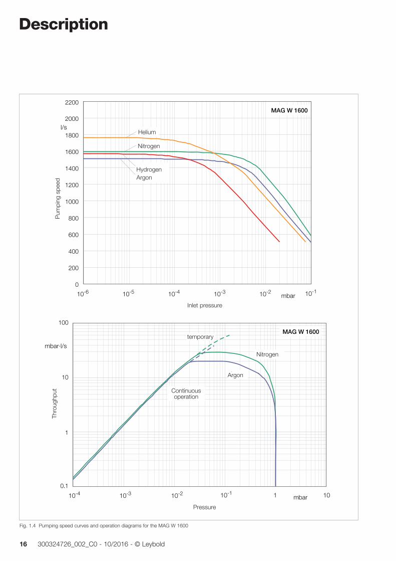
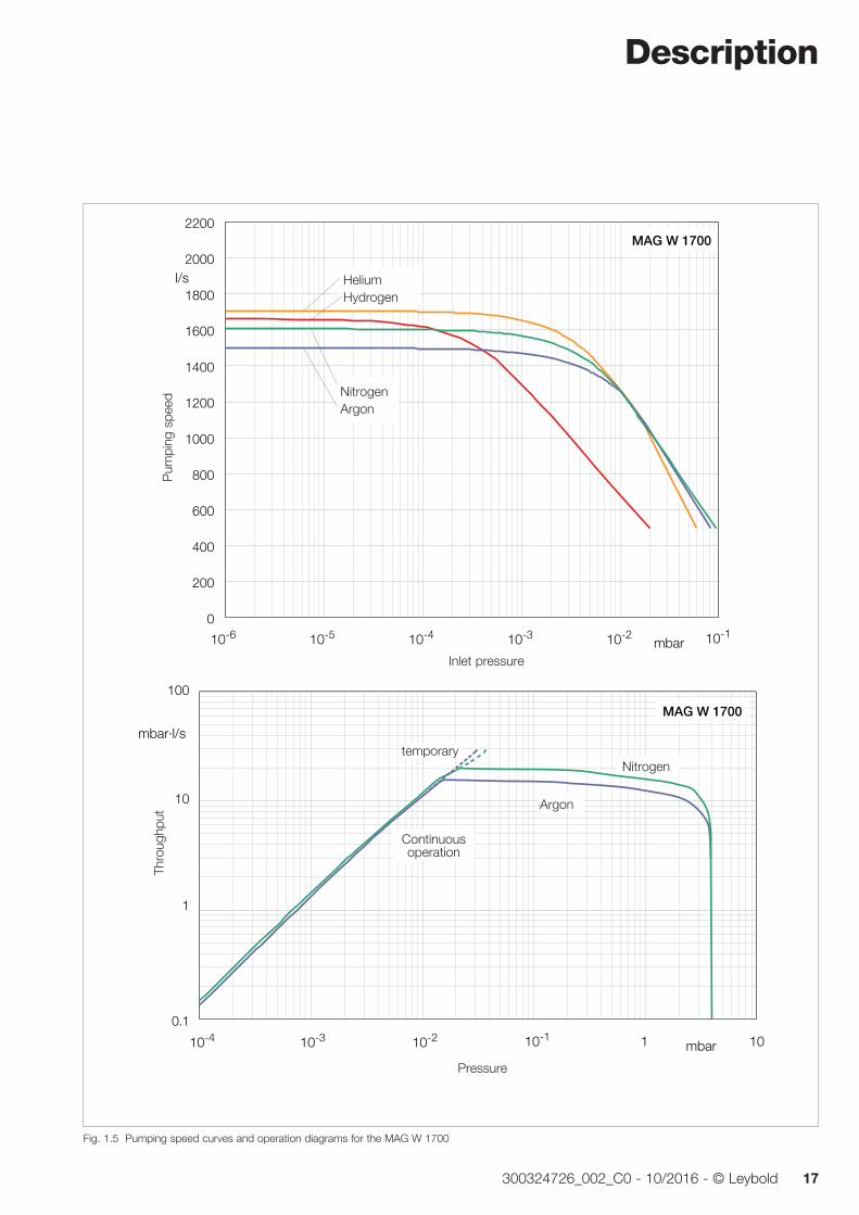
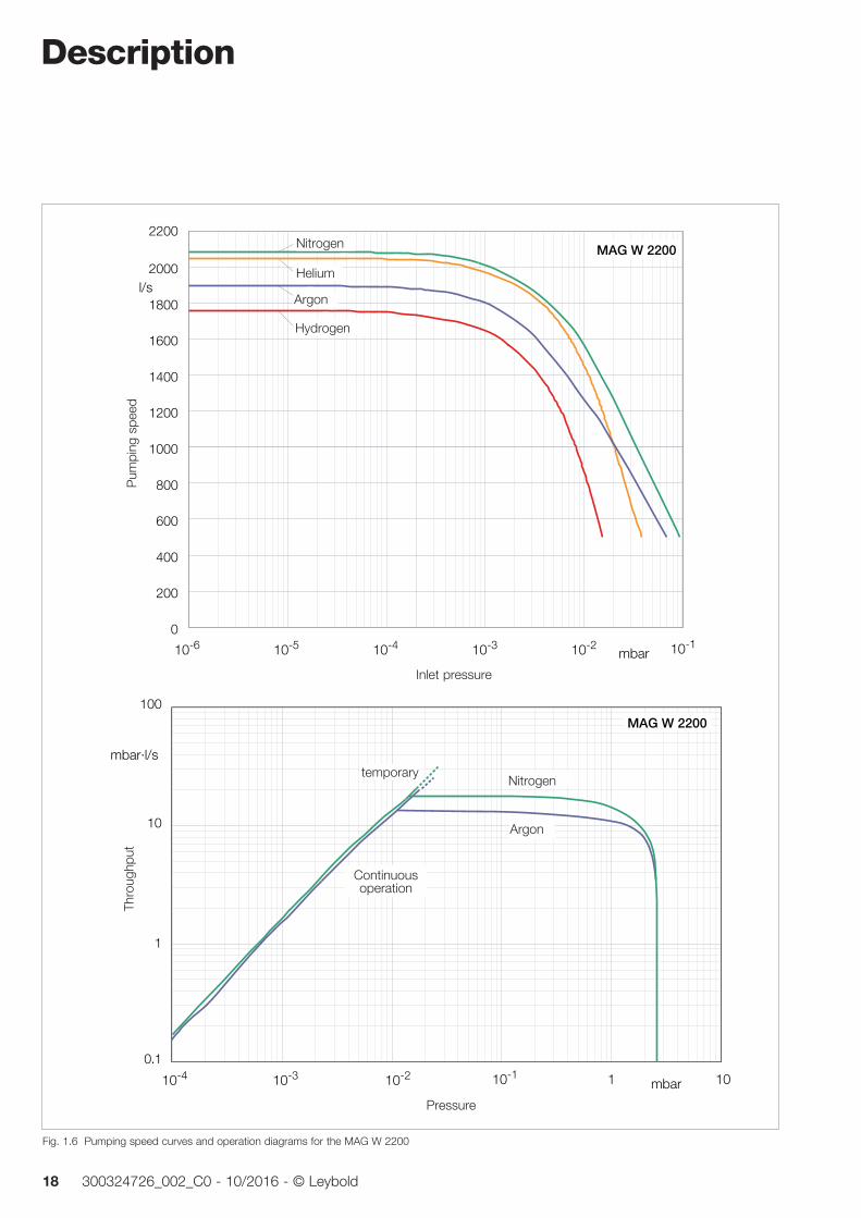
Pumping speed (PNEUROP) I · s-1 N2 1100 1600 1610 2100 Ar 1050 1470 1480 1900 He 1220 1770 1710 2050 H2 1130 1570 1660 1750
Max. Compression N2 > 108 > 107 > 108 > 108 Ar > 108 > 107 > 108 > 108 He at 1 sccm 2 · 105 6 · 104 2 · 105 5 · 104 H2 at 1 sccm 8 · 103 1 · 103 4 · 103 5 · 103
Max. gas throughput 1) 2) mbar · I · s-1
N2 temporary, for pump down 30 60 30 30 N2 continuous operation 20 30 20 17 Ar temporary, for pump down 20 30 20 20 Ar continuous operation 15 20 15 12
Max. forevacuum pressure 2) N2/Ar mbar 4 1 4 2.5
Nominal speed 37,800 min-1 33,000 min-1 33,000 min-1 30,600 min-1
Stand-by speed to be set between 13,800 min-1 (230 Hz) and nominal speed
Ultimate pressure ISO-F / CF flange < 10-8 mbar / < 10-10 mbar
Max. bake-out temperature 80 °C
Run-up time < 5 min < 7 min < 7 min < 10 min
Forevacuum flange DN 40 KF
Purge gas / venting flange DN 16 KF (clamp shoe)
Cooling connection G 1/8”
Weight, approx. 40 kg 45 kg 45 kg 50 kg
Noise level acc. to ISO 3744 < 41 db(A)
Vibration level at high-vacuum flange at max. speed < 0.01 µm
1) The maximum gas throughput for continuous operation in connection with N2 or Ar is attainable with a cooling water temperature below 25 °C and a forevacuum pump system having a pumping speed of over 600 m3/h. These values may differ for other operating conditions.
2) Maximum gas throughput and maximum forevacuum pressure cannot be attained simultaneously.
Description
14 300324726_002_C0 - 10/2016 - © Leybold
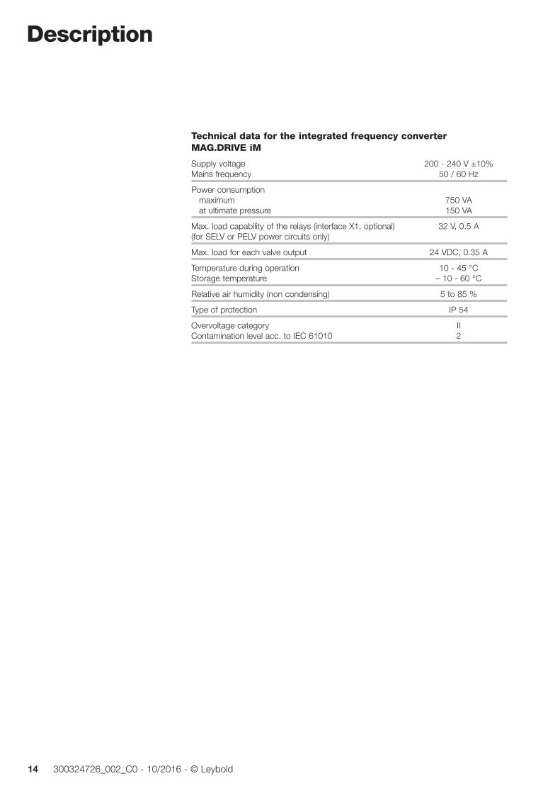
Technical data for the integrated frequency converter MAG.DRIVE iM
Supply voltage 200 - 240 V ±10% Mains frequency 50 / 60 Hz
Power consumption maximum 750 VA at ultimate pressure 150 VA
Max. load capability of the relays (interface X1, optional) 32 V, 0.5 A (for SELV or PELV power circuits only)
Max. load for each valve output 24 VDC, 0.35 A
Temperature during operation 10 - 45 °C Storage temperature – 10 - 60 °C
Relative air humidity (non condensing) 5 to 85 %
Type of protection IP 54
Overvoltage category II Contamination level acc. to IEC 61010 2
Description
15300324726_002_C0 - 10/2016 - © Leybold
mbar10-210-310-4 10-1
Vorvakuumdruck
101
100
1
10
0.1
mbar·l/s
Dur
chflu
ss
Stickstoff
MAG W 1300
Argon
0
200
400
600
800
1000
1200
1400
1600
1800
2000l/s
Sau
gver
mög
en
mbar10-210-310-410-510-6 10-1
Hochvakuumdruck
MAG W 1300
ArgonStickstoff
HeliumWasserstoff
2200
Fig. 1.3 Pumping speed curves and operation diagrams for the MAG W 1300
temporary
Continuous operation
Nitrogen
Thro
ughp
ut
Pressure
NitrogenArgon
Argon
HeliumHydrogen
Inlet pressure
Pum
ping
spe
ed
Description
16 300324726_002_C0 - 10/2016 - © Leybold
0
200
400
600
800
1000
1200
1400
1600
1800
2000l/s
Sau
gver
mög
en
mbar10-210-310-410-510-6 10-1
Hochvakuumdruck
MAG W 1600
Helium
Argon
Stickstoff
Wasserstoff
2200
mbar10-210-310-4 10-1
Vorvakuumdruck
101
100
1
10
0.1
mbar·l/s
Dur
chflu
ss
Stickstoff
MAG W 1600
Argon
Fig. 1.4 Pumping speed curves and operation diagrams for the MAG W 1600
temporary
Continuous operation
Nitrogen
Thro
ughp
ut
Pressure
HydrogenArgon
Argon
Helium
Inlet pressure
Pum
ping
spe
ed
Nitrogen
Description
17300324726_002_C0 - 10/2016 - © Leybold
0
200
400
600
800
1000
1200
1400
1600
1800
2000l/s
Sau
gver
mög
en
mbar10-210-310-410-510-6 10-1
Hochvakuumdruck
MAG W 1700
HeliumWasserstoff
Argon
Stickstoff
mbar10-210-310-4 10-1
Vorvakuumdruck
101
100
1
10
0.1
mbar·l/s
Dur
chflu
ss
Stickstoff
Argon
MAG W 1700
2200
Fig. 1.5 Pumping speed curves and operation diagrams for the MAG W 1700
temporary
Continuous operation
Nitrogen
Thro
ughp
ut
Pressure
NitrogenArgon
Argon
HeliumHydrogen
Inlet pressure
Pum
ping
spe
ed
Description
18 300324726_002_C0 - 10/2016 - © Leybold
mbar10-210-310-4 10-1
Druck
101
100
1
10
0.1
mbar·l/s
Dur
chflu
ss
0
1000
2000l/s
Sau
gver
mög
en
mbar10-210-310-410-510-6 10-1
Hochvakuumdruck
MAG W 2200
Wasserstoff
Stickstoff
Helium
Stickstoff
MAG W 2200
Argon
200
400
600
800
1200
1400
1600
1800
2200
Argon
Fig. 1.6 Pumping speed curves and operation diagrams for the MAG W 2200
temporary
Continuous operation
Nitrogen
Thro
ughp
ut
Pressure
Nitrogen
Argon
Helium
Inlet pressure
Pum
ping
spe
ed
Argon
Hydrogen
Description
19300324726_002_C0 - 10/2016 - © Leybold
Ø d1
h
94
114
b
17° 17°
260
98Ø d2
s2
s1
s3
7
I
Vorvakuum Sperrgas
Ø d1
hh 1
DN
251
114
iP iPL
l1
l2
s4
s 5
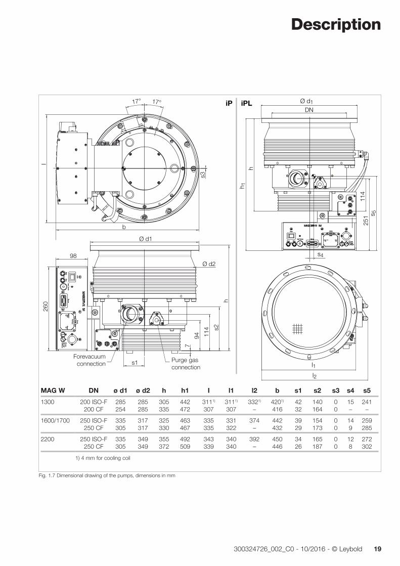
DN ø d1 ø d2 h h1 I l1 l2 b s1 s2 s3 s4 s5
200 ISO-F 285 285 305 442 3111) 3111) 3321) 4201) 42 140 0 15 241 200 CF 254 285 335 472 307 307 – 416 32 164 0 – –
250 ISO-F 335 317 325 463 335 331 374 442 39 154 0 14 259 250 CF 305 317 330 467 335 322 – 432 29 173 0 9 285
250 ISO-F 335 349 355 492 343 340 392 450 34 165 0 12 272 250 CF 305 349 372 509 339 340 – 446 26 187 0 8 302
1) 4 mm for cooling coil
Fig. 1.7 Dimensional drawing of the pumps, dimensions in mm
MAG W
1300
1600/1700
2200
Forevacuum connection
Purge gas connection
Description
20 300324726_002_C0 - 10/2016 - © Leybold
1.4 Ordering data
Part No.
Pump with integrated converter and purge gas port, Type of protection IP 54* with Profibus 24 V PLC Interface
MAG W 1300 iP DN 200 ISO-F 411300V0504 411300V0514 MAG W 1300 iP DN 200 CF 411300V0506 411300V0516 MAG W 1300 iPL DN 200 ISO-F 411300V0704 411300V0714 MAG W 1300 iPL DN 200 CF 411300V0706 411300V0716
MAG W 1600 iP Booster DN 250 ISO-F 411600V0504 411600V0514 MAG W 1600 iPL Booster DN 250 ISO-F 411600V0704 411600V0714
MAG W 1700 iP DN 250 ISO-F 411700V0504 411700V0514 MAG W 1700 iP DN 250 CF 411700V0506 411700V0516 MAG W 1700 iPL DN 250 ISO-F 411700V0704 411700V0714 MAG W 1700 iPL DN 250 CF 411700V0706 411700V0716
MAG W 2200 iP DN 250 ISO-F 412200V0504 412200V0514 MAG W 2200 iP DN 250 CF 412200V0506 412200V0516 MAG W 2200 iPL DN 250 ISO-F 412200V0704 412200V0714 MAG W 2200 iPL DN 250 CF 412200V0706 412200V0716
other interfaces on request
* The IP 54 type of protection is only ensured with an IP 54 protection cap on the customer interface. Pump versions without IP 54 protection cap can only be classified as IP 20. Please consult with us for an optional IP 54 protection cap.
Description
21300324726_002_C0 - 10/2016 - © Leybold
1.5 Accessories
Required accessories
Set of bolts, nuts and washers for ISO-F flange (12 each) 400153V0012 Bolts M 10 x 50 Bolts M 10 x 35 400153V0010 Bolt quality 12.9 acc. to EN ISO 898-1 with coating; 0,2 % yield strength > 1080 N/mm2
Centering ring with O-ring DN 200 DN 250 Al/FPM 268 44 268 45 Stainless steel/FPM 887 02 887 08
Set of bolts, nuts and washers for CF flange (8 each) 400153V0016 Bolts M 8 x 40 Bolt quality 10.9 acc. to EN ISO 898-1 with coating; 0,2 % yield strength > 900 N/mm2 (for DN 200 3 sets required, for DN 250 4 sets)
Copper gasket rings for CF flange DN 200 (Set of 10 pieces) 839 47 DN 250 (Set of 5 pieces) 839 48
Set of hex. screws with nuts, screws and washers for CF flange DN 200 839 07 DN 250 (2 sets required) 839 07
Optional accessories
Mains cable for MAG.DRIVE iM, 2.5 m EU 411310V03 US 411320V03
Inlet screen DN 200 ISO-F and DN 200 CF E 200 04 558 DN 250 ISO-F and DN 250 CF E 200 04 557
Seal Kit DN 250 Metal 200 07 901
Seal Kit Metal for other flanges on request
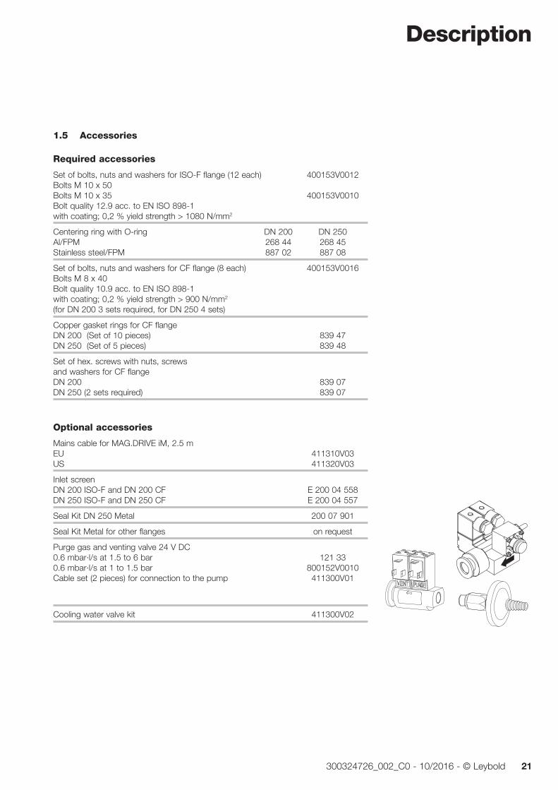
Purge gas and venting valve 24 V DC 0.6 mbar·l/s at 1.5 to 6 bar 121 33 0.6 mbar·l/s at 1 to 1.5 bar 800152V0010 Cable set (2 pieces) for connection to the pump 411300V01
Cooling water valve kit 411300V02
800152V0013 800110V0012800110V0011
Transport and storing
22 300324726_002_C0 - 10/2016 - © Leybold
2 Transport and storingRemove the equipment from the transportation box and keep the packaging. Make sure that the product has not been damaged during transportation. If this unit is damaged contact your carrier and inform Leybold if necessary.
To prevent damages to the pump, use the packaging pro vided for storage and transport.
Be careful not to damage the sockets and connections during transporta-tion.
Do not stand below the pump while connecting or removing the turbo-molecular pump.
The turbomolecular pump is shipped in a sealed PE bag with desiccant. Do not open the sealed package until immediately before installing.
Do not remove the covers and blanking flanges until you are ready to make the connections, to ensure that the turbomolecular pump is installed under the cleanest possible conditions.
Turbomolecular pumps which were not operated for a period of over 12 months should be returned to us. For more information on this please con-tact your local sales partner.
Do not store pump and accessories in a moist atmosphere so as to prevent these items from suffering corrosion.
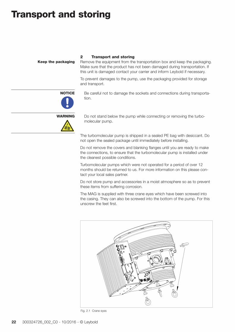
The MAG is supplied with three crane eyes which have been screwed into the casing. They can also be screwed into the bottom of the pump. For this unscrew the feet first.
Keep the packaging
NOTICE
WARNING
Fig. 2.1 Crane eyes
Installation
23300324726_002_C0 - 10/2016 - © Leybold
3 Installation
3.1 Conforming utilizationThe turbomolecular pump is intended for generating a vacuum. It is suited for non-corrosive processes only.
The turbomolecular pump must be bolted to a rigid vacuum system and con-nected to a suitable backing pump.
The turbomolecular pump must only be operated with correspondingly speci-fied frequency converters, the special connecting cables and mounting bolts.
Both pump and frequency converter are intended for being operated within closed rooms.
The use of any accessories which have not been specified by Leybold is only allowed after approval by Leybold.
The supplied integrated MAG.DRIVE iM frequency converter will be required for the operation of the turbomolecular pump.
3.1.1 Non-conforming utilizationNon-conforming utilizations for both pump and frequency converter are among others:
Pumping of gases and vapours for which the materials of the pump are unsuitable.
Pumping of toxic gases
Operation in connection with processes in which GaAs (gallium arsenide) is being pumped.
Pumping of gas mixtures with an oxygen content of > 21%.
Pumping of corrosive gases
Pumping of dust containing gases without purge gas operation.
Pumping of condensable vapours without suitably controlling the tempera-ture of the pump. Upon compression within the pump, these vapours may condense or form deposits.
Pumping of dusts and solids without the use of suitable screens and filters.
Operation at an inadmissibly high forevacuum pressure.
Operation at inadmissibily high gas loads.
Utilization of both pump and frequency converter in explosion hazard areas.
Non-compliance of the specified maintenance and servicing intervals for both pump and frequency converter.
Operation of the pump and drive electronics in environments which demand protection type IP 54 or higher and where the installation site is over 1000 m the above sea level.
Installation
24 300324726_002_C0 - 10/2016 - © Leybold
Utilization in systems and pump systems in which the pressure may exceed 1.4 bar abs.
Operation with an inadequately mounted pump.
Operation without having flanged the pump to the system or without hav-ing connected it to a suitable backing pump.
Operation with additional heat sources involving thermal radiation, thermal conduction via the high vacuum or the forevacuum flange, strong magnetic fields or very hot process gases, for example.
Use in systems in which impact stress and vibrations or periodically occur-ring forces affect pump, frequency converter and cables.
Operation on moving system or system components (locks or movable pump systems, for example).
Operation at vibration absorbers and vacuum components (gate valves, valves) which are not capable of sustaining the specified deceleration torque should the pump rotor seize.
Stepping on pump, add-on parts, drive electronics, flanges and cables to climb onto the system.
Fitting of add-on parts to the forevacuum flange which cause an inadmissi-ble high load.
Removing, covering or obstructing warning notices.
Standstill or storing of pump and drive electronics without suitable seal ing-off and drying. Storing in a humid atmosphere can cause corrosion.
Conversions, manipulations and maintenance work by personnel not authorised by Leybold.
Any non-conforming utilisation of pump, frequency converter and accesso-ries can result in severe injury and cause damage to components.
WARNING
Installation
25300324726_002_C0 - 10/2016 - © Leybold
3.2 Operating environmentThe maximum permissible ambient temperature is 45 °C (113 °F). Do not expose the pump or the frequency converter with type of protection IP 30 to dripping or spraying water.
If the pump is used within a magnetic field, the magnetic induction at the surface of the pump housing may not exceed: B = 5 mT if impinging radially and B = 15 mT if impinging axially.
Exceeding this limit can cause excessive rotor hea ting due to the eddy cur-rents generated in this situation. It is therefore necessary to provide suitable shielding in such cases.
Places of installation up to 1000 m above sea level (3300 ft) are possible without restrictions. At altitudes over 1000 m heat dissipation by the ambient air is impaired. Please consult us.
The frequency converter must not be operated in explosive gas atmo spheres.
3.3 Attach the pump to the vacuum chamber
Never touch the rotor. Touching the rotor may cause injury and damage the rotor bearing.
The high-vacuum flange must be solidly mounted to the vacuum chamber. Observe Safety Information 0.1.6.
The shipping flange and bolts may be used only for shipping purposes; they are not suitable for mounting the pumps in systems.
Remove the transport seal from the intake flange and remove the desiccant. Pay attention to maximum cleanliness when connecting.
In the case of a sudden rotor vane rupture or rotor-stator contact which may occur in practice (caused, for example, by solid objects from the process chamber entering the pump through the high vacuum flange), a crash momentum amounting to 5 kNm maximum needs to be absorbed by the system.
When not complying with the installation and operating conditions or the maintenance intervals described in the Operating Instructions, the rotor may suffer complete destruction by material fatigue, for example. In this case which is highly unlikely to occur in practice, a deceleration or burst momen-tum of 35 kNm maximum needs to be absorbed by the system, should the pump suddenly seize.
We have successfully tested the pumps in agreement with ISO 27892 both against crashes and also bursts.
Ambient temperature
Magnetic field
Places of installation
NOTICE
WARNING
Torques when the rotor seizes
Installation
26 300324726_002_C0 - 10/2016 - © Leybold
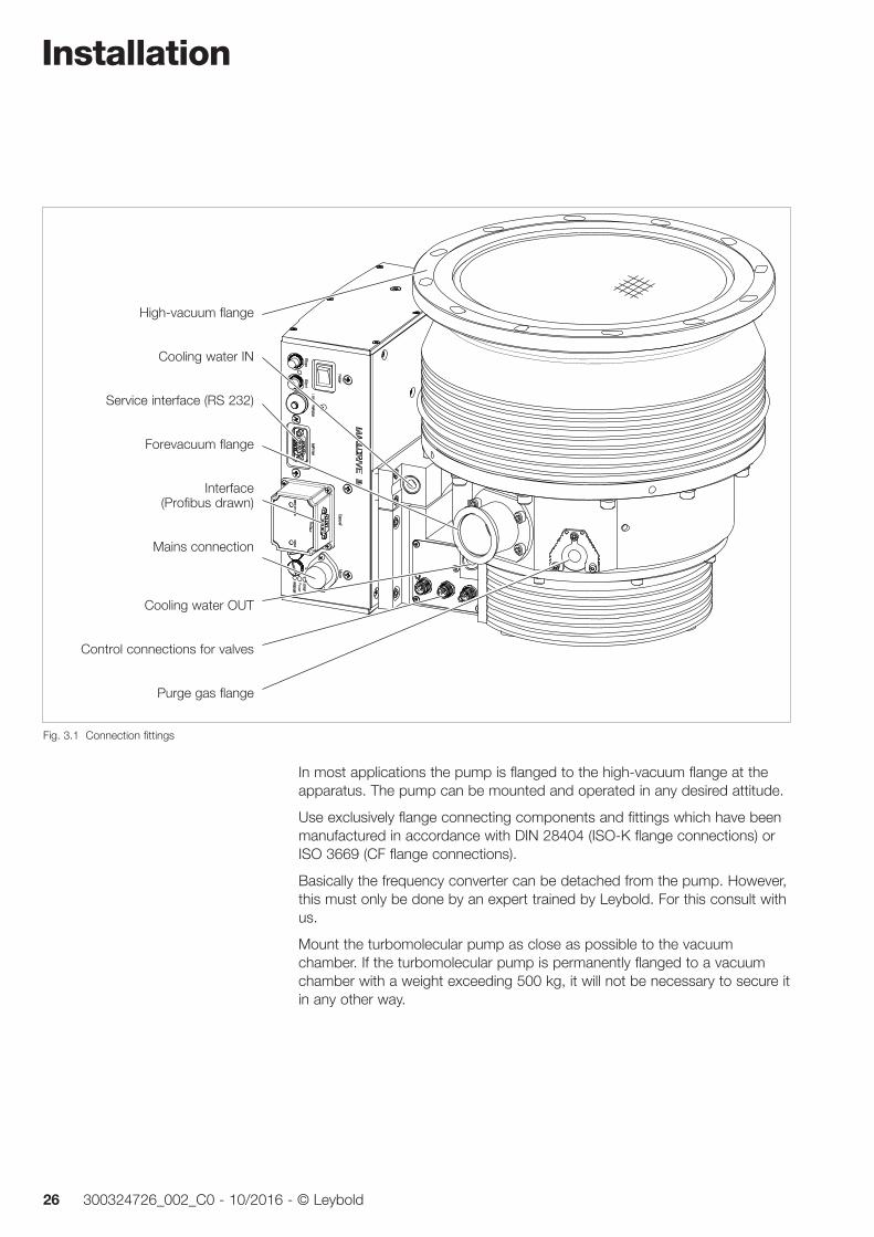
In most applications the pump is flanged to the high-vacuum flange at the apparatus. The pump can be mounted and operated in any desired attitude.
Use exclusively flange connecting components and fittings which have been manufactured in accordance with DIN 28404 (ISO-K flange connections) or ISO 3669 (CF flange connections).
Basically the frequency converter can be detached from the pump. However, this must only be done by an expert trained by Leybold. For this consult with us.
Mount the turbomolecular pump as close as possible to the vacuum chamber. If the turbomolecular pump is permanently flanged to a vacuum chamber with a weight exceeding 500 kg, it will not be necessary to secure it in any other way.
High-vacuum flange
Cooling water IN
Service interface (RS 232)
Forevacuum flange
Interface (Profibus drawn)
Mains connection
Cooling water OUT
Control connections for valves
Purge gas flange
Fig. 3.1 Connection fittings
Installation
27300324726_002_C0 - 10/2016 - © Leybold
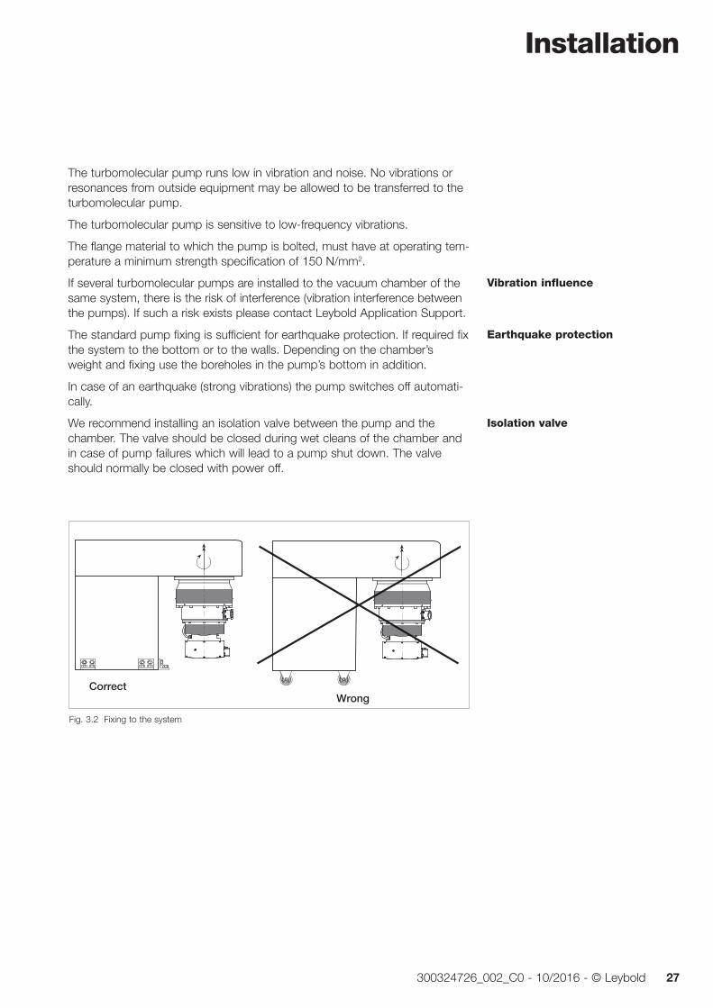
The turbomolecular pump runs low in vibration and noise. No vibrations or resonances from outside equipment may be allowed to be transferred to the turbomolecular pump.
The turbomolecular pump is sensitive to low-frequency vibrations.
The flange material to which the pump is bolted, must have at operating tem-perature a minimum strength specification of 150 N/mm2.
If several turbomolecular pumps are installed to the vacuum chamber of the same system, there is the risk of interference (vibration interference between the pumps). If such a risk exists please contact Leybold Application Support.
The standard pump fixing is sufficient for earthquake protection. If required fix the system to the bottom or to the walls. Depending on the chamber’s weight and fixing use the boreholes in the pump’s bottom in addition.
In case of an earthquake (strong vibrations) the pump switches off automati-cally.
We recommend installing an isolation valve between the pump and the chamber. The valve should be closed during wet cleans of the chamber and in case of pump failures which will lead to a pump shut down. The valve should normally be closed with power off.
Vibration influence
Earthquake protection
Isolation valve
RichtigFalsch
Fig. 3.2 Fixing to the system
CorrectWrong
Installation
28 300324726_002_C0 - 10/2016 - © Leybold
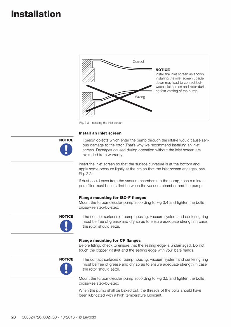
Install an inlet screen
Foreign objects which enter the pump through the intake would cause seri-ous damage to the rotor. That’s why we recommend installing an inlet screen. Damages caused during operation without the inlet screen are excluded from warranty.
Insert the inlet screen so that the surface curvature is at the bottom and apply some pressure lightly at the rim so that the inlet screen engages, see Fig. 3.3.
If dust could pass from the vacuum chamber into the pump, then a micro-pore filter must be installed between the vacuum chamber and the pump.
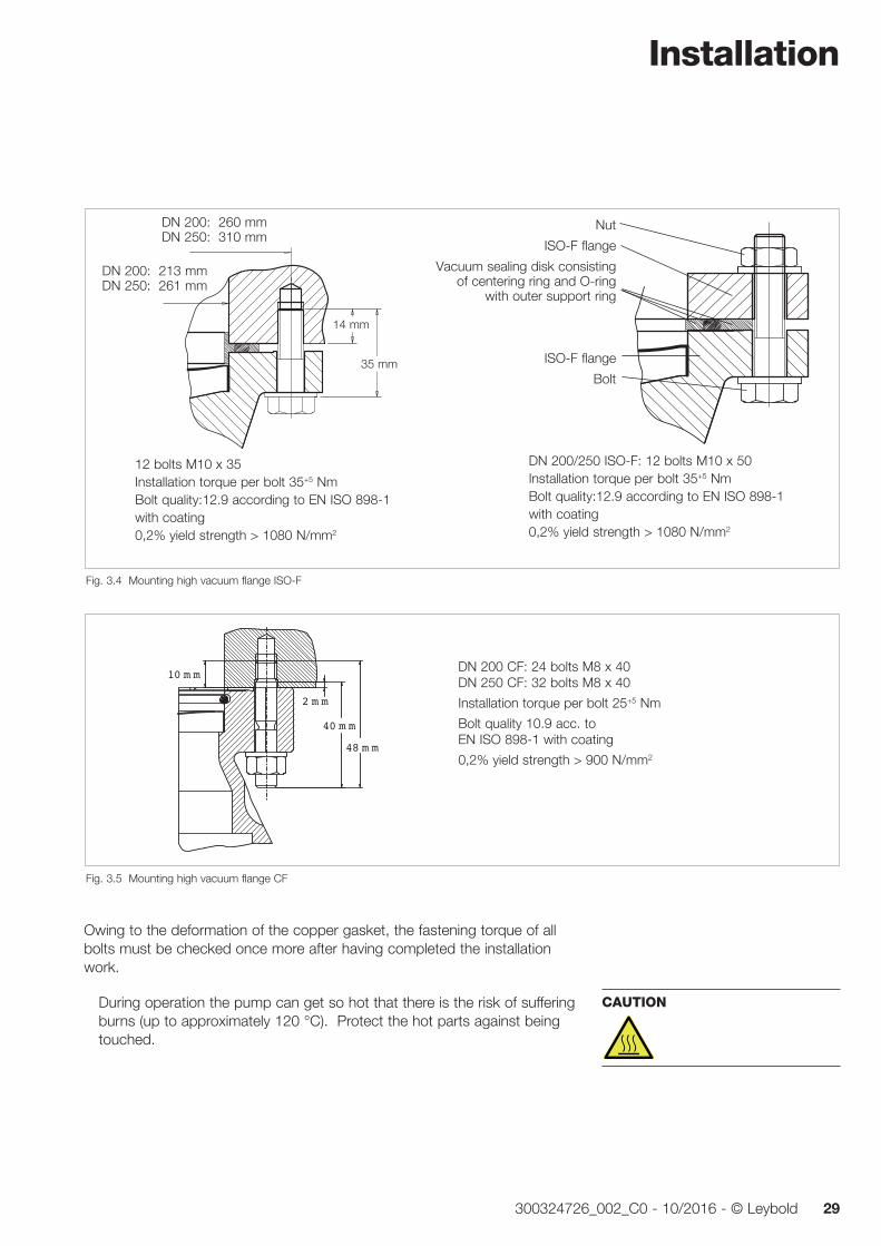
Flange mounting for ISO-F flangesMount the turbomolecular pump according to Fig 3.4 and tighten the bolts crosswise step-by-step.
The contact surfaces of pump housing, vacuum system and centering ring must be free of grease and dry so as to ensure adequate strength in case the rotor should seize.
Flange mounting for CF flangesBefore fitting, check to ensure that the sealing edge is undamaged. Do not touch the copper gasket and the sealing edge with your bare hands.
The contact surfaces of pump housing, vacuum system and centering ring must be free of grease and dry so as to ensure adequate strength in case the rotor should seize.
Mount the turbomolecular pump according to Fig 3.5 and tighten the bolts crosswise step-by-step.
When the pump shall be baked out, the threads of the bolts should have been lubricated with a high temperature lubricant.
NOTICE
NOTICE
NOTICE
Fig. 3.3 Installing the inlet screen
Correct
Wrong
NOTICEInstall the inlet screen as shown. Installing the inlet screen upside down may lead to contact bet-ween inlet screen and rotor duri-ng fast venting of the pump.
Installation
29300324726_002_C0 - 10/2016 - © Leybold
Owing to the deformation of the copper gasket, the fastening torque of all bolts must be checked once more after having completed the installation work.
During operation the pump can get so hot that there is the risk of suffer ing burns (up to approximately 120 °C). Protect the hot parts against being touched.
CAUTION
Fig. 3.4 Mounting high vacuum flange ISO-F
DN 200: 260 mmDN 250: 310 mm
DN 200: 213 mmDN 250: 261 mm
14 mm
35 mm
DN 200/250 ISO-F: 12 bolts M10 x 50Installation torque per bolt 35+5 NmBolt quality:12.9 according to EN ISO 898-1 with coating0,2% yield strength > 1080 N/mm2
Nut
ISO-F flange
Vacuum sealing disk consisting of centering ring and O-ring
with outer support ring
ISO-F flange
Bolt
Fig. 3.5 Mounting high vacuum flange CF
48 m m
40 m m
2 m m
10 m m DN 200 CF: 24 bolts M8 x 40 DN 250 CF: 32 bolts M8 x 40
Installation torque per bolt 25+5 Nm
Bolt quality 10.9 acc. to EN ISO 898-1 with coating
0,2% yield strength > 900 N/mm2
12 bolts M10 x 35Installation torque per bolt 35+5 NmBolt quality:12.9 according to EN ISO 898-1 with coating0,2% yield strength > 1080 N/mm2
Installation
30 300324726_002_C0 - 10/2016 - © Leybold
3.4 Forevacuum connectionThe high vacuum pressure level which can be achieved is a function of the volume of gas flow Q to be pumped and the forevacuum pressure.
We recommend using our two stage TRIVAC-B pumps or dry compressing pumps as backing pumps.
Connect the clean forevacuum line. The connecting flanges must be clean and undamaged. The cross section of this line must be so wide that safe opera tion of the pump can be ensured.
The forevacuum line must be tight. Hazardous gases can escape at leaks or the gases being pumped can react with air or humidity. Observe Safety Information 0.4.6.
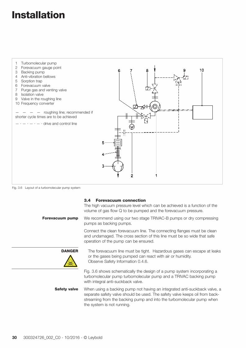
Fig. 3.6 shows schematically the design of a pump sys tem incorporating a turbomolecular pump turbomolecular pump and a TRIVAC backing pump with integral anti-suckback valve.
When using a backing pump not having an integrated an ti-suckback valve, a separate safety valve should be used. The safety valve keeps oil from back-streaming from the backing pump and into the turbomolecular pump when the system is not running.
Forevacuum pump
DANGER
Safety valve
Fig. 3.6 Layout of a turbomolecular pump system
1 Turbomolecular pump2 Forevacuum gauge point3 Backing pump4 Anti-vibration bellows5 Sorption trap6 Forevacuum valve7 Purge gas and venting valve8 Isolation valve9 Valve in the roughing line10 Frequency converter
— — — — roughing line; recommended if shorter cycle times are to be achieved
— · — · — · — · drive and control line
Installation
31300324726_002_C0 - 10/2016 - © Leybold
To ensure that the forevacuum space at the turbomolecular pump is kept largely free of oil vapors during operation, as well, we recommend installing an adsorption trap in the forevacuum line. Alternatively purge the forevacuum line with inert gas. In this case the pressure in the forevacuum line must be over 10-2 mbar.
Provide a roughing line to achieve the shortest cycle times.
Ensure that the pump is sufficiently isolated against vibrations generated by the forevacuum pump.
No forces from the piping system may be allowed to affect the turbomolecu-lar pump. Support the piping correspondingly or decouple through flexible joints.
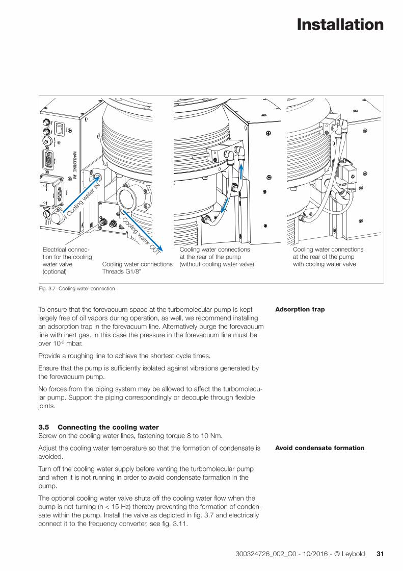
3.5 Connecting the cooling waterScrew on the cooling water lines, fastening torque 8 to 10 Nm.
Adjust the cooling water temperature so that the formation of condensate is avoided.
Turn off the cooling water supply before venting the turbomolecular pump and when it is not running in order to avoid condensate formation in the pump.
The optional cooling water valve shuts off the cooling water flow when the pump is not turning (n < 15 Hz) thereby preventing the formation of conden-sate within the pump. Install the valve as depicted in fig. 3.7 and electrically connect it to the frequency converter, see fig. 3.11.
Adsorption trap
Avoid condensate formation
Fig. 3.7 Cooling water connection
Cooling water OUT
Coolin
g wate
r IN
Cooling water connections at the rear of the pump (without cooling water valve)
Electrical connec-tion for the cooling water valve (optional)
Cooling water connectionsThreads G1/8”
Cooling water connections at the rear of the pump with cooling water valve
Installation
32 300324726_002_C0 - 10/2016 - © Leybold
If immediate pump shut-down in case of cooling water supply failure is re quired, then a flow monitor will have to be inserted in the drain line. If you do not close the cooling water it may take longer to achieve ultimate pres-sure after start up of the system.
When decommissioning the pump, drain out the cooling water and blow out the cooling water lines so as to avoid frost damage.
Do not open or modify the cooling water connections at the rear of the pump.
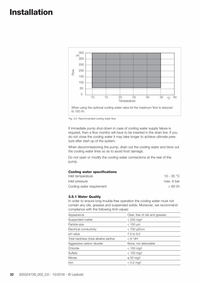
Cooling water specificationsInlet temperature 10 - 35 °C
Inlet pressure max. 6 bar
Cooling water requirement > 60 l/h
3.5.1 Water QualityIn order to ensure long trouble-free operation the cooling water must not contain any oils, greases and suspended solids. Moreover, we recommend compliance with the following limit values:
Appearance Clear, free of oils and greases
Suspended matter < 250 mg/l
Particle size < 150 µm
Electrical conductivity < 700 µS/cm
pH value 7.0 to 9,0
Total hardness (total alkaline earths) < 8 °dH
Aggressive carbon dioxide None, not detectable
Chloride < 100 mg/l
Sulfate < 150 mg/l
Nitrate ≤ 50 mg/l
Iron < 0.2 mg/l
350
300
250
200
150
100
50
0
l/h
10 20 25 3015 °C35 40
Flow
Temperature
Fig. 3.8 Recommended cooling water flow
When using the optional cooling water valve kit the maximum flow is reduced to 150 l/h.
Installation
33300324726_002_C0 - 10/2016 - © Leybold
Manganese < 0.1 mg/l
Ammonium < 1.0 mg/l
Free chlorine < 0.2 mg/l
8 °dH (degrees German hardness) = 1.4mmol/l = 10 °e (degrees English hardness) = 14 °f (degrees French hardness)
If there is the danger of frost, you may use a water glycol mixture of up to 30 %.
DS water (softened or fully desalinated water) can be used for cooling the pump, if the pH value corresponds to the range indicated above.
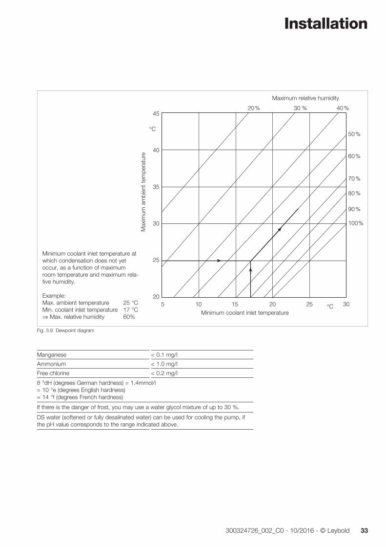
30°C
45
40
35
30
25
20
°C
20 %
50 %
100 %
90 %
70 %
80 %
60 %
30 % 40 %
5 10 15 20 25
Minimum coolant inlet temperature at which condensation does not yet occur, as a function of maximum room temperature and maximum rela-tive humidity.
Example: Max. ambient temperature 25 °CMin. coolant inlet temperature 17 °C⇒ Max. relative humidity 60%
Maximum relative humidity
Max
imum
am
bien
t te
mpe
ratu
re
Minimum coolant inlet temperature
Fig. 3.9 Dewpoint diagram
Installation
34 300324726_002_C0 - 10/2016 - © Leybold
Sperrgas- und Belüftungsventil
G1/4"
Übergangs-Zentrierring DN 10/16 KF
DN 10 KF
Anschluss Gasseite
PURGE/VENT
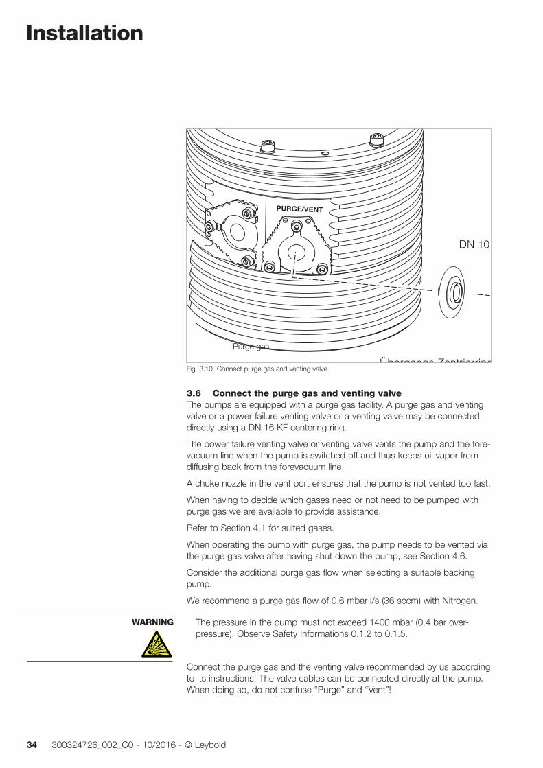
Fig. 3.10 Connect purge gas and venting valve
Purge gas
3.6 Connect the purge gas and venting valveThe pumps are equipped with a purge gas facility. A purge gas and venting valve or a power failure venting valve or a venting valve may be connected directly using a DN 16 KF centering ring.
The power failure venting valve or venting valve vents the pump and the fore-vacuum line when the pump is switched off and thus keeps oil vapor from diffusing back from the forevacuum line.
A choke nozzle in the vent port ensures that the pump is not vented too fast.
When having to decide which gases need or not need to be pumped with purge gas we are available to provide assistance.
Refer to Section 4.1 for suited gases.
When operating the pump with purge gas, the pump needs to be vented via the purge gas valve after having shut down the pump, see Section 4.6.
Consider the additional purge gas flow when selecting a suitable backing pump.
We recommend a purge gas flow of 0.6 mbar·l/s (36 sccm) with Nitrogen.
The pressure in the pump must not exceed 1400 mbar (0.4 bar over-pressure). Observe Safety Informations 0.1.2 to 0.1.5.
Connect the purge gas and the venting valve recommended by us according to its instructions. The valve cables can be connected directly at the pump. When doing so, do not confuse “Purge” and “Vent”!
WARNING
Installation
35300324726_002_C0 - 10/2016 - © Leybold
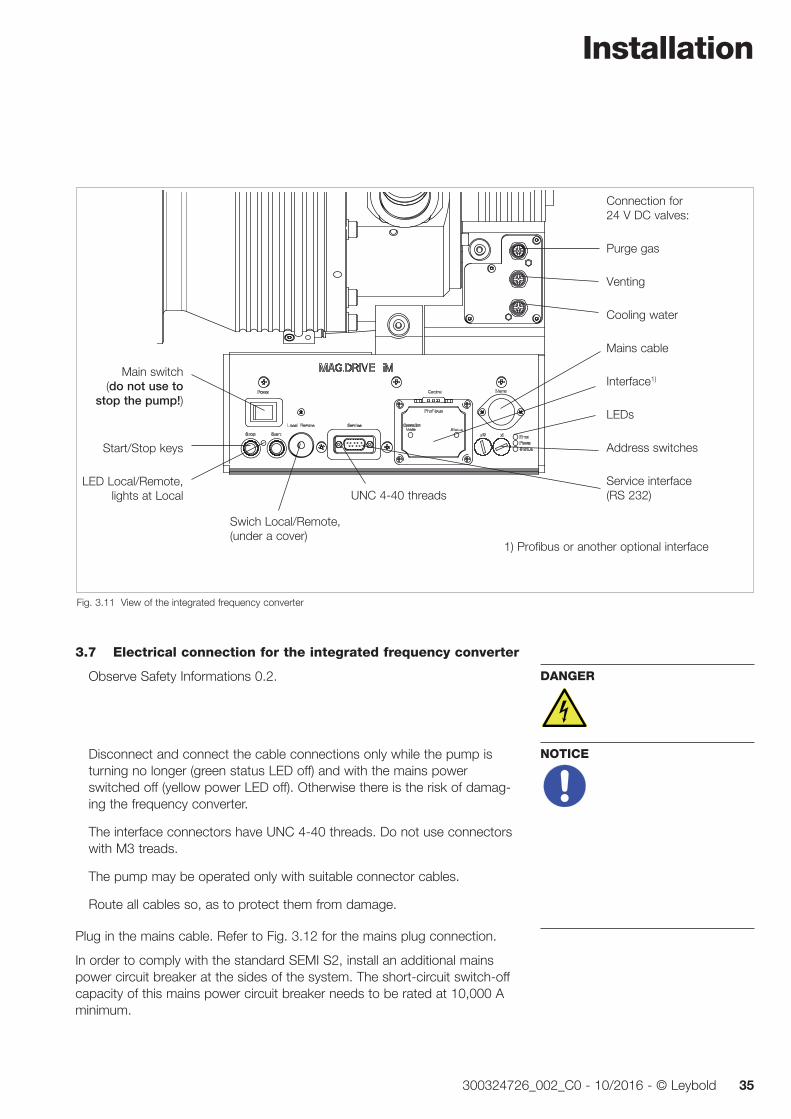
3.7 Electrical connection for the integrated frequency converter
Observe Safety Informations 0.2.
Disconnect and connect the cable connections only while the pump is turning no longer (green status LED off) and with the mains power switched off (yellow power LED off). Other wise there is the risk of damag-ing the frequency converter.
The interface connectors have UNC 4-40 threads. Do not use connectors with M3 treads.
The pump may be operated only with suitable connector cables.
Route all cables so, as to protect them from damage.
Plug in the mains cable. Refer to Fig. 3.12 for the mains plug connection.
In order to comply with the standard SEMI S2, install an additional mains power circuit breaker at the sides of the system. The short-circuit switch-off capacity of this mains power circuit breaker needs to be rated at 10,000 A minimum.
DANGER
NOTICE
Fig. 3.11 View of the integrated frequency converter
UNC 4-40 threads
1) Profibus or another optional interface
Connection for 24 V DC valves:
Purge gas
Venting
Cooling water
Mains cable
Interface1)
LEDs
Address switches
Service interface (RS 232)
Main switch (do not use to
stop the pump!)
Start/Stop keys
LED Local/Remote, lights at Local
Swich Local/Remote, (under a cover)
Installation
36 300324726_002_C0 - 10/2016 - © Leybold
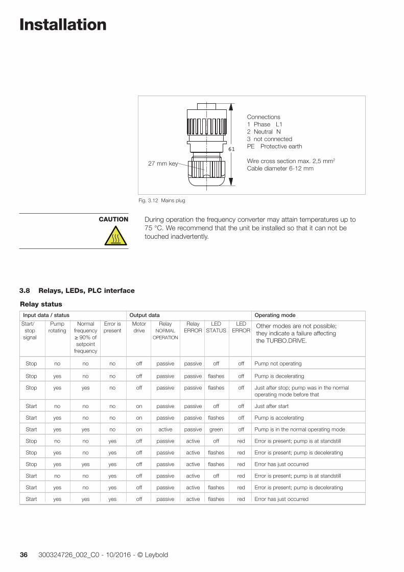
During operation the frequency converter may attain temperatures up to 75 °C. We recommend that the unit be installed so that it can not be touched inadvertently.
CAUTION
Relay status
Input data / status Output data Operating mode
Start/ Pump Normal Error is Motor Relay Relay LED LED stop rotating frequency present drive NORMAL ERROR STATUS ERROR signal ≥ 90% of OPERATION setpoint frequency
Stop no no no off passive passive off off Pump not operating
Stop yes no no off passive passive flashes off Pump is decelerating
Stop yes yes no off passive passive flashes off Just after stop; pump was in the normal operating mode before that
Start no no no on passive passive off off Just after start
Start yes no no on passive passive flashes off Pump is accelerating
Start yes yes no on active passive green off Pump is in the normal operating mode
Stop no no yes off passive active off red Error is present; pump is at standstill
Stop yes no yes off passive active flashes red Error is present; pump is decelerating
Stop yes yes yes off passive active flashes red Error has just occurred
Start no no yes off passive active off red Error is present; pump is at standstill
Start yes no yes off passive active flashes red Error is present; pump is decelerating
Start yes yes yes off passive active flashes red Error has just occurred
Other modes are not possible; they indicate a failure affecting the TURBO.DRIVE.
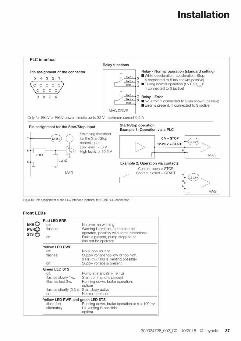
3.8 Relays, LEDs, PLC interface
61
SW 27
Fig. 3.12 Mains plug
Connections1 Phase L12 Neutral N3 not connectedPE Protective earth
Wire cross section max. 2,5 mm2
Cable diameter 6-12 mm27 mm key
Installation
37300324726_002_C0 - 10/2016 - © Leybold
Red LED ERR off: No error, no warning flashes: Warning is present, pump can be operated, possibly with some restrictions on: Fault is present, pump stopped or can not be operated
Yellow LED PWR off: No supply voltage flashes: Supply voltage too low or too high, 9 Hz <n <100Hz (venting possible) on: Supply voltage is present
Green LED STS off: Pump at standstill (< 9 Hz) flashes slowly 1/s: Start command is present (flashes fast 3/s: Running down, brake operation: option) flashes shortly (0.3 s): Start delay active on: Normal operation
Yellow LED PWR and green LED STS (flash fast Running down, brake operation at n < 100 Hz alternately i.e. venting is possible: option)
Front LEDs
Relay functions
8 7 6
5 4 3 2 1
9
Pin assignment of the connector
534
n. c.n. o.com .
291
n. c.n. o.com .
Relay - Normal operation (standard setting) While deceleration, acceleration, Stop:
4 connected to 5 (as shown; passive) During normal operation (f > 0,9·fnom.):
4 connected to 3 (active)
Relay - Error No error: 1 connected to 2 (as shown; passive) Error is present: 1 connected to 9 (active)
Fig.3.13 Pin assignment of the PLC interface (optional for CONTROL connector)
MAG.DRIVE
12-15 V
1.8 kΩ3.3 kΩ
MAG 300
7
8
6
MAG 300
786
0 V = STOP12-24 V = START
MAG 300
786
12-15 V
12-15 V
Pin assignment for the Start/Stop input
Switching threshold for the Start/Stop control input:Low level: < 8 VHigh level: > 10.5 V
Start/Stop operationExample 1: Operation via a PLC
Contact open = STOPContact closed = START
Example 2: Operation via contacts
PLC interface
Only for SELV or PELV power circuits up to 32 V, maximum current 0.5 A
0 V = STOP
12-24 V = START
MAG
MAG
MAG
Operation
38 300324726_002_C0 - 10/2016 - © Leybold
4 Operation
4.1 Media compatibility / purge gasThe MAG turbomolecular pumps are suitable for pumping air and clean gases.
The MAG ... iP have a purge gas device.
We would be glad to consult with you as regards the media which can safely be handled with this unit.
Install a micropore filter when pumping media which contains dust.
Suited for venting or purging are all gases,
which will not cause corrosion or pitting in aluminium and steel and
which in connection with process deposits in the pump will not cause cor-rosion or sticking.
For venting and as the purge gas we recommend inert gases like nitrogen or argon. The temperature of these gases should be between 5 °C and 80 °C, max. relative humidity should not exceed 10 ppm.
The gas must be clean.
In individual cases and after consultation also dry, filtered, oil-free air or fil-tered ambient air may be used (filter mesh < 1µm).
Change the filters after some time, at least annually.
4.2 InterfacesThe MAG.DRIVE can optionally be equipped with the following interfaces:
RS 232 RS 485 Profibus PLC (9-pin Sub-D) Ethernet/IP (1-port) EtherCat (in preparation)
If the interface modules are not covered, they will comply with type of protec-tion IP 30, with cover to IP 54. The remainder of the pump and the frequency converter will in the case of properly connected cables always comply with IP 54.
If you try to control via two installed interfaces, the interface in the CONTROL slot will have the higher priority.
The address for the Fieldbus module can be set via the RS 232 service inter-face or at the address switches.
The set default address is 126dec = 7Ehex.
Suited gases
Type of protection
Operation
39300324726_002_C0 - 10/2016 - © Leybold
4.3 Switching onSwitch on the backing pump.
Switch on the main switch. The Power ON LED will light green.
During an initialisation phase of approximately 45 seconds all LEDs at the fre-quency converter will light up alternatingly, thereafter the yellow LED will come on.
Switch on the turbomolecular pump
by pressing the START button (in the LOCAL mode)
via the interface, e.g. Profibus
The turbomolecular pump runs up. The green LED flashes. When the pump reaches normal operation the green LED lights up permanently.
The backing pump and the MAG can be switched on simultaneously. In such a situation the turbomolecular pump serves from the very outset as an effec-tive baffle.
If the turbomolecular pump is to be switched on after a certain delay period, pre-evacuation can take place through the turbomolecular pump even though it is not running.
Do not open the turbomolecular pump suddenly to a previously evacuated vacuum chamber or to a large-volume forevacuum line which has already been evacuated. The pressure surge can press against the rotor into the limiting bearing, causing accelerated wear at that bearing.
4.4 OperationThe magnetic bearing in the MAG are immune to wear. In addition to the magnetic bearings, the MAG is equipped with touch-down bearings which protect the rotor against mechanical contact with the stator if the pump is subjected to external shock loading or when the pump is switched off. These touch-down bearings have a limited service life. Please observe the following in order to obtain maximum service life.
Avoid shock and vibrations (e.g. from other pumps) when the pump is run-ning. Shocks are particularly harmful. If the pump appears to be running in the mechanical bearings continuously it is switched off.
Avoid a frequent switching on and off.
Do not suddenly expose the MAG to an already evacuated vacuum cham-ber. The pressure surge may cause the rotor to make contact with the touch-down bearings. This will cause increased wear.
Do not stop the Mag with the mains. Use a stop command. Switching off the mains while the pump is running will wear out the touch down bear-ings. If the mains supply has been disconnected accidently re-connect it.
NOTICE
Protecting the touch-down bearings
Operation
40 300324726_002_C0 - 10/2016 - © Leybold
4.5 Switching off Switch off the pump
by pressing the STOP button (in the LOCAL mode)
via the interface, e.g. Profibus
Do not stop the Mag with the mains. Switching off the mains while the pump is running will wear out the touch down bear ings.
After switching off, the green status LED will flash until the rotor of the turbo-molecular pump is at standstill. This may take several minutes. The decelera-tion time of the pump corresponds approximately to the run-up time of the pump. The rotor may be stopped faster by venting the pump. The pump must only be handled with the rotor not rotating.
With the DC power supply off, the turbomolecular pump will act as a genera-tor supplying the frequency converter with energy as indicated by the yellow power LED.
At speeds approximately below 100 Hz there will not be enough power any more for the LEDs, i.e. the pump may still turn with out any of the LEDs being on.
Switch off the forevacuum pump.
When using oil-sealed forevacuum pumps, vent the turbomolecular pump before it comes to a stop; refer to Section 4.6.
When using TRIVAC pumps the built-in anti-suckback valve will close auto-matically, shutting off the forevacuum line. In forevacuum pumps without a vacuum retention valve, close the valve in the forevacuum line.
When the system is not operating, ensure that neither ambient air nor cleaning media can enter the pump.
If a failure occurs the turbomolecular pump will be shut down automatically. The red LED at the frequency converter lights up.
After a mains power failure the pump can run up automatically once more. This is intended to keep the vacuum during short mains failures. The oper-ator must ensure safety by suitable measures.
Unplug any connectors only when the mains voltage is switched off and the pump does no longer turn (the green LED is off).
Emergency shut downIn the case of an emergency shut down, the pump is switched off as de scribed above. The rotor of the turbomolecular pump may be stopped faster by controlled venting the pump, see Fig. 4.1.
NOTICE
CAUTION
Venting
CAUTION
Operation
41300324726_002_C0 - 10/2016 - © Leybold
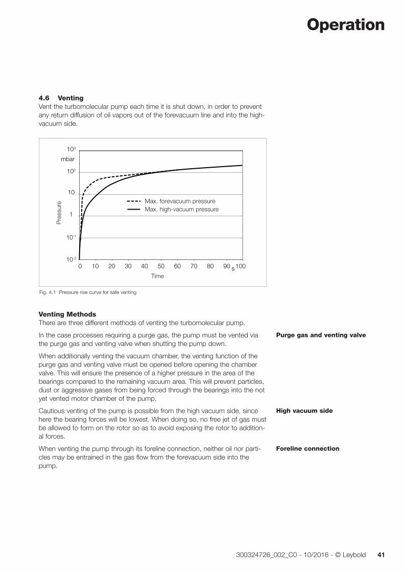
4.6 VentingVent the turbomolecular pump each time it is shut down, in order to prevent any return diffusion of oil vapors out of the forevacuum line and into the high-vacuum side.
Dru
ck
Zeit
10-2
10-1
1
10
102
103
0 10 20 30 40 50 60 70 80 90 100
Max. VorvakuumdruckMax. Hochvakuumdruck
mbar
s
Fig. 4.1 Pressure rise curve for safe venting
Time
Pre
ssur
e Max. forevacuum pressureMax. high-vacuum pressure
Venting MethodsThere are three different methods of venting the turbomolecular pump.
In the case processes requiring a purge gas, the pump must be vented via the purge gas and venting valve when shutting the pump down.
When additionally venting the vacuum chamber, the venting function of the purge gas and venting valve must be opened before opening the chamber valve. This will ensure the presence of a higher pressure in the area of the bearings compared to the remaining vacuum area. This will prevent particles, dust or aggressive gases from being forced through the bearings into the not yet vented motor chamber of the pump.
Cautious venting of the pump is possible from the high vacuum side, since here the bearing forces will be lowest. When doing so, no free jet of gas must be allowed to form on the rotor so as to avoid exposing the rotor to addition-al forces.
When venting the pump through its foreline connection, neither oil nor parti-cles may be entrained in the gas flow from the forevacuum side into the pump.
Purge gas and venting valve
High vacuum side
Foreline connection
Operation
42 300324726_002_C0 - 10/2016 - © Leybold
Speed of the Pressure RiseAll turbomolecular pumps may be vented at full speed. However, the pres-sure must not increase faster than specified through the pressure rise curve, see Fig. 4.1.
The pump must be vented significantly slower when there is the risk of parti-cles entering into the pump from the process. During venting, the flow must be of the laminar type in both the vacuum chamber and the turbomolecular pump.
The speed of the pressure rise during venting of the running pump will great ly influence the load on the rotor/stator pack and the bearings. The slower the pump is vented, the longer the service life of the bearings will be.
The pump must not be vented to pressures above atmospheric pressure.
4.7 Removing the pump from the systemShut down the pump and vent as described in Sections 4.5 and 4.6.
If the pump has previously handled hazardous gases, implement the prop-er precautionary measures before opening the intake or exhaust connec-tion. Observe Safety Informations 0.4.7.
Disconnect the pump only when it has come to a full stop. The green LED at the frequency converter must have gone out.
Then switch the mains power off and wait until the yellow power LED is off. Then only disconnect any cable connections.
Drain out the cooling water and blow out the cooling water lines so as to avoid frost damage.
The pumps may be contaminated with process gases. These gases may be toxic and hazardous to health. In addition, deposits with similarly dangerous properties may have formed. Many of these gases and deposits form acids when they come into contact with humid air. This will result in serious corro-sion damage to the pump.
To avoid health hazards and corrosion damage when the pumps are detached from the system, fasten a container of desiccant under the trans-port cover of the high-vacuum connection and then close the pump immedi-ately at all flange connections. Store the pump, with a desiccant, in an air-tight PE bag.
Corrosion damage due to faulty packing will nullify the guarantee.
Pack the pump so that it cannot be damaged during shipping and storage. Pay particular attention to protection for the flanges and the electrical plug.
Observe the instructions in Section 5.3 if you forward the pump to Leybold.
Speed
Pressure rise curve
Particles
DANGERDANGER
Drain cooling water
Hazardous gases
Deposits
Desiccant
Maintenance
43300324726_002_C0 - 10/2016 - © Leybold
5 MaintenanceWe recommend an exchange of the rotor unit after 80,000 operating hours or 20,000 cycles at the latest.
Such maintenance work can only be done by the Leybold Service. If required contact the Leybold service center nearest to your location. You can find the address on our internet page www.leybold.com.
At high pump loads - for example during cyclic opera tion, at high gas through puts or at high ambient temperatures - the aforementioned mainte-nance work should be carried forward. Please consult Leybold for recom-mendations.
Observe Safety information 0.1.7.
Depending on the degree of contamination of the purge gas used the filter will clog and will have to be ex changed (our experience indicates that this will become necessary after 1 to 6 months).
When an adsorption trap is used, regenerate or renew the adsorption agent regularly; refer to the operating instructions provided with the trap.
5.1 CleaningIf required clean the turbomolecular pump of dust with a dry cloth.
Rotor exchange
WARNING
Purge gas filter
Adsorption trap
Maintenance
44 300324726_002_C0 - 10/2016 - © Leybold
5.2 Changing the touch-down bearingsWear occurs at the touch-down bearings when hard shocks have to be sup-ported.
The frequency converter outputs a warning and then an error message if the touch-down bearings have had contact too often or for a too long time (def-ault 1000 contacts or 1 hour). In this case maintenance is required.
Only the Leybold service can change the touch-down bear ings.
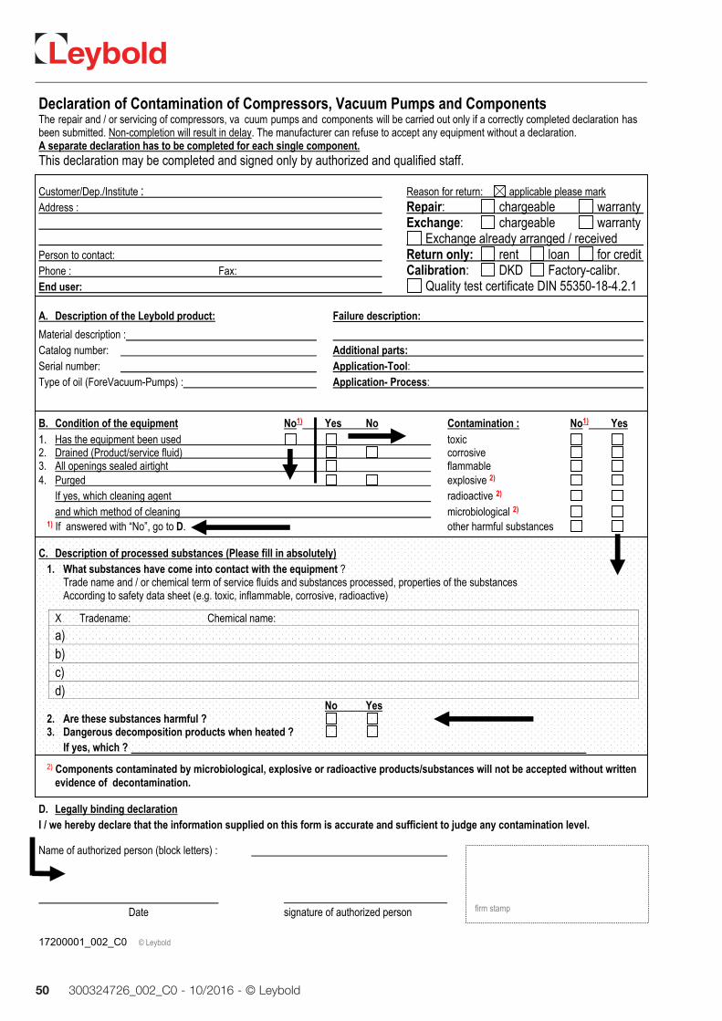
5.3 Leybold ServiceWhenever you send us in equipment, indicate whether the equipment is con-taminated or is free of substances which could pose a health hazard. If it is contaminated, specify exactly which substances are involved. You must use the form we have prepared for this purpose.
A copy of the form has been reproduced at the end of these Operating Instructions: “Declaration of Contamination for Compressors, Vacuum Pumps and Components”. Another suitable form is available from www.leybold.com Documents Download Documents.
Attach the form to each pump.
This statement detailing the type of contamination is required to satisfy legal requirements and for the protection of our employees.
We must return to the sender any equipment which is not accompanied by a contamination statement.
Contamination
Form
Troubleshooting
45300324726_002_C0 - 10/2016 - © Leybold
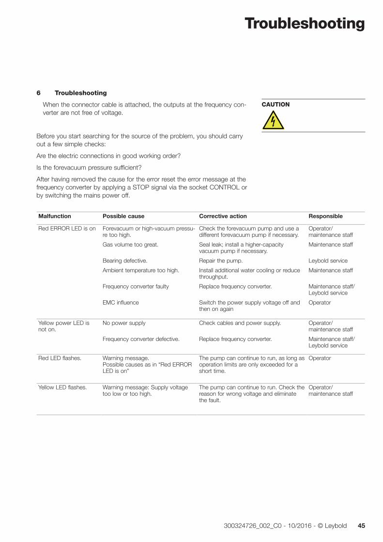
6 Troubleshooting
When the connector cable is attached, the outputs at the frequency con-verter are not free of voltage.
Before you start searching for the source of the problem, you should carry out a few simple checks:
Are the electric connections in good working order?
Is the forevacuum pressure sufficient?
After having removed the cause for the error reset the error message at the frequency converter by applying a STOP signal via the socket CONTROL or by switching the mains power off.
Malfunction Possible cause Corrective action Responsible
Red ERROR LED is on Forevacuum or high-vacuum pressu-re too high.
Gas volume too great.
Bearing defective.
Ambient temperature too high.
Frequency converter faulty
EMC influence
Check the forevacuum pump and use a different forevacuum pump if necessary.
Seal leak; install a higher-capacity vacuum pump if necessary.
Repair the pump.
Install additional water cooling or reduce throughput.
Replace frequency converter.
Switch the power supply voltage off and then on again
Operator/ maintenance staff
Maintenance staff
Leybold service
Maintenance staff
Maintenance staff/ Leybold service
Operator
Yellow power LED is not on.
No power supply
Frequency converter defective.
Check cables and power supply.
Replace frequency converter.
Operator/ maintenance staff
Maintenance staff/ Leybold service
Red LED flashes. Warning message. Possible causes as in “Red ERROR LED is on”
The pump can continue to run, as long as operation limits are only exceeded for a short time.
Operator
Yellow LED flashes. Warning message: Supply voltage too low or too high.
The pump can continue to run. Check the reason for wrong voltage and eliminate the fault.
Operator/ maintenance staff
CAUTION
Troubleshooting
46 300324726_002_C0 - 10/2016 - © Leybold
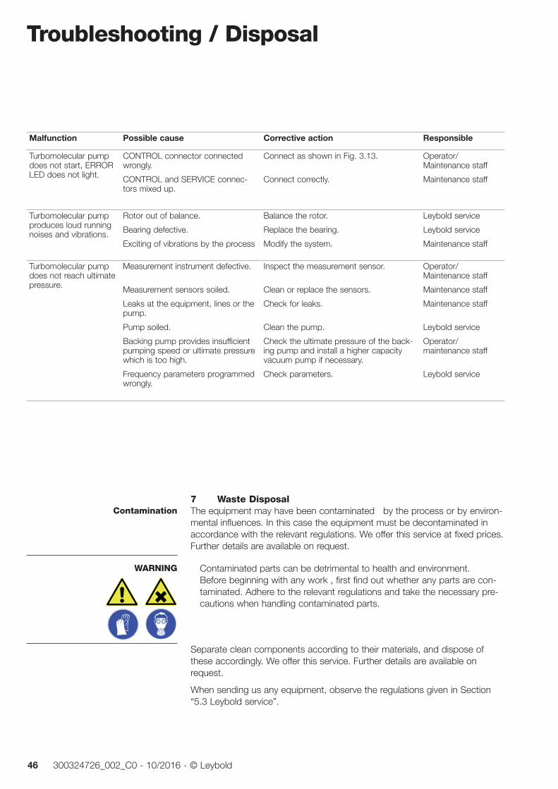
Malfunction Possible cause Corrective action Responsible
Turbomolecular pump does not start, ERROR LED does not light.
CONTROL connector connected wrongly.
CONTROL and SERVICE connec-tors mixed up.
Connect as shown in Fig. 3.13.
Connect correctly.
Operator/ Maintenance staff
Maintenance staff
Turbomolecular pump produces loud running noises and vibrations.
Rotor out of balance.
Bearing defective.
Exciting of vibrations by the process
Balance the rotor.
Replace the bearing.
Modify the system.
Leybold service
Leybold service
Maintenance staff
Turbomolecular pump does not reach ultimate pressure.
Measurement instrument defective.
Measurement sensors soiled.
Leaks at the equipment, lines or the pump.
Pump soiled.
Backing pump provides insufficient pumping speed or ultimate pressure which is too high.
Frequency parameters programmed wrongly.
Inspect the measurement sensor.
Clean or replace the sensors.
Check for leaks.
Clean the pump.
Check the ultimate pressure of the back-ing pump and install a higher capacity vacuum pump if necessary.
Check parameters.
Operator/ Maintenance staff
Maintenance staff
Maintenance staff
Leybold service
Operator/ maintenance staff
Leybold service
7 Waste DisposalThe equipment may have been contaminated by the process or by environ-mental influences. In this case the equipment must be decontaminated in accordance with the relevant regulations. We offer this service at fixed prices. Further details are available on request.
Contaminated parts can be detrimental to health and environment. Before beginning with any work , first find out whether any parts are con-taminated. Adhere to the relevant regulations and take the necessary pre-cautions when handling contaminated parts.
Separate clean components according to their materials, and dispose of these accordingly. We offer this service. Further details are available on request.
When sending us any equipment, observe the regulations given in Section “5.3 Leybold service”.
Contamination
WARNING
Troubleshooting / Disposal
47300324726_002_C0 - 10/2016 - © Leybold
EC Incorporation Declaration
48 300324726_002_C0 - 10/2016 - © Leybold
EC Declaration of Conformity
49300324726_002_C0 - 10/2016 - © Leybold
CertificatesCertificates
The MAG integra have been tested by the TÜV Rheinland of North America according to the requirements of
UL 61010-1:2012
CAN/CSA-C22.2 NO. 61010-1-12
The components are in compliance to the tested standards.
Test Report No. 31480039.001 Certificate No. CU 72140054 01
The TÜV Rheinland of North America is a “Nationally Recognized Testing Laboratory” (NRTL) for the USA and Canada.
This product has been tested to the requirements of CAN/CSA-C22.2 No. 61010-1, third edition, including Amendment 1, or a later version of the same standard incorporating the same level of testing requirements.
50 300324726_002_C0 - 10/2016 - © Leybold
17200001_002_C0 © Leybold
Declaration of Contamination of Compressors, Vacuum Pumps and Components The repair and / or servicing of compressors, va cuum pumps and components will be carried out only if a correctly completed declaration hasbeen submitted. Non-completion will result in delay. The manufacturer can refuse to accept any equipment without a declaration. A separate declaration has to be completed for each single component.This declaration may be completed and signed only by authorized and qualified staff.
Customer/Dep./Institute : Reason for return: applicable please markAddress : Repair: chargeable warranty Exchange: chargeable warranty Exchange already arranged / received Person to contact: Return only: rent loan for credit Phone : Fax: Calibration: DKD Factory-calibr. End user: Quality test certificate DIN 55350-18-4.2.1
A. Description of the Leybold product: Failure description:
Material description : Catalog number: Additional parts: Serial number: Application-Tool: Type of oil (ForeVacuum-Pumps) : Application- Process:
B. Condition of the equipment No1) Yes No Contamination : No1) Yes
11.. Has the equipment been used toxic 2. Drained (Product/service fluid) corrosive 3. All openings sealed airtight flammable 4. Purged explosive 2)
If yes, which cleaning agent radioactive 2) and which method of cleaning microbiological 2)
1) If answered with “No”, go to D. other harmful substances
C. Description of processed substances (Please fill in absolutely)1. What substances have come into contact with the equipment ?
Trade name and / or chemical term of service fluids and substances processed, properties of the substances According to safety data sheet (e.g. toxic, inflammable, corrosive, radioactive)
X Tradename: Chemical name:
a)
b) c) d)
No Yes2. Are these substances harmful ? 3. Dangerous decomposition products when heated ?
If yes, which ? 2) Components contaminated by microbiological, explosive or radioactive products/substances will not be accepted without written
evidence of decontamination.
D. Legally binding declarationI / we hereby declare that the information supplied on this form is accurate and sufficient to judge any contamination level.
Name of authorized person (block letters) :
Date signature of authorized person
firm stamp
Notes
51300324726_002_C0 - 10/2016 - © Leybold
HeadquarterLeybold GmbHBonner Strasse 498D-50968 CologneT: +49-(0)221-347-0F: +49-(0)[email protected]
GermanyLeybold GmbHSales, Service, Support Center (3SC)Bonner Strasse 498D-50968 CologneT: +49-(0)221-347 1234F: +49-(0)221-347 [email protected]
Leybold GmbHSales Area NorthBranch Office BerlinIndustriestrasse 10bD-12099 BerlinT: +49-(0)30-435 609 0F: +49-(0)30-435 609 [email protected]
Leybold GmbHSales Office SouthBranch Office MunichKarl-Hammerschmidt-Strasse 34D-85609 Aschheim-DornachT: +49-(0)89-357 33 9-10F: +49-(0)89-357 33 [email protected]@leybold.com
Leybold Dresden GmbHService Competence CenterZur Wetterwarte 50, Haus 304D-01109 DresdenService:T: +49-(0)351-88 55 00F: +49-(0)351-88 55 [email protected]
Europe
Belgium
Leybold Nederland B.V.Belgisch bijkantoorLeuvensesteenweg 542-9AB-1930 ZaventemSales:T: +32-2-711 00 83F: +32-2-720 83 [email protected]:T: +32-2-711 00 82F: +32-2-720 83 [email protected]
France
Leybold France S.A.S.Parc du Technopolis, Bâtiment Beta3, Avenue du CanadaF-91940 Les Ulis cedexSales and Service:T: +33-1-69 82 48 00F: +33-1-69 07 57 [email protected]@leybold.com
Leybold France S.A.S.Valence Factory640, Rue A. BergèsB.P. 107F-26501 Bourg-lès-Valence CedexT: +33-4-75 82 33 00F: +33-4-75 82 92 [email protected]
Great Britain
Leybold UK LTD.Unit 9Silverglade Business ParkLeatherhead RoadChessingtonSurrey (London)KT9 2QLSales:T: +44-13-7273 7300F: +44-13-7273 [email protected]:T: +44-13-7273 7320F: +44-13-7273 [email protected]
Italy
Leybold Italia S.r.l.Via Trasimeno 8I-20128 MailandSales:T: +39-02-27 22 31F: +39-02-27 20 96 [email protected]:T: +39-02-27 22 31F: +39-02-27 22 32 [email protected]
Netherlands
Leybold Nederland B.V.Floridadreef 102NL-3565 AM UtrechtSales and Service:T: +31-(30) 242 63 30F: +31-(30) 242 63 [email protected]@leybold.com
Switzerland
Leybold Schweiz AG, PfäffikonChurerstrasse 120CH-8808 PfäffikonWarehouse and shipping address:Riedthofstrasse 214CH-8105 RegensdorfSales:T: +41-44-308 40 50F: +41-44-302 43 [email protected]:T: +41-44-308 40 62F: +41-44-308 40 [email protected]
Spain
Leybold Spain, S.A.C/. Huelva, 7E-08940 Cornellà de Llobregat(Barcelona)Sales:T: +34-93-666 43 11F: +34-93-666 43 [email protected]:T: +34-93-666 46 11F: +34-93-685 43 [email protected]
AmericaUSA
Leybold USA Inc.5700 Mellon RoadUSA-Export, PA 15632T: +1-724-327-5700F: [email protected]:T: +1-724-327-5700F: +1-724-333-1217Service:T: +1-724-327-5700F: +1-724-325-3577
Brazil
Leybold do BrasilRod. Vice-Prefeito Hermenegildo Tonolli,nº. 4413 - 6BDistrito IndustrialJundiaí - SPCEP 13.213-086Sales and Service:T: +55 11 3395 3180F: +55 11 99467 [email protected]@leybold.com
AsiaP. R. China
Leybold (Tianjin)International Trade Co. Ltd.Beichen EconomicDevelopment Area (BEDA),No. 8 Western Shuangchen RoadTianjin 300400ChinaSales and Service:T: +86-22-2697 0808F: +86-22-2697 4061F: +86-22-2697 [email protected]@leybold.com
India
Leybold India Pvt Ltd.No. 82(P), 4th PhaseK.I.A.D.B. PlotBommasandra Industrial AreaBangalore - 560 099IndienSales and Service:T: +91-80-2783 9925F: +91-80-2783 [email protected]@leybold.com
Japan
Leybold Japan Co., Ltd.HeadquartersShin-Yokohama A.K.Bldg., 4th floor3-23-3, Shin-YokohamaKohoku-ku, Yokohama-shiKanawaga 222-0033JapanSales:T: +81-45-471-3330F: [email protected]
Leybold Japan Co., Ltd.Tsukuba Technical Service Center1959, Kami-yokobaTsukuba-shi, Ibaraki-shi 305-0854JapanService:T: +81-29 839 5480F: +81-29 839 [email protected]
Malaysia
Leybold MalaysiaLeybold Singapore Pte Ltd.No. 1 Jalan Hi-Tech 2/6Kulim Hi-Tech ParkKulim, Kedah DarulAman 09000MalaysiaSales and Service:T: +604 4020 222F: +604 4020 [email protected]@leybold.com
South Korea
Leybold Korea Ltd.3F. Jellzone 2 TowerJeongja-dong 159-4Bundang-gu Sungnam-siGyeonggi-doBundang 463-384, KoreaSales:T: +82-31 785 1367F: +82-31 785 [email protected]:623-7, Upsung-DongCheonan-SiChungcheongnam-DoKorea 330-290T: +82-41 589 3035F: +82-41 588 [email protected]
Singapore
Leybold Singapore Pte Ltd.8 Commonwealth Lane #01-01Singapore 149555SingaporeSales and Service:T: +65-6303 7030F: +65-6773 [email protected]@leybold.com
Taiwan
Leybold Taiwan Ltd.No 416-1, Sec. 3Chunghsin Rd., ChutungHsinchu County 310Taiwan, R.O.C.Sales and Service:T: +886-3-500 1688F: +886-3-583 [email protected]@leybold.com
Sales and ServiceLV
_137
86_2
016
10.1
6