Embed Size (px)
DESCRIPTION
Paper presents an overview of MADO, the Mul-tidisciplinary Aircraft Design and Optimizationsoftware package. The package is prepared tolink existing and modified tools to utilize themnext, in an efficient way for optimization. Thetools used in the first stage of development ofMADO were presented. Examples of numericalcomputations are shown - airfoil and the new designed UAVs.
Citation preview

MADO - SOFTWARE PACKAGE FOR HIGH ORDERMULTIDISCIPLINARY AIRCRAFT DESIGN AND
OPTIMIZATION
Tomasz Goetzendorf-Grabowski∗ , Jacek Mieloszyk∗ , Dawid Mieszalski∗∗∗Warsaw University of Technology, Warsaw, Poland ∗∗MSP, Drogomysl, Poland
Keywords: optimization, aircraft design, software
Abstract
Paper presents an overview of MADO, the Mul-tidisciplinary Aircraft Design and Optimizationsoftware package. The package is prepared tolink existing and modified tools to utilize themnext, in an efficient way for optimization. Thetools used in the first stage of development ofMADO were presented. Examples of numericalcomputations are shown - airfoil and the new de-signed UAVs.
1 Introduction
Design of new aircraft is always a challenge.Today’s market demands highly efficient planes,fulfilling challenging missions and often contra-dicting expectations. Thus every project, espe-cially as complex as new design of aircraft, is aset of compromises. Without meeting the goalsfrom many scientific disciplines the aircraft sim-ply won’t fly. If the design requirements are verydemanding it is often hard to propose sufficientproject not using numerical optimization tech-niques [1, 2]. More information on the early stageof the project helps to reduce costs and worktime. This is done by improving the process ofmaking confident decisions, which was consid-ered in the SimSAC[3] project (Fig.1).
One of the main achievements of SimSACproject was development of CEASIOM[4] pack-age, that links many different tools, from geome-try definition, trough aerodynamic computation,mass and inertia analysis, to stability and con-
1
0time
VP
Classical approach
verification inflight tests
verification inground tests
product definition product development
flight testing:- improvement andverification of data,eg. aerodynamic data
ground-facility testing:- design improvement,- design verification,- data-set generation.
represen-tationfidelity
The vision
higher fidelity
earlier
Fig. 1 The idea of cutting time and costs by Sim-SAC [3]
trol issues. This system had to decrease timenecessary to obtain wide knowledge about newdesigned aircraft. MADO goes a step beyondCEASIOM[5]. Collecting experience of Sim-SAC project authors present proposition to linkcurrent tools into global numerical optimizationloop.
2 Main idea of MADO
Engineers have to deal with increasing amount ofdata, which forces the designers to focus on re-peatable activities, not on creative work they arepaid for. Most of these activities can be auto-mated or semi automated depending on the com-plexity of the task and experience of the designer.Very often the disciplines (e.g. aerodynamics,stability and control, strength analysis, etc.) ex-ist separately. The lack of interfaces between thetools, or only one way connections, cause thattranslating data from one solver to another con-
1

T.GOETZENDORF-GRABOWSKI, J.MIELOSZYK & D.MIESZALSKI
sumes most of the work time. Thus even simplestoptimization is not in use. Thanks to softwareenvironment integration it is possible to improvethe design process. The key concept lies in con-nection of main software analyzers (e.g. stabil-ity analyzer, aerodynamic solver, etc.) into onestructure (Fig.2). The designer can make suchconnections from one program to other manu-ally, however it still could consume much time.Depending on skills and experience user can addscripts controlling data flow. The solution is de-veloping easy to use, so-called wrappers, that linktools used in design process into globally man-aged system. Easy way of data transferring re-lieves the designer and will allow to increase hiscreativeness. Many starting points are possible torealize the design task, either from CAD geome-try to numerical analysis, or in an opposite way.Defining the complicated nonlinear geometry ofan aircraft can also be done by author’s innova-tive interface by setting only few design parame-ters. This method can be treated as fast, high levelgeometry definition. The package is thought toextend capabilities of existing software by addingadditional components - commercial or free, usedin the actual institution and linking them into onesuite, which can be used for optimization.
STRENGTH ANALYSIS
FEMSTABILITY & CONTROL
PERFORMANCE
SDSA
AERODYNAMICS
-- MUNK- Mass module- Cx , Cx ...
PANUKL
(inverse problem)
0 f
CAD
CFDVLM
OPTIMIZATION
TRANSLATORS
Fig. 2 Topology of software components andconnections
2.1 Current development state of MADO
The collected software is capable of perform-ing the aerodynamic, structural analyzes basing
on CAD geometry if desired. The package con-tains the component for static and dynamic stabil-ity analysis, which also allows to perform flightsimulation and estimate performance [6]. In thisway we can take into account many project de-tails. All the unique features of presented pack-age, which provide automation, allow to defineoptimization task in a relatively easy way. Gra-dient [7, 8], Monte Carlo [9], Genetic [10] andSwarming [11] optimization algorithms are cur-rently available in the suite. Designer works withuser friendly environment, spending less time onrepeatable activities, without sacrificing flexibil-ity and complexity of the task he defines. Overthe time spent working with the software usercan increase complexity by adding next scien-tific disciplines and increasing number of designvariables. This procedure will lead to better opti-mized solutions.
2.2 Main components of MADO
Current version of MADO contains several com-ponents, that are the standalone applications.However, they can also run in batch mode, whichis very useful to automate optimization process.In the beginning the freeware (or ourself written)applications were taken into account, due to pos-sibility of making necessary changes to run itera-tion without any prompting. Some commercialapplications, which were available for authorswere also initially tested with success (VSAERO,VLAERO by AMI Inc.).
2.2.1 XFOIL
XFOIL [12] is a well known program for the de-sign and analysis of subsonic isolated airfoils, de-veloped by Mark Drela. Possibility to use XFOILin batch mode allowed for easy integration of thesoftware in the optimization loop.
2.2.2 PANUKL
PANUKL is a package for aerodynamic analysisof an aircraft using low order panel method. Thepackage was born in mid nineties and was usedmany times to compute aerodynamic characteris-tics of an aircraft including stability derivatives
2

MADO - SOFTWARE PACKAGE
Fig. 3 PANUKL package
[13]. The package (Fig.3) is being developedall the time, reaching it’s maturity. Current ver-sion [14] contains preprocessor to define geom-etry in an easy way using minimum necessaryparameters, vortex wake generator, solver andpost-processor to view and analyze the compu-tation results. Although pure potential methodsare not able to compute all components of drag,PANUKL can estimate induced drag using Tre-fftz method. The components of PANUKL pack-age can be run in batch mode, what is useful toautomate computations in optimization loop.
2.2.3 SDSA - Simulation and Dynamic Stabil-ity Analyzer
SDSA module was developed as theCEASIOM[5] module however it can berun as a standalone application as well. It
was developed for S&C analysis and is able tocompute stability characteristics using linear andnonlinear model (simulation model) as well [15].
SDSA uses the same Six DoF mathemati-cal nonlinear model of the aircraft motion for allfunctions. For the eigenvalue analysis, the modelis linearized numerically around the equilibrium(trim) point. Eigenvalues and eigenvectors anal-ysis allow automatic recognition of the typicalmodes of motion and their parameters. The flightsimulation module can be used to perform testflights and record flight parameters in real-time.The recorded data can be used for identificationof the typical modes of motions and their param-eters (period, damping coefficient, phase shift).The stability analysis results can be assessed bas-ing on CS/FAR, ICAO, and MIL requirements.
As a module of MADO, it can receive allthe necessary data (aerodynamics, mass, inertia),
3
T.GOETZENDORF-GRABOWSKI, J.MIELOSZYK & D.MIESZALSKI
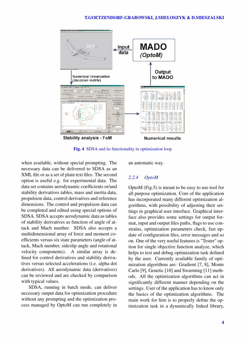
Fig. 4 SDSA and its functionality in optimization loop
when available, without special prompting. Thenecessary data can be delivered to SDSA as anXML file or as a set of plain text files. The secondoption is useful e.g. for experimental data. Thedata set contains aerodynamic coefficients or/andstability derivatives tables, mass and inertia data,propulsion data, control derivatives and referencedimensions. The control and propulsion data canbe completed and edited using special options ofSDSA. SDSA accepts aerodynamic data as tablesof stability derivatives as function of angle of at-tack and Mach number. SDSA also accepts amultidimensional array of force and moment co-efficients versus six state parameters (angle of at-tack, Mach number, sideslip angle and rotationalvelocity components). A similar array is de-fined for control derivatives and stability deriva-tives versus selected accelerations (i.e. alpha dotderivatives). All aerodynamic data (derivatives)can be reviewed and are checked by comparisonwith typical values.
SDSA, running in batch mode, can delivernecessary output data for optimization procedurewithout any prompting and the optimization pro-cess managed by OptoM can run completely in
an automatic way.
2.2.4 OptoM
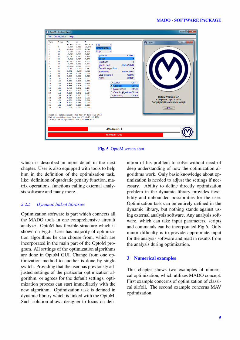
OptoM (Fig.5) is meant to be easy to use tool forall purpose optimization. Core of the applicationhas incorporated many different optimization al-gorithms, with possibility of adjusting their set-tings in graphical user interface. Graphical inter-face also provides some settings for output for-mat, input and output files paths, flags to use con-strains, optimization parameters check, fast up-date of configuration files, error messages and soon. One of the very useful features is "Tester" op-tion for single objective function analyze, whichhelps to test and debug optimization task definedby the user. Currently available family of opti-mization algorithms are: Gradient [7, 8], MonteCarlo [9], Genetic [10] and Swarming [11] meth-ods. All the optimization algorithms can act insignificantly different manner depending on thesettings. User of the application has to know onlythe basics of the optimization algorithms. Themain work for him is to properly define the op-timization task in a dynamically linked library,
4
MADO - SOFTWARE PACKAGE
Fig. 5 OptoM screen shot
which is described in more detail in the nextchapter. User is also equipped with tools to helphim in the definition of the optimization task,like: definition of quadratic penalty function, ma-trix operations, functions calling external analy-sis software and many more.
2.2.5 Dynamic linked libraries
Optimization software is part which connects allthe MADO tools in one comprehensive aircraftanalyze. OptoM has flexible structure which isshown on Fig.6. User has majority of optimiza-tion algorithms he can choose from, which areincorporated in the main part of the OptoM pro-gram. All settings of the optimization algorithmsare done in OptoM GUI. Change from one op-timization method to another is done by singleswitch. Providing that the user has previously ad-justed settings of the particular optimization al-gorithm, or agrees for the default settings, opti-mization process can start immediately with thenew algorithm. Optimization task is defined indynamic library which is linked with the OptoM.Such solution allows designer to focus on defi-
nition of his problem to solve without need ofdeep understanding of how the optimization al-gorithms work. Only basic knowledge about op-timization is needed to adjust the settings if nec-essary. Ability to define directly optimizationproblem in the dynamic library provides flexi-bility and unbounded possibilities for the user.Optimization task can be entirely defined in thedynamic library, but nothing stands against us-ing external analysis software. Any analysis soft-ware, which can take input parameters, scriptsand commands can be incorporated Fig.6. Onlyminor difficulty is to provide appropriate inputfor the analysis software and read in results fromthe analysis during optimization.
3 Numerical examples
This chapter shows two examples of numeri-cal optimization, which utilizes MADO concept.First example concerns of optimization of classi-cal airfoil. The second example concerns MAVoptimization.
5
T.GOETZENDORF-GRABOWSKI, J.MIELOSZYK & D.MIESZALSKI
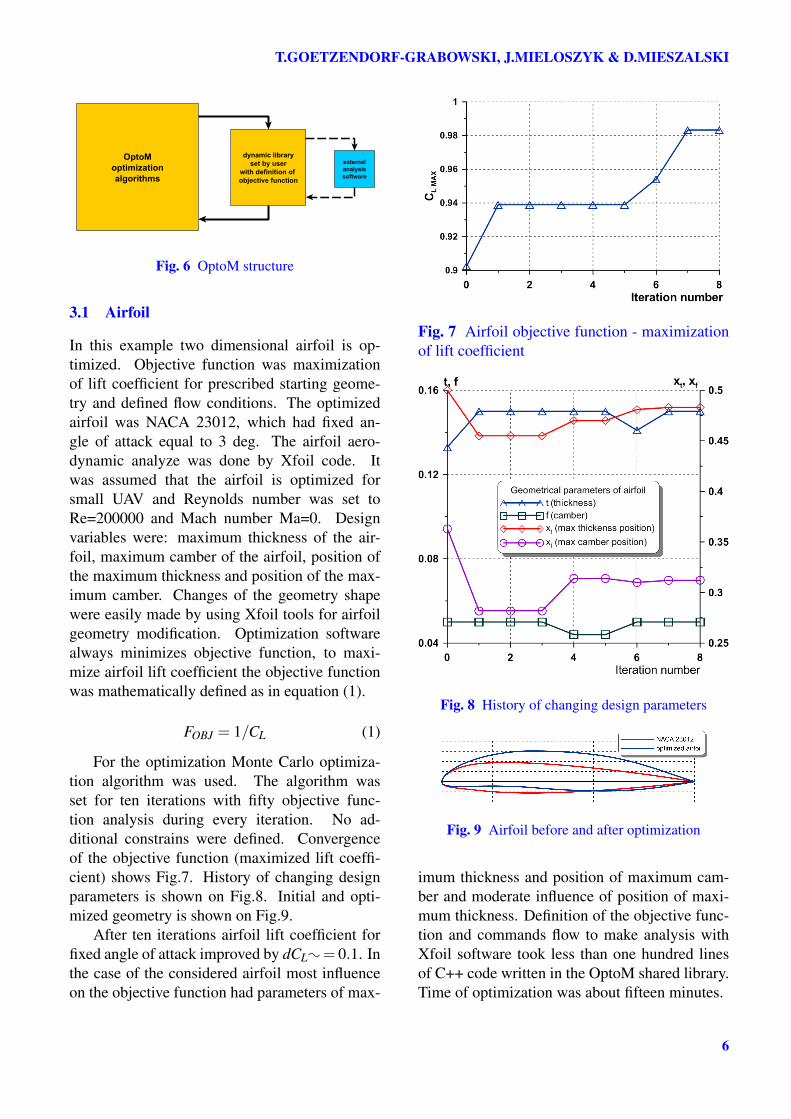
Fig. 6 OptoM structure
3.1 Airfoil
In this example two dimensional airfoil is op-timized. Objective function was maximizationof lift coefficient for prescribed starting geome-try and defined flow conditions. The optimizedairfoil was NACA 23012, which had fixed an-gle of attack equal to 3 deg. The airfoil aero-dynamic analyze was done by Xfoil code. Itwas assumed that the airfoil is optimized forsmall UAV and Reynolds number was set toRe=200000 and Mach number Ma=0. Designvariables were: maximum thickness of the air-foil, maximum camber of the airfoil, position ofthe maximum thickness and position of the max-imum camber. Changes of the geometry shapewere easily made by using Xfoil tools for airfoilgeometry modification. Optimization softwarealways minimizes objective function, to maxi-mize airfoil lift coefficient the objective functionwas mathematically defined as in equation (1).
FOBJ = 1/CL (1)
For the optimization Monte Carlo optimiza-tion algorithm was used. The algorithm wasset for ten iterations with fifty objective func-tion analysis during every iteration. No ad-ditional constrains were defined. Convergenceof the objective function (maximized lift coeffi-cient) shows Fig.7. History of changing designparameters is shown on Fig.8. Initial and opti-mized geometry is shown on Fig.9.
After ten iterations airfoil lift coefficient forfixed angle of attack improved by dCL: = 0.1. Inthe case of the considered airfoil most influenceon the objective function had parameters of max-
Fig. 7 Airfoil objective function - maximizationof lift coefficient
Fig. 8 History of changing design parameters
Fig. 9 Airfoil before and after optimization
imum thickness and position of maximum cam-ber and moderate influence of position of maxi-mum thickness. Definition of the objective func-tion and commands flow to make analysis withXfoil software took less than one hundred linesof C++ code written in the OptoM shared library.Time of optimization was about fifteen minutes.
6

MADO - SOFTWARE PACKAGE
3.2 Bee - mini UAV
In the second example minimization of the aero-dynamic drag was optimized for constant lift co-efficient, with additional constrains put on equi-librium of forces in the aerodynamic z axisand predefined static stability margin. Con-strains were realized by quadratic penalty func-tion. Achieved values of penalties from thecrossed constrains were very big so the objectivefunction was scaled by a factor of one hundred,which is defined by equation (2).
Fob jective = 100CD +P1 +P2 (2)
where:
P1 = 0.5C21/µ
C1 = mg−0.5ρV 2SCL
P2 = 0.5C22/µ
C2 =−0.1−dCm/dCL
Analysis were done utilizing non-viscouspanel code PANUKL[14]. Design variableswere: angle of attack, length of the tip chord,three parameters, which controlled nonlinearwing twist distribution defined as a fourth orderpolynomial center of gravity and four variablesdefining wing tip cut and filet in the middle partof the wing Fig.10.
Fig. 10 Bee wing planform
The first optimization results showed that theoptimization task was over constrained. Solu-tion satisfied stability constrains by varying an-gle of attack, but the geometry parameters didn’tchange significantly maintaining the old geome-try. After this experience variable of position of
Fig. 11 Example of competitive optimization so-lutions
center of gravity was added. This way geometrycould vary still satisfying the constrains.
For optimization genetic and gradient algo-rithms were used, both giving corresponding re-sults. Genetic algorithm was very robust and al-ways gave solutions. Contrary to that experiencegradient algorithm needed quite some time to beset to start the solution to converge, but after itwas done it converged much faster than geneticalgorithm. The best type of gradient solver wassecond order Newton method. Although this al-gorithm needed second order derivatives, its es-timation of search direction was so fine, that itsefficiency overtook Steepest Descent, ConjugateGradient and Quasi Newton gradient methods.Interestingly genetic algorithm, which can theo-retically lead to random solutions, showed thattwo competitive solutions are possible, with thecurrent optimization task definition, with com-pletely different geometry (Fig.11).
The obtained solution, from the first opti-mization tests, revealed a question: are the con-figurations dynamically stable in all modes?
The basic tests of dynamic stability were per-formed and satisfying results were obtained forthe first configuration, with the aft wing sweep(Fig.12). In the next step SDSA is going to run in
7

T.GOETZENDORF-GRABOWSKI, J.MIELOSZYK & D.MIESZALSKI
Fig. 12 Basic modes of motion for analyzed UAV
the optimization loop to satisfy the stability crite-ria "on-line". In the final version authors forecast,that SDSA will be able to modify the decisionvariables or be a part of constraints system.
For the final optimization, which includedmore design parameters and geometry details,Swarming optimization algorithm was used. Thisalgorithm was set for ten iterations with fiftyobjective function analysis during every itera-tion. History of converging objective function isshown on Fig.13. It shows how values of the ob-jective function for the best and the worst individ-ual in the swarm are getting closer. It can be seen,that already in the third iteration objective func-tion, indicating best individual in swarm, merelychanges. Performance of the optimization algo-rithm is very good, what can be observed on theFig.13 with logarithmic objective function axis.
Fig. 13 Objective function versus iteration number
On Fig.14 penalty functions values areshown. After the third iteration they are close to
zero, which means that both constrains are satis-fied with great accuracy.
Fig. 14 Penalty functions values versus iterationnumber
Final geometry with very smooth pressuredistribution after optimization shows Fig.15. Inthe case of the MAV shared library was quite big,but most of the code defined highly nonlinear ge-ometry of the flying object. Pure definition ofthe objective function and commands flow to exe-cute external aerodynamic analysis took less thanone hundred fifty lines of code. This exampleshows that defining optimization task takes lesstime, but ability to define the task in the shareddynamic library gives endless flexibility and al-lows for completion of very demanding tasks.
4 Concluded remarks and further steps
The experience collected so far in the first ex-amples is very promising. Most of the currentMADO tools have user friendly graphical inter-face with novel functionality, which makes it pos-sible to define complicated problems for analyzewith few variables. Great concern is put on easydata exchange between MADO tools, which al-lows to concentrate on the very design. Althoughsoftware maintenance becomes very easy, expe-rienced users will still be able to define com-plicated analyze and optimization tasks withoutlimitations. MADO is meant to be so flexible,that its working capabilities will grow with theknowledge of the user, no matter on what stage
8

MADO - SOFTWARE PACKAGE
Fig. 15 Pressure distribution for the final configuration
of the "know how" he is. In the optimization soft-ware any desired optimization task can be real-ized. The optimization task can be defined en-tirely in the shared library, or incorporate anyexternal analysis software available with batchmode capabilities. Length of the shared librarycode, with analysis, optimization flow control,objective function, constrains and so on, in mostcases will not even exceed 200 lines. Compil-ing only the shared library, containing only theoptimization task and user equipped with addi-tional features to help him define the task enablesfor very effective work. Future of the MADOpackage seems to be bright. The software is con-stantly developed and improved to make it evenmore computationally powerful, intuitive and ef-ficient to work with.
References
[1] Mieloszyk J., "Handling optimization problemson an example of micro UAV", 3rd CEASAir&Space Conference, Venice 2011
[2] Stalewski W., Zółtak J., "Multi-objective and
Multidisciplinary Optimization of Wing forSmall Aircraft", 3rd CEAS Air&Space Confer-ence, Venice 2011
[3] SimSAC - "Simulating Aircraft Stability AndControl Characteristics for Use in ConceptualDesign", Technical Annex to Contract No. FP6-030838, July 17, 2006
[4] von Kaenel R., Rizzi A., Oppelstrup J.,Goetzendorf-Grabowski T., Ghoreyshi M., Cav-agna L., and Berard A. CEASIOM: Simulat-ing Stability & Control with CFD/CSM in Air-craft Conceptual Design, Paper 061, 26th Int’lCongress of the Aeronautical Sciences, Anchor-age, Alaska, Sept 2008.
[5] CEASIOM - Computerised Environment forAircraft Synthesis and Integrated OptimisationMethods, http://www.ceasiom.com/
[6] SDSA - Simulation and Dynamic Sta-bility analysis, Software package,Warsaw University of Technology,http://www.meil.pw.edu.pl/add/ADD/Teaching/Software/SDSA
[7] Nocedal J., Wright S.J. "Numerical Optimiza-tion" Springer, Series in Operations Research,1999
9
T.GOETZENDORF-GRABOWSKI, J.MIELOSZYK & D.MIESZALSKI
[8] Vanderplaats G.N.: Numerical OptimizationTechniques For Engineering Design, McGrawHill, 1984
[9] Dickman B.H. and Gilman M.J., Monte Carlo op-timization, Journal of Optimization Theory andApplications, Volume 60, Number 1 (1989), pp149-157
[10] Raymer D.P. "Enhancing Aircraft ConceptualDesign Using Multidisciplinary Optimization"Doctoral Thesis, 2002
[11] Li W., Huyse L. and Padula S., Robust air-foil optimization to achieve drag reduction overa range of Mach numbers, Structural and Multi-disciplinary Optimization, Volume 24, Number 1(2002), pp 38-50, Springer-Varlag
[12] XFOIL - program for the design andanalysis of subsonic isolated airfoils,http://web.mit.edu/drela/Public/web/xfoil/
[13] Goetzendorf-Grabowski T., Goraj Z., Calcula-tions of stability derivatives of an aircraft usingpanel methods, Transactions of the Institute ofAviation, 2/1996 (145), Warsaw (in Polish)
[14] PANUKL potential solver, Software pack-age, Warsaw University of Technology,http://www.meil.pw.edu.pl/add/ADD/Teaching/Software/PANUKL
[15] Goetzendorf-Grabowski T., Mieszalski D.,Marcinkiewicz E., Stability analysis using SDSAtool, Progress in Aerospace Sciences, Volume47, Issue 8, November 2011, Pages 636-646
Copyright Statement
The authors confirm that they, and/or their company ororganization, hold copyright on all of the original ma-terial included in this paper. The authors also confirmthat they have obtained permission, from the copy-right holder of any third party material included in thispaper, to publish it as part of their paper. The authorsconfirm that they give permission, or have obtainedpermission from the copyright holder of this paper, forthe publication and distribution of this paper as part ofthe ICAS2012 proceedings or as individual off-printsfrom the proceedings.
10


![AUTOMOBILES - Census.gov · Automobiles mado, classified l\ccording to use and tYJJe, by states. 10 Automobiles mado, classified according to moth·e ]JOWer and type.. 11](https://img.pdfslide.us/doc/110x75/5f978fb2c796031d7c4ecad5/automobiles-automobiles-mado-classified-lccording-to-use-and-tyjje-by-states.jpg)